
Ceramics and ceramic matrix composites for heat - Users Muohio
15
Ceramics and ceramic matrix composites for heat exchangers in advanced thermal systemsdA review A. Sommers a, * , Q. Wang b , X. Han b , C. T'Joen c , Y. Park d , A. Jacobi e a Department of Mechanical & Manufacturing Engineering, Miami University, 650 E. High Street, Oxford, OH 45056, USA b Institute of Refrigeration and Cryogenics, Department of Energy Engineering, Zhejiang University, 38 Zheda Road, Hangzhou 310027, PR China c Department of Flow, Heat and Combustion Mechanics, Ghent University-UGent, Sint-Pietersnieuwstraat 41, 9000 Gent, Belgium d Department of Mechanical Engineering, University of Texas, Pan American, 1201 West University Drive, Edinburg, TX 78539, USA e Department of Mechanical Science and Engineering, University of Illinois,1206 West Green Street, Urbana, IL 61801, USA article info Article history: Received 6 January 2010 Accepted 18 February 2010 Available online xxx Keywords: Ceramics Novel materials Ceramic matrix composites Heat exchanger Energy abstract In air-conditioning and energy-recovery applications, heat exchangers are very important to the overall efficiency, cost, and size of the system. Current heat exchanger designs rely heavily on fin-and-tube or plate heat exchanger designs, often constructed using copper and aluminum. Recent developments in material sciencedin particular, advances in ceramics and ceramic matrix compositesdopen opportu- nities for new heat exchanger designs. Some research directed toward using these materials for heat exchangers in other applications has been reported; however, there has not been a comprehensive study of the use of these emerging materials in both conventional HVAC&R systems and emerging energy technologies. This review reports the current state-of-the-art of ceramic materials for use in a variety of heat transfer systems. Ó 2010 Elsevier Ltd. All rights reserved. 1. Introduction The overarching objective of this work was the evaluation of current ceramic materials (both monolithic and composite) for use in heat exchangers, and the assessment of their potential benefits and feasibility for application in heat transfer systems. One of the major goals was to identify the most promising concepts of heat exchanger design using ceramics based on the available informa- tion from industry, patents, and the technical literature. In doing so, industries and applications where these materials are currently used were identified. The types of heat exchangers that were considered included evaporators, condensers, heat pump systems, gas coolers, tube banks and matrix surfaces. The key features of ceramics were then investigated in order to target specific usages in heat exchangers. This investigation guided the development of a list of most feasible design alternatives to conventional technologies. The effort behind this work can be divided into three main aspects: replacement of construction materials for existing geometries, major change of configurations by adopting new geometrical concepts, and utilization of advanced fabrication technologies to maximize the benefit from new mate- rials. The feasibility of implementation was also evaluated and addressed manufacturing issues such as bonding, the need for a controlled environment during assembly, manifold construction, and mechanical/structural stability. Unusual manufacturing or implementation techniques were also identified and assessed. The ultimate outcome from these efforts was the evaluation of the relative merits of ceramics to conventional materials in both emerging and traditional heat transfer systems. 2. Potential of ceramics and ceramic matrix composites (CMCs) Solid materials holding promise for use in heat exchangers can generally be divided into four categoriesdpolymers, metals, ceramics and carbonaceous materials. In many heat exchanger applications, these materials perform satisfactorily in their unmodified or non-reinforced form. However, in some applications advanced structural materials are needed to be stronger, stiffer, lighter in weight, and more resistant to hostile environments. Composite materials offer engineers an ability to create a limitless number of new material systems having unique properties that cannot be obtained using a single monolithic material. This approach to construction holds tremendous promise for future heat exchanger designsdrather than selecting a single material, multiple materials may be selected and then tailored to meet the specific requirements of the application. Composite materials are * Corresponding author. Tel.: þ1 513 529 0718; fax: þ1 513 529 0717. E-mail address: [email protected] (A. Sommers). Contents lists available at ScienceDirect Applied Thermal Engineering journal homepage: www.elsevier.com/locate/apthermeng ARTICLE IN PRESS 1359-4311/$ e see front matter Ó 2010 Elsevier Ltd. All rights reserved. doi:10.1016/j.applthermaleng.2010.02.018 Applied Thermal Engineering xxx (2010) 1e15 Please cite this article in press as: A. Sommers, et al., Ceramics and ceramic matrix composites for heat exchangers in advanced thermal sys- temsdA review, Applied Thermal Engineering (2010), doi:10.1016/j.applthermaleng.2010.02.018
Transcript of Ceramics and ceramic matrix composites for heat - Users Muohio

lable at ScienceDirect
ARTICLE IN PRESS
Applied Thermal Engineering xxx (2010) 1e15
Contents lists avai
Applied Thermal Engineering
journal homepage: www.elsevier .com/locate/apthermeng
Ceramics and ceramic matrix composites for heat exchangers in advancedthermal systemsdA review
A. Sommers a,*, Q. Wang b, X. Han b, C. T'Joen c, Y. Park d, A. Jacobi e
aDepartment of Mechanical & Manufacturing Engineering, Miami University, 650 E. High Street, Oxford, OH 45056, USAb Institute of Refrigeration and Cryogenics, Department of Energy Engineering, Zhejiang University, 38 Zheda Road, Hangzhou 310027, PR ChinacDepartment of Flow, Heat and Combustion Mechanics, Ghent University-UGent, Sint-Pietersnieuwstraat 41, 9000 Gent, BelgiumdDepartment of Mechanical Engineering, University of Texas, Pan American, 1201 West University Drive, Edinburg, TX 78539, USAeDepartment of Mechanical Science and Engineering, University of Illinois, 1206 West Green Street, Urbana, IL 61801, USA
a r t i c l e i n f o
Article history:Received 6 January 2010Accepted 18 February 2010Available online xxx
Keywords:CeramicsNovel materialsCeramic matrix compositesHeat exchangerEnergy
* Corresponding author. Tel.: þ1 513 529 0718; faxE-mail address: [email protected] (A. Somm
1359-4311/$ e see front matter � 2010 Elsevier Ltd.doi:10.1016/j.applthermaleng.2010.02.018
Please cite this article in press as: A. SommtemsdA review, Applied Thermal Engineeri
a b s t r a c t
In air-conditioning and energy-recovery applications, heat exchangers are very important to the overallefficiency, cost, and size of the system. Current heat exchanger designs rely heavily on fin-and-tube orplate heat exchanger designs, often constructed using copper and aluminum. Recent developments inmaterial sciencedin particular, advances in ceramics and ceramic matrix compositesdopen opportu-nities for new heat exchanger designs. Some research directed toward using these materials for heatexchangers in other applications has been reported; however, there has not been a comprehensive studyof the use of these emerging materials in both conventional HVAC&R systems and emerging energytechnologies. This review reports the current state-of-the-art of ceramic materials for use in a variety ofheat transfer systems.
� 2010 Elsevier Ltd. All rights reserved.
1. Introduction
The overarching objective of this work was the evaluation ofcurrent ceramic materials (both monolithic and composite) for usein heat exchangers, and the assessment of their potential benefitsand feasibility for application in heat transfer systems. One of themajor goals was to identify the most promising concepts of heatexchanger design using ceramics based on the available informa-tion from industry, patents, and the technical literature. In doing so,industries and applications where these materials are currentlyused were identified. The types of heat exchangers that wereconsidered included evaporators, condensers, heat pump systems,gas coolers, tube banks and matrix surfaces.
The key features of ceramics were then investigated in order totarget specific usages in heat exchangers. This investigation guidedthe development of a list of most feasible design alternatives toconventional technologies. The effort behind this work can bedivided into three main aspects: replacement of constructionmaterials for existing geometries,major change of configurations byadopting new geometrical concepts, and utilization of advancedfabrication technologies to maximize the benefit from new mate-rials. The feasibility of implementation was also evaluated and
: þ1 513 529 0717.ers).
All rights reserved.
ers, et al., Ceramics and ceramng (2010), doi:10.1016/j.applt
addressed manufacturing issues such as bonding, the need fora controlled environment during assembly, manifold construction,and mechanical/structural stability. Unusual manufacturing orimplementation techniques were also identified and assessed. Theultimate outcome from these efforts was the evaluation of therelative merits of ceramics to conventional materials in bothemerging and traditional heat transfer systems.
2. Potential of ceramics and ceramic matrix composites(CMCs)
Solid materials holding promise for use in heat exchangers cangenerally be divided into four categoriesdpolymers, metals,ceramics and carbonaceous materials. In many heat exchangerapplications, these materials perform satisfactorily in theirunmodified or non-reinforced form. However, in some applicationsadvanced structural materials are needed to be stronger, stiffer,lighter in weight, and more resistant to hostile environments.Composite materials offer engineers an ability to create a limitlessnumber of new material systems having unique properties thatcannot be obtained using a single monolithic material. Thisapproach to construction holds tremendous promise for futureheat exchanger designsdrather than selecting a single material,multiple materials may be selected and then tailored to meet thespecific requirements of the application. Composite materials are
ic matrix composites for heat exchangers in advanced thermal sys-hermaleng.2010.02.018

A. Sommers et al. / Applied Thermal Engineering xxx (2010) 1e152
ARTICLE IN PRESS
constructed of two or more materials, commonly referred to asconstituents, and have characteristics derived from the individualconstituents. The constituent that is continuous and which is often,but not always, present in the greater quantity in the composite istermed the matrix. The second constituent is referred to as thereinforcing phase, or reinforcement, as it enhances or reinforces theproperties of the matrix [1]. By combining matrices with thermallyconductive reinforcements such as special carbon fibers, SiC parti-cles and diamond particles, it is possible to create new materialswith high thermal conductivities and awide range of coefficients ofthermal expansion (CTEs). In this work, more detailed informationabout the properties of both ceramicmonolithic materials and theircomposites - ceramic matrix composites (CMCs) - is provided. Theuse of these materials in heat exchanger design will also be dis-cussed according to the intended application of the heat exchanger(i.e. liquideliquid, liquid-gas, gasegas, etc.).
The American Society for Testing and Materials (ASTM) definesa ceramic material as “an article [whose] body is produced fromessentially inorganic, non-metallic substances and either is formedfrom a molten mass which solidifies on cooling, or is formed andsimultaneously or subsequently matured by the action of the heat.”Most ceramic materials are hard, porous and brittle so the use ofceramics in application often requires methods for mitigating theproblems associated with these characteristics. Ceramic materialsare usually ionic or covalently bonded and may be crystalline oramorphous in structure. Because of this type of electronic bonding,ceramics tend to fracture before undergoing plastic deformationoften resulting in fairly low tensile strength and generally poormaterial toughness. Moreover, because these materials tend to beporous, the microscopic pores can act as stress concentratorsfurther decreasing the toughness and strength of ceramics. Thesefactors can combine, leading to a catastrophic failure of thematerialinstead of the normally more gentle modes of failure associatedwith metals. Although often neglected, ceramics do exhibit plasticdeformation. In crystalline materials, this deformation processoccurs very slowly due to the rigid structure of the ceramic and thelack of slip systems for dislocations to move. For non-crystallineceramic materials, viscous flow is the dominant source of plasticdeformation and is also very slow. Table 1 gives a very brief over-view of the typical properties of monolithic ceramic materials.
The two main advantages for using ceramic materials in heatexchanger construction overmore traditional metallic materials aretheir temperature resistance and corrosion resistance. First,ceramic materials can withstand operating temperatures (i.e.1400 �C) that far exceed those of conventional metallic alloys. Forexample, the bulk material temperature of a heat exchanger madeof carbon steel should not exceed 425 �C. Similarly, the bulkmaterial temperature of a heat exchanger manufactured fromstainless steel typically should not exceed 650 �C [2]. As a result, theheat exchanger must be protected in some applications. Thermalprotection can be accomplished by means of an environmentalbarrier coating that overlays the metal which has the effect ofadding a thermal resistance to the transfer of heat thereby reducing
Table 1Brief property features of monolithic ceramic materials.
Ceramics
Density Moderate to highThermal conductivity Low to highTemperature High (<1650 �C)Chemical resistance ExcellentMechanical properties GoodShape and join DifficultCost Moderate to highMain weaknesses Inherent brittleness
Please cite this article in press as: A. Sommers, et al., Ceramics and ceramtemsdA review, Applied Thermal Engineering (2010), doi:10.1016/j.appl
the overall performance of the unit. In other cases, the unit isoperated in the parallel flow mode rather than the counterflowmode to maintain a lower overall material temperature. This modeof operation has the effect of increasing the lifetime of the heatexchanger at the expense of lowering the overall thermal efficiencyof the unit. Another commonly employed technique is air dilution,where ambient air is added to the hot upstream exhaust gasesupstream of the heat exchanger. This technique also has the effectof lowering the overall efficiency of the heat exchanger.
The second major advantage of ceramic-based heat exchangersis their resistance to corrosion and chemical erosion. Corrosionwhich occurs under normal conditions is exacerbated by elevatedoperating temperatures. Moreover, corrosion can occur in manydifferent forms in an exhaust gas stream. For example, an exhauststream rich in oxygen can actually attack a metallic surface. In thiscase, the diffusion of oxygen into the material causes scaling.Although this scaling initially forms a protective layer, the inter-mittent use of the heat exchanger and the resulting thermal cyclingcan cause the scale to flake off, exposing the underlying material tofurther attack. Other possible gaseous constituents include sulfurand carbon which can also diffuse into the grain boundaries. Themigration of sulfur into the grain boundaries forms eutectics thatmelt at temperatures significantly lower than the material meltingtemperature. The diffusion of carbon into the metallic surfaceresults in the formation of carbides which can cause residualstresses and embrittlement to occur [2].
The merits and shortcomings of the following ceramic materialswill now be discussed: silicon carbide, silicon nitride, alumina,zirconia, aluminum titanate, aluminum nitride, and ceramic matrixcomposites (CMCs). The thermal-mechanical properties of thesematerials are shown in Tables 2, 3, and 4. Perhaps the mostpromising ceramic material, silicon carbide (SiC) has a hightemperature of decomposition (approx. 2500 �C). It also displaysgood thermal shock resistance and maintains its flexural strengthat elevated temperatures. Moreover, it is chemically inert andpossesses high thermal conductivity (about four times that ofsteel). Silicon carbide manufactured using silicon powder alsomaintains its strength well as does reaction bonded SieSiC. Both,however, are limited to operating temperatures below the meltingpoint of silicondi.e. w1425 �C [5].
Silicon nitride (Si3N4) exhibits excellent strength and creepresistance at elevated operating temperatures but may be limitedby its vulnerability to oxidation at temperatures exceeding 1000 �C[5]. Alumina (Al2O3) is very stable and highly resistant to chemicalattack under both oxidizing and reducing conditions. Alumina alsopossesses the advantage of being fairly inexpensive tomanufacture.However, alumina suffers from lower thermal shock resistance ascompared to silicon carbide and silicon nitride [5].
Zirconia (ZeO2) cannot withstand large thermal gradients andtherefore is susceptible to thermal shock failure. Aluminum titanate(Al2TiO5) possesses very low thermal conductivity and therefore isideally used an insulatory material. Aluminum nitride (AlN) hasgood oxidation resistance and thermal stability up to 1300 �C. Athigher temperatures, however, it is susceptible to attack by oxida-tion as the Al2O3 scale begins to crack exposing the unprotected,underlying AlN [5].
Although the impetus behind the use of ceramics in themanufacturing and design of heat exchangers arises from theirexcellent corrosive properties, their ability to withstand extremelyhigh operating temperatures, and the economics of their use inheat recovery systems, radiant heating applications, and micro-reactors, major obstacles facing the incorporation and use ofceramics in these systems remain. These obstacles include ceramic-metallic mechanical sealing, manufacturing costs andmethods, andtheir brittleness in tension. Therefore, to help meet the specific
ic matrix composites for heat exchangers in advanced thermal sys-thermaleng.2010.02.018

Table 2Thermal-mechanical properties of various ceramic materials.
Properties Ref. Density,g/cc
Tensilestrength,yield, MPa
Young‘sModulus,GPa
RuptureModulus,MPa
Flexuralyieldstrength,MPa
CTE, linear20 �C,mm/m-K
Thermalconductivity,20 �C, W/m-K
Thermalconductivity,100 �C,W/m-K
Thermalconductivity1000 �C,W/m-K
Maxworktemp, �C
Meltpoint,�C
Specificheat Cap,J/g-�C
SiC [2] 3.21 427 4.8 42 2.54SiC [3] e 410 400 4.6 40 1600SiC [4] 3.10 410 379 e
SiC [5] 3.10 186 110 4.6 125 1700 2837SiC [6] 2.2e3.2a 2.8e4.2a 12.6e200Si3N4 [5] 3.20 690 3.5 3.0 1900 1900Si3N4 [6] 1.9e3.0a 1.5e3.6a 7e43a
Al2O3 [7] e 27.0Al2O3 [3] e 340 300 7.5 6 1700Al2O3 [5] 3.90 55 450 7.1 29 1500 2050Al2O3 [6] 3.45e3.99a 4.5e8.0a 13.8e43.2Zirconia [6] 3.5e5.9a 7e9a 0.9e2.0a
a Temperature range not specified.
A. Sommers et al. / Applied Thermal Engineering xxx (2010) 1e15 3
ARTICLE IN PRESS
requirements of the application, ceramic matrix composites (CMCs)were developed to overcome the intrinsic brittleness and lack ofreliability of monolithic ceramics.
Ceramic matrix composites (CMCs) combine reinforcingceramic phases within a ceramic matrix to create materials withimproved properties. The desirable characteristics of CMCs includehigh-temperature stability, high thermal shock resistance, highhardness, high corrosion resistance, non-magnetic and non-conductive properties, and greater versatility in providing uniqueengineering solutions. The most commonly used CMCs are non-oxide CMCsd namely carbon/carbon (C/C), carbon/silicon carbide(C/SiC), and silicon carbide/silicon carbide (SiC/SiC). The thermal-mechanical properties of these composite materials are shown inTables 3 and 4.
For their merits, ceramics and CMCs are promising thermo-structural materials for heat exchangers (i.e. liquideliquid, liquid-gas, gasegas, etc.) used in severe environments such as rocket andjet engines, gas turbines for power plants, heat shields for spacevehicles, fusion reactor walls, aircraft brakes, heat treatmentfurnaces, etc. In the following sections, the properties of the mostpromising ceramic and CMCmaterials will be presented along withidentified industrial applications and recently improvedmanufacturing methods.
3. Applications of ceramics and ceramic matrix composites(CMCs)
The use of ceramic materials in heat exchangers was dividedinto four categories based on the primary heat transfer
Table 3Thermal-mechanical properties of various ceramic matrix composites (CMCs).
Properties Ref. Density,g/cc
Young’sModulus,GPa
FlexuralYieldStrength,MPa
CTE, t orientmm/m-K
CTE, k oriemm/m-K
Schunk FU2952a [8] 2.0 25 65 e e
SGL carbon sigrasica [8] 2.4 30 80 e 1.8e3.0Chrysler C-brakea [8] 2.25 30e35 67 4.0e4.7 2.4e2.7Brembo CCMa [8] 2.25 e e 4 e
MS prod. sicoma [8] 1.6e1.9 75 320e370 6.5 0.5DLR silca SFa [8] 2.0e2.1 50e70 90e140 1.0e4.0 0.5e3.5Schunk CF226/2 P77b [8] 1.95 55 130 e e
DLR silica XSb [8] 1.8e1.9 63 >160 e 0.4e2.6DLR silica XGb [8] 2.1e2.3 41 80 e 1.1e2.5SiCp/Al2O3 [9] 3.40 341 346 7 @ 1400 �C 7 @ 1400
a C/C e SiC composite (short fiber).b C/C e SiC composite (2-D reinforcement).
Please cite this article in press as: A. Sommers, et al., Ceramics and ceramtemsdA review, Applied Thermal Engineering (2010), doi:10.1016/j.applt
mechanisms: (1) liquid-to-liquid heat exchangers; (2) liquid-to-gasheat exchangers; (3) gas-to-gas heat exchangers; and (4) heat sinks.Here, the word “liquid” is taken to include single-phase liquidconvection heat transfer or two-phase (liquid-vapor) convectionheat transfer in the heat exchangers. The word “gas” representssingle-phase gas convection heat transfer in the heat exchangers.
3.1. Liquid-to-liquid heat exchangers
Alm et al. [7] studied the thermal performance of a microalumina heat exchanger comprised of 26.2 mm � 26.2 mm platescontaining channels 250 mmwide and 500 mm tall and 12.25 mm inlength (see Fig. 1). The micro-components were fabricated usinga rapid prototyping assembly approach. The joining of alreadysintered micro-components by glass solder was preferred butsometimes resulted in partially blocked (or completely blocked)channel passages. The thermal conductivity of the Al2O3 MR52ceramic was 30.9 W/m-K at 28 �C, 27.0 W/m-K at 100 �C, and9.1 W/m-K at 750 �C. It should be noted that modular Al2O3 HXsmay be limited to operating temperatures below 1000 �C. For theexperiments performed on these ceramic heat exchangers, themass flow rates ranged from 12.4 kg/h to 80.6 kg/h. For the first testconducted at 12.4 kg/h, the hot water stream entered at 93.7 �C andexited at 75.8 �C, whereas the cold water stream entered at 11 �Cand exited at 26.7 �C at a flow rate of 12.6 kg/h. The system oper-ating pressure for these tests was 8 bar. FLUENT was used to guidethe initial heat exchanger design parameters although very littlediscussion of these simulations was provided; moreover, a flowdistribution model was used in these simulations to estimate the
nt ThermalConductivity,t orientW/m-K
ThermalConductivity,k orientW/m-K
Specific HeatCap, J/g-�C
Openporosity %
SiCloadingvol %
14 25 1.25 @ 1000 �C < 5% 25%40 e 0.80e1.20 @ 20e1200 �C < 1% 70%24 30 0.80e1.40 < 2% e
20 e 1.20 e e
7 27 0.60e2.20 @ 20e1200 �C e e
25e30 e 1.30 @ 1200 �C < 3% 48%20 30 e < 6% 25%15.3 26.3 e < 3% 30%18.9 e e < 5% e
�C e e e < 1.0% 0e45%
ic matrix composites for heat exchangers in advanced thermal sys-hermaleng.2010.02.018

Table 4General properties of ceramic matrix composites (CMCs).
Reinforcement Matrix Density g/cm3 Thermal ConductivityW/m-K
CTE 10�6 m/m/�C Specific ThermalConductivity W/m-K
Ref.
In-plane Thickness In-plane In-plane Thickness
e Beryllium oxide 3 260 6 [10]e Aluminum nitride 3.3 320 4.5 [10]e Silicon carbide 3.3 270 3.7 [10]Continuous carbon fibers Silicon carbide 2.2 370 38 2.5 170 [11]Diamond particles Silicon e 525 525 4.5 e [11]Diamond particles Silicon carbide 3.3 600 600 1.8 182 [11]Silicon carbide particles Al/SiC 3.0 170e220 170e220 6.2e16.2 57e73 [12]
A. Sommers et al. / Applied Thermal Engineering xxx (2010) 1e154
ARTICLE IN PRESS
mass flow through these channels. Reduction of the experimentaldata was performed using a simple, 1-D planar thermal resistancemodel. The experimental overall heat transfer coefficient (U)ranged from 7 kW/m2-K to 15 kW/m2-K. The associated pressuredrop penalty (shown in Fig. 2) ranged from 0.15 bar at 12.4 kg/h tomore than 6 bar at 80 kg/h (attributed to problems w/the glasssoldering technique for joining the plates).
In a later work [13], water flow rates of up to 120 kg/h weresuccessfully tested for counterflow and cross-flow microchannelheat exchangersmade of alumina. Heat transfer coefficients of up to22 kW/m2K were reached for the cross-flow heat exchanger, andthe efficiency was in the range of 0.10e0.22. These experimentalresults were compared to estimations made using standard heatexchanger correlations, and the heat transfer and pressure losswere found to be larger than predicted using these correlationsdaresult that the authors attributed to channel blockages arising fromthe joining process [13].
In a patent by Ishiyama and Maruyama [14], the construction ofa ceramic heat exchanger for use in a thermo-chemical plant toproduce large quantities of hydrogen and oxygen from feed waterusing nuclear heat at 950 �C is described. More specifically, the feedwater supplied to the Bunsen reactor is decomposed under hightemperature, high-pressure conditions in the presence of concen-trated sulfuric acid (H2SO4) and hydrogen iodide (HI). After reac-tion, the liquid mixture of H2SO4 and HI is fed to the acid separatorwhere it is separated into two layers of H2SO4 and HI. The HIsolution is then supplied to distillation column; the resulting HIvapor is then decomposed and H2 is recovered from the condenser.The distillate residue and condensate are finally returned to the
Fig. 1. Ceramic micro heat exchanger construction and cross-flow arrangement [7].
Please cite this article in press as: A. Sommers, et al., Ceramics and ceramtemsdA review, Applied Thermal Engineering (2010), doi:10.1016/j.appl
reactor. The H2SO4 solution is fed to a vaporizer, and the resultingvapor is fed into the H2SO4 decomposer where SO2, H2O, and O2 areformed. These species are then fed to a condenser before beingreturned to the reactor (see Fig. 3).
It appears that because high-pressure ceramic tubes are difficultto manufacture, Ishiyama and Maruyama [14] chose a block coredesign to allow for easier joining and vacuum sealing (see Fig. 3).This application of ceramics to a heat exchanger is not especiallynovel, but it represents an important use of ceramics in a corrosiveenvironment.
3.2. Liquid-to-gas heat exchangers
Velasco Gómez et al. [15] describe a ceramic tube bank con-sisting of 7 columns and 7 rows in a staggered arrangement used torecover heat and precondition the supply air to a room. The tubeswere a porous ceramic material primarily composed of Al2O3. The
Fig. 2. (a) Pressure drop and (b) heat transfer coefficient data for various water massflow rates (1-cold stream, 2-warm stream) [7].
ic matrix composites for heat exchangers in advanced thermal sys-thermaleng.2010.02.018
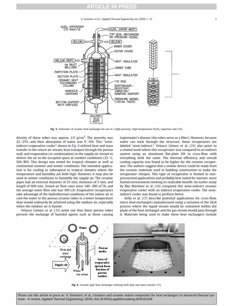
Fig. 3. Schematic of ceramic heat exchanger for use in a high-pressure, high-temperature H2SO4 vaporizer unit [14].
A. Sommers et al. / Applied Thermal Engineering xxx (2010) 1e15 5
ARTICLE IN PRESS
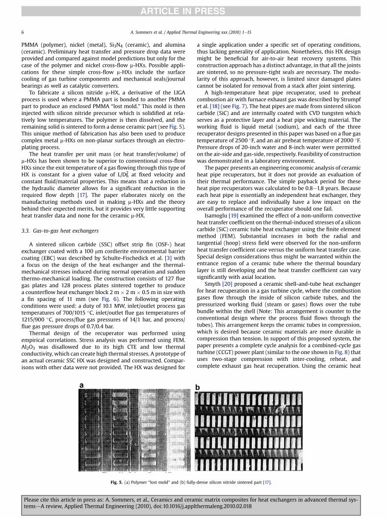
density of these tubes was approx. 2.5 g/cm3. The porosity was22e25%, and their absorption of water was 9e10%. This “semi-indirect evaporative cooler” shown in Fig. 4 utilized heat and masstransfer in the return air stream, heat transport through the porouswall, and evaporation (or condensation) in the supply air stream todeliver the air to the occupied space at comfort conditions (22 �C,50% RH). This design was tested for tropical climates as well ascontinental summer and winter conditions. The intended applica-tion is for cooling in subtropical to tropical climates where thetemperature and humidity are both high. However, it may also beused in winter conditions to humidify the supply air. The ceramicpipes had an external diameter of 25 mm, thickness of 5 mm, andlength of 600 mm. Tested air flow rates were 140e380 m3/h, andthe average water flow rate was 100 L/h. Evaporative recuperatorstake advantage of the hydrothermal conditions of the indoor air tocool the water in the porous ceramic tubes to a lower temperaturethan would ordinarily be achieved using the outdoor air, especiallywhen the outdoor air is humid.
Velasco Gómez et al. [15] point out that these porous tubesprevent the exchange of harmful agents such as those causing
Fig. 4. Ceramic pipe heat exchanger utiliz
Please cite this article in press as: A. Sommers, et al., Ceramics and ceramtemsdA review, Applied Thermal Engineering (2010), doi:10.1016/j.applt
Legionnaire's disease (the tubes serve as a filter). However, becausewater can wick through the structure, these recuperators arelabeled ‘semi-indirect.” Velasco Gómez et al. [15] also point toa related work where this recuperator was compared to an indirectsystem using an aluminum flat-plate HX in cross-flow witheverything held the same. The thermal efficiency and overallcooling capacity was found to be higher for the ceramic recuper-ator. The authors suggest that a similar device could be made fromthe ceramic materials used in building construction to make therecuperator cheaper. This type of recuperator is limited to non-pressurized applications and probably best suited for warmer, morehumid environments limiting its realizable benefit. An earlier studyby Rey Martínez et al. [16] compared this semi-indirect ceramicevaporative cooler with an indirect evaporative cooler. The semi-indirect cooler was found to perform better.
Kelly et al. [17] describe potential applications for cross-flow,micro heat exchangers manufactured using a variation of the LIGAprocess where the liquid stream would be contained within theplane of the heat exchanger and the gas streamwould pass throughit. Materials being used to make these heat exchangers include
ing both heat and mass transfer [15].
ic matrix composites for heat exchangers in advanced thermal sys-hermaleng.2010.02.018
A. Sommers et al. / Applied Thermal Engineering xxx (2010) 1e156
ARTICLE IN PRESS
PMMA (polymer), nickel (metal), Si3N4 (ceramic), and alumina(ceramic). Preliminary heat transfer and pressure drop data wereprovided and compared against model predictions but only for thecase of the polymer and nickel cross-flow m-HXs. Possible appli-cations for these simple cross-flow m-HXs include the surfacecooling of gas turbine components and mechanical seals/journalbearings as well as catalytic converters.
To fabricate a silicon nitride m-HX, a derivative of the LIGAprocess is used where a PMMA part is bonded to another PMMApart to produce an enclosed PMMA “lost mold.” This mold is theninjected with silicon nitride precursor which is solidified at rela-tively low temperatures. The polymer is then dissolved, and theremaining solid is sintered to form a dense ceramic part (see Fig. 5).This unique method of fabrication has also been used to producecomplex metal m-HXs on non-planar surfaces through an electro-plating process.
The heat transfer per unit mass (or heat transfer/volume) ofm-HXs has been shown to be superior to conventional cross-flowHXs since the exit temperature of a gas flowing through this type ofHX is constant for a given value of L/Dh
2 at fixed velocity andconstant fluid/material properties. This means that a reduction inthe hydraulic diameter allows for a significant reduction in therequired flow depth [17]. The paper elaborates nicely on themanufacturing methods used in making m-HXs and the theorybehind their expected merits, but it provides very little supportingheat transfer data and none for the ceramic m-HX.
3.3. Gas-to-gas heat exchangers
A sintered silicon carbide (SSC) offset strip fin (OSF-) heatexchanger coated with a 100 mm cordierite environmental barriercoating (EBC) was described by Schulte-Fischedick et al. [3] witha focus on the design of the heat exchanger and the thermal-mechanical stresses induced during normal operation and suddenthermo-mechanical loading. The construction consists of 127 fluegas plates and 128 process plates sintered together to producea counterflow heat exchanger block 2 m � 2 m � 0.5 m in size witha fin spacing of 11 mm (see Fig. 6). The following operatingconditions were used: a duty of 10.1 MW, inlet/outlet process gastemperatures of 700/1015 �C, inlet/outlet flue gas temperatures of1215/900 �C, process/flue gas pressures of 14/1 bar, and process/flue gas pressure drops of 0.7/0.4 bar.
Thermal design of the recuperator was performed usingempirical correlations. Stress analysis was performed using FEM.Al2O3 was disallowed due to its high CTE and low thermalconductivity, which can create high thermal stresses. A prototype ofan actual ceramic SSC HX was designed and constructed. Compar-isons with other data were not provided. The HX was designed for
Fig. 5. (a) Polymer “lost mold” and (b) fully-
Please cite this article in press as: A. Sommers, et al., Ceramics and ceramtemsdA review, Applied Thermal Engineering (2010), doi:10.1016/j.appl
a single application under a specific set of operating conditions,thus lacking generality of application. Nonetheless, this HX designmight be beneficial for air-to-air heat recovery systems. Thisconstruction approach has a distinct advantage, in that all the jointsare sintered, so no pressure-tight seals are necessary. The modu-larity of this approach, however, is limited since damaged platescannot be isolated for removal from a stack after joint sintering.
A high-temperature heat pipe recuperator, used to preheatcombustion air with furnace exhaust gas was described by Strumpfet al. [18] (see Fig. 7). The heat pipes are made from sintered siliconcarbide (SiC) and are internally coated with CVD tungsten whichserves as a protective layer and a heat pipe wicking material. Theworking fluid is liquid metal (sodium), and each of the threerecuperator designs presented in this paper was based on a flue gastemperature of 2500 �F, and an air preheat temperature of 2000 �F.Pressure drops of 20-inch water and 8-inch water were permittedon the air-side and gas-side, respectively. Feasibility of constructionwas demonstrated in a laboratory environment.
The paper presents an engineering economic analysis of ceramicheat pipe recuperators, but it does not provide an evaluation oftheir thermal performance. The simple payback period for theseheat pipe recuperators was calculated to be 0.8e1.8 years. Becauseeach heat pipe is essentially an independent heat exchanger, theyare easy to replace and individually have a low impact on theoverall performance of the recuperator should one fail.
Isamoglu [19] examined the effect of a non-uniform convectiveheat transfer coefficient on the thermal-induced stresses of a siliconcarbide (SiC) ceramic tube heat exchanger using the finite elementmethod (FEM). Substantial increases in both the radial andtangential (hoop) stress field were observed for the non-uniformheat transfer coefficient case versus the uniform heat transfer case.Special design considerations thus might be warranted within theentrance region of a ceramic tube where the thermal boundarylayer is still developing and the heat transfer coefficient can varysignificantly with axial location.
Smyth [20] proposed a ceramic shell-and-tube heat exchangerfor heat recuperation in a gas turbine cycle, where the combustiongases flow through the inside of silicon carbide tubes, and thepressurized working fluid (steam or gases) flows over the tubebundle within the shell (Note: This arrangement is counter to theconventional design where the process fluid flows through thetubes). This arrangement keeps the ceramic tubes in compression,which is desired because ceramic materials are more durable incompression than tension. In support of this proposed system, thepaper presents a complete cycle analysis for a combined-cycle gasturbine (CCGT) power plant (similar to the one shown in Fig. 8) thatuses two-stage compression with inter-cooling, reheat, andcomplete exhaust gas heat recuperation. Using the ceramic heat
dense silicon nitride sintered part [17].
ic matrix composites for heat exchangers in advanced thermal sys-thermaleng.2010.02.018

Fig. 6. (a) Schematic of the heat exchanger body showing the flow directions and (b) a sintered SiC process gas plate [3].
A. Sommers et al. / Applied Thermal Engineering xxx (2010) 1e15 7
ARTICLE IN PRESS
exchanger in this system could raise the thermal efficiency ofa closed gas turbine power cycle to approximately 65% from 55% forconventional combined-cycle power plant. The cycle studied wasa 100 MW unit, with a turbine inlet temperature of 1260 �C. Thecompression ratio was 14:1 with an air mass flow rate of 150 kg/s.
Smyth [20] also discussed the problem areas associated withceramic heat exchanger construction. These problematic designareas include: stress prediction and control on structural compo-nents, especially joints, fouling and cleaning issues, repairabilitywith the capability to selectively replace parts, endurance tothermal cycling, and gas tight bonding of metalliceceramic inter-faces. The most novel idea, however, in this paper involves main-taining the ceramic components in compression (perhaps bya pressurized process fluid) since ceramic components have muchbetter strength in compression than ceramic components intension.
In gas turbine applications, ceramics also continue to playa significant role [21,22]. For example, Zhong and Brown [22] reporta new integrally-woven ceramic matrix composite (CMC) materialthat creates the possibility for multi-hole cooling of combustorliners as shown in Fig. 9. In the area of thermal barrier coatings(TBCs), Vaben et al. [23] report a new class of double-layer coatingsin which conventional yttria-stabilized zirconia (YSZ) is used as thebottom layer, and newmaterials such as pyrochlores or perovskitesare used for the topcoat layer. Besides higher temperature capa-bility, these coatings can be tailored to have sensorial properties forimproved temperature control and monitoring. A summarizingwork on the current state-of-the-art of ceramic thermal barriercoating research in Europe is Vaben et al. [24]. And in automotiveapplications, a new flame-sprayed zirconia-based coating
Fig. 7. Schematic of a ceramic h
Please cite this article in press as: A. Sommers, et al., Ceramics and ceramtemsdA review, Applied Thermal Engineering (2010), doi:10.1016/j.applt
developed by ZIRCOTEC has been reported to reduce heat transferin exhaust manifolds by up to 26.7%, which equates to a surfacetemperature reduction of 135 �C [25].
3.4. Heat sinks
Bower et al. [26] described six different SiC heat sinks,3.2 cm � 2.2 cm in platform area of varying thickness, channeldiameter, number of channel rows, and number of channels perrow (see Fig. 10). These heat sinks were fabricated by co-extrudingmultiple layers of SiC filaments filled with a water-soluble polymercore (later removed during thermal processing). Water was passedthrough these heat sinks at 500 mL/min, and the thermal perfor-mance was measured using type-K thermocouples and pressuretaps and compared to laminar flow theory.
The bulk thermal conductivity of SiC (in this study) was only15 W/m �C, but because the CTE closely matches silicon, SiC is anideal candidate for integration into microelectronic applications.Despite the low thermal conductivity value, these SiC heat sinksprovided a thermal performance similar to a copper baseline heatsink at the same flow rate. The thermal resistance and Nusseltnumber data (shown in Fig. 11) suggest that multiple-row SiC heatsinks perform better than single-row designs. However, Bower andco-workers [26] conjecture that an optimum number of rows exist.The authors also assert that air-cooled heat sinks are limited to100 W/cm2 heat rejection, but water-cooled, microchannel heatsinks can achieve up to 790 W/cm2. Friction factor data comparefavorably to the Shah and London correlation, and the Nusseltnumber data compare favorably to the solution by Hausen forthermally developing, hydrodynamically developed flow. These
eat pipe recuperator [18].
ic matrix composites for heat exchangers in advanced thermal sys-hermaleng.2010.02.018

Fig. 8. Combined cycle gas turbine power plant with a high temperature ceramic heatexchanger [3].
A. Sommers et al. / Applied Thermal Engineering xxx (2010) 1e158
ARTICLE IN PRESS
experiments were performed with great attention to detail.However, physical irregularities in the channels (size and shapedistribution) were observed due to the fabrication method.
The very high cost (up to $10,000/kg) of CeC compositescombined with their lengthy (up to 9 month) processing time hashindered their wide-spread commercialization as heat sinks.Kowbel et al. [27,28] developed low cost, high thermal conductivity2D CeC and 2-D C-SIC composites for Si-based and GaAs-basedelectronics. Both 2-D CeC and 2-D C-SIC greatly outperformedstate-of-the-art CueW, AIN and BeO heat spreaders (see Fig. 12).The relatively low through-thickness thermal conductivity of CeCand C-Sic composites does not negatively affect their thermalperformance up to 44W/cm2. Chips were attached to both CeC andCeSiC via epoxy bonds. Up to 500 thermal cycles were performedsatisfactorily. The price of CeC composites has greatly reduced toless than $100/lb. This allowed the fabrication of CeC and C-Sic heatspreaders at a cost comparable to CueW ($2/in2).
4. Manufacturing methods and limitations of ceramics andCMCs
When introducing ceramic and ceramic matrix compositematerials in heat exchangers either by replacing the materials ofexisting designs or by implementing new configurations, it isnecessary to consider special needs during manufacturing,handling, and operation processes. For example, the coefficient of
Fig. 9. Integrally-woven SiC/SiC ceramic matrix comp
Please cite this article in press as: A. Sommers, et al., Ceramics and ceramtemsdA review, Applied Thermal Engineering (2010), doi:10.1016/j.appl
thermal expansion varies widely depending on the type of mate-rials (see Fig. 13). When dissimilar materials are interfaced, differ-ential thermal expansion or contraction can have a pathologicalimpact on the long-term durability of the heat exchangers. In thissection, the essential aspects of implementing of ceramic materialsin heat exchangers are further examined.
Various manufacturing methods available for using ceramicmaterials to construct heat exchangers are reviewed. Detailedfabrication procedures include forming primary components fromraw materials, subsequent machining, joining, bonding, andassembling. While some of the techniques are currently being usedfor commercial products, further developments of manufacturingmethods are needed for a wider use of ceramic materials in heatexchangers in HVAC&R and recovered-energy applications. Webelieve that the benefits of ceramic heat exchangers could drive thedevelopment of novel manufacturing methods as well as theassessment of material compatibility and long-term durability.
The methods used for manufacturing ceramic heat exchangerscan be classified as either monolithic assembly or non-monolithicassembly, depending on whether the heat exchanger componentsare permanently joined or not. Ceramic materials can be furtherclassified depending on their composition and structure. Crystal-line ceramic materials, which are more commonly used in theconstruction of a heat exchanger, are not amenable to a great rangeof processing options. Typically, the ceramic is made into thedesired shape in one of two ways: (a) by reaction in situ, or (b) by“forming” the desired object using powders and then sintering it toform a solid body. Ceramic forming techniques include throwing,slip casting, tape casting, injection molding, dry pressing, andvarious hybrid approaches. Non-crystalline ceramics tend to beformed from melts. The glass is shaped by casting when fullymolten or by blowing when highly viscous. If heat-treatmentsresult in a partially crystalline structure, the resulting material istypically referred to as a glass-ceramic. In most cases, however, themethod of manufacture is fairly complex involving semi-discon-tinuous assembly and frequently, a large expenditure of time.However, new manufacturing methods are making these limita-tions less and less of a concern. In fact, in some cases, the method ofmanufacture may even become the selling point.
The choice of monolithic versus non-monolithic assemblyfrequently depends on the chosen configuration of the heatexchanger. In monolithic assembly, the individual heat exchangecomponents are bonded together using slip and then re-fired tocreate an integral piece. This type of assembly may or may notinclude the plenum and ductwork; nevertheless, if the core of theheat exchanger is produced in this manner, it is referred to as being
osite materials for gas turbine applications [22].
ic matrix composites for heat exchangers in advanced thermal sys-thermaleng.2010.02.018

Fig. 10. Photographs and schematic of representative SiC heat sink samples [26].
A. Sommers et al. / Applied Thermal Engineering xxx (2010) 1e15 9
ARTICLE IN PRESS
monolithic. This method of assembly is desirable for one majorreason. There are no internal joints and therefore no attendantproblems with sealing. The major drawback of this method is tiedup in the advantagedthe entire heat exchanger must be replacedafter failure. Individual parts and components cannot be swappedand exchanged. Also, the monolithic assembly method can causestress concentrations under extreme operating conditions that mayshorten the life of the heat exchanger resulting in more frequentservicing and/or replacement.
In non-monolithic assembly, the heat exchanger is constructedfrom individual components and therefore can be disassembledand repaired. This is its major advantage. Accompanying this choiceof assembly, however, is the need for mechanical joints andsealsdhistorically, a problem area for ceramics due to their brit-tleness and the difficulties of forming a resilient metal-ceramic orceramiceceramic joint. The joining of two dissimilar materialsposes a problem because stresses can arise at the interface due todifferences in the coefficient of thermal expansion (CTE) of the twomaterials. To prevent leakage through the seal, advanced surfacemachining techniques are often necessary. In order to work aroundthese difficulties, a compliant material is often used in ceram-iceceramic joints that allows for the release of these stresses whilestill providing good sealing. This material can be: (1) a cement, (2)a packing, or (3) a glass. Cements have the advantage of conformingto the surfaces being bonded; however, its strength must betailored in such a way that permits it to yield at lower stresses thanthe surrounding ceramic materials. Packing is more commonlyused because of its high fiber density which makes it a highly
Fig. 11. (a) The thermal resistance of water-cooled heat sinks is significantly lower that air-cobserved to increase as the number of rows increased [26].
Please cite this article in press as: A. Sommers, et al., Ceramics and ceramtemsdA review, Applied Thermal Engineering (2010), doi:10.1016/j.applt
compliant, amorphous sealing material. However, at very highoperating temperatures, this type of sealing becomes crystallineand loses some of its resilience. This type of seal is also not well-suited for high-pressure applications. The glass joint design similarto the cement joint design also requires a careful tailoring of thematerial properties. In particular, the viscosity must be tailoredto ensure that the glass does not flow out of the joint at hightemperature.
In one study, packingmaterial was used to provide a ceramic-to-metal seal in an application with a high-pressure differential(>10 bar). Siliconized silicon carbide (SieSiC) tubes were utilized,and the seal was shown to slip under very low axial forces andprevent the tubes from being put in tension. A floating head designtype was not considered since a complex pattern of compressionand tension was expected to occur in regions of temperaturediscontinuity [29].
Another novel bonding option is laser supported brazing whichcan be used to join ceramic materials with other ceramic materialsand even with metals. In Rohde et al. [30], Al2O3-ceramics werebrazed to steel using a CO2-laser and an active braze filler material.The microstructural characteristics of the interface were examinedas well as the mechanical strength of the brazed joint usingbending tests. The bending strength was found to vary between 40and 80 MPa. In Lippmann et al. [31], an innovative laser joiningprocess is described that permits tight binding between ceramicbodies of any shape (see Fig. 14). The method is based on a solderthat is specially made from Al2O3, Y2O3 and SiO2 and melted locallyby use of laser radiation. The soldering process can be carried out in
ooled sinks for modest flow rates, and (b) the Nusselt number based on base area was
ic matrix composites for heat exchangers in advanced thermal sys-hermaleng.2010.02.018

Fig. 12. Thermal Spreader Results [27,28].
Fig. 14. Laser bonded hollow SiC capsule showing the applicability of the laser inducedsoldering technique [31].
A. Sommers et al. / Applied Thermal Engineering xxx (2010) 1e1510
ARTICLE IN PRESS
the free atmosphere (i.e. no vacuum, no inert gas), and the surfacesdo not require preparing. The resulting joints are temperatureresistant at 1600 �C and above. The mechanical strength of thejoined material was also evaluated using a 4-point bending test,and the bonded specimens were found to have a strength of236 MPa in comparison to the reference specimens which hada strength of 341 MPa.
A few different monolithic manufacturing methods will now bediscussed in greater detail. Schmitt et al. [32] described theconstruction of a catalytic, ceramic micro-structured plate micro-reactor. The manufacturing process begins with the casting of theceramic “green” tape from a slip made from a particular form ofa-alumina. The raw a-alumina tape is then cut into sheets usinga laser, stacked into the desired arrangement, and laminated beforebeing sintered together. This porous ceramic structure is thenexternally and internally sealed, and finally the reaction chamber iscoated with catalyst. This process is illustrated below in Fig. 15. Theactual tape casting was performed using the so-called “doctor bladeprocess” illustrated in Fig. 16 where a casting substrate of poly-ethylene film is drawn at constant speed under a slip reservoir. Theslip is then formed using two doctor blades whose height isadjusted to provide a uniform film on the casting substrate. Tapethicknesses between 0.1 and 1.2 mmwere manufactured using thismethod. The connections to external equipment were accom-plished using perfluorinated rubber O-rings which can withstandtemperatures up to approx. 320 �C. This, of course, places a signif-icant limitation on the maximum operating temperature of theheat exchanger. Complete sealing of the internal porous partition
Fig. 13. The difference in linear thermal expansion between metals and ceramics canbe significant.
Please cite this article in press as: A. Sommers, et al., Ceramics and ceramtemsdA review, Applied Thermal Engineering (2010), doi:10.1016/j.appl
plates which separate the reaction and cooling chambers was alsodifficult to obtain. However, using chemical vapor deposition (CVD)reductions in permeability from 29,500 nano-Perm to 270 nano-Perm after 40 h of reaction time were achieved.
In a paper by Alm et al. [7], the thermal performance of analumina micro ceramic heat exchanger comprised of 26.25 mm �26.25 mm plates containing channels 250 mmwide and 500 mm talland 12.25 mm in length is described. The micro-components werefabricated using the rapid prototyping assembly approach shown inFig. 17. First, a polymer master model was made of the originalusing stereolithography, and then a silicon mold was made. Next,“green bodies” were produced from an alumina/binder (MR52)dispersion through a low-pressure, injection molding process.Finally, the green bodies undergo a debinding step at 500 �C anda sintering step at 1700 �C. The joining of ceramic components wasperformed two waysd(1) by the hot joining of green bodies fol-lowed by group debinding/sintering, or (2) by the joining of alreadysintered micro-components by glass solder. It was found that thehot joining of green bodies was less reproducible at higher pres-sures. Therefore, joining by glass solder was preferred but some-times resulted in partially blocked (or completely blocked) channelpassages. Other germane studies concerned with issues related tothe manufacture of ceramic materials for heat exchange applica-tions include Payne and Evans [33] and Meschke et al. [34].
5. Exploitation of the novel properties of ceramics andceramic matrix composites (CMCs)
The key features of ceramics and ceramic matrix composites(CMCs) were also investigated in this study to identify specific usesin heat exchangers. These efforts can be divided into three mainareas: (1) replacement of construction materials for existing geome-tries, (2) major configurational changes resulting from the adoption ofnew geometrical concepts, and (3) utilization of advanced fabri-cation technologies to maximize the benefit from new materials.The possibility of improving conventional heat exchangers throughceramic materials was primarily explored via the replacing of partsof heat exchangers (e.g. fins or tubes) with new parts with minorgeometrical modifications. Good performance evaluation criteriawere needed to facilitate an even-handed comparison between themost competitive conventional materials (copper, aluminum,stainless steel, etc.) and possible ceramic alternatives and to helpidentify suitable geometric ranges and operating conditions.Because the merits of materials may rely on multiple factors,
ic matrix composites for heat exchangers in advanced thermal sys-thermaleng.2010.02.018

Fig. 15. Manufacturing process for the construction of a ceramic plate heat exchanger from green tape [32].
A. Sommers et al. / Applied Thermal Engineering xxx (2010) 1e15 11
ARTICLE IN PRESS
including enhanced convective heat transfer, higher thermalconductivity, low flow friction and size reduction, suitablecomparison methods were divided into target applications differ-entiating the types of heat transfer systems and the fluids involved.
In order to find alternative materials for a part of a heatexchanger with a specific configuration, it is necessary to considerthe desirable characteristics of the candidate changes. For example,air-side fins for some compact heat exchangers may benefit morefrom high thermal conductivity than from high structural strength.On the other hand, structural strength may be more importantwhen considering a refrigerant tube. While some of these charac-teristics are directly linked to the figures of merit, other factors,especially those related to reliability or application compatibility,may not be easily converted to a single figure of merit. An appli-cable performance evaluation method, which combines thethermal-hydraulic performance and qualitative properties, wasdeveloped by employing a Pugh Matrix for each target application.
Based on the property features of ceramics, a few of the prom-ising ceramic materials (SiC and SiC/SiC composites) were selectedfor further evaluation as candidate materials. Table 5 gives thedefinitions of these rating grades for each criterion, and Table 6gives the rating grades for these candidate materials.
Fig. 16. The so-called doctor blade process for the production of green tape [32].
Please cite this article in press as: A. Sommers, et al., Ceramics and ceramtemsdA review, Applied Thermal Engineering (2010), doi:10.1016/j.applt
The shaping criterion denotes the current capability to machinecomplex geometries for each kind of material. It reflects the cost ofthe materials to be manufactured. The cost associated with fittingdifferent parts (i.e. joining or bonding) is not included because itdepends on the materials to be fitted. Therefore, to make theevaluation fairly straightforward, the “fitting evaluation” wasexcluded from the above ten performance criteria for each appli-cation. As a general guideline, polymers and discontinuouscomposites are easily shaped into complex geometries by themold-casting method. The machining cost of ceramic composites,however, is often higher than other materials due to their hardnessand the increased difficulty of manufacture.
Thematerial cost criterion denotes the cost of the material itself.It depends to large extent on the quality and method ofmanufacturing the material. Thus, copper and ceramic compositesare always in the highest range of the material cost in present,while aluminum (and most polymers) are in the cheapest range.The thermal conductivities and densities of these materials wereretrieved from property databases. The temperature limits of thesematerials can usually be ranked in the following ascendingorderdpolymers, metals, ceramics, ceramic matrix composites(CMCs), and carbon materials. The material strength criteriondenotes the mechanical properties of these materials. It isa complex issue, and many factors are involved.
The criterion of compatibility with working fluids was separatedinto three categories: with halocarbon and ammonia refrigerants,with LiBreH2O and ammoniaewater systems, and with highlycorrosive fluids. It will be more convenient to evaluate differentapplications. This criterion includes resistance to chemical attackand permeability of the materials. Fouling resistance is anothercriterion which will influence the performance of heat exchangersover time. Usually, ceramics and polymers possess the highestfouling resistance. After carefully assigning rating grades for eachmaterial and each criteria, a few heat transfer applications whereceramic materials could be (or, currently are) competitive weresuggested. These target applications are discussed in the nextsection in more detail.
6. Possible target applications of ceramics and CMCs
Using these criteria, five different heat exchanger applicationswere identified where the replacement of construction materialswith ceramic could be advantageous over other materials.
ic matrix composites for heat exchangers in advanced thermal sys-hermaleng.2010.02.018

Fig. 17. Rapid prototyping process for the manufacture of ceramic heat exchangers [7].
A. Sommers et al. / Applied Thermal Engineering xxx (2010) 1e1512
ARTICLE IN PRESS
6.1. Evaporators in evaporative cooling systems for air-conditioning
In direct evaporative cooling systems, the cooling water iscooled as it flows through the tubes of the evaporator. An air flow isforced across the outside of the evaporators with a series nozzlesspraying water directly over the tubes. Water lost through evapo-ration is replaced by make-up water. Such evaporators have somefeatures of both air-cooled and water-cooled condensers. But theyare very sensitive to fouling, because impurities remain behindwhen the water is evaporated.
In these applications, tube and fin-and-tube heat exchangers arecommonly used. However, the structural strength of the tubes, finsand headers in this kind of evaporator is much less important thanin other systems because the pressure inside the tubes is usually nomore than one atmosphere higher than the ambient air pressure.Thus, these systems could benefit from ceramic tubes. In thesesystems, compatibility with coolant is less important because theoutside wet surface of the tubes exposed to the air is prone to becorroded. Compatibility with halocarbon/NH3 and LiBreH2O isirrelevant in this application.
6.2. Recuperators and generators in LiBr/H2O absorption chillers forair-conditioning
Absorption chillers using the LiBreH2O mixture have manyadvantages, including quiet, reliable operation, reasonable effi-ciency, and the possibility of cooling through the recovery of co-generated heat. Thus, LiBr/H2O absorption chillers are widely usedwhere electricity is expensive but inexpensive heat is available.Large-capacity direct-fired and waste-heat driven cooling systems
Table 5Definitions of rating grades for properties of the candidate materials.
Criteria 1 2
Shaping (Machining) Very difficult DifficultMaterial cost Very high HighThermal conductivity (W/mK) 0.1e0 10e100Temperature limit (�C) <300 300e500Material strength Very low LowCompatibility with 3 fluids Very poor PoorFouling resistance Very poor PoorMaterial density (g/cm3) >8 5e8
Please cite this article in press as: A. Sommers, et al., Ceramics and ceramtemsdA review, Applied Thermal Engineering (2010), doi:10.1016/j.appl
have been studied and commercialized, but it is difficult to extendtheir use to small capacity air-conditioning systems. One obstacle toawider application of gas-fired absorption chillers is their high firstcost, which can exceed twice that of an electric unit on a per-tonbasis. Absorption machines consist mainly of heat exchangers, sotheir price is dominated by the heat exchanger cost. Therefore, thecost criterion is very important in this application. Usuallyabsorption machines work with shell-and-tube heat exchangers,which are more expensive at small scales, as compared to fin-and-tube designs. The structural strength of parting sheets and headersis less important than halocarbon/NH3 systems because they onlyneed to endure the vacuum pressure which is less than oneatmosphere. The structure strength of fins is unimportant, sincethere is usually no fin or few fins in these recuporators. Compati-bility with LiBr/H2O is very important for the parting sheets, finsand headers in this application.
Another major obstacle to greater application of LiBr/H2Oabsorption chillers is the corrosive nature of LiBr/H2O tomostmetalmaterials. The performance of LiBr/H2O absorption chillers can beimproved by using plate or plate-fin type recuperators in thesolution cycle. The heat exchanger fluids are both LiBr/H2O solu-tions. Thus, the recuperator may benefit from ceramic materials.The steam generating plate or plate-fin type generators may alsobenefit from ceramic materials for this same reason. In this device,the heat exchanger fluids are LiBr/H2O solution on one side andsteam on other side. In both cases, the main parts considered forreplacement are parting sheets, fins and headers.
Limited information is available describing the operation ofabsorption chillers with non-metallic and compact heat exchangers[35e38]. Flamensbeck et al. [35] designed, built, and tested
3 4 5
Moderate Easy Very easyModerate Low Very low100e250 250e400 >400500e1000 1000e1650 >1650Moderate High Very highModerate Good ExcellentModerate Good Excellent3e4 1e2 <1
ic matrix composites for heat exchangers in advanced thermal sys-thermaleng.2010.02.018

Table 6Rating grades for properties of ceramics versus conventional materials.
Criterion Metal Metal Metal Ceramic CMC
Copper Aluminum Stainlesssteel
SiC SiC/SiC
Shaping (Machining) 5 5 5 2 2Material cost 2 4 3 4 3Thermal conductivity 4 3 2 3 4Temperature limit 3 3 3 4 4Material strength 5 5 5 2 3Compatibility with halocarbon 5 5 5 5 5Compatibility with LiBreH2O 3 3 3 5 5Compatibility with corrosive
fluids2 2 4 5 5
Fouling resistance 3 3 3 5 5Material density (i.e. weight) 1 4 1 3 3
A. Sommers et al. / Applied Thermal Engineering xxx (2010) 1e15 13
ARTICLE IN PRESS
a double-effect absorption heat pump with a heating capacity ofabout 45 kW. The generator was a direct-fired pool boiling appa-ratus. All other components were plate heat exchangers. Theabsorbent was a mixture of 50% NaOH and 50% KOH. All heatexchangers except the direct-fired generator were plate heatexchangers and were constructed of stainless steel. In order tominimize corrosion, the generator was made of nickel. To overcomean unacceptably high-pressure drop, which would cause a loss intemperature lift when plate heat exchangers are used as theabsorber and evaporator, flash evaporation and adiabatic sprayabsorption were adopted, i.e. performing both absorption andevaporation adiabatically.
6.3. Primary heat exchangers in gas-fired furnaces for space heating
Tube or tube-fin type heat exchangers are targeted in thisapplication. The heat exchanger fluids are exhaust gas and water.The main parts considered for replacement are tubes, fins andheaders.
The conductivity is less important, because the temperaturedifference between exhaust gas and coolant is usually very large;often there is no fin or few fins on the gas-side. The exhaust gastemperature is usually higher than 500 �C. Thus, the temperaturelimits of the heat exchanger materials are very important in thisapplication. The compatibility with the coolant also becomes veryimportant since the parts of heat exchangers are exposed toa (potentially) corrosive gas in a high temperature environment.
6.4. High temperature recuperators and chemical digesters
Ponyavin et al. [39,40] performed a numerical analysis usingFLUENT of the thermal performance of a compact ceramic heatexchanger which will be used as a chemical decomposer for the
Fig. 18. Experimental Sherwood number data as a function of the R
Please cite this article in press as: A. Sommers, et al., Ceramics and ceramtemsdA review, Applied Thermal Engineering (2010), doi:10.1016/j.applt
production of hydrogen via the sulfuric acid decomposition reac-tion (T > 850 �C). The heat exchanger being modeled was manu-factured using fused ceramic layers and possessed channels lessthan 1 mm in size. In a related work, two fuel reformingmicrochambers (12 mm � 12 mm � 1 mm) were packed witha commercially available ceramic catalyst (i.e. CuO/ZnO/Al2O3) toaid in the production of hydrogen gas [41]. A compact ceramic heatexchange reformerwas also suggested by Zhang et al. [42] for use ina high temperature solid oxide fuel cell/gas turbine (SOFC/GT)system. In these systems, thewaste heat from the high temperaturefuel cell is used in the steam reforming reaction (I), water gas shiftreaction (II), and CO2 direct reforming reactions of methane (III) forthe production of hydrogen and other hydrocarbon fuels. Thepassage walls of the recuperator are coated with nickel whichserves as the catalyst in these reactions. In this study, a dynamicsimulation of a counterflow compact heat exchange reformer isperformed to study how various parameters such as the steam-to-carbon ratio, passage operating pressure, and hot gas inlettemperature affect the mole fractions of methane, hydrogen, andwater in the product stream. A modular-based, volume-resistancemodeling technique and lumped-distributed parameter method,however, was used so only general characterization and optimiza-tion guidelines could be performed. Due to the higher gastemperatures (often reaching 1200 K) and the corrosive nature ofsome of the produced gases, however, ceramic materials are (andwill likely remain) an attractive option for heat exchangerconstruction in these applications.
Other relevant studies of high temperature ceramic recuper-ators include Yang et al. [43], McDonald [44], McDonald [45], andOmatete et al. [46]. McDonald [44] argues that technology mayadvance to a stage where 40% efficiency may be attained by gasturbine engines using high-temperature metallic recuperators;however, in the long term, McDonald believes that the full perfor-mance potential of microturbines can be achieved only withceramic recuperators. Recently, McDonald and Rodgers [47]launched a three-year research and development effort aimed atdesigning, fabricating and testing a 7.5 kW ceramic microturbinedemonstrator, which for the first time would involve the couplingof a ceramic radial flow turbine, a ceramic combustor, anda compact ceramic high effectiveness recuperator. Utriainen andSundén [48] also advocates for new materials and new heattransfer surface designs for microturbine recuperators.
6.5. Open-cell foams for reactive heat exchange processes andfiltration
For filtration and catalytic heat exchange, high temperaturelimits and good fouling resistance are important since the pressuredrop can be significant in these applications. Some work hasalready been performed in this area. Lévêque et al. [49] examined
eynolds number for nine different alumina foam samples [57].
ic matrix composites for heat exchangers in advanced thermal sys-hermaleng.2010.02.018

Fig. 19. Heat transfer comparison between equivalent 30-PPI a-Al2O3 foam andparticle beds [54].
A. Sommers et al. / Applied Thermal Engineering xxx (2010) 1e1514
ARTICLE IN PRESS
the hydraulic performance of a silicon carbide (b-SiC) foam forpossible use in a distillation column. The tested foam had a volumevoid fraction of 92%, and a specific area of 640 m2/m3. The pressuredrop for the foamwas found to be slightly higher but comparable toother common packing materials such as M250Y, CY, and Pall rings.Good mass transfer performance was observed, and Lévêque et al.[49] suggest that the foam might be best used in reactive distilla-tion applications due to its unique structural and mechanicalproperties and its ability to be coated with catalyst. Coquard et al.[50] developed a FEM model for estimating the effective thermalconductivity of ceramic and metallic open-cell foams. The authorsalso noted that the concentration of the solid phase at the end ofadjoining struts slow down heat conduction in the cellular matrix.Thus, the repartition of the solid phase along the length of thestruts was identified as a key parameter affecting the conduction ofheat in these materials.
In another paper, Kim [51] used the porous ceramic material(ISOLITE�) as a catalyst support in a micro methanol reformer forportable fuel cell applications due to its large surface area andthermal stability. The catalyst support was composed of 40% Al2O3and 55% SiO2 with trace amounts of other metal oxides, and theporosity was approximately 71%. The average bulk pore size wasbetween 100 and 300 mm, while smaller scale pores were a fewmicrons. Other excellent studies concerned with ceramic catalyticfoams formicro-reaction and/ormicro-separation include Zampieriet al. [52], Peng and Richardson [53], Twigg and Richardson [54],and Tsinoglou et al. [55].
Albanakis et al. [56] evaluated the thermal-hydraulic behavior ofseveral porous materials when treated as volumetric receiversunder concentrated solar radiation. Various foam materialsincluding Ni and Ni alloy, inconel, copper, aluminum and SiC werestudied; however, only a detailed comparison between the Ni andinconel foams was provided. The pore size for the inconel andnickel foams was found to be 0.58e0.6 mm using X-ray micro-tomographs, and the porosities were 93% and 92% for the inconeland the Ni foams, respectively. In another study by Incera Garridoet al. [57], the mass transfer and pressure drop properties ofalumina (Al2O3) foams with pore densities between 10 and 45 PPIand porosities between 75% and 85% were evaluated. Correlationswere developed for the Sherwood number (dimensionless masstransfer coefficient) of the foams which was found to increase withdecreasing pore count at constant hydrodynamic conditions (seeFig. 18).
Thermal-hydraulic correlations can also be found in Peng andRichardson [53], Twigg and Richardson [54], Giani et al. [58], andGroppi et al. [59]. In Peng and Richardson [53], axial and radial
Please cite this article in press as: A. Sommers, et al., Ceramics and ceramtemsdA review, Applied Thermal Engineering (2010), doi:10.1016/j.appl
temperature profiles in 30 PPI a-Al2O3 foam cylinders are reportedfrom which radial heat transfer correlations were derived for one-and two-dimensional reactor models. The 1-D correlation devel-oped for the temperature range 100e400 �C agreed within 10%with that previously reported for 700e900 �C and gave an overallheat transfer coefficient that was about a factor of four higher thansmooth glass spheres (see Fig. 19).
7. Conclusions and recommendations
An extensive literature review and critical evaluation of thepotential benefits of ceramic and ceramic composite materials hasbeen conducted and has produced a thorough compilation ofperformance data, physical/chemical properties, and other char-acteristics. Key features of a few of the most promising ceramicmaterials have been investigated to identify specific usages in heatexchangers based on a rating system comprised of ten performanceevaluation criteria. The thermal and mechanical properties ofindividual ceramic materials were collected in tabular form;however, thermal-hydraulic performance data are found to belimited. Heat exchanger designs are explored including thereplacement of materials in existing designs and the use of thesenew materials with changes in heat exchanger configuration.
Possible uses for ceramic materials in heat exchangers that holdsubstantial relevance and potential merit are discussed; however,many of these proposed applications have not been sufficientlystudied to allow for a complete assessment of cost and benefit. Prac-tical issues related to implementing the designs, including thermalperformance, thermal/mechanical/environmental constraints, andmanufacturing and installation issues, were also considered.
References
[1] Z. Gurdal, R.T. Haftka, P. Hajela, Design and Optimization of LaminatedComposite Materials. John Wiley & Sons, New York, 1999.
[2] S. Richlen. A survey of ceramic heat exchanger opportunities. In: B.D. Foster, J.B. Patton (Eds.), Advances in Ceramics: Ceramics in Heat Exchangers, vol. 14,1985, pp. 3e14.
[3] J. Schulte-Fischedick, V. Dreißigacker, R. Tamme, An innovative ceramic hightemperature plate-fin heat exchanger for EFCC processes. Applied ThermalEngineering 27 (2007) 1285e1294.
[4] M. Steen, L. Ranzani, Potential of SiC as a heat exchanger material ina combined cycle plant. Ceramics International 26 (2000) 849e854.
[5] R. Smyth, The use of high temperature heat exchangers to increase powerplant thermal efficiency Article No. 97089. Energy Conversion EngineeringConference (1997) 1690e1695.
[6] H.-C. Liu, H. Tsuru, A.G. Cooper, F.B. Prinz, Rapid prototyping methods ofsilicon carbide micro heat exchangers. Proc. IMechE Part B: Journal of Engi-neering Manufacture 219 (2005) 525e538.
[7] B. Alm, R. Knitter, J. Haußelt, Development of a ceramic micro heat exchangerdesign, construction, and testing. Chemical Engineering&Technology 28 (2005)1554e1560.
[8] W. Krenkel, F. Berndt, C/CeSiC composites for space applications andadvanced friction systems. Materials Science and Engineering A 412 (2005)177e181.
[9] C. Luzzatto, A. Morgana, S. Chaudourne, T. O'Doherty, G. Sorbie, A new conceptcomposite heat exchanger to be applied in high-temperature industrialprocesses. Applied Thermal Engineering 17 (1997) 789e797.
[10] D.D.L. Chung, Materials for thermal conduction. Applied Thermal Engineering21 (16) (2001) 1593e1605.
[11] C. Zweben, Thermal materials solve power electronics challenges. PowerElectronics Technology 32 (2) (2006) 40e47.
[12] C. Zweben. Emerging high-volume applications for advanced thermallyconductive materials, International SAMPE Symposium and Exhibition(Proceedings) 49, SAMPE 2004 Conference Proceedings e Materials and Pro-cessing Technology e 60 Years of SAMPE Progress, 2004. pp. 4046e4057.
[13] B. Alm, U. Imke, R. Knitter, U. Schygulla, S. Zimmermann, Testing and simu-lation of ceramic micro heat exchangers. Chemical Engineering Journal 135S(2008) S179eS184.
[14] S. Ishiyama, S. Maruyama. Compact heat exchanger made of ceramics havingcorrosion resistance at high temperature, U.S. Patent No. 7,168,481 B2, 2007.
[15] E. Velasco Gómez, F.J. Rey Martínez, F. Varela Diez, M.J. Molina Leyva,R. Herrero Martín, Description and experimental results of a semi-indirectceramic evaporative cooler. International Journal of Refrigeration 28 (2005)654e662.
ic matrix composites for heat exchangers in advanced thermal sys-thermaleng.2010.02.018

A. Sommers et al. / Applied Thermal Engineering xxx (2010) 1e15 15
ARTICLE IN PRESS
[16] F.J. Rey Martínez, E. Velasco Gómez, R. Herrero Martín, J. Martínez Gutiérrez,F. Varela Diez, Comparative study of two different evaporative systems: anindirect evaporative cooler and a semi-indirect ceramic evaporative cooler.Energy and Buildings 36 (2004) 696e708.
[17] K.W. Kelly, C. Harris, L.S. Stephens, C. Marques, D. Foley, Industrial applicationsfor LIGA-fabricated micro heat exchangers. in: H. Helvajian, S.W. Janson,F. Lärmer (Eds.),MEMSComponents andApplications for Industry, Automobiles,Aerospace, and Communication, vol. 4559. Proceedings of SPIE, 2001, pp. 73e84.
[18] H.J. Strumpf, T.L. Stillwagon, D.M. Kotchick, M.G. Coombs, Advanced industrialceramic heat pipe recuperators. Heat Recovery Systems & CHP 8 (1988)235e246.
[19] Y. Islamoglu, Finite element model for thermal analysis of ceramic heatexchanger tube under axial non-uniform convective heat transfer coefficient.Materials and Design 25 (2004) 479e482.
[20] R. Smyth, A proposal for the use of a very high temperature ceramic heatexchanger in gas turbine power production Article No. 97088. EnergyConversion Engineering Conference (1997) 1696e1701.
[21] Development of ceramic heat exchanger for 300 kW-class gas turbine. Journalof the Gas Turbine Society of Japan 23 (90) (1999) 55e60.
[22] F. Zhong, G.L. Brown, Experimental study of multi-hole cooling for integrally-woven, ceramic matrix composite walls for gas turbine applications. Inter-national Journal of Heat and Mass Transfer 52 (2009) 971e985.
[23] R. Vaßen, A. Stuke, D. Stöver, Recent developments in the field of thermalbarrier coatings. Journal of Thermal Spray Technology 18 (2) (2009) 181e186.
[24] R. Vaßen, F. Cernuschi, G. Rizzi, A. Scrivani, N. Markocsan, L. Östergren,A. Kloosterman, R. Mevrel, J. Feist, J. Nicholls, Recent activities in the field ofthermal barrier coatings including burner rig testing in the European Union.Advanced Engineering Materials 10 (10) (2008) 907e921.
[25] Ceramic coating slashes heat transfer from exhaust manifolds. ProfessionalEngineering 21 (2) (2008) 49e49. Academic Search Complete, EBSCO host(accessed 28.08.09).
[26] C. Bower, A. Ortega, P. Skandakumaran, R. Vaidyanathan, T. Phillips, Heattransfer in water-cooled silicon carbide milli-channel heat sinks for highpower electronic applications. Journal of Heat Transfer 127 (2005) 59e65.
[27] W. Kowbel, J. Webb, J.C. Withers, Low-cost pitch and phenolic-based CeCcomposites for passive thermal managemen. International SAMPE Symposiumand Exhibition (Proceedings) vol. 44 (1999) 1878e1887.
[28] W. Kowbel, W. Champion, J.C. Withers, W. Shih, Low cost, high thermalconductivity composite heat spreaders for power electronics. SixteenthAnnual IEEE Semiconductor Thermal Measurement and ManagementSymposium (Cat. No.00CH37068) (2000) 195e200.
[29] S.B.M. Beck, P.R. Langston, B.C.R. Ewan, P.E. Messer, R. Smyth, J. Swithenbank,D.A.W. Taylor, Development of a high-temperature ceramic to metal seal.Proceedings of the Institution of Mechanical Engineers Part E e Journal ofProcess Mechanical Engineering 211 (2) (1997) 109e114.
[30] M. Rohde, I. Südmeyer, A. Urbanek, M. Torge, Joining of alumina and steel bya laser supported brazing process. Ceramics International 35 (2009) 333e337.
[31] W. Lippmann, J. Knorr, R. Wolf, R. Rasper, H. Exner, A.-M. Reinecke, M. Nieher,R. Schreiber, Laser joining of silicon carbideda new technology for ultra-hightemperature resistant joints.Nuclear EngineeringandDesign231 (2004) 151e161.
[32] C. Schmitt, D.W. Agar, F. Platte, S. Buijssen, B. Pawlowski, M. Duisberg, Ceramicplate heat exchanger for heterogeneous gas-phase reactions. Chemical Engi-neering & Technology 28 (2005) 337e343.
[33] C. Payne, J. Evans, Cross-flow ceramic structures produced by plastic pro-cessing. International Journal of Advanced Manufacturing Technology 14 (7)(1998) 508e513.
[34] F. Meschke, G. Riebler, V. Hessel, J. Schürer, T. Baier, Hermetic gas-tightceramic microreactors. Chemical Engineering and Technology 28 (4) (2005)465e473.
[35] M. Flamensbeck, F. Summerer, P. Riesch, F. Ziegler, G. Alefeld, A cost effectiveabsorption chiller with plate heat exchangers using water and hydroxides.Applied Thermal Engineering 18 (6) (1998) 413e425.
[36] A. Lowenstein, M. Sibilia, A Low-Cost Thin-Film Absorber/Evaporator for anAbsorption Chiller Final Report. AIL Research, Inc., Princeton, NJ, Apr 1993,Sponsor: Gas Research Inst., Chicago, IL, 44 pp..
[37] A.I. Lowenstein, M.J. Sibilia. Thin plastic-film heat exchanger for absorptionchillers, US Patent 718037, 1999.
Please cite this article in press as: A. Sommers, et al., Ceramics and ceramtemsdA review, Applied Thermal Engineering (2010), doi:10.1016/j.applt
[38] M. de Vega, J.A. Almendros-Ibañez, G. Ruiz, Performance of a LiBr-waterabsorption chiller operating with plate heat exchangers. Energy Conversionand Management 47 (18e19) (2006) 3393e3407.
[39] V. Ponyavin, Y. Chen, A.E. Hechanova, M. Wilson, Numerical modeling ofcompact high temperature heat exchanger and chemical decomposer forhydrogen production. Heat and Mass Transfer 44 (2008) 1379e1389.
[40] V. Ponyavin, Y. Chen, J. Cutts, M. Wilson, A.E. Hechanova, Calculation of fluidflow distribution inside a compact ceramic high temperature heat exchangerand chemical decomposer Article No. 061104. Journal of Fluids Engineering130 (2008) 1e8.
[41] K. Yoshida, S. Tanaka, H. Hiraki, M. Esashi, A micro fuel reformer integratedwith a combustor and a microchannel evaporator. Journal of Micromechanicsand Microengineering 16 (2006) S191eS197.
[42] H. Zhang, L. Wang, S. Weng, M. Su, Performance research on the compact heatexchange reformer used for high temperature fuel cell systems. Journal ofPower Sources 183 (2008) 282e294.
[43] C.-H. Yang, M. Yu, C.-H. Chen, C.-H. Chen, Performance simulation and thermalstress analysis of ceramic recuperators formed by SiC and MAS. NumericalHeat Transfer: Part A e Applications 53 (7) (2008) 709e725.
[44] C.F. McDonald, Emergence of Recuperated Gas Turbines for Power GenerationPaper No. 99-GT-67. ASME, Indianapolis, IN, 1999.
[45] C.F. McDonald, Low Cost Recuperator Concept for Microturbine ApplicationsPaper No. 2000-GT-0167. ASME, Munich, Germany, 2000.
[46] O.O. Omatete, P.J. Maziasz, B.A. Pint, D.P. Stinton, Assessment of recuperatormaterials for microturbines ORNL Report No. TM-2000/304. Metals andCeramics Division, Oak Ridge National Laboratory (December 2000).
[47] C.F. McDonald, C. Rodgers, Small recuperated ceramic microturbine demon-strator concept. Applied Thermal Engineering 28 (2008) 60e74.
[48] E. Utriainen, B. Sundén, Evaluation of the cross corrugated and some othercandidate heat transfer surface for microturbine recuperators. Journal ofEngineering for Gas Turbines and Power 124 (2002) 550e560.
[49] J. Lévêque, D. Rouzineau, M. Prévost, M. Meyer, Hydrodynamic and masstransfer efficiency of ceramic foam packing applied to distillation. ChemicalEngineering Science 64 (2009) 2607e2616.
[50] R. Coquard, M. Loretz, D. Baillis, Conductive heat transfer in metallic/ceramicopen-cell foams. Advanced Engineering Materials 10 (4) (2008) 323e337.
[51] T. Kim, Micro methanol reformer combined with a catalytic combustor fora PEM fuel cell. International Journal of Hydrogen Energy 34 (2009)6790e6798.
[52] A. Zampieri, P. Colombo, G.T.P. Mabande, T. Selvam, W. Schwieger,F. Scheffler, Zeolite coatings on microcellular ceramic foams: a novel routeto microreactor and microseparator devices. Advanced Materials 16 (9e10)(2004) 819e823.
[53] Y. Peng, J.T. Richardson, Properties of ceramic foam catalyst supports: one-dimensional and two-dimensional heat transfer correlations. Applied Catal-ysis A, General 266 (2) (2004) 235e244.
[54] M.V. Twigg, J.T. Richardson, Fundamentals and applications of structuredceramic foam catalysts. Industrial and Engineering Chemistry Research 46(2007) 4166e4177.
[55] D.N. Tsinoglou, P. Dimopoulos Eggenschwiler, T. Thurnheer, P. Hofer, Asimplified model for natural-gas vehicle catalysts with honeycomb and foamsubstrates. Proceedings of the Institution of Mechanical Engineers, Part D eJournal of Automobile Engineering 223 (6) (2009) 819e834.
[56] C. Albanakis, D. Missirlis, N. Michailidis, K. Yakinthos, A. Goulas, H. Omar,D. Tsipas, B. Granier, Experimental analysis of the pressure drop and heattransfer through metal foams used as volumetric receivers under concen-trated solar radiation. Experimental Thermal and Fluid Science 33 (2) (2009)246e252.
[57] G. Incera Garrido, F.C. Patcas, S. Lang, B. Kraushaar-Czarnetzki, Mass transferand pressure drop in ceramic foams: a description for different pore sizes andporosities. Chemical Engineering Science 63 (21) (2008) 5202e5217.
[58] L. Giani, G. Groppi, E. Tronconi, Mass-transfer characterization of metallicfoams as supports for structured catalysts. Industrial and EngineeringChemistry Research 44 (2005) 4993e5002.
[59] G. Groppi, L. Giani, E. Tronconi, Generalized correlation for gas/solid mass-transfer coefficients in metallic and ceramic foams. Industrial and EngineeringChemistry Research 46 (2007) 3955e3958.
ic matrix composites for heat exchangers in advanced thermal sys-hermaleng.2010.02.018


![Joining of SiC based ceramics and composites with Si-16Ti ...Joining of SiC based ceramics and composites with Si-16Ti and Si-18Cr 443 composites. The Si-Ti phase diagram [12] shows](https://static.fdocuments.net/doc/165x107/6130ec0a1ecc5158694467ee/joining-of-sic-based-ceramics-and-composites-with-si-16ti-joining-of-sic-based.jpg)