Cellular tubular structures from perforated metallic tape...
10
1053 Agronomy Research 14(S1), 1053–1062, 2016 Cellular tubular structures from perforated metallic tape and its application V. Mironovs 1 , I. Boiko 2,* , T. Koppel 3 and M. Lisicins 1 1 Riga Technical university, Faculty of Civil Engineering, Institute of Building Production, Azenes street 16/20–331, LV-1048 Riga, Latvia 2 Riga Technical University, Faculty of Mechanical Engineering, Transport and Aeronautics, Institute of Mechanical Engineering, Ezermalas street 6k, LV-1006 Riga, Latvia 3 Tallinn University of Technology, Department of Labor Environment and Safety, SOC351, Ehitajate tee 5, EE19086 Tallinn, Estonia * Correspondence: [email protected] Abstract. The objectives of performed research were the following: 1) check out the possibility of effective formation of the tubular and planar structures from the perforated steel tapes, which were obtained as a waste during stamping of fine-sized details, by cutting and bending; 2) testing of achieved tubular and annular structures for fixing up of the electrical cables and as electromagnetic shielding solutions; 3) analysis of achieved results and elaboration of the recommendations for using of lightweight tubular shields for the electrical cables. The actuality of research is connected with the re-using of metallic wastes and shielding solutions against electromagnetic fields. All objectives were reached successfully using bending for formation of the tubular structures. The bending strength of achieved structures and the shielding efficiency in a controlled environment was examined. The measurement results have shown that perforated steel will exhibit noticeable shielding properties against both the electric and magnetic field. Such results open up wide possible application of the planar and cellular tubular structures from perforated metallic tapes. Key words: perforated metallic waste, tubular structures, electromagnetic fields, shielding. INTRODUCTION During last years the perforated metallic materials (PMM) become more used in building industry and mechanical engineering. For example, such materials are widely used as spacers for wall and floor constructions, for containing walls or sandwich wall structures (Lisicins et al., 2015). Another popular application of PMM is using as reinforcement material in concrete works and brickworks (Kalva, 2011), as well as fixtures and connectors for nodes of wooden constructions (Ozola, 2011). The support structures consisting of an annular or tubular casing, which cavity is arranged with reinforcing member and filled with the infill material were proposed by Mironovs & Lisicins (2015). Due to light weight and decorative behaviour PMM also used for producing the elements of ventilation devices, filters, channels and heating systems. In such applications the tubular structures are usually used (Perforated metal, 2016). Also
-
Upload
trinhthien -
Category
Documents
-
view
224 -
download
3
Transcript of Cellular tubular structures from perforated metallic tape...
1053
Agronomy Research 14(S1), 1053–1062, 2016
Cellular tubular structures from perforated metallic tape and
its application
V. Mironovs1, I. Boiko2,*, T. Koppel3 and M. Lisicins1
1Riga Technical university, Faculty of Civil Engineering, Institute of Building
Production, Azenes street 16/20–331, LV-1048 Riga, Latvia 2Riga Technical University, Faculty of Mechanical Engineering, Transport and
Aeronautics, Institute of Mechanical Engineering, Ezermalas street 6k, LV-1006 Riga,
Latvia 3Tallinn University of Technology, Department of Labor Environment and Safety,
SOC351, Ehitajate tee 5, EE19086 Tallinn, Estonia *Correspondence: [email protected]
Abstract. The objectives of performed research were the following: 1) check out the possibility
of effective formation of the tubular and planar structures from the perforated steel tapes, which
were obtained as a waste during stamping of fine-sized details, by cutting and bending; 2) testing
of achieved tubular and annular structures for fixing up of the electrical cables and as
electromagnetic shielding solutions; 3) analysis of achieved results and elaboration of the
recommendations for using of lightweight tubular shields for the electrical cables. The actuality
of research is connected with the re-using of metallic wastes and shielding solutions against
electromagnetic fields. All objectives were reached successfully using bending for formation of
the tubular structures. The bending strength of achieved structures and the shielding efficiency in
a controlled environment was examined. The measurement results have shown that perforated
steel will exhibit noticeable shielding properties against both the electric and magnetic field. Such
results open up wide possible application of the planar and cellular tubular structures from
perforated metallic tapes.
Key words: perforated metallic waste, tubular structures, electromagnetic fields, shielding.
INTRODUCTION
During last years the perforated metallic materials (PMM) become more used in
building industry and mechanical engineering. For example, such materials are widely
used as spacers for wall and floor constructions, for containing walls or sandwich wall
structures (Lisicins et al., 2015). Another popular application of PMM is using as
reinforcement material in concrete works and brickworks (Kalva, 2011), as well as
fixtures and connectors for nodes of wooden constructions (Ozola, 2011). The support
structures consisting of an annular or tubular casing, which cavity is arranged with
reinforcing member and filled with the infill material were proposed by Mironovs &
Lisicins (2015). Due to light weight and decorative behaviour PMM also used for
producing the elements of ventilation devices, filters, channels and heating systems. In
such applications the tubular structures are usually used (Perforated metal, 2016). Also

1054
PMM have been actively used in the construction of cladding panels in residential
housing or as so called thermoprofiles (Garifullin et al., 2015).
Nowadays it is possible to produce the tubular structures from the PMM in wide
diapason of the diameters (from few mm to one and more meters) with length up to 10
meters and larger according to application (Wadley et al., 2003; Perforated metal, 2016).
The choice of manufacturing method for producing tubular structures from PMM is
based on the tube diameter and length, material thickness, mechanical properties of the
material etc. Mostly the welded tubular structures are used, which were produced from
the PMM tape by spiral twisting, winding, stretching and profiling (Wadley et al., 2003;
Wadley, 2006; Mironovs et al., 2013).
Mironovs et al. (2014) have shown the possibility of application of cellular
structures from perforated metallic tape for electromagnetic solutions, in particular
shields for electrical cables (Fig. 1). It should be mentioned, that it is necessary to
analyze the mechanical properties of PMM and achieved structures using appropriate
simulation and/or experimental evaluation methods (Ochsner et al., 2001; Vaz et al.,
2011; Bhavitha et al., 2015).
Figure 1. Application of cellular structures from MPP for placing of suspended cables in closed
construction (a) and open construction (b).
Mostly for manufacturing cellular structures the specially produced PMM are used.
More effective way is to use the perforated steel tapes, which are obtained as a waste
during stamping of fine-sized details, for example, elements of the leaf chain (Mironovs
et al., 2014). Since the base material usually is the structural steel with relative high
carbon content such metallic waste is characterized by high strength.
The main objective of performed research was the testing of tubular and annular
structures achieved by bending for fixing up of the electrical cables and as
electromagnetic shielding solutions. The actuality of research is connected with the re-
using of metallic wastes and shielding solutions against electromagnetic fields.
The necessity of shielding electromagnetic fields may be presented in many forms
(Borner et al., 2011; Koppel et al., 2013). In telecommunications shielding devices and
cables is aimed at preventing crosstalk and interference from a device to another. Such
interference or crosstalk may emanate from the cables that carry some sort of
communication signal. Even cables that just pass on a significant amount of the electrical
current may affect sensitive nearby electronic devices. In such case a shielding of the
cables is sought for.
1055
In this paper electromagnetic field measurements were conducted to determine the
shielding effectiveness of perforated steel elements placed around or next to the power
cables that irradiate extremely low frequency (power frequency 50 Hz) magnetic and
electric fields.
MATERIALS AND METHODS
Usually, the cable packages at a great length have a significant weight. Therefore
in case of placing those into suspended perforated metallic constructions under ceilings
the mechanical properties (especially bending strength) of perforated tubes are of great
importance. Mechanical and geometrical parameters of PST-2 type perforated steel tape
(trade mark of JSC ’DITTON Driving Chain Factory’, Latvia), which was used for
producing of perforated steel tubes for supporting and shielding of the cable packages
are shown in Table 1. This tape is achieved as a technological waste during stamping of
the elements of driving chains which are used in motor industry.
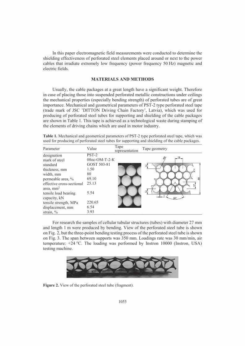
Table 1. Mechanical and geometrical parameters of PST-2 type perforated steel tape, which was
used for producing of perforated steel tubes for supporting and shielding of the cable packages.
Parameter Value Taperepresentation
Tape geometry
designation PST-2
mark of steel 08��-��-�-2-�
standard GOST 503-81
thickness, mm 1.50
width, mm 80
permeable area, % 69.10
effective cross-sectional
area, mm2
25.13
tensile load bearing
capacity, kN
5.54
tensile strength, MPa 220.65
displacement, mm 6.54
strain, % 3.93
For research the samples of cellular tubular structures (tubes) with diameter 27 mm
and length 1 m were produced by bending. View of the perforated steel tube is shown
on Fig. 2, but the three-point bending testing process of the perforated steel tube is shown
on Fig. 3. The span between supports was 350 mm. Loadings rate was 30 mm/min, air
temperature: +24 °C. The loading was performed by Instron 10000 (Instron, USA)
testing machine.
Figure 2. View of the perforated steel tube (fragment).
1056
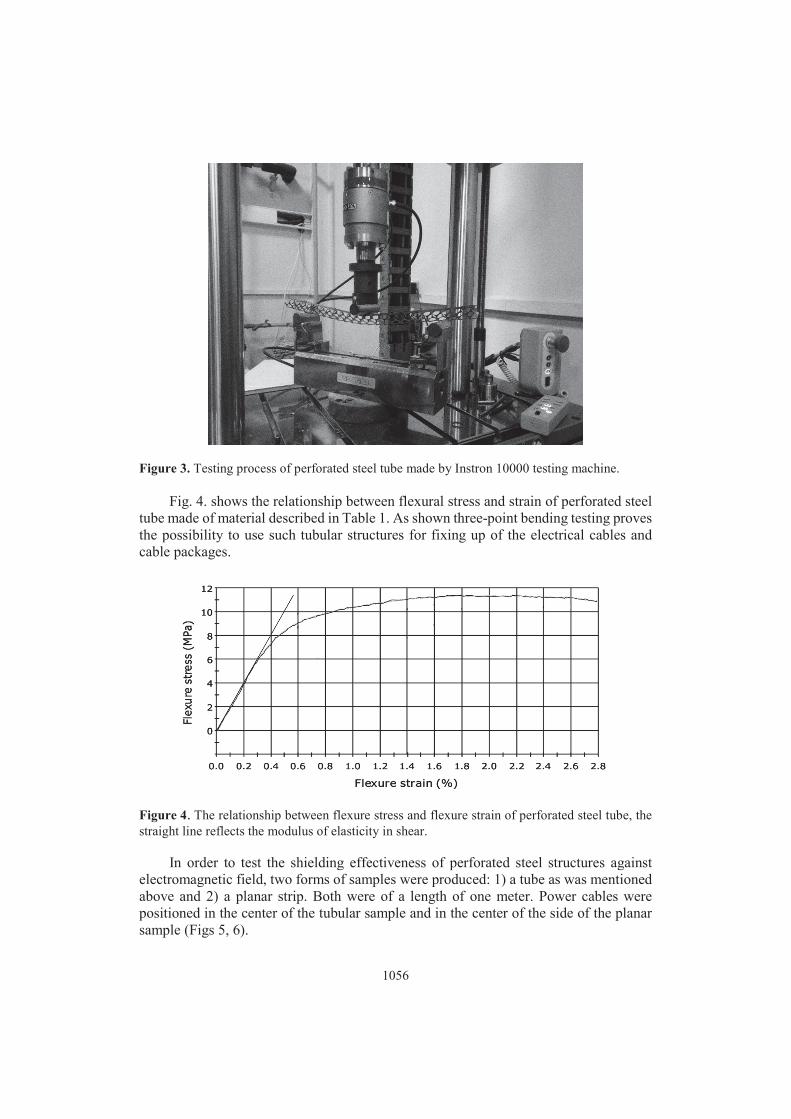
Figure 3. Testing process of perforated steel tube made by Instron 10000 testing machine.
Fig. 4. shows the relationship between flexural stress and strain of perforated steel
tube made of material described in Table 1. As shown three-point bending testing proves
the possibility to use such tubular structures for fixing up of the electrical cables and
cable packages.
Figure 4. The relationship between flexure stress and flexure strain of perforated steel tube, the
straight line reflects the modulus of elasticity in shear.
In order to test the shielding effectiveness of perforated steel structures against
electromagnetic field, two forms of samples were produced: 1) a tube as was mentioned
above and 2) a planar strip. Both were of a length of one meter. Power cables were
positioned in the center of the tubular sample and in the center of the side of the planar
sample (Figs 5, 6).
1057
A high current was run through 14 isolated copper cables (1.5 mm²). When an
electromagnetic field hits another material than the one it travels within, some of the
energy may be reflected and the rest transmitted through. In this study the effectiveness
of the shielding intervention is determined by measuring the electromagnetic field before
and after the intervention. The shielding articles are meant for power cables meaning the
frequency of 50 Hz.
The measurement device used was Gigahertz Solutions NFA400 (Langenzenn,
Germany). In order to guarantee the reliability of the measurement results the area was
constantly monitored for background electromagnetic fields, which topped at 9 nT
(nanoTeslas) for magnetic field and 5 V m-1 (Volts per meter) for electric field. It was
also controlled that no other electromagnetic field sources were nearby that would affect
the reading.
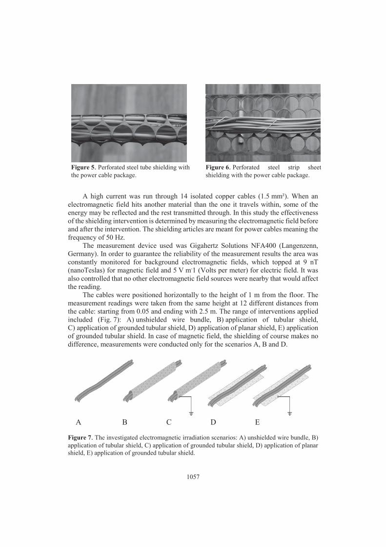
The cables were positioned horizontally to the height of 1 m from the floor. The
measurement readings were taken from the same height at 12 different distances from
the cable: starting from 0.05 and ending with 2.5 m. The range of interventions applied
included (Fig. 7): A) unshielded wire bundle, B) application of tubular shield,
C) application of grounded tubular shield, D) application of planar shield, E) application
of grounded tubular shield. In case of magnetic field, the shielding of course makes no
difference, measurements were conducted only for the scenarios A, B and D.
A B C D E
Figure 7. The investigated electromagnetic irradiation scenarios: A) unshielded wire bundle, B)
application of tubular shield, C) application of grounded tubular shield, D) application of planar
shield, E) application of grounded tubular shield.
Figure 5. Perforated steel tube shielding with
the power cable package.
Figure 6. Perforated steel strip sheet
shielding with the power cable package.

1058
In order to conduct measurements one must note the different field propagation
principles of electric and magnetic fields. In Fig. 8 the propagation path is pictured by
arrows. Whereas electric shielding is easier to achieve due to straightforward path of the
electric field lines. The magnetic field lines always need to finish the loop, making
encapsulating this more complex task.
Figure 8. A principal field propagation of magnetic (a) and electric (b) field in respect to the
planar and tubular shielding measures.
RESULTS AND DISCUSSION
For the electric field, the measurements clearly indicate the importance of
grounding the shield. Without the grounding, at 0.5 m the 100% of the planar shield and
78% of the tubular shield electric field passed through. While grounding the shield, at
0.5 m the transmission of the electric field was retained at 28% for the planar shield and
30% for the tubular shield (Fig. 9 and Table 2).

1059
Figure 9. Electric field strength for a wire bundle with (w.) and without (wo.) a perforated steel
cover.
Table 2. Electric field strength (V/m) for a wire bundle with and without a perforated steel cover:
A) unshielded wire bundle, B) application of tubular shield, C) application of grounded tubular
shield, D) application of planar shield (see Fig. 7)
Distance from
the wires, m A B C D E
0.05 1,016 906 120 821 230
0.1 628 614 99 536 175
0.25 354 326 73 231 101
0.5 185 187 52 145 56
0.75 100 105 34 81 38
1 61 62 22 55 24
1.25 38 37 15 35 16
1.5 22 23 9.3 24 11
1.75 14 15 5.9 13 6.1
2 10 11 5 8.5 5
2.25 5 6 5 6 5
2.5 5 5 5 5 5
In case of magnetic field the shielding effectiveness was less than compared to the
electric field attenuation. At 0.5 m distance 74% of the magnetic field passed through
the planar shield and 78% from the tubular shield (Fig. 10 and Table 3). In average the
transmission across all measurement distances was 77% for the planar shield and 67%
for the tubular shield.

1060
Figure 10. Magnetic field flux density for a wire bundle with (w.) and without (wo.) a perforated
steel cover.
Table 3. Magnetic field flux density for a wire bundle with and without a perforated steel cover:
A) unshielded wire bundle, B) application of tubular shield, D) application of planar shield
(see Fig. 7)
Distance from
the wires, m A D B
0.05 21,300 14,290 7,346
0.1 6,857 6,050 4,194
0.25 1,540 1,021 892
0.5 332 245 260
0.75 130 98 100
1 61 48 54
1.25 39 29 32
1.5 26 22 20
1.75 21 18 15
2 19 15 13
2.25 19 15 10
2.5 18 14 9
The measurement results have shown that perforated steel will exhibit noticeable
shielding properties against both the electric and magnetic field. Considering that the
tested perforated shields are a manufacturing waste product, the surface of the shield is
tightly packed with holes. In cases where only moderate shielding attenuation is
required, the usage of the studied material may very well be justified. The application is
likely to include cable pathways such us catwalks in the ceiling or inside the walls.

1061
It should be mentioned that according to the information of the JSC ’Ditton Driving
Chain Factory’ (Latvia) only this enterprise produces about 500 tons of the perforated
steel waste per year. The ’Ditton Driving Chain Factory’ specializes in a wide range of
roller-, bush-, leaf and other chains (Ditton Driving Chain Factory, 2016). Nowadays the
waste obtained during cold stamping of the elements of driving chains of the motors is
sold out as a metallic scrap in spite of the fact that the perforated tape is practically ready
raw material that may be directed for processing without any significant preparation.
That’s why the recycling of such waste is actual and needed to be implemented.
Besides the noticeable shielding properties against both the electric and magnetic
field the main advantage of the perforated steel tape is the smaller weight in comparison
with the unperforated tape (0.21 kg against 0.29 kg of the 1 m of the tape). Such
difference (28%) is significant taking into the mind the planned application of perforated
steel tape for fixing up of the electrical cables and cable packages. At that the tensile
strength of the perforated tape (220.65 MPa) is reduced only by 18% in comparison with
the unnperforated conventional steel tape (270.00 MPa). Another important advantage
is the lower cost of the perforated steel tape in comparison with the unperforated tape
(0.041 EUR against 0.057 EUR of the 1 m of the tape) and decorative value of the
perforated shield. These aspects as well as results of given research prove the economic
and technological effect of the offered recycling of the perforated steel waste by
application as shielding against electromagnetic field and fixing solution for the cables.
CONCLUSIONS
The new promising direction for recycling of the technological waste is offered.
The plannar and tubular shields against electromagnetic fields were produced by cutting
and bending from the perforated steel tapes, which were obtained as a waste during cold
stamping of fine-sized details particularly elements of driving chains of the motors. Such
manufacturing method not complicated, nor special equipment is needed, which together
with waste as a base material allows to conclude that it is economically and
technologically effectvie way to recycle the technological waste.
Achieved tubular and planar structures were tested for fixing up of the electrical
cables and as electromagnetic shielding solutions. Bending test proves the possibility to
use such structures for fixing up of the electrical cables and cable packages. From the
other hand, testing of the shielding efficiency has shown that perforated steel will exhibit
noticeable shielding properties against both the electric and magnetic field. It should be
mentioned, that better results were achieved for the electric field shielding in the case of
grounding the shield. Without the grounding, at 0.5 m the 100% of the planar shield and
78% of the tubular shield electric field passed through. While grounding the shield, at
0.5 m the transmission of the electric field was retained at 28% for the planar shield and
30% for the tubular shield.
Such results open up wide possible application of the cellular tubular and planar
structures from perforated metallic tapes for fixing up of the electrical cable packages
and as electromagnetic shielding solutions in cases where only moderate shielding
attenuation is required. The application is likely to include cable pathways such us
catwalks in the ceiling or inside the walls.

1062
REFERENCES
Accurate Perforating Company, Inc: Perforated metal technical information 2016.
http://accurateperforating.com/resources/perforated-metal-technical-information.
Accessed 07.01.2016.
Bhavitha, E.B., Rosemol, K.G. & Teena, J. 2015. Comparative study on moment connections in
cold formed steel sections with and without perforations. International Journal of
Innovative Science, Engineering & Technology 21, 478–481.
Borner, F., Bruggermeyer, H., Eggert, S., Fisher, M., Heinrich, H., Hentschel, K. &
Neuschulz, H. 2011. Electromagnetic fields at workplaces: A new scientific approach to
occupational health and safety, Elektromagnetische Felder am Arbeitsplatz.
Bundesministerium fur Arbeit und Soziales, Bonn, 46 pp.
Ditton Driving Chain Factory: Company. 2016. http://www.dpr.lv/en/about-us/about-us/.
Accessed 10.01.2016.
Garifullin, M. Sinelnikov, A., Bronzova, M. & Vatin, N. 2015, Buckling behavior of perforated
cold-formed columns. In: The knowledge-based innovation network METNET seminar,
HAMK, Budapest, pp. 112–123.
Kalva, L. 2011. Metallic perforated materials in concrete works. Riga Technical University,
Riga, Latvia, 87 pp. (in Latvian).
Koppel, T., Tasa, T. & Tint, P. 2013. Electromagnetic fields in contemporary office workplaces.
Agronomy Research 11, 421–434.
Lisicins, M., Mironovs, V., Boiko, I. & Lapkovskis, V. 2015. Sandwich wall constructions made
of perforated metallic materials. Agronomy Research 13, 662–670.
Mironovs, V., Lisicins M., Boiko, I. & Zemchenkovs, V. 2013. Manufacturing of the cellular
structures from the perforated metallic materials. Agronomy Research 11, 139–146.
Mironovs, V., Lisicins, M. & Boiko, I. 2014. Cellular structures from perforated metallic tape
and its application for electromagnetic shielding solutions. Agronomy Research 12,
279–284.
Mironovs, V. & Lisicins, M. 2015. Perforated metallic materials and their application
possibilities. Riga Technical University, Riga, Latvia, 159 pp. (in Latvian).
Ochsner, A., Winter, W. & Kuhn, G. 2001. Elastic-plastic behaviour of perforated aluminum
under tension and compression. Technische Mechanik 21, 101–108.
Ozola, L. 2011. Connections with perforated metallic plates. In: Estimation and design of timber
constructions II: Application of Eurocode 1 and Eurocode 5 in construction design. Latvia
University of Agriculture, Jelgava, Latvia, pp. 89–91 (in Latvian).
Vaz, M., Eduardo, A., De Souza, N. & Munoz-Rojas, P. 2011. Materials Modelling-Chalenges
and Perspectives. In Vaz, M. et al. (ed): Advaced Computatinal Materials Modelling: From
Classical to Milti-Scale Techniques, pp.1–21.
Wadley, H.N.G, Fleck, N.A. & Evans, A.G. 2003. Fabrication and structural performance of
periodic cellular metal sandwich structures. Composites Science and Technology 63, 2331–
2343.
Wadley, H.N.G. Multifunctional periodic cellular metals. 2006. Phil. Trans. R. Soc. A. 364,
31–68.