CEDAR COUNTY, IOWA MICROWAVE UPGRADE … Weeks...CEDAR COUNTY, IOWA MICROWAVE UPGRADE & RADIO...
37
CEDAR COUNTY, IOWA MICROWAVE UPGRADE & RADIO COMMUNICATIONS SYSTEM REQUEST FOR PROPOSAL ISSUED: April 17, 2012 PREPARED BY: Tim Malott Cedar County EMA/911 Director 711 E. south St. Tipton, IA 52772 563-886-3355
Transcript of CEDAR COUNTY, IOWA MICROWAVE UPGRADE … Weeks...CEDAR COUNTY, IOWA MICROWAVE UPGRADE & RADIO...

CEDAR COUNTY, IOWA
MICROWAVE UPGRADE &
RADIO COMMUNICATIONS SYSTEM REQUEST FOR PROPOSAL
ISSUED:
April 17, 2012
PREPARED BY:
Tim Malott Cedar County EMA/911 Director 711 E. south St. Tipton, IA 52772
563-886-3355

PROJECT DESCRIPTION This project is to improve the public safety infrastructure radio systems for Fire and EMS within Cedar County, Iowa. The first part will be to install a microwave radio system to the key repeater sites. This will allow for all of the radio communication systems to have connectivity to the dispatchers at the Cedar County Sheriff’s dispatch center (PSAP) without having to rely on telephone lines or separate radio links for each channel in the system.

PROJECT DETAILS PROJECT TITLE: Microwave Communications Upgrade project RELEASE DATE: April 18, 2012 DUE DATE: May 18, 4:00 PM OPENING DATE: (11:00 a.m.) May 21, 2012 DELIVER TO: Cedar County Emergency Management
Attn: Tim Malott – County Coordinator 711 E. South St. Tipton, IA. 52772 (563) 886-3355 (Office) ` (563) 886-3079 (Fax) [email protected] (Email)
TECHNICAL QUESTIONS REGARDING RFP: Tim Malott [email protected] DELIVERY OPTIONS: Cedar County will accept bids via US Mail,
Package Delivery, E-mail, or personal drop off. NOTIFICATION DATE: All participants will be notified by May, 25 2012 by E-mail. PROJECT COMPLETION: This project must be completed by August 10, 2012 with a go live date of August 15, 2012. (there are special instructions on installation) TBA CONTACT INFORMATION: Tim Malott – County Coordinator
(563) 886-3355 (Office) ` (563) 886-3079 (Fax) [email protected] (Email)

BID FORMAT Any vendor that submits their bid electronically via email must also have a signed Title page that is faxed with a cover page explaining that the remainder of the bid is being sent via email.
SECTION 1 TITLE PAGE Have the following information on the page: NAME OF PROJECT: CEDAR COUNTY MICROWAVE COMMUNICATIONS
UPGRADE VENDOR COMPANY NAME AND ADDRESS VENDOR CONTACT INFORMATION: NAME ADDRESS OFFICE TELEPHONE NUMBER CELLULAR TELEPHONE NUMBER SIGNATURE OF AUTHORIZED REPRESENTATIVE SECOND PAGE TOTAL PRICE OPTIONS PRICING WARRANTY AND ASSOCIATED OPTIONS DATE OF SUBMISSION THIRD PAGE TABLE OF CONTENTS
SECTION 2 THIS SECTION ALLOWS THE VENDOR TO HAVE AS MANY PAGES AS IT DEEMS NECESSARY TO COVER THEIR BID PROPOSAL. VENDOR INFORMATION Company Information List of Certified Technicians proposed to work on project and their certifications List of references List of other Public Safety Agency projects List of sub-contractors hired to assist in project List of how far company technicians are from Cedar County sites RESPONSE OVERVIEW

DETAIL RESPONSE OF EQUIPMENT PROPOSED, INCLUDING DETAIL SPECIFICATIONS MANUFACTURER LITERATURE OF PROPOSED EQUIPMENT VENDORS PROPOSED DELIVERY AND INSTALLATION SCHEDULE SUPPORTING DATA, INCLUDING MAPS, DIAGRAMS, OR OTHER DATA DETAIL OF ANY AND ALL EXCEPTIONS FROM THE RFP SPECIFICATIONS
SECTION 3 PRICING SPREADSHEET Include the following information: Quantity Unit (i.e. each, etc) Make Model Description Unit Price Extended Price Page Sub Total Total
SECTION 4 PROOF OF VENDOR HAVING AUTHORIZATION FROM MANUFACTURER COMPANY AS AUTHORIZED VENDOR
SECTION 5 LIST OF PREVIOUS EXPERIENCE ON FCC LICENSES FOR PUBLIC SAFETY AGENCIES MAPS OF COVERAGE FROM EACH PROPOSED SITE AS DETAILED IN RFP REQUIREMENT

VENDOR REQUIREMENTS The selected vendor must provide proof that it has performed similar jobs for public safety agencies, and has a radio shop that is located within a 2 hour drive to all of the sites listed in the RFP. In addition, the shop must have a minimum of 2 technicians that are certified as technicians, either by a trade organization, or by exam from the Federal Communications Commission. The radio shop must have a minimum of 2 communications service monitors, power meters, and other test equipment as required. The shop must be an authorized service provided by the manufacturer of each piece of equipment that it is proposing. The selected vendor must provide to Cedar County proof of liability insurance, and proof of tower climber insurance within 15 days of being selected. The selected vendor must also provide 24/7 “on call” availability and the plan that they have in place if there are multiple after hour calls.

GENERAL INFORMATION The following towers or sites will be used for this new system: 1-Clarence Water Tower 2- Mechanicsville Water Tower 3-Durant Water Tower 4-West Branch Water tower 5-Tipton Sheriff 911 Tower 6-Tipton Court house 911 Tower/Court house roof All equipment is to be new, and all provided material will have a warranty to be free of defects for a period of 1 year starting on the date of system acceptance by Cedar County. Acceptance date will happen after 90 days of continues operations with 98% efficiency.

MICROWAVE RADIO DESIGN DETAILS The microwave system will consist of links between the Tipton Sheriff 911 tower and the following sites:
• Clarence Water Tower • Durant Water Tower • Mechanicsville Water Tower • West Branch Water Tower • Tipton Courthouse 911 Tower
The system will require to be licensed by the FCC, and as a public safety entity, is eligible to utilize the (see note in technical requirements) GHz band that is specifically set aside for public safety communications system. The licensing of the new microwave system will be part of this project. All sites will be required to have a battery backup system such that an outage of primary power can last up to 8 hours with no interruption of service from that site. The detailed specifications will be found later in the RFP.

GENERAL INSTALLATION DETAILS All equipment must be installed to good engineering standards and be compliant to the Motorola R56 installation standards or equivalent. The equipment must be in their own cabinets with locking doors. All cable and power entrances to the cabinet must be protected from rodents or other pests having access to the cabinets. Lightning protection must be provided on every cable, including the power lines and battery lines if external to the cabinets. The cabinets must have a good electrical ground. All radio transmission lines must have lightning protection with the ground lead going back to the main ground bus in each site. All equipment and leads must be labeled such that maintenance technicians can easily identify each operating parameter and other items as pertinent for the maintenance of the equipment.

AWARD CRITERIA In choosing a vendor to award this project to, the following items will be considered in this order: 1. Bidder responds to all specifications and bid requirements. 2. The Vendor has previous experience in the public safety communications market, including microwave experience and VoIP equipment. 3. The Vendor has at least 3 Public Safety agencies providing satisfactory references. 4. The Vendor meets the Vendor Requirements as specified in this RFP. 5. The evaluation by Cedar County that the Vendor has the ability to fulfill the requirements of the contract. Cedar County, Iowa reserves the right to reject any and all proposals, to consider alternatives, and to re-solicit proposals should the entries not meet the requirements of this RFP. Also, Cedar County reserves the right to not make the award on the lowest cost bid, but for the best fit of the system requirements.

PAYMENT TERMS Cedar County will adhere to the follow payment schedule for this project (Phase 1): 35% upon Contract signing 15% upon delivery of equipment to Cedar County 40% upon successful installation of all equipment with monthly progress reports during installation 10% upon system formal acceptance
Taxes
Cedar County is exempt from all Federal, State of Iowa and other states’ taxes on the purchase of commodities and services used by the County within the State of Iowa. The Purchasing Division shall provide tax exemption certification to out-of-state suppliers as required.
Late Completion Penalty
If the Proposer fails to provide a complete and operational system by specified or otherwise agreed to benchmark completion dates, the County reserves the right to assess a penalty of $100 per calendar day until such service is provided. Total penalty is not to exceed 100 percent of proposal price.
Withdrawal of Proposal
Proposals may be withdrawn only in total, and only by a written request to Cedar County EMA that is received prior to the time and date scheduled for opening of proposals.
Proposals Binding 120 Days
All proposals shall be binding for one hundred twenty (120) calendar days following the proposal opening date.

OTHER ITEMS A detail engineering path profile of each microwave path will required as part of the submission of the bid. 1. A list of at least 3 other public safety agencies confirming that the Vendor has been successful in providing the FCC Licensing for that agency. 2. A demonstration that the Vendor is familiar with Cedar County and can give special attention to the known problem areas where radio communications to the field units has been an issue in the past. This project has a goal to provide all of Cedar County with good, reliable communications to all agencies in the county.
All materials, supplies, and items, which are supplied as part of the contract equipment list, which are not utilized shall be either returned for credit or retained by the County, at the County’s discretion. Under no circumstances shall the Proposer or its subcontractors retain these items unless Cedar County EMA has granted permission in writing.
4. The Proposer shall indemnify, defend, and hold harmless Cedar County and its officers, employees, and agents from any and all liability, loss, cost, damage, and expense (including reasonable attorney’s fees and court costs) resulting from, arising out of, or incurred by reason of any claims, actions, or suits based upon or alleging bodily injury, including death, personal injury or property damage rising out of or resulting from the Proposer’s operations under this Contract, whether such operations be by the Proposer or by any subcontractor or by anyone directly or indirectly employed by either of them.
The Proposer is not, and shall not be deemed to be, an agent or employee of Cedar County. The Proposer shall:
a. Save Cedar County, it agents and employees harmless from liability of any nature or kind for the use of any copyright or non-copyright composition, secret process, patented or non-patented invention, article or appliance furnished or used in the performance of the contract of which the successful Proposer is not the patentee, assignee, licensee or owner.
b. Protect Cedar County against latent defective material or workmanship and to repair or replace any damages or marring occasioned in transit or delivery.
c. Furnish adequate protection against damage to all work and to repair damages of any kind, to the building or equipment, due to Proposer’s own work or to the work of other contractors, for which he/she or his/her workers are responsible.

d. Obtain all permits, licenses, present fees to the County for payment, give all notices and comply with all laws, ordinances, rules and regulations of the County, State of Iowa and the Federal Government (except for FCC Private Land Mobile Radio Service licenses, which the County will provide).
e. The Proposer will comply with all State and Federal laws as they relate to employee safety (including by way of illustration but not limitation), i.e., AHERA, OSHA, Confined Space Entry, Employee Right to Know, Respiratory Protection, NESHAP, and Lock Out /Tag Out requirements.

MICROWAVE TRANSMITTER / RECEIVER FREQUENCY BAND: (see technical requirements) GHz DATA RATE: 24 Mbps or greater RANGE: 30 Miles or greater MODULATION: OFDM, BPSK, QPSK, 16 QAM, or 64 QAM TX POWER: +23 dBm or greater ANTENNA: External via Type N connector SYSTEM CONTROL: Ethernet, SNMP, RJ45 TEMPERATURE RANGE: -35C to +60C LIGHTNING PROTECTION: Internal RF DYNAMIC RANGE: >50 dB SITE SYNCHRONIZATION: Internal Built-in synchronization LIGHTNING PROTECTION: All external leads

MULTIPLEXER EQUIPMENT The multiplexer equipment must allow for the channels of audio and control for the following channels from each site back to the Cedar County sheriff’s dispatch center near Tipton, IA. The signaling must have positive control such that an outage of the microwave system will disable that leg of the system and have no affect on the performance of the remainder of the system by stations keying up under no positive control by dispatch. Should there be a failure of the main microwave backbone system, the system must automatically sense the failure and switch to the redundant system. In addition, the dispatchers must be notified of the switch so that the maintenance technicians can be notified of the switchover to the backup system.

PAGING TRANSMITTER DETAIL SPECIFICATIONS The paging transmitter must meet the following specifications: Capable of Tone and Voice Paging Audio Distortion less than 2% Simulcast Capable GPS Locked Frequency Control Audio delay equalization Matched audio frequency response Remote parameter adjustments Frequency Modulation Level Power output Remote disable Alarm monitoring Forward Power Reverse Power Temperature cutback alarm Low Forward Power alarm Synthesizer out of lock alarm NOTE: The alarms from each remote site must be brought back to the dispatch console and be displayed on an indicator lamp on the console that a problem does exist with the paging system.

LINK RECEIVER SPECIFICATIONS The link receiver associated with each base station needs to meet the following specifications: SENSITIVITY: < 0.35 uV for 20 dB Quieting SELECTIVITY: > 60 dB for channels greater than 12.5 KHz removed
from the operating channel AUDIO OUTPUT: Variable from -20 dBm to +3 dBm AUDIO DISTORTION: Better than 5 % at 2.0 KHz deviation CTCSS DECODING: All EIA tones AUDIO RESPONSE: FLAT or DE-EMPHASIZED The receiver will use a Yagi antenna pointed back to the Link Transmitter tower. The Yagi antenna must be of welded construction, and have a plastic radome protector on the driven element of the Yagi. A minimum of 7.0 dBd gain is required of the link antennas.

Overview of System Requirements
County Fire
Install new VHF repeater and voting comparator (minimum of 6 receivers) at the County
Main Tower. The receive side of this channel shall be voted with receivers at County
Main, Mechanicsville, Clarence, West Branch and Durant.
Backbone
Install new licensed digital microwave network on selected sites.
Radio Dispatch Console
Install new two (2) position radio dispatch console at the Sheriff’s Office.
Site Details
Site Name Latitude Longitude Ground
Elev. Structure
Ht. Structure
Type
County Main 41 45 43.44
N 91 07 20.12
W 812' 220' SS Tower
Mechanicsville 41 54 8.35
N 91 14 46.09
W 908' 109'
Water Tower
Clarence 41 53 03.41
N 91 03 27.02
W 848' 146'
Water Tower
West Branch 41 40 27.69
N 91 21 05.08
W 778' 77'
Water Tower
Durant 41 35 59.36
N 90 55 03.35
W 727' 104'
Water Tower
Court House 41 46 11.18
N 91 07 39.32
W 824' 120' SS Tower
The above information has been obtained from sources believed to be reliable;
however, Proposers shall use their own determination pertaining to microwave links and
other aspects of their proposals.
References The requirements and guidelines in this RFP are derived from Motorola R56® “Standards and Guidelines for Communication Sites”, NFPA 70, NFPA 780, ANSI T1.313-1997, and ANSI/EIA/TIA-222-F. Other industry specifications and standards from which these requirements are derived are listed throughout the RFP. The requirements and guidelines in this RFP are provided to enhance personnel safety and equipment reliability. NOTE: All local and jurisdictional codes and safety standards,

whether incidental or superseding to standards specified in this manual, shall be followed while developing a site, installing equipment, or performing maintenance.
Technical Requirements Overview:
County Fire
County Main
FCC Licensing – Convert FB to FB2
Remove existing Mastr III County Fire VHF Base Station
Provide and Install VHF P25 Multimode Station /Voting Comparator, and
Duplexer
Reference Attachment A for minimum specifications
Mechanicsville
Provide and Install VHF P25 Multimode Station/Voting Comparator
Provide and Install VHF Receive Multicoupler for use with existing VHF Antenna
System
Provide and Install Appropriate Equipment Enclosure
Clarence
Provide and Install VHF P25 Multimode Station /Voting Comparator
Provide and Install VHF Base Station Antenna, Transmission Line, Connectors,
Jumpers, Grounding, etc.
Provide and Install VHF Receive Multicoupler
Provide and Install Appropriate Equipment Enclosure
West Branch
Provide and Install VHF P25 Multimode Station /Voting Comparator
Provide and Install VHF Receive Multicoupler for use with existing VHF Antenna
System
Provide and Install Appropriate Equipment Enclosure

Durant
Provide and Install VHF P25 Multimode Station /Voting Comparator
Provide and Install VHF Receive Multicoupler for use with existing VHF Antenna
System
Provide and Install Appropriate Equipment Enclosure
Backbone
Design, Provide and Install Redundant Licensed Digital Microwave Network with
Native IP Interface. A minimum bandwidth of 10 Mbps is required.
The 4.9 GHz band will not be allowed due to close proximity of the North Liberty
Very Long Baseline Array (VLBA).
Sites to be included are County Main, Mechanicsville, Clarence, West Branch,
Durant and the Courthouse.
All required FCC Licensing required
Reference Attachment B for minimum specifications
Radio Dispatch Console
Provide and Install (2) Position Radio Dispatch Console
Installation will require the removal of the existing Zetron Model 4024 and
Installation of the new system while maintaining ALL Necessary 911
Communications and Operations
Reference Attachment C for minimum specifications
.

Attachment A
County Fire Minimum Specifications
1. VHF Multimode Station
1.1. General Requirements
Mounting 19" rack or shelf
Dimensions (HxWxD) 3.5" x 19" x 14"
Weight 20 lbs.
Temperature Range -30°C to +60°C
Input Voltage 13.8VDC ±10%
Frequency Resolution 5/6.25 kHz
FCC Compliance Parts 15 and 90
1.2. Transmitter
Frequency Range 135-160, 148-174 MHz
RF Output Power 25 W - 100 W
Duty Cycle 100%
Output Impedance 50 Ohms
Spurious Emissions 100 dB
Harmonic Emissions 100 dB
Maximum Deviation ± 2.5 kHz ± 3110 kHz
Audio Response as per TIA
Audio Distortion 2%
Emission Designators 11K0F3E, 8K10F1E, 8K10F1D
Hum & Noise (TIA) 45 dB
Frequency Stability (-30°C to +60°C) ± 1.0 PPM
1.3. Receiver
Channel Spacing 12.5 kHz
Frequency Range 135-160, 148-174 MHz
Sensitivity: 12dB SINAD -117 dBm
Sensitivity: for 5% BER N/A -117 dBm
Selectivity 72 dB 60 dB
Signal Displacement Bandwidth ± 1 kHz
Frequency Stability (-30°C to +60°C) ± 1.0 PPM
Intermodulation Rejection 82 dB
Spurious & Image Rejection 90 dB
Audio Response (1000 Hz ref.) As per TIA

Audio Distortion (at 1000 Hz) 2% as per TIA 2
Hum & Noise (TIA) 45 dB as per TIA
RF Input Impedance 50 Ohms
1.4. Standards Compliance
P25 Digital Operation TIA 102.CAAB-C
Analog FM Operation TIA 603-D
EMI/EMC NTIA Manual Chapter 5
PSTN Line Isolation FCC Part 68 (USA)
2. Receiver Multicoupler
No. of Channels: 4
General Frequency Range: 138 – 174 MHz
Bandwidth: 2.5 MHz
Preselector Type: Helical
RX/RX Isolation: 25
IM Suppression: 95
3rd Order Intercept: +40
Noise Figure: 5.5
VSWR: 1.5:1
Preamplifier Type: GaAs FET
3. Digital Voting System
The Proposer shall provide a receiver voting system as part of the radio
communication infrastructure system. Interconnection requirements shall be made
via the microwave network. Each radio channel of each system shall be supplied
with a complete and independently functioning receiver voting system. The receiver
voting system shall be designed and interconnected so that the lowest BER or the
highest quality audio signal received is constantly being selected, and the weak and
noisy signals by comparison are automatically rejected. The process shall be
continuous and selective, and provide for automatic switchover without interruption
of speech to the best quality audio signals during a transmission, as changes of
condition or location occur. The Proposer shall describe in detail the technical
operation of their voting system.

Attachment B
Backbone Minimum Specifications
Network Overview The network will consist of a physical loop or ring network topology. The ring microwave network participant sites are to consist of the following locations; County Main, Mechanicsville, Clarence, West Branch, Durant and the Courthouse. Scope of Services The successful vendor shall supply all goods and services described herein as a “turnkey” project and shall assume complete responsibility for all engineering, design, integration, installation, testing, commissioning, and delivery of a completely operational microwave system and associated applications as specified by this RFP and any resulting contract or agreement. The successful vendor shall be responsible for System performance, including a guarantee of microwave connectivity; installation of all equipment at sites (with the exception of those items specifically stated), optimization of the microwave backbone; and the training of system users and maintenance personnel where required. Work to be Performed This section defines the baseline set of tasks to be performed by the successful vendor in support of the design, integration, installation, test, and delivery of the subject microwave system. This is considered to be a minimum set of tasks and the vendor may propose additional tasks if such tasks are deemed necessary to support the vendor's proposed methodology to complete the project. Physical Site and Path Surveys The successful vendor shall be responsible for the complete design of all microwave paths. The successful vendor will be responsible for performing physical path surveys as required. The successful vendor shall be responsible for providing all personnel, maps, proper instrumentation and any other equipment or material necessary to perform the physical path surveys. In executing the path surveys, the successful vendor shall search for existing construction plans, permits, etc. for proposed structures along the

projected path. If a particular location along the path is already developed with existing structures not likely to be re-built or extended/expanded, the Successful vendor shall state the pre-existence of these objects. If the new structure(s) are proposed, the successful vendor shall take the new construction into account in the microwave path calculations. The successful vendor shall be required to provide results of the physical path surveys on every path. These submittals are to provide, as a minimum, the following information and material: • Verified site geodetic coordinates in NAD27 and NAD83 formats • Verified site elevations • Microwave system schematic drawings • Verified ground elevations along paths • Obstruction heights along microwave paths • Path profile characteristics, path clearances at critical points along the path, potential reflection points and natural/manmade shielding along the paths are identified /noted and discussed in detail • Recommended and required improvements to site facilities to accommodate proposed design, e.g., AC power capacity or circuits, HVAC systems, backup power systems, etc. System Design The successful vendor shall be solely responsible for the overall design of all systems and subsystems to be provided. The successful vendor shall provide a Design Specification allowing for traceability between the applicable system and subsystem specifications herein and the successful vendor’s detailed design. System or subsystem acceptance shall be based upon verification against the approved Design Specification document in accordance with acceptance criteria in the relevant sections of the Technical Specifications and Requirements regarding factory and site acceptance testing. Any and all changes in the system required due to the system’s inability to meet the system performance criteria shall be provided by the successful vendor at the successful vendor’s sole expense. Microwave Network Design and Path Analysis The successful vendor shall perform detailed design of the overall microwave network. The successful vendor shall agree to engineer, design, and implement microwave paths with reliability specified in the relevant sections of the technical

specifications and requirements as part of the network design, and shall coordinate and obtain FCC licenses for all microwave frequencies required to implement the network in accordance with the requirements of this RFP and any resulting agreement. Any additional sites or changes in antennas not contemplated by the successful vendor’s response to this RFP or the resulting agreement that may be required to correct deficiencies because the Successful vendor has failed to satisfy the coverage requirements of this RFP and any resulting agreement shall be provided by the successful vendor at the successful vendor’s sole expense. Microwave Radio System Design The successful vendor shall engineer, design, and implement a microwave radio system to support the microwave network design goal of a public-safety level availability of 99.99%. Microwave Antenna Systems The successful vendor shall install all newly required microwave antennas and associated antenna supports, ice shields, cable trays, etc. to support the microwave antenna system as required at each site. Microwave Radio Systems The successful vendor shall install all required microwave radio equipment and associated equipment racks, cable and wiring, cable trays, etc. to support the microwave radio system as required at each site.

Attachment C
Radio Dispatch Console Minimum Specifications
1. Console Configurations
For purposes of this RFP, consoles shall be proposed that are PC-based, with a LCD touch screen and local interface equipment as required to support interface with dispatcher audio equipment, to include both 9-1-1 and administrative telephone lines. This shall include the ability to support dual audio jacks, as well as dual foot pedals for user training purposes. Dispatch console equipment shall be powered from 120 VAC at 60 Hz. Vendors shall specify required electrical current.
The console computer operating system (ex. MS Vista™, XP™, Windows 7™) shall be certified by the Vendor to be stable and capable of being supported on both Vendor-supplied console workstation PC's, as well as PC's that may be supplied by Cedar County. The use of commercial, off-the-shelf (COTS) PC's are preferred.
Each console shall support a system of managing talk group and channel resources that allows creation of multiple folders or their equivalent, with each folder representing a pre-established operational configuration. Dispatch personnel shall be able to select a folder that represents their operational configuration. Selecting an alternate folder shall have the console position reconfigure itself without further operator intervention. Within each folder, the system shall provide a display of pre-configured channel and talk group representations or "modules". Vendors shall state how many channel or talk group modules may be configured for each folder. In addition, Vendors shall explain how many expanded (open) talk group modules can be displayed on one screen at any given time using graphic illustrations.
Each module shall provide the following minimum capabilities:
• Individual volume control, with settable minimum volume levels to prevent
missing calls in the unselected audio
• Individual muting control, with unselected resources being capable of
muting
• Busy indication when a module is in active use, with a parallel display of
status at the other consoles in the system
• Calling radio ID and alias display
• Calling unit call history
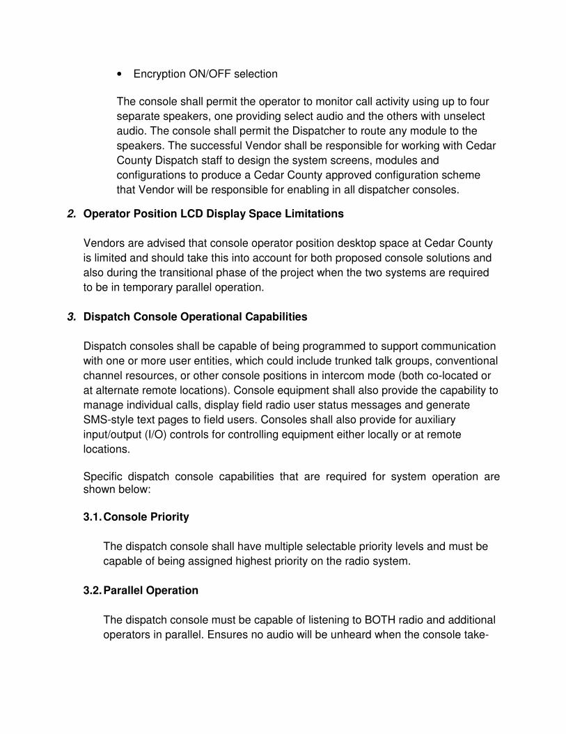
• Encryption ON/OFF selection
The console shall permit the operator to monitor call activity using up to four
separate speakers, one providing select audio and the others with unselect
audio. The console shall permit the Dispatcher to route any module to the
speakers. The successful Vendor shall be responsible for working with Cedar
County Dispatch staff to design the system screens, modules and
configurations to produce a Cedar County approved configuration scheme
that Vendor will be responsible for enabling in all dispatcher consoles.
2. Operator Position LCD Display Space Limitations
Vendors are advised that console operator position desktop space at Cedar County
is limited and should take this into account for both proposed console solutions and
also during the transitional phase of the project when the two systems are required
to be in temporary parallel operation.
3. Dispatch Console Operational Capabilities
Dispatch consoles shall be capable of being programmed to support communication
with one or more user entities, which could include trunked talk groups, conventional
channel resources, or other console positions in intercom mode (both co-located or
at alternate remote locations). Console equipment shall also provide the capability to
manage individual calls, display field radio user status messages and generate
SMS-style text pages to field users. Consoles shall also provide for auxiliary
input/output (I/O) controls for controlling equipment either locally or at remote
locations.
Specific dispatch console capabilities that are required for system operation are shown below:
3.1. Console Priority
The dispatch console shall have multiple selectable priority levels and must be
capable of being assigned highest priority on the radio system.
3.2. Parallel Operation
The dispatch console must be capable of listening to BOTH radio and additional
operators in parallel. Ensures no audio will be unheard when the console take-

over feature is enabled.
3.3. Radio Unit PTT ID
The dispatch console operator position shall display the radio subscriber unit ID
on its associated talk group during trunked operation and on a channel during
conventional operation. The ID shall be displayed in alphanumeric format based
on the assignment of names or aliases.
3.4. Encryption
The dispatch console system shall support end-to-end digital voice encryption.
This encryption shall be contiguous from the dispatch console to the user radio,
with no clear audio available at any intervening location. Vendor will detail their
process for clear Recording of encrypted traffic in the voice recorder.
3.5. Dispatcher Call Override
The dispatcher shall have the ability to interrupt a call in progress by members of
the same talk group, overriding the call so that all members present in the talk
group hear only the dispatcher.
3.6. Emergency Call Management
When a radio subscriber unit depresses a dedicated emergency button in a
standard talk group, the dispatch console position shall, upon receiving the call,
alert the operator with both an audible and visual alarm. The operator shall be
required to manually acknowledge the alarm in order to clear the audible alert
and visual indication. The dispatch console should allow options for defining the
alarm acknowledgement response sequence to clear a received emergency
alarm. The call history shall display the push-to-talk (PTT) ID and alias of the
unit declaring the emergency, along with date and time of the emergency call.
3.7. Patches
The console shall support patches, which involves temporarily combining two or
more talk groups (or channels in a conventional environment). A patch merges
the entities into a common group, such that each member hears every other
member. Each console shall be able to support up to five patches (talk groups
and/or conventional channels) each. All entities patched together shall be able to

communicate with one another. The console shall support pre- configured
patches or tactical, on-the-fly patch setups. Vendors shall note any limitation on
the number of talk groups or conventional channels that may be merged into a
single patched resource.
3.8. Simulselect
Consoles shall support simulselect, which involves temporarily summing two or
more modules at the console, rather than at the system level. Simulselect
merges the entities for the benefit of the dispatcher, but does not create a
common group. Only the dispatcher can hear all simulselect members. Each
console shall be able to support up to three simulselects. The dispatcher shall
be able to communicate with all entities contained in a single Simulselect. The
console shall support pre-configured simulselects. Vendors shall note any
limitation on the number of talk groups or conventional channels that may be
merged into a single simulselect resource, and the number of simulselects
available per console in their proposed system.
3.9. Call History Log
Received calls shall be recorded with a date and timestamp for immediate or
later review via a user-accessible and re-sizable window. The talk group and
individual identification of received calls shall be displayed with the alphanumeric
alias for ease of identification.
3.10. Central Console Management
The radio system dispatch equipment and database shall be capable of being
configured and managed from anywhere within the system management
network. Console resource management should be integrated with the overall
system network management approach.
3.11. Partitioning of Access to Console Configuration Parameters
The radio system dispatch architecture should be capable of supporting agency
and dispatch center partitioning of features and functionality to ensure that the
level of customization and modification to any dispatch console programmable
configurations can only be accomplished by a user with a corresponding level of
access.
This shall be implemented by various levels of logon access, whereby users are

assigned priorities. Levels of dispatch operating position configuration and editing are based upon assigned user priority validated during the logon process. Partitioned access shall extend to both console configurations and to audio resource management, as well as provisioning and configuration by technical support staff.
3.12. Link Failure
The console shall visually notify the dispatcher of any link failure between the
console position and the system central control equipment.
3.13. Conventional Operation
The console shall be able to control conventional control stations and repeaters
and provide the following functions:
• Control base station transmit/receive operation • Select the station’s transmit/receive frequency pair • Enable duplex base stations and voting comparators to repeat radio originated audio • Enable scan of selected channels in multi-channel control stations • Enable toggling between main base stations and standby base stations Vendors shall state how many simultaneous talk paths and receive audio sources the proposed consoles and supporting electronics allow.
3.14. Telephone Radio Headset Interface (TRHI)
Dispatch operator positions shall have a telephone radio headset interface
(TRHI) that provides telephone audio (separate 911 and administrative circuits)
as well as radio audio to provide a combined (mixed) audio source for operators.
4. Training
Vendor shall provide three (3) separate training classes on Console System to
accommodate multiple dispatcher shifts. Training shall be coordinated with Cedar
County at the appropriate time.

ANTENNAS, DUPLEXERS, AND TRANSMISSION LINES ANTENNAS All antennas must be checked for proper band and frequency range, along with critical parameters measured and recorded. All antennas must be either top-mounted on the water tower locations or side mounted on the communications towers using 3 foot or more side mounts made for the tower being used. Proper waterproofing of all outside connections is required. DUPLEXERS All duplexers must have 80 dB or greater isolation, must be of a BANDPASS-BAND REJECT type, and be swept with a tracking generator before installing into the system. TRANSMISSION LINES All transmission lines must be properly terminated and swept with a Frequency Domain Reflectometer to confirm that the lines and terminations are properly done. All inter-bay jumper cables must be double shielded and also swept to confirm proper operation and loss for each cable must be recorded.

GROUNDING AND LIGHTNING PROTECTION GROUNDING All equipment must be grounded. All lines must have lightning protectors on them, and the lightning protectors must be grounded. All transmission lines must have at least 2 ground kits on the lines, one at the top of the line near the antenna, and one at the bottom of the line just before it goes into the building or equipment cabinets. LIGHTNING PROTECTION All cables, power lines, control cables, or any other leads tied to the equipment must have the appropriate lightning protectors for the line being protected.

BACKUP POWER All sites must be provided with back-up power that is not relay switched, and the battery capacity must allow the stations to work for a minimum of 8 hours. All stations will switch to low power when on backup battery power. The batteries must have a life of 5 years or better.

FCC LICENSING The FCC Licensing for the new channels at the stated sites will be the responsibility of the successful bidder on this project. All fees and expenses for this part of the project must be included, as Cedar County is expecting to have no added expenses as part of this project. Since coordination expenses are the responsibility of the successful bidder, the vendor must know how many base stations and control stations, along with the pagers and mobile station are needing to be licensed and for how many channels. The details of the FCC application(s) will be handled at the appropriate time with the successful bidder on this project. In addition, the National Emergency Narrowband channels for VHF will be applied for and these channels will be programmed into all of the mobile and portable radios that can be operated in the narrowband mode as the other channels are programmed.

FACTORY OR VENDOR STAGING As this system is quite complex, Cedar County is insisting that the successful bidder of this project will assemble the entire system in the factory of the equipment manufacturer or in the vendors shop where all cables will be pre-made, levels set, and a full set of system documentation provided as part of the factory staging.

FINAL ACCEPTANCE TEST A final acceptance test (FAT) will be performed that tests the following functions of the new systems: NOTE: The FCC Licensing must start upon the award of the system to the successful bidder, so the FCC assigned frequencies for the two-way system should be set before this FAT is performed. Should the FCC Authorizations not be granted by the time that the FAT is to be performed; alternate channels will be found for the two-way system. The Paging channel remains the same as the current combined paging channel, but new locations do require the new FCC authorizations for the paging system channel at the new sites. PAGING A comprehensive FAT will be written that insures that all functions of a Tone and Voice simulcast paging system is working properly, and that all features and needs of Cedar County will be satisfied with the additions to the new system.

MANUALS There needs to be a full set of paper manuals for each piece of equipment at each site, and an additional 3 sets of manuals to be provided for each piece of equipment. In addition, there needs to be a system diagram available at each site and available in soft copy for maintenance and expansion purposes.
TRAINING There needs to be a training program that will meet the needs of the Cedar County PSAP schedule and provide onsite hands on training prior to the system going live. There will also need to be training support for issues that come up that were not covered during the training period for six months after the installation is complete.