
cdc_user
479
0-In ® CDC User Guide Software Version 10.0 February 2011 1995-2011 Mentor Graphics Corporation All rights reserved. This document contains information that is proprietary to Mentor Graphics Corporation. The original recipient of this document may duplicate this document in whole or in part for internal business purposes only, provided that this entire notice appears in all copies. In duplicating any part of this document, the recipient agrees to make every reasonable effort to prevent the unauthorized use and distribution of the proprietary information.
-
Upload
vinoth-kumar -
Category
Documents
-
view
1.933 -
download
20
Transcript of cdc_user

0-In® CDC User Guide
Software Version 10.0
February 2011
1995-2011 Mentor Graphics CorporationAll rights reserved.
This document contains information that is proprietary to Mentor Graphics Corporation. The original recipient of thisdocument may duplicate this document in whole or in part for internal business purposes only, provided that this entirenotice appears in all copies. In duplicating any part of this document, the recipient agrees to make every reasonableeffort to prevent the unauthorized use and distribution of the proprietary information.

This document is for information and instruction purposes. Mentor Graphics reserves the right to makechanges in specifications and other information contained in this publication without prior notice, and thereader should, in all cases, consult Mentor Graphics to determine whether any changes have beenmade.
The terms and conditions governing the sale and licensing of Mentor Graphics products are set forth inwritten agreements between Mentor Graphics and its customers. No representation or other affirmationof fact contained in this publication shall be deemed to be a warranty or give rise to any liability of MentorGraphics whatsoever.
MENTOR GRAPHICS MAKES NO WARRANTY OF ANY KIND WITH REGARD TO THIS MATERIALINCLUDING, BUT NOT LIMITED TO, THE IMPLIED WARRANTIES OF MERCHANTABILITY ANDFITNESS FOR A PARTICULAR PURPOSE.
MENTOR GRAPHICS SHALL NOT BE LIABLE FOR ANY INCIDENTAL, INDIRECT, SPECIAL, ORCONSEQUENTIAL DAMAGES WHATSOEVER (INCLUDING BUT NOT LIMITED TO LOST PROFITS)ARISING OUT OF OR RELATED TO THIS PUBLICATION OR THE INFORMATION CONTAINED IN IT,EVEN IF MENTOR GRAPHICS CORPORATION HAS BEEN ADVISED OF THE POSSIBILITY OFSUCH DAMAGES.
RESTRICTED RIGHTS LEGEND 03/97
U.S. Government Restricted Rights. The SOFTWARE and documentation have been developed entirelyat private expense and are commercial computer software provided with restricted rights. Use,duplication or disclosure by the U.S. Government or a U.S. Government subcontractor is subject to therestrictions set forth in the license agreement provided with the software pursuant to DFARS 227.7202-3(a) or as set forth in subparagraph (c)(1) and (2) of the Commercial Computer Software - RestrictedRights clause at FAR 52.227-19, as applicable.
Contractor/manufacturer is:Mentor Graphics Corporation
8005 S.W. Boeckman Road, Wilsonville, Oregon 97070-7777.Telephone: 503.685.7000
Toll-Free Telephone: 800.592.2210Website: www.mentor.com
SupportNet: supportnet.mentor.com/Send Feedback on Documentation: supportnet.mentor.com/user/feedback_form.cfm
TRADEMARKS: The trademarks, logos and service marks ("Marks") used herein are the property ofMentor Graphics Corporation or other third parties. No one is permitted to use these Marks without theprior written consent of Mentor Graphics or the respective third-party owner. The use herein of a third-party Mark is not an attempt to indicate Mentor Graphics as a source of a product, but is intended toindicate a product from, or associated with, a particular third party. A current list of Mentor Graphics’trademarks may be viewed at: www.mentor.com/terms_conditions/trademarks.cfm.

0-In CDC User Guide, v10.0 3February 2011
Table of Contents
Chapter 1Introduction. . . . . . . . . . . . . . . . . . . . . . . . . . . . . . . . . . . . . . . . . . . . . . . . . . . . . . . . . . . . . . . 15
0-In Advanced Functional Verification Manuals . . . . . . . . . . . . . . . . . . . . . . . . . . . . . . . . . 16Notational Conventions . . . . . . . . . . . . . . . . . . . . . . . . . . . . . . . . . . . . . . . . . . . . . . . . . . . . . 17Online Help . . . . . . . . . . . . . . . . . . . . . . . . . . . . . . . . . . . . . . . . . . . . . . . . . . . . . . . . . . . . . . 18Mentor Graphics Support. . . . . . . . . . . . . . . . . . . . . . . . . . . . . . . . . . . . . . . . . . . . . . . . . . . . 22
Chapter 2CDC Basics . . . . . . . . . . . . . . . . . . . . . . . . . . . . . . . . . . . . . . . . . . . . . . . . . . . . . . . . . . . . . . . 23
CDC Design Issues . . . . . . . . . . . . . . . . . . . . . . . . . . . . . . . . . . . . . . . . . . . . . . . . . . . . . . . . 24Clock Domains. . . . . . . . . . . . . . . . . . . . . . . . . . . . . . . . . . . . . . . . . . . . . . . . . . . . . . . . . . . . 25
Clock Groups . . . . . . . . . . . . . . . . . . . . . . . . . . . . . . . . . . . . . . . . . . . . . . . . . . . . . . . . . . . 25Metastability . . . . . . . . . . . . . . . . . . . . . . . . . . . . . . . . . . . . . . . . . . . . . . . . . . . . . . . . . . . . . 26
Metastability in Hardware. . . . . . . . . . . . . . . . . . . . . . . . . . . . . . . . . . . . . . . . . . . . . . . . . . 26Metastability in Standard RTL Simulation . . . . . . . . . . . . . . . . . . . . . . . . . . . . . . . . . . . . . 27CDC-FX Injected RTL Simulation. . . . . . . . . . . . . . . . . . . . . . . . . . . . . . . . . . . . . . . . . . . 29
Synchronizers. . . . . . . . . . . . . . . . . . . . . . . . . . . . . . . . . . . . . . . . . . . . . . . . . . . . . . . . . . . . . 30Control Signal Synchronizers. . . . . . . . . . . . . . . . . . . . . . . . . . . . . . . . . . . . . . . . . . . . . . 31Data Bus Synchronizers . . . . . . . . . . . . . . . . . . . . . . . . . . . . . . . . . . . . . . . . . . . . . . . . . . 32Ad Hoc Synchronizers . . . . . . . . . . . . . . . . . . . . . . . . . . . . . . . . . . . . . . . . . . . . . . . . . . . 34
Reconvergence. . . . . . . . . . . . . . . . . . . . . . . . . . . . . . . . . . . . . . . . . . . . . . . . . . . . . . . . . . . . 35Verifying Reconvergence . . . . . . . . . . . . . . . . . . . . . . . . . . . . . . . . . . . . . . . . . . . . . . . . . . 38
CDC Schemes . . . . . . . . . . . . . . . . . . . . . . . . . . . . . . . . . . . . . . . . . . . . . . . . . . . . . . . . . . . . 39Attributes of CDC Schemes . . . . . . . . . . . . . . . . . . . . . . . . . . . . . . . . . . . . . . . . . . . . . . . . 39
Severity. . . . . . . . . . . . . . . . . . . . . . . . . . . . . . . . . . . . . . . . . . . . . . . . . . . . . . . . . . . . . . . 39Promotion . . . . . . . . . . . . . . . . . . . . . . . . . . . . . . . . . . . . . . . . . . . . . . . . . . . . . . . . . . . . . 40
CDC Synchronization Schemes . . . . . . . . . . . . . . . . . . . . . . . . . . . . . . . . . . . . . . . . . . . . . 41Signals . . . . . . . . . . . . . . . . . . . . . . . . . . . . . . . . . . . . . . . . . . . . . . . . . . . . . . . . . . . . . . . 41Data. . . . . . . . . . . . . . . . . . . . . . . . . . . . . . . . . . . . . . . . . . . . . . . . . . . . . . . . . . . . . . . . . . 42Signal/Data . . . . . . . . . . . . . . . . . . . . . . . . . . . . . . . . . . . . . . . . . . . . . . . . . . . . . . . . . . . . 43
Schemes with Potential CDC Problems . . . . . . . . . . . . . . . . . . . . . . . . . . . . . . . . . . . . . . . 44Static CDC Analysis . . . . . . . . . . . . . . . . . . . . . . . . . . . . . . . . . . . . . . . . . . . . . . . . . . . . . . . 45
Formal CDC . . . . . . . . . . . . . . . . . . . . . . . . . . . . . . . . . . . . . . . . . . . . . . . . . . . . . . . . . . . . 46CDC Protocol Checker Promotion . . . . . . . . . . . . . . . . . . . . . . . . . . . . . . . . . . . . . . . . . . . 47
Formal Verification . . . . . . . . . . . . . . . . . . . . . . . . . . . . . . . . . . . . . . . . . . . . . . . . . . . . . . . . 49Simulation . . . . . . . . . . . . . . . . . . . . . . . . . . . . . . . . . . . . . . . . . . . . . . . . . . . . . . . . . . . . . . . 50Status Flags . . . . . . . . . . . . . . . . . . . . . . . . . . . . . . . . . . . . . . . . . . . . . . . . . . . . . . . . . . . . . . 53
Chapter 3Compilation . . . . . . . . . . . . . . . . . . . . . . . . . . . . . . . . . . . . . . . . . . . . . . . . . . . . . . . . . . . . . . . 55
1-Step Compilation . . . . . . . . . . . . . . . . . . . . . . . . . . . . . . . . . . . . . . . . . . . . . . . . . . . . . . . . 562-Step Compilation . . . . . . . . . . . . . . . . . . . . . . . . . . . . . . . . . . . . . . . . . . . . . . . . . . . . . . . . 57
Table of Contents
4February 2011
0-In CDC User Guide, v10.0
Step 1: Compile and Maintain Design Libraries. . . . . . . . . . . . . . . . . . . . . . . . . . . . . . . . . 57Preparing a Design Library . . . . . . . . . . . . . . . . . . . . . . . . . . . . . . . . . . . . . . . . . . . . . . . 57Compiling Design Files . . . . . . . . . . . . . . . . . . . . . . . . . . . . . . . . . . . . . . . . . . . . . . . . . . 59Resource Libraries . . . . . . . . . . . . . . . . . . . . . . . . . . . . . . . . . . . . . . . . . . . . . . . . . . . . . . 60
Step 2: Run CDC Compilation . . . . . . . . . . . . . . . . . . . . . . . . . . . . . . . . . . . . . . . . . . . . . . 64cdc: Clock Domain Crossing Analyzer . . . . . . . . . . . . . . . . . . . . . . . . . . . . . . . . . . . . . . 64
SDC Data . . . . . . . . . . . . . . . . . . . . . . . . . . . . . . . . . . . . . . . . . . . . . . . . . . . . . . . . . . . . . . . . 66Importing an SDC File . . . . . . . . . . . . . . . . . . . . . . . . . . . . . . . . . . . . . . . . . . . . . . . . . . . . 66Exporting SDC Data . . . . . . . . . . . . . . . . . . . . . . . . . . . . . . . . . . . . . . . . . . . . . . . . . . . . . . 67
Design Style Restrictions. . . . . . . . . . . . . . . . . . . . . . . . . . . . . . . . . . . . . . . . . . . . . . . . . . . . 69Verilog . . . . . . . . . . . . . . . . . . . . . . . . . . . . . . . . . . . . . . . . . . . . . . . . . . . . . . . . . . . . . . . . 72VHDL . . . . . . . . . . . . . . . . . . . . . . . . . . . . . . . . . . . . . . . . . . . . . . . . . . . . . . . . . . . . . . . . . 75
Binding to Verilog Design Units . . . . . . . . . . . . . . . . . . . . . . . . . . . . . . . . . . . . . . . . . . . 840-In Directives Restrictions . . . . . . . . . . . . . . . . . . . . . . . . . . . . . . . . . . . . . . . . . . . . . . . . 85
Chapter 4CDC Analysis . . . . . . . . . . . . . . . . . . . . . . . . . . . . . . . . . . . . . . . . . . . . . . . . . . . . . . . . . . . . . 87
CDC Analysis Tools . . . . . . . . . . . . . . . . . . . . . . . . . . . . . . . . . . . . . . . . . . . . . . . . . . . . . . . 880in_cdc: GUI Debug Mode. . . . . . . . . . . . . . . . . . . . . . . . . . . . . . . . . . . . . . . . . . . . . . . . . 880in_cdc: GUI Project Mode . . . . . . . . . . . . . . . . . . . . . . . . . . . . . . . . . . . . . . . . . . . . . . . . 91
Static CDC Verification Flow . . . . . . . . . . . . . . . . . . . . . . . . . . . . . . . . . . . . . . . . . . . . . . . . 92Phase 1. Compiling the Design. . . . . . . . . . . . . . . . . . . . . . . . . . . . . . . . . . . . . . . . . . . . . . 93Phase 2: Analyzing Clock Domains . . . . . . . . . . . . . . . . . . . . . . . . . . . . . . . . . . . . . . . . . . 93Phase 3: Compiling CDC Logic . . . . . . . . . . . . . . . . . . . . . . . . . . . . . . . . . . . . . . . . . . . . . 96Phase 4: Running GUI Debug. . . . . . . . . . . . . . . . . . . . . . . . . . . . . . . . . . . . . . . . . . . . . . . 96
Dynamic CDC Verification Flow . . . . . . . . . . . . . . . . . . . . . . . . . . . . . . . . . . . . . . . . . . . . . 104CDC Protocol Analysis. . . . . . . . . . . . . . . . . . . . . . . . . . . . . . . . . . . . . . . . . . . . . . . . . . . . 104
0-In Formal Verification. . . . . . . . . . . . . . . . . . . . . . . . . . . . . . . . . . . . . . . . . . . . . . . . . . 105Simulation with CDC Protocol Assertions. . . . . . . . . . . . . . . . . . . . . . . . . . . . . . . . . . . . 107
CDC-FX Metastability Analysis. . . . . . . . . . . . . . . . . . . . . . . . . . . . . . . . . . . . . . . . . . . . . 111Running Simulation with CDC-FX Metastability Injection. . . . . . . . . . . . . . . . . . . . . . . 112
Simulation Arguments . . . . . . . . . . . . . . . . . . . . . . . . . . . . . . . . . . . . . . . . . . . . . . . . . . . . 113Compiling with ccl for Simulation . . . . . . . . . . . . . . . . . . . . . . . . . . . . . . . . . . . . . . . . . . . 115
Hierarchical CDC Analysis . . . . . . . . . . . . . . . . . . . . . . . . . . . . . . . . . . . . . . . . . . . . . . . . . . 118Basic Hierarchical CDC Flow . . . . . . . . . . . . . . . . . . . . . . . . . . . . . . . . . . . . . . . . . . . . . . 119Hierarchical CDC Scripts . . . . . . . . . . . . . . . . . . . . . . . . . . . . . . . . . . . . . . . . . . . . . . . . . . 124Waivers . . . . . . . . . . . . . . . . . . . . . . . . . . . . . . . . . . . . . . . . . . . . . . . . . . . . . . . . . . . . . . . . 127Variations on the Hierarchical CDC Flow . . . . . . . . . . . . . . . . . . . . . . . . . . . . . . . . . . . . . 129
Heterogeneous Instances of Blocks . . . . . . . . . . . . . . . . . . . . . . . . . . . . . . . . . . . . . . . . . 129Control File Models . . . . . . . . . . . . . . . . . . . . . . . . . . . . . . . . . . . . . . . . . . . . . . . . . . . . . 131
Modal CDC Analysis. . . . . . . . . . . . . . . . . . . . . . . . . . . . . . . . . . . . . . . . . . . . . . . . . . . . . . . 133Use Model. . . . . . . . . . . . . . . . . . . . . . . . . . . . . . . . . . . . . . . . . . . . . . . . . . . . . . . . . . . . . . 134
Specify Modes (optional) . . . . . . . . . . . . . . . . . . . . . . . . . . . . . . . . . . . . . . . . . . . . . . . . . 135Report Mode Runs . . . . . . . . . . . . . . . . . . . . . . . . . . . . . . . . . . . . . . . . . . . . . . . . . . . . . . 135Mode Verification and Coverage Reporting . . . . . . . . . . . . . . . . . . . . . . . . . . . . . . . . . . 136Individual Mode Analysis . . . . . . . . . . . . . . . . . . . . . . . . . . . . . . . . . . . . . . . . . . . . . . . . 138Viewing Results . . . . . . . . . . . . . . . . . . . . . . . . . . . . . . . . . . . . . . . . . . . . . . . . . . . . . . . . 138
Examples. . . . . . . . . . . . . . . . . . . . . . . . . . . . . . . . . . . . . . . . . . . . . . . . . . . . . . . . . . . . . . . 144Viewing Incomplete CDC Runs . . . . . . . . . . . . . . . . . . . . . . . . . . . . . . . . . . . . . . . . . . . . . 146
Table of Contents
0-In CDC User Guide, v10.0 5February 2011
CDC Analysis of FPGAs . . . . . . . . . . . . . . . . . . . . . . . . . . . . . . . . . . . . . . . . . . . . . . . . . . . . 149Phase 1: Compiling the FPGA Source Libraries . . . . . . . . . . . . . . . . . . . . . . . . . . . . . . . . 149
Xilinx . . . . . . . . . . . . . . . . . . . . . . . . . . . . . . . . . . . . . . . . . . . . . . . . . . . . . . . . . . . . . . . . 149Altera . . . . . . . . . . . . . . . . . . . . . . . . . . . . . . . . . . . . . . . . . . . . . . . . . . . . . . . . . . . . . . . . 151Logical-physical Library Mappings . . . . . . . . . . . . . . . . . . . . . . . . . . . . . . . . . . . . . . . . . 151
Phase 2: Compiling the Design. . . . . . . . . . . . . . . . . . . . . . . . . . . . . . . . . . . . . . . . . . . . . . 152Phase 3: Compiling a CDC Model of the Design . . . . . . . . . . . . . . . . . . . . . . . . . . . . . . . . 152Phase 4: Running GUI Debug. . . . . . . . . . . . . . . . . . . . . . . . . . . . . . . . . . . . . . . . . . . . . . . 157
Chapter 5CDC-FX Metastability Injection . . . . . . . . . . . . . . . . . . . . . . . . . . . . . . . . . . . . . . . . . . . . . . 159
Specifying Metastability Windows . . . . . . . . . . . . . . . . . . . . . . . . . . . . . . . . . . . . . . . . . . . . 160Metastability Windows Usage . . . . . . . . . . . . . . . . . . . . . . . . . . . . . . . . . . . . . . . . . . . . . . 161
Running CDC-FX . . . . . . . . . . . . . . . . . . . . . . . . . . . . . . . . . . . . . . . . . . . . . . . . . . . . . . . . . 165set_cdc_fx_check . . . . . . . . . . . . . . . . . . . . . . . . . . . . . . . . . . . . . . . . . . . . . . . . . . . . . . . 165
Running Metastability-injected Simulation . . . . . . . . . . . . . . . . . . . . . . . . . . . . . . . . . . . . . . 169Simulation Arguments . . . . . . . . . . . . . . . . . . . . . . . . . . . . . . . . . . . . . . . . . . . . . . . . . . . . 170CDC-FX PLI Functions . . . . . . . . . . . . . . . . . . . . . . . . . . . . . . . . . . . . . . . . . . . . . . . . . . . 171Verilog Glue Logic Option Impact . . . . . . . . . . . . . . . . . . . . . . . . . . . . . . . . . . . . . . . . . . . 171VHDL Glue Logic Option Impact . . . . . . . . . . . . . . . . . . . . . . . . . . . . . . . . . . . . . . . . . . . 173
Metastability Injector Simulation Methodology . . . . . . . . . . . . . . . . . . . . . . . . . . . . . . . . . . 174Assertion Violations . . . . . . . . . . . . . . . . . . . . . . . . . . . . . . . . . . . . . . . . . . . . . . . . . . . . . . 174
Chapter 6Command Reference . . . . . . . . . . . . . . . . . . . . . . . . . . . . . . . . . . . . . . . . . . . . . . . . . . . . . . . 177
CDC Schemes . . . . . . . . . . . . . . . . . . . . . . . . . . . . . . . . . . . . . . . . . . . . . . . . . . . . . . . . . . . . 179async_reset . . . . . . . . . . . . . . . . . . . . . . . . . . . . . . . . . . . . . . . . . . . . . . . . . . . . . . . . . . . . . 181async_reset_no_sync. . . . . . . . . . . . . . . . . . . . . . . . . . . . . . . . . . . . . . . . . . . . . . . . . . . . . . 184blackbox . . . . . . . . . . . . . . . . . . . . . . . . . . . . . . . . . . . . . . . . . . . . . . . . . . . . . . . . . . . . . . . 186bus_custom_sync . . . . . . . . . . . . . . . . . . . . . . . . . . . . . . . . . . . . . . . . . . . . . . . . . . . . . . . . 189bus_dff_sync_gated_clk . . . . . . . . . . . . . . . . . . . . . . . . . . . . . . . . . . . . . . . . . . . . . . . . . . . 191bus_four_latch. . . . . . . . . . . . . . . . . . . . . . . . . . . . . . . . . . . . . . . . . . . . . . . . . . . . . . . . . . . 193bus_shift_reg. . . . . . . . . . . . . . . . . . . . . . . . . . . . . . . . . . . . . . . . . . . . . . . . . . . . . . . . . . . . 195bus_two_dff . . . . . . . . . . . . . . . . . . . . . . . . . . . . . . . . . . . . . . . . . . . . . . . . . . . . . . . . . . . . 197bus_two_dff_phase . . . . . . . . . . . . . . . . . . . . . . . . . . . . . . . . . . . . . . . . . . . . . . . . . . . . . . . 199combo_logic . . . . . . . . . . . . . . . . . . . . . . . . . . . . . . . . . . . . . . . . . . . . . . . . . . . . . . . . . . . . 201custom_sync . . . . . . . . . . . . . . . . . . . . . . . . . . . . . . . . . . . . . . . . . . . . . . . . . . . . . . . . . . . . 203custom_sync_with_crossing . . . . . . . . . . . . . . . . . . . . . . . . . . . . . . . . . . . . . . . . . . . . . . . . 205dff_sync_gated_clk . . . . . . . . . . . . . . . . . . . . . . . . . . . . . . . . . . . . . . . . . . . . . . . . . . . . . . . 207dmux . . . . . . . . . . . . . . . . . . . . . . . . . . . . . . . . . . . . . . . . . . . . . . . . . . . . . . . . . . . . . . . . . . 208fanin_different_clks . . . . . . . . . . . . . . . . . . . . . . . . . . . . . . . . . . . . . . . . . . . . . . . . . . . . . . 210fifo. . . . . . . . . . . . . . . . . . . . . . . . . . . . . . . . . . . . . . . . . . . . . . . . . . . . . . . . . . . . . . . . . . . . 213four_latch . . . . . . . . . . . . . . . . . . . . . . . . . . . . . . . . . . . . . . . . . . . . . . . . . . . . . . . . . . . . . . 218handshake . . . . . . . . . . . . . . . . . . . . . . . . . . . . . . . . . . . . . . . . . . . . . . . . . . . . . . . . . . . . . . 220memory_sync . . . . . . . . . . . . . . . . . . . . . . . . . . . . . . . . . . . . . . . . . . . . . . . . . . . . . . . . . . . 223multi_bits . . . . . . . . . . . . . . . . . . . . . . . . . . . . . . . . . . . . . . . . . . . . . . . . . . . . . . . . . . . . . . 225multi_sync_mux_select. . . . . . . . . . . . . . . . . . . . . . . . . . . . . . . . . . . . . . . . . . . . . . . . . . . . 227no_sync . . . . . . . . . . . . . . . . . . . . . . . . . . . . . . . . . . . . . . . . . . . . . . . . . . . . . . . . . . . . . . . . 229port_constraint_mismatch. . . . . . . . . . . . . . . . . . . . . . . . . . . . . . . . . . . . . . . . . . . . . . . . . . 231

Table of Contents
6February 2011
0-In CDC User Guide, v10.0
pulse_sync. . . . . . . . . . . . . . . . . . . . . . . . . . . . . . . . . . . . . . . . . . . . . . . . . . . . . . . . . . . . . . 233reconvergence . . . . . . . . . . . . . . . . . . . . . . . . . . . . . . . . . . . . . . . . . . . . . . . . . . . . . . . . . . . 235redundant. . . . . . . . . . . . . . . . . . . . . . . . . . . . . . . . . . . . . . . . . . . . . . . . . . . . . . . . . . . . . . . 238series_redundant . . . . . . . . . . . . . . . . . . . . . . . . . . . . . . . . . . . . . . . . . . . . . . . . . . . . . . . . . 240shift_reg . . . . . . . . . . . . . . . . . . . . . . . . . . . . . . . . . . . . . . . . . . . . . . . . . . . . . . . . . . . . . . . 242simple_dmux. . . . . . . . . . . . . . . . . . . . . . . . . . . . . . . . . . . . . . . . . . . . . . . . . . . . . . . . . . . . 244single_source_reconvergence . . . . . . . . . . . . . . . . . . . . . . . . . . . . . . . . . . . . . . . . . . . . . . . 246two_dff . . . . . . . . . . . . . . . . . . . . . . . . . . . . . . . . . . . . . . . . . . . . . . . . . . . . . . . . . . . . . . . . 251two_dff_phase. . . . . . . . . . . . . . . . . . . . . . . . . . . . . . . . . . . . . . . . . . . . . . . . . . . . . . . . . . . 253
Global Directives . . . . . . . . . . . . . . . . . . . . . . . . . . . . . . . . . . . . . . . . . . . . . . . . . . . . . . . . . . 2540-In Comments . . . . . . . . . . . . . . . . . . . . . . . . . . . . . . . . . . . . . . . . . . . . . . . . . . . . . . . . . . 2540-In Primitives . . . . . . . . . . . . . . . . . . . . . . . . . . . . . . . . . . . . . . . . . . . . . . . . . . . . . . . . . . 255Hierarchical Paths . . . . . . . . . . . . . . . . . . . . . . . . . . . . . . . . . . . . . . . . . . . . . . . . . . . . . . . . 257Wildcards in Directive Arguments . . . . . . . . . . . . . . . . . . . . . . . . . . . . . . . . . . . . . . . . . . . 257Directive Order . . . . . . . . . . . . . . . . . . . . . . . . . . . . . . . . . . . . . . . . . . . . . . . . . . . . . . . . . . 259
Directives for CDC Analysis . . . . . . . . . . . . . . . . . . . . . . . . . . . . . . . . . . . . . . . . . . . . . . . . . 260set_black_box . . . . . . . . . . . . . . . . . . . . . . . . . . . . . . . . . . . . . . . . . . . . . . . . . . . . . . . . . . . 262set_cdc_clock . . . . . . . . . . . . . . . . . . . . . . . . . . . . . . . . . . . . . . . . . . . . . . . . . . . . . . . . . . . 263set_cdc_fifo. . . . . . . . . . . . . . . . . . . . . . . . . . . . . . . . . . . . . . . . . . . . . . . . . . . . . . . . . . . . . 266set_cdc_fifo_preference . . . . . . . . . . . . . . . . . . . . . . . . . . . . . . . . . . . . . . . . . . . . . . . . . . . 267set_cdc_fx_check . . . . . . . . . . . . . . . . . . . . . . . . . . . . . . . . . . . . . . . . . . . . . . . . . . . . . . . . 268set_cdc_fx_metastability_window . . . . . . . . . . . . . . . . . . . . . . . . . . . . . . . . . . . . . . . . . . . 269set_cdc_fx_timescale . . . . . . . . . . . . . . . . . . . . . . . . . . . . . . . . . . . . . . . . . . . . . . . . . . . . . 270set_cdc_handshake_preference. . . . . . . . . . . . . . . . . . . . . . . . . . . . . . . . . . . . . . . . . . . . . . 271set_cdc_hier_preference . . . . . . . . . . . . . . . . . . . . . . . . . . . . . . . . . . . . . . . . . . . . . . . . . . . 272set_cdc_port_constraint . . . . . . . . . . . . . . . . . . . . . . . . . . . . . . . . . . . . . . . . . . . . . . . . . . . 273set_cdc_port_domain . . . . . . . . . . . . . . . . . . . . . . . . . . . . . . . . . . . . . . . . . . . . . . . . . . . . . 276set_cdc_preference . . . . . . . . . . . . . . . . . . . . . . . . . . . . . . . . . . . . . . . . . . . . . . . . . . . . . . . 283set_cdc_protocol . . . . . . . . . . . . . . . . . . . . . . . . . . . . . . . . . . . . . . . . . . . . . . . . . . . . . . . . . 289set_cdc_reconvergence . . . . . . . . . . . . . . . . . . . . . . . . . . . . . . . . . . . . . . . . . . . . . . . . . . . . 291set_cdc_report . . . . . . . . . . . . . . . . . . . . . . . . . . . . . . . . . . . . . . . . . . . . . . . . . . . . . . . . . . . 293set_cdc_signal . . . . . . . . . . . . . . . . . . . . . . . . . . . . . . . . . . . . . . . . . . . . . . . . . . . . . . . . . . . 299set_cdc_synchronizer . . . . . . . . . . . . . . . . . . . . . . . . . . . . . . . . . . . . . . . . . . . . . . . . . . . . . 302set_constant. . . . . . . . . . . . . . . . . . . . . . . . . . . . . . . . . . . . . . . . . . . . . . . . . . . . . . . . . . . . . 305set_constant_propagation . . . . . . . . . . . . . . . . . . . . . . . . . . . . . . . . . . . . . . . . . . . . . . . . . . 306set_memory. . . . . . . . . . . . . . . . . . . . . . . . . . . . . . . . . . . . . . . . . . . . . . . . . . . . . . . . . . . . . 308set_mode . . . . . . . . . . . . . . . . . . . . . . . . . . . . . . . . . . . . . . . . . . . . . . . . . . . . . . . . . . . . . . . 310set_mode_control . . . . . . . . . . . . . . . . . . . . . . . . . . . . . . . . . . . . . . . . . . . . . . . . . . . . . . . . 311set_reset. . . . . . . . . . . . . . . . . . . . . . . . . . . . . . . . . . . . . . . . . . . . . . . . . . . . . . . . . . . . . . . . 312
Directives for Checker Generation . . . . . . . . . . . . . . . . . . . . . . . . . . . . . . . . . . . . . . . . . . . . 313checker_firing_keyword . . . . . . . . . . . . . . . . . . . . . . . . . . . . . . . . . . . . . . . . . . . . . . . . . . . 314create_wire . . . . . . . . . . . . . . . . . . . . . . . . . . . . . . . . . . . . . . . . . . . . . . . . . . . . . . . . . . . . . 315default_reset . . . . . . . . . . . . . . . . . . . . . . . . . . . . . . . . . . . . . . . . . . . . . . . . . . . . . . . . . . . . 316disable_checker. . . . . . . . . . . . . . . . . . . . . . . . . . . . . . . . . . . . . . . . . . . . . . . . . . . . . . . . . . 318disable_used . . . . . . . . . . . . . . . . . . . . . . . . . . . . . . . . . . . . . . . . . . . . . . . . . . . . . . . . . . . . 319exclude_checker . . . . . . . . . . . . . . . . . . . . . . . . . . . . . . . . . . . . . . . . . . . . . . . . . . . . . . . . . 320include_checker . . . . . . . . . . . . . . . . . . . . . . . . . . . . . . . . . . . . . . . . . . . . . . . . . . . . . . . . . 321set_checker_action . . . . . . . . . . . . . . . . . . . . . . . . . . . . . . . . . . . . . . . . . . . . . . . . . . . . . . . 322set_severity . . . . . . . . . . . . . . . . . . . . . . . . . . . . . . . . . . . . . . . . . . . . . . . . . . . . . . . . . . . . . 323

Table of Contents
0-In CDC User Guide, v10.0 7February 2011
use_synthesis_case_directives . . . . . . . . . . . . . . . . . . . . . . . . . . . . . . . . . . . . . . . . . . . . . . 324Shell Commands . . . . . . . . . . . . . . . . . . . . . . . . . . . . . . . . . . . . . . . . . . . . . . . . . . . . . . . . . . 325
vlib . . . . . . . . . . . . . . . . . . . . . . . . . . . . . . . . . . . . . . . . . . . . . . . . . . . . . . . . . . . . . . . . . . . 326vmap . . . . . . . . . . . . . . . . . . . . . . . . . . . . . . . . . . . . . . . . . . . . . . . . . . . . . . . . . . . . . . . . . . 327vcom . . . . . . . . . . . . . . . . . . . . . . . . . . . . . . . . . . . . . . . . . . . . . . . . . . . . . . . . . . . . . . . . . . 330vlog . . . . . . . . . . . . . . . . . . . . . . . . . . . . . . . . . . . . . . . . . . . . . . . . . . . . . . . . . . . . . . . . . . . 334verror. . . . . . . . . . . . . . . . . . . . . . . . . . . . . . . . . . . . . . . . . . . . . . . . . . . . . . . . . . . . . . . . . . 340vdir . . . . . . . . . . . . . . . . . . . . . . . . . . . . . . . . . . . . . . . . . . . . . . . . . . . . . . . . . . . . . . . . . . . 342vdel . . . . . . . . . . . . . . . . . . . . . . . . . . . . . . . . . . . . . . . . . . . . . . . . . . . . . . . . . . . . . . . . . . . 3450in . . . . . . . . . . . . . . . . . . . . . . . . . . . . . . . . . . . . . . . . . . . . . . . . . . . . . . . . . . . . . . . . . . . . 3470in_cdc . . . . . . . . . . . . . . . . . . . . . . . . . . . . . . . . . . . . . . . . . . . . . . . . . . . . . . . . . . . . . . . . 3490in_db2ucdb . . . . . . . . . . . . . . . . . . . . . . . . . . . . . . . . . . . . . . . . . . . . . . . . . . . . . . . . . . . . 353
0in Shell Commands . . . . . . . . . . . . . . . . . . . . . . . . . . . . . . . . . . . . . . . . . . . . . . . . . . . . . . . 358cdc . . . . . . . . . . . . . . . . . . . . . . . . . . . . . . . . . . . . . . . . . . . . . . . . . . . . . . . . . . . . . . . . . . . . 359cwhelp . . . . . . . . . . . . . . . . . . . . . . . . . . . . . . . . . . . . . . . . . . . . . . . . . . . . . . . . . . . . . . . . . 373
Protocol/FX Checkers . . . . . . . . . . . . . . . . . . . . . . . . . . . . . . . . . . . . . . . . . . . . . . . . . . . . . . 375Standard Options. . . . . . . . . . . . . . . . . . . . . . . . . . . . . . . . . . . . . . . . . . . . . . . . . . . . . . . . . 375cdc_dsel. . . . . . . . . . . . . . . . . . . . . . . . . . . . . . . . . . . . . . . . . . . . . . . . . . . . . . . . . . . . . . . . 377cdc_fifo . . . . . . . . . . . . . . . . . . . . . . . . . . . . . . . . . . . . . . . . . . . . . . . . . . . . . . . . . . . . . . . . 381cdc_glitch . . . . . . . . . . . . . . . . . . . . . . . . . . . . . . . . . . . . . . . . . . . . . . . . . . . . . . . . . . . . . . 385cdc_hamming_distance_one . . . . . . . . . . . . . . . . . . . . . . . . . . . . . . . . . . . . . . . . . . . . . . . . 387cdc_handshake_data . . . . . . . . . . . . . . . . . . . . . . . . . . . . . . . . . . . . . . . . . . . . . . . . . . . . . . 390cdc_sample . . . . . . . . . . . . . . . . . . . . . . . . . . . . . . . . . . . . . . . . . . . . . . . . . . . . . . . . . . . . . 398cdc_sync . . . . . . . . . . . . . . . . . . . . . . . . . . . . . . . . . . . . . . . . . . . . . . . . . . . . . . . . . . . . . . . 401cdc_fx . . . . . . . . . . . . . . . . . . . . . . . . . . . . . . . . . . . . . . . . . . . . . . . . . . . . . . . . . . . . . . . . . 404cdc_custom_fx . . . . . . . . . . . . . . . . . . . . . . . . . . . . . . . . . . . . . . . . . . . . . . . . . . . . . . . . . . 408
Chapter 7GUI Reference. . . . . . . . . . . . . . . . . . . . . . . . . . . . . . . . . . . . . . . . . . . . . . . . . . . . . . . . . . . . . 411
GUI Main Window . . . . . . . . . . . . . . . . . . . . . . . . . . . . . . . . . . . . . . . . . . . . . . . . . . . . . . . . 411GUI Basics . . . . . . . . . . . . . . . . . . . . . . . . . . . . . . . . . . . . . . . . . . . . . . . . . . . . . . . . . . . . . 411Window Layouts. . . . . . . . . . . . . . . . . . . . . . . . . . . . . . . . . . . . . . . . . . . . . . . . . . . . . . . . . 415
Analysis Windows . . . . . . . . . . . . . . . . . . . . . . . . . . . . . . . . . . . . . . . . . . . . . . . . . . . . . . . . . 418Errors/Warnings Window . . . . . . . . . . . . . . . . . . . . . . . . . . . . . . . . . . . . . . . . . . . . . . . . . . 418CDC Checks Viewer. . . . . . . . . . . . . . . . . . . . . . . . . . . . . . . . . . . . . . . . . . . . . . . . . . . . . . 419
Debug Windows. . . . . . . . . . . . . . . . . . . . . . . . . . . . . . . . . . . . . . . . . . . . . . . . . . . . . . . . . . . 422Details Window . . . . . . . . . . . . . . . . . . . . . . . . . . . . . . . . . . . . . . . . . . . . . . . . . . . . . . . . . 422Objects Window . . . . . . . . . . . . . . . . . . . . . . . . . . . . . . . . . . . . . . . . . . . . . . . . . . . . . . . . . 423Log/Report Browsers . . . . . . . . . . . . . . . . . . . . . . . . . . . . . . . . . . . . . . . . . . . . . . . . . . . . . 424
Schematics Viewer. . . . . . . . . . . . . . . . . . . . . . . . . . . . . . . . . . . . . . . . . . . . . . . . . . . . . . . . . 426Expanding Logic in the Schematic View . . . . . . . . . . . . . . . . . . . . . . . . . . . . . . . . . . . . . . 426Zooming the Schematic View In or Out . . . . . . . . . . . . . . . . . . . . . . . . . . . . . . . . . . . . . . . 428
Source Code Editor . . . . . . . . . . . . . . . . . . . . . . . . . . . . . . . . . . . . . . . . . . . . . . . . . . . . . . . . 429Waveform Viewer . . . . . . . . . . . . . . . . . . . . . . . . . . . . . . . . . . . . . . . . . . . . . . . . . . . . . . . . . 430
Saving Waveforms and Waveform Formats . . . . . . . . . . . . . . . . . . . . . . . . . . . . . . . . . . 430Loading Waveforms and Waveform Formats . . . . . . . . . . . . . . . . . . . . . . . . . . . . . . . . . 430Zooming the Wave View In or Out . . . . . . . . . . . . . . . . . . . . . . . . . . . . . . . . . . . . . . . . . 431Capturing Zoomed/Scrolled Views as Bookmarks . . . . . . . . . . . . . . . . . . . . . . . . . . . . . 432

Table of Contents
8February 2011
0-In CDC User Guide, v10.0
Selecting Multiple Signals for Format Operations. . . . . . . . . . . . . . . . . . . . . . . . . . . . . . 433Changing the Display Properties of Signals . . . . . . . . . . . . . . . . . . . . . . . . . . . . . . . . . . . 433Changing the Signal Pathname Properties . . . . . . . . . . . . . . . . . . . . . . . . . . . . . . . . . . . . 433Adding Signals . . . . . . . . . . . . . . . . . . . . . . . . . . . . . . . . . . . . . . . . . . . . . . . . . . . . . . . . . 434Removing Signals. . . . . . . . . . . . . . . . . . . . . . . . . . . . . . . . . . . . . . . . . . . . . . . . . . . . . . . 435Organizing Signals . . . . . . . . . . . . . . . . . . . . . . . . . . . . . . . . . . . . . . . . . . . . . . . . . . . . . . 435Using Multiple Window Panes. . . . . . . . . . . . . . . . . . . . . . . . . . . . . . . . . . . . . . . . . . . . . 436Using Cursors to Analyze Events. . . . . . . . . . . . . . . . . . . . . . . . . . . . . . . . . . . . . . . . . . . 437Capturing a Waveform’s Image . . . . . . . . . . . . . . . . . . . . . . . . . . . . . . . . . . . . . . . . . . . . 438Adding a Source Code Variable to a Waveform . . . . . . . . . . . . . . . . . . . . . . . . . . . . . . . 438Annotating Source Code with Variables’ Values. . . . . . . . . . . . . . . . . . . . . . . . . . . . . . . 438
Project Mode Windows . . . . . . . . . . . . . . . . . . . . . . . . . . . . . . . . . . . . . . . . . . . . . . . . . . . . . 440Project Window . . . . . . . . . . . . . . . . . . . . . . . . . . . . . . . . . . . . . . . . . . . . . . . . . . . . . . . . . 440Design Window . . . . . . . . . . . . . . . . . . . . . . . . . . . . . . . . . . . . . . . . . . . . . . . . . . . . . . . . . 441Modules Window . . . . . . . . . . . . . . . . . . . . . . . . . . . . . . . . . . . . . . . . . . . . . . . . . . . . . . . . 442Clocks Window. . . . . . . . . . . . . . . . . . . . . . . . . . . . . . . . . . . . . . . . . . . . . . . . . . . . . . . . . . 443Directives Window . . . . . . . . . . . . . . . . . . . . . . . . . . . . . . . . . . . . . . . . . . . . . . . . . . . . . . . 444
Chapter 8Reports/Logs Reference . . . . . . . . . . . . . . . . . . . . . . . . . . . . . . . . . . . . . . . . . . . . . . . . . . . . . 445
CDC Design Report . . . . . . . . . . . . . . . . . . . . . . . . . . . . . . . . . . . . . . . . . . . . . . . . . . . . . . . . 446Clock Group Summary . . . . . . . . . . . . . . . . . . . . . . . . . . . . . . . . . . . . . . . . . . . . . . . . . . . . 446User-Specified Clock Groups . . . . . . . . . . . . . . . . . . . . . . . . . . . . . . . . . . . . . . . . . . . . . . . 447Inferred Clock Groups . . . . . . . . . . . . . . . . . . . . . . . . . . . . . . . . . . . . . . . . . . . . . . . . . . . . 447Ignored Clock Groups. . . . . . . . . . . . . . . . . . . . . . . . . . . . . . . . . . . . . . . . . . . . . . . . . . . . . 449General Design Information . . . . . . . . . . . . . . . . . . . . . . . . . . . . . . . . . . . . . . . . . . . . . . . . 449Detailed Design Information. . . . . . . . . . . . . . . . . . . . . . . . . . . . . . . . . . . . . . . . . . . . . . . . 449Port Domain Information . . . . . . . . . . . . . . . . . . . . . . . . . . . . . . . . . . . . . . . . . . . . . . . . . . 450Mode Information . . . . . . . . . . . . . . . . . . . . . . . . . . . . . . . . . . . . . . . . . . . . . . . . . . . . . . . . 451
Clock Domain Crossing Report . . . . . . . . . . . . . . . . . . . . . . . . . . . . . . . . . . . . . . . . . . . . . . . 452CDC Summary . . . . . . . . . . . . . . . . . . . . . . . . . . . . . . . . . . . . . . . . . . . . . . . . . . . . . . . . . . 452CDC Promotion Summary . . . . . . . . . . . . . . . . . . . . . . . . . . . . . . . . . . . . . . . . . . . . . . . . . 453Violations . . . . . . . . . . . . . . . . . . . . . . . . . . . . . . . . . . . . . . . . . . . . . . . . . . . . . . . . . . . . . . 453Cautions . . . . . . . . . . . . . . . . . . . . . . . . . . . . . . . . . . . . . . . . . . . . . . . . . . . . . . . . . . . . . . . 454Evaluations . . . . . . . . . . . . . . . . . . . . . . . . . . . . . . . . . . . . . . . . . . . . . . . . . . . . . . . . . . . . . 455Waived . . . . . . . . . . . . . . . . . . . . . . . . . . . . . . . . . . . . . . . . . . . . . . . . . . . . . . . . . . . . . . . . 456Proven . . . . . . . . . . . . . . . . . . . . . . . . . . . . . . . . . . . . . . . . . . . . . . . . . . . . . . . . . . . . . . . . . 456Filtered . . . . . . . . . . . . . . . . . . . . . . . . . . . . . . . . . . . . . . . . . . . . . . . . . . . . . . . . . . . . . . . . 457Custom Synchronization Modules . . . . . . . . . . . . . . . . . . . . . . . . . . . . . . . . . . . . . . . . . . . 458Asynchronous Reset Detection . . . . . . . . . . . . . . . . . . . . . . . . . . . . . . . . . . . . . . . . . . . . . . 458Asynchronous Reset Synchronizers Detected . . . . . . . . . . . . . . . . . . . . . . . . . . . . . . . . . . 458User-entered Asynchronous Reset . . . . . . . . . . . . . . . . . . . . . . . . . . . . . . . . . . . . . . . . . . . 459Asynchronous Reset with Missing Synchronizer . . . . . . . . . . . . . . . . . . . . . . . . . . . . . . . . 459All Transmitting Signals . . . . . . . . . . . . . . . . . . . . . . . . . . . . . . . . . . . . . . . . . . . . . . . . . . . 461
CDC Settings Report . . . . . . . . . . . . . . . . . . . . . . . . . . . . . . . . . . . . . . . . . . . . . . . . . . . . . . . 462Section A: Global Directives . . . . . . . . . . . . . . . . . . . . . . . . . . . . . . . . . . . . . . . . . . . . . . . 462Section B: Unmatched Global Directive . . . . . . . . . . . . . . . . . . . . . . . . . . . . . . . . . . . . . . 462Section C: Wildcard Expansion for Global Directives . . . . . . . . . . . . . . . . . . . . . . . . . . . 463

Table of Contents
0-In CDC User Guide, v10.0 9February 2011
Section D: Global CDC Preferences . . . . . . . . . . . . . . . . . . . . . . . . . . . . . . . . . . . . . . . . . 463Section E: Default CDC Scheme Settings . . . . . . . . . . . . . . . . . . . . . . . . . . . . . . . . . . . . . 465
Index
End-User License Agreement
10February 2011
0-In CDC User Guide, v10.0
List of Examples
Example 2-1. Promoted CDC Checkers . . . . . . . . . . . . . . . . . . . . . . . . . . . . . . . . . . . . . . . . 48Example 3-1. 0in_sdc_ctrl.v . . . . . . . . . . . . . . . . . . . . . . . . . . . . . . . . . . . . . . . . . . . . . . . . . 67Example 3-2. SDC Export File . . . . . . . . . . . . . . . . . . . . . . . . . . . . . . . . . . . . . . . . . . . . . . . 68Example 4-1. Hierarchical Constraints Control File . . . . . . . . . . . . . . . . . . . . . . . . . . . . . . . 120Example 4-2. 0in_hier.scr . . . . . . . . . . . . . . . . . . . . . . . . . . . . . . . . . . . . . . . . . . . . . . . . . . . 125Example 4-3. 0in_hier.Makefile . . . . . . . . . . . . . . . . . . . . . . . . . . . . . . . . . . . . . . . . . . . . . . 126Example 5-1. 0in_cdc_fx_sim_ctrl.v File Snippet . . . . . . . . . . . . . . . . . . . . . . . . . . . . . . . . 166Example 5-2. Editing the 0in_cdc_fx_sim_ctrl.v File . . . . . . . . . . . . . . . . . . . . . . . . . . . . . . 167Example 6-1. Single-source Reconvergence Code Snippet. . . . . . . . . . . . . . . . . . . . . . . . . . 281Example 6-2. Single-source Reconvergence 0in_cdc.rpt File . . . . . . . . . . . . . . . . . . . . . . . . 281Example 8-1. Clock Group Summary . . . . . . . . . . . . . . . . . . . . . . . . . . . . . . . . . . . . . . . . . . 446Example 8-2. User-Specified Clock Groups . . . . . . . . . . . . . . . . . . . . . . . . . . . . . . . . . . . . . 447Example 8-3. Inferred Clock Groups. . . . . . . . . . . . . . . . . . . . . . . . . . . . . . . . . . . . . . . . . . . 447Example 8-4. Ignored Clock Groups . . . . . . . . . . . . . . . . . . . . . . . . . . . . . . . . . . . . . . . . . . . 449Example 8-5. General Design Information . . . . . . . . . . . . . . . . . . . . . . . . . . . . . . . . . . . . . . 449Example 8-6. Detailed Design Information . . . . . . . . . . . . . . . . . . . . . . . . . . . . . . . . . . . . . . 449Example 8-7. Port Domain Information . . . . . . . . . . . . . . . . . . . . . . . . . . . . . . . . . . . . . . . . 450Example 8-8. Mode Information . . . . . . . . . . . . . . . . . . . . . . . . . . . . . . . . . . . . . . . . . . . . . . 451Example 8-9. CDC Summary . . . . . . . . . . . . . . . . . . . . . . . . . . . . . . . . . . . . . . . . . . . . . . . . 452Example 8-10. CDC Promotion Summary . . . . . . . . . . . . . . . . . . . . . . . . . . . . . . . . . . . . . . 453Example 8-11. Violations . . . . . . . . . . . . . . . . . . . . . . . . . . . . . . . . . . . . . . . . . . . . . . . . . . . 453Example 8-12. Cautions. . . . . . . . . . . . . . . . . . . . . . . . . . . . . . . . . . . . . . . . . . . . . . . . . . . . . 454Example 8-13. Evaluations . . . . . . . . . . . . . . . . . . . . . . . . . . . . . . . . . . . . . . . . . . . . . . . . . . 455Example 8-14. Waived. . . . . . . . . . . . . . . . . . . . . . . . . . . . . . . . . . . . . . . . . . . . . . . . . . . . . . 456Example 8-15. Proven . . . . . . . . . . . . . . . . . . . . . . . . . . . . . . . . . . . . . . . . . . . . . . . . . . . . . . 457Example 8-16. Filtered. . . . . . . . . . . . . . . . . . . . . . . . . . . . . . . . . . . . . . . . . . . . . . . . . . . . . . 457Example 8-17. Custom Synchronization Modules . . . . . . . . . . . . . . . . . . . . . . . . . . . . . . . . 458Example 8-18. Asynchronous Reset Detection . . . . . . . . . . . . . . . . . . . . . . . . . . . . . . . . . . . 458Example 8-19. Asynchronous Reset Synchronizers Detected. . . . . . . . . . . . . . . . . . . . . . . . 458Example 8-20. User-entered Asynchronous Reset . . . . . . . . . . . . . . . . . . . . . . . . . . . . . . . . 459Example 8-21. Asynchronous Reset with Missing Synchronizer . . . . . . . . . . . . . . . . . . . . . 459Example 8-22. All Transmitting Signals . . . . . . . . . . . . . . . . . . . . . . . . . . . . . . . . . . . . . . . . 461Example 8-23. Global Directives. . . . . . . . . . . . . . . . . . . . . . . . . . . . . . . . . . . . . . . . . . . . . . 462Example 8-24. Unmatched Global Directives . . . . . . . . . . . . . . . . . . . . . . . . . . . . . . . . . . . . 463Example 8-25. Wildcard Expansion for Global Directives . . . . . . . . . . . . . . . . . . . . . . . . . . 463Example 8-26. Global CDC Preferences . . . . . . . . . . . . . . . . . . . . . . . . . . . . . . . . . . . . . . . . 463Example 8-27. Default CDC Scheme Settings . . . . . . . . . . . . . . . . . . . . . . . . . . . . . . . . . . . 465
0-In CDC User Guide, v10.0 11February 2011
List of Figures
Figure 2-1. Clock Domains and Clock Dividers . . . . . . . . . . . . . . . . . . . . . . . . . . . . . . . . . . 25Figure 2-2. Asynchronous Clock Domains . . . . . . . . . . . . . . . . . . . . . . . . . . . . . . . . . . . . . . 25Figure 2-3. Metastable Flip-Flop . . . . . . . . . . . . . . . . . . . . . . . . . . . . . . . . . . . . . . . . . . . . . . 26Figure 2-4. Four Metastability Scenarios. . . . . . . . . . . . . . . . . . . . . . . . . . . . . . . . . . . . . . . . 27Figure 2-5. Synchronizer with Pseudorandom 1-Cycle Delay on Output . . . . . . . . . . . . . . . 28Figure 2-6. Metastability Injector for a CDC Data Bus. . . . . . . . . . . . . . . . . . . . . . . . . . . . . 29Figure 2-7. Synchronizer . . . . . . . . . . . . . . . . . . . . . . . . . . . . . . . . . . . . . . . . . . . . . . . . . . . . 30Figure 2-8. Synchronization Scheme. . . . . . . . . . . . . . . . . . . . . . . . . . . . . . . . . . . . . . . . . . . 30Figure 2-9. CDC Checks Simulation Results . . . . . . . . . . . . . . . . . . . . . . . . . . . . . . . . . . . . 50Figure 2-10. Show Simulation Firings. . . . . . . . . . . . . . . . . . . . . . . . . . . . . . . . . . . . . . . . . . 51Figure 2-11. Simulation Coverage. . . . . . . . . . . . . . . . . . . . . . . . . . . . . . . . . . . . . . . . . . . . . 52Figure 2-12. Checker Simulation Details. . . . . . . . . . . . . . . . . . . . . . . . . . . . . . . . . . . . . . . . 52Figure 2-13. CDC Checks Status Flags . . . . . . . . . . . . . . . . . . . . . . . . . . . . . . . . . . . . . . . . . 53Figure 3-1. CDC Compilation Methods . . . . . . . . . . . . . . . . . . . . . . . . . . . . . . . . . . . . . . . . 55Figure 3-2. Design Compilation . . . . . . . . . . . . . . . . . . . . . . . . . . . . . . . . . . . . . . . . . . . . . . 57Figure 3-3. Preparing the work Library . . . . . . . . . . . . . . . . . . . . . . . . . . . . . . . . . . . . . . . . . 57Figure 3-4. modelsim.ini Search Path . . . . . . . . . . . . . . . . . . . . . . . . . . . . . . . . . . . . . . . . . . 59Figure 3-5. Compiling Design Files . . . . . . . . . . . . . . . . . . . . . . . . . . . . . . . . . . . . . . . . . . . 59Figure 4-1. 0-In CDC Tools. . . . . . . . . . . . . . . . . . . . . . . . . . . . . . . . . . . . . . . . . . . . . . . . . . 87Figure 4-2. Static 0-In CDC Tool Flow. . . . . . . . . . . . . . . . . . . . . . . . . . . . . . . . . . . . . . . . . 88Figure 4-3. CDC GUI . . . . . . . . . . . . . . . . . . . . . . . . . . . . . . . . . . . . . . . . . . . . . . . . . . . . . . 89Figure 4-4. Simulation with CDC Assertions . . . . . . . . . . . . . . . . . . . . . . . . . . . . . . . . . . . . 107Figure 4-5. Hierarchical CDC Flow. . . . . . . . . . . . . . . . . . . . . . . . . . . . . . . . . . . . . . . . . . . . 118Figure 4-6. Basic Hierarchical CDC Flow. . . . . . . . . . . . . . . . . . . . . . . . . . . . . . . . . . . . . . . 120Figure 4-7. -report_constraints Generates Hierarchical CDC Scripts. . . . . . . . . . . . . . . . . . 124Figure 4-8. Waiving a Block-level Violation . . . . . . . . . . . . . . . . . . . . . . . . . . . . . . . . . . . . 128Figure 4-9. Top-level CDC Analysis with CFMs . . . . . . . . . . . . . . . . . . . . . . . . . . . . . . . . . 131Figure 4-10. Modes are Inferred Based on the Clock Multiplexing . . . . . . . . . . . . . . . . . . . 134Figure 4-11. 0in_cdc Mode . . . . . . . . . . . . . . . . . . . . . . . . . . . . . . . . . . . . . . . . . . . . . . . . . . 139Figure 4-12. Moving the Mode Location. . . . . . . . . . . . . . . . . . . . . . . . . . . . . . . . . . . . . . . . 140Figure 4-13. Filter . . . . . . . . . . . . . . . . . . . . . . . . . . . . . . . . . . . . . . . . . . . . . . . . . . . . . . . . . 140Figure 4-14. Filter Hierarchy Displayed . . . . . . . . . . . . . . . . . . . . . . . . . . . . . . . . . . . . . . . . 141Figure 4-15. Mode for the Clock Tree . . . . . . . . . . . . . . . . . . . . . . . . . . . . . . . . . . . . . . . . . . 142Figure 4-16. Clock Coloring Mode . . . . . . . . . . . . . . . . . . . . . . . . . . . . . . . . . . . . . . . . . . . . 143Figure 4-17. Color Change as the Mode Context Changes . . . . . . . . . . . . . . . . . . . . . . . . . . 143Figure 4-18. Modes Have No Clock Tree Information . . . . . . . . . . . . . . . . . . . . . . . . . . . . . 147Figure 4-19. Reload Database . . . . . . . . . . . . . . . . . . . . . . . . . . . . . . . . . . . . . . . . . . . . . . . . 147Figure 4-20. Some Modes Have Clock Tree Information . . . . . . . . . . . . . . . . . . . . . . . . . . 148Figure 5-1. Setup and Hold Times for a Register Input. . . . . . . . . . . . . . . . . . . . . . . . . . . . . 160Figure 5-2. Metastability Window. . . . . . . . . . . . . . . . . . . . . . . . . . . . . . . . . . . . . . . . . . . . . 161

List of Figures
12February 2011
0-In CDC User Guide, v10.0
Figure 5-3. clks_aligned Input to the cdc_fx Checker. . . . . . . . . . . . . . . . . . . . . . . . . . . . . . 162Figure 5-4. Metastability Window Default . . . . . . . . . . . . . . . . . . . . . . . . . . . . . . . . . . . . . . 164Figure 5-5. CDC Data Flow for Simulation with Metastability . . . . . . . . . . . . . . . . . . . . . . 165Figure 5-6. Metastability-injected Simulation . . . . . . . . . . . . . . . . . . . . . . . . . . . . . . . . . . . . 169Figure 5-7. CDC GUI with Merged CDC_FX Results . . . . . . . . . . . . . . . . . . . . . . . . . . . . . 175Figure 6-1. Single-source Reconvergence Schematic . . . . . . . . . . . . . . . . . . . . . . . . . . . . . . 281Figure 6-2. Global CDC Preferences (0in_detail.log) . . . . . . . . . . . . . . . . . . . . . . . . . . . . . . 287Figure 6-3. CDC Analysis with cdc. . . . . . . . . . . . . . . . . . . . . . . . . . . . . . . . . . . . . . . . . . . . 366Figure 6-4. Compiling CDC Assertions . . . . . . . . . . . . . . . . . . . . . . . . . . . . . . . . . . . . . . . . 366Figure 6-5. Transmit Protocol Checks for Glitches . . . . . . . . . . . . . . . . . . . . . . . . . . . . . . . . 406Figure 7-1. Dragging and Dropping a Port to the Schematic Window . . . . . . . . . . . . . . . . . 413Figure 7-2. Configuring Columns in Windows . . . . . . . . . . . . . . . . . . . . . . . . . . . . . . . . . . . 413Figure 7-3. Organizing the Window Layout . . . . . . . . . . . . . . . . . . . . . . . . . . . . . . . . . . . . . 415Figure 7-4. Zoomed View of a Window . . . . . . . . . . . . . . . . . . . . . . . . . . . . . . . . . . . . . . . . 416Figure 7-5. Undocking a Window . . . . . . . . . . . . . . . . . . . . . . . . . . . . . . . . . . . . . . . . . . . . . 416Figure 7-6. Saving and Restoring a GUI Window Layout . . . . . . . . . . . . . . . . . . . . . . . . . . 417Figure 7-7. Errors/Warnings Window . . . . . . . . . . . . . . . . . . . . . . . . . . . . . . . . . . . . . . . . . . 418Figure 7-8. Error/Warning Hover Help . . . . . . . . . . . . . . . . . . . . . . . . . . . . . . . . . . . . . . . . . 419Figure 7-9. CDC Checks Viewer . . . . . . . . . . . . . . . . . . . . . . . . . . . . . . . . . . . . . . . . . . . . . . 420Figure 7-10. Details Window. . . . . . . . . . . . . . . . . . . . . . . . . . . . . . . . . . . . . . . . . . . . . . . . . 422Figure 7-11. Objects Window . . . . . . . . . . . . . . . . . . . . . . . . . . . . . . . . . . . . . . . . . . . . . . . . 423Figure 7-12. Log/Report Browser . . . . . . . . . . . . . . . . . . . . . . . . . . . . . . . . . . . . . . . . . . . . . 424Figure 7-13. Log Browser Showing Error/Warning Information . . . . . . . . . . . . . . . . . . . . . 425Figure 7-14. Schematics Viewer . . . . . . . . . . . . . . . . . . . . . . . . . . . . . . . . . . . . . . . . . . . . . . 426Figure 7-15. Source Code Editor . . . . . . . . . . . . . . . . . . . . . . . . . . . . . . . . . . . . . . . . . . . . . . 429Figure 7-16. Waveform Viewer. . . . . . . . . . . . . . . . . . . . . . . . . . . . . . . . . . . . . . . . . . . . . . . 430Figure 7-17. Find Panel in Design Data Windows . . . . . . . . . . . . . . . . . . . . . . . . . . . . . . . . 440Figure 7-18. Project Window. . . . . . . . . . . . . . . . . . . . . . . . . . . . . . . . . . . . . . . . . . . . . . . . . 440Figure 7-19. Design Window. . . . . . . . . . . . . . . . . . . . . . . . . . . . . . . . . . . . . . . . . . . . . . . . . 441Figure 7-20. Modules Window . . . . . . . . . . . . . . . . . . . . . . . . . . . . . . . . . . . . . . . . . . . . . . . 442Figure 7-21. Clocks Window. . . . . . . . . . . . . . . . . . . . . . . . . . . . . . . . . . . . . . . . . . . . . . . . . 443Figure 7-22. Directives Window . . . . . . . . . . . . . . . . . . . . . . . . . . . . . . . . . . . . . . . . . . . . . . 444

List of Figures
0-In CDC User Guide, v10.0 13February 2011

14February 2011
0-In CDC User Guide, v10.0
List of Tables
Table 1-1. Notational Conventions . . . . . . . . . . . . . . . . . . . . . . . . . . . . . . . . . . . . . . . . . . . . 17Table 1-2. Syntax Conventions . . . . . . . . . . . . . . . . . . . . . . . . . . . . . . . . . . . . . . . . . . . . . . . 18Table 2-1. Signal Synchronization Scheme . . . . . . . . . . . . . . . . . . . . . . . . . . . . . . . . . . . . . 41Table 2-2. Data Synchronization Schemes . . . . . . . . . . . . . . . . . . . . . . . . . . . . . . . . . . . . . . 42Table 2-3. Signal and Data Synchronization Schemes . . . . . . . . . . . . . . . . . . . . . . . . . . . . . 43Table 2-4. Potential CDC Problem Schemes . . . . . . . . . . . . . . . . . . . . . . . . . . . . . . . . . . . . 44Table 2-5. CDC Checks Status Flags . . . . . . . . . . . . . . . . . . . . . . . . . . . . . . . . . . . . . . . . . . 53Table 3-1. 1-Step Compilation Options . . . . . . . . . . . . . . . . . . . . . . . . . . . . . . . . . . . . . . . . 56Table 3-2. vcom Syntax . . . . . . . . . . . . . . . . . . . . . . . . . . . . . . . . . . . . . . . . . . . . . . . . . . . . 59Table 3-3. vlog Syntax . . . . . . . . . . . . . . . . . . . . . . . . . . . . . . . . . . . . . . . . . . . . . . . . . . . . . 60Table 3-4. cdc Syntax . . . . . . . . . . . . . . . . . . . . . . . . . . . . . . . . . . . . . . . . . . . . . . . . . . . . . . 65Table 3-5. Imported SDC Commands . . . . . . . . . . . . . . . . . . . . . . . . . . . . . . . . . . . . . . . . . 66Table 3-6. Exported SDC Commands . . . . . . . . . . . . . . . . . . . . . . . . . . . . . . . . . . . . . . . . . 67Table 3-7. Inferred Clocks and Port Domains . . . . . . . . . . . . . . . . . . . . . . . . . . . . . . . . . . . 67Table 3-8. Unsupported Verilog Constructs . . . . . . . . . . . . . . . . . . . . . . . . . . . . . . . . . . . . . 72Table 3-9. Verilog Design Style Restrictions . . . . . . . . . . . . . . . . . . . . . . . . . . . . . . . . . . . . 72Table 3-10. Supported VHDL Constructs . . . . . . . . . . . . . . . . . . . . . . . . . . . . . . . . . . . . . . 75Table 3-11. VHDL Design Style Restrictions . . . . . . . . . . . . . . . . . . . . . . . . . . . . . . . . . . . 80Table 4-1. CDC GUI Debug Tools . . . . . . . . . . . . . . . . . . . . . . . . . . . . . . . . . . . . . . . . . . . . 89Table 4-2. 0in_cdc Project Mode Syntax . . . . . . . . . . . . . . . . . . . . . . . . . . . . . . . . . . . . . . . 91Table 4-3. CDC Protocol Checkers . . . . . . . . . . . . . . . . . . . . . . . . . . . . . . . . . . . . . . . . . . . 104Table 4-4. Simulator Arguments . . . . . . . . . . . . . . . . . . . . . . . . . . . . . . . . . . . . . . . . . . . . . . 113Table 4-5. ccl Syntax . . . . . . . . . . . . . . . . . . . . . . . . . . . . . . . . . . . . . . . . . . . . . . . . . . . . . . 115Table 4-6. ILMs vs. CFMs . . . . . . . . . . . . . . . . . . . . . . . . . . . . . . . . . . . . . . . . . . . . . . . . . . 132Table 4-7. Control File Model Limitations . . . . . . . . . . . . . . . . . . . . . . . . . . . . . . . . . . . . . . 132Table 5-1. CDC Schemes and cdc_fx Checker Promotion . . . . . . . . . . . . . . . . . . . . . . . . . . 167Table 6-1. CDC Schemes . . . . . . . . . . . . . . . . . . . . . . . . . . . . . . . . . . . . . . . . . . . . . . . . . . . 179Table 6-2. Global Directives for CDC Analysis . . . . . . . . . . . . . . . . . . . . . . . . . . . . . . . . . . 260Table 6-3. Global Directives for Checker Generation . . . . . . . . . . . . . . . . . . . . . . . . . . . . . 313Table 6-4. cdc Input Files . . . . . . . . . . . . . . . . . . . . . . . . . . . . . . . . . . . . . . . . . . . . . . . . . . . 368Table 6-5. cdc Output Files . . . . . . . . . . . . . . . . . . . . . . . . . . . . . . . . . . . . . . . . . . . . . . . . . . 368Table 6-6. Standard Options of a Checker Directive . . . . . . . . . . . . . . . . . . . . . . . . . . . . . . 376

0-In CDC User Guide, v10.0 15February 2011
Chapter 1Introduction
Welcome to the 0-In® Advanced Functional Verification suite, a collection of functionalanalysis tools from Mentor Graphics. The 0-In Advanced Functional Verification suite, alongwith your standard HDL simulation environment (for example, the Questa© Sim product),provides a complete, integrated functional verification environment for assertion-basedverification of your complex HDL designs.
The 0-In Functional Verification suite has the following verification tools:
• 0-In AutoCheck analyzer, for analyzing violations of various standard design rules andcommon coding practices.
• 0-In Formal verification tools, for static formal analysis of SVA, PSL, OVL and QVLassertions.
• 0-In CDC analyzer, for clock domain crossing analysis, CDC transfer protocol checkingand CDC-FX metastability effects injection.
These tools and the Questa simulator use a common set of front-end utilities to compile andmaintain design and resource libraries. So, 0-In verification is compatible with your simulationenvironment, if you use the Questa simulator. The 0-In tools analyze synthesizable logic, sosome variance with simulation is common, but this is not unlike the restrictions for logicsynthesis and design emulation.
Each tool comes with a GUI debugger environment for organizing, waiving and debuggingverification results. These GUI environments are tightly integrated with their analysis tools. Allhave a common look-and-feel, as they are based on a common set of GUI widgets (which arealso used for the Questa Sim GUI environment). In addition to tabs and windows for organizingsource data and running the analysis tools, the GUIs have useful analyzer windows such aslanguage-oriented source code editors, schematic browsers, waveform viewers and finite-state-machine viewers. Since their use models are so similar, once you are familiar with the operationof one GUI environment, you can easily learn how to run the others.
0-In CDC User Guide, v10.016
Introduction0-In Advanced Functional Verification Manuals
February 2011
0-In Advanced Functional Verification ManualsThe manual set for the 0-In Advanced Functional Verification suite has the followingdocuments:
• Release Documents
• 0-In Release Notes — Bugs fixed in the current release and support information.
• 0-In Release Highlights — New features; user-visible changes; support informationand installation notes.
• Quick-Start Guides
• 0-In AutoCheck Quick Start Guide — Tool flows and methodology for 0-In FormalAutoCheck; syntaxes for commands and directives; and autochecks quick reference.
• 0-In Formal Quick Start Guide — Tool flows and methodology for 0-In Formal;and syntaxes for commands and directives.
• 0-In CDC Quick Start Guide — Tool flows and methodology for 0-In CDC;syntaxes for commands and directives; and CDC schemes quick reference.
• Quick References
• 0-In Quick Reference — Syntaxes of commands and directives for all 0-In tools.
• 0-In Assertions Quick Reference — Quick reference for OVL and QVL checkerlibraries; and SVA coding style examples.
• 0-In Messages — Quick reference for messages issued by the 0-In tools.
• User Guides
• 0-In AutoCheck User Guide — Basics and tool flow for AutoCheck operation;command and directives reference; autochecks reference; and GUI reference.
• 0-In Formal User Guide — Basics and tool flow for formal analysis and assertiondebug; command and directives reference; and GUI reference.
• 0-In CDC User Guide — Basics and tool flow for static CDC analysis, dynamicCDC analysis and simulation with CDC-FX metastability injection; command anddirectives reference; CDC schemes reference; and GUI reference.
• Syntaxes of commands and directives for all 0-In tools.
• Tutorials
• 0-In Formal Verilog Tutorial User Guide — Formal analysis tutorial using aVerilog design.
• 0-In Formal VHDL Tutorial User Guide — Formal analysis tutorial using a VHDLdesign.
IntroductionNotational Conventions
0-In CDC User Guide, v10.0 17February 2011
• 0-In CDC Verilog Tutorial User Guide — Static and dynamic CDC analysistutorial using a Verilog design.
• 0-In CDC VHDL Tutorial User Guide — Static and dynamic CDC analysis tutorialusing a VHDL design.
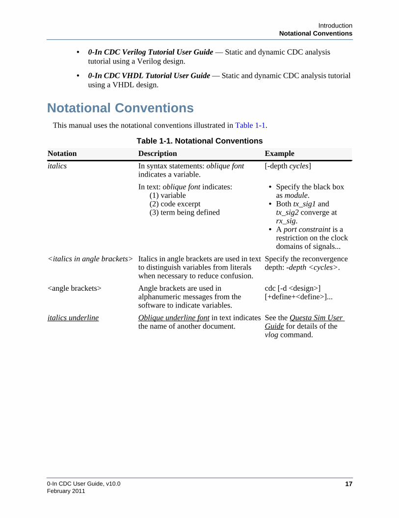
Notational ConventionsThis manual uses the notational conventions illustrated in Table 1-1.
Table 1-1. Notational Conventions
Notation Description Example
italics In syntax statements: oblique fontindicates a variable.
[-depth cycles]
In text: oblique font indicates:(1) variable(2) code excerpt(3) term being defined
• Specify the black boxas module.
• Both tx_sig1 andtx_sig2 converge atrx_sig.
• A port constraint is arestriction on the clockdomains of signals...
<italics in angle brackets> Italics in angle brackets are used in textto distinguish variables from literalswhen necessary to reduce confusion.
Specify the reconvergencedepth: -depth <cycles>.
<angle brackets> Angle brackets are used inalphanumeric messages from thesoftware to indicate variables.
cdc [-d <design>][+define+<define>]...
italics underline Oblique underline font in text indicatesthe name of another document.
See the Questa Sim UserGuide for details of thevlog command.

0-In CDC User Guide, v10.018
IntroductionOnline Help
February 2011
This manual uses the conventions illustrated in Table 1-2 for syntax statements.
The following replaceable variables in directive syntax statements represent the shown objecttypes.
When specifying a directive from a directive syntax statement, substitute for each meta-variablean HDL identifier, or an expression enclosed in parentheses, that evaluates to an object of thecorresponding type.
Online Help0-In software includes several ways of getting online help:
• Shell help
Type -help with any shell command for the syntax of that command. For example:
prompt> vlib -helpUsage: vlib -helpvlib [-short|-dos|-long|-unix] [-archive [-compact <compact>]]
[-unnamed_designs <count>] [{-lock|-unlock} <design>][-locklib|-unlocklib] <library_name>
Table 1-2. Syntax Conventions
Meta-symbol Description Example
. . . Ellipses indicate a repeatable entry. -ports portID. . .
[ ] Square brackets indicate an optionalentry.
[-module module]
{ } Braces indicate a required entry(typically used with |-bars or ellipses).
{-set signal value}...
| Or-bars separate choices in [ ] and { }entries.
[-87|-93|-2002|-2008]
_pattern An argument variable with a _patternsuffix accepts wildcards.
set_constant var_pattern constant
signal Single-bit register or wire.
variable Expression that can change value at any time.
constant Expression that evaluates to a statically constant value.
“string” String enclosed in double-quotes.

IntroductionOnline Help
0-In CDC User Guide, v10.0 19February 2011
• 0in shell help
Type -help with any 0in shell command for the syntax of that command. For example:
prompt> 0in -cmd csl -help. . .usage: compile_search_logicalias: csl -d <design name> [-prefix <prefix for search dut in test bench>] [-ctrl_module <control module name>]...
Verilog Options: [-v95 | -sv | -v2k] [-ctrl <verilog checker control file>]... [-ctrl_list <list of verilog checker control files>...] [+define+<macro[=val]>]... [+incdir+<incdir>]... [+libext+<libext>]... [-cuname <compilation unit name>...]
VHDL Options: [-vhctrl <vhdl checker control file>]... [-93 | -87 | -2002 | -2008]
Assertion Options: [+assert] [-psl] [+propfile+<compile verilog flavor PSL vunit>]... [-pslfile_vl <compile verilog flavor PSL vunit>]... [-pslfile_vh or -pslfile <compile VHDL PSL vunit>]... [-assertion_compiler_stats or -ac_stats] [-ovl] [-ovl_cov] [-qvl] [-sva_strong]
3rd Party Tool Options: [-sim <select simulator (questa,mti,vcs,nc,nc3)>]
Advanced Usage Options: [-G[ ]<<name=value> override top level generic>]... [-g[ ]<<name=value> default top level generic>]... [-use_synthesis_case_directives] [-sif <simulator arg file for running checkers>] [-tcs or -target_cover_statements] [-dut_instance or -di <instance name>...] [-dut_exclude or -de <instance name>...]
RTL Options: [-work <logical work library name>] [-L <search library for saved modules>]... [-Lf <library, searched before ‘uselib>]...
[-modelsimini <modelsim.ini to provide library mapping>]Reporting Options:
[-rcd_file <checker density report file>] [-cr <checker report file>] [-cache <working directory>] [-rel_paths] [-full] [-rcd] [-rcd_level <report level>] [-eode or -exit_on_directive_errors] [+nowarn+<message-id>]...
0-In CDC User Guide, v10.020
IntroductionOnline Help
February 2011
[+error+<message-id>]... [-sir or -static_input_report] [-scr or -static_coverage_report] [-help]Prepares design files for formal verification.
• CW help
The cwhelp 0in shell command displays the syntaxes of the global directives. Forexample:
prompt> 0in -cmd cwhelp set_black_boxusage: set_black_box
<name pattern>...[-dont_use_outputs]
Set module as a black-box for formal processing
Specify cwhelp with no arguments to list the available directives:
prompt> 0in -cmd cwhelp0-In Checker Directive Compilerglobals Global Directivesautocheck_off Turn off autocheckautocheck_on Turn on autocheckautocheck_preference Set autocheck preferenceautocheck_report Set autocheck message and/or waive autocheckcreate_wire Create a checkerware wiredefault_reset Specifies a default resetdisable_assumption Do not use specified checks as formal assumptions
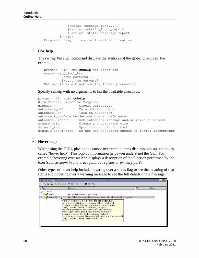
. ..• Hover help
When using the GUIs, placing the cursor over certain items displays pop-up text boxescalled “hover help”. This pop-up information helps you understand the GUI. Forexample, hovering over an icon displays a description of the function performed by theicon (such as zoom in and trace fanin to register or primary port).
Other types of hover help include hovering over a status flag to see the meaning of thatstatus and hovering over a warning message to see the full details of the message.

IntroductionOnline Help
0-In CDC User Guide, v10.0 21February 2011
• InfoHub
The 0-In Functional Verification documentation is available in HTML and PDF formsfrom the 0-In Functional Verification InfoHub. Use a web browser to open the InfoHubtop page:
install_dir/share/doc/info/hubs/index.html

0-In CDC User Guide, v10.022
IntroductionMentor Graphics Support
February 2011
Mentor Graphics SupportMentor Graphics software support includes software enhancements, technical support, access tocomprehensive online services with SupportNet, and the optional On-Site Mentoring service.For details, see:
http://www.mentor.com/supportnet/options
If you have questions about this software release, please log in to SupportNet. You may searchthousands of technical solutions, view documentation, or open a Service Request online at:
http://www.mentor.com/supportnet
If your site is under current support and you do not have a SupportNet login, you may easilyregister for SupportNet by filling out the short form at:
http://www.mentor.com/supportnet/quickaccess/SelfReg.do
All customer support contact information can be found on our web site at:
http://www.mentor.com/supportnet/support_offices.html

0-In CDC User Guide, v10.0 23February 2011
Chapter 2CDC Basics
Most complex designs have more than one clock. Many of these clocks are asynchronous. Forthese designs, the logic clocked by each asynchronous clock forms the clock domain for theclock. Logic entirely inside a clock domain can be verified with the same approach as that for asingle-clock design. However, problems arise from signals that connect logic in different clockdomains. Signals that cross clock domain “boundaries” must be properly synchronized, andthey must obey all relevant transfer protocols. The process of verifying these requirements iscalled clock domain crossing (CDC) analysis.
But, even properly synchronized CDC signals that obey protocol rules do not guarantee validfunctionality. If any CDC signal does not hold steady during the setup and hold time of itsreceiving register, then the register can become metastable—its output can settle at random to avalue that is different from the RTL simulated value.
In effect, data values that cross clock domains can be advanced or delayed randomly relative toRTL simulation. If the receiving logic is not specifically designed to tolerate these metastabilityeffects, then functional errors can occur. Unfortunately, standard simulation cannot accuratelymodel metastability in a design. An extension to standard functional verification is needed tomodel the effects of metastability in a design. The CDC-FX product does just that; CDC-FXruns standard simulation with metastability injected into the circuit.
This chapter describes the method of verifying CDC signals using the CDC compiler andCDC-FX metastability injection. This method combines static CDC analysis, inference ofdesign intent, assertions from an assertion checker library, simulation, and CDC-FXmetastability injection for a complete CDC verification methodology.
Refer to the CDC-FX Metastability Injection Chapter starting on page 159 for additionalinformation.
0-In CDC User Guide, v10.024
CDC BasicsCDC Design Issues
February 2011
CDC Design IssuesCDC verification initially ensures that all appropriate CDC signals have correct synchronizationlogic. But, CDC verification really addresses the larger question:
Does my CDC synchronization logic prevent data corruption across clock domains?
Even for a design that has correct synchronizers on all signals, you must consider questionssuch as:
• What happens if the CDC signals are changing when the handshake signal indicates theyare stable?
• Does the gray-code logic on a multiple bit bus using 2FF synchronization have a bug?
• Does the input to a data synchronizer change in two successive clock cycles of thereceiving domain?
• What happens when multiple CDC signals are recombined and used together in thereceiving domain?
Problems such as these often do not cause simulations to fail; instead, they commonly manifestas intermittent post-silicon failures.
To protect against these types of failures (and ensure CDC problems are addressed early in thedesign process), you can use the CDC verification methodology that consists of a three-prongedapproach as follows:
• Static CDC analysis with the CDC compiler.
• Assertion-based verification with CDC protocol checkers.
• Metastability effects analysis with CDC-FX metastability injected simulation.

CDC BasicsClock Domains
0-In CDC User Guide, v10.0 25February 2011
Clock DomainsA clock domain is a section of a design that has a clock asynchronous to (or which has avariable phase relationship to) another clock in the design. For example, suppose one clock isderived from another clock through a clock divider. These two clocks have a constant phaserelationship; therefore, the two sections of the design that use these clocks are really part of thesame clock domain (Figure 2-1A). However, suppose two clocks have frequencies of 50 MHzand 33 MHz. These clocks’ phase relationships change over time; therefore, they clock twodifferent clock domains (Figure 2-1B).
Figure 2-1. Clock Domains and Clock Dividers
If the primary inputs to a circuit include multiple clocks, then these asynchronous clocksdetermine separate clock domains (Figure 2-2A). If the inputs to a circuit are asynchronous tothe circuit itself, then these asynchronous inputs are in separate clock domains (Figure 2-2B).Clocks are the clock signals of registers and the enable signals of latches (when properlyidentified).
Figure 2-2. Asynchronous Clock Domains
Clock GroupsAll the clocks that are part of the same clock domain constitute a clock group. Hence, clockgroups partition all of the clocks in the design. The clock groups identify the various clockdomains in the design.
clk50clk
Single Clock Domain
clk/2
clock divider
clk
Multiple Clock Domains
clk33
clk50
clk
PLL
clk33clk
A B
clk50
Asynchronous InputsAsynchronous Clocks
clk33
clk50
clk33
clkclk
ab
A B
0-In CDC User Guide, v10.026
CDC BasicsMetastability
February 2011
MetastabilityA clock domain crossing (CDC) signal is a signal originating in a clock domain that crosses theboundary into another domain (whose clock is asynchronous to the original clock) and is thensampled by a register in that asynchronous clock domain.
When the active edge of a CDC signal’s transmit clock is too close to the active edge of thereceive register’s clock, metastability occurs if data changes within the setup/hold time. Withthe TX/RX clock very close, input to the RX register changes within the setup/hold window,which causes metastability. The register’s output settles to an unpredictable value. Metastabilitycan occur if the clocks are asynchronous, or if they are synchronous but have unpredictable ordrifting skews. Every type of bi-stable storage element is susceptible to metastability. Logicsubject to metastability must be designed to “tolerate” its effects.
The effects of metastability are unpredictable in hardware as the output signal can settlerandomly to 1 or 0. However, RTL simulation provides predictable results. As a result, RTLsimulation does not accurately model the hardware implementation when metastability ispresent. To ensure a circuit design is immune to metastability effects, functional verificationmethods must incorporate technology beyond RTL simulation.
To design circuits that tolerate the effects of metastability, you must understand: How registersin hardware exhibit metastability and how registers function in simulation when the conditionsfor metastability are present.
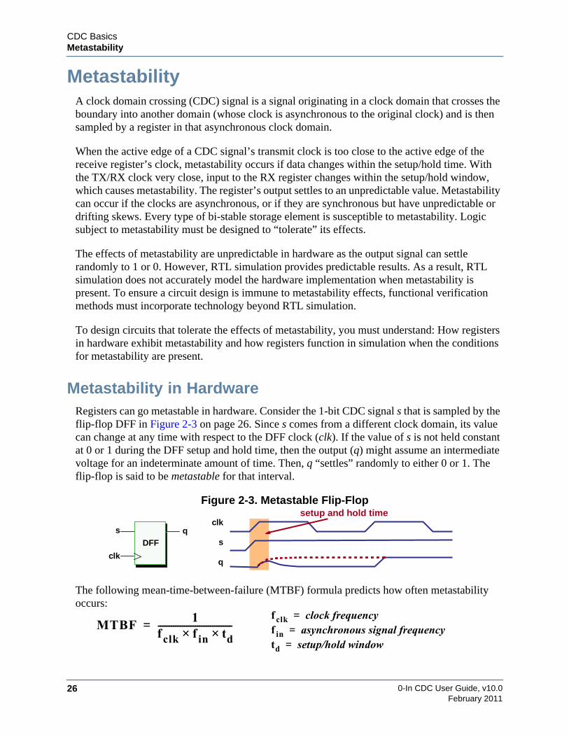
Metastability in HardwareRegisters can go metastable in hardware. Consider the 1-bit CDC signal s that is sampled by theflip-flop DFF in Figure 2-3 on page 26. Since s comes from a different clock domain, its valuecan change at any time with respect to the DFF clock (clk). If the value of s is not held constantat 0 or 1 during the DFF setup and hold time, then the output (q) might assume an intermediatevoltage for an indeterminate amount of time. Then, q “settles” randomly to either 0 or 1. Theflip-flop is said to be metastable for that interval.
Figure 2-3. Metastable Flip-Flop
The following mean-time-between-failure (MTBF) formula predicts how often metastabilityoccurs:
clk
s qclk
s
q
DFF
setup and hold time
MTBF1
fclk f in× td×----------------------------------=f clk clock frequency=f in asynchronous signal frequency=td setup/hold window=

CDC BasicsMetastability
0-In CDC User Guide, v10.0 27February 2011
Metastability in Standard RTL SimulationRegisters cannot go metastable in RTL simulation. RTL simulation handles single-bit registerspredictably as follows:
• If the simulated input switches value before the simulated clock edge, then the simulatedoutput switches value at the clock edge.
• If the simulated input switches value after the simulated clock edge, then the simulatedoutput does not switch value.
Therefore, for both setup time and hold time violations, two results are possible as follows:
• The hardware output value matches the value predicted by simulation.
• The hardware value differs from the value predicted by simulation.
Figure 2-4 shows the resulting four metastability scenarios. Comparing hardware with RTLsimulation behavior: When a setup time violation occurs, the hardware transition is delayedrandomly by one cycle. When a hold time violation occurs, the hardware transition is advancedrandomly by one cycle.
Note that metastability models can be generalized for multibit registers by treating them asaggregate single-bit registers.
Figure 2-4. Four Metastability Scenarios
setup time violationsrx_clk
cdc_s qR
rx_clk
cdc_s
q (hw)
q (sim)
hardwarematchessimulation
hold time violations
rx_clk
cdc_s
q (hw)
q (sim)
Setup time violation where the outputsettles to the simulation value. Thehardware transition is not advanced ordelayed.
Hold time violation where the outputsettles to the simulation value. Thehardware transition is not advanced ordelayed.
hardwarediffers fromsimulation
Setup time violation where the outputsettles to the complement of thesimulation value. The hardwaretransition is delayed by one cycle.
Hold time violation where the outputsettles to the complement of thesimulation value. The hardwaretransition is advanced by one cycle.
rx_clk
cdc_s
q (hw)
q (sim)
rx_clk
cdc_s
q (hw)
q (sim)

0-In CDC User Guide, v10.028
CDC BasicsMetastability
February 2011
Pseudorandom Delay Insertion
A common method of modeling metastability in standard RTL simulation is to introducepseudorandom delays in CDC signals at the synchronizers. For example, Figure 2-5 shows atwo-register synchronizer with a MUX that selects a 3-cycle delayed value (instead of thenormal 2-cycle delayed value) in a pseudorandom manner. End-to-end functional simulationwith these types of pseudorandom delays helps to verify that the design works properly in thepresence of CDC metastability.
Figure 2-5. Synchronizer with Pseudorandom 1-Cycle Delay on Output
However, this method has the following limitations:
• It is incomplete, because it only models two of the four possible metastability scenarios.
• It models metastability only across synchronized CDC signals.
• Results are difficult to predict, because metastability is introduced into the simulation atrandom.
• Synchronization violations are difficult to debug, because the offending metastabilitycan occur any number of cycles before the cycle in which the simulation check first fails(and irrelevant metastability can occur along the way).
Clock Jitter
Another method of modeling CDC metastability effects in standard RTL simulation is to jitterthe clocks in simulation and see if end-to-end functional simulation still works when the clockphase relationships change. This method is good for verifying that the design works properly inthe presence of clock jitter and clock skews. But, this method does not completely model CDCmetastability effects.
clk
q2R1
synchronizer
s q1R3R2
q3
$random()

CDC BasicsMetastability
0-In CDC User Guide, v10.0 29February 2011
CDC-FX Injected RTL SimulationFor metastability injected simulation, circuitry for injecting metastability on a CDC signal ordata bus is inserted between the transmitting register and the first register along the path to thereceiver. For a path without a synchronizer, this is the receiving register itself. For a path with asynchronizer, this is the first register in the synchronizer (Figure 2-6).
Figure 2-6. Metastability Injector for a CDC Data Bus
The ccl compiler generates the checker logic for running metastability injected simulation. Todo this, it adds metastability injection logic for each affected CDC signal or bus in the followingtwo parts:
• CDC clocks monitor logic
Glue logic used to extract load and timing conditions from the circuit.
• cdc_fx checker
Checkers that monitor conditions that might cause metastability on a CDC bus andinjects metastability at the receiver outputs.
The cdc_fx checkers maintain statistics and corner-case counts for the metastability and CDCeffects modeled by the transformed circuit. The cdc_fx checkers have default-off checks(cdc_fx) that fire in cycles in which metastability might occur (for use on data buses that arepresumed to be synchronized properly).
See “CDC-FX Metastability Injection” on page 159 for additional information.
CDC Bus without a Synchronizer
rx_clocktx_clock
tx_reg rx_reg
rx_clocktx_clock
tx_regcdc_fx
checker
metastabilityinjector
rx_reg
clocksmonitor
CDC Bus with a Synchronizer
rx_clocktx_clock
reg
tx_reg rx_reg
synchronizer
rx_clocktx_clock
reg
tx_reg
synchronizer
cdc_fxchecker
rx_reg
clocksmonitor
metastabilityinjector
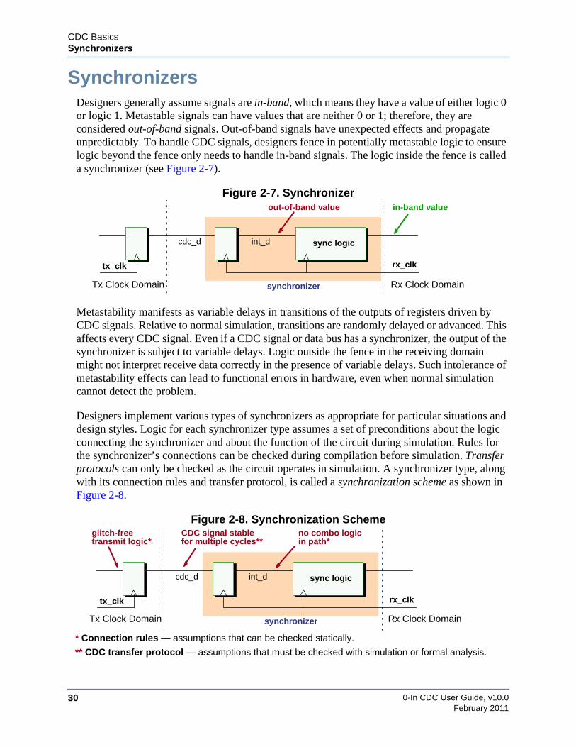
0-In CDC User Guide, v10.030
CDC BasicsSynchronizers
February 2011
SynchronizersDesigners generally assume signals are in-band, which means they have a value of either logic 0or logic 1. Metastable signals can have values that are neither 0 or 1; therefore, they areconsidered out-of-band signals. Out-of-band signals have unexpected effects and propagateunpredictably. To handle CDC signals, designers fence in potentially metastable logic to ensurelogic beyond the fence only needs to handle in-band signals. The logic inside the fence is calleda synchronizer (see Figure 2-7).
Figure 2-7. Synchronizer
Metastability manifests as variable delays in transitions of the outputs of registers driven byCDC signals. Relative to normal simulation, transitions are randomly delayed or advanced. Thisaffects every CDC signal. Even if a CDC signal or data bus has a synchronizer, the output of thesynchronizer is subject to variable delays. Logic outside the fence in the receiving domainmight not interpret receive data correctly in the presence of variable delays. Such intolerance ofmetastability effects can lead to functional errors in hardware, even when normal simulationcannot detect the problem.
Designers implement various types of synchronizers as appropriate for particular situations anddesign styles. Logic for each synchronizer type assumes a set of preconditions about the logicconnecting the synchronizer and about the function of the circuit during simulation. Rules forthe synchronizer’s connections can be checked during compilation before simulation. Transferprotocols can only be checked as the circuit operates in simulation. A synchronizer type, alongwith its connection rules and transfer protocol, is called a synchronization scheme as shown inFigure 2-8.
Figure 2-8. Synchronization Scheme
int_d
Tx Clock Domain Rx Clock Domain
out-of-band value in-band value
synchronizer
sync logiccdc_d
tx_clk rx_clk
* Connection rules — assumptions that can be checked statically.
** CDC transfer protocol — assumptions that must be checked with simulation or formal analysis.
int_d
Tx Clock Domain Rx Clock Domain
no combo logic
synchronizer
sync logiccdc_d
tx_clk rx_clk
glitch-freetransmit logic* in path*
CDC signal stablefor multiple cycles**

CDC BasicsSynchronizers
0-In CDC User Guide, v10.0 31February 2011
Most CDC implementations use one or more synchronizers from a set of popular, well-characterized synchronization schemes. These structured synchronizers must follow well-defined connection rules and should obey specific transfer protocols. CDC identifies clockdomains, CDC signals, and structured synchronizers; and it verifies that the structuredsynchronizers follow their connection rules. Then, CDC promotes their transfer protocols toCheckerWare CDC protocol checkers for use with assertion-based simulation and formalverification.
Any clock domain crossing that does not have a structured synchronizer must be synchronizedby custom logic or software. These ad hoc synchronizers prevent receive registers fromsampling CDC signal values when they are changing. Therefore, the receive register outputs cannever go metastable. For example, an ad hoc synchronizer might use custom logic to control itsreceive register’s load enable signal, or software might control the loading of a circuit’sconfiguration registers.
Control Signal SynchronizersA typical 2DFF 1-bit synchronizer is shown below. In most technologies, if the first register(R1) becomes metastable, it almost always settles to 0/1 before the second register (R2) samplesits output (q1). The 2DFF synchronizer is the most commonly used synchronizer for single-bitCDC connections such as individual control signals. Other structured synchronizers areavailable, such as the 4-latch synchronizer (similar to 2DFF) and the pulse synchronizer (2DFFwith a pulse).
Connection Rules• Logic in cdc_s path must be glitch free• No combinational logic is allowed in
int_s path
CDC Transfer Protocol• Transmit clock domain logic must hold
cdc_s stable for at least the following:
rx_clk
q
2DFF synchronizer
cdc_s int_s
Tx ClockDomain
Rx ClockDomain
R1 R2
periodrx_clk tsetup thold tmax_skew+ + +
rx_clk
cdc_s
int_s
q
rx_clk
cdc_s
int_s
q
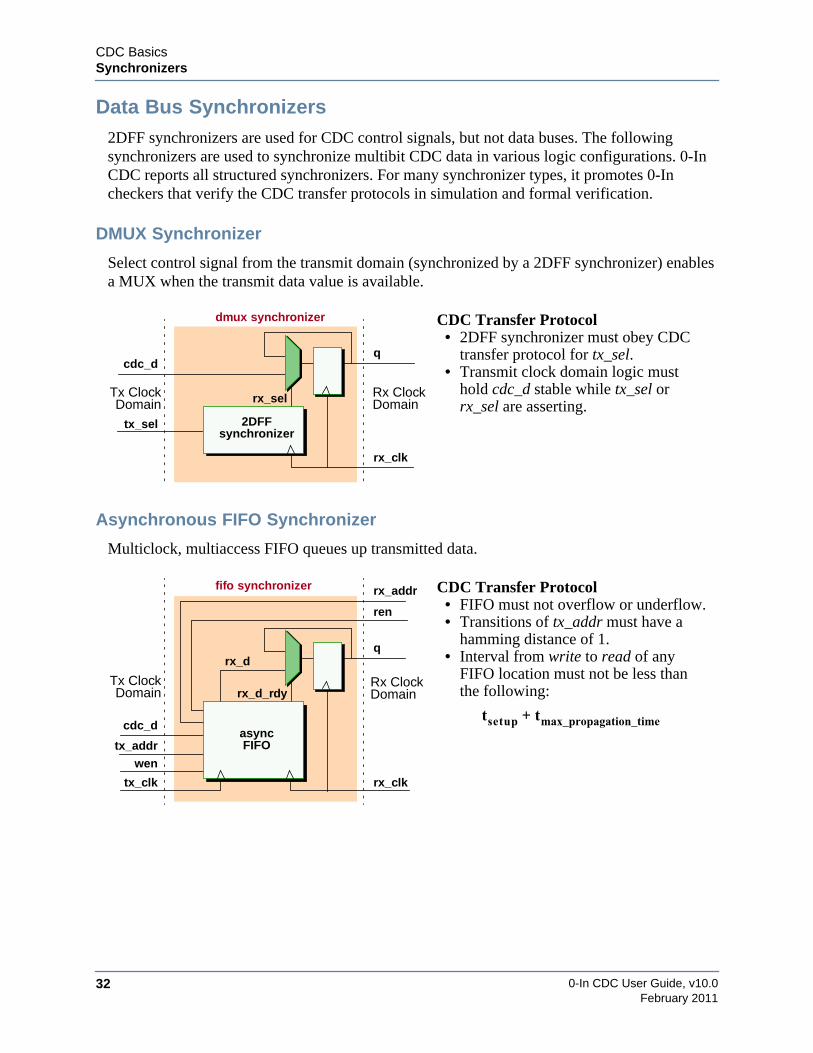
0-In CDC User Guide, v10.032
CDC BasicsSynchronizers
February 2011
Data Bus Synchronizers2DFF synchronizers are used for CDC control signals, but not data buses. The followingsynchronizers are used to synchronize multibit CDC data in various logic configurations. 0-InCDC reports all structured synchronizers. For many synchronizer types, it promotes 0-Incheckers that verify the CDC transfer protocols in simulation and formal verification.
DMUX Synchronizer
Select control signal from the transmit domain (synchronized by a 2DFF synchronizer) enablesa MUX when the transmit data value is available.
Asynchronous FIFO Synchronizer
Multiclock, multiaccess FIFO queues up transmitted data.
CDC Transfer Protocol• 2DFF synchronizer must obey CDC
transfer protocol for tx_sel.• Transmit clock domain logic must
hold cdc_d stable while tx_sel orrx_sel are asserting.
CDC Transfer Protocol• FIFO must not overflow or underflow.• Transitions of tx_addr must have a
hamming distance of 1.• Interval from write to read of any
FIFO location must not be less thanthe following:
rx_clk
q
dmux synchronizer
cdc_d
Tx ClockDomain
Rx ClockDomain
tx_sel
rx_sel
2DFFsynchronizer
rx_clk
q
fifo synchronizer
cdc_d
Tx ClockDomain
Rx ClockDomain
tx_addr
rx_d_rdy
rx_d
wen
tx_clk
ren
rx_addr
asyncFIFO
tsetup tmax_propagation_time+

CDC BasicsSynchronizers
0-In CDC User Guide, v10.0 33February 2011
Multibit Data Synchronizer
2DFF synchronizer synchronizes each bit, but only a single transmit bit at a time should changeduring any receive clock cycle.
Custom Synchronizer
Special-purpose signal or data synchronizer designed, specified, and implemented by the user.
Custom synchronizers can also have clock domain crossings internal to the user-definedmodule.
CDC Transfer Protocol• Transitions of cdc_d must have a
hamming distance of 1.• 2DFF synchronizers must obey the
CDC transfer protocol for each cdc_dbit.
CDC Transfer Protocol• User-defined protocol.
CDC Transfer Protocol• User-defined protocol.
rx_clk
q
multibit synchronizer
cdc_d
2DFFsynchronizer
2DFFsynchronizer
2DFFsynchronizer
d[0]
d[1]
d[2]
Rx
DomainClock
Tx
DomainClock
rx_clk
q
custom synchronizer
cdc_d
Tx ClockDomain
Rx ClockDomain
user-definedmodule
rx_clk
q
custom synchronizer
d
Tx Clock Domain Rx ClockDomain
user-definedmodule
with internal crossing
tx_clk
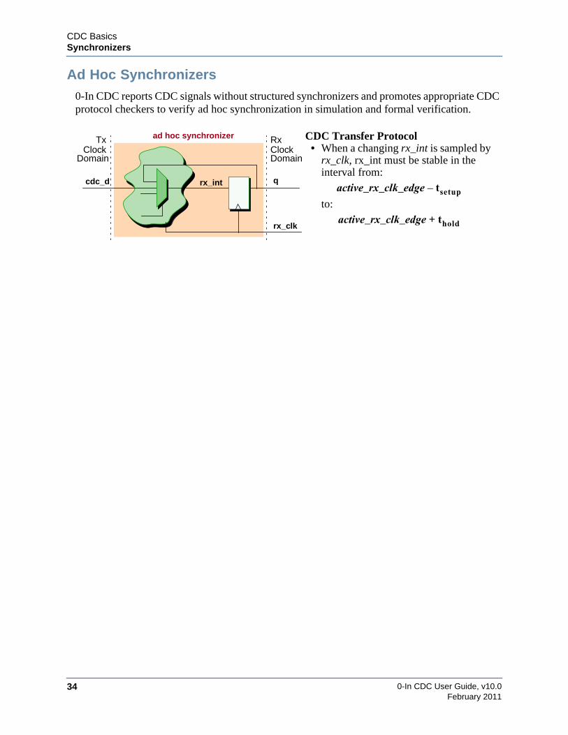
0-In CDC User Guide, v10.034
CDC BasicsSynchronizers
February 2011
Ad Hoc Synchronizers0-In CDC reports CDC signals without structured synchronizers and promotes appropriate CDCprotocol checkers to verify ad hoc synchronization in simulation and formal verification.
CDC Transfer Protocol• When a changing rx_int is sampled by
rx_clk, rx_int must be stable in theinterval from:
to:
rx_clk
q
ad hoc synchronizer
cdc_d
Rx
DomainClock
Tx
DomainClock
rx_int active_rx_clk_edge tsetup–
active_rx_clk_edge thold+

CDC BasicsReconvergence
0-In CDC User Guide, v10.0 35February 2011
ReconvergenceReconvergence is the utilization of separately-propagated correlated information. An exampleof reconvergence is information crossing clock domain boundaries that is recombined in thereceive logic.
The singular problem with reconvergence is:
Can you assure that all of the correlated information used at the destination isconsistent with the information that was transmitted from the source?
CDC signal values might be metastable. Even when proper synchronizers are used, they aresubject to variable delays, which might cause reconverging information to be inconsistent.
Reconvergence occurs in two ways: Local reconvergence — a single item of informationpropagates and is reconstituted in the receive logic, and global reconvergence — multiple itemsof information propagate and are integrated in the receive logic.
An example of local reconvergence is multibit reconvergence of a CDC data bus. Here, a dataunit splits into pieces, crosses a clock domain boundary and then recombines in the receivelogic. In the following example, a reconverged word value is used as the next state of a finitestate machine. The individual bits of the word are synchronized to the receive clock domain, buteach bit is subject to variable delays. As a result, the next_state input to the FSM can represent acommand that is not consistent with the current state.
.
rx_clktx_clk
tx_sig1 rx_sig1
reconverging signals
Tx Clock Domain
tx_sig2 rx_sig2
Rx Clock Domain
rx_clk
next_statecdc_d
synchronizer
synchronizer
synchronizer
d[0]
d[1]
d[2]
Rx
DomainClock
Tx
DomainClock
S1
S4
S2
FSM
?
S3

0-In CDC User Guide, v10.036
CDC BasicsReconvergence
February 2011
Another example of local reconvergence is multicycle reconvergence of a CDC signal thatcontains sequential information transmitted to receive logic. Here, variable delays in thepropagated signal can disturb correlations between consecutive transitions. In the followingexample, the cdc_s pulse is not propagated to the receive logic. To avoid problems withmulticycle reconvergence, either the transmit logic must not transition data too quickly or thereceive logic must tolerate the loss of information in consecutive cycles.
An example of global reconvergence is a set of data items transmitted across a clock domainboundary through different synchronizers that are combined in the receive clock domain.Another example of global reconvergence is the transmission of multiple items of informationacross a clock domain boundary at different times using the same synchronizer.
Global and local reconvergence problems in CDC circuits are avoided by using propersynchronizers and good reconvergence schemes. A good implementation ensures information isalways consistent. Either variable delay data cannot be sampled in the receive domain or thereceive domain logic can recover from variable delayed values. In the following example of agood scheme, an arbiter selects a receive data value when the corresponding asynchronousFIFO read data value is guaranteed to be ready.
A bad implementation results in unrecoverable errors in simulation or in the hardwareimplementation. In the following example of a bad scheme, variable delays can cause the wrongcommand to be applied to the data.
rx_clk
qcdc_s int_s
Tx ClockDomain
Rx ClockDomain
R1 R2
rx_clkcdc_sint_s
q
rx_clk
async FIFO
async FIFO
DomainRx Clock
DomainTx Clock
synchronizer
synchronizer
arbiter
tx_0
rx_0
tx_1
rx_1
rx_rdy
rx_out
selrdy_0
rdy_1
rx_clk
async FIFO
async FIFO
DomainRx Clock
DomainTx Clock
synchronizer
synchronizer
tx_cmd rx_cmd
tx_data rx_data
applycommand
to data

CDC BasicsReconvergence
0-In CDC User Guide, v10.0 37February 2011
Knowing which paths are reconvergent CDC paths is important for assessing reconvergenceissues. But for many multiple-clock architectures, the number of reconvergent CDC paths canbe staggering. To help rank paths for assessment, reconvergent paths can be filtered by severalcharacteristics.
The reconvergence depth of a group of reconvergent CDC paths is the sequential depth from thesynchronizers to the reconvergence point. Sometimes, heuristic information about thefunctional characteristics of the circuit can specify a reconvergence depth limit for problems tooccur.
General reconvergent CDC paths can start anywhere in the transmit domain. Reconvergentpaths that start at different points can have reconvergence problems. However, single-sourcereconvergence paths—those reconvergent paths that start from the same transmit domainsource—are characteristically vulnerable to reconvergence issues. Analogous to generalreconvergent CDC paths, each group of single-source reconvergence paths has a sequentialdistance (called the divergence depth) from the single source to the synchronizers.
Tx Clock Domain RX Clock Domain
synchronizer
synchronizer
synchronizer
single-source reconvergence paths
reconvergence depthdivergence depth

0-In CDC User Guide, v10.038
CDC BasicsReconvergence
February 2011
Verifying ReconvergenceSimulation alone is not sufficient to verify that a circuit’s hardware implementation toleratesmetastability effects and will operate correctly without reconvergence issues. Normalsimulation does not model metastability robustly and completely misses behavior that canmanifest in the circuit’s hardware implementation. A multi-faceted approach to CDCverification is necessary for a high degree of confidence that a particular reconvergence schemeis a good one.
• Static reconvergence analysis.
0-In CDC creates static reconvergence reports showing general and single-sourcereconvergence points organized by signature. These reports can uncover reconvergencescenarios that might be overlooked.
• CDC transfer protocol checking.
0-In CDC identifies structured synchronizers and promotes their CDC transfer protocolsto CDC assertion checkers for use in simulation and formal verification.
• Metastability injected verification.
CDC-FX identifies registers that can become metastable. For each such register, 0-InCDC generates a cdc_fx checker directive for metastability injected simulation. Thischecker includes metastability injection and analysis logic.
During simulation, the cdc_fx checker assumes control of the register’s output. It injectsvariable delays on bits that transition when transmit and receive clocks are almostaligned. This causes some outputs to mimic metastable behavior in simulation.Problems are detected by end-to-end test failures. If the verification environment isinstrumented with assertions, problems also can be detected by assertion failures.

CDC BasicsCDC Schemes
0-In CDC User Guide, v10.0 39February 2011
CDC SchemesThe CDC compiler analyzes the design netlist and identifies logic involving CDC signals thatmatches various pattern templates. Each occurrence of logic that matches a template is called aCDC scheme. For example, you might have a 1-bit CDC signal sig from clock domain A beingsynchronized by two in-phase D flip-flops in clock domain B. The CDC compiler identifies thisparticular clock domain crossing and its synchronization logic.
Classes of CDC schemes with the same functionality are called CDC scheme types (todistinguish them from individual CDC schemes). For example, the above CDC path with itssynchronization logic is a CDC scheme of the “two_dff” type.
CDC Schemes starting on page 179 have the detailed data sheets for the CDC schemes.
Attributes of CDC SchemesEach CDC scheme detected by the CDC compiler has two attributes: severity and promotion(see page 39). By default, the severity and promotion attributes are taken from the defaultattributes of the CDC scheme type. You can adjust these attributes for individual CDC schemes,groups of schemes, and for the entire set of CDC schemes of a particular scheme type, using theset_cdc_report global directive (page 293).
Part of the initial CDC compiler run is typically spent adjusting the attributes of CDC schemesto fine-tune the CDC reporting for the target design characteristics. For example, a“combo_logic” scheme in one part of the design might be acceptable, but it might be a seriousconcern in another part of the design.
SeveritySeverity is an indicator of the seriousness of the particular logic pattern (CDC scheme). It alsoreflects the action you are expected to take. The severity levels are:
• Violation
A violation is considered a must-fix problem. For example, an unsynchronized CDCsignal from clock domain A to clock domain B might be a concern, so you might want toassign severity violations to all of these CDC schemes.
• Caution
A caution is considered a valid static scheme, but it has an associated CDC transferprotocol that should be verified in simulation or by formal verification. Most cautionshave designated CDC protocol checkers that the CDC compiler configuresautomatically and “promotes” for assertion-based verification.

0-In CDC User Guide, v10.040
CDC BasicsCDC Schemes
February 2011
• Evaluation
An evaluation is a valid CDC scheme that uses an appropriate synchronizer. Thescheme’s CDC protocol must still be checked.
• Proven
A proven scheme is a valid CDC scheme with an associated CDC transfer protocol thatformal CDC analysis has proven cannot be violated. No CDC protocol checkers for thescheme are “promoted” for assertion-based verification.
• Waived
A waived scheme is a CDC scheme with a CDC transfer protocol that does not requireverification. CDC data for waived schemes are included in the 0in_cdc database, but noCDC protocol checkers for the scheme are “promoted” for assertion-based verification.
• Filtered (Reporting Off)
A filtered scheme is a CDC scheme that does not need CDC analysis. For example,test/configuration logic has a combo_logic scheme, but the combinational logic isconstant during regular operation. Here, you can filter this combo_logic scheme so it isnot reported (unless set_cdc_preference -filtered_report is specified).
PromotionWhenever possible, CDC creates and configures a CDC transfer protocol checker for a scheme.Most synchronizers have corresponding protocol checkers. The process of identifying a CDCscheme and creating its protocol checker is called checker promotion. Here, a CDC scheme isdeemed OK from a static perspective. The compiler does not have enough information todetermine whether or not a synchronization problem will occur. The answer depends on theoperating environment of the design.
Promoted checkers can be used during simulation to monitor CDC activity and verify propersynchronization of CDC signals. They are also used in static and dynamic formal verification.
Use the set_cdc_report global directive (see page 293) to turn off CDC checker promotion forspecific CDC schemes.
Signals in Unnamed Blocks
By default, CDC protocol checker (and FX checker) promotion is disabled for signals inside IF-generate blocks (the current Questa implementation does not allow access to these blocknames). But if the specified simulator is VCS (i.e. 0in -sim vcs -cmd cdc...), these checkers arepromoted. However, checkers with signals in regular RTL unnamed blocks are not promoted. Ifthe specified simulator is NC (i.e. 0in -sim nc -cmd cdc...), checkers with signals in implicitgenerate blocks are not promoted.

CDC BasicsCDC Schemes
0-In CDC User Guide, v10.0 41February 2011
CDC Synchronization SchemesMost CDC scheme types refer to synchronization logic. Some schemes apply to single-bit CDCsignal synchronization, some apply to multiple-bit data bus synchronization, and some apply toboth.
SignalsSignal synchronization schemes identify single-bit CDC signals with various synchronizers. Forexample, a two_dff scheme uses two in-phase D flip-flops clocked in the receive domain as asynchronizer.
Table 2-1 shows the signal synchronization scheme types.
Table 2-1. Signal Synchronization Scheme
Scheme Synchronizer MessageDefaultSeverity
async_reset Asynchronous resetscheme.
ASYNC RESET evaluation
async_reset_no_sync —none— ASYNC RESET NOSYNC
violation
dff_sync_gated_clk Two flip-flops with gatedclock.
DFF GATED SYNC caution
four_latch Three or more cascadedlatches.
FOUR LATCHSYNCHRONIZER
evaluation
no_sync —none— MISSINGSYNCHRONIZER
violation
pulse_sync Pulse. PULSE SYNC evaluation
shift_reg Shift register. SHIFT REG evaluation
two_dff Two or more in-phase flip-flops.
TWO DFFSYNCHRONIZER
evaluation
two_dff_phase Two out-of-phase flip-flops.
TWO DFFSYNCHRONIZEROPPOSITE POLARITY
caution
custom_sync Custom. CUSTOM evaluationorviolation
rx_clk
rx_sigtx_sig
Tx Clock Domain
DFF DFFDFF
tx_clk
Rx Clock Domain
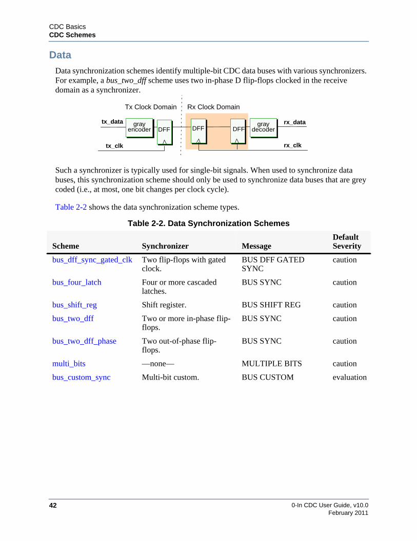
0-In CDC User Guide, v10.042
CDC BasicsCDC Schemes
February 2011
DataData synchronization schemes identify multiple-bit CDC data buses with various synchronizers.For example, a bus_two_dff scheme uses two in-phase D flip-flops clocked in the receivedomain as a synchronizer.
Such a synchronizer is typically used for single-bit signals. When used to synchronize databuses, this synchronization scheme should only be used to synchronize data buses that are greycoded (i.e., at most, one bit changes per clock cycle).
Table 2-2 shows the data synchronization scheme types.
Table 2-2. Data Synchronization Schemes
Scheme Synchronizer MessageDefaultSeverity
bus_dff_sync_gated_clk Two flip-flops with gatedclock.
BUS DFF GATEDSYNC
caution
bus_four_latch Four or more cascadedlatches.
BUS SYNC caution
bus_shift_reg Shift register. BUS SHIFT REG caution
bus_two_dff Two or more in-phase flip-flops.
BUS SYNC caution
bus_two_dff_phase Two out-of-phase flip-flops.
BUS SYNC caution
multi_bits —none— MULTIPLE BITS caution
bus_custom_sync Multi-bit custom. BUS CUSTOM evaluation
rx_clk
rx_datatx_data
Tx Clock Domain
DFF DFFDFF
tx_clk
Rx Clock Domain
grayencoder
graydecoder
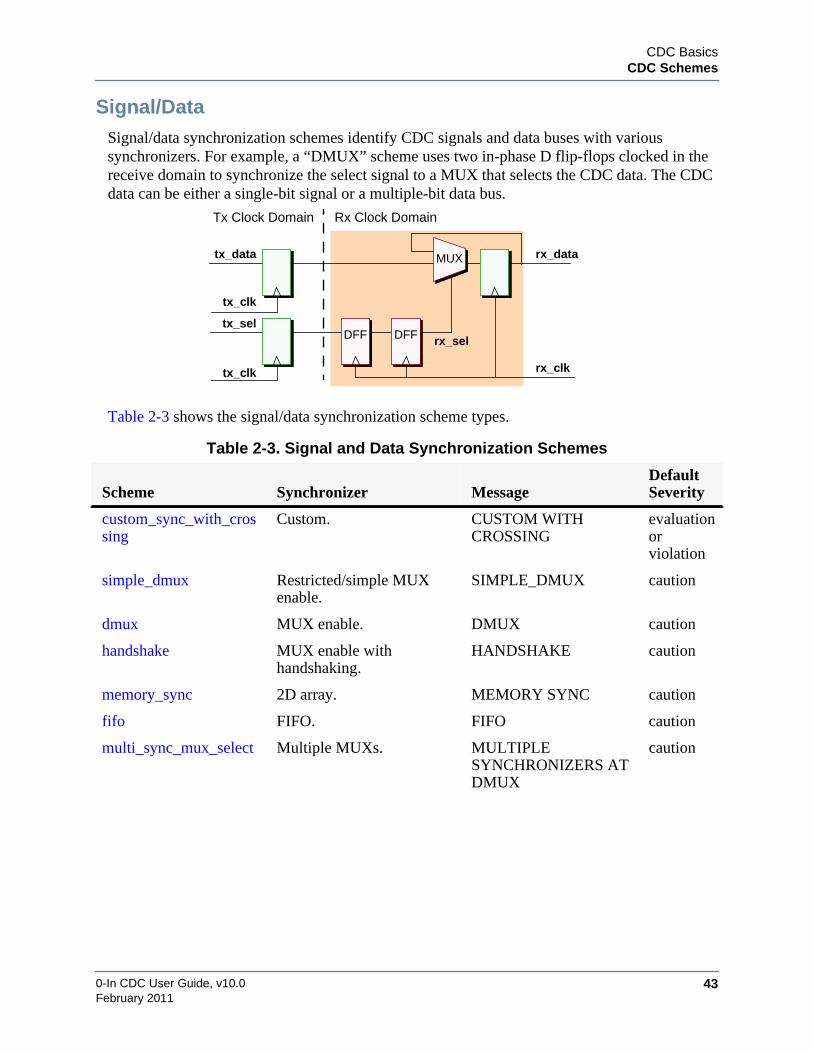
CDC BasicsCDC Schemes
0-In CDC User Guide, v10.0 43February 2011
Signal/DataSignal/data synchronization schemes identify CDC signals and data buses with varioussynchronizers. For example, a “DMUX” scheme uses two in-phase D flip-flops clocked in thereceive domain to synchronize the select signal to a MUX that selects the CDC data. The CDCdata can be either a single-bit signal or a multiple-bit data bus.
Table 2-3 shows the signal/data synchronization scheme types.
Table 2-3. Signal and Data Synchronization Schemes
Scheme Synchronizer MessageDefaultSeverity
custom_sync_with_crossing
Custom. CUSTOM WITHCROSSING
evaluationorviolation
simple_dmux Restricted/simple MUXenable.
SIMPLE_DMUX caution
dmux MUX enable. DMUX caution
handshake MUX enable withhandshaking.
HANDSHAKE caution
memory_sync 2D array. MEMORY SYNC caution
fifo FIFO. FIFO caution
multi_sync_mux_select Multiple MUXs. MULTIPLESYNCHRONIZERS ATDMUX
caution
tx_clk
tx_data rx_data
rx_clktx_clk
tx_selrx_selDFFDFF
MUX
Tx Clock Domain Rx Clock Domain

0-In CDC User Guide, v10.044
CDC BasicsCDC Schemes
February 2011
Schemes with Potential CDC ProblemsIn addition to identifying CDC synchronization schemes, the CDC compiler identifies CDCschemes that exhibit the potential for error. For example, combinational logic in a CDC pathcould cause a valid synchronizer to malfunction.
Table 2-4 shows the potential CDC problem scheme types.
Table 2-4. Potential CDC Problem Schemes
Scheme Problem MessageDefaultSeverity
blackbox Black box in fan-out of asynchronized signal.
BLACKBOX caution
combo_logic Combinational logic on asynchronization path.
COMBO LOGIC violation
fanin_different_clks Fan-in logic frommultiple clock domains.
FANIN LOGICFROM DIFFERENTCLOCKS
violation
reconvergence Reconvergent CDCsignals.
RECONVERGENCE violation
single_source_reconvergence Reconvergent CDCsignals from a singlesource.
SSR violation
redundant CDC signal drivesmultiple synchronizers.
REDUNDANT violation
port_constraint_mismatch Custom synchronizersconnected in series.
SERIESREDUNDANT
violation
series_redundant Custom synchronizersconnected in series.
SERIESREDUNDANT
caution
rx_clk
Tx Clock Domain Rx Clock Domain
tx_clk
tx_data rx_datasynchronizer
combinational logic

CDC BasicsStatic CDC Analysis
0-In CDC User Guide, v10.0 45February 2011
Static CDC AnalysisStatic CDC analysis performs the following critical functions for CDC verification:
1. Verifies synchronizers.
Static CDC analysis examines the design RTL and uses the user-specified and inferredclock groups to find the clock trees that determine the clock domains in the design. Itthen assigns each register to a clock domain. Static CDC analysis identifies the CDCsignals by finding registers that drive registers from other clock domains and verifyingthat correct synchronizers are present on all CDC signals.
2. Identifies CDC schemes.
Static CDC analysis categorizes each CDC logic pattern as one of a set of predefinedCDC schemes. For example, one scheme contains all single-bit CDC signals that aresynchronized by two-register data synchronizers. Another scheme contains all multiple-bit CDC signals that are not synchronized. Some schemes are identified as violations.For example, the following figure shows single-bit CDC signals with combinationallogic driving, or within, the synchronizers.
You can redefine the statuses used for the different schemes. For example, you canmake latch synchronization a violation.
3. Verifies certain CDC protocols
If CDC formal verification is enabled, static CDC analysis includes static formalanalysis of certain CDC protocols.
4. Promotes CDC protocol checkers.
Static CDC analysis generates CDC protocol checkers for certain CDC schemes basedon their scheme type, transmit clock, transmit signals, receive clock and receive signals.
rx_clk
rx_sigtx_sig
Tx Clock Domain
DFF DFFDFF
tx_clk
Rx Clock Domain
combinational logicbetween DFFs
rx_clk
rx_sigtx_sig
Tx Clock Domain
DFF DFFDFF
tx_clk
Rx Clock Domain
combinational logicdrives input to synchronizer
0-In CDC User Guide, v10.046
CDC BasicsStatic CDC Analysis
February 2011
CDC checkers are not promoted for CDC schemes that have severity proven, evaluation,waived or filtered. Promoted checkers represent CDC protocols that need assertion-based analysis by the 0-In formal tools and possibly simulation.
Formal CDCFormal CDC is an advanced option of static CDC analysis that tries to verify the CDC transferprotocols of certain CDC schemes using a built-in formal proof engine. Formal CDC analyzesthe fanin logic of these CDC schemes. If formal CDC finds a proof that a CDC scheme’sprotocol cannot be violated, that scheme is reported as a proven scheme. Since the scheme’ssynchronization is valid, no protocol checker is promoted for the scheme. If CDC formalanalysis cannot find a proof that the protocol cannot be violated, the result is inconclusive. So,the associated protocol checker is promoted for verification by the 0-In formal tools or bysimulation. The proportion of time formal CDC spends analyzing protocols is controlled by theformal CDC effort level:
low —> medium —> high —> maximum
The default formal CDC effort level is low. Running static CDC with a higher formal effortlevel can result in additional proven CDC schemes. The formal CDC engine is tuned to analyzetwo specific types of CDC protocols: signal stability protocols and gray-coding protocols.
Signal Stability Protocols
Single-bit CDC signals can be synchronized by various different types of synchronizers.However, such synchronization must follow a signal stability protocol where each new value ofa transmit signal is held stable long enough for the receiving domain to sample it at least twice.Formal CDC tries to find proofs for the signal stability protocols by analyzing the transmitsignal pulse widths of the following types of CDC schemes:
• dff_sync_gated_clk
• four_latch
• pulse_sync
• shift_reg
• two_dff
• two_dff_phase
CDC BasicsStatic CDC Analysis
0-In CDC User Guide, v10.0 47February 2011
Gray-Coding Protocols
Multibit CDC signals (i.e., data buses) can be synchronized by synchronizers typically used forsingle-bit signals. However, such synchronization must follow a gray-coding protocol whereonly one data bit changes at a time. Formal CDC tries to find proofs for the gray-codingprotocols of the following types of CDC schemes:
• bus_dff_sync_gated_clk
• bus_four_latch
• bus_shift_reg
• bus_two_dff
• bus_two_dff_phase
• reconvergence (if enabled by set_cdc_preference -promote_reconvergence).
CDC Protocol Checker PromotionAssertions are specifications of design behavior. They can be checked during simulation withassertions and they can act as targets and constraints for formal verification. The CDC transferprotocol for a CDC synchronization scheme is an assertion. For example, consider a CDCsignal synchronized by a two-register data synchronizer. This synchronization scheme has thefollowing implied CDC protocol:
• The transmit signal remains stable until the synchronizer’s output register has sampledthe previous value.
This protocol can be checked with the following assertion using simulation with assertions andformal verification:
• The transmit signal must not change for at least N consecutive transmit-clock cycles,where N is a function of the transmit-clock and receive-clock frequencies.
If this assertion is violated, then a possible counterexample exists in which metastability on theCDC signal can cause an incorrect result. In this case, the transmitted data is missed by thereceiver logic. In regular simulation (which is not subject to metastability unless it is acatastrophic violation of the protocol), the signal reaches its goal and the problem is notdetected. However, when using simulation with assertions, an assertion fires. You can thenexamine the conditions under which the failure occurs and correct the design problem.
Specifying Design Intent
A checker is a conglomeration of assertions and a CDC protocol checker is a special type ofchecker configured to verify the CDC transfer protocol for a CDC synchronization scheme. ACDC protocol checker’s assertions completely characterize its associated synchronization
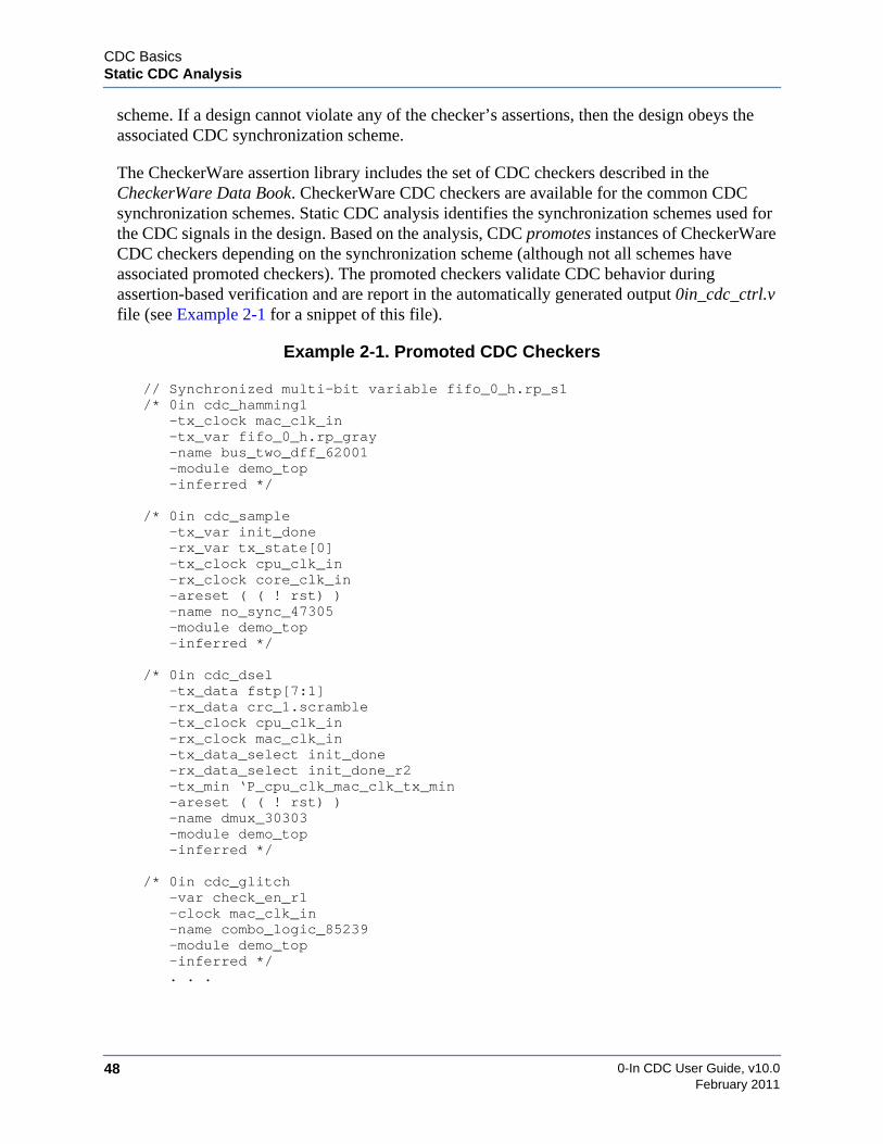
0-In CDC User Guide, v10.048
CDC BasicsStatic CDC Analysis
February 2011
scheme. If a design cannot violate any of the checker’s assertions, then the design obeys theassociated CDC synchronization scheme.
The CheckerWare assertion library includes the set of CDC checkers described in theCheckerWare Data Book. CheckerWare CDC checkers are available for the common CDCsynchronization schemes. Static CDC analysis identifies the synchronization schemes used forthe CDC signals in the design. Based on the analysis, CDC promotes instances of CheckerWareCDC checkers depending on the synchronization scheme (although not all schemes haveassociated promoted checkers). The promoted checkers validate CDC behavior duringassertion-based verification and are report in the automatically generated output 0in_cdc_ctrl.vfile (see Example 2-1 for a snippet of this file).
Example 2-1. Promoted CDC Checkers
// Synchronized multi-bit variable fifo_0_h.rp_s1/* 0in cdc_hamming1
-tx_clock mac_clk_in-tx_var fifo_0_h.rp_gray-name bus_two_dff_62001-module demo_top-inferred */
/* 0in cdc_sample-tx_var init_done-rx_var tx_state[0]-tx_clock cpu_clk_in-rx_clock core_clk_in-areset ( ( ! rst) )-name no_sync_47305-module demo_top-inferred */
/* 0in cdc_dsel-tx_data fstp[7:1]-rx_data crc_1.scramble-tx_clock cpu_clk_in-rx_clock mac_clk_in-tx_data_select init_done-rx_data_select init_done_r2-tx_min ‘P_cpu_clk_mac_clk_tx_min-areset ( ( ! rst) )-name dmux_30303-module demo_top-inferred */
/* 0in cdc_glitch-var check_en_r1-clock mac_clk_in-name combo_logic_85239-module demo_top-inferred */. . .
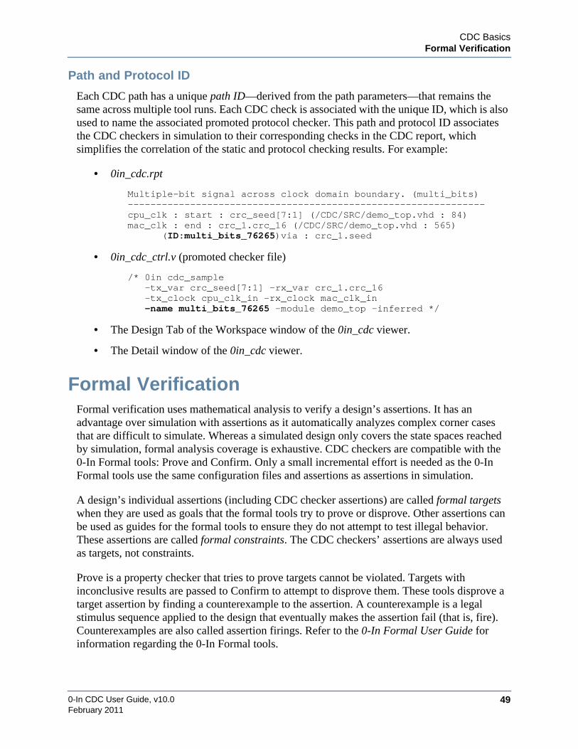
CDC BasicsFormal Verification
0-In CDC User Guide, v10.0 49February 2011
Path and Protocol ID
Each CDC path has a unique path ID—derived from the path parameters—that remains thesame across multiple tool runs. Each CDC check is associated with the unique ID, which is alsoused to name the associated promoted protocol checker. This path and protocol ID associatesthe CDC checkers in simulation to their corresponding checks in the CDC report, whichsimplifies the correlation of the static and protocol checking results. For example:
• 0in_cdc.rpt
Multiple-bit signal across clock domain boundary. (multi_bits)---------------------------------------------------------------cpu_clk : start : crc_seed[7:1] (/CDC/SRC/demo_top.vhd : 84)mac_clk : end : crc_1.crc_16 (/CDC/SRC/demo_top.vhd : 565)
(ID:multi_bits_76265)via : crc_1.seed
• 0in_cdc_ctrl.v (promoted checker file)
/* 0in cdc_sample-tx_var crc_seed[7:1] -rx_var crc_1.crc_16-tx_clock cpu_clk_in -rx_clock mac_clk_in-name multi_bits_76265 -module demo_top -inferred */
• The Design Tab of the Workspace window of the 0in_cdc viewer.
• The Detail window of the 0in_cdc viewer.
Formal VerificationFormal verification uses mathematical analysis to verify a design’s assertions. It has anadvantage over simulation with assertions as it automatically analyzes complex corner casesthat are difficult to simulate. Whereas a simulated design only covers the state spaces reachedby simulation, formal analysis coverage is exhaustive. CDC checkers are compatible with the0-In Formal tools: Prove and Confirm. Only a small incremental effort is needed as the 0-InFormal tools use the same configuration files and assertions as assertions in simulation.
A design’s individual assertions (including CDC checker assertions) are called formal targetswhen they are used as goals that the formal tools try to prove or disprove. Other assertions canbe used as guides for the formal tools to ensure they do not attempt to test illegal behavior.These assertions are called formal constraints. The CDC checkers’ assertions are always usedas targets, not constraints.
Prove is a property checker that tries to prove targets cannot be violated. Targets withinconclusive results are passed to Confirm to attempt to disprove them. These tools disprove atarget assertion by finding a counterexample to the assertion. A counterexample is a legalstimulus sequence applied to the design that eventually makes the assertion fail (that is, fire).Counterexamples are also called assertion firings. Refer to the 0-In Formal User Guide forinformation regarding the 0-In Formal tools.
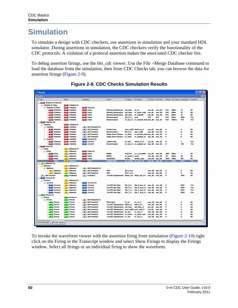
0-In CDC User Guide, v10.050
CDC BasicsSimulation
February 2011
SimulationTo simulate a design with CDC checkers, use assertions in simulation and your standard HDLsimulator. During assertions in simulation, the CDC checkers verify the functionality of theCDC protocols. A violation of a protocol assertion makes the associated CDC checker fire.
To debug assertion firings, use the 0in_cdc viewer. Use the File >Merge Database command toload the database from the simulation, then from CDC Checks tab, you can browse the data forassertion firings (Figure 2-9).
Figure 2-9. CDC Checks Simulation Results
To invoke the waveform viewer with the assertion firing from simulation (Figure 2-10) rightclick on the Firing in the Transcript window and select Show Firings to display the Firingswindow. Select all firings or an individual firing to show the waveform.
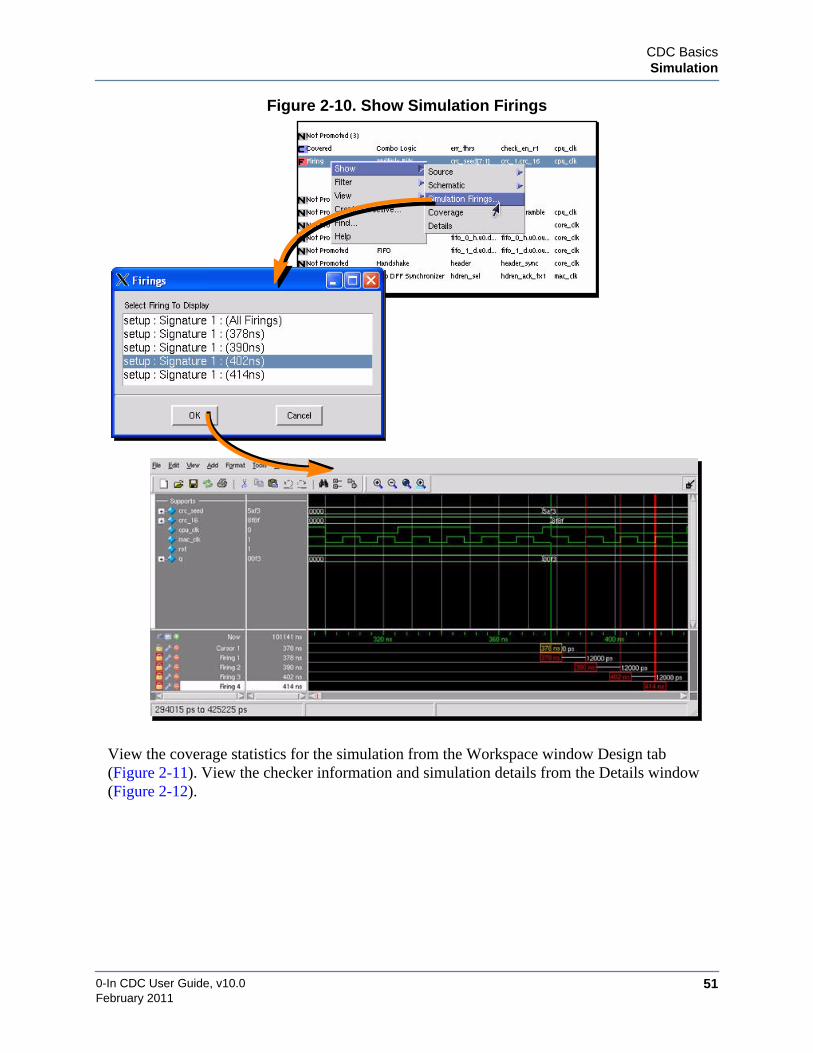
CDC BasicsSimulation
0-In CDC User Guide, v10.0 51February 2011
Figure 2-10. Show Simulation Firings
View the coverage statistics for the simulation from the Workspace window Design tab(Figure 2-11). View the checker information and simulation details from the Details window(Figure 2-12).

0-In CDC User Guide, v10.052
CDC BasicsSimulation
February 2011
Figure 2-11. Simulation Coverage
Figure 2-12. Checker Simulation Details

CDC BasicsStatus Flags
0-In CDC User Guide, v10.0 53February 2011
Status FlagsStatus flags give you a quick assessment of the results of CDC verification from the CDC GUI.The flags help you determine which CDC issues to examine first and they highlight additionalproblems you should investigate. Figure 2-13 shows a region of a CDC checks tab in the resultspane of the CDC GUI after a CDC verification session, formal verification and simulation withthe promoted CDC checkers. Entries can have Static status, Prove status and Simulation statusas described in Table 2-5.
Figure 2-13. CDC Checks Status Flags
Table 2-5. CDC Checks Status Flags
Flag Description Static Prove Sim
Violation and FiringCDC scheme’s severity level is violation and its protocol isviolated in simulation.
ViolationCDC scheme’s severity level is violation.
FiringCDC scheme’s protocol is violated in simulation.
ProvenCDC scheme’s protocol cannot be violated.
EvaluationCDC scheme’s severity level is evaluation.
status flagsin CDC
Checks tab
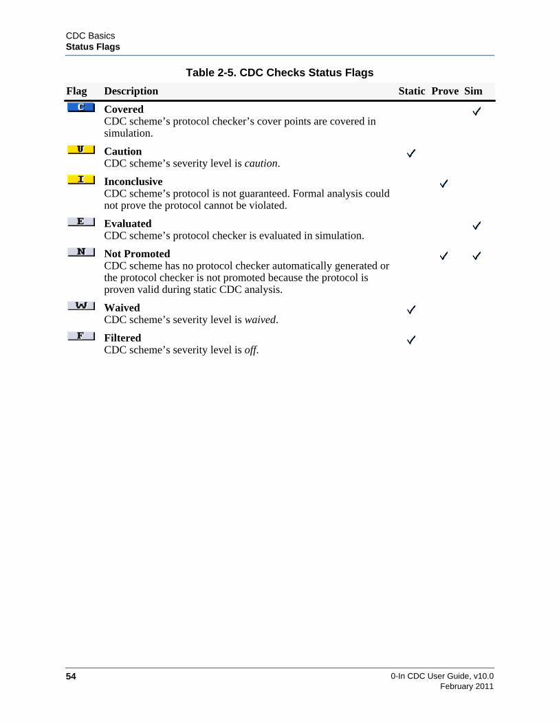
0-In CDC User Guide, v10.054
CDC BasicsStatus Flags
February 2011
CoveredCDC scheme’s protocol checker’s cover points are covered insimulation.
CautionCDC scheme’s severity level is caution.
InconclusiveCDC scheme’s protocol is not guaranteed. Formal analysis couldnot prove the protocol cannot be violated.
EvaluatedCDC scheme’s protocol checker is evaluated in simulation.
Not PromotedCDC scheme has no protocol checker automatically generated orthe protocol checker is not promoted because the protocol isproven valid during static CDC analysis.
WaivedCDC scheme’s severity level is waived.
FilteredCDC scheme’s severity level is off.
Table 2-5. CDC Checks Status Flags
Flag Description Static Prove Sim

0-In CDC User Guide, v10.0 55February 2011
Chapter 3Compilation
CDC analysis runs on a compiled image of the design logic plus a clock domain model. A set ofdesign compilation utilities is used to compile the design logic from source files. Then, the CDCanalyzer (cdc) is used to create a clock domain model. If this compilation completes withouterror, cdc performs CDC analysis and generates data for the CDC GUI. Two methods can beused to compile the design and clock domain model, and then perform CDC analysis:
• 1-Step Compilation
Instead of running the design compilation utilities separately from the cdc command,add the arguments for design compilation to the cdc invocation. The design is compiledfirst (using the design compilation utilities “under-the-hood”). Then, the clock domainmodel is created and CDC analysis is performed—all in one step using the cdccommand. This method only works for restricted Verilog designs.
• 2-Step Compilation
Use the design compilation utilities to create and maintain a compiled design library.Use the cdc command to compile the clock domain model and run CDC analysis.
Figure 3-1. CDC Compilation Methods
0in -cmd cdc
designfiles
control
design libraries
2-Step Compilation
Questa Compilersand Library
Management Tools
Compile design libraries
Compile clock domain
files
0in -cmd cdc
Verilog
files
control
design libraries
1-Step Compilation
Questa Compilersand Library
Management Tools
clock domain
Compile design libraries
files
and clock domain model
design
model
modelclock domain
model

0-In CDC User Guide, v10.056
Compilation1-Step Compilation
February 2011
1-Step CompilationFor the compilation of Verilog-only designs (but not SystemVerilog) you can use the 1-stepcompilation method. To do this, add the 1-step compilation arguments (Table 3-1) to the cdcinvocation. The cdc compiler uses the design compilation utilities “under-the-hood” to compilethe design and stores the compiled design library in the 0in cache. For example:
cdc -d dut -ctrl ctrl.v -f design.f +define+mode=initialized -y ../mylib
See “cdc: Clock Domain Crossing Analyzer” on page 64 for a description of the cdc commandand clock domain model compilation.
Table 3-1. 1-Step Compilation Options
{Verilog_file | –f filelist}… [-v95] [+define{+macro[=value}…][+incdir{+include_dir}…] [+libext{+extension}…] [–y library_dir]… [–v library_file]…[–skip_protected_modules] [–skip_protected_code] [–ignore_translate_off][–ignore_synthesis_off] [–modelsimini init_file]
Verilog_file… Verilog source files.–f filelist File containing additional Verilog design files and arguments–v95 Verilog version is Verilog 95. Default: Verilog 2K.+define{+macro[=value]} Text macro specification.+incdir+dir Include directory.+libext{+extension}… File extensions to use when searching for library files. For
example, +libext+.v.–y library_dir Directory containing library files.–v library_file Library file.–skip_protected_modules Skip encrypted modules.–skip_protected_code Skip encrypted code. This option skips parsing of all modules
containing any protected code. This can result in the parentmodule being black-boxed (because it causes the module to beunresolved).
–ignore_translate_off Include logic in translate_off blocks.–ignore_synthesis_off Ignore synthesis_off directives.
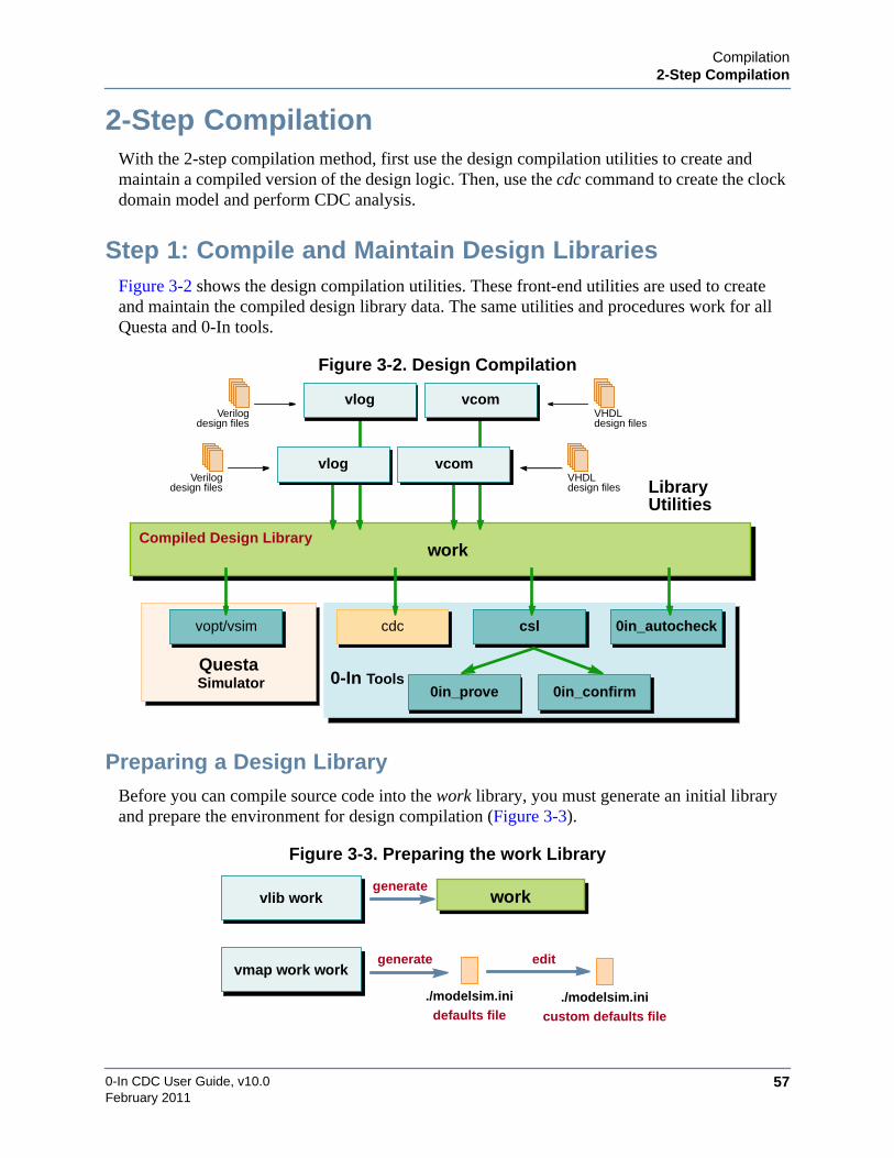
Compilation2-Step Compilation
0-In CDC User Guide, v10.0 57February 2011
2-Step CompilationWith the 2-step compilation method, first use the design compilation utilities to create andmaintain a compiled version of the design logic. Then, use the cdc command to create the clockdomain model and perform CDC analysis.
Step 1: Compile and Maintain Design LibrariesFigure 3-2 shows the design compilation utilities. These front-end utilities are used to createand maintain the compiled design library data. The same utilities and procedures work for allQuesta and 0-In tools.
Figure 3-2. Design Compilation
Preparing a Design LibraryBefore you can compile source code into the work library, you must generate an initial libraryand prepare the environment for design compilation (Figure 3-3).
Figure 3-3. Preparing the work Library
workCompiled Design Library
Verilogdesign files
VHDLdesign files
VHDLdesign files
Verilogdesign files
vlog vcom
vopt/vsim cdc csl 0in_autocheck
0in_prove 0in_confirm
QuestaSimulator 0-In Tools
LibraryUtilities
vlog vcom
workvlib work
./modelsim.ini
generate
defaults file./modelsim.ini
custom defaults file
editvmap work work
generate

0-In CDC User Guide, v10.058
Compilation2-Step Compilation
February 2011
1. Generate the initial library.
prompt> vlib work
2. Map the work directory to the work library.
prompt> vmap work work
The name work is the default working library. A library statement (for work) is notneeded in the source. The work library is the default destination of compiled designunits. So, the above mapping is not necessary. However, the vmap command generates amodelsim.ini file in the current run directory. The modelsim.ini file sets the librarymappings used for simulation by vsim and for CDC compilation/analysis by cdc. It alsosets the default values for compiler and simulator arguments. These default values canbe adjusted, which makes the command argument defaults user-configurable.
3. Edit the modelsim.ini default file to adjust the defaults to fit your environment.
prompt> vim modelsim.ini
The vcom and vlog compilers have an array of compilation parameters that controlexactly how source and resource data are compiled. Some of these compilationparameters can be overridden at compile time by compiler switches. For example, the-2008 argument to vcom directs the compiler to assume VHDL-2008 semantics whencompiling source files. Compilation parameters that are not overridden with compilerswitches assume the “defaults” specified in a modelsim.ini file.
modelsim.ini
The vcom/vlog compilers set $MODEL_TECH to the same directory as$MODEL_TECH_OVERRIDE, if it is defined. Otherwise, they set $MODEL_TECH to thedirectory containing the executable software. To ensure compatibility of software tools, youshould run the compilation commands (vlib, vmap, vcom, vlog, etc.) that are located in the 0-Indistribution software. The 0-In distribution versions of vcom/log set $MODEL_TECH asfollows:
set MODEL_TECH zeroin_install_dir/modeltech/plat
The vcom/vlog design compilers and the cdc clock domain analyzer use the search path shownin Figure 3-4 to find the modelsim.ini file for their compilations.

Compilation2-Step Compilation
0-In CDC User Guide, v10.0 59February 2011
Figure 3-4. modelsim.ini Search Path
Compiling Design FilesAfter initializing the work design library and setting up the modelsim.ini file, you can compiledesign files into the work library (Figure 3-5).
Figure 3-5. Compiling Design Files
Use vcom to compile VHDL style source files and vlog to compile Verilog style (includingSystemVerilog) source code. These compilers have long lists of arguments, but many optionsare used to fine-tune simulation (vsim). Table 3-2 and Table 3-3 show the options that arerelevant to 0-In analysis.
Table 3-2. vcom Syntax
vcom [compile_options] VHDL_file...
VHDL_file… VHDL source files.
compile_options [-work logical_name] [–modelsimini init_file][-87 | -93 | -2002 | -2008] [-explicit][-skipsynthoffregion [-synthprefix keyword]][-check_synthesis] [-noindexcheck | -norangecheck | -nocheck][{-fatal | -error | -warning | -note | -suppress} num[,num]...]...[-source] [-time] [-nowarn number]... [-quiet][-mixedsvvh [b | l | r] [i]] [-pslfile vunit_file]... [-f arg_file]...[other_vcom_options]
$MODELSIM
$MGC_WD/modelsim.ini
./modelsim.ini
$MODEL_TECH/modelsim.ini
$MODEL_TECH/../modelsim.ini
$MGC_HOME/lib/modelsim.ini
prompt> vsim -cQuestaSim> where# Current directory is: /u/cdc_demo# Project is: modelsim.ini
Finding which modelsim.ini file is used
vlog/vcom compilers set $MODEL_TECH internally to the installdirectory for the tool. For 0-In tools, this directory is:
zeroin_install_dir/modeltech/plat
–modelsimini modelsim.ini_file
designfiles vcom/vlog work
append/update
modelsim.ini

0-In CDC User Guide, v10.060
Compilation2-Step Compilation
February 2011
Compile Order
For a Verilog compilation, you can compile almost all compilation units in any order using anynumber of invocations of vlog. When cdc and csl load the compiled design, they resolve modelinstantiations and external hierarchical references. The one case where order matters is:
“SystemVerilog packages must exist for the items they define to be recognized by the scopes inwhich they are imported.” — IEEE Std 1800-2005 LRM
For a VHDL compilation, order matters: you must compile entities/configurations before thearchitectures that reference them.
Resource LibrariesA resource library is a pre-compiled parts source for your design. It is typically a static librarysupplied by a vendor or another design team, but you also can create your own resourcelibraries. Resource libraries are compiled into libraries distinct from work using the samevlib/vmap and vcom/vlog utilities used for compiling the work design library.
The distribution software includes pre-compiled resource libraries for common uses, located in<zeroin_install_dir>/modeltech. The [Library] section of the system-level modelsim.ini file(<zeroin_install_dir>/modeltech/modelsim.ini) shows these resource libraries:
[Library]std = $MODEL_TECH/../stdieee = $MODEL_TECH/../ieeeverilog = $MODEL_TECH/../verilogvital2000 = $MODEL_TECH/../vital2000std_developerskit = $MODEL_TECH/../std_developerskitsynopsys = $MODEL_TECH/../synopsys
Table 3-3. vlog Syntax
vlog [compile_options] Verilog_file...
Verilog_file… HDL source files.
compile_options [-work logical_name] [-libmap file [-libmap_verbose]][–modelsimini init_file] [{-Lf | -L } library]...[-vlog95compat | -vlog01compat][-skipsynthoffregion [-synthprefix keyword]][-skipprotected | -skipprotectedmodule] [-pedanticerrors][-timescale units/precision] [+define{+macro[=value}…][-convertallparams] [+floatparameters[+param_path[.]]][+incdir{+include_dir}…] [+libext{+extension}…][{-fatal | -error | -warning |-note |-suppress} msg[,msg]...]...[-source] [-time] [-nowarnID | -nowarn number]... [-quiet] [-93][-u] [-sv] [-mixedsvvh [b | s | v] [packedstruct]][-mfcu [-cuname comp_unit] | -sfcu] [-pslfile vunit_file]...[-y library_dir] [-v library_file] [–printinfilenames][-f arg_file]... [other_vlog_options]

Compilation2-Step Compilation
0-In CDC User Guide, v10.0 61February 2011
modelsim_lib = $MODEL_TECH/../modelsim_libsv_std = $MODEL_TECH/../sv_stdmtiAvm = $MODEL_TECH/../avmmtiOvm = $MODEL_TECH/../ovm-2.1mtiUPF = $MODEL_TECH/../upf_libmtiPA = $MODEL_TECH/../pa_libfloatfixlib = $MODEL_TECH/../floatfixlibmc2_lib = $MODEL_TECH/../mc2_lib
The [Library] section of the modelsim.ini file shows the library mappings for user-definedlibraries as well. For example, suppose you create a library with the physical location ../shibaand map this library to the logical name my_shiba.
prompt> vlib ../shibaprompt> vmap my_shiba ../shiba
If the local run directory does not already have a modelsim.ini file, vmap copies a version of$MODEL_TECH/../modelsim.ini to the local run directory. Then, vmap updates modelsim.iniwith the new mapping:
prompt> more modelsim.ini. . .[Library]others = $MODEL_TECH/../modelsim.inimy_shiba = ../shibawork = work
If you use vmap to map a library to a logical name that is already mapped in the localmodelsim.ini file, the new mapping simply replaces the old mapping. However, if you edit thelocal modelsim.ini file and specify two library mappings with the same logical name, the file iscorrupt and you get an error when you try to compile.
The others clause in the [Library] section has a special meaning. If a compiler does not find areferenced library in the local modelsim.ini file, but the local modelsim.ini file has an othersclause, the compiler checks the [Library] section of the file specified by others. As with librarymappings, only one others clause is allowed in a modelsim.ini file. However, note that theothers clause provides a method for creating a hierarchy of library mappings because the filereferred in an others clause can contain another others clause, and so on.
Verilog Compilation with Resource Libraries
All modules, interfaces and UDPs instantiated in a Verilog design must be compiled into one ormore libraries. For many designs, you can do this by compiling these design units into the worklibrary along with the design logic. But, all design unit names must be unique in a library, so inthis case all models in work should have unique names. However, many designs require theflexibility of switching among various implementations of cells with the same name or they areso complex that using resource libraries significantly simplify the organization of the designdata. In these cases, you need to use reference libraries. Consider this example:
prompt> vlib work

0-In CDC User Guide, v10.062
Compilation2-Step Compilation
February 2011
prompt> vlib asiclibprompt> vlog -work asiclib and2.v or2.v-- Compiling module and2-- Compiling module or2Top level modules:and2or2prompt> vlog top.v-- Compiling module topTop level modules:top
This example compiles and2 and or2 into the asiclib library and top into work.
When you run vlog to compile the top-level design, the compiler must know the resourcelibraries needed to resolve instantiations and the order that these libraries should be searched (incase multiple libraries contain different versions of the same models). However, instantiationbindings are not determined during compilation; they are determined when you run cdc or csl.So, whatever resource libraries and order specified to vlog should match the libraries and orderused by cdc and csl.
Resource libraries are specified with the –L library and –Lf library options to vlog, cdc and csl.These utilities use the following search order to resolve each instantiation (and they stop at thefirst match):
1. Libraries specified with the –Lf option, in the order they appear in the invocation.
2. The current effective ‘uselib library, if specified.
3. Search path specified in the LibrarySearchPath variable of modelsim.ini (as if theselibraries were specified with the –L argument).
4. Libraries specified with the –L option (searched in the order specified in the invocation).
5. work
6. Library named in the explicit escaped identifier instance name.
Verilog Compilation with Source Libraries
Verilog-XL style compilation is supported. Here, rather than compiling library models intoresource libraries, source libraries (i.e., un-compiled model descriptions) are used to createcompiled models in work. Source libraries are searched after the source files on the commandline are compiled. If any instantiation references are missing, the source libraries are searched incommand-line order. The following Verilog-XL style arguments are recognized by vlog: –v file,–y directory, +libext+suffix, +librescan, +nolibcell and –R simargs.

Compilation2-Step Compilation
0-In CDC User Guide, v10.0 63February 2011
VHDL Compilation with Resource Libraries
VHDL uses library clauses to make objects in reference libraries visible to the current designunit. A library clause appears at the beginning of the design unit and its scope is the region fromthe end of the library clause to the end of the design unit’s declarative region. A use clauseassociated with the library clause can be used to specify which reference library objects arevisible (with the all suffix indicating all objects). For example:
library IEEE;use IEEE.std_logic_1164.all;
The IEEE library is a library of precompiled synthesis and arithmetic packages specially tunedto the Questa/0-In tools. IEEE contains the following packages: math_complex, math_real,numeric_bit, numeric_std, std_logic_1164, std_logic_misc, std_logic_textio, std_logic_arith,std_logic_signed, std_logic_unsigned, vital_primitives and vital_timing. The above clausesspecify that the logical library IEEE is used as a reference library and all declarations in thestd_logic_1164 package are made visible for the scope of the design unit. (For strict IEEEcompliance, the IEEEPURE library contains only the IEEE approved packages.)
Certain libraries are predefined and are visible without explicit specification. The WORK libraryis the current target of the compilation. Design units and packages in WORK are visible. TheSTD library contains the standard, env and textio packages. Both WORK and STD arepredefined and are visible without explicit specification—as if the design units have thefollowing statements:
library STD, WORK;use STD.standard.al
Compiling FPGA Source Libraries
CDC analysis is performed on synthesizable objects in the design: CDC analysis treatsmodules/entities that contain unsynthesizable code as inferred black boxes. In addition, someVHDL FPGA libraries use VITAL constructs. These are not synthesizable, so resource libraryelements containing any of these constructs are inferred as black boxes as well. Some VerilogFPGA libraries contain UDPs, but (unlike VITAL constructs) 0-In compilation automaticallyremodels most of these into synthesizable RTL. However, some Verilog FPGA resource libraryelements model global signals (i.e., signals accessible throughput the design) as hierarchicalreferences to signals in separate top-level blocks outside the DUT. Library elements thatreference global signals in this way are also analyzed as inferred black boxes.
You can manually identify the clock domains of ports of these black boxes—which helps withthe analysis of CDC issues outside the black boxes—but internal clock domain crossinginformation of black boxes is missing. The best solution for CDC analysis is to usesynthesizable libraries.

0-In CDC User Guide, v10.064
Compilation2-Step Compilation
February 2011
Some general-purpose FPGA resource libraries are available in synthesizable form. Theselibraries are often called “formal-friendly” because they are usable with formal model checkerssuch as 0-In Formal and formal equivalence checkers such as FormalPro. They are alsoappropriate for the 0-In CDC analyzer and other tools that need to synthesize a netlist. SomeFPGA vendors (for example, Altera and Actel) include synthesizable libraries in their standarddesign kit installations. Xilinx, however, does not include the synthesizable unisim and simprimlibraries within its standard ISE software installation. Synthesizable resource libraries(optimized for 0-In tools) and other supporting files for two common FPGA library families areincluded with the 0-In distribution software in the following directories:
$HOME_0IN/share/fpga_libs/Altera$HOME_0IN/share/fpga_libs/Xilinx
If the FPGA libraries used for simulation are synthesizable (which is rare except for Verilog-only designs), recompilation of the pre-compiled libraries might not be necessary for CDCanalysis. In all other cases, you must compile an appropriate version of the library source filesfor use with 0-In CDC. When synthesizable FPGA resource libraries are available, you shoulduse them instead of the unsynthesizable libraries optimized for simulation.
The VHDL IEEE, STD and SYNOPSYS libraries are pre-compiled and are automaticallyrecognized by 0-In software. You must compile all other resource libraries using the vcom/vlogcommands on the appropriate FPGA library source files. If you have a VHDL-only design or ifyou have a mixed-language design with library elements instantiated in VHDL, first compilethe VHDL component definitions (but not the VHDL models of the library elements) and thencompile the appropriate Verilog library models.
Step 2: Run CDC Compilation
cdc: Clock Domain Crossing AnalyzerThe cdc command runs within a special shell called the 0in shell (see “0in” on page 347), whichcan run as a batch process or interactively. To run cdc as a batch process, use the -cmd option to0in:
prompt> 0in -cmd cdc cdc_options
The cdc command performs 1-step compilation if necessary, compiles the clock domain modeland performs CDC analysis. Table 3-4 shows the syntax for the cdc command (the 1-stepcompilation options are hidden).

Compilation2-Step Compilation
0-In CDC User Guide, v10.0 65February 2011
Table 3-4. cdc Syntax
cdc –d design[ –report_clock | –report_modes | hier_cdc_options] [–work work_library][{–L | –Lf} library]… [–cuname comp_unit]… [–cache pathname] [options]
–d design HDL design unit to be verified.
–report_clock Report only clock domains and exit. Default: perform full CDCanalysis.
–report_modes Infer all modes of operation or verifies the user-defined modesand exits (without doing any CDC analysis). Generate a modalscript (0in_mode.scr).
hier_cdc_options [–report_hier_scripts | –report_constraints block…| –hier | –hier_block block | –hier_instance instance…| [–hier_cache ILM_cache…][–hier_ctrl_file_model block CFM_ctrl_file]…]
–work work_library Logical name of the design library containing precompileddesign units. Also used as the target library for compilationperformed by cdc. Default: work in the current run directory.
–L library | –Lf library Resource library containing pre-compiled modules for thecompilation.
–cuname comp_unit Name of a compilation unit specified to vlog.
–cache pathname 0in cache directory. Default: same as the 0in shell cachedirectory.
control options [ [–ctrl file]… [–ctrl_list filelist…] [–v95 | –v2k | –sv] ] [–vhctrl control_file]… [–93 | –87 | –2002 | –2008]
| [–ctrl_module module]… ]
reporting options [–cr report_file] [–verbose] [–gen_port_domain_template][–print_all_cdc_paths] [+nowarn{+messageID}…][+error{+messageID}…]
sdc options [–sdc_in sdc_file] [–sdc_out file] [–report_sdc]
advanced options [–de {[mod.]inst_pattern}…] [–di {[mod.]inst_pattern}…][–G name=value]… [–g name=value]… [–mode mode] [–fx][–process_dead_end] [–effort unlimited]
compile cdc assertionsoptions
[–compile_assertions –prefix hierarchy_prefix[–compiled_assertion_report file][–sim {questa | vcs | nc | nc3}] [–sif root_name] [–rel_paths] ]

0-In CDC User Guide, v10.066
CompilationSDC Data
February 2011
SDC DataYou can import an SDC file for the CDC compilation. Each supported SDC command isconverted to an equivalent 0-In global directive. Similarly, you can export an SDC file at theend of CDC compilation and analysis. The relevant global directives, the inferred clocks and theinferred port domains are converted to equivalent SDC commands.
Importing an SDC FileWhen you import an SDC file, supported SDC commands are converted to equivalent globaldirectives (Table 3-5). The SDC version must be 1.6 (or earlier), otherwise an hdl-148 warningis reported. There is no support for design database queries. All signals must be explicitly listedin the SDC file.
You can import SDC data two ways:
• Directly
prompt> 0in -cmd cdc -sdc_in sdc_file ...
The SDC data from sdc_file is converted and used in the CDC compilation.
• Indirectly
prompt> 0in -cmd cdc -report_sdc -sdc_in sdc_file ...prompt> 0in -cmd cdc -ctrl 0in_sdc_ctrl.v ...
The -report_sdc option scans the CDC data and generates a control file (0in_sdc_ctrl.v)containing the global directive equivalents of the relevant SDC commands in sdc_file(Example 3-1). The second invocation of cdc runs CDC compilation and analysis withthe converted SDC constraints.
Table 3-5. Imported SDC Commands
SDC Command Global Directive
create_clock set_cdc_clock
create_generated_clock set_cdc_clock
set_input_delay set_cdc_port_domain
set_output_delay set_cdc_port_domain
set_input_transition set_cdc_port_domain
set_logic_one set_constant
set_logic_zero set_constant
set_case_analysis set_constant
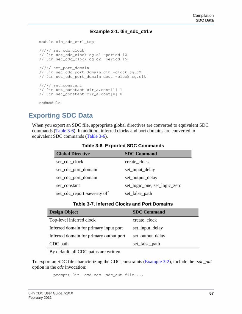
CompilationSDC Data
0-In CDC User Guide, v10.0 67February 2011
Example 3-1. 0in_sdc_ctrl.v
module zin_sdc_ctrl_top;
///// set_cdc_clock// 0in set_cdc_clock cg.c1 -period 10// 0in set_cdc_clock cg.c2 -period 15
///// set_port_domain// 0in set_cdc_port_domain din -clock cg.c2// 0in set_cdc_port_domain dout -clock cg.clk
///// set_constant// 0in set_constant cir_a.cont[1] 1// 0in set_constant cir_a.cont[0] 0
endmodule
Exporting SDC DataWhen you export an SDC file, appropriate global directives are converted to equivalent SDCcommands (Table 3-6). In addition, inferred clocks and port domains are converted toequivalent SDC commands (Table 3-6).
To export an SDC file characterizing the CDC constraints (Example 3-2), include the -sdc_outoption in the cdc invocation:
prompt> 0in -cmd cdc -sdc_out file ...
Table 3-6. Exported SDC Commands
Global Directive SDC Command
set_cdc_clock create_clock
set_cdc_port_domain set_input_delay
set_cdc_port_domain set_output_delay
set_constant set_logic_one, set_logic_zero
set_cdc_report -severity off set_false_path
Table 3-7. Inferred Clocks and Port Domains
Design Object SDC Command
Top-level inferred clock create_clock
Inferred domain for primary input port set_input_delay
Inferred domain for primary output port set_output_delay
CDC path set_false_path
By default, all CDC paths are written.
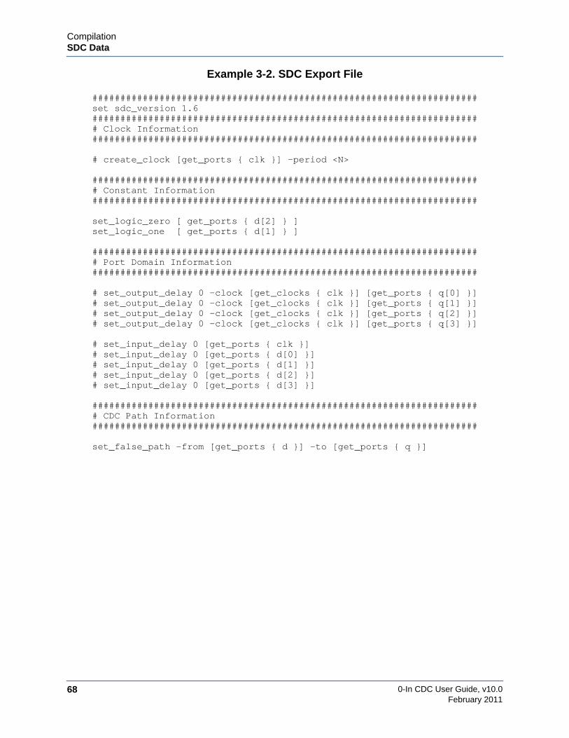
0-In CDC User Guide, v10.068
CompilationSDC Data
February 2011
Example 3-2. SDC Export File
#####################################################################set sdc_version 1.6###################################################################### Clock Information#####################################################################
# create_clock [get_ports { clk }] -period <N>
###################################################################### Constant Information#####################################################################
set_logic_zero [ get_ports { d[2] } ]set_logic_one [ get_ports { d[1] } ]
###################################################################### Port Domain Information#####################################################################
# set_output_delay 0 -clock [get_clocks { clk }] [get_ports { q[0] }]# set_output_delay 0 -clock [get_clocks { clk }] [get_ports { q[1] }]# set_output_delay 0 -clock [get_clocks { clk }] [get_ports { q[2] }]# set_output_delay 0 -clock [get_clocks { clk }] [get_ports { q[3] }]
# set_input_delay 0 [get_ports { clk }]# set_input_delay 0 [get_ports { d[0] }]# set_input_delay 0 [get_ports { d[1] }]# set_input_delay 0 [get_ports { d[2] }]# set_input_delay 0 [get_ports { d[3] }]
###################################################################### CDC Path Information#####################################################################
set_false_path -from [get_ports { d }] -to [get_ports { q }]
CompilationDesign Style Restrictions
0-In CDC User Guide, v10.0 69February 2011
Design Style RestrictionsThe 0-In tools can analyze most design styles seamlessly. However, some design styles andHDL constructs cannot be represented in the CDC analysis model. As cdc compiles the CDCmodel of a DUT, it handles each unsupported design style or construct in one of the followingways:
• The parent module/entity containing the design style is automatically marked as aninferred black box. Output signals of a black box are treated as asynchronous inputs tothe DUT, which can result in extra violations. Mark the module/entity as a user-definedblack box (see “set_black_box” on page 262) to remove these violations. Inputs to blackboxes are reported as blackbox schemes with caution severity, by default.
• The cdc compiler terminates with an error. You must eliminate the error before cdc cancompile the CDC model.
You have the following ways to manually adjust the compilation of the CDC model of a DUT.
• Skipping system calls (+skip_syscall).
The outputs of unknown system calls are ignored. You can get cdc to “skip over” systemcalls when compiling the CDC model. To direct cdc to bypass one or more system callsand omit them from the CDC logic, use the +skip_syscall option to the cdc command.This option has the following syntax:
+skip_syscall{+syscall_name}. . .
• Marking modules as black boxes (set_black_box).
When a module cannot be synthesized and is part of the DUT, it can be skipped bymarking it as a black box. A module is marked as a black box using the followingchecker directive in the checker control file:
// 0in set_black_box module_name
Use the set_cdc_port_domain global directive to identify the clock domains of the I/Oports of these user-defined black boxes.
The following HDL constructs can impact cdc performance, creating long cdc run times andhigh memory consumption.
• Variable bit-selects and variable shifts on large bit-vectors (greater than 1000 bits) usedin nested for-loop statements.
• Large 2-D arrays (greater than 100words) defined in the local scope of a function/task.
• Large numbers of gate-level instances.
• Large numbers of functions or tasks used in nested for-loop statements.

0-In CDC User Guide, v10.070
CompilationDesign Style Restrictions
February 2011
synthesis_off and translate_off Regions
By default, the vlog/vcom compilers do not skip the processing of code inside translate_off andsynthesis_off regions. If you want vlog or vcom to skip translate_off and synthesis_off regions,specify the -skipsynthoffregion command argument. Pragma keywords recognized by thecompilers are: pragma, synopsys, 0in, mentor, mspa, mti and vcs. For example:
-- synopsys synthesis_offsynthesis off block
-- synopsys synthesis_on
-- 0in translate_offtranslate off block
-- 0in translate_on
You also can specify a user-defined translate_off/synthesis_off keyword using the –synthprefixkeyword option to vlog/vcom.
If a design unit is immediately preceded by a translate_off/synthesis_off pragma, the design unitis black-boxed and you get a vopt warning:
** Warning: (vopt-2057): file(line): translate_off pragma active at thestart of entity entity. It BB’es the module.
The translate_off/synthesis_off pragmas reset at the end of the design unit. That is, they areactive until the end of the current design unit or until the terminating pragma, whichever comesfirst. If a translate_off/synthesis_off block crosses a design unit boundary, the code from thepragma to the end of the design unit is skipped, but the code in the next design is elaborated(which is probably not the expected result). When the subsequent translate_on/synthesis_onpragma is reached, an Ignoring pragma warning is reported.
For example, consider the following:
-- synopsys translate_offentity bot ...end entityarch bot ...end archentity top...end entityarch top u1: botend arch-- synopsys translate_on
Here, the bot entity is back-boxed (and the vopt-2057 warning is reported). But the translate_offregion terminates at the end of the bot entity design unit. The bot and top architectures are not inany translate_off region. When translate_on is processed, it is reported as an ignored pragma.

CompilationDesign Style Restrictions
0-In CDC User Guide, v10.0 71February 2011
Most likely, the expected outcome is accomplished by:
-- synopsys translate_offentity bot...end entity-- synopsys translate_on-- synopsys translate_offarch bot...end arch-- synopsys translate_on-- synopsys translate_offentity top...end entity-- synopsys translate_on-- synopsys translate_offarch top u1: botend arch-- synopsys translate_on
override_on/override_off Parser Directives
If you specify -skipsynthoffregion and then want the Questa compilers to process a translate_offor synthesis_off region, enclose the region in the 0in override_on and 0in override_offcomments:
//0in override_on// synopsys translate_offsynthesis translate_off block// synopsys translate_on
//0in override_off

0-In CDC User Guide, v10.072
CompilationDesign Style Restrictions
February 2011
Verilog
The 0-In compilers mark objects containing unsupported code as black boxes or if problems aretoo severe, cdc terminates with errors. By default, all output signals from a black box (and allsignals in the black box) are treated as primary inputs to the DUT. If possible, use ifdefdirectives or remodel the constructs. Table 3-8 shows the unsupported Verilog-95 (-v95) andVerilog 2005 (default) constructs.
Table 3-9 lists the restrictions on the Verilog design styles enforced by the 0-In compilers.
Table 3-8. Unsupported Verilog Constructs
Gates • cmos, nmos, pmos, rcmos, rnmos, rpmos, tran, tranif1, tranif0,rtran, rtranif1, rtranif0, comb, seq, mos.
Statements • forever, while, deassign, force-release, wait, fork, join• for- and repeat-loop statements that are not statically
unrollable.
Numbers • Reals.
Tasks and Functions • Reentrant tasks and recursive functions.• Unknown functions (undefined and predefined system
tasks/functions).
Resets • Unsupported asynchronous reset templates.
Ports • Multiple ports with the same name and inconstantly-definedports (i.e., a port defined by a non-ANSI port definition ormissing port direction/type).
Other Constructs • Events, event declarations and event control assignments.• Disables with hierarchical labels.• Non-constant parameters, loop indexes and part selects.• Different load conditions for memory.• Attributes are partly supported.
Table 3-9. Verilog Design Style Restrictions
Resets • Primary inout ports cannot be used as resets. These are cdcerrors.
• Bused single-bit asynchronous reset are supported but multiple-bit asynchronous reset signals are not. For example, thefollowing code produces an elaboration-541 error (Multi-bitreset signals are not supported) and cdc terminates:
input [0:3] arst_vector;reg r;always @(posedge clk or posedge arst_vector) if (arst_vector) r <= 0; else if (e) r <= d;

CompilationDesign Style Restrictions
0-In CDC User Guide, v10.0 73February 2011
• If an asynchronous reset does not follow one of the followingtemplates, the parent module is marked as a black box):
always @(posedge_negedge clock or posedge areset)if (areset) (. . .)else (. . .)
oralways @(posedge_negedge clock or negedge areset)
if (!areset) (. . .)else (. . .)
Clocks • Primary inout ports cannot be used as clocks. These are cdcerrors.
always Blocks • Memories driven in multiple always blocks are not supported.Their outputs are degraded.
• The same register bit must not be driven in multiple alwaysblocks. The entire register output is degraded. (Individual bitsin a register can be driven in different blocks.)
Tasks and Functions • Tasks and functions should not retain state between calls.• A task or function called from a combo always block or a
function on the RHS of a continuous assign statement cannotmodify a state (register) outside of the task or function.Otherwise, these calls result in simulation/synthesismismatches.
• Functions can call SVA built-in functions (for example, $past).But if the built-in SVA function does not have an explicitclock, the calling Verilog function must have a default clockingblock.
Combinational Loops • Combinational loops are not supported.
RAMs • RAMs with multiple write clocks are not supported. These arecdc errors.
UDPs • Supported: Edge-sensitive sequential UDPs (single clock,single edge), level-sensitive sequential UDPs, combinatorialUDPs. UDPs with notifiers are not black-boxed (notifier row isignored for synthesis).
• Not supported: Multiclock UDPs and UDPs working on boththe edges of a clock.
Race Conditions • Logic has a race condition when the order of arrival of twosignals at a point is indeterminate and the exact arrival orderaffects the design’s state. For example, if a data signal andclock signal arrive simultaneously at a register, the data signalmight, or might not, be clocked at that time. In simulation, theoutcome is simulator-dependent. With CDC analysis, the clocksignal takes precedence.
Table 3-9. Verilog Design Style Restrictions (cont.)

0-In CDC User Guide, v10.074
CompilationDesign Style Restrictions
February 2011
Initial Blocks • Initial blocks are ignored.
Blocking DelayStatements
• Blocking delay statements are compiled without the delays.
bind to VHDL • When a bind statement has a user-defined type, it must bedefined in a VHDL package.
Other Constructs • specify, uselib and ‘resetall statements are ignored.• Selects such as sig[a:b] are only supported if a and b
expressions are constant at elaboration time.• Clashes in variables and instance names should be avoided.
Table 3-9. Verilog Design Style Restrictions (cont.)

CompilationDesign Style Restrictions
0-In CDC User Guide, v10.0 75February 2011
VHDLCompiler support for IEEE 1076-1993 Standard VHDL Language Reference Manual (LRM)constructs is shown in Table 3-10. Unless otherwise noted, each construct in the table iscompletely supported.
Table 3-10. Supported VHDL Constructs
LRM Section 1 Design Entities and Configurations1.11.1.11.1.1.11.1.1.21.1.21.1.3
Entity declarationsEntity header
GenericsPorts
Entity declarative partEntity statement part
1.21.2.11.2.21.31.3.11.3.2
Architecture bodiesArchitecture declarative partArchitecture statement part
Configuration declarationsBlock configurationComponent configuration
LRM Section 2 Subprograms and Packages2.12.1.12.1.1.12.1.1.22.1.1.32.22.32.3.12.3.22.42.52.62.7
Subprogram declarationsFormal parameters
Constant and variable parametersSignal parametersFile parameters
Subprogram bodiesSubprogram overloading
Operator overloadingSignatures
Resolution functionsPackage declarationsPackage bodiesConformance rules
not supported
not supported
LRM Section 3 Types3.13.1.13.1.1.13.1.23.1.2.13.1.33.1.3.13.1.43.1.4.1
Scalar typesEnumeration types
Predefined enumeration typesInteger types
Predefined integer typesPhysical types
Predefined physical typesFloating point types
Predefined floating point typesnot supportednot supported

0-In CDC User Guide, v10.076
CompilationDesign Style Restrictions
February 2011
3.23.2.13.2.1.13.2.23.33.3.13.3.23.43.4.1
Composite typesArray types
Index constraints and discrete rangesRecord types
Access typesIncomplete type declarationsAllocation and de-allocation of objects
File typesFile operations
not supported
not supportednot supportednot supported
LRM Section 4 Declarations4.14.24.34.3.14.3.1.14.3.1.24.3.1.34.3.1.44.3.24.3.2.14.3.2.2
Type declarationsSubtype declarationsObjects
Object declarationsConstant declarationsSignal declarationsVariable declarationsFile declarations
Interface declarationsInterface listsAssociation lists
not supported
4.3.34.3.3.14.3.3.24.44.54.64.7
Alias declarationsObject aliasesNon-object aliases
Attribute declarationsComponent declarationsGroup template declarationsGroup declarations
not supported
not supportednot supported
LRM Section 5 Specifications5.15.25.2.15.2.1.15.2.1.25.2.25.3
Attribute specificationConfiguration specification
Binding indicationEntity aspectGeneric map and port map aspects
Default binding indicationDisconnection specification not supported
LRM Section 6 Names6.16.26.36.46.56.6
NamesSimple namesSelected namesIndexed namesSlice namesAttribute name
Table 3-10. Supported VHDL Constructs (cont.)
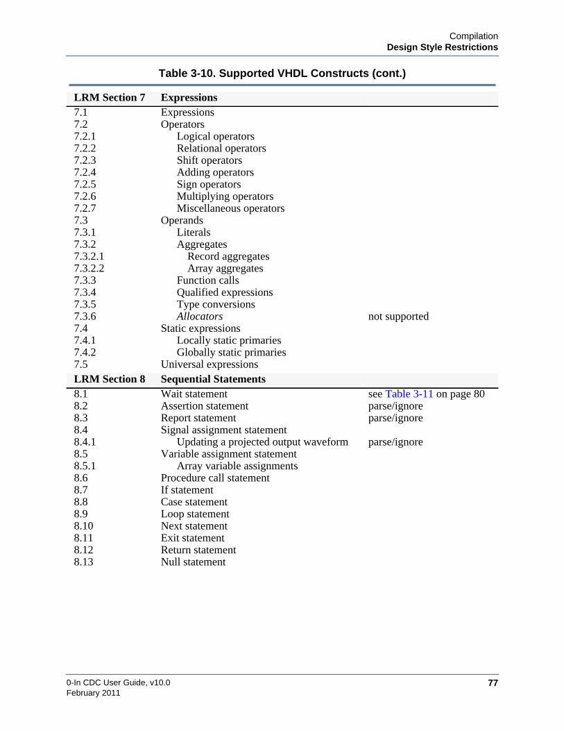
CompilationDesign Style Restrictions
0-In CDC User Guide, v10.0 77February 2011
LRM Section 7 Expressions7.17.27.2.17.2.27.2.37.2.47.2.57.2.67.2.77.37.3.17.3.27.3.2.17.3.2.27.3.37.3.47.3.57.3.67.47.4.17.4.27.5
ExpressionsOperators
Logical operatorsRelational operatorsShift operatorsAdding operatorsSign operatorsMultiplying operatorsMiscellaneous operators
OperandsLiteralsAggregates
Record aggregatesArray aggregates
Function callsQualified expressionsType conversionsAllocators
Static expressionsLocally static primariesGlobally static primaries
Universal expressions
not supported
LRM Section 8 Sequential Statements8.18.28.38.48.4.18.58.5.18.68.78.88.98.108.118.128.13
Wait statementAssertion statementReport statementSignal assignment statement
Updating a projected output waveformVariable assignment statement
Array variable assignmentsProcedure call statementIf statementCase statementLoop statementNext statementExit statementReturn statementNull statement
see Table 3-11 on page 80parse/ignoreparse/ignore
parse/ignore
Table 3-10. Supported VHDL Constructs (cont.)

0-In CDC User Guide, v10.078
CompilationDesign Style Restrictions
February 2011
LRM Section 9 Concurrent Statements9.19.29.39.49.59.5.19.5.29.69.6.19.6.29.7
Block statementProcess statementConcurrent procedure call statementsConcurrent assertion statementsConcurrent signal assignment statements
Conditional signal assignmentsSelected signal assignments
Component instantiation statementsInstantiation of a componentInstantiation of a design entity
Generate statements
not supported
LRM Section 10 Scope and Visibility10.110.210.310.410.5
Declarative regionScope of declarationsVisibilityUse clausesThe context of overload resolution
LRM Section 11 Design Units and Their Analysis11.111.211.311.4
Design unitsDesign librariesContext clausesOrder of analysis
LRM Section 12 Elaboration and Execution12.112.212.2.112.2.212.2.312.2.412.312.3.112.3.1.112.3.1.212.3.1.312.3.1.412.3.1.512.3.1.612.3.1.7
Elaboration of a design hierarchyElaboration of a block header
The generic clauseThe generic map aspectThe port clauseThe port map aspect
Elaboration of a declarative partElaboration of a declaration
Subprogram declarations and bodiesType declarationsSubtype declarationsObject declarationsAlias declarationsAttribute declarationsComponent declarations
Table 3-10. Supported VHDL Constructs (cont.)

CompilationDesign Style Restrictions
0-In CDC User Guide, v10.0 79February 2011
Unqualified constructs in Table 3-10 are completely supported. Other constructs are qualified asfollows:
• not supported
Modules/entities containing constructs identified as not supported are inferred blackboxes.
• parse/ignore
Constructs identified as parse/ignore are recognized and do not cause parsing errors,but no assertion logic is generated for the constructs.
12.3.212.3.2.112.3.2.212.3.2.312.412.4.112.4.212.4.312.4.412.512.612.6.112.6.212.6.312.6.4
Elaboration of a specificationAttribute specificationsConfiguration specificationsDisconnection specifications
Elaboration of a statement partBlock statementsGenerate statementsComponent instantiation statementsOther concurrent statements
Dynamic elaborationExecution of a model
DriversPropagation of signal valuesUpdating implicit signalsThe simulation cycle
not supported
LRM Section 13 Lexical Elements13.113.213.313.3.113.3.213.413.4.113.4.213.513.613.713.813.913.10
Character setLexical elements, separators, and delimitersIdentifiersBasic identifiersExtended identifiersAbstract literalsDecimal literalsBased literalsCharacter literalsString literalsBit string literalsCommentsReserved wordsAllowable replacements of characters
LRM Section 14 Predefined Language Environment14.114.214.3
Predefined attributesPackage STANDARDPackage TEXTIO
Table 3-10. Supported VHDL Constructs (cont.)

0-In CDC User Guide, v10.080
CompilationDesign Style Restrictions
February 2011
Design styles described in Standard for VHDL RTL Synthesis, Section 6.1 “Edge SensitiveSequential Logic” are supported, except as qualified in Table 3-11.
Table 3-11. VHDL Design Style Restrictions
Multiple Clocked Blocks(unsupported styles)
Multiple active clocked blocks in the same process are notsupported. For example:
multiEnableEdgeProc : process(clk, reset)begin
if reset = ’1’ thenQ <= ’0’;
elsif e1 = ’1’ and rising_edge(clk) thenQ <= D11;
elsif e2 = ’1’ and rising_edge(clk) thenQ <= D12;
end if;end process;
The workaround is to model the same functionality using asupported clocking style. For example:
multiEnableEdgeProc : process(clk, reset)begin
if reset = ’1’ thenQ <= ’0’;
elsif rising_edge(clk) thenif e1 = ’1’ then
Q <= D11;elsif e2 = ’1’ then
Q <= D12;end if;
end if;end process;
Multiple Clocked Blocks(supported styles)
One block reachable at a timeMultiple clocked blocks are supported if the compiler determinesthat only one block is reachable at a time. For example:
-- Generic_value is a generic with some value-- Only one of the clocked blocks below is-- reachable in a particular design.multiEnableEdgeProc : process(clk, reset)begin
if Generic_value = ’1’ thenif rising_edge(clk) then
Q <= D11;end if;
elseif rising_edge(clk) then
Q <= D12;end if;
end if;end process;

CompilationDesign Style Restrictions
0-In CDC User Guide, v10.0 81February 2011
Nested blocks with the same clock/edgeNested multiple clocked blocks that use the same clock signal andthe same edge (i.e., posedge or negedge) are supported. Forexample:
multiEnableEdgeProc : process(clk, reset)begin
if reset = ’1’ and rising_edge(clk) thenif reset = ‘1’ then
Q <= ’0’;elsif rising_edge(clk) then
Q <= D12;end if;
end if;end process;
Clock Expressions inProcedures
The use of a clock_expression in a procedure is supported only ifthe procedure that contains the clock_expression is:• Called directly as a concurrent procedure call (calling the
procedure from another concurrent procedure is not supported).• Not called in a sequential scope (for example as a statement
inside a process statement).• Not a recursive procedure.
wait Statements Implicit FSMsImplicit style finite state machines written using multiple waitstatements are not supported. Using a single wait statement with avalid clocking style (as per the LRM) is supported.
Non-static loops using wait statementsNon-static loops with single-clock wait (usually written as implicitstyle state machines using wait statements) are not supported. Forexample:
UartTxFunction : Processbegin
TopLoop : loopwait until rising_edge(clk);
Q <= D;end loop ;
end process ;
Table 3-11. VHDL Design Style Restrictions (cont.)

0-In CDC User Guide, v10.082
CompilationDesign Style Restrictions
February 2011
The following non-static loop with complex conditions is notsupported:
UartTxFunction : Processbegin
TopLoop : loopif (nReset = ’0’) then
SerialDataOut <= ’1’ ;TxRdyReg <= ’1’ ;
end if ;wait until nReset = ’0’ or
(rising_edge(UartTxClk) and DataRdy=’1’);next TopLoop when nReset = ’0’ ;SerialDataOut <= ’0’;TxRdyReg <= ’0’;-- Send 8 Data Bitsfor i in 0 to 7 loop
wait until nReset = ’0’ orrising_edge(UartTxClk);
next TopLoop when nReset = ’0’;SerialDataOut <= DataReg(i) ;TxRdyReg <= ’0’ ;
end loop ;wait until nReset = ’0’ or
rising_edge(UartTxClk) ;next TopLoop when nReset = ’0’;SerialDataOut <= ’1’ ;TxRdyReg <= ’1’ ;
end loop ;end process ;
Selects Selects such as sig(a to b) and sig(a downto b) are only supportedif a and b expressions are constant at elaboration time.
Verilog Configuration Entity/architecture bindings for instances across languageboundaries are not supported. For example: VHDL specifying theconfiguration for a Verilog instance or a VHDL design unitinstantiated in the Verilog part of the design.
User-defined ResolutionFunctions
User-defined resolution functions (i.e., to resolve final values ofthe signals in case of multiple drivers) are ignored. The standardresolution function applied on the standard data type (std_logic) asdefined in the IEEE package is supported.
Tristate Modeling Direct Z assignmentTristate logic modeling through direct ’Z’ assignment on processvariables and inside subprograms is not supported. Tri-statesmodeled through direct ’Z’ assignments in concurrent signalassignments or in processes on signals are supported.
Table 3-11. VHDL Design Style Restrictions (cont.)

CompilationDesign Style Restrictions
0-In CDC User Guide, v10.0 83February 2011
Guard disconnectTristate logic modeling using guard disconnect on std_logic typesignals declared as bus/registers is not supported. For example:
signal dout: Std_Logic bus;-- "bus" yields 3-state;signal flag: Std_Logic;tri_state: block (en = ’1’)begin
dout <= guarded din;flag <= en;
end block;
RAM/ROM Modeling RAM/ROM modeling and inferencing is optimized for the 0-Intools and has better results for the tool usage and characteristics ofthe design. The modeling process ignores some attributes providedin the IEEE rtl_attributes package, including the following:• Ram_block• Rom_block• Logic_block• Certain other pre-defined attributes.
For example, the following attributes are ignored:variable ram : ram_typ; -- ram elementattribute logic_block of ram : variable is TRUE;
VHDL Library Override Except for IEEE standard packages, VHDL libraries can beoverridden. Overrides of IEEE standard packages are ignoredbecause the 0-In native IEEE packages are optimized to improvecompiler performance.
CheckerWare Directives Support for attaching 0-In checker directives to VHDL statementsand objects is shown in Table 3-10 on page 75.
Table 3-11. VHDL Design Style Restrictions (cont.)

0-In CDC User Guide, v10.084
CompilationDesign Style Restrictions
February 2011
Binding to Verilog Design UnitsVHDL names are case insensitive. They are stored in the design and resource libraries in lower-case. Verilog names are case sensitive. They are stored exactly as specified. Ambiguity canoccur when binding to a Verilog design unit from VHDL. Here is the procedure used to select adesign unit from a library:
1. If a design unit exists in the library that has the same name in all lower case, use thatdesign unit.
2. Otherwise, find all design units in the library that have the same case-insensitive name.
• If only one design unit matches, use that design unit.
• If none or multiple design units match, do not use any design unit.
For example, assume VHDL code binds to a design unit named Test.
• work: entity test, module Test
Design unit Test matches entity test (in all lower case). Entity test is used.
• work: module TEST
No design unit is named test (in all lower case). So, the library is searched ignoring case,which finds the single match TEST. Module TEST is used.
• work: module Test, module TEST
No design unit is named test (in all lower case). So, the library is searched ignoring case,which finds the multiple matches: Test and TEST. No design unit is used.

CompilationDesign Style Restrictions
0-In CDC User Guide, v10.0 85February 2011
0-In Directives RestrictionsExpressions in 0-In checker and global directives have the following restrictions:
• Expressions in Verilog control file directives must use Verilog syntax.
• Expressions in VHDL control file directives must use VHDL syntax. In particular,hierarchical references are not supported in VHDL control files.
• Directives with -module arguments cannot use local signals/variables (of the controlmodule).
• Data in quotes must use type qualifiers. For example:
--0in < value -val "000000000000000001" => warning, directive skipped--0in < value -val b"000000000000000001" => OK
--0in < value -val "true" => warning, directive skipped--0in < value -val boolean(true) => OK
• VHDL expressions in directives must be unambiguous. For example, others inaggregates must use type qualifiers:
package pack istype T_1_D_STRAIGHT is array (3 downto 1) of std_logic;type T_2_D_CASCADE is array (2 downto 1) of T_1_D_STRAIGHT;type T_3_D_CASCADE is array (2 downto 1) of T_2_D_CASCADE;type T_3_D_STRAIGHT is
array (2 downto 1, 2 downto 1, 3 downto 1) of std_logic;end;entity e is
port(a : T_3_D_STRAIGHT; b : out T_3_D_STRAIGHT);end;architecture arch1 of test is signal c : T_3_D_STRAIGHT;begin-- 0in custom -fire-- (a = T_3_D_CASCADE’(others =>(others =>(’1’, ’0’, ’1’))))-- -clock clk -name a_all_1_0_1end arch1
0-In CDC User Guide, v10.086
CompilationDesign Style Restrictions
February 2011

0-In CDC User Guide, v10.0 87February 2011
Chapter 4CDC Analysis
Clock domain crossing (CDC) analysis checks the design, infers clock trees, identifies signalsthat cross clock domain boundaries, and detects a variety of synchronization patterns. Theanalysis also suggests CDC checkers for possible inclusion in the design instrumentation.
Figure 4-1. 0-In CDC Tools
CDC GUI
Command-line CDC Tools
0in Shell Tools
CDC Analyzer
Command Helpcwhelp
0in_cdc
interactive(shell)
batch
or
cdc
vlibCompiler Commands
vmapvcomvlog
Shell Commands

0-In CDC User Guide, v10.088
CDC AnalysisCDC Analysis Tools
February 2011
CDC Analysis ToolsAs shown in Figure 4-2, the static 0-In CDC flow starts with a compiled design library. Asdescribed in the previous chapter, you can use the 2-step compilation method (vlog/vcomcommands). Or, under certain restrictions, you can use the 1-step compilation method whereyou pass the design compilation arguments to cdc and (hidden to the user) cdc uses the designcompilation tools to compile the design before it compiles the clock domain model and analyzesthe CDC data.
Figure 4-2. Static 0-In CDC Tool Flow
So, after compiling the design data, the static 0-In CDC tool flow consists of running two toolsin sequence:
1. cdc — compiles the clock domain model and analyzes CDC data.
2. 0in_cdc — displays a suite of GUI tools used to manage and debug the results of CDCanalysis.
0in_cdc: GUI Debug ModeThe 0in_cdc debug tool provides a GUI environment for viewing CDC analysis results,debugging CDC violations and examining CDC check issues. The tool takes a .db file generatedby cdc and shows CDC analysis results in various windows and GUI tools (Figure 4-3 andTable 4-1):
prompt> 0in_cdc 0in_cdc.db
0in -cmd cdc
0in_cdc
designfiles
control
GUI
0in_cdc.db
CDC Debug
Source Code EditorSchematic BrowserCDC Checks Viewer
1-step design libraries
2-step compilation
compilation
Questa Compilersand Library
Management Tools
formal model
Compile design libraries
Compile clock domain
Analyze CDC results
filesmodel

CDC AnalysisCDC Analysis Tools
0-In CDC User Guide, v10.0 89February 2011
Figure 4-3. CDC GUI
Table 4-1. CDC GUI Debug Tools
CDC Checks Window
Shows the results of CDC compilation and analysis. Each CDC schemeinstance has a status flag (page 53) that indicates the status for the CDCinstance. Right-click on a scheme instance to pop up commands fordisplaying various debug windows for inspecting the crossing. Also showsresults merged from simulation and formal verification sessions.
Design Data
Analysis
Debugging Windows
Windows
Windows
Menus Toolbar

0-In CDC User Guide, v10.090
CDC AnalysisCDC Analysis Tools
February 2011
Schematics Viewer
Shows hierarchical schematics for the design. To display the schematicsviewer showing the logic of a CDC instance, right-click on the CDCinstance and run a Show >Schematic command.
Source Code Editor
Provides a dynamic view of the design source code for browsing. Code istightly linked to the GUI objects, which helps navigate the source code. Forexample, right-click on various window objects to show in a source codeeditor: an object’s declaration, an object’s instantiation, an erroneousconstruct flagged in the source code, and other types of constructs flaggedin the source code. The source code editor is also linked to the waveformviewer. As you move the main cursor in the waveform window, theassociated values from the waveform are annotated to the variables in thesource code.
Table 4-1. CDC GUI Debug Tools (cont.)

CDC AnalysisCDC Analysis Tools
0-In CDC User Guide, v10.0 91February 2011
0in_cdc: GUI Project ModeWith the standard CDC verification flow, you compile the design and CDC logic—all as a batchprocess. Then, you load the results into the 0in_cdc GUI to debug CDC violations and explorethe results of CDC analysis. When run this way, 0in_cdc provides a GUI debug environment.An alternate way of running CDC verification is to do all of these steps from within the 0in_cdcenvironment as an interactive GUI session. To do this, run 0in_cdc in project mode (Table 4-2).
Waveform Viewer
Shows waveforms found by simulation with CDC protocol assertions andCDC-FX metastability checkers. Only available for databases merged fromsimulation sessions. To display a waveform, right-click on a CDC instanceand run Show >Simulation Firings.
Table 4-2. 0in_cdc Project Mode Syntax0in_cdc
[[–p project_name ] [hdl_file]… [–d design] [–f verilog_filelist]…[–vhf vhdl_filelist]… [–ctrl verilog_control_file]… [–vhctrl vhdl_control_file]…[–import_ctrl control_file]… [–v95] [–libmapfile library_map_file]… [–y lib_dir]…[–v lib_file]… [–qy lib_skip_dir]… [–qv lib_skip_file]… [–work library][–od output_dir] [–no_directive_error_check] [+libext{+ext}…]…[+incdir{+dir}…]… [+define{+macro[=val]}…]… [–sdc_in sdc_file][–sdc_out file] [–formal] [–cdcid id] [–verbose]
| project_file ]
Table 4-1. CDC GUI Debug Tools (cont.)
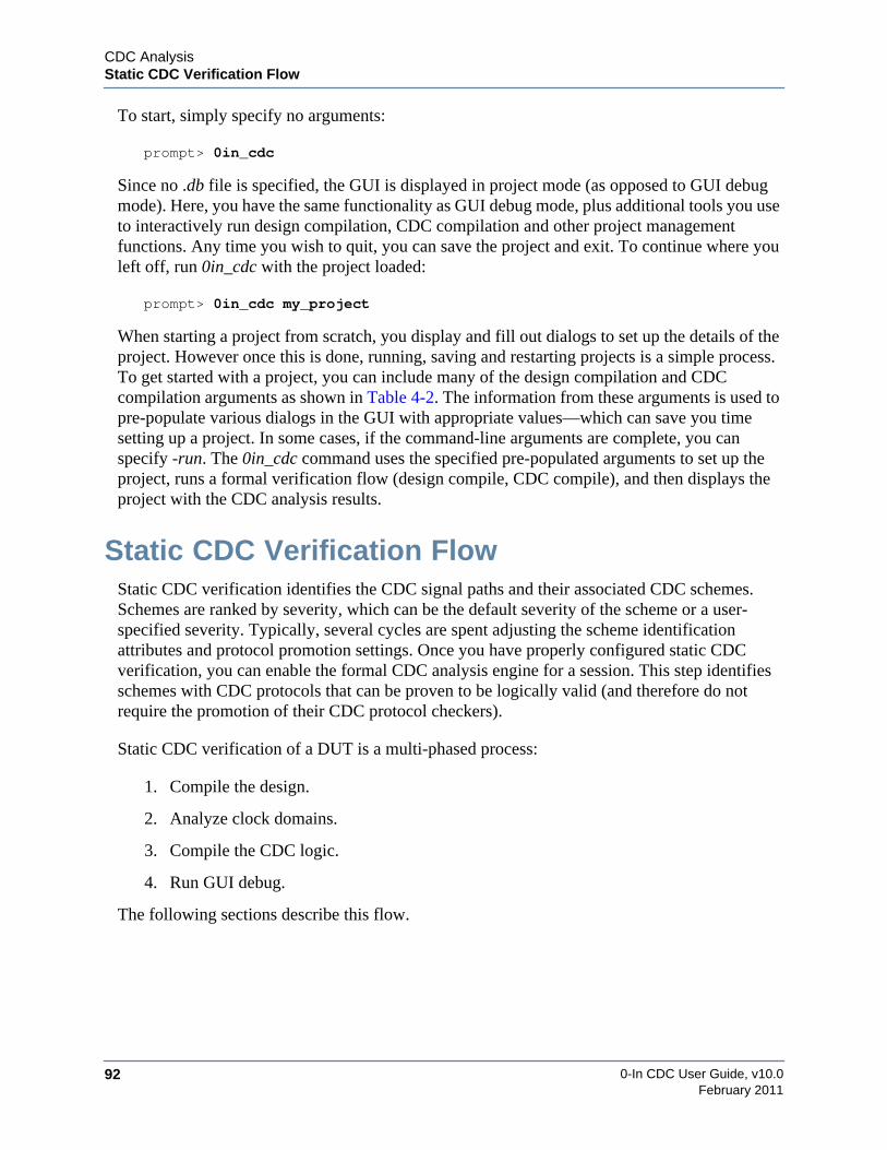
0-In CDC User Guide, v10.092
CDC AnalysisStatic CDC Verification Flow
February 2011
To start, simply specify no arguments:
prompt> 0in_cdc
Since no .db file is specified, the GUI is displayed in project mode (as opposed to GUI debugmode). Here, you have the same functionality as GUI debug mode, plus additional tools you useto interactively run design compilation, CDC compilation and other project managementfunctions. Any time you wish to quit, you can save the project and exit. To continue where youleft off, run 0in_cdc with the project loaded:
prompt> 0in_cdc my_project
When starting a project from scratch, you display and fill out dialogs to set up the details of theproject. However once this is done, running, saving and restarting projects is a simple process.To get started with a project, you can include many of the design compilation and CDCcompilation arguments as shown in Table 4-2. The information from these arguments is used topre-populate various dialogs in the GUI with appropriate values—which can save you timesetting up a project. In some cases, if the command-line arguments are complete, you canspecify -run. The 0in_cdc command uses the specified pre-populated arguments to set up theproject, runs a formal verification flow (design compile, CDC compile), and then displays theproject with the CDC analysis results.
Static CDC Verification FlowStatic CDC verification identifies the CDC signal paths and their associated CDC schemes.Schemes are ranked by severity, which can be the default severity of the scheme or a user-specified severity. Typically, several cycles are spent adjusting the scheme identificationattributes and protocol promotion settings. Once you have properly configured static CDCverification, you can enable the formal CDC analysis engine for a session. This step identifiesschemes with CDC protocols that can be proven to be logically valid (and therefore do notrequire the promotion of their CDC protocol checkers).
Static CDC verification of a DUT is a multi-phased process:
1. Compile the design.
2. Analyze clock domains.
3. Compile the CDC logic.
4. Run GUI debug.
The following sections describe this flow.

CDC AnalysisStatic CDC Verification Flow
0-In CDC User Guide, v10.0 93February 2011
Phase 1. Compiling the DesignIf you use the 1-step method for design compilation, skip this section (got to “Phase 2:Analyzing Clock Domains” on page 93). Otherwise use the compilation utilities to set up,compile and maintain the design libraries (as detailed in “2-Step Compilation” on page 57):
1. Start from a working directory for the project.
For example:
prompt> cd /u/design/zin
2. Create a working library.
prompt> vlib work
3. Name the working library.
prompt> vmap work workCopying /u/0in_3.0/modeltech/linux/../modelsim.ini to modelsim.iniModifying modelsim.ini
Note that a copy of the system modelsim.ini file (page 58) is copied to the run directoryand the local copy is modified to match the arguments of the vmap command.
4. Compile the design files.
Use vcom to compile the VHDL files and vlog to compile the Verilog/SystemVerilogfiles. For example:
prompt> vcom -f pci.fprompt> vlog dut.v
Check the warnings/errors messages and resolve any problems. To see more informationabout a message use the verror command.
prompt> verror -full 2155
MSG_IDX_GLBL_VARS_IN_VERILOGGlobal declarations are illegal in Verilog 2001 syntax.Global declarations are only legal in SystemVerilog. To enableSystemVerilog you can either use the -sv vlog command line switchor give the source file a .sv extension.
Phase 2: Analyzing Clock DomainsOnce the design is compiled, you should identify (and verify) the clock domains before runninga full cdc session to compile and analyze the CDC logic. You do this by creating a control file ofglobal directives that configure CDC analysis and identify the various clocks and clockdomains. Then, you run cdc in a special operational mode called report clocks, which scans thedesign data and reports clock domain information.

0-In CDC User Guide, v10.094
CDC AnalysisStatic CDC Verification Flow
February 2011
1. Set up global directives.
Create one or more control files containing global directives used to configure the CDCanalysis (see “Global Directives” on page 254). Following are some examples:
• Identify clocks’ characteristics (including which clocks belong to the same clockgroups). See “set_cdc_clock” on page 263.
• Override the default clock groups assigned to DUT or instance ports. See“set_cdc_port_domain” on page 276.
• Identify modules/architectures that should be treated as “black boxes” for CDCanalysis. See “set_black_box” on page 262.
• Identify signals that should be considered constant for CDC analysis. See“set_constant” on page 305.
• Identify large memories that are modeled as single sequential elements for CDCanalysis. See “set_memory” on page 308.
• Set the preferences for static CDC analysis. See “set_cdc_preference” on page 283.
• Set severities and promotion properties for CDC scheme types and groups ofschemes. See “set_cdc_report” on page 293.
• Override the classification of various signals and assign them certain CDCproperties. See “set_cdc_signal” on page 299.
Example control file for CDC analysis:
module ctrl;// 0in set_cdc_reconvergence -depth 10 -divergence_depth 1// 0in set_cdc_preference -promote_reconvergence/* 0in set_cdc_report -scheme series_redundant -severity off
-from *_en -tx_clock tx_clk */// 0in set_clock cpu_clk -period 50// 0in set_clock core_clk -period 20// 0in set_clock mac_clk -period 12endmodule
2. Run report clocks.
Run cdc with the -report_clock option. For example:
prompt> 0in -cmd cdc -d dut -ctrl ctrl.v -report_clock
If you use the 1-step method of compiling the design, add the 1-step compilationarguments to the cdc command (as detailed in “1-Step Compilation” on page 56). Forexample:
prompt> 0in -cmd cdc -d dut -ctrl ctrl.v -report_clock \-f design.f +define+mode=initialized -y ../mylib

CDC AnalysisStatic CDC Verification Flow
0-In CDC User Guide, v10.0 95February 2011
3. Check for errors and warnings.
Check the log file (0in_detail.log) for errors and warnings. The Error/WarningSummary table gives the violation count of each type of error/warning.
Error/Warning Summary-----------------------------------------------------------Count Type Message ID Summary-----------------------------------------------------------1 Warning hdl-136 Clock not found in directive.1 Warning hdl-222 Possible dead end CDC paths not reported.3 Warning hdl-41 Primary port connects to multiple clock domains.25 Warning hdl-51 Port domain assignment inferred.
Summary: 30 Warnings in cdc
The detailed error/warning messages are in the body of the log.
prompt> egrep “Error|Warning” 0in_detail.logWarning : Possible dead end CDC paths not reported. [hdl-222]Warning : Clock not found in directive. Directive ’set_cdc_report’,
Module ’demo_top’, Clock ’tx_clk’, File ’cdc_control.v’,Line ’5’. [hdl-136]
Warning : Port domain assignment inferred. Port ’mac_clk_in’, File’top.v’, Line 31. [hdl-51]
Warning : Port domain assignment inferred. Port ’core_clk_in’, File’top.v’, Line 31. [hdl-51]
. . .Warning : Port domain assignment inferred. Port ’rx_check’, File
’top.v’, Line 57. [hdl-51]Warning : Primary port connects to multiple clock domains. Pin
’rst’. [hdl-41]Warning : Primary port connects to multiple clock domains. Pin
’scan_mode’. [hdl-41]Warning : Primary port connects to multiple clock domains. Pin
’scan_clk’. [hdl-41]
4. Check clock domain data.
Check 0in_cdc_design.rpt (see “CDC Design Report” on page 446). This report showsinformation reported by cdc -report_clock such as identified clocks, clock groups andport domain mappings. CDC static analysis resource requirements increase with thenumber of CDC signals identified in the design. Unconfigured CDC analysis canidentify more CDC signals than the design actually has (for example because automaticclock grouping identifies more than the actual number of clock domains). To improveperformance, review and refine the clock trees to achieve the correct grouping. Thefollowing clock data should be accurate after this phase of CDC analysis:
• Clocks are identified correctly — clocks not needed for CDC analysis can beremoved from the clock list.
• Clock groups are identified correctly — clocks can be added and removed from thedifferent clock groups.
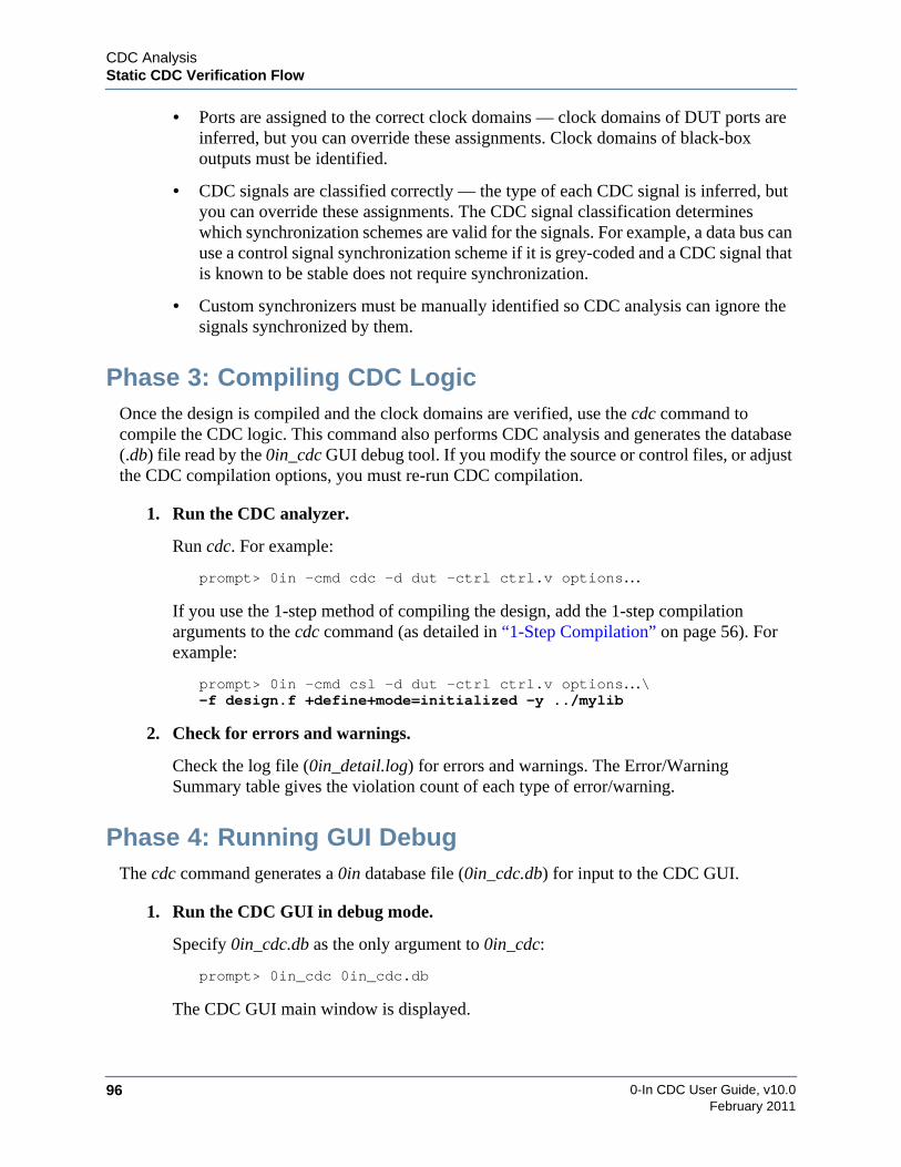
0-In CDC User Guide, v10.096
CDC AnalysisStatic CDC Verification Flow
February 2011
• Ports are assigned to the correct clock domains — clock domains of DUT ports areinferred, but you can override these assignments. Clock domains of black-boxoutputs must be identified.
• CDC signals are classified correctly — the type of each CDC signal is inferred, butyou can override these assignments. The CDC signal classification determineswhich synchronization schemes are valid for the signals. For example, a data bus canuse a control signal synchronization scheme if it is grey-coded and a CDC signal thatis known to be stable does not require synchronization.
• Custom synchronizers must be manually identified so CDC analysis can ignore thesignals synchronized by them.
Phase 3: Compiling CDC LogicOnce the design is compiled and the clock domains are verified, use the cdc command tocompile the CDC logic. This command also performs CDC analysis and generates the database(.db) file read by the 0in_cdc GUI debug tool. If you modify the source or control files, or adjustthe CDC compilation options, you must re-run CDC compilation.
1. Run the CDC analyzer.
Run cdc. For example:
prompt> 0in -cmd cdc -d dut -ctrl ctrl.v options…
If you use the 1-step method of compiling the design, add the 1-step compilationarguments to the cdc command (as detailed in “1-Step Compilation” on page 56). Forexample:
prompt> 0in -cmd csl -d dut -ctrl ctrl.v options…\-f design.f +define+mode=initialized -y ../mylib
2. Check for errors and warnings.
Check the log file (0in_detail.log) for errors and warnings. The Error/WarningSummary table gives the violation count of each type of error/warning.
Phase 4: Running GUI DebugThe cdc command generates a 0in database file (0in_cdc.db) for input to the CDC GUI.
1. Run the CDC GUI in debug mode.
Specify 0in_cdc.db as the only argument to 0in_cdc:
prompt> 0in_cdc 0in_cdc.db
The CDC GUI main window is displayed.
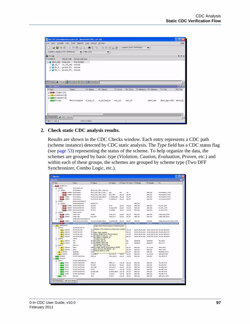
CDC AnalysisStatic CDC Verification Flow
0-In CDC User Guide, v10.0 97February 2011
2. Check static CDC analysis results.
Results are shown in the CDC Checks window. Each entry represents a CDC path(scheme instance) detected by CDC static analysis. The Type field has a CDC status flag(see page 53) representing the status of the scheme. To help organize the data, theschemes are grouped by basic type (Violation, Caution, Evaluation, Proven, etc.) andwithin each of these groups, the schemes are grouped by scheme type (Two DFFSynchronizer, Combo Logic, etc.).

0-In CDC User Guide, v10.098
CDC AnalysisStatic CDC Verification Flow
February 2011
For an initial static CDC session, the basic types are:
• Violation — The path is not an instance of valid CDC scheme. To removethis violation, either the logic must be changed or the violation must be waived (forexample, when the CDC circuit is known to be valid).
• Caution —The path is an instance of a CDC scheme that might or might notbe valid. The CDC interface protocol can possibly be violated. A protocol checkershould be used to check the interface logic. If the scheme type promotes protocolcheckers, one is automatically created (unless promotion is specifically turned offfor the scheme).
• Evaluation —The path is an instance of a valid scheme for the CDC signal.
• Proven — The path is an instance of a valid scheme for the CDC signal andthe CDC interface protocol cannot be violated.
Typically static CDC verification results show proven schemes even when the CDCformal engine is not enabled. For these schemes, the clock ratio of TX/RX clock periodsis < 2 (i.e., the path goes from a domain with a slow clock to one with a fast clock).
3. Fix violations.
Carefully examine the violations. To debug a violation, view the schematic (select thescheme and run Show >Schematic) and view the source code for the violation (runShow >Source). You must rerun static CDC verification if you change the HDL source.
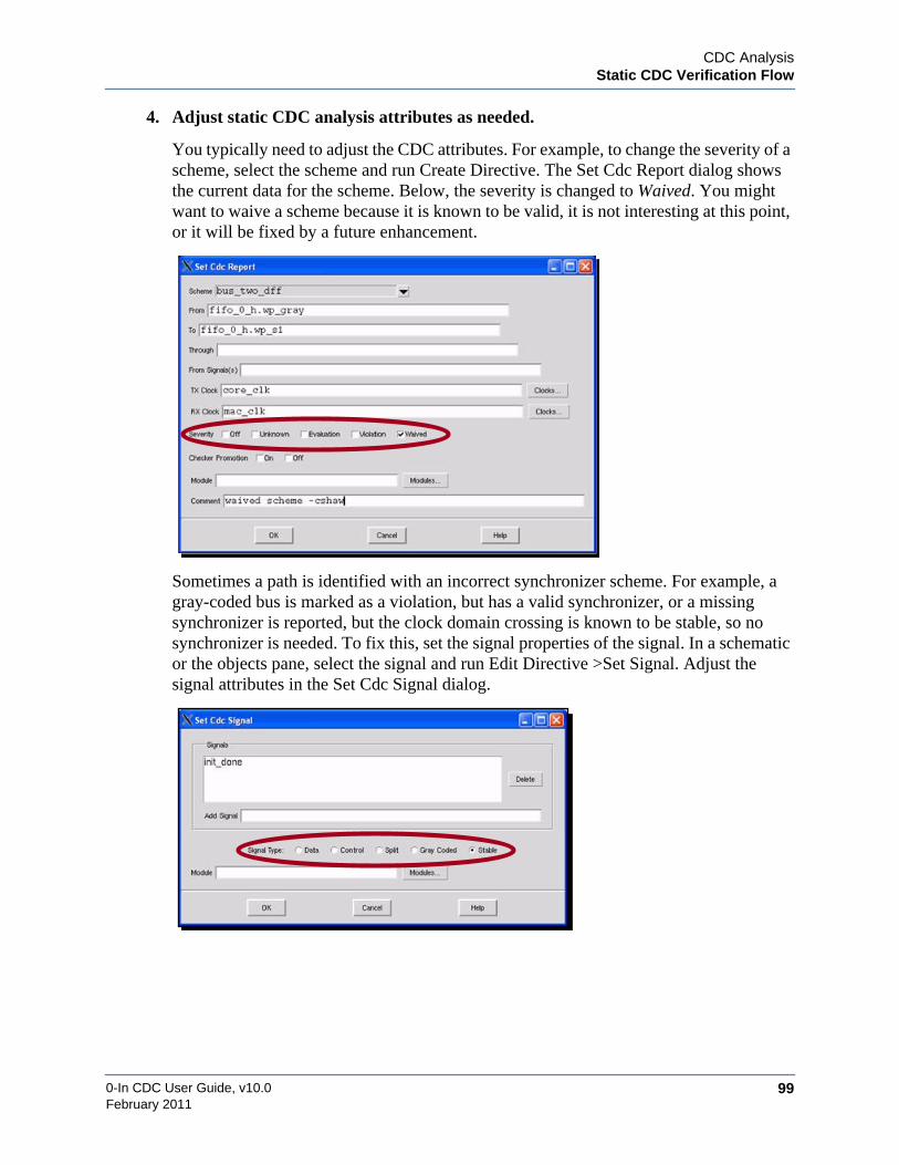
CDC AnalysisStatic CDC Verification Flow
0-In CDC User Guide, v10.0 99February 2011
4. Adjust static CDC analysis attributes as needed.
You typically need to adjust the CDC attributes. For example, to change the severity of ascheme, select the scheme and run Create Directive. The Set Cdc Report dialog showsthe current data for the scheme. Below, the severity is changed to Waived. You mightwant to waive a scheme because it is known to be valid, it is not interesting at this point,or it will be fixed by a future enhancement.
Sometimes a path is identified with an incorrect synchronizer scheme. For example, agray-coded bus is marked as a violation, but has a valid synchronizer, or a missingsynchronizer is reported, but the clock domain crossing is known to be stable, so nosynchronizer is needed. To fix this, set the signal properties of the signal. In a schematicor the objects pane, select the signal and run Edit Directive >Set Signal. Adjust thesignal attributes in the Set Cdc Signal dialog.

0-In CDC User Guide, v10.0100
CDC AnalysisStatic CDC Verification Flow
February 2011
Check the modifications in the directives tab.
Save the current directives as a control file.
File >Export >Directive File.
5. Filter the reporting of static CDC results as needed.
In the previous step, you adjusted how the CDC compiler analyzed specific CDCschemes. Filtering is the process of selecting CDC crossings not to display in the resultspane. Filtered crossings are still analyzed by the CDC compiler—but they are notdisplayed in the CDC Checks window.
To control the filtering process, select an individual CDC crossing or group of CDCcrossings. Running a Filter >Selected popup command displays the Filter CDC Checksdialog. This dialog appears with the currently-filtered items along with the specifiedCDC crossing or group. Which specified crossing or group, is determined by theselection and the particular Filter command used.
Adjust the crossings selected for filtering using this form. Click on OK to accept thecurrent filtering. This removes the crossings from the results pane. To “un-filter” acrossing entry, select any result and run Filter >By Column, which displays the FilterCDC Checks dialog again. Select the crossing you want to restore and then use theDelete (or Modify) button.
You can save the current filtering settings using the Filter >Export popup command andrestore filtering settings from a saved file using the Filter >Import popup command. Thisway, you can organize different groups of CDC issues to help you “filter” outextraneous information as you focus on particular hot spots in your CDC analysis.
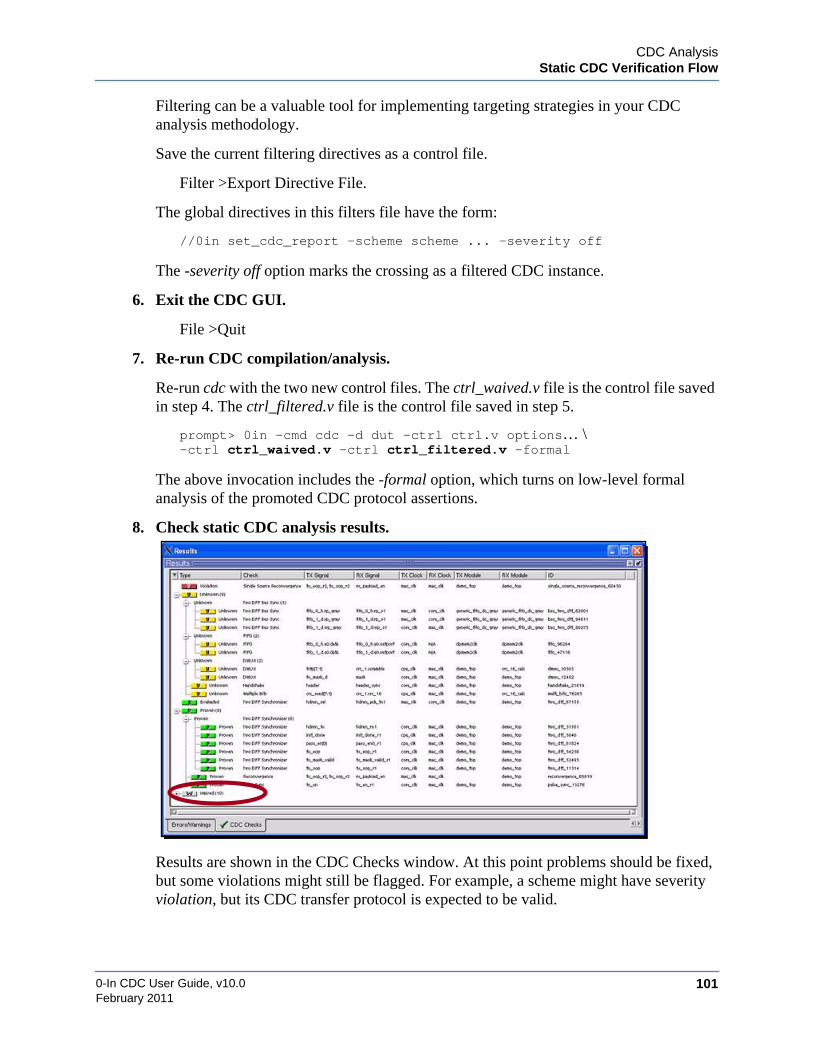
CDC AnalysisStatic CDC Verification Flow
0-In CDC User Guide, v10.0 101February 2011
Filtering can be a valuable tool for implementing targeting strategies in your CDCanalysis methodology.
Save the current filtering directives as a control file.
Filter >Export Directive File.
The global directives in this filters file have the form:
//0in set_cdc_report -scheme scheme ... -severity off
The -severity off option marks the crossing as a filtered CDC instance.
6. Exit the CDC GUI.
File >Quit
7. Re-run CDC compilation/analysis.
Re-run cdc with the two new control files. The ctrl_waived.v file is the control file savedin step 4. The ctrl_filtered.v file is the control file saved in step 5.
prompt> 0in -cmd cdc -d dut -ctrl ctrl.v options… \-ctrl ctrl_waived.v -ctrl ctrl_filtered.v -formal
The above invocation includes the -formal option, which turns on low-level formalanalysis of the promoted CDC protocol assertions.
8. Check static CDC analysis results.
Results are shown in the CDC Checks window. At this point problems should be fixed,but some violations might still be flagged. For example, a scheme might have severityviolation, but its CDC transfer protocol is expected to be valid.

0-In CDC User Guide, v10.0102
CDC AnalysisStatic CDC Verification Flow
February 2011
Since some schemes are marked with waived severity, the Type field has a new group ofentries:
• Waived — The scheme’s severity is manually set to waived.
Schemes with protocols that formal CDC proves are valid are shown with proven status(even waived schemes).
9. Create additional CDC attribute profiles to address specific issues.
The default tuning of the CDC attributes provides a balance between performance andthe effort spent to provide a high level of detail. You can adjust the exact balance byspecifying a CDC attribute profile targeted to specific needs. For example, the followingcontrol file creates a profile that has the minimum compute time and memoryconsumption. This profile is useful for very large designs, especially when workingiteratively to fine-tune results at early stages of verification.
// ctrl_high_performance.v//// High-performance CDC profilemodule ctrl_high_performance;
// Turn off reconvergence checking.// 0in set_cdc_reconvergence -check off
// Turn off exact memory modeling for large memories.// 0in set_memory -abstract mem1 -abstract mem2
// Disable generation of CDC protocol assertions// 0in set_cdc_report -default_promotion off
// Define custom synchronizer modules and identify the clock// domains of the custom synchronizer module pins.// 0in set_cdc_synchronizer custom -module cust_2sync/* 0in set_cdc_port_domain in1 out2 -clock clk1
-module cust_2sync *//* 0in set_cdc_port_domain in2 out1 -clock clk2
-module cust_2sync */
// Black-box modules that are not required for CDC analysis// 0in set_black_box modX
endmodule // ctrl_high_performance
For extremely large designs, use a hierarchical CDC verification flow (see “HierarchicalCDC Analysis” on page 118).

CDC AnalysisStatic CDC Verification Flow
0-In CDC User Guide, v10.0 103February 2011
The following example control file creates a profile that provides a higher level of detailin the checking and reporting of CDC data.
// ctrl_high_accuracy.v//// High-accuracy CDC profilemodule ctrl_high_accuracy;
// Enable divergence checking and set reconvergence checking to// a greater depth (default is 0). Start with a depth of 1.// 0in set_cdc_reconvergence -divergence_depth 1 -depth 1
// Enable reconvergence reporting for paths thru// DMUX synchronizers.// 0in set_cdc_preference -dmux_as_recon_start
// Enable FIFO and handshake scheme checking:// 0in set_cdc_preference -fifo_scheme -handshake_scheme
// Report disabled CDC paths.// 0in set_cdc_preference -filtered_report
// Enable constant propagation through sequential elements.// 0in set_constant_propagation -latch
endmodule // ctrl_high_accuracy
Also, consider the following:
• Define all clock periods using set_cdc_clock and turn on formal CDC analysis withthe cdc command-line switch -formal. Start with the default -formal_effort (low).
• Turn on reporting of patch to dead-end nodes using the cdc command-line switch-process_dead_end.
• Use modal analysis to check all modes of clocking (see “Modal CDC Analysis” onpage 133).

0-In CDC User Guide, v10.0104
CDC AnalysisDynamic CDC Verification Flow
February 2011
Dynamic CDC Verification FlowDynamic CDC analysis consists of running user-defined simulation tests in your standardsimulation environment, with the added logic created by 0-In tools. This added logic is derivedfrom CDC protocol assertions, metastability injection logic, or both. To compile this logic, usethe –compile_assertions option to the cdc command and specify the location of the DUT in thetestbench using the –prefix hierarchy_prefix argument. The results of simulation with CDCprotocol assertions can be merged with the static CDC database.
CDC Protocol AnalysisDuring static CDC verification, the formal CDC engine proved the CDC protocols are valid forsome schemes with basic protocols. But, the CDC transfer protocols for caution schemes mustbe verified explicitly. Some scheme types have general characteristics that are readily verifiedby checkers in the 0-In CDC assertion library (Table 4-3). To test and verify the protocols forthese schemes, static CDC analysis “promotes” protocol checkers for CDC protocol analysis.The promoted checkers are written to the 0in_cdc_control.v control file by default during staticCDC analysis.
The CDC checkers are modules that ensure that data crossing clock domain boundaries aretransmitted and received correctly. The CDC checkers are implemented the same as otherCheckerWare checkers. They monitor the design during assertions in simulation. Their checkscan be targets for formal verification. They are instantiated directly by using checker directives.
Table 4-3. CDC Protocol CheckersChecker Type Protocolcdc_sync Ensures that a clock domain crossing signal from a faster
clock to a slower clock is held stable long enough for thesignal to be sampled reliably by the receiver.
cdc_sample Ensures that receive data between two clock domainsremain stable in the transmit domain for one receive clockcycle before and one receive clock cycle after it is sampledin the receive domain. The receive domain samples at leasttwice for each transmit signal so that the correct value issampled.
cdc_dsel Ensures that a signal between two clock domains, where thetransmitter’s data select signal drives the select input of adata multiplexer in the receiver, is held stable enough for thesignal to be sampled reliably by the receiver and ensuresthat the data remains stable while the data select signalasserts.
cdc_handshake_data Ensures that the handshaking protocol between transmitterand receiver is correctly followed, and ensures that thetransmit data remains stable in the data transfer window.

CDC AnalysisDynamic CDC Verification Flow
0-In CDC User Guide, v10.0 105February 2011
Using the generated promoted CDC checker control file, you analyze the CDC transferprotocols in either or both of the following ways:
• Run formal verification with the promoted CDC protocol checkers.
• Run simulation with the promoted CDC protocol checkers.
Checkers for the protocols verified by the formal CDC engine are not promoted, so formalanalysis and simulation do not waste cycles analyzing pre-verified protocols. Standard 0-InCDC checkers can be manually added for cases where the schemes’ protocols match theprotocols verified by the checkers. Custom assertions checkers can be created for othersituations. Simulation and formal results for these checkers are not imported back into the CDCGUI, so problems must be debugged in those environments. CDC-FX metastability analysisalso uncovers issues with protocols with inconclusive results.
0-In Formal VerificationThis step is optional and requires significant setup for formal analysis (such as adding aninitialization sequence and formal check assumptions).
0-In Prove formal verification analyzes the promoted CDC protocol checkers and identifiesthose protocols that it proves cannot be violated. The results of the formal analysis are thenmerged with the results of static CDC verification to show the progress of analyzing the CDCprotocols.
1. Check the control file of promoted CDC protocol checkers.
Examine 0in_cdc_ctrl.v in the directory containing the results of static CDC analysis.Check the contents of the control file. If you make adjustments, save the file to adifferent name to prevent the changes from being overwritten the next time you runstatic CDC analysis.
2. Run formal verification.
Set up a run script for formal verification with the promoted control file. For example,the following Makefile entry runs the 0-In csl formal model compiler and then0in_prove.
cdc_hamming_distance_one Ensures that the data crossing from transmit clock to receiveclock domain changes by only one hamming distance andthat it remains stable for a specified tx_min clock cycles.
cdc_fifo Ensures that the write and read pointers of an asynchronousFIFO change by hamming distance one, and ensures that theFIFO does not overflow or underflow.
cdc_glitch Ensures that a specified register does not have a glitch in itsinput.
Table 4-3. CDC Protocol CheckersChecker Type Protocol
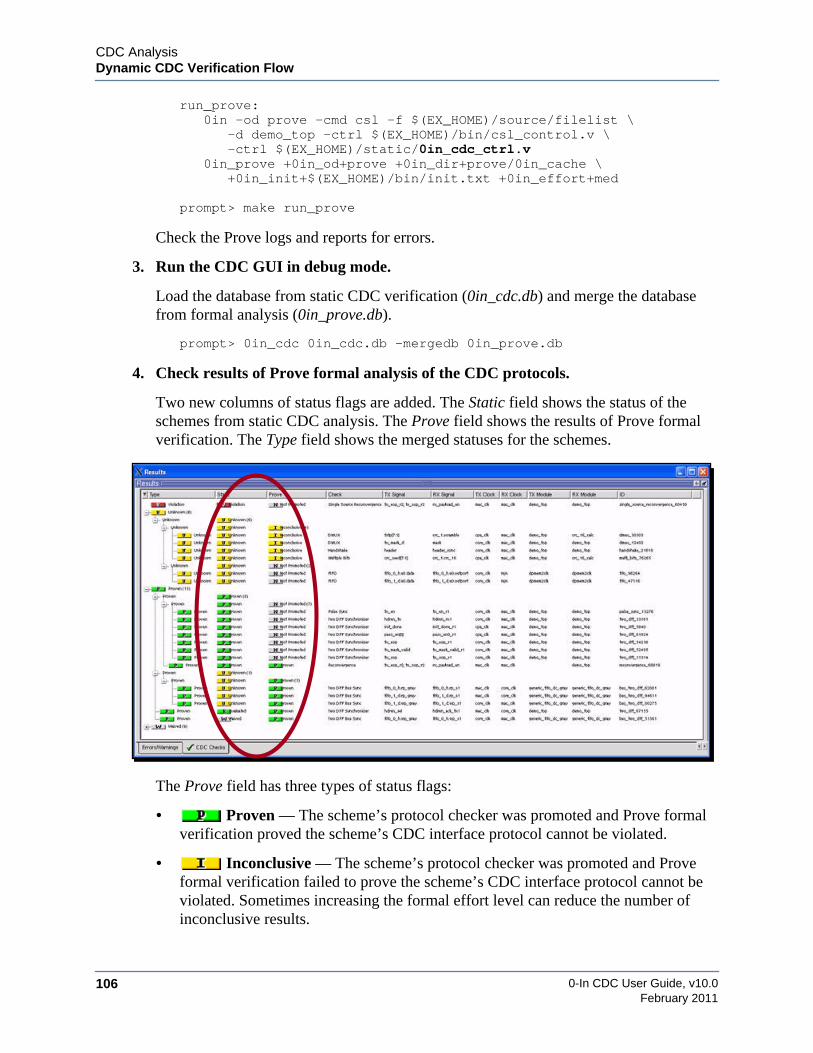
0-In CDC User Guide, v10.0106
CDC AnalysisDynamic CDC Verification Flow
February 2011
run_prove:0in -od prove -cmd csl -f $(EX_HOME)/source/filelist \
-d demo_top -ctrl $(EX_HOME)/bin/csl_control.v \-ctrl $(EX_HOME)/static/0in_cdc_ctrl.v
0in_prove +0in_od+prove +0in_dir+prove/0in_cache \+0in_init+$(EX_HOME)/bin/init.txt +0in_effort+med
prompt> make run_prove
Check the Prove logs and reports for errors.
3. Run the CDC GUI in debug mode.
Load the database from static CDC verification (0in_cdc.db) and merge the databasefrom formal analysis (0in_prove.db).
prompt> 0in_cdc 0in_cdc.db -mergedb 0in_prove.db
4. Check results of Prove formal analysis of the CDC protocols.
Two new columns of status flags are added. The Static field shows the status of theschemes from static CDC analysis. The Prove field shows the results of Prove formalverification. The Type field shows the merged statuses for the schemes.
The Prove field has three types of status flags:
• Proven — The scheme’s protocol checker was promoted and Prove formalverification proved the scheme’s CDC interface protocol cannot be violated.
• Inconclusive — The scheme’s protocol checker was promoted and Proveformal verification failed to prove the scheme’s CDC interface protocol cannot beviolated. Sometimes increasing the formal effort level can reduce the number ofinconclusive results.
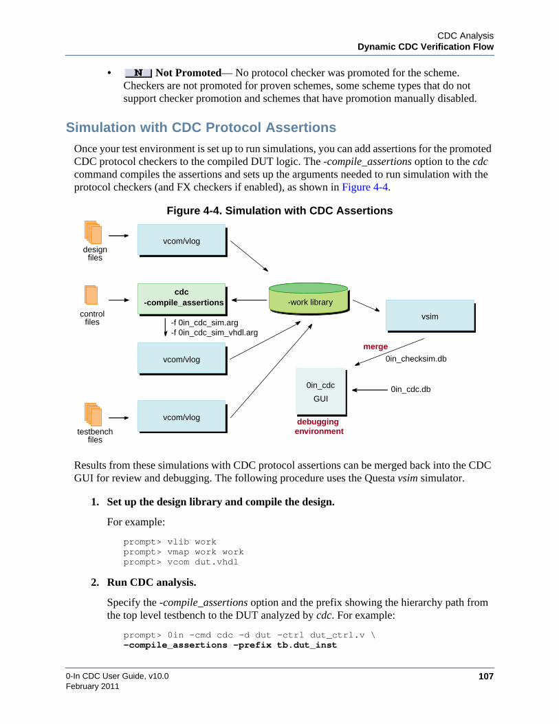
CDC AnalysisDynamic CDC Verification Flow
0-In CDC User Guide, v10.0 107February 2011
• Not Promoted— No protocol checker was promoted for the scheme.Checkers are not promoted for proven schemes, some scheme types that do notsupport checker promotion and schemes that have promotion manually disabled.
Simulation with CDC Protocol AssertionsOnce your test environment is set up to run simulations, you can add assertions for the promotedCDC protocol checkers to the compiled DUT logic. The -compile_assertions option to the cdccommand compiles the assertions and sets up the arguments needed to run simulation with theprotocol checkers (and FX checkers if enabled), as shown in Figure 4-4.
Figure 4-4. Simulation with CDC Assertions
Results from these simulations with CDC protocol assertions can be merged back into the CDCGUI for review and debugging. The following procedure uses the Questa vsim simulator.
1. Set up the design library and compile the design.
For example:
prompt> vlib workprompt> vmap work workprompt> vcom dut.vhdl
2. Run CDC analysis.
Specify the -compile_assertions option and the prefix showing the hierarchy path fromthe top level testbench to the DUT analyzed by cdc. For example:
prompt> 0in -cmd cdc -d dut -ctrl dut_ctrl.v \-compile_assertions -prefix tb.dut_inst
vcom/vlog
vcom/vlog
vcom/vlog
cdc
0in_cdc
controlfiles
designfiles
GUI
debuggingenvironment
-work library-compile_assertions
-f 0in_cdc_sim.arg-f 0in_cdc_sim_vhdl.arg
vsim
testbenchfiles
0in_checksim.db
0in_cdc.db
merge

0-In CDC User Guide, v10.0108
CDC AnalysisDynamic CDC Verification Flow
February 2011
3. Compile the protocol assertions.
Specify the simulation arguments files generated by cdc. For example:
prompt> vlog -f 0in_cdc_sim.argprompt> vcom -f 0in_cdc_sim_vhdl.arg
4. Compile the testbench.
prompt> vlog tb.v
5. Run simulation.
Specify the PLI library path for the simulator and the vsim arguments files. For example:
prompt> vsim -c tb -pli $HOME_0IN/lib/lib0InLoadMTIPLI.so \-f 0in_cdc_sim.arg.vsim -f 0in_cdc_sim.arg.vsimrun \-do "add log -r /*; run 1000; quit -f"
6. Run the CDC GUI.
Load the 0in_cdc.db database generated by cdc and merge the 0in_checksim.db databasegenerated by vsim.
prompt> 0in_cdc 0in_cdc.db -mergedb 0in_checksim.db
7. Check results of simulation with the CDC protocol assertions.
One new column of status flags and four new columns of simulation results are added.The Simulation field shows the status of the schemes from simulation. The Type fieldshows the merged statuses for the schemes. The Simulation field has five types of statusflags:
• Firing — Simulation violated the scheme’s protocol. The Firings fieldshows the number of firings (number of times the protocol was violated) and FirstFiring shows the testbench time of the first violation.
• Unevaluated — Simulation never activated the scheme’s protocol assertion.
• Evaluated — Simulation activated the scheme’s protocol assertion. TheEvaluations field shows the number of cycles the protocol assertion activated.
• Covered — Simulation covered all of the scheme’s protocol assertion’scover points.
• Not Promoted— No protocol checker was promoted for the scheme.Checkers are not promoted for proven schemes, some scheme types that do notsupport checker promotion and schemes that have promotion manually disabled.
Schemes with violation severity are promoted. Similarly, protocol assertions that areactivated in simulation (Evaluated) might not be covered in simulation. So, twoadditional status flags are possible in the merged status (Type field):

CDC AnalysisDynamic CDC Verification Flow
0-In CDC User Guide, v10.0 109February 2011
• Violation and Firing — Scheme is a violation and the scheme’s protocolwas violated during simulation.
• Not Covered — Simulation activated the scheme’s protocol assertion, butsimulation did not exercise all the assertion’s cover points.
8. Debug protocol assertion firings.
Select the scheme and run Show >Simulation Firings. From the Firings dialog, select thedesired firing. In the Load Waveform Database dialog, find the generated waveform file.

0-In CDC User Guide, v10.0110
CDC AnalysisDynamic CDC Verification Flow
February 2011
Use the waveform view, the schematic view and the source code editor to track downand fix the source of the firings.

CDC AnalysisDynamic CDC Verification Flow
0-In CDC User Guide, v10.0 111February 2011
9. Check CDC assertions that are not covered.
Check results that are Not Covered. Select a crossing and run the Show >ProtocolChecker popup command. The Checksim window is displayed with the entry for theselected protocol checker highlighted.
Typically, you modify simulation or run CDC protocol checking with additional tests toensure complete coverage of the relevant CDC protocol assertions.
CDC-FX Metastability AnalysisSimulation tests used for simulation with CDC protocol assertions can be re-used for CDC-FXmetastability analysis. For these simulations, the compiled design is extended with CDC-FXmetastability injection logic, which causes the simulated design to behave like a hardwareimplementation with random metastability effects. End-to-end tests that pass under normalsimulation can fail when simulated with metastability effects, unless the design is “metastabilityhardened.”
A clock domain crossing is metastability hardened if transmit values always are held stablearound receive clock edges whenever the active edges of the transmit and receive clocks“align.” Here, the two clocks are considered aligned if the active transmit clock edge falls in a“metastability window” around an active receive clock edge. By default, this window is set at25% before the receive clock edge to 10% after the edge, but the sizes and skews ofmetastability windows can be adjusted to accommodate clocking and physical designcharacteristics. Crossings that are guaranteed to be stable when active clock edges align, do notproduce metastable values, so these paths are simulated the same in both regular simulation andsimulation with CDC-FX injectors. The injectors on these paths are never activated andtherefore never simulate metastability.
However, clock domain crossings that can legally become metastable also can be consideredmetastability hardened. In these cases, the receive logic must account properly for the randomdelays and advances that can occur as a result of the metastability effects exhibited by thecrossings and their reconverging logic. For these crossings, CDC-FX simulation randomlyinjects metastability by delaying or advancing various value changes that occur when transmitand receive clocks align in their metastability window.
Simulating the design with random metastability in this way tests that all clock domaincrossings are metastability hardened. If these simulation tests adequately exercise the design to

0-In CDC User Guide, v10.0112
CDC AnalysisDynamic CDC Verification Flow
February 2011
cover the various possible signal crossing situations, a truly metastability hardened design willpass—indicating a high level of confidence that the design’s hardware implementation will notexhibit faults arising from metastability. Alternatively, a well-constructed test suite simulatedwith metastability effects will detect unhardened CDC paths and logic by producing end-to-endtest failures. These you debug the same way as with standard simulation by analyzing backwardfrom the miscompared outputs using your simulation waveforms and debug environment.
Running Simulation with CDC-FX Metastability Injection1. If needed set up global directives for setting metastability windows.
The following control module shows a control file that sets the FX timescale andmetastability windows (see “Metastability Windows” on page 160) for wr_clk-to-rd_clkcrossings and rd_clk-to-wr_clk crossings.
prompt> more fx_ctrl.vmodule fx_ctrl;
// 0in set_cdc_fx_timescale 1ps/1ps/* 0in set_cdc_fx_metastability_window
-start 5000 -stop 1000 -rx_clock wr_clk -tx_clock rd_clk *//* 0in set_cdc_fx_metastability_window
-start 6000 -stop 1000 -rx_clock rd_clk -tx_clock wr_clk */endmodule
2. Compile and analyze the design.
The same setup used for simulation with CDC protocol assertions can be adapted forCDC-FX simulation—with two modifications to the cdc invocation:
• Add the -fx argument, which generates the CDC-FX metastability injection logic.
• Add the control file containing the CDC-FX directives.
For example:
prompt> vlib workprompt> vmap work workprompt> vcom dut.vprompt> 0in -cmd cdc -d dut -ctrl dut_ctrl.v –fx -ctrl fx_ctrl.v\-compile_assertions -prefix tb.dut_instprompt> vlog -f 0in_cdc_sim.argprompt> vcom -f 0in_cdc_sim_vhdl.argprompt> vlog tb.v
3. Run simulation.
For example:
prompt> vsim -c tb -pli $HOME_0IN/lib/lib0InLoadMTIPLI.so \-f 0in_cdc_sim.arg.vsim -f 0in_cdc_sim.arg.vsimrun \-do "add log -r /*; run 1000; quit -f"
Debug issues in the simulator debug environment as with standard simulations.

CDC AnalysisDynamic CDC Verification Flow
0-In CDC User Guide, v10.0 113February 2011
4. Check CDC–FX checkers that are not covered.
Load the results of simulation with CDC-FX checkers into the CDC GUI:
prompt> 0in_cdc 0in_cdc.db -mergedb 0in_checksim.db
Check results that are Not Covered in the Checksim window.
Select a crossing and run Show >Coverage.
In this example, the All Bits Metastable cover points show only 11 out of 32 bits aretested with metastability injection. Typically, you modify simulation or run additionaltests to ensure complete coverage of the CDC-FX checkers.
Simulation ArgumentsTable 4-4 shows additional arguments you can include in your simulator invocation when yourun simulation with CDC protocol checkers and CDC-FX checkers.
Table 4-4. Simulator Arguments
simulator_cmd simulator_args–f sim_arg_file [+0in_no_checksim_db] [+0in_checker_finish_delay+time][+define+prefix_0in=prefix] [+0in_db+file] [+0in_firing_limit+limit][+0in_signature_limit+limit] [+0in_no_violation_limit] [+0in_firing_keyword+keyword][+0in_licq] [+0in_od+output_dir] [+0in_no_statistics] [+0in_covered_report[+file]][+0in_simulation_message_limit+limit] [+0in_no_simulation_messages] [–version][+0in_suppress_fx_name{+name}…] [+0in_disable_fx_force] [+0in_random_seed+n]

0-In CDC User Guide, v10.0114
CDC AnalysisDynamic CDC Verification Flow
February 2011
simulator simulator_args Simulator invocation for the design and testbench, includingHDL simulator arguments.
–f sim_arg_file File (generated by ccl or csl) with the simulator arguments forrunning simulation with assertions
+0in_no_checksim_db Turns off generation of the viewer database created by simulationwith assertions. Default: 0in_checksim.db.
+0in_checker_finish_delay+time
Number of time units to continue simulation with assertionsbefore exiting after a firing (in response to a set_checker_action –finish directive). Default: 10 time units.
+define+prefix_0in=prefix Changes the hierarchy prefix if needed for the target designspecified using the –d option in ccl/csl.
+0in_db+file Name of the generated viewer database. Default: 0in_tool.db(tool = prove | confirm).
+0in_firing_limit+limit Maximum number of firings in the viewer database. Default: 10.
+0in_signature_limit+limit Maximum number of signatures per check in the viewer database.Default: 10.
+0in_no_violation_limit Removes the limits on firings per signature and signatures percheck in the viewer database.
+0in_firing_keyword+keyword
Adds keyword to each firing message, so each firing messagebegins with: 0-In keyword FiringDefault: Each firing message begins with: 0-In Firing.
+0in_licq Enables license queuing. Default: tools terminate if requiredlicenses are in use.
+0in_od+output_dir Directory to store all output files. Default: current directory.
+0in_no_statistics Turns off statistics computation and reporting during simulation.
+0in_covered_report[+file] Generates a structural coverage report. Default file name:0in_covered.rpt.
+0in_simulation_message_limit+limit
Number of firings per signature reported to the simulation logand STDOUT. Default: 1.
+0in_no_simulation_messages
Turns off reporting checker firing messages to the simulation logand STDOUT.
–version Reports the software release version and copyright informationand exits.
+0in_suppress_fx_name{+name}…
Suppresses CDC-FX metastability injection for the specifiedregisters.
+0in_disable_fx_force Suppresses CDC-FX metastability injection for all registers.
+0in_random_seed+n Sets the seed for random metastability injection.
Table 4-4. Simulator Arguments

CDC AnalysisDynamic CDC Verification Flow
0-In CDC User Guide, v10.0 115February 2011
Compiling with ccl for SimulationThe -compile_assertions option configures the setup for simulation with CDC and CDC-FXcheckers. For some situations, you need to run the ccl compiler instead to do this. Table 4-5shows syntax for this 0in shell command.
Table 4-5. ccl Syntax
ccl[–fastsim [turbo]] [–fastmod [module]] [–race_avoid] [–incr] [–incremental_firing_db][–ac_stats] [–cuname comp_unit] [–psl] [–pslfile_vl verilog_vunit_file]…[–pslfile_vh vhdl_vunit_file]…[–ovl] [–ovl_cover] [–sim {questa | mti | vcs | nc | nc3}][–full] [–rel_paths] [–prove_checkers] [–use_synthesis_case_directives] [–rcd][–rcd_file file] [–rcd_level level] [–sif simulation_arg_file] [–unique_names][–exit_on_directive_errors] [verilog_options] [vhdl_options] [rtl_options][reporting_options] [compile_options]
–fastsim [turbo] Creates checker logic without structural coverage logic, sosimulation with assertions runs in high performance mode. Theturbo option optimizes the checker logic further to increasesimulation performance. Default: checker logic includesstructural coverage logic, which decreases simulationperformance.
–fastmod [module] Creates checker logic with checkers moved up to the specifiedmodule, connected with collapsed nets. The top module is used ifmodule is unspecified. This option can further increasesimulation performance. Default: checkers are instantiated intheir defining modules.
–race_avoid Avoids race conditions during simulation. However, using thisoption can slow down simulation.
–incr Generates checker logic files incrementally, which can improvecompile time by preventing recompilation of unchanged checkerfiles. Default: generates all checker files
–incremental_firing_db Directs simulation with assertions to create a smaller viewerdatabase with static data saved in 0in_cache. Default: simulationwith assertions creates a full viewer database with static anddynamic data.
–ac_stats Generates an assertion complexity report in 0in.log and0in_detail.log.
–cuname comp_unit Root scope compilation unit name.
–psl Creates psl checkers from embedded PSL code.
–pslfile_vlverilog_vunit_file
Compiles PSL assertions (for Verilog modules) specified invunits in verilog_vunit_file.
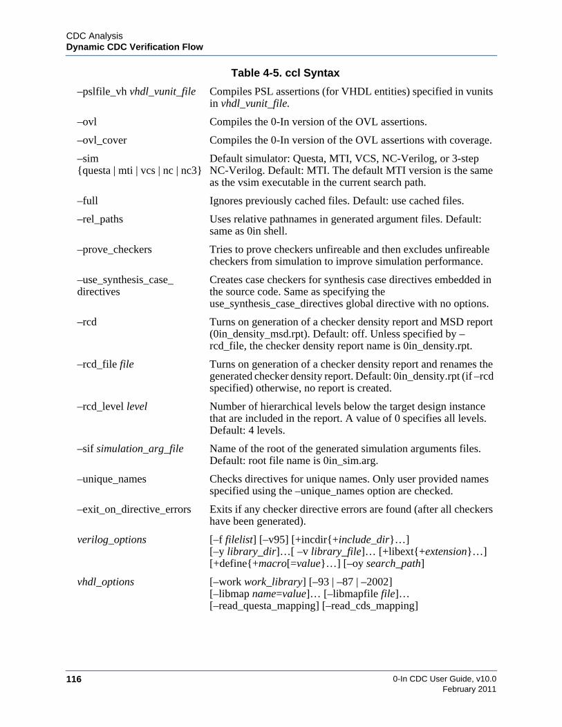
0-In CDC User Guide, v10.0116
CDC AnalysisDynamic CDC Verification Flow
February 2011
–pslfile_vh vhdl_vunit_file Compiles PSL assertions (for VHDL entities) specified in vunitsin vhdl_vunit_file.
–ovl Compiles the 0-In version of the OVL assertions.
–ovl_cover Compiles the 0-In version of the OVL assertions with coverage.
–sim{questa | mti | vcs | nc | nc3}
Default simulator: Questa, MTI, VCS, NC-Verilog, or 3-stepNC-Verilog. Default: MTI. The default MTI version is the sameas the vsim executable in the current search path.
–full Ignores previously cached files. Default: use cached files.
–rel_paths Uses relative pathnames in generated argument files. Default:same as 0in shell.
–prove_checkers Tries to prove checkers unfireable and then excludes unfireablecheckers from simulation to improve simulation performance.
–use_synthesis_case_directives
Creates case checkers for synthesis case directives embedded inthe source code. Same as specifying theuse_synthesis_case_directives global directive with no options.
–rcd Turns on generation of a checker density report and MSD report(0in_density_msd.rpt). Default: off. Unless specified by –rcd_file, the checker density report name is 0in_density.rpt.
–rcd_file file Turns on generation of a checker density report and renames thegenerated checker density report. Default: 0in_density.rpt (if –rcdspecified) otherwise, no report is created.
–rcd_level level Number of hierarchical levels below the target design instancethat are included in the report. A value of 0 specifies all levels.Default: 4 levels.
–sif simulation_arg_file Name of the root of the generated simulation arguments files.Default: root file name is 0in_sim.arg.
–unique_names Checks directives for unique names. Only user provided namesspecified using the –unique_names option are checked.
–exit_on_directive_errors Exits if any checker directive errors are found (after all checkershave been generated).
verilog_options [–f filelist] [–v95] [+incdir{+include_dir}…][–y library_dir]…[ –v library_file]… [+libext{+extension}…][+define{+macro[=value}…] [–oy search_path]
vhdl_options [–work work_library] [–93 | –87 | –2002][–libmap name=value]… [–libmapfile file]…[–read_questa_mapping] [–read_cds_mapping]
Table 4-5. ccl Syntax

CDC AnalysisDynamic CDC Verification Flow
0-In CDC User Guide, v10.0 117February 2011
rtl_options [+skip_modules {+module}…][+skip_syscalls {+systemcall}…][–skip_protected_modules] [–skip_protected_code][–ignore_translate_off]
reporting_options [–wd working_directory][+nowarn{+messageID}…][+error{+messageID}…
compile_options [file…] [–d design] [–prefix hierarchy_prefix][–ctrl checker_control_file]… [–ctrl_list checker_ctrl_file… [–]][–vhctrl vhdl_control_file]… [–G name=value]…[–g name=value]… [–cr report_file]
Table 4-5. ccl Syntax
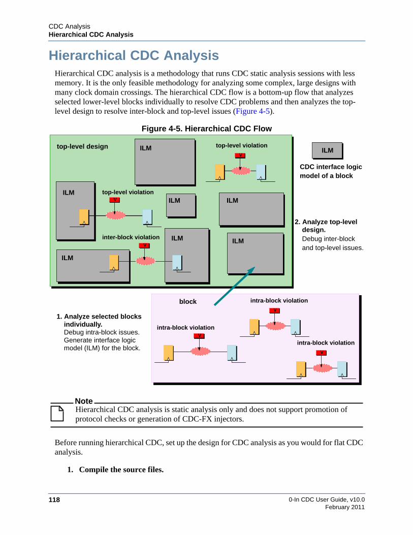
0-In CDC User Guide, v10.0118
CDC AnalysisHierarchical CDC Analysis
February 2011
Hierarchical CDC AnalysisHierarchical CDC analysis is a methodology that runs CDC static analysis sessions with lessmemory. It is the only feasible methodology for analyzing some complex, large designs withmany clock domain crossings. The hierarchical CDC flow is a bottom-up flow that analyzesselected lower-level blocks individually to resolve CDC problems and then analyzes the top-level design to resolve inter-block and top-level issues (Figure 4-5).
Figure 4-5. Hierarchical CDC Flow
NoteHierarchical CDC analysis is static analysis only and does not support promotion ofprotocol checks or generation of CDC-FX injectors.
Before running hierarchical CDC, set up the design for CDC analysis as you would for flat CDCanalysis.
1. Compile the source files.
V
top-level design top-level violation
V
inter-block violation
Vtop-level violation
CDC interface logic
V
block intra-block violation
V
intra-block violation
V
intra-block violation
model of a block
ILM
1. Analyze selected blocksindividually.Debug intra-block issues.Generate interface logic
2. Analyze top-level
Debug inter-blockand top-level issues.
model (ILM) for the block.
ILM
ILM
ILM
ILM
ILM
ILM
ILM
design.

CDC AnalysisHierarchical CDC Analysis
0-In CDC User Guide, v10.0 119February 2011
2. Set up a top-level control file.
• Identify the design clocks (set_cdc_clock).
• Identify the clock domains of the primary ports (set_cdc_port_domain).
• Identify sources of stable signals (set_constant and set_cdc_signal -stable) so CDCanalysis can optimize design logic.
• Identify custom synchronizers (set_cdc_synchronizer) and black-boxmodules/entities (set_black_box).
• Set up any other CDC preferences.
3. Run cdc with the -report_clock option.
For example:
0in> cdc -d top -report_clock -ctrl top_ctrl.v
4. Check for errors and warnings.
Check the CDC logs; fix errors; and resolve warnings. If you change the source code, goto step 1.
5. Check 0in_cdc_design.rpt.
Ensure the clock groups and port domains are identified correctly. If not, go to step 2and fix.
Basic Hierarchical CDC FlowTo run CDC analysis for a particular block, you must specify a hierarchical constraints controlfile for the block. This file identifies the CDC constraints that the design imposes on the blockYou can generate control files for all specified blocks automatically by running CDC analysisof the top-level design in a special block constraints generation mode. The basic hierarchicalCDC flow is a 3-phase process as shown in Figure 4-6.
Phase 1: Generate Block Constraints
In the first phase of the basic hierarchical CDC analysis flow, you generate block constraints forall the hierarchical blocks at once. A block’s CDC constraints are specified as a set of globaldirectives in a Verilog hierarchical constraints module associated with the block, saved as aCDC control file for the block. A hierarchical constraints module for a block has two parts (seeExample 4-1):
• Global CDC preferences
Design-level global directives can apply to the various blocks as well as the design as awhole. For example, set_cdc_preference, set_cdc_fifo_preference,set_cdc_handshake_preference, set_constant_propagation and set_cdc_reconvergence

0-In CDC User Guide, v10.0120
CDC AnalysisHierarchical CDC Analysis
February 2011
can apply globally and can apply to the hierarchical blocks or their sub-blocks (i.e., withthe -module option). Those directives that apply to the block are reproduced in theglobal CDC preferences section so you do not need to taylor the design-levelpreferences to each block.
Figure 4-6. Basic Hierarchical CDC Flow
• Block specifications
Clock domain analysis of the block’s instances determines the block instances’ clocksand clock domains of the block’s ports. These constraints are specified withset_cdc_clock and set_cdc_port_domain directives. Also, set_constant andset_cdc_signal -stable directives are “propagated” to the block instance logic.
Example 4-1. Hierarchical Constraints Control File
module zin_cdc_hier_constraints_ctrl_blk2;
// Block: blk2// Instances: b2// Parameters/Generics: W = 16// Global CDC Preferences// 0in set_cdc_preference -promote_reconvergence// -formal_add_bus_stability -formal_add_recon_stability
Generate Block Constraints
Phase 1
Analyze Top-level Design
Phase 3
Analyze Blocks
Phase 2
cdc . . . -report_constraints blk1 blk2 blk3 . . .
hierarchical constraints files
block CDC interface models
(0in_cdc_hier_constraints_*_ctrl.v)
(0in_hier/*/0in_cache)
cdc . . . -hier_block blk1 \
cdc . . .-hier_block blk2 \
. . .
cdc . . .-hier_block blk3 \
cdc . . . -hier_cache \0in_hier/blk1/0in_cache \0in_hier/blk2/0in_cache \0in_hier/blk3/0in_cache . . .
-ctrl 0in_cdc_hier_constraints_blk1_ctrl.v . . .
-ctrl 0in_cdc_hier_constraints_blk2_ctrl.v . . .
-ctrl 0in_cdc_hier_constraints_blk3_ctrl.v . . .
CDC AnalysisHierarchical CDC Analysis
0-In CDC User Guide, v10.0 121February 2011
// 0in set_cdc_fifo_preference -no_read_sync// 0in set_cdc_handshake_preference -check_mux_recirculation// 0in set_constant_propagation -latch// 0in set_cdc_reconvergence -depth 4 -divergence_depth 3
// 0in set_cdc_clock clk -module blk2// 0in set_cdc_port_domain rst -none -module blk2// 0in set_cdc_port_domain data_in1 -clock clk -module blk2// 0in set_cdc_clock top.clk1 -virtual -module blk2// 0in set_cdc_port_domain data_in -clock top.clk1 -module blk2// 0in set_cdc_port_domain data_out -clock top.clk2 -module blk2
endmodule
Running cdc in the CDC constraints generation mode generates these control files for all of theblock-level analyses:
1. Select hierarchical blocks.
Select the blocks you want to analyze individually. Typically they correspond to designunits handled by individual developers or development teams. Candidates are blockswith many internal CDC boundaries. Since you are trying to reduce the memory used forCDC analysis, you should select blocks that distribute the CDC logic evenly across theblocks.
Block instances do not have to be at the top level of the design. But, block instancescannot have hierarchical references to objects in the top level or to other block instances(and vice versa). That is, when you analyze a hierarchical block in phase 2, all of itshierarchical references must be resolved within the block and when you analyze the toplevel in phase 3, all of its hierarchical references must be resolved to objects not in anyblock analyzed in phase 2.
2. Run cdc with the -report_constraints option.
This option runs CDC constraint generation, reports the clock domain data and quits.The arguments to -report_constraints are the design unit names of the block instances.For example:
0in> cdc -d top -ctrl top_ctrl.v \-report_constraints blk1 blk2 blk1
If the same module/entity is instantiated more than once, CDC constraint generationhandles variations in the top-level connectivity and parameters/generics for the differentinstances.
3. Check results.
a. Fix errors and resolve warnings.
b. Check 0in_cdc_design.rpt and ensure the clock groups and port domains areidentified correctly.
0-In CDC User Guide, v10.0122
CDC AnalysisHierarchical CDC Analysis
February 2011
c. Check the 0in_cdc_hier_constraints_*_ctrl.v files (if desired). For each block,check the design unit name, instance name, parameter/generic values and the globaldirectives.
Phase 2: Analyze Blocks
For block-level CDC analysis, run a CDC analysis session for each block. To speed up analysis,run these sessions on different hosts in parallel. The following steps analyze the blk2 block:
1. Run block-level CDC analysis.
For example:
0in> cdc -d top -od 0in_hier/blk2 \-ctrl 0in_cdc_hier_constraints_blk2_ctrl.v -hier_block blk2
To segregate the block-level analysis from that of the other blocks and from the top-level analysis, the output is directed to a subdirectory of the 0in_hier directory (-od0in_hier/blk2). The block constraints file (0in_cdc_hier_constraints_blk2_ctrl.v) wasgenerated in phase 1. The -hier_block argument identifies the block for the block-levelanalysis.
2. Run the CDC GUI and verify the CDC analysis.
shell prompt> 0in_cdc 0in_hier/blk2/0in_cdc.db
Verify the CDC checks for the block. Violations represent issues within the block. Youcan fix problems with the RTL source code, re-run CDC analysis for the block anditerate. But, changes to the RTL might affect CDC analysis of other blocks or the toplevel design, so use caution. If you do change the source code, you must re-generateblock constraints and re-run block analyses for all hierarchical blocks—to ensure theresults are accurate and complete—before you analyze the top-level design.
Phase 3: Analyze Top-level Design
CautionYou can run top-level CDC analysis only if the RTL of the design and the blocks match.If you change the logic after running block-level analysis, you must re-run the completehierarchical CDC flow. You also need to use the same version of vlog/vcom and 0-Intools for the complete hierarchical CDC flow.
Top-level CDC analysis builds a model of the top design from the CDC interface models for theblocks analyzed in phase 2 and from the remaining design logic.
1. Run top-level CDC analysis.
For example:
0in> cdc -d top -od 0in_hier/top -ctrl top_ctrl.v \

CDC AnalysisHierarchical CDC Analysis
0-In CDC User Guide, v10.0 123February 2011
-hier_cache 0in_hier/blk1/0in_cache \0in_hier/blk2/0in_cache \0in_hier/blk3/0in_cache
The -hier_cache option lists cache directories for the hierarchical blocks. The0in_hier/blk1, 0in_hier/blk2 and 0in_hier/blk3 directories were specified as the outputdirectories (-od dir) during the block-level sessions. The name specified for caches is0in_cache by default. However, if you change the 0in cache directory name (i.e., usingthe -cache option to the 0in shell), the corresponding -hier_cache pathnames mustmatch.
The top-level CDC analysis detects the crossings not covered by the block-level runsand the crossings into the portal boundaries of the hierarchical blocks.
When you run cdc on the top-level design, the cdc command performs consistencychecks. These ensure that the criteria assumed for block-level analyses are consistentwith the logic of the top-level design. If the block-level analyses used constraints filesgenerated by -report_constraints and the design logic did not change, the data should beconsistent. Consistency check violations might occur if logic changes were made afterrunning cdc -report_constraints, or if the constraints file for a block was specifiedmanually. The types of constituency checks are:
• Clocks
• Clocks connected to the block ports are the same between block-level and top-level runs.
• Block-level clock groups match the clock groupings in the top level.
• Constants
• Constants on the block ports are the same between block-level and top-levelruns.
• Port domains
• Port domains of the block ports match between block-level and top-level runs.
• Stable ports
• Stable block ports in the block level must also be marked stable in the top-levelrun.
2. Run the CDC GUI and verify the CDC analysis.
shell prompt> 0in_cdc 0in_hier/top/0in_cdc.db
Check the results for the design. At this point, the whole design is available to the GUIfor debugging. Results from the block-level sessions are merged into the top-levelresults. However within the blocks, only partial netlist information is available (i.e., onlythe level of detail retained in the CDC interface models of the blocks).

0-In CDC User Guide, v10.0124
CDC AnalysisHierarchical CDC Analysis
February 2011
Hierarchical CDC ScriptsIn addition to generating the block CDC constraints, the -report_constraints option of cdccreates two scripts (0in_hier.scr and 0in_hier.Makefile) useful for hierarchical CDC analysis(Figure 4-7). These scripts run the basic hierarchical CDC flow based on the informationsupplied when running cdc in the CDC constraints generation mode. They can be used “as is” orcan be modified to handle advanced flows. The -report_hier_scripts option generates thesescripts without performing constraints generation.
Figure 4-7. -report_constraints Generates Hierarchical CDC Scripts
The scripts are generated so that the output directory specified by the -od 0in shell option(default: current run directory) for the cdc session is specified as the output directory for thefiles generated by the scripts.
0in_hier.scr
The 0in_hier.scr script (see Example 4-2) is a csh script that runs the block-level analyses insequence and then runs the top-level analysis:
shell prompt> 0in_hier.scroutput from block-level sessionsoutput from the top-level session
shell prompt> 0in_cdc 0in_hier/top/0in_cdc.db
Generate Block Constraints
Phase 1
Analyze Blocks
Phase 2
cdc -report_constraints blk1 blk2 blk3 . . .
0in_cdc_hier_blk1_ctrl.v 0in_hier.scr0in_hier.Makefile0in_cdc_hier_blk2_ctrl.v
0in_cdc_hier_blk3_ctrl.v

CDC AnalysisHierarchical CDC Analysis
0-In CDC User Guide, v10.0 125February 2011
Example 4-2. 0in_hier.scr
#!/bin/csh -f##-----------------------------------------------------------------## Hierarchical CDC Script##-----------------------------------------------------------------\rm -fr 0in_hiermkdir 0in_hierset cdc_od = 0in_hierset cdc_hier_cmd = “cdc -d top dut.v”set cdc_top_cmd = “cdc -d top -ctrl top_ctrl.v dut.v”set ZIN = 0in
# Invoke CDC for all the blocks.set fail = 0set fail_mode = ““
# BLOCK LEVEL RUN: blk1$ZIN -od $cdc_od/blk1 -cache 0in_cache -cmd $cdc_hier_cmd -hier \
-ctrl /design/dut/0in_cdc_hier_constraints_blk1_ctrl.v \-hier_block blk1
# Check for failureif ($status != 0) then
if ($fail == 0) thenset fail = 1set fail_mode = blk1:blk1
elseset fail_mode = ($fail_mode blk1:blk1)
endifendif. . .
# TOP-LEVEL RUN: top$ZIN -od ${cdc_od}/top -cmd $cdc_top_cmd \
-hier_cache $cdc_od/sub1/0in_cache \$cdc_od/sub2/0in_cache
# Check for failureif ($status != 0) then
if ($fail == 0) thenset fail = 1set fail_mode = top
elseset fail_mode = ($fail_mode top)
endifendif# Summaryif ($fail == 0) then echo PASSED exit 0else echo FAILED : $fail_mode exit -1endif

0-In CDC User Guide, v10.0126
CDC AnalysisHierarchical CDC Analysis
February 2011
0in_hier.Makefile
The 0in_hier.Makefile script (see Example 4-3) is a Makefile that runs the block-level analysesand the top-level analysis. The make all directive runs these tasks in sequence:
shell prompt> make -f 0in_hier.Makefile alloutput from block-level sessionsoutput from the top-level session
shell prompt> 0in_cdc 0in_hier/top/0in_cdc.db
In addition to the front-to-back flow, the Makefile can be used to run the cdc sessionsindividually, for example:
shell prompt> make -f 0in_hier.Makefile blk1shell prompt> 0in_cdc 0in_hier/blk1/0in_cdc.db
shell prompt> make -f 0in_hier.Makefile blk2shell prompt> 0in_cdc 0in_hier/blk2/0in_cdc.db
shell prompt> make -f 0in_hier.Makefile blk3shell prompt> 0in_cdc 0in_hier/blk3/0in_cdc.db
shell prompt> make -f 0in_hier.Makefile topshell prompt> 0in_cdc 0in_hier/top/0in_cdc.db
The targets of the make commands are the design unit names of the blocks (blk1, blk2 and blk3in this example) and the DUT name (top).
Example 4-3. 0in_hier.Makefile
## Hierarchical CDC Makefile##-----------------------------------------------------CDC_OD = 0in_hierCDC_HIER_CMD = "cdc -d top dut.v"CDC_TOP_CMD = "cdc -d top dut.v"0IN = 0in
all:BLOCKS topBLOCKS:blk1 blk2 blk3
# BLOCK-LEVEL RUN: blk1blk1: rm -rf $(CDC_OD)/blk1
$(0IN) $(DEBUG) -od $(CDC_OD)/blk1 -cache 0in_cache \-cmd $(CDC_HIER_CMD) -hier \-ctrl /design/dut/0in_cdc_hier_constraints_blk1_ctrl.v \-hier_block blk1
# BLOCK-LEVEL RUN: blk2blk2: rm -rf $(CDC_OD)/blk2
$(0IN) $(DEBUG) -od $(CDC_OD)/blk2 -cache 0in_cache \-cmd $(CDC_HIER_CMD) -hier \-ctrl /design/dut/0in_cdc_hier_constraints_blk2_ctrl.v \-hier_block blk2

CDC AnalysisHierarchical CDC Analysis
0-In CDC User Guide, v10.0 127February 2011
# BLOCK-LEVEL RUN: blk3blk3: rm -rf $(CDC_OD)/blk3
$(0IN) $(DEBUG) -od $(CDC_OD)/blk3 -cache 0in_cache \-cmd $(CDC_HIER_CMD) -hier \-ctrl /design/dut/0in_cdc_hier_constraints_blk3_ctrl.v \-hier_block blk3
# TOP-LEVEL RUN: toptop: rm -rf $(CDC_OD)/top
$(0IN) $(DEBUG) -od $(CDC_OD)/top -cmd $(CDC_TOP_CMD)-ctrl top_ctrl.v \-hier_cache \
$(CDC_OD)/blk1/0in_cache \$(CDC_OD)/blk2/0in_cache \$(CDC_OD)/blk3/0in_cache
WaiversWaivers are instances of clock-domain crossing schemes that are “waived” from reporting.Waiving scheme instances eliminate the “noise” created by identifying all of the CDC issuesfound in the design. By waiving a particular instance of a CDC scheme, you are indicating theinstance is OK (at least for the time being). For example, you might waive an instance of amissing synchronizer because you know the crossing has no synchronization issues. Each timeyou run CDC analysis with waivers identified, only relevant CDC issues are shown in the GUICDC Checks window by default, so you do not waste time studying CDC issues that are notmeaningful.
For example, before performing hierarchical CDC analysis, you typically run flat CDC analysison the various blocks as they are developed. When you view the results and debug issues, youtypically mark crossings and issues to be waived. These waivers are saved as a CDC control filefrom the GUI (sometimes called a waiver file). You can specify this file during later CDCanalysis sessions, to filter out issues already considered.
In a similar way, you can incorporate waivers into the hierarchical CDC flows.
1. After running block-level analysis of a block, run the CDC GUI:
shell prompt> make -f 0in_hier.Makefile blk1shell prompt> 0in_cdc 0in_hier/blk1/0in_cdc.db
2. Import the waivers file for the block if you have one: File >Import >Directive File.
Previously-created waivers from the block development stage can be applied to thehierarchical CDC block-level results.
3. Check the existing specifications for each waived instance of a CDC scheme and addadditional waivers as needed.
Since you eventually want to roll the waivers up into top-level analysis, you must ensurethe waivers are properly formed for this purpose. To waive a CDC scheme instance,
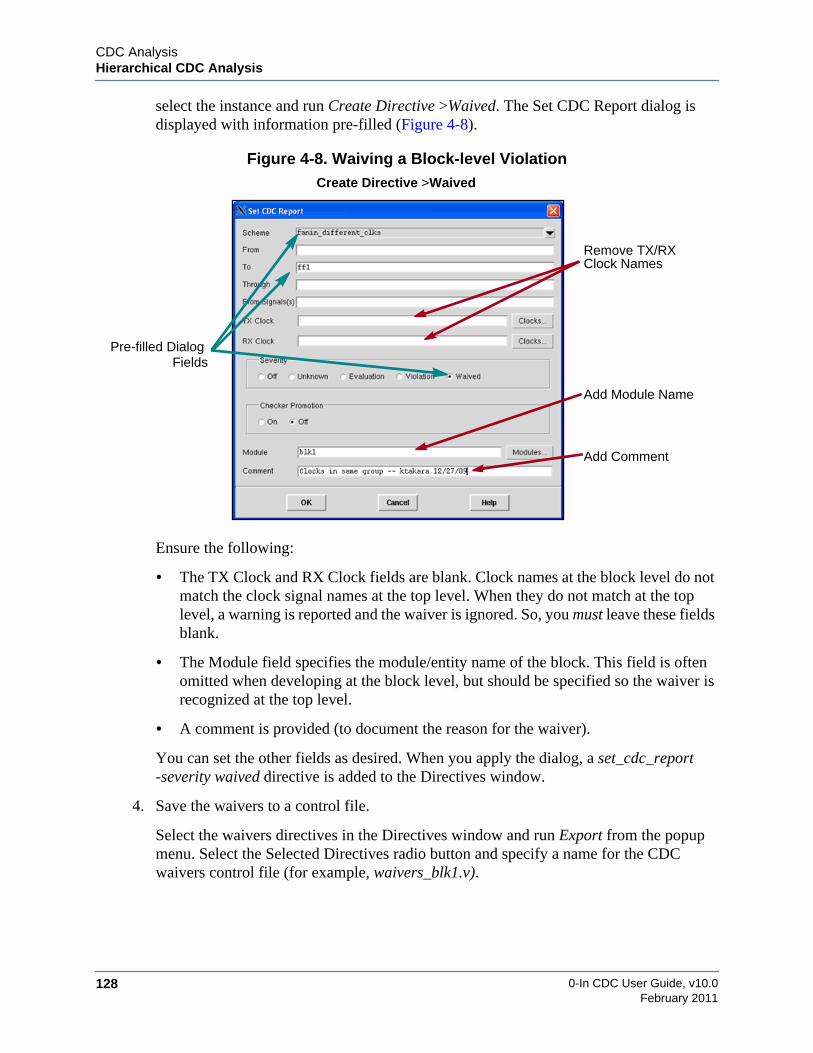
0-In CDC User Guide, v10.0128
CDC AnalysisHierarchical CDC Analysis
February 2011
select the instance and run Create Directive >Waived. The Set CDC Report dialog isdisplayed with information pre-filled (Figure 4-8).
Figure 4-8. Waiving a Block-level Violation
Ensure the following:
• The TX Clock and RX Clock fields are blank. Clock names at the block level do notmatch the clock signal names at the top level. When they do not match at the toplevel, a warning is reported and the waiver is ignored. So, you must leave these fieldsblank.
• The Module field specifies the module/entity name of the block. This field is oftenomitted when developing at the block level, but should be specified so the waiver isrecognized at the top level.
• A comment is provided (to document the reason for the waiver).
You can set the other fields as desired. When you apply the dialog, a set_cdc_report-severity waived directive is added to the Directives window.
4. Save the waivers to a control file.
Select the waivers directives in the Directives window and run Export from the popupmenu. Select the Selected Directives radio button and specify a name for the CDCwaivers control file (for example, waivers_blk1.v).
Pre-filled DialogFields
Remove TX/RXClock Names
Add Module Name
Add Comment
Create Directive >Waived
CDC AnalysisHierarchical CDC Analysis
0-In CDC User Guide, v10.0 129February 2011
5. Specify the waivers control files for the blocks during top-level CDC control filegeneration:
0in> cdc -d top -ctrl top_ctrl.v \-report_constraints blk1 blk2 blk3 \-ctrl waivers_blk1.v -ctrl waivers_blk2.v -ctrl waivers_blk3.v
Variations on the Hierarchical CDC FlowWith the basic hierarchical CDC flow, you propagate CDC constraints from the top level to theblocks, run block-level analyses and then analyze the top-level design. When you load theresults into the CDC GUI, all the CDC checks from the block-level and top-level runs aremerged into the GUI session. Virtually all of the design’s internal logic is available fordebugging operations. So, the basic hierarchical CDC flow produces results and provides adebug environment just as if you ran the design through flat CDC analysis. In addition:
• By “carving up” the analysis problem, memory needed for overall analysis issignificantly reduced.
• Since you can run the various block-level sessions in parallel, end-to-end analysis timeis significantly reduced.
The basic hierarchical CDC flow is based on certain assumptions.
• All instances of each hierarchical CDC block have the same clock domains, portdomains and parameter/generics settings.
• All hierarchical CDC blocks are suitable for block-level CDC analysis.
• You have a top-level design you can use to generate the CDC block constraints.
You can work around these assumptions as described in the following sections.
Heterogeneous Instances of BlocksHomogeneous instances of a module/entity are instances that have the same configuration (i.e.the same parameters/generics and connectivity). Heterogeneous instances of a module/entityare instances that have different configurations. With the basic hierarchical CDC flow, allinstances of each hierarchical CDC block are assumed to be homogeneous. A variation of thebasic hierarchical CDC flow is used to analyze designs whose hierarchical CDC blocks haveheterogeneous instances.
When you generate block constraints (phase 1), a hierarchical control file is generated for eachspecified hierarchical CDC block. For example:
0in_cdc_hier_constraints_blk1_ctrl.v0in_cdc_hier_constraints_blk2_ctrl.v0in_cdc_hier_constraints_blk3_ctrl.v

0-In CDC User Guide, v10.0130
CDC AnalysisHierarchical CDC Analysis
February 2011
In this example, all instances of blk1 are homogeneous, all instances of blk2 are homogeneous,and so on. But, if a block has heterogeneous instances, a hierarchical control file is generated foreach homogeneous group of instances of the block. So, if blk1 has two sets of instances thathave different configurations, two hierarchical control files are generated:
0in_cdc_hier_constraints_blk1_0_ctrl.v0in_cdc_hier_constraints_blk1_1_ctrl.v
During block-level analysis, each of these instance groups must be analyzed separately. Forexample:
0in> cdc -d top -od 0in_hier/blk1_0 \-ctrl 0in_cdc_hier_constraints_blk1_0_ctrl.v \-hier_instance top.U10in> cdc -d top -od 0in_hier/blk1_1 \-ctrl 0in_cdc_hier_constraints_blk1_1_ctrl.v \-hier_instance top.U3
In this example, blk1 has two homogeneous groups of instances: (top.U1 top.U1) and (top.U3).Instead of specifying the blk1 block with the -hier_block module argument, you specify thehomogeneous instances with a -hier_instance instances argument. In this example, block-levelanalyses of blk1 generate two CDC interface models for use in the top-level analysis:
0in_hier/blk1_0/0in_cache0in_hier/blk1_1/0in_cache
Tip: The 0in_hier.scr and 0in_hier.Makefile scripts also work for heterogeneousinstances of blocks. For example, make -f 0in_hier.Makefile blk1_0.
When hierarchical blocks are present, 0in_cdc_design.rpt identifies them:
General Design Information==========================Number of Black Boxes = 0Number of Registers = 145Number of Latches = 0Number of RAMs = 2Number of CFM Hierarchical Blocks = 1Number of ILM Hierarchical Blocks = 1Number of CDC bits = 82
Detail Design Information=========================CFM Hierarchical Blocks:------------------------ U1 ( blk1 )
ILM Hierarchical Blocks:------------------------ U2 ( blk2 )

CDC AnalysisHierarchical CDC Analysis
0-In CDC User Guide, v10.0 131February 2011
Control File ModelsThe basic hierarchical CDC flow uses CDC interface models generated by block-level CDCanalyses (stored in cache directories, for example: 0in_hier/*/0in_cache). Sometimes, youcannot generate a CDC interface model for a block (for example, because it has unsynthesizableconstructs). Sometimes you can generate an interface model but it is too large. Sometimes yousimply want to run a quicker top-level analysis as a form of sanity check. Some block netlistscan be eliminated from analysis. In these cases you can swap in a simplified model called acontrol file model (CFM) for the top-level analysis session (Figure 4-9).
To generate a control file model during block-level analysis of a block, add the followinghierarchical CDC preference to the block-level control file:
// 0in set_cdc_hier_preference -ctrl_file_models
CDC analysis for the block generates both an ILM model and a CFM model (named0in_cdc_hier_*_ctrl.v). You also can add the directive to the top-level control file in order topropagate the directive to the block-level analyses via the hierarchical control files (during thereport constraints step).
Figure 4-9. Top-level CDC Analysis with CFMs
For the blocks that you want to use the control file models, specify the corresponding generatedcontrol files with the -hier_ctrl_file_model option. For example:
0in> cdc -d top -od 0in_hier/top -ctrl top_ctrl.v \-hier_cache 0in_hier/blk1/0in_cache \
0in_hier/blk2/0in_cache \-hier_ctrl_file_model blk3 0in_cdc_hier_blk3_ctrl.v
V
top-level design top-level violation
V
inter-block violation
interfacelogic model
control filemodel
Vtop-level violation
analyzed blockspreviously
ILM
ILM
ILM
ILM ILM
ILMCFMCFM
CFM

0-In CDC User Guide, v10.0132
CDC AnalysisHierarchical CDC Analysis
February 2011
Here, blk1 and blk2 are modeled as ILMs and blk3 is modeled as a CFM. Never specify both anILM and a CFM for the same block. Table 4-6 compares the ILM and CFM models andTable 4-7 shows the limitations of the control file models.
Table 4-6. ILMs vs. CFMsFeature Interface Logic Model Control File Modeldata structure Internal interface logic model
saved in a block-level cache.0-In format control file.
efficacy Results are equivalent tostandard (flat) CDC analysis.
Some CDC schemes might bemissed.
user control User can limit the depth of CDCanalysis.
User can edit the control file.
granularity Blocks can be modules/entitiesand instances.
Blocks can be modules/entities,but not instances.
GUI Block logic schematicsavailable.
Block logic schematics notavailable.
Table 4-7. Control File Model Limitations
Feature Limitation
multiple constraints Separate constraints for different instances of the block are notsupported.
non-default parameters Separate parameter sets for different instances of the block are notsupported. CDC analysis uses the default parameter values for theblock.
reconvergence Reconvergence violations starting from or ending in the block arenot reported.
input port fanout Fanout data in the block is discarded, so CDC reports only onecrossing to an input port of the block when multiple crossingsthrough the port fan out to multiple receivers.
promoted checkers Number of promoted CDC protocol and CDC-FX checkers candiffer between hierarchical and standard analysis.
bused, internal and virtualclocks
Ignored in generated control file models and during block-levelanalysis.
complex schemes Multibit (data) synchronizers are not supported. DMUX is theonly complex (nested) scheme detected. However, basic schemessuch as control and bit synchronizers are supported.
bitwise port domains Not supported. SystemVerilog structs with different port domainsfor different fields are marked as -nosync ports.
inout ports Not supported.
set_constant Slices and bits in the block are not supported for set_constant.
combo fanout Combo fanout can degrade constraints of ports which havemajority of sequential fanouts. Workaround is to set -ignore orport domain on the combo fanout port at block level.
CDC AnalysisModal CDC Analysis
0-In CDC User Guide, v10.0 133February 2011
Modal CDC AnalysisThe customer’s design can have several modes of operation. Following are several reasons forhaving multiple modes:
• Testing — in this mode, sequential elements are chained together.
• Power optimization — idle design blocks can be disabled, and clocks can be gated.
• Handles configurable designs — design might be targeted for multiple customers.
Running CDC analysis on these designs results in a large number of CDC violations. Users areonly interested in a subset of the violations that are relevant to the modes their designs areintended to operate in. In addition, many users (particularly verification engineers) might not beaware of the operating modes a design could operate in. A feature to automatically infer all theoperating modes and let the user select the ones their design can operate in helps address thisissue.
Modal analysis enables the user to specify the operating modes, or infer all of the modes, orallows the user to select the set that is of interest. CDC analysis only generates violations for themodes selected by the user.
Modal analysis has the following features:
• Automatically infer clock domain modes, with capabilities for user specification ofmodes.
• Allows the user to spawn multiple CDC runs to analyze the circuit in each mode.
• Debug the results of all modes through a single data base.
The modes are inferred based on the clock multiplexing in the design. For example, for a designwith three clock domains (A, B, and C), if clock domain B can be synchronized to A with aMUX and the clock domain C can be synchronized to A with a MUX, each with separatecontrol signals as shown in Figure 4-10, then there are three possible modes that are of interestfor CDC analysis as follows:
1. All asynchronous.
2. A and B grouped into one domain, C a separate domain.
3. A and C grouped into one domain, B a separate domain.
The fourth mode of operation, when all clocks are grouped into one domain (driven by CLKA),is not of interest to CDC analysis.

0-In CDC User Guide, v10.0134
CDC AnalysisModal CDC Analysis
February 2011
Figure 4-10. Modes are Inferred Based on the Clock Multiplexing
To perform the automatic recognition of clock modes, add the -report_modes option to theCDC command line. With this option, the 0in_cdc_mode_control.v file is automatically created.This file contains the definition of the inferred modes. The 0in_mode.scr shell script is thenexecuted to spawn multiple CDC runs to analyze each mode.
The mode control file can be edited to eliminate any modes that are not of interest by adding the-ignore option to the corresponding set_mode global directive in this file. Then CDC can bererun with the modified mode control file as an input control file (using the -ctrl option) toupdate the run script.
The results of all modes can be analyzed together using the CDC GUI. Invoke the CDC GUIwith the following command:
0in_cdc 0in_cdc.db
Use ModelModal analysis has two approaches as follows:
• With user-specified modes and inferred modes
• With inferred modes only
The basic use model for both approaches is identical. The difference is in the way analysis isdone and reports are generated. These differences are highlighted throughout the flow. Runningmodal analysis is a four step process as follows:
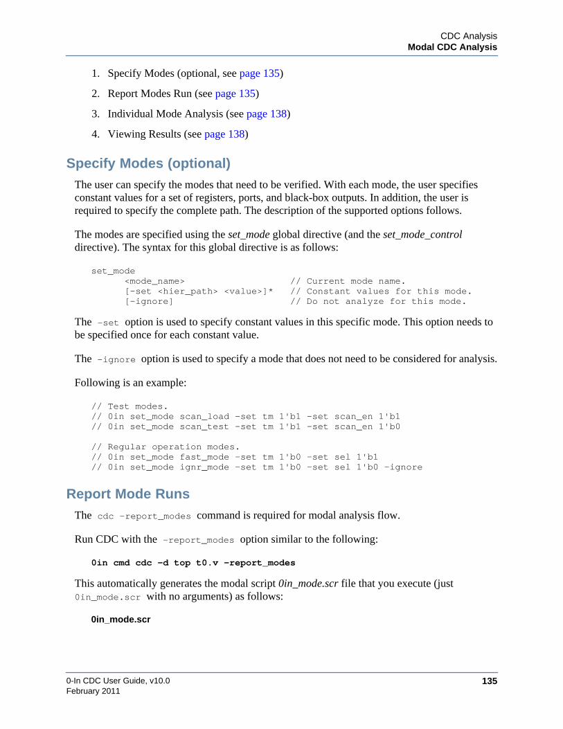
CDC AnalysisModal CDC Analysis
0-In CDC User Guide, v10.0 135February 2011
1. Specify Modes (optional, see page 135)
2. Report Modes Run (see page 135)
3. Individual Mode Analysis (see page 138)
4. Viewing Results (see page 138)
Specify Modes (optional)The user can specify the modes that need to be verified. With each mode, the user specifiesconstant values for a set of registers, ports, and black-box outputs. In addition, the user isrequired to specify the complete path. The description of the supported options follows.
The modes are specified using the set_mode global directive (and the set_mode_controldirective). The syntax for this global directive is as follows:
set_mode<mode_name> // Current mode name.[-set <hier_path> <value>]* // Constant values for this mode.[-ignore] // Do not analyze for this mode.
The -set option is used to specify constant values in this specific mode. This option needs tobe specified once for each constant value.
The -ignore option is used to specify a mode that does not need to be considered for analysis.
Following is an example:
// Test modes.// 0in set_mode scan_load -set tm 1'b1 -set scan_en 1'b1// 0in set_mode scan_test -set tm 1'b1 -set scan_en 1'b0
// Regular operation modes.// 0in set_mode fast_mode -set tm 1'b0 -set sel 1'b1// 0in set_mode ignr_mode -set tm 1'b0 -set sel 1'b0 -ignore
Report Mode RunsThe cdc -report_modes command is required for modal analysis flow.
Run CDC with the -report_modes option similar to the following:
0in cmd cdc -d top t0.v -report_modes
This automatically generates the modal script 0in_mode.scr file that you execute (just0in_mode.scr with no arguments) as follows:
0in_mode.scr
0-In CDC User Guide, v10.0136
CDC AnalysisModal CDC Analysis
February 2011
This runs CDC multiple times (one per mode) and creates all of the database files (.db) for eachmode.
For both approaches (user-specified and inferred), the 0in_mode.scr script file is generated (seepage 145). This script contains the steps to run individual mode analysis.
In the presence of user modes, this script runs the user-specified modes only. If the user wishesto analyze any of the missing modes, then the user needs to run this step again with an updatedcontrol file.
If no user modes are specified, then CDC infers all the operating modes. A control file named0in_cdc_mode_ctrl.v (see page 144) is automatically generated with directives specifying allthe inferred modes. Details of all the inferred modes are included in the CDC design0in_cdc_design.rpt report file (see page 144).
If the user modes are specified, then mode inferencing still occurs. The inferred modes arecompared to the user modes to identify any missing or incomplete modes. All errors identifiedin the user specified modes are reported in the 0in_cdc_design.rpt report file (see page 144). Acontrol file named 0in_cdc_mode_ctrl.v (see page 144) is automatically generated withset_mode global directives for incomplete user modes and inferred modes not specified by theuser.
Mode Verification and Coverage ReportingMode verification analyzes user-specified modes for completeness and coverage with respect tothe modes inferred. Appropriate warning messages are generated to report the user modes thatare missing, ignored, incomplete, OK, and duplicate when the cdc -report_option isspecified.
The messages in the modal summary table below have the following meanings:
• Missing mode — This is an inferred mode. For every missing mode, a [hdl-119]message is generated. A set_mode global directive is generated for this inferred modein the 0in_cdc_mode_ctrl.v file.
• Ignored mode — This user mode is ignored for modal analysis. This is specified by theuser with the -ignore option.
• Incomplete mode — This user mode is partially specified and needs additionalconstants. For each missing constant inferred by the tool, a [hdl-125] warning messageis issued. A set_mode global directive is generated for the corresponding completemode in the 0in_cdc_mode_ctrl.v file.
• OK — This user mode is complete (verified). The user mode may contain additionalsignals that were not inferred. These signals are marked as undetected in the modeinformation table. The [hdl-124] information messages are issued for each undetectedsignal.

CDC AnalysisModal CDC Analysis
0-In CDC User Guide, v10.0 137February 2011
• Duplicate mode — This user mode is a duplicate of another user-specified mode orincomplete mode. A [hdl-118] warning message is issued for every duplicate mode.
The Modal summary and information tables shown below are printed in the 0in_cdc_design.rptfile when the cdc -report_modes option is specified.
Modes=====
--------------------------------------------------------------Mode Type Message--------------------------------------------------------------cdc_mode_0 0-In CDC Missing modemode2 User Ignored modemode3 User Incomplete mode(missing constant)mode4 User OKmode5 User OKmode6 User Duplicate mode(mode4)--------------------------------------------------------------
User Modes=========Constants in mode2 (Ignored)----------------------------------------------------Signal Value Type----------------------------------------------------sel1 1'b0 Usersel2 1'b0 User----------------------------------------------------
Constants in mode3 (Incomplete)----------------------------------------------------Signal Value Type----------------------------------------------------sel1 1'b0 Usersel2 1'b1 Usersel3 1'b1 0-In CDC----------------------------------------------------
Constants in mode4----------------------------------------------------Signal Value Type----------------------------------------------------sel4[3:2] 2'b10 Usersel5 3'b110 User----------------------------------------------------
Constants in mode5----------------------------------------------------Signal Value Type----------------------------------------------------sel1 1'b1 Usersel2 1'b0 User

0-In CDC User Guide, v10.0138
CDC AnalysisModal CDC Analysis
February 2011
sel5 3'b101 User (Undetected)----------------------------------------------------
Constants in mode6 (Duplicate)----------------------------------------------------Signal Value Type----------------------------------------------------sel4[3:2] 2'b10 Usersel5 3'b110 User----------------------------------------------------
Inferred Modes===============
Constants in cdc_mode_0 (Missing)----------------------------------------------------Signal Value----------------------------------------------------sel1 1'b1sel2 1'b0sel3 1'b1----------------------------------------------------
Individual Mode AnalysisThe user is required to execute the 0in_mode.scr file manually. This step has the longestruntime. With minimal modifications, the generated script can be run using LSF, which cansignificantly reduce runtimes for large designs. The run command is as follows:
0in_mode.scr
At this point, the user can observe the modes inferred by CDC as well as the modes specified bythe user, even though the CDC run is incomplete (see “Viewing Incomplete CDC Runs” onpage 146).
The user might be interested in verifying their clock tree first before running CDC analysis. Inthis case, the cdc -report_clock option can be used along with report modes. After runningall of the steps, the user can view clock trees for all the modes in the CDC GUI (see “ViewingIncomplete CDC Runs” on page 146).
Viewing ResultsThe results can be viewed using the CDC GUI as follows:
0in_cdc 0in_cdc.db
This command invokes the CDC GUI in the modal state as shown in Figure 4-11 on page 139.
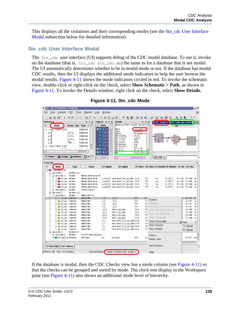
CDC AnalysisModal CDC Analysis
0-In CDC User Guide, v10.0 139February 2011
This displays all the violations and their corresponding modes (see the 0in_cdc User InterfaceModal subsection below for detailed information).
0in_cdc User Interface Modal
The 0in_cdc user interface (UI) supports debug of the CDC modal database. To use it, invokeon the database (that is, 0in_cdc 0in_cdc.db) the same as for a database that is not modal.The UI automatically determines whether to be in modal mode or not. If the database has modalCDC results, then the UI displays the additional mode indicators to help the user browse themodal results. Figure 4-11 shows the mode indicators circled in red. To invoke the schematicview, double-click or right-click on the check, select Show Schematic > Path, as shown inFigure 4-11. To invoke the Details window, right click on the check, select Show Details.
Figure 4-11. 0in_cdc Mode
If the database is modal, then the CDC Checks view has a mode column (see Figure 4-11) sothat the checks can be grouped and sorted by mode. The clock tree display in the Workspacepane (see Figure 4-11) also shows an additional mode level of hierarchy.

0-In CDC User Guide, v10.0140
CDC AnalysisModal CDC Analysis
February 2011
Note that the Mode column in the Transcript window can be moved. This causes the display toreorganize the hierarchy, with Mode as the first level of sorting. Place the cursor on the Modebar, then drag to the desired location as shown in Figure 4-12.
Figure 4-12. Moving the Mode Location
The filters feature can be used to change the default maximum hierarchy displayed. To do this,right-click on a signal and select Filters as shown in Figure 4-13. This invokes the EditPreferences window as shown in Figure 4-14. Change the Maximum Hierarchy Displayednumber as desired. In this example, the number is changed from 3 to 0.
Figure 4-13. Filter

CDC AnalysisModal CDC Analysis
0-In CDC User Guide, v10.0 141February 2011
Figure 4-14. Filter Hierarchy Displayed
Because any schematic path displayed from the CDC Checks view is from a specific CDCmodal run, the schematic always retains its mode so that incremental exploring of thatschematic colors itself as per that mode as shown in Figure 4-11 on page 139. The mode for theschematic path is displayed in the schematic’s title. In addition, the Path ID signal is displayedin the schematic title and in the Details pane, which is multi_bits_68424 for this example(circled in green in Figure 4-11 on page 139).
Note that the bubble help not only displays the usual clock group for a signal, but also the modefor that clock tree as shown in Figure 4-15.

0-In CDC User Guide, v10.0142
CDC AnalysisModal CDC Analysis
February 2011
Figure 4-15. Mode for the Clock Tree
Clock Color as the Mode Context Changes
Any non-CDC path schematics as well as HDL source views update their clock coloring as themode “context” changes. The user can change the mode context by selecting the mode or asignal in the mode tree from within the clock tree view. The current mode is displayed in thetitle bar and the footer.
Figure 4-16 and Figure 4-17 show the color changes as the mode context changes. Note alsothat the Details window reflects the port constraint settings for the current mode selected. Go tothe Workspace window, select Design, then double-click to select an Instance (modr(6) is usedin this example). Then go to the Clocks tab and select a clock in the Mode window(cdc_mode_0 (4) is selected). View the color mode context scheme in Figure 4-16.

CDC AnalysisModal CDC Analysis
0-In CDC User Guide, v10.0 143February 2011
Figure 4-16. Clock Coloring Mode
Now select cdc_mode_1 (5) and observe the signals change color as shown in Figure 4-17.
Figure 4-17. Color Change as the Mode Context Changes

0-In CDC User Guide, v10.0144
CDC AnalysisModal CDC Analysis
February 2011
Examples
0in_cdc_mode_ctrl.v File
An example of the automatically generated mode control file (0in_cdc_mode_ctrl.v) isshown below:
module zin_cdc_mode_ctrl_top;
// Mode: cdc_mode_0// Clock: TRK/* 0in set_mode cdc_mode_0
-set TCS 1'b1*/// Mode: cdc_mode_1// Clocks:// CLK0// RCLK[0]/* 0in set_mode cdc_mode_1
-set TCS 1'b0-set I5[1:0] 2'b0
*/// Mode: cdc_mode_2// Clocks:// CLK0// RCLK[1]/* 0in set_mode cdc_mode_2
-set TCS 1'b0-set I5[1:0] 2'b1
*/endmodule
0in_cdc_design.rpt File
A sample mode coverage report file (generated in 0in_cdc_design.rpt) is shown below:
Mode information================
--------------------------------------------Mode Type Information--------------------------------------------cdc_mode_0 0-In CDC Inferred modecdc_mode_1 0-In CDC Inferred modecdc_mode_2 0-In CDC Inferred mode--------------------------------------------
User Modes==========
None
Inferred Modes==============
Constants in cdc_mode_0

CDC AnalysisModal CDC Analysis
0-In CDC User Guide, v10.0 145February 2011
-------------------------------------------Signal Value-------------------------------------------TCS 1'b1-------------------------------------------
Constants in cdc_mode_1-------------------------------------------Signal Value-------------------------------------------TCS 1'b0I5[1:0] 2'b00-------------------------------------------
Constants in cdc_mode_2-------------------------------------------Signal Value-------------------------------------------TCS 1'b0I5[1:0] 2'b01-------------------------------------------
0in_mode.scr File
A sample automatically generated mode script file (0in_mode.scr) is shown below:
#!/bin/csh -f
\rm -fr /modal/0in_modemkdir /modal/0in_modeset cdc_od = /modal/0in_modeset cdc_cmd = "cdc -d top t0.v"
# Invoke CDC for all the modes.set fail = 0set fail_mode = ""
foreach cdc_mode (cdc_mode_0 cdc_mode_1 cdc_mode_2)
# Run CDC for $cdc_mode0in -od ${cdc_od}/$cdc_mode \
-cmd $cdc_cmd \-ctrl 0in_cdc_mode_ctrl.v \-mode $cdc_mode
# Check for failuresif ($status != 0) then
if ($fail == 0) thenset fail = 1set fail_mode = $cdc_mode
elseset fail_mode = ($fail_mode $cdc_mode)
endifendif
end

0-In CDC User Guide, v10.0146
CDC AnalysisModal CDC Analysis
February 2011
# Cleanupif ($fail == 0) then
echo PASSEDexit 0
elseecho FAILED : $fail_modeexit -1
endif
Viewing Incomplete CDC RunsUp to this point, only completed CDC runs for each mode with complete database results foreach mode have been described.
The user can run modal with the -report_modes option that allows the user to observe modesinferred by CDC as well as the modes specified by the user. In a situation where the UI does nothave completed modal results, the UI displays the modes in the clock view; however, the modesdo not have clock tree information to display unless that mode has successfully completed andthe database for it exists.
There are no CDC checks displayed for an incomplete mode. A default clock tree is displayedfor the user to explore.
Run CDC with -report_modes option to review the clock tree and the possible set of modesfor Modal Analysis.
The ability to view modal results that are still in the process of completing is useful if the designis very large and takes a long time to run CDC for all modes. In addition, the user can viewclock groups for each modal run and modify them accordingly.
Following are the steps to review the clock tree for each modal before the CDC run is complete:
1. Run CDC using the -report_modes option. For example,
cdc -d top t0.v -effort unlimited -cr t0.cdc.rpt -report_modes
This automatically generates the 0in_mode.scr file, which contains the source code togenerate the modes. In addition, the 0in_mode directory is automatically generated.However, at this time the directory is empty because the 0in_mode.scr file that generatesthe reports for each modal has not been run.
2. Invoke the CDC GUI with the following command:
0in_cdc 0in_cdc.db &
This command invokes the CDC GUI as shown in Figure 4-18 with the Clock tabselected. Notice in the Workspace window that the modes are not loaded.

CDC AnalysisModal CDC Analysis
0-In CDC User Guide, v10.0 147February 2011
Figure 4-18. Modes Have No Clock Tree Information
3. Generate the reports for each modal run as follows:
0in_mode.scr
Refer to “0in_mode.scr File” on page 145 for detailed information.
While this command continues to run, the user can review the clock tree as follows (seeFigure 4-19):
File > Reload > Database
Figure 4-19. Reload Database

0-In CDC User Guide, v10.0148
CDC AnalysisModal CDC Analysis
February 2011
Figure 4-20 shows cdc_mode_0 and cdc_mode_1 are now loaded. However,cdc_mode_2 has not completed running and is not loaded. As the design continues torun, the user can continue to select File > Reload > Database to load as theycomplete running.
Figure 4-20. Some Modes Have Clock Tree Information
CDC AnalysisCDC Analysis of FPGAs
0-In CDC User Guide, v10.0 149February 2011
CDC Analysis of FPGAsCDC analysis of an FPGA design requires special handling. The standard FPGA sourcelibraries are designed for simulation and in particular, they are not completely synthesizable.Synthesizable libraries are needed because CDC analysis (unlike simulation) is based on anetlist of the design. Building a netlist requires synthesizable code for compiling the design andfor compiling the FPGA source libraries (see “Compiling FPGA Source Libraries” on page 63).
0-In distribution software comes with synthesizable versions of the unisim/simprim Xilinx andthe Altera source libraries in $HOME_0IN/share/fpga_libs.
Phase 1: Compiling the FPGA Source LibrariesIf you have compiled your FPGA source libraries already for Questa simulation, you can usethem for CDC analysis if:
• The libraries’ RTL is synthesizable VHDL, Verilog or SystemVerilog code.
• The libraries were compiled using the versions of Questa vcom/vlog commands thatmatch those shipped with the 0-In distribution software.
If these statements are true, skip to Phase 2. If not, compile the FPGA source libraries intoresource libraries. First create a directory to hold the compiled FPGA resource libraries:
prompt> mkdir 0in_libs
Then, set up and compile the FPGA source libraries as illustrated in the following examples. IfFPGA library elements are instantiated in VHDL code, you must compile a resource library forthat. The logical library name for this library has no _ver suffix. If FPGA library elements areinstantiated in Verilog code, you must compile a resource library for that. The logical libraryname for this library has a _ver suffix.
Xilinx• unisim
Used for library elements instantiated in VHDL. Compile the VHDL files containing thecomponent and package declarations from the standard Xilinx simulation library. Thencompile the synthesizable Verilog models of the library. The vlog -convertallparamsoption is needed to convert the Verilog parameters to match the generics types in theVHDL component definitions.
vlib 0in_libs/unisimvmap unisim 0in_libs/unisimvcom -work unisim $XILINX/vhdl/src/unisims/unisim_VCOMP.vhdvcom -work unisim $XILINX/vhdl/src/unisims/unisim_VPKG.vhdvlog -work unisim -convertallparams \
$HOME_0IN/share/fpga_libs/Xilinx/ISE/xeclib/unisims/*.v

0-In CDC User Guide, v10.0150
CDC AnalysisCDC Analysis of FPGAs
February 2011
• unisims_ver
Used for library elements instantiated in Verilog. Compile the synthesizable Verilogmodels of the Xilinx library.
vlib 0in_libs/unisimvmap unisims_ver 0in_libs/unisims_vervlog -work unisims_ver \
$HOME_0IN/share/fpga_libs/Xilinx/ISE/xeclib/unisims/*.v
• simprim
Used for library elements instantiated in VHDL. Compile the VHDL files containing thecomponent and package declarations from the standard Xilinx simulation library. Thencompile the synthesizable Verilog models of the library. The vlog -convertallparamsoption is needed to convert the Verilog parameters to match the generics types in theVHDL component definitions.
vlib 0in_libs/simprimvmap simprim 0in_libs/simprimvcom -work simprim $XILINX/vhdl/src/simprims/simprim_Vcomponents.vhdvcom -work simprim $XILINX/vhdl/src/simprims/simprim_Vpackage.vhdvlog -work simprim -convertallparams \
$HOME_0IN/share/fpga_libs/Xilinx/ISE/xeclib/simprims/*.v
• simprims_ver
Used for library elements instantiated in Verilog. Compile the synthesizable Verilogmodels of the Xilinx library.
vlib 0in_libs/simprimvmap simprims_ver 0in_libs/simprims_vervlog -work simprims_ver \
$HOME_0IN/share/fpga_libs/Xilinx/ISE/xeclib/simprims/*.v
• XilinxCoreLib
Used for library elements instantiated in VHDL. Compile the VHDL simulation libraryfiles. The XilinxCoreLib_vhdl_analyze_order filelist specifies the synthesizable files inthe correct compilation order.
vlib 0in_libs/XilinxCoreLibvmap XilinxCoreLib 0in_libs/XilinxCoreLibvcom -work XilinxCoreLib -f XilinxCoreLib_vhdl_analyze_order
• XilinxCoreLib_ver
Used for library elements instantiated in Verilog. Compile the Verilog simulation libraryfiles.
vlib 0in_libs/XilinxCoreLib_vervmap XilinxCoreLib_ver 0in_libs/XilinxCoreLib_vervlog -work XilinxCoreLib_ver $XILINX/verilog/src/XilinxCoreLib/*.v

CDC AnalysisCDC Analysis of FPGAs
0-In CDC User Guide, v10.0 151February 2011
AlteraIf FPGA library elements are instantiated in VHDL code, you must compile a resource libraryfor that. The logical library name for this library has no _ver suffix. If FPGA library elementsare instantiated in Verilog code, you must compile a resource library for that. The logical libraryname for this library has a _ver suffix.
• altera_mf
Used for library elements instantiated in VHDL. Compile the VHDL files containing thecomponent and package declarations from the standard Altera simulation library. Thencompile the synthesizable Verilog models of the library. The vlog +incdir argument isthe include directory for the source files.
vlib 0in_libs/altera_mfvmap altera_mf 0in_libs/altera_mfvcom -work altera_mf \
$QUARTUS_ROOTDIR/eda/sim_lib/altera_mf_components.vhdvlog -work altera_mf \
$HOME_0IN/share/fpga_libs/Altera/quartus/fv_lib/verilog/*.v \+incdir+$HOME_0IN/share/fpga_libs/Altera/quartus/fv_lib/verilog
• altera_mf_ver
Used for library elements instantiated in Verilog. Compile the synthesizable Verilogmodels of the Altera library. The vlog +incdir argument is the include directory for thesource files.
vlib 0in_libs/altera_mf_vervmap altera_mf_ver 0in_libs/altera_mf_vervlog -work altera_mf_ver \
$HOME_0IN/share/fpga_libs/Altera/quartus/fv_lib/verilog/*.v \+incdir+$HOME_0IN/share/fpga_libs/Altera/quartus/fv_lib/verilog
Logical-physical Library MappingsThe vmap command creates a logical-to-physical library mapping. For example, in the previousexamples, vmap mapped the logical name altera_mf to the physical location 0in_libs/altera_mf.The command also updates the modelsim.ini file with the logical-physical mapping. Thecommand creates a new modelsim.ini file if one does not exist (see “Preparing a DesignLibrary” on page 57). This example shows the library mappings for a VHDL-only Xilinxdesign:
[Library]unisim = ./0in_libs/unisimXilinxCoreLib = ./0in_libs/XilinxCoreLibwork = ./0in_libs/work

0-In CDC User Guide, v10.0152
CDC AnalysisCDC Analysis of FPGAs
February 2011
Phase 2: Compiling the DesignYou likely have created one or more filelists that identify the source code files for your design.The files within each individual library must be compiled in the correct order. Also, differentlibraries that depend on each other must be compiled in the correct order. Using filelists fromsimulation handles this.
With the filelists (or filelists) for your design, run the design compilation commands. Thefollowing example compiles a VHDL-2002 design into the work library.
vlib 0in_libs/workvmap work 0in_libs/workvcom -f vhdl_files.list -work work -skipsynthoffregion
The -skipsynthoffregion argument directs the compiler to obey synthesis-off regions. These areregions of code surrounded by synthesis_off/synthesis_on (or translate_off/translate_on)pragmas. The compiler parses this code to pick up declarations, but otherwise ignores it. Onereason to use -skipsynthoffregion is to ignore VHDL library and use statements for librariesneeded for simulation only.
Rather than using a filelist to compile files with one invocation, you can set up a script tocompile the file one-by-one:
vcom vhdl_file1.vhd -work workvcom vhdl_file2.vhd -work workvcom vhdl_file3.vhd -work work -skipsynthoffregion
The following example shows the compiler invocation for a Verilog design:
vlog -f verilog_files.list -work work +incdir+src/verilog
Phase 3: Compiling a CDC Model of the DesignThe target design is the top-level block for CDC analysis. This can be a VHDL entity (orconfiguration) or a Verilog module. The -d <design> argument to the cdc compiler/analyzercommand is a required argument that identifies the target design.
Once the FPGA resource libraries and the design library have been compiled, you can compilethe CDC logic model using the cdc command (page 359). Here are two examples:
prompt> 0in -cmd cdc -d DUT_top -work work -vhctrl cdc_ctrl.vhd
Compiles the target design DUT_top from work using libraries mapped in ./modelsim.ini(the default mapping file).
prompt> 0in -cmd cdc -d DUT_top -work top_lib -vhctrl cdc_control.vhd \-modelsimini LibraryMapping.0in
Compiles the target design DUT_top from top_lib using libraries mapped inLibraryMapping.0in.

CDC AnalysisCDC Analysis of FPGAs
0-In CDC User Guide, v10.0 153February 2011
Tip: Running cdc on a design can take time. Initial cdc runs are used only to refine theclock domain model of the design in preparation for compiling and analyzing the CDClogic. The cdc command’s -report_clock option short-circuits the complete cdccompilation/analysis and stops after identifying the clock domain model characteristics.You will use this option initially to ensure that the clocks and clock groups are identifiedcorrectly before performing complete compilation of the CDC logic.
Use the following steps to compile a CDC model of the design.
1. Create one or more control files.
A control file is a text file listing a series of 0in global directives (page 260). Globaldirectives set up operating conditions, define clocks, define black boxes, specify customsynchronizers, modify reported results, create waivers, and so on. You will applysignificant effort creating and adjusting the control files because this is how you finetune CDC analysis. Here is an example control file:
entity cdc_control isend cdc_control;architecture ctrl of cdc_control isbegin-- 0in set_constant scan_mode ’0’-- 0in set_cdc_clock CLK_1 -group clk_grp_A -period 4-- 0in set_cdc_clock CLK_2 -group clk_grp_A -period 8-- 0in set_cdc_clock CLK_3 -group clk_grp_B -period 11-- 0in set_cdc_port_domain input_port1 -async-- 0in set_cdc_port_domain input_port2 -clock CLK_1-- 0in set_cdc_port_domain -output -clock CLK_2-- 0in set_cdc_reconvergence -depth 1 -divergence_depth 1-- 0in set_black_box syncA* cdi_master-- 0in set_cdc_preference -blackbox_empty_moduleend ctrl;
In addition to standard CDC global directives, the following directives are particularlyuseful for CDC analysis of FPGA designs.
set_constant
Applies a constant value to input ports (and sometimes to internal nodes) so the cdccompiler can prune irrelevant logic from the design logic and the CDC model. Thistechnique makes the memory footprint smaller, improves performance and ensuresonly relevant results are returned.
set_cdc_reconvergence
Sets the sequential levels that define how deep paths diverge and reconverge to beconsidered instances of reconvergence and single_source_reconvergence schemes.The deeper the analysis, the greater the decrease in performance. Initially, set thereconvergence depth to 1 and the divergence depth to 1.

0-In CDC User Guide, v10.0154
CDC AnalysisCDC Analysis of FPGAs
February 2011
set_black_box
Identifies specific modules/entities/architectures as user-defined black boxes. Useset_cdc_port_domain directives to identify the clock domains for the black boxes’ports (even asynchronous ones) so the logic outside the black box instances can beanalyzed properly. Fanin/fanout logic of ports of user-defined black box instancesthat are not assigned port domains is ignored for CDC analysis.
set_cdc_preference -blackbox_empty_module
Turns empty modules/entities/architectures into inferred black boxes instead oftreating them as regular models. Some elements in a synthesizable FPGA library are“stubs” containing only the port declarations. Specifying the-blackbox_empty_module option makes it easier to identify these elements so youcan add set_cdc_port_domain directives for their ports.
Tip: Hierarchical paths always appear in the 0-In report files with “.” separators (whichmight be different from the path separator reported by simulation). Use these exact pathsin the control files as well. When creating control directives that refer to specific signalsin the RTL, cut and paste the exact pathnames from the report files or GUI.
2. Run cdc in report-clocks mode.
For example:
prompt> 0in -cmd cdc -d DUT_top -work work -vhctrl cdc_ctrl.vhd \-report_clock
The command performs clock analysis and stops. Check the results:
a. Check 0in.log for errors:
Error/Warning Summary (Look in 0in_detail.log for more information)-----------------------------------------------------------Count Type Message ID Summary-----------------------------------------------------------1 Error command-188 Design elaboration failed.1 Error command-195 Design Elaboration (Child process) returned a
non zero status.1 Error parser-284 Vopt error.
Each error/warning is explicitly described in 0in_detail.log. Fix any issues, thenrerun design compilation (if the source code changed) and cdc -report_clock.
b. Check the clock groupings in 0in_cdc_design.rpt.
Clock Group Summary for ’DUT_top’=================================Total Number of Clock Groups : 2Number of User-Defined Clock Groups : 1Number of Inferred Clock Groups : 1Number of Ignored Clock Groups : 0
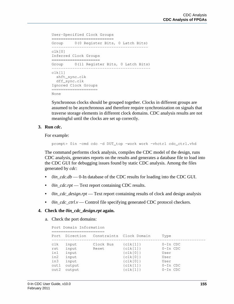
CDC AnalysisCDC Analysis of FPGAs
0-In CDC User Guide, v10.0 155February 2011
User-Specified Clock Groups===========================Group 0(0 Register Bits, 0 Latch Bits)------------------------------------------clk[0]Inferred Clock Groups=====================Group 0(11 Register Bits, 0 Latch Bits)-------------------------------------------clk[1] shft_sync.clk dff_sync.clkIgnored Clock Groups====================None
Synchronous clocks should be grouped together. Clocks in different groups areassumed to be asynchronous and therefore require synchronization on signals thattraverse storage elements in different clock domains. CDC analysis results are notmeaningful until the clocks are set up correctly.
3. Run cdc.
For example:
prompt> 0in -cmd cdc -d DUT_top -work work -vhctrl cdc_ctrl.vhd
The command performs clock analysis, compiles the CDC model of the design, runsCDC analysis, generates reports on the results and generates a database file to load intothe CDC GUI for debugging issues found by static CDC analysis. Among the filesgenerated by cdc:
• 0in_cdc.db — 0-In database of the CDC results for loading into the CDC GUI.
• 0in_cdc.rpt — Text report containing CDC results.
• 0in_cdc_design.rpt — Text report containing results of clock and design analysis
• 0in_cdc_ctrl.v — Control file specifying generated CDC protocol checkers.
4. Check the 0in_cdc_design.rpt again.
a. Check the port domains:
Port Domain Information=======================Port Direction Constraints Clock Domain Type-------------------------------------------------------------------clk input Clock Bus {clk[1]} 0-In CDCrst input Reset {clk[1]} 0-In CDCin1 input {clk[0]} Userin2 input {clk[0]} Userin3 input {clk[0]} Userout1 output {clk[1]} 0-In CDCout2 output {clk[1]} 0-In CDC

0-In CDC User Guide, v10.0156
CDC AnalysisCDC Analysis of FPGAs
February 2011
Check the inferred port domains (clock domains assigned to the ports). By default,each input port is assigned to the clock domain of its first fan-in register. Anyprimary inputs or outputs that connect to multiple clock domains or are not assignedto a clock domain are listed. Use set_cdc_port_domain directives to makeadjustments.
b. Check for black boxes.
Black Boxes:------------
cdi_master ( black_box )syncA_1 ( black_box )syncA_3 ( black_box )syncA_7 ( black_box )tctrl ( inferred )
Internal logic of the black boxes is unknown and in particular, the connectivitybetween a black box’s inputs and outputs is unknown. So, black boxes can masksome CDC problems. Check that the port domains of the user-defined black boxes(black_box in the report) are all specified.
VITAL models, FPGA library elements that are not synthesizable and design blockswith unsynthesizable constructs are inferred black boxes (inferred in the report),unless explicitly specified with set_black_box directives. Check the inferred blackboxes in 0in_cdc.rpt. If an inferred black box affects CDC results, at least oneassociated blackbox CDC scheme is reported:
Blackbox Crossing. (blackbox)-----------------------------------------------------------------tx_clk: start: tx_sig2 (/u/zin/blackbox/dut.v : 25)
<clock N/A>: end: dut.Di2 (/u/zin/dut.v: 40) (ID:blackbox_12944)
You can declare the black box as a user-defined black box (with set_black_box) andspecify the port domains for the black box’s I/O ports (with set_cdc_port_domain).The following example directives do this for an Altera dual-port RAM block:
-- 0in set_black_box altdpram-- 0in set_cdc_port_domain wren -clock inclock -module altdpram-- 0in set_cdc_port_domain data -clock inclock -module altdpram-- 0in set_cdc_port_domain wraddress -clock inclock -module altdpram-- 0in set_cdc_port_domain wraddressstall-- -clock inclock -module altdpram-- 0in set_cdc_port_domain inclocken -clock inclock -module altdpram-- 0in set_cdc_port_domain byteena -clock inclock -module altdpram-- 0in set_cdc_port_domain rden -clock outclock -module altdpram-- 0in set_cdc_port_domain rdaddress-- -clock outclock -module altdpram-- 0in set_cdc_port_domain rdaddressstall-- -clock outclock -module altdpram-- 0in set_cdc_port_domain outclocken-- -clock outclock -module altdpram-- 0in set_cdc_port_domain q -clock outclock -module altdpram-- 0in set_cdc_port_domain aclr -async -module altdpram

CDC AnalysisCDC Analysis of FPGAs
0-In CDC User Guide, v10.0 157February 2011
You might be able to obtain or write synthesizable models of various black-boxedelements. For example, using the Xilinx CoreGen tool: run Project >Project Options;select the Generation tab; and set Simulation Files: Structural. Structural models aresynthesizable. Be sure to keep the structural models and behavioral models in differentlocations to prevent overwriting previously-generated files.
Phase 4: Running GUI DebugThe 0in_cdc command runs the CDC GUI. To run 0in_cdc in GUI debug mode, specify theCDC results database as the only argument:
prompt> 0in_cdc 0in_cdc.db
At this point, debugging CDC issues with the CDC GUI is the same for FPGA-based design asit is with other designs. See “0in_cdc: GUI Debug Mode” on page 88. Also see the chapter“GUI Reference” on page 411 for details on the various GUI tools and windows. As youanalyze the CDC results, you will find RTL issues to fix, to waive and to filter out. You mightwant to add or change directives in your control file to:
• Adjust clock configurations (set_cdc_clock)
• Set clock domains of I/O ports (set_cdc_port_domain)
• Declare custom synchronizers (set_cdc_synchronizer)
• Define characteristics of certain signals in the design (set_cdc_signal)
• Reclassify the results (set_cdc_report)
•
0-In CDC User Guide, v10.0158
CDC AnalysisCDC Analysis of FPGAs
February 2011

0-In CDC User Guide, v10.0 159February 2011
Chapter 5CDC-FX Metastability Injection
Metastability injected simulation is an extension to normal RTL simulation that injects randommetastability into the circuit’s behavior. CDC-FX metastability injected simulation is similar tosimulation with assertions. But, it uses special CDC-FX checkers to inject metastability into thecircuit during simulation. These checkers also monitor the metastability logic and reportcoverage of metastability effects during simulation.

0-In CDC User Guide, v10.0160
CDC-FX Metastability InjectionSpecifying Metastability Windows
February 2011
Specifying Metastability WindowsThe metastability windows indicate the transmit/receive clock edge relations that determineswhen metastability can occur. They are specified to the ccl command using theset_cdc_fx_metastability_window global directive (see page 163). This global directivesets the metastability window for the CDC-FX clocks.
Setup and Hold Periods
Figure 5-1 shows setup and hold time periods around a register’s clock edge along with samplewaveforms for an input to the register(s). The input signal is stable if it is held at a constant 0 or1 value during the setup and hold periods. The signal is unstable if it changes during theseperiods. If the signal input to a register is unstable, then the register can become metastable.
Figure 5-1. Setup and Hold Times for a Register Input
Metastability Windows
The setup and hold times determine receive clock cycles for which a register can becomemetastable—based on the active edge of the receive clock and the value of the signal at theinput port of the register. In hardware, however, this input port switches value after the outputport driving the signal (in the transmit clock domain) switches and the new value propagates tothe input port (in the receive clock domain). This propagation delay (tprop) has the followingphysical bounds:
min tprop ≤ tprop ≤ max tprop
Accounting for propagation delay identifies a metastability window relative to each active edgeof the receive clock, as shown in Figure 5-2. A metastability window defined this way assumesthe worst case events as follows:
• CDC signal propagates as slowly as possible (max tprop) and violates the setup time(tsetup).
• CDC signal propagates as quickly as possible (min tprop) and violates the hold time(thold).
tsetup thold
rx_clk
s
s
s stable
unstable
unstable
s
stable

CDC-FX Metastability InjectionSpecifying Metastability Windows
0-In CDC User Guide, v10.0 161February 2011
Figure 5-2. Metastability Window
The start value is the number of time units before the active edge of the receive clock that themetastability window “opens.” The stop value is the number of time units after the active edgeof the receive clock that the metastability window “closes.”
Metastability Windows UsageNote the following information about metastability windows:
• Except for the default case, the metastability windows are not set automatically bysoftware. The user sets up metastability windows based on the knowledge of thehardware technology and characteristics of the design by specifying their start and stopvalues. However, the user does not need to specify setup/hold times or propagationdelay ranges.
• Each pair of transmit/receive clocks has its own metastability window (either specifiedor default). In particular, a receive clock might have multiple windows.
• If the duration of a metastability window is sufficiently large, then every active edge ofthe corresponding transmit clock falls inside the window. In this case, simulation withmetastability injectors randomly inserts metastability effects every clock cycle theregister changes value.
• A common metastability verification methodology is to start with large metastabilitywindows (for example, the default case). Then, successively narrow the windows andfocus analysis on select CDC paths. This way the user can analyze the worst casescenario (so no bugs might be missed). Then, after eliminating “false” violations, theuser can identify real problems caused by metastability intolerance.
• Metastability windows are used for metastability injected simulation. They have nocounterpart in hardware. In hardware, a changing CDC signal either does or does notresult in the receive register going metastable, and the hardware value either does ordoes not agree with the value used in plain simulation.
tsetup thold
rx_clk
metastability window
min tprop
max tprop
start stop
start = tsetup - max tprop stop = thold - min tprop

0-In CDC User Guide, v10.0162
CDC-FX Metastability InjectionSpecifying Metastability Windows
February 2011
clks_aligned[65:0]
When the assertion compiler instantiates a cdc_fx checker, it also creates clock monitor logicthat determines when the transmit clock is within the metastability window of the receive clock(for that transmit clock). Whenever this occurs, the receive register is prone to metastability ifits input value also changes in that receive clock cycle. The clks_aligned output from theclock monitor is used to pass this information to the cdc_fx checker.
The clks_aligned output is a 66-bit value that is 0 throughout “normal” cycles. When theclock monitor detects an active transmit clock edge in the corresponding metastability windowof the receive clock edge, one of the clks_aligned bits asserts a pulse that begins at thesecond active clock edge and stops at the first subsequent inactive clock edge (see Figure 5-3).
Note the following:
• clks_aligned[0] — 1 if tx_clk is before rx_clk.
• clks_aligned[1] — 1 if tx_clk is after rx_clk.
• clks_aligned[33:2] — metastability window start time.
• clks_aligned[65:34] — metastability window stop time.
Figure 5-3. clks_aligned Input to the cdc_fx Checker
metastability window
rx_clk
tx_clk
clks_aligned 0
Clocks not aligned.
metastability window
rx_clk
tx_clk
clks_aligned[0]
Clocks aligned. Transmit clock edge before (or at) receive clock edge.
metastability window
rx_clk
tx_clk
clks_aligned[1]
Clocks aligned. Receive clock edge before transmit clock edge.
CDC-FX Metastability InjectionSpecifying Metastability Windows
0-In CDC User Guide, v10.0 163February 2011
set_cdc_fx_metastability_window
The set_cdc_fx_metastability_window directive specifies a metastability window for one ormore receive register clocks. This global directive is used by the ccl command.
set_cdc_fx_metastability_window-start value -stop value [-tx_clock clock_signal] [-rx_clock clock_signal] [-percent]
Unless the directive include the -percent option, the -start and -stop values specifymetastability using directional time units as follows:
• The -start value is the number of time units before the active receive clock edge thatthe associated metastability window opens.
• The -stop value is the number of time units after the active receive clock edge that theassociated metastability window closes.
If -percent is specified, the -start and -stop values instead are percentages of the receive clockduty cycle.
If the directive specifies -tx_clock and -rx_clock, then the directive applies to cdc_fxcheckers with these clock pairs. If the directive omits -tx_clock and -rx_clock, then thedirective applies to the remaining cdc_fx checkers. It is an error to specify more than onedirective without the -tx_clock and -rx_clock arguments.
If no set_cdc_fx_metastability_window global directive is specified, then the specialdefault case described in the next section is followed. However, if at least oneset_cdc_fx_metastability_window global directive is specified, then the “default”metastability window configuration has a duration set to 0. In this case, the cdc_fx checkersnot covered by explicit set_cdc_fx_metastability_window directives never injectmetastability. Their cdc_fx checks never fire.
Note the following:
• The -tx_clock and -rx_clock arguments do not allow wildcards.
• The set_cdc_fx_metastability_window global directive does not support bussedclocks.
Special Default Case
If a set_cdc_fx_metastability_window global directive is not specified for a CDC crossing,then the (default) metastability window is set as follows (see Figure 5-4):
• The start time is 25% of the receive clock cycle before the receive clock edge.
• The stop time is 10% of the receive clock cycle after the receive clock edge.

0-In CDC User Guide, v10.0164
CDC-FX Metastability InjectionSpecifying Metastability Windows
February 2011
Figure 5-4. Metastability Window Default
For example, if rx_clk has period 100 time units, then the default metastability window is thesame as the window set by the following:
/* 0in set_cdc_fx_metastability_window-start 25 –stop 10 -tx_clock tx_clk -rx_clock rx_clk */
See also “set_cdc_fx_timescale” on page 270.
tsetup thold
rx_clk
default
start = 25% stop = 10%
windowmetastability
clock period

CDC-FX Metastability InjectionRunning CDC-FX
0-In CDC User Guide, v10.0 165February 2011
Running CDC-FXThe metastability injectors (cdc_fx checkers and metastability detection logic) are instantiatedfrom cdc_fx checker directives. The user can specify these directives manually, but CDCpaths can be numerous and this process is prone to user error. Instead, use a built-in feature ofthe cdc command to automate the process of preparing the design data for the CCL compiler.Since cdc analyzes CDC paths anyway, it can readily construct the cdc_fx checker directivesfor them. Therefore, if the user includes the -fx option to the cdc command, then it generatesa CDC-FX control file (0in_cdc_fx_sim_ctrl.v) that contains cdc_fx checker directives thatcan be used with the CCL compiler (see Figure 5-5).
Figure 5-5. CDC Data Flow for Simulation with Metastability
Figure 5-5 also shows that part of the data preparation for the CDC-FX analysis is to set up anoptional CDC-FX control file that contains the set_cdc_fx_metastability_window globaldirectives used to set the metastability windows for the cdc_fx checkers.
set_cdc_fx_checkThe set_cdc_fx_check directive turns on specified checks in corresponding cdc_fx checkerdirectives promoted by the cdc -fx command.
set_cdc_fx_check[-scheme scheme] [-tx_clock clock_signal] [-rx_clock clock_signal] [-fx][-glitch_swallowed] [-glitch_caught]
By default, the cdc_fx checker directives promoted from the cdc -fx command areconfigured as follows:
• The cdc_fx checkers on single-bit registers have no checks turned on.
• The cdc_fx checkers on multiple-bit registers have only the cdc_fx check turned on.
cdc -fx
designfiles
checkercontrol
files
ccl
simulation withmetastability
0in_cdc_fx_sim_ctrl.v
edit
CDC-FX control file(with set_cdc_fx_metastability_window directives)
CDC-FX control file(with set_cdc_fx_check directives)
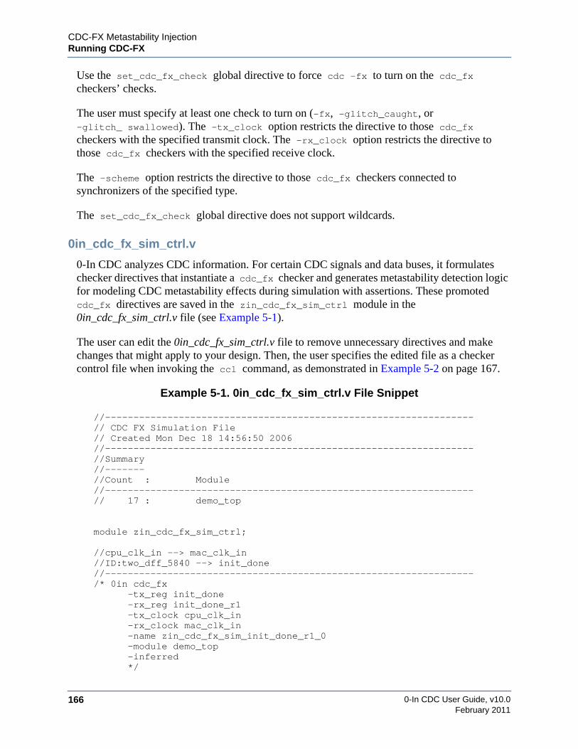
0-In CDC User Guide, v10.0166
CDC-FX Metastability InjectionRunning CDC-FX
February 2011
Use the set_cdc_fx_check global directive to force cdc -fx to turn on the cdc_fxcheckers’ checks.
The user must specify at least one check to turn on (-fx, -glitch_caught, or-glitch_ swallowed). The -tx_clock option restricts the directive to those cdc_fxcheckers with the specified transmit clock. The -rx_clock option restricts the directive tothose cdc_fx checkers with the specified receive clock.
The -scheme option restricts the directive to those cdc_fx checkers connected tosynchronizers of the specified type.
The set_cdc_fx_check global directive does not support wildcards.
0in_cdc_fx_sim_ctrl.v
0-In CDC analyzes CDC information. For certain CDC signals and data buses, it formulateschecker directives that instantiate a cdc_fx checker and generates metastability detection logicfor modeling CDC metastability effects during simulation with assertions. These promotedcdc_fx directives are saved in the zin_cdc_fx_sim_ctrl module in the0in_cdc_fx_sim_ctrl.v file (see Example 5-1).
The user can edit the 0in_cdc_fx_sim_ctrl.v file to remove unnecessary directives and makechanges that might apply to your design. Then, the user specifies the edited file as a checkercontrol file when invoking the ccl command, as demonstrated in Example 5-2 on page 167.
Example 5-1. 0in_cdc_fx_sim_ctrl.v File Snippet
//-----------------------------------------------------------------// CDC FX Simulation File// Created Mon Dec 18 14:56:50 2006//-----------------------------------------------------------------//Summary//-------//Count : Module//-----------------------------------------------------------------// 17 : demo_top
module zin_cdc_fx_sim_ctrl;
//cpu_clk_in --> mac_clk_in//ID:two_dff_5840 --> init_done//-----------------------------------------------------------------/* 0in cdc_fx
-tx_reg init_done-rx_reg init_done_r1-tx_clock cpu_clk_in-rx_clock mac_clk_in-name zin_cdc_fx_sim_init_done_r1_0-module demo_top-inferred*/

CDC-FX Metastability InjectionRunning CDC-FX
0-In CDC User Guide, v10.0 167February 2011
//cpu_clk_in --> core_clk_in//ID:no_sync_47305 --> init_done//-----------------------------------------------------------------/* 0in cdc_fx
-tx_reg init_done-rx_reg tx_state[0]-tx_clock cpu_clk_in-rx_clock core_clk_in-name zin_cdc_fx_sim_tx_state_0__1-module demo_top-inferred*/
//cpu_clk_in --> core_clk_in//ID:no_sync_2628 --> init_done//-----------------------------------------------------------------/* 0in cdc_fx
-tx_reg init_done-rx_reg tx_en-tx_clock cpu_clk_in-rx_clock core_clk_in-name zin_cdc_fx_sim_tx_en_2-module demo_top-inferred*/
. . .endmodule
Example 5-2. Editing the 0in_cdc_fx_sim_ctrl.v File
> cp 0in_cdc_fx_sim_ctrl.v cdc_fx_sim_ctrl.v> vi cdc_fx_sim_ctrl.v> 0in –cmd ccl –d design –ctrl cdc_fx_sim_ctrl.v ...
CDC-FX Checker Promotion
Table 5-1 shows the CDC schemes that promote cdc_fx checkers.
Table 5-1. CDC Schemes and cdc_fx Checker Promotion
Promote cdc_fx Checkers Do Not Promote cdc_fx Checkers
bus_dff_sync_gated_clkbus_four_latchbus_shift_regbus_two_dffbus_two_dff_phasecombo_logicdff_sync_gated_clkdmuxfanin_different_clksfour_latch
handshakemulti_bitsmulti_sync_mux_selectno_syncpulse_syncshift_regsimple_dmuxtwo_dfftwo_dff_phase
async_resetasync_reset_no_syncblackboxcustom_syncbus_custom_syncmemory_syncreconvergenceredundantsingle_source_reconvergence

0-In CDC User Guide, v10.0168
CDC-FX Metastability InjectionRunning CDC-FX
February 2011
The following situations can cause a cdc_fx checker not to be promoted, or to be promotedwith partial information:
• Individual signals from multibit registers.
• Signals from registers with different transmit clocks fan into a receive register.
• The tx_reg or the rx_reg is not a real register and custom_fx is not on. For example,it is a memory or a FIFO.
• The tx_clk or rx_clk is missing. For example, the transmit register is anasynchronous input port.
• There are latches between tx_reg and rx_reg.
• Promotions are turned off.
• Clock logic for one of the clocks has a UDP.
• RX logic uses a custom synchronizer.

CDC-FX Metastability InjectionRunning Metastability-injected Simulation
0-In CDC User Guide, v10.0 169February 2011
Running Metastability-injected SimulationMetastability-injected simulation uses the same flow as simulation with protocol checkers. The-compile_assertions option to the cdc command compiles the metastability injection logic andsets up the arguments needed to run metastability-injected simulation (Figure 5-6).
Figure 5-6. Metastability-injected Simulation
Results from metastability-injected simulation can be merged back into the CDC GUI forreview and debugging. The following procedure uses the Questa vsim simulator.
1. Set up the design library and compile the design.
For example:
prompt> vlib workprompt> vmap work workprompt> vcom dut.vhdl
2. Run CDC analysis.
Specify the -compile_assertions and the prefix showing the hierarchy path from the toplevel testbench to the DUT analyzed by cdc. Also specify -fx so cdc generates theinformation used to compile the metastability injection logic. For example:
prompt> 0in -cmd cdc -d dut -ctrl dut_ctrl.v \-compile_assertions -prefix tb.dut_inst -fx
vsim
vcom/vlog
vcom/vlog
cdc
0in_cdc
controlfiles
vcom/vlogdesign
files
GUI
debuggingenvironment
-work library-compile_assertions
-f 0in_cdc_sim.arg-f 0in_cdc_sim_vhdl.arg
testbenchfiles
0in_checksim.db
0in_cdc.db
merge

0-In CDC User Guide, v10.0170
CDC-FX Metastability InjectionRunning Metastability-injected Simulation
February 2011
3. Compile the CDC-FX metastability injection logic.
Specify the simulation arguments files generated by cdc. For example:
prompt> vlog -f 0in_cdc_sim.argprompt> vcom -f 0in_cdc_sim_vhdl.arg
4. Compile the testbench.
prompt> vlog tb.v
5. Run simulation.
Specify the PLI library path for the simulator and the vsim arguments files. For example:
prompt> vsim -c tb -pli $HOME_0IN/lib/lib0InLoadMTIPLI.so \-f 0in_cdc_sim.arg.vsim -f 0in_cdc_sim.arg.vsimrun \-do "add log -r /*; run 1000; quit -f"
6. Run the CDC GUI.
Load the 0in_cdc.db database generated by cdc and merge the 0in_checksim.db databasegenerated by vsim.
prompt> 0in_cdc 0in_cdc.db -mergedb 0in_checksim.db
Simulation ArgumentsThe user can use simulation arguments to suppress metastability injection during simulation(for individual CDC signals or all CDC signals) and to set the seed for random metastabilityinjection. The cdc_fx checkers maintain statistics, but metastability is not injected intosimulation.
+0in_suppress_fx_name+name
To suppress metastability injection during simulation for individual signals, specify them withsimulation arguments of the following form:
+0in_suppress_fx_name{+name}…
Here, name is the cdc_fx checker name. Wildcards can be used in name. For example,
+0in_suppress_fx_name+tx4_*+tx_data
+0in_disable_fx_force
To suppress metastability injection for all individual signals, specify the following argument:
+0in_disable_fx_force
Refer to “Verilog Glue Logic Option Impact” on page 171 and “VHDL Glue Logic OptionImpact” on page 173 for additional information.

CDC-FX Metastability InjectionRunning Metastability-injected Simulation
0-In CDC User Guide, v10.0 171February 2011
+0in_random_seed+n
To set the random generator seed for random metastability injection, specify the followingsimulation argument:
+0in_random_seed+n
Here, n is a positive (32-bit decimal) integer to use as the seed for the random numbergenerator. Default: 11449.
CDC-FX PLI FunctionsTestbenches can include PLI function calls that dynamically control the operation of themetastability injectors.
Note that you cannot use $0in_checker_on/$0in_checker_off or any other 0-In PLI call attime 0. In fact, it is recommended that you do not invoke any 0-In PLI call before #100 afterbeginning simulation.
$0in_always_invert_metastable_signals ();
Inverts signals when they are metastable.
Refer to “Verilog Glue Logic Option Impact” on page 171 and “VHDL Glue Logic OptionImpact” on page 173 for additional information.
$0in_never_invert_metastable_signals ();
Leaves the cdc_fx checkers active, but disables metastability injection.
Refer to “Verilog Glue Logic Option Impact” on page 171 and “VHDL Glue Logic OptionImpact” on page 173 for additional information.
$0in_randomly_invert_metastable_signals ();
Randomly injects metastability into CDC signals when they are metastable. This is the defaultbehavior.
Refer to “Verilog Glue Logic Option Impact” on page 171 and “VHDL Glue Logic OptionImpact” on page 173 for additional information.
Verilog Glue Logic Option ImpactThe differences between the following options for Verilog glue logic are described in thissection:
• ZI_NO_CDC_FORCE

0-In CDC User Guide, v10.0172
CDC-FX Metastability InjectionRunning Metastability-injected Simulation
February 2011
• +0in_disable_fx_force
• $0in_never_invert_metastable_signals
The Verilog glue logic is as follows:
initialbegin`ifdef ZI_NO_CDC_FORCE`elseif (!($test$plusargs("0in_disable_fx_force")))beginforce `int_prefix_0in.U1.U12.dout = zin_wire_sg_0; end `endifend
The options have the following impact.
ZI_NO_CDC_FORCE Option
This option can only be used during compiling the design. It permanently removes the forcestatement. For example,
% vlog +define+ZI_NO_CDC_FORCE test.v
or
% vcs +define+ZI_NO_CDC_FORCE test.v
+0in_disable_fx_force Option
This option can only be used during simulation. It disables the force statements for that specificsimulation run. For example,
% vsim tb \+0in_disable_fx_force \-f 0in_sim.arg.vsim \-pli ${HOME_0IN}/lib/lib0InLoadMTIPLI.so
or
% ./simv +0in_disable_fx_force
$0in_never_invert_metastable_signals Option
This option does not impact the force statements. It only changes the random number generatorduring simulation to always produce 0. Hence, the forced values are supposed to be identical tothe original values.
The glue logic can produce data values different from the original RTL specially for Xs. Hence,this option can result in change in simulation behavior.

CDC-FX Metastability InjectionRunning Metastability-injected Simulation
0-In CDC User Guide, v10.0 173February 2011
Sometimes a customer uses the $0in_never_invert_metastable_signals option while thechip is loading the configuration registers. During this phase, the users has external circuitry toensure that the different clocks are in sync. Next, the user enables CDC-FX by calling the$0in_randomly_invert_metastable_signals option. Also, the user has the$0in_always_invert_metastable_signals option to get better coverage if the number ofmetastable cycles is limited in the testbench.
VHDL Glue Logic Option ImpactThe differences between the following options for VHDL glue logic are described in thissection:
• ZI_NO_CDC_FORCE
• +0in_disable_fx_force
• $0in_never_invert_metastable_signals
The VHDL glue logic is as follows:
module zi_xmr_wrap;
`ifdef ZI_NO_CDC_FORCE`else
zi_cdc_fx_force_sigs_0_entity #(.prefix("/tb/U1")) i1(); `endif
endmodule
The options have the following impact.
ZI_NO_CDC_FORCE Option
Same behavior as Verilog (see “ZI_NO_CDC_FORCE Option” on page 172).
+0in_disable_fx_force Option
No impact for VHDL.
$0in_never_invert_metastable_signals Option
Same behavior as Verilog (see “$0in_never_invert_metastable_signals Option” on page 173).

0-In CDC User Guide, v10.0174
CDC-FX Metastability InjectionMetastability Injector Simulation Methodology
February 2011
Metastability Injector Simulation MethodologyMetastability injectors in simulation uncover problems that arise from CDC metastabilityeffects. These problems cannot be detected with basic simulation. Therefore, use the followingmethodology:
1. Start with a “clean” design.
o End-to-end tests run completely, without errors.
o If the design is instrumented with assertions, then plain simulation with assertionsdoes not violate any assertions.
2. Run metastability injected simulation.
3. Use the 0in_cdc database viewer to analyze the results.
o End-to-end test errors indicate receive logic is not tolerant of CDC metastabilityeffects.
o Assertion failures indicate receive logic is not tolerant of CDC metastability effects.
o The cdc_fx checker coverage shows how completely each metastability injectorcovers the range of metastability effects during simulation.
4. If needed, suppress some checkers and rerun metastability injected simulation.
5. Debug any cdc_fx checker firings. The cdc_fx checker has three transfer protocolchecks that by default are turned off.
o The cdc_fx check ensures that the data input to the receive register does notchange in a cycle for which the transmit/receive clock edges align (that is,metastability is not possible for the corresponding register). The generated cdc_fx
directives for the CDC data buses are automatically included by the tool.
o The glitch_caught check ensures that metastability injection does not catch aglitch if it is not detected by simulation.
o The glitch_swallowed check ensures that metastability injection does notswallow a glitch if it is detected by simulation.
Assertion ViolationsIf metastability injected simulation produces assertion violations (i.e., check firings), then youcan analyze them the same as you do firings from basic simulation with assertions (seeFigure 5-7 on page 175). Use the 0in_cdc viewer to examine details of the check firings and todisplay their waveforms. These violations are caused by design defects in the fan-outs of thereceiving registers that make the circuit intolerant of random delays in the transmission of theirdriving CDC signals.

CDC-FX Metastability InjectionMetastability Injector Simulation Methodology
0-In CDC User Guide, v10.0 175February 2011
Figure 5-7. CDC GUI with Merged CDC_FX Results
The cdc_fx checker entries in the viewer database provide a variety of information about themetastability injectors during simulation.
Each cdc_fx checker maintains coverage information about its performance duringsimulation. The checker entry in the simulation database (0in_checksim.db) has thisinformation.
The cdc_fx checker’s cdc_fx check fires if the active edge of the transmit clock is in themetastability window of the receive clock and the transmit data change in this window. Thesecycles are candidates for metastability injection. The Metastable Cycles evaluation statisticincrements each cycle this happens. Normally, this is not problematic. The logic in the fan-outof the receive register is expected to tolerate this situation.
Some design styles have transmitting circuitry that presumes data is stable during cycles whenboth clock edges occur in the metastability window. No metastability can occur and thereceiving logic does not need to account for CDC metastability effects. In such cases, you canuse the cdc_fx check to verify the transmit data remains stable when metastability can occur.
Notice in the Checker Report that the -rx_q field identifies the register output from theoriginal circuit that is replaced in the new circuit (remodeled with the metastability injectionlogic) with the rx_q output from the checker. When ccl compiles the design for simulation,each cdc_fx checker is connected so the output from the transmit register is routed to thecdc_fx checker and the rx_q output from the checker drives the load from the original receiveregister.
For most cycles, the transmit data is latched by the checker and passed through to the rx_qoutput when the receive clock activates. This mimics the behavior of the original circuit undernormal simulation.

0-In CDC User Guide, v10.0176
CDC-FX Metastability InjectionMetastability Injector Simulation Methodology
February 2011
But, when the checker determines it should inject metastability, randomly selected bits of therx_q output are inverted. The rx_q output reflects a corrupted value unrelated to the originaltransmission. This condition emulates data transmission metastability from crossing clockdomains. The circuit must be immune to these effects.

0-In CDC User Guide, v10.0 177February 2011
Chapter 6Command Reference
This command reference consists of five sections:
• CDC Schemes
• Control: two_dff, two_dff_phase, four_latch, pulse_sync, shift_reg,dff_sync_gated_clk, custom_sync, async_reset, async_reset_no_sync and no_sync.
• Data: bus_two_dff, bus_two_dff_phase, bus_four_latch, bus_dff_sync_gated_clk,bus_shift_reg, bus_custom_sync and multi_bits.
• Control/data: dmux, simple_dmux, multi_sync_mux_select, handshake, fifo,memory_sync and custom_sync_with_crossing.
• Potential problems: combo_logic, port_constraint_mismatch, reconvergence,single_source_reconvergence, redundant, series_redundant, fanin_different_clksand blackbox.
• Global Directives
• Clocks and domains: set_cdc_clock, and set_cdc_port_domain.
• CDC analysis: set_reset, set_cdc_preference, set_cdc_reconvergence,set_cdc_hier_preference, set_mode and set_mode_control.
• CDC schemes: set_cdc_synchronizer, set_cdc_signal and set_cdc_report,set_cdc_fifo, set_cdc_fifo_preference, set_cdc_handshake_preference,.
• Checker promotion: set_cdc_protocol.
• CDC-FX: set_cdc_fx_timescale, set_cdc_fx_metastability_window andset_cdc_fx_check.
• Netlist generation: set_black_box, set_memory, set_constant andset_constant_propagation.
• Checker generation: default_reset, use_synthesis_case_directives, exclude_checker,include_checker, disable_checker, disable_used, set_severity, set_checker_action,checker_firing_keyword and create_wire.
• Shell Commands
Utilities invoked from the system shell: vlib, vmap, vcom, vlog, verror, vdir, vdel, 0in,0in_cdc and 0in_db2ucdb.

0-In CDC User Guide, v10.0178
Command Reference
February 2011
• 0in Shell Commands
Utilities invoked from the 0in shell:cdc and cwhelp.
• Protocol/FX Checkers
CDC protocol checkers: cdc_dsel, cdc_fifo, cdc_glitch, cdc_hamming_distance_one,cdc_handshake_data, cdc_sample and cdc_sync. CDC-FX checkers: cdc_fx andcdc_custom_fx.

Command ReferenceCDC Schemes
0-In CDC User Guide, v10.0 179February 2011
CDC SchemesCDC analysis identifies logic patterns relevant to CDC verification. Groups of related patternsidentify specific classes of situations called CDC schemes. Each CDC scheme represents aspecific type of CDC synchronizer architecture or a potential CDC issue. This chapter consistsof the data sheets for the various CDC schemes (see Table 6-1). Each data sheet has thefollowing information:
• General Information — 0in_cdc message, schematic representation, description, and thefollowing information:
• Crossing Type — signal, data bus, both, or not applicable.
• Default Severity — evaluation, caution, or violation.
• Promoted Checker — CDC checker promoted to check the associated transferprotocol.
• Examples — examples of global directives that change the default behavior.
In addition, some data sheets show the following:
• Potential Problems — information about consequences you should consider.
• Notes — additional information relevant to the scheme.
Table 6-1. CDC Schemes
Type Scheme ID DescriptionDefaultSeverity
SignalSynchronizer
two_dff TWO DFFSYNCHRONIZER
Two or more in-phase flip-flops. evaluation
two_dff_phase TWO DFFSYNCHRONIZEROPPOSITEPOLARITY
Two out-of-phase flip-flops. caution
four_latch FOUR LATCHSYNCHRONIZER
Four or more cascaded latches. evaluation
pulse_sync PULSE SYNC Pulse. evaluation
shift_reg SHIFT REG Shift register. evaluation
dff_sync_gated_clk DFF GATED SYNC Two flip-flops with gated clock. caution
async_reset ASYNC RESET Asynchronous reset scheme. evaluation
async_reset_no_sync ASYNC RESET NOSYNC
Asynchronous resetscheme.with a missingsynchronizer
violation
no_sync MISSINGSYNCHRONIZER
Missing synchronizer violation orcaution
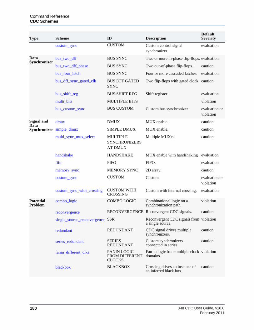
0-In CDC User Guide, v10.0180
Command ReferenceCDC Schemes
February 2011
custom_sync CUSTOM Custom control signalsynchronizer.
evaluation
DataSynchronizer
bus_two_dff BUS SYNC Two or more in-phase flip-flops. evaluation
bus_two_dff_phase BUS SYNC Two out-of-phase flip-flops. caution
bus_four_latch BUS SYNC Four or more cascaded latches. evaluation
bus_dff_sync_gated_clk BUS DFF GATEDSYNC
Two flip-flops with gated clock. caution
bus_shift_reg BUS SHIFT REG Shift register. evaluation
multi_bits MULTIPLE BITS violation
bus_custom_sync BUS CUSTOM Custom bus synchronizer evaluation orviolation
Signal andDataSynchronizer
dmux DMUX MUX enable. caution
simple_dmux SIMPLE DMUX MUX enable. caution
multi_sync_mux_select MULTIPLESYNCHRONIZERSAT DMUX
Multiple MUXes. caution
handshake HANDSHAKE MUX enable with handshaking evaluation
fifo FIFO FIFO. evaluation
memory_sync MEMORY SYNC 2D array. caution
custom_sync CUSTOM Custom. evaluation orviolation
custom_sync_with_crossing CUSTOM WITHCROSSING
Custom with internal crossing. evaluation
PotentialProblem
combo_logic COMBO LOGIC Combinational logic on asynchronization path.
violation
reconvergence RECONVERGENCE Reconvergent CDC signals. caution
single_source_reconvergence SSR Reconvergent CDC signals froma single source.
violation
redundant REDUNDANT CDC signal drives multiplesynchronizers.
caution
series_redundant SERIESREDUNDANT
Custom synchronizersconnected in series
caution
fanin_different_clks FANIN LOGICFROM DIFFERENTCLOCKS
Fan-in logic from multiple clockdomains.
violation
blackbox BLACKBOX Crossing drives an instance ofan inferred black box.
caution
Type Scheme ID DescriptionDefaultSeverity

Command Referenceasync_reset
0-In CDC User Guide, v10.0 181February 2011
async_resetASYNC RESET: Signal feeds to the asynchronous reset port of the receiving register.
Synchronization using an asynchronous reset is a standard method of synchronizing a 1-bitsignal. To detect this scheme, you must identify resets in the design (tx_rst and rx_rst) byspecifying set_reset.
Crossing Type
1-bit signal
Default Severity
evaluation
Promoted Checker
cdc_sync (if enabled, see “set_cdc_preference” on page 283).
Examples
1. Following is an example to turn severity to violation.
// 0in set_cdc_report -scheme async_reset -severity violation
2. ASYNC_RESET scheme that uses an asynchronous reset input to drive the reset pins ofthe synchronizer. Synchronizer input is tied high.
always @(posedge rx_clk,negedge tx_sig)if (!tx_sig) begins0 <= 1’b0;s1 <= 1’b0;
endelse begins0 <= 1’b1;s1 <= s0;
end
Evaluations=================================================================Asynchronous reset synchronization. (async_reset)-----------------------------------------------------------------tx_clk : start : tx_sig (async_reset1.v : 9) rx_clk : end : s0 (async_reset1.v : 10) (ID:async_reset_95442)
rx_clk
Tx Clock Domain Rx Clock Domain
tx_clk
tx_sig rx_rst
1'b1 DFF DFFrst rst
tx_rst
rx_clktx_clk
tx_sig
1'b1rst rst
s1
rx domain reset
high
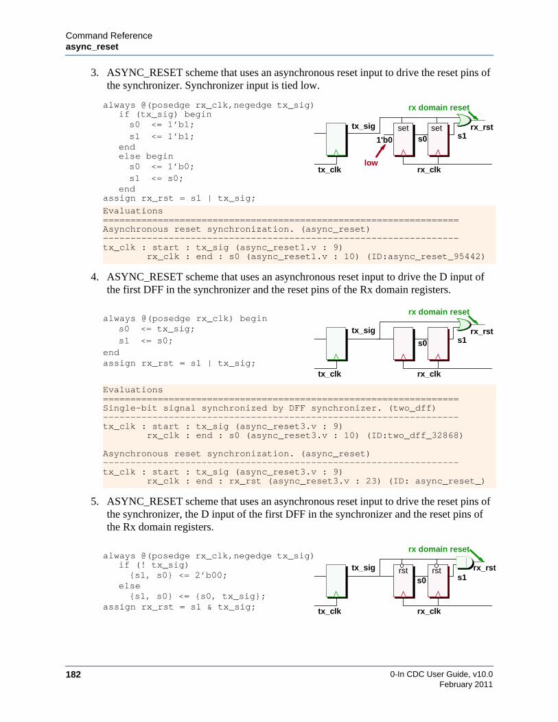
0-In CDC User Guide, v10.0182
Command Referenceasync_reset
February 2011
3. ASYNC_RESET scheme that uses an asynchronous reset input to drive the reset pins ofthe synchronizer. Synchronizer input is tied low.
4. ASYNC_RESET scheme that uses an asynchronous reset input to drive the D input ofthe first DFF in the synchronizer and the reset pins of the Rx domain registers.
5. ASYNC_RESET scheme that uses an asynchronous reset input to drive the reset pins ofthe synchronizer, the D input of the first DFF in the synchronizer and the reset pins ofthe Rx domain registers.
always @(posedge rx_clk,negedge tx_sig)if (tx_sig) begins0 <= 1’b1;s1 <= 1’b1;
endelse begins0 <= 1’b0;s1 <= s0;
endassign rx_rst = s1 | tx_sig;
Evaluations=================================================================Asynchronous reset synchronization. (async_reset)-----------------------------------------------------------------tx_clk : start : tx_sig (async_reset1.v : 9) rx_clk : end : s0 (async_reset1.v : 10) (ID:async_reset_95442)
always @(posedge rx_clk) begins0 <= tx_sig;s1 <= s0;
endassign rx_rst = s1 | tx_sig;
Evaluations=================================================================Single-bit signal synchronized by DFF synchronizer. (two_dff)-----------------------------------------------------------------tx_clk : start : tx_sig (async_reset3.v : 9) rx_clk : end : s0 (async_reset3.v : 10) (ID:two_dff_32868)
Asynchronous reset synchronization. (async_reset)-----------------------------------------------------------------tx_clk : start : tx_sig (async_reset3.v : 9) rx_clk : end : rx_rst (async_reset3.v : 23) (ID: async_reset_)
always @(posedge rx_clk,negedge tx_sig)if (! tx_sig){s1, s0} <= 2’b00;
else{s1, s0} <= {s0, tx_sig};
assign rx_rst = s1 & tx_sig;
rx_clktx_clk
tx_sig
1'b0set set
rx domain reset
s1rx_rst
s0
low
rx_clktx_clk
tx_sig
rx domain reset
s1rx_rst
s0
rx_clktx_clk
tx_sig rst rst
rx domain reset
s1rx_rst
s0
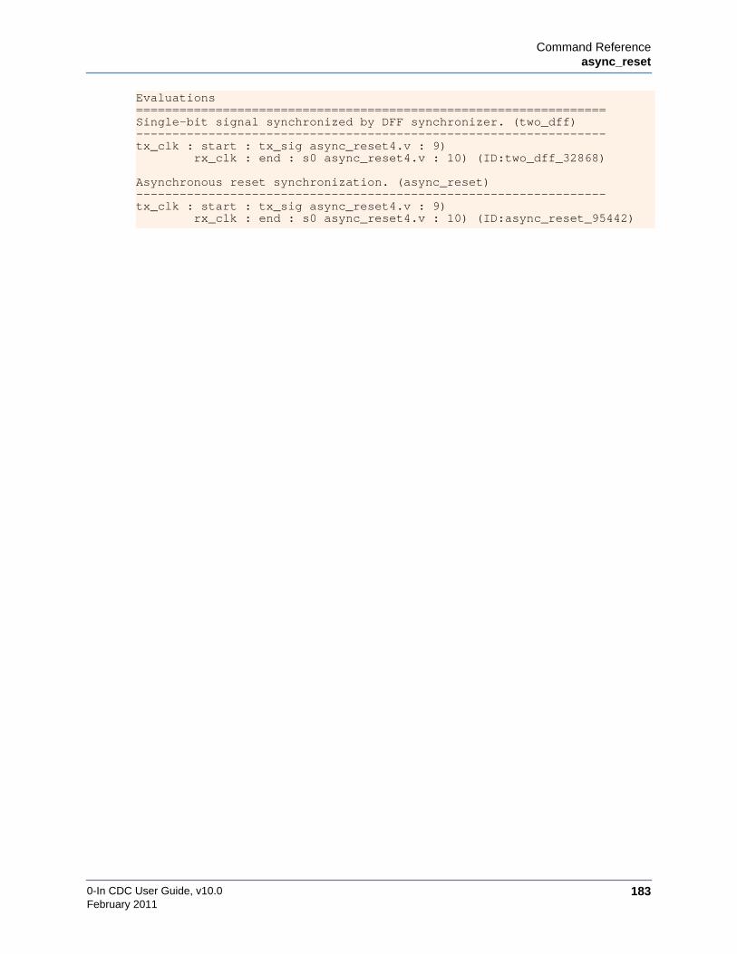
Command Referenceasync_reset
0-In CDC User Guide, v10.0 183February 2011
Evaluations=================================================================Single-bit signal synchronized by DFF synchronizer. (two_dff)-----------------------------------------------------------------tx_clk : start : tx_sig async_reset4.v : 9) rx_clk : end : s0 async_reset4.v : 10) (ID:two_dff_32868)
Asynchronous reset synchronization. (async_reset)-----------------------------------------------------------------tx_clk : start : tx_sig async_reset4.v : 9) rx_clk : end : s0 async_reset4.v : 10) (ID:async_reset_95442)

0-In CDC User Guide, v10.0184
Command Referenceasync_reset_no_sync
February 2011
async_reset_no_syncASYNC RESET NO SYNC: Signal that feeds to the asynchronous reset port of the receivingregister has no synchronizer.
Synchronization using an asynchronous reset is a standard method of synchronizing a 1-bitsignal, but the receiving register output must drive a control signal synchronizer before drivingreceive domain logic. To detect this scheme, you must identify resets in the design byspecifying set_reset.
Crossing Type
1-bit signal
Default Severity
violation
Promoted Checker
cdc_sync (if enabled, see “set_cdc_preference” on page 283).
Example
1. Following example turns reporting off:
// 0in set_cdc_report –scheme async_reset_no_sync –severity off
2. Tx signal is used as an unsynchronized reset in the Rx domain.
// Reset triggered by tx_clkalways @(posedge tx_clk)
tx_sig <= rst;
// Unsynchronized reset used in// Rx domainalways @(posedge rx_clk,negedge tx_sig)
if (!tx_sig) rx_sig <= 1’b0;else rx_sig <= din;
rx_clk
Tx Clock Domain Rx Clock Domain
tx_clk
tx_sig rx_sig
1'b1 DFFresetsynchronizer
missing
rx_clk
Tx Clock Domain Rx Clock Domain
tx_clk
tx_sig rx_reset
1'b1 DFF resetsynchronizer
incorrect
rx_clktx_clk
tx_sig rst
rx domain reset
rx_sigdin

Command Referenceasync_reset_no_sync
0-In CDC User Guide, v10.0 185February 2011
3. Tx signal is not properly synchronized as a reset in the Rx domain.
Violations=================================================================Asynchronous reset does not have proper synchronization.(async_reset_no_sync)-----------------------------------------------------------------tx_clk : start : tx_sig (test.v : 9)
rx_clk : end : rx_sig (test.v : 9) (ID:async_reset_no_sync_95911)
// Reset triggered by tx_clkalways @(posedge tx_clk)
tx_sig <= rst;
// Improperly synchronized reset used// in Rx domainalways @(posedge rx_clk,negedge tx_sig)
if (!tx_sig) rx_reset <= 1’b0;else rx_reset <= 1’b1;
Violations=================================================================Asynchronous reset does not have proper synchronization.(async_reset_no_sync)-----------------------------------------------------------------tx_clk : start : tx_sig (test2.v : 9)
rx_clk : end : rx_reset (test.v : 10) (ID:async_reset_no_sync_85287)
rx_clktx_clk
tx_sig
1'b1rst rst
improperly synchronized reset rx_reset

0-In CDC User Guide, v10.0186
Command Referenceblackbox
February 2011
blackboxBLACKBOX: Crossing drives an instance of an inferred black box.
Inferred black boxes are modules/entities containing unsupported constructs, that are notexplicitly declared as black boxes (with the set_black_box directive).
Crossing Type
control signal or data bus
Default Severity
caution
Promoted Checker
none
Examples
1. Following is an example to turn severity to violation:
// 0in set_cdc_report –scheme blackbox –severity violation
2. Following is an example of the paths for a black box crossing (from 0in_cdc.rpt):
Cautions=================================================================Blackbox Crossing. (blackbox)-----------------------------------------------------------------clk1 : start : u0.q (/u/bbox/dut.v : 41)
<clock N/A>: end : u1.b (/u/bbox/dut.v : 12) (ID:blackbox_52) via: u0.q via: u1.b
<clock N/A>: end : u1.c (/u/bbox/dut.v : 12) (ID:blackbox_53) via : u0.q via : u1.c
Following is a directive that identifies the port domains of the inferred black box:
// Blackbox ports// 0in set_cdc_port_domain b c -clock clk -module bbox_module
tx_clk
tx_siginferred
Tx Clock Domain Rx Clock Domain
black box
rx_clk

Command Referenceblackbox
0-In CDC User Guide, v10.0 187February 2011
With this directive, the port domains of the black box ports are identified in 0in_cdc.rpt:
Cautions=================================================================Blackbox Crossing. (blackbox)-----------------------------------------------------------------clk1 : start : u0.q (/u/bbox/dut.v : 41)
clk3: end : u1.b (/u/bbox/dut.v : 12) (ID:blackbox_52) via: u0.q
clk3: end : u1.c (/u/bbox/dut.v : 12) (ID:blackbox_53) via: u0.q
In this case, the port domain of the driver (u1.q) was set by a set_cdc_port_domaindirective:
// 0in set_cdc_port_domain q -clock clk3
3. Following example shows an instance (BB) of a module (black_box) that cdc hasinferred to be a black box.
By default, the datain inputs are assumed to be in different clock domains. Similarly,dout and stout are assumed to be in different clock domains. To make static CDCanalysis more accurate and to reduce the clock domain complexity, identify the portdomains of the black box data ports. For example:
// Input port domains// 0in set_cdc_port_domain datain0 -async -module black_box// 0in set_cdc_port_domain datain1 -async -module black_box// 0in set_cdc_port_domain datain2 -clock clock -module black_box// 0in set_cdc_port_domain datain3 -clock clock -module black_box
// Outrput port domains// 0in set_cdc_port_domain dataout -clock clock -module black_box// 0in set_cdc_port_domain status -clock clock -module black_box
Note that these are the port domains (not clock domains) for the data ports. Domains areidentified according to the black box’s clock pins (not external clock signals).
rx_clk
tx_clkdout
instance of an
datain1
datain2
datain3clock
reset
dataout
status
datain0
BBstatout
inferred black box
rst
din0
din1
din2din3

0-In CDC User Guide, v10.0188
Command Referenceblackbox
February 2011
Cautions=================================================================Multiple-bit signal across clock domain boundary. (multi_bits)-----------------------------------------------------------------rx_clk : start : BB.dataout (blackbox.v : 40)
tx_clk : end : dout (blackbox.v : 21) (ID:multi_bits_47389)
Blackbox Crossing. (blackbox)-----------------------------------------------------------------tx_clk : start : din1 (blackbox.v : 25)
<clock N/A> : end : BB.datain1 (blackbox.v : 40)(ID:blackbox_12944)
Evaluations=================================================================Blackbox Crossing. (blackbox)-----------------------------------------------------------------tx_clk : start : din0 (blackbox.v : 24)
<clock N/A> : end : BB.datain0 (blackbox.v : 40)(ID:blackbox_48560)
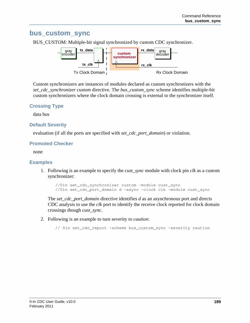
Command Referencebus_custom_sync
0-In CDC User Guide, v10.0 189February 2011
bus_custom_syncBUS_CUSTOM: Multiple-bit signal synchronized by custom CDC synchronizer.
Custom synchronizers are instances of modules declared as custom synchronizers with theset_cdc_synchronizer custom directive. The bus_custom_sync scheme identifies multiple-bitcustom synchronizers where the clock domain crossing is external to the synchronizer itself.
Crossing Type
data bus
Default Severity
evaluation (if all the ports are specified with set_cdc_port_domain) or violation.
Promoted Checker
none
Examples
1. Following is an example to specify the cust_sync module with clock pin clk as a customsynchronizer:
//0in set_cdc_synchronizer custom -module cust_sync//0in set_cdc_port_domain d -async -clock clk -module cust_sync
The set_cdc_port_domain directive identifies d as an asynchronous port and directsCDC analysis to use the clk port to identify the receive clock reported for clock domaincrossings though cust_sync.
2. Following is an example to turn severity to caution:
// 0in set_cdc_report -scheme bus_custom_sync -severity caution
rx_clk
Tx Clock Domain Rx Clock Domain
tx_clk
tx_data rx_datagrayencoder
graydecodercustom
synchronizer

0-In CDC User Guide, v10.0190
Command Referencebus_custom_sync
February 2011
3. Custom synchronizer for the Tx signal:
Use the set_cdc_synchronizer custom directive to identify custom synchronizermodules/entities:
// 0in set_cdc_synchonizer custom syncA
Custom synchronizers are considered inferred black boxes for CDC analysis, so youmust specify their port information:
/* 0in set_cdc_port_domain -input din -async -clock rx_clk-module syncA */
/* 0in set_cdc_port_domain -output dout -clock rx_clock-module syncA */
Potential Problem
CDC analysis does not promote a checker for this scheme. You should implement a transferprotocol checking scheme using one or more checkers.
// Custom sync instancesyncA S (rx_clk, tx_sig, rx_sig);
always @(posedge tx_clk)tx_sig <= data;
Evaluations=================================================================Custom CDC Scheme: syncA (custom_sync)-----------------------------------------------------------------tx_clk : start : tx_sig (custom_sync.v : 21)
rx_clk : end : S.din (custom_sync.v : 29) (ID:custom_sync_5359)
rx_clktx_clk
tx_sig syncA rx_sigdin dout
clk
data

Command Referencebus_dff_sync_gated_clk
0-In CDC User Guide, v10.0 191February 2011
bus_dff_sync_gated_clkBUS DFF GATED SYNC: Multiple-bit signals synchronized with DFF synchronizer withgated clock.
Synchronization using two flip-flops is a standard method of synchronizing a 1-bit signal, butone of the flip-flops is clocked by a gated version of the receive clock.
Crossing Type
multiple-bit data bus
Default Severity
caution
Promoted Checker
cdc_hamming_distance_one (cdc_hamming1)
Examples
1. Following is an example to turn severity to caution:
/* 0in set_cdc_report -scheme bus_dff_sync_gated_clk-severity caution */
2. Following is an example to turn off reporting for a particular CDC signal:
/* 0in set_cdc_report -scheme bus_dff_sync_gated_clk-severity off -from in1 -to r1 */
3. Bus 2 DFF synchronizer has one FF clocked by a gated version of the Rx clock.:
//gated Rx clockassign gclk = rx_clk & en;
// 1st flip-flop triggered by// the gated clockalways @(posedge gclk)
sync1 <= tx_reg;
// 2nd flip-flop triggered by// the Rx clockalways @(posedge rx_clk)
sync2 <= sync1;
tx_clk
tx_data rx_data
rx_clk
Tx Clock Domain Rx Clock Domain
DFFDFF
en_rx_clk
tx_clk
tx_reg
rx_clken
sync1 sync2
gclk
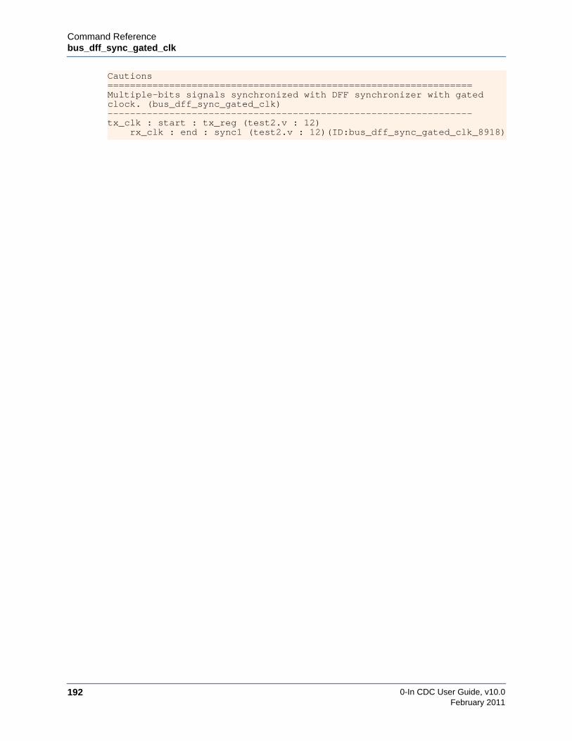
0-In CDC User Guide, v10.0192
Command Referencebus_dff_sync_gated_clk
February 2011
Cautions=================================================================Multiple-bits signals synchronized with DFF synchronizer with gatedclock. (bus_dff_sync_gated_clk)-----------------------------------------------------------------tx_clk : start : tx_reg (test2.v : 12)
rx_clk : end : sync1 (test2.v : 12)(ID:bus_dff_sync_gated_clk_8918)

Command Referencebus_four_latch
0-In CDC User Guide, v10.0 193February 2011
bus_four_latchBUS SYNC: Multiple-bit signal synchronized by latch synchronizer.
Synchronization using four latches is a standard method of synchronizing a gray-coded databus. Gray coding (i.e., hamming distance 1) assures that only one bit of data changes in anycycle, so a four-latch synchronizer (typically used for 1-bit signal crossings) is appropriate if thedata changes only at the frequency of the receiving domain.
Crossing Type
multiple-bit data bus
Default Severity
evaluation
Promoted Checker
cdc_hamming_distance_one (cdc_hammimg1)
Examples
1. Following is an example to turn severity to violation:
// 0in set_cdc_report –scheme bus_four_latch –severity violation
2. Following is an example to turn off promotion:
/* 0in set_cdc_report –scheme bus_four_latch-severity caution –promotion off */
3. Example promoted transfer protocol checker for four_latch synchronization scheme:
// Synchronized multibit variable q/* 0in cdc_hamming1 -tx_clock clk3 -tx_var r1
-name cdc_data_0 -module test -inferred */
rx_clk
Tx Clock Domain Rx Clock Domain
tx_clk
tx_data rx_datalatch latch latch latch latch
grayencoder
graydecoder

0-In CDC User Guide, v10.0194
Command Referencebus_four_latch
February 2011
4. Bus four-latch synchronizer:
Potential Problem
Four-latch synchronization of a data bus assumes the bus is gray-coded. Any data buses thatcross clock domains that are not gray-coded should be identified as requiring complete datasynchronization. Any of these crossings synchronized by four-latch synchronizers should beflagged as violations. To set these schemes to violations, use the set_cdc_report directive.
/* 0in set_cdc_report -scheme bus_four_latch-tx_clock clk_a -severity violation */
always @ (*)if (rx_clk) beginsync1 <= tx_sig;// 1st latchsync3 <= sync2; // 3rd latch
endelse beginsync2 <= sync1; // 2nd latchrx_sig <= sync3;// 4th latch
end
Evaluations=================================================================Multiple-bit signal synchronized by latch synchronizer (bus_four_latch)-----------------------------------------------------------------tx_clk : start: tx_sig (bus_four_latch.v : 8)
rx_clk: end : sync1 (bus_four_latch.v : 8) (ID:bus_four_latch_51294) via : sync1
rx_clktx_clk
tx_sig rx_sig

Command Referencebus_shift_reg
0-In CDC User Guide, v10.0 195February 2011
bus_shift_regSHIFT REG: Multiple-bit signal synchronized by shift-register synchronization.
Synchronization using a shift register is a standard method of synchronizing a gray-coded databus. Gray coding (i.e., hamming distance 1) assures that only one bit of data changes in anycycle, so a shift register (typically used for 1-bit signal crossings) is appropriate if the datachanges only at the frequency of the receiving domain. This CDC scheme is equivalent tosynchronization with two or more in-phase flip-flops.
Crossing Type
multiple-bit data bus
Default Severity
evaluation
Promoted Checker
cdc_hamming_distance_one (cdc_hamming1)
Examples
1. Following is an example to turn severity to violation:
// 0in set_cdc_report –scheme bus_shift_reg –severity violation
2. Following is an example to turn off promotion:
// 0in set_cdc_report –severity evaluation –promotion off
3. Example promoted transfer protocol checker for “bus_shift_reg” synchronizationscheme:
/* 0in cdc_hamming_distance_one-tx_var u0.q -tx_clock clk1-name cdc_hamming1_0 -module dut -inferred */
rx_clktx_clk
tx_data rx_data
Tx Clock Domain Rx Clock Domain
shift register

0-In CDC User Guide, v10.0196
Command Referencebus_shift_reg
February 2011
4. Bus shift register synchronizer:
// 2-level shift registeralways @ (posedge rx_clk)
{sync[1], sync[0]} <= {sync[0], tx_data};
Evaluations=================================================================Multiple-bit signal synchronized by shift-register synchronizer(bus_shift_reg)-----------------------------------------------------------------tx_clk : start : tx_data (bus_shift_reg.v : 10)
rx_clk : end : sync[0] (bus_shift_reg.v : 19 (ID:bus_shift_reg_99229)
tx_clk
sync[1]shift registertx_data
sync[0]
[0]
[1]synchronized data
rx_clk

Command Referencebus_two_dff
0-In CDC User Guide, v10.0 197February 2011
bus_two_dffBUS SYNC: Multiple-bit signal synchronized by DFF synchronizer.
Synchronization using two flip-flops is a standard method of synchronizing a gray-coded databus. Gray coding (i.e., hamming distance 1) assures that only one bit of data changes in anycycle, so a 2DFF synchronizer (typically used for 1-bit signal crossings) is appropriate if thedata changes only at the frequency of the receiving domain.
Crossing Type
multiple-bit data bus
Default Severity
evaluation
Promoted Checker
cdc_hamming_distance_one (cdc_hammimg1)
Examples
1. Following is an example to turn severity to violation:
// 0in set_cdc_report –scheme bus_two_dff –severity violation
2. Following is an example to turn off promotion:
// 0in set_cdc_report –scheme bus_two_dff-severity caution –promotion off */
3. Example promoted transfer protocol checker for bus_two_dff synchronization scheme:
// Synchronized multibit variable U1.U1.dsyncr/* 0in cdc_hamming1
-tx_clock clk1 -tx_var U1.U1.dinr-name cdc_data_1 -module dut –inferred */
4. Bus 2 DFF synchronizer:
reg [width-1:0] tx_reg, rx_reg;reg [width-1:0] sync1, sync2;
always @(posedge rx_clk) beginsync1 <= tx_reg; // 1st FFsync2 <= sync1; // 2nd FF
end
rx_clk
Tx Clock Domain Rx Clock Domaintx_clk
tx_data rx_dataDFF DFF
grayencoder
graydecoder
tx_clk
tx_reg
rx_clk
sync1 sync2

0-In CDC User Guide, v10.0198
Command Referencebus_two_dff
February 2011
5. Bus 2 DFF synchronizer with enable. CDC analysis only recognizes this instance as abus_two_dff scheme if set_cdc_preference -allow_enable_in_sync is specified.
Potential Problem
The 2DFF synchronization of a data bus assumes the bus is gray-coded. Any data buses thatcross clock domains that are not gray-coded should be identified as requiring complete datasynchronization. Any of these crossings synchronized by 2DFF synchronizers should beflagged as violations. To set these schemes to violations, use the set_cdc_report directive.
/* 0in set_cdc_report -scheme bus_two_dff-tx_clock clk_a -severity violation */
Notes
If you use a DFF synchronization scheme that has more than two flip-flops, then you can getCDC analysis to recognize the scheme by specifying a set_cdc_synchronizer global directive.
For example, the following global CDC directive identifies 4 DFF synchronizers as valid“two_dff” schemes for CDC paths from the tx_clk domain to the rx_clk domain:
/* 0in set_cdc_synchronizer dff -level 4-tx_clock tx_clk -rx_clock rx_clk */
Evaluations=================================================================Multiple-bit signal synchronized by DFF synchronizer. (bus_two_dff)-----------------------------------------------------------------tx_clk : start : tx_reg (bus_two_dff.v : 11) rx_clk : end : sync1 (bus_two_dff.v : 11) (ID:bus_two_dff_8942)
reg [width-1:0] tx_reg, rx_reg;reg [width-1:0] sync1, sync2;
always @(posedge rx_clk)if (enable)beginsync1 <= tx_reg; // 1st FFsync2 <= sync1; // 2nd FF
end
Evaluations=================================================================Multiple-bit signal synchronized by DFF synchronizer. (bus_two_dff)-----------------------------------------------------------------tx_clk : start : tx_reg (bus_two_dff_en.v : 11)
rx_clk : end : sync1 (bus_two_dff_en.v : 11) (ID:bus_two_dff_8942)
tx_clk
tx_reg
rx_clk
sync1 sync2EN EN
enable
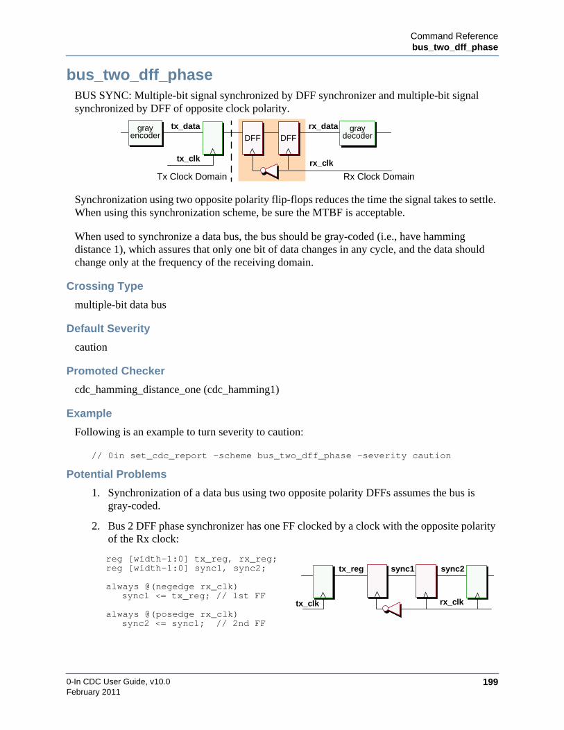
Command Referencebus_two_dff_phase
0-In CDC User Guide, v10.0 199February 2011
bus_two_dff_phaseBUS SYNC: Multiple-bit signal synchronized by DFF synchronizer and multiple-bit signalsynchronized by DFF of opposite clock polarity.
Synchronization using two opposite polarity flip-flops reduces the time the signal takes to settle.When using this synchronization scheme, be sure the MTBF is acceptable.
When used to synchronize a data bus, the bus should be gray-coded (i.e., have hammingdistance 1), which assures that only one bit of data changes in any cycle, and the data shouldchange only at the frequency of the receiving domain.
Crossing Type
multiple-bit data bus
Default Severity
caution
Promoted Checker
cdc_hamming_distance_one (cdc_hamming1)
Example
Following is an example to turn severity to caution:
// 0in set_cdc_report –scheme bus_two_dff_phase –severity caution
Potential Problems
1. Synchronization of a data bus using two opposite polarity DFFs assumes the bus isgray-coded.
2. Bus 2 DFF phase synchronizer has one FF clocked by a clock with the opposite polarityof the Rx clock:
reg [width-1:0] tx_reg, rx_reg;reg [width-1:0] sync1, sync2;
always @(negedge rx_clk)sync1 <= tx_reg; // 1st FF
always @(posedge rx_clk)sync2 <= sync1; // 2nd FF
rx_clk
Tx Clock Domain Rx Clock Domain
tx_clk
tx_data rx_dataDFF DFF
grayencoder
graydecoder
tx_clk
tx_reg
rx_clk
sync1 sync2
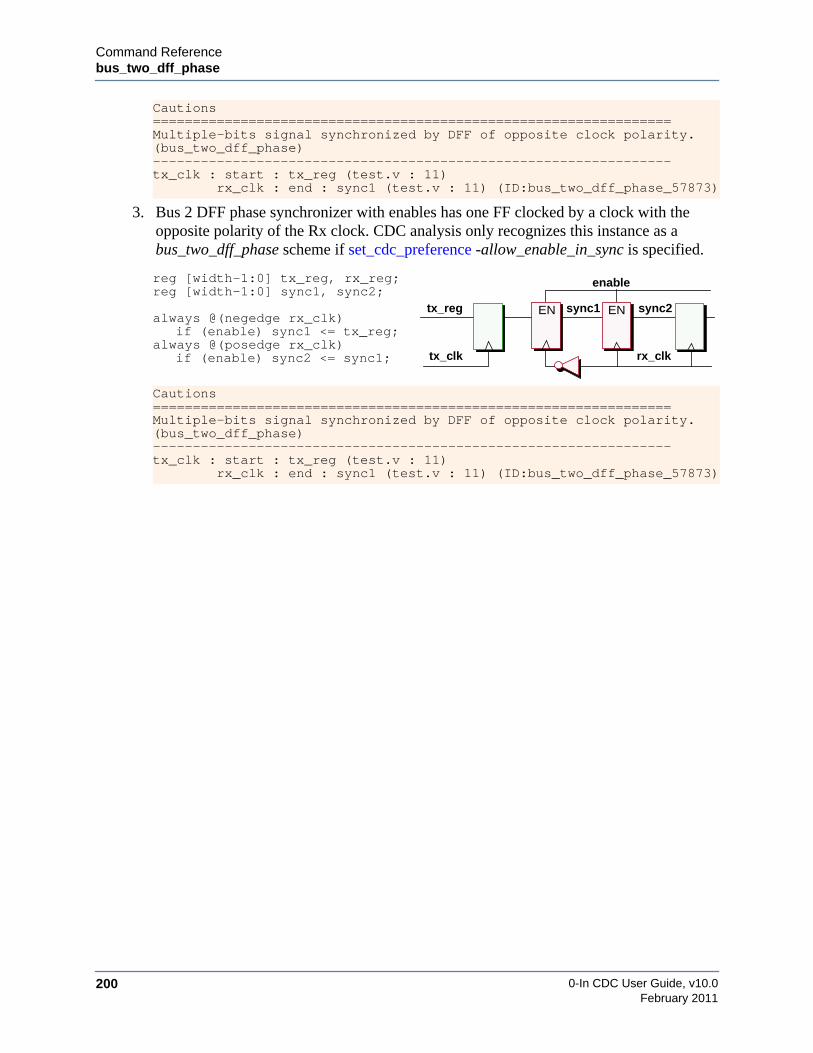
0-In CDC User Guide, v10.0200
Command Referencebus_two_dff_phase
February 2011
3. Bus 2 DFF phase synchronizer with enables has one FF clocked by a clock with theopposite polarity of the Rx clock. CDC analysis only recognizes this instance as abus_two_dff_phase scheme if set_cdc_preference -allow_enable_in_sync is specified.
Cautions=================================================================Multiple-bits signal synchronized by DFF of opposite clock polarity.(bus_two_dff_phase)-----------------------------------------------------------------tx_clk : start : tx_reg (test.v : 11) rx_clk : end : sync1 (test.v : 11) (ID:bus_two_dff_phase_57873)
reg [width-1:0] tx_reg, rx_reg;reg [width-1:0] sync1, sync2;
always @(negedge rx_clk)if (enable) sync1 <= tx_reg;
always @(posedge rx_clk)if (enable) sync2 <= sync1;
Cautions=================================================================Multiple-bits signal synchronized by DFF of opposite clock polarity.(bus_two_dff_phase)-----------------------------------------------------------------tx_clk : start : tx_reg (test.v : 11) rx_clk : end : sync1 (test.v : 11) (ID:bus_two_dff_phase_57873)
tx_clk
tx_reg
rx_clk
sync1 sync2EN EN
enable

Command Referencecombo_logic
0-In CDC User Guide, v10.0 201February 2011
combo_logicCOMBO LOGIC: Combinational logic before synchronizer.
Combinational logic in a synchronization path is a significant problem for synchronized signals,because the data used to determine an acceptable failure rate on synchronization paths assumesa single transition on a CDC signal during each clock period. But if combinational logic isplaced on the path, then this assumption is false because of glitch propagation. As a result, theerror rate rises significantly. To address this problem, you should remove all combinationallogic from the logic path.
Static CDC analysis checks for combo logic in every CDC path that has a detectedsynchronizer. For some cases, this combinational logic will be constant during normaloperation, so glitches cannot be generated. For example, the combinational logic might consistof test MUXes or configuration logic. To remove the violation, identify the signal feeding thatlogic as a constant value using set_constant.
Crossing Type
control signal or data bus
Default Severity
violation
Promoted Checker
cdc_glitch
Examples
1. Following is an example to specify that the MUX select in the combinational logicfeeding a CDC signal is constant 1'b0 (so the crossing can be checked for propersynchronization):
// 0in set_constant test_sel 1'b0
2. Following is an example to turn severity for the CDC signal en to caution:
/* 0in set_cdc_report -scheme combo_logic-severity caution -from dut.U0.en
rx_clk
Tx Clock Domain Rx Clock Domain
tx_clk
tx_data rx_datasynchronizer
combinational logic

0-In CDC User Guide, v10.0202
Command Referencecombo_logic
February 2011
3. Combinational logic between the Tx signal and a 2DFF synchronizer:
The report for this violation shows the base type CDC scheme identified by CDCanalysis (TWO DFF SYNCHRONIZER). To remove this violation—and instead reportthe crossing as a 2DFF scheme—you can specify that din is stable. That is, it is properlysynchronized in the Rx domain:
// 0in set_cdc_signal din -stable
always @ (posedge rx_clk) begins1 <= tx_sig & din;s2 <= s1;
end
Violations=================================================================Combinational logic before synchronizer. (combo_logic)-----------------------------------------------------------------tx_clk : start : tx_reg (combo_logic.v : 8)
rx_clk : end : sync1 (combo_logic.v : 8) (ID:combo_logic_57762)Base Type : TWO DFF SYNCHRONIZER
rx_clktx_clk
tx_sig DFF DFF
s2s1din
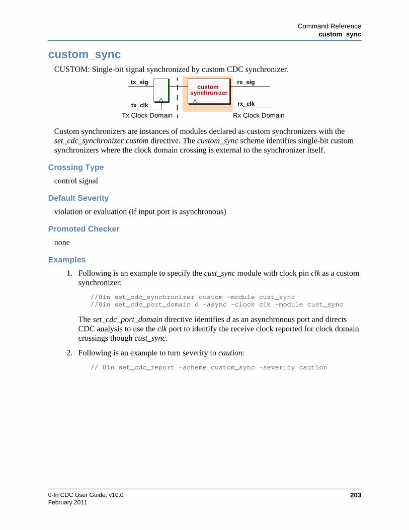
Command Referencecustom_sync
0-In CDC User Guide, v10.0 203February 2011
custom_syncCUSTOM: Single-bit signal synchronized by custom CDC synchronizer.
Custom synchronizers are instances of modules declared as custom synchronizers with theset_cdc_synchronizer custom directive. The custom_sync scheme identifies single-bit customsynchronizers where the clock domain crossing is external to the synchronizer itself.
Crossing Type
control signal
Default Severity
violation or evaluation (if input port is asynchronous)
Promoted Checker
none
Examples
1. Following is an example to specify the cust_sync module with clock pin clk as a customsynchronizer:
//0in set_cdc_synchronizer custom -module cust_sync//0in set_cdc_port_domain d -async -clock clk -module cust_sync
The set_cdc_port_domain directive identifies d as an asynchronous port and directsCDC analysis to use the clk port to identify the receive clock reported for clock domaincrossings though cust_sync.
2. Following is an example to turn severity to caution:
// 0in set_cdc_report -scheme custom_sync -severity caution
rx_clk
Tx Clock Domain Rx Clock Domain
tx_clk
tx_sig rx_sigcustom
synchronizer

0-In CDC User Guide, v10.0204
Command Referencecustom_sync
February 2011
3. Custom synchronizer for the Tx signal:
Use the set_cdc_synchronizer custom directive to identify custom synchronizermodules/entities:
// 0in set_cdc_synchonizer custom syncA
Custom synchronizers are considered inferred black boxes for CDC analysis, so youmust specify their port information:
/* 0in set_cdc_port_domain -input din -async -clock rx_clk-module syncA */
/* 0in set_cdc_port_domain -output dout -clock rx_clock-module syncA */
Potential Problem
CDC analysis does not promote a checker for this scheme. You should implement a transferprotocol checking scheme using one or more checkers.
// Custom sync instancesyncA S (rx_clk, tx_sig, rx_sig);
always @(posedge tx_clk)tx_sig <= data;
Violations=================================================================Custom CDC Scheme: syncA (custom_sync)-----------------------------------------------------------------tx_clk : start : tx_sig (custom_sync.v : 21)
rx_clk : end : S.din (custom_sync.v : 29) (ID:custom_sync_5359)
rx_clktx_clk
tx_sig syncA rx_sigdin dout
clk
data

Command Referencecustom_sync_with_crossing
0-In CDC User Guide, v10.0 205February 2011
custom_sync_with_crossingCUSTOM WITH CROSSING: Custom CDC synchronizer with an internal clock domaincrossing.
Custom synchronizers are instances of modules declared as custom synchronizers with theset_cdc_synchronizer custom directive. The custom_sync_with_crossing scheme identifiescustom synchronizers where the clock domain crossing is internal to the synchronizer itself. Toidentify this type of custom synchronizer, you must identify a transmit clock port and a receiveclock port using the set_cdc_port_domain directive for the custom synchronizer module. Everyother signal/data port must be identified with either a transmit clock or a receive clock. If a portis identified as an -async port, the synchronizer is reported as a simple custom_sync scheme.
Crossing Type
control signal or data bus
Default Severity
evaluation
Promoted Checker
none
Examples
1. Custom synchronizer module with crossing:
// 0in set_cdc_synchronizer custom -module SYNC_VX// 0in set_cdc_port_domain IN -tx_clock CLKA -module SYNC_VX// 0in set_cdc_port_domain RST_A -clock CLKA -module SYNC_VX// 0in set_cdc_port_domain OUT -rx_clock CLKB -module SYNC_VX// 0in set_cdc_port_domain RST_B -clock CLKB -module SYNC_VX
rx_clk
Tx Clock Domain Rx Clock Domaintx_clk
tx_data rx_data
custom synchronizer
internal crossing
CLKBCLKA
IN OUT
SYNC_VXRST_A RST_B
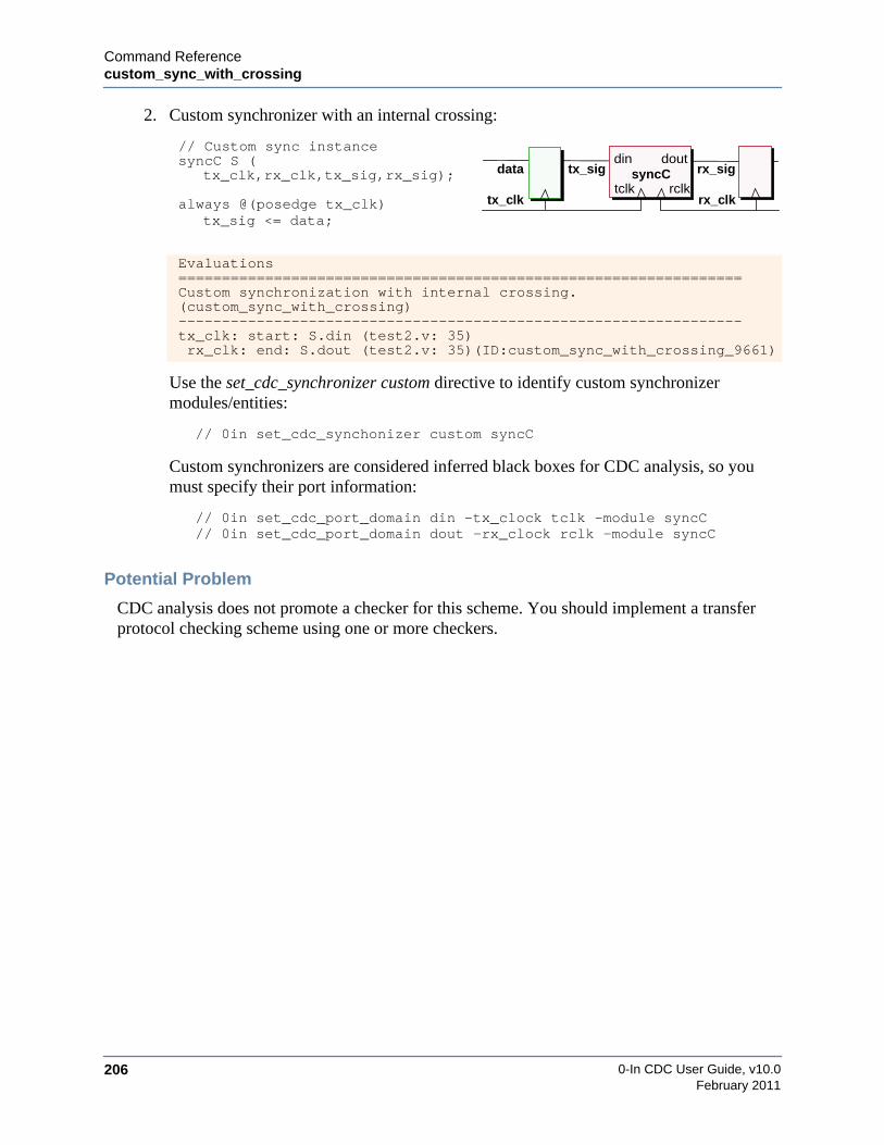
0-In CDC User Guide, v10.0206
Command Referencecustom_sync_with_crossing
February 2011
2. Custom synchronizer with an internal crossing:
Use the set_cdc_synchronizer custom directive to identify custom synchronizermodules/entities:
// 0in set_cdc_synchonizer custom syncC
Custom synchronizers are considered inferred black boxes for CDC analysis, so youmust specify their port information:
// 0in set_cdc_port_domain din -tx_clock tclk -module syncC// 0in set_cdc_port_domain dout -rx_clock rclk -module syncC
Potential Problem
CDC analysis does not promote a checker for this scheme. You should implement a transferprotocol checking scheme using one or more checkers.
// Custom sync instancesyncC S (
tx_clk,rx_clk,tx_sig,rx_sig);
always @(posedge tx_clk)tx_sig <= data;
Evaluations=================================================================Custom synchronization with internal crossing.(custom_sync_with_crossing)-----------------------------------------------------------------tx_clk: start: S.din (test2.v: 35)rx_clk: end: S.dout (test2.v: 35)(ID:custom_sync_with_crossing_9661)
rx_clktx_clk
tx_sig syncC rx_sigdin dout
tclk
data
rclk

Command Referencedff_sync_gated_clk
0-In CDC User Guide, v10.0 207February 2011
dff_sync_gated_clkDFF GATED SYNC: DFF synchronizer with gated clock.
Synchronization using two flip-flops is a standard method of synchronizing a 1-bit signal.
Crossing Type
1-bit signal
Default Severity
caution
Promoted Checker
cdc_sync
Examples
1. Following is an example to turn severity to caution:
// 0in set_cdc_report –scheme dff_sync_gated_clk –severity caution
2. Following is an example to turn off reporting for a particular CDC signal:
/* 0in set_cdc_report -scheme dff_sync_gated_clk -severity off-from in1 -to r1 */
3. Single-bit signal synchronized by 2DFF synchronizer with a gated clock:
// gated clock expressionassign gclk = rx_clk & clk_en;always @(posedge gclk)
sync1 <= tx_sig; // 1st DFFalways @(posedge rx_clk)
sync2 <= sync1; // 2nd DFF
Cautions=================================================================DFF synchronizer with gated clock. (dff_sync_gated_clk)-----------------------------------------------------------------tx_clk: start: tx_reg (test4.v : 9)
rx_clk: end: sync1 (test4.v: 9)(ID:dff_sync_gated_clk_11747)
tx_clk
tx_sig rx_sig
rx_clk
Tx Clock Domain Rx Clock Domain
DFFDFF
en_rx_clk
rx_clktx_clk
tx_sig sync2DFF DFF
sync1
clk_en

0-In CDC User Guide, v10.0208
Command Referencedmux
February 2011
dmuxDMUX: DMUX synchronization.
Synchronization using a DMUX scheme is a standard method of synchronizing a data bus (or acontrol signal). The control signal can be synchronized by any of the following signalsynchronizers: bus_dff_sync_gated_clk, bus_four_latch, bus_shift_reg, bus_two_dff,bus_two_dff_phase or two_dff_phase, dff_sync_gated_clk, four_latch. shift_reg, two_dff,pulse_sync and custom.
NoteThe physical design of the MUX logic (that controls the path from the Tx register to theRx registers) must not allow glitches at the input to an Rx register when the Tx registerchanges value.
The DMUX scheme is similar to the SIMPLE_DMUX scheme. A SIMPLE_DMUX scheme isa strict version of MUX synchronization logic that requires a receive register, a MUX andfeedback from the receiver to the MUX. A DMUX scheme is a generalized version of a MUXsynchronization circuit. The MUXing logic can be any combinational logic and a feedback pathfrom the Rx domain is not needed.
Crossing Type
synchronized control signal
Default Severity
caution
Promoted Checker
cdc_dsel
Promoted CDC-FX Checker
cdc_fx check is on by default.
tx_clk
tx_data rx_data
rx_clk
Tx Clock Domain Rx Clock Domain
tx_clk
tx_selrx_selDFFDFF
MUX

Command Referencedmux
0-In CDC User Guide, v10.0 209February 2011
Examples
1. Following is an example to turn severity to evaluation:
// 0in set_cdc_report -scheme dmux -severity evaluation
2. Following is an example to turn off promotion:
/* 0in set_cdc_report -scheme dmux-severity evaluation -promotion off */
3. Example promoted transfer protocol checker for DMUX synchronization scheme:
/* 0in cdc_dsel-tx_data isyncdbus.data_reg -tx_clock clk1-rx_clock clk2 -tx_data_select 1'b0-rx_data_select (isyncdbus.stage3_q ^ isyncdbus.isync.out)-tx_min `P_clk1_clk2_tx_min-name cdc_dsel_1 -module test -inferred */
4. 4-bit bus synchronized by a DMUX synchronizer:
always @(posedge rx_clk)begin: DMUX
reg s1, rx_sel;s1 <= tx_sel; // 1st DFFrx_sel <= s1; // 2nd DFFif (rx_sel)rx_data <= tx_data;
elserx_data <= rx_data ^ 4’b1111;
end
Cautions=================================================================DMUX synchronization. (dmux)-----------------------------------------------------------------tx_clk : start : tx_data (dmux.v : 9) rx_clk : end : rx_data (dmux.v : 6) (ID:dmux_39152)
Synchronizer ID : two_dff_44468
Evaluations=================================================================Single-bit signal synchronized by DFF synchronizer. (two_dff)-----------------------------------------------------------------tx_clk : start : tx_sel (dmux.v : 10) rx_clk : end : DMUX.s1 (dmux.v : 22) (ID:two_dff_44468)
tx_clk
tx_datarx_data
rx_clk
tx_selrx_selDFFDFF
MUX
s1
4’b1111

0-In CDC User Guide, v10.0210
Command Referencefanin_different_clks
February 2011
fanin_different_clksFANIN LOGIC FROM DIFFERENT CLOCKS: Fan-in logic from multiple clock domains.
Fan-in logic for the input to a synchronizer must be synchronized to a single transmit clockdomain for CDC analysis to properly identify the synchronization scheme. CDC analysisreports a FANIN LOGIC FROM DIFFERENT CLOCKS scheme if it finds two unsynchronizedsignals from different clock domains in the fan-in logic of the input to a synchronizer.
For some cases, the signals from one domain are constant during normal operation. Forexample, the fan-in logic from one of the domains might consist of test MUXes or configurationlogic. In some other cases, signals from one domain are marked as stable. How these cases arehandled depends on the how many signals are in the fanin of the crossing:
• 2 signals in the fanin of the crossing
• If one signal is stable, it is not an instance of a fanin_different_clks or combo_logicscheme.
• Otherwise, if one signal has -severity off, then both signals are two individualcombo_logic crossings. One signal is reported as a violation and the other is filtered.
• more than 2 signals in the fanin of the crossing
If one signal is stable or has -severity off:
• If the remaining signals start from the same domain, the crossing is reported as aninstance of a combo_logic scheme.
• If the remaining signals start from more than one domain, the crossing is reported asan instance of a fanin_different_clks scheme.
• The filtered crossing is an instance of a filtered combo_logic scheme.
To remove the violation, do one of the following:
1. Keep one signal and use set_constant to identify the remaining signals coming from thatlogic as constants. The removed signals do not appear in the CDC report.
2. Keep one signal and use set_cdc_signal to identify the remaining signals coming fromthat logic as stable. If you specify set_cdc_preference -filtered_report, the removed
clock_c
Clock Domain A Clock Domain C
clock_a
sig_a sig_csynchronizer
Clock Domain Bclock_b
sig_b
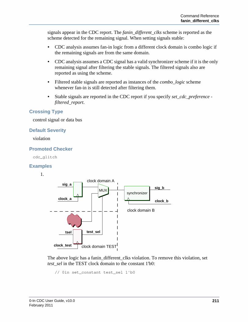
Command Referencefanin_different_clks
0-In CDC User Guide, v10.0 211February 2011
signals appear in the CDC report. The fanin_different_clks scheme is reported as thescheme detected for the remaining signal. When setting signals stable:
• CDC analysis assumes fan-in logic from a different clock domain is combo logic ifthe remaining signals are from the same domain.
• CDC analysis assumes a CDC signal has a valid synchronizer scheme if it is the onlyremaining signal after filtering the stable signals. The filtered signals also arereported as using the scheme.
• Filtered stable signals are reported as instances of the combo_logic schemewhenever fan-in is still detected after filtering them.
• Stable signals are reported in the CDC report if you specify set_cdc_preference -filtered_report.
Crossing Type
control signal or data bus
Default Severity
violation
Promoted Checker
cdc_glitch
Examples
1.
The above logic has a fanin_different_clks violation. To remove this violation, settest_sel in the TEST clock domain to the constant 1'b0:
// 0in set_constant test_sel 1'b0
clock_b
clock domain A
clock domain B
clock_a
sig_asig_b
synchronizer
clock domain TESTclock_test
tsel test_sel
MUX

0-In CDC User Guide, v10.0212
Command Referencefanin_different_clks
February 2011
2. Following is an example of reporting for fan-in logic from different clock domains:
Violations (1)-------------------------------------------Fan-in logic from different clock domain (1)
===========================================Fan-in logic from different clock domain-------------------------------------------clk3: end: u1.q(t8.v: 30)
clk1: start: u0.q(t8.v: 30)via: u0.qvia: u1.d
clk2: u5.q(t8.v: 30)via: u5.qvia: u1.d
3. Fanin logic from 2 clock domains:
always @ (posedge tx1_clk)tx1_sig <= in1;
always @ (posedge tx2_clk)tx2_sig <= in2;
always @ (posedge rx_clk) beginsync0 <= tx1_sig | tx2_sig;sync1 <= sync0;
end
Fanin logic from multiple clock domains. (fanin_different_clks)-----------------------------------------------------------------rx_clk : end : s0 (fanin_different_clks.v : 9)(ID:fanin_different_clks_84638) tx1_clk : start : tx1_sig (fanin_different_clks.v : 8) tx2_clk : start : tx2_sig (fanin_different_clks.v : 8)
rx_clktx1_clk
tx1_sig sync1
DFF DFF
sync0
tx2_clk
tx2_sig
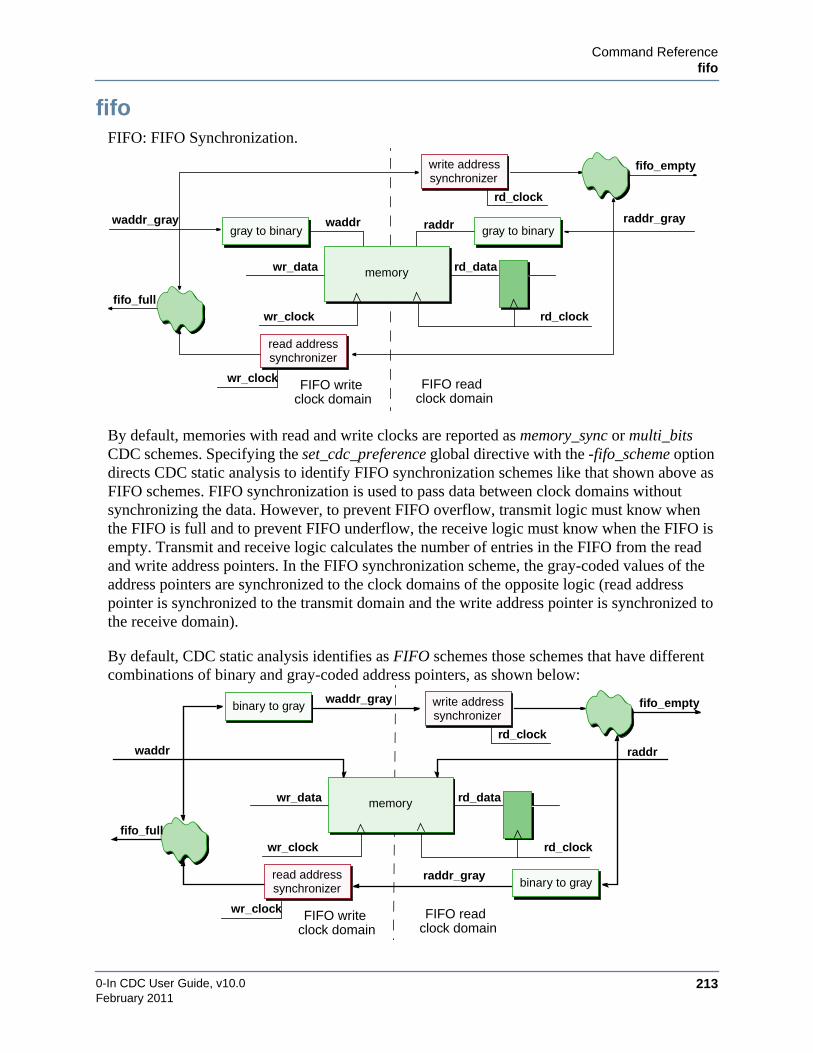
Command Referencefifo
0-In CDC User Guide, v10.0 213February 2011
fifoFIFO: FIFO Synchronization.
By default, memories with read and write clocks are reported as memory_sync or multi_bitsCDC schemes. Specifying the set_cdc_preference global directive with the -fifo_scheme optiondirects CDC static analysis to identify FIFO synchronization schemes like that shown above asFIFO schemes. FIFO synchronization is used to pass data between clock domains withoutsynchronizing the data. However, to prevent FIFO overflow, transmit logic must know whenthe FIFO is full and to prevent FIFO underflow, the receive logic must know when the FIFO isempty. Transmit and receive logic calculates the number of entries in the FIFO from the readand write address pointers. In the FIFO synchronization scheme, the gray-coded values of theaddress pointers are synchronized to the clock domains of the opposite logic (read addresspointer is synchronized to the transmit domain and the write address pointer is synchronized tothe receive domain).
By default, CDC static analysis identifies as FIFO schemes those schemes that have differentcombinations of binary and gray-coded address pointers, as shown below:
FIFO read
rd_datamemory
FIFO writeclock domain clock domain
wr_clock
write address
gray to binarygray to binary
wr_data
raddrwaddr
synchronizer
read addresssynchronizer
wr_clock
rd_clock
waddr_gray
fifo_full
fifo_empty
raddr_gray
rd_clock
FIFO read
rd_datamemory
FIFO writeclock domain clock domain
wr_clock
write address
wr_data
synchronizer
read addresssynchronizer
wr_clock
rd_clockwaddr
fifo_full
fifo_empty
raddr
rd_clock
binary to gray
binary to gray
raddr_gray
waddr_gray

0-In CDC User Guide, v10.0214
Command Referencefifo
February 2011
The templates CDC static analysis uses to detect FIFO schemes can be adjusted using theset_cdc_fifo_preference global variable (see page 267).
The memories used in the FIFO schemes can be multidimensional arrays but they must bemodeled as abstract memories (see “set_memory” on page 308). The memories also can bespecified using register/latch files (see “set_cdc_fifo” on page 266).
Crossing Type
data bus
Default Severity
evaluation
Promoted Checkers
• No checker is promoted for the FIFO protocol.
• A cdc_hamming_distance_one checker is promoted for each address synchronizer.
Examples
1. Following is an example to turn severity to caution:
// 0in set_cdc_preference -fifo_scheme// 0in set_cdc_report –scheme fifo –severity caution
2. In the following CDC report entry, the two synchronizers are the read and the writepointer synchronizers:
Cautions=================================================================FIFO synchronization. (fifo)-----------------------------------------------------------------sys_clk : start : inst_m1dsi_al_0.crs_async_fifo_0.data_q
(/ASIC/lib/src/async_fifo_rtl.vhd : 34)tx_byte_hs_clk : end inst_m1dsi_al_0.crs_async_fifo_0.data2_q
(/ASIC/lib/src/async_fifo_rtl.vhd : 37) (ID:fifo_85752) Read Synchronizer ID : bus_two_dff_48297 Write Synchronizer ID : bus_two_dff_55880

Command Referencefifo
0-In CDC User Guide, v10.0 215February 2011
3. RAM-based FIFO synchronizer. CDC analysis only recognizes this instance as a fifoscheme if set_cdc_preference -fifo_scheme is specified.
Also, the clock domains of the address pointers are identified explicitly:
// 0in set_cdc_port_domain wr_addr -clock wr_clk// 0in set_cdc_port_domain rd_addr -clock rd_clk
reg [2:0] wr_sync1, wr_sync2,reg [2:0] rd_sync1, rd_sync2;reg [2:0] Mem [7:0];
always @(posedge wr_clk) beginMem [wr_addr] <= wr_data;rd_sync1 <= rd_addr ;rd_sync2 <= rd_sync1;full <=((wr_addr+1)==rd_sync2)?1:0;
end
always @(posedge rd_clk) beginrd_data <= Mem [rd_addr];wr_sync1 <= wr_addr;wr_sync2 <= wr_sync1;empty <=(rd_addr == wr_sync2)? 1:0;
end
Evaluations=================================================================FIFO synchronization. (fifo)-----------------------------------------------------------------wr_clk : start : Mem (fifo1.v : 11) (ID:fifo_10640) rd_clk : end : rd_data (fifo1.v : 6) Read pointer synchronizer ID : bus_two_dff_18726 Write pointer synchronizer ID : bus_two_dff_646
Multiple-bit signal synchronized by DFF synchronizer. (bus_two_dff)-----------------------------------------------------------------rd_clk : start : rd_addr (fifo1.v : 5) wr_clk : end : rd_sync1 (fifo1.v : 10) (ID:bus_two_dff_18726)wr_clk : start : wr_addr (fifo1.v : 5) rd_clk : end : wr_sync1 (fifo1.v : 10) (ID:bus_two_dff_646)
wr_addr memory
rd_clk
wr_data
rd_sync1
rd_data
rd_addr
rd_sync2
wr_sync1 wr_sync2 empty
full
wr_clk

0-In CDC User Guide, v10.0216
Command Referencefifo
February 2011
4. Register-file based FIFO synchronizer. CDC analysis only recognizes this instance as afifo scheme if set_cdc_preference -fifo_scheme is specified. Also, to detect the registerfile:
// 0in set_cdc_fifo Mem1 Mem2 Mem3 Mem4
reg [2:0] wr_sync1, wr_sync2,reg [2:0] rd_sync1, rd_sync2;
always @(posedge wr_clk) begincase (wr_addr)3’d0: Mem1[0] <= wr_data;3’d1: Mem1[1] <= wr_data;3’d2: Mem2[0] <= wr_data;3’d3: Mem2[1] <= wr_data;3’d4: Mem3[0] <= wr_data;3’d5: Mem3[1] <= wr_data;3’d6: Mem4[0] <= wr_data;3’d7: Mem4[1] <= wr_data;
endcaserd_sync1 <= rd_addr ;rd_sync2 <= rd_sync1;full <=((wr_addr+1)==rd_sync2)?1:0;
end
always @(posedge rd_clk) begincase (rd_addr)3’d0: rd_data <= Mem1[0];3’d1: rd_data <= Mem1[1];3’d2: rd_data <= Mem2[0];3’d3: rd_data <= Mem2[1];3’d4: rd_data <= Mem3[0];3’d5: rd_data <= Mem3[1];3’d6: rd_data <= Mem4[0];3’d7: rd_data <= Mem4[1];
endcasewr_sync1 <= wr_addr;wr_sync2 <= wr_sync1;empty <=(rd_addr == wr_sync2)? 1:0;
end
Evaluations=================================================================FIFO synchronization. (fifo)-----------------------------------------------------------------wr_clk : start : Mem1[0] (fifo2.v : 11) (ID:fifo_47408) rd_clk : end : rd_data (fifo2.v : 6) Read pointer synchronizer ID : bus_two_dff_18726 Write pointer synchronizer ID : bus_two_dff_646
wr_clk : start : Mem1[1] (fifo2.v : 11) (ID:fifo_47412) rd_clk : end : rd_data (fifo2.v : 6) Read pointer synchronizer ID : bus_two_dff_18726 Write pointer synchronizer ID : bus_two_dff_646
wr_clk : start : Mem2[0] (fifo2.v : 12) (ID:fifo_12944) rd_clk : end : rd_data (fifo2.v : 6) Read pointer synchronizer ID : bus_two_dff_18726 Write pointer synchronizer ID : bus_two_dff_646
wr_addr memory
rd_clk
wr_data
rd_sync1
rd_data
rd_addr
rd_sync2
wr_sync1 wr_sync2 empty
full
wr_clk
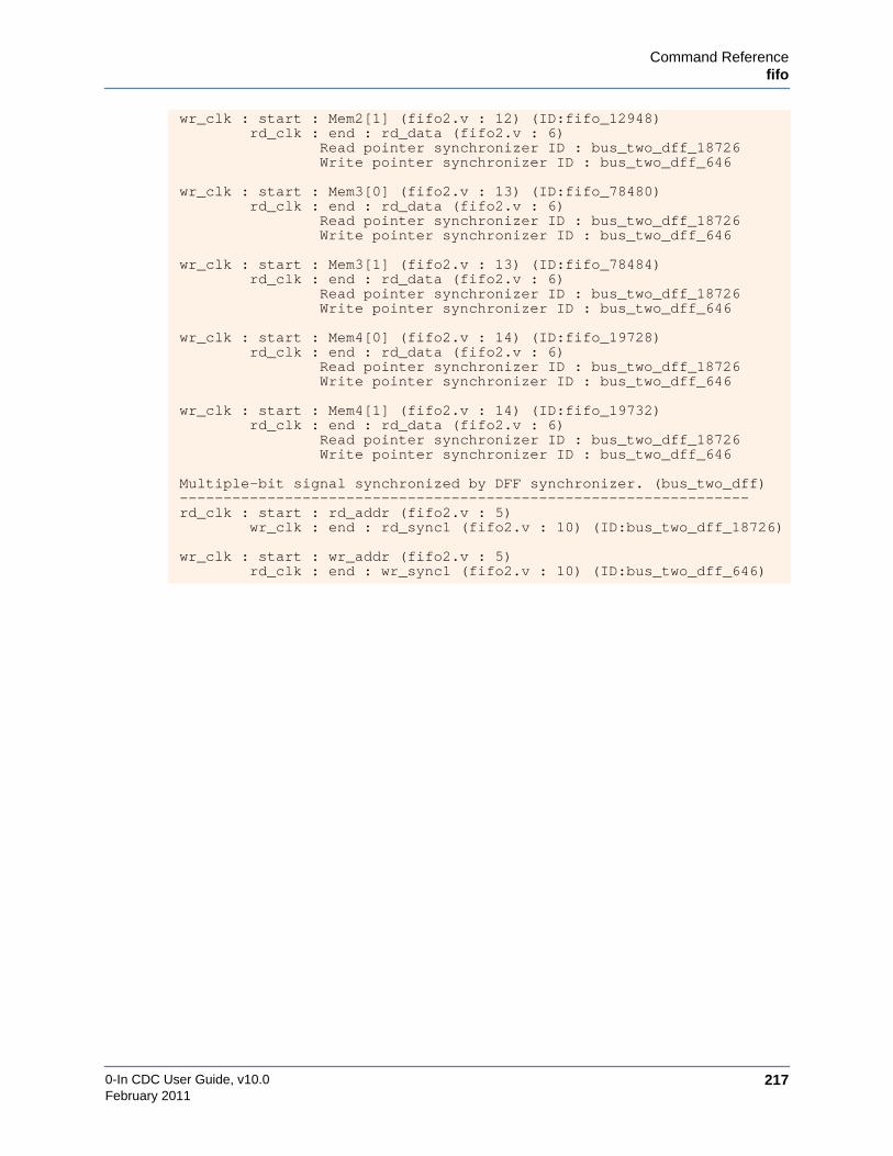
Command Referencefifo
0-In CDC User Guide, v10.0 217February 2011
wr_clk : start : Mem2[1] (fifo2.v : 12) (ID:fifo_12948) rd_clk : end : rd_data (fifo2.v : 6) Read pointer synchronizer ID : bus_two_dff_18726 Write pointer synchronizer ID : bus_two_dff_646
wr_clk : start : Mem3[0] (fifo2.v : 13) (ID:fifo_78480) rd_clk : end : rd_data (fifo2.v : 6) Read pointer synchronizer ID : bus_two_dff_18726 Write pointer synchronizer ID : bus_two_dff_646
wr_clk : start : Mem3[1] (fifo2.v : 13) (ID:fifo_78484) rd_clk : end : rd_data (fifo2.v : 6) Read pointer synchronizer ID : bus_two_dff_18726 Write pointer synchronizer ID : bus_two_dff_646
wr_clk : start : Mem4[0] (fifo2.v : 14) (ID:fifo_19728) rd_clk : end : rd_data (fifo2.v : 6) Read pointer synchronizer ID : bus_two_dff_18726 Write pointer synchronizer ID : bus_two_dff_646
wr_clk : start : Mem4[1] (fifo2.v : 14) (ID:fifo_19732) rd_clk : end : rd_data (fifo2.v : 6) Read pointer synchronizer ID : bus_two_dff_18726 Write pointer synchronizer ID : bus_two_dff_646
Multiple-bit signal synchronized by DFF synchronizer. (bus_two_dff)-----------------------------------------------------------------rd_clk : start : rd_addr (fifo2.v : 5) wr_clk : end : rd_sync1 (fifo2.v : 10) (ID:bus_two_dff_18726)
wr_clk : start : wr_addr (fifo2.v : 5) rd_clk : end : wr_sync1 (fifo2.v : 10) (ID:bus_two_dff_646)

0-In CDC User Guide, v10.0218
Command Referencefour_latch
February 2011
four_latchFOUR LATCH SYNCHRONIZER: Single-bit signal synchronized by latch synchronizer.
Synchronization using four latches is a standard method of synchronizing a 1-bit signal. Theend Rx signal for the synchronizer is the first latch in the synchronizer.
Crossing Type
1-bit signal
Default Severity
evaluation
Promoted Checker
cdc_sync
Examples
1. Following is an example to turn severity to caution:
// 0in set_cdc_report -scheme four_latch -severity caution
2. Following is an example to turn off promotion:
// 0in set_cdc_report –scheme four_latch -promotion off
3. Example promoted transfer protocol checker for four_latch synchronization scheme:
/* 0in cdc_sync-tx_var mtr.fifo_rd -tx_clock pci_clk-name cdc_sync_0 -module cpu_top-inferred */
4. Four-latch synchronizer:
always @ (*)if (rx_clk) beginsync1 <= tx_sig;// 1st latchsync3 <= sync2; // 3rd latch
endelse beginsync2 <= sync1; // 2nd latchrx_sig <= sync3;// 4th latch
end
rx_clk
Tx Clock Domain Rx Clock Domain
tx_clk
tx_sig rx_siglatch latch latch latch
rx_clktx_clk
tx_sig rx_sig
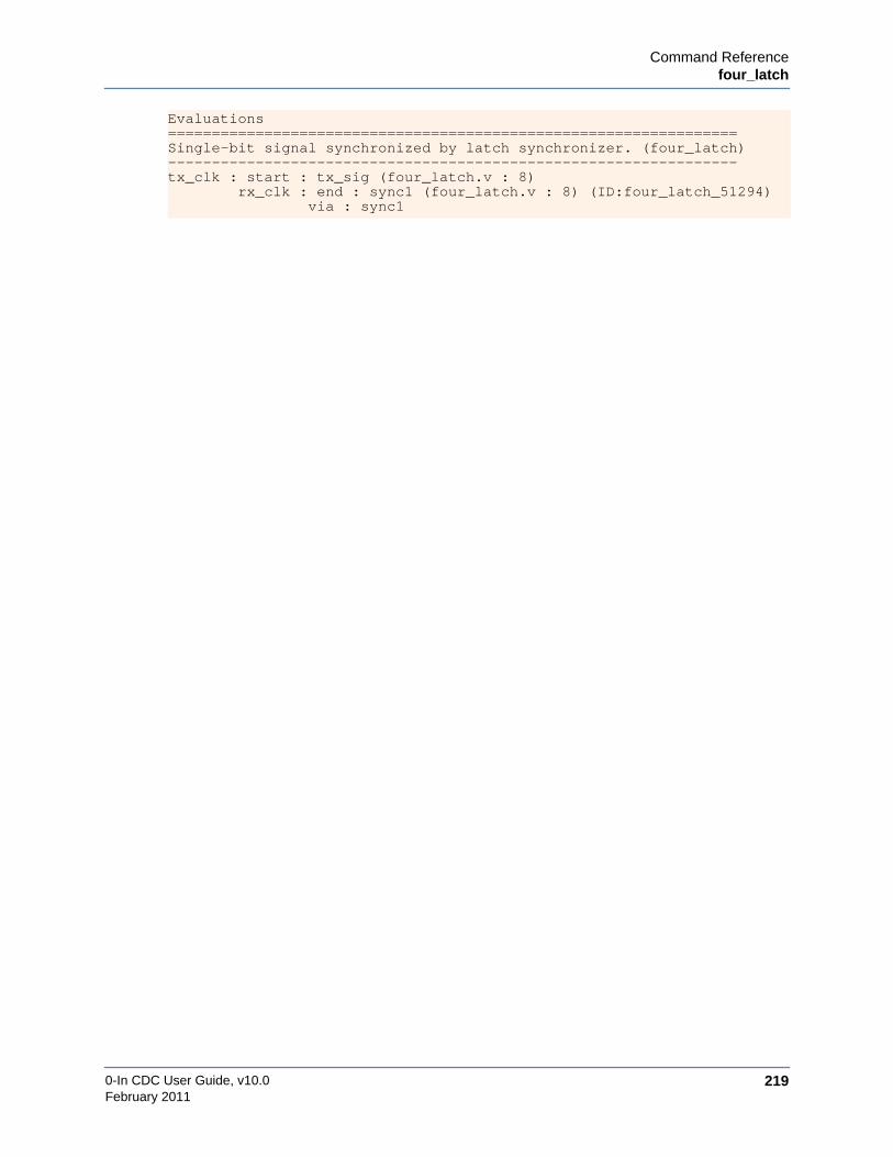
Command Referencefour_latch
0-In CDC User Guide, v10.0 219February 2011
Evaluations=================================================================Single-bit signal synchronized by latch synchronizer. (four_latch)-----------------------------------------------------------------tx_clk : start : tx_sig (four_latch.v : 8) rx_clk : end : sync1 (four_latch.v : 8) (ID:four_latch_51294) via : sync1

0-In CDC User Guide, v10.0220
Command Referencehandshake
February 2011
handshakeHANDSHAKE: Handshake synchronization.
Specifying the set_cdc_preference global directive with the -handshake_scheme option directsCDC static analysis to identify DMUX synchronization schemes like that shown above asHANDSHAKE CDC schemes. Like DMUX synchronization, handshake synchronization uses asynchronized select signal to enable a data MUX to pass through data to the receive clockdomain. Handshake synchronization has additional synchronization of the receive data MUXselect signal back to the transmit clock domain as feedback into the select logic. This “round-trip” synchronizer circuit automatically resets the receive domain MUX select signal. Theenable signal to the transmit data MUX select also activates the receive data MUX select via theround-trip synchronizer.
Crossing Type
data bus
Default Severity
evaluation
Promoted Checkers
• No checker is promoted for the handshake protocol.
• A cdc_dsel checker is promoted for the DMUX synchronization.
• Two cdc_sync checkers are promoted for the round-trip synchronizer.
Promoted CDC-FX Checker
cdc_fx check is on by default.
rx_clk
Tx Clock Domain Rx Clock Domain
acknowledge synchronizer request synchronizer
MUX recirculation
tx_clk
SRC FSM
DEST FSM
handshake loop
ack-tx path en

Command Referencehandshake
0-In CDC User Guide, v10.0 221February 2011
Examples
1. Following is an example to turn severity to caution:
// 0in set_cdc_preference -handshake_scheme// 0in set_cdc_report -scheme handshake -severity caution
2. In the following CDC report entry, the two synchronizers are the two 2DFFsynchronizers in the round-trip synchronizer circuit.
Cautions=================================================================Handshake synchronization. (handshake)-----------------------------------------------------------------ClkO : start : DMUXInLtch (Sync_ReqAck.v: 107)
ClkR : end : DMUXOutLtch (Sync_ReqAck.v: 114)(ID:handshake_21466)Synchronizer ID : two_dff_17913Synchronizer ID : pulse_sync_28075
Request Signal: ReqInOAcknowledge Signal: AckIn
3. Following example shows an instance of a handshake scheme. This scheme is a specialcase of a DMUX scheme and by default, is reported as such. To turn on HANDSHAKEreporting:
// 0in set_cdc_preference -handshake_scheme
The following code implements handshake synchronization:
// transmit data registeralways @ (posedge tx_clk)
if (enable & ack_synced) tx_data <= din;
// receive data registeralways @ (posedge rx_clk)
if (ack) rx_data <= tx_data;
// generate requestalways @ (posedge tx_clk) req <= (req | enable) & !ack_synced;
// generate acknowledgealways @ (posedge rx_clk) ack <= req_synced;
// acknowledge synchronizer in TX domainalways @ (posedge tx_clk) begin: ACK_SYNC
reg temp;temp <= ack;ack_synced <= temp;
end
// request synchronizer in RX domainalways @ (posedge rx_clk) begin: REQ_SYNC reg temp; temp <= req; req_synced <= temp;end

0-In CDC User Guide, v10.0222
Command Referencehandshake
February 2011
Handshake synchronization. (handshake)-----------------------------------------------------------------tx_clk : start : tx_data (handshake.v : 11)
rx_clk : end : rx_data (handshake.v : 11) (ID:handshake_7492) Synchronizer ID : two_dff_24576 Synchronizer ID : two_dff_36232 Request Signal: req Acknowledge Signal: ack
enable
din rx_data
rx_clktx_clk data flow
en en
ack_synced
req_synced
ack
tx_data
req

Command Referencememory_sync
0-In CDC User Guide, v10.0 223February 2011
memory_syncMEMORY SYNC: Memory Synchronization.
CDC synchronization using a 2D array (for example, a memory element used as a FIFO) is astandard method of synchronizing CDC signals or data buses. CDC analysis detects CDCcrossings to and from memory, but the analysis cannot verify proper synchronizationconfiguration and does not promote a transfer protocol checker to verify proper synchronizationoperation.
Crossing Type
control signal or data bus
Default Severity
caution
Promoted Checker
none
Examples
1. Following is an example to turn severity to caution:
// 0in set_cdc_report –scheme memory_sync –severity caution
2. Following is an example to turn off reporting:
// 0in set_cdc_report –scheme memory_sync –severity off
3. Fanin logic from 2 clock domains:
always @(posedge wr_clk)Mem [wr_addr] <= wr_data;
always @(posedge rd_clk)rd_data <= Mem [rd_addr];
Memory Synchronization. (memory_sync)-----------------------------------------------------------------wr_clk: start: Mem (memory_sync.v : 9)
rd_clk: end: rd_data (memory_sync.v: 6) (ID:memory_sync_69262)
rd_clk
Rd Clock Domain
rd_data
memory
Wr Clock Domain
rd_clk
rd_dataMem
wr_clk
wr_data
wr_addr rd_addr
0-In CDC User Guide, v10.0224
Command Referencememory_sync
February 2011
Potential Problem
The CDC compiler currently does not perform read/write analysis, and misses the conditionwhere the read and write addresses are equal, which could result in unreported memorywrite-through errors. Adding checkers to guard against this condition is suggested. Thecompiler issues a warning (hdl–105) whenever it finds an instance of a memory_sync scheme.

Command Referencemulti_bits
0-In CDC User Guide, v10.0 225February 2011
multi_bitsMULTIPLE BITS: Multiple-bit signal across clock domain boundary.
An unsynchronized CDC data bus in most cases should be a static violation. Similarly, a CDCdata bus synchronized using a 2DFF synchronizer should not drive any logic from the wireconnecting the two flip-flops. However, some data buses from test or configuration logic mightbe constant or ad hoc synchronous with the receive clock domain. Similarly, test orconfiguration logic driven by the wire connecting the two flip-flops of a 2DFF synchronizermight also be constant or ad hoc synchronous with the receive clock domain. The severity ofthese crossing schemes are typically set to caution.
Crossing Type
multibit data bus
Default Severity
violation
Promoted Checker
cdc_sample
Promoted CDC-FX Checker
cdc_fx check is on by default.
Examples
1. Following is an example to turn reporting off for the status_test signal in module dut:
/* 0in set_cdc_report -scheme multi_bits -from status_test-severity off -module dut */
rx_clk
Tx Clock Domain Rx Clock Domain
tx_clk
tx_data rx_datamissing
synchronizer
rx_clk
Tx Clock Domain Rx Clock Domain
tx_clk
tx_data rx_dataDFF DFF
additional logicdriven by signal
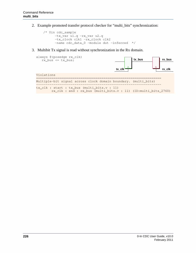
0-In CDC User Guide, v10.0226
Command Referencemulti_bits
February 2011
2. Example promoted transfer protocol checker for “multi_bits” synchronization:
/* 0in cdc_sample-tx_var u1.q -rx_var u2.q-tx_clock clk1 -rx_clock clk2-name cdc_data_0 -module dut -inferred */
3. Multibit Tx signal is read without synchronization in the Rx domain.
always @(posedge rx_clk)rx_bus <= tx_bus;
Violations=================================================================Multiple-bit signal across clock domain boundary. (multi_bits)-----------------------------------------------------------------tx_clk : start : tx_bus (multi_bits.v : 11) rx_clk : end : rx_bus (multi_bits.v : 11) (ID:multi_bits_2760)
rx_clktx_clk
tx_bus rx_bus

Command Referencemulti_sync_mux_select
0-In CDC User Guide, v10.0 227February 2011
multi_sync_mux_selectMULTIPLE SYNCHRONIZERS AT DMUX: MUX select fan-in contains more than onesynchronizer.
In most cases, if a MUX select is used to synchronize a signal or data bus, then the MUX selectfan-in should not have more than one synchronizer. However, some synchronization schemesare tolerant of this type of synchronization scheme. In this case, the two synchronizersreconverge at the MUX select. So, a reconvergence scheme is reported in addition to themulti_sync_mux_select scheme.
Crossing Type
control signal or data bus
Default Severity
caution
Promoted Checker
cdc_sample
Promoted CDC-FX Checker
cdc_fx check is on by default.
Examples
1. Following is an example to turn severity to evaluation:
/* 0in set_cdc_report -scheme multi_sync_mux_select-severity evaluation */
2. Following is an example to turn off promotion:
/* 0in set_cdc_report -scheme multi_sync_mux_select-severity evaluation -promotion off */
tx_data rx_data
rx_clk
Tx Clock Domain Rx Clock Domain
tx_clk
tx_sel1
rx_sel
tx_sel2
DFF DFF
DFFDFF
MUX DFF

0-In CDC User Guide, v10.0228
Command Referencemulti_sync_mux_select
February 2011
3. DMUX synchronizer with multiple control signals synchronized in the Rx domain:
always @(posedge rx_clk) beginreg s1_sel1, s2_sel1;reg [1:0] s_sel2;s1_sel1 <= tx_sel1;s2_sel1 <= s1_sel1;s_sel1 <= {s_sel2[0], tx_sel2};if (s_sel2[1] | s2_sel1)rx_data <= tx_data;
end
Cautions=================================================================Mux select fanin contains more than one synchronizer.(multi_sync_mux_select)-----------------------------------------------------------------tx_clk: start: tx_data (test31.v: 9)
rx_clk: end: rx_data (test31.v: 6)(ID:multi_sync_mux_select_53401) Synchronizer ID : shift_reg_41011 Synchronizer ID : two_dff_93371
tx_data
rx_data
rx_clktx_clk
tx_sel1
tx_sel2
DFF DFF
MUX
s1_sel1 s2_sel1
shift register
s_sel2[1]

Command Referenceno_sync
0-In CDC User Guide, v10.0 229February 2011
no_syncMISSING SYNCHRONIZER: Single-bit signal does not have proper synchronizer.
An unsynchronized CDC signal is typically a static violation, but if such a crossing terminatesat a black box module or RAM, the default severity is reported as caution (becausesynchronization might occur in the black box). Similarly, a CDC signal synchronized using a2DFF synchronizer that drives logic from the wire connecting the two flip-flops is reported as astatic violation by default.
Some signals from test or configuration logic might be constant or ad hoc synchronous with thereceive clock domain. Also, test or configuration logic driven by the wire connecting the twoflip-flops of a 2DFF synchronizer might also be constant or ad hoc synchronous with thereceive clock domain. The severity of these crossing schemes are typically set to caution.
Crossing Type
1-bit signal
Default Severity
violation or caution
Promoted Checker
cdc_sample
Promoted CDC-FX Checker
cdc_fx check is on by default.
Examples
1. Following is an example to turn severity to caution for the write_test signal in themodule dut:
/* 0in set_cdc_report -scheme no_sync -from write_test
rx_clk
Tx Clock Domain Rx Clock Domain
tx_clk
tx_sig rx_sigmissing
synchronizer
rx_clk
Tx Clock Domain Rx Clock Domain
tx_clk
tx_sig rx_sigDFF DFF
additional logicdriven by signal

0-In CDC User Guide, v10.0230
Command Referenceno_sync
February 2011
-severity caution -module dut */
2. Example promoted transfer protocol checker for “no_sync” synchronization:
/* 0in cdc_sample-tx_var u1.q -rx_var u2.q-tx_clock clk1 -rx_clock clk2-name cdc_data_0 -module dut -inferred */
3. Tx signal is read without synchronization in the Rx domain.
always @(posedge rx_clk, posedge rst)if (rst)rx_sig <= 1’b1;
elserx_sig <= tx_sig;
Violations=================================================================Single-bit signal does not have proper synchronizer. (no_sync)-----------------------------------------------------------------tx_clk : start : tx_sig (no_sync.v : 9) rx_clk : end : rx_sig (no_sync.v : 9) (ID:no_sync_59042)
rx_clktx_clk
tx_sig rx_sig

Command Referenceport_constraint_mismatch
0-In CDC User Guide, v10.0 231February 2011
port_constraint_mismatchPORT CONSTRAINT MISMATCH: Signal connected to a port of a custom synchronizer is ina clock domain that is not allowed by the custom synchronizer’s port constraints.
A CDC port constraint identifies all clock domains allowed for signals connected to instances ofthe port. A port constraint is specified using the set_cdc_port_constraint directive. Currentlyport constraints are supported only for design units that are custom synchronizers (i.e.,identified with the set_cdc_synchronizer custom directive).
Custom Synchronizer
For a standard custom synchronizer, you can specify a CDC port constraint on any of its signaland data bus input ports. The constraint can specify allowed clock domains for signalsconnected to it, allowed clock domains for the signal that clocks the port, or both. You also canspecify allowed pairs of clock domains for instances of the port: one for the signal connected tothe port and one for signal that clocks the port. A constrained port of an instance of the designunit has a port constraint mismatch if one of the following holds:
• The signal connected to the port is not from an allowed transmit clock domain for theport.
• The signal clocking the port is not from an allowed receive clock domain for the port.
• The domain of the transmit signal and the domain of the receive clock signal are not anallowed clock domain pair for the port.
Custom Synchronizer with Crossing
For a custom synchronizer with crossing, you can specify CDC port constraints on its signal anddata bus ports. These identify the allowed clock domains for signals connected to them.
rx_clk
Tx Clock Domain Rx Clock Domain
tx_clk
tx_sig rx_sigcustom
synchronizerportconstraint
illegal Rx clock domain for port
illegal Tx clock domain for port
Tx Clock Domain Rx Clock Domain
rx_clktx_clk
tx_sig rx_sigcustom synchronizer
with crossingportconstraint
portconstraint
illegal Tx clockdomain for port
illegal Rx clockdomain for port
0-In CDC User Guide, v10.0232
Command Referenceport_constraint_mismatch
February 2011
Crossing Type
control signal or data bus
Default Severity
violation
Promoted Checker
none
Examples
1. Following is an example to turn severity to evaluation for port constraint mismatches forcustom synchronizers in module prk:
/* 0in set_cdc_report -scheme port_constraint_mismatch-from write_test-severity evaluation -module prk */

Command Referencepulse_sync
0-In CDC User Guide, v10.0 233February 2011
pulse_syncPULSE SYNC: Pulse Synchronization.
Pulse synchronization is a standard method of synchronizing a 1-bit signal. A variation of thisscheme happens if the pulse output is delayed. Specify the set_cdc_preference -delayed_pulsedirective to recognize such schemes as pulse_sync schemes.
Crossing Type
1-bit signal
Default Severity
evaluation
Promoted Checker
cdc_sync
Examples
1. Following is an example to turn severity to caution:
// 0in set_cdc_report –scheme pulse_sync –severity caution
2. Following is an example to turn off promotion:
/* 0in set_cdc_report –scheme pulse_sync–severity caution–promotion off */
3. Example promoted transfer protocol checker for “two_dff” synchronization scheme:
/* 0in cdc_sync-tx_var isyncabus.stage1_q -tx_clock clk1-tx_min `P_clk1_clk2_tx_min -name cdc_sync_0-module test -inferred */
rx_clk
Tx Clock Domain Rx Clock Domain
tx_clk
rx_sig
DFF DFF DFFtx_sig
rx_clk
Tx Clock Domain Rx Clock Domain
tx_clk
rx_sig
DFF DFF DFFtx_sig
DFF

0-In CDC User Guide, v10.0234
Command Referencepulse_sync
February 2011
4. Standard pulse synchronizer:
5. Pulse synchronizer with delay. To detect this type of synchronizer, specify:
// 0in set_cdc_preference -delayed_pulse
reg p0, p1, p2, pulse;always @ (posedge rx_clk) begin
p0 <= tx_sig; // 1st flopp1 <= p0; // 2nd flopp2 <= p1; // 3rd flop
endalways @ * pulse <= p1 ^ p2;
Evaluations=================================================================Pulse Synchronization. (pulse_sync)-----------------------------------------------------------------tx_clk: start: tx_sig (pulse_sync.v : 8)
rx_clk: end: PULSE_SYNC.p0 (pulse_sync.v :16)(ID:pulse_sync_1845)
reg p0, p1, p2, pulse, dpulse;always @ (posedge rx_clk) begin
p0 <= tx_sig; // 1st flopp1 <= p0; // 2nd flopp2 <= p1; // 3rd flopdpulse <= pulse;// 4th flop
endalways @ * pulse <= p1 ^ p2;
Evaluations=================================================================Pulse Synchronization. (pulse_sync)-----------------------------------------------------------------tx_clk: start: tx_sig (pulse_sync.v : 8)
rx_clk: end: PULSE_SYNC.p0 (pulse_sync.v :16)(ID:pulse_sync_1845)
rx_clktx_clk
pulsetx_sig
rx_clktx_clk
pulsetx_sig
dpulse

Command Referencereconvergence
0-In CDC User Guide, v10.0 235February 2011
reconvergenceRECONVERGENCE: Reconvergence of synchronizers.
Reconvergence occurs when the fan-in of a flip-flop includes two separately synchronized CDCsignals from a different clock domain. The synchronizers can be any of the following:bus_dff_sync_gated_clk, bus_four_latch, bus_shift_reg, bus_two_dff, bus_two_dff_phase ortwo_dff_phase, dff_sync_gated_clk, four_latch. shift_reg, two_dff, pulse_sync and custom.
Reconvergence of two signals might result in synchronization problems. When multiple bitsreconverge, their relative timing is unpredictable. Logic that receives these signals shouldaccount for potential cycle skew—for example, by using a hamming encoding scheme forsignals in the receiving domain. For signals that have large guard times between changes, thisencoding happens naturally.
If it is not feasible to either design receiving logic that accounts for the potential cycle skew orencode the signals, then you should group the signals and transfer them as a group using asynchronized MUX enable (as used for multiple-bit data signals). To force CDC analysis torecognize reconvergence schemes that start from a dmux, simple_dmux ormulti_sync_mux_select scheme, specify set_cdc_preference -dmux_as_recon_start (page 283).
Crossing Type
multiple control signals or data buses
Default Severity
caution
Promoted Checker
cdc_hamming1 (if enabled, see “set_cdc_preference” on page 283).
tx/rx_clk
sig1 tx_sig1
reconverging signals
Source Clock Domains Tx/Rx Clock Domain
sig2 tx_sig2
rx_sig
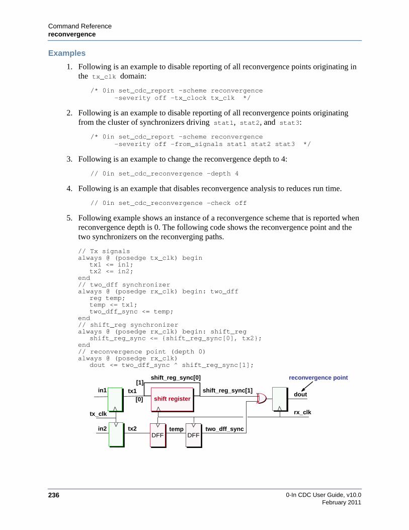
0-In CDC User Guide, v10.0236
Command Referencereconvergence
February 2011
Examples
1. Following is an example to disable reporting of all reconvergence points originating inthe tx_clk domain:
/* 0in set_cdc_report -scheme reconvergence-severity off -tx_clock tx_clk */
2. Following is an example to disable reporting of all reconvergence points originatingfrom the cluster of synchronizers driving stat1, stat2, and stat3:
/* 0in set_cdc_report -scheme reconvergence-severity off -from_signals stat1 stat2 stat3 */
3. Following is an example to change the reconvergence depth to 4:
// 0in set_cdc_reconvergence -depth 4
4. Following is an example that disables reconvergence analysis to reduces run time.
// 0in set_cdc_reconvergence -check off
5. Following example shows an instance of a reconvergence scheme that is reported whenreconvergence depth is 0. The following code shows the reconvergence point and thetwo synchronizers on the reconverging paths.
// Tx signalsalways @ (posedge tx_clk) begin
tx1 <= in1;tx2 <= in2;
end// two_dff synchronizeralways @ (posedge rx_clk) begin: two_dff
reg temp;temp <= tx1;two_dff_sync <= temp;
end// shift_reg synchronizeralways @ (posedge rx_clk) begin: shift_reg
shift_reg_sync <= {shift_reg_sync[0], tx2};end// reconvergence point (depth 0)always @ (posedge rx_clk)
dout <= two_dff_sync ^ shift_reg_sync[1];
DFF DFF
rx_clktx_clk
doutshift_reg_sync[1]
shift registertx1
shift_reg_sync[0]
[0]
[1]
two_dff_sync
reconvergence point
in1
in2 tx2 temp
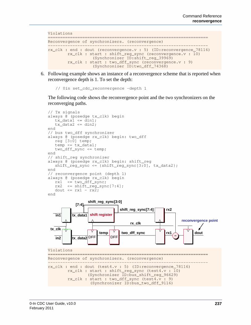
Command Referencereconvergence
0-In CDC User Guide, v10.0 237February 2011
6. Following example shows an instance of a reconvergence scheme that is reported whenreconvergence depth is 1. To set the depth:
// 0in set_cdc_reconvergence -depth 1
The following code shows the reconvergence point and the two synchronizers on thereconverging paths.
Violations=================================================================Reconvergence of synchronizers. (reconvergence)-----------------------------------------------------------------rx_clk : end : dout (reconvergence.v : 5) (ID:reconvergence_78116) rx_clk : start : shift_reg_sync (reconvergence.v : 10)
(Synchronizer ID:shift_reg_39969) rx_clk : start : two_dff_sync (reconvergence.v : 9)
(Synchronizer ID:two_dff_74368)
// Tx signalsalways @ (posedge tx_clk) begin
tx_data1 <= din1;tx_data2 <= din2;
end// bus two_dff synchronizeralways @ (posedge rx_clk) begin: two_dff
reg [3:0] temp;temp <= tx_data1;two_dff_sync <= temp;
end// shift_reg synchronizeralways @ (posedge rx_clk) begin: shift_reg
shift_reg_sync <= {shift_reg_sync[3:0], tx_data2};end// reconvergence point (depth 1)always @ (posedge rx_clk) begin
rx1 <= two_dff_sync;rx2 <= shift_reg_sync[7:4];dout <= rx1 - rx2;
end
Violations=================================================================Reconvergence of synchronizers. (reconvergence)-----------------------------------------------------------------rx_clk : end : dout (test4.v : 5) (ID:reconvergence_78116) rx_clk : start : shift_reg_sync (test4.v : 10)
(Synchronizer ID:bus_shift_reg_96629) rx_clk : start : two_dff_sync (test4.v : 9)
(Synchronizer ID:bus_two_dff_9116)
DFF DFF
rx_clk
tx_clkdout
shift_reg_sync[7:4]shift registertx_data1
shift_reg_sync[3:0][7:4]
two_dff_sync
reconvergence pointin1
in2 tx_data2temp
–rx1
rx2

0-In CDC User Guide, v10.0238
Command Referenceredundant
February 2011
redundantREDUNDANT: Redundant synchronization.
Redundant synchronizers are multiple synchronizers in the same clock domain that synchronizethe same CDC signal. The values of the rx_sig1 and rx_sig2 signals might not match, because ofmetastability. If these separately synchronized signals are in the fan-in of the same flip-flop,then a reconvergence problem might exist. But, even if they are not, redundant synchronizerscreate extra logic that can be eliminated by splitting the signals after they are synchronized.
Crossing Type
multiple control signals or data buses
Default Severity
caution
Promoted Checker
none
Example
1. Following is an example to disable reporting of redundant synchronizers on *_en signalsfrom the tx_clk domain:
/* 0in set_cdc_report -scheme redundant-severity off -from *_en -tx_clock tx_clk */
rx_clk
tx_clk
tx_sig
rx_sig1
Tx Clock Domain Rx Clock Domain
rx_sig2
synchronizer
synchronizer
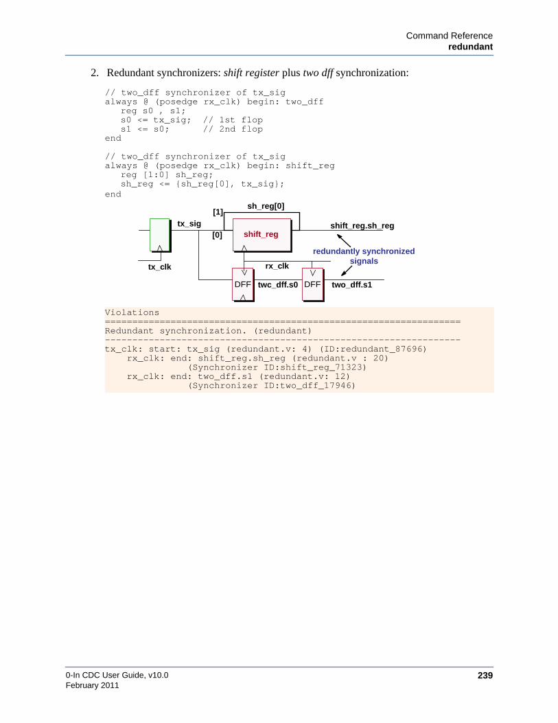
Command Referenceredundant
0-In CDC User Guide, v10.0 239February 2011
2. Redundant synchronizers: shift register plus two dff synchronization:
// two_dff synchronizer of tx_sigalways @ (posedge rx_clk) begin: two_dff
reg s0 , s1;s0 <= tx_sig; // 1st flops1 <= s0; // 2nd flop
end
// two_dff synchronizer of tx_sigalways @ (posedge rx_clk) begin: shift_reg
reg [1:0] sh_reg;sh_reg <= {sh_reg[0], tx_sig};
end
Violations=================================================================Redundant synchronization. (redundant)-----------------------------------------------------------------tx_clk: start: tx_sig (redundant.v: 4) (ID:redundant_87696)
rx_clk: end: shift_reg.sh_reg (redundant.v : 20)(Synchronizer ID:shift_reg_71323)
rx_clk: end: two_dff.s1 (redundant.v: 12)(Synchronizer ID:two_dff_17946)
tx_clk
shift_reg.sh_regshift_reg
tx_sig
sh_reg[0]
[0]
[1]
redundantly synchronized
rx_clk
two_dff.s1DFF DFFtwc_dff.s0
signals

0-In CDC User Guide, v10.0240
Command Referenceseries_redundant
February 2011
series_redundantSERIES REDUNDANT: Custom synchronizers connected in series.
Series redundant synchronizers are custom synchronizers connected in series, whichsynchronize to the same clock domain or do not have a specified clock domain. To determine iftwo custom synchronizers in series are in the same domain, the clock domain of the output ofthe Tx synchronizer is matched with the clock domain of the input of the Rx synchronizer. CDCanalysis does not report custom synchronizers in series as series redundant if one of thesynchronizers’ ports is specified as asynchronous. However, series redundant synchronizers arereported even if they are not used in a clock domain crossing.
Series-redundant synchronizers do not indicate CDC problems, but they do indicate a waste oflogic and power consumption.
Crossing Type
multiple control signals or data buses
Default Severity
caution
Promoted Checker
none
Examples
1. Following is an example to disable reporting of series redundant synchronizers on *_en
signals from the tx_clk domain:
/* 0in set_cdc_report -scheme series_redundant-severity off -from *_en -tx_clock tx_clk */
rx_clktx_clk
tx_sig
Tx Clock Domain Rx Clock Domain
rx_sigcustom
synchronizercustom
synchronizer
Tx synchronizer Rx synchronizer

Command Referenceseries_redundant
0-In CDC User Guide, v10.0 241February 2011
2. Custom synchronizers connected in a redundant series
custom_sync #(4)cust_sync_A(
.clk (rx_clk),
.d (tx_data),
.q (cust_sync_A_out));custom_sync #(4)
cust_sync_B(.clk (rx_clk),.d (cust_sync_A_out),.q (cust_sync_B_out));
Series Redundant synchronization. (series_redundant)-----------------------------------------------------------------rx_clk: start: custom_sync_A.q (series_redundant.v : 27)
rx_clk: end: custom_sync_B.d (series_redundant.v : 29)(ID:series_redundant_93597)
rx_clktx_clk
tx_data cust_sync_B_out
cust_sync_A cust_sync_B
cust_sync_A_out

0-In CDC User Guide, v10.0242
Command Referenceshift_reg
February 2011
shift_regSHIFT REG: Shift-register synchronization.
Synchronization using a shift register is a standard method of synchronizing a 1-bit signal. It isequivalent to synchronization with two or more in-phase flip-flops. The difference is in thecoding templates recognized by the two schemes. The following example shows the code for ashift register synchronization scheme:
reg [n:0] shftregalways @(clock) shftreg <= {shftreg[n-1:0],din};
Crossing Type
1-bit signal
Default Severity
evaluation
Promoted Checker
cdc_sync
Examples
1. Following is an example to turn severity to caution:
// 0in set_cdc_report –scheme shift_reg –severity caution
2. Following is an example to turn off promotion:
/* 0in set_cdc_report –scheme shift_reg–severity caution –promotion off */
3. Example promoted transfer protocol checker for “shift_reg” synchronization scheme:
/* 0in cdc_sync-tx_var u0.q -tx_clock clk1-tx_min `P_clk1_clk2_tx_min-name cdc_sync_0 -module dut -inferred */
rx_clktx_clk
tx_sig rx_sig
Tx Clock Domain Rx Clock Domain
shift register
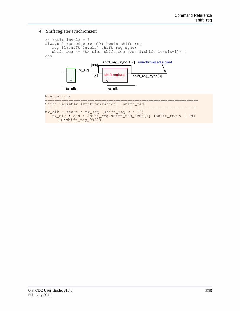
Command Referenceshift_reg
0-In CDC User Guide, v10.0 243February 2011
4. Shift register synchronizer:
// shift_levels = 8always @ (posedge rx_clk) begin shift_reg
reg [1:shift_levels] shift_reg_sync;shift_reg <= {tx_sig, shift_reg_sync[1:shift_levels-1]} ;
end
Evaluations=================================================================Shift-register synchronization. (shift_reg)-----------------------------------------------------------------tx_clk : start : tx_sig (shift_reg.v : 10)
rx_clk : end : shift_reg.shift_reg_sync[1] (shift_reg.v : 19)(ID:shift_reg_99229)
tx_clk
shift_reg_sync[8]shift registertx_sig
shift_reg_sync[1:7]
[7]
[0:6]synchronized signal
rx_clk

0-In CDC User Guide, v10.0244
Command Referencesimple_dmux
February 2011
simple_dmuxSIMPLE_DMUX: Simple MUX enable.
The simple DMUX scheme is a restricted version of the general DMUX scheme. For thegeneral scheme, the fanin logic of the Rx signal can contain any logic and the synchronizedcontrol signal can use any logic to turn off the Tx signal (not just a MUX). The control signalcan be synchronized by any of the following signal synchronizers: bus_dff_sync_gated_clk,bus_four_latch, bus_shift_reg, bus_two_dff, bus_two_dff_phase or two_dff_phase,dff_sync_gated_clk, four_latch. shift_reg, two_dff, pulse_sync and custom.
The simple DMUX scheme has the following restrictions:
• Logic between the Tx and Rx signals has a MUX.
• Rx output feeds back to the MUX input.
• Tx signal drives the D-input of the Rx register
• Tx and Rx drivers are registers.
• No combo logic is between the Tx and Rx registers.
• No combo logic is between select output from the synchronizer and the MUX.
NoteThe physical design of the MUX logic (that controls the path from the Tx register to theRx registers) must not allow glitches at the input to an Rx register when the Tx registerchanges value.
Crossing Type
synchronized control signal and muxed data bus
Default Severity
caution
tx_clk
tx_data rx_data
rx_clk
Tx Clock Domain Rx Clock Domain
tx_clk
tx_selrx_selDFFDFF
MUX

Command Referencesimple_dmux
0-In CDC User Guide, v10.0 245February 2011
Promoted Checker
cdc_dsel
Promoted CDC-FX Checker
cdc_fx check is on by default.
Examples
1. Following is an example to turn severity to evaluation:
// 0in set_cdc_report -scheme simple_dmux -severity evaluation
2. Following is an example to turn off promotion:
/* 0in set_cdc_report -scheme simple_dmux-severity evaluation -promotion off */
3. Example promoted transfer protocol checker for simple_dmux synchronization scheme:
/* 0in cdc_dsel-tx_data isyncdbus.data_reg -tx_clock clk1-rx_clock clk2 -tx_data_select 1'b0-rx_data_select (isyncdbus.stage3_q ^ isyncdbus.isync.out)-tx_min `P_clk1_clk2_tx_min-name cdc_dsel_1 -module test -inferred */
4. Bus synchronized by a simple DMUX synchronizer:
always @(posedge rx_clk)begin: DMUX
reg s1, rx_sel;s1 <= tx_sel; // 1st DFFrx_sel <= s1; // 2nd DFFif (rx_sel)rx_data <= tx_data;
end
Cautions=================================================================Simple DMUX synchronization. (simple_dmux)-----------------------------------------------------------------tx_clk : start : tx_data (simple_dmux.v : 9)
rx_clk : end : rx_data (simple_dmux.v : 6) (ID:simple_dmux_44768) Synchronizer ID : two_dff_44468
tx_clk
tx_datarx_data
rx_clk
tx_selrx_selDFFDFF
MUX
s1

0-In CDC User Guide, v10.0246
Command Referencesingle_source_reconvergence
February 2011
single_source_reconvergenceSSR: Single-source reconvergence of synchronizers.
Reconvergence occurs when the fan-in of a flip-flop includes two separately synchronized CDCsignals from a different clock domain. Single-source reconvergence is the special case wherereconverging signals in the receive domain originate from the same signal in the transmitdomain. Reconvergent signals might result in synchronization problems, but large designs canhave large numbers of reconvergence paths. Single-source reconvergence paths are more likelyto cause design problems than reconvergence paths from unrelated sources, so they can be givena higher priority when resolving issues of reconvergence.
Static CDC analysis reports single-source reconvergence paths as both reconvergence violationsand SSR violations. The set_cdc_reconvergence (page 291) global directive adjusts twoparameters used to determine how extensive static CDC analysis of reconvergence paths shouldbe:
• depth
Maximum number of sequential levels in the receive domain from the synchronizers tothe reconverging paths. The depth is used to limit analysis of reconverging paths (bothsingle-source and separate-source).
• divergence depth
Maximum number of sequential levels in the transmit domain from the flip-flops drivingthe synchronizers backwards to the single source. The depth is used to limit analysis ofsingle-source reconverging paths.
By default, instances of single-source reconvergence are reported only as instances of thereconvergence scheme. Specifying set_cdc_reconvergence -divergence_depth <depth> enablesSSR reporting for matching divergence/reconvergence paths.
Crossing Type
multiple control signals or data buses
tx/rx_clk
reconverging signals
Source Clock Domain Tx/Rx Clock Domain
clk
single source

Command Referencesingle_source_reconvergence
0-In CDC User Guide, v10.0 247February 2011
Default Severity
violation
Promoted Checker
cdc_hamming1 (if enabled, see “set_cdc_preference” on page 283).
Examples
1. Following is an example to disable reporting of single-source reconvergence pointsoriginating in the tx_clk domain:
/* 0in set_cdc_report -scheme single_source_reconvergence-severity off -tx_clock tx_clk */
2. Following is an example to disable reporting of single-source reconvergence pointsoriginating from the cluster of synchronizers driving stat1, stat2, and stat3:
/* 0in set_cdc_report -scheme single_source_reconvergence-severity off -from_signals stat1 stat2 stat3 */
3. Following is an example to change the reconvergence depth to 4 and enable single-source reconvergence reporting with a divergence depth of 5:
// 0in set_cdc_reconvergence -depth 4 -divergence_depth 5
4. Following examples change the reconvergence depth and and enable single-sourcereconvergence reporting:
// 0in set_cdc_reconvergence -depth 1 -divergence_depth 2
depth = 1
Tx Clock Domain Rx Clock Domain
synchronizer
synchronizer
synchronizer
divergence depth = 2
reported single-sourcereconvergence paths

0-In CDC User Guide, v10.0248
Command Referencesingle_source_reconvergence
February 2011
// 0in set_cdc_reconvergence -depth 2 -divergence_depth 1
5. Following example shows an instance of a single-source reconvergence scheme that isreported when divergence depth is 0. SSR reporting is off by default, so turn on SSRreporting:
// 0in set_cdc_reconvergence -divergence_depth 0
The following code shows the divergence and reconvergence points and the twosynchronizers on the reconverging paths.
// divergence pointalways @ (posedge tx_clk)
ctrl <= ci0 | ci1 ;
// two_dff synchronizeralways @ (posedge rx_clk) begin: two_dff
reg temp;temp <= ctrl;two_dff_sync <= temp;
end
// shift_reg synchronizeralways @ (posedge rx_clk) begin: shift_reg
shift_reg_sync <= {shift_reg_sync[0], ctrl};end
// reconvergence pointalways @ (posedge rx_clk)
dout <= two_dff_sync ^ shift_reg_sync[1];
depth = 2
Tx Clock Domain Rx Clock Domain
synchronizer
synchronizer
synchronizer
divergencedepth = 1
reported single-sourcereconvergence paths
DFF DFF
rx_clktx_clk
doutshift_reg_sync[1]
shift registerctrl
shift_reg_sync[0]
[0]
[1]
two_dff_sync
divergence point
divergence depth = 0
reconvergence point

Command Referencesingle_source_reconvergence
0-In CDC User Guide, v10.0 249February 2011
6. Following example shows an instance of a single-source reconvergence scheme that isreported when divergence depth is 1. SSR reporting is off by default, so turn on SSRreporting:
// 0in set_cdc_reconvergence -divergence_depth 1
The following code shows the divergence and reconvergence points and the twosynchronizers on the reconverging paths.
Single Source Reconvergence of synchronizers.(single_source_reconvergence)-----------------------------------------------------------------rx_clk : end : dout (single_source_reconvergence.v : 5)
(ID:single_source_reconvergence_41397)rx_clk: start: shift_reg_sync(single_source_reconvergence.v : 10)(Synchronizer ID:shift_reg_97221)
rx_clk : start : two_dff_sync (single_source_reconvergence.v : 9)(Synchronizer ID:two_dff_44733)
tx_clk : diverge : ctrl (single_source_reconvergence.v : 8)
// divergence pointalways @ (posedge tx_clk) begin
diverge <= diverge + 1; // 1 level to synctx_data1 <= din + diverge; // 0 levels to synctx_data2 <= ~diverge; // 0 levels to sync
end
// two_dff synchronizeralways @ (posedge rx_clk) begin: two_dff
reg [3:0] temp;temp <= tx_data1;two_dff_sync <= temp;
end
// bus_shift_reg synchronizeralways @ (posedge rx_clk) begin: shift_reg
shift_reg_sync <= {shift_reg_sync[3:0], tx_data2};end
// reconvergence pointalways @ ( posedge rx_clk )
dout <= two_dff_sync - shift_reg_sync[7:4];
DFF DFF
rx_clktx_clk
doutshift_reg_sync[7:4]
bus shift
shift_reg_sync[3:0][7:4]
two_dff_sync
divergence point
divergence depth = 1
reconvergence point
+
–diverge
dintx_data1
tx_data2[3:0]
register

0-In CDC User Guide, v10.0250
Command Referencesingle_source_reconvergence
February 2011
Single Source Reconvergence of synchronizers.(single_source_reconvergence)-----------------------------------------------------------------rx_clk : end : dout (single_source_reconvergence.v : 5)
(ID:single_source_reconvergence_84301)rx_clk: start: shift_reg_sync (single_source_reconvergence.v : 10)(Synchronizer ID:bus_shift_reg_96629)
rx_clk : start : two_dff_sync (single_source_reconvergence.v : 9)(Synchronizer ID:bus_two_dff_9116)
tx_clk : diverge : diverge (single_source_reconvergence.v : 8)
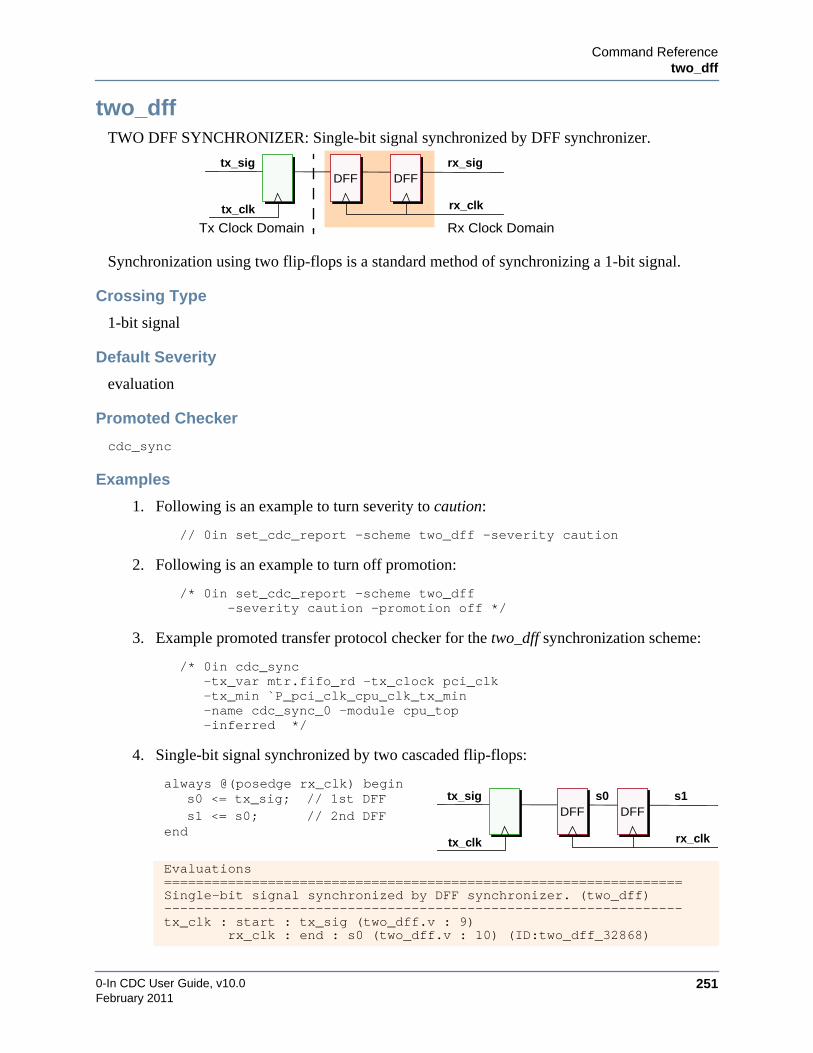
Command Referencetwo_dff
0-In CDC User Guide, v10.0 251February 2011
two_dffTWO DFF SYNCHRONIZER: Single-bit signal synchronized by DFF synchronizer.
Synchronization using two flip-flops is a standard method of synchronizing a 1-bit signal.
Crossing Type
1-bit signal
Default Severity
evaluation
Promoted Checker
cdc_sync
Examples
1. Following is an example to turn severity to caution:
// 0in set_cdc_report –scheme two_dff –severity caution
2. Following is an example to turn off promotion:
/* 0in set_cdc_report –scheme two_dff–severity caution –promotion off */
3. Example promoted transfer protocol checker for the two_dff synchronization scheme:
/* 0in cdc_sync-tx_var mtr.fifo_rd -tx_clock pci_clk-tx_min `P_pci_clk_cpu_clk_tx_min-name cdc_sync_0 -module cpu_top-inferred */
4. Single-bit signal synchronized by two cascaded flip-flops:
always @(posedge rx_clk) begins0 <= tx_sig; // 1st DFFs1 <= s0; // 2nd DFF
end
Evaluations=================================================================Single-bit signal synchronized by DFF synchronizer. (two_dff)-----------------------------------------------------------------tx_clk : start : tx_sig (two_dff.v : 9) rx_clk : end : s0 (two_dff.v : 10) (ID:two_dff_32868)
rx_clk
Tx Clock Domain Rx Clock Domaintx_clk
tx_sig rx_sigDFF DFF
rx_clktx_clk
tx_sig s1DFF DFF
s0

0-In CDC User Guide, v10.0252
Command Referencetwo_dff
February 2011
5. Single-bit signal synchronized by two cascaded flip-flops with enable ports:
// 0in set_cdc_preference -allow_enable_in_sync
Notes
If you use a DFF synchronization scheme that has more than two flip-flops, then you can getCDC analysis to recognize the scheme by specifying a set_cdc_synchronizer directive(page 302). For example, the following CDC global directive identifies 4 DFF synchronizers asvalid “two_dff” schemes for CDC paths from the tx_clk domain to the rx_clk domain:
/* 0in set_cdc_synchronizer dff -level 4-tx_clock tx_clk -rx_clock rx_clk */
always @(posedge rx_clk)if (enable){s0, s1} <= {tx_sig, s0};
Evaluations=================================================================Single-bit signal synchronized by DFF synchronizer. (two_dff)-----------------------------------------------------------------tx_clk : start : tx_sig (two_dff.v : 9) rx_clk : end : s0 (two_dff.v : 10) (ID:two_dff_32868)
rx_clktx_clk
tx_sigs1
EN EN
s0
enable
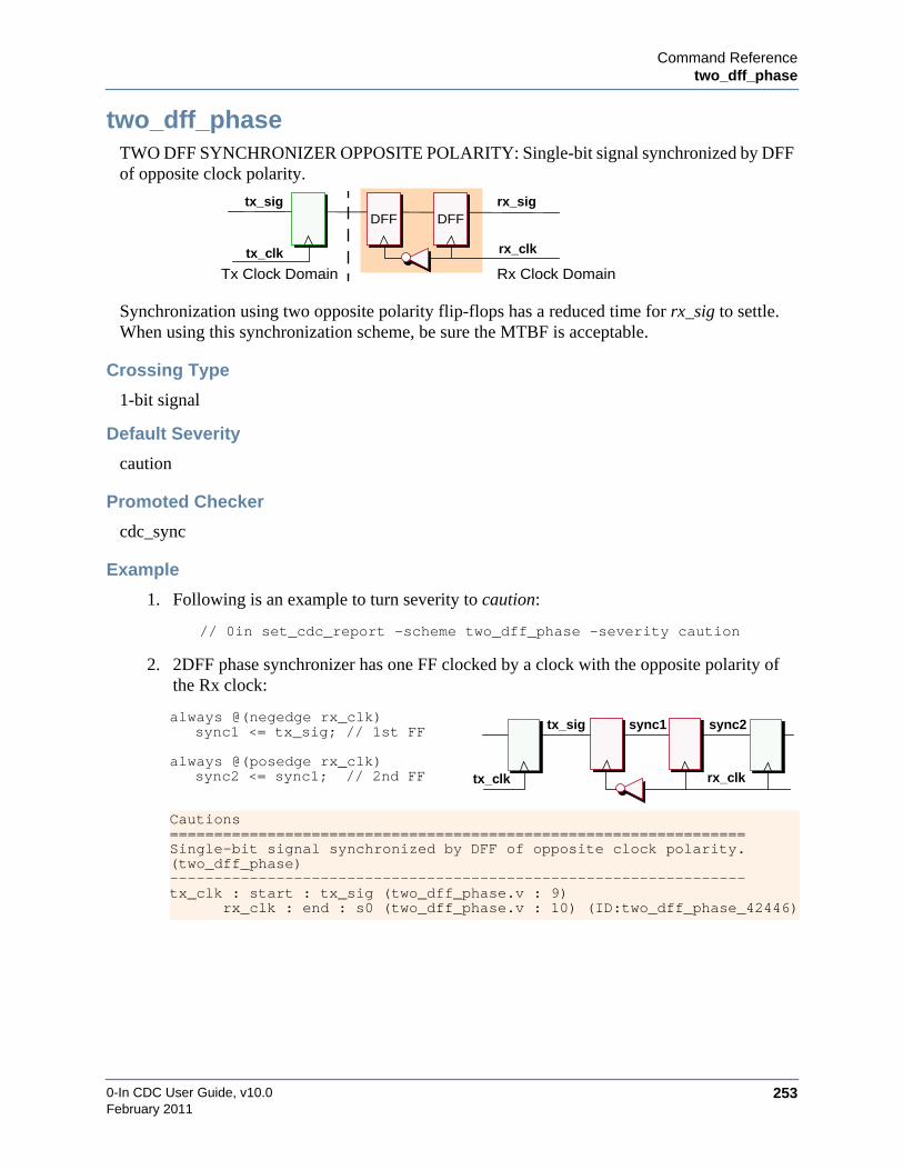
Command Referencetwo_dff_phase
0-In CDC User Guide, v10.0 253February 2011
two_dff_phaseTWO DFF SYNCHRONIZER OPPOSITE POLARITY: Single-bit signal synchronized by DFFof opposite clock polarity.
Synchronization using two opposite polarity flip-flops has a reduced time for rx_sig to settle.When using this synchronization scheme, be sure the MTBF is acceptable.
Crossing Type
1-bit signal
Default Severity
caution
Promoted Checker
cdc_sync
Example
1. Following is an example to turn severity to caution:
// 0in set_cdc_report -scheme two_dff_phase -severity caution
2. 2DFF phase synchronizer has one FF clocked by a clock with the opposite polarity ofthe Rx clock:
always @(negedge rx_clk)sync1 <= tx_sig; // 1st FF
always @(posedge rx_clk)sync2 <= sync1; // 2nd FF
Cautions=================================================================Single-bit signal synchronized by DFF of opposite clock polarity.(two_dff_phase)-----------------------------------------------------------------tx_clk : start : tx_sig (two_dff_phase.v : 9)
rx_clk : end : s0 (two_dff_phase.v : 10) (ID:two_dff_phase_42446)
rx_clk
Tx Clock Domain Rx Clock Domaintx_clk
tx_sig rx_sigDFF DFF
tx_clk
tx_sig
rx_clk
sync1 sync2

0-In CDC User Guide, v10.0254
Command ReferenceGlobal Directives
February 2011
Global DirectivesGlobal directives configure and control the 0-In verification tools. This section has descriptionsof the use of primitives and wildcards in global directives, followed by data sheets for the globaldirectives.
0-In CommentsTo use global directives, you place them inside 0-In comments in control files. A control file is atext file containing a Verilog module or VHDL design unit.
NoteGlobal directives specified outside a Verilog module or VHDL design unit areignored.
0-In comments have a similar structure as generic HDL comments, but start with the identifier0in. You can include multiple directives in the same 0-In comment, if you separate them bysemicolons. Everything within a 0-In comment is meaningful to the 0-In compilers. Thecontents are interpreted as one or more directives. You cannot include a 0-In comment inside anHDL comment.
The 0-In compilers read two types of 0-In comments:
• Single-line 0-In comments
Verilog single-line 0-In comments begin with // 0in. VHDL single-line 0-In commentsbegin with -- 0in. Single-line 0-In comments are effective to the end of the line. You caninclude a single-line HDL comment inside a single-line 0-In comment.
// 0in set_black_box modX // Black-box modX module
-- 0in set_black_box entityX -- Black-box entityX entity
• Block 0-In comments
Verilog block 0-In comments begin with /* 0in and are effective until the terminator */.VHDL block 0-In comments start each line with -- 0in. A new line in a block 0-Incomment is treated as whitespace. Both the 0in keyword and the global directive namemust be specified on the first line of a block 0-In comment. You cannot include HDLcomments inside block 0-In comments. For example:
/* 0in set_cdc_report -scheme blackbox-from out2a -to bb1.* -severity off */
-- 0in set_cdc_report -scheme blackbox-- 0in -from out2a -to bb1.* -severity off

Command ReferenceGlobal Directives
0-In CDC User Guide, v10.0 255February 2011
0-In PrimitivesExpressions in 0-In directives are HDL expressions that can include 0-In primitives.Expressions represent signals derived from other signals or expressions that evaluate to signals.0-In primitives can refer to signals or expressions that evaluate to signals, including otherprimitives. Expressions can combine HDL expressions and 0-In primitives using HDLoperators and parentheses for grouping. 0-In primitives are expressions. Expressions indirectives must be enclosed in parentheses. The 0-In primitives are: $0in_rising_edge,$0in_falling_edge, $0in_0_to_1, $0in_1_to_0, $0in_delay, and $0in_spy. The$0in_rising_edge and $0in_falling_edge primitives use Verilog posedge/negedge semantics,which accounts for transitions involving X. The $0in_0_to_1 and $0in_1_to_0 primitives do notaccount for transitions involving X.
$0in_0_to_1(expression [,clock])
$0in_1_to_0(expression [,clock])
$0in_rising_edge(expression [,clock])
Signal that asserts when expressiontransitions from 0 to 1. The signalde-asserts when expression de-asserts or at the active edge of theclock, whichever comes first.
Signal that asserts when expressiontransitions from 1 to 0. The signalde-asserts when expression assertsor at the active edge of the clock,whichever comes first.
Signal that asserts when expressiontransitions from 0 to 1/X or from Xto 1. The signal de-asserts whenexpression transitions again or atthe active edge of the clock,whichever comes first.
clock
sig
($0in_0_to_1(sig, clock))
clock
sig
($0in_1_t0_0(sig, clock))
clock
sig_b
($0in_rising_edge(sig_b, clock))
sig_a
($0in_rising_edge(sig_a, clock))
sig_c
($0in_rising_edge(sig_c, clock))

0-In CDC User Guide, v10.0256
Command ReferenceGlobal Directives
February 2011
$0in_falling_edge(expression [,clock])
$0in_delay(expression [, number_of_cycles [,clock]])
$0in_spy(name [, number])
Using $0in_spy simplifies the file list, which can reduce the runtime and memory footprint.This primitive allows specifying hierarchical names that might be outside of the file list given tothe compiler. The representation is a signal whose name is name and whose bit-width is number(default 1). The compiler does not try to resolve this signal in the file list, and prints it out "as is"in the checker logic.
For example,
// 0in set_reset -default $0in_spy(top.rst)
Assumes that top.rst signal is 1 bit and hooks up to the resets of checkers, even if top is notgiven in the filelist. Compare this with the following:
// 0in set_reset -default top.rst
This results in a warning/error with an unresolved signal on top.rst if the module top is notgiven in the filelist. Following is another example:
// 0in one_hot -var $0in_spy(tb.u0.a.b.c, 8) -clock clk
Signal that asserts when expressiontransitions from 1 to 0/X or from Xto 0. The signal de-asserts whenexpression transitions again or atthe active edge of the clock,whichever comes first.
Signal derived from the signalspecified by expression, delayed bythe specified number of clockcycles. The default clock is inferredfrom expression if it is possible.Otherwise, the clock is inferredfrom the directive.
clock
sig_b
($0in_falling_edge(sig_b, clock))
sig_a
($0in_falling_edge(sig_a, clock))
sig_c
($0in_falling_edge(sig_c, clock))
sig
($0in_delay(sig, n, clock))n cycles

Command ReferenceGlobal Directives
0-In CDC User Guide, v10.0 257February 2011
This puts a one_hot checker on an 8-bit tb.u0.a.b.c signal even if the compiler does not find it inthe file list. If tb.u0.a.b.c does not exist or is not 8 bits wide, the simulator generates an error orreports width-mismatch warnings.
The primitive peeks a signed signal into an unsigned vector. For example,
$0in_spy(a.b.c, w);
is mapped to
wire [w-1:0] sg_123 = a.b.c;
Hierarchical PathsDirectives in a control file that do not specify a -module argument (i.e., at the top level) specifysignals with the complete hierarchical paths. Directives in a control file that specify a -moduleargument or set_clock/set_reset directives in a module/architecture (i.e., at a lower level)specify signals relative to the local module/architecture.
Example 1
// G1 is the top level; m1_dut is an instance of M1//0in set_constant G1.F1[0].I0.F2[0].m1_dut.x 1’b1 -module M1
Generates a warning because it specifies an absolute path for x. The directive is skipped.
Example 2
// G1 is the top level; m1_dut is an instance of M1//0in set_constant x 1’b1 -module M1
Matches
G1.F1[0].I0.F2[0].m1_dut.x
Wildcards in Directive ArgumentsWildcards (*) are supported in many global directive arguments. Typically values that supportwildcards are called patterns in the argument descriptions (whereas, values that do not supportwildcards are specified as simply variables, signals or values). In general, signal names andmodule names in global directives support wildcards. Clock group names do not.
Path separators are matches for wildcards (see Example 2).

0-In CDC User Guide, v10.0258
Command ReferenceGlobal Directives
February 2011
Example 1
G1.*.*.F3[0].*.clk* 1’b0
Matches the following specifications. In this example, the bold * matches multiplehierarchical levels.
G1.F1[6].I1.F3[0].m1_dut.clk1G1.F1[6].I1.F3[0].m2_dut.clk2G1.F1[6].I1.F3[0].sync_dut.clk2G1.F1[6].I1.F3[0].sync_dut.dmux_dut.clkG1.F1[6].I1.F3[0].sync_dut.dmux_dut.dff.clk
Example 2
G1.*
Matches all signals below G1 (i.e., any signal with a hierarchy depth > 0 from G1).
Example 3
G1.*.*.*
Matches all signals with a hierarchy depth > 3 from G1, such as:
G1.F1[6].I1.F3[2].m2_dut.int_xG1.F1[6].I1.F3[2].m2_dut.mem_inG1.F1[6].I1.F3[2].sync_dut.bus_in
Example 4
See the CDC Settings Report to see how wildcards are expanded, for example:
*****************************************************************Section D: Wildcard Expansion for Global Directives*****************************************************************Wildcards for set_cdc_port_domain directive-----------------------------------------------------------------File mixed1_ctrl.v : Line 2*in* matches vhdl_inst.in1 vhdl_in v2k_in
Wildcards for set_cdc_signal directive-----------------------------------------------------------------File mixed1_ctrl.v : Line 6vhdl_inst.*c_enum matches vhdl_inst.rec_enum
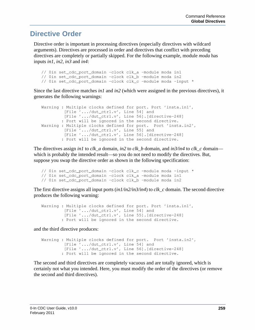
Command ReferenceGlobal Directives
0-In CDC User Guide, v10.0 259February 2011
Directive OrderDirective order is important in processing directives (especially directives with wildcardarguments). Directives are processed in order and directives that conflict with precedingdirectives are completely or partially skipped. For the following example, module moda hasinputs in1, in2, in3 and in4:
// 0in set_cdc_port_domain -clock clk_a -module moda in1// 0in set_cdc_port_domain -clock clk_b -module moda in2// 0in set_cdc_port_domain -clock clk_c -module moda -input *
Since the last directive matches in1 and in2 (which were assigned in the previous directives), itgenerates the following warnings:
Warning : Multiple clocks defined for port. Port ’insta.in1’,[File ’.../dut_ctrl.v’, Line 54] and[File ’.../dut_ctrl.v’, Line 56].[directive-248]
: Port will be ignored in the second directive.Warning : Multiple clocks defined for port. Port ’insta.in2’,
[File ’.../dut_ctrl.v’, Line 55] and[File ’.../dut_ctrl.v’, Line 56].[directive-248]
: Port will be ignored in the second directive.
The directives assign in1 to clk_a domain, in2 to clk_b domain, and in3/in4 to clk_c domain—which is probably the intended result—so you do not need to modify the directives. But,suppose you swap the directive order as shown in the following specification:
// 0in set_cdc_port_domain -clock clk_c -module moda -input *// 0in set_cdc_port_domain -clock clk_a -module moda in1// 0in set_cdc_port_domain -clock clk_b -module moda in2
The first directive assigns all input ports (in1/in2/in3/in4) to clk_c domain. The second directiveproduces the following warning:
Warning : Multiple clocks defined for port. Port ’insta.in1’,[File ’.../dut_ctrl.v’, Line 54] and[File ’.../dut_ctrl.v’, Line 55].[directive-248]
: Port will be ignored in the second directive.
and the third directive produces:
Warning : Multiple clocks defined for port. Port ’insta.in2’,[File ’.../dut_ctrl.v’, Line 54] and[File ’.../dut_ctrl.v’, Line 56].[directive-248]
: Port will be ignored in the second directive.
The second and third directives are completely vacuous and are totally ignored, which iscertainly not what you intended. Here, you must modify the order of the directives (or removethe second and third directives).

0-In CDC User Guide, v10.0260
Command ReferenceDirectives for CDC Analysis
February 2011
Directives for CDC AnalysisTable 6-2 shows the global directives used for static and dynamic CDC analysis. Additionaldirectives used to configure and control assertion logic in simulation and the formal models informal analysis are also relevant to CDC verification. They are described in “Directives forChecker Generation” on page 313.
Table 6-2. Global Directives for CDC Analysis
Type Directive Description Wildcard Args
Clocks andDomains
set_cdc_clock Specifies clocks with theircharacteristics.
clock…-module
set_cdc_port_domain Indicates the specified ports belong toa specified clock domain, areasynchronous to all identified clockdomains or should be ignored.
port…-same_clock-combo_path-module
set_cdc_port_constraint Sets CDC port constraints for designunits identified as customsynchronizers.
module…-ports
CDCAnalysis
set_reset Identifies reset signals or removesthem from the list of inferred signals.
signal…-module
set_cdc_signal Reclassifies the CDC signal type ofspecified CDC signals or addsproperties to specified CDC signals.
signal…-module
set_cdc_preference Sets preferences for CDC staticanalysis.
set_cdc_hier_preference Sets preferences for hierarchical CDCanalysis.
set_mode Sets an operational mode for modalanalysis.
-set signal
set_mode_control Identify legal values for the specifiedmode control signals.
signal…
CDCSchemes
set_cdc_synchronizer Identifies non-standard synchronizertypes and their correspondingproperties.
-clock-module
set_cdc_report Sets the severity level and promotionproperty of matching clock domaincrossings.
-from-through-to-module
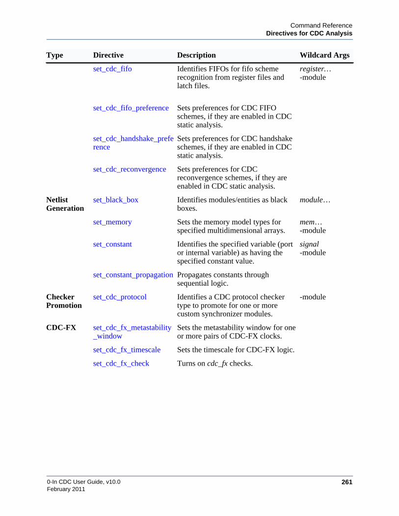
Command ReferenceDirectives for CDC Analysis
0-In CDC User Guide, v10.0 261February 2011
set_cdc_fifo Identifies FIFOs for fifo schemerecognition from register files andlatch files.
register…-module
set_cdc_fifo_preference Sets preferences for CDC FIFOschemes, if they are enabled in CDCstatic analysis.
set_cdc_handshake_preference
Sets preferences for CDC handshakeschemes, if they are enabled in CDCstatic analysis.
set_cdc_reconvergence Sets preferences for CDCreconvergence schemes, if they areenabled in CDC static analysis.
NetlistGeneration
set_black_box Identifies modules/entities as blackboxes.
module…
set_memory Sets the memory model types forspecified multidimensional arrays.
mem…-module
set_constant Identifies the specified variable (portor internal variable) as having thespecified constant value.
signal-module
set_constant_propagation Propagates constants throughsequential logic.
CheckerPromotion
set_cdc_protocol Identifies a CDC protocol checkertype to promote for one or morecustom synchronizer modules.
-module
CDC-FX set_cdc_fx_metastability_window
Sets the metastability window for oneor more pairs of CDC-FX clocks.
set_cdc_fx_timescale Sets the timescale for CDC-FX logic.
set_cdc_fx_check Turns on cdc_fx checks.
Type Directive Description Wildcard Args

0-In CDC User Guide, v10.0262
Command Referenceset_black_box
February 2011
set_black_boxIdentifies modules/entities as black boxes.
Syntax
set_black_box module… [-dont_use_outputs]
• module…
Module/entity names or wildcard patterns.
• -dont_use_outputs
0-In Formal argument ignored for CDC.
Description
The cdc compiler skips netlist elaboration of black-boxed modules/entities and their children.Typically modules/entities declared as user-defined black boxes contain unsupported constructsso the compiler would infer them as black boxes anyway. However, CDC analysis treatsinferred and user-defined black-box modules differently:
• User-defined black box.
• No blackbox schemes are reported for the ports.
• If the clock domain for a port is specified (using a set_cdc_port_domain directive),the port is included in CDC analysis. Otherwise, fanin/fanout logic of the port isignored. No CDC crossing is reported for the port, but a warning is issued.
• Ports asynchronous with the defined clocks should be identified as such using the-async argument.
• Inferred black box.
• A blackbox scheme (with caution severity by default) is reported for each input.
• Each output port is automatically marked as an async port (no set_cdc_port_domainglobal directive is needed). The port is considered a transmit source for a CDCcrossing, so it is reported as the source of a synchronized or unsynchronized path.

Command Referenceset_cdc_clock
0-In CDC User Guide, v10.0 263February 2011
set_cdc_clockSpecifies clocks with their characteristics and redefines the clock domains.
Syntax
set_cdc_clock clock_signal…[[–posedge] [–negedge] [–waveform risingTime fallingTime] [–period value] [–virtual]
[–mode mode] [–group group]| –ignore | –remove][-jitter_percent number] [–module module_pattern]
• clock_signal…
Clock signal names or wildcard patterns. Clock signals can be primary ports or hierarchicalpaths to clock signals. Clock signals can be individual bits of clock vectors.
• -posedge
Clock signals have positive active edges. Default: -posedge.
• -negedge
Clock signals have negative active edges.
• -waveform rising_Time falling_Time
Rising edge and falling edge times (in time units) that define the clock duty cycle. Thisargument is ignored.
• -period value
Clock period in time units. This value is used to calculate directive parameters for promotedcheckers.
• -virtual
Clock signals are virtual clocks used to identify clocks from ports that do not exist in theDUT. For example, specify -virtual for a port associated with a clock that is not an input tothe design.
• -mode mode
Mode for which this directive applies when running modal analysis. The directive is skippedunless you are running CDC modal analysis in the specified mode. Default: directive isrecognized in all modes and for non-modal CDC analysis.
• -group group
Clock group containing the specified clocks. All specified clocks are considered to be in theclock domain corresponding to the group. You can specify multiple set_cdc_clock globaldirectives with the same -group name (for example, to identify clocks in the same domainthat have different clock characteristics). Default: specified clocks are associated with asingle unnamed “default” clock group.

0-In CDC User Guide, v10.0264
Command Referenceset_cdc_clock
February 2011
• -ignore
Add the specified clocks to the list of ignored clocks. Typical usage is to run cdc-report_clock to identify the clocks in the design. Then, use set_cdc_clock -ignore to markspecific clocks to be ignored. Registers in the domains of ignored clocks are not used inCDC analysis. So, marking superfluous clocks as ignored can help improve performance.The 0in_cdc_design.rpt report’s Ignore Clock Tree section lists the clocks marked asignored. If both -ignore and -group are specified, the named clocks are added to thespecified clock group and all clocks in that group are added to the list of ignored clocks.
Default: specified clocks are added to the specified (or default) clock group.
• -remove
Remove clock_signals from the clock tree. Default: specified clocks are added to thespecified (or default) clock group.
• -jitter_percent number
Proportion of the clock cycle that clock edges can jitter. The percent must be <100. Used tocalculate tx_min:
• Default: jitter = 0.
• -module module_pattern
Clock signal names are specified relative to the module matching module_pattern. Ifmultiple modules match module_pattern, then the matching clock_signals in the matchingmodules are grouped in the same clock group. Default: clock signal names are hierarchicalfrom the top level.
Description
Specifies clocks with their characteristics and redefines clock domains. You must specify aclock signal pattern that matches at least one clock signal and no two set_cdc_clock globaldirectives can specify the same clock. Verilog clocks can be bits of multiple-bit variables.VHDL clocks can be scalars (bit, std_logic, std_ulogic) or single-bit vector record elements.
The set_cdc_clock directives without the -module option are processed in the order of entries inthe control file. Then the set_cdc_clock directives with the -module option are processed in theorder of entries in the control file. Wildcard matches do not take precedence over exactmatches.
tx_min int
rx_clk_period 1 jitter100-----------+
×
tx_clk_period 1 jitter100-----------–
×------------------------------------------------------------------( ) 1+=
tx_min int rx_clk_periodtx_clk_period---------------------------------( ) 1+=
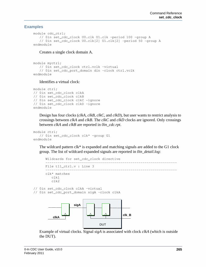
Command Referenceset_cdc_clock
0-In CDC User Guide, v10.0 265February 2011
Examples
module cdc_ctrl;// 0in set_cdc_clock U0.clk U1.clk -period 100 -group A// 0in set_cdc_clock U0.clk[2] U1.clk[2] -period 50 -group A
endmodule
Creates a single clock domain A.
module myctrl;// 0in set_cdc_clock ctrl.vclk -virtual// 0in set_cdc_port_domain din -clock ctrl.vclk
endmodule
Identifies a virtual clock:
module ctrl;// 0in set_cdc_clock clkA// 0in set_cdc_clock clkB// 0in set_cdc_clock clkC -ignore// 0in set_cdc_clock clkD -ignoreendmodule
Design has four clocks (clkA, clkB, clkC, and clkD), but user wants to restrict analysis tocrossings between clkA and clkB. The clkC and clkD clocks are ignored. Only crossingsbetween clkA and clkB are reported in 0in_cdc.rpt.
module ctrl;// 0in set_cdc_clock clk* -group G1
endmodule
The wildcard pattern clk* is expanded and matching signals are added to the G1 clockgroup. The list of wildcard expanded signals are reported in 0in_detail.log:
Wildcards for set_cdc_clock directive-----------------------------------------------------------------File t11_ctrl.v : Line 3-----------------------------------------------------------------clk* matches
clk1clk2
// 0in set_cdc_clock clkA -virtual// 0in set_cdc_port_domain sigA -clock clkA
Example of virtual clocks. Signal sigA is associated with clock clkA (which is outsidethe DUT).
clk_BclkA
sigA
DUT
0-In CDC User Guide, v10.0266
Command Referenceset_cdc_fifo
February 2011
set_cdc_fifoIdentifies FIFOs for fifo scheme recognition from register files and latch files.
Syntax
set_cdc_fiforegister_pattern… [–module module_pattern] [–mode mode]
• register_pattern…
Name pattern for the FIFO registers (or latches).
• –module module_pattern
Name pattern for the modules containing the registers to match. Default: top module.
• –mode mode
Mode to which the FIFO identification belongs. Default: all modes.
Description
Identifies FIFOs defined in register files (or latch files) for analysis of FIFO synchronizationschemes.
Examples
//0in set_cdc_fifo -module reg_file_fifo_* reg*

Command Referenceset_cdc_fifo_preference
0-In CDC User Guide, v10.0 267February 2011
set_cdc_fifo_preferenceSets preferences for FIFO CDC schemes, if they are enabled in CDC static analysis.
Syntax
set_cdc_fifo_preference[-no_write_sync] [-no_read_sync] [-allow_read_flop][-multiple_write_syncs] [-multiple_read_syncs]
• -no_write_sync
Reports as fifo schemes those memory_sync schemes that are FIFO schemes without a writeaddress synchronizer. Default: such schemes are reported as memory_sync schemes.
• -no_read_sync
Reports as fifo schemes those memory_sync schemes that are FIFO schemes without a readaddress synchronizer. Default: such schemes are reported as memory_sync schemes.
• -allow_read_flop
In addition to standard FIFO schemes, reports as fifo schemes those memory_sync schemesthat are FIFO schemes where the read address synchronizer is in the fanout of a read clockdomain register that drives the read address. Default: unless -no_read_sync is specified,only FIFO schemes where the read address synchronizer is in the fanout of the read addressare reported as fifo schemes.
• -multiple_write_syncs
Reports all write address synchronizers and promotes cdc_hamming_distance_one checkersfor them. Default: if the FIFO scheme has multiple write address synchronizers, only one ofthem is reported.
• -multiple_read_syncs
Reports all read address synchronizers and promotes cdc_hamming_distance_one checkersfor them. Default: if the FIFO scheme has multiple read address synchronizers, only one ofthem is reported.
Description
Changes the template used to detect fifo CDC schemes.
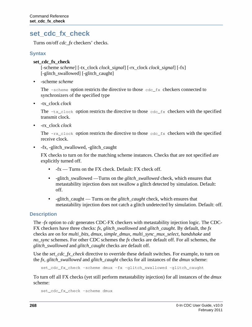
0-In CDC User Guide, v10.0268
Command Referenceset_cdc_fx_check
February 2011
set_cdc_fx_checkTurns on/off cdc_fx checkers’ checks.
Syntax
set_cdc_fx_check[-scheme scheme] [-tx_clock clock_signal] [-rx_clock clock_signal] [-fx][-glitch_swallowed] [-glitch_caught]
• -scheme scheme
The -scheme option restricts the directive to those cdc_fx checkers connected tosynchronizers of the specified type
• -tx_clock clock
The -tx_clock option restricts the directive to those cdc_fx checkers with the specifiedtransmit clock.
• -rx_clock clock
The -rx_clock option restricts the directive to those cdc_fx checkers with the specifiedreceive clock.
• -fx, -glitch_swallowed, -glitch_caught
FX checks to turn on for the matching scheme instances. Checks that are not specified areexplicitly turned off.
• -fx — Turns on the FX check. Default: FX check off.
• -glitch_swallowed —Turns on the glitch_swallowed check, which ensures thatmetastability injection does not swallow a glitch detected by simulation. Default:off.
• -glitch_caught — Turns on the glitch_caught check, which ensures thatmetastability injection does not catch a glitch undetected by simulation. Default: off.
Description
The -fx option to cdc generates CDC-FX checkers with metastability injection logic. The CDC-FX checkers have three checks: fx, glitch_swallowed and glitch_caught. By default, the fxchecks are on for multi_bits, dmux, simple_dmux, multi_sync_mux_select, handshake andno_sync schemes. For other CDC schemes the fx checks are default off. For all schemes, theglitch_swallowed and glitch_caught checks are default off.
Use the set_cdc_fx_check directive to override these default switches. For example, to turn onthe fx, glitch_swallowed and glitch_caught checks for all instances of the dmux scheme:
set_cdc_fx_check -scheme dmux -fx -glitch_swallowed -glitch_caught
To turn off all FX checks (yet still perform metastability injection) for all instances of the dmuxscheme:
set_cdc_fx_check -scheme dmux

Command Referenceset_cdc_fx_metastability_window
0-In CDC User Guide, v10.0 269February 2011
set_cdc_fx_metastability_windowSets the metastability window for the CDC-FX clocks.
Syntax
set_cdc_fx_metastability_window-start value -stop value [-tx_clock clock_signal] [-rx_clock clock_signal] [-percent]
• -start value
The -start value specify the metastability using directional time units. The -start valueis the number of time units before the active receive clock edge that the associatedmetastability window opens.
• -stop value
The -stop value specify the metastability using directional time units. The -stop value isthe number of time units after the active receive clock edge that the associated metastabilitywindow closes. The -stop value cannot be negative.
• -tx_clock <tx_clock>
If the directive specifies -tx_clock and -rx_clock, then the directive applies to cdc_fx
checkers with these clock pairs. If the directive omits -tx_clock and -rx_clock, then thedirective applies to the remaining cdc_fx checkers. It is an error to specify more than onedirective without the -tx_clock and -rx_clock arguments.
• -rx_clock <rx_clock>
If the directive specifies -tx_clock and -rx_clock, then the directive applies to cdc_fx
checkers with these clock pairs. If the directive omits -tx_clock and -rx_clock, then thedirective applies to the remaining cdc_fx checkers. It is an error to specify more than onedirective without the -tx_clock and -rx_clock arguments.
• -percent
With the -percent option, all the numbers specified become percentage of the Rx clock,rather than absolute numbers.
Description
Sets the metastability window for the CDC-FX clocks. See “set_cdc_fx_metastability_window”on page 163 for additional information. You can specify the metastability window as apercentage of the Rx clock rather than an absolute value.
Example
Following is an example of setting the metastability window as a percentage:
// 0in set_cdc_fx_metastability_window -start 10 -stop 5 -percent
In this example, start is 10% of the Rx clock and stop is 5% of the Rx clock.
0-In CDC User Guide, v10.0270
Command Referenceset_cdc_fx_timescale
February 2011
set_cdc_fx_timescaleSets the timescale for CDC-FX logic.
Syntax
set_cdc_fx_timescale unit/precision
• unit
Time unit (in ns, ps or fs).
• precision
Precision (in ns, ps or fs).
Description
By default, the timescale at the end of the testbench files is used for CDC-FX logic. Useset_cdc_fx_timescale to override the default.
Example
set_cdc_fx_timescale 1ns/10ps

Command Referenceset_cdc_handshake_preference
0-In CDC User Guide, v10.0 271February 2011
set_cdc_handshake_preferenceSets preferences for handshake CDC schemes, if they are enabled in CDC static analysis.
Syntax
set_cdc_handshake_preference[–req_unsync] [–ack_unsync] [–skip_ack_tx_path][–check_mux_recirculation] [–handshake_effort {medium | high}]
• –req_unsync
Reports handshake schemes that do not have a synchronizer for the request path in thehandshake loop.
• –ack_unsync
Reports handshake schemes that do not have a synchronizer for the acknowledge path in thehandshake loop.
• -skip_ack_tx_path
Reports handshake schemes that do not have a connection from the acknowledge path of thehandshake loop to the Tx logic.
• -check_mux_recirculation
Only reports handshake schemes that include a MUX recirculation path from the receiver.
• -handshake_effort {medium | high}
Increases the effort spent to detect the req/ack loops of suspected handshake schemes at theexpense of increased runtime. Default: low.
Description
Changes the template used to detect handshake CDC schemes. Handshake schemes aredistinguished from simple MUX schemes when a set_cdc_preference directive specifies the-handshake_scheme option. The set_cdc_handshake_preference options select the elements ofthe logic template used to identify handshake schemes.
rx_clk
Tx Clock Domain Rx Clock Domain
acknowledge synchronizer request synchronizer
MUX recirculation
tx_clk
SRC FSM
DEST FSM
handshake loop
ack-tx path en

0-In CDC User Guide, v10.0272
Command Referenceset_cdc_hier_preference
February 2011
set_cdc_hier_preferenceSets preferences for hierarchical CDC analysis.
Syntax
set_cdc_hier_preference [-ctrl_file_models] [-propagate_global_directives]
• -ctrl_file_models
Generate a control file model (CFM) for block-level analysis and use control file models forblocks with missing ILMs for top-level analysis. Default: only the interface logic model(ILM) is generated missing ILMs are treated as black boxes during top-level analysis.
• -propagate_global_directives
Propagate all global directives in control files specified to cdc -report_constraints to thehierarchical block control files. This option expands and distributes wildcard patternsthrough the hierarchy, but also decreases performance. Default: faster heuristic algorithmpropagates global directives to the block-level control files. Certain directives are skipped.
Description
During block-level analysis, cdc generates a CDC interface logic model of the block for use intop-level CDC analysis. Specifying -ctrl_file_models at the block level also generates a CDCcontrol file model named 0in_cdc_hier_block_ctrl.v (see “Control File Models” on page 131).If you specify set_cdc_hier_preference -ctrl_file_models in a top-level CDC control file, thedirective is propagated to the block levels via the hierarchical control files (during reportconstraints). However, it is not necessary to specify this directive for the top-level analysis run.
Examples
The following steps generate a control file model for block2 and use the control file model forblock2 in the top-level analysis. Assume block1 and block3 have already been analyzed andinterface logic models for them exist in the default cache directories.
1. Ensure set_cdc_hier_preference -ctrl_file_models directives are specified for the block-level analyses.
shell prompt> more 0in_hier/block2/block2_ctrl.v. . .
// set_cdc_hier_preference -ctrl_file_models
2. Run block-level CDC analysis.
shell prompt> 0in -cmd cdc -d top -od 0in_hier/block2 \-ctrl 0in_cdc_hier_constraints_block2_ctrl.v -hier_block blk2 \0in_hier/block2/block2_ctrl.v
3. Run top-level CDC analysis specifying the control file model generated in step 2.
shell prompt> 0in -cmd cdc -d top -od 0in_hier/top \-ctrl 0in_hier/top/top_ctrl.v \-hier_cache 0in_hier/blk1/0in_cache 0in_hier/blk3/0in_cache \-hier_ctrl_file_model blk2 0in_cdc_hier_block2_ctrl.v
Command Referenceset_cdc_port_constraint
0-In CDC User Guide, v10.0 273February 2011
set_cdc_port_constraintSets CDC port constraints for design units identified as custom synchronizers.
Syntax
set_cdc_port_constraintmodule_pattern -ports port_pattern…[-tx_clock_groups clock_group…] [-rx_clock_groups clock_group…][-clock_group_pair tx_clock_group rx_clock_group]…
• module_pattern
One or more custom synchronizer design units.
• -ports port_pattern…
Ports used to determine the constraints.
• -tx_clock_groups clock_group…
Clock groups allowed for the transmitting domain.
• -rx_clock_groups clock_group…
Clock groups allowed for the receiving domain.
• -clock_group_pair tx_clock_group rx_clock_group
Tx/Rx clock domain pairs allowed.
Description
CDC port constraints are restrictions on which clock domains are allowed for signals thatconnect to ports of instances of a design unit. The set_cdc_port_constraint directive assignsCDC constraints to ports of design units. Currently, CDC port constraints are supported only forcustom synchronizers (i.e., design units identified with set_cdc_synchronizer customdirectives). CDC analysis reports custom synchronizer ports that violate their port constraints asport_constraint_mismatch violations.
The module_pattern argument identifies the design units (which must be custom synchronizers)for the directive. Each matching design unit should have one or more ports with names thatmatch the -ports port_pattern argument or a warning is issued for that design unit.
How you specify port constraints depends on the type of custom synchronizer:
• custom_sync
Use a single directive. Specify one or more input ports with the -ports argument. Use-tx_clock_groups to specify valid clock domains for signals connected to the inputs. Use-rx_clock_groups to specify valid clock domains for clocks that synchronize the signalsconnected to these inputs. Use -clock_group_pair arguments to identify valid pairs ofclock domains associated with these input ports.
0-In CDC User Guide, v10.0274
Command Referenceset_cdc_port_constraint
February 2011
• custom_sync_with_crossing
Use two directives. For the first directive, specify one or more input ports using the-ports argument and use -tx_clock_groups to specify valid clock domains for signalsconnected to these inputs. For the other directive, specify one or more output ports withthe -ports argument and use -rx_clock_groups to specify valid clock domains for signalsconnected to these outputs. Do not use the -clock_group_pair argument.
The clock_group arguments must be specified as clock groups at the top level (as specified inthe User-specified Clock Groups and Inferred Clock Groups tables of 0in_cdc_design.rpt).They are not clocks specified with respect to the design units specified by module_pattern.
Examples
Example 1
// 0in set_cdc_synchronizer custom -module sync_2dff// 0in set_cdc_synchronizer custom -module sync_3dff// 0in set_cdc_port_domain -module sync_2dff IN -clock clks_slow
Identifies sync_2dff and sync_3dff as custom synchronizers.
/* 0in set_cdc_port_constraint sync_2dff -ports IN-rx_clock_groups clks_slow */
// 0in set_cdc_port_domain -module sync_2dff IN -clock clks_slow
Restricts signals connected to the IN port of sync_2dff to the domain of clock groupclks_slow.
/* 0in set_cdc_port_constraint sync_3dff -ports IN-rx_clock_groups clks_fast */
// 0in set_cdc_port_domain -module sync_3dff IN -clock clks_fast
Restricts signals connected to the IN port of sync_3dff to the domain of clock groupclks_fast.
Example 2
// 0in set_cdc_synchronizer custom -module sync_2dff// 0in set_cdc_port_domain -module sync_2dff IN -clock clk1/* 0in set_cdc_port_constraint sync_2dff -ports IN
-rx_clock_groups clk1 clk2-clock_group_pair clk3 clk5-clock_group_pair clk4 clk6 */
Restricts signals connected to the IN port of sync_2dff to the domains of the followingclock groups:
• clk1
• clk2
• clk3 (but only if the IN port of the sync_2dff instance is clocked by clk5)
• clk4 (but only if the IN port of the sync_2dff instance is clocked by clk6)

Command Referenceset_cdc_port_constraint
0-In CDC User Guide, v10.0 275February 2011
Note that the allowed domains are additive. That is, sync_2dff can legally synchronize acrossing from clk1, even if IN is clocked by clk5.
Example 3
// 0in set_cdc_synchronizer custom -module syncx_2dff// 0in set_cdc_port_domain -module sync_2dff IN -clock clkA
Identifies syncx_2dff as a custom synchronizer. CDC analysis recognizes this designunit as a custom synchronizer with crossing.
// 0in set_cdc_port_constraint syncx_2dff -ports IN -tx_clock_groups clkA
Restricts signals connected to the IN port of the custom synchronizer with crossingsyncx_2dff to the domain of clock group clkA. The -tx_clock_groups argument is usedbecause IN is clocked by a transmit domain clock.
// 0in set_cdc_port_constraint syncx_2dff -ports OUT -rx_clock_groups clkB
Restricts signals connected to the OUT port of syncx_2dff to the domain of clock groupclkB.

0-In CDC User Guide, v10.0276
Command Referenceset_cdc_port_domain
February 2011
set_cdc_port_domainIdentifies the clock domains of top-level/black-box ports, enables reporting of clock domaincrossings from the ports and identifies domains of black box ports for use with hierarchicalverification.
Syntax
set_cdc_port_domain {-input | -output | -inout | port_pattern}…{-async | [-async] -clock clock_id | -tx_clock clock_port | -rx_clock clock_port | -ignore}[-same_driver] [-mode mode] [-module module_pattern] [hierarchical_CDC_options]…
hierarchical_CDC_options ::= [-same_clock port_pattern…] [-combo_logic][-combo_path primary_input_port… | -nosync]
• -input, -output, -inout
A collection of ports: all input ports, all output ports, or all inout ports. Can be combinedwith port_pattern. For example, the following arguments apply the directive to all of themodule’s ports that are inputs with names that match A*:
-input A*
• port_pattern
One or more top-level or black box ports (wildcards are allowed). Top-level port matches tobit slices are supported. Matches to bit-sliced black-box ports are not supported.
• -async
Identifies the ports as asynchronous to all clock domains. For a custom synchronizermodule, -clock clock_signal -async means that the associated port is consideredasynchronous, but the port’s receive domain clock is derived from clock_signal.
• -clock clock_id
Identifies the clock domain. You can specify a clock signal local to any of the specifiedmodules (or a top clock name if –module is not specified) or a clock group name.
• –tx_clock clock_port | –rx_clock clock_port
Clock port of -module for the clock domain of the ports. Must be specified with a -modulethat is also declared as a custom synchronizer (set_cdc_synchronizer custom) with at leasttwo clock ports. The data/signal ports must be identified with either the transmit or thereceive clock (in particular, no -async ports); at least one port must be identified with -tx_clock and at least one port must be identified with a -rx_clock. Instances of this customsynchronizer module are reported as instances of a custom sync with crossing scheme (see“custom_sync_with_crossing” on page 205). Otherwise, they are reported as instances of asimple custom_sync scheme.
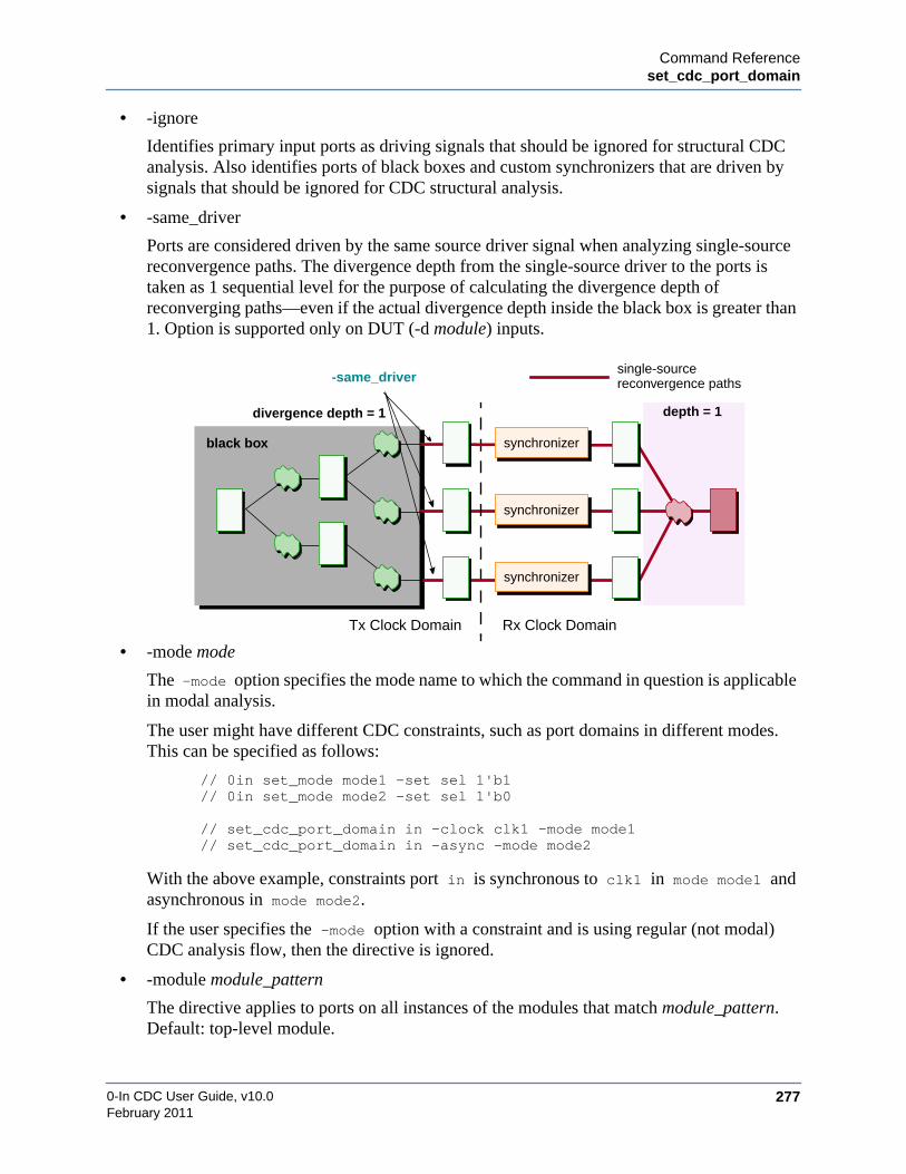
Command Referenceset_cdc_port_domain
0-In CDC User Guide, v10.0 277February 2011
• -ignore
Identifies primary input ports as driving signals that should be ignored for structural CDCanalysis. Also identifies ports of black boxes and custom synchronizers that are driven bysignals that should be ignored for CDC structural analysis.
• -same_driver
Ports are considered driven by the same source driver signal when analyzing single-sourcereconvergence paths. The divergence depth from the single-source driver to the ports istaken as 1 sequential level for the purpose of calculating the divergence depth ofreconverging paths—even if the actual divergence depth inside the black box is greater than1. Option is supported only on DUT (-d module) inputs.
• -mode mode
The -mode option specifies the mode name to which the command in question is applicablein modal analysis.
The user might have different CDC constraints, such as port domains in different modes.This can be specified as follows:
// 0in set_mode mode1 -set sel 1'b1// 0in set_mode mode2 -set sel 1'b0
// set_cdc_port_domain in -clock clk1 -mode mode1// set_cdc_port_domain in -async -mode mode2
With the above example, constraints port in is synchronous to clk1 in mode mode1 andasynchronous in mode mode2.
If the user specifies the -mode option with a constraint and is using regular (not modal)CDC analysis flow, then the directive is ignored.
• -module module_pattern
The directive applies to ports on all instances of the modules that match module_pattern.Default: top-level module.
depth = 1
Tx Clock Domain Rx Clock Domain
synchronizer
synchronizer
synchronizer
divergence depth = 1
single-sourcereconvergence paths
black box
-same_driver

0-In CDC User Guide, v10.0278
Command Referenceset_cdc_port_domain
February 2011
• -same_clock port_pattern…
This option is used only for hierarchical verification. The -same_clock option is specifiedfor an input port. This option is used to specify that the port should be in the same clockdomain as the other ports. If the two ports are not clocked on the same clock, then a warningis printed. This models cases when two ports of a block are connected to a DMUXsynchronizer. One of the ports goes to the select of the DMUX and the other goes to the databus. The same clock constraint ensures that the DMUX select and data are clocked on thesame clock.
• -combo_logic
This option is used only for hierarchical verification. Identifies a hierarchical block’sinput ports with combinational fanout logic and output ports with combinational fanin logic(for hierarchical CDC analysis). With this information, CDC analysis can detectcombinational logic before synchronizers:
• -combo_path primary_input_port…
This option is used only for hierarchical verification. This option is used to model acombination path from a list of primary inputs to a primary output. The option specified foran output port, indicates a combinational path from the input ports to the output. The optiontakes a list of string names that are the names of primary inputs which have a combinationalpath to that output. While computing the output’s port domain, the input’s port domain istaken into account. In case of conflicting input port domains, the output port domain isinferred as -async. The -combo_path option is also used in clock propagation when the inputis connected to a clock. The output is then treated as a clock and propagated forward.
clock_bclock_a
data_a data_bsynchronizer
combinationallogic
black box
-combo_logic
port_a
black box
combinationallogic
port_b
-combo_path port_a port_b

Command Referenceset_cdc_port_domain
0-In CDC User Guide, v10.0 279February 2011
• -nosync
This option is used only for hierarchical verification. The -nosync option is specified foran input port. This option is used to model a primary input port that is connected to flip-flops clocked on different clock domains. Such a port is declared as nosync because anycrossing to such a port is a missing synchronizer. In other words, specifies that the port issampled by a different clock and therefore, is a bad crossing.
Description
The set_cdc_port_domain global directives identify the clock domain characteristics of theports of the top-level module and internal black boxes. Without information fromset_cdc_port_domain directives, CDC only has the logic driven inside the DUT when itanalyzes clock domain crossings that originate outside the DUT logic. Theset_cdc_port_domain directives have two uses:
• Enable reporting of clock domain crossings originating outside the DUT.
CDC extrapolates what it can from the DUT logic, but since the information isincomplete, reporting all CDC paths can introduce too much “noise.” Reporting of therelated schemes is disabled by default. The set_cdc_port_domain directives provide thedetails needed to properly analyze crossings through primary ports, so CDC analysisreports schemes involving these ports.
• Pass hierarchical CDC information from an analyzed hierarchical level to be used in thecurrent level analysis.
This information is generated automatically by the CDC tool during hierarchical CDCanalysis of other hierarchical levels. The hierarchical_CDC_options (-same_clockport_pattern…, -combo_logic, -combo_path primary_input_port… and -nosync) arereserved for hierarchical CDC sessions and generate warnings if the hierarchical data forthe ports is missing.
black box-nosync
clk_a
clk_b
sampled bydifferent clock

0-In CDC User Guide, v10.0280
Command Referenceset_cdc_port_domain
February 2011
Examples
1. Each set_cdc_port_domain global directive with a -clock argument assigns allmatching ports to the same clock domain (that is, the directive does not assign tomultiple clock domains). For example,
module cdc_ctrl;// 0in set_cdc_port_domain a b c –clock U1.clk_A// 0in set_cdc_port_domain d –clock U2.clk_B
endmodule
Wildcards for set_cdc_port_domain directive-----------------------------------------------------------------
File t9_ctrl.v : Line 5-----------------------------------------------------------------*t1 matches
rst1aint1aout1bout1
Wildcards for set_cdc_port_domain directive with -module-----------------------------------------------------------------
File t9_ctrl.v : Line 6-----------------------------------------------------------------u*d in module dff3 matches
u0.d
File t9_ctrl.v : Line 7-----------------------------------------------------------------u*d in module dff5 matches
u0.d
File t9_ctrl.v : Line 8-----------------------------------------------------------------a*2 in module dut matches
aint2aout2
2. This example illustrates single-source reconvergence using the set_cdc_port_domain
global directive -same driver option. This example, uses the -same_driver optionof the set_cdc_port_domain global directive to report diverging points of primaryports having the same driver. With the single-source depth of 2, use the following globaldirectives:
// 0in set_cdc_port_domain p2 p3 in[1:4] -same_driver// 0in set_cdc_reconvergence -divergence_depth 2
This results in ports p2, p3 and in[1:4] being reported.
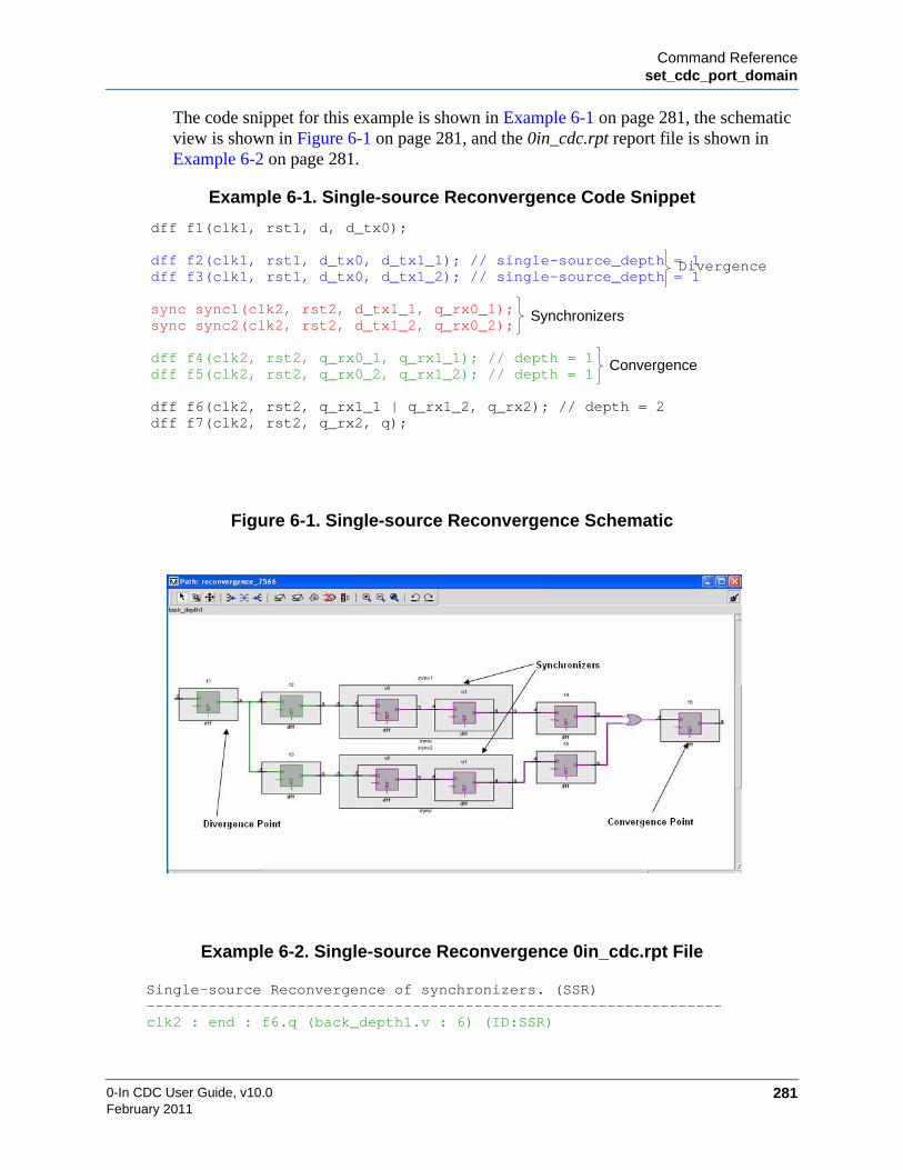
Command Referenceset_cdc_port_domain
0-In CDC User Guide, v10.0 281February 2011
The code snippet for this example is shown in Example 6-1 on page 281, the schematicview is shown in Figure 6-1 on page 281, and the 0in_cdc.rpt report file is shown inExample 6-2 on page 281.
Example 6-1. Single-source Reconvergence Code Snippet
Figure 6-1. Single-source Reconvergence Schematic
Example 6-2. Single-source Reconvergence 0in_cdc.rpt File
Single-source Reconvergence of synchronizers. (SSR)-----------------------------------------------------------------clk2 : end : f6.q (back_depth1.v : 6) (ID:SSR)
dff f1(clk1, rst1, d, d_tx0);
dff f2(clk1, rst1, d_tx0, d_tx1_1); // single-source_depth = 1dff f3(clk1, rst1, d_tx0, d_tx1_2); // single-source_depth = 1
sync sync1(clk2, rst2, d_tx1_1, q_rx0_1);sync sync2(clk2, rst2, d_tx1_2, q_rx0_2);
dff f4(clk2, rst2, q_rx0_1, q_rx1_1); // depth = 1dff f5(clk2, rst2, q_rx0_2, q_rx1_2); // depth = 1
dff f6(clk2, rst2, q_rx1_1 | q_rx1_2, q_rx2); // depth = 2dff f7(clk2, rst2, q_rx2, q);
Divergence
Synchronizers
Convergence

0-In CDC User Guide, v10.0282
Command Referenceset_cdc_port_domain
February 2011
clk2 : start : sync2.u1.q (back_depth1.v : 6) (SynchronizerID:two_dff_19004)
clk2 : start : sync1.u1.q (back_depth1.v : 6) (SynchronizerID:two_dff_18748)
clk1 : diverge : f1.q (back_depth1.v : 6) (ID:SSR_7566)
Command Referenceset_cdc_preference
0-In CDC User Guide, v10.0 283February 2011
set_cdc_preferenceSets preferences for CDC static analysis.
Syntax
set_cdc_preference [-multi_clock_convergence] [-unrestricted_reconvergence][-clock_in_data] [-infer_clock_off] [-allow_enable_in_sync][-max_cdc_crossings number] [-custom_fx] [-promote_reconvergence][-promote_async_reset] [-dmux_promote_sample] [-sample_data_stability][-mult_fanout_async] [-input_async] [-handshake_scheme] [-fifo_scheme][-delayed_pulse] [-detect_primary_output_clock] [-detect_pure_latch_clock][-formal_add_bus_stability] [-formal_add_recon_stability] [-filtered_report] [-vectorize_nl][-ignore_black_box] [-blackbox_empty_module] [-dmux_as_recon_start][-complex_scheme_as_synchronizer] [-multi_paths] [-clock_as_rx] [-report_bbox_recon][-report_resets] [-report_undriven_custom_sync] [-print_port_domain_template][-print_detailed_custom_sync] [-infer_modes_off]
• -multi_clock_convergence
Reports reconvergence with synchronizers in different Rx clock domains or coming fromdifferent Tx clock domains.
• -unrestricted_reconvergence
Reports reconvergence for unsynchronized paths (i.e., paths with missing synchronizers,combo logic, and so on). Default: reconvergent paths reported only if no other schemesapply.
• -clock_in_data
Reports all crossings, including clock signals that go to data inputs of registers. In somecases, runtime can increase substantially. Default: CDC crossings of signals used as bothclock and data are not reported.
• -infer_clock_off
Disables clock inference. Only user-specified clocks (i.e., specified by set_cdc_clock) areassumed to be clocks. This option lets you avoid grouping inferred clocks. Default: CDCclock analysis infers clocks.
• -allow_enable_in_sync
Recognizes 2-DFF synchronizers with enable signals in the DFFs. Default: 2-DFFsynchronizers with enables are not recognized as 2-DFF synchronizers.
• -max_cdc_crossings number
Limits the number of CDC crossings analyzed. Once this limit is reached, no more crossingsare analyzed. You can use this option to reduce session time when initially setting up adesign for CDC analysis. Default: no limit (number = 0).

0-In CDC User Guide, v10.0284
Command Referenceset_cdc_preference
February 2011
• -custom_fx
Allows tx signals in CDC-FX checkers to come from ports and custom synchronizers andallows rx signals to drive custom synchronizers. Injection occurs when tx and rx clocks arealigned and the checker fires when data changes in the metastability window. With thisoption more false violations can occur. Default: tx signals must come from registers and rxsignals must drive only registers.
• -promote_reconvergence
Promotes cdc_hamming1 checkers for reconvergence schemes. Default: checkers are notpromoted for reconvergence schemes.
• -promote_async_reset
Promotes cdc_sync checkers for async_reset and async_reset_no_sync schemes. Default:checkers are not promoted for async_reset and async_reset_no_sync schemes.
• -dmux_promote_sample
Promotes cdc_sample checkers for dmux schemes. Default: no protocol checkers arepromoted for dmux schemes.
• -sample_data_stability
Turns on the data_sample check (by specifying -tx_min) for all promotedcdc_hamming_one checkers. Default: cdc_hamming_one checkers are promoted with thedata_sample check turned off.
• -mult_fanout_async
Identifies input ports that fan out to multiple clock domains as asynchronous ports. Default:one clock domain is selected.
• -input_async
Identifies all DUT input ports as asynchronous ports. Default: all inputs are assumed to besynchronous with their fanout logic.
• -handshake_scheme
Identifies HANDSHAKE CDC schemes. Default: HANDSHAKE CDC schemes arereported as dmux or multi_bits schemes.
• -fifo_scheme
Identifies FIFO CDC schemes. Default: FIFO CDC schemes are reported as memory_syncor multi_bits schemes.
• -delayed_pulse
Recognizes pulse schemes that have a register to delay the output of the pulse synchronizer.
• -detect_primary_output_clock
Detects primary output clocks. An output port of the top module is inferred as a clock port ifthe fanin logic of the port has a signal either specified as a clock (with set_cdc_clock) or isused to clock a register/latch. Default: clocks are not inferred for top-level output ports.
Command Referenceset_cdc_preference
0-In CDC User Guide, v10.0 285February 2011
• -detect_pure_latch_clock
Assumes latch enables are clocks. Default: only latch enable signals that clock anotherregister or that are specified with set_cdc_clock are recognized as clock signals.
• -formal_add_bus_stability
Adds checks for signal stability to the synchronization schemes’ gray-coding protocolsverified by formal CDC.
• -formal_add_recon_stability
Adds checks for signal stability to the reconvergence schemes’ gray-coding protocolsverified by formal CDC.
• -filtered_report
Identifies filtered CDC schemes in the CDC report and in the 0in_cdc static CDC analysisresults (GUI). With this preference, schemes identified using the set_cdc_report globaldirective as filtered (-severity off) and schemes with stable transmit domain signals(set_cdc_signal -stable) are reported. Caution: Can result in increased runtime and memoryusage if many set_cdc_report -severity off with wildcards are specified. Default: Filteredschemes are not reported.
• -vectorize_nl
Reports as a single-bus synchronizer (for example, BUS_TWO_DFF) each CDC schemewhere the signals start from the same bus, all the signals are synchronized by the samesynchronization scheme and all signals are merged back into a single bus aftersynchronization. Default: Bus bits that are separately synchronized are reported as single-bitCDC schemes (for example, TWO_DFF).
• -ignore_black_box
Do not report CDC blackbox crossings to the ports of any blackbox design units that do nothave port domain definitions. Default: report blackbox crossing schemes to ports withoutport domain definitions for inferred blackbox design units. Crossings to user-specifiedblackbox design units are never reported as blackbox schemes.
• -blackbox_empty_module
Turns all empty (i.e., stub) modules/entities into inferred black boxes. An emptymodule/entity is one for which a module or entity/architecture definition is present, but thecontent is empty. That is, only the I/O ports (with directions) are declared. This option doesnot apply to unresolved modules/entities. Crossings to or from inferred black boxes arereported to guard against possible real clock domain crossings. To eliminate “falsepositives” you should indicate the port domains of inferred black boxes usingset_cdc_port_domain directives. Default: empty modules are analyzed as regular modules.
• -dmux_as_recon_start
Recognizes dmux, simple_dmux and multi_sync_mux_select schemes as starting points forreconvergence schemes.
0-In CDC User Guide, v10.0286
Command Referenceset_cdc_preference
February 2011
• -complex_scheme_as_synchronizer
Recognizes dmux schemes that have complex synchronizers as the MUX-selectsynchronizer. Default: to report a dmux scheme, its MUX-select synchronizer must be atwo_dff synchronizer.
• -multi_paths
Reports all the paths for each clock domain crossing (i.e., Tx/Rx pair). This option canreduce performance significantly. Default: Only one path per crossing is reported in theCDC report.
• -report_bbox_recon
Reports reconvergence schemes that reconverge at black boxed instances. Default: theseschemes are not reported.
• -clock_as_rx
Reports clock domain crossings to Rx nodes that have clock signals in their fanin cones (andare not registers, latches, primary outputs, or inputs to custom synchronizers or blackboxes)—unless Tx is part of the clock tree. Default: these crossings are not reported.
• -report_resets
Reports reset tree data in the design report. Default: reset trees are not reported.
• -report_undriven_custom_sync
Reports as instances of the custom_sync scheme custom synchronizer crossings originatingfrom internal or undriven wires. Default: only reports custom synchronizers that are drivenby ports.
• -print_port_domain_template
Creates a 0in_cdc_port_domain_template.v file with the set_cdc_port_domain directivesfor the primary ports. Use this template as a starting point for setting up theset_cdc_port_domain constraints. CDC analysis cannot identify the clock domains of theports as they depend on the DUT external environment. You should review the constraintsand adjust as necessary. You can ignore set_cdc_clock directives in the template if you havespecified the set_cdc_clock directives in a control file.
• -print_detailed_custom_sync
Reports custom synchronizers on signals that are not reported as CDC crossings (see“Custom Synchronization Modules” on page 458). Default: these signals are not reported.To report a custom synchronizer in a CDC crossing, add the -tx/-rx arguments to theset_cdc_port_domain specification.
• -infer_modes_off
Turns off inferring of modes during cdc -report_modes sessions. Used in specialcircumstances to reduce cdc run time: if you know the user-defined modes are complete,you do not need to infer other modes. For example, if you run a default -report_modessession and define the inferred modes with set_mode, you can re-run cdc -report_modeswith mode inference disabled. Default: -report_modes performs mode inference.

Command Referenceset_cdc_preference
0-In CDC User Guide, v10.0 287February 2011
Description
This global directive defines preferences for CDC. The status of the CDC preferences is printedin the 0in_detail.log file (see Figure 6-2).
Figure 6-2. Global CDC Preferences (0in_detail.log)
Examples
// 0in set_cdc_preference -allow_enable_in_sync
// 0in set_cdc_preference -clock_in_data
// 0in set_cdc_preference -max_cdc_crossings 200
// 0in set_cdc_preference -filtered_report
Global CDC Preferences---------------------------------------------------------------------
Option Value
---------------------------------------------------------------------
multi_clock_convergenceclock_in_dataallow_enable_in_syncmax_cdc_crossingscustom_fxpromote_reconvergencemult_fanout_asyncdmux_promote_sampleignore_black_boxinput_asynchandshake_schemefifo_schemedelayed_pulsereport_resetsdetect_primary_output_clockformal_add_bus_stabilityformal_add_recon_stabilityfiltered_report
FALSEFALSEFALSE0FALSETRUETRUEFALSEFALSEFALSEFALSETRUETRUETRUEFALSEFALSEFALSEFALSE
filtered_reportvectorize_nlunrestricted_reconvergencemulti_pathsreport_undriven_custom_syncprint_port_domain_templatedmux_as_recon_startprint_detailed_custom_syncreport_bbox_reconreport_bbox_reconblackbox_empty_modulesample_data_stabilityinfer_clock_offdetect_pure_latch_clockpromote_async_resetcomplex_scheme_as_synchronizerinfer_modes_off
FALSEFALSEFALSEFALSETRUEFALSEFALSEFALSEFALSEFALSEFALSETRUETRUETRUEFALSEFALSEFALSE
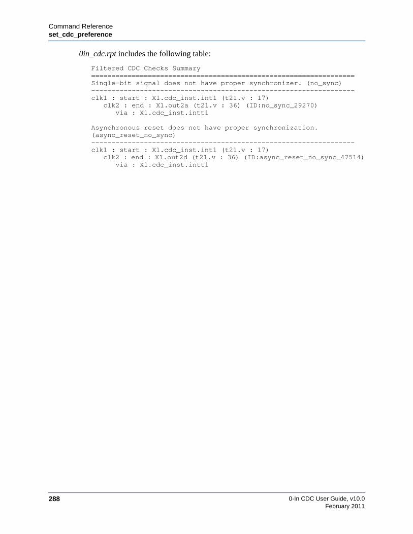
0-In CDC User Guide, v10.0288
Command Referenceset_cdc_preference
February 2011
0in_cdc.rpt includes the following table:
Filtered CDC Checks Summary=================================================================Single-bit signal does not have proper synchronizer. (no_sync)-----------------------------------------------------------------clk1 : start : X1.cdc_inst.int1 (t21.v : 17)
clk2 : end : X1.out2a (t21.v : 36) (ID:no_sync_29270)via : X1.cdc_inst.intt1
Asynchronous reset does not have proper synchronization.(async_reset_no_sync)-----------------------------------------------------------------clk1 : start : X1.cdc_inst.int1 (t21.v : 17)
clk2 : end : X1.out2d (t21.v : 36) (ID:async_reset_no_sync_47514)via : X1.cdc_inst.intt1

Command Referenceset_cdc_protocol
0-In CDC User Guide, v10.0 289February 2011
set_cdc_protocolIdentifies a CDC protocol checker type to promote for one or more custom synchronizermodules.
Syntax
set_cdc_protocolchecker_type -module custom_synch_pattern [-rx_clock clock] [-tx_var signal]
• checker_type
Type of checker to promote. Currently, only values of cdc_sync and cdc_hamming1 aresupported.
• -module custom_synch_pattern
Custom synchronizer modules.
• -rx_clock clock
Rx clock signal in the synchronizer. Default: if the synchronizer has only one clock port,that clock is inferred as the Rx clock. Otherwise, a warning is issued and the directive isskipped.
• -tx_var signal
Transmit domain CDC input signal in the synchronizer. Default: if the synchronizer hasonly one data input port, that signal is inferred as tx_var. Otherwise, a warning is issued andthe directive is skipped.
Description
Used with the set_cdc_synchronizer directive to identify custom synchronizers for CDCanalysis. Static CDC analysis assumes each module specified by a set_cdc_synchronizerdirective is a custom synchronizer. The set_cdc_protocol directive indicates a type of checker topromote to check the CDC transfer protocol for schemes that are synchronized by one of thematching synchronizers. The directive needs the module name pattern of the synchronizers andthe checker type for the promoted protocol checkers. Currently, only the cdc_sync andcdc_hamming1 checker types are supported.
A basic custom synchronizer has an Rx clock input, a Tx domain input and an Rx domainoutput. Currently, this is the only type of custom synchronizer supported by set_cdc_protocol.If two set_cdc_protocol directives reference the same port, a directive-273 warning is issuedand the second directive is ignored.

0-In CDC User Guide, v10.0290
Command Referenceset_cdc_protocol
February 2011
Example
// 0in set_cdc_synchronizer cust -module cust_sync1// 0in set_cdc_port_domain D -async -module cust_sync1// 0in set_cdc_protocol cdc_sync -module cust_sync1
Promotes the following checker directive, where tx_var is the signal connected to the Dport of the cust_sync1 instance, tx_clock is the inferred clock in cust_sync1 andclock_ratio is the ratio of the inferred Rx/Tx clocks.
/* 0in cdc_sync-tx_var tx_var -tx_clock tx_clock -tx_min clock_ratio */

Command Referenceset_cdc_reconvergence
0-In CDC User Guide, v10.0 291February 2011
set_cdc_reconvergenceSpecifies reconvergence control parameters.
Syntax
set_cdc_reconvergence [-check off] [-depth depth] [-divergence_depth depth][-tx_clock clock] [-rx_clock clock] [-bit_recon]
• -check off
The -check option is used to turn off reconvergence checking totally. The default is On.
• -depth depth
Maximum sequential reconvergence depth for reporting reconvergence and single-sourcereconvergence CDC schemes.
The sequential reconvergence depth is the number of sequential levels from the storageelement after the synchronizer to the reconvergence point. In cases where the reconvergentpaths have different numbers of levels, the sequential reconvergence depth is the largestnumber of sequential levels. For example, suppose paths A and B are reconvergent with 5and 8 sequential levels to the reconvergence point respectively. Then this scheme instance isnot reported as a reconvergence violation if set_cdc_reconvergence sets -depth 5, but isreported if set_cdc_reconvergence sets -depth 8. Default: 0.
• -divergence_depth depth
Enables reporting of single-source reconvergence and sets the divergence depth. Default:instances of SSR schemes are reported only as reconvergence schemes.
–depth 3
Tx Clock Domain Rx Clock Domain
synchronizer
synchronizer
synchronizer
reconvergence combinationalpaths logic
3 sequential
3 sequential
2 sequential
levels
levels
levels

0-In CDC User Guide, v10.0292
Command Referenceset_cdc_reconvergence
February 2011
• -tx_clock clock
Restricts the directive to paths originating in the Tx clock domain.
• -rx_clock clock
Restricts the directive to paths terminating in the Rx clock domain.
• –bit_recon
Report as instances of the reconvergence scheme, those paths where the individual bits ofthe output of a bus 2DFF synchronizer are re-combined.
Description
Use this global directive to specify reconvergence control parameters.
–depth 2
Tx Clock Domain Rx Clock Domain
synchronizer
synchronizer
synchronizer
–divergence_depth 2
single-sourcereconvergence
combinational
pathslogic
bus 2DFF
re-converging bits
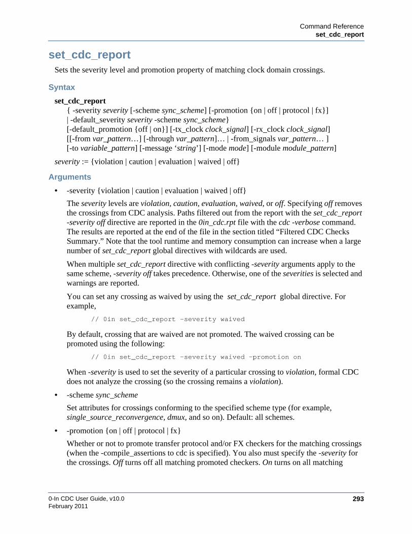
Command Referenceset_cdc_report
0-In CDC User Guide, v10.0 293February 2011
set_cdc_reportSets the severity level and promotion property of matching clock domain crossings.
Syntax
set_cdc_report{ -severity severity [-scheme sync_scheme] [-promotion {on | off | protocol | fx}]| -default_severity severity -scheme sync_scheme}[-default_promotion {off | on}] [-tx_clock clock_signal] [-rx_clock clock_signal][[-from var_pattern…] [-through var_pattern]… | -from_signals var_pattern… ][-to variable_pattern] [-message ‘string’] [-mode mode] [-module module_pattern]
severity := {violation | caution | evaluation | waived | off}
Arguments
• -severity {violation | caution | evaluation | waived | off}
The severity levels are violation, caution, evaluation, waived, or off. Specifying off removesthe crossings from CDC analysis. Paths filtered out from the report with the set_cdc_report-severity off directive are reported in the 0in_cdc.rpt file with the cdc -verbose command.The results are reported at the end of the file in the section titled “Filtered CDC ChecksSummary.” Note that the tool runtime and memory consumption can increase when a largenumber of set_cdc_report global directives with wildcards are used.
When multiple set_cdc_report directive with conflicting -severity arguments apply to thesame scheme, -severity off takes precedence. Otherwise, one of the severities is selected andwarnings are reported.
You can set any crossing as waived by using the set_cdc_report global directive. Forexample,
// 0in set_cdc_report -severity waived
By default, crossing that are waived are not promoted. The waived crossing can bepromoted using the following:
// 0in set_cdc_report -severity waived -promotion on
When -severity is used to set the severity of a particular crossing to violation, formal CDCdoes not analyze the crossing (so the crossing remains a violation).
• -scheme sync_scheme
Set attributes for crossings conforming to the specified scheme type (for example,single_source_reconvergence, dmux, and so on). Default: all schemes.
• -promotion {on | off | protocol | fx}
Whether or not to promote transfer protocol and/or FX checkers for the matching crossings(when the -compile_assertions to cdc is specified). You also must specify the -severity forthe crossings. Off turns off all matching promoted checkers. On turns on all matching

0-In CDC User Guide, v10.0294
Command Referenceset_cdc_report
February 2011
promoted checks. FX checkers are generated only if the -fx option to cdc is specified.Protocol turns on just the protocol checkers; fx turns on just the FX checkers.
• -default_severity {violation | caution | evaluation | waived | off}
Sets the default severity for the specified scheme type. Directive is ignored if any argumentsother than -scheme and -module are specified.
• -default_promotion {off | on}
Whether or not to promote a CDC protocol assertion if no other -promotion options apply.Although by default CDC protocol assertion promotion is on, the -default_promotion on isuseful when severity or default severity is off (which usually turns off CDC protocolassertion promotion). For example, the following directive turns severity off forbus_shift_reg schemes, but retains CDC protocol assertion promotion:
/* 0in set_cdc_report -scheme bus_shift_reg -severity off-default_promotion on */
• -tx_clock clock_signal
Crossings from transmission logic clocked by a particular clock.
• -rx_clock clock_signal
Crossings to receive logic clocked by a particular clock.
• -from variable_pattern, -to variable_pattern, -through variable_pattern
One or more paths that include CDC crossings. You can specify any combination of-from, -to, and -through arguments (but multiple -from variables only are allowed for thereconvergence and single_source_reconvergence schemes).
The -through variable_pattern argument specifies a wire in the paths. These wires are thewaypoints shown as VIA points in the CDC report. You can include wildcards and slices invariables and wire names. To match the specification, a path must pass through wiresspecified by every -through argument. The directive is ignored if you specify -through with-scheme reconvergence or -scheme single_source_reconvergence and a directive-214warning is issued: Unmatched CDC crossing specified.
If a CDC crossing originates from (-from) or ends at (-to) a stable variable (see“set_cdc_signal” on page 299), then the crossing is removed from CDC analysis. Eventhough the -to variable_pattern does not support multiple signal names, a wildcard patterncan be specified that has multiple matches. For example, the following directive turns offmultiple crossings:
//0in set_cdc_report -to a.gen*.c -severity off
Schemes other than the reconvergence scheme do not allow specification of more than onesignal in the -from option (including wildcard matches). A directive that violates this rule isignored, in which case the CDC compiler issues a warning message.
In the special case of reconvergence to black boxes (i.e., set_cdc_preference-report_bbox_recon) the -to variable_pattern can be the instance name pattern of one or

Command Referenceset_cdc_report
0-In CDC User Guide, v10.0 295February 2011
more black-boxed modules. To be considered a reconvergent path, the two converging pathsneed only end at any port of the same black boxed instance.
• -from_signals variable_pattern…
This option is used only for reconvergence analysis. Specifies variables that identifyregisters or wires that contain data in one clock domain that are separately synchronized andthen recombined in another clock domain. The difference between -from and -from_signalsis that -from takes the OR of the signals and -from_signals takes the AND of the signals.
You must specify -scheme reconvergence with this option, otherwise, the directive isignored and the CDC compiler issues the following warning message:
Warning: Reconvergence scheme must be used when the -from_signalsoption is specified.
Directive ‘set_cdc_report’.: Directive will be ignored.[hdl-86]
If both -from and -from_signals options are specified, the directive is ignored and the CDCcompiler issues the following warning message:
Warning: Options from and from_signals specified.Directive ‘set_cdc_report’.
: Directive will be ignored.[hdl-104]
If the variable_patterns have no wildcards, the list of signals must be complete—inparticular, the list must include two or more signals—the directive only applies toreconvergence instances where all of the specified source signals reconverge.
If the variable_patterns have wildcards, the directive only applies to reconvergenceinstances where every variable_pattern has a matching start point and the matched startpoints are complete. Fore example, consider the following argument:
–from_signals A* B C
The directive matches reconverging paths that have the following (complete) sets of startpoints: (A1 B C) and (A1 A2 B C). The directive does not match reconverging paths thathave the following (complete) sets of start points: (B C) and (A1 B C E).
• -message ‘string’
Message string to add to the path reports of matching CDC schemes. Default: no messageadded.
• -mode mode
The -mode option specifies the mode name to which the command in question is applicablein modal analysis. If you specify the -mode option with a constraint and is using regular(not modal) CDC analysis flow, then the directive is ignored.
• -module module_pattern
The global directive applies to matching CDC crossings in all instances of the modulespecified by module_pattern. Wildcards are allowed, in which case the directive applies to

0-In CDC User Guide, v10.0296
Command Referenceset_cdc_report
February 2011
all instances of the matching modules. If the -module option is omitted, then the directiveapplies the -d module.
Example 1:
//0in set_cdc_report -module A -severity caution
Only crossings completely within the same instance of A are set to caution.Crossings across instances of A are not affected.
Example 2:
//0in set_cdc_report -module A -from B -severity caution
Crossings in which the from signal is X.B are set to caution, where X is anyinstance of module A.
Description
The set_cdc_report global directive sets the severity level and promotion property of matchingclock domain crossings. Use this directive to override the default severity and promotion ofclock domain crossing checks.
Specify one of the following:
• -severity severity — with an optional -scheme or -promotion.
• -default_severity severity -scheme sync_scheme
If you do not specify other arguments, then the directive applies to all CDC crossings. If you donot specify other arguments except -module module, then the directive applies only to crossingsentirely within module. Otherwise, you can specify a combination of arguments to identify oneor more CDC crossings. The specified crossings are all of those that match all of the criteria. If-module module is specified, these crossings need not lie completely inside module.
Note that an increase in runtime and memory usage can occur when a large number ofset_cdc_report global directives with wildcards are used with the -verbose option of cdc. Also,-severity off turns off promotion—so, -severity off -promotion on generates a warning messageand the directive is ignored.
Example 1: set_cdc_report
module cdc_ctrl;/* 0in set_cdc_report -scheme blackbox
-from out2a -to bb1.* -severity off */// 0in set_cdc_report -scheme two_dff_phase -severity evaluation
endmodule

Command Referenceset_cdc_report
0-In CDC User Guide, v10.0 297February 2011
Example 2: -verbose Option
Following are -verbose examples:
-verbose and wildcard expansion
//0in set_cdc_report -from A*B -severity off
If A*B is an invalid signal and does not exist in the design
Without -verbose
Warning message — directive-214
With -verbose
Warning message — hdl-77
-verbose and reconvergence
/*0in set_cdc_report -from_signals A* B* C* -scheme reconvergence-severity off */
Case 1
For reconvergences from (A, B) to (D)(G, E, F) to (H)(AL, BL, CL, DL) to (M)
With -verbose
The reconvergences ending at D and M have at least one matching start point so thefollowing warning messages should appear:
Warning message — directive-235 for recon ending at D for C*directive-236 for recon ending at M for DL
Without -verbose
Warning message — directive-214
Case 2
For reconvergences from (G, E, F) to (H)(X, Y, Z) to (M).
With and without -verbose
Warning message — directive-214, since not even one start point matched in any ofthe reconvergences.

0-In CDC User Guide, v10.0298
Command Referenceset_cdc_report
February 2011
Case 3
If there are reconvergences from (A, B) to (D)(G, E, F) to (H)(AL, BL, CL) to (M)
With and without -verbose
No warning message because (Al, BL, CL) matched exactly.
Example 3: Set All DMUX Crossings to Evaluation
This example illustrates using the set_cdc_report global directive to set all DMUXcrossings to evaluation, except for those that start from A and end at B.
// 0in set_cdc_report -scheme demux -severity evaluation// 0in set_cdc_report -from A -to B -severity waived
Warnings are produced when there are conflicts.

Command Referenceset_cdc_signal
0-In CDC User Guide, v10.0 299February 2011
set_cdc_signalReclassifies the CDC signal type of specified CDC signals or adds properties to specified CDCsignals.
Syntax
set_cdc_signalvariable_pattern… [-split] [-stable] [-gray_coded] [-module module_pattern] [-mode mode][-merge]
• variable_pattern…
One or more CDC signals. Names can include wildcards and can be bit slices. Theclassification or CDC property assigned by the directive is applied to all matching variables.
• -split
Treats bits of the specified multiple-bit registers/latches as individual control signals forCDC analysis. By default, synchronization of a CDC data bus must be performed on thewhole bus. If not, then the bus is marked with a BUS SYNC warning. But, if a register hasonly one bit derived from a CDC signal, then synchronization of that bit should be allowed.For example, a status bit might be extracted from a state variable or a single multiple-bitregister (for example, a status register) might store amalgamated control signals. Splitting aCDC data bus for CDC analysis eliminates the BUS SYNC warning.
Treating bits individually is independent of the synchronization type: the bits can besynchronized with control synchronization (for example, 2DFF) or data synchronization(for example, DMUX). You might want to treat bits in a bus individually for any of thefollowing reasons:
• Only some bits of the bus cross a clock domain boundary.
• Different bits in the bus go to different clock domains.
• The bus is a collection of individual signals (such as status signals) that you want toconsider as individual bits.
Various bits of a split bus can be used together in the destination domain (for example, in areceiving state machine decoding). To check for reconvergence problems, CDC analysisidentifies these crossings as potential RECONVERGENCE warnings.
• -gray_coded
Identifies the specified variables as properly gray-coded data buses for CDC analysis.
2DFF and four latch synchronizations can be valid for a gray-coded data bus. So by default,checks for CDC data buses that have either of these types of synchronizers are promoted asa cdc_hamming_distance_one checkers to verify gray-coding and synchronization.Identifying a particular variable as gray-coded indicates the data bus is properly gray-coded(that is, with gray coder/decoder logic), so gray-code checking is unnecessary. In this case,the crossing check is promoted as a cdc_sync checker.

0-In CDC User Guide, v10.0300
Command Referenceset_cdc_signal
February 2011
• -stable
Identifies the specified variables as stable for CDC analysis. CDC analysis considers astable variable (and its propagated values) as properly synchronized.
The -stable option has no effect if signal is not an Rx or Tx of a CDC crossing, or if signalcannot be propagated to an Rx of a CDC crossing, or if signal drives an input ofcombinational logic whose output is not stable. To see the signals marked as stable that haveno effect on CDC analysis, specify the set_cdc_preference -filtered_report directive andreview the “Filtered CDC Checks Summary” section in 0in_cdc.rpt.
• -module module_pattern
The global directive applies to matching CDC signals in all instances of modules that matchmodule_pattern. If -module is omitted, the global directive applies to the -d module.
• -mode mode
The -mode option specifies the mode name to which the command in question is applicablein modal analysis. If you specify the -mode option with a constraint and is using regular(not modal) CDC analysis flow, then the directive is ignored.
• -merge
Merge the signals into a single signal for CDC analysis.
Description
The set_cdc_signal global directive reclassifies the CDC signal type of specified CDCsignals or adds properties to specified CDC signals. Use this directive to override the inferredclassifications of CDC signals and to identify synchronization properties of particular CDCsignals.
Specify the following:
• signals
• -split, -gray_coded, or -stable
Note that all CDC crossings filtered by the // 0in set_cdc_signal -stable global directive arereported at the end of the 0in_cdc.rpt file when the cdc -verbose command option is used.
Examples
Example 1
module cdc_ctrl;// 0in set_cdc_signal tx_status –control –module mtr// 0in set_cdc_signal write_addr –gray_coded –module pci_if
endmodule
The list of wildcard expanded signals are reported in the 0in_detail.log file. Following is asample control file showing the use of wildcards with the set_cdc_signal global directive:
module check;// 0in set_cdc_clock clk1

Command Referenceset_cdc_signal
0-In CDC User Guide, v10.0 301February 2011
// 0in set_cdc_clock clk2 -group g2// 0in set_cdc_signal out[1:4] -module dff20 -stable// 0in set_cdc_signal * -module dff40 -split// 0in set_cdc_signal q -module *10 -gray_coded
endmodule
Following is the information regarding the wildcard expanded signals that are reported in the0in_detail.log file for the above example:
Wildcards for set_cdc_signal directive with -module-----------------------------------------------------------------File t28_ctrl.v : Line 5-----------------------------------------------------------------* in module dff40 matches
clkrstenadq
File t28_ctrl.v : Line 6-----------------------------------------------------------------q in module dff10 matches
q
Example 2
Marking sig_a as stable has no effect on CDC analysis because the sig_b input to the combologic block might make sig_c unstable. Therefore, a combo_logic violation is reported.Specifying set_cdc_preference -filtered_report causes CDC analysis to report signals marked asstable that do not affect CDC analysis (see the 0in_cdc.rpt).
-stabletx_clk
rx_clkmight notbe stable
combologic
sig_a
sig_b sig_c
set_cdc_signal sig_a -stable has no effect
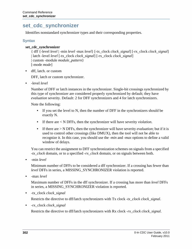
0-In CDC User Guide, v10.0302
Command Referenceset_cdc_synchronizer
February 2011
set_cdc_synchronizerIdentifies nonstandard synchronizer types and their corresponding properties.
Syntax
set_cdc_synchronizer{ dff {-level level | -min level -max level} [-tx_clock clock_signal] [-rx_clock clock_signal]| latch -level level [-tx_clock clock_signal] [-rx_clock clock_signal]| custom -module module_pattern}[-mode mode]
• dff, latch. or custom
DFF, latch or custom synchronizer.
• -level level
Number of DFF or latch instances in the synchronizer. Single-bit crossings synchronized bythis type of synchronizer are considered properly synchronized by default; they haveevaluation severity. Default: 2 for DFF synchronizers and 4 for latch synchronizers.
Note the following:
• If you set the level to N, then the number of DFF in the synchronizers should beexactly N.
• If there are < N DFFs, then the synchronizer will have severity violation.
• If there are > N DFFs, then the synchronizer will have severity evaluation; but if it isused to control other crossings (like DMUX), then the tool will not be able torecognize it. In this case, you should use the -min and -max options to define a validwindow of delays.
You can restrict the assignment to DFF synchronization schemes on signals from a specified-tx_clock domain, or to a specified -rx_clock domain, or on signals between both.
• -min level
Minimum number of DFFs to be considered a dff synchronizer. If a crossing has fewer thanlevel DFFs in series, a MISSING_SYNCHRONIZER violation is reported.
• -max level
Maximum number of DFFs in the dff synchronizer. If a crossing has more than level DFFsin series, a MISSING_SYNCHRONIZER violation is reported.
• -tx_clock clock_signal
Restricts the directive to dff/latch synchronizers with Tx clock -tx_clock clock_signal.
• -rx_clock clock_signal
Restricts the directive to dff/latch synchronizers with Rx clock -rx_clock clock_signal.
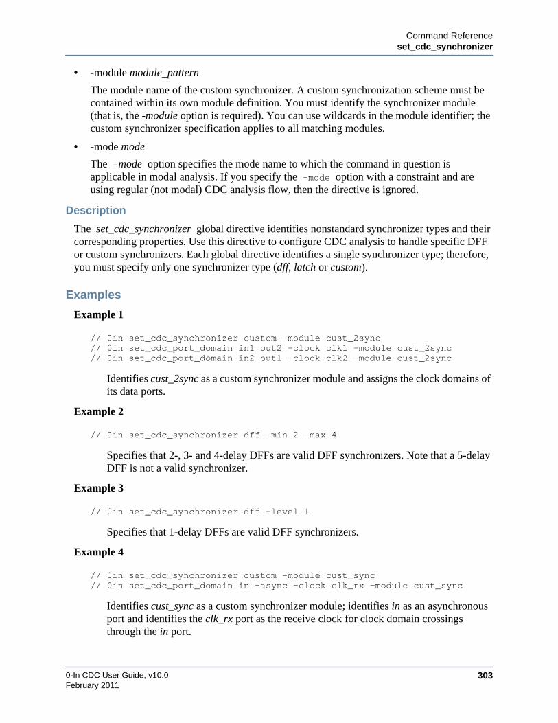
Command Referenceset_cdc_synchronizer
0-In CDC User Guide, v10.0 303February 2011
• -module module_pattern
The module name of the custom synchronizer. A custom synchronization scheme must becontained within its own module definition. You must identify the synchronizer module(that is, the -module option is required). You can use wildcards in the module identifier; thecustom synchronizer specification applies to all matching modules.
• -mode mode
The -mode option specifies the mode name to which the command in question isapplicable in modal analysis. If you specify the -mode option with a constraint and areusing regular (not modal) CDC analysis flow, then the directive is ignored.
Description
The set_cdc_synchronizer global directive identifies nonstandard synchronizer types and theircorresponding properties. Use this directive to configure CDC analysis to handle specific DFFor custom synchronizers. Each global directive identifies a single synchronizer type; therefore,you must specify only one synchronizer type (dff, latch or custom).
Examples
Example 1
// 0in set_cdc_synchronizer custom -module cust_2sync// 0in set_cdc_port_domain in1 out2 -clock clk1 -module cust_2sync// 0in set_cdc_port_domain in2 out1 -clock clk2 -module cust_2sync
Identifies cust_2sync as a custom synchronizer module and assigns the clock domains ofits data ports.
Example 2
// 0in set_cdc_synchronizer dff -min 2 -max 4
Specifies that 2-, 3- and 4-delay DFFs are valid DFF synchronizers. Note that a 5-delayDFF is not a valid synchronizer.
Example 3
// 0in set_cdc_synchronizer dff -level 1
Specifies that 1-delay DFFs are valid DFF synchronizers.
Example 4
// 0in set_cdc_synchronizer custom -module cust_sync// 0in set_cdc_port_domain in -async -clock clk_rx -module cust_sync
Identifies cust_sync as a custom synchronizer module; identifies in as an asynchronousport and identifies the clk_rx port as the receive clock for clock domain crossingsthrough the in port.

0-In CDC User Guide, v10.0304
Command Referenceset_cdc_synchronizer
February 2011
Example 5 (Internal-crossing Custom Synchronizer)
// 0in set_cdc_synchronizer custom –module INT_SYNC// 0in set_cdc_port_domain sig_tx –tx_clock clk_tx -module INT_SYNC// 0in set_cdc_port_domain sig_rx –rx_clock clk_rx -module INT_SYNC// 0in set_cdc_protocol cdc_sync -module INT_SYNC// 0in set_cdc_protocol cdc_hamming1 -module INT_SYNC
The INT_SYNC module is a custom synchronizer module where the transmitting registeris internal to the module. In particular, the clock domain crossing for the synchronizeroccurs within the custom synchronizer module itself. The set_cdc_synchronizerdirective specifies INT_SYNC as a custom synchronizer module. The twoset_cdc_port_domain directives declare the INT_SYNC to be an internal-crossingsynchronizer (compare with Example 1). The two set_cdc_protocol directives promotepulse-width and gray-code checkers for the driver of sig_tx.
An internal-crossing custom synchronizer module is identified when all the followingrequirements are met:
• A set_cdc_synchronizer custom directive with multiple clock ports is specified forthe module.
• No ports of the module are defined as asynchronous (set_cdc_port_domain -async).
• At least one transmit clock and one receive clock are identified using theset_cdc_port_domain options -tx_clock and -rx_clock.
clk_rx
Tx Clock Domain
sig_tx sig_rxDFFDFF
Rx Clock Domain
clk_tx
Internal-crossingCustom Synchronizer
INT_SYNC

Command Referenceset_constant
0-In CDC User Guide, v10.0 305February 2011
set_constantAssumes a variable is kept at a specified constant value for CDC analysis.
Syntax
set_constant variable_pattern… constant [-module module_pattern]
• variable_pattern…
Hierarchical name pattern for the variables, specified relative to the DUT. Pattern matchescan be bit slices.
• constant
Constant Verilog or VHDL value for variable. If constant has fewer bits than variable, thenconstant is zero-extended. If constant has more bits than variable, then the high-order bitsof constant are truncated. All nets connected to variable are forced to the constant value.
• -module module_pattern
Module or modules containing variable.
Description
CDC analysis keeps variable set to constant. This directive can be used on internal variables.The set_constant directive simplifies the CDC model by discarding part of the DUT circuitryduring cdc compilation. For example, this capability is useful for disabling test logic to reduceDUT size.
Example
// 0in set_constant U0.rst 1'b1
CDC analysis assumes the port U0.rst is held at 1'b1.
// 0in set_constant U0.in[1:4] 4'b1010
CDC analysis assumes the port slice U0.in[1:4] is held at 4'b1010.
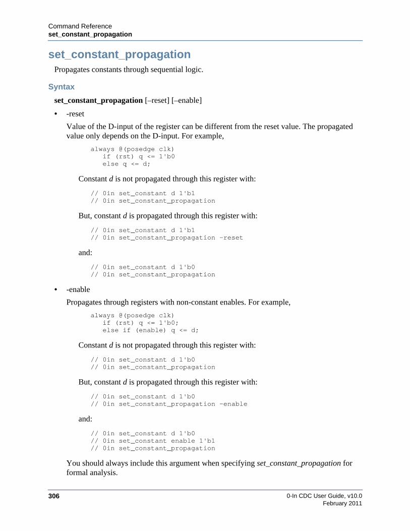
0-In CDC User Guide, v10.0306
Command Referenceset_constant_propagation
February 2011
set_constant_propagationPropagates constants through sequential logic.
Syntax
set_constant_propagation [–reset] [–enable]
• -reset
Value of the D-input of the register can be different from the reset value. The propagatedvalue only depends on the D-input. For example,
always @(posedge clk)if (rst) q <= 1'b0else q <= d;
Constant d is not propagated through this register with:
// 0in set_constant d 1'b1// 0in set_constant_propagation
But, constant d is propagated through this register with:
// 0in set_constant d 1'b1// 0in set_constant_propagation -reset
and:
// 0in set_constant d 1'b0// 0in set_constant_propagation
• -enable
Propagates through registers with non-constant enables. For example,
always @(posedge clk)if (rst) q <= 1'b0;else if (enable) q <= d;
Constant d is not propagated through this register with:
// 0in set_constant d 1'b0// 0in set_constant_propagation
But, constant d is propagated through this register with:
// 0in set_constant d 1'b0// 0in set_constant_propagation -enable
and:
// 0in set_constant d 1'b0// 0in set_constant enable 1'b1// 0in set_constant_propagation
You should always include this argument when specifying set_constant_propagation forformal analysis.
Command Referenceset_constant_propagation
0-In CDC User Guide, v10.0 307February 2011
Description
Simplifies CDC and formal models by propagating constant values set by the RTL source codeor by set_constant through sequential logic, including latches.

0-In CDC User Guide, v10.0308
Command Referenceset_memory
February 2011
set_memorySets the memory model type for specified multidimensional arrays.
Syntax
set_memory {{-exact | -abstract} [mem_pattern]…}… [-module module_pattern…]
• mem_pattern
Name pattern for one or more multidimensional arrays. Pattern can be hierarchical, cancontain wildcards and can be repeated. Default: *
• -exact | -abstract
How the arrays are modeled: -exact models the arrays as register logic; -abstract modelsthem as abstract memories. The default model for each multidimensional array isdetermined by heuristic analysis.
• -module module_pattern…
Module patterns for modules containing multidimensional arrays that matchmem_pattern…. Default: * (all modules).
Description
Selects the type of model to use (exact or abstract) for the specified multidimensional arrays.Used to override memory modeling assignments made by the csl and cdc compilationheuristics. The following example sets ram32x512 in module sram to be modeled as an abstractmemory and ram4x16 to be modeled as an exact memory.
reg [32] ram32x512 [511:0]//0in set_memory -abstract ram32x512 -exact ram4x16 -module sram
Exact memories are modeled as register banks. They are simple sequential logic, so they behaveas RTL logic in CDC and formal analysis (i.e., they match the design behavior exactly). When avery large multidimensional array is modeled exactly, the footprints of the formal and CDCmodels can be too large and analysis can be too slow. So, logic models for these memories areabstracted.
For formal verification, an abstract model of a multidimensional array is a partial model of thememory. For formal proofs, the memory outputs are treated as inputs controllable by the proofalgorithms. Proven assertions are legitimately proven, but proofs can be missed that wouldotherwise be found if the model were exact. Formal firings are found in two ways. When thepartial model of a memory is used for a firing, the behavior of the memory is modeled exactly.The firing is a violation and is reported as a regular firing. Otherwise, if formal analysis can firethe target by controlling the part of the memory that is not exact, the violation is reported as afiring with a warning.
For CDC analysis, an abstract model of a multidimensional array is treated as a black box.

Command Referenceset_memory
0-In CDC User Guide, v10.0 309February 2011
By default, the csl and cdc compilers use similar (but slightly different) heuristic analyses todetermine which multidimensional arrays are selected for abstract modeling. Each abstractedmemory is reported by an SPC warning:
Warning SPC-116 Abstracting large memory. Memory mem in module module
The set_memory directive is used to override this selection, typically with the -abstract optionto force the modeling for one or more memories to be exact—for example, if an assertion’sfanin logic has an abstract memory that is causing a firing with a warning. The set_memorydirective also is used to force an exact memory to be abstracted—for example, to reduce systemmemory usage or to speed up analysis.

0-In CDC User Guide, v10.0310
Command Referenceset_mode
February 2011
set_modeSelects a mode of operation for CDC analysis..
Syntax
set_modemode {-set variable value}… [-ignore]
• mode
The mode is the current mode name.
• -set variable value
Constant values in the mode.
• -ignore
Mode is not to be considered for analysis.
Description
The set_mode global directive is used to create a mode of operation (see “Modal CDCAnalysis” on page 133).
Example
/* 0in set_mode ModeA-set sel1 1'b0-set sel2 1'b1 */

Command Referenceset_mode_control
0-In CDC User Guide, v10.0 311February 2011
set_mode_controlIdentifies allowed values for specified mode control signals.
Syntax
set_mode_controlsignal_pattern… [-values value…]
• signal_pattern…
The signal name can have bit/wildcard. For example,
sig{1} sig*
• -values values…
The values can have the question mark (?) wildcard. For example,
3'b?1?
Description
The set_mode_control global directive is used to define mode signals for mode inference(see “Modal CDC Analysis” on page 133).
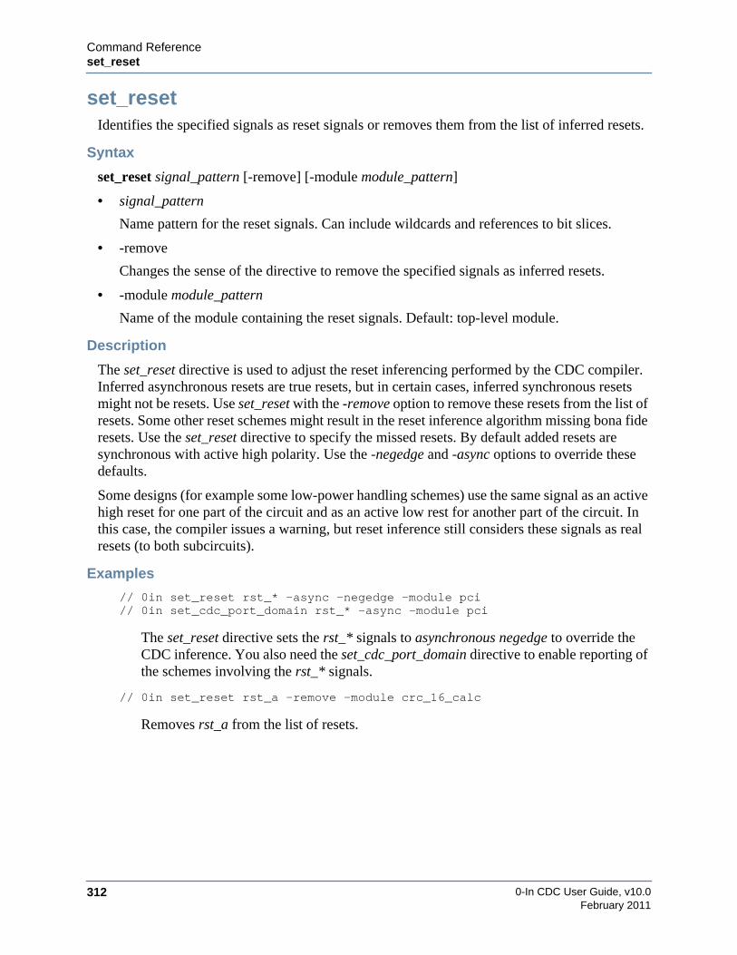
0-In CDC User Guide, v10.0312
Command Referenceset_reset
February 2011
set_resetIdentifies the specified signals as reset signals or removes them from the list of inferred resets.
Syntax
set_reset signal_pattern [-remove] [-module module_pattern]
• signal_pattern
Name pattern for the reset signals. Can include wildcards and references to bit slices.
• -remove
Changes the sense of the directive to remove the specified signals as inferred resets.
• -module module_pattern
Name of the module containing the reset signals. Default: top-level module.
Description
The set_reset directive is used to adjust the reset inferencing performed by the CDC compiler.Inferred asynchronous resets are true resets, but in certain cases, inferred synchronous resetsmight not be resets. Use set_reset with the -remove option to remove these resets from the list ofresets. Some other reset schemes might result in the reset inference algorithm missing bona fideresets. Use the set_reset directive to specify the missed resets. By default added resets aresynchronous with active high polarity. Use the -negedge and -async options to override thesedefaults.
Some designs (for example some low-power handling schemes) use the same signal as an activehigh reset for one part of the circuit and as an active low rest for another part of the circuit. Inthis case, the compiler issues a warning, but reset inference still considers these signals as realresets (to both subcircuits).
Examples
// 0in set_reset rst_* -async -negedge -module pci// 0in set_cdc_port_domain rst_* -async -module pci
The set_reset directive sets the rst_* signals to asynchronous negedge to override theCDC inference. You also need the set_cdc_port_domain directive to enable reporting ofthe schemes involving the rst_* signals.
// 0in set_reset rst_a -remove -module crc_16_calc
Removes rst_a from the list of resets.

Command ReferenceDirectives for Checker Generation
0-In CDC User Guide, v10.0 313February 2011
Directives for Checker GenerationGlobal directives for checker generation (Table 6-3) control in particular how the promotedCDC checkers and the generated CDC-FX checkers are configured. In general, they controlhow simulation with assertions and formal verification of assertions operate.
Table 6-3. Global Directives for Checker Generation
Directive Description Wildcard Args
default_reset Specifies a default signal for the reset inputs tocheckers.
-module
use_synthesis_case_directives Directs the compilers to recognize non-0incase directives (for example full and parallelcase directives).
-module
exclude_checker Specifies checkers to exclude from simulationwith assertions and formal analysis.
-type-name-module-group
include_checker Specifies checkers to include for simulationwith assertions and formal analysis.
-type-name-module-group
disable_checker Identifies a signal that can disable checkersduring simulation.
-type-name-module
disable_used Overrides the –used options for all checkers ofa given checker type in a module.
-type-module
set_severity Overrides the severity levels if any arespecified in the checker directives.
-type-name-module
set_checker_action Specifies the action to perform when thenumber of firings of checkers with the given-severity reaches the specified count. Directiveonly applies to assertions in simulation.
-module
checker_firing_keyword Specifies the keyword used in the firingmessages for checkers with the specifiedseverity level.
create_wire Creates a wire in checker logic.

0-In CDC User Guide, v10.0314
Command Referencechecker_firing_keyword
February 2011
checker_firing_keywordSpecifies the keyword used in the firing messages for checkers.
Syntax
checker_firing_keyword –name keyword_string [–severity level]
• -name "keyword_string"
String to insert into firing messages.
• -severity level
Severity level (0 - 9) of checkers that are to have the specified keyword string added to theirfiring messages. Default: keyword_string is added to all checker messages.
Description
By default, each checker firing message begins with:
0-In Firing:...
The checker_firing_keyword directive adds a specified keyword string to checker firingmessages:
0-In keyword_string Firing:...
The -severity level option restricts the directive to checkers with matching severity level.
Example
//0in checker_firing_keyword -name "Warning S4" -severity 4
Produces the following firing entry:
0-In Warning S4 Firing: S4 assert_window tb.U1...Devsel (Firing: 1)Time: 330sMessage: Ensures that signals assert correctly relative to a
specified multiple-cycle time windowSignature: One or more signals that should not have asserted
outside the window did assert.Module: pci_slv,File: /examples/pci_slave/checker_control.v,Line: 14Directive: awin -start Devsel -stop_count 2 -in Trdy -not_out
Trdy -module pci_slv -severity 4Check: ’not_out’
0-In End Firing

Command Referencecreate_wire
0-In CDC User Guide, v10.0 315February 2011
create_wireCreates a wire to use with assertion logic.
Syntax
create_wire -var wire [-width width] [-module module]
• -var wire
Name to give the created wire.
• -width width
Number of bits in the wire. Default: 1.
• -module module
Create the wire in the specified module. Default: wire is created in the current module.
Description
The create_wire global directive creates a wire in the current or specified module, for use inassertion logic. Wires created by this directive have the following limitations:
• Can only be driven by checker outputs.
• Can only be used as input to other checkers.
• Cannot be referenced hierarchically (in the design and in directive arguments).
• Cannot have the same name as an existing design signal name.
Examples
Following example creates a wire inside the module containing the create_wire directive.
module dut(in, clk, out);parameter P1 = 3;input [P1-1:0] in;input clk;output [P1-1:0] out;
// 0in set_clock clk -default
// 0in create_wire -var w -width P1// 0in create_assign -var (~out) -var_out w// 0in one_hot -var w
endmodule
Following example creates a wire inside the specified module.
module ctrl;// 0in create_wire -var w -width P1 -module dut// 0in create_assign -var (~out) -var_out w -module dut// 0in one_hot -var w -module dut// 0in create_wire -var f0 -module dut// 0in assert -var (out !=0) -assert_fire f0 -module dut
endmodule

0-In CDC User Guide, v10.0316
Command Referencedefault_reset
February 2011
default_resetSpecifies a default checker reset signal or activates default reset inference. Can be specified in adesign module.
Syntax
Identify Default Reset
default_reset {-none | signal [-active_high | -active_low]}[-sync | -async] [-infer] [-module module]
• signal | -none
Signal to be used as the default reset signal for checkers. The signal is taken to be a signal inmodule. If module is not specified, you must specify the full hierarchical path to signal.
• -active_high | -active_low
Polarity of the reset signal. Checker resets are active-high polarity, so specifying-active_high connects the signal directly and specifying -active_low inverts the signalbefore connecting. Default: -active_high.
• -sync | -async
Checker reset port: reset (-sync) or areset (-async). Typically, only one type of reset is usedfor the design and the other checker reset ports are tied to zero. Default: -sync
• -infer
Infers the reset for each checker and only uses signal if the inference is not successful. Thisoption can reduce ccl checker (i.e., simulation) compilation performance. Default: noinference.
• -module module
Module name or wildcard pattern (pattern must match exactly one module). Default:checkers in all modules (if specified in a control file) or the current module (if specified in asource code module).
Activate Default Reset Inference
default_reset -infer [-sync | -async | -sync -async] [-module module]
• -infer
Infers the reset for each checker and uses 1’b0 if the inference is not successful. This optioncan reduce checker (i.e., simulation) compilation performance. Default: no inference.
• -sync | -async | -sync -async
Checker reset ports: reset (-sync), areset (-async) or both. Typically, only one type of reset isused for the design and the other checker reset ports are tied to zero. Default: -sync

Command Referencedefault_reset
0-In CDC User Guide, v10.0 317February 2011
• -module module
Module name or wildcard pattern (pattern must match exactly one module). Default:checkers in all modules (signal must be a hierarchical path).
Description
Checker reset signals are not used by the SVA and PSL checkers, and they are explicitlyidentified in the instantiations of OVL and QVL checkers. CheckerWare checkers have tworeset ports: reset (synchronous) and areset (asynchronous). Connection to these ports can bespecified in the checker directive for a checker with the -reset and -areset arguments. Whenboth connections are not specified, the missing connections are determined from thespecification of default_reset global directives and by reset signal inference.
Inferring reset connections (and similarly clock connections) can be expensive in terms of lowercompilation performance.
The default_reset directive has two basic uses and the syntax depends on the usage:
• Identifies a default reset signal for CheckerWare checkers.
A specific reset signal is provided as the default reset for checkers in the DUT or for aparticular module. The -active_low option inverts the signal before connecting. The-sync or -async option identifies which reset ports to connect. The -infer option directsthe compiler to try to infer the connection before assigning the default reset.
• Activates the inference of default resets.
By default, if a connection to a checker reset port is not covered by an explicit checkerdirective (i.e., -reset signal or -areset signal argument) or by a default_reset signalglobal directive, then the reset port is connected to 1’b0. Specifying the inferenceactivation form of the default_reset directive directs the compiler to try to infer theconnection before assigning 1’b0.
NoteThe default_reset directives identify reset signals for CheckerWare directives only. Toproperly detect async_reset and async_reset_no_sync CDC schemes, you must identifythe reset signals with the set_reset directive.

0-In CDC User Guide, v10.0318
Command Referencedisable_checker
February 2011
disable_checkerIdentifies a signal that can disable checkers during simulation.
Syntax
disable_checker signal [–severity level] [–name checker] [–type type][–module module [–local]]
Arguments
• signal
Signal to use to disable matching checkers.
• -severity level
Severity level of checkers to disable with signal. Default: all levels.
• -name checker
Checker name or wildcard pattern. Default: *.
• -type type
Checker type or wildcard pattern. Default: *.
• -module module
Module name or wildcard pattern. Default: all modules.
• -local
Restrict the directive to checkers in the top-level of module. Default: module hierarchy.
Description
The disable_checker global directive specifies a signal that dynamically disables specifiedcheckers during simulation. When ccl synthesizes a checker, it derives the signal to connect tothe checker’s active input from the AND of the inverted disabling signal, any activationcondition (<), if specified and any –active option signal, if specified.

Command Referencedisable_used
0-In CDC User Guide, v10.0 319February 2011
disable_usedDisables the -used option of CheckerWare checkers of a given type.
Syntax
disable_used -type type [-module module [-local]]
• -type type
Checker type or wildcard pattern.
• -module module
Module name or wildcard pattern. Default: all modules.
• -local
Restricts the directive to checkers in the top-level of module. Default: module hierarchy.
Description
Overrides the -used option of CheckerWare checkers that have the specified checker type. The-used option constrains a checker to fire only if at least one downstream register samples at leastone bit of the value on the element being checked (this constraint is called the used_condition).In general, used_condition is composed of the conditions in which downstream registers load avalue, and the muxing/combinational logic (between the downstream registers and the elementbeing checked) is turned on to allow the value to flow through combinationally to thedownstream registers.
Example
//0in disable_used -type one_hot
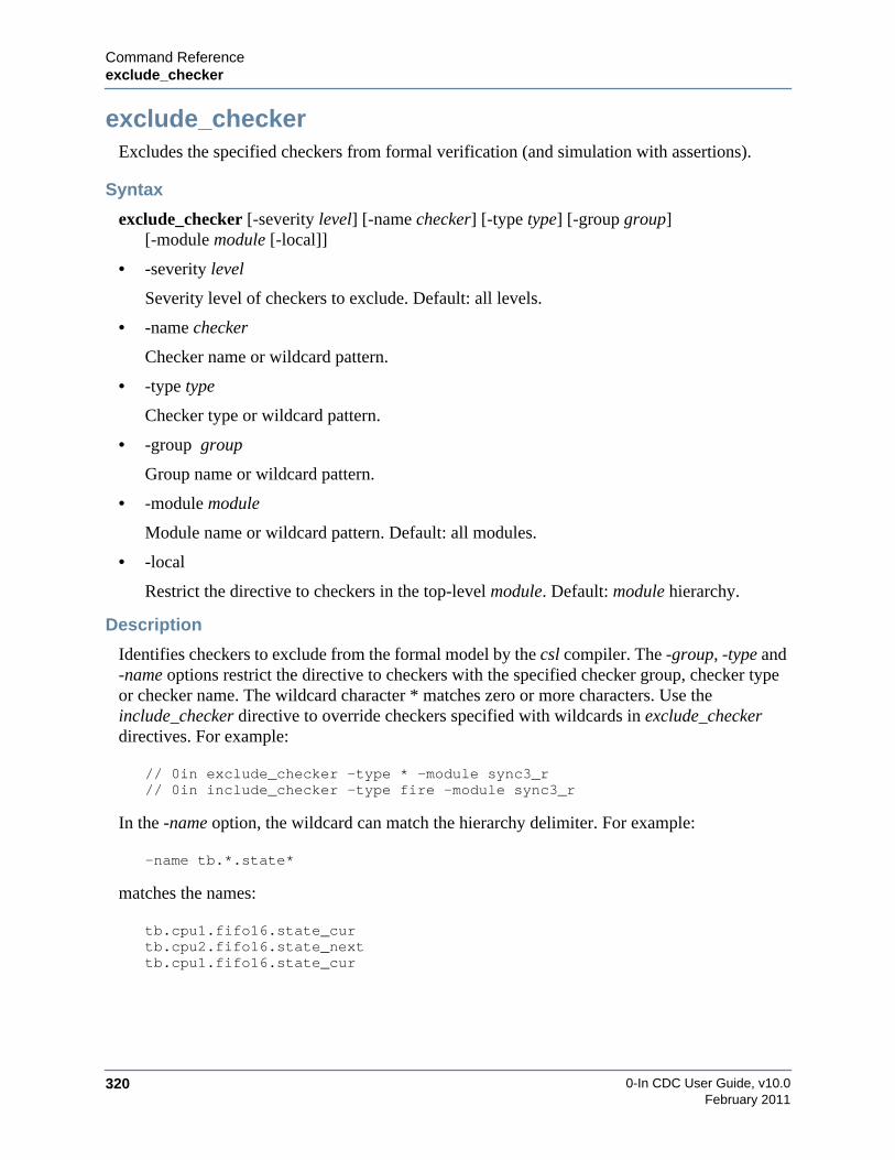
0-In CDC User Guide, v10.0320
Command Referenceexclude_checker
February 2011
exclude_checkerExcludes the specified checkers from formal verification (and simulation with assertions).
Syntax
exclude_checker [-severity level] [-name checker] [-type type] [-group group][-module module [-local]]
• -severity level
Severity level of checkers to exclude. Default: all levels.
• -name checker
Checker name or wildcard pattern.
• -type type
Checker type or wildcard pattern.
• -group group
Group name or wildcard pattern.
• -module module
Module name or wildcard pattern. Default: all modules.
• -local
Restrict the directive to checkers in the top-level module. Default: module hierarchy.
Description
Identifies checkers to exclude from the formal model by the csl compiler. The -group, -type and-name options restrict the directive to checkers with the specified checker group, checker typeor checker name. The wildcard character * matches zero or more characters. Use theinclude_checker directive to override checkers specified with wildcards in exclude_checkerdirectives. For example:
// 0in exclude_checker -type * -module sync3_r// 0in include_checker -type fire -module sync3_r
In the -name option, the wildcard can match the hierarchy delimiter. For example:
-name tb.*.state*
matches the names:
tb.cpu1.fifo16.state_curtb.cpu2.fifo16.state_nexttb.cpu1.fifo16.state_cur

Command Referenceinclude_checker
0-In CDC User Guide, v10.0 321February 2011
include_checkerIncludes the specified checkers in the formal model and checker compilation.
Syntax
include_checker [-severity level] [-name checker] [-type type] [-group group][-module module [-local]]
• -severity level
Severity level of checkers to include. Default: all levels.
• -name checker
Checker name or wildcard pattern.
• -type type
Checker type or wildcard pattern.
• -group group
Group name or wildcard pattern.
• -module module
Module name or wildcard pattern. Default: all modules.
• -local
Restricts the directive to checkers in the top-level module. Default: module hierarchy.
Description
Identifies checkers to compile by the ccl/csl compiler even if they are specified in anexclude_checker directive. The -group, -type and -name options restrict the directive tocheckers with the specified checker group, checker type or checker name. The wildcardcharacter * matches zero or more characters. Use the include_checker directive to overridecheckers specified with wildcards in exclude_checker directives. For example:
// 0in exclude_checker -type * -module sync3_r// 0in include_checker -type fire -module sync3_r
In the -name option, the wildcard can match the hierarchy delimiter. For example:
-name tb.*.state*
matches the names:
tb.cpu1.fifo16.state_curtb.cpu2.fifo16.state_nexttb.cpu1.fifo16.state_cur

0-In CDC User Guide, v10.0322
Command Referenceset_checker_action
February 2011
set_checker_actionSpecifies the action to perform when the number of simulation firings of checkers having agiven severity level reaches the specified count.
Syntax
set_checker_action [-count count ] [-stop | -finish] [-severity level] [-module module]
• -count count
Total number of firings for all checkers of the specified severity. When the number offirings of the specified severity reaches this count, the simulation performs the specifiedaction of -stop or -finish.
• -stop
Stop the simulation, but you can restart the session.
• -finish
End the simulation. By default, the simulation ends 10 time units after the last firing. Usethe +0in_checker_finish_delay+time ccl option to change this default.
• -severity level
The directive specifies a single severity level (positive digit 0 to 9) and an optional count.Severity level 0 sets the default checker action.
• -module module
Restrict the global directive to checkers in the specified module.
Description
Each set_checker_action global directive specifies the action to perform when the number offirings of checkers having a given severity level reaches the specified count. This directive onlyapplies to simulation.
Command Referenceset_severity
0-In CDC User Guide, v10.0 323February 2011
set_severityAssigns a severity level to specified checkers.
Syntax
set_severity[-severity level [-default]] [-name checker_pattern] [-type type_pattern][-module module_pattern [-local]]
• -severity level
Severity level to assign to matching checkers (0 - 9). Default: no severity.
• -default
Restricts the directive to checkers that have default severity. CheckerWare checkers that donot have a -severity level argument in the original checker directive have default severity.PSL and SVA checkers also have default severity.
• -name checker_pattern
Checker name or wildcard pattern.
• -type type_pattern
Checker type or wildcard pattern.
• -module module_pattern
Module name or wildcard pattern. Default: all modules.
• -local
Restricts the directive to checkers in the top-level module. Default: module hierarchy.
Description
Overrides the severity level of specified checkers. A checkers can have no severity (called thedefault severity) or it can have a value in the range 0 to 9 assigned as its severity level. Rankingis up to you (default might have “level” 0 or “level” 10). Severity levels are used primarily insimulation with assertions to affect the simulator response to checker firings.
Example
The following directives exclude psl and decrement checkers.
// 0in set_severity -severity 7 -type psl// 0in set_severity -severity 7 -type decrement// 0in exclude_checker -severity 7
0-In CDC User Guide, v10.0324
Command Referenceuse_synthesis_case_directives
February 2011
use_synthesis_case_directivesCreates case checkers for matching non-native (e.g., synthesis) case directives.
Syntax
use_synthesis_case_directives[-min_width width] [-min_item_count count][-max_width width] [-max_item_count count][-used] [-module module [-local]]
• -min_width width
Minimum width of the case switch.
• -min_item_count count
Minimum number of case items in the statement.
• -max_width width
Maximum width of the case switch.
• -max_item_count count
Maximum number of case items in the statement.
• -used
Adds the -used argument to the generated case checkers. A generated case checker can fireonly when at least one bit of a variable assigned in the active case block is loaded into adestination register.
• -module module
Module name or wildcard pattern. Default: all modules.
• -local
Restricts the directive to checkers in the top-level module. Default: module hierarchy.
Description
Creates case checkers for non-native case directives in the HDL code. These are directives ofthe following form:
// product [full_case] [parallel_case]
Where product indicates the identifier for the non-native synthesis product (for example,“synopsys” or “synthesis”).

Command ReferenceShell Commands
0-In CDC User Guide, v10.0 325February 2011
Shell CommandsThree types of shell commands are used in CDC analysis:
• Compiler commands — The 0-In/Questa design compiler commands handle front-endcompilation of the design logic for CDC analysis. Questa and 0-In tools support thesame design styles and HDL constructs.
• The vlib command sets up the working library for compiling the design units forCDC analysis.
• The vmap command maps logical library names to physical directories.
• The vcom command compiles VHDL source files.
• The vlog command compiles Verilog (and SystemVerilog) source files.
• The verror command reports additional detail for messages.
• The vdir command reports information about design units in libraries.
• The vdel command deletes design units from libraries.
• 0in shell — The compilation environment for CDC, the 0-In formal tools and 0-Inassertions in simulation is controlled from a special verification command shell calledthe 0in shell, invoked from the system shell by the 0in shell command.
• CDC GUI — The 0in_cdc command runs the CDC GUI.
• Simulation commands — The ccl 0in shell command generates the assertion logic forsimulation with assertions. Using the data generated by ccl and a set of simulation-timesimulator arguments, you run simulation with assertions using a native(Questa/ModelSim) simulator or a third-party simulator (VCS/NC-Verilog).
0-In CDC User Guide, v10.0326
Command Referencevlib
February 2011
vlibCreates a design library for use by vmap/vcom/vlog, and sets accessibility to design units in alibrary (or to the entire library).
Syntax
vlib[-locklib | -unlocklib] [{-lock | -unlock} design_unit]… library
• -locklib
Locks the library so the library cannot be overwritten by the compilers.
• -unlocklib
Unlocks the library so the library can be overwritten by the compilers.
• {-lock | -unlock} design_unit
Locks/unlocks the specified design unit (module) in the library so it cannot be refreshed orrecompiled. File permissions are not affected by these switches
• library
Name to identify the library. The name work is the default working library: a library workstatement is not needed in the source and work is the default destination of compiled units(so work need not be mapped). Must be the last argument.
Description
Two types of design libraries are used with the Questa tools:
• resource libraries
Static libraries used by the source code for your design. Pre-compiled resource librariesare typically supplied by a third party (for example, models of gate-level netlists) oranother design team. But, you also can specify resource libraries when compiling thedesign (after using vlib to create the library). For a Verilog library, use the -L option tovlog. For a VHDL library, use the -work library option to vcom to specify the libraryname for the compiled VHDL resource library, so it is not saved as the work library.Within a VHDL source file, use a VHDL library clause to specify names of resourcelibraries referenced in the design unit.
• working library
Dynamic library containing executable code, debug information, dependencyinformation and other data for compiling a design. Only one library is the workinglibrary for analyzing a design. The library named work is the default assumed workinglibrary. But, you still must use vlib to create the working library:
system prompt> vlib work
Command Referencevmap
0-In CDC User Guide, v10.0 327February 2011
vmapCreates a logical-to-physical mapping for a design library, removes logical-to-physicalmappings or reports current mappings
Syntax
vmap[-modelsimini init_file [-c]] [logical_name [dir] | -del logical_name…]
• -modelsimini init_file
Add the mapping to the compiler initialization file init_file. Default: ./modelsim.ini (copiedfrom the distribution software if ./modelsim.ini does not exist.
• -c
Copy init_file to ./modelsim.ini and add the mapping to ./modelsim.ini. However, if./modelsim.ini exists and is write-protected, add the mapping to init_file instead.
• logical_name
Name to map or un-map. Default: reports the current logical-to-physical mappings (frommodelsim.ini).
• dir
Physical directory to which the logical name should map. Default: prints the current logical-to-physical mapping for logical_name.
• -del logical_name…
Un-map the logical-to-physical mappings for the specified logical_name list.
Description
The vlib command creates a design library with a given logical name and stores the libraryinformation in a directory with the same name in the current directory. By default, the libraryname is mapped to the directory name. The vmap command is used to change this logical-to-physical mapping and to manage logical-to-physical mappings. Non-default logical-to-physicalmappings are stored in the modelsim.ini file in the current directory.
Examples
Example 1
system prompt> vmap
Reports the current mappings.
Example 2
system prompt> vmap work
Reports the current mapping for the work library.

0-In CDC User Guide, v10.0328
Command Referencevmap
February 2011
Example 3
system prompt> vmap work ../shiba/my_workCopying path/modelsim.ini to modelsim.iniModifying modelsim.ini
Maps the work library to ../shiba/my_work. Copies modelsim.ini from the software installationto the current directory and adds the mapping to ./modelsim.ini.
Example 4
system prompt> vmap -modelsimini ../shiba/modelsim.ini \work ../shiba/my_workModifying ../shiba/modelsim.ini
Maps the work library to ../shiba/my_work and adds the mapping to ../shiba/modelsim.ini.
Example 5
system prompt> lsworksystem prompt> vmap -modelsimini -c ../shiba/modelsim.ini \work ../shiba/my_workCopying ../shiba/modelsim.ini to modelsim.iniModifying modelsim.ini** Warning: Copied ../shiba/modelsim.ini to modelsim.ini. Updated modelsim.ini. MODELSIM set to ../shiba/modelsim.ini.
The MODELSIM environment variable is used to find the modelsim.ini file, so this local copy will not be used.
Maps the work library to ../shiba/my_work, copies ../shiba/modelsim.ini to ./modelsim.ini andadds the mapping to ./modelsim.ini.
Example 6
system prompt> lsmodelsim.ini worksystem prompt> chmod a-w modelsim.inisystem prompt> vmap -modelsimini -c ../shiba/modelsim.ini \work ../shiba/my_workCopying ../shiba/modelsim.ini to modelsim.ini** Error: (vmap-7) Failed to open ini file "modelsim.ini" in write mode.Permission denied. (errno = EACCES)Modifying ../shiba/modelsim.ini** Warning: vmap will not overwrite local modelsim.ini. MODELSIM set to ../shiba/modelsim.ini. ../shiba/modelsim.ini was modified because copy failed
The MODELSIM environment variable is used to find the modelsim.ini file, so this local copy will not be used.
Maps the work library to ../shiba/my_work and adds the mapping to ./modelsim.ini.

Command Referencevmap
0-In CDC User Guide, v10.0 329February 2011
Example 7
system prompt> vmap -del workRemoving reference to logical library workModifying modelsim.ini
Un-maps any existing mapping for the work library and restores the mapping to the defaultdirectory for the library (./work).
Example 8
system prompt> vmap -del ZLIB YLIBRemoving reference to logical library ZLIBModifying modelsim.iniRemoving reference to logical library YLIBModifying modelsim.ini
Un-maps any existing mappings for the ZLIB and YLIB libraries and restores the mappings tothe default directories (./ZLIB and ./YLIB).

0-In CDC User Guide, v10.0330
Command Referencevcom
February 2011
vcomCompiles VHDL source files into a design or resource library.
Syntax
vcom[-version] [-work logical_name] [–modelsimini init_file] [-87 | -93 | -2002 | -2008][-explicit] [–skipsynthoffregion [–synthprefix keyword]] [-check_synthesis][-noindexcheck | -norangecheck | -nocheck][{-fatal | -error | -warning | -note | -suppress} msg_number [,msg_number]…]…[-source] [-time] [-nowarn number]… [-quiet] [-mixedsvvh [b | l | r] [i]][-pslfile vunit_file]… [-f arg_file]… [other_vcom_options] VHDL_file…
• -version
Report the Questa version and exit.
• -work logical_name
Name of the design library to use as the destination for the compilation. Default: work.
• –modelsimini init_file
Load init_file as the initialization (modelsim.ini) file. Default: search path shown inFigure 3-4 on page 59.
• -87 | -93 | -2002 | -2008
VHDL version: VHDL-87, VHDL-93, VHDL-2002 or VHDL-2008. Default: valuespecified by the VHDL93 variable (default 2002) in modelsim.ini.
• -explicit
Resolve ambiguous function overloading in favor of the explicit definition. Default: valuespecified by the Explicit variable (default on) in modelsim.ini. Having Explicit set inmodelsim.ini makes the compiler compatible with common industry practice. Commentingout Explicit favors implicit definitions, which matches the VHDL standard.
• -skipsynthoffregion
Do not parse synthesis off and translate off regions of HDL code. Keywords for synthesisoff/on and translate off/on pragmas are: pragma, synthesis, synopsys, 0in, mentor, mspa, mtiand vcs, plus custom keywords specified with the -synthprefix keyword argument. Default:HDL code in synthesis off and translate off regions is parsed and made ready for use insimulation and 0-In analysis.
Use this option to avoid parsing synthesis/translate off region code that might besyntactically or semantically incorrect. However, if you specify -skipsynthoffregion, thedesign library is not suitable for simulation. Therefore, Questa simulator users should try toavoid using this option.

Command Referencevcom
0-In CDC User Guide, v10.0 331February 2011
• –synthprefix keyword
Synthesis off/on pragma keyword. Treat code in <keyword> synthesis_off /synthesis_onregions and <keyword> translate_off /translate_on regions as “parse and ignore”. Forexample if you specify -synthprefix zin, the following synthesis off regions of code areparsed and ignored.
-- zin synthesis_offVDHL code to parse and ignore
-- zin synthesis_on
// zin translate_offVerilog code to parse and ignore
// zin translate_on
Default synthesis off/on keywords: pragma, synthesis, synopsys, 0in, mentor, mspa, mtiand vcs.
• -check_synthesis
Perform limited synthesis rule checks (for example, process signals are in the process’sensitivity list). Default: value specified by the CheckSynthesis variable (default off) inmodelsim.ini.
• -noindexcheck | -norangecheck | -nocheck
Do not check that indexes are in bounds (-noindexcheck); do not check that scalar values aredefined in their ranges (-norangecheck); or do not perform either of these checks(-nocheck). These options can speed up compilation of large designs. Default: valuesspecified by the NoIndexCheck and NoRangeCheck variables (default off, i.e., checkingenabled) in modelsim.ini.
• {-fatal | -error | -warning | -note | -suppress} msg_number [,msg_number]…
Change the severity of the specified messages. You cannot suppress fatal (or internal)messages. Default: severities set in the [msg_system] section of modelsim.ini, whichoverrides the default settings from the compiler.
• -source
Include corresponding source code line numbers in messages.
• -time
Report the process time (actual time, not CPU time) taken for the compilation.
• -nowarn number
Do not report warning messages for number category:
1 unbound component 8 lint checks2 process without a wait statement 9 signal value dependency at elaboration3 null range 10 VHDL-93 constructs in VHDL-87 code4 no space in time literal 11 PSL warnings5 multiple drivers on unresolved signal 13 constructs that coverage cannot handle
0-In CDC User Guide, v10.0332
Command Referencevcom
February 2011
• -quiet
Do not report loading messages.
• -mixedsvvh [b | l | r] [i]
Compile VHDL packages so they can be included in a SystemVerilog design. Qualifiershave the following meanings:
Default: see VHDL to SystemVerilog Data Types Mapping.
• -pslfile vunit_file
PSL VHDL flavor vunit file to bind and compile. Vunits must be compiled at the same timeas the design units to which they are bound.
• -f arg_file
File containing additional command arguments. Argument files have the following syntaxrules:
• newlines — treated as spaces.
• // — text to the end of the line is ignored.
• /* text */ — text (including newlines) is ignored.
• single quotes (‘text’) — groups text and prevents character substitution (such as variableexpansion and character escapes).
• double quotes (“text”) —groups text and prevents character substitution except forbackslash escape and environment variable substitution. For example:
// groups argument with spaces and substitutes value for $TIME_UNIT-timescale "$TIME_UNIT / 1 ps"
• environmental variables — are expanded unless preceded by a backslash (for example,\$USER) or in single quotes (for example, ‘$USER’).
• -f arg_file — can be nested inside an argument file.
• other_vcom_options
Options only relevant to simulation do not affect the 0-In compilers. Other advanced optionsmight affect 0-In tool results—these are described in the Questa documentation.
6 VITAL compliance checks 14 locally static error deferred until7 VITAL optimization messages
b scalars and vectors have SystemVerilog bit typel scalars and vectors have SystemVerilog logic typer scalars and vectors have SystemVerilog reg typei ignore the ranges specified with VHDL integer types

Command Referencevcom
0-In CDC User Guide, v10.0 333February 2011
• VHDL_file…
Files containing VHDL source code to compile. Wildcards are supported (e.g., *.vhd).Design units are compiled in the order they appear.
Description
The vcom command compiles one or more VHDL source files into a design library. Beforeusing this command, use the vlib command to create the initial design library. Subsequentapplications of vcom can be used to incrementally compile and recompile the VHDL portion ofthe design. For VHDL, compile order is important. You must compile entities andconfigurations before architectures that reference them.
Examples
Example 1
system prompt> vcom dut.vhd
Compiles dut.vhd into the work library.
Example 2
system prompt> vcom -work my_work block1.vhd block2.vhd top.vhd
Compiles block1.vhd, block2.vhd and top.vhd (in that order) into the my_work library.
Example 3
system prompt> vlib worksystem prompt> vcom -2008 block1.vhdsystem prompt> vcom block2.vhd top.vhd
Creates a work library; compiles the VHDL-2008 flavor block1.vhd file; then compiles theVHDL-2002 (default) flavor block2.vhd and top.vhd files.
0-In CDC User Guide, v10.0334
Command Referencevlog
February 2011
vlogCompiles Verilog source files into a design or resource library.
Syntax
vlog[–version] [–work logical_name] [–libmap library_map_file [–libmap_verbose]][–modelsimini init_file] [{–Lf | –L } library]… [–vlog95compat | –vlog01compat][–skipsynthoffregion [–synthprefix keyword]] [–skipprotected | –skipprotectedmodule][–pedanticerrors] [–timescale units/precision] [+define{+macro[=value}…][–convertallparams] [+floatparameters[+param_path[.]]][+incdir{+include_dir}…] [+libext{+extension}…] [–printinfilenames][{–fatal | –error | –warning | –note | –suppress} msg_number [,msg_number]…]…[–source] [–time] [–nowarnID | –nowarn number]… [–quiet] [–93] [–u] [–sv][–mixedsvvh [b | s | v] [packedstruct]] [–mfcu [–cuname comp_unit] | –sfcu][–pslfile vunit_file]… [–y library_dir] [–v library_file] [–f arg_file]…[other_vlog_options] Verilog_file…
• –version
Report the Questa version and exit.
• –work logical_name
Name of the library to use as the destination for the compilation. Default: work.
• –libmap library_map_file
Verilog 2001 logical-to-physical library map file.
• –libmap_verbose
Report library map pattern matching information to troubleshoot problems with matchingfilename patterns in the library file.
• –modelsimini init_file
Load init_file as the initialization (modelsim.ini) file. Default: search path shown inFigure 3-4 on page 59.
• –Lf library | –L library
Resource library containing pre-compiled modules for the compilation. With the –Lfargument, library is searched before searching in the effective ‘uselib library (if specified)for the instantiation. With the –L argument, library is searched after searching the effective‘uselib library. The LibrarySearchPath variable defines an initial resource library searchpath. When searching for a module for an instantiation, the libraries specified byLibrarySearchPath are searched in (left-to-right) order, as if they were specified with the –Largument. If no match is found, the libraries specified in the –Lf and –L options are searchedin the order specified in the command invocation.

Command Referencevlog
0-In CDC User Guide, v10.0 335February 2011
• –vlog95compat | –vlog01compat
Assume the IEEE 1364-1995 standard (-vlog95compat) or the IEEE 1364-2001 standard(-vlog01compat). These two Verilog standards have some conflicts, so running the correctcompatibility ensures valid code is compiled properly. Default: value specified by thevlog95compat variable (default off, i.e., 2001) in modelsim.ini.
• -skipsynthoffregion
Ignore (do not parse or compile) synthesis off and translate off regions of HDL code.Keywords for synthesis off/on and translate off/on pragmas are: pragma, synthesis,synopsys, 0in, mentor, mspa, mti and vcs, plus custom keywords specified with the -synthprefix keyword argument. Default: HDL code in synthesis off and translate off regionsis parsed and compiled, ready for use in simulation and 0-In analysis. If you specify -skipsynthoffregion, the design library might not be suitable for simulation.
• –synthprefix keyword
Synthesis off/on pragma keyword. Skip (i.e., ignore and do not parse) code in <keyword>synthesis_off regions and <keyword> translate_off regions. For example if you specify-synthprefix zin, the following regions of code are ignored.
-- zin synthesis_offVDHL code to ignore
-- zin synthesis_on
// zin translate_offVerilog code to ignore
// zin translate_on
Default synthesis off/on keywords: pragma, synthesis, synopsys, 0in, mentor, mspa, mti andvcs.
• –skipprotected
Ignore (do not parse or compile) protected regions of HDL code. Default: compile codeinside protected/endprotected regions.
• –skipprotectedmodule
Exclude modules containing protected/endprotected regions from being added to thelibrary. Declarations are preserved (for both –skipprotectedmodule and –skipprotected). Forexample:
module test(input in, output out);‘protected reg tmp; ‘endprotectedassign out = tmp && in;
endmodule
prompt> vlog test.v -skipprotected-- Compiling module test** Warning: test.v(2): (vlog-2280) Skipping protected region.
The module compiles OK—no undefined variable (tmp) error occurs. Default: modulescontaining protected regions are compiled and added to the library.

0-In CDC User Guide, v10.0336
Command Referencevlog
February 2011
• –pedanticerrors
Report mismatched ‘else directives and enforce the following IEEE Verilog Standard 1800-2005 restrictions:
• new for queues is illegal. Default: new creates a queue whose elements are initializedto the default value of the queue element type.
• Sized, based literals containing underscore characters (for example, 8’b0110_0110)are illegal. Default: these constructs are legal.
• Class extern method prototypes with lifetime (automatic/static) designations areillegal. Default: these constructs generate LRM-compliance warnings.
• PSL statements with cover bool@clk constructs are illegal. Default: these constructsare legal.
• –timescale units/precision
Default timescale for modules. Precision must be units and both units and precision havethe form:
{1 | 10 | 100}{fs | ps | ns | us | ms | s}
For example: –timescale 10ns/100ps.
• +define{+macro[=value]}
Text macro specification. Overrides any matching ‘define compiler directives.
• –convertallparams
Compile non-ANSI parameters so they can be translated into std_logic_vector, bit_vector,std_logic, vl_logic, vl_logic_vector, and bit generics when interfacing with VHDL designunits.
• +floatparameters[+param_path[.]]
Do not evaluate specified parameters, so they can be overridden by -g/-G options to csl andvsim. The param_path is a module, module/parameter, hierarchical path to an instance, orhierarchical path to a parameter in an instance. Specifying a period (.) applies the argumentrecursively to instances in param_path. Default param_path: all parameters.
• +incdir+include_dir
Input include directory.
• +libext{+extension}…
File extensions to use when searching for library files. For example, +libext+.v
• –compile_uselibs[=uselib_dir]
Compile ‘uselib source files into uselib_dir directory and update modelsim.ini with thelogical-to-physical mappings for the uselib libraries. The ‘uselib directives are persistent:the last ‘uselib directive in a file applies to the rest of the code in the file—and to the code insubsequent files in the vlog invocation, up to the next ‘uselib directive. You can specify an

Command Referencevlog
0-In CDC User Guide, v10.0 337February 2011
empty ‘uselib directive at the end of a file to prevent the effect of the last ‘uselib directivefrom carrying over to the next file. Default ‘uselib directory: $MTI_USELIB_DIR (ifdefined) in the current directory, otherwise mti_uselibs in the current directory.
• –printinfilenames
Print the paths of all source files opened during the session, including include files.
• {–fatal | –error | –warning | –note | –suppress} msg_number [,msg_number]…
Change the severity of the specified messages. You cannot suppress fatal (or internal)messages. Default: severities set in the [msg_system] section of modelsim.ini, whichoverrides the default settings from the compiler.
• –source
Include corresponding source code line numbers in messages.
• –time
Report the process time (actual time, not CPU time) taken for the compilation.
• –nowarnID | –nowarn number
Do not report warning messages for ID or number category. ID is an identifier for a class ofmessages—it appears in square brackets in the message. For example, ID is RDGN in thefollowing message:
** Warning: test.v(15): [RDGN] - Redundant digits in numeric literal.
The argument to filter out RDGN warnings is: -nowarnRDGN. Warning category numbersidentify broad categories of messages:
• –quiet
Do not report loading messages.
• –93
Use VHDL-1993 extended identifiers when interfacing with VHDL design units, topreserve case in Verilog identifiers that contain upper-case letters.
• –u
Convert identifiers to upper case.
• –sv
Recognize SystemVerilog source code in all files. Default: SystemVerilog source code isrecognized only in files with .sv extensions.
11 PSL warnings 13 constructs that code coveragecannot handle
12 non-LRM compliance to matchalien simulator behavior
15 SystemVerilog assertions usinglocal variables
0-In CDC User Guide, v10.0338
Command Referencevlog
February 2011
• –mixedsvvh [b | s| v] [packedstruct]
Compile SystemVerilog packages so they can be included as packages in a VHDL design.Qualifiers have the following meanings:
Default: see SystemVerilog-to-VHDL Data Types Mapping.
• –mfcu
Compile the named source files into a single compilation unit (i.e., a multi-file compilationunit). Default: value specified by the MultiFileCompilationUnit variable (default off) inmodelsim.ini. If multi-file compilation units are not enabled, a compilation unit is createdfor each source file, which matches the SystemVerilog standard.
• –cuname comp_unit
Name to give the compilation unit created by -mfcu. Use this option if a module has a bindstatement, but no module in the design depends on the resulting compilation unit. In thiscase, the bind statement would not be elaborated by csl or vsim. For these tools, namingcomp_unit forces elaboration of the compilation unit package (including the bindstatement), which otherwise would not be elaborated. If specified, you must also specify thecomp_unit to csl/cdc (with the -cuname option). Though the vsim command accepts only asingle comp_unit name, csl/cdc accept multiple comp_unit names.
• –sfcu
Compile the named source files into individual compilation units (i.e., single-filecompilation units). Default: value specified by the MultiFileCompilationUnit variable(default off) in modelsim.ini. If MultiFileCompilationUnit is not set to 1, -sfcu is not needed.
• –pslfile vunit_file
PSL Verilog flavor vunit file to bind and compile. Vunits must be compiled at the same timeas the design units to which they are bound.
• –y library_dir
Directory containing library files.
• –v library_file
Library file.
• –f arg_file
File containing additional command arguments. Argument files have the following syntaxrules:
• newlines — treated as spaces.
• // — text to the end of the line is ignored.
b scalars and vectors are VHDL bit/bit_vector typess scalars and vectors are VHDL std_logic/std_logic_vector typesv scalars and vectors are VHDL vl_logic/vl_logic_vector typespackedstruct packed structures are VHDL arrays with equivalent sizes

Command Referencevlog
0-In CDC User Guide, v10.0 339February 2011
• /* text */ — text (including newlines) is ignored.
• single quotes (‘text’) — groups text and prevents character substitution (such as variableexpansion and character escapes).
• double quotes (“text”) —groups text and prevents character substitution except forbackslash escape and environment variable substitution. For example:
// groups argument with spaces and substitutes value for $TIME_UNIT-timescale "$TIME_UNIT / 1 ps"
• environmental variables — are expanded unless preceded by a backslash (for example,\$USER) or in single quotes (for example, ‘$USER’).
• –f arg_file — can be nested inside an argument file.
• other_vlog_options
Options only relevant to simulation (which do not affect the 0-In tools). Other advancedoptions might affect 0-In tool results—these are described in the Questa documentation.
• Verilog_file…
Files containing Verilog source code to compile. Wildcards are supported (e.g., *.v *.sv).
Description
The vlog command compiles one or more Verilog/SystemVerilog source files into a designlibrary. Before using this command, use the vlib command to create the initial design library.Subsequent applications of vlog can be used to incrementally compile and recompile theVerilog portion of the design.
Examples
Example 1
system prompt> vlog dut.v
Compiles dut.v into the work library.
Example 2
system prompt> vlog -work my_work block1.v block2.v top.sv
Compiles block1.v, block2.v and top.sv into the my_work library.
Example 3
system prompt> vlib worksystem prompt> vlog -vlog95compat block1.vhdsystem prompt> vcom block2.vhd top.vhd
Creates a work library; compiles the Verilog-95 flavor block1.v file; then compiles theVerilog-2001 (default) flavor block2.v and SystemVerilog top.sv files.
0-In CDC User Guide, v10.0340
Command Referenceverror
February 2011
verrorReports detailed information about Questa utility errors.
Syntax
verror[ –ranges | [[–fmt] [–tag] | –full] {message_number… | [–kind tool] -all} ]
• –ranges
Report the numeric ranges of message numbers for all tools. Numbers missing from theranges are invalid messages. For example, 126 is not in a range so verror 126 returns:
** Error: Invalid message number 126.
• –fmt, –tag, –full
Type of information to report for a message:
–fmt — format string for the message, for example:
Failed to access library ’%s’ at "%s".
–tag — message tag, for example:
MSG_IDX_LIBRARY_ACCESS_FAILED
Specify both –fmt and –tag to report the format string and the tag. Specify –full to report thisinformation plus a detailed message. Default: report the detailed message only.
• message_number…
List of message numbers. For example, the following vlog error message has messagenumber 19:
Vlog error.(vlog-19) Failed to access library ’work’ at "work".
Information is reported for each specified message number.
• –kind tool –all
Group of messages to report. The tool can be any of common, vcom, vcom-vlog, vlog, vsim,vsim-vish, wlf, vsim-sccom, sccom, vsim-systemc, ucdb, vsim-vlog or pseudo_synth. The –allargument is required. Default tool: messages for all tools are reported.
Description
Error/warning messages reported by Questa tools are terse. Use the verror command to getdetailed information about messages.
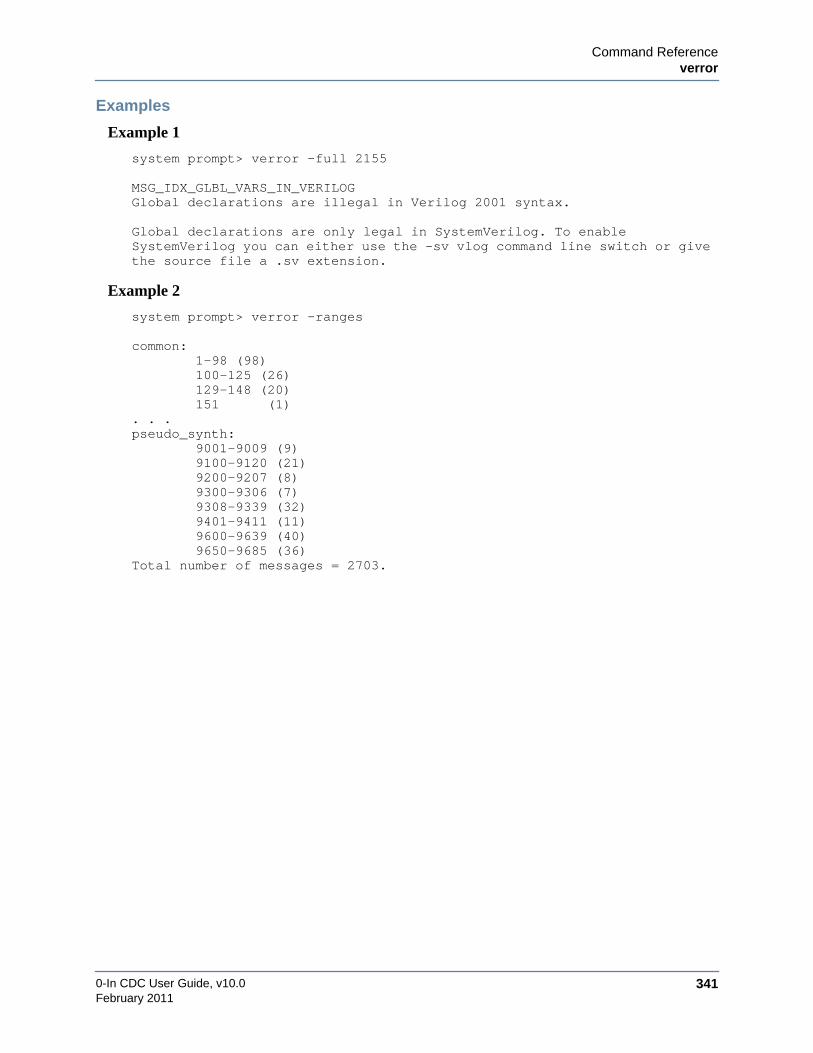
Command Referenceverror
0-In CDC User Guide, v10.0 341February 2011
Examples
Example 1
system prompt> verror -full 2155
MSG_IDX_GLBL_VARS_IN_VERILOGGlobal declarations are illegal in Verilog 2001 syntax.
Global declarations are only legal in SystemVerilog. To enableSystemVerilog you can either use the -sv vlog command line switch or givethe source file a .sv extension.
Example 2
system prompt> verror -ranges
common: 1-98 (98) 100-125 (26) 129-148 (20) 151 (1). . .pseudo_synth: 9001-9009 (9) 9100-9120 (21) 9200-9207 (8) 9300-9306 (7) 9308-9339 (32) 9401-9411 (11) 9600-9639 (40) 9650-9685 (36)Total number of messages = 2703.

0-In CDC User Guide, v10.0342
Command Referencevdir
February 2011
vdirReports information about the contents of a library.
Syntax
vdir[–prop id | –l] [–r] [–modelsimini file] [–all | [–lib library] [design_unit]]
• –prop id
Report the information specified by id for each design unit.
Default: no detailed information is reported.
• –l
Report all the information in the above table for each design unit.
• –r
Report the architectures for each VHDL entity.
• –modelsimini file
Use file as the modelsim.ini file to determine the library or libraries. Default: ./modelsim.ini.
• –all
Report information for all libraries. Default: library (or work) only.
• –lib library
Report information for library (logical or physical library). Default library: work.
• design_unit
Design unit to report. Default: all entities, configurations, modules, packages and optimizeddesign units.
id Information id Informationarchcfg Configuration for architecture mtime Source modified time
bbox Blackbox for optimized design name Short name
body Needs a body opcode Opcode format
default Compile defaults options Compile options
dir Source directory fulloptions Full compile options
dpnd Depends on root Optimized Verilog design root
entcfg Configuration for entity src Source file
extern Package reference number top Top-level model
inline Module inlined ver Version string
lock Design unit locked/unlocked vlogv Verilog version
lrm VHDL language standard voptv Verilog optimized version
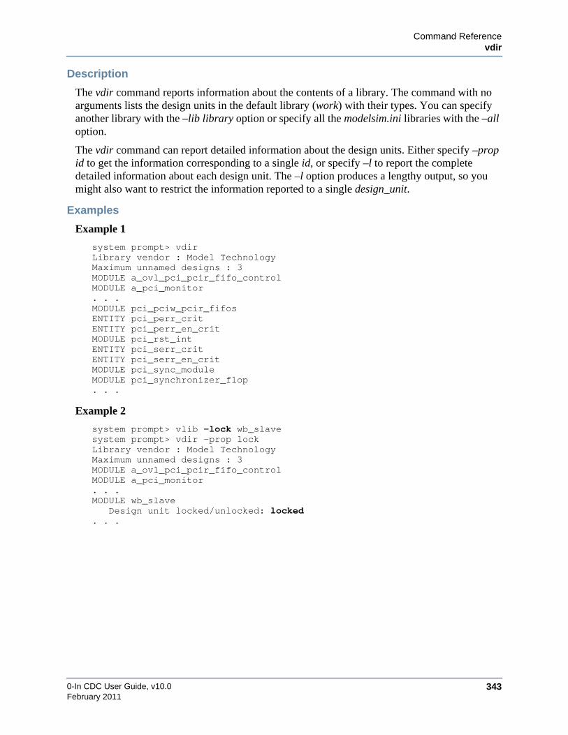
Command Referencevdir
0-In CDC User Guide, v10.0 343February 2011
Description
The vdir command reports information about the contents of a library. The command with noarguments lists the design units in the default library (work) with their types. You can specifyanother library with the –lib library option or specify all the modelsim.ini libraries with the –alloption.
The vdir command can report detailed information about the design units. Either specify –propid to get the information corresponding to a single id, or specify –l to report the completedetailed information about each design unit. The –l option produces a lengthy output, so youmight also want to restrict the information reported to a single design_unit.
Examples
Example 1
system prompt> vdirLibrary vendor : Model TechnologyMaximum unnamed designs : 3MODULE a_ovl_pci_pcir_fifo_controlMODULE a_pci_monitor. . .MODULE pci_pciw_pcir_fifosENTITY pci_perr_critENTITY pci_perr_en_critMODULE pci_rst_intENTITY pci_serr_critENTITY pci_serr_en_critMODULE pci_sync_moduleMODULE pci_synchronizer_flop. . .
Example 2
system prompt> vlib -lock wb_slavesystem prompt> vdir -prop lockLibrary vendor : Model TechnologyMaximum unnamed designs : 3MODULE a_ovl_pci_pcir_fifo_controlMODULE a_pci_monitor. . .MODULE wb_slave
Design unit locked/unlocked: locked. . .

0-In CDC User Guide, v10.0344
Command Referencevdir
February 2011
Example 3
system prompt> vdir -l synchronizer_flopLibrary vendor : Model TechnologyMaximum unnamed designs : 3MODULE synchronizer_flop Package reference number: 1 sv_std std Depends on: X sv_std std WnQ=;W1X^o9K1PIQTgInR3 Verilog version: 75H<P_OOUP;li]1h@XcB20 Version string: Vz3hiFlX4K>9PJJZjj9EW2 Source directory: /u/ramesh/examples/fv_demo/zin/demo Source modified time: Thu Oct 29 14:17:15 2009 HDL source file: ../../pci/rtl/verilog/synchronizer_flop.v Source file: ../../pci/rtl/verilog/synchronizer_flop.v Start location: ../../pci/rtl/verilog/synchronizer_flop.v:105 Opcode format: QA Baseline: 6.6 - 2149934; VLOG SE Object version 44 Optimized Verilog design root: 1 VHDL language standard: 1 Compile options: -sv -permissive -mixedansiports
-compile_uselibs=/u/ramesh/examples/fv_demo/zin/demo/log_static/0in_cache/AN/compile_uselibs_output -pslallowseverity-synthprefix {$s} -synthprefix {$s} -cuname root_cuname -mfcu+libext+.vlib -L mtiAvm -L mtiOvm -L mtiUPF

Command Referencevdel
0-In CDC User Guide, v10.0 345February 2011
vdelDeletes design units from a library.
Syntax
vdel{–all | primary [arch] | –allsystemc} [–lib library] [–modelsimini file] [–verbose]
• –all
Delete the entire library.
CautionYou are not prompted for confirmation. Once deleted, the library cannot be recovered.
• primary [arch]
Design unit to delete: primary is the entity, package, configuration, or module; arch is aspecific architecture for primary. If primary is an entity and arch is not specified, allarchitectures of primary are deleted. Not supported for SystemC modules.
• –allsystemc
Delete all SystemC modules.
• –lib library
Delete from library (logical or physical library). Default library: work.
• –modelsimini file
Use file as the modelsim.ini file to determine the library. Default: ./modelsim.ini.
• –verbose
Report progress messages.
Description
The vdel command deletes a design unit from a library, deletes all SystemC modules in alibrary, or deletes an entire library.
0-In CDC User Guide, v10.0346
Command Referencevdel
February 2011
Examples
Example 1
system prompt> vdel shiba -all
Deletes the shiba library.
Example 2
system prompt> vdel xor behavior
Deletes the behavior architecture of the xor entity from the work library.

Command Reference0in
0-In CDC User Guide, v10.0 347February 2011
0inRuns the 0in shell.
Syntax
0in [–version] [–l log_file] [–detail detailed_log_file] [–nl][–limit_messages][–cache dir] [–rel_paths] [–od output_dir] [–sim {questa | vcs | nc | nc3}][–licq] [script_file | –cmd command_string]
• –version
Print the version information and exit.
• –l log_file
Rename the generated 0in shell log file. Default: 0in.log.
• –detail detailed_log_file
Rename the generated detailed 0in shell log file. Default: 0in_detail.log.
• –nl
Disable message logging to the detailed log and the 0in shell log. Default: messages arelogged.
• –limit_messages
Limit the number of messages in the detailed log. For each message type encountered, onlythe first 10 messages are logged. Default: all messages are logged.
• –cache dir
Rename the generated 0in cache directory for the session. Default: 0in_cache in the outputdirectory.
• –rel_paths
Uses relative pathnames in generated argument files. Default: full paths.
• –od output_dir
Directory to store all output files. Default: current directory.
• –sim {questa | vcs | nc | nc3}
Target simulator: Questa, VCS, NC–Verilog, 3–step NC–Verilog. Default: questa (with thesame version as the vsim executable in the current search path).
• –licq
Enables license queuing for 0in shell commands. Default: command terminates if therequired license is being used. Use this option to enqueue multiple sessions that areexecuted automatically as licenses become available. To do this, include +0in_licq as a 0inshell command option. For example:
shell prompt> 0in +0in_licq -cmd csl ....
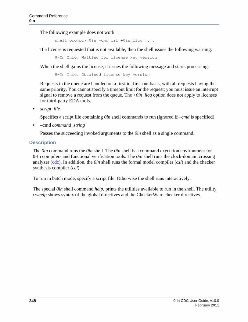
0-In CDC User Guide, v10.0348
Command Reference0in
February 2011
The following example does not work:
shell prompt> 0in -cmd csl +0in_licq ....
If a license is requested that is not available, then the shell issues the following warning:
0-In Info: Waiting for license key version
When the shell gains the license, it issues the following message and starts processing:
0-In Info: Obtained license key version
Requests in the queue are handled on a first-in, first-out basis, with all requests having thesame priority. You cannot specify a timeout limit for the request; you must issue an interruptsignal to remove a request from the queue. The +0in_licq option does not apply to licensesfor third-party EDA tools.
• script_file
Specifies a script file containing 0in shell commands to run (ignored if –cmd is specified).
• –cmd command_string
Passes the succeeding invoked arguments to the 0in shell as a single command.
Description
The 0in command runs the 0in shell. The 0in shell is a command execution environment for0-In compilers and functional verification tools. The 0in shell runs the clock-domain crossinganalyzer (cdc). In addition, the 0in shell runs the formal model compiler (csl) and the checkersynthesis compiler (ccl).
To run in batch mode, specify a script file. Otherwise the shell runs interactively.
The special 0in shell command help, prints the utilities available to run in the shell. The utilitycwhelp shows syntax of the global directives and the CheckerWare checker directives.

Command Reference0in_cdc
0-In CDC User Guide, v10.0 349February 2011
0in_cdcRuns the CDC GUI environment.
Syntax
0in_cdc[ [–db] db_file [–restore_state gui_state_file | {–mergedb db_file}…]| project_file [–restore_state gui_state_file]| [–p project_name ] [hdl_file]… [–d design] [–f verilog_filelist]… [–vhf vhdl_filelist]…
[[–ctrl verilog_control_file]… [–vhctrl vhdl_control_file]… | [–ctrl_module module]…][–import_ctrl control_file]… [–v95] [–libmapfile library_map_file]… [–y lib_dir]…[–v lib_file]… [–work library] [–od output_dir] [–no_directive_error_check][+libext{+ext}…]… [+incdir{+dir}…]… [+define{+macro[=val]}…]…[–sdc_in sdc_file] [–sdc_out file] [–formal] [–block module…] [–cdcid id] [–verbose]
]
• db_file
Formal database file (.db) to load.
• –mergedb db_file
Formal database file (.db) to merge (as with File >Merge Database).
• project_file
Project file (.zpf) to load.
• –p project_name
Project or project file (.zpf) to load. If a project with the name project_name does not exist,a new project with that name is created.
• –restore_state gui_state_file
Load the initial state of the GUI windows from gui_state_file. Use File >Export >State tosave the current GUI state to a file. This command also creates a run file having the samename, but with a _run extension. The run file runs the GUI with the .db file or project andthe -restore_state option. You can use this process to “freeze” the view of the GUI so youcan examine it later or from another system. Default: state of the GUI windows does notshow the debug tools opened when the project was saved.
• hdl_file
HDL files to add to the project.
• design
Name of the top-level DUT design unit.
• –f verilog_filelist
Text file listing Verilog source files. Maximum pathname length: 1024 characters.

0-In CDC User Guide, v10.0350
Command Reference0in_cdc
February 2011
• –vhf vhdl_filelist
Text file listing VHDL source files.
• –ctrl verilog_control_file
Verilog control file.
• –vhctrl vhdl_control_file
VHDL control file.
• –ctrl_module module
Module or design unit in the -work library to use as a 0-In control file. You can usevcom/vlog to compile a 0-In control file (for example, if a 0-In control module or 0-Incontrol design unit contains modeling logic), then use the -ctrl_module option to indicatethe 0-In control modules and control design units used for analysis.
• –import_ctrl control_file
Verilog or VHDL control file containing global directives to import so they can be edited inthe directive editor dialogs (as with File >Import >Directives).
• –v95
Assume Verilog 95 syntax. Default: Verilog 2K.
• –libmapfile library_map_file
Library mapping file.
• –y lib_dir
Directory containing library files.
• –v lib_file
Library file.
• –work work_dir
GUI work directory. Default: ./work.
• –od output_dir
Output directory for reports and databases.
• –no_directive_error_check
Turns off error checking (i.e., signals, ports, modules exist) in the directives dialogs.
• +libext{+ext}…
File extensions of library files to search for. Example: +libext+.v+.vhd
• +incdir{+dir}…
Directories containing the include files. Example: +libext+include+../common/include

Command Reference0in_cdc
0-In CDC User Guide, v10.0 351February 2011
• +define{+macro[=val]}…
Verilog macro defines. Example: +define+STATIC_FIFO+FIFO_SIZE=16
• –sdc_in sdc_file
Load the specified SDC file and use the SDC data to set up CDC analysis.
• –sdc_out file
Write the SDC data to file for use in downstream tools.
• –formal
Run formal CDC during static CDC analysis.
• –block module…
Treat the module/entities as blocks for hierarchical analysis.
• –cdcid id
CDC crossing to select and show the corresponding source code.
• –verbose
Turn on verbose reporting (see “cdc” on page 359).
Description
The 0in_cdc shell command runs the CDC GUI environment.
Examples
shell prompt> 0in_cdc
Runs the CDC GUI with no data loaded. The blank main window appears.
shell_prompt> 0in_cdc -p mem_ctrl -d top -od mem_ctrl_work \
-f ../source/filelist.mem_ctrl -ctrl bin/cdc_control.v \
-vhf mem_ctrl.vh -sdc_in mem_ctrl.sdc
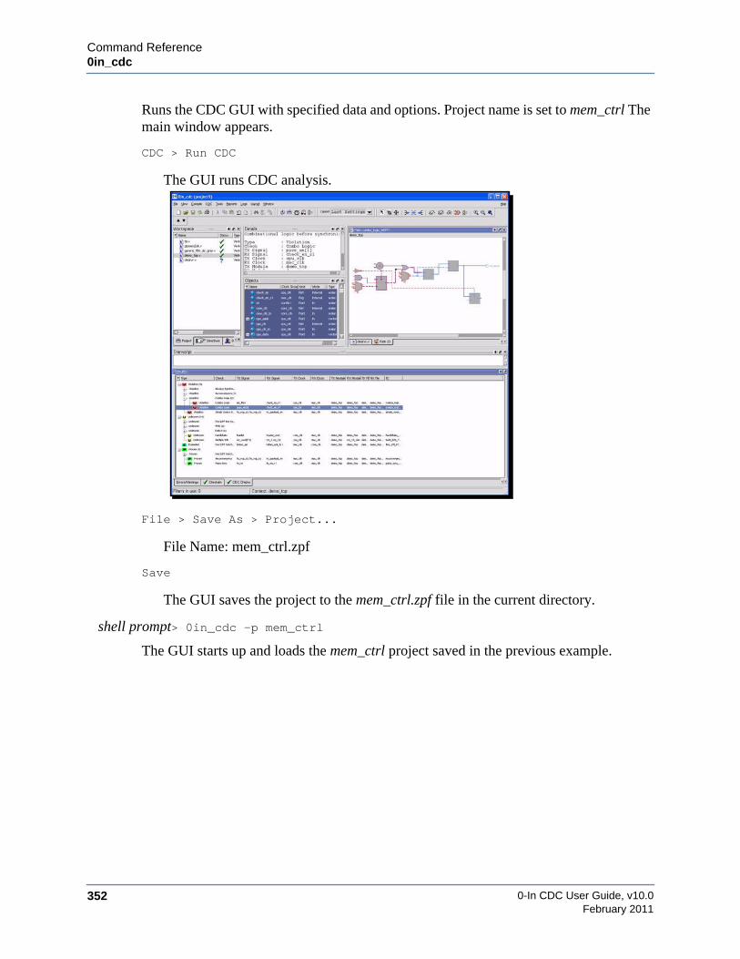
0-In CDC User Guide, v10.0352
Command Reference0in_cdc
February 2011
Runs the CDC GUI with specified data and options. Project name is set to mem_ctrl Themain window appears.
CDC > Run CDC
The GUI runs CDC analysis.
File > Save As > Project...
File Name: mem_ctrl.zpf
Save
The GUI saves the project to the mem_ctrl.zpf file in the current directory.
shell prompt> 0in_cdc -p mem_ctrl
The GUI starts up and loads the mem_ctrl project saved in the previous example.

Command Reference0in_db2ucdb
0-In CDC User Guide, v10.0 353February 2011
0in_db2ucdbTranslates a 0-In database (.db file) into a UCDB database; or creates a .do file that excludescertain AutoCheck violations from coverage metrics calculated by vsim/vcover; or creates areport file for a specified UCDB.
Syntax
0in_db2ucdb in_file out_file{–prefix hierarchy_prefix –prefix_modules “module…” [–cdc] | –exclude | –report}
• in_file
Source file for the operation. For UCDB generation and exclusion .do file generation, in_fileis a 0-In database file (.db). For report file generation, in_file is a UCDB file.
• out_file
Name to give the generated file.
• –prefix hierarchy_prefix
Location in the design library of the generated UCDB scheme.
• –prefix_modules “module…”
Design units to include in the translation.
• –cdc
Translate CDC data from the 0-In database file. Default: no CDC is translated.
• –exclude
Create a .do file of exclusion commands for input to vsim and do not generate a UCDB file.
• –report
Create a report file showing the information in the specified UCDB file.
Description
The 0in_db2ucdb command has three functions:
• Translate a 0-In DB file to a UCDB file. For example:
0in_db2ucdb 0in_confirm.db 0in.ucdb -prefix work.tb.dut \-prefix_modules “tb dut”
• Create an exclusion .do file from a 0-In DB file. For example:
0in_db2ucdb 0in_autocheck.db 0in.do
• Create a report from a UCDB file. For example:
0in_db2ucdb 0in.ucdb 0in.rpt -report

0-In CDC User Guide, v10.0354
Command Reference0in_db2ucdb
February 2011
0-In AutoCheck
0-In AutoCheck analysis detects three types of information relevant to UCDBs: unreachableFSM states, unreachable FSM transitions and unreachable blocks of code. After debugging anyissues found by autocheck analysis, any remaining unreachable FSM states/transitions andblocks of code are presumably OK. However, after running simulations and merging results,these unreachable objects are used in the calculations of FSM and line coverage reported byvcover. The effect is that reported coverage measures are lower than necessary.
To work around this problem, you can exclude certain coverage objects from the coveragecalculations using the coverage exclude commands. For example:
coverage exclude -du work.shiba.fsm_a -fstate state 4’b0111coverage exclude -du work.shiba.fsm_a -fstate state 4’b1000coverage exclude -du work.shiba.fsm_a -ftrans state {4’b0110 -> 4’b0111}coverage exclude -du work.shiba.fsm_a -fstate current_state 5’b01000coverage exclude -du work.shiba.fsm_a -fstate current_state 5’b10000coverage exclude -du work.shiba.t2 -srcfile dut.v -linerange 75coverage exclude -du work.shiba.t2 -srcfile dut.v -linerange 76
These commands exclude state states 4’b0111 and 4’b1000, state transition 4’b0110 ->4’b0111, current_state states 5’b01000 and 5’b10000, and lines 75-76 in dut.v from coveragecalculations. Since autocheck analysis has already detected these unreachable objects, you donot need to manually code these exclusions—they are automatically generated by 0in_db2ucdbwith the -exclude option:
prompt> 0in_autocheck ....prompt> 0in_db2ucdb -exclude 0in_autocheck.db exclude.do...prompt> vsim ... exclude.do...prompt> vcover report -select f -bydu sim.ucdb > du.reportprompt> vcover report code s sim.ucdb > cover.report
0-In CDC
The UCDB schema supports CDC attributes, however current vsim versions do not access anyof this information. You can access CDC information via the UCDB API (see UCDB APIReference), however, you must include the following header file in the API code:
$HOME_0in/share/inluce/ucdb_cdc.h
This header defines the CDC_RECORD key and the supporting attributes.
To include CDC data in the UCDB translation, specify the -cdc option to 0in_db2ucdb.
If you specify -cdc when translating a CDC db file to a ucdb file, then run 0in_db2ucdb -reporton the generated ucdb file, the utility creates a report with the CDC information included. Forexample:
prompt> 0in_db2ucdb -prefix tb.dut -prefix_modules “pci” \-cdc 0in_cdc.db 0in_cdc.ucdbprompt> 0in_db2ucdb -report 0in_cdc.ucdb cdc.reportprompt> more cdc.report
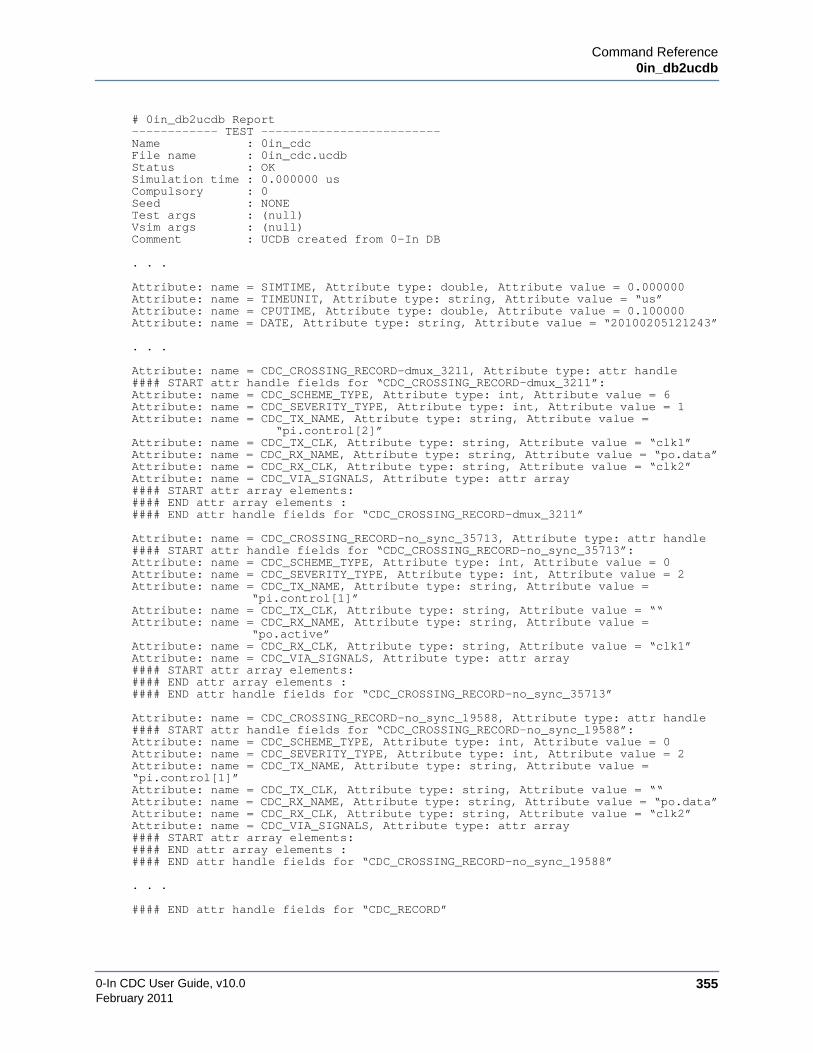
Command Reference0in_db2ucdb
0-In CDC User Guide, v10.0 355February 2011
# 0in_db2ucdb Report------------ TEST -------------------------Name : 0in_cdcFile name : 0in_cdc.ucdbStatus : OKSimulation time : 0.000000 usCompulsory : 0Seed : NONETest args : (null)Vsim args : (null)Comment : UCDB created from 0-In DB
. . .
Attribute: name = SIMTIME, Attribute type: double, Attribute value = 0.000000Attribute: name = TIMEUNIT, Attribute type: string, Attribute value = “us”Attribute: name = CPUTIME, Attribute type: double, Attribute value = 0.100000Attribute: name = DATE, Attribute type: string, Attribute value = “20100205121243”
. . .
Attribute: name = CDC_CROSSING_RECORD-dmux_3211, Attribute type: attr handle#### START attr handle fields for “CDC_CROSSING_RECORD-dmux_3211”:Attribute: name = CDC_SCHEME_TYPE, Attribute type: int, Attribute value = 6Attribute: name = CDC_SEVERITY_TYPE, Attribute type: int, Attribute value = 1Attribute: name = CDC_TX_NAME, Attribute type: string, Attribute value =
“pi.control[2]”Attribute: name = CDC_TX_CLK, Attribute type: string, Attribute value = “clk1”Attribute: name = CDC_RX_NAME, Attribute type: string, Attribute value = “po.data”Attribute: name = CDC_RX_CLK, Attribute type: string, Attribute value = “clk2”Attribute: name = CDC_VIA_SIGNALS, Attribute type: attr array#### START attr array elements:#### END attr array elements :#### END attr handle fields for “CDC_CROSSING_RECORD-dmux_3211”
Attribute: name = CDC_CROSSING_RECORD-no_sync_35713, Attribute type: attr handle#### START attr handle fields for “CDC_CROSSING_RECORD-no_sync_35713”:Attribute: name = CDC_SCHEME_TYPE, Attribute type: int, Attribute value = 0Attribute: name = CDC_SEVERITY_TYPE, Attribute type: int, Attribute value = 2Attribute: name = CDC_TX_NAME, Attribute type: string, Attribute value =
“pi.control[1]”Attribute: name = CDC_TX_CLK, Attribute type: string, Attribute value = ““Attribute: name = CDC_RX_NAME, Attribute type: string, Attribute value =
“po.active”Attribute: name = CDC_RX_CLK, Attribute type: string, Attribute value = “clk1”Attribute: name = CDC_VIA_SIGNALS, Attribute type: attr array#### START attr array elements:#### END attr array elements :#### END attr handle fields for “CDC_CROSSING_RECORD-no_sync_35713”
Attribute: name = CDC_CROSSING_RECORD-no_sync_19588, Attribute type: attr handle#### START attr handle fields for “CDC_CROSSING_RECORD-no_sync_19588”:Attribute: name = CDC_SCHEME_TYPE, Attribute type: int, Attribute value = 0Attribute: name = CDC_SEVERITY_TYPE, Attribute type: int, Attribute value = 2Attribute: name = CDC_TX_NAME, Attribute type: string, Attribute value =“pi.control[1]”Attribute: name = CDC_TX_CLK, Attribute type: string, Attribute value = ““Attribute: name = CDC_RX_NAME, Attribute type: string, Attribute value = “po.data”Attribute: name = CDC_RX_CLK, Attribute type: string, Attribute value = “clk2”Attribute: name = CDC_VIA_SIGNALS, Attribute type: attr array#### START attr array elements:#### END attr array elements :#### END attr handle fields for “CDC_CROSSING_RECORD-no_sync_19588”
. . .
#### END attr handle fields for “CDC_RECORD”

0-In CDC User Guide, v10.0356
Command Reference0in_db2ucdb
February 2011
------------- DESIGN UNIT ------------------Name : work.tb_topType : UCDB_DU_MODULESource type : VERILOGFile info : name = unknown.v line = 2Flags : 0x00000100Attribute: name = #DUSIGNATURE#, Attribute type: string, Attribute value =“(null)”
------------- DESIGN UNIT ------------------Name : work.topType : UCDB_DU_MODULESource type : VERILOGFile info : name = /u/cshaw/examples/ucdb_cdc/cdc.sv line = 15Flags : 0x00000100Attribute: name = #DUSIGNATURE#, Attribute type: string, Attribute value =“(null)”
------------- INSTANCE SCOPE ----------------Name : .tb_topType : UCDB_INSTANCESource type : VERILOGFile info : name = <none> line = 2DU Scope : work.tb_topWeight : 1Flags : 0x00000000
------------- INSTANCE SCOPE ----------------Name : .tb_top.top0Type : UCDB_INSTANCESource type : VERILOGFile info : name = <none> line = 15DU Scope : work.topWeight : 1Flags : 0x00000000
0-In Formal
0-In Formal analysis detects three types of information relevant to UCDBs and assertioncoverage:
• An assertion firing increments the assertion’s failure count.
• An assertion’s sanity check firing increments the assertion’s pass count
• A cover point’s covered count is added to the cover point’s coverage count.
Use 0in_db2ucdb to generate a UCDB file that you can merge with simulation UCDBs toupdate your coverage reports with this information. For example, assume vsim simulationgenerated a UCDB file called vsim.ucdb and the Assertions window looks like:
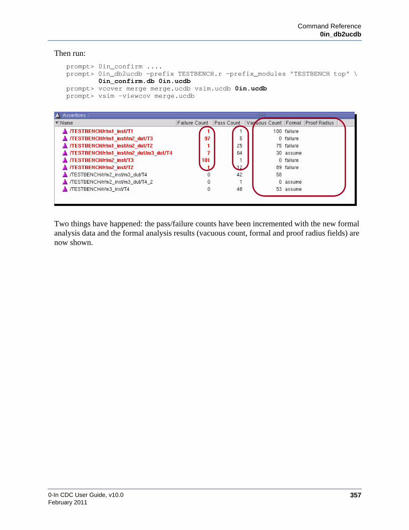
Command Reference0in_db2ucdb
0-In CDC User Guide, v10.0 357February 2011
Then run:
prompt> 0in_confirm ....prompt> 0in_db2ucdb -prefix TESTBENCH.r -prefix_modules "TESTBENCH top" \
0in_confirm.db 0in.ucdbprompt> vcover merge merge.ucdb vsim.ucdb 0in.ucdbprompt> vsim -viewcov merge.ucdb
Two things have happened: the pass/failure counts have been incremented with the new formalanalysis data and the formal analysis results (vacuous count, formal and proof radius fields) arenow shown.
0-In CDC User Guide, v10.0358
Command Reference0in Shell Commands
February 2011
0in Shell CommandsThe 0in shell commands are the formal verification utilities executed from within the 0in shell(see “0in” on page 347). These commands typically are run in batch mode from a commandstring or batch script. The 0in command can also be run interactively and each of the 0in shellutilities can be invoked from the 0in shell session.
The 0in shell commands include the assertions compiler for simulation (ccl) and the formalmodel compiler (csl) for formal verification. For CDC analysis, the 0in shell has the followingutility:
• cdc — CDC compiler.
The 0in shell also has a command-line help facility, which has the following invocations:
• shell prompt>0in -help
Reports the syntax for the 0in command.
• 0in>command -help
Reports the syntax for the command 0in shell command. For example:
0in>cdc -help
• 0in>cwhelp [global_directive | checker_type]
Reports the syntax for the specified global directive or checker type (see “cwhelp” onpage 373). For example:
0in>cwhelp set_cdc_report
0in>cwhelp bits_on
NoteYou cannot include UNIX environment variables in a 0in shell script or within aninteractive 0in shell session. However, it is permitted to include UNIX environmentvariables when invoking from the system shell prompt or from a system shell script.

Command Referencecdc
0-In CDC User Guide, v10.0 359February 2011
cdcCompiles a clock domain model of the design; performs static CDC analysis; promotes CDCprotocol assertions for formal verification and simulation; and promotes CDC-FX metastabilityinjection logic for simulation.
Syntax
cdc –d design[ –report_clock | –report_modes| –report_hier_scripts | –report_constraints block_pattern…| –hier | –hier_block block [-output_hier_ctrl file] | –hier_instance instance…| [–hier_cache ILM_cache…] [–hier_ctrl_file_model block CFM_ctrl_file]…][–work work_library] [–modelsimini init_file] [{–L | –Lf} library]…[–cuname comp_unit]… [–cache pathname]
control_options := [[–ctrl control_file]… [–ctrl_list control_filelist…] [–v95 | –v2k | –sv][–vhctrl control_file]… [–93 | –87 | –2002 | –2008] | [–ctrl_module module]… ]
reporting_options := [–cr report_file] [–verbose] [–gen_port_domain_template][–print_all_cdc_paths] [+nowarn{+messageID}…] [+error{+messageID}…]
sdc_options := [–sdc_in sdc_file] [–sdc_out file] [–report_sdc]
advanced_options := [–de {[module.]inst_pattern}…] [–di {[module.]inst_pattern}…][–G name=value]… [–g name=value]… [–mode mode] [–fx] [–process_dead_end][–effort unlimited] [–formal [–formal_effort {low | medium | high | maximum}]][–auto_blackbox]
compile_cdc_assertions_options := [–compile_assertions –prefix hierarchy_prefix[–compiled_assertion_report file] [–sim {questa | vcs | nc | nc3}][–sif root_name] [–rel_paths] ]
• –d design
HDL design unit to be verified. To specify a particular VHDL architecture for a top-levelentity, specify the architecture in parentheses with the entity name. For example: –d“top(arch)”.
• –report_clock
Report only clock domains and exit. Default: perform full CDC analysis.
• –report_modes
Generate a mode report in the 0in_detail.log file and exit. Default: run CDC analysis; do notgenerate a mode report.
• –report_hier_scripts
Generate hierarchical flow scripts; and exit. The generated flow scripts create their outputfiles in the directory specified by the -od 0in shell option (default: run directory).

0-In CDC User Guide, v10.0360
Command Referencecdc
February 2011
• –report_constraints block_pattern…
Generate hierarchical constraints files for the matching blocks (modules and entities);generate hierarchical flow scripts; and exit. The generated flow scripts create their outputfiles in the directory specified by the -od 0in shell option (default: run directory).
• –hier
Generate an interface logic model of the CDC logic of the design using a user-specifiedCDC constraints file (i.e., one manually constructed). This model is used to run hierarchicalCDC analysis when the current DUT is instantiated as part of a larger design. Use thisoption if the top-level design is not available.
• –hier_block block
Run block-level hierarchical CDC analysis for block (Verilog module or VHDL design unit)using the hierarchical CDC constraints in the specified control file (created by a previouscdc session using -report_constraints). Using the results, generate a CDC interface logicmodel for the block for use in top-level CDC analysis. Use this option if all instances of theblock are homogeneous.
• –output_hier_ctrl file
Name to give the control file generated for the block (when set_cdc_hier_preference-ctrl_file_models is specified). Default: 0in_cdc_hier_<block>_ctrl.v.
• –hier_instance instance…
Run block-level hierarchical CDC analysis for the specified homogeneous instances of ablock using the hierarchical CDC constraints in the specified control file (created by aprevious cdc session using -report_constraints). Using the results, generate a CDC interfacelogic model for the group of instances for use in top-level CDC analysis. Use this option ifthe instances of the block are not homogeneous.
• –hier_cache ILM_cache…
Use the specified CDC interface logic model caches generated from block-level analysesand perform top-level hierarchical CDC analysis on the DUT.
• –hier_ctrl_file_model block CFM_ctrl_file
Use the CDC control file model corresponding to block in CFM_ctrl_file (which is typicallygenerated by block-level analysis of block) and perform top-level hierarchical CDC analysison the DUT.
• –work work_library
Logical name of the design library containing precompiled design units. Also used as thetarget library for compilation performed by cdc. If work_library does not exist, it is created.Default: work in the current run directory.
• –modelsimini init_file
Load init_file as the compiler initialization (modelsim.ini) file, which is used when vopt iscalled (under the hood). If you ran vlog and vcom compilation with the -modelsimini

Command Referencecdc
0-In CDC User Guide, v10.0 361February 2011
init_file option, you must use this option with cdc and the option must point to the same file.Default: search path shown in Figure 3-4 on page 59.
• –L library | –Lf library
Resource library containing pre-compiled modules for the clock domain model compilation.With the –Lf argument, library is searched before searching in the effective ‘uselib library(if specified) for the instantiation. With the –L argument, library is searched after searchingthe effective ‘uselib library. The LibrarySearchPath variable defines an initial resourcelibrary search path. When searching for a module for an instantiation, the libraries specifiedby LibrarySearchPath are searched in (left-to-right) order, as if they were specified with the–L argument. If no match is found, the libraries specified in the –Lf and –L options aresearched in the order specified in the command invocation.
• –cuname comp_unit
Specifies -cuname comp_unit when vopt is called (under the hood). If you ran vlogcompilation with the -cuname comp_unit option, you must use the same option with csl/cdc.This option can be specified multiple times. Note that for 1-step csl/cdc compilation,-cuname root_cuname (default name of the global SystemVerilog package) is passedautomatically. The root_cuname package contains everything outside the compiledmodules/packages. When preparing to run Questa simulation, include the -cunameroot_cuname option to vlog and vcom to catch these extra constructs.
• –cache pathname
0in cache directory. Default: same as the 0in shell cache directory.
Control Options
• –ctrl control_file
Verilog-flavor control file.
• –ctrl_list control_filelist… [–]
Verilog-flavor control file list. The dash (–) terminate a list of file names to separate thenames from Verilog file names.
• –v95 | –v2k | –sv
Verilog version (Verilog-95, Verilog 2000 or SystemVerilog) used in Verilog-flavor controlfiles. Default: –v2k if modelsim.ini variable vlog95compat is 0 or –95 if vlog95compat is 1.In Verilog 1-step mode, this argument specifies the Verilog version (–v95 or –v2k) used bythe design files having .v extensions. Files with .sv extensions are assumed to beSystemVerilog files. Default for Verilog 1-step: -v2k.
• –vhctrl control_file
VHDL-flavor control file.

0-In CDC User Guide, v10.0362
Command Referencecdc
February 2011
• -87 | -93 | -2002 | -2008
VHDL version: VHDL-87, VHDL-93, VHDL-2002 or VHDL-2008 used in VHDL-flavorcontrol files. Default: value specified by the VHDL93 variable (default 2002) inmodelsim.ini.
• –ctrl_module module
Module or design unit in the -work library to use as a 0-In control file. You can usevcom/vlog to compile a 0-In control file (for example, if a 0-In control module or 0-Incontrol design unit contains modeling logic), then use the -ctrl_module option to indicatethe 0-In control modules and control design units used for analysis.
For example, if ctrl.v is a 0-In control file with a Verilog module ctrl_mod that containsglobal directives. then the following sequence of commands:
prompt> vlog ctrl.vprompt> 0in -cmd cdc -d dut -ctrl_module ctrl_mod
is equivalent to:
prompt> 0in -cmd cdc -d dut -ctrl ctrl.v
Reporting Options
• –cr report_file
Name to give the CDC report file. Default: 0in_cdc.rpt.
• –verbose
Report the filtered CDC crossings (turned off using the -severity off option of theset_cdc_report directives) and the stable signals (identified by set_cdc_signal directiveswith the -stable option) in the Filtered CDC Checks Summary section of the 0in_cdc.rptfile. Report detailed warning messages related to the set_cdc_report global directives. Forexample, by default, if a set_cdc_report global directive has an invalid wildcard signal or anincomplete list of signals for reconvergence filtering, then a warning message that the globaldirective did not match any CDC crossing is issued (directive-214). With -verbose, thewarning message specifies the type of error in the global directive. Also report the list ofsignals that match wildcard patterns for each directive that supports wildcards in arguments.
To report crossings filtered by set_cdc_report -severity off and set_cdc_signal -stabledirectives—but not the other extra information—use set_cdc_preference -filtered_reportdirectives.
• –gen_port_domain_template
Generate a 0in_cdc_port_domain_template.v file containing set_cdc_port_domaindirectives for the primary ports.
• –print_all_cdc_paths
Print all CDC paths to 0in_cdc_path.rpt.

Command Referencecdc
0-In CDC User Guide, v10.0 363February 2011
• +nowarn{+messageID}…
Turn off reporting of the specified warning messages. Message ID is a category and number(e.g., parser-47). Default: all warning messages reported.
• +error{+messageID}…
Turn the specified warning messages into errors. Message ID is a category and number(e.g., parser-47).
SDC Options
• –sdc_in sdc_file
Load the specified SDC file and use the SDC data to set up CDC analysis.
• –sdc_out file
Write the SDC data to file for use in downstream tools.
• –report_sdc
Generate the 0in_sdc_ctrl.v control file with global directives for the SDC data.
Advanced Options
• –de {[module.]inst_pattern}…
Exclude instances in module that match inst_pattern. Default module is the design.
• –di {[module.]inst_pattern}…
Exclude instances in module that do not match inst_pattern. Default module is the design.The following example shows usage of –di and –de together.
• –G name=value
Override the final value of the generic/parameter specified by name. The name can be ahierarchical path. For example, irrespective of the value in the source code, the value usedfor dut.u1.p1 is 10 in the following invocation.
0in -cmd cdc -d dut -G dut.u1.p1=10 -G p2=20 -infer_clk
0-In and Questa implementations for -G differ slightly:
i1 i2
i3 e1
mid
topm2
m1 top
m1
m2
i1 i2
i3 e1
i1 i2
i3 e1
-di m1-de mid.i*
excluded logic
0-In CDC User Guide, v10.0364
Command Referencecdc
February 2011
• Command Line — 0-In has no blank space between the -G option and the parameter.For example: -G p1=10 (0-In) vs -Gp1=10 (Questa).
• –g name=value
Default value of the generic/parameter specified by name. The name can be a hierarchicalpath. For example, unless the value of p1 is set by a defparam statement, the value used forp1 is 10 in the following invocation.
0in -cmd cdc -d top -g p1=10 -g p2=20 -infer_clk
0-In and Questa implementations for -g differ slightly:
• Command Line — 0-In has no blank space between the -g option and the parameter.For example: -g p1=10 (0-In) vs -gp1=10 (Questa).
• –mode mode
Infer all modes of operation or run CDC modal analysis on the design using the specifiedmode and exits (without doing any CDC analysis). Generate a modal script (0in_mode.scr).Directives that specify -mode arguments with different modes are ignored. Default: runregular CDC analysis. Directives that specify any -mode arguments are ignored.
• –fx
Generate the 0in_cdc_fx_sim_ctrl.v control file with directives for the promoted cdc_fxcheckers.
• –process_dead_end
Report all CDC issues, including paths that do not connect to output ports (dead end paths).Default: CDC does not report issues found on registers in dead logic.
• –effort unlimited
Set the effort level of CDC analysis to unlimited, which can increase runtime and memoryusage.
• –formal
Run formal CDC during static CDC analysis.
• –formal_effort {low | medium | high | maximum}
Effort level for CDC formal analysis. Default: low.
• -auto_blackbox
Turns all unresolved modules/entities into inferred black boxes. An unresolvedmodule/entity is one for which no module or entity/architecture definition is present. If acomponent declaration is present, the port directions are derived from that declaration.Otherwise, the port directions are inferred from the connected logic. If a port directioncannot be inferred, the port direction is assumed to be INOUT. Default: unresolved modulesare treated as unused/undriven logic.

Command Referencecdc
0-In CDC User Guide, v10.0 365February 2011
Compile CDC Assertions Options
• –compile_assertions
Compile CDC protocol checkers and CDC-FX checkers into the -work library and create asimulator arguments file for simulation. Use set_cdc_report -promotion off directives toskip compilation of CDC protocol checkers for specific crossings. Assertion compilationuses the CDC logic model to generate the CDC protocol assertions and CDC-FX logic usedby vsim. So compilation is much more efficient than running a separate ccl session tocompile the CDC assertion logic. Default: compilation for simulation is not performed.
• –prefix hierarchy_prefix
Hierarchy prefix showing the hierarchy from the top level (typically the testbench) to theDUT.
• –compiled_assertion_report file
Name to give the generated CDC assertion compilation report. Default:0in_cdc_checker.rpt.
• –sim {questa | vcs | nc | nc3}
Target simulators (VCS, NC-Verilog, or 3-step NC-Verilog). Default: same as the 0in shell.The default Questa version is the same as the vsim executable in the current search path.
• –sif file
Root name to give the generated simulation arguments file. Default root file name:0in_cdc_sim.arg.
• –rel_paths
Use relative pathnames in generated argument files. This option can be used to change the0in_check.db link path to not use the absolute path name. For example,
0in_check.db -> ./0in_cache/DB/0in_check.db
Default: same as the 0in shell.
Description
The 0-In CDC analyzer (cdc) performs static CDC analysis of a compiled design.The cdcanalyzer assumes all design units have been compiled into -work and if not, generates errormessages and exits.
Use the -report_clock option to report initial CDC information without performing a completeCDC analysis. Then use this information to set up the initial environment for performing CDCanalysis. After setting up the starting configuration, run cdc to perform a full CDC analysis(Figure 6-3).

0-In CDC User Guide, v10.0366
Command Referencecdc
February 2011
Figure 6-3. CDC Analysis with cdc
Compile CDC Assertions
If you specify –compile_assertions, cdc performs CDC analysis as usual, but also compilesassertion logic—and CDC-FX injectors, if you also specify -fx (Figure 6-4). The-compile_assertions argument also creates simulator arguments files used to direct vcom/vlogcompilation and vsim simulation. When specifying -compile_assertions, also include the -prefixhierarchy_prefix that identifies the hierarchy path from the testbench top level to the DUTanalyzed by cdc.
Figure 6-4. Compiling CDC Assertions
The following example has a Verilog testbench and a VHDL DUT:
1. Set up the work library.
prompt> vlib workprompt> vmap work work
cdc0in_cdc0in_cdc.db
controlfiles
vcom/vlogdesign
files
GUI
debuggingenvironment
-work library
vcom/vlog
vcom/vlog
vsim
cdc
0in_cdc
controlfiles
vcom/vlogdesign
files
GUI
debuggingenvironment
-work library-compile_assertions
-f 0in_cdc_sim.arg-f 0in_cdc_sim_vhdl.arg
testbenchfiles
0in_checksim.db
0in_cdc.db
merge

Command Referencecdc
0-In CDC User Guide, v10.0 367February 2011
2. Compile the design.
prompt> vcom dut.v
3. Run CDC analysis.
prompt> 0in -cmd cdc -d dut -ctrl dut_ctrl.v \-compile_assertions -prefix tb.dut_inst
4. Compile the protocol assertions with the simulation arguments files generated by cdc.
prompt> vlog -f 0in_cdc_sim.argprompt> vcom -f 0in_cdc_sim_vhdl.arg
5. Compile the testbench.
prompt> vlog tb.v
6. Run simulation. Specify the PLI library path for the simulator and the vsim argumentsfiles.
prompt> vsim -c tb -pli $HOME_0IN/lib/lib0InLoadMTIPLI.so \-f 0in_cdc_sim.arg.vsim -f 0in_cdc_sim.arg.vsimrun \-do "add log -r /*; run 1000; quit -f"
7. View the results in the GUI.
prompt> 0in_cdc 0in_cdc.db -mergedb 0in_checksim.db
The 0in_cdc.db database is generated by cdc; 0in_checksim.db is generated by vsim.
NoteThe -compile_assertions option currently compiles checkers for all enabled protocolchecks and CDC-FX checks. You can use set_cdc_report -promotion off directives tomark instances of CDC schemes that should not be promoted (so they are not compiledby -compile_assertions).
NoteRunning the cdc -report_constraints step of hierarchical CDC creates hierarchicalconstraints files for specified blocks. These files contain set_cdc_port_domain directivesfor the blocks’ ports. If a port is driven by multiple clock domains, is unused or isundriven, cdc cannot infer its clock domain and cannot create a set_cdc_port_domaindirective that properly handles the port. To “document” which block ports have theseproperties, cdc creates set_cdc_port_domain directives with -none arguments. Thesedirectives are skipped and do not constrain the blocks.

0-In CDC User Guide, v10.0368
Command Referencecdc
February 2011
Input Files
The input files for the cdc command are shown in Table 6-4.
Table 6-4. cdc Input Files
Output Files
The 0in_cache directory contains cached data for CDC analysis. Other output files are listed inTable 6-5.
Table 6-5. cdc Output Files
design library Specified with -work library.
control files Control files that contain global directives for the following operations:• Specifying attributes of clocks and clock groups.• Changing attributes of CDC schemes.• Setting preferences for CDC analysis.• Adjusting attributes of promoted CDC protocol assertions and
CDC-FX checkers.• Controlling netlist generation.
SDC files Optional SDC files to load and use to configure CDC analysis.
Hierarchical CDC Files used in hierarchical CDC flows:0in_cdc_hier_constraints_block_ctrl.v
Constraints file for running block-level CDC analysis on thespecified block. Generated by running -report_constraints at thetop level.
0in_hier/block/0in_cacheHierarchical CDC cache containing the ILM model of block,generated during block-level CDC analysis of block.
0in_cdc_hier_block_ctrl.vHierarchical CDC control file containing the CFM model ofblock, generated during block-level CDC analysis of block (ifset_cdc_hier_preference -ctrl_file_models is specified).
0in_cdc.db Database file of the cdc session.
0in.log Short log file for the session. This is a copy of thestandard output.
0in_detail.log Detailed log file for the session.
0in_cdc.rpt Clock domain crossing report. The -cr option renamesthis file.
0in_cdc_design.rpt CDC design report.
0in_design.rpt Design report.
0in_cdc_setting.rpt CDC settings report.
0in_cdc_path.rpt Details of the CDC paths. Generated if the cdc-print_all_cdc_paths option is specified.

Command Referencecdc
0-In CDC User Guide, v10.0 369February 2011
Examples
Example 1
system prompt> vlib worksystem prompt> vlog -f source/filelistQuestaSim-64 vlog 6.6c Compiler-- Compiling module tb-- Compiling module dpmem2clk. . .system prompt> 0in -cmd cdc -d demo_top0-In: 0-In Functional Verification System V3.0.... . .Command: cdcCommand arguments: -d demo_top. . .Top level modules:
0in_cdc_mode_ctrl.v Control file containing directives that specify the modeinferred by modal analysis. Generated if the cdc-report_modes option is specified.
0in_cdc_param.inc Include file referenced by 0in_cdc_ctrl.v.
SDC output file File name is specified by -sdc_out. Default:0in_sdc_ctrl.v.
Hierarchical CDC Files used in hierarchical CDC flows:0in_cdc_hier_constraints_block_ctrl.v
Generated by running -report_constraints at thetop level.
0in_hier/block/0in_cacheGenerated during block-level CDC analysis ofblock.
0in_cdc_hier_block_ctrl.vGenerated during block-level CDC analysis ofblock (if set_cdc_hier_preference-ctrl_file_models is specified).
Compile Assertions Files generated by -compile_assertions:0in_cdc_sim.arg, 0in_cdc_sim_vhdl.arg,0in_cdc_sim.arg.vsim , 0in_cdc_sim.arg.vsimrun.These are generated for Questa use. If anothersimulator is specified, other files are generated as well.Also generated: a compile assertions report (defaultname: 0in_cdc_checker.rpt).
0in_cdc_port_domain_template.v Template file of the set_cdc_port_domain directives forthe primary ports (when -gen_port_domain_template isspecified).
0in_cdc_fx_sim_ctrl.v Control file containing CDC-FX checker directives forsimulation with metastability injection logic (when -fxis specified).

0-In CDC User Guide, v10.0370
Command Referencecdc
February 2011
demo_topAnalyzing design...-- Loading module demo_top-- Loading module generic_fifo_dc_gray-- Loading module dpmem2clk-- Loading module crc_16_calcOptimizing 4 design-units (inlining 0 instances):-- Optimizing module dpmem2clk(fast)Error: Design unit dump is compiled with older Questa simulator version.. . .Error : Design elaboration failed. [command-188] : Processing will abort.Error : Design Elaboration (Child process) returned a non zero status.
[command-195] : Processing will abort.
Error/Warning Summary-----------------------------------------------------------Count Type Message ID Summary----------------------------------------------------------- 1 Error command-188 Design elaboration failed.
1 Error command-195 Design Elaboration (Child process) returned anon zero status.
1 Error elaboration-113 Design unit dump is compiled with olderQuesta simulator version.
This example compiles the Verilog files using vlog and then runs the cdc command. An error isreturned because the design is compiled with an older version of vlog than the versioncompatible with V3.x tools. To avoid these types of errors, use the front-end utilities from the0-In installation software—not the utilities in the Questa installation.
Example 2
system prompt> $HOME_0IN/modeltech/bin/vlib worksystem prompt> $HOME_0IN/modeltech/bin/vlog -f source/filelistModel Technology ModelSim SE vlog QA Baseline: 6.6 ...-- Compiling module tb-- Compiling module dpmem2clk. . .system prompt> 0in -cmd cdc -d demo_top0-In: 0-In Functional Verification System V3.0. . .Command: cdcCommand arguments: -d demo_top. . .Parsing files...Analyzing designs.Processing CDC checks for module ’demo_top’Processing 113 candidatesProcessing 27 CDC signals after duplicate removal.
CDC Summary=================================================================Violations (8)-----------------------------------------------------------------Single-bit signal does not have proper synchronizer. (3)

Command Referencecdc
0-In CDC User Guide, v10.0 371February 2011
Combinational logic before synchronizer. (2)Reconvergence of synchronizers. (3)
Cautions (10)-----------------------------------------------------------------DMUX synchronization. (2)Multiple-bit signal synchronized by DFF synchronizer. (4)Multiple-bit signal across clock domain boundary. (1)Memory Synchronization. (2)Simple DMUX synchronization. (1)
Evaluations (8)-----------------------------------------------------------------Single-bit signal synchronized by DFF synchronizer. (7)Pulse Synchronization. (1)
Waived (0)-----------------------------------------------------------------<None>
Proven (0)-----------------------------------------------------------------<None>
Filtered (0)-----------------------------------------------------------------<None>. . .Error/Warning Summary-----------------------------------------------------------Count Type Message ID Summary-----------------------------------------------------------
1 Warning hdl-222 Possible dead end CDC paths not reported. 4 Warning hdl-41 Primary port connects to multiple clock domains. 25 Warning hdl-51 Port domain assignment inferred.
This example specifies the absolute path to the 0-In installed front-end utilities, whicheliminates the version mismatch error that occurs in Example 1.
Example 3: Compile Assertions (VCS)
This example runs cdc with the -compile_assertions option and runs CDC protocol simulationwith a VCS simulator.
vlib workvmap work workvlog test.v0in -sim vcs -cmd cdc -d test -compile_assertions -prefix tb.dutvcs -R test.v $HOME_0IN/0InPLI/vcs/lib0InvcsPLI.so -f 0in_cdc_sim.arg0in_cdc 0in_cdc.db -mergedb 0in_checksim.db
Example 4: Compile Assertions (NC)
This example runs cdc with the -compile_assertions option and runs CDC protocol simulationwith an NC-Verilog simulator.
vlib workvmap work work

0-In CDC User Guide, v10.0372
Command Referencecdc
February 2011
vlog test.v0in -sim nc -cmd cdc -d test -compile_assertions -prefix tb.dutncverilog test.v -f 0in_cdc_sim.arg0in_cdc 0in_cdc.db -mergedb 0in_checksim.db
Example 5: Compile Assertions (NC3)
This example runs cdc with the -compile_assertions option and runs CDC protocol simulationwith a 3-step NC simulator.
vlib workvmap work workvlog test.v0in -sim nc3 -cmd cdc -d test -compile_assertions -prefix tb.dutncvlog test.v -f 0in_cdc_sim.argncelab tb -snapshot test -f 0in_cdc_sim.arg.ncelabncsim test -f 0in_cdc_sim.arg.ncsim0in_cdc 0in_cdc.db -mergedb 0in_checksim.db

Command Referencecwhelp
0-In CDC User Guide, v10.0 373February 2011
cwhelpReports the syntax for a 0in global directive.
Syntax
cwhelp [directive]
• directive
Report syntax for directive. Default: list the global directives with short descriptions.
Description
The cwhelp 0in shell utility reports the directive syntaxes for the 0in global directives.
Examples
Default
The cwhelp utility with no arguments lists the global directives by the 0in utilities.
0in> cwhelp
Global Directive Syntax
After using cwhelp with no arguments to find the name of a global directive, use cwhelp againto find the syntax for the global directive:
0in> cwhelp default_resetCommand: cwhelpCommand arguments: default_reset
usage: default_reset
globalschecker_firing_keywordchecklist_off
checklist_on
default_reset. . .
Global DirectivesAdds a keyword to firing messagesExcludes a specified checklist checkfrom design fileIncludes a specified checklist checkfrom control fileSpecifies a default reset. . .
checkersalways
arbiter
arithmetic_overflow
. . .
Checker DirectivesEnsures that a specified signal alwaysasserts.
Ensures that an arbiter conforms to aspecified arbitration scheme and that nomore than one grant asserts at any time.
Ensures that in an assignment statement,the result of an arithmetic expressiondoes not overflow the left-hand-sidevariable.. . .

0-In CDC User Guide, v10.0374
Command Referencecwhelp
February 2011
[<signal>] [-module <module_name>] [-none] [-infer] [-posedge or -active_high or -negedge or -active_low] [-sync or -async] [-help]Specifies a default reset
The syntax shows alias names for arguments (for example, -posedge is an alias for-active_high).
Command ReferenceProtocol/FX Checkers
0-In CDC User Guide, v10.0 375February 2011
Protocol/FX CheckersEach checker type has a data sheet that provides the specification for checkers of that type. Datasheets contain the following information:
• Symbolic Representation
Symbolic representation of a generic checker of that type.
• Description
Description of the properties checked by checkers of the checker type.
• Syntax
Syntax statement for the checker directive.
• Corner Cases
Names of the corner case counts maintained by the checker.
• Statistics
Names of statistics maintained by these checkers, with explanations of each. Onestatistic is designated as the evaluation statistic (evals), which typically corresponds tothe number of times the checker evaluated.
• Notes
Notes describing any special features or requirements of these checkers.
• Examples
Examples of directives and checker applications.
Standard OptionsOne group of options (Table 6-6) is included in every syntax statement (except for certainspecial checker types that do not support some of the options). These options are calledstandard options and are indicated in syntax statements as:
[standard_option…]
These options are universal—they have the same meaning for each checker type.

0-In CDC User Guide, v10.0376
Command ReferenceProtocol/FX Checkers
February 2011
Table 6-6. Standard Options of a Checker Directive
standard_options ::=[-active signal] [-module mod] [-name identifier] [-group identifier] [-message “string”][-severity level] [-quiet] [-assume_if constant] [-check_fire signal]…[-corner_case variable]… [-statistic variable]… [-non_vacuous off]
-active signal Signal to connect to the active input. If < is specified, the activeinput is the logical AND of signal with the inferred activationsignal. Default (with <): inferred activation. Default (without <):always active.
-module mod Module containing the signals and variables probed by thechecker. Default: module containing the directive.
-name{identifier |formatted_string}
Base name for the checker. Default: derived from the directiveand hierarchy.
-group{identifier |formatted_string}
Base name for the checker. Default: derived from the directiveand hierarchy.
-message formatted_string User message shown when the checker fires (in addition to thefiring message). Default: standard message only.
-severity level_constant Sets the severity level of the checker, level_constant is a constantor parameter that must evaluate to a positive digit [1..9]. You canoverride the severity level of a checker with the set_severityglobal directive. Default severity level is 0.
-quiet Disables reporting of firing data without disabling firing signalsfrom the checker. Default: firing data for the checker are alwaysreported.
-assume_if constant If constant is not zero, this option marks all checks for the checkeras check assumptions. If constant is zero, the checks are markedas targets unless overridden by an enable_assumption orexclude_target directive. The disable_assumption directiveoverrides this setting.
-non_vacuous off Excludes non_vacuous check logic from the formal model.Default: csl compiles non-vacuity check logic for the checker.
-check_fire signal Connects the firing output for the specified check to the specifiedsignal. Default: no connection.
-corner_case variable Outputs the specified corner_case count to the specified variable.Default: no output.
-statistic variable Outputs the specified statistic to the specified variable. Default:no output.

Command Referencecdc_dsel
0-In CDC User Guide, v10.0 377February 2011
cdc_dsel
Description
Ensures that a signal between two clock domains, where the transmitter’s data select signaldrives the select input of a data multiplexor in the receiver, is held stable enough for the signalto be sampled reliably by the receiver and ensures that the data remains stable while the dataselect signal asserts.
Syntax
[<] {cdc_dsel | dsel}-tx_data tx_data_variable -rx_data rx_data_variable{-tx_data_select tx_dsel_signal | -tx_data_stable off}{-rx_data_select rx_dsel_signal | -rx_data_stable off}[-tx_min tx_min_constant | -tx_min_check off ][-tx_clock tx_clock] [-tx_reset tx_reset ] [-rx_clock rx_clock] [-rx_reset rx_reset][-assume [all | {txdata | rxdata | txdsel}…]] [standard_option…]
Required Arguments
• -tx_data tx_data_variable
Variable with the transmit data in the transmit clock domain.
• -rx_data rx_data_variable
Variable with the receive data in the receive clock domain.
Inferable Options
• [-tx_clock tx_clock] [-tx_reset tx_reset]
Transmit clock and synchronous reset. If unspecified, each is inferable from tx_dsel_signal.
• [-rx_clock rx_clock] [-rx_reset rx_reset]
Receive clock and synchronous reset. If unspecified, each is inferable from rx_dsel_signal.
default name:tx_data_var_tx_data_var
checks:tx_data_stable (On)rx_data_stable (On)tx_min (On)
tx_clock, tx_reset, areset:inferable from tx_dsel_signal
rx_clock, rx_reset:inferable from rx_dsel_signal
vacuity property:!tx_reset && !rx_reset &&!areset && active &&tx_dsel_signal === 0
areset
tx_clockrx_data_stable_firetx_data_stable_fire
transfers_checkedlongest_assertion
shortest_assertion
dsel
signals
firings
statistics
active
tx_reset
evals
minimum_time_window_equals_min cornercases
tx_min_firetx_data_selectrx_clockrx_resetrx_data_select
constants tx_min
variables tx_datarx_data

0-In CDC User Guide, v10.0378
Command Referencecdc_dsel
February 2011
Checks and Related Options
• Tx_data_stable check, default On
{-tx_data_select tx_dsel_signal | -tx_data_stable off}
The tx_data_variable value must not change while the data select signal tx_dsel_signalasserts in the transmit clock domain. This check requires tx_dsel_signal. This check occursat the active transmit clock edge. The checker fires each time tx_data_variable improperlychanges. The -tx_data_stable off option turns off this check.
Firing message: ’tx_data_variable’ changed from last_tx_data to current_tx_data in thedata transfer window.
• Rx_data_stable check, default On
{-rx_data_select rx_dsel_signal | -rx_data_stable off}
The rx_data_variable value must not change while the data select signal rx_dsel_signalasserts in the receive clock domain. This check requires rx_dsel_signal. This check occursat the active receive clock edge. The checker fires each time rx_data_variable improperlychanges. The -rx_data_stable off option turns off this check.
Firing message: ’rx_data_variable’ changed from last_rx_data to current_rx_data in thedata transfer window.
• Tx_min check, default On
[-tx_min tx_min_constant | -tx_min_check off ]
The tx_dsel_signal signal must not assert for fewer than tx_min_constant cycles of thetransmit clock. This check requires tx_dsel_signal. This check occurs at the active transmitclock edge. The checker fires each time tx_dsel_signal improperly deasserts. The-tx_min_check off option turns off this check. If -tx_min is unspecified, the defaulttx_min_constant is 2.
Firing message: ’tx_dsel_signal’ was asserted for number cycles, but the specifiedminimum assertion time is tx_min cycles.
Other Options
• [-assume [all {txdata | rxdata | txdsel}…]]
Sets the following checks to formal assumptions:
o all (default) — all enabled checks
o txdata — tx_data_stable
o rxdata — rx_data_stable
o txdsel — tx_min

Command Referencecdc_dsel
0-In CDC User Guide, v10.0 379February 2011
Corner Cases
• Asserted for ’tx_min’ Cycles — number of times tx_dsel_signal asserted for exactlytx_min_constant cycles. Reported only if the tx_min check is enabled.
Statistics
• Transfers Checked (Evals) — number of data transfers checked.
• Longest Assertion — maximum number of clock cycles tx_dsel_signal remained stablebetween any two successive legal events.
• Shortest Assertion — minimum number of clock cycles tx_dsel_signal remained stablebetween any two successive legal events.
Notes
The following block diagram shows a typical implementation of a cdc_dsel checker:
1. This is a dual-clock checker, in which the transmit data are based upon -tx_clocktx_clock (inferable from -tx_data_select tx_dsel_signal) and the receive data are basedon -rx_clock rx_clock (inferable from -rx_data_select rx_dsel_signal). The standard-clock option should not be specified.
2. Asynchronous reset for this checker can be specified using the standard -areset option. Ifthis option is not specified, then the asynchronous reset is inferred from -tx_data_selecttx_dsel_signal. In either case, the reset applies to the entire checker, including logic onboth clocks.
3. This checker is synchronous with respect to each clock, so it responds only to behaviorthat is observable at the active edge of the transmit or receive clock.
cdc_dselchecker
SYNC
RX ModuleTX Moduletx_dsel
tx_data
rx_dseltx_data_select
tx_data
MUXrx_data

0-In CDC User Guide, v10.0380
Command Referencecdc_dsel
February 2011
Examples
/* 0in cdc_dsel -tx_data tx_data -rx_data rx_data -tx_min 3-rx_data_stable_off -tx_data_select tx_dsel-tx_min_fire tx_min_fire */
Checks that tx_dsel does not assert for fewer than 3 cycles of the transmitting domainclock.
/* 0in cdc_dsel -tx_data tx_data -rx_data rx_data-rx_data_stable off -tx_data_select tx_dsel-tx_data_stable_fire tx_data_stable_fire */
Checks that the value of tx_data does not change while tx_dsel asserts.
/* 0in cdc_dsel -tx_data tx_data -rx_data rx_data -tx_min_check off-tx_data_stable off -rx_data_select rx_dsel-rx_data_stable_fire rx_data_stable_fire */
Checks that the value of rx_data does not change while rx_dsel asserts.
tx_clk
tx_dsel
tx_min_fire
AF FF
tx_clk
tx_data
tx_dsel
tx_data_stable_fire
AF FF
tx_clk
tx_data
rx_dsel
rx_clk
tx_data_stable_fire
00
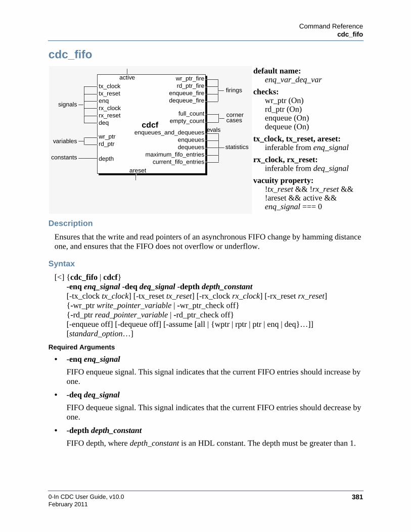
Command Referencecdc_fifo
0-In CDC User Guide, v10.0 381February 2011
cdc_fifo
Description
Ensures that the write and read pointers of an asynchronous FIFO change by hamming distanceone, and ensures that the FIFO does not overflow or underflow.
Syntax
[<] {cdc_fifo | cdcf}-enq enq_signal -deq deq_signal -depth depth_constant[-tx_clock tx_clock] [-tx_reset tx_reset] [-rx_clock rx_clock] [-rx_reset rx_reset]{-wr_ptr write_pointer_variable | -wr_ptr_check off}{-rd_ptr read_pointer_variable | -rd_ptr_check off}[-enqueue off] [-dequeue off] [-assume [all | {wptr | rptr | ptr | enq | deq}…]][standard_option…]
Required Arguments
• -enq enq_signal
FIFO enqueue signal. This signal indicates that the current FIFO entries should increase byone.
• -deq deq_signal
FIFO dequeue signal. This signal indicates that the current FIFO entries should decrease byone.
• -depth depth_constant
FIFO depth, where depth_constant is an HDL constant. The depth must be greater than 1.
default name:enq_var_deq_var
checks:wr_ptr (On)rd_ptr (On)enqueue (On)dequeue (On)
tx_clock, tx_reset, areset:inferable from enq_signal
rx_clock, rx_reset:inferable from deq_signal
vacuity property:!tx_reset && !rx_reset &&!areset && active &&enq_signal === 0
areset
tx_clock rd_ptr_firewr_ptr_fire
enqueues_and_dequeuesenqueuesdequeues
cdcf
signals
firings
statistics
active
tx_resetenq
evals
full_count cornercases
dequeue_firerx_clockrx_resetdeq
constants depth
enqueue_fire
maximum_fifo_entriescurrent_fifo_entries
empty_count
variableswr_ptrrd_ptr

0-In CDC User Guide, v10.0382
Command Referencecdc_fifo
February 2011
Inferable Options
• [-tx_clock tx_clock] [-tx_reset tx_reset]
Transmit clock and synchronous reset. If unspecified, each is inferable from enq_signal.
• [-rx_clock rx_clock] [-rx_reset rx_reset]
Receive clock and synchronous reset. If unspecified, each is inferable from deq_signal.
Checks and Related Options
• Wr_ptr check, default On
{-wr_ptr write_pointer_variable | -wr_ptr_check off}
When the value of write_pointer_variable changes, the hamming distance between theprevious and the new values must be 1. This check occurs at the active transmit clock edge.The checker fires each time write_pointer_variable improperly changes. The -wr_ptr_checkoff option disables this check.
Firing message: The value (write_pointer) has a distance more than one from the previousvalue (previous_write_pointer).
• Rd_ptr check, default On
{-rd_ptr read_pointer_variable | -rd_ptr_check off}
When the value of read_pointer_variable changes, the hamming distance between theprevious and the new values must be 1. This check occurs at the active receive clock edge.The checker fires each time read_pointer_variable improperly changes. The -rd_ptr_checkoff option disables this check.
Firing message: The value (read_pointer) has a distance more than one from the previousvalue (previous_read_pointer).
• Enqueue check, default On
[-enqueue off]
An enqueue should not occur while the FIFO is full. This check occurs at the active transmitclock edge. The checker fires each time the FIFO improperly enqueues. The -enqueue offoption disables this check.
Firing message: An enqueue occurred while the FIFO was full.
• Dequeue check, default On
[-dequeue off]
A dequeue should not occur while the FIFO is empty. This check occurs at the activereceive clock edge. The checker fires each time the FIFO improperly dequeues. The-dequeue off option disables this check.
Firing message: A dequeue occurred while the FIFO was empty.
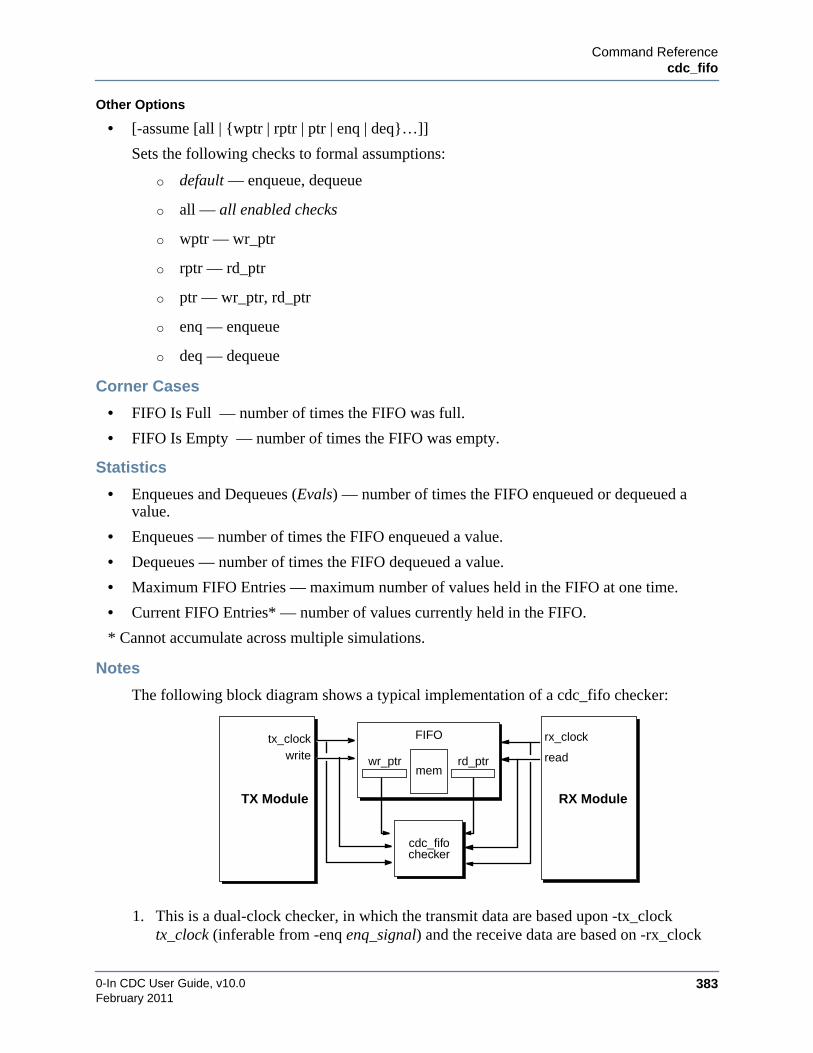
Command Referencecdc_fifo
0-In CDC User Guide, v10.0 383February 2011
Other Options
• [-assume [all | {wptr | rptr | ptr | enq | deq}…]]
Sets the following checks to formal assumptions:
o default — enqueue, dequeue
o all — all enabled checks
o wptr — wr_ptr
o rptr — rd_ptr
o ptr — wr_ptr, rd_ptr
o enq — enqueue
o deq — dequeue
Corner Cases
• FIFO Is Full — number of times the FIFO was full.
• FIFO Is Empty — number of times the FIFO was empty.
Statistics
• Enqueues and Dequeues (Evals) — number of times the FIFO enqueued or dequeued avalue.
• Enqueues — number of times the FIFO enqueued a value.
• Dequeues — number of times the FIFO dequeued a value.
• Maximum FIFO Entries — maximum number of values held in the FIFO at one time.
• Current FIFO Entries* — number of values currently held in the FIFO.
* Cannot accumulate across multiple simulations.
Notes
The following block diagram shows a typical implementation of a cdc_fifo checker:
1. This is a dual-clock checker, in which the transmit data are based upon -tx_clocktx_clock (inferable from -enq enq_signal) and the receive data are based on -rx_clock
cdc_fifochecker
FIFO
RX ModuleTX Module
tx_clock rx_clock
memrd_ptrwr_ptr readwrite

0-In CDC User Guide, v10.0384
Command Referencecdc_fifo
February 2011
rx_clock (inferable from -deq deq_signal). The standard -clock option should not bespecified.
2. Asynchronous reset for this checker can be specified using the standard -areset option. Ifthis option is not specified, then the asynchronous reset is inferred from -enqenq_signal. In either case, the reset applies to the entire checker, including logic on bothclocks.
3. This checker is synchronous with respect to each clock, so it responds only to behaviorthat is observable at the active edge of the transmit or receive clock.
Examples
/* 0in cdc_fifo -enq enq -deq deq -depth 8-wr_ptr_check off -rd_ptr_check off-enq_fire enq_fire */
Checks that the FIFO does not overflow or underflow.
/* 0in cdc_fifo -enq enq -deq deq -depth 8-wr_ptr write_ptr -wr_ptr_fire write_ptr_fire-rd_ptr read_ptr -rd_ptr_fire read_ptr_fire */
Checks that the values of write_ptr and read_ptr do not change by more than ahamming distance of 1.
3 5
tx_clk
write_ptr
enq
rx_clk
write_ptr_fire
5 4
tx_clk
read_ptr
deq
rx_clk
read_ptr_fire
3
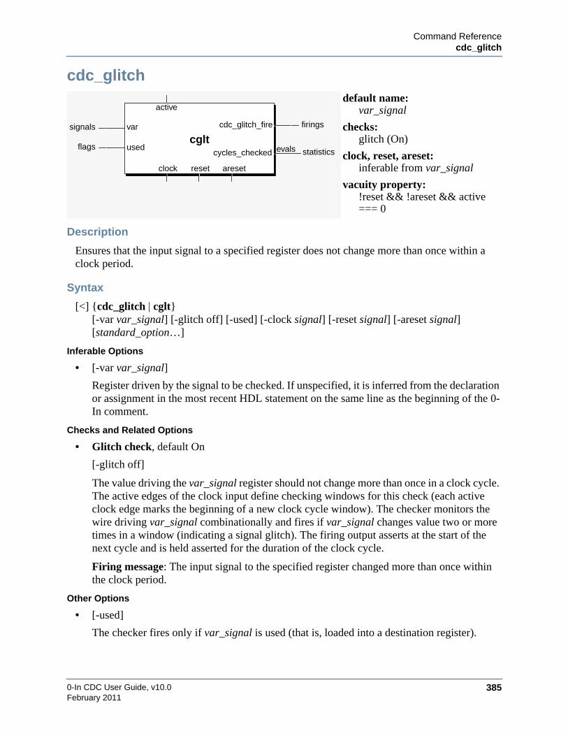
Command Referencecdc_glitch
0-In CDC User Guide, v10.0 385February 2011
cdc_glitch
Description
Ensures that the input signal to a specified register does not change more than once within aclock period.
Syntax
[<] {cdc_glitch | cglt}[-var var_signal] [-glitch off] [-used] [-clock signal] [-reset signal] [-areset signal][standard_option…]
Inferable Options
• [-var var_signal]
Register driven by the signal to be checked. If unspecified, it is inferred from the declarationor assignment in the most recent HDL statement on the same line as the beginning of the 0-In comment.
Checks and Related Options
• Glitch check, default On
[-glitch off]
The value driving the var_signal register should not change more than once in a clock cycle.The active edges of the clock input define checking windows for this check (each activeclock edge marks the beginning of a new clock cycle window). The checker monitors thewire driving var_signal combinationally and fires if var_signal changes value two or moretimes in a window (indicating a signal glitch). The firing output asserts at the start of thenext cycle and is held asserted for the duration of the clock cycle.
Firing message: The input signal to the specified register changed more than once withinthe clock period.
Other Options
• [-used]
The checker fires only if var_signal is used (that is, loaded into a destination register).
default name:var_signal
checks:glitch (On)
clock, reset, areset:inferable from var_signal
vacuity property:!reset && !areset && active=== 0
clock reset areset
var cdc_glitch_fire
cycles_checked
cgltsignals firings
statistics
active
evalsflags used

0-In CDC User Guide, v10.0386
Command Referencecdc_glitch
February 2011
Statistics
• Cycles Checked (Evals) — number of cycles checked (i.e., the number of cycles that thesignal driving var_signal changed value at least once).
Notes
1. This is an asynchronous checker that responds to combinational behavior. The clocksignal’s active edges are used to define time windows for the checker’s glitch detectionlogic.
2. Whereas the glitch checker checks for glitches on the specified -var signal, thecdc_glitch checker infers the driving logic to the specified -var register and checks forglitches on the inferred driving signal (connected to the var_d port of the cdc_glitchchecker).
Examples
// 0in cdc_glitch -var reg
Checks that the input (var_d) to the reg register does not glitch.
inferred
cdc_glitch //0in cdc_glitch -var varchecker checks
for glitch on var_d
var_d
var
connection
clk
var_d
glitch_fireglitch

Command Referencecdc_hamming_distance_one
0-In CDC User Guide, v10.0 387February 2011
cdc_hamming_distance_one
Description
Ensures that the data crossing from transmit clock to receive clock domain changes by only onehamming distance and that it remains stable for a specified tx_min clock cycles.
Syntax
[<] {cdc_hamming_distance_one | cdc_hamming1}[-tx_var tx_variable] [-tx_clock tx_clock] [-tx_reset tx_reset ][-tx_min tx_min_constant] [-hamming_one off] [-assume [all | {dist | stable}…]][standard_option…]
Inferable Options
• [-tx_var tx_variable]
Variable with the transmit data in the transmit clock domain. If unspecified, it is inferredfrom the declaration or assignment in the most recent HDL statement on the same line as thebeginning of the 0-In comment.
• [-tx_clock tx_clock][-tx_reset tx_reset]
Transmit clock and synchronous reset. If unspecified, each is inferable from tx_variable.
Checks and Related Options
• Hamming_one check, default On
[-hamming_one off]
The transmit data should only change by a hamming distance of 1. This check occurs at theactive transmit clock edge whenever the value of tx_variable changes. The checker fireseach time the hamming distance between the previous and the new tx_variable value isgreater than 1. The -hamming_one off option disables this check.
Firing message: The value (tx_variable_value) has a distance more than one from theprevious value (previous_tx_variable_value).
default name:tx_variable
checks:hamming_one (On)data_stable (Off)
tx_clock, tx_reset, areset:inferable from tx_variable
vacuity property:!tx_reset && !areset && active=== 0
areset
tx_clock
values_checkedlontgest_stable_timeshortest_stable_time
cdc_hamming1
signalsfirings
statistics
active
variables
tx_reset
tx_var evals
value_changed_at_tx_min cornercases
stable_fire
constants tx_min
hamming_one_fire

0-In CDC User Guide, v10.0388
Command Referencecdc_hamming_distance_one
February 2011
• Data_stable check, default Off
[-tx_min tx_min_constant]
The transmit data should remain stable for at least tx_min_constant cycles of the transmitclock. This check occurs at the active transmit clock edge whenever the value of tx_variablechanges. The checker fires each time the value of tx_variable changes beforetx_min_constant cycles have elapsed.
Firing message: The value changed after number_of_cycles, but the specified minimumtime to remain constant is tx_min_constant cycles.
Other Options
• [-assume [all | {dist | stable}…]]
Sets the following checks to formal assumptions:
o all (default) — all enabled checks
o dist — hamming_one
o stable — data_stable
Corner Cases
• Value Changed at ’tx_min’ — number of times tx_variable changed at tx_min_constantcycles. Reported only if the data_stable check is enabled.
Statistics
• Values Checked (Evals) — number of values checked.
• Longest Stable Time — most number of cycles tx_variable remained stable.
• Shortest Stable Time — fewest number of cycles tx_variable remained stable.
Notes
1. This is a dual-clock checker, in which the transmit data are based upon -tx_clocktx_clock (inferable from -tx_var tx_variable) and the receive clock is unused. Thestandard -clock option should not be specified.
2. Asynchronous reset for this checker can be specified using the standard -areset option. Ifthis option is not specified, then the asynchronous reset is inferred from -tx_vartx_variable. In either case, the reset applies to the entire checker, including logic on bothclocks.
3. This checker is synchronous with respect to the transmit clock, so it responds only tobehavior that is observable at the active edge of the transmit clock.

Command Referencecdc_hamming_distance_one
0-In CDC User Guide, v10.0 389February 2011
Examples
/* 0in cdc_hamming_distance_one -tx_var tx_var-hamming_one_fire hamming_one_fire */
Checks that the value of tx_var only changes by a hamming distance of 1.
/* 0in cdc_hamming_distance_one -tx_var tx_var-tx_min 3 -stable_fire stable_fire */
Checks that each time the value of tx_var changes, the data remains stable for at least3 cycles of the transmit domain clock.
0011 0101
tx_clk
tx_var
hamming_one_fire
rx_clk
0101 1100
tx_clk
tx_var
rx_clk
stable_fire
0100
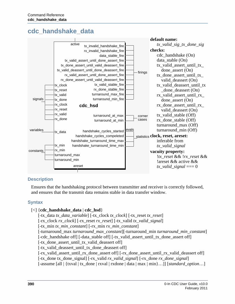
0-In CDC User Guide, v10.0390
Command Referencecdc_handshake_data
February 2011
cdc_handshake_data
Description
Ensures that the handshaking protocol between transmitter and receiver is correctly followed,and ensures that the transmit data remains stable in data transfer window.
Syntax
[<] {cdc_handshake_data | cdc_hsd}[-tx_data tx_data_variable] [-tx_clock tx_clock] [-tx_reset tx_reset][-rx_clock rx_clock] [-rx_reset rx_reset] [-tx_valid tx_valid_signal][-tx_min tx_min_constant] [-rx_min rx_min_constant][-turnaround_max turnaround_max_constant][-turnaround_min turnaround_min_constant][-cdc_handshake off] [-data_stable off] [-tx_valid_assert_until_tx_done_assert off][-tx_done_assert_until_tx_valid_deassert off][-tx_valid_deassert_until_tx_done_deassert off][-rx_valid_assert_until_rx_done_assert off] [-rx_done_assert_until_rx_valid_deassert off][-tx_done tx_done_signal] [-rx_valid rx_valid_signal] [-rx_done rx_done_signal][-assume [all | {txval | tx_done | rxval | rxdone | data | max | min}…]] [standard_option…]
default name:tx_valid_sig_tx_done_sig
checks:cdc_handshake (On)data_stable (On)tx_valid_assert_until_tx_
done_assert (On)tx_done_assert_until_tx_
valid_deassert (On)tx_valid_deassert_until_tx
_done_deassert (On)rx_valid_assert_until_rx_
done_assert (On)rx_done_assert_until_rx_
valid_deassert (On)tx_valid_stable (Off)rx_done_stable (Off)turnaround_max (Off)turnaround_min (Off)
clock, reset, areset:inferable fromtx_valid_signal
vacuity property:!tx_reset && !rx_reset &&!areset && active &&tx_valid_signal === 0areset
tx_clock
handshake_cycles_started
cdc_hsd
signals
statistics
active
variables
tx_reset
tx_dataevals
turnaround_at_max cornercases
tx_invalid_handshake_fire
tx_valid
rx_clockrx_resetrx_valid
constants
tx_min
tx_valid_assert_until_done_assert_firetx_done_assert_until_valid_deassert_fire
tx_valid_deassert_until_done_deassert_fire
rx_invalid_handshake_fire
rx_valid_assert_until_done_assert_firerx_done_assert_until_valid_deassert_fire
data_stable_fire
tx_valid_stable_firerx_done_stable_fire
turnaround_max_fireturnaround_min_fire
firings
turnaround_at_min
handshake_cycles_compeletedhandshake_turnaround_time_maxhandshake_turnaround_time_min
tx_done
rx_done
rx_minturnaround_maxturnaround_min

Command Referencecdc_handshake_data
0-In CDC User Guide, v10.0 391February 2011
Inferable Options
• [-tx_data tx_data_variable]
Variable with the transmit data in the transmit clock domain. This variable is used with thecdc_handshake, data_stable and turnaround checks. If one of these checks is on and -tx_datais unspecified, it is inferred from the declaration or assignment in the most recent HDLstatement on the same line as the beginning of the 0-In comment.
If transmit data bus is not available, you must turn off the cdc_handshake and data_stablechecks.
• [-tx_clock tx_clock] [-tx_reset tx_reset]
Transmit clock and synchronous reset. If unspecified, each is inferred from tx_valid_signal.
• [-rx_clock rx_clock] [-rx_reset rx_reset]
Receive clock and synchronous reset. If unspecified, each is inferred from rx_done_signal.
• [-tx_valid tx_valid_signal]
Signal that indicates the transmit data in the transmit clock domain is valid. This signal isused with the cdc_handshake, data_stable, tx_* and turnaround checks. If one of thesechecks is on and -tx_valid is unspecified, it is inferred from the declaration or assignment inthe most recent HDL statement on the same line as the beginning of the 0-In comment.
If transmit valid signal is not available, you must turn off the cdc_handshake, data_stableand *_tx_valid_* checks.
Checks and Related Options
• Cdc_handshake check, default On
[-cdc_handshake off]
The handshake protocol must remain in a known state. This check requirestx_data_variable, tx_valid_signal, tx_done_signal, rx_valid_signal and rx_done_signal.This check occurs at the active transmit clock edge. The checker fires each time thehandshake protocol is violated by the transmitter. A violation asserts eithertx_invalid_handshake_fire or rx_invalid_handshake_fire. The -cdc_handshake off optionturns off this check.
Firing message: Handshake protocol was not followed properly by transmitter.
Firing message: Handshake protocol was not followed properly by receiver.
• Data_stable check, default On
[-data_stable off]
The transmit data (tx_data_variable) must be held stable in the data transfer window, whichopens when tx_valid_signal asserts and closes when tx_done_signal asserts. This checkrequires tx_data_variable, tx_valid_signal and tx_done_signal. This check occurs at theactive transmit clock edge. The checker fires each time the value of tx_data_variable issampled changed in the data transfer window. The -data_stable off option turns off thischeck.

0-In CDC User Guide, v10.0392
Command Referencecdc_handshake_data
February 2011
Firing message: ’tx_data’ changed from previous_value to value in the data transferwindow.
• Tx_valid_assert_until_tx_done_assert check, default On
[-tx_valid_assert_until_tx_done_assert off]
The tx_valid_signal signal, once asserted, must remain asserted until tx_done is received.This check requires tx_valid_signal and tx_done_signal. This check occurs at the activetransmit clock edge whenever a data transfer window is open. The checker fires each timetx_valid_signal deasserts before tx_done_signal is sampled asserted. The-tx_valid_assert_until_tx_done_assert off option turns off this check.
Firing message: ’tx_valid’ deasserted before ’tx_done’ was received.
• Tx_done_assert_until_tx_valid_deassert check, default On
[-tx_done_assert_until_tx_valid_deassert off]
The tx_done_signal must remain asserted until tx_valid_signal deasserts. This checkrequires tx_valid_signal and tx_done_signal. This check occurs at the active transmit clockedge whenever a data transfer window is open. The checker fires each time tx_done_signaldeasserts before tx_valid_signal deasserts. The -tx_done_assert_until_tx_valid_deassert offoption turns off this check.
Firing message: ’tx_done’ deasserted before ’tx_valid’ deasserted.
• Tx_valid_deassert_until_tx_done_deassert check, default On
[-tx_valid_deassert_until_tx_done_deassert off]
The tx_valid_signal must not assert again until the current tx_done_signal deassertscompleting the current data transfer cycle. This check requires tx_valid_signal andtx_done_signal. This check occurs at the active transmit clock edge whenever a data transferwindow is open. The checker fires each time tx_valid_signal reasserts beforetx_done_signal deasserts to close the data transfer window. The-tx_valid_deassert_until_tx_done_deassert off option turns off this check.
Firing message: New ’tx_valid’ asserted before current ’tx_done’ deasserted to completethe current data transfer cycle.
• Rx_valid_assert_until_rx_done_assert check, default On
[-rx_valid_assert_until_rx_done_assert off]
The rx_valid_signal signal, once asserted, must remain asserted until rx_done is received.This check requires rx_valid_signal and rx_done_signal. This check occurs at the activereceive clock edge whenever a data transfer window is open. The checker fires each timerx_valid_signal deasserts before rx_done_signal is sampled asserted. The-rx_valid_assert_until_rx_done_assert off option turns off this check.
Firing message: ’rx_valid’ deasserted before ’rx_done’ was received.

Command Referencecdc_handshake_data
0-In CDC User Guide, v10.0 393February 2011
• Rx_done_assert_until_rx_valid_deassert check, default On
[-rx_done_assert_until_rx_valid_deassert off]
The rx_done_signal must remain asserted until rx_valid_signal deasserts. This checkrequires rx_valid_signal and rx_done_signal. This check occurs at the active transmit clockedge whenever a data transfer window is open. The checker fires each time rx_done_signaldeasserts before rx_valid_signal deasserts. The -rx_done_assert_until_rx_valid_deassert offoption turns off this check.
Firing message: ’rx_done’ deasserted before ’rx_valid’ deasserted.
• Tx_valid_stable check, default Off
[-tx_min tx_min_constant]
The tx_valid_signal signal must be held stable for at least tx_min_constant transmit clocks.This check requires tx_valid_signal and is turned on by the -tx_min tx_min_constant option.This check occurs at the active transmit clock edge whenever tx_valid_signal deasserts. Thechecker fires each time tx_valid_signal deasserts prematurely.
Firing message: ’tx_valid’ changed after number_of_cycles cycles, but the specifiedminimum time to remain constant is tx_min cycles.
• Rx_done_stable check, default Off
[-rx_min rx_min_constant]
The rx_done_signal signal must be held stable for at least rx_min_constant receive clocks.This check requires rx_done_signal and is turned on by the -rx_min rx_min_constantoption. This check occurs at the active receive clock edge whenever rx_done_signaldeasserts. The checker fires each time rx_valid signnal deasserts prematurely.
Firing message: ’rx_done’ changed after number_of_cycles cycles, but the specifiedminimum time to remain constant is rx_min cycles.
• Turnaround_min check, default Off
[-turnaround_min turnaround_min_constant]
Each data handshake protocol cycle must not complete in fewer thanturnaround_min_constant transmit clock cycles. This check requires tx_data_variable,tx_valid_signal, tx_done_signal, rx_valid_signal and rx_done_signal and is turned on bythe -turnaround_min turnaround_min_constant option. This check occurs at the activetransmit clock edge whenever the data transfer window closes. The checker fires each timethe data transfer window closes before turnaround_min_constant transmit clock cycles.
Firing message: Data transfer handshake cycle completed in number_of_cycles cycles, butthe specified minimum turnaround time is turnaround_min cycles.
• Turnaround_max check, default Off
[-turnaround_max turnaround_max_constant]
Each data handshake protocol cycle must not complete in more thanturnaround_max_constant transmit clock cycles. This check requires tx_data_variable,

0-In CDC User Guide, v10.0394
Command Referencecdc_handshake_data
February 2011
tx_valid_signal, tx_done_signal, rx_valid_signal and rx_done_signal and is turned on bythe -turnaround_max turnaround_max_constant option. This check occurs at the activetransmit clock edge. The checker fires each cycle the data transfer lasts more thanturnaround_min_constant transmit clock cycles.
Firing message: Data transfer handshake cycle completed in number_of_cycles cycles, butthe specified maximum turnaround time is turnaround_max cycles.
Other Options
• [-tx_done tx_done_signal]
Signal that indicates data transmission is complete. This signal is required for thecdc_handshake, data_stable, tx and turnaround checks.
• [-rx_valid rx_valid_signal]
Signal that indicates the receive data in the receive clock domain is valid. This signal is usedwith the cdc_handshake, data_stable, rx and turnaround checks.
• [-rx_done rx_done_signal]
Signal that indicates data reception is complete. This signal is required for thecdc_handshake, data_stable, rx and turnaround checks.
NoteImportant: If the rx_valid and rx_done signals are not available, you must turn off thecdc_handshake, rx_valid_assert_until_rx_done_assert andrx_done_assert_until_rx_valid_deassert checks.
• [-assume [all | {txval | tx_done | rxval | rxdone | data | max | min}…]]
Sets the following checks to formal assumptions:
o default — cdc_handshake
o all — all enabled checks
o txval — tx_valid_assert_until_tx_done_assert,tx_valid_deassert_until_tx_done_deassert, tx_valid_stable, cdc_handshake
o txdone — tx_done_assert_until_tx_valid_deassert, cdc_handshake
o rxval — rx_valid_assert_until_rx_done_assert, cdc_handshake
o rxdone — rx_done_assert_until_rx_valid_deassert, rx_done_stable, cdc_handshake
o data — data_stable, cdc_handshake
o max — turnaround_max, cdc_handshake
o min — turnaround_min, cdc_handshake

Command Referencecdc_handshake_data
0-In CDC User Guide, v10.0 395February 2011
Corner Cases
• Turnaround Cycles Completed at ’turnaround_max’— number of times a data transfercompleted in exactly turnaround_max_constant transmit clock cycles.
• Turnaround Cycles Completed at ’turnaround_min’— number of times a data transfercompleted in exactly turnaround_max_constant transmit clock cycles.
Statistics
• Total Tx_valid (Evals) — number of times tx_valid_signal was asserted, starting a new datatransfer cycle.
• Total Turnaround Cycles — number of data transfer cycles completed.
• Maximum Turnaround Cycles — maximum number of transmit clock cycles taken for acomplete data transfer cycle.
• Minimum Turnaround Cycles — minimum number of transmit clock cycles taken for acomplete data transfer cycle.
Notes
The following block diagram shows a typical implementation of a cdc_handshake_datachecker:
1. This is a dual-clock checker, in which the transmit data are based upon -tx_clocktx_clock (inferable from -tx_valid tx_valid_signal) and the receive data are based on-rx_clock rx_clock (inferable from -rx_done rx_done_signal). The standard -clockoption should not be specified.
2. Asynchronous reset for this checker can be specified using the standard -areset option. Ifthis option is not specified, then the asynchronous reset is inferred from -tx_validtx_valid_signal. In either case, the reset applies to the entire checker, including logic onboth clocks.
3. This checker is synchronous with respect to each clock, so it responds only to behaviorthat is observable at the active edge of the transmit or receive clock.
cdc_handshake_datachecker
Rx SYNC
RX ModuleTX Module
data
tx_valid
tx_data
Tx SYNCtx_done
rx_valid
rx_data
rx_done
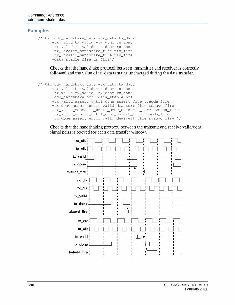
0-In CDC User Guide, v10.0396
Command Referencecdc_handshake_data
February 2011
Examples
/* 0in cdc_handshake_data -tx_data tx_data-tx_valid tx_valid -tx_done tx_done-rx_valid rx_valid -rx_done rx_done-tx_invalid_handshake_fire tih_fire-rx_invalid_handshake_fire rih_fire-data_stable_fire ds_fire*/
Checks that the handshake protocol between transmitter and receiver is correctlyfollowed and the value of tx_data remains unchanged during the data transfer.
/* 0in cdc_handshake_data -tx_data tx_data-tx_valid tx_valid -tx_done tx_done-rx_valid rx_valid -rx_done rx_done-cdc_handshake off -data_stable off-tx_valid_assert_until_done_assert_fire tvauda_fire-tx_done_assert_until_valid_deassert_fire tdauvd_fire-tx_valid_deassert_until_done_deassert_fire tvdudd_fire-rx_valid_assert_until_done_assert_fire rvauda_fire-rx_done_assert_until_valid_deassert_fire rdauvd_fire */
Checks that the handshaking protocol between the transmit and receive valid/donesignal pairs is obeyed for each data transfer window.
tx_clk
tx_valid
tx_done
rx_clk
tvauda_fire
tx_clk
tx_valid
tx_done
rx_clk
tdauvd_fire
tx_clk
tx_valid
tx_done
rx_clk
tvdudd_fire

Command Referencecdc_handshake_data
0-In CDC User Guide, v10.0 397February 2011
/* 0in cdc_handshake_data-tx_valid tx_valid -tx_min 5 -rx_done rx_done -rx_min3-cdc_handshake off -data_stable off-tx_valid_assert_until_done_assert_fire off-tx_done_assert_until_valid_deassert_fire off-tx_valid_deassert_until_done_deassert_fire off-rx_valid_assert_until_done_assert_fire off-rx_done_assert_until_valid_deassert_fire off-tx_valid_stable_fire tvs_fire-rx_done_stable_fire rds_fire */
Checks that tx_valid is held constant for at least 4 transmit clock cycles and thatrx_done is held constant for at least 2 receive clock cycles.
/* 0in cdc_handshake_data -tx_data tx_data-tx_valid tx_valid -tx_done tx_done-rx_valid rx_valid -rx_done rx_done-turnaround_min 10 -turnaround_max 16*/
Checks that the handshake protocol between transmitter and receiver is correctlyfollowed and the value of tx_data remains unchanged during the data transfer. Alsochecks that the handshaking protocol between the transmit and receive valid/donesignal pairs is obeyed for each data transfer window. Also checks that every datatransfer cycle lasts at least 10, but no more than 16, transmit clock cycles.
tx_clk
rx_valid
rx_done
rx_clk
rvauda_fire
tx_clk
rx_valid
rx_done
rx_clk
rdauvd_fire
tx_clk
tx_valid
rx_done
rx_clk
tvs_fire
rds_fire

0-In CDC User Guide, v10.0398
Command Referencecdc_sample
February 2011
cdc_sample
Description
Ensures that data between two clock domains remain stable in the transmit domain for onereceive clock cycle before and one receive clock cycle after it is sampled in the receive domain.(i.e., the receive domain samples at least twice for each transmit signal so that the correct valueis sampled).
Syntax
[<] {cdc_sample | sample}-tx_var tx_variable -rx_var rx_variable [-tx_clock tx_clock] [-tx_reset tx_reset][-rx_clock rx_clock] [-rx_reset rx_reset] [-setup off] [-hold off] [-assume][standard_option…]
Required Arguments
• -tx_var tx_variable
Source variable in the transmit clock domain.
• -rx_var rx_variable
Destination variable in the receive clock domain.
Inferable Options
• [-tx_clock tx_clock] [-tx_reset tx_reset]
Transmit clock and synchronous reset. If unspecified, each is inferable from tx_variable.
• [-rx_clock rx_clock] [-rx_reset rx_reset]
Receive clock and synchronous reset. If unspecified, each is inferable from rx_variable.
default name:tx_var_rx_var
checks:setup (On)hold (On)
tx_clock, tx_reset, areset:inferable from tx_variable
rx_clock, rx_reset:inferable from rx_variable
vacuity property:!tx_reset && !rx_reset &&!areset && active &&rx_enable_signal === 0
areset
tx_clockhold_fire
setup_fire
values_sampledsample_zero_bitmapsample_one_bitmap
sample
signals
firings
statistics
active
tx_reset
evals
all_onecornercasesrx_clock
rx_reset
variablestx_var
one_to_zero_transition_bitmapzero_to_one_transition_bitmap
all_zeroall_zero_to_oneall_one_to_zero
rx_var

Command Referencecdc_sample
0-In CDC User Guide, v10.0 399February 2011
Checks and Related Options
• Setup check, default On
[-setup off]
For every cycle that rx_variable is sampled, the value of tx_variable must remain constantfrom the previous active transmit clock edge to the active receive clock edge at which thevalue of rx_variable is sampled. This check occurs at the active rx_clock edge wheneverrx_variable is sampled. The checker fires each time tx_variable has improperly changed.The -setup off option turns off this check.
Firing message: The transmit data were unstable before being sampled in the receive clockdomain.
• [-hold off]
For every cycle that rx_variable is sampled, the value of tx_variable must remain constantfrom the active receive clock edge at which the value of rx_variable is sampled to the nextactive transmit or receive clock edge (whichever is earlier). This check occurs at the activerx_clock edge whenever rx_variable has been sampled at the previous active rx_clock edge.The checker fires each time tx_variable has improperly changed. The -hold off option turnsoff this check.
Firing message: The transmit data was unstable after being sampled in the receive clockdomain.
Other Options
• [-assume]
Sets all enabled checks to formal assumptions.
Corner Cases
• All Zero — non-zero if every bit of rx_variable was sampled as 0.
• All One — non-zero if every bit of rx_variable was sampled as 1.
• All One to Zero — non-zero if every bit of rx_variable was sampled transitioning from1 to 0 (that is, all bits of One to Zero Transition Bitmap are 1).
• All Zero to One — non-zero if every bit of rx_variable was sampled transitioning from0 to 1 (that is, all bits of Zero to One Transition Bitmap are 1).
Statistics
• Values Sampled (Evals) — number of times rx_variable was checked.
• Sample Zero Bitmap — bit vector representing which bits of rx_variable were sampledas 0.
• Sample One Bitmap — bit vector representing which bits of rx_variable were sampledas 1.

0-In CDC User Guide, v10.0400
Command Referencecdc_sample
February 2011
• One to Zero Transition Bitmap — bit vector representing which bits of rx_variable weresampled transitioning from 1 to 0.
• Zero to One Transition Bitmap — bit vector representing which bits of rx_variable weresampled transitioning from 0 to 1.
If more than 32 bits are specified, the bitmaps are displayed as hexadecimal values.
Notes
The following block diagram shows a typical implementation of a cdc_sample checker:
1. This is a dual-clock checker, in which the transmit data are based upon -tx_clocktx_clock and the receive data are based on -rx_clock rx_clock. The standard -clockoption should not be specified.
2. Asynchronous reset for this checker can be specified using the standard -areset option. Ifthis option is not specified, then the asynchronous reset is inferred from -tx_vartx_variable. In either case, the reset applies to the entire checker, including logic on bothclocks.
3. The cdc_sample checker has an rx_enable port with an inferred connection to thesampling condition used to sample tx_variable in the receive clock domain. If therx_enable connection cannot be inferred, the checker is excluded (directive-166warning).
Examples
/* 0in cdc_sample-tx_var tx_var -tx_clock tx_clk-rx_var rx_var -rx_clock rx_clk-setup_fire setup_fire -hold_fire hold_fire */
Checks that tx_var remains stable for the tx_clk cycle preceding, and for the tx_clkcycle after, each rx_clk edge at which rx_var is sampled.
cdc_samplechecker
TX Regtx_var
tx_clk rx_clk
RX Regrx_var_d rx_var
tx_clk
tx_var
rx_enable
rx_clk
hold_fire
setup_fire
AA A5 C5
(inferred)

Command Referencecdc_sync
0-In CDC User Guide, v10.0 401February 2011
cdc_sync
Description
Ensures that a clock domain crossing signal from a faster clock to a slower clock is held stablelong enough for the signal to be sampled reliably by the receiver.
Syntax
[<] {cdc_sync | sync}[-tx_var tx_variable] [-tx_clock tx_clock] [-tx_reset tx_reset] [-stable off][-tx_min tx_min_constant] [-assume] [standard_option*…]
Inferable Options
• [-tx_var tx_variable]
Variable with the transmit data in the transmit clock domain. If unspecified, it is inferredfrom the declaration or assignment in the most recent HDL statement on the same line as thebeginning of the 0-In comment.
• [-tx_clock tx_clock] [-tx_reset tx_reset]
Transmit clock and synchronous reset. If unspecified, each is inferable from tx_variable.
Checks and Related Options
• Stable check, default On
[-stable off]
The transmit data should remain stable for at least tx_min_constant cycles of the transmitclock. This check occurs at the active transmit clock edge whenever the value of tx_variablechanges. The checker fires each time the value of tx_variable changes beforetx_min_constant cycles have elapsed. The -stable off option disables this check.
Firing message: ’tx_var’ changed after number_of_cycles cycles, but the specifiedminimum time to remain constant is tx_min_constant cycles.
default name:tx_variable
checks:stable (On)
tx_clock, tx_reset, areset:inferable from tx_variable
vacuity property:!tx_reset && !areset &&active === 0
* one checker is instantiated for each tx_var bit
areset
tx_clock
values_checkedshortest_stable_timelongest_stable_time
syncsignals
firings
statistics
active
tx_reset
tx_var[n]*
evals
value_changed_at_tx_min cornercases
constants tx_min
stable_fire
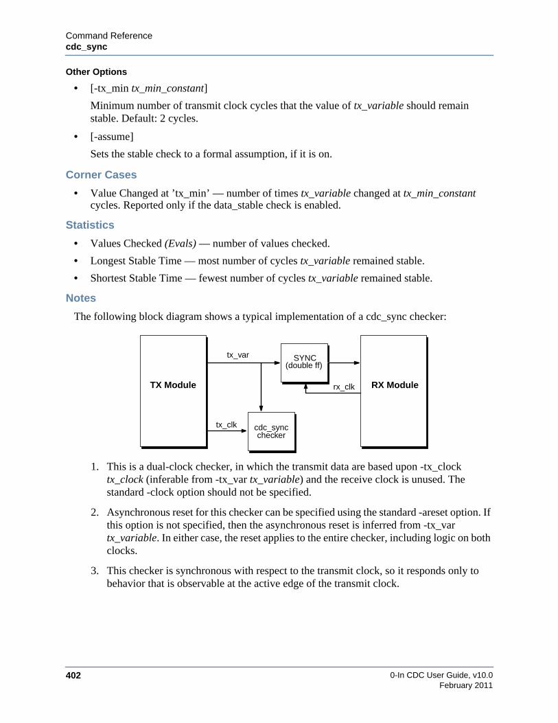
0-In CDC User Guide, v10.0402
Command Referencecdc_sync
February 2011
Other Options
• [-tx_min tx_min_constant]
Minimum number of transmit clock cycles that the value of tx_variable should remainstable. Default: 2 cycles.
• [-assume]
Sets the stable check to a formal assumption, if it is on.
Corner Cases
• Value Changed at ’tx_min’ — number of times tx_variable changed at tx_min_constantcycles. Reported only if the data_stable check is enabled.
Statistics
• Values Checked (Evals) — number of values checked.
• Longest Stable Time — most number of cycles tx_variable remained stable.
• Shortest Stable Time — fewest number of cycles tx_variable remained stable.
Notes
The following block diagram shows a typical implementation of a cdc_sync checker:
1. This is a dual-clock checker, in which the transmit data are based upon -tx_clocktx_clock (inferable from -tx_var tx_variable) and the receive clock is unused. Thestandard -clock option should not be specified.
2. Asynchronous reset for this checker can be specified using the standard -areset option. Ifthis option is not specified, then the asynchronous reset is inferred from -tx_vartx_variable. In either case, the reset applies to the entire checker, including logic on bothclocks.
3. This checker is synchronous with respect to the transmit clock, so it responds only tobehavior that is observable at the active edge of the transmit clock.
cdc_syncchecker
SYNC
RX ModuleTX Module
tx_var
tx_clk
rx_clk
(double ff)
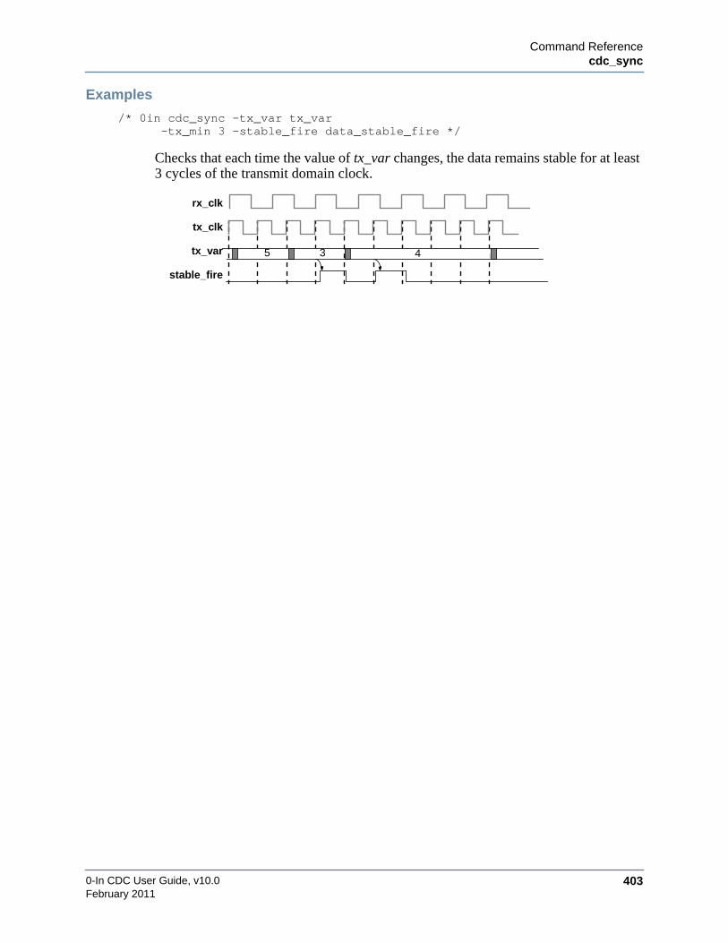
Command Referencecdc_sync
0-In CDC User Guide, v10.0 403February 2011
Examples
/* 0in cdc_sync -tx_var tx_var-tx_min 3 -stable_fire data_stable_fire */
Checks that each time the value of tx_var changes, the data remains stable for at least3 cycles of the transmit domain clock.
5 4
tx_clk
tx_var
rx_clk
stable_fire
3

0-In CDC User Guide, v10.0404
Command Referencecdc_fx
February 2011
cdc_fx
Description
Injects metastability at the output of a receive register.
Syntax
[<] {cdc_fx | cfx}-rx_reg rx_register_variable -tx_reg tx_register_variable[-rx_clock rx_clock] [-tx_clock tx_clock] [-rx_reset rx_reset] [-rx_areset rx_areset][-rx_load_enable value] [-cdc_fx] [-glitch_caught] [-glitch_swallowed][standard_option…]
Required Arguments
• -rx_reg rx_register_variable
Receiving register in the receive clock domain.
• -tx_reg tx_register_variable
Transmitting register in the transmit clock domain. The tx_register_variable can be aconcatenation of source registers for the receiving register (for example, {tx_reg3, tx_reg2,tx_reg1}).
default name:rx_reg
checks:cdc_fx (Off)glitch_swallowed (Off)glitch_caught (Off)
tx_clock, tx_reset, areset:inferable from rx_reg
vacuity property:!tx_reset && !areset &&active === 0
tx_clock
metastable_cycles
cfxsignals
statistics
active
all_bits_inverted cornercases
rx_clockrx_reset
glitch_caught_firefirings
rx_clock_before_tx_clocktx_clock_before_rx_clock
bits_inverted
rx_areset
rx_load_enable
rx_q
rx_regvalue
tx_clock
tx_reg rx_reg
rx_clock
delayed_transitionsadvanced_transitions
evals
tx_regrx_reg
monitorclocks
cdc_fx_fire
inverted_bits_bitmap
glitch_swallowed_fire
loading_while_clocks_aligned
loading_while_rx_clock_before_tx_clockloading_while_tx_clock_before_rx_clock
clocks_aligned_cycles
clks_aligned[65:0]
Command Referencecdc_fx
0-In CDC User Guide, v10.0 405February 2011
Inferable Options
• -rx_clock rx_clock
Receive clock. If unspecified, then it is inferred from rx_register_variable.
• -tx_clock tx_clock
Transmit clock. If unspecified, then it is inferred from tx_register_variable.
• -rx_reset rx_reset
Receive synchronous reset. If unspecified, then it is inferred from rx_register_variable.
• -rx_areset rx_areset
Receive asynchronous reset. If unspecified, then it is inferred from rx_register_variable.
• -rx_load_enable value
Asserted when rx_reg is loaded with valid data. If unspecified, then it is inferred fromrx_register_variable.
Checks and Related Options
• cdc_fx Check, Default Off
-cdc_fx
Ensures the data output of the transmitting register is stable in the receiving register’smetastability window. Typically, the data output of the transmit register can change value inthe receive register’s metastability window. This change can cause metastability of thereceiving register’s output, but the circuit is hopefully tolerant of this effect. However, an adhoc synchronizer might presume the transmit logic prevents the transmitting register fromchanging value in the receiving register’s metastability window. Therefore, the ad hocsynchronizer logic assumes the receiving register cannot become metastable. In this case,the cdc_fx check can be used to verify the transmit value is held stable whenever thetransmit/receive clocks are aligned. Here, the cdc_fx check is a transmit protocol check forthe ad hoc synchronizer.
This check fires when any of the bits in the receive register is metastable. Default: fx checksare on for multi_bits, dmux, simple_dmux, multi_sync_mux_select, handshake and no_syncschemes; fx checks are off for all other schemes.
Firing message: Data changed in metastability window.
• glitch_caught Check, Default Off
-glitch_caught
Ensures metastability injection does not cause a glitch at the rx_reg input to be reflected as apulse at the rx_reg output unless the glitch is also caught in simulation (see Figure 6-5 onpage 406). The check fires at the second active receive clock edge after the glitch. Thecheck reports a bitmap showing those rx_reg bits that had a glitch caught.
Firing message: Glitch detected at the receiver output. Glitched output bitmap:glitch_caught_bitmap.

0-In CDC User Guide, v10.0406
Command Referencecdc_fx
February 2011
• glitch_swallowed Check, Default Off
-glitch_swallowed
Ensures metastability injection does not cause a glitch at the rx_reg input to be swallowed(that is, missed) at the rx_reg output unless the glitch is also swallowed in simulation (seeFigure 6-5). The check fires at the second active receive clock edge after the glitch. Thecheck reports a bitmap showing those rx_reg bits that had a glitch swallowed.
Firing message: Glitch swallowed by receiver output. Swallowed glitch bitmap:glitch_swallowed_bitmap.
Figure 6-5. Transmit Protocol Checks for Glitches
tx_clock
tx_reg rx_reg
rx_clock
d q_sim
cdc_fx checker
rx_q
tx_clk
rx_clk
d
q_sim
rx_q
glitch_caught_fire
metastabilitynot injected
metastabilityinjected
Glitch_caught Check
tx_clk
rx_clk
d
q_sim
rx_q
glitch_swallowed_fire
metastabilitynot injected
metastabilityinjected
Glitch_swallowed Check
glitch
glitch
Command Referencecdc_fx
0-In CDC User Guide, v10.0 407February 2011
Corner Cases
• All Bits Inverted — nonzero if every output bit of the receive register has had metastabilityinserted.
• Loading While Clocks Aligned — number of clocks aligned cycles in whichrx_register_variable is loading.
Statistics
• Clocks Aligned Cycles (Evals) — number of clocks aligned cycles in whichtx_register_variable is changing.
• Metastable Cycles — number of clocks aligned cycles in which tx_register_variable ischanging and rx_register_variable is loading.
• Rx_clock Before Tx_clock — number of receive clocks cycles in which rx_clock goesactive before tx_clock and tx_register_variable is changing.
• Tx_clock Before Rx_clock — number of clocks aligned cycles in which tx_clock goesactive before rx_clock and tx_register_variable is changing.
• Loading While Rx_clock Before Tx_clock — number of clocks aligned cycles in whichrx_clock goes active before tx_clock, tx_register_variable is changing andrx_register_variable is loading.
• Loading While Tx_clock Before Rx_clock — number of clocks aligned cycles in whichtx_clock goes active before rx_clock, tx_register_variable is changing andrx_register_variable is loading.
• Delayed Transitions — number of times metastability injection delayed a transition until thenext cycle.
• Advanced Transitions — number of times metastability injection advanced a transition tothe current cycle.
• Bits Inverted — number of bits of the receive register output that had metastability inserted(that is, the number of 1s in the inverted bits bitmap).
• Inverted Bits Bitmap — bitmap of the bits that had metastability injected.
Notes
1. The following statistics and corner case are updated each cycle: Clocks Aligned Cycles,Tx_clock Before Rx_clock, Rx_clock Before Tx_clock, and Loading While ClocksAligned. The other statistics and corner case are updated only if the rx_register_variableis loaded.
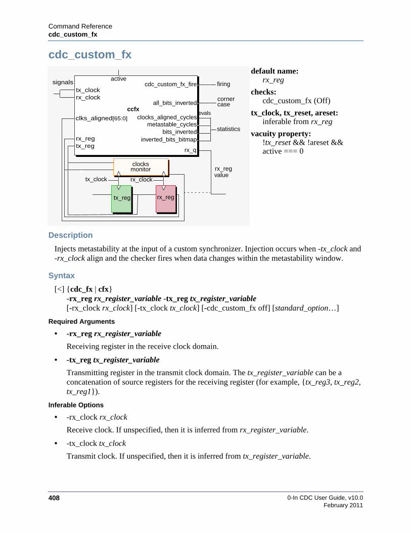
0-In CDC User Guide, v10.0408
Command Referencecdc_custom_fx
February 2011
cdc_custom_fx
Description
Injects metastability at the input of a custom synchronizer. Injection occurs when -tx_clock and-rx_clock align and the checker fires when data changes within the metastability window.
Syntax
[<] {cdc_fx | cfx}-rx_reg rx_register_variable -tx_reg tx_register_variable[-rx_clock rx_clock] [-tx_clock tx_clock] [-cdc_custom_fx off] [standard_option…]
Required Arguments
• -rx_reg rx_register_variable
Receiving register in the receive clock domain.
• -tx_reg tx_register_variable
Transmitting register in the transmit clock domain. The tx_register_variable can be aconcatenation of source registers for the receiving register (for example, {tx_reg3, tx_reg2,tx_reg1}).
Inferable Options
• -rx_clock rx_clock
Receive clock. If unspecified, then it is inferred from rx_register_variable.
• -tx_clock tx_clock
Transmit clock. If unspecified, then it is inferred from tx_register_variable.
default name:rx_reg
checks:cdc_custom_fx (Off)
tx_clock, tx_reset, areset:inferable from rx_reg
vacuity property:!tx_reset && !areset &&active === 0
tx_clock
metastable_cycles
ccfx
signals
statistics
active
all_bits_invertedcornercase
rx_clock
firing
bits_inverted
rx_q
rx_regvalue
tx_clock
tx_reg rx_reg
rx_clock
evals
tx_regrx_reg
monitorclocks
cdc_custom_fx_fire
inverted_bits_bitmap
clocks_aligned_cyclesclks_aligned[65:0]

Command Referencecdc_custom_fx
0-In CDC User Guide, v10.0 409February 2011
Checks and Related Options
• cdc_custom_fx Check, Default On
-cdc_custom_fx off
Ensures the data output of the transmitting register is stable in the receiving register’smetastability window. Typically, the data output of the transmit register can change value inthe receive register’s metastability window. This change can cause metastability of thereceiving register’s output, but the circuit is hopefully tolerant of this effect. The-cdc_custom_fx off option disables this check.
This check fires when any of the bits in the receive register is metastable.
Firing message: Data changed in metastability window.
Corner Cases
• All Bits Inverted — nonzero if every output bit of the receive register has had metastabilityinserted.
Statistics
• Clocks Aligned Cycles (Evals) — number of clocks aligned cycles in whichtx_register_variable is changing.
• Metastable Cycles — number of clocks aligned cycles in which tx_register_variable ischanging and rx_register_variable is loading.
• Bits Inverted — number of bits of the receive register output that had metastability inserted(that is, the number of 1s in the inverted bits bitmap).
• Inverted Bits Bitmap — bitmap of the bits that had metastability injected.
Notes
• Clocks Aligned Cycles is updated each cycle. The other statistics and corner case areupdated only if the rx_register_variable is loaded.
• clks_aligned[65:0]
When the assertion compiler instantiates a cdc_custom_fx checker, it also creates clockmonitor logic that determines when the transmit clock is within the metastability window ofthe receive clock (for that transmit clock). Whenever this occurs, the receive register isprone to metastability if its input value also changes in that receive clock cycle. Theclks_aligned output from the clock monitor is used to pass this information to thecdc_custom_fx checker.
• During the analysis phase, promotion is generated for the cdc_custom_fx checker. Thetx_reg signal is the transmitting register. The custom synchronizer input port is specified asrx_reg. These promotions should only be done on the input ports of the customsynchronizer. If there is a crossing from an output port to another synchronizer, then nopromotions are done. CDC promotion is enabled by the set_cdc_preference global directive.

0-In CDC User Guide, v10.0410
Command Referencecdc_custom_fx
February 2011
• During simulation, metastability is injected on the port specified as rx_reg. The metastablevalue is a function of the data value on the port before and after the tx_clk edge. There aretwo main limitations when compared to general CDC-FX flow as follows:
• The active edge of rx_clk should occur after tx_clk. If rx_clk ticks before or in thesame delta cycle as tx_clk, then metastability injection does not impact the simulationbehavior.
• The data transitions can only be delayed. The data transitions cannot be advanced oneclock cycle as in the general CDC-FX solution. In other words, the stop window isimplicitly set to zero.

0-In CDC User Guide, v10.0 411February 2011
Chapter 7GUI Reference
GUI Main Window
GUI BasicsThe main GUI window has popup menus that appear when you select certain window objectsand right-click. Each popup menu shows commands relevant to the selected object (or objects).For example, right-clicking on an instance of a CDC scheme displays commands (such as ShowSource and Show Schematic) for displaying the various debug windows for that check.
Design Data
Analysis
Debugging Windows
Windows
Windows
Menus Toolbar
Popup Menu
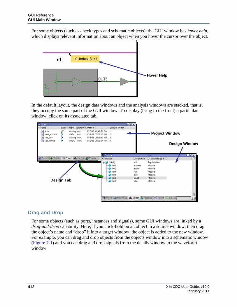
0-In CDC User Guide, v10.0412
GUI ReferenceGUI Main Window
February 2011
For some objects (such as check types and schematic objects), the GUI window has hover help,which displays relevant information about an object when you hover the cursor over the object.
In the default layout, the design data windows and the analysis windows are stacked, that is,they occupy the same part of the GUI window. To display (bring to the front) a particularwindow, click on its associated tab.
Drag and Drop
For some objects (such as ports, instances and signals), some GUI windows are linked by adrag-and-drop capability. Here, if you click-hold on an object in a source window, then dragthe object’s name and “drop” it into a target window, the object is added to the new window.For example, you can drag and drop objects from the objects window into a schematic window(Figure 7-1) and you can drag and drop signals from the details window to the waveformwindow
Hover Help
u1.txdata3_r1
Project Window
Design Window
Design Tab
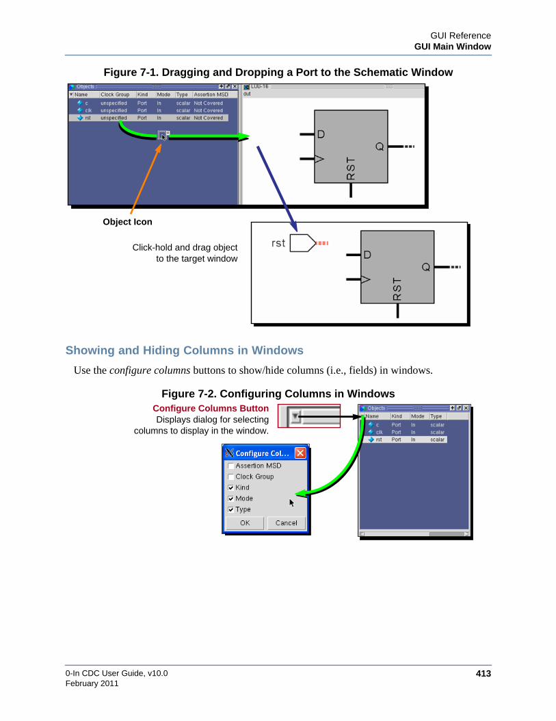
GUI ReferenceGUI Main Window
0-In CDC User Guide, v10.0 413February 2011
Figure 7-1. Dragging and Dropping a Port to the Schematic Window
Showing and Hiding Columns in Windows
Use the configure columns buttons to show/hide columns (i.e., fields) in windows.
Figure 7-2. Configuring Columns in Windows
Object Icon
Click-hold and drag objectto the target window
Configure Columns ButtonDisplays dialog for selecting
columns to display in the window.

0-In CDC User Guide, v10.0414
GUI ReferenceGUI Main Window
February 2011
Showing and Closing Windows
Use the View menu to show and close a window. Use the close button (x) at the top right of awindow to close that window.
Changing the Help Browser
Mozilla is the default help browser, but you can set a different browser for online help. Tochange the help browser for the GUI: Tools >Edit Preferences. Select the By Name tab. Set upthe browserExec/browserCommand data: browserExec is the path to the browser executable;browserCommand is the command passed to the browser executable. For example:
browserExec: /usr/bin/firefox
browserCommand: -browser -height 500 -width 600 <URL>
<URL> is a literal. It is used to pass the URL of the target document to the browser. Forexample, the invocation of the Firefox browser has URL as an option. For Mozilla, the option isopenfile(URL), so its Command value is:
openfile(<URL>).
Depending on your selected browser, you might need to adjust some browser preferences. Fromthe title page of an HTML document, scroll down and click on the Browser Requirements link.Select the Browser Settings topic and follow the directions for your brand of browser.
With the Firefox browser, if the fonts are too small, you can adjust the font sizes from thebrowser itself (for example, using [CTRL SHIFT +] and [CTRL –]).
View Menu ✔ Indicates the pane is displayed close Button (X)Closes the window

GUI ReferenceGUI Main Window
0-In CDC User Guide, v10.0 415February 2011
Window LayoutsAdjust the current window layout using the move-window buttons to drag windows to newlocations and the stretch-shrink bars to adjust the sizes of the windows (Figure 7-3).
Figure 7-3. Organizing the Window Layout
Zoom/Unzoom Buttons
When the window shows multiple windows, each window has a zoom button (+) at the top rightof the window. A zoomed window takes up the entire layout (Figure 7-4). The other windowsare available from tabs at the bottom of the window. When you select a tab, its window isdisplayed as a zoomed window. The unzoom button (–) on the zoomed window returns thewindow to the composite window layout.
Window
Click-hold and drag window outline tothe new location for the window.
Stretch/Shrink BarClick-hold and drag
reshape the window
Outline
window border to
Move-Window Button

0-In CDC User Guide, v10.0416
GUI ReferenceGUI Main Window
February 2011
Figure 7-4. Zoomed View of a Window
Undock/Dock Buttons
The undock button at the top right of a window undocks the window, so it appears as a separatewindow (Figure 7-5). You also can undock a window by using its move-window button to dragthe window to the edge of the main window. The dock button on an undocked window docksthe window back into the main window.
Figure 7-5. Undocking a Window
Returns the windowto the previous layout
Tabs for the
Unzoom Button
other panes
On a layout showsthe zoomed view
Zoom Button
view of the window
Moves the windowto its own window
Undock Button
Re-docks the window
Dock Button
back to the main window
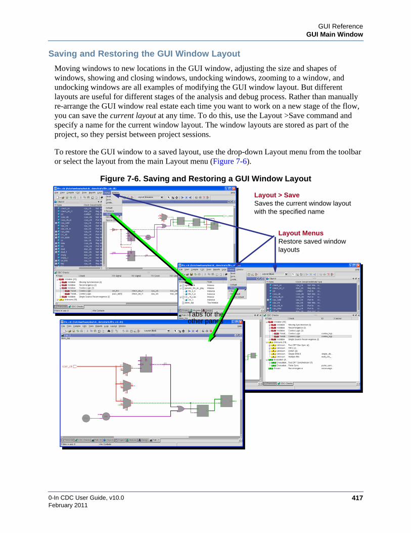
GUI ReferenceGUI Main Window
0-In CDC User Guide, v10.0 417February 2011
Saving and Restoring the GUI Window Layout
Moving windows to new locations in the GUI window, adjusting the size and shapes ofwindows, showing and closing windows, undocking windows, zooming to a window, andundocking windows are all examples of modifying the GUI window layout. But differentlayouts are useful for different stages of the analysis and debug process. Rather than manuallyre-arrange the GUI window real estate each time you want to work on a new stage of the flow,you can save the current layout at any time. To do this, use the Layout >Save command andspecify a name for the current window layout. The window layouts are stored as part of theproject, so they persist between project sessions.
To restore the GUI window to a saved layout, use the drop-down Layout menu from the toolbaror select the layout from the main Layout menu (Figure 7-6).
Figure 7-6. Saving and Restoring a GUI Window Layout
Layout Menus
Tabs for theother panes
Saves the current window layoutwith the specified name
Layout > Save
Restore saved windowlayouts

0-In CDC User Guide, v10.0418
GUI ReferenceAnalysis Windows
February 2011
Analysis WindowsThe CDC GUI has the following windows that show information about CDC analysis results.
• Errors/Warnings Window — shows errors and warnings reported by CDC analysis.
• CDC Checks Viewer — shows the static CDC analysis results and the merged results offormal verification and simulation with promoted CDC assertions.
Errors/Warnings WindowThe error/warnings window (Figure 7-7) shows the errors and warning generated by the formalsession.
Figure 7-7. Errors/Warnings Window
Hover the cursor over a message to display additional information about the error/warning.Right-click on a message to pop up a menu that you can use to:
• Import Log — loads information from a log file.
• Go to Source — in the associated log file document in a source browser.
• Go to Log File — in the detailed log file document in a source browser.
• Find — displays the find panel.

GUI ReferenceAnalysis Windows
0-In CDC User Guide, v10.0 419February 2011
Figure 7-8. Error/Warning Hover Help
CDC Checks ViewerThe CDC checks viewer (Figure 7-9) shows the static CDC analysis results and the mergedresults of formal verification and simulation with promoted CDC assertions. Entries in the CDCchecks tab are instances of CDC checks (schemes) detected by CDC static analysis. Selecting acheck shows detailed information in the details pane. Hovering over a selected group or CDCscheme entry shows bubble help with additional information about the selected object.
The Static field of a scheme is the scheme’s status reported by static CDC analysis. If a Provedatabase is merged, a Prove field shows the formal analysis results for the associated protocolcheck. If a database generated by simulation with the promoted protocol checkers is merged, aSimulation field shows the simulation results. The Type field shows the merged results form allthese analyses. See “Status Flags” on page 53 for an explanation of the status flags used to showthe status of these field entries.
Hover HelpHovering cursor over error messagedisplays bubble help message with
added information
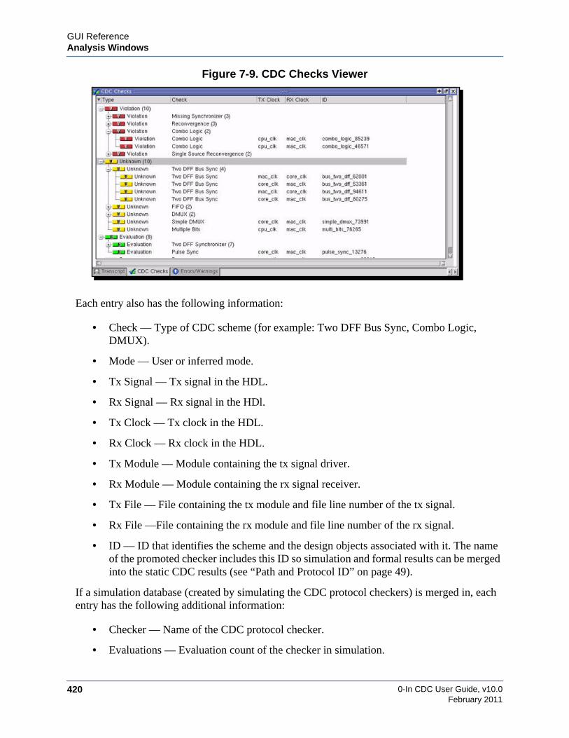
0-In CDC User Guide, v10.0420
GUI ReferenceAnalysis Windows
February 2011
Figure 7-9. CDC Checks Viewer
Each entry also has the following information:
• Check — Type of CDC scheme (for example: Two DFF Bus Sync, Combo Logic,DMUX).
• Mode — User or inferred mode.
• Tx Signal — Tx signal in the HDL.
• Rx Signal — Rx signal in the HDl.
• Tx Clock — Tx clock in the HDL.
• Rx Clock — Rx clock in the HDL.
• Tx Module — Module containing the tx signal driver.
• Rx Module — Module containing the rx signal receiver.
• Tx File — File containing the tx module and file line number of the tx signal.
• Rx File —File containing the rx module and file line number of the rx signal.
• ID — ID that identifies the scheme and the design objects associated with it. The nameof the promoted checker includes this ID so simulation and formal results can be mergedinto the static CDC results (see “Path and Protocol ID” on page 49).
If a simulation database (created by simulating the CDC protocol checkers) is merged in, eachentry has the following additional information:
• Checker — Name of the CDC protocol checker.
• Evaluations — Evaluation count of the checker in simulation.
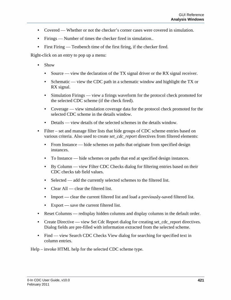
GUI ReferenceAnalysis Windows
0-In CDC User Guide, v10.0 421February 2011
• Covered — Whether or not the checker’s corner cases were covered in simulation.
• Firings — Number of times the checker fired in simulation..
• First Firing — Testbench time of the first firing, if the checker fired.
Right-click on an entry to pop up a menu:
• Show
• Source — view the declaration of the TX signal driver or the RX signal receiver.
• Schematic — view the CDC path in a schematic window and highlight the TX orRX signal.
• Simulation Firings — view a firings waveform for the protocol check promoted forthe selected CDC scheme (if the check fired).
• Coverage — view simulation coverage data for the protocol check promoted for theselected CDC scheme in the details window.
• Details — view details of the selected schemes in the details window.
• Filter – set and manage filter lists that hide groups of CDC scheme entries based onvarious criteria. Also used to create set_cdc_report directives from filtered elements:
• From Instance — hide schemes on paths that originate from specified designinstances.
• To Instance — hide schemes on paths that end at specified design instances.
• By Column — view Filter CDC Checks dialog for filtering entries based on theirCDC checks tab field values.
• Selected — add the currently selected schemes to the filtered list.
• Clear All — clear the filtered list.
• Import — clear the current filtered list and load a previously-saved filtered list.
• Export — save the current filtered list.
• Reset Columns — redisplay hidden columns and display columns in the default order.
• Create Directive — view Set Cdc Report dialog for creating set_cdc_report directives.Dialog fields are pre-filled with information extracted from the selected scheme.
• Find — view Search CDC Checks View dialog for searching for specified text incolumn entries.
Help – invoke HTML help for the selected CDC scheme type.

0-In CDC User Guide, v10.0422
GUI ReferenceDebug Windows
February 2011
Debug WindowsThe CDC GUI has the following tools used to debug problems detected by CDC analysis:
• Details Window — shows details for the design instances/entities.
• Objects Window — design objects (ports and internal registers/nets) for design units.
• Log/Report Browsers — shows logs and reports.
• Schematics Viewer — shows schematics for the design.
• Source Code Editor — displays and edits source code..
• Waveform Viewer — shows waveforms for assertion firings, sanity checks, anystatechecks and cover points.
The debug windows are not all stacked together like the design data windows and the analysiswindows. The firings, objects, details and FSM viewer windows are singular windows. Onlyone of each can be displayed and the contents are updated depending on your selections in theanalysis windows. The source code editor, schematic browser and waveform viewer aremultiple windows. You can display multiple instances of each of these windows. Each of thesethree groups of windows are stacked. For example, you can display waveforms for severalproperty violations at the same time. The waveform windows are stacked together. Clicking ona tab displays its associated waveform viewer in front.
Details WindowThe details window (Figure 7-10) shows the details for the design instance or entity selected inthe design window.
Figure 7-10. Details Window
The window shows the following information:
• Name —instance/entity name.
• Inst Type — type of instance (for example, Module Instance).
• Module — name of the model (module/architecture) for the instance.

GUI ReferenceDebug Windows
0-In CDC User Guide, v10.0 423February 2011
• Clock Group — clock group that clocks the instance, or unspecified.
• Assertion MSD — ratio of the instance’s registers covered by assertions (within theMinimum Sequential Distance).
Objects WindowThe objects window (Figure 7-11) displays design objects (ports and internal registers/nets) forthe current design unit instance . Click on a design unit instance in the design window to selectthe current design unit.
Figure 7-11. Objects Window
Use drag-and-drop to add selected objects to the waveform viewer or the schematics viewer.Right-click on an entry to pop up a menu that you can use to:
• Go to Declaration — in the source file in a source code editor.
• Edit Directive
• Set Signal —see “set_cdc_signal” on page 299.
• Set Reset —see “set_reset” on page 312.
• Set Constant —see “set_constant” on page 305.
• Set Port Domain —see “set_cdc_port_domain” on page 276.
• Set Clock —see “set_cdc_clock” on page 263.
• Show in Schematic
• New View — open a new schematic viewer showing the selected objects.
• Active View — add the selected objects to the active schematic view.

0-In CDC User Guide, v10.0424
GUI ReferenceDebug Windows
February 2011
• Abstract View — show the selected objects in an abstract view of the design unit.
• Select in Schematic —selects and highlights the selected objects in the active schematicview.
• Add to Path Tracing
• From Signals — Add the selected objects to the From Signals group for path tracing.
• To Signals — Add the selected objects to the To Signals group for path tracing.
• Thru Signals — Add the selected objects to the Thru Signals group for path tracing.
• Add to Wave Window
• Current — add the selected objects to the current waveform view.
• Always — always add the selected objects to new waveform views.
Log/Report BrowsersYou can open a log or report directly in a browser (Figure 7-12):
• File > Open or in the toolbar.
• Log menu — to view a particular log file.
• Report menu — to view a particular report.
Figure 7-12. Log/Report Browser
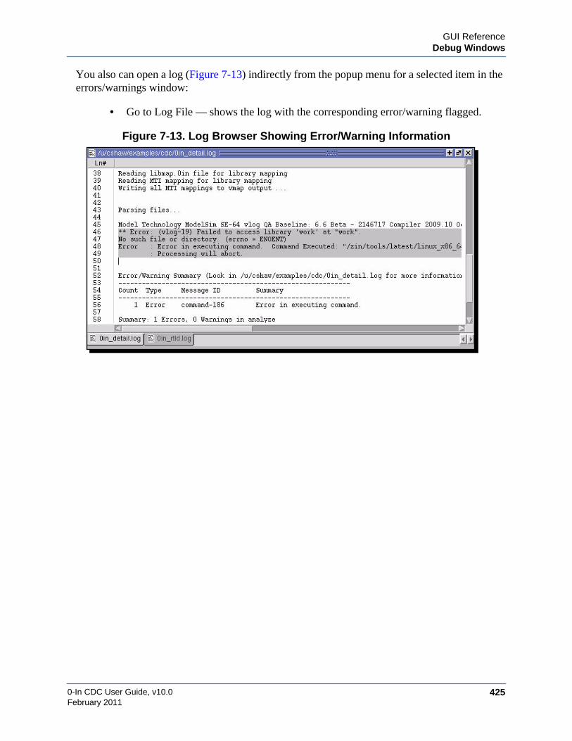
GUI ReferenceDebug Windows
0-In CDC User Guide, v10.0 425February 2011
You also can open a log (Figure 7-13) indirectly from the popup menu for a selected item in theerrors/warnings window:
• Go to Log File — shows the log with the corresponding error/warning flagged.
Figure 7-13. Log Browser Showing Error/Warning Information

0-In CDC User Guide, v10.0426
GUI ReferenceSchematics Viewer
February 2011
Schematics ViewerRunning a Show >Schematic command for a CDC check or a Show in Schematic command fora clock in the Clocks window displays a schematic view of the clock domain crossing schemeor the drivers/receivers of the selected clock (Figure 7-14).
Figure 7-14. Schematics Viewer
Expanding Logic in the Schematic ViewThe Show >Fanin popup command for a property (in the Properties tab) displays thecollapsed schematic view of the property. You can expand the view to show details ofthe fanin logic driving the property. You can:

GUI ReferenceSchematics Viewer
0-In CDC User Guide, v10.0 427February 2011
• Expand the view to show the drivers/readers of a net or port. To do this, double-clickon the net or port.
• Expand the view to show details of combinational logic. To do this, double-click onthe combo logic block.
double-clickon net/port
expand drivers/readersof a net or port
double-clickon logic
expandcombinational logic
block
TBS
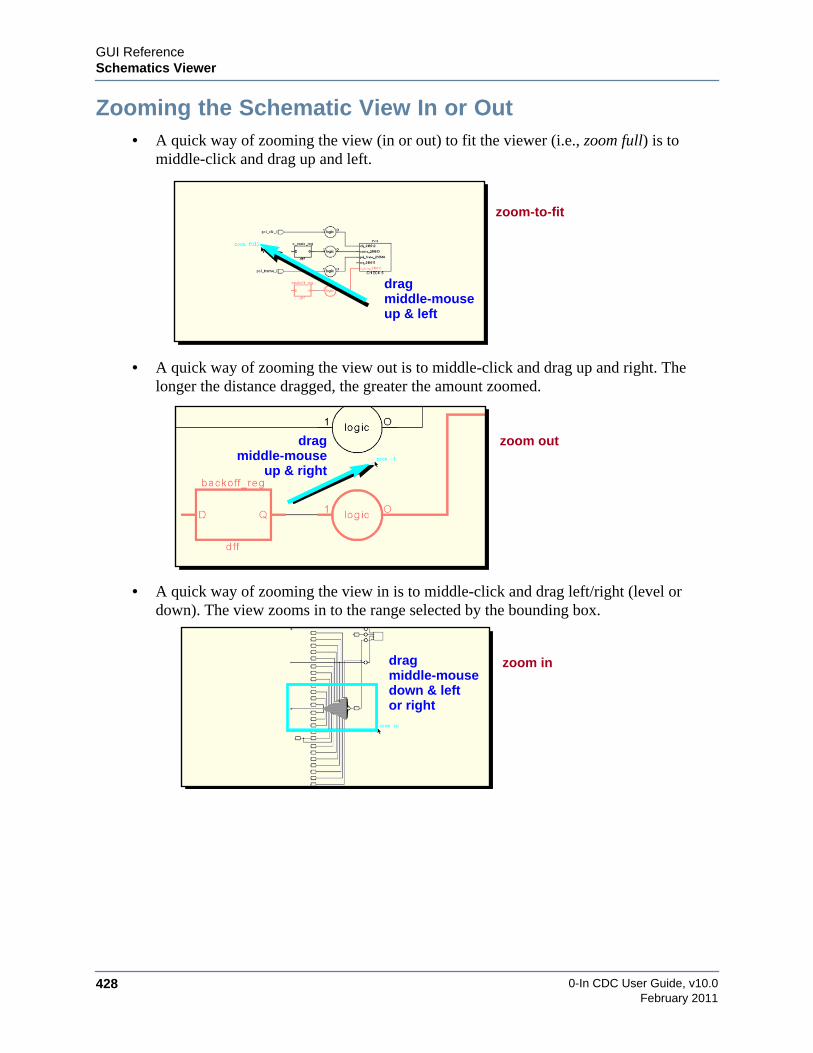
0-In CDC User Guide, v10.0428
GUI ReferenceSchematics Viewer
February 2011
Zooming the Schematic View In or Out• A quick way of zooming the view (in or out) to fit the viewer (i.e., zoom full) is to
middle-click and drag up and left.
• A quick way of zooming the view out is to middle-click and drag up and right. Thelonger the distance dragged, the greater the amount zoomed.
• A quick way of zooming the view in is to middle-click and drag left/right (level ordown). The view zooms in to the range selected by the bounding box.
drag
up & leftmiddle-mouse
zoom-to-fit
drag
up & rightmiddle-mouse
zoom out
drag
down & leftmiddle-mouse
zoom in
or right
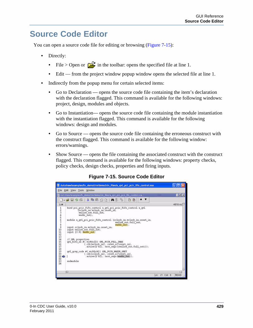
GUI ReferenceSource Code Editor
0-In CDC User Guide, v10.0 429February 2011
Source Code EditorYou can open a source code file for editing or browsing (Figure 7-15):
• Directly:
• File > Open or in the toolbar: opens the specified file at line 1.
• Edit — from the project window popup window opens the selected file at line 1.
• Indirectly from the popup menu for certain selected items:
• Go to Declaration — opens the source code file containing the item’s declarationwith the declaration flagged. This command is available for the following windows:project, design, modules and objects.
• Go to Instantiation— opens the source code file containing the module instantiationwith the instantiation flagged. This command is available for the followingwindows: design and modules.
• Go to Source — opens the source code file containing the erroneous construct withthe construct flagged. This command is available for the following window:errors/warnings.
• Show Source — opens the file containing the associated construct with the constructflagged. This command is available for the following windows: property checks,policy checks, design checks, properties and firing inputs.
Figure 7-15. Source Code Editor
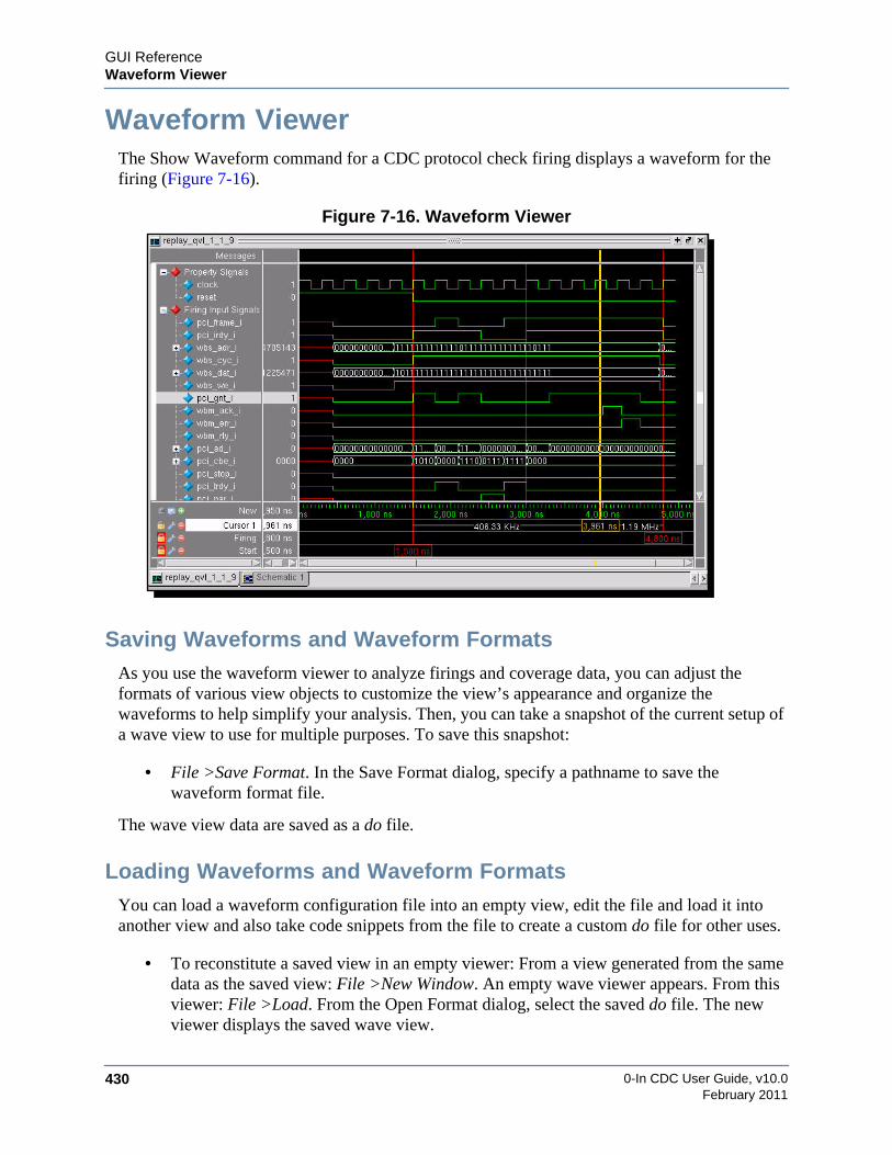
0-In CDC User Guide, v10.0430
GUI ReferenceWaveform Viewer
February 2011
Waveform ViewerThe Show Waveform command for a CDC protocol check firing displays a waveform for thefiring (Figure 7-16).
Figure 7-16. Waveform Viewer
Saving Waveforms and Waveform FormatsAs you use the waveform viewer to analyze firings and coverage data, you can adjust theformats of various view objects to customize the view’s appearance and organize thewaveforms to help simplify your analysis. Then, you can take a snapshot of the current setup ofa wave view to use for multiple purposes. To save this snapshot:
• File >Save Format. In the Save Format dialog, specify a pathname to save thewaveform format file.
The wave view data are saved as a do file.
Loading Waveforms and Waveform FormatsYou can load a waveform configuration file into an empty view, edit the file and load it intoanother view and also take code snippets from the file to create a custom do file for other uses.
• To reconstitute a saved view in an empty viewer: From a view generated from the samedata as the saved view: File >New Window. An empty wave viewer appears. From thisviewer: File >Load. From the Open Format dialog, select the saved do file. The newviewer displays the saved wave view.

GUI ReferenceWaveform Viewer
0-In CDC User Guide, v10.0 431February 2011
• To load saved wave format data into the current wave view: Create a do file with thedesired wave format data (taken from a saved waveform format file), for example:
WaveRestoreCursors {{Config Complete} {1033 ns} 1}configure wave -justifyvalue rightconfigure wave -timelineunits psbookmark add wave {Cmd Load} {{1774 ns} {3709 ns}} 0bookmark add wave Firing {{893 ns} {4887 ns}} 0
From the current wave view: File >Load. From the Open Format dialog, select the dofile.
• To load saved wave format data into the every wave view: Create a do file with thedesired wave format data (taken from a saved waveform format file), for example:
add wave -noupdate -format Logic -radix binary replay_qvl_.../clock1add wave -noupdate -format Logic replay_qvl_.../pci_err__inadd wave -noupdate -format Logic -radix binary replay_qvl.../comboWaveRestoreCursors {{Config Complete} {1033 ns} 1}configure wave -justifyvalue rightconfigure wave -timelineunits psbookmark add wave {Cmd Load} {{1774 ns} {3709 ns}} 0bookmark add wave Firing {{893 ns} {4887 ns}} 0
From the GUI main window: Tools >Edit Preferences. From the Edit Preferencesdialog, go to the Misc tab. In the Waveform section, add the do file to the ConfigurationFile field.
This procedure applies the saved wave view formatting to every waveform. The identityof the wave format configuration file is saved in .0in_ui_local_prefs, so it is persistentacross GUI sessions run from the current directory. You also can use this procedure toautomatically load a reference set of specific signals to every waveform. Thesesignals provide a baseline for analyzing formal results. If the added signals are in thefanin/fanout cones of the current property, formal analysis controls affect theirindividual waveforms and the baseline information is useful. Signals not in these conesprovide baseline information up to the starting state for formal analysis, but are set toflat-line after that.
Zooming the Wave View In or Out• Use the zoom in, zoom out, zoom full and zoom in on active cursor icons
( ).

0-In CDC User Guide, v10.0432
GUI ReferenceWaveform Viewer
February 2011
• A quick way of zooming the view (in or out) to fit the viewer (i.e., zoom full) is tomiddle-click and drag up and left.
• A quick way of zooming the view out is to middle-click and drag up and right. Thelonger the distance dragged, the greater the amount zoomed.
• A quick way of zooming the view in is to middle-click and drag left/right (level ordown). The view zooms in to the range selected by the starting and ending points.
Capturing Zoomed/Scrolled Views as BookmarksAs you analyze a waveform, you zoom the view in and out, scroll the waves back and forth intime and scroll up and down lists of signals. Often you want to “capture” specific views, so youcan quickly jump the view to them. Such a captured view is called a bookmark. You can:
• Create a bookmark for the current view: Add >Bookmark. In the Bookmark Propertiesdialog, provide a mnemonic for the view in the Bookmark Name field. By default, thebookmark saves the zoom value (Zoom Range) and the vertical scroll location (TopIndex). You can select to save either or both with the bookmark.
• Jump the viewer to a saved bookmark view: View >Bookmarks >name. The Bookmarkssubmenu lists all the saved bookmarks. Here, name is ne of the bookmarks.
drag
up & leftmiddle-mouse
zoom-to-fit
zoom outdrag
up & rightmiddle-mouse
zoom indrag
down & leftmiddle-mouse
or right

GUI ReferenceWaveform Viewer
0-In CDC User Guide, v10.0 433February 2011
• Manage bookmarks: View >Bookmarks >Bookmarks. Use the Bookmark Selectiondialog to Add, Modify, Delete and Goto individual bookmarks.
Selecting Multiple Signals for Format OperationsSome format operations—such as setting the signal value radix and combining signals intosignal groups—can be applied to multiple signals at a time. When you click on a signal, it isselected (but other selections are deselected). To select multiple signals:
• Use SHIFT-click to select a range of adjacent signals.
• Use CTRL-click to add individual signals to the current selection.
Changing the Display Properties of SignalsDouble-click on the signal name. The Wave Properties dialog for the signal is displayed. Youcan:
• Give the signal a Display Name, which is shown in the pathname pane in place of thesignal name.
• Select colors for the signal waveform (Wave Color) and signal name (Name Color).
• Change the Radix (for example, decimal, octal, hex, binary) for the displayed signalvalue.
To change display properties for multiple signals, select the signals and use the Format menucommands (Radix, RadixEnum, Format, Color and Height) to adjust their display properties asa group.
Changing the Signal Pathname PropertiesSignal names are shown in the grey signal pathname pane at the left of the waveform viewer.You can toggle between short signal names and full pathnames.
• Click on the toggle leaf/full names icon ( ) at the top left of the cursor pane.
toggle
edit grid/timeline
leaf names full names

0-In CDC User Guide, v10.0434
GUI ReferenceWaveform Viewer
February 2011
• Since full signal names can be overly long, you can set the maximum number ofhierarchical levels displayed in the long names. To do this: click the edit grid/timelineicon ( ) next to the pathname toggle icon. From the Display tab of the Wave WindowProperties dialog, set the Display Signal Path field to the maximum number of pathnameelements to display.
Adding SignalsTo add signals, do one of the following:
• From the signals pane popup menu, run Add Signals >Current View. In the Add Signalto Wave Window dialog, select the signals and click on Add.
• From the objects window, select an object to add to the waveform. Drag and drop theobject to the signals pane of the waveform viewer.
Objects WindowWaveform View
drag and drop

GUI ReferenceWaveform Viewer
0-In CDC User Guide, v10.0 435February 2011
These signals are added to the current wave view. You also can identify signals to add to everywave view. To do this:
• From the signals pane popup menu, run Add Signals >Always. In the Always AddSignals to Wave Display dialog, update the Always Add These Signals list.
Removing SignalsTo remove signals from the viewer: select the signals and press Delete.
Organizing SignalsThe signals panel at the left of the waveform viewer lists the signals in the waveform. Signalsare identified by blue diamonds ( ). To organize the signals in the signals panel you can:
• Combine signals into a bus. To do this: select the signals for the bus and run Tools>Wave >Combine Signals. From the Combine Selected Signals dialog, provide a namefor the new bus. Set the other fields to determine the ordering of the signals in the bus.To remove the old signals after the bus is created, select Remove selected signals aftercombining. The created bus is identified by a red diamond ( ). The bus’ waveformshows the the combined values of the constitute signals.
• Combine signals into a wave group. To do this: select the signals for the group and runTools >Groups. From the Wave Group Create dialog, provide a name for the new wavegroup. The created group is identified by a red diamond ( ). No waveform is displayedfor the group itself, but waveforms for the group members are displayed when the groupis expanded.

0-In CDC User Guide, v10.0436
GUI ReferenceWaveform Viewer
February 2011
• Add category dividers. Signals in the signals panel are separated into categorieslabeled with dividers. When you add signals they are automatically assigned to theAdded Signals category (unless they are added by dragging and dropping).
To help you organize signals, you can add new category dividers. To do this, select thesignals and run View >Wave >Add >Divider. The Wave Divider Properties dialog isdisplayed. Specify a divider name and specify the divider height (to add extra spacingaround the divider).
To move a divider to a new location, select the divider and drag. To delete a divider,select the divider and press Delete.
• Re-order signals. Select the signals and drag to the new location. You also can sort thesignals alphabetically with the View >Wave >Sort commands (Ascending, Descending,Ascending Full Path and Descending Full Path). Signals are sorted within each category(defined by the dividers).
Using Multiple Window PanesInitially, the wave view has a single window pane showing the signals and waveforms. Thewave view has one scroll bar. So for large numbers of signals, you scroll back and forth tovisualize comparisons. To solve this problem, you can add one or more window panes. To dothis, run Add >Window Pane. A new empty window pane with a scroll bar is added just abovethe cursor region. Then, you can drag and drop (or copy and paste) signals from the originalpane to the added pane.
customcategorydividers

GUI ReferenceWaveform Viewer
0-In CDC User Guide, v10.0 437February 2011
Click and drag the pane boundary to reshape both panes. To delete a pane, click in the pane (theactive pane is identified with a white bar) and run Edit >Delete Window Pane.
Using Cursors to Analyze Events
The initial waveform shows at least three cursors. These are vertical lines that let you comparesignal behavior at specific times.
• Start indicates the starting state of formal analysis.
• Firing indicates a firing of the associated assertion or sanity check. For a cover propertyor covered checker, the Firing cursor indicates when the property became covered.
• A user-defined cursor is also displayed.
The left (gray) panel of the cursor pane lists the cursors. You can:
• Lock/unlock a cursor by clicking on the corresponding lock icon ( ). A locked cursorcannot move and is shown in red. The Start and Firing cursors are initially locked andshould be left locked. You can slide an unlocked cursor back and forth in time. Thecursor time is shown at the bottom of the cursor and also in the left panel. To set a cursorat a precise time (for example, if you have trouble adjusting the cursor), click on thecorresponding cursor tool ( ). Type the exact time in the Cursor Properties dialog.
• Give the cursor a name by selecting and right-clicking on the cursor name and entering auser-specified name.
• Add a new cursor by clicking on the add cursor icon ( ).
• Remove a cursor by selecting the cursor and clicking on the corresponding removecursor icon ( ).
original pane
added pane
separatescrollbars
drag and dropsignals to thenew pane
paneboundary
activepane
bar

0-In CDC User Guide, v10.0438
GUI ReferenceWaveform Viewer
February 2011
Capturing a Waveform’s ImageUndock and size the waveform viewer. From the undocked waveform viewer:
• To save the image as a BMP file, File >Export >Image. Use the Save Image dialog tosave the file.
• To save the image as a PostScript file, File >Print PostScript. Use the Write PostScriptdialog to print all or part of the waveform to a PS file.
Do not remove the focus from the waveform window until the capture completes (to preventthe captured image from being corrupted).
Adding a Source Code Variable to a WaveformYou can add a source code variable as a signal in a waveform view in two ways:
• Select the variable. All references to the variable are then highlighted. Drag and dropany reference to the variable to any wave view at the desired location.
• Select the variable. All references to the variable are then highlighted. Place the cursorover one of the variable’s references and run the Add to Wave Window popup command.The signal is added to the Added Signals category of the last displayed wave view.Drag the signal to the intended category and location.
Annotating Source Code with Variables’ ValuesYou can turn on source code annotation in either of two ways:
drag and drop
add a signal to a wave viewfrom the source code viewer
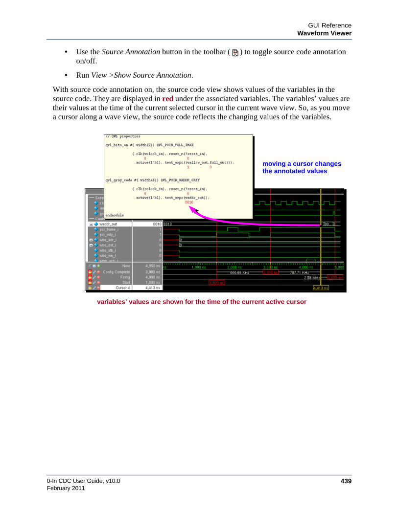
GUI ReferenceWaveform Viewer
0-In CDC User Guide, v10.0 439February 2011
• Use the Source Annotation button in the toolbar ( ) to toggle source code annotationon/off.
• Run View >Show Source Annotation.
With source code annotation on, the source code view shows values of the variables in thesource code. They are displayed in red under the associated variables. The variables’ values aretheir values at the time of the current selected cursor in the current wave view. So, as you movea cursor along a wave view, the source code reflects the changing values of the variables.
moving a cursor changes
variables’ values are shown for the time of the current active cursor
the annotated values

0-In CDC User Guide, v10.0440
GUI ReferenceProject Mode Windows
February 2011
Project Mode WindowsThe CDC GUI has the following windows that show information about CDC projects.
• Project Window — manages the source code files for the project.
• Design Window — shows the hierarchy of the DUT instances.
• Modules Window — shows the DUT design units.
• Clocks Window — shows the DUT clock signals.
• Directives Window — shows the current global directives.
The project mode windows display objects at the design unit level, set global directives for theobjects, manage source files for the project and set basic project properties. In addition, somewindows have a find panel (Figure 7-17). Use this panel to search for matches to specified textin the window
Figure 7-17. Find Panel in Design Data Windows
Project WindowThe project window (Figure 7-18) manages the source code files for the project.
Figure 7-18. Project Window
Pull-down MenuSearch direction
Find all matchesMatch whole word
Wrap search
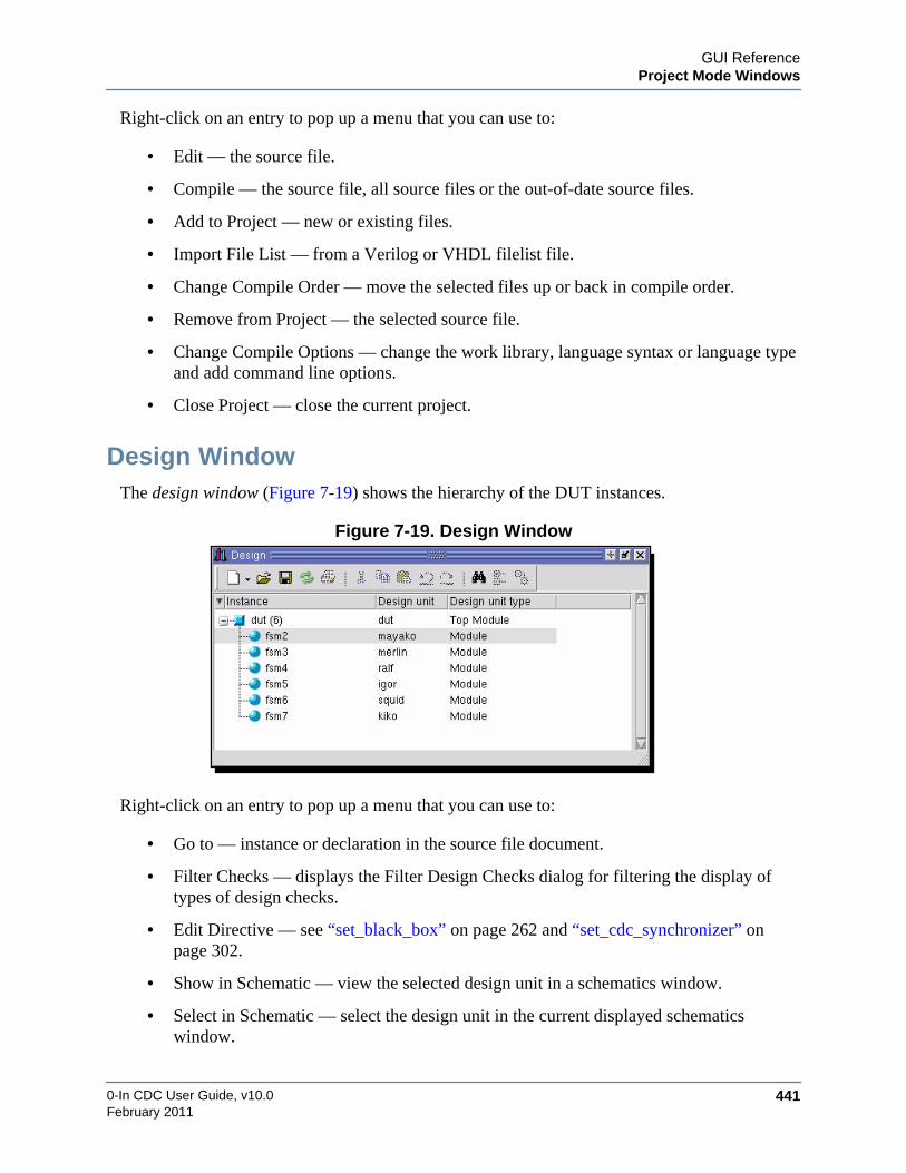
GUI ReferenceProject Mode Windows
0-In CDC User Guide, v10.0 441February 2011
Right-click on an entry to pop up a menu that you can use to:
• Edit — the source file.
• Compile — the source file, all source files or the out-of-date source files.
• Add to Project — new or existing files.
• Import File List — from a Verilog or VHDL filelist file.
• Change Compile Order — move the selected files up or back in compile order.
• Remove from Project — the selected source file.
• Change Compile Options — change the work library, language syntax or language typeand add command line options.
• Close Project — close the current project.
Design WindowThe design window (Figure 7-19) shows the hierarchy of the DUT instances.
Figure 7-19. Design Window
Right-click on an entry to pop up a menu that you can use to:
• Go to — instance or declaration in the source file document.
• Filter Checks — displays the Filter Design Checks dialog for filtering the display oftypes of design checks.
• Edit Directive — see “set_black_box” on page 262 and “set_cdc_synchronizer” onpage 302.
• Show in Schematic — view the selected design unit in a schematics window.
• Select in Schematic — select the design unit in the current displayed schematicswindow.

0-In CDC User Guide, v10.0442
GUI ReferenceProject Mode Windows
February 2011
• Search by Column — search for text pattern in design workspace.
• Copy to Clipboard — save the design unit name or details to the clipboard.
• Show Details — display a details window.
• Find — Displays the find panel.
Modules WindowThe modules window (Figure 7-20) shows the DUT design units with their assertion densities.
Figure 7-20. Modules Window
Right-click on an entry to pop up a menu that you can use to:
• Go to — declaration or instantiation in the source file.
• Edit Directive — see “set_black_box” on page 262 and “set_cdc_synchronizer” onpage 302..
• Show in Schematic — view the selected instance in a schematics window.
• Select in Schematic — select the instance in the current displayed schematics window.
• Copy to Clipboard — save the design unit name or details to the clipboard.
• Find — Displays the find panel.

GUI ReferenceProject Mode Windows
0-In CDC User Guide, v10.0 443February 2011
Clocks WindowThe clocks window (Figure 7-21) shows the DUT clock signals.
Figure 7-21. Clocks Window
Right-click on a clock to pop up a menu that you can use to:
• Go to — clock declaration in the source code or the design unit with the clock in thehierarchy.
• Edit Directive — see “set_cdc_clock” on page 263 and “set_constant” on page 305..
• Show in Schematic — shows the clock drivers, clock readers or both in a schematicsview.
• Select in Schematic — zooms in and selects the clock signal in the active schematicview.
• Add to Path Tracing — adds the clock to the path tracing points.\
• Copy to Clipboard — copies the clock path (name) or name and clock group (details) tothe clipboard.
• Show Details — shows the details window with clock name and clock group name.
• Find — Displays the find panel.

0-In CDC User Guide, v10.0444
GUI ReferenceProject Mode Windows
February 2011
Directives WindowThe directives tab (Figure 7-22) shows the current global directives. Use this tab to add and editglobal directives.
Figure 7-22. Directives Window
Right-click on an entry to pop up a menu that you can use to:
• Add — view a dialog customized for the selected type of directive. After completing theform, the directive is added to the directives tab. The directive types are: Clock(“set_cdc_clock” on page 263), Reset (“set_reset” on page 312), Port Domain(“set_cdc_port_domain” on page 276), Signal (“set_cdc_signal” on page 299), Report(“set_cdc_report” on page 293), Synchronizer (“set_cdc_synchronizer” on page 302),Constant (“set_constant” on page 305), Reconvergence (“set_cdc_reconvergence” onpage 291), Preference (“set_cdc_preference” on page 283), Blackbox (“set_black_box”on page 262), Memory (“set_memory” on page 308), FX Metastability(“set_cdc_fx_metastability_window” on page 269), FX Check (“set_cdc_fx_check” onpage 268) and FX Timescale (“set_cdc_fx_timescale” on page 270).
• Edit — view a dialog for changing the selected directive.
• Move — move the selected directives up or back in compile order.
• Delete — remove the selected directives.
• Import — load a set of directives from a text file.
• Export — save selected directives to a text (control) file.

0-In CDC User Guide, v10.0 445February 2011
Chapter 8Reports/Logs Reference
The CDC compiler automatically generates the following files:
• 0in.log – Short log file that is a copy of the standard output.
• 0in_cdc.db – CDC database for examining in the CDC GUI environment.
• 0in_cdc.rpt – Clock domain crossing report.
• 0in_cdc_setting.rpt – CDC settings report.
• 0in_cdc_ctrl.v – Clock domain crossing checker control file, which contains suggestedCDC protocol checker directives for signals crossing clock domains (for use withsimulation and the formal tools).
• 0in_cdc_design.rpt – CDC design report.
• 0in_cdc_mode_ctrl.v – Control file with directives specifying the modes inferred bymodal analysis (generated if the cdc -report_modes option is specified).
• 0in_cdc_param.inc – Checker parameter file.
• 0in_detail.log – Detailed log of the transcript.

0-In CDC User Guide, v10.0446
Reports/Logs ReferenceCDC Design Report
February 2011
CDC Design ReportThe clock domain crossing design report file (0in_cdc_design.rpt) shows detailed informationabout the clocks and clock groups in the design. It also shows summary information aboutdesign elements. The report contains the following:
• Clock Group Summary (see page 446)
• User-Specified Clock Groups (see page 447)
• Inferred Clock Groups (see page 447)
• Ignored Clock Groups (see page 449)
• General Design Information (see page 449)
• Detailed Design Information (see page 449)
• Port Domain Information (see page 450)
• Mode Information (see page 451)
Clock Group SummaryThe automatically generated 0in_cdc_design.rpt file contains the clock group summary thatdisplays the total counts for each type of clock group as shown in Example 8-1.
There are two types of clock groups: user-specified and inferred. All user-specified clocks aredefined by the user with the set_cdc_clock global directive. Inferred clock groups are clocksthat are not specified, but inferred by the CDC tool.
Example 8-1. Clock Group Summary
Clock Group Summary for ’top’=============================Total Number of Clock Groups : 5Number of User-Defined Clock Groups : 0Number of Inferred Clock Groups : 5Number of Ignored Clock Groups : 1
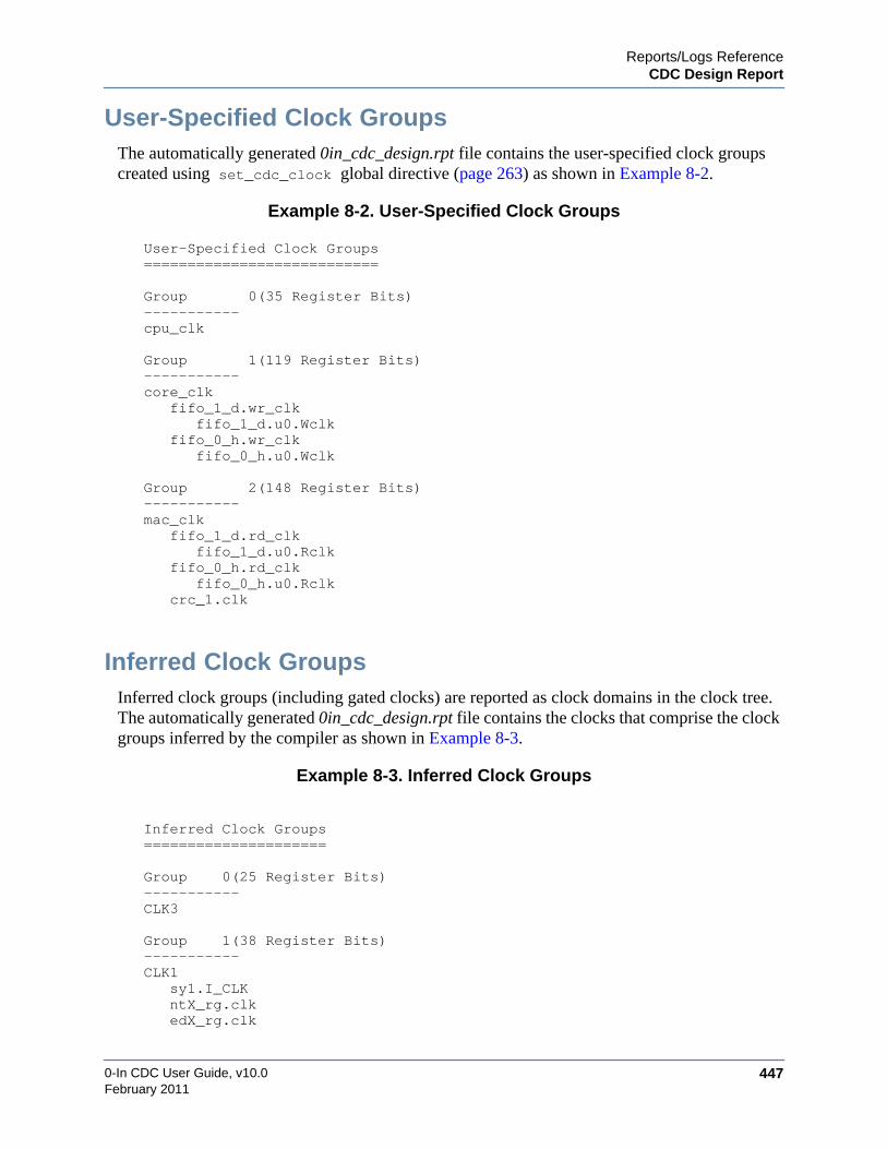
Reports/Logs ReferenceCDC Design Report
0-In CDC User Guide, v10.0 447February 2011
User-Specified Clock GroupsThe automatically generated 0in_cdc_design.rpt file contains the user-specified clock groupscreated using set_cdc_clock global directive (page 263) as shown in Example 8-2.
Example 8-2. User-Specified Clock Groups
User-Specified Clock Groups===========================
Group 0(35 Register Bits)-----------cpu_clk
Group 1(119 Register Bits)-----------core_clk
fifo_1_d.wr_clkfifo_1_d.u0.Wclk
fifo_0_h.wr_clkfifo_0_h.u0.Wclk
Group 2(148 Register Bits)-----------mac_clk
fifo_1_d.rd_clkfifo_1_d.u0.Rclk
fifo_0_h.rd_clkfifo_0_h.u0.Rclk
crc_1.clk
Inferred Clock GroupsInferred clock groups (including gated clocks) are reported as clock domains in the clock tree.The automatically generated 0in_cdc_design.rpt file contains the clocks that comprise the clockgroups inferred by the compiler as shown in Example 8-3.
Example 8-3. Inferred Clock Groups
Inferred Clock Groups=====================
Group 0(25 Register Bits)-----------CLK3
Group 1(38 Register Bits)-----------CLK1
sy1.I_CLKntX_rg.clkedX_rg.clk

0-In CDC User Guide, v10.0448
Reports/Logs ReferenceCDC Design Report
February 2011
tgX_rg.clkO1r_0_rg.clkO2r_0_rg.clkO2r_1_rg.clkO2r_2_rg.clkO2r_3_rg.clk
Group 2(12 Register Bits)-----------CLK2
sy2.I_CLKsy3.I_CLKsy4.I_CLKsy5.I_CLKdetrxst_0_rg.clk
Group 3(358 Register Bits)-----------CLKX [gate: ((TCS === 1’b0) ? CLK0 : ((TCS === 1’b1) ? TRK : 1’bx))]
O2w_0_rg.clkO2w_1_rg.clO2w_2_rg.clkO2w_3_rg.clksy6.I_CLKsy7.I_CLsy8.I_CLKsy9.I_CLKsya.I_CLKmodr.I_CLK
modr.modr1_0.I_CLKmodr.modr1_0.syb.I_CLKmodr.modr1_0.syc.I_CLK
. . .
modr.modr1_3.ft_rg.clkmodr.modr1_3.f_r_rg.clk
Group 4(5 Register Bits)-----------modr.rz0_tree [gate: (TCS ? TRK : ((I5[1:0] == 2'b0) ? RCLK[0] :RCLK[1]))]
modr.wz_rg.clkmodr.t_l0_rg.clk

Reports/Logs ReferenceCDC Design Report
0-In CDC User Guide, v10.0 449February 2011
Ignored Clock GroupsIgnored clock groups are identified by the set_cdc_clock -ignore global directive and are listedin the 0in_cdc_design.rpt file (Example 8-4).
Example 8-4. Ignored Clock Groups
Ignored Clock Groups====================
Group 0(158 Register Bits)-----------mac_clk [gate: (scan_mode ? scan_clk : mac_clk_in)] fifo_1_d.rd_clk fifo_1_d.u0.Rclk fifo_0_h.rd_clk fifo_0_h.u0.Rclk crc_1.clk
General Design InformationThe automatically generated 0in_cdc_design.rpt file contains the general design informationthat displays the total counts for each basic design element as shown in Example 8-5.
Example 8-5. General Design Information
General Design Information==========================Number of blackboxes = 0Number of Registers = 438Number of Latches = 0Number of RAMs = 0
Detailed Design InformationThe automatically generated 0in_cdc_design.rpt file contains the detailed design informationthat lists the basic design elements (except the registers) as shown in Example 8-6.
Example 8-6. Detailed Design Information
Detail Design Information=========================RAMs:-----
fifo_1_d.u0.datafifo_0_h.u0.data

0-In CDC User Guide, v10.0450
Reports/Logs ReferenceCDC Design Report
February 2011
Port Domain InformationThe automatically generated 0in_cdc_design.rpt file contains the port domain information thatdisplays the clock domains identified for the design’s ports as shown in Example 8-7.
Example 8-7. Port Domain Information
Printing port domain info=========================Port Direction Constraints Clock Domain Type---------------------------------------------------------------------RST input Reset { CLK3 CLK1 } 0-In CDCCLK3 input Clock { CLK3 } 0-In CDCCLK0 input ---CLK1 input Clock { CLK1 } 0-In CDCCLK2 input Clock ---RCLK input ---I1 input ---I2 input ---I3 input ---I4_0_I input ---I4_1_I input ---I4_2_I input ---I4_3_I input ---IT input { CLK3 } 0-In CDCI5 input { CLK2 CLK3 } 0-In CDCTM input ---TRK input ---TCS input ---O1 output { CLK1 } 0-In CDCO2_0 output { CLK1 } 0-In CDCO2_1 output { CLK1 } 0-In CDCO2_2 output { CLK1 } 0-In CDCO2_3 output { CLK1 } 0-In CDC
The following defines the port domain information:
• Port – Port name.
• Direction – The valid directions are: input, output, and inout
• Constraint – Identifies clock and reset ports.
• Clock Domain – Clock domain of the port. The {clock} indicates the primary clockfor the domain, and {clock1 | clock2 |...} indicates the clock domain isambiguous. The relevant primary clocks are listed. An async indicates the port ismarked as an asynchronous port using the set_cdc_port_domain global directive(page 276).
• Type – Method used to determine the clock domain. User indicates the clock domain isassigned by the set_cdc_clock global directive (page 263) or the port is markedasynchronous (using set_cdc_port_domain global directive (see page 276)). 0in_cdcindicates CDC analysis identified the domain (or potential domains).

Reports/Logs ReferenceCDC Design Report
0-In CDC User Guide, v10.0 451February 2011
Mode InformationThe automatically generated 0in_cdc_design.rpt file contains the mode information as shown inExample 8-8. Note that the mode information is generated only when the cdc -report_modes
option is specified.
Example 8-8. Mode Information
Mode information================---------------------------------------------Mode Type Information---------------------------------------------cdc_mode_0 0-In CDC Missing modecdc_mode_1 0-In CDC Missing modecdc_mode_2 0-In CDC Missing mode---------------------------------------------
User Modes==========
None
Inferred Modes==============
Constants in cdc_mode_0 (Missing)-----------------------------------------Signal Value-----------------------------------------TCS 1'b1-----------------------------------------
Constants in cdc_mode_1 (Missing)-----------------------------------------Signal Value-----------------------------------------TCS 1'b0I5[1:0] 2'b00-----------------------------------------
Constants in cdc_mode_2 (Missing)-----------------------------------------Signal Value-----------------------------------------TCS 1'b0I5[1:0] 2'b01-----------------------------------------

0-In CDC User Guide, v10.0452
Reports/Logs ReferenceClock Domain Crossing Report
February 2011
Clock Domain Crossing ReportThe automatically generated clock domain crossing report file (0in_cdc.rpt) shows detailedinformation about the CDC signals and their schemes. The report contains the following:
• CDC Summary (see page 452)
• CDC Promotion Summary (see page 453)
• Violations (see page 453)
• Cautions (see page 454)
• Evaluations (see page 455)
• Waived (see page 456)
• Proven (see page 456)
• Filtered (see page 457)
• Custom Synchronization Modules (see page 458)
• Asynchronous Reset Detection (see page 458)
• Asynchronous Reset Synchronizers Detected (see page 458)
• User-entered Asynchronous Reset (see page 459)
• Asynchronous Reset with Missing Synchronizer (see page 459)
• All Transmitting Signals (see page 461)
CDC SummaryThe automatically generated 0in_cdc.rpt file contains the CDC summary that shows the countsfor each type of violation, caution, and evaluation as shown in Example 8-9.
Example 8-9. CDC Summary
CDC Summary=================================================================Violations (7)-----------------------------------------------------------------Single-bit signal does not have proper synchronizer. (3)Combinational logic before synchronizer. (1)Reconvergence of synchronizers. (1)Single Source Reconvergence of synchronizers. (2)
Cautions (6)-----------------------------------------------------------------DMUX synchronization. (2)Multiple-bit signal across clock domain boundary. (1)FIFO synchronization. (2)

Reports/Logs ReferenceClock Domain Crossing Report
0-In CDC User Guide, v10.0 453February 2011
Handshake synchronization. (1)
Evaluations (1)-----------------------------------------------------------------Single-bit signal synchronized by DFF synchronizer. (1)
Waived (6)-----------------------------------------------------------------Multiple-bit signal synchronized by DFF synchronizer. (4)Reconvergence of synchronizers. (2)
Proven (8)-----------------------------------------------------------------Single-bit signal synchronized by DFF synchronizer. (6)Reconvergence of synchronizers. (1)Pulse Synchronization. (1)
Filtered (1)-----------------------------------------------------------------Combinational logic before synchronizer. (1)
CDC Promotion SummaryThe automatically generated 0in_cdc.rpt file contains the CDC promotion summary that showsthe checkers that are promoted and the checkers that are not promoted as shown inExample 8-10.
Example 8-10. CDC Promotion Summary
CDC Promotion Summary==========================================================Promoted protocol checkers (18)Unpromoted checkers (see 0in_detail.log) (6)==========================================================
ViolationsThe automatically generated 0in_cdc.rpt file contains the CDC violations that shows the pathsthat result in the CDC violations as shown in Example 8-11.
Example 8-11. Violations
Violations========================================================================Single-bit signal does not have proper synchronizer. (no_sync)------------------------------------------------------------------------cpu_clk_in : start : init_done (/demo_top.v : 82)
core_clk_in : end : tx_state[0] (/demo_top.v : 193) (ID:no_sync_47305)core_clk_in : end : tx_en (/demo_top.v : 86) (ID:no_sync_2628)core_clk_in : end : tx_mask_valid (/demo_top.v : 90) (ID:no_sync_31547)
Combinational logic before synchronizer. (combo_logic)-------------------------------------------------------------------------

0-In CDC User Guide, v10.0454
Reports/Logs ReferenceClock Domain Crossing Report
February 2011
cpu_clk_in : start : pass_en[1] (/demo_top.v : 79)mac_clk_in : end : check_en_r1 (/demo_top.v : 324) (ID:combo_logic_46571)
cpu_clk_in : start : err_thrs (/demo_top.v : 78)mac_clk_in : end : check_en_r1 (/demo_top.v : 324) (ID:combo_logic_85239)
Reconvergence of synchronizers. (reconvergence)-------------------------------------------------------------------------mac_clk_in : end : rx_payload_en (/demo_top.v : 381)
(ID:reconvergence_68819)mac_clk_in : start : tx_sop_r2 (/demo_top.v : 360)mac_clk_in : start : tx_eop_r2 (demo_top.v : 371)
mac_clk_in : end : rx_masked_data (/demo_top.v : 382) (ID:reconvergence_51498)
mac_clk_in : start : tx_eop_r2 (/demo_top.v : 371)mac_clk_in : start : tx_mask_valid_r2 (/demo_top.v : 303)
mac_clk_in : end : pass_valid (/demo_top.v : 47) (ID:reconvergence_31994)
mac_clk_in : start : fifo_1_d.wp_s (/generic_fifo_dc_gray.v : 149)mac_clk_in : start : fifo_0_h.wp_s (/generic_fifo_dc_gray.v : 149)
mac_clk_in : end : pass (/demo_top.v : 45) (ID:reconvergence_11498)mac_clk_in : start : fifo_1_d.wp_s (/generic_fifo_dc_gray.v : 149)mac_clk_in : start : fifo_0_h.wp_s (/generic_fifo_dc_gray.v : 149)
CautionsThe automatically generated 0in_cdc.rpt file contains the CDC cautions that displays the pathsthat result in the CDC cautions as shown in Example 8-12.
Example 8-12. Cautions
Cautions=======================================================================DMUX synchronization. (dmux)-----------------------------------------------------------------------cpu_clk_in : start : fstp[7:1] (/demo_top.v : 81)
mac_clk_in : end : crc_1.scramble (/demo_top.v : 435) (ID:dmux_30303)via : crc_1.fstp
core_clk_in : start : tx_mask_d (/demo_top.v : 198)mac_clk_in : end : mask (/demo_top.v : 336) (ID:dmux_12402)
Multiple-bit signal synchronized by DFF synchronizer. (bus_two_dff)-----------------------------------------------------------------------core_clk_in : start : fifo_1_d.wp_gray (/generic_fifo_dc_gray.v : 147)
mac_clk_in : end : fifo_1_d.wp_s1 (/generic_fifo_dc_gray.v : 150) (ID:bus_two_dff_80275)
mac_clk_in : start : fifo_1_d.rp_gray (/generic_fifo_dc_gray.v : 148)core_clk_in : end : fifo_1_d.rp_s1 (/generic_fifo_dc_gray.v : 150)
(ID:bus_two_dff_94611)

Reports/Logs ReferenceClock Domain Crossing Report
0-In CDC User Guide, v10.0 455February 2011
core_clk_in : start : fifo_0_h.wp_gray (/generic_fifo_dc_gray.v : 147)mac_clk_in : end : fifo_0_h.wp_s1 (/generic_fifo_dc_gray.v : 150)
(ID:bus_two_dff_53361)
mac_clk_in : start : fifo_0_h.rp_gray (/generic_fifo_dc_gray.v : 148)core_clk_in : end : fifo_0_h.rp_s1 (generic_fifo_dc_gray.v : 150)
(ID:bus_two_dff_62001)
Multiple-bit signal across clock domain boundary. (multi_bits)----------------------------------------------------------------------cpu_clk_in : start : crc_seed[7:1] (/demo_top.v : 80)
mac_clk_in : end : crc_1.crc_16 (/demo_top.v : 434) (ID:multi_bits_76265)
via : crc_1.seed
EvaluationsThe automatically generated 0in_cdc.rpt file contains the CDC evaluations that displays thepaths that result in the CDC evaluations as shown in Example 8-13.
Example 8-13. Evaluations
Evaluations=======================================================================Single-bit signal synchronized by DFF synchronizer. (two_dff)-----------------------------------------------------------------------cpu_clk_in : start : init_done (/demo_top.v : 82)
mac_clk_in : end : init_done_r1 (/demo_top.v : 119) (ID:two_dff_5840)
cpu_clk_in : start : pass_en[0] (/demo_top.v : 79)mac_clk_in : end : pass_en0_r1 (/demo_top.v : 314) (ID:two_dff_81824)
core_clk_in : start : tx_sop (/demo_top.v : 88)mac_clk_in : end : tx_sop_r1 (/demo_top.v : 360) (ID:two_dff_11314)
core_clk_in : start : tx_eop (/demo_top.v : 87)mac_clk_in : end : tx_eop_r1 (/demo_top.v : 371) (ID:two_dff_54238)
core_clk_in : start : tx_mask_valid (/demo_top.v : 90)mac_clk_in : end : tx_mask_valid_r1 (/demo_top.v : 303)
(ID:two_dff_52495)
Pulse Synchronization. (pulse_sync)-----------------------------------------------------------------------core_clk_in : start : tx_en (/demo_top.v : 86)
mac_clk_in : end : tx_en_r1 (/demo_top.v : 289) (ID:pulse_sync_13276)
Memory Synchronization. (memory_sync)-----------------------------------------------------------------------core_clk_in : start : fifo_1_d.u0.data (/dpmem2clk.v : 58)
mac_clk_in : end : fifo_1_d.u0.outport (/dpmem2clk.v : 60)(ID:memory_sync_1560)

0-In CDC User Guide, v10.0456
Reports/Logs ReferenceClock Domain Crossing Report
February 2011
core_clk_in : start : fifo_0_h.u0.data (/dpmem2clk.v : 58)mac_clk_in : end : fifo_0_h.u0.outport (/dpmem2clk.v : 60)
(ID:memory_sync_17786)
WaivedThe 0in_cdc.rpt file contains the schemes assigned with waived severity using theset_cdc_report -waived directive as shown in Example 8-13.
Example 8-14. Waived
Waived=================================================================Multiple-bit signal synchronized by DFF synchronizer. (bus_two_dff)-----------------------------------------------------------------mac_clk : start : fifo_0_h.rp_gray (.../generic_fifo_dc_gray.v : 147)
core_clk : end : fifo_0_h.rp_s1 (.../generic_fifo_dc_gray.v : 149)(ID:bus_two_dff_62001)
core_clk : start : fifo_0_h.wp_gray (.../generic_fifo_dc_gray.v : 146)mac_clk : end : fifo_0_h.wp_s1 (.../generic_fifo_dc_gray.v : 149)
(ID:bus_two_dff_53361)
mac_clk : start : fifo_1_d.rp_gray (.../generic_fifo_dc_gray.v : 147)core_clk : end : fifo_1_d.rp_s1 (.../generic_fifo_dc_gray.v : 149)
(ID:bus_two_dff_94611)
core_clk : start : fifo_1_d.wp_gray (.../generic_fifo_dc_gray.v : 146)mac_clk : end : fifo_1_d.wp_s1 (.../generic_fifo_dc_gray.v : 149)
(ID:bus_two_dff_80275)
Reconvergence of synchronizers. (reconvergence)-----------------------------------------------------------------<clock N/A> : end : pass (.../demo_top.v : 49) (ID:reconvergence_11498)
mac_clk : start : fifo_0_h.wp_s (.../generic_fifo_dc_gray.v : 148)(Synchronizer ID:bus_two_dff_53361)
mac_clk : start : fifo_1_d.wp_s (.../generic_fifo_dc_gray.v : 148)(Synchronizer ID:bus_two_dff_80275)
mac_clk : end : pass_valid (.../demo_top.v : 51) (ID:reconvergence_31994)mac_clk : start : fifo_0_h.wp_s (.../generic_fifo_dc_gray.v : 148)
(Synchronizer ID:bus_two_dff_53361)mac_clk : start : fifo_1_d.wp_s (.../generic_fifo_dc_gray.v : 148)
(Synchronizer ID:bus_two_dff_80275)
ProvenThe 0in_cdc.rpt file contains the paths with CDC transfer protocols that cannot be violated asshown in Example 8-13.

Reports/Logs ReferenceClock Domain Crossing Report
0-In CDC User Guide, v10.0 457February 2011
Example 8-15. Proven
Proven=================================================================Single-bit signal synchronized by DFF synchronizer. (two_dff)-----------------------------------------------------------------core_clk : start : hdren_tx (.../demo_top.v : 76)
mac_clk : end : hdren_rx1 (.../demo_top.v : 77) (ID:two_dff_33161)
cpu_clk : start : init_done (.../demo_top.v : 94)mac_clk : end : init_done_r1 (.../demo_top.v : 131) (ID:two_dff_5840)
cpu_clk : start : pass_en[0] (.../demo_top.v : 91)mac_clk : end : pass_en0_r1 (.../demo_top.v : 371) (ID:two_dff_81824)
core_clk : start : tx_eop (.../demo_top.v : 99)mac_clk : end : tx_eop_r1 (.../demo_top.v : 428) (ID:two_dff_54238)
core_clk : start : tx_mask_valid (.../demo_top.v : 102)mac_clk : end : tx_mask_valid_r1 (.../demo_top.v : 360)
(ID:two_dff_52495)
core_clk : start : tx_sop (.../demo_top.v : 100)mac_clk : end : tx_sop_r1 (.../demo_top.v : 417) (ID:two_dff_11314)
Reconvergence of synchronizers. (reconvergence)-----------------------------------------------------------------mac_clk : end : rx_payload_en (.../demo_top.v : 438)(ID:reconvergence_68819)
mac_clk : start : tx_eop_r2 (.../demo_top.v : 428) (SynchronizerID:two_dff_54238)
mac_clk : start : tx_sop_r2 (.../demo_top.v : 417) (SynchronizerID:two_dff_11314)
Pulse Synchronization. (pulse_sync)-----------------------------------------------------------------core_clk : start : tx_en (.../demo_top.v : 98)
mac_clk : end : tx_en_r1 (.../demo_top.v : 346) (ID:pulse_sync_13276)
FilteredThe -filtered_report option of the set_cdc_preference directive directs CDC analysis to includedetails of filtered schemes in the 0in_cdc.rpt report as shown in Example 8-13. Use theset_cdc_report -severity off directive to filter CDC schemes.
Example 8-16. Filtered
Filtered=================================================================Combinational logic before synchronizer. (combo_logic)-----------------------------------------------------------------cpu_clk : start : err_thrs (.../demo_top.v : 90)

0-In CDC User Guide, v10.0458
Reports/Logs ReferenceClock Domain Crossing Report
February 2011
mac_clk : end : check_en_r1 (.../demo_top.v : 381)(ID:combo_logic_85239)
Custom Synchronization ModulesThe automatically generated 0in_cdc.rpt file contains the custom synchronization modules thatlists the modules designated as custom synchronizers (see “set_cdc_synchronizer” on page 302)as shown in Example 8-17. If detailed custom synchronization reporting is turned on (with the-print_detailed_custom_sync option to the set_cdc_preference directive), cdc checks for customsynchronizers on signals that do not cross clock domain boundaries. Either the wrong clock isconnected to the synchronizer or the synchronizer is not needed. The detailed customsynchronization reporting adds this information in a “Custom synchronizers which have internalcrossings” section.
Example 8-17. Custom Synchronization Modules
Custom Synchronization Modules==============================syncdff4
Custom synchronizers which have internal crossings:=================================================== Module : cust_sync Instance : u1
Asynchronous Reset DetectionThe automatically generated 0in_cdc.rpt file contains the asynchronous reset detection thatcontains details about CDC signals used as asynchronous resets as shown in Example 8-18.
Example 8-18. Asynchronous Reset Detection
Asynchronous Reset Detection ( dut )====================================
Asynchronous Reset Synchronizers DetectedThe automatically generated 0in_cdc.rpt file contains the asynchronous reset synchronizers thatare detected as shown in Example 8-19.
Example 8-19. Asynchronous Reset Synchronizers Detected
Asynchronous Reset Synchronizers Detected=========================================rst1 ( clk1 )

Reports/Logs ReferenceClock Domain Crossing Report
0-In CDC User Guide, v10.0 459February 2011
User-entered Asynchronous ResetThe automatically generated 0in_cdc.rpt file contains the user-entered asynchronous reset asshown in Example 8-20.
Example 8-20. User-entered Asynchronous Reset
User-entered Asynchronous Reset===============================None
Asynchronous Reset with Missing SynchronizerThe automatically generated 0in_cdc.rpt file contains the asynchronous reset with missingsynchronizer identifies the CDC reset signals that are not synchronized properly and indicatesthe cause of the potential problem as shown in Example 8-21.
Example 8-21. Asynchronous Reset with Missing Synchronizer
Asynchronous Reset with Missing Synchronizer==================================================================bad2.R2 (wrong reset_polarity : posedge U0.f2)bad2.R3 (wrong clock : clk2)bad4.R2 (wrong reset_polarity : posedge U0.f2)bad4.R3 (wrong clock : clk2)good2.R1 (wrong reset_polarity : posedge U0.f2)good2.R3 (wrong clock : clk2, wrong reset_polarity : posedge U0.f2)good3.R1 (wrong reset_polarity : posedge U0.f2)good3.R3 (wrong clock : clk2, wrong reset_polarity : posedge U0.f2)good4.R1 (wrong reset_polarity : posedge U0.f2)good4.R3 (wrong clock : clk2, wrong reset_polarity : posedge U0.f2)bad3.R2 (wrong reset_polarity : posedge U0.f2)bad3.R3 (wrong clock : clk2)bad1.R2 (wrong reset_polarity : posedge U0.f2)bad1.R3 (wrong clock : clk2)good1.R1 (wrong reset_polarity : posedge U0.f2)good1.R3 (wrong clock : clk2, wrong reset_polarity : posedge U0.f2)
Asynchronous reset signals that are not synchronized properly either have no synchronizer orare not properly synchronized as follows:
• no synchronizer
Asynchronous reset detection reports “no synchronizer” if a reset signal is used to resetflip-flops in a multiple clock design without using a synchronizer. In the followingsubcircuit, rst_a is used directly (without a synchronizer):
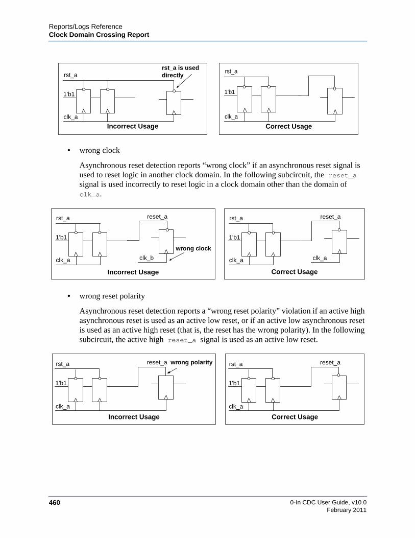
0-In CDC User Guide, v10.0460
Reports/Logs ReferenceClock Domain Crossing Report
February 2011
• wrong clock
Asynchronous reset detection reports “wrong clock” if an asynchronous reset signal isused to reset logic in another clock domain. In the following subcircuit, the reset_asignal is used incorrectly to reset logic in a clock domain other than the domain ofclk_a.
• wrong reset polarity
Asynchronous reset detection reports a “wrong reset polarity” violation if an active highasynchronous reset is used as an active low reset, or if an active low asynchronous resetis used as an active high reset (that is, the reset has the wrong polarity). In the followingsubcircuit, the active high reset_a signal is used as an active low reset.
1'b1
clk_a
rst_arst_a is useddirectly
1'b1
clk_a
rst_a
Incorrect Usage Correct Usage
1'b1
clk_a
rst_a reset_a
clk_b
wrong clock
1'b1
clk_a
rst_a reset_a
clk_a
Incorrect Usage Correct Usage
1'b1
clk_a
rst_a reset_a wrong polarity
1'b1
clk_a
rst_a reset_a
Incorrect Usage Correct Usage

Reports/Logs ReferenceClock Domain Crossing Report
0-In CDC User Guide, v10.0 461February 2011
All Transmitting SignalsThe automatically generated 0in_cdc.rpt file contains the transmitting signals that lists thesources of signals that cross clock domains as shown in Example 8-22.
Example 8-22. All Transmitting Signals
All Transmitting Signals (17)========================================================Name Width Location--------------------------------------------------------init_done 1 /demo_top.v:82pass_en[0] 1 /demo_top.v:79tx_sop 1 /demo_top.v:88tx_eop 1 /demo_top.v:87tx_mask_valid 1 /demo_top.v:90tx_en 1 /demo_top.v:86fstp[7:1] 7 /demo_top.v:81tx_mask_d 8 /demo_top.v:198crc_seed[7:1] 7 /demo_top.v:80fifo_1_d.wp_gray 5 /generic_fifo_dc_gray.v:147fifo_1_d.rp_gray 5 /generic_fifo_dc_gray.v:148fifo_0_h.wp_gray 5 /generic_fifo_dc_gray.v:147fifo_0_h.rp_gray 5 /generic_fifo_dc_gray.v:148fifo_1_d.u0.data 16 /dpmem2clk.v:58fifo_0_h.u0.data 16 /dpmem2clk.v:58pass_en[1] 1 /demo_top.v:79err_thrs 8 /demo_top.v:78
o Name – Signal name.
o Width – Number of bits.
o Location – Source code location.
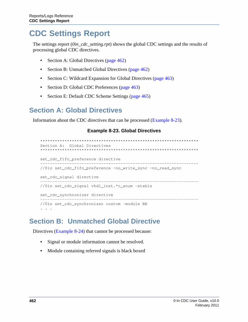
0-In CDC User Guide, v10.0462
Reports/Logs ReferenceCDC Settings Report
February 2011
CDC Settings ReportThe settings report (0in_cdc_setting.rpt) shows the global CDC settings and the results ofprocessing global CDC directives.
• Section A: Global Directives (page 462)
• Section B: Unmatched Global Directives (page 462)
• Section C: Wildcard Expansion for Global Directives (page 463)
• Section D: Global CDC Preferences (page 463)
• Section E: Default CDC Scheme Settings (page 465)
Section A: Global DirectivesInformation about the CDC directives that can be processed (Example 8-23).
Example 8-23. Global Directives
*****************************************************************Section A: Global Directives*****************************************************************
set_cdc_fifo_preference directive-----------------------------------------------------------------//0in set_cdc_fifo_preference -no_write_sync -no_read_sync
set_cdc_signal directive-----------------------------------------------------------------//0in set_cdc_signal vhdl_inst.*c_enum -stable
set_cdc_synchronizer directive-----------------------------------------------------------------//0in set_cdc_synchronizer custom -module BB. . .
Section B: Unmatched Global DirectiveDirectives (Example 8-24) that cannot be processed because:
• Signal or module information cannot be resolved.
• Module containing referred signals is black boxed
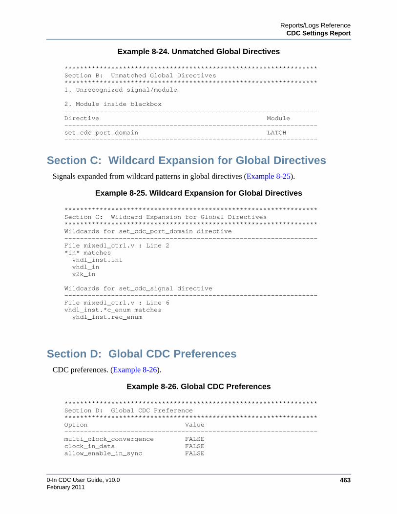
Reports/Logs ReferenceCDC Settings Report
0-In CDC User Guide, v10.0 463February 2011
Example 8-24. Unmatched Global Directives
*****************************************************************Section B: Unmatched Global Directives*****************************************************************1. Unrecognized signal/module
2. Module inside blackbox-----------------------------------------------------------------Directive Module-----------------------------------------------------------------set_cdc_port_domain LATCH-----------------------------------------------------------------
Section C: Wildcard Expansion for Global DirectivesSignals expanded from wildcard patterns in global directives (Example 8-25).
Example 8-25. Wildcard Expansion for Global Directives
*****************************************************************Section C: Wildcard Expansion for Global Directives*****************************************************************Wildcards for set_cdc_port_domain directive-----------------------------------------------------------------File mixed1_ctrl.v : Line 2*in* matches vhdl_inst.in1 vhdl_in v2k_in
Wildcards for set_cdc_signal directive-----------------------------------------------------------------File mixed1_ctrl.v : Line 6vhdl_inst.*c_enum matches vhdl_inst.rec_enum
Section D: Global CDC PreferencesCDC preferences. (Example 8-26).
Example 8-26. Global CDC Preferences
*****************************************************************Section D: Global CDC Preference*****************************************************************Option Value-----------------------------------------------------------------multi_clock_convergence FALSEclock_in_data FALSEallow_enable_in_sync FALSE

0-In CDC User Guide, v10.0464
Reports/Logs ReferenceCDC Settings Report
February 2011
max_cdc_crossings 0custom_fx FALSEpromote_reconvergence TRUEmult_fanout_async FALSEdmux_promote_sample FALSEfx_use_local_clk FALSEinput_async FALSEignore_black_box FALSEhandshake_scheme FALSEfifo_scheme TRUEdelayed_pulse FALSEreport_resets FALSEdetect_primary_output_clock FALSEformal_add_bus_stability FALSEformal_add_recon_stability FALSEfiltered_report FALSEvectorize_nl FALSEunrestricted_reconvergence FALSEno_clock_as_rx FALSEmulti_paths FALSEmulti_through FALSEreport_undriven_custom_sync FALSEprint_port_domain_template FALSEdmux_as_recon_start FALSEprint_detailed_custom_sync FALSEreport_bbox_recon FALSEblackbox_empty_module FALSEsample_data_stability FALSEinfer_clock_off FALSEdetect_pure_latch_clock FALSEpromote_async_reset FALSEcomplex_scheme_as_synchronizer FALSE

Reports/Logs ReferenceCDC Settings Report
0-In CDC User Guide, v10.0 465February 2011
Section E: Default CDC Scheme SettingsDefault severities and promotions for CDC schemes (Example 8-27).
Example 8-27. Default CDC Scheme Settings
******************************************************************************Section E: Default CDC Scheme Settings******************************************************************************CDC Scheme Severity Enabled Promotion Promotion Status------------------------------------------------------------------------------async_reset evaluation yes none offblackbox evaluation yes none offcustom_sync evaluation yes none offdff_sync_gated_clk evaluation yes cdc_sync onfour_latch evaluation yes cdc_sync oncustom_sync_with_crossing evaluation yes none offmemory_sync evaluation yes none offpulse_sync evaluation yes cdc_sync onshift_reg evaluation yes cdc_sync ontwo_dff evaluation yes cdc_sync onbus_dff_sync_gated_clk caution yes cdc_hamming_distance_one offdmux caution yes cdc_dsel onfifo caution no none offhandshake caution no none offmulti_bits caution yes cdc_sample onseries_redundant caution yes none offsimple_dmux caution yes cdc_dsel ontwo_dff_phase caution yes cdc_sync onasync_reset_no_sync violation yes none offbus_two_dff_phase violation yes cdc_hamming_distance_one offbus_four_latch violation yes cdc_hamming_distance_one offbus_two_dff violation yes cdc_hamming_distance_one offcombo_logic violation yes cdc_glitch onno_sync violation yes cdc_sample onbus_shift_reg violation yes cdc_hamming_distance_one offmulti_sync_mux_select violation yes cdc_sample onfanin_different_clks violation yes cdc_glitch onreconvergence violation yes depth:0 none offredundant violation yes none offsingle_source_reconvergence violation yes none off

0-In CDC User Guide, v10.0466
Reports/Logs ReferenceCDC Settings Report
February 2011

467
A B F GDC E H I J K L M N O P Q R S T U V XW Y Z
0-In CDC User Guide, v10.0February 2011
— Symbols —+0in_licq, 347+define+, 336+error, 363+incdir+, 336+libext, 336+nowarn, 363+skip_syscall, 69
— Numerics —0-In comments, 254
definition, 254single-line, 254
0in.log, 3680in_checkcsl.db, 3680in_db2ucdb, 3530in_detail.log, 3681-Step compilation, 562-Step compilation, 57
— A —abstract memory model, 308ad hoc synchronizer, 31-allow_enable_in_sync, 283Altera, 63assertion defined, 47assertion-based verification, 47-assume, 402Assumption groups
data, 394deq, 383dist, 388enq, 383max, 394min, 394ptr, 383rptr, 383rxdata, 378rxdone, 394rxval, 394
stable, 388txdata, 378txdone, 394txdsel, 378txval, 394wptr, 383
async_reset scheme, 181async_reset_no_sync scheme, 184asynchronous
clocks, 25inputs, 25no synchronizer, 459reset detection, 458reset signals, 459reset synchronizers, 458reset with missing synchronizer, 459user-entered reset, 459wrong clock, 460wrong reset polarity, 460
-auto_blackbox, 364
— B —Black box, 69blackbox scheme, 186-blackbox_empty_module, 285, 286Block constraints generation mode, 119Block specifications, 120Bookmarks, 432bus_dff_sync_gated_clk scheme, 191bus_four_latch scheme, 193bus_shift_reg scheme, 195bus_two_dff scheme, 197bus_two_dff_phase scheme, 199
— C —–cache, 361Case directive, non-native, 324CDC
cautions report, 454evaluation report, 455, 456
Index
468February 2011
0-In CDC User Guide, v10.0
A B F GDC E H I J K L M N O P Q R S T U V XW Y Z
filtered crossings, 362promotion, 104promotion summary report, 453scheme types, 39scheme, turn off reporting, 40schemes, 39, 179schemes with potential errors, 44summary report, 452violation report, 453
CDC checks window, 419cdc command, 359CDC port constraint, 273cdc_dsel, 377cdc_fifo, 381cdc_glitch, 385cdc_hamming_distance_one, 387-cdc_handshake, 391cdc_handshake_data, 390cdc_sample, 398cdc_sync, 401, 404, 408CDC-FX
cdc_fx checker, 175metastability injected simulation, 29
Checkerpromotion, 48
checkercdc_fx, 159promotion, 40protocol, 47simulate a design, 50
Checker summary, 287Checker types
cdc_dsel, 377cdc_fifo, 381cdc_glitch, 385cdc_hamming_distance_one, 387cdc_handshake_data, 390cdc_sample, 398cdc_sync, 401, 404, 408
CheckerWare assertion library, 48clock
asynchronous, 25domain crossing, 26domains, 25group, 25
group inferred by compiler, 447group summary, 446jitter, 28user-specified clock group, 447
clock domaincrossing report file, 452
-clock_as_rx, 286-clock_group_pair, 273-clock_in_data, 283Clocks, 25Clocks window, 443–cmd, 348combo_logic scheme, 201Configure columns buttons, 413Consistency checks, 123Control file models, 131control signal synchronizers, 31Corner cases
all one, 399all one to zero, 399all zero, 399all zero to one, 399asserted for ’tx_min’ cycles, 379FIFO is empty, 383FIFO is full, 383turnaround cycles completed at
’turnaround_max’, 395turnaround cycles completed at
’turnaround_min’, 395value changed at ’tx_min’, 388, 402
counterexample, 49Coverage count, 356csl, 373csl input files, 368–cuname, 361Current layout, 417-custom_fx, 284custom_sync scheme, 189, 203, 205
— D —data
synchronization, 42, 43Data sheets, checkers, 375-data_stable, 391–de, 363Defaults file, 58

4690-In CDC User Guide, v10.0February 2011
A B F GDC E H I J K L M N O P Q R S T U V XW Y Z
-delayed_pulse, 284-depth, 381Depth of divergence, 37Depth of reconvergence, 37-deq, 381-dequeue, 382, 401design
detailed information, 449general information, 449
Design window, 441–detail, 347Details window, 422-detect_primary_output_clock, 284dff_sync_gated_clk scheme, 207Directive order, 259Directives
non-native case, 324Directives window, 444Divergence depth, 37Dividers, 436dmux scheme, 208, 244-dmux_as_recon_start, 285-dmux_promote_sample, 284Dock button, 416Drag-and-drop, 412
— E —Empty modules, 285-enq, 381-enqueue, 382, 402Errors/Warnings window, 418Evals, 375Evaluation statistic, 375exact memory model, 308Expansion, 257
— F —Failure count, 356fanin_different_clks scheme, 210-fifo_scheme, 284files
0in_cdc_design.rpt, 446automatically generated, 445design report, 446
filteredCDC crossings, 362
-filtered_report, 285Filtering CDC results, 100Find panel, 440formal
constraint, 49target, 49tools, 49verification, 49
Formal block restrictions, 69Formal CDC, 46Formal CDC effort level, 46-formal_add_bus_stability, 285-formal_add_recon_stability, 285four_latch scheme, 218FPGA resource libraries, 63Functions, 73
— G —–G, 363–g, 364-glitch, 385Global CDC preferences, 119global directives
create_wire, 315disable_checker, 318set_cdc_port_domain, 279set_cdc_preference, 287set_cdc_reconvergence, 292set_cdc_report, 296set_cdc_signal, 300set_cdc_synchronizer, 303set_checker_action, 322set_constant_propagation, 306set_memory, 308set_mode, 310set_mode_control, 311wildcarded signals, 362
Global reconvergence, 35Gray-coding protocol, 47
— H —-hamming_one, 387-handshake_scheme, 284Hierarchical constraints control file, 119hierarchical verification
use model, 118

470February 2011
0-In CDC User Guide, v10.0
A B F GDC E H I J K L M N O P Q R S T U V XW Y Z
-hold, 399Homogeneous instances of a block, 129Hover help, 412
— I —-ignore_black_box, 285Inconclusive, 46Inferred black box, 69-input_async, 284
— J —jitter, 28
— L —–l, 347–L/-Lf, 334, 361–libmap, 334–libmap_verbose, 334Library section, 61–limit_messages, 347Local reconvergence, 35-locklib, 326, 327
— M —-max_cdc_crossings number, 283mean-time-between-failure, 26memory
increase, 296memory_sync scheme, 223metastability
cdc_fx checker, 159fence logic, 30in hardware, 26in RTL simulation, 27injection, 159metastable flip-flops, 26registers, 26windows, 160
modal analysiscapabilities, 133
modereport information, 451
modelsim.ini, 58, 61–modelsimini, 330, 334, 360Modules window, 442Move-window button
Buttons
Move-window, 415MTBF, 26-mult_fanout_async, 284multi_bits scheme, 225-multi_clock_convergence, 283multi_sync_mux_select scheme, 227Multibit reconvergence, 35Multicycle reconvergence, 36Multiple always blocks, 73Multiple directives, 254
— N —netlist analysis, 45–nl, 347no_sync scheme, 229, 231Non-native case directives, 324
— O —Objects window, 423–od, 347out-of-band signals, 30override_on/override_off, 70
— P —Parser directives, 70Pass count, 356Path ID, 49PLI
function calls, 171Popup menus, 411port
domain information, 450Port constraints, 273-ports, 273Pragmas, 70-print_detailed_custom_sync, 286-print_port_domain_template, 286Project mode, 91Project window, 440-promote_reconvergence, 284Promoted checkers, 48promotion, 40pulse_sync scheme, 233
— Q —question mark (?) wildcard, 311

4710-In CDC User Guide, v10.0February 2011
A B F GDC E H I J K L M N O P Q R S T U V XW Y Z
— R —-rd_ptr, 382-rd_ptr_check, 382reconvergence
defined, 35scheme, 235, 246
Reconvergence depth, 37redundant scheme, 238, 240-registered, 402–rel_paths, 347Report clocks, 93Resource libraries, 60-restore_state, 349Restrictions
formal block, 69runtime
increase, 296-rx_clock, 377, 382, 391, 398-rx_clock_group, 273-rx_data_select, 378-rx_data_stable, 378-rx_done, 394-rx_done_assert_until_rx_valid_deassert, 393-rx_min, 393-rx_reset, 377, 382, 391, 398-rx_valid, 394-rx_valid_assert_until_rx_done_assert, 392-rx_var, 398
— S —-sample_data_stability, 284Saving the current layout, 417schemes
async_reset, 181async_reset_no_sync, 184blackbox, 186bus_dff_sync_gated_clk, 191bus_four_latch, 193bus_shift_reg, 195bus_two_dff, 197bus_two_dff_phase, 199CDC, 39combo_logic, 201custom_sync, 189, 203, 205dff_sync_gated_clk, 207
dmux, 208, 244fanin_different_clks, 210four_latch, 218memory_sync, 223multi_bits, 225multi_sync_mux_select, 227no_sync, 229, 231potential problems, 44pulse_sync, 233reconvergence, 235, 246redundant, 238, 240shift_reg, 242two_dff, 251two_dff_phase, 253
set_black_box, 69set_constant_propagation, 306set_memory, 308-setup, 399severity level
caution, 39evaluation, 40violation, 39waived, 40
shift_reg scheme, 242Signal dividers, 436Signal stability protocol, 46signals
out-of-band, 30transmitting, 461
–sim, 347simulation
checkers in simulation, 50transfer protocol, 30
Single-source reconvergence, 37, 246Skipping modules, 69specifying design intent, 47stability protocol, 46-stable, 401Standard options
definition, 375Static formal analysis, 91Statistics
current FIFO entries, 383cycles checked (evals), 386dequeues, 383
472February 2011
0-In CDC User Guide, v10.0
A B F GDC E H I J K L M N O P Q R S T U V XW Y Z
enqueues, 383enqueues and dequeues (evals), 383longest assertion, 379longest stable time, 388, 402maximum FIFO entries, 383maximum turnaround cycles, 395minimum turnaround cycles, 395one to zero transition bitmap, 400sample one bitmap, 399sample zero bitmap, 399shortest assertion, 379shortest stable time, 388, 402total turnaround cycles, 395total tx_valid, 395transfers checked, 379values checked enqueues and dequeues
(Evals), 402values checked enqueues and dequeues
(evals), 388values sampled (evals), 399zero to one transition bitmap, 400
Status flags, 53Stretch-shrink bars, 415structured synchronizers, 31Stub modules, 285synchronization
custom modules, 458data, 42, 43scheme, 30, 48
synchronizerad hoc, 31asynchronous reset, 458block diagram, 30control signal, 31structured, 31
synthesis_off/synthesis_on, 70
— T —Target design, 152Tasks, 73transfer protocol, 30translate_off regions, 70transmitting signals, 461-turnaround_max, 393-turnaround_min, 393two_dff scheme, 251
two_dff_phase scheme, 253-tx_clock, 377, 382, 387, 391, 398, 401-tx_clock_group, 273-tx_data, 377, 391, 401-tx_data_select, 378-tx_data_stable, 378-tx_done, 394-tx_done_assert_until_tx_valid_deassert, 392-tx_min, 378, 388, 393-tx_min_check, 378-tx_reset, 377, 382, 387, 391, 398, 401-tx_valid, 391-tx_valid_assert_until_tx_done_assert, 392-tx_valid_deassert_until_tx_done_deassert,
392-tx_var, 387, 398, 401
— U —Undock button, 416Unresolved modules, 364Unsynthesizable code, 72Unzoom button, 415-used, 385
— V —–v, 338-var, 385-vectorize_nl, 285verification
formal, 49–version, 347–vhctrl, 361
— W —Waiver file, 127Wave view
Bookmarks, 432–wd, 347Wildcards
Directive order, 259Patterns, 257
wildcardsin variables and wire names, 294question mark(?), 311with global directives, 265, 300, 362
Windows

4730-In CDC User Guide, v10.0February 2011
A B F GDC E H I J K L M N O P Q R S T U V XW Y Z
CDC checks, 419Clocks, 443Design, 441Details, 422Directives, 444Errors/Warnings, 418Modules, 442objects, 423Project, 440
–work, 360-wr_ptr, 382-wr_ptr_check, 382
— X —Xilinx, 63
— Y —–y, 338
— Z —Zoom button, 415

474February 2011
0-In CDC User Guide, v10.0
A B F GDC E H I J K L M N O P Q R S T U V XW Y Z

End-User License AgreementThe latest version of the End-User License Agreement is available on-line at:
www.mentor.com/eula
END-USER LICENSE AGREEMENT (“Agreement”)
This is a legal agreement concerning the use of Software (as defined in Section 2) and hardware (collectively“Products”) between the company acquiring the Products (“Customer”), and the Mentor Graphics entity thatissued the corresponding quotation or, if no quotation was issued, the applicable local Mentor Graphics entity(“Mentor Graphics”). Except for license agreements related to the subject matter of this license agreement whichare physically signed by Customer and an authorized representative of Mentor Graphics, this Agreement and theapplicable quotation contain the parties' entire understanding relating to the subject matter and supersede allprior or contemporaneous agreements. If Customer does not agree to these terms and conditions, promptly returnor, in the case of Software received electronically, certify destruction of Software and all accompanying itemswithin five days after receipt of Software and receive a full refund of any license fee paid.
1. ORDERS, FEES AND PAYMENT.
1.1. To the extent Customer (or if agreed by Mentor Graphics, Customer’s appointed third party buying agent) places andMentor Graphics accepts purchase orders pursuant to this Agreement (“Order(s)”), each Order will constitute a contractbetween Customer and Mentor Graphics, which shall be governed solely and exclusively by the terms and conditions of thisAgreement, any applicable addenda and the applicable quotation, whether or not these documents are referenced on theOrder. Any additional or conflicting terms and conditions appearing on an Order will not be effective unless agreed inwriting by an authorized representative of Customer and Mentor Graphics.
1.2. Amounts invoiced will be paid, in the currency specified on the applicable invoice, within 30 days from the date of suchinvoice. Any past due invoices will be subject to the imposition of interest charges in the amount of one and one-halfpercent per month or the applicable legal rate currently in effect, whichever is lower. Prices do not include freight,insurance, customs duties, taxes or other similar charges, which Mentor Graphics will state separately in the applicableinvoice(s). Unless timely provided with a valid certificate of exemption or other evidence that items are not taxable, MentorGraphics will invoice Customer for all applicable taxes including, but not limited to, VAT, GST, sales tax and service tax.Customer will make all payments free and clear of, and without reduction for, any withholding or other taxes; any suchtaxes imposed on payments by Customer hereunder will be Customer’s sole responsibility. If Customer appoints a thirdparty to place purchase orders and/or make payments on Customer’s behalf, Customer shall be liable for payment underOrders placed by such third party in the event of default.
1.3. All Products are delivered FCA factory (Incoterms 2000), freight prepaid and invoiced to Customer, except Softwaredelivered electronically, which shall be deemed delivered when made available to Customer for download. MentorGraphics retains a security interest in all Products delivered under this Agreement, to secure payment of the purchase priceof such Products, and Customer agrees to sign any documents that Mentor Graphics determines to be necessary orconvenient for use in filing or perfecting such security interest. Mentor Graphics’ delivery of Software by electronic meansis subject to Customer’s provision of both a primary and an alternate e-mail address.
2. GRANT OF LICENSE. The software installed, downloaded, or otherwise acquired by Customer under this Agreement,including any updates, modifications, revisions, copies, documentation and design data (“Software”) are copyrighted, tradesecret and confidential information of Mentor Graphics or its licensors, who maintain exclusive title to all Software and retainall rights not expressly granted by this Agreement. Mentor Graphics grants to Customer, subject to payment of applicablelicense fees, a nontransferable, nonexclusive license to use Software solely: (a) in machine-readable, object-code form (exceptas provided in Subsection 5.2); (b) for Customer’s internal business purposes; (c) for the term of the license; and (d) on thecomputer hardware and at the site authorized by Mentor Graphics. A site is restricted to a one-half mile (800 meter) radius.Customer may have Software temporarily used by an employee for telecommuting purposes from locations other than aCustomer office, such as the employee's residence, an airport or hotel, provided that such employee's primary place ofemployment is the site where the Software is authorized for use. Mentor Graphics’ standard policies and programs, which varydepending on Software, license fees paid or services purchased, apply to the following: (a) relocation of Software; (b) use ofSoftware, which may be limited, for example, to execution of a single session by a single user on the authorized hardware or fora restricted period of time (such limitations may be technically implemented through the use of authorization codes or similardevices); and (c) support services provided, including eligibility to receive telephone support, updates, modifications, andrevisions. For the avoidance of doubt, if Customer requests any change or enhancement to Software, whether in the course of
IMPORTANT INFORMATION
USE OF ALL SOFTWARE IS SUBJECT TO LICENSE RESTRICTIONS. CAREFULLY READ THISLICENSE AGREEMENT BEFORE USING THE PRODUCTS. USE OF SOFTWARE INDICATES
CUSTOMER’S COMPLETE AND UNCONDITIONAL ACCEPTANCE OF THE TERMS ANDCONDITIONS SET FORTH IN THIS AGREEMENT. ANY ADDITIONAL OR DIFFERENT PURCHASE
ORDER TERMS AND CONDITIONS SHALL NOT APPLY.

receiving support or consulting services, evaluating Software, performing beta testing or otherwise, any inventions, productimprovements, modifications or developments made by Mentor Graphics (at Mentor Graphics’ sole discretion) will be theexclusive property of Mentor Graphics.
3. ESC SOFTWARE. If Customer purchases a license to use development or prototyping tools of Mentor Graphics’ EmbeddedSoftware Channel (“ESC”), Mentor Graphics grants to Customer a nontransferable, nonexclusive license to reproduce anddistribute executable files created using ESC compilers, including the ESC run-time libraries distributed with ESC C and C++compiler Software that are linked into a composite program as an integral part of Customer’s compiled computer program,provided that Customer distributes these files only in conjunction with Customer’s compiled computer program. MentorGraphics does NOT grant Customer any right to duplicate, incorporate or embed copies of Mentor Graphics’ real-time operatingsystems or other embedded software products into Customer’s products or applications without first signing or otherwiseagreeing to a separate agreement with Mentor Graphics for such purpose.
4. BETA CODE.
4.1. Portions or all of certain Software may contain code for experimental testing and evaluation (“Beta Code”), which may notbe used without Mentor Graphics’ explicit authorization. Upon Mentor Graphics’ authorization, Mentor Graphics grants toCustomer a temporary, nontransferable, nonexclusive license for experimental use to test and evaluate the Beta Codewithout charge for a limited period of time specified by Mentor Graphics. This grant and Customer’s use of the Beta Codeshall not be construed as marketing or offering to sell a license to the Beta Code, which Mentor Graphics may choose not torelease commercially in any form.
4.2. If Mentor Graphics authorizes Customer to use the Beta Code, Customer agrees to evaluate and test the Beta Code undernormal conditions as directed by Mentor Graphics. Customer will contact Mentor Graphics periodically during Customer’suse of the Beta Code to discuss any malfunctions or suggested improvements. Upon completion of Customer’s evaluationand testing, Customer will send to Mentor Graphics a written evaluation of the Beta Code, including its strengths,weaknesses and recommended improvements.
4.3. Customer agrees to maintain Beta Code in confidence and shall restrict access to the Beta Code, including the methods andconcepts utilized therein, solely to those employees and Customer location(s) authorized by Mentor Graphics to performbeta testing. Customer agrees that any written evaluations and all inventions, product improvements, modifications ordevelopments that Mentor Graphics conceived or made during or subsequent to this Agreement, including those basedpartly or wholly on Customer’s feedback, will be the exclusive property of Mentor Graphics. Mentor Graphics will haveexclusive rights, title and interest in all such property. The provisions of this Subsection 4.3 shall survive termination of thisAgreement.
5. RESTRICTIONS ON USE.
5.1. Customer may copy Software only as reasonably necessary to support the authorized use. Each copy must include allnotices and legends embedded in Software and affixed to its medium and container as received from Mentor Graphics. Allcopies shall remain the property of Mentor Graphics or its licensors. Customer shall maintain a record of the number andprimary location of all copies of Software, including copies merged with other software, and shall make those recordsavailable to Mentor Graphics upon request. Customer shall not make Products available in any form to any person otherthan Customer’s employees and on-site contractors, excluding Mentor Graphics competitors, whose job performancerequires access and who are under obligations of confidentiality. Customer shall take appropriate action to protect theconfidentiality of Products and ensure that any person permitted access does not disclose or use it except as permitted bythis Agreement. Customer shall give Mentor Graphics written notice of any unauthorized disclosure or use of the Productsas soon as Customer learns or becomes aware of such unauthorized disclosure or use. Except as otherwise permitted forpurposes of interoperability as specified by applicable and mandatory local law, Customer shall not reverse-assemble,reverse-compile, reverse-engineer or in any way derive any source code from Software. Log files, data files, rule files andscript files generated by or for the Software (collectively “Files”), including without limitation files containing StandardVerification Rule Format (“SVRF”) and Tcl Verification Format (“TVF”) which are Mentor Graphics’ proprietary syntaxesfor expressing process rules, constitute or include confidential information of Mentor Graphics. Customer may share Fileswith third parties, excluding Mentor Graphics competitors, provided that the confidentiality of such Files is protected bywritten agreement at least as well as Customer protects other information of a similar nature or importance, but in any casewith at least reasonable care. Customer may use Files containing SVRF or TVF only with Mentor Graphics products. Underno circumstances shall Customer use Software or Files or allow their use for the purpose of developing, enhancing ormarketing any product that is in any way competitive with Software, or disclose to any third party the results of, orinformation pertaining to, any benchmark.
5.2. If any Software or portions thereof are provided in source code form, Customer will use the source code only to correctsoftware errors and enhance or modify the Software for the authorized use. Customer shall not disclose or permit disclosureof source code, in whole or in part, including any of its methods or concepts, to anyone except Customer’s employees orcontractors, excluding Mentor Graphics competitors, with a need to know. Customer shall not copy or compile source codein any manner except to support this authorized use.
5.3. Customer may not assign this Agreement or the rights and duties under it, or relocate, sublicense or otherwise transfer theProducts, whether by operation of law or otherwise (“Attempted Transfer”), without Mentor Graphics’ prior writtenconsent and payment of Mentor Graphics’ then-current applicable relocation and/or transfer fees. Any Attempted Transferwithout Mentor Graphics’ prior written consent shall be a material breach of this Agreement and may, at Mentor Graphics’option, result in the immediate termination of the Agreement and/or the licenses granted under this Agreement. The terms
of this Agreement, including without limitation the licensing and assignment provisions, shall be binding upon Customer’spermitted successors in interest and assigns.
5.4. The provisions of this Section 5 shall survive the termination of this Agreement.
6. SUPPORT SERVICES. To the extent Customer purchases support services, Mentor Graphics will provide Customer updatesand technical support for the Products, at the Customer site(s) for which support is purchased, in accordance with MentorGraphics’ then current End-User Support Terms located at http://supportnet.mentor.com/about/legal/.
7. AUTOMATIC CHECK FOR UPDATES; PRIVACY. Technological measures in Software may communicate with serversof Mentor Graphics or its contractors for the purpose of checking for and notifying the user of updates and to ensure that theSoftware in use is licensed in compliance with this Agreement. Mentor Graphics will not collect any personally identifiable datain this process and will not disclose any data collected to any third party without the prior written consent of Customer, except toMentor Graphics’ outside attorneys or as may be required by a court of competent jurisdiction.
8. LIMITED WARRANTY.
8.1. Mentor Graphics warrants that during the warranty period its standard, generally supported Products, when properlyinstalled, will substantially conform to the functional specifications set forth in the applicable user manual. MentorGraphics does not warrant that Products will meet Customer’s requirements or that operation of Products will beuninterrupted or error free. The warranty period is 90 days starting on the 15th day after delivery or upon installation,whichever first occurs. Customer must notify Mentor Graphics in writing of any nonconformity within the warranty period.For the avoidance of doubt, this warranty applies only to the initial shipment of Software under an Order and does notrenew or reset, for example, with the delivery of (a) Software updates or (b) authorization codes or alternate Software undera transaction involving Software re-mix. This warranty shall not be valid if Products have been subject to misuse,unauthorized modification or improper installation. MENTOR GRAPHICS’ ENTIRE LIABILITY AND CUSTOMER’SEXCLUSIVE REMEDY SHALL BE, AT MENTOR GRAPHICS’ OPTION, EITHER (A) REFUND OF THE PRICEPAID UPON RETURN OF THE PRODUCTS TO MENTOR GRAPHICS OR (B) MODIFICATION ORREPLACEMENT OF THE PRODUCTS THAT DO NOT MEET THIS LIMITED WARRANTY, PROVIDEDCUSTOMER HAS OTHERWISE COMPLIED WITH THIS AGREEMENT. MENTOR GRAPHICS MAKES NOWARRANTIES WITH RESPECT TO: (A) SERVICES; (B) PRODUCTS PROVIDED AT NO CHARGE; OR (C) BETACODE; ALL OF WHICH ARE PROVIDED “AS IS.”
8.2. THE WARRANTIES SET FORTH IN THIS SECTION 8 ARE EXCLUSIVE. NEITHER MENTOR GRAPHICS NORITS LICENSORS MAKE ANY OTHER WARRANTIES EXPRESS, IMPLIED OR STATUTORY, WITH RESPECT TOPRODUCTS PROVIDED UNDER THIS AGREEMENT. MENTOR GRAPHICS AND ITS LICENSORSSPECIFICALLY DISCLAIM ALL IMPLIED WARRANTIES OF MERCHANTABILITY, FITNESS FOR APARTICULAR PURPOSE AND NON-INFRINGEMENT OF INTELLECTUAL PROPERTY.
9. LIMITATION OF LIABILITY. EXCEPT WHERE THIS EXCLUSION OR RESTRICTION OF LIABILITY WOULD BEVOID OR INEFFECTIVE UNDER APPLICABLE LAW, IN NO EVENT SHALL MENTOR GRAPHICS OR ITSLICENSORS BE LIABLE FOR INDIRECT, SPECIAL, INCIDENTAL, OR CONSEQUENTIAL DAMAGES (INCLUDINGLOST PROFITS OR SAVINGS) WHETHER BASED ON CONTRACT, TORT OR ANY OTHER LEGAL THEORY, EVENIF MENTOR GRAPHICS OR ITS LICENSORS HAVE BEEN ADVISED OF THE POSSIBILITY OF SUCH DAMAGES. INNO EVENT SHALL MENTOR GRAPHICS’ OR ITS LICENSORS’ LIABILITY UNDER THIS AGREEMENT EXCEEDTHE AMOUNT RECEIVED FROM CUSTOMER FOR THE HARDWARE, SOFTWARE LICENSE OR SERVICE GIVINGRISE TO THE CLAIM. IN THE CASE WHERE NO AMOUNT WAS PAID, MENTOR GRAPHICS AND ITS LICENSORSSHALL HAVE NO LIABILITY FOR ANY DAMAGES WHATSOEVER. THE PROVISIONS OF THIS SECTION 9 SHALLSURVIVE THE TERMINATION OF THIS AGREEMENT.
10. HAZARDOUS APPLICATIONS. CUSTOMER ACKNOWLEDGES IT IS SOLELY RESPONSIBLE FOR TESTING ITSPRODUCTS USED IN APPLICATIONS WHERE THE FAILURE OR INACCURACY OF ITS PRODUCTS MIGHTRESULT IN DEATH OR PERSONAL INJURY (“HAZARDOUS APPLICATIONS”). NEITHER MENTOR GRAPHICSNOR ITS LICENSORS SHALL BE LIABLE FOR ANY DAMAGES RESULTING FROM OR IN CONNECTION WITHTHE USE OF MENTOR GRAPHICS PRODUCTS IN OR FOR HAZARDOUS APPLICATIONS. THE PROVISIONS OFTHIS SECTION 10 SHALL SURVIVE THE TERMINATION OF THIS AGREEMENT.
11. INDEMNIFICATION. CUSTOMER AGREES TO INDEMNIFY AND HOLD HARMLESS MENTOR GRAPHICS ANDITS LICENSORS FROM ANY CLAIMS, LOSS, COST, DAMAGE, EXPENSE OR LIABILITY, INCLUDINGATTORNEYS’ FEES, ARISING OUT OF OR IN CONNECTION WITH THE USE OF PRODUCTS AS DESCRIBED INSECTION 10. THE PROVISIONS OF THIS SECTION 11 SHALL SURVIVE THE TERMINATION OF THISAGREEMENT.
12. INFRINGEMENT.
12.1. Mentor Graphics will defend or settle, at its option and expense, any action brought against Customer in the United States,Canada, Japan, or member state of the European Union which alleges that any standard, generally supported Productacquired by Customer hereunder infringes a patent or copyright or misappropriates a trade secret in such jurisdiction.Mentor Graphics will pay costs and damages finally awarded against Customer that are attributable to the action. Customerunderstands and agrees that as conditions to Mentor Graphics’ obligations under this section Customer must: (a) notifyMentor Graphics promptly in writing of the action; (b) provide Mentor Graphics all reasonable information and assistance

to settle or defend the action; and (c) grant Mentor Graphics sole authority and control of the defense or settlement of theaction.
12.2. If a claim is made under Subsection 12.1 Mentor Graphics may, at its option and expense, (a) replace or modify the Productso that it becomes noninfringing; (b) procure for Customer the right to continue using the Product; or (c) require the returnof the Product and refund to Customer any purchase price or license fee paid, less a reasonable allowance for use.
12.3. Mentor Graphics has no liability to Customer if the action is based upon: (a) the combination of Software or hardware withany product not furnished by Mentor Graphics; (b) the modification of the Product other than by Mentor Graphics; (c) theuse of other than a current unaltered release of Software; (d) the use of the Product as part of an infringing process; (e) aproduct that Customer makes, uses, or sells; (f) any Beta Code or Product provided at no charge; (g) any software providedby Mentor Graphics’ licensors who do not provide such indemnification to Mentor Graphics’ customers; or(h) infringement by Customer that is deemed willful. In the case of (h), Customer shall reimburse Mentor Graphics for itsreasonable attorney fees and other costs related to the action.
12.4. THIS SECTION 12 IS SUBJECT TO SECTION 9 ABOVE AND STATES THE ENTIRE LIABILITY OF MENTORGRAPHICS AND ITS LICENSORS FOR DEFENSE, SETTLEMENT AND DAMAGES, AND CUSTOMER’S SOLEAND EXCLUSIVE REMEDY, WITH RESPECT TO ANY ALLEGED PATENT OR COPYRIGHT INFRINGEMENTOR TRADE SECRET MISAPPROPRIATION BY ANY PRODUCT PROVIDED UNDER THIS AGREEMENT.
13. TERMINATION AND EFFECT OF TERMINATION. If a Software license was provided for limited term use, such licensewill automatically terminate at the end of the authorized term.
13.1. Mentor Graphics may terminate this Agreement and/or any license granted under this Agreement immediately upon writtennotice if Customer: (a) exceeds the scope of the license or otherwise fails to comply with the licensing or confidentialityprovisions of this Agreement, or (b) becomes insolvent, files a bankruptcy petition, institutes proceedings for liquidation orwinding up or enters into an agreement to assign its assets for the benefit of creditors. For any other material breach of anyprovision of this Agreement, Mentor Graphics may terminate this Agreement and/or any license granted under thisAgreement upon 30 days written notice if Customer fails to cure the breach within the 30 day notice period. Termination ofthis Agreement or any license granted hereunder will not affect Customer’s obligation to pay for Products shipped orlicenses granted prior to the termination, which amounts shall be payable immediately upon the date of termination.
13.2. Upon termination of this Agreement, the rights and obligations of the parties shall cease except as expressly set forth in thisAgreement. Upon termination, Customer shall ensure that all use of the affected Products ceases, and shall return hardwareand either return to Mentor Graphics or destroy Software in Customer’s possession, including all copies anddocumentation, and certify in writing to Mentor Graphics within ten business days of the termination date that Customer nolonger possesses any of the affected Products or copies of Software in any form.
14. EXPORT. The Products provided hereunder are subject to regulation by local laws and United States government agencies,which prohibit export or diversion of certain products and information about the products to certain countries and certainpersons. Customer agrees that it will not export Products in any manner without first obtaining all necessary approval fromappropriate local and United States government agencies.
15. U.S. GOVERNMENT LICENSE RIGHTS. Software was developed entirely at private expense. All Software is commercialcomputer software within the meaning of the applicable acquisition regulations. Accordingly, pursuant to US FAR 48 CFR12.212 and DFAR 48 CFR 227.7202, use, duplication and disclosure of the Software by or for the U.S. Government or a U.S.Government subcontractor is subject solely to the terms and conditions set forth in this Agreement, except for provisions whichare contrary to applicable mandatory federal laws.
16. THIRD PARTY BENEFICIARY. Mentor Graphics Corporation, Mentor Graphics (Ireland) Limited, Microsoft Corporationand other licensors may be third party beneficiaries of this Agreement with the right to enforce the obligations set forth herein.
17. REVIEW OF LICENSE USAGE. Customer will monitor the access to and use of Software. With prior written notice andduring Customer’s normal business hours, Mentor Graphics may engage an internationally recognized accounting firm toreview Customer’s software monitoring system and records deemed relevant by the internationally recognized accounting firmto confirm Customer’s compliance with the terms of this Agreement or U.S. or other local export laws. Such review may includeFLEXlm or FLEXnet (or successor product) report log files that Customer shall capture and provide at Mentor Graphics’request. Customer shall make records available in electronic format and shall fully cooperate with data gathering to support thelicense review. Mentor Graphics shall bear the expense of any such review unless a material non-compliance is revealed. MentorGraphics shall treat as confidential information all information gained as a result of any request or review and shall only use ordisclose such information as required by law or to enforce its rights under this Agreement. The provisions of this Section 17shall survive the termination of this Agreement.
18. CONTROLLING LAW, JURISDICTION AND DISPUTE RESOLUTION. The owners of certain Mentor Graphicsintellectual property licensed under this Agreement are located in Ireland and the United States. To promote consistency aroundthe world, disputes shall be resolved as follows: excluding conflict of laws rules, this Agreement shall be governed by andconstrued under the laws of the State of Oregon, USA, if Customer is located in North or South America, and the laws of Irelandif Customer is located outside of North or South America. All disputes arising out of or in relation to this Agreement shall besubmitted to the exclusive jurisdiction of the courts of Portland, Oregon when the laws of Oregon apply, or Dublin, Ireland whenthe laws of Ireland apply. Notwithstanding the foregoing, all disputes in Asia arising out of or in relation to this Agreement shallbe resolved by arbitration in Singapore before a single arbitrator to be appointed by the chairman of the Singapore International

Arbitration Centre (“SIAC”) to be conducted in the English language, in accordance with the Arbitration Rules of the SIAC ineffect at the time of the dispute, which rules are deemed to be incorporated by reference in this section. This section shall notrestrict Mentor Graphics’ right to bring an action against Customer in the jurisdiction where Customer’s place of business islocated. The United Nations Convention on Contracts for the International Sale of Goods does not apply to this Agreement.
19. SEVERABILITY. If any provision of this Agreement is held by a court of competent jurisdiction to be void, invalid,unenforceable or illegal, such provision shall be severed from this Agreement and the remaining provisions will remain in fullforce and effect.
20. MISCELLANEOUS. This Agreement contains the parties’ entire understanding relating to its subject matter and supersedes allprior or contemporaneous agreements, including but not limited to any purchase order terms and conditions. Some Softwaremay contain code distributed under a third party license agreement that may provide additional rights to Customer. Please seethe applicable Software documentation for details. This Agreement may only be modified in writing by authorizedrepresentatives of the parties. Waiver of terms or excuse of breach must be in writing and shall not constitute subsequentconsent, waiver or excuse.
Rev. 100615, Part No. 246066


