CAx-IF Recommended Practices - CAx Implementor Forum · CAx-IF Recommended Practices for the...
102
CAx-IF Recommended Practices for the Representation and Presentation of Product Manufac- turing Information (PMI) (AP242) Version 4.0, October 13, 2014 Status: Release Contacts: CAx-IF Jochen Boy PROSTEP AG Dolivostraße 11 64293 Darmstadt / Germany [email protected] Phil Rosché ACCR LLC. 125 King Charles Circle Summerville, SC 29485 USA [email protected] Technical Ed Paff ITI TranscenData 5303 Dupont Circle Milford, OH 45150 USA [email protected] Bryan Fischer Advanced Dimensional Management LLC 16004 Tualatin-Sherwood Road #163 Sherwood, OR 97140 USA [email protected] © CAx Implementor Forum
Transcript of CAx-IF Recommended Practices - CAx Implementor Forum · CAx-IF Recommended Practices for the...

CAx-IF Recommended Practices
for the
Representation and Presentation of Product Manufac-turing Information (PMI) (AP242)
Version 4.0, October 13, 2014
Status: Release
Contacts:
CAx-IF
Jochen Boy PROSTEP AG Dolivostraße 11 64293 Darmstadt / Germany [email protected]
Phil Rosché ACCR LLC. 125 King Charles Circle Summerville, SC 29485 USA [email protected]
Technical
Ed Paff ITI TranscenData 5303 Dupont Circle Milford, OH 45150 USA [email protected]
Bryan Fischer Advanced Dimensional Management LLC 16004 Tualatin-Sherwood Road #163 Sherwood, OR 97140 USA [email protected]
© CAx Implementor Forum

CAx-IF Recommended Practices Representation and Presentation of Product Manufacturing Information (PMI) (AP242) Version 4.0, October 13, 2014
© CAx Implementor Forum http://www.cax-if.de/ ii http://www.cax-if.org/
Document History
Version Date Author Description
1.0 May 1, 2006 Dave Briggs,
Tom Hendrix
Initial Merge of GD&T and DT Recommended Practices
1.1 May 18, 2006 Steve Yates Completed merging documents
1.2 July 10, 2006 Steve Yates Revised some diagrams and added better specification for line and rectangular target areas
1.3 Sep. 15, 2006 Steve Yates Revision of Representation diagrams and first Presenta-tion practices inserted
1.4 Dec. 29, 2006 Steve Yates Completed FCF presentation section, published docu-ment
2.0 Dec. 23, 2008 Tony Ranger Update shape_aspect to geometry linkage to use geo-metric_item_specific_usage and shape_aspect to draughting_callout linkage to use draughting_model_item_association
2.1 Jan. 29, 2009 Tony Ranger Complete Recommendations for Presentation Data for Dimensions, Tolerances and Associated Data
2.2 Feb. 19, 2009 Tony Ranger Correct the illustration numbers and references
2.3 Feb. 23, 2009 Jochen Boy Incorporation of “Polyline Presentation “ Recommended Practices, Addition of PMI Validation Properties
2.4 Apr. 8, 2009 Jochen Boy Moved document to new template, general clean-up
2.5 Jan. 19, 2010 Jochen Boy Sections 8 to 10: Added missing contents from Polyline RecPracs, updated to technical discussions in 2009.
2.6 Apr. 20, 2010 Jochen Boy Sections 9 & 10: Advanced View Implementation, Sec-tion Views, and additional ValProps.
3.0 Jan. 20, 2011 Ed Paff Reworked Dimension and Tolerance sections to resolve missing representation information.
3.1 Feb. 3, 2011 Jochen Boy Reworked Polyline and View sections to extend scope and reflect AP242 work.
3.2 Dec. 15, 2011 Ed Paff Updated Dimension and Tolerance sections related to representation information
3.3a Jan. 1, 2012 Ed Paff Updated representation information
3.4 Jan. 18, 2012 Jochen Boy Replaced Sections 7 & 8 for Semantic Presentation and linking Presentation to Representation
3.4 May 15, 2012 Ed Paff Updated figures and text
3.5 Nov. 1 2012 Ed Paff Updated for AP242 DIS
3.6 May 24, 2013 Jochen Boy
Ed Paff
Extended Graphic Presentation Sections
Updated Linking Representation to Presentation
3.61 July 12, 2013 Jochen Boy
Ed Paff
Minor editorial changes
Finishing touches for public release
3.7 Nov. 26, 2013 Jochen Boy
Ed Paff
Integration of harmonized Definitions of Terms for PMI
Updated tolerance zone table and changed figure of multiple features used to define datum
3.7a Jan. 8, 2014 Jochen Boy Extended dimension modifier table

CAx-IF Recommended Practices Representation and Presentation of Product Manufacturing Information (PMI) (AP242) Version 4.0, October 13, 2014
© CAx Implementor Forum http://www.cax-if.de/ iii http://www.cax-if.org/
3.7b Feb 5, 2014 Ed Paff
Jochen Boy
Added note about uniqueness rule for shape aspect
Added note regarding “affected area” VP for Suppl. Geo
3.8 Feb 18, 2014 Ed Paff Switched relating and related on datum figures
Added additional note to only put letter in datum
3.8a Mar 26, 2014 Ed Paff Added between instantiation diagram and cleaned up other typos including page numbers
3.8b August 6, 2014 Ed Paff Added description for between in Table 8, updated Fig-ure 5, added section 4.2 and various updates from eval-uation paper for nist project. Also modified figure 35 for datum referencing multiple features.
3.8c October 8, 2014
Ed Paff Added section 5.1.9 for compound feature dimension and changed section 6.4.3 for between modifier.
4.0 October 13, 2014
Jochen Boy Added note for view scaling to 8.4.2. Fixed order of at-tributes for relating Saved Views in 8.4.4. Updated An-nex B. Updated 9.3.2.3 to separate centroids for tessel-lated curves and surfaces.
Editorial changes for publication

CAx-IF Recommended Practices Representation and Presentation of Product Manufacturing Information (PMI) (AP242) Version 4.0, October 13, 2014
© CAx Implementor Forum http://www.cax-if.de/ iv http://www.cax-if.org/
Contents
1 Introduction ................................................................................................................................. 1
1.1 Document Genealogy ............................................................................................................ 2
1.2 Document Identification ......................................................................................................... 2
2 Scope .......................................................................................................................................... 3
3 Fundamental Concepts ............................................................................................................... 3
3.1 Dimension and Tolerance...................................................................................................... 4
3.2 Dimensions and Dimensional Tolerances .............................................................................. 4
3.3 Geometric Tolerances ........................................................................................................... 4
3.4 Feature Entities and Attributes .............................................................................................. 5
3.5 Identifying Features ............................................................................................................... 5
3.6 Datum Systems ..................................................................................................................... 6
4 Defining the Dimensioning Standard ........................................................................................... 6
4.1 Default Tolerance Decimal Places ......................................................................................... 8
4.2 Global Uncertainty ................................................................................................................. 8
5 Implementation Guidelines for Dimensional Tolerances .............................................................. 9
5.1 Associating Dimensions with Features or Geometry .............................................................. 9
5.2 Application of Values to Identified Tolerances ..................................................................... 17
5.3 Dimension Modifier.............................................................................................................. 22
5.4 Applying Number of Decimal Places ................................................................................... 24
6 Implementation Guidelines for GD&T Representation ............................................................... 25
6.1 Associating Tolerances with Features ................................................................................. 25
6.2 Associating Tolerances with Dimensions ............................................................................. 26
6.3 Associating Tolerances with Part (All-Over) ........................................................................ 26
6.4 Associating Tolerances with Multiple Features .................................................................... 26
6.5 Implementing DATUMS in a STEP File ............................................................................... 29
6.6 Implementing DATUM TARGETS in a STEP File ................................................................ 32
6.7 Feature Control Frames ...................................................................................................... 36
6.8 STEP Supported Tolerance Types ...................................................................................... 37
6.9 Implementing Feature Control Frames ................................................................................ 37
7 Presentation of PMI Data .......................................................................................................... 51
7.1 Basic Principles ................................................................................................................... 51
7.2 “Minimal” Presentation ........................................................................................................ 51
7.3 Linking PMI Representation to Presentation ........................................................................ 52
8 Graphic Presentation ................................................................................................................. 55
8.1 Polyline Presentation ........................................................................................................... 55
8.2 Tessellated Presentation ..................................................................................................... 58

CAx-IF Recommended Practices Representation and Presentation of Product Manufacturing Information (PMI) (AP242) Version 4.0, October 13, 2014
© CAx Implementor Forum http://www.cax-if.de/ v http://www.cax-if.org/
8.3 Graphic Annotation Subsets ................................................................................................ 59
8.4 Indicating the Presented PMI Type ...................................................................................... 61
8.5 Styling the Annotation ......................................................................................................... 61
9 Presentation Organization ......................................................................................................... 63
9.1 Annotation Planes ............................................................................................................... 63
9.2 Global Draughting Model ..................................................................................................... 64
9.3 Linking Annotations with other Elements ............................................................................. 64
9.4 Saved Views ....................................................................................................................... 68
10 PMI Presentation Validation Properties ................................................................................... 79
10.1 Validation Properties on the Part/Product level .................................................................. 79
10.2 Validation Properties for Saved Views ............................................................................... 80
10.3 Validation Properties for Graphic Annotations ................................................................... 81
10.4 PMI Validation Properties Attribute Summary .................................................................... 88
Annex A Referenced Documents ................................................................................................. 89
Annex B Known Issues................................................................................................................. 89
Annex C Definitions of Terms for PMI in CAx-IF / LOTAR ............................................................ 89
C.1 Product and Manufacturing Information (PMI) ..................................................................... 89
C.1.1 Geometric Dimensions & Tolerances (GD&T) .................................................................. 89
C.2 Semantic Representation.................................................................................................... 90
C.3 Presentation ....................................................................................................................... 90
C.3.1 Character-based Presentation ......................................................................................... 90
C.3.2 Graphic Presentation ....................................................................................................... 91
C.3.2.1 Polyline Presentation ................................................................................................ 91
C.3.2.2 Tessellated Presentation ........................................................................................... 91
Annex D Availability of implementation schemas .......................................................................... 91
D.1 AP242 ................................................................................................................................. 91
D.2 AP203/AP214 ..................................................................................................................... 92
Annex E Mapping of Saved Views ................................................................................................ 92
Figures
Figure 1: Choice of Dimensioning Standard (representation) .......................................................... 7
Figure 2: Choice of Modeling Standard (presentation) ..................................................................... 7
Figure 3: Default Tolerance Decimal Places .................................................................................... 8
Figure 4: Unique Id Instantiation ...................................................................................................... 9
Figure 5: Multiple Geometric Items Representing Single Feature .................................................. 10
Figure 6: Attaching to Dimensioned Entities .................................................................................. 10
Figure 7: Dimensional Location Examples (with diameter) ............................................................ 11
Figure 8: Example Oriented Dimensional Location ........................................................................ 12

CAx-IF Recommended Practices Representation and Presentation of Product Manufacturing Information (PMI) (AP242) Version 4.0, October 13, 2014
© CAx Implementor Forum http://www.cax-if.de/ vi http://www.cax-if.org/
Figure 9: Oriented Dimensional Location Instantiation ................................................................... 13
Figure 10: Oriented Angular Location Instantiation ........................................................................ 13
Figure 11: Derived Shape Aspect Instantiation .............................................................................. 14
Figure 12: Dimensional Size Instantiation ...................................................................................... 15
Figure 13: Dimension With Path Instantiation ................................................................................ 16
Figure 14: Dimension Applied to Pattern of Tabs/Slots .................................................................. 17
Figure 15: Nominal Value Instantiation .......................................................................................... 18
Figure 16: Example Nominal Value with Qualifier .......................................................................... 18
Figure 17: Nominal Value with Qualifier Instantiation ..................................................................... 19
Figure 18: Example Nominal Value with Plus/Minus Bounds ......................................................... 19
Figure 19: Nominal Value with Plus/Minus Bounds Instantiation .................................................... 20
Figure 20: Example Value Range .................................................................................................. 20
Figure 21: Value Range Instatiation............................................................................................... 21
Figure 22: Example Tolerance Class ............................................................................................. 21
Figure 23: Tolerance Class Instantiation ....................................................................................... 22
Figure 24: Example Dimension Modifier ........................................................................................ 22
Figure 25: Dimension Modifier Instantiation ................................................................................... 22
Figure 26: Decimal Places ............................................................................................................. 25
Figure 27: Defining Toleranced Features using Shape_Aspect ..................................................... 26
Figure 28: Example Tolerance with Dimension .............................................................................. 26
Figure 29: Example Tolerance with Part (all-over) ......................................................................... 26
Figure 30: Multiple Feature Construct ............................................................................................ 27
Figure 31: Example Tolerance with All Around Modifier................................................................. 28
Figure 32: Example Tolerance with Between Modifier ................................................................... 28
Figure 33: Tolerance with Between Modifier Instantiation .............................................................. 29
Figure 34: STEP entities for defining DATUMs .............................................................................. 30
Figure 35: DATUM referencing mulitple features ........................................................................... 31
Figure 36: DATUM defined by group of features............................................................................ 32
Figure 37: Datum Target Instantiation ........................................................................................... 33
Figure 38: Area Datum Target ....................................................................................................... 35
Figure 39: Relating Datum Target to Feature ................................................................................ 36
Figure 40: Example Movable Datum Target .................................................................................. 36
Figure 41: Feature Control Frame ................................................................................................. 36
Figure 42: Tolerance without Modification or Datums .................................................................... 38
Figure 43: Tolerance Zone ............................................................................................................ 38
Figure 44: Example Tolerance Zones ............................................................................................ 38
Figure 45: Other Tolerance Zones ................................................................................................. 40

CAx-IF Recommended Practices Representation and Presentation of Product Manufacturing Information (PMI) (AP242) Version 4.0, October 13, 2014
© CAx Implementor Forum http://www.cax-if.de/ vii http://www.cax-if.org/
Figure 46: Example Affected Plane Tolerance Zone ...................................................................... 40
Figure 47: Intersection Plane Affected Tolerance Zone ................................................................. 41
Figure 48: Orientation Plane Affected Tolerance Zone .................................................................. 41
Figure 49: Example Projected Tolerance Zone .............................................................................. 42
Figure 50: Projected Tolerance Zone ............................................................................................ 42
Figure 51: Example Non-Uniform Tolerance Zone ......................................................................... 43
Figure 52: Geometric Tolerance with Modifiers ............................................................................. 44
Figure 53: Example Unequally-Disposed Tolerance ...................................................................... 44
Figure 54: Example Tolerance with Maximum Value ..................................................................... 44
Figure 55: Example Unit-Basis Tolerance...................................................................................... 45
Figure 56: Example Geometric Tolerance with Datums ................................................................. 45
Figure 57: Tolerance with Datum Reference ................................................................................. 46
Figure 58: Tolerance with Datum Reference and Axis System ...................................................... 46
Figure 59: Example Datum Reference Modifier with Value ............................................................ 48
Figure 60: Common/Multiple Datum .............................................................................................. 48
Figure 61: Common/Mulitple Datum Instantiation .......................................................................... 48
Figure 62: Composite Geometric Tolerance .................................................................................. 49
Figure 63: Composite Tolerance Structure .................................................................................... 50
Figure 64: Linking PMI Representation to (Polyline) Presentation ................................................. 54
Figure 65: Outline Characters (upper left), Filled Characters (upper right), Stroked Characters and Geometric Elements (below) ................................................................................................... 55
Figure 66: Basic Polyline Definition ............................................................................................... 56
Figure 67: Filled Polyline Definition ............................................................................................... 57
Figure 68: Definition of boundaries using composite_curves ......................................................... 58
Figure 69: Definition of a Tessellated Presentation ........................................................................ 59
Figure 70: An annotation comprised of different graphic presentation elements ............................ 60
Figure 71: Styling a Graphic Annotation for outline/stroked (top) an filled (bottom) Elements ........ 62
Figure 72: Definition of the overriding style for a Polyline annotation ............................................. 62
Figure 73: Definition of the view plane ........................................................................................... 63
Figure 74: Linking the Annotations together .................................................................................. 64
Figure 75: Identification of the relevant portion of Geometry .......................................................... 65
Figure 76: Associating the Annotation with the Geometry .............................................................. 66
Figure 77: Linking Annotations to other Annotations ...................................................................... 67
Figure 78: The use of annotation_planes to group some of the draughting_callouts. ..................... 68
Figure 79: Defining a Saved View with draughting_model and camera_model .............................. 70
Figure 80: Camera definition for a Saved View .............................................................................. 71
Figure 81: Mapping of the STEP view_window to the CAD system window ................................... 72
Figure 82: Definition of a Section View using a single Plane ......................................................... 73

CAx-IF Recommended Practices Representation and Presentation of Product Manufacturing Information (PMI) (AP242) Version 4.0, October 13, 2014
© CAx Implementor Forum http://www.cax-if.de/ viii http://www.cax-if.org/
Figure 83: Schematic representation of possible clipping cases .................................................... 74
Figure 84: Definition of a Saved View using a Combination of Planes ........................................... 75
Figure 85: Relating the global and Saved Views ........................................................................... 76
Figure 86: Advanced Saved View Implementation ......................................................................... 78
Figure 87: PMI Validation Property for total number of annotations in the file ................................ 79
Figure 88: PMI Validation Property for Number of Annotations in a Saved View ........................... 80
Figure 89: PMI Validation Property for Polyline Curve Length ....................................................... 82
Figure 90: Equivalent Unicode String validation property ............................................................... 85
Figure 91: Combining all Tessellated Presentation validation properties in one property definition 87
Tables
Table 1: Dimensional Location Types (no circular cross-section) .................................................. 11
Table 2: Dimensional Location Types (circular cross-section) ....................................................... 12
Table 3: Types of Derived Shape .................................................................................................. 14
Table 4: Dimensional Size Types .................................................................................................. 15
Table 5: Tolerance Principle .......................................................................................................... 18
Table 6: Value Qualifiers ............................................................................................................... 19
Table 7: Dimension Modifiers (type 1) ........................................................................................... 23
Table 8: Dimension Modifiers (type 2) ........................................................................................... 24
Table 9: Instantiation of DATUM TARGET types ........................................................................... 35
Table 10: Supported Tolerance Types ........................................................................................... 37
Table 11: Tolerance Zones with Associated Symbols .................................................................... 39
Table 12: Other Tolerance Zones .................................................................................................. 39
Table 13: Usage of DMIA to link Representation with Presentation ............................................... 52
Table 14: Suggested list of names ................................................................................................ 61
Table 15: Global and Saved View draughting_model properties .................................................... 76
Table 16: Attribute values for the 'number of view' validation property ........................................... 80
Table 17: Attribute values for the 'poyline centroid' PMI Validation Property .................................. 82
Table 18: Attribute values for the 'number of segments' PMI Validation Property .......................... 83
Table 19: Attribute values for the 'tessellated curve length' PMI Validation Property ..................... 83
Table 20: Attribute values for the 'tessellated centroid' PMI Validation Property ............................ 84
Table 21: Attributes values for the 'number of facets' PMI Validation Property .............................. 84
Table 22: Attribute values for the 'tessellated surface area' PMI Validation Property ..................... 84
Table 23: Summary of PMI Validation Property Attributes ............................................................. 88
Table 24: General Overview on Views in STEP and major CAD systems ...................................... 93

CAx-IF Recommended Practices Representation and Presentation of Product Manufacturing Information (PMI) (AP242) Version 4.0, October 13, 2014
© CAx Implementor Forum http://www.cax-if.de/ 1 http://www.cax-if.org/
1 Introduction
Product and Manufacturing Information (PMI) is used in 3D Computer-aided Design (CAD) sys-tems to convey information about the definition of a product for manufacturing, inspections and sustainment, which supplements the geometric shape of the product. This includes – but is not limited to – data such as dimensions, tolerances, surface finish, weld symbols, material specifica-tions, 3D annotations and user defined attributes.
In the context of this document, the term PMI is used synonymously with the term Geometric and Dimensional Tolerances (GD&T), as they are the main type of PMI currently in the focus of work within the CAx-IF and LOTAR projects. Other types of PMI may be covered in future extensions of this document, or are covered by other already existing Recommended Practices (Material Identifi-cation and Density, User Defined Attributes).
There are a number of different approaches for how to convey PMI data in a STEP file. The two main classes to be distinguished are:
Semantic Representation: the PMI data is stored in a machine-consumable way and in-cludes all information required to understand the specification without the aid of any presentation elements. It facilitates the automated consumption of the data, e.g. for re-use and design updates, or for manufacturing, measurement, inspection, and other downstream applications. In STEP, Semantic Representation of PMI data as described in this document is supported by AP242 only.
Presentation: the PMI data is displayed in a human-readable way, i.e. it is visible in the 3D model in an organized fashion. It facilitates comprehension of the design in order to manu-facture, inspect, assemble or maintain the product described by the data. Correct interpre-tation of the data requires that the reader is familiar with the general type of information be-ing presented. In STEP, there are several ways to present information in the 3D model, supported by a range of APs including AP203e2, AP214e3 and AP242. This document concentrates on the presentation approaches as supported by AP242.
The following figure gives an overview on the various approaches to convey PMI data and how they relate to each other, and outlines the scope of this document. For a full definition of the terms used, please refer to Annex C.

CAx-IF Recommended Practices Representation and Presentation of Product Manufacturing Information (PMI) (AP242) Version 4.0, October 13, 2014
© CAx Implementor Forum http://www.cax-if.de/ 2 http://www.cax-if.org/
It should be noted that this document does not adhere, in itself, to any specific standard for the definition or presentation of GD&T data. The document provides recommendations as to how spe-cific data constructions may be defined using STEP entities within a STEP part 21 file based on AP242. If the original data adheres to a standard in the way it is defined, then the STEP definition should also adhere to that standard.
This document is not intended as a primer on geometric tolerancing. The explanations included are only provided to relate common tolerancing techniques to the STEP entity structures. This is not a comprehensive coverage of any existing Geometric Product Specification standard, but does provide a capability to exchange a variety of typical models. Future versions of this document will address additional capabilities, such as the application of GD&T at the assembly level.
1.1 Document Genealogy
This document replaces a number of previous CAx-IF documents:
1. GD&T Usage Guide, Version 2; published December 6, 2004
2. Recommended Practices for Dimensions, Dimensional and Geometric Tolerances; published December 6, 2006
3. PMI Usage Guide; published June 12, 2008
4. Recommended Practices for PMI Polyline Presentation, Version 1.0; published June 16, 2008
This document is mostly based on the “Recommended Practices for Dimensions, Dimensional and Geometric Tolerances” listed as number 2 above. That document described the recommended practices for implementing dimensions, dimensional and geometric tolerances. It incorporated the content of the “Recommended Practices for Dimensions and Dimensional Tolerances” written by Markus Hauser, Mike Strub and Tom Hendrix, dated April 18, 2000 and the “Recommended Prac-tices Guide for Geometric Tolerances” written by David Briggs and Tom Hendrix dated March 14, 2003. These two documents were combined to ensure a consistent approach to dimensioning and tolerancing, and conformed to the agreements reached by the Tolerance Harmonization team rep-resenting AP203, AP214, AP224, AP238 and AP240.
The current document provides additional practices to define presentation elements for GD&T da-
ta. It also incorporates updates to the method by which shape_aspect is linked to the geometric
items of the shape definition.
Note – for PMI Polyline Presentation, this document describes the updated approaches as to be implemented using AP242. There is also new Version 2.0 of the Recommended Practices for PMI Polyline Presentation, which describes the updated approaches for AP203e2 and AP214e3.
1.2 Document Identification
For validation purposes, STEP processors shall state which Recommended Practice document and version have been used in the creation of the STEP file. This will not only indicate what infor-mation a consumer or target system can expect to find in the file, but even more important where to find it in the file.
This shall be done by adding a pre-defined ID string to the description attribute of the
file_description entity in the STEP file header, which is a list of strings. The ID string con-
sists of four values delimitated by a triple dash (‘---‘). The values are:
Document Type---Document Name---Document Version---Publication Date
The string corresponding to this version of this document is:

CAx-IF Recommended Practices Representation and Presentation of Product Manufacturing Information (PMI) (AP242) Version 4.0, October 13, 2014
© CAx Implementor Forum http://www.cax-if.de/ 3 http://www.cax-if.org/
CAx-IF Rec.Pracs.---Representation and Presentation of Product Manufac-
turing Information (PMI)---4.0---2014-10-13
It will appear in a STEP file as follows:
FILE_DESCRIPTION(('...','CAx-IF Rec.Pracs.---Representation and Presentation of
Product Manufacturing Information (PMI)---4.0---2014-10-13',),'2;1');
2 Scope
The following are within the scope of this document:
Definition of PMI data (namely GD&T) as Semantic Representation applied to boundary representation solid models (precise geometry)
Transfer of PMI data as Graphic Presentation, i.e. Polyline or Tessellated, as supported by AP242
Organization of Presentation elements in Saved Views
Linking of Semantic Representation data structures to Graphic Presentation data structures for the same PMI elements
Specification of Validation Properties for Graphic Presentation
The following are out of scope for this document:
Application of Semantic Representation data for PMI to tessellated geometry
Definition of User Defined Attributes (see separate document)
Specification of Material Properties (see separate document)
Transfer of PMI data as Graphic Presentation, i.e. Polyline, as supported by AP203e2 and AP214e3 (see separate document)
3 Fundamental Concepts
There are two main methods of tolerancing: dimensional tolerancing and geometric tolerancing.
Dimensional tolerancing is the least complex of the two methods of applying tolerances. It is also called “direct tolerancing of dimensions” because a tolerance can be specified only where a di-mension is defined. Direct dimensioning and tolerancing address the acceptable range of values of an individual dimension of a manufactured object. Direct tolerancing amounts to generalizing the single value of a dimension to be a range.
Geometric tolerances are the more complex of these two types. A geometric tolerance specifies a geometric region, such as an area or a volume, in which the realized feature must lie in order to meet the design criteria. Geometric tolerancing separates the specification of tolerance from the dimensioning, thus allowing more flexibility and allowing more precise controls that relate more directly to the form, fit and function of the part. This document covers the recommended usage and implementation of geometric tolerances defined in Application Integrated Construct (AIC) 519.
A tolerance describes a constraint on the acceptable deviation of a engineered object from the ideal design. Tolerances are applied to the geometric aspects or features of a part, such as edges, faces and holes.
The fundamental principles of geometric tolerances can be found in national and international standards such as ANSI Y14.5M-1994 or ISO 5459-1981.
There are several subtypes of the geometric_tolerance entity, which are not mutually exclu-
sive. For example, tolerances that reference datums are of type geometric_tolerance_-
with_datum_reference. Tolerances that include a modifier such as maximum material condi-

CAx-IF Recommended Practices Representation and Presentation of Product Manufacturing Information (PMI) (AP242) Version 4.0, October 13, 2014
© CAx Implementor Forum http://www.cax-if.de/ 4 http://www.cax-if.org/
tion are of type geometric_tolerance_with_modifiers. Many typical engineering toleranc-
es combine these. In these cases, complex entities instances will occur in the Part 21 file.
This document defines two aspects for the definition of such data within a STEP Part 21 file. The two aspects are representation and presentation. “Representation” provides the semantic, com-puter interpretable aspects of the data. Presentation describes how the data can be displayed in a viewing application and is human readable.
NOTE: PMI Representation (semantic) data shall only be used when exchanging exact geometry. It is not intended to be associated with tessellated geometry.
Two forms of presentation data are in general defined for PMI data within STEP: Graphic Presen-tation and Character-based Presentation. This document describes Graphic Presentation, which means that the display characteristics of the data are defined with simple geometric entities – pol-ylines and arcs, or tessellated geometry.
3.1 Dimension and Tolerance
Dimension is a term for a specification of the value of a parameter of some aspect of the shape of a mechanical part or assembly. A dimension can be implied by the geometric model, or it can be explicitly modeled, which is what this guide covers. The term dimension can also refer to the nu-merical value itself; however in this document the term value is used.
Tolerance is a general term for the permitted variations in the shape of manufactured parts. Toler-ance establishes the limits for how the actual form or measurements of a manufactured object can vary from the ideal design intent.
3.2 Dimensions and Dimensional Tolerances
The dimensions and dimensional tolerances addressed in this document are:
directional dimensions
location dimensions such as angular, curved, or linear distances
size dimensions such as angular, thickness, or other
the association of dimensions with geometry
the representation of dimensional tolerances including:
plus-or-minus deviations
maxima, minima, and nominal dimensions
limits and fits
significant digits
the association of dimensional tolerances with dimensions
3.3 Geometric Tolerances
The geometric tolerances addressed in this document are:
Angularity
Circular Runout
Circularity/Roundness
Coaxiality/Concentricity
Cylindricity

CAx-IF Recommended Practices Representation and Presentation of Product Manufacturing Information (PMI) (AP242) Version 4.0, October 13, 2014
© CAx Implementor Forum http://www.cax-if.de/ 5 http://www.cax-if.org/
Flatness
Parallelism
Perpendicularity
Position
Profile of a line
Profile of a surface
Straightness
Symmetry
Total Runout
Tolerance modifiers (Maximum and minimum material condition, regardless of feature size and projected tolerance zone) are also addressed.
3.4 Feature Entities and Attributes
Dimensions and dimensional tolerances are applied to aspects of the product shape. The product and product shape are modeled as in other geometry and PDM applications.
GD&T Features in STEP are modeled as shape_aspect entities. The term “feature” in some
dimensioning standards is reserved for definitional elements that lie in the surface of the part. In such cases, a term such as “derived element”, is used for derived geometry. In computing sys-tems and in some dimensioning standards, either is called a feature, and these are distinguished as “integral” feature and “derived” feature. In this recommendation, all are modeled as shape as-
pect. For integral features, shape_aspects.product_definitional=’.TRUE.’. For derived
elements it is shape_aspects.product_definitional=’.FALSE.’.
3.5 Identifying Features
The surface of a part can be partitioned into features, to which dimensions are applied. Normally a feature boundary corresponds to a locus of discontinuities of surface curvature, as when a straight side encounters a corner fillet. For the purposes of GDT, every point on the surface is either in the interior of one feature or on the boundary of two or more features. When a finished part is meas-ured, each point of the surface belongs to exactly one feature.
It is sometimes convenient to treat as a single feature a union of these natural geometric features. Unions can be disjoint, for example:
a pattern of holes
a surface that is “interrupted” by a slot.
the two sides of a slot
Unions can be made of contiguous features for example:
the all-around shape of an irregular hole.
Similarly it may be necessary to identify a restricted region of a feature, for example:
Where a tighter tolerance is required
to indicate how a finished piece is mounted on an inspection fixture

CAx-IF Recommended Practices Representation and Presentation of Product Manufacturing Information (PMI) (AP242) Version 4.0, October 13, 2014
© CAx Implementor Forum http://www.cax-if.de/ 6 http://www.cax-if.org/
3.5.1 Data Elements of the Representation of GD&T Features and Derived El-ements
It is recommended that when available the advanced_face be used for representing a feature,
since its topology is well-defined.
Derived center elements such as points, curves, and surfaces may be unbounded and can be rep-resented by geometry primitives. In GDT the derived elements are considered to be implicitly
bounded where they intersect another feature of a part. Any geometric_representation_-
item or topological_representation_item could potentially be incorporated into a feature
or derived element’s representation.
3.6 Datum Systems
Some types of tolerances refer to one or more datums in order to represent the requirements on the shape. Datum systems are related datums that provide a reference system for describing re-quirements on the product shape.
3.6.1 Datums
A datum is a theoretically exact geometric reference, i.e. an exact point, line or plane, to which toleranced features are related. A datum is the origin from which the location or geometric charac-teristics of features of a part are established. A datum may be based on one or more datum fea-tures of a part.
3.6.2 Datum Features
Datum Features are tangible features of a part, for example a face that provides a reference sys-tem for measurements of the actual part. Datum Features must lie on the physical boundary of the shape. Consequentially, Datum Feature entities are related to topological entities that represent
those boundaries in the solid model such as an advanced_face.
3.6.3 Datum Targets
A datum Target designates a specific point, line or area of contact on a part that is used in estab-
lishing a data reference frame (definition from ANSI Y14.5). It differs from a datum_feature in
that it identifies a restricted region of a feature, i.e. a point, line or area of a surface rather than a topological feature. Typically, two or more datum target elements are used to define a datum.
4 Defining the Dimensioning Standard
Different dimensioning standards define the visual representation and interpretation of the symbol-ogy of the tolerances. In order for the receiving system to create the correct visual representation of the tolerance, the dimensioning standard must be known. This information is captured as an
applied_document_reference which applies the referenced document, i.e., the dimensioning
standard, to the product_definition of the part. In addition an application_context is
required when there is geometric dimension and tolerance information present in the physical file. These concepts are shown in Figure 1 and Figure 2.

CAx-IF Recommended Practices Representation and Presentation of Product Manufacturing Information (PMI) (AP242) Version 4.0, October 13, 2014
© CAx Implementor Forum http://www.cax-if.de/ 7 http://www.cax-if.org/
of_product
product
product_
definition_
formation
product_
definition
#103
object_role
role_
association
document
applied_
document_
reference
formation
items S[1:?]assigned_
document
role
item_with_role
‘ASME Y14.5’
‘ISO 1101’
document_type
kind
product_data_type
‘configuration
controlled
document
version’
‘configuration
controlled
document’
product_
definition_
context
#104
frame_of_reference
name
‘mandatory’
product_
definition_
context_
association
#105
frame_of_reference
product_
definition_
context_
role
#106
role
definition
name
‘additional context’
product_
definition_
context
#102
application_
context
#101
frame_of_reference
frame_of_reference
(initial context in the ARM)
application
document_
product_
equivalence
relating_document
of_product
product
product_
definition_
formation
related_product
id
‘ASME Y14.5-2009’
‘ASME Y14.5M-1994’
‘’id
product_
related_
product_
category
products S[1:?]
name
‘document’
name ‘part
definition’
product_
definition_
shape
name
‘nominal model’
‘’
‘model based
product
geometry’
life_
cycle_
stage‘design’
NOTE:
#104, #105 and #106 come from
gdt_representation_view_context in
the ARM
application_
context
#107
application
‘geometrical
dimensioning and
tolerancing
representation’
life_cycle_stage
‘design’
name‘’
NOTE:
There can be other
‘additional contexts’
and type information
present in the file
name‘equivalence’
related_product
Figure 1: Choice of Dimensioning Standard (representation)
of_product
product
product_
definition_
formation
product_
definition
#103
object_role
role_
association
document
applied_
document_
reference
formation
items S[1:?]assigned_
document
role
item_with_role
‘ASME Y14.41’
‘ISO 16792’
document_type
kind
product_data_type
‘configuration
controlled
document
version’
‘configuration
controlled
document’
product_
definition_
context
#104
frame_of_reference
name
‘mandatory’
product_
definition_
context_
association
#105
frame_of_reference
product_
definition_
context_
role
#106
role
definition
name
‘additional context’
product_
definition_
context
#102
application_
context
#101
frame_of_reference
frame_of_reference
(initial context in the ARM)
application
document_
product_
equivalence
relating_document
of_product
product
product_
definition_
formation
related_product
id
‘ASME Y14.41-2003’
‘’ id
product_
related_
product_
category
products S[1:?]
name
‘document’
name ‘part
definition’
product_
definition_
shape
name
‘nominal model’
‘’
‘model based
product
geometry’
life_
cycle_
stage‘design’
NOTE:
#104, #105 and #106 come from
gdt_representation_view_context in
the ARM
application_
context
#107
application‘model based 3d
annotation
presentation’
life_cycle_stage
‘design’
name‘’
NOTE:
There can be other
‘additional contexts’
and type information
present in the file
name‘equivalence’
related_product
Figure 2: Choice of Modeling Standard (presentation)

CAx-IF Recommended Practices Representation and Presentation of Product Manufacturing Information (PMI) (AP242) Version 4.0, October 13, 2014
© CAx Implementor Forum http://www.cax-if.de/ 8 http://www.cax-if.org/
Note the green and blue strings in both figures represent the acceptable values for ASME and ISO
respectively. Also, the product_definition_shape.name attribute should contain the string
‘nominal model’ only if it represents a design intended to be manufactured. If this is not the case (i.e. the model is simplified, represents a draft, is maximized or minimized in some aspect beyond the allowed tolerances, etc.) this string should be ‘’ (empty). Also note the
product_definition_formation entity is not required for ISO cases and should not be used
as illustrated by the blue line for the related_product attribute in both figures.
4.1 Default Tolerance Decimal Places
The construct to convey the default tolerance decimal places to be used for the product is illustrat-ed below in Figure 3.
definition
descriptive_
representation_
item
representation
product_
definition_
shape
items S[1:?]
used_representation
property_
definition_
representation
property_
definition
definition
description
‘’name
‘default tolerances’
representation_
context
context_of_itemscontext_type
‘default setting’
representation_
relationship
name
‘general tolerance definition’
default_
tolerance_
table
items S[1:?]
default_
tolerance_
table_
cell
item_element(compound_item_definition(set_representation_item)) S[1:?]
measure_
representation_
item
name
‘number of decimal places’
name
‘tolerance class’
value_component(count_measure)
3
Figure 3: Default Tolerance Decimal Places
The number of decimal places specified above (i.e. 3) will be applied to all dimension values un-less otherwise specified (see section 5.4).
4.2 Global Uncertainty
The modeling tolerance is specified by a global uncertainty defining the maximum value for when 2 points are considered equal. An example Part 21 snippet of this construct is illustrated below:
#12=(LENGTH_UNIT()NAMED_UNIT(*)SI_UNIT(.MILLI.,.METRE.));
#13=(NAMED_UNIT(*)PLANE_ANGLE_UNIT()SI_UNIT($,.RADIAN.));
#14=(NAMED_UNIT(*)SI_UNIT($,.STERADIAN.)SOLID_ANGLE_UNIT());
#15=UNCERTAINTY_MEASURE_WITH_UNIT(LENGTH_MEASURE(0.005),#12,
'distance accuracy value',$) ;
#16=(GEOMETRIC_REPRESENTATION_CONTEXT(3)
GLOBAL_UNCERTAINTY_ASSIGNED_CONTEXT((#15))
GLOBAL_UNIT_ASSIGNED_CONTEXT((#12,#13,#14))
REPRESENTATION_CONTEXT('','')) ;

CAx-IF Recommended Practices Representation and Presentation of Product Manufacturing Information (PMI) (AP242) Version 4.0, October 13, 2014
© CAx Implementor Forum http://www.cax-if.de/ 9 http://www.cax-if.org/
5 Implementation Guidelines for Dimensional Tolerances
5.1 Associating Dimensions with Features or Geometry
Dimensional tolerances are attached to the items of geometry or topology that the dimension ap-
plies to. This is done by means of a subtype of the shape_aspect_relationship Entity, i.e.
dimensional_location, or by means of a dimensional_size entity. The identification of the
type of tolerance is done via a specified string in the “name” attribute of the Dimensional Location or Dimensional Size entities. Note that Angular Dimensions are an exception to this, being defined by the Angular Location and Angular Size entities. The mappings for the Dimensional Tolerance types to the required string are shown in Table 1 and Table 3.
Note the combination of the shape_aspect entity, geometric_item_specific_usage entity
and the geometric_representation_item, i.e. advanced_face, are unique. That is to say
if another geometric dimension or tolerance references the same advanced_face entity, the
same shape_aspect entity and geometric_item_specific_usage should be used as well.
This rule should be followed for all such relationships throughout this document.
Note: In AP242, there is a uniqueness rule on each of shape_aspect, dimensional_loca-
tion, dimensional_size and shape_aspect_relationship which requires the attribute
pair (id, of_shape) to be unique if the id attribute exists. There is also a global rule requiring
uniqueness of the id attribute across population of a collection of the above entity types if the id
attributes exist. These rules have been introduced in the context of the Semantic PMI Representa-tion capabilities and External Element References (EER). The second rule is more restrictive as it requires coordination amongst several entity types. For backward compatibility reasons, AP242
does not formally require the id attribute to exist.
Since the id attribute is derived, an instance of id_attribute must be populated, which has the
id string as its attribute_value and any of the aforementioned entity types as identi-
fied_item.
While adding the id_attribute is allowed but not required in the formal AP242 document, omit-
ting it in an AP242 file will violate the business agreement for Semantic PMI and EER. Also, in or-
der not to have to make the decision what purpose a shape_aspect is used for, it is recom-
mended to add an id_attribute to all instances of the above entities, with an attribute_-
value string that is unique among all instances of id_attribute in the context of the respective
product_definition_shape, i.e. if there are 8 id_attribute that reference a combination of
the above types which all reference the same product_definition_shape in their of_shape
attribute, there shall be 8 distinct values of attribute_value.
Figure 4 illustrates the instantiation of the id_attribute:
shape_aspect
id_attribute
identified_item
attribute_value
product_
definition
of_shape
‘unique id’
Figure 4: Unique Id Instantiation
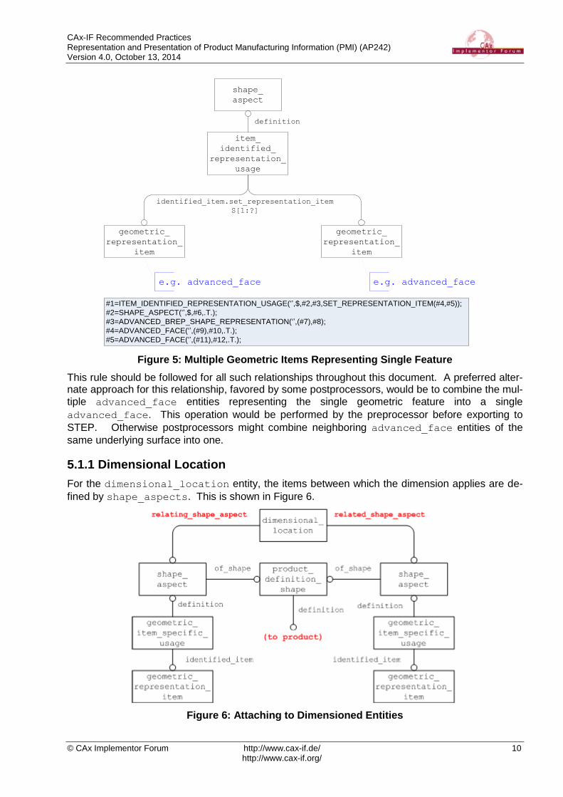
Note if a single feature is actually made up of multiple geometric_representation_item enti-
ties, the structure illustrated in Figure 5 should be used. An example use of this concept is a cylin-drical hole represented by 2 faces, where each face represents half of the cylindrical hole.
CAx-IF Recommended Practices Representation and Presentation of Product Manufacturing Information (PMI) (AP242) Version 4.0, October 13, 2014
© CAx Implementor Forum http://www.cax-if.de/ 10 http://www.cax-if.org/
shape_
aspect
geometric_
representation_
item
e.g. advanced_face
item_
identified_
representation_
usage
definition
geometric_
representation_
item
e.g. advanced_face
identified_item.set_representation_item
S[1:?]
#1=ITEM_IDENTIFIED_REPRESENTATION_USAGE(‘’,$,#2,#3,SET_REPRESENTATION_ITEM(#4,#5));
#2=SHAPE_ASPECT(‘’,$,#6,.T.);
#3=ADVANCED_BREP_SHAPE_REPRESENTATION(‘’,(#7),#8);
#4=ADVANCED_FACE(‘’,(#9),#10,.T.);
#5=ADVANCED_FACE(‘’,(#11),#12,.T.);
Figure 5: Multiple Geometric Items Representing Single Feature
This rule should be followed for all such relationships throughout this document. A preferred alter-nate approach for this relationship, favored by some postprocessors, would be to combine the mul-
tiple advanced_face entities representing the single geometric feature into a single
advanced_face. This operation would be performed by the preprocessor before exporting to
STEP. Otherwise postprocessors might combine neighboring advanced_face entities of the
same underlying surface into one.
5.1.1 Dimensional Location
For the dimensional_location entity, the items between which the dimension applies are de-
fined by shape_aspects. This is shown in Figure 6.
Figure 6: Attaching to Dimensioned Entities

CAx-IF Recommended Practices Representation and Presentation of Product Manufacturing Information (PMI) (AP242) Version 4.0, October 13, 2014
© CAx Implementor Forum http://www.cax-if.de/ 11 http://www.cax-if.org/
NOTE: this is only applicable if the shape aspects are unambiguous, otherwise refer to section 5.1.4.
NOTE: that this illustration is a change from that of the original document which can be found in
Appendix 1. It shows the use of the new geometric_item_specific_usage entity to link the
shape_aspect to the geometric_representation_item.
Note also that the same structure is applied for the specialized subtypes of Dimensional Location, namely “Dimensional Location with Path” and “Directed Dimensional Location”. The former of
these provides a “path” for the measurement to follow by means of a shape_aspect (see Figure
13), the latter provides additional semantics to the “Related” and “Relating” attributes of the
dimensional_location, i.e. The measurement is to occur from the “relating” shape aspect to
the “related” shape aspect.
Dimensions that map to a Dimensional Location are:
Dimensional Location dimensional_location.name
Curved Distance 'curved distance'
Linear Distance 'linear distance'
Table 1: Dimensional Location Types (no circular cross-section)
The values listed in Table 1 are to be used when the objects being dimensioned do not have a circular cross-section. For a dimension between objects with a circular cross-section the values in Table 2 should be used to differentiate between the desired locations. An example of this type of dimension is illustrated in Figure 7.
Figure 7: Dimensional Location Examples (with diameter)

CAx-IF Recommended Practices Representation and Presentation of Product Manufacturing Information (PMI) (AP242) Version 4.0, October 13, 2014
© CAx Implementor Forum http://www.cax-if.de/ 12 http://www.cax-if.org/
Dimensional Location dimensional_location.name
From center to outer ‘linear distance centre outer’
From center to inner ‘linear distance centre inner’
From outer to center ‘linear distance outer centre’
From outer to outer ‘linear distance outer outer’
From outer to inner ‘linear distance outer inner’
From inner to center ‘linear distance inner centre’
From inner to outer ‘linear distance inner outer’
From inner to inner 'linear distance inner inner'
Table 2: Dimensional Location Types (circular cross-section)
NOTE: By default a dimensional location between objects with a diameter is defined from each center point so the value ‘linear distance’ is used.
5.1.2 Angular Location
To define an angular dimension between 2 features, the subtype angular_location of
dimensional_location should be used. There is an additional attribute named
angle_selection that defines the measured angle as an enumeration with valid values of
.EQUAL., .LARGE. and .SMALL..
NOTE: If the specified angle is equal to or less than 180 degrees, the interpretation is direct. If the specified angle is larger than 180 degrees, the interpretation is the reflex angle.
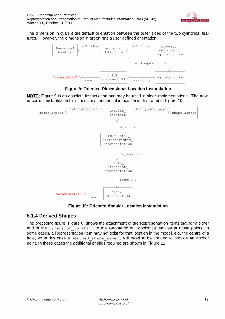
5.1.3 Oriented Dimensional Location
To define a dimensional_location in a certain orientation the structure illustrated in Figure 9
should be used. The direction defined by the x axis of the axis2_placement_3d entity is the
orientation of the dimensional_location entity. This concept is useful to distinguish between
the two dimensions illustrated below:
Figure 8: Example Oriented Dimensional Location
CAx-IF Recommended Practices Representation and Presentation of Product Manufacturing Information (PMI) (AP242) Version 4.0, October 13, 2014
© CAx Implementor Forum http://www.cax-if.de/ 13 http://www.cax-if.org/
The dimension in cyan is the default orientation between the outer sides of the two cylindrical fea-tures. However, the dimension in green has a user defined orientation.
definition
axis2_
placement_3drepresentation
dimensional_
location
items S[1:?]
used_representation
property_
definition_
representation
property_
definition
definition
name
‘orientation’
Figure 9: Oriented Dimensional Location Instantiation
NOTE: Figure 9 is an obsolete instantiation and may be used in older implementations. The new-er current instantiation for dimensional and angular location is illustrated in Figure 10.
axis2_
placement_3d
shape_
dimension_
representation
angular_
location
items S[1:?]
representation
dimensional_
characteristic_
representation
dimension
name
‘orientation’
shape_aspect shape_aspect
related_shape_aspect relating_shape_aspect
Figure 10: Oriented Angular Location Instantiation
5.1.4 Derived Shapes
The preceding figure (Figure 6) shows the attachment of the Representation Items that form either
end of the dimension_location to the Geometric or Topological entities at those points. In
some cases, a Representation Item may not exist for that location in the model, e.g. the centre of a
hole, so in this case a derived_shape_aspect will need to be created to provide an anchor
point. In these cases the additional entities required are shown in Figure 11.

CAx-IF Recommended Practices Representation and Presentation of Product Manufacturing Information (PMI) (AP242) Version 4.0, October 13, 2014
© CAx Implementor Forum http://www.cax-if.de/ 14 http://www.cax-if.org/
Figure 11: Derived Shape Aspect Instantiation
Note that this illustration is a change from that of the original document which can be found in Ap-pendix 1.
Under certain conditions, a specialized subtype of the derived_shape_aspect should be used.
These conditions are listed in Table 3. Under any other conditions, the plain derived_shape_-
aspect entity should be used. It is recommended, but not obligatory, that a meaningful string for
the type of derivation be entered in the “name” attribute of this entity.
Condition STEP Entity Used
Apex of a Cone apex
Centre of a Symmetrical Feature centre_of_symmetry
Geometric Alignment of two Features geometric_alignment
Perpendicular to Feature perpendicular_to
Spatial Extension to Feature extension
Tangential to Feature tangent
Parallel Offset from Feature parallel_offset
Table 3: Types of Derived Shape
Note the derived geometric_representation_item entities should be placed into a
constructive_geometry_representation entity. This concept is covered in the Recom-
mended Practices for Supplemental Geometry.
IMPORTANT: One area where this concept will be used frequently is dimensioning between holes or shafts and identifying locations on the surfaces to dimension between. In this case the simplest
method to use would be to define two cartesian_point entities as derived_shape_aspect
entities related to the advanced_face entities referencing the cylindrical_surface entities.
Referencing supplemental geometry in dimensions is an important concept and will be critical to ensure association of all geometric dimensions and tolerances to their respective features.

CAx-IF Recommended Practices Representation and Presentation of Product Manufacturing Information (PMI) (AP242) Version 4.0, October 13, 2014
© CAx Implementor Forum http://www.cax-if.de/ 15 http://www.cax-if.org/
5.1.5 Dimensional Size
The Dimensional Size Entity is used where the measurement only applies to one object, rather than being a measurement between two distinct geometric or topological features. Note that this
“one object” can, under certain circumstances, be a composite of several shape_aspect entities.
This will be illustrated in a later section. Figure 12 shows how a Dimensional Size Entity is at-tached to the representation object of which it is a dimension.
Figure 12: Dimensional Size Instantiation
Note that the same structure is applied for the specialized subtype of Dimensional Size, namely “Dimensional Size with Path”. This provides a “path” for the measurement to follow by means of a
shape_aspect (see Figure 13).
Dimensions that map to Dimensional Size are:
Dimensional Size dimensional_size.name
Curve Length 'curve length'
Diameter 'diameter'
Spherical Diameter ‘spherical diameter’
Radius 'radius'
Spherical Radius ‘spherical radius’
Toroidal Minor Diameter ‘toroidal minor diameter’
Toroidal Major Diameter ‘toroidal major diameter’
Toroidal Minor Radius ‘toroidal minor radius’
Toroidal Major Radius ‘toroidal major radius’
Toroidal High Major Diameter ‘toroidal high major diameter’
Toroidal Low Major Diameter ‘toroidal low major diameter’
Toroidal High Major Radius ‘toroidal high major radius’
Toroidal Low Major Radius ‘toroidal low major radius’
Thickness 'thickness'
Table 4: Dimensional Size Types

CAx-IF Recommended Practices Representation and Presentation of Product Manufacturing Information (PMI) (AP242) Version 4.0, October 13, 2014
© CAx Implementor Forum http://www.cax-if.de/ 16 http://www.cax-if.org/
5.1.6 Angular Size
To define an angular dimension on a single feature, the subtype angular_size of dimen-
sional_size should be used. There is an additional attribute named angle_selection that
defines the measured angle as an enumeration with valid values of .EQUAL., .LARGE. and
.SMALL..
NOTE: If the specified angle is equal to or less than 180 degrees, the interpretation is direct. If the specified angle is larger than 180 degrees, the interpretation is the reflex angle.
5.1.7 Dimensional Location/Size with Path
For some measurements, a path for the measurement needs to be defined, for example, when measuring the linear distance between two points on a curved surface. In this case, the meas-urement would need to follow the curve of the surface and not be the shortest straight line distance between the two points. In order to convey this information, this specialized subtype has an addi-
tional attribute, “path”, which points to a shape_aspect defining the path the measurement is to
take. The instantiation of this is shown in Figure 13.
Figure 13: Dimension With Path Instantiation
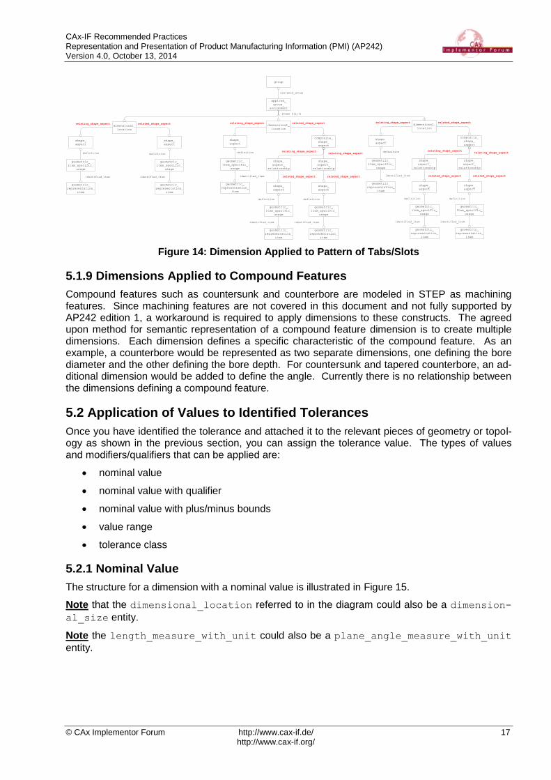
5.1.8 Dimension Applied to Pattern of Tabs/Slots
The instance diagram for how to apply a dimension to a pattern of tabs/slots is illustrated below in Figure 14.
CAx-IF Recommended Practices Representation and Presentation of Product Manufacturing Information (PMI) (AP242) Version 4.0, October 13, 2014
© CAx Implementor Forum http://www.cax-if.de/ 17 http://www.cax-if.org/
shape_
aspect
dimensional_
location
shape_
aspect
relating_shape_aspect related_shape_aspect
geometric_
item_specific_
usage
definition
geometric_
item_specific_
usage
definition
geometric_
representation_
item
identified_item
geometric_
representation_
item
identified_item
shape_
aspect
geometric_
item_specific_
usage
definition
geometric_
representation_
item
identified_item
composite_
shape_
aspect
shape_
aspect_
relationship
shape_
aspect_
relationship
relating_shape_aspectrelating_shape_aspect
related_shape_aspect related_shape_aspect
shape_
aspect
dimensional_
location
shape_
aspect
relating_shape_aspect related_shape_aspect
geometric_
item_specific_
usage
definition
geometric_
item_specific_
usage
definition
geometric_
representation_
item
identified_item
geometric_
representation_
item
identified_item
applied_
group_
assignment
items S[1:?]
group
assigned_group
Figure 14: Dimension Applied to Pattern of Tabs/Slots
5.1.9 Dimensions Applied to Compound Features
Compound features such as countersunk and counterbore are modeled in STEP as machining features. Since machining features are not covered in this document and not fully supported by AP242 edition 1, a workaround is required to apply dimensions to these constructs. The agreed upon method for semantic representation of a compound feature dimension is to create multiple dimensions. Each dimension defines a specific characteristic of the compound feature. As an example, a counterbore would be represented as two separate dimensions, one defining the bore diameter and the other defining the bore depth. For countersunk and tapered counterbore, an ad-ditional dimension would be added to define the angle. Currently there is no relationship between the dimensions defining a compound feature.
5.2 Application of Values to Identified Tolerances
Once you have identified the tolerance and attached it to the relevant pieces of geometry or topol-ogy as shown in the previous section, you can assign the tolerance value. The types of values and modifiers/qualifiers that can be applied are:
nominal value
nominal value with qualifier
nominal value with plus/minus bounds
value range
tolerance class
5.2.1 Nominal Value
The structure for a dimension with a nominal value is illustrated in Figure 15.
Note that the dimensional_location referred to in the diagram could also be a dimension-
al_size entity.
Note the length_measure_with_unit could also be a plane_angle_measure_with_unit
entity.

CAx-IF Recommended Practices Representation and Presentation of Product Manufacturing Information (PMI) (AP242) Version 4.0, October 13, 2014
© CAx Implementor Forum http://www.cax-if.de/ 18 http://www.cax-if.org/
dimension
measure_ representation_ item &&
representation_ item &&
measure_with_unit &&
length_measure_with_unit
shape_
dimension_
representation
dimensional_
location
items S[1:?]
representation
dimensional_
characteristic_
representation
Figure 15: Nominal Value Instantiation
The name attribute in shape_dimension_representation carries significance in its value as
defined below in Table 5 for the tolerance principle used.
Tolerance Principle shape_dimension_representation.name
Independency (ASME) [ ] ‘independency’
Envelope Requirement (ISO) [ ] ‘envelope requirement’
Use default as specified in section 4 ‘’ (empty string)
Table 5: Tolerance Principle
5.2.2 Nominal Value with Qualifier
In this case, a nominal value is applied to the dimension, i.e. A set value for the measurement, without any tolerance bounds. However, the value can be limited as to whether it is a Maximum value or Minimum Value. There may be other limits allowed, and as the limit maps to a String in the Part21 Instantiation, there is no restriction on what value can be entered. An example of this type of dimension is illustrated below:
Figure 16: Example Nominal Value with Qualifier
The entity used to apply a qualifier to a dimension value is type_qualifier and it has a single
attribute of type string as illustrated in Figure 17. A qualified_representation_item is re-
quired to reference this new entity.
Note the dimensional_location referred to in the diagram could also be a dimen-
sional_size entity.
Note the length_measure_with_unit referred to in the diagram could also be a plane_an-
gle_measure_with_unit entity.

CAx-IF Recommended Practices Representation and Presentation of Product Manufacturing Information (PMI) (AP242) Version 4.0, October 13, 2014
© CAx Implementor Forum http://www.cax-if.de/ 19 http://www.cax-if.org/
dimension
measure_ representation_ item &&
qualified_ representation_ item &&
measure_with_unit &&
length_measure_with_unit &&
representation_item
shape_
dimension_
representation
dimensional_
location
items S[1:?]
representation
dimensional_
characteristic_
representation
type_
qualifier
qualifiers
S[1:?] name
Figure 17: Nominal Value with Qualifier Instantiation
The types of qualifiers and the valid values for the name attribute are illustrated in Table 6.
Value Qualifier type_qualifier.name
Maximum Value ‘maximum’
Minimum Value ‘minimum’
Average Value ‘average’
Table 6: Value Qualifiers
5.2.3 Nominal Value with Plus/Minus Bounds
If a tolerance is represented as a Nominal value with a set of plus and minus deviations or bounds to that tolerance, then the entities shown in Figure 19 are used to instantiate the STEP file. An example of this type of dimension is illustrated below:
Figure 18: Example Nominal Value with Plus/Minus Bounds

CAx-IF Recommended Practices Representation and Presentation of Product Manufacturing Information (PMI) (AP242) Version 4.0, October 13, 2014
© CAx Implementor Forum http://www.cax-if.de/ 20 http://www.cax-if.org/
dimension
measure_ representation_item &&
representation_item &&
measure_with_unit &&
length_measure_with_unit
shape_
dimension_
representation
dimensional_
location
items S[1:?]
representation
dimensional_
characteristic_
representation
plus_minus_
tolerance
tolerance_
value
measure_
with_unit
measure_
with_unit
toleranced_dimension
range
lower_bound upper_bound
Figure 19: Nominal Value with Plus/Minus Bounds Instantiation
The values of the plus/minus tolerance are found in the measure_with_unit entities referred to
by the “upper” and “lower” attributes of the tolerance_value entity.
Note that for clarity, even though it is given that the tolerance_value is an upper or lower limit,
the value should still be given as an offset from the nominal. E.g. the lower limit should usually be a negative number and the upper limit a positive number.
Note that it is possible to have two positive numbers or two negative numbers (see part 47 section 6.5.3).
5.2.4 Value Range
An alternative way of presenting, rather than representing the dimension, is as a range of values that is the extents of the tolerance applied. As originally mapped in the Standard, this would give two values, one for the upper limit and one for the lower limit. Upon implementation, however, it was found that the majority of CAD systems hold the tolerance value as a nominal, with a plus/minus deviation, and handle the presentation of this data separately, thus the lack of a nomi-nal value through this method caused problems for re-importing the data, as this value was lost. In order to alleviate this, a third value, representing the nominal value was added to the mapping. An example of this type of dimension is illustrated below:
Figure 20: Example Value Range
The STEP instantiation of this is shown in Figure 21.

CAx-IF Recommended Practices Representation and Presentation of Product Manufacturing Information (PMI) (AP242) Version 4.0, October 13, 2014
© CAx Implementor Forum http://www.cax-if.de/ 21 http://www.cax-if.org/
dimension
shape_
dimension_
representation
dimensional_
location
Items
S[1:?]
representation
dimensional_
characteristic_
representation
measure_ representation_item &&
representation_item &&
measure_with_unit &&
length_measure_with_unit
measure_ representation_item &&
representation_item &&
measure_with_unit &&
length_measure_with_unit
measure_ representation_item &&
representation_item &&
measure_with_unit &&
length_measure_with_unit
name‘upper limit
name‘nominal value’
name‘lower limit
Figure 21: Value Range Instatiation
To determine which of the measure_representation_items denotes which value, they shall
be identified by one of the following strings used for the representation_item.name attribute:
“nominal value”, “upper limit”, and “lower limit”.
5.2.5 Tolerance Class
An example of a tolerance class dimension is illustrated below:
Figure 22: Example Tolerance Class
The implementation of this type of dimension uses the limits_and_fits entity as illustrated in
Figure 23. The form_variance attribute represents the fundamental deviation or "position letter"
of the ISO 286 limits-and-fits tolerance classification. Only symbols defined in ISO 286 shall be provided. The symbols “A” to “ZC” for holes or “a” to “zc” for shafts may be used to classify devia-
tion. The zone_variance attribute represents the kind of fitting to which the tolerance applies.
The value of this attribute need not be specified. Normally the tolerance applies to an external or internal feature. Where applicable the following values shall be used:
"hole": the tolerance applies to an internal feature
"shaft": the tolerance applies to an external feature
Whether the tolerance applies to an interior or exterior feature can be determined from the position
letter of the fundamental deviation, therefore zone_variance need not be specified. The grade
attribute represents the quality or the accuracy grade of a tolerance. Only symbols defined in ISO
286 shall be provided. The grade is one of the 18 international standard tolerance grades defined
in ISO 286. The source attribute is not populated at this time.
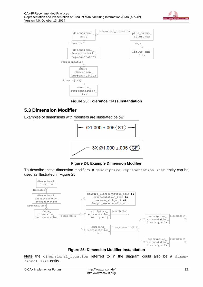
CAx-IF Recommended Practices Representation and Presentation of Product Manufacturing Information (PMI) (AP242) Version 4.0, October 13, 2014
© CAx Implementor Forum http://www.cax-if.de/ 22 http://www.cax-if.org/
dimension
measure_
representation_
item
shape_
dimension_
representation
dimensional_
size
items S[1:?]
representation
dimensional_
characteristic_
representation
plus_minus_
tolerance
limits_and_
fits
toleranced_dimension
range
Figure 23: Tolerance Class Instantiation
5.3 Dimension Modifier
Examples of dimensions with modifiers are illustrated below:
Figure 24: Example Dimension Modifier
To describe these dimension modifiers, a descriptive_representation_item entity can be
used as illustrated in Figure 25.
dimension
shape_
dimension_
representation
dimensional_
location
representation
dimensional_
characteristic_
representation
measure_representation_item &&
representation_item &&
measure_with_unit &&
length_measure_with_unit
descriptive_
representation_
item (type 1)
description
items S[1:?]
compound_
representation_
item
item_element L[1:?]
descriptive_
representation_
item (type 2)
description
descriptive_
representation_
item (type 2)
description
Figure 25: Dimension Modifier Instantiation
Note the dimensional_location referred to in the diagram could also be a dimen-
sional_size entity.

CAx-IF Recommended Practices Representation and Presentation of Product Manufacturing Information (PMI) (AP242) Version 4.0, October 13, 2014
© CAx Implementor Forum http://www.cax-if.de/ 23 http://www.cax-if.org/
Note the length_measure_with_unit referred to in the diagram could also be a plane_an-
gle_measure_with_unit entity.
Note representation_item.name should be set to ‘dimensional note’
As you may notice, there are two types of modifiers used for dimensions, the first type is limited to
the kind of dimension it is. There can be only one descriptive_representation_item (type
1) entity associated with a dimension. The types of modifiers and valid values for the type 1 de-scription attribute are shown in Table 7.
Dimension Modifier (type 1) descriptive_representation_
item.description
Basic (ASME) / Theoretical (ISO) ‘theoretical’
Reference (ASME) / Auxiliary (ISO) ‘auxiliary’
Table 7: Dimension Modifiers (type 1)
There can be multiple type 2 modifiers associated with a single dimension so the
compound_representation_item entity is used to group them. The types of modifiers and
valid values for the type 2 description attribute are shown in Table 8.
Dimension Modifier (type 2) Symbol descriptive_representation_
item.description
Controlled Radius CR ‘controlled radius’
Square ‘square’
Statistical Tolerance ‘statistical’
Continuous Feature ‘continuous feature’
Two Point Size 'two point size'
Local size defined by a sphere 'local size defined by a sphere'
Least-squares association criterion 'least squares association criteria'
Maximum inscribed association criterion
'maximum inscribed association criteria'
Minimum circumscribed association criterion
'minimum circumscribed association criteria'
Circumference diameter (calculated size)
'circumference diameter calculated size'
Area diameter (calculated size) 'area diameter calculated size'
Volume diameter (calculated size) 'volume diameter calculated size'

CAx-IF Recommended Practices Representation and Presentation of Product Manufacturing Information (PMI) (AP242) Version 4.0, October 13, 2014
© CAx Implementor Forum http://www.cax-if.de/ 24 http://www.cax-if.org/
Dimension Modifier (type 2) Symbol descriptive_representation_
item.description
Maximum size 'maximum rank order size'
Minimum size 'minimum rank order size'
Average size 'average rank order size'
Median size 'median rank order size'
Mid-range size 'mid range rank order size'
Range of sizes 'range rank order size'
Any restricted portion of feature 'any part of the feature'
Any cross section 'any cross section'
Specific fixed cross section 'specific fixed cross section'
Common tolerance 'common tolerance'
Free-state condition 'free state condition'
Between Not a modifier, see section 6.4.3
Table 8: Dimension Modifiers (type 2)
5.4 Applying Number of Decimal Places
The displayed value of the Dimensional Tolerance can be truncated to a number of decimal plac-es, by specifying a Value Format Type Qualifier to the Representation Item which holds the toler-
ance value. This is done using a complex entity for the measure_representation_item, con-
taining the qualified_representation_item entity, which in turn, points to a
value_format_type_qualifier, which specifies the number of places to the right and left of
the decimal point by its format_type attribute.

CAx-IF Recommended Practices Representation and Presentation of Product Manufacturing Information (PMI) (AP242) Version 4.0, October 13, 2014
© CAx Implementor Forum http://www.cax-if.de/ 25 http://www.cax-if.org/
dimension
measure_ representation_item &&
qualified_ representation_item &&
measure_with_unit &&
plane_angle_measure_with_unit &&
representation_item
shape_
dimension_
representation
dimensional_
location
items S[1:?]
representation
dimensional_
characteristic_
representation
value_format_type_qualifier
qualifiers
S[1:?]
format_type
‘NR2 x.y’
‘NR2S x.y’
Figure 26: Decimal Places
The values for x and y in Figure 26 specify the number of places to the left and right of the decimal point respectively. A typical value would be ‘NR2 2.2’.
6 Implementation Guidelines for GD&T Representation
6.1 Associating Tolerances with Features
In STEP, the tolerance entities are associated with a shape_aspect that identifies the toleranced
feature. The feature is identified by a shape_aspect which has a representation. In the case of a
solid boundary representation model, the feature of the part is represented by one or more
topological_representation_items such as advanced_face entities. For example, a
through hole in a solid model might be represented by two semi-circular surfaces, each an
advanced_face entity. These topological_representation_items are collected together
by a shape_representation which is representation of the shape_aspect for the feature.
This shape_representation shall share the same geometric_representation_context
as the solid. See Figure 27 for an example of how the tolerance entities are related to the shape elements of the toleranced feature.

CAx-IF Recommended Practices Representation and Presentation of Product Manufacturing Information (PMI) (AP242) Version 4.0, October 13, 2014
© CAx Implementor Forum http://www.cax-if.de/ 26 http://www.cax-if.org/
Figure 27: Defining Toleranced Features using Shape_Aspect
Part 21 Example
#187=ADVANCED_FACE('feature face',(#181),#186,.T.);
#252=PRODUCT_DEFINITION_SHAPE('',$,#17);
#315=SHAPE_ASPECT('',$,#252,.T.);
#316=GEOMETRIC_ITEM_SPECIFIC_USAGE(‘’,’flatness tolerance face’,
#315, #199, #187);
#320=FLATNESS_TOLERANCE('#320',$,#319,#315);
6.2 Associating Tolerances with Dimensions
Instead of referencing a shape_aspect entity, a tolerance may reference a
dimensional_location entity or a dimensional_size entity to represent the concept illus-
trated below:
Figure 28: Example Tolerance with Dimension
6.3 Associating Tolerances with Part (All-Over)
To support the concept of all-over as illustrated below, a product_definition_shape entity
may be referenced from a geometric_tolerance entity instead of the shape_aspect entity.
Figure 29: Example Tolerance with Part (all-over)
6.4 Associating Tolerances with Multiple Features
There are many cases where a Tolerance or Datum needs to be associated with more than one feature, for example, when a face based on the datum geometry has been split by a slot or other feature. In these cases, the associated features are combined under a
composite_group_shape_aspect. Figure 30 shows the STEP Entities required to implement

CAx-IF Recommended Practices Representation and Presentation of Product Manufacturing Information (PMI) (AP242) Version 4.0, October 13, 2014
© CAx Implementor Forum http://www.cax-if.de/ 27 http://www.cax-if.org/
this functionality. In order to distinguish this case from the “Pattern of Features” case (see below),
the name attribute of the composite_group_shape_aspect shall be set to the string “multiple
elements”.
relating_shape_aspect
relating_shape_aspect
related_shape_aspect
geometric_
item_specific_
usage
definition
geometric_
representation_
item
identified_item
shape_aspect_
relationship
shape_
aspect
composite_
group_
shape_
aspect
shape_
aspect
related_shape_aspect
geometric_
item_specific_
usage
definition
geometric_
representation_
item
identified_item
shape_aspect_
relationship
characterized_
definition
of_shape
Tolerance
Information
e.g. datum or
FCF
Figure 30: Multiple Feature Construct
Part 21 Example
#10341=PRODUCT_DEFINITION_SHAPE('',$,#17);
#10396=SHAPE_ASPECT('',$,#10341,.T.);
#10403=GEOMETRIC_ITEM_SPECIFIC_USAGE(‘’, ‘single feature’, #10396,
#5500, #5423);
#10400=SHAPE_ASPECT('',$,#10341,.T.);
#10403=GEOMETRIC_ITEM_SPECIFIC_USAGE(‘’, ‘single feature’, #10400,
#5500, #5411);
#10404=COMPOSITE_GROUP_SHAPE_ASPECT(‘’,'multiple elements',
#10341,.T.);
#10405=SHAPE_ASPECT_RELATIONSHIP('',$,#10404,#10396);
#10406=SHAPE_ASPECT_RELATIONSHIP('',$,#10404,#10400);
6.4.1 Associating tolerances with a Pattern of Features
One of the uses of the Multiple Feature construct is allowing the exchange of Tolerances applied to a pattern of features. In order to differentiate this from the normal case, the string “pattern of
features” is used to populate the composite_group_shape_aspect.description attribute.
e.g. #299=COMPOSITE_GROUP_SHAPE_ASPECT('','pattern of features',#246,.T.);

CAx-IF Recommended Practices Representation and Presentation of Product Manufacturing Information (PMI) (AP242) Version 4.0, October 13, 2014
© CAx Implementor Forum http://www.cax-if.de/ 28 http://www.cax-if.org/
6.4.2 Applying All Around Modifier
There is a subtype of the composite_shape_aspect entity called all_around_shape-
_aspect which can be used to represent the concept illustrated below:
Figure 31: Example Tolerance with All Around Modifier
6.4.3 Applying Between Modifier
There is another subtype of the composite_shape_aspect entity called
between_shape_aspect which is used to convey the concept illustrated below:
Figure 32: Example Tolerance with Between Modifier
A sample instantiation of this construct is illustrated in Figure 33. The approach in general is to not relay the instructions “from here to here”, but to define the resulting restricted area. The start and end features may be given in addition when they apply. The start and end features defined by the
geometric_representation_item would typically be an edge_curve but could be an
advanced_face. Other implementations could reference supplemental geometry to define the
start and end features. To define the restricted area and to satisfy the case when the affected ar-
ea spans multiple faces, the connected_face_set is used. The final implementation of the be-
tween modifier is dependent on the CAD system representation.
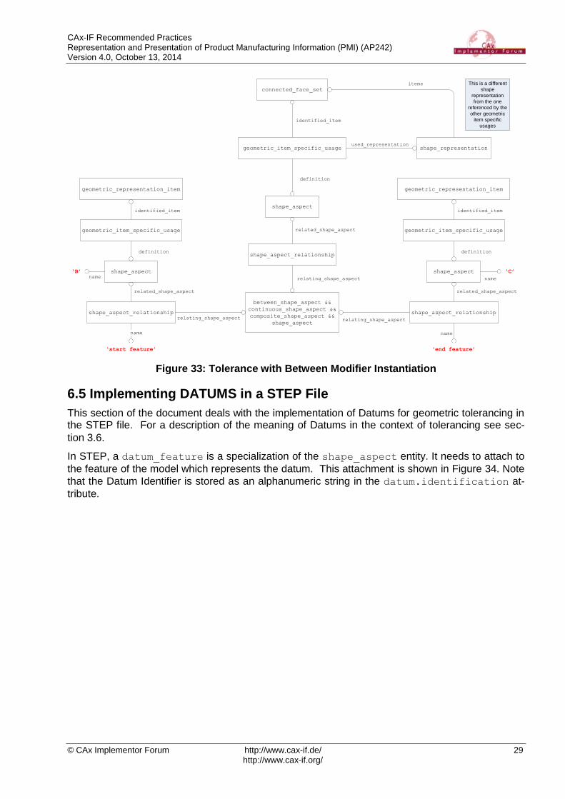
CAx-IF Recommended Practices Representation and Presentation of Product Manufacturing Information (PMI) (AP242) Version 4.0, October 13, 2014
© CAx Implementor Forum http://www.cax-if.de/ 29 http://www.cax-if.org/
between_shape_aspect &&
continuous_shape_aspect &&
composite_shape_aspect &&
shape_aspect
shape_aspect_relationshiprelating_shape_aspect
shape_aspect_relationship
relating_shape_aspect
shape_aspect
related_shape_aspect
name
‘start feature’
name
‘end feature’
geometric_item_specific_usage
definition
geometric_representation_item
identified_item
shape_aspect
related_shape_aspect
geometric_item_specific_usage
definition
geometric_representation_item
identified_item
name
‘B’
name
‘C’
geometric_item_specific_usage
definition
connected_face_set
identified_item
shape_aspect_relationship
relating_shape_aspect
shape_aspect
related_shape_aspect
shape_representationused_representation
This is a different
shape
representation
from the one
referenced by the
other geometric
item specific
usages
items
Figure 33: Tolerance with Between Modifier Instantiation
6.5 Implementing DATUMS in a STEP File
This section of the document deals with the implementation of Datums for geometric tolerancing in the STEP file. For a description of the meaning of Datums in the context of tolerancing see sec-
tion 3.6.
In STEP, a datum_feature is a specialization of the shape_aspect entity. It needs to attach to
the feature of the model which represents the datum. This attachment is shown in Figure 34. Note
that the Datum Identifier is stored as an alphanumeric string in the datum.identification at-
tribute.
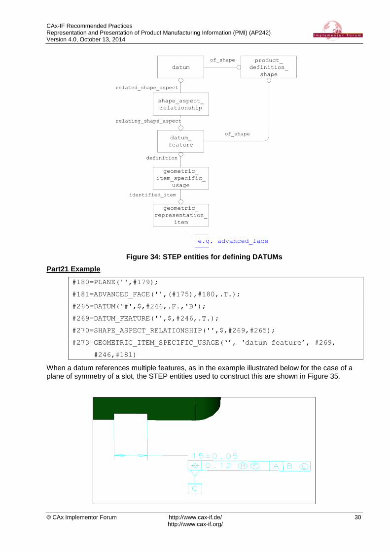
CAx-IF Recommended Practices Representation and Presentation of Product Manufacturing Information (PMI) (AP242) Version 4.0, October 13, 2014
© CAx Implementor Forum http://www.cax-if.de/ 30 http://www.cax-if.org/
datum
datum_
feature
geometric_
item_specific_
usage
definition
geometric_
representation_
item
identified_item
shape_aspect_
relationship
e.g. advanced_face
related_shape_aspect
relating_shape_aspect
product_
definition_
shape
of_shape
of_shape
Figure 34: STEP entities for defining DATUMs
Part21 Example
#180=PLANE('',#179);
#181=ADVANCED_FACE('',(#175),#180,.T.);
#265=DATUM('#',$,#246,.F.,'B');
#269=DATUM_FEATURE('',$,#246,.T.);
#270=SHAPE_ASPECT_RELATIONSHIP('',$,#269,#265);
#273=GEOMETRIC_ITEM_SPECIFIC_USAGE(‘’, ‘datum feature’, #269,
#246,#181)
When a datum references multiple features, as in the example illustrated below for the case of a plane of symmetry of a slot, the STEP entities used to construct this are shown in Figure 35.

CAx-IF Recommended Practices Representation and Presentation of Product Manufacturing Information (PMI) (AP242) Version 4.0, October 13, 2014
© CAx Implementor Forum http://www.cax-if.de/ 31 http://www.cax-if.org/
datum
datum_feature
item_identified_
representation_
usage
geometric_
representation_
item
shape_aspect_
relationship
related_shape_aspect
relating_shape_aspect
product_
definition_
shape
of_shape
of_shape
geometric_
representation_
item
identified_item
shape_aspect_
deriving_
relationship
centre_of_
symmetry
relating_shape_aspect
tolerance
geometric_
item_specific_
usage
identified_item
geometric_
item_specific_
usage
identified_item
shape_aspect
definition
shape_aspect
definition
dimensional_location
related_shape_aspect
Figure 35: DATUM referencing mulitple features
Another case when a datum is represented by multiple features is illustrated below by a pattern of features forming a group. The STEP entities used to construct this are show in Figure 36.

CAx-IF Recommended Practices Representation and Presentation of Product Manufacturing Information (PMI) (AP242) Version 4.0, October 13, 2014
© CAx Implementor Forum http://www.cax-if.de/ 32 http://www.cax-if.org/
Figure 36: DATUM defined by group of features
6.6 Implementing DATUM TARGETS in a STEP File
A Datum Target is a point, line or limited area of the part surface that is used in the construction of a Datum, when it is not practical to use neither an entire feature nor a substantial region. A Datum is constructed from one or more Datum Targets, and may be offset from the part surface. The im-
plementation of Datum Targets is done by relating the placed_datum_target_feature to the
Datum of which it is part of the definition, by means of a shape_aspect_relationship. This is
shown in Figure 37.

CAx-IF Recommended Practices Representation and Presentation of Product Manufacturing Information (PMI) (AP242) Version 4.0, October 13, 2014
© CAx Implementor Forum http://www.cax-if.de/ 33 http://www.cax-if.org/
datum
axis2_
placement_3d
placed_datum_
target_feature
definition
measure_representation_item &&
measure_with_unit &&
length_measure_with_unit &&
representation_item
items S[1:?]
shape_aspect_
relationship
related_shape_aspect
relating_shape_aspect
property_
definition
shape_
definition_
representation
shape_
representation_
with_parameters
definition
used_representation
Figure 37: Datum Target Instantiation
The identification of the Datum Target is stored in the placed_datum_target_-
feature.target_id attribute.
Note to avoid confusion and duplication only the numeric portion of the identification is stored here, i.e. For Datum Target “A1”, store the string “1”. This means the letter portion of the Datum
Target, i.e. “A”, is stored in the datum.identification attribute.
Note that due to the rules defined for placed_datum_target_feature using the function
get_shape_aspect_property_definition_representations it is not possible to update
the linkage between the shape_aspect and the geometry using geometric_item_-
specific_usage.
Note the path from the placed_datum_target_feature entity to the shape_represen-
tation_with_parameters entity must be resolvable. This means there is a one-to-one rela-
tionship between these entities preventing any ambiguity when post-processing.
Note the context_of_items attribute of the shape_representation_with_parameters
entity must reference the same context as the shape representation associated with the product definition.

CAx-IF Recommended Practices Representation and Presentation of Product Manufacturing Information (PMI) (AP242) Version 4.0, October 13, 2014
© CAx Implementor Forum http://www.cax-if.de/ 34 http://www.cax-if.org/
Part21 Example
#277=DATUM('',$,#252,.F.,'A');
#278=PLACED_DATUM_TARGET_FEATURE('','circle',#252,.T.,'1');
#279=SHAPE_ASPECT_RELATIONSHIP('','datum target',#277,#278);
#280=PROPERTY_DEFINITION('',$,#278);
#281=CARTESIAN_POINT('',(1.0,2.0,0.5));
#282=DIRECTION('',(1.0,0.0,0.0));
#283=DIRECTION('',(0.0,0.0,1.0));
#284=AXIS2_PLACEMENT_3D('',#281,#283,#282);
#285=(LENGTH_MEASURE_WITH_UNIT()MEASURE_REPRESENTATION_ITEM()
REPRESENTATION_ITEM('target diameter')
MEASURE_WITH_UNIT(LENGTH_MEASURE(0.75), #6));
#286=SHAPE_REPRESENTATION_WITH_PARAMETERS('',(#284,#285),#246);
#287=SHAPE_DEFINITION_REPRESENTATION(#280,#286);
6.6.1 DATUM TARGET types
The particular geometric representation that forms the Datum Target is defined by the shape rep-
resentation with parameters, as well as by the placed_datum_target_feature.descrip-
tion field. The allowable values for this are:
point
line
rectangle
circle
area
Each of these requires particular representation items, complete with pre-defined strings, in the
shape_representation_with_parameters that conveys the target area. The table below
defines the relevant entities and values required.
Target Type Representation Entities
Point A placement entity (A2PL3D) with a name of “orientation”. The “Z” axis of
the placement denotes the normal of the surface pointing away from the material.
Line A placement entity (A2PL3D) with a name of “orientation” plus a complex
instance of measure_representation_item and
length_measure_with_unit entities with a name of “target length”
denoting the length along the “X” axis of the placement. The “Z” axis of the placement denotes the normal of the surface pointing away from the material.

CAx-IF Recommended Practices Representation and Presentation of Product Manufacturing Information (PMI) (AP242) Version 4.0, October 13, 2014
© CAx Implementor Forum http://www.cax-if.de/ 35 http://www.cax-if.org/
Target Type Representation Entities
Rectangle A placement entity (A2PL3D) with a name of “orientation” plus two com-
plex instances of measure_representation_item and
length_measure_with_unit entities with names of “target length”
and “target width”. The length is along the placement “X” axis and the width along the derived “Y” axis, with the placement itself positioned at the centre of the rectangle. The “Z” axis of the placement denotes the normal of the surface pointing away from the material.
Circle A placement entity (A2PL3D) with a name of “orientation” plus a complex
instance of measure_representation_item and
length_measure_with_unit entities with a name of “target diameter”.
The “Z” axis of the placement denotes the normal to the surface pointing away from the material.
Area Requires a different instantiation from Figure 37 and as illustrated below in Figure 38
Table 9: Instantiation of DATUM TARGET types
datum
datum_target
shape_aspect_
relationship
related_shape_aspect
relating_shape_aspect
description
area
identified_item
geometric_
representation_
item
e.g. advanced_face
geometric_
item_specific_
usage
definition
Figure 38: Area Datum Target
6.6.2 Relating Datum Target to Feature
To relate a datum target to a feature the structure illustrated in Figure 39 should be used. Note
there should be at most one feature_for_datum_target_relationship entity referencing a
placed_datum_target_feature entity.

CAx-IF Recommended Practices Representation and Presentation of Product Manufacturing Information (PMI) (AP242) Version 4.0, October 13, 2014
© CAx Implementor Forum http://www.cax-if.de/ 36 http://www.cax-if.org/
shape_
aspect
identified_item
geometric_
representation_
item
e.g. advanced_face
placed_datum_
target_feature
feature_for_
datum_target_
relationship
relating_shape_aspect
related_shape_aspect
geometric_
item_specific_
usage
definition
Figure 39: Relating Datum Target to Feature
6.6.3 Movable Datum Target
An example of a movable datum target is illustrated below:
Figure 40: Example Movable Datum Target
A direction entity is used with a string value of “movable direction” for the direction.name
attribute to indicate the datum target is movable. This direction entity would be included in the
set of items in the shape_representation_with_parameters entity.
6.7 Feature Control Frames
This section defines the instantiation requirements for the Feature Control Frames which define the Geometric Tolerance. A Feature Control Frame takes the form shown in Figure 41 below, in order to define the type and value of the tolerance that has been applied to the feature.
Figure 41: Feature Control Frame

CAx-IF Recommended Practices Representation and Presentation of Product Manufacturing Information (PMI) (AP242) Version 4.0, October 13, 2014
© CAx Implementor Forum http://www.cax-if.de/ 37 http://www.cax-if.org/
Reading from left to right, Figure 41 shows:
In the first box, the type of the tolerance, in this case, a position tolerance. See Table 10 for the full list of tolerance types supported.
The second box defines the tolerance value itself (0.1) along with any tolerance modifiers.
The third and subsequent boxes specify datum references along with any datum modifiers.
6.8 STEP Supported Tolerance Types
The following table shows the Geometric Tolerance types supported by STEP. The table lists the tolerance name, the STEP entity which is used to represent it, and additionally any restrictions on the number of datum references that apply in the STEP schema to that tolerance type.
Tolerance type STEP Entity Datums
Angularity angularity_tolerance 1, 2 or 3
Circular Runout circular_runout_tolerance 1, 2 or 3
Circularity / Roundness roundness_tolerance None
Coaxiality coaxiality_tolerance 1, 2 or 3
Concentricity concentricity_tolerance 1, 2 or 3
Cylindricity cylindricity_tolerance None
Flatness flatness_tolerance None
Parallelism parallelism_tolerance 1, 2 or 3
Perpendicularity perpendicularity_tolerance 1, 2 or 3
Position position_tolerance None, 1, 2 or 3
Profile of a Line line_profile_tolerance None, 1, 2 or 3
Profile of a Surface surface_profile_tolerance None, 1, 2 or 3
Straightness straightness_tolerance None
Symmetry symmetry_tolerance 1, 2 or 3
Total Runout total_runout_tolerance 1, 2 or 3
Table 10: Supported Tolerance Types
6.9 Implementing Feature Control Frames
The STEP file implementation of the Geometric Tolerances makes use of the entities shown in the sections below, each section showing the entities required for the different cases, i.e. tolerance without modifiers or datums, tolerance with datums and modified tolerances. Note that the linkage to the Feature(s) being toleranced is covered in Figure 30 and Figure 34.
NOTE: All geometry_tolerance entities have an optional attribute named description to be
used for text associated with the tolerance otherwise not covered by a semantic value or modifier.

CAx-IF Recommended Practices Representation and Presentation of Product Manufacturing Information (PMI) (AP242) Version 4.0, October 13, 2014
© CAx Implementor Forum http://www.cax-if.de/ 38 http://www.cax-if.org/
6.9.1 Geometric Tolerance without Modifiers or Datums
This case can only occur for the following Tolerance types:
Circularity (Roundness)
Cylindricity
Flatness
Position
Profile of a Line
Profile of a Surface
Straightness
For this example, we will show a Position Tolerance. The length_measure_with_unit entity is
used to convey the Tolerance Value.
Figure 42: Tolerance without Modification or Datums
Part21 Example
#274=LENGTH_MEASURE_WITH_UNIT(LENGTH_MEASURE(0.1),#4);
#277=POSITION_TOLERANCE('',$,#274,#264);
6.9.2 Tolerance Zone
The entities tolerance_zone and tolerance_zone_form may be used to convey additional
information about the tolerance value. Figure 43 illustrates how these entities are used in relation-
ship with a geometric tolerance entity, i.e. position_tolerance.
length_
measure_
with_unit
position_
tolerance
magnitude
tolerance_zone
tolerance_
zone_form
form
defining_tolerance
name
Figure 43: Tolerance Zone
Examples of the types of tolerances with special symbols are illustrated below:
Figure 44: Example Tolerance Zones
The valid values for the name attribute in these cases are illustrated in Table 11.

CAx-IF Recommended Practices Representation and Presentation of Product Manufacturing Information (PMI) (AP242) Version 4.0, October 13, 2014
© CAx Implementor Forum http://www.cax-if.de/ 39 http://www.cax-if.org/
Tolerance Zone tolerance_zone_form.name
Diameter [ ] ‘cylindrical or circular’
Spherical Diameter [ ] ‘spherical’
Table 11: Tolerance Zones with Associated Symbols
There are many more types of tolerance zones, but none actually have a special symbol associat-
ed with it. Other string values may be used for the name attribute to convey additional information
if required or the string may be empty. The complete table of valid strings for tolerance zones is listed in Table 12. Examples of other tolerance zones are illustrated below in Figure 45.
tolerance_zone_form.name
‘within a circle’
'between two concentric circles'
'between two equidistant curves'
'within a cylinder'
‘between two coaxial cylinders’
'between two equidistant surfaces'
'non uniform'
'unknown'
Table 12: Other Tolerance Zones
NOTE: Unless otherwise specified, the attribute tolerance_zone_form.name should have a
value of ‘unknown’ when not defined by geometry or known by the user.
straightness_
tolerancetolerance_zone
tolerance_
zone_form
form
defining_tolerance
symmetric_
shape_aspect
toleranced_shape_aspect
length_
measure_
with_unit
magnitude
geometric_item_
specific_usage
advanced_facefeature being
toleranced
cylindrical_
surface
shape_aspect_
deriving_
relationsip
related_shape_aspect
relating_shape_aspect
centre_of_
symmetry
name
‘within a cylinder’

CAx-IF Recommended Practices Representation and Presentation of Product Manufacturing Information (PMI) (AP242) Version 4.0, October 13, 2014
© CAx Implementor Forum http://www.cax-if.de/ 40 http://www.cax-if.org/
Figure 45: Other Tolerance Zones
6.9.2.1 Affected Plane Tolerance Zone
Some tolerance zones are defined by orientation planes or intersection planes. An example of an intersection plane used to define a tolerance zone is illustrated below:
Figure 46: Example Affected Plane Tolerance Zone
The shape_aspect_relationship entity is used to convey this concept as illustrated in Figure
47. The description attribute value should contain the string value of “affected plane association”.
The affected plane is defined by the perpendicular intersection of the line element with the feature being toleranced.
runout_
tolerancetolerance_zone
tolerance_
zone_form
form
defining_
tolerance
runout_zone_
definitionzone
plane_angle_
measure_
with_unit
orientation
shape_aspect
toleranced_shape_aspect
length_
measure_
with_unit
magnitude
geometric_item_
specific_usage
advanced_facefeature being
toleranced
runout_zone_
orientation
angle

CAx-IF Recommended Practices Representation and Presentation of Product Manufacturing Information (PMI) (AP242) Version 4.0, October 13, 2014
© CAx Implementor Forum http://www.cax-if.de/ 41 http://www.cax-if.org/
Figure 47: Intersection Plane Affected Tolerance Zone
Note that instead of a polyline used to represent the line element, an axis2_placement_3d
entity may be used instead to represent the plane element. The x-y plane defined in the
axis2_placement_3d entity is the actual intersection plane to use in this case and the
shape_aspect.description attribute will have the string value of “representative plane ele-
ment”.
Another example of affected plane association is illustrated in Figure 48 below. An orientation plane used to define a tolerance zone created by a tolerance referencing a dimension to indicate the affected plane. The affected plane in this case is defined by a plane parallel to the 2 dimension lines passing through the center of the feature being toleranced. As with the intersection plane,
the x-y plane defined in the axis2_placement_3d entity is the actual affected plane to use.
straightness_
tolerancetolerance_zone
tolerance_
zone_form
form
defining_tolerance
symmetric_
shape_aspect
toleranced_shape_aspect
length_
measure_
with_unit
magnitude
geometric_item_
specific_usage
advanced_facefeature being
toleranced
cylindrical_
surface
shape_aspect_
deriving_
relationsip
related_shape_aspect
relating_shape_aspect
centre_of_
symmetry
name
‘between two equidistant curves’
shape_aspect_
relationship
relating_shape_aspect
shape_aspect
related_shape_aspect
name‘affected plane association’
geometric_item_
specific_usage
axis2_
placement_3d
constructive_
geometry_
representation
Figure 48: Orientation Plane Affected Tolerance Zone
6.9.2.2 Projected Tolerance Zone
An example of a projected tolerance in a feature control frame is illustrated below:

CAx-IF Recommended Practices Representation and Presentation of Product Manufacturing Information (PMI) (AP242) Version 4.0, October 13, 2014
© CAx Implementor Forum http://www.cax-if.de/ 42 http://www.cax-if.org/
Figure 49: Example Projected Tolerance Zone
A special symbol comprised of the letter P with a circle around it is used to convey projected toler-
ance. The entity projected_zone_definition along with the tolerance_zone entity de-
scribed in section 6.9.2 are used to represent this concept as illustrated in Figure 50.
position_
tolerancetolerance_zone
tolerance_
zone_form
form
defining_tolerance
projected_zone_
definitionzone
shape_aspect
projection_end
length_
measure_
with_unit
projected_length
geometric_item_
specific_usage
advanced_face
shape_aspect
toleranced_shape_aspect
length_
measure_
with_unit
magnitude
geometric_item_
specific_usage
advanced_facefeature being
toleranced
projection
origin feature
face_bound
edge_loop
oriented_edge edge_curve
face_bound
edge_loop
oriented_edge
path
Figure 50: Projected Tolerance Zone
The length_measure_with_unit entity is used to capture the projected length via the
projected_length attribute of the projected_zone_definition entity. The feature used
as the origin of the projection is related to the geometric tolerance via the projection_end at-
tribute of the projected_zone_definition entity. This projection origin feature may be either
an advanced_face, edge_loop, edge_curve or path entity. Notice the shared edge_
curve entity between the feature being toleranced and the projection origin feature. This shared
edge_curve entity is the boundary that defines the intersection between the feature being toler-
anced and the projection origin feature. Currently, the boundaries attribute of the
projected_zone_definition entity is not used. As an example, a cylindrical hole through a
planar surface with a projected tolerance would be represented as follows. The feature being tol-
eranced would be an advanced_face referencing a cylindrical_surface and the projection
origin feature would be an advanced_face referencing the plane that intersects with the cylindrical_surface.
Note the relationship between the shape_aspect entity and associated topology, i.e.
advanced_face, is one-to-one so there should not be any other such relationships defined in the
context of this shape representation.

CAx-IF Recommended Practices Representation and Presentation of Product Manufacturing Information (PMI) (AP242) Version 4.0, October 13, 2014
© CAx Implementor Forum http://www.cax-if.de/ 43 http://www.cax-if.org/
Part21 Example
#74=(BOUNDED_SURFACE()B_SPLINE_SURFACE(2,1,((#53,#60),(#54,#61),
(#55,#62),(#56,#63),(#57,#64),(#58,#65),(#59,#66)),
.CYLINDRICAL_SURF.,.T.,.F.,.U.)B_SPLINE_SURFACE_WITH_KNOTS((3,2,
2,3),(2,2),(0.0,1.732050807568900,3.464101615137800,
5.196152422706600),(0.0,1.0),.UNSPECIFIED.)
GEOMETRIC_REPRESENTATION_ITEM()RATIONAL_B_SPLINE_SURFACE(((1.0,
1.0),(0.500000000000000,0.500000000000000),(1.0,1.0),
(0.500000000000000,0.500000000000000),(1.0,1.0),
(0.500000000000000,0.500000000000000),(1.0,1.0)))
REPRESENTATION_ITEM('F1')SURFACE());
#121=ADVANCED_FACE('F1',(#120),#74,.F.);
#891=QUASI_UNIFORM_SURFACE('F10',1,1,((#887,#889),(#888,#890)),
.PLANE_SURF.,.F.,.F.,.U.);
#931=ADVANCED_FACE('F10',(#913,#927,#930),#891,.T.);
#1244=SHAPE_ASPECT('FC5',$,#41,.T.);
#1247=GEOMETRIC_ITEM_SPECIFIC_USAGE(‘FC5’,$,#1244,#42,#121);
#1639=SHAPE_ASPECT('FC5',$,#41,.T.);
#1642=GEOMETRIC_ITEM_SPECIFIC_USAGE(‘FC5’,$,#1639,#42,#931);
#1752=(GEOMETRIC_TOLERANCE('FC5',$,#1747,#1244)
GEOMETRIC_TOLERANCE_WITH_DATUM_REFERENCE((#1751))
GEOMETRIC_TOLERANCE_WITH_MODIFIERS(.MAXIMUM_MATERIAL_REQUIREMENT.)
POSITION_TOLERANCE());
#1753=TOLERANCE_ZONE_FORM('cylindrical or circular’);
#1754=TOLERANCE_ZONE('FC5',$,#41,.F.,(#1752),#1753);
#1755=LENGTH_MEASURE_WITH_UNIT(LENGTH_MEASURE(60.5),#28);
#1756=PROJECTED_ZONE_DEFINITION(#1754,(),#1639,#1755);
6.9.2.3 Non-Uniform Tolerance Zone
An example of a non-uniform tolerance zone is illustrated below:
Figure 51: Example Non-Uniform Tolerance Zone
The step entity used to represent this concept is called non_uniform_zone_definition and it
is used by referencing the tolerance_zone entity similar to how the
projected_zone_definition entity references the tolerance_zone entity as illustrated
above.
6.9.3 Geometric Tolerance with Modifiers
A modified geometric tolerance is mapped to STEP as a complex entity, containing the geometric
tolerance entity and a geometric_tolerance_with_modifiers entity. The modifiers at-
tribute of this entity defines the type of modification applied to the tolerance, and is an enumeration with the following allowable values:
.ANY_CROSS_SECTION.
.COMMON_ZONE.
.EACH_RADIAL_ELEMENT.
.FREE_STATE.
.LEAST_MATERIAL_REQUIREMENT.

CAx-IF Recommended Practices Representation and Presentation of Product Manufacturing Information (PMI) (AP242) Version 4.0, October 13, 2014
© CAx Implementor Forum http://www.cax-if.de/ 44 http://www.cax-if.org/
.LINE_ELEMENT.
.MAJOR_DIAMETER.
.MAXIMUM_MATERIAL_REQUIREMENT.
.MINOR_DIAMETER.
.NOT_CONVEX.
.PITCH_DIAMETER.
.RECIPROCITY_REQUIREMENT.
.SEPARATE_REQUIREMENT.
.STATISTICAL_TOLERANCE.
.TANGENT_PLANE.
In the following example, position tolerance is used for illustration purposes:
length_
measure_
with_unit
geometric_
tolerance &&
geometric_
tolerance_
with_
modifiers &&
position_
tolerance
magnitude
Figure 52: Geometric Tolerance with Modifiers
Part21 Example
#274=LENGTH_MEASURE_WITH_UNIT(LENGTH_MEASURE(0.1),#4);
#277=(GEOMETRIC_TOLERANCE('',$, #274,#264)
GEOMETRIC_TOLERANCE_WITH_MODIFIERS((.MAXIMUM_MATERIAL_REQUIREMENT.
)) POSITION_TOLERANCE());
6.9.4 Unequally-Disposed Geometric Tolerance
An example of this kind of tolerance is illustrated below:
Figure 53: Example Unequally-Disposed Tolerance
The symbol circle-U is used to define an unequally-disposed geometric tolerance. The step entity
used to represent this concept is called unequally_disposed_geometric_tolerance which
is a subtype of geometric tolerance with an additional attribute called displacement to hold the
additional value.
6.9.5 Geometric Tolerance with Maximum Value
An example of this kind of tolerance is illustrated below:
Figure 54: Example Tolerance with Maximum Value

CAx-IF Recommended Practices Representation and Presentation of Product Manufacturing Information (PMI) (AP242) Version 4.0, October 13, 2014
© CAx Implementor Forum http://www.cax-if.de/ 45 http://www.cax-if.org/
The geometric_tolerance_with_maximum_tolerance entity is a subtype of
geometric_tolerance_with_modifiers because there has to be a least one material
condition specified as a modifier before specifying a maximum value. The additional attribute to
hold this maximum value is called maximum_upper_tolerance.
6.9.6 Unit-Basis Geometric Tolerance
An example of this kind of tolerance is illustrated below:
Figure 55: Example Unit-Basis Tolerance
There are two forms of a unit-basis geometric tolerance, one is based on a length unit and the other is based on an area unit, as shown in the example above. The step entities used to
represent these two forms are geometric_tolerance_with_defined_unit and
geometric_tolerance_with_defined_area_unit respecitively. The
geometric_tolerance_with_defined_unit entity has a single attribute called unit_size
to hold the value. The geometric_tolerance_with_defined_area_unit entity is a subtype
of geometric_tolerance_with_defined_unit with additional attributes named area_type
and second_unit_size. The area_type attribute is an enumeration with the following valid
values:
.CIRCULAR.
.RECTANGULAR.
.SQUARE.
6.9.7 Geometric Tolerance with Datums
Most Geometric Tolerances require one or more Datums in order to specify from where the toler-ance is measured. A feature control frame with this condition is shown in Figure 56.
Figure 56: Example Geometric Tolerance with Datums
In the STEP file this is represented by a complex entity of geometric_tolerance and
geometric_tolerance_with_datum_reference, as shown in Figure 57.
Ø1.25 M A C [BASIC]B

CAx-IF Recommended Practices Representation and Presentation of Product Manufacturing Information (PMI) (AP242) Version 4.0, October 13, 2014
© CAx Implementor Forum http://www.cax-if.de/ 46 http://www.cax-if.org/
length_
measure_
with_unit
geometric_
tolerance &&
geometric_
tolerance_
with_datum_
reference &&
position_
tolerance
magnitude
datum_system
datum_system
datum_reference
_compartment
constituents
L[1:3]
datum
base
modifiers
S[1:?]
(optional)
.BASIC.
.TRANSLATION.
.FREE_STATE.
.MAXIMUM_MATERIAL_REQUIREMENT.
.LEAST_MATERIAL_REQUIREMENT.
etc...
Figure 57: Tolerance with Datum Reference
In the Feature Control Frame, the datums, if present, appear in a specific order, i.e. primary, sec-
ondary and tertiary. The STEP implementation of this uses the constituents attribute of the
data_system entity as an ordered LIST. The precedence of the Datum in the tolerance is there-
fore given by the order of the datum_refererence_compartment entities referenced by the
datum_system entity.
If a degree of freedom constraint modifier is used the datum reference frame axis system is de-fined as illustrated below:
length_
measure_
with_unit
geometric_
tolerance &&
geometric_
tolerance_
with_datum_
reference &&
position_
tolerance
magnitude
datum_system
datum_system
datum_reference
_compartment
constituents
L[1:3]
datum
base
modifiers
S[1:?]
(optional)
.BASIC.
.TRANSLATION.
.FREE_STATE.
.MAXIMUM_MATERIAL_REQUIREMENT.
.LEAST_MATERIAL_REQUIREMENT.
etc...
geometric_item_
specific_usage
axis2_placement
_3d
Figure 58: Tolerance with Datum Reference and Axis System
Note that if the datum reference is modified, as shown in Figure 41, then the optional modifiers
attribute of the datum_reference_compartment entity will be populated with a list of appropri-
ate modifiers. The allowable enumerated values for the modifiers attribute are listed below:

CAx-IF Recommended Practices Representation and Presentation of Product Manufacturing Information (PMI) (AP242) Version 4.0, October 13, 2014
© CAx Implementor Forum http://www.cax-if.de/ 47 http://www.cax-if.org/
.FREE_STATE.
.BASIC.
.TRANSLATION.
.LEAST_MATERIAL_REQUIREMENT.
.MAXIMUM_MATERIAL_REQUIREMENT.
.POINT.
.LINE.
.PLANE.
.ORIENTATION.
.ANY_CROSS_SECTION.
.ANY_LONGITUDINAL_SECTION.
.CONTACTING_FEATURE.
.DISTANCE_VARIABLE.
.DEGREE_OF_FREEDOM_CONSTRAINT_X.
.DEGREE_OF_FREEDOM_CONSTRAINT_Y.
.DEGREE_OF_FREEDOM_CONSTRAINT_Z.
.DEGREE_OF_FREEDOM_CONSTRAINT_U.
.DEGREE_OF_FREEDOM_CONSTRAINT_V.
.DEGREE_OF_FREEDOM_CONSTRAINT_W.
.MINOR_DIAMETER.
.MAJOR_DIAMETER.
.PITCH_DIAMETER.
Part21 Example
#1635=DATUM('D1',$,#41,.F.,'A');
#1672=DATUM_REFERENCE_COMPARTMENT(#1635,$);
#1673=DATUM('D2',$,#41,.F.,'B');
#1709=DATUM_REFERENCE_COMPARTMENT(#1673,$);
#1710=DATUM('D3',$,#41,.F.,'C');
#1746=DATUM_REFERENCE_COMPARTMENT(#1710,
(SIMPLE_DATUM_REFERENCE_MODIFIER(.BASIC.),
SIMPLE_DATUM_REFERENCE_MODIFIER(.TRANSLATION)));
#1747=LENGTH_MEASURE_WITH_UNIT(LENGTH_MEASURE(1.25),#28);
#1751=DATUM_SYSTEM('DS1',$,#41,.F.,(#1672,#1709,#1746));
#1752=(GEOMETRIC_TOLERANCE('FC5',$,#1747,#1244)
GEOMETRIC_TOLERANCE_WITH_DATUM_REFERENCE((#1751))
GEOMETRIC_TOLERANCE_WITH_MODIFIERS(.MAXIMUM_MATERIAL_REQUIREMENT.)
POSITION_TOLERANCE());
Note that it is possible to have both datum references with and/or without modifiers.

CAx-IF Recommended Practices Representation and Presentation of Product Manufacturing Information (PMI) (AP242) Version 4.0, October 13, 2014
© CAx Implementor Forum http://www.cax-if.de/ 48 http://www.cax-if.org/
Note the modifiers attribute is a select type so the concept illustrated below can be represent-
ed:
Figure 59: Example Datum Reference Modifier with Value
In this case the datum_reference_modifier_with_value entity is used in the
datum_reference_compartment entity instead of the simple_datum_reference_-
modifier type to define this value modifying the datum reference.
6.9.8 Common Datums (ISO) or Multiple Datum Features (ASME)
It is possible for two or more Datums (ISO) or Datum Features (ASME) referenced in the same compartment to have equal importance when specifying the Datum References. A feature control frame with this condition is shown in Figure 60.
Figure 60: Common/Multiple Datum
In the STEP file, this is implemented using the datum_reference_element entity for each da-
tum, The datum_reference_compartment entity is used to collect the “equal weight” datum
references together using the common_datum_list attribute which is an ordered list. An instan-
tiation of this is shown in Figure 61.
length_
measure_
with_unit
geometric_
tolerance &&
geometric_
tolerance_
with_datum_
reference &&
position_
tolerance
magnitude
datum_system
datum_system
datum_reference
_compartment
constituents
L[1:3]
datum_reference
_element
base (common_datum_list L[1:?])
modifiers
S[1:?]
(optional)
datum
base
datum_reference
_element
datum_reference
_element
base
base (common_datum_list L[1:?])
.BASIC.
.TRANSLATION.
.FREE_STATE.
.MAXIMUM_MATERIAL_REQUIREMENT.
.LEAST_MATERIAL_REQUIREMENT.
etc...
modifiers
S[1:?]
(optional)
.BASIC.
.TRANSLATION.
.FREE_STATE.
.MAXIMUM_MATERIAL_REQUIREMENT.
.LEAST_MATERIAL_REQUIREMENT.
etc...
datum
Figure 61: Common/Mulitple Datum Instantiation
This structure enables modifiers to be applied to an individual datum reference using the optional
modifiers attribute of the datum_reference_element entity as well as to the combined da-
tum reference using the optional modifiers attribute of the datum_reference_compartment
entity.
Ø1.25 A -B CM
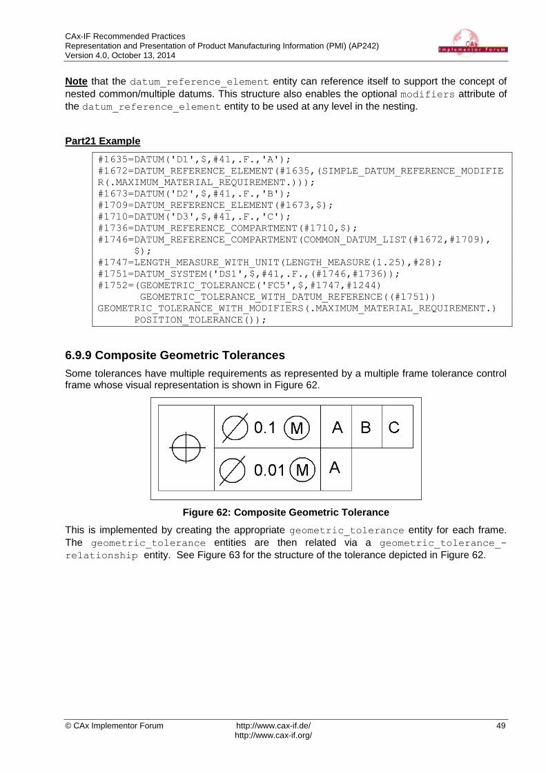
CAx-IF Recommended Practices Representation and Presentation of Product Manufacturing Information (PMI) (AP242) Version 4.0, October 13, 2014
© CAx Implementor Forum http://www.cax-if.de/ 49 http://www.cax-if.org/
Note that the datum_reference_element entity can reference itself to support the concept of
nested common/multiple datums. This structure also enables the optional modifiers attribute of
the datum_reference_element entity to be used at any level in the nesting.
Part21 Example
#1635=DATUM('D1',$,#41,.F.,'A');
#1672=DATUM_REFERENCE_ELEMENT(#1635,(SIMPLE_DATUM_REFERENCE_MODIFIE
R(.MAXIMUM_MATERIAL_REQUIREMENT.)));
#1673=DATUM('D2',$,#41,.F.,'B');
#1709=DATUM_REFERENCE_ELEMENT(#1673,$);
#1710=DATUM('D3',$,#41,.F.,'C');
#1736=DATUM_REFERENCE_COMPARTMENT(#1710,$);
#1746=DATUM_REFERENCE_COMPARTMENT(COMMON_DATUM_LIST(#1672,#1709),
$);
#1747=LENGTH_MEASURE_WITH_UNIT(LENGTH_MEASURE(1.25),#28);
#1751=DATUM_SYSTEM('DS1',$,#41,.F.,(#1746,#1736));
#1752=(GEOMETRIC_TOLERANCE('FC5',$,#1747,#1244)
GEOMETRIC_TOLERANCE_WITH_DATUM_REFERENCE((#1751))
GEOMETRIC_TOLERANCE_WITH_MODIFIERS(.MAXIMUM_MATERIAL_REQUIREMENT.)
POSITION_TOLERANCE());
6.9.9 Composite Geometric Tolerances
Some tolerances have multiple requirements as represented by a multiple frame tolerance control frame whose visual representation is shown in Figure 62.
Figure 62: Composite Geometric Tolerance
This is implemented by creating the appropriate geometric_tolerance entity for each frame.
The geometric_tolerance entities are then related via a geometric_tolerance_-
relationship entity. See Figure 63 for the structure of the tolerance depicted in Figure 62.
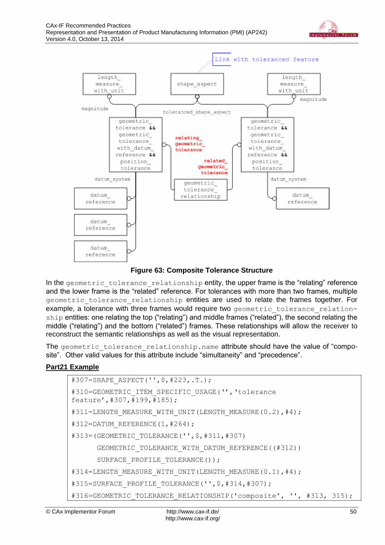
CAx-IF Recommended Practices Representation and Presentation of Product Manufacturing Information (PMI) (AP242) Version 4.0, October 13, 2014
© CAx Implementor Forum http://www.cax-if.de/ 50 http://www.cax-if.org/
Figure 63: Composite Tolerance Structure
In the geometric_tolerance_relationship entity, the upper frame is the “relating” reference
and the lower frame is the “related” reference. For tolerances with more than two frames, multiple
geometric_tolerance_relationship entities are used to relate the frames together. For
example, a tolerance with three frames would require two geometric_tolerance_relation-
ship entities: one relating the top (“relating”) and middle frames (“related”), the second relating the
middle (“relating”) and the bottom (“related”) frames. These relationships will allow the receiver to reconstruct the semantic relationships as well as the visual representation.
The geometric_tolerance_relationship.name attribute should have the value of “compo-
site”. Other valid values for this attribute include “simultaneity” and “precedence”.
Part21 Example
#307=SHAPE_ASPECT('',$,#223,.T.);
#310=GEOMETRIC_ITEM_SPECIFIC_USAGE(‘’,‘tolerance
feature’,#307,#199,#185);
#311=LENGTH_MEASURE_WITH_UNIT(LENGTH_MEASURE(0.2),#4);
#312=DATUM_REFERENCE(1,#264);
#313=(GEOMETRIC_TOLERANCE('',$,#311,#307)
GEOMETRIC_TOLERANCE_WITH_DATUM_REFERENCE((#312))
SURFACE_PROFILE_TOLERANCE());
#314=LENGTH_MEASURE_WITH_UNIT(LENGTH_MEASURE(0.1),#4);
#315=SURFACE_PROFILE_TOLERANCE('',$,#314,#307);
#316=GEOMETRIC_TOLERANCE_RELATIONSHIP('composite', '', #313, 315);
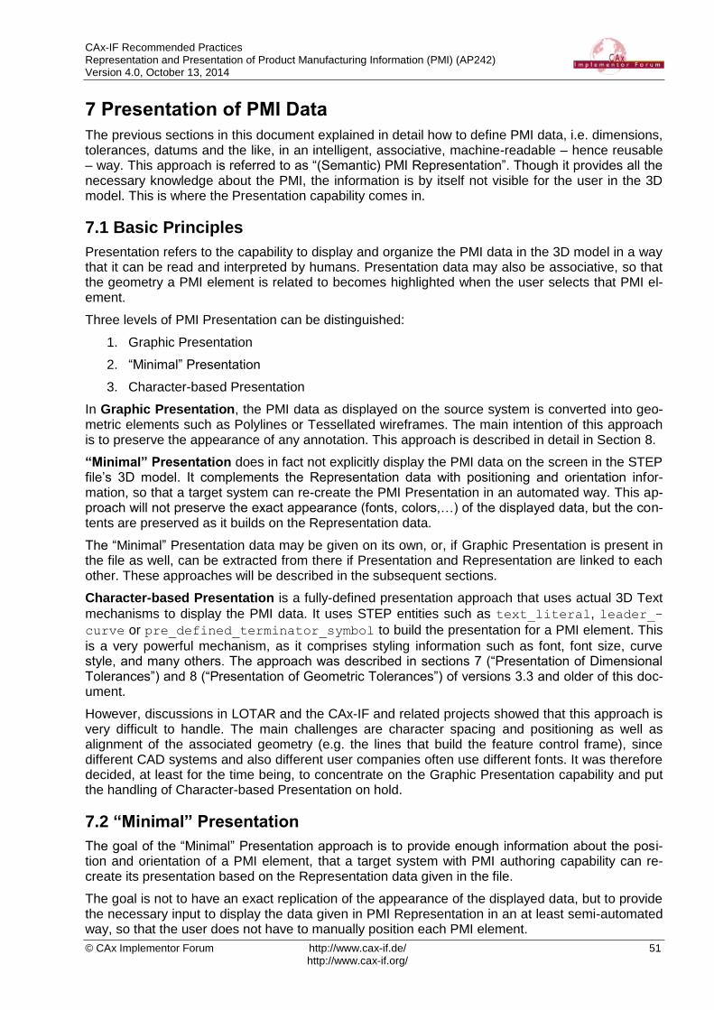
CAx-IF Recommended Practices Representation and Presentation of Product Manufacturing Information (PMI) (AP242) Version 4.0, October 13, 2014
© CAx Implementor Forum http://www.cax-if.de/ 51 http://www.cax-if.org/
7 Presentation of PMI Data
The previous sections in this document explained in detail how to define PMI data, i.e. dimensions, tolerances, datums and the like, in an intelligent, associative, machine-readable – hence reusable – way. This approach is referred to as “(Semantic) PMI Representation”. Though it provides all the necessary knowledge about the PMI, the information is by itself not visible for the user in the 3D model. This is where the Presentation capability comes in.
7.1 Basic Principles
Presentation refers to the capability to display and organize the PMI data in the 3D model in a way that it can be read and interpreted by humans. Presentation data may also be associative, so that the geometry a PMI element is related to becomes highlighted when the user selects that PMI el-ement.
Three levels of PMI Presentation can be distinguished:
1. Graphic Presentation
2. “Minimal” Presentation
3. Character-based Presentation
In Graphic Presentation, the PMI data as displayed on the source system is converted into geo-metric elements such as Polylines or Tessellated wireframes. The main intention of this approach is to preserve the appearance of any annotation. This approach is described in detail in Section 8.
“Minimal” Presentation does in fact not explicitly display the PMI data on the screen in the STEP file’s 3D model. It complements the Representation data with positioning and orientation infor-mation, so that a target system can re-create the PMI Presentation in an automated way. This ap-proach will not preserve the exact appearance (fonts, colors,…) of the displayed data, but the con-tents are preserved as it builds on the Representation data.
The “Minimal” Presentation data may be given on its own, or, if Graphic Presentation is present in the file as well, can be extracted from there if Presentation and Representation are linked to each other. These approaches will be described in the subsequent sections.
Character-based Presentation is a fully-defined presentation approach that uses actual 3D Text
mechanisms to display the PMI data. It uses STEP entities such as text_literal, leader_-
curve or pre_defined_terminator_symbol to build the presentation for a PMI element. This
is a very powerful mechanism, as it comprises styling information such as font, font size, curve style, and many others. The approach was described in sections 7 (“Presentation of Dimensional Tolerances”) and 8 (“Presentation of Geometric Tolerances”) of versions 3.3 and older of this doc-ument.
However, discussions in LOTAR and the CAx-IF and related projects showed that this approach is very difficult to handle. The main challenges are character spacing and positioning as well as alignment of the associated geometry (e.g. the lines that build the feature control frame), since different CAD systems and also different user companies often use different fonts. It was therefore decided, at least for the time being, to concentrate on the Graphic Presentation capability and put the handling of Character-based Presentation on hold.
7.2 “Minimal” Presentation
The goal of the “Minimal” Presentation approach is to provide enough information about the posi-tion and orientation of a PMI element, that a target system with PMI authoring capability can re-create its presentation based on the Representation data given in the file.
The goal is not to have an exact replication of the appearance of the displayed data, but to provide the necessary input to display the data given in PMI Representation in an at least semi-automated way, so that the user does not have to manually position each PMI element.

CAx-IF Recommended Practices Representation and Presentation of Product Manufacturing Information (PMI) (AP242) Version 4.0, October 13, 2014
© CAx Implementor Forum http://www.cax-if.de/ 52 http://www.cax-if.org/
The minimal presentation information can be given in two ways:
1. If Graphic Presentation is given in the file as well, and it is linked with the PMI Representa-tion (see section 7.3 below), the following data can be extracted from it:
User name of the PMI element
Orientation and Approximate location (annotation plane)
Attachment point(s) on the model geometry
Assignment of the presented PMI element to Saved Views
Styling information (color,…)
Equivalent Unicode String Validation Property
2. If no other presentation data is available at all, the minimal presentation can be given on its own, and comprises:
Orientation and Location of the PMI element
Attachment point(s) on the model geometry
A detailed description of the latter approach, including instantiation diagrams, will be given in a future version of this document, since the exact definition and use are currently under discussion.
7.3 Linking PMI Representation to Presentation
While the two basic approaches to transfer PMI data – Representation and Presentation – can exist in an unrelated, parallel way in a STEP file even though each of them is fully defined, there is a lot to be gained when the two are linked together.
STEP files which contain PMI Representation and Presentation in a linked way can be applied in downstream processes using the Representation, as well as for documentation purposes using the Presentation. But even more important, they allow for updating of individual Presentation elements when the model is modified at a later point in time.
In this case, the Representation provides the editable definition of the PMI, while the Presentation linked to it provides the data concerning position, styling and organization of the displayed ele-ment, so that a new Presentation element for the updated data can be created to replace the old one while preserving its behavior.
Links between Representation and Presentation often create n:m relationships, as several Repre-sentation elements may be presented in one Presentation element (e.g. a dimension with a datum attached), and vice versa there may be several Presentation elements for one Representation el-ement if it is displayed in different ways in different views for instance.
The core entity to create these links is draughting_model_item_association (DMIA), with
its attributes used in the following way:
DMIA.attribute Usage
name 'PMI representation to presentation link'
description (optional)
definition The PMI Representation element
used_representation The ‘global’ draughting_model (see section 9.2)
identified_item The PMI Presentation element (draughting_callout
or annotation_occurrence)
Table 13: Usage of DMIA to link Representation with Presentation

CAx-IF Recommended Practices Representation and Presentation of Product Manufacturing Information (PMI) (AP242) Version 4.0, October 13, 2014
© CAx Implementor Forum http://www.cax-if.de/ 53 http://www.cax-if.org/
On the Presentation side, the target entity will always be either a draughting_callout or an
annotation_occurrence. They serve as “anchor” for any presentation element, independent of
whether it is a graphic presentation or a full semantic presentation (3D Text).
On the Representation side, the following entity types (and complex instances of) can be refer-enced by the definition attribute:
dimensional_location (shape_aspect_relationship)
o dimensional_location_with_path
o angular_location
dimensional_size
o dimensional_size_with_path
o angular_size
geometric_tolerance
o geometric_tolerance_with_defined_unit
geometric_tolerance_with_defined_area_unit
o geometric_tolerance_with_modifiers
geometric_tolerance_with_maximum_tolerance
o modified_geometric_tolerance
o unequally_disposed_geometric_tolerance
o cylindricity_tolerance
o flatness_tolerance
o line_profile_tolerance
o position_tolerance
o roundness_tolerance
o straightness_tolerance
o surface_profile_tolerance
o geometric_tolerance_with_datum_reference
angularity_tolerance
circular_runout_tolerance
coaxility_tolerance
concentricity_tolerance
parallelism_tolerance
perpendicularity_tolerance
symmetry_tolerance
total_runout_tolerance
datum_feature (shape_aspect)
placed_datum_target_feature (datum_target<=shape_aspect)

CAx-IF Recommended Practices Representation and Presentation of Product Manufacturing Information (PMI) (AP242) Version 4.0, October 13, 2014
© CAx Implementor Forum http://www.cax-if.de/ 54 http://www.cax-if.org/
The approach is very similar to the mechanism used to link a presentation element with its associ-
ated geometry, as defined in section 9.3 below. The intent of the draughting_model_item_-
association is defined by its definition attribute, i.e. whether it points a PMI Representation
element or a shape_aspect defining a portion of geometry.
Figure 64 below gives an illustration of how this link will look like between a dimension and its presentation. In the example, a dimension with a plus/minus tolerance is defined on the Represen-tation side, which is being displayed as one Polyline Presentation element. The two are linked to-gether.
As stated in the introduction, Representation to Presentation relationships may be n:m relation-ships. However, it shall be ensured that the link between any representation element and associ-
ated presentation element is created only once; i.e. the combination of DMIA.definition and
DMIA.identified_item is unique.
Figure 64: Linking PMI Representation to (Polyline) Presentation

CAx-IF Recommended Practices Representation and Presentation of Product Manufacturing Information (PMI) (AP242) Version 4.0, October 13, 2014
© CAx Implementor Forum http://www.cax-if.de/ 55 http://www.cax-if.org/
8 Graphic Presentation
This section deals with the presentation of PMI elements and annotations in graphical form. The two related capabilities available in AP242 are “Polyline Presentation” and “Tessellated Presenta-tion”. This means that the information to be displayed is broken down into geometric elements. The advantages of Graphic Presentation are that since it is rendered, it is presented in the STEP file exactly as it was in the CAD system. Since the instantiation is done using basic geometric entities, basically every viewer or CAD system which finds the link in the file structure can display it.
The “Polyline Presentation” approach was originally developed with AP203e2 and AP214e3. It is used with these APs even though there are some restrictions and differences in the implementa-tion approaches. This is described in a separate document, the “Recommended Practices for Pol-yline Presentation” [1]. The following sections in this document deal exclusively with the implemen-tation of Graphic Presentation based on AP242 (DIS and later).
The information to be presented can be converted to geometry in different ways, which have an impact on how they will become instantiated in the STEP file. The main characteristics to be con-sidered are:
Outline Characters: Elements are shown by their outline.
Filled Characters: Elements are shown as solid or filled.
Stroked Characters: Elements are defined by their centerline
Geometric Elements: These include leader and witness lines, bounding boxes of feature control frames, and arrows (which may be filled).
Figure 65: Outline Characters (upper left), Filled Characters (upper right), Stroked Characters and Geometric Elements (below)
Independent from this, Graphic Presentation elements can be styled and arranged in Saved Views (see section 9.3.2) to provide the relevant set of PMI data to the user in the format defined on ex-port. The definition of various validation properties (see section 10) help to ensure the correctness and completeness of the information displayed.
8.1 Polyline Presentation
A polyline is a line created by a series of short straight line segments. The entity polyline is de-
fined in Part 42.
Using this type of entity, each PMI feature and 3D annotation can be exported as a
geometric_curve_set of polylines, circles and trimmed_curves where the basis curve
is a circle (circular arcs). Polylines are defined by a list of cartesian_points. The use of
composite_curves is also allowed; see section 0 below for details.
Note that these shall be located in a plane parallel to the definition plane of the annotation_-
plane the PMI element is assigned to, as described in section 9.1 below. Each Polyline annota-
tion has to be in set of elements of an annotation_plane.

CAx-IF Recommended Practices Representation and Presentation of Product Manufacturing Information (PMI) (AP242) Version 4.0, October 13, 2014
© CAx Implementor Forum http://www.cax-if.de/ 56 http://www.cax-if.org/
8.1.1 Basic Polylines
The following figure illustrates the basic structure for a PMI element presented by Polylines. This can be used to handle stroked and outline characters, as well as geometric elements:
Figure 66: Basic Polyline Definition
Part21 Example
#576=DRAUGHTING_CALLOUT('Simple Datum.1',(#581));
#581=ANNOTATION_CURVE_OCCURRENCE('Simple Datum.1',(#580),#577);
#577=GEOMETRIC_CURVE_SET('datum',(#582,#592,#597,#600,#606));
#582=POLYLINE('Simple
Datum.1',(#583,#584,#585,#586,#587,#588,#589,#590, #591));
#592=POLYLINE('Simple Datum.1',(#593,#594,#595,#596));
#597=POLYLINE('Simple Datum.1',(#598,#599));
#600=POLYLINE('Simple Datum.1',(#601,#602,#603,#604,#605));
#606=POLYLINE('Simple Datum.1',(#607,#608,#609,#610));
Pre-Processor Recommendations
The starting point for every annotation shall be a draughting_callout. Though technically this
is not mandatory, it is highly recommended to create it so, that:
draughting_callout is the starting point for each annotation, regardless of the tech-
nical approach used to present this annotation (i.e., Polyline, Tessellated or Character-based Presentation). This way, all capabilities that relate to annotations (e.g. annotation validation properties, linking annotations to geometry / other annotations / PMI representa-tion) can be defined independently from the actual presentation approach.
draughting_callout is the collector for all constituents of an annotation, i.e. what is
one annotation in the CAD system shall be one draughting_callout in the STEP file,
even or especially when the annotation is split into several subsets for text and geometry or stroked and filled elements (see section 8.3).
draughting_callout.name is the “user name” of the annotation. In most cases, this
name is automatically assigned by the system; it is the name by which the annotation is known to the user e.g. in the model tree.
annotation_curve_occurrence.name repeats the “user name” of the annotation, in
order to maintain compatibility with implementations not using the draughting_callout.
geometric_curve_set.name indicates the presented type of PMI; see section 8.4 be-
low for details.

CAx-IF Recommended Practices Representation and Presentation of Product Manufacturing Information (PMI) (AP242) Version 4.0, October 13, 2014
© CAx Implementor Forum http://www.cax-if.de/ 57 http://www.cax-if.org/
Post-Processor Recommendations
In cases where a draughting_callout is not present, the annotation_curve_occurrence
is the starting point for the Polyline annotation. This is the case e.g. for all AP214e3 and AP203e2 implementations of Polyline Presentation (see [1] for details).
8.1.2 Filled Polylines
The next figure shows the definition of a set of filled polylines. Note that the geometric definition of
the boundaries is the same as above. The specific subtype of annotation_occurrence carries
the information that these characters are to be filled.
Figure 67: Filled Polyline Definition
Pre-Processor Recommendations
The curves referenced as boundaries of the annotation_fill_area need to fulfill the following
requirements:
Each boundary has to be a closed curve
No two of these closed curves may intersect
All boundaries have to be coplanar.
It is allowed to have several outer boundaries in one set, so an entire text string can be presented
with one annotation_fill_area. One “inner point” needs to be defined to indicate where the
filling shall start. Even though efficient algorithms are available to determine the filled and unfilled portions of the annotation, the following convention can help to simplify the process, if the STEP
processor is capable of manipulating the polylines this way:
outer boundaries (enclosing a filled area) shall be oriented in a positive sense, i.e. counter-clockwise (by giving the points defining the polyline in the appropriate order)
inner boundaries (enclosing an unfilled area) shall be oriented the opposite way, i.e. clock-wise.
Note that due to the various algorithms that exist to determine the inner and outer boundaries in a set of closed curves like this, geometrically it would be most efficient to have only one outer
boundary per annotation_fill_area. But that would inflate the STEP file structure and make
evaluation and specifically validation much more complicated, if not impossible. It is therefore strongly recommended to not split up annotations below the granularity corresponding to the “Equivalent Unicode String” (see section 10.3.2). For instance, all boundaries belonging to the
presentation of the real value “3.200” have to be in the same annotation_fill_area.
The use of Composite Curves
Especially for the support of Filled Polylines, it can be meaningful to group geometric elements together in order to describe more complex boundaries consisting of Polylines as well as trimmed curves (circular arcs). This allows to render complex characters in a more exact way, e.g. to con-struct the shape of a ‘D’ from a polyline and a half circle.

CAx-IF Recommended Practices Representation and Presentation of Product Manufacturing Information (PMI) (AP242) Version 4.0, October 13, 2014
© CAx Implementor Forum http://www.cax-if.de/ 58 http://www.cax-if.org/
Hence, each boundary can be described as a composite_curve. Each portion of the boundary
is declared as a composite_curve_segment, and the transition attribute helps to satisfy the
requirements for the boundaries of an annotation_fill_area as listed above.
Figure 68: Definition of boundaries using composite_curves
Concerning the attribute values of composite_curve and composite_curve_segment, the
following recommendations are given:
composite_curve.self_intersect strictly has to be FALSE for the boundaries of
Filled Polylines
composite_curve_segment.transition shall always be 'continuous' with one
exception: it may be 'discontinuous' for the last segment of a composite_curve to
indicate it is open, e.g. when using it for stroked font or geometric elements in an annota-tion.
composite_curve_segment.same_sense can be used to manipulate the boundary
orientation, hence indicating inner and outer boundaries as described above.
Post-Processor Recommendations
In case an importing STEP processor capable of handling only basic polylines (see 8.1.1) encoun-ters a file with filled polylines (as defined in 8.1.2), these can still be imported by re-interpreting them in the following way:
treat the annotation_fill_area_occurrence as if it were an annotation_curve_-
occurrence. The cartesian_point given as fill style target as well as any
fill_area_styles shall be ignored. curve_styles, however, can be processed as
usual.
treat the annotation_fill_area as if it were a geometric_curve_set.
8.2 Tessellated Presentation
Starting with AP242 DIS, the new data model for tessellated geometry is available, and provides an alternative approach for graphic presentation. The implementation structure itself is very similar to the Polyline approach described above, with the simplification that it is not necessary to distin-guish between filled and unfilled elements, as they can be mixed in one tessellated annotation. The general conception is that especially for filled characters, the use of tessellated elements is much more efficient than the original approach described in 8.1.2.
The general approach to using tessellated geometry in STEP AP242 is described in the Recom-mended Practices for 3D Tessellated Geometry, which are currently in development.

CAx-IF Recommended Practices Representation and Presentation of Product Manufacturing Information (PMI) (AP242) Version 4.0, October 13, 2014
© CAx Implementor Forum http://www.cax-if.de/ 59 http://www.cax-if.org/
Figure 69: Definition of a Tessellated Presentation
The following rules apply for the creation of a tessellated annotation:
The starting point for each tessellated annotation shall be a draughting_callout so
that it can be universally referenced by other capabilities
The draughting_callout.name and tessellated_annocation_occurrence.
name carry the “user name” of the annotation (same as for Polylines)
The tessellated_geometric_set.name indicates the presented PMI type; see section
8.4 below for details.
All filled elements of the annotation are collected by complex_triangulated_-surface_set.
All stroked and outline elements of the annotation are collected by tessellated_-curve_set.
All coordinates_lists contain 3D coordinates.
In order to make the implementation more efficient from a data size point of view, and based on the fact that within each annotation all geometric elements are coplanar, it is rec-
ommended to create a complex instance of tessellated_geometric_set with
repositioned_tessellated_item (see highlighted entity in Figure 69) so, that for all
coordinates in the referenced coordinates_lists, the third coordinate equals 0.
Part 21 Example:
#42 = DRAUGHTING_CALLOUT('pmi.2',(#43));
#43 = TESSELLATED_ANNOTATION_OCCURRENCE('pmi.2',(#62),#44);
#44 = (REPOSITIONED_TESSELLATED_ITEM(#46)
REPRESENTATION_ITEM('linear dimension')
TESSELLATED_GEOMETRIC_SET((#45))
TESSELLATED_ITEM());
#45 = TESSELLATED_CURVE_SET(#47,([…]));
#46 = AXIS2_PLACEMENT_3D('',#63,#64,#65);
#47 = COORDINATES_LIST('',[…]);
8.3 Graphic Annotation Subsets
There are quite a number of reasons why a presentation element that is a single annotation in the source system may get split into several annotations during export to STEP. For instance with Pol-ylines it is clear that stroked/outlined elements will be in a separate annotation from filled elements due to the different required entity types (see 8.1.1 and 8.1.2), or a processor may decide to dis-tinguish between textual and graphical elements of an annotation.

CAx-IF Recommended Practices Representation and Presentation of Product Manufacturing Information (PMI) (AP242) Version 4.0, October 13, 2014
© CAx Implementor Forum http://www.cax-if.de/ 60 http://www.cax-if.org/
Basically all kinds of graphic presentation can be combined into a single annotation; it is thinkable to have the filled characters of the text as tessellated elements, in combination with basic polylines for the leader lines and other geometric elements.
Pre-Processor Recommendations
In all cases, the collector for all subsets of an annotation is the draughting_callout. The fol-
lowing rules apply:
For each annotation, there shall be exactly one draughting_callout collecting all its
subsets
The values of the name attributes of draughting_callout and of each applicable in-
stance of annotation_occurrence subtype in its set of contents shall be identical.
This is once again to guarantee interoperability with implementations not relying on
draughting_callout.
The values of the name attributes of the subsequent geometric_curve_set,
annotation_fill_area and tessellated_geometric_set, indicating the presented
PMI type, have to be identical as well.
Figure 70: An annotation comprised of different graphic presentation elements
Important Note: While it is technically possible to create a STEP file that contains Polyline Presentation and Tessellated Presentation, even mixed in one annotation, it is recommended that in one STEP file, only one Graphic Presentation approach (Polylines or Tessellated) shall be used.
Post-Processor Recommendations
When importing an annotation comprised of several subsets, this shall be done so that in the tar-get system, the result for the user is again a single element in the model tree.
When importing older files (AP214e3, AP203e2) with Polyline presentation, in which
draughting_callout was not yet used to collect the subsets of an annotation, the grouping
was done using annotation_occurrence_relationships which linked the respective in-
stances of annotation_occurrence subtypes together. The rules concerning the identical nam-
ing for the annotation’s “user name” and “presented PMI type” as stated above already applied back then, and can be used as an additional indication for the grouped elements (see [1] for de-tails).

CAx-IF Recommended Practices Representation and Presentation of Product Manufacturing Information (PMI) (AP242) Version 4.0, October 13, 2014
© CAx Implementor Forum http://www.cax-if.de/ 61 http://www.cax-if.org/
8.4 Indicating the Presented PMI Type
It is recommended that the name of the geometric_curve_set (for Basic Polylines), the
annotation_fill_area (for Filled Polylines) or the tessellated_geometric_set (for Tes-
sellated Presentation) to be included in the STEP file is taken from the list given below. These are based on the ANSI/ISO standards NF EN ISO 1101. The intention is to provide the user with a harmonized list of names for display in the feature tree or as a property.
Note that the name of the geometric_curve_set / annotation_fill_area /
tessellated_geometric_set is not intended to transport any intelligent (semantic) PMI infor-
mation.
Tolerance Types Dimension Types Datum Types Other
angularity
circular runout
circularity
coaxiality
concentricity
cylindricity
flatness
parallelism
perpendicularity
position
profile of line
profile of surface
roundness
straightness
symmetry
total runout
general tolerance
linear dimension
radial dimension
diameter dimension
angular dimension
ordinate dimension
curve dimension
general dimension
datum
datum target
note
label
surface roughness
weld symbol
Table 14: Suggested list of names
8.5 Styling the Annotation
Each annotation transformed into graphic presentation form must preserve its graphic characteris-tics (color, line type and width) and optional attributes (type of annotation, layer). The graphical attribute can be global for the annotation.
The style for the presentation will be defined at the applicable annotation_occurrence sub-
type, which in turn is a subtype of styled_item. The styles defined at this level shall be applied
to all entities in the annotation.

CAx-IF Recommended Practices Representation and Presentation of Product Manufacturing Information (PMI) (AP242) Version 4.0, October 13, 2014
© CAx Implementor Forum http://www.cax-if.de/ 62 http://www.cax-if.org/
Figure 71: Styling a Graphic Annotation for outline/stroked (top) an filled (bottom) Elements
Basically, all definitions given for the styling of surfaces and curves given in the “Recommended Practices for Model Styling and Organization” apply to graphic presentation as well. This also means that each annotation shall have at least one style assigned, either directly as described
here or indirectly via a draughting_model it is contained in (see section 9 below).
Note that in the case of Filled Polylines, a fill_area_style as well as a curve_style may be
defined. In order to guarantee interoperability with systems not supporting filled characters, the
curve_style shall always be given if the presentation is styled.
If certain elements within a graphically presented annotation shall have a different style (e.g. the text shall have a different color than the frame), this will be applied through a complex entity com-
posed of over_riding_styled_item and the applicable annotation_occurrence subtype.
Figure 72: Definition of the overriding style for a Polyline annotation
Figure 72 illustrates this for a Basic Polyline. The concepts described in the “Recommended Prac-tices for Model Styling and Organization” for overriding styles apply here as well. Since the portion of the presentation to be re-styled will in general consist of many constituents, an additional geo-metric set is needed to collect these. This shall reference the relevant subset of the geometric el-

CAx-IF Recommended Practices Representation and Presentation of Product Manufacturing Information (PMI) (AP242) Version 4.0, October 13, 2014
© CAx Implementor Forum http://www.cax-if.de/ 63 http://www.cax-if.org/
ements that are contained within the full set of presentation data for this PMI element, and have the name “over riding style set” so that it is clear that it is no PMI element by itself (compare sec-tion 8.4).
9 Presentation Organization
Regardless of the presentation approach used (Polyline / Tessellated / Semantic), the presented data can be organized in various ways. The main approaches for this are the use of annotation planes, saved views, and the capability to link annotations with the associated geometry they pro-vide information about.
9.1 Annotation Planes
In order to position PMI data and 3D annotations on the screen, users usually work with annotation planes. Each graphic annotation has to be assigned to a reference plane and positioned parallel to that, at a specific position related to the geometry. In some systems, the assignment of an annota-tion to an annotation plane also has an organizational aspect in addition to positioning the annota-tion in 3D space.
This position must be preserved after conversion of PMI and 3D annotations. In the case of Pol-
yline Presentation, the three-dimensional cartesian_points defining the polylines shall be
located in a plane that is parallel to the definition plane of the annotation_plane. The same
applies to the entries in the coordinates_lists of a Tessellated Presentation element.
Note that the orientation of the annotation_plane should be chosen so that it also indicates the
reading direction of the annotations assigned to that plane, i.e. the underlying axis placement shall be defined so, that
The x axis is the “line that is being written on”, indicating the reading direction
The y axis points upward from the base to the top of the characters
The z axis points towards the reader
The same applies for the measuring direction of dimensions given as Graphic Presentation – this
should also be taken from the orientation of the annotation_plane, if not from the order of re-
lated geometric elements.
Note that the definition plane of the annotation_plane can be given in two different ways: as
an (infinite) plane, defined by an axis placement, or as a planar_box, defined by an axis
placement, a size in x and a size in y (relative to the axis placement). Each pre-processor may choose which definition fits its internal data structure best; both definitions shall be supported on import.
Figure 73: Definition of the view plane

CAx-IF Recommended Practices Representation and Presentation of Product Manufacturing Information (PMI) (AP242) Version 4.0, October 13, 2014
© CAx Implementor Forum http://www.cax-if.de/ 64 http://www.cax-if.org/
Part21 Example
#571=PLANE('Front View.1',#570);
#572=ANNOTATION_PLANE('Front View.1',(#573),#571,(#580,#613));
#573=PRESENTATION_STYLE_ASSIGNMENT((NULL_STYLE(.NULL.)));
#580=DRAUGHTING_CALLOUT('Simple Datim.1',(#581));
#581=ANNOTATION_CURVE_OCCURRENCE('Simple Datum.1',(#582),#577);
#613=DRAUGHTING_CALLOUT('Circularity.1',(#614));
#614=ANNOTATION_CURVE_OCCURRENCE('Circularity.1',(#615),#611);
Note that due to the way annotations are created and handled in many CAD systems, the ele-
ments describing an annotation have to be in a plane parallel to the plane defining the anno-
tation_plane, and not necessarily exactly on that plane.
9.2 Global Draughting Model
In order to correctly include all the annotations in the STEP file structure so that they can be easily
found and organized later on, they will be collected in one draughting_model. Since this
draughting_model relates to all annotations in the file, it is called the “global” draughting_-
model.
It references all annotation_planes in the file, which, in turn, include all draughting_-
callouts in their sets of elements:
Figure 74: Linking the Annotations together
This global draughting_model also contains references to all geometry that shall be displayed
when viewing the model. Details about the application and interpretation of styles are described in the “Recommended Practices for Model Styling and Organization”, section 4.1 (“Global Styling Container”), and also in this document, section 9.3.2 (“Saved Views”).
9.3 Linking Annotations with other Elements
Though annotations by themselves already provide a lot of valuable information to the consumer of a model, their usefulness can be vastly enhanced by putting them in context, i.e. linking them with other elements in the file.

CAx-IF Recommended Practices Representation and Presentation of Product Manufacturing Information (PMI) (AP242) Version 4.0, October 13, 2014
© CAx Implementor Forum http://www.cax-if.de/ 65 http://www.cax-if.org/
In particular, three “targets” are of interest:
1. Linking PMI Presentation with Representation (see section 7.3 above)
2. Linking Annotations with Geometry (“cross-highlighting”)
3. Linking Annotations to other Annotations (grouping)
9.3.1 Linking Annotations with Geometry (“Cross-Highlighting”)
3D annotations in general and PMI elements in particular are usually linked with geometry, i.e. a specific portion of the geometric shape. For the user, this is typically evident by the fact when a face or edge on the model is selected (highlighted), all associated annotations become highlighted as well, and vice versa. This capability is referred to as “cross-highlighting”.
In order to define the portion of the geometry the annotation relates to, at first the corresponding geometric element has to be identified. In the example in Figure 75 below, this is an
avanced_face linked through some chain of elements to the advanced_brep_shape_repre-
sentation defining the geometric shape. Next, a shape_aspect will be defined so that the
face can be referred to. The link between the shape_aspect and the advanced_face is created
via an entity of type geometric_item_specific_usage:
Figure 75: Identification of the relevant portion of Geometry

CAx-IF Recommended Practices Representation and Presentation of Product Manufacturing Information (PMI) (AP242) Version 4.0, October 13, 2014
© CAx Implementor Forum http://www.cax-if.de/ 66 http://www.cax-if.org/
Part21 Example
#15=PRODUCT_DEFINITION_SHAPE('','',#14);
#21=(GEOMETRIC_REPRESENTATION_CONTEXT(3)GLOBAL_UNCERTAINTY_ASSIGNED
_CONTEXT((#20))GLOBAL_UNIT_ASSIGNED_CONTEXT((#16,#17,#19))REPRESENT
ATION_CONTEXT('',''));
#24=ADVANCED_BREP_SHAPE_REPRESENTATION('NONE',(#26),#21);
#25=SHAPE_DEFINITION_REPRESENTATION(#15,#24);
#26=MANIFOLD_SOLID_BREP('PartBody',#35);
#35=CLOSED_SHELL('Closed Shell',(#75,#124,#136,#180,#211,#266,
#290,#350,#410,#432,#439,#461,#468,#492,#509,#526,#543));
#350=ADVANCED_FACE('PartBody',(#313,#331,#349),#295,.T.);
#1180=SHAPE_ASPECT('','GDT',#15,.F.);
#1181=GEOMETRIC_ITEM_SPECIFIC_USAGE('','GDT',#1180,#24,#350);
The next step is to link the draughting_callout for the annotation to the identified geometry.
This is done using a draughting_model_item_association, which references the “global”
draughting_model, the identified item and the shape_aspect that relates to the portion of the
geometry that the annotation relates to, as defined above.
Figure 76 below illustrates the complete structure to identify the relevant portion of geometry and link the annotation to it. The entire path for the link is highlighted:
Figure 76: Associating the Annotation with the Geometry

CAx-IF Recommended Practices Representation and Presentation of Product Manufacturing Information (PMI) (AP242) Version 4.0, October 13, 2014
© CAx Implementor Forum http://www.cax-if.de/ 67 http://www.cax-if.org/
Part21 Example
#566=DRAUGHTING_MODEL('',(#572,#887),#21);
#572=ANNOTATION_PLANE('Front View.1',(#573),#571,(#580,#613));
#580=DRAUGHTING_CALLOUT('Simple Datum.1',(#581));
#581=ANNOTATION_CURVE_OCCURRENCE('Simple Datum.1',(#582),#577);
#1180=SHAPE_ASPECT('','GDT',#15,.F.);
#1182=DRAUGHTING_MODEL_ITEM_ASSOCIATION('','',#1180,#566,#580);
9.3.2 Linking Annotations to other Annotations
There are scenarios where it is useful to put annotations in a relationship with each other. For in-stance, for the “cross-highlighting” capability described above it shall be possible to link an annota-tion presenting a datum reference to the annotation presenting the datum.
Since, as mentioned several times before, draughting_callout is the “anchor” entity for any
annotation regardless of its implementation approach, this linking is done using draughting_-
callout_relationship.
Figure 77: Linking Annotations to other Annotations
Note that the link established by draughting_callout_relationship carries no other (se-
mantic) meaning besides the fact that the two annotations are related to each other. So with cross-highlighting, when one of the two annotations is being selected, the other shall be highlighted as well.
The relationship shall have no further effect, e.g. on the visibility of the linked annotations in views.
9.3.3 Grouping Annotations with Annotation Planes
As described in section 9.1 above, each graphic presentation annotation is bound to one annota-
tion_plane. The primary objective of this relationship is to provide information about location
and orientation of the annotation. Some CAx also interpret annotation entities which are defined on
the same annotation_plane as a means of grouping the data.
As a result, the convention is that, if an annotation_plane is contained in the set of items of a
draughting_model, all elements contained in the set of elements of the annotation_plane
are also contained (visible) in the draughting_model.
The use of annotation_plane to group draughting_callouts is shown in Figure 78 below.
This is appropriate for full model definition (see 9.2) or saved view definition (see 9.4.2)

CAx-IF Recommended Practices Representation and Presentation of Product Manufacturing Information (PMI) (AP242) Version 4.0, October 13, 2014
© CAx Implementor Forum http://www.cax-if.de/ 68 http://www.cax-if.org/
Figure 78: The use of annotation_planes to group some of the draughting_callouts.
9.4 Saved Views
9.4.1 Definition of Terms
A “saved view” in the context of PMI presentation in STEP as described in this document complies with the following definition taken from ISO 16792, section 5.6:
Saved Views
Saved views of a design model may be defined to facilitate presentation of the model and its an-notation. A saved view shall have an identifier, be retrievable on demand, contain a model coordi-nate system that denotes the direction of the view relative to the model and may contain one or more of the annotation plane(s), a selected set of annotation, or a selected set of geometry.
The following list of equivalent terms might help in technical discussions:
ISO 16792, ASME Y14.41-2003 - saved view
CATIA V5/V6 - capture
NX - work view
Creo (Pro/Engineer) - combined state
Note: The terms are not 100% equivalent with the Saved View definition. Not all of the capabilities listed above require the definition of a viewing orientation, which is necessary for the full definition of a Saved View. The terms are given here for a better general understanding. Annex E provides more details on how the corresponding CAD system mechanisms are translated to a Saved View in STEP.
9.4.2 Basic Saved View definition in STEP
From the model structure point of view, the definition of a Saved View can be broken down into two major characteristics:
what is being displayed (geometry and annotations)
from where it is being seen (model orientation)

CAx-IF Recommended Practices Representation and Presentation of Product Manufacturing Information (PMI) (AP242) Version 4.0, October 13, 2014
© CAx Implementor Forum http://www.cax-if.de/ 69 http://www.cax-if.org/
For each of these, there is a key entity in STEP, starting at which the corresponding information can be retrieved:
the draughting_model will define what is being displayed
the camera_model will define from where it is being seen
Note that only the combination of a draughting_model with a camera_model fulfills all criteria
of a Saved View. The camera_model.name will carry the name of the Saved View.
A draughting_model can also exist as a group of displayed annotations and geometry without
an associated camera_model, which equals for instance the “capture” concept in CATIA V5. A
draughting_model may also have several camera_models associated to it, which will display
the same set of elements from different positions in 3D space.
The base entity to start the definition of a Saved View in STEP is the draughting_model. It will
define the contents to be displayed. There is a difference in the usage compared to that defined in the Recommended Practices for 3D Text (see http://cax-if.org/joint_testing_info.html#recpracs), in
that the allowable entities for draughting_model items did not include draughting_callout
in 1999 when those Recommended Practices were created. This meant that the
draughting_model had to collect the annotation_occurrences defined as the contents of
each of the draughting_callouts.
With the addition of draughting_callout entities allowed to be present in the draughting_-
model.items list, the draughting_model can collect each draughting_callout entity di-
rectly. Since each of these callouts provides the presentation data for a dimension, geometric tol-erance or other item of annotation, and do it independent of the implementation approach taken for the annotation, this offers a neater solution.
The draughting_models – the global draughting_model as well as those defining the scope
of visible geometry and annotations for a Saved View – will share the same geometric_repre-
sentation_context as the shape_representations defined for the part. See section 9.4.3
below for how these draughting_models are related to each other.
It is recommended that name attribute of the draughting_model should be used to convey an
identifier for the selected subset of elements. In its set of items, it will reference the geometric and
annotation elements to be displayed. To complete the Saved View definition, a camera_model
will be included in its set of items, which will define the viewing point and the viewing orientation, and carry the name of the Saved View.
The definition of Saved Views in general, however, is not mandatory in most CAD systems. There also may be annotations that are not included in any Saved View, but they still are correctly in-
cluded in the STEP file structure through the global draughting_model.
Definition of the geometry to be displayed
In a Saved View – or a selected subset of the model in general – all or some of the geometric con-tents will be displayed. There may be more than one geometric representation describing the part.
In the current CAx-IF scope, the most likely combination is to have an advanced_brep_-
shape_representation (ABSR) for the solid part shape plus a constructive_geometry_-
representation (CGR) for Supplemental Geometry elements such as reference planes or cen-
ter axes. There also may be wireframe or surface representations as well, and they all share the same context. Hence, it needs to be identified which of these representations shall be visible in the
draughting_model, which is done via a mapped_item and a representation_map (see
Figure 79) for each representation of interest. The axis2_placement_3ds referenced as
mapping_source and mapping_origin shall define a unit transformation.
This allows defining a Saved View which for instance only shows the part shape, but not the sup-
plemental geometry, by mapping only the ABSR and not the CGR into the draughting_model.

CAx-IF Recommended Practices Representation and Presentation of Product Manufacturing Information (PMI) (AP242) Version 4.0, October 13, 2014
© CAx Implementor Forum http://www.cax-if.de/ 70 http://www.cax-if.org/
Figure 79: Defining a Saved View with draughting_model and camera_model
As stated in Part 46, only styled items shall be displayed. Hence, in order to convey the infor-mation that the target system shall use either the styling defined for the part itself or use its own default styles if none are given in the STEP file, a NULL style shall be assigned to the
mapped_item. Note that as stated in 9.1, if the toolkit used in the STEP processor does not allow
the creation of a NULL style, a style with an empty color should be created instead. By using this style, it is also possible to style the entire part differently in this specific view.
Also see the “Recommended Practices for Model Styling and Organization” for more information about the usage and interpretation of styles.
Definition of the annotations to be displayed
The second main ingredient in the definition of a Saved View is which annotations – PMI as well as “plain” 3D Text – shall be displayed. This is done by including the desired annotation elements, i.e. the corresponding instances of:
draughting_callout (or subtypes)
annotation_plane
into the set of items of the draughting_model.

CAx-IF Recommended Practices Representation and Presentation of Product Manufacturing Information (PMI) (AP242) Version 4.0, October 13, 2014
© CAx Implementor Forum http://www.cax-if.de/ 71 http://www.cax-if.org/
Note that while the first will include individual annotations, including an annotation_plane will
by definition (see 9.3.3) include all annotations associated with that plane.
Note that some systems offer mechanisms to control the affiliation of items to a defined set using layer assignments and toggling the visibility of these layers rather than managing the individual elements. Though this document will not give a detailed description of this approach (at least for now), the following recommendations are given to ensure interoperability:
Each layer shall be represented by an instance of presentation_layer_assignment
with the respective name and the assigned annotations referenced in its set of items.
The context_dependent_invisibility that controls which of the layers will be dis-
played in the selected set will reference the draughting_model as its presentation con-
text.
The actually displayed set of annotations, which is the result of combining all layer assign-
ments and visibility definitions, shall be included in the set of items of the draughting_-
model in addition, as stated above.
This will allow all importing systems to directly access the information to be displayed, while at the same time preserving the layer definitions for those systems building on them.
Definition of the viewing orientation and zoom factor
As stated in its definition, a Saved View not only refers to a subset of the model geometry and the annotations to be displayed in the view, but also defines the view point and direction of view rela-
tive to the model. In the STEP file, this is done by adding a camera_model_d3 to the set of items
of the draughting_model, as shown in Figure 80 below.
Note that it is this combination of camera_model_d3 and draughting_model which defines a
Saved View in STEP. There may be more than one camera_model_d3 in the set of items of the
draughting_model, meaning that the same contents will be displayed from different directions.
Hence, the name of the saved view is stored in the camera model’s name attribute.
Figure 80: Camera definition for a Saved View

CAx-IF Recommended Practices Representation and Presentation of Product Manufacturing Information (PMI) (AP242) Version 4.0, October 13, 2014
© CAx Implementor Forum http://www.cax-if.de/ 72 http://www.cax-if.org/
Part21 Example
#276=PLANAR_BOX('#276',73.59058615,71.21669627,#275);
#277=CARTESIAN_POINT('#277',(0.0,0.0,0.0));
#278=VIEW_VOLUME(.PARALLEL.,#277,40.620193,40.620193,.T.,162.48078
,.T.,.T.,#276);
#282=AXIS2_PLACEMENT_3D('#282',#279,$,$);
#283=CAMERA_MODEL_D3('TOP',#282,#278);
#315=DRAUGHTING_MODEL('#315',(#307,#283,#295,#369,#371),#269);
Note that in the context of the revision of Part 46, changes have been made concerning the use of
camera_model_d3 and view_volume. This Recommended Practice already reflects the agreed
changes (see http://www.wikistep.org/bugzilla/show_bug.cgi?id=3293 for details).
Recommendations for practical use:
the projection_point shall be at the origin (0/0/0) of the view_reference_system
the view_reference_system’s z axis shall be the viewing direction
the view_window placement shall not be rotated
Have the location of the view_window’s placement so that it centers the view_window
on (0/0)
The view_window shall be mapped to match the CAD system’s window as far as possible
while preserving the aspect ratio (see illustration below)
view_volume.front_plane_clipping and .back_plane_clipping shall be set to
'false'
The view_volume.view_plane_distance then determines the view distance – hence
the zoom factor – of the model display.
Figure 81: Mapping of the STEP view_window to the CAD system window
The key convention is that view reference system (VRS) has its origin at the projection point (PP). When this is applied to Figures 11 and 12 in Part 46 Edition 2 (ISO 10303-46:2008) section 4.4.36, it becomes clear that the view plane distance (VPD) equals the distance between eye location and target.
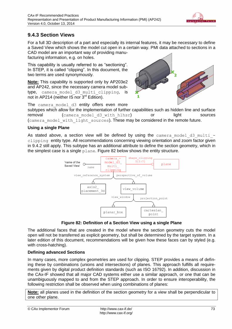
CAx-IF Recommended Practices Representation and Presentation of Product Manufacturing Information (PMI) (AP242) Version 4.0, October 13, 2014
© CAx Implementor Forum http://www.cax-if.de/ 73 http://www.cax-if.org/
9.4.3 Section Views
For a full 3D description of a part and especially its internal features, it may be necessary to define a Saved View which shows the model cut open in a certain way. PMI data attached to sections in a CAD model are an important way of providing manu-facturing information, e.g. on holes.
This capability is usually referred to as “sectioning”. In STEP, it is called “clipping”. In this document, the two terms are used synonymously.
Note: This capability is supported only by AP203e2 and AP242, since the necessary camera model sub-
type, camera_model_d3_multi_clipping, is
not in AP214 (neither IS nor 3rd Edition).
The camera_model_d3 entity offers even more
subtypes which allow for the implementation of further capabilities such as hidden line and surface
removal (camera_model_d3_with_hlhsr) or light sources
(camera_model_with_light_sources). These may be considered in the remote future.
Using a single Plane
As stated above, a section view will be defined by using the camera_model_d3_multi_-
clipping entity type. All recommendations concerning viewing orientation and zoom factor given
in 9.4.2 still apply. This subtype has an additional attribute to define the section geometry, which in
the simplest case is a single plane. Figure 82 below shows the entity structure.
Figure 82: Definition of a Section View using a single Plane
The additional faces that are created in the model where the section geometry cuts the model open will not be transferred as explicit geometry, but shall be determined by the target system. In a later edition of this document, recommendations will be given how these faces can by styled (e.g. with cross-hatching).
Defining advanced Sections
In many cases, more complex geometries are used for clipping. STEP provides a means of defin-ing these by combinations (unions and intersections) of planes. This approach fulfills all require-ments given by digital product definition standards (such as ISO 16792). In addition, discussion in the CAx-IF showed that all major CAD systems either use a similar approach, or one that can be unambiguously mapped to and from the STEP approach. In order to ensure interoperability, the following restriction shall be observed when using combinations of planes:
Note: all planes used in the definition of the section geometry for a view shall be perpendicular to one other plane.

CAx-IF Recommended Practices Representation and Presentation of Product Manufacturing Information (PMI) (AP242) Version 4.0, October 13, 2014
© CAx Implementor Forum http://www.cax-if.de/ 74 http://www.cax-if.org/
This ensures that the resulting section geometry could also be created by extruding a polyline. Some CAD systems even allow arbitrary cutting geometry (e.g. a sphere). This is out of scope.
Figure 83: Schematic representation of possible clipping cases
Each plane defines two half spaces (positive and negative), where the positive side is the one the normal is pointing to, as illustrated in Figure 83 above. When the section is applied, the contents of the negative half spaces will be removed, while the contents of the positive half spaces remain visible. There are two operations which allow combining two or more planes:
Union: any geometry contained in the positive half space of any of the referenced planes is displayed (see Figure 83b)
Intersection: only geometry contained in the positive half space of all referenced planes combined is displayed (see Figure 83c).
These operations can be combined to build more complex cases. The most famous example for this is the so-called “step”, see Figure 83d. It should be noted that using a mixture of several planes, especially when using intersections, may easily lead to an empty view (no part geometry remains in the resulting “positive” space), so this should be applied carefully.
The STEP entities for these operations are camera_model_d3_multi_clipping_union and
camera_model_d3_multi_clipping_intersection respectively, which can be included in
the shape_clipping set of camera_model_d3_multi_clipping. Figure 84 below illustrates
how to implement the “step” example from Figure 83d.
Note the different cardinality of the shape_clipping attribute in camera_model_d3_multi_-
clipping and its union / intersection relatives. It is of course also possible to define e.g. a union
of more than two planes at once, or to use several planes directly in the camera_model_d3_-
multi_clipping.

CAx-IF Recommended Practices Representation and Presentation of Product Manufacturing Information (PMI) (AP242) Version 4.0, October 13, 2014
© CAx Implementor Forum http://www.cax-if.de/ 75 http://www.cax-if.org/
Figure 84: Definition of a Saved View using a Combination of Planes
9.4.4 Relating the draughting_models
As stated before, the named draughting_model defines a subset of the geometry and annota-
tions defined in the file. If such a draughting_model references an annotation_plane, all the
draughting_callouts in its set of elements are added to the set. Where reference is required
for a subset of those annotations linked to an annotation_plane, the draughting_model
references those specific draughting_callouts directly.
The global draughting_model (see 9.2) and those defining sets of displayed elements are also
put in relation to each other.
Note that annotations may be contained in several Saved Views and hence will be referenced mul-
tiple times: once by the global draughting_model, and once for each set of items for display
they are contained in. In the receiving system, these annotations still shall be displayed only once.
Each draughting_model for a selected set of items has to be related to the global
draughting_model through a mechanical_design_and_draughting_relationship
(MDADR; a subtype of representation_relationship), where the global view is always refer-
enced in the rep_2 attribute, and the saved view in rep_1 (see Figure 85 below).
Note in earlier versions (before 4.0) of this document, the use of the attributes MDADR.rep_1 and
rep_2 was reversed compared to the description given above. However, MDADR is also a subtype
of definitional_representation_relationship, for with Part 43 states: “The represen-
tation indicated by rep_1 is part of the definition indicated by rep_2”. Since there are more
ways of differentiating the roles of the related draughting_models (see Table 15 below), it was
decided to fix this definition and reverse the attributes with version 4.0 of this document.
Note that the entity type mechanical_design_and_draughting_relationship is not in-
cluded in AP214 Edition 3. Hence, the use of the supertype representation_relationship is
recommended for this purpose in AP214 files, and has to be supported on import into AP242.

CAx-IF Recommended Practices Representation and Presentation of Product Manufacturing Information (PMI) (AP242) Version 4.0, October 13, 2014
© CAx Implementor Forum http://www.cax-if.de/ 76 http://www.cax-if.org/
Figure 85: Relating the global and Saved Views
The following table illustrates the differences between the global draughting_model and that for
a saved view:
Property Global Saved View
draughting_model.name '' (empty string) Name for the set of elements display in the view
related annotations all annotation_planes Some annotation_planes
and additional annotation ele-ments as per the Saved View definition
camera_model_d3 none related one or several in the set of items(*)
camera_model_d3.name Name of the Saved View as defined in the CAD system
MDADR attribute rep_2(**) rep_1
(**)
draughting_model_item_-
association
one for each annotation element
None
(*) = Though it is not mandatory to have a camera_model_d3 in the draughting_model’s set of items,
it is required to complete the Saved View definition. More than one camera_model_d3 means that there
are several Saved Views which display the same set of elements.
(**) = These two attributes were reversed in earlier versions (before 4.0) of this document.
Table 15: Global and Saved View draughting_model properties

CAx-IF Recommended Practices Representation and Presentation of Product Manufacturing Information (PMI) (AP242) Version 4.0, October 13, 2014
© CAx Implementor Forum http://www.cax-if.de/ 77 http://www.cax-if.org/
9.4.5 Advanced Saved View Implementation
While the basic view definition as given in 9.4.2 provides all the means necessary to define a Saved View as defined by the applicable standards, it has some limitations when compared to CAD system functionalities in this area. The most notable ones are the restriction to display one view at a time and the lack of “flat to screen” notes.
The advanced approach for the implementation of Saved Views builds on the basic approach de-fined in 9.4.2, but defines the additional data structures necessary to close the gaps mentioned above.
Figure 86 below gives an overview on the complete STEP files structure to define an Saved View in the advanced way. The blue elements in the bottom right hand corner give the basic definition, including the definition of which elements (geometry and annotations) will be displayed. The red elements above that define the additional structure for the advanced implementation.
Recommendations for practical use
There should be exactly one presentation_area in the presentation_set. Though it
is possible to create manifold views showing several individual views at once, the CAx-IF agreed that for the time being, only one view should be displayed at a time. Hence, the
same scaling recommendations as given in 9.4.2 apply to the camera_image and the presentation_size.
Instead of the mapped_item and representation_map used to link the presenta-
tion_area to the presentation_view, a representation_relationshop can also
be used, where the presentation_area is the rep_1 attribute, and presentation_-
view is rep_2.
Flat to Screen Notes
All the annotations and callouts that are items of a draughting_model rotate by default together
with the 3D model, because they share the same geometric_representation_context. But
there may be annotations that should always be visible in the 2D foreground plane, in the front of 3D object. This can be achieved by placing the respective annotations in the set of items of the
presentation_view in an advanced Saved View.
Flag notes
Building on this approach, the implementation scope can be extended to support Flag Notes in the future. These consist of two parts, a 3D note (the “flag”) which usually shows a number attached to the 3D part shape, and then the description text for this number, which will typically be displayed as a “flat to screen” note. Though the two components can already be implemented independently with the definitions given above, it still needs to be agreed how the two components can be asso-ciated with each other intelligently. The approach described in section 9.3.2 for linking annotations to other annotations can be a starting point for the discussion, should the requirement for flag notes become more substantial in the future.

CAx-IF Recommended Practices Representation and Presentation of Product Manufacturing Information (PMI) (AP242) Version 4.0, October 13, 2014
© CAx Implementor Forum http://www.cax-if.de/ 78 http://www.cax-if.org/
Figure 86: Advanced Saved View Implementation

CAx-IF Recommended Practices Representation and Presentation of Product Manufacturing Information (PMI) (AP242) Version 4.0, October 13, 2014
© CAx Implementor Forum http://www.cax-if.de/ 79 http://www.cax-if.org/
10 PMI Presentation Validation Properties
This section concerns the definition of ‘validation properties’ for PMI data. Similar to the Geometric Validation Properties, they aim to add information about the PMI data contained in the model to the STEP file, so that an importing systems has reference points to verify if all data has been pro-cessed correctly.
The exporting system will calculate the respective values based on the native model and write them as numerical or string values into the STEP file. The receiving system upon import will re-create the information from the file, and derive the same attributes based on the results. These will be compared the data given in the file, and if the values match, the import will be deemed success-ful. The approach used for implementation is based on the “general property” approach defined in Part 41, and widely used of other types of validation properties.
Note that at the moment, the PMI validation properties for the most part focus on Polyline Presen-tation. Following the implementation progress, further validation properties may be added here in later revisions of this document.
10.1 Validation Properties on the Part/Product level
In order to provide the user with a summary of PMI information in the file, validation properties can be defined at the top-level part (product) in the file.
10.1.1 Total number of annotations per file
The value contains the total number of annotations in the file, regardless of their semantic origin (PMI or other) and which views they are assigned to. The suggested strings to use in the name attributes are shown in Figure 87 below:
Figure 87: PMI Validation Property for total number of annotations in the file

CAx-IF Recommended Practices Representation and Presentation of Product Manufacturing Information (PMI) (AP242) Version 4.0, October 13, 2014
© CAx Implementor Forum http://www.cax-if.de/ 80 http://www.cax-if.org/
10.1.2 Total number of views
The total number of views in the file is also linked to the top-level product in the file. The STEP file structure is the same as for the total number of annotations, see Figure 87. The only difference is the suggested strings for the name attributes, which are:
Attribute Recommended value
property_definition.name 'pmi validation property'
representation.name ''
integer_representation_item.name 'number of views'
integer_representation_item.the_value (number of views)
Table 16: Attribute values for the 'number of view' validation property
10.2 Validation Properties for Saved Views
The entity that defines which elements are displayed in a Saved View is the draughting_model,
see section 9.4.2 for details. Hence, validation properties on a ‘per view’ basis shall be linked to
this entity. In order to define a property on a representation (here, the draughting_model), the
following construct is used:
Create a complex instance of draughting_model with characterized_object, using the
entity type characterized_representation. Properties can be attached to this complex in-
stance in the usual way. The characterized_object’s name and description shall not be in-
stantiated.
Figure 88: PMI Validation Property for Number of Annotations in a Saved View
Part21 Example
#100=(CHARACTERIZED_OBJECT(*,*) CHARACTERIZED_REPRESENTATION()
DRAUGHTING_MODEL() REPRESENTATION('PMI_TOP',(#150,#160,#170,#180),
#80));
#110=PROPERTY_DEFINITION('pmi validation property','',#100);
#120=PROPERTY_DEFINITION_REPRESENTATION(#110,#130);
#130=REPRESENTATION('',(#140),#80);
#140=INTEGER_REPRESENTATION_ITEM('number of annotations',4);

CAx-IF Recommended Practices Representation and Presentation of Product Manufacturing Information (PMI) (AP242) Version 4.0, October 13, 2014
© CAx Implementor Forum http://www.cax-if.de/ 81 http://www.cax-if.org/
Note that characterized_representation is not in AP203 or AP214. Even though it violates
a rule in EXPRESS (characterized_object and draughting_model have no common type
in their inheritance tree, and thus are not allowed to be combined into a complex instance), it was agreed to use the approach with the complex entity nevertheless. This means that in #100 of the
Part21 Example above, the entry characterized_representation is missing. This has to be
supported for backwards compatibility. See [1], section 6.2, for details.
10.3 Validation Properties for Graphic Annotations
Because of their very nature, validation of Graphic Annotations information content is limited, since once they have been rendered, all information about their contents is lost. The validation proper-ties provided for Graphic Presentation are therefore primarily of geometric nature. Content valida-tion information can be supplied by using specific Unicode strings.
The anchor entity for a Graphic Annotation is the draughting_callout. Hence, all validation
properties as far as they apply to the entire annotation, shall be attached at this level. Especially in the case when an annotation consists of several subsets, it is also possible to attach validation
properties at the sub-set level, i.e. the applicable subtype of annotation_occurrence. If e.g. a
Polyline annotation is divided into two subsets, the “curve length” validation property would store
the curve length for each subset at the corresponding annotation_curve_occurrence, while
at the draughting_callout it would store the total curve length for both subsets.
In order to define a validation property on a representation_item in the context of a specific
representation, the new intermediate entity characterized_item_within_representation
was introduced with AP242 and will be used as shown in Figure 89 below.
Note that this entity type is not present in AP203 and AP214. Previously, an approach using a
complex entity composed of annotation_occurrence and characterized_object was
proposed, similar to the one used above to define validation properties per view. This does, how-ever, violate the same rule in EXPRESS. See [1], section 6.3, for details.
10.3.1 Polyline Presentation Validation Properties
10.3.1.1 Polyline Curve Length
To make sure that no portions of the rendered annotation are lost, a validation property is defined which contains the total curve length, i.e. the sum of the length of all line segments and circular arcs making up the polyline annotation.
Part21 Example
#100=DRAUGHTING_MODEL('',(#150,#160,#170,#180), #80));
#150=ANNOTATION_PLANE('',(#151),#155,(#200,#220,#240));
#200=ANNOTATION_OCCURRENCE('linear dimension',(#201),#202);
#202=GEOMETRIC_CURVE_SET('linear
dimension',(#206,#207,#208,#209));
#205=CHARACTERIZED_ITEM_WITHIN_REPRESENTATION('','',#200,#100);
#210=PROPERTY_DEFINITION('pmi validation property','',#205);
#211=PROPERTY_DEFINITION_REPRESENTATION(#210,#212);
#212=REPRESENTATION('',(#213),#80);
#213=MEASURE_REPRESENTATION_ITEM('polyline curve length',
POSITIVE_LENGTH_MEASURE(25.4),#50);

CAx-IF Recommended Practices Representation and Presentation of Product Manufacturing Information (PMI) (AP242) Version 4.0, October 13, 2014
© CAx Implementor Forum http://www.cax-if.de/ 82 http://www.cax-if.org/
Figure 89: PMI Validation Property for Polyline Curve Length
10.3.1.2 Polyline Centroid
In order to verify the positioning of the Polyline annotation, a centroid shall be calculated for it, based on the following algorithm:
Each Polyline annotation consists of line segments and circular arcs.
The “centroid” of a line segment is the center point of the line.
The “centroid” of a circular arc is on the radius joining the center of the arc at the position
anglearc
anglearcradius
p_
2*)2
_sin(*
For a set of line segments and arcs, the “centroid” is arrived at by a composition of all the element centroids, with the length of each line segment or arc as weight (similar as for a set of solids or surfaces).
Note that since the lengths of the line segments and arcs are used as weights to compose the Polyline centroid, calculating the Polyline Curve Length and the Polyline Centroid validation prop-erty at the same time is very efficient.
The approach and file structure used will be similar to the one defined in Section 10.3.1 for the Polyline Curve Length, with the difference that the item contained in the representation will be a
cartesian_point, the name of which shall be ‘polyline centre point’:
Attribute Recommended value
property_definition.name 'pmi validation property'
representation.name ''
cartesian_point.name 'polyline centre point'
Table 17: Attribute values for the 'poyline centroid' PMI Validation Property

CAx-IF Recommended Practices Representation and Presentation of Product Manufacturing Information (PMI) (AP242) Version 4.0, October 13, 2014
© CAx Implementor Forum http://www.cax-if.de/ 83 http://www.cax-if.org/
10.3.2 Tessellated Presentation Validation Properties
The implementation structure for Tessellation Presentation validation properties equals those for
Polyline Presentation. Depending on whether the tessellated_geometric_set (see Figure 69
in section 8.2) contains curves or surfaces, different validation properties apply:
Tessellated curves: Number of Segments, Tessellated Curve Length, Centroid
Tessellated surfaces: Number of Facets, Tessellated Surface Area, Centroid
Of course a tessellated_geometric_set can contain both types of geometry, e.g. when a
feature control frame with filled font text is presented. In this case, all of the properties listed above apply, with a combined centroid.
More details on Tessellated Geometry and the corresponding validation properties are described in the Recommended Practices for 3D Tessellated Geometry.
Tessellated Presentation validation properties shall be attached to:
The draughting_callout, with values corresponding to the entire annotation
The tessellated_annotation_occurrence, in case annotation subsets are defined.
All validation properties in this section follow the pattern defined in Figure 89, which is therefore not repeated here.
Note that in all cases, the name of the property_definition is ‘pmi validation property’, and
not ‘tessellated validation property’, which gives a clear distinction between validation properties applicable to the part shape and those applicable to annotations.
10.3.2.1 Number of Segments
All tessellated geometry is comprised of a number of basic geometric objects. In the case of curves or wires, these are represented by a set of connected line segments. The number of seg-ments in every curve or wire is invariant, and can therefore be used as a validation property.
Attribute Recommended value
property_definition.name 'pmi validation property'
representation.name ''
integer_representation_item.name 'number of segments'
integer_representation_item.the_value (number of segments)
Table 18: Attribute values for the 'number of segments' PMI Validation Property
10.3.2.2 Tessellated Curve Length
The total length of all segments in a tessellated curve or curve set can be validated to make sure the information was not lost during transfer. It is easily calculated by summing up the lengths of the individual straight segments.
Attribute Recommended value
property_definition.name 'pmi validation property'
representation.name ''
measure_representation_item.name 'tessellated curve length'
measure_representation_item.
value_component (positive_length_measure(value))
Table 19: Attribute values for the 'tessellated curve length' PMI Validation Property

CAx-IF Recommended Practices Representation and Presentation of Product Manufacturing Information (PMI) (AP242) Version 4.0, October 13, 2014
© CAx Implementor Forum http://www.cax-if.de/ 84 http://www.cax-if.org/
10.3.2.3 Tessellated Curve / Surface Centroid
A centroid is the center of a geometric extent. In the case of Tessellated Presentation, this extent can be defined by a surface (where the centroid is the balance point), or line segment (where the centroid is the center point of the segment). For a set of line segments, the centroid is arrived at by a composition of all the element centroids, with the length of each line segment as weight (similar as for a set of surfaces).
Since combining the centroids of different classes of geometry (surfaces and curves) into one point can lead to mismatches upon evaluation, it was agreed to keep the centroids separate and actually define two points, one for the surface content and one for the curve content. Of course each point shall be defined only if the corresponding class of geometry is used in the respective annotation.
Note that since the lengths of the line segments and the areas of the surfaces are used as weights to compose the centroid, calculating the Tessellated Curve Length, Tessellated Surface Area and the Centroid validation property at the same time is very efficient.
Attribute Recommended value
property_definition.name 'pmi validation property'
representation.name ''
cartesian_point.name 'tessellated surface centre point'
cartesian_point.name 'tessellated curve centre point'
Table 20: Attribute values for the 'tessellated centroid' PMI Validation Property
10.3.2.4 Number of Facets
All tessellated geometry is comprised of a number of basic geometric objects; in the case of sur-faces, these facets are typically triangles. In contrast to exact geometry with topology, in tessellat-ed geometry the number of elements in a body is invariant, and can therefore be used as a valida-tion property.
Attribute Recommended value
property_definition.name 'pmi validation property'
representation.name ''
integer_representation_item.name 'number of facets'
integer_representation_item.the_value (number of facets)
Table 21: Attributes values for the 'number of facets' PMI Validation Property
10.3.2.5 Tessellated Surface Area
For tessellated geometry, calculation of this value is done by simply summing up the individual area values of all facets contained in the surface set of annotation the validation property is de-fined for.
Attribute Recommended value
property_definition.name 'pmi validation property'
representation.name ''
measure_representation_item.name 'tessellated surface area'
measure_representation_item.
value_component (area_measure(value))
Table 22: Attribute values for the 'tessellated surface area' PMI Validation Property
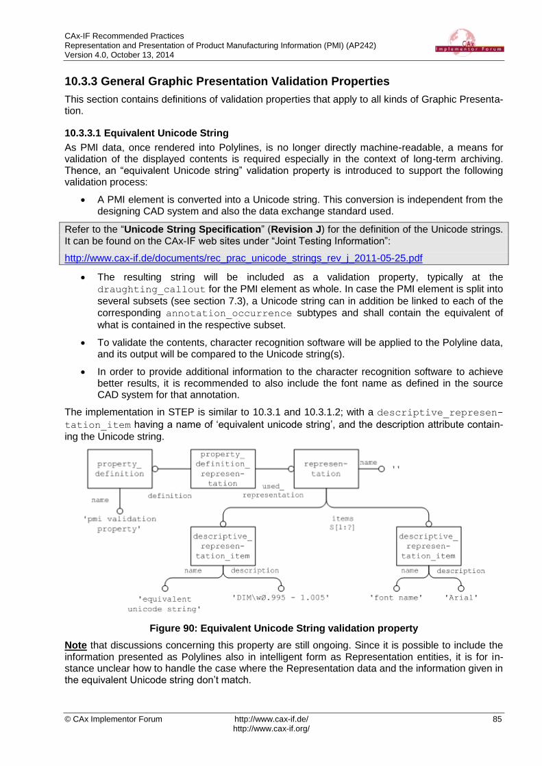
CAx-IF Recommended Practices Representation and Presentation of Product Manufacturing Information (PMI) (AP242) Version 4.0, October 13, 2014
© CAx Implementor Forum http://www.cax-if.de/ 85 http://www.cax-if.org/
10.3.3 General Graphic Presentation Validation Properties
This section contains definitions of validation properties that apply to all kinds of Graphic Presenta-tion.
10.3.3.1 Equivalent Unicode String
As PMI data, once rendered into Polylines, is no longer directly machine-readable, a means for validation of the displayed contents is required especially in the context of long-term archiving. Thence, an “equivalent Unicode string” validation property is introduced to support the following validation process:
A PMI element is converted into a Unicode string. This conversion is independent from the designing CAD system and also the data exchange standard used.
Refer to the “Unicode String Specification” (Revision J) for the definition of the Unicode strings. It can be found on the CAx-IF web sites under “Joint Testing Information”:
http://www.cax-if.de/documents/rec_prac_unicode_strings_rev_j_2011-05-25.pdf
The resulting string will be included as a validation property, typically at the
draughting_callout for the PMI element as whole. In case the PMI element is split into
several subsets (see section 7.3), a Unicode string can in addition be linked to each of the
corresponding annotation_occurrence subtypes and shall contain the equivalent of
what is contained in the respective subset.
To validate the contents, character recognition software will be applied to the Polyline data, and its output will be compared to the Unicode string(s).
In order to provide additional information to the character recognition software to achieve better results, it is recommended to also include the font name as defined in the source CAD system for that annotation.
The implementation in STEP is similar to 10.3.1 and 10.3.1.2; with a descriptive_represen-
tation_item having a name of ‘equivalent unicode string’, and the description attribute contain-
ing the Unicode string.
Figure 90: Equivalent Unicode String validation property
Note that discussions concerning this property are still ongoing. Since it is possible to include the information presented as Polylines also in intelligent form as Representation entities, it is for in-stance unclear how to handle the case where the Representation data and the information given in the equivalent Unicode string don’t match.

CAx-IF Recommended Practices Representation and Presentation of Product Manufacturing Information (PMI) (AP242) Version 4.0, October 13, 2014
© CAx Implementor Forum http://www.cax-if.de/ 86 http://www.cax-if.org/
10.3.3.2 Affected Geometry
In addition to validation that the contents are complete, it is also an important of the PMI definition to which elements in the model a PMI statement applies. Since there are a number of examples where the topologic definition of the geometry changes during the conversion via STEP (the most popular example being a cylinder becoming split into two half-cylinders), it is important to provide a means of validating that the geometry affected by a PMI statement altogether remains unchanged.
Depending on the type of the underlying PMI statement, the “affected geometry” validation proper-ty will transfer either:
the total surface area for PMI associated with faces (e.g. affected by a flatness tolerance)
the total curve length for PMI associated with curves (e.g. a dimension).
The STEP file structure to define this validation property is the same as given in 10.3.1.1 for the
Validation Property “Polyline Curve Length”, only that the name of the measure_represen-
tation_item shall be either 'affected area' or 'affected curve length'.
Notes: PMI Annotations can be attached to elements of Supplemental Geometry as well, for in-stance a reference plane (see corresponding Recommended Practices). The link between an an-notation and supplemental geometry works in the same way as between an annotation and part geometry described in section 9.3.1 above.
In some CAD systems, reference planes and axes are defined as unbounded (infinite) elements. In such a case, the “affected geometry” validation property shall not be applied since it would not render meaningful results.
There are two scenarios: the elements are unbounded in the exporting system; then, the validation property shall not be created in the STEP file; second, the exporting system has bounded ele-ments, hence creates the validation property in the file, but the importing system uses unbounded elements and discards the boundaries defined in the file, then it shall not evaluate the validation property.
Note that his validation property is also applicable to Semantic Presentation, but the correspond-ing STEP structure has not yet been defined.
10.3.4 Combining PMI Validation Properties for Efficient Implementation
Each of the PMI Validation Properties described above follows the exact same pattern for its defi-
nition: property_definiton property_definition_representation re-
presentation representatation_item. In a larger file, where there are many validation
properties – especially if there are many PMI annotations, each with its own set of properties – this can result in a significant number of entities, especially representations, which may have an impact on system performance.
Hence it was agreed that under specific circumstances, multiple validation properties can be com-
bined so they share the same property_definition, property_definition_re-
presentation and respresentation. The resulting structure is illustrated in Figure 91 below.
Validation properties can be combined in this way, if they are:
of the same type (property_definition.name)
attached to the same model element (property_definition.definition)
Note that the representation.name has to be empty. The individual validation properties can
be distinguished by their respective representation_item.name. Since each validation prop-
erty is instantiated at most once per model element, this does not introduce any ambiguities.

CAx-IF Recommended Practices Representation and Presentation of Product Manufacturing Information (PMI) (AP242) Version 4.0, October 13, 2014
© CAx Implementor Forum http://www.cax-if.de/ 87 http://www.cax-if.org/
Figure 91: Combining all Tessellated Presentation validation properties in one property def-inition
Part21 Example
#100=DRAUGHTING_MODEL('',(#150,#160,#170,#180),#80));
#150=ANNOTATION_PLANE('',(#151),#155,(#200,#220,#240));
#200=TESSELLATED_ANNOTATION_OCCURRENCE('linear
dimension',(#201),#202);
#205=CHARACTERIZED_ITEM_WITHIN_REPRESENTATION('','',#200,#100);
#210=PROPERTY_DEFINITION('pmi validation property','',#205);
#211=PROPERTY_DEFINITION_REPRESENTATION(#210,#212);
#212=REPRESENTATION('',(#213,#214,#215,#216,#217),#80);
#213=INTEGER_REPRESENTATION_ITEM('number of segments',42);
#214=MEASURE_REPRESENTATION_ITEM('tessellated curve length',
POSITIVE_LENGTH_MEASURE(25.4),#50);
#215=CARTESIAN_POINT('tessellated curve centre point',
(2.4185923,0.0582896,12.492895));
#216=INTEGER_REPRESENTATION_ITEM('number of facets',17);
#217=MEASURE_REPRESENTATION_ITEM('tessellated surface area',
AREA_MEASURE(47.168146),#51);

CAx-IF Recommended Practices Representation and Presentation of Product Manufacturing Information (PMI) (AP242) Version 4.0, October 13, 2014
© CAx Implementor Forum http://www.cax-if.de/ 88 http://www.cax-if.org/
10.4 PMI Validation Properties Attribute Summary
The following table summarizes the attribute values for all PMI Validation Properties as defined above:
Validation Property property_defi-
nition.name
property_definition
.definition
representation_item
.name and type
Total Number of Annotations per File
‘pmi validation property’
product_definition_-
shape ‘number of annotations’ integer_rep_item
Total Number of Views per File
‘pmi validation property’
product_definition_-
shape ‘number of views’ integer_rep_item
Number of Annota-tions per Saved View
‘pmi validation property’
draughting_model &&
characterized_repres. ‘number of annotations’ integer_rep_item
Polyline Curve Length
‘pmi validation property’
characterized_item_
within_rep
draughting_callout
‘polyline curve length’ positive_length_measure
Polyline Centroid ‘pmi validation property’
characterized_item_
within_rep
draughting_callout
‘polyline centre point’ cartesian_point
Tessellated Number of Segments
‘pmi validation property’
characterized_item_
within_rep
draughting_callout
‘number of segments’ integer_rep_item
Tessellated Curve Length
‘pmi validation property’
characterized_item_
within_rep
draughting_callout
‘tessellated curve length’ positive_length_measure
Tessellated Curve Centroid
‘pmi validation property’
characterized_item_
within_rep
draughting_callout
‘tessellated curve centre point’ cartesian_point
Tessellated Surface Centroid
‘pmi validation property’
characterized_item_
within_rep
draughting_callout
‘tessellated surface centre point’ cartesian_point
Tessellated Number of Facets
‘pmi validation property’
characterized_item_
within_rep
draughting_callout
‘number of facets’ integer_rep_item
Tessellated Surface Area
‘pmi validation property’
characterized_item_
within_rep
draughting_callout
‘tessellated surface area’ area_measure
Equivalent Unicode String
‘pmi validation property’
characterized_item_
within_rep
draughting_callout
‘equivalent unicode string’ descriptive_rep_item
Equivalent Unicode String – OCR Font
‘pmi validation property’
characterized_item_
within_rep
draughting_callout
‘font name’ descriptive_rep_item
Affected Geometry ‘pmi validation property’
characterized_item_
within_rep
draughting_callout
‘affected area’ area measure
or
‘affected curve length’
positive_length_measure
Table 23: Summary of PMI Validation Property Attributes

CAx-IF Recommended Practices Representation and Presentation of Product Manufacturing Information (PMI) (AP242) Version 4.0, October 13, 2014
© CAx Implementor Forum http://www.cax-if.de/ 89 http://www.cax-if.org/
Annex A Referenced Documents
The following documents are referenced throughout this document. They are available on the CAx-IF homepages at www.cax-if.de or www.cax-if.org under “Joint Testing Information / Recommend-ed Practices”:
[1] “Recommended Practices for PMI Polyline Presentation (AP203/AP214)” – Release 2.3; October 10, 2014.
[2] “PMI Unicode String Specification - Examples and Mapping Strategies” – Revision J; May 25, 2011
Additional information on the Representation and Presentation of PMI can also be found on the WikiSTEP pages, see www.wikistep.org.
Annex B Known Issues
Description Bugzilla # Status
Datum feature established from a thread features #4194 AP242 Edition 2
Size Spotface modifier #4215 More discussion
"Polar coordinate" tolerance zone #4219 AP242 Edition 2
Thread dimension and tolerance #4197 AP242 Edition 2
Geometric tolerance applied to thread feature (MD, LD, PD) #4220 AP242 Edition 2
ISO 1101-2012 not supported features #4774 AP242 Edition 2
Annex C Definitions of Terms for PMI in CAx-IF / LOTAR
The following section provides a harmonized definition of PMI-related terms as they are under-stood and used within the CAx-IF and LOTAR projects.
C.1 Product and Manufacturing Information (PMI)
Product and Manufacturing Information (PMI) is used in 3D Computer-aided Design (CAD) sys-tems to convey information about the definition of a product’s components for manufacturing, in-spections and sustainment, which supplements the geometric shape of the product. This includes – but is not limited to – data such as dimensions, tolerances, surface finish, weld symbols, material specifications, 3D annotations and user defined attributes. The term PMI, used by itself, relates to a certain information content within a product definition; i.e. it indicates what information is being stored, independent from how it is being stored.
Though PMI is generally accepted to be the generic designation, the term Geometric Dimensions and Tolerances (GD&T; sometimes also listed as Geometric Dimensioning and Tolerancing) is often used synonymously, as it is the main type of PMI that is currently in focus. Other synony-mously used terms are: General Tolerances and Annotations, Annotation, Smart Dimensions, Functional Tolerancing and Annotation (FT&A) or Geometric Product Specification (GPS). Some of these are specific to a particular CAD system. Industry standards for defining PMI include stand-ards such as ASME Y14.5, ASME Y14.41 and ISO 1101, ISO 16792 respectively.
C.1.1 Geometric Dimensions & Tolerances (GD&T)
Geometric Dimensions & Tolerances (GD&T) are a type of Product and Manufacturing Information (PMI) that can be either computed automatically by a CAD system, or entered manually by the user. The definitions below are additions to the terms mentioned in section 3.6 of EN/NAS9300-100:

CAx-IF Recommended Practices Representation and Presentation of Product Manufacturing Information (PMI) (AP242) Version 4.0, October 13, 2014
© CAx Implementor Forum http://www.cax-if.de/ 90 http://www.cax-if.org/
Explicit Tolerance: Any tolerance with a stated (numeric) value, regardless of how or where it is applied. Explicit tolerances can be applied through general notes, flag notes, PMI or tolerance dimensions. This must be attributable to a specific feature, feature set and/or da-tum reference (e.g. position, orientation). Standard +/- .03 notes may be explicit, depending on their use.
Implicit Tolerance: Any tolerance where there is no stated value and acceptability of the feature is defined by engineering to be through visual comparison to the appearance in the CAD model. Standard +/- .03 notes may also be implicit, depending on their use.
Explicit Dimension: The required nominal value is stated in the CAD model so that it can be obtained without interrogation.
Implicit Dimension: The nominal value can only be obtained by interrogation (i.e. feature to feature measuring) of the CAD model.
C.2 Semantic Representation
Semantic Representation designates a certain way how information is being stored; it does not relate to the information content itself. Semantic Representation captures the meaning (intent) and relationships (context) of a character, word, phrase, sentence, paragraph, specification, or symbol without using any of the visual characters or constructs that are needed for a human to understand it – such as the letters, graphical symbols, lines and arrows used on engineering drawings.
The main purpose of Semantic Representation is to facilitate automated consumption of the data, e.g. for later re-use or for downstream applications. It applies to various types of data, such as PMI, Composite Material Definition, and others.
Example – The Semantic Representation of a Linear Dimension includes all of the information needed to understand the specification (the type of dimension, between which features it is de-fined…), without any of the graphic components such as dimension lines and extension lines, their direction, arrowheads and the dimension value.
C.3 Presentation
Presentation designates a certain way how information is being stored; it does not relate to the information content itself. Presentation defines the visual representation of a character, word, phrase, sentence, paragraph, specification, or symbol in way that is understandable by humans. Presentation is a generic term that applies to any form of human-readable information transfer; this can for instance be a handwritten note, an engineering drawing, or the display of a 3D CAD model on a computer screen.
The main purpose of Presentation is to facilitate human comprehension of the data, e.g. to manu-facture, inspect, assemble or maintain the product described by the data. For a correct interpreta-tion of the presented data, it is required that the reader is familiar with the alphabet used and the general type of information being presented.
In the context of 3D CAD, the term Presentation relates to elements that are visible in the display of a 3D model and are either located (positioned) in 3D space, i.e. they rotate and move with the model, or in a fixed 2D plane. Elements of Presentation can typically by styled (e.g. colored), orga-nized (e.g. in specific views), and associated with other elements of the model. Presented types of data typically are geometry (3D shapes, surfaces, curves, points) and characters (letters, numbers, symbols).
C.3.1 Character-based Presentation
Character-based Presentation is a type of Presentation where the conveyed information is stored as characters (letters, numbers, and symbols). These characters are typically stored in a string variable that can be retrieved and edited in a consuming application. The appearance of Charac-
CAx-IF Recommended Practices Representation and Presentation of Product Manufacturing Information (PMI) (AP242) Version 4.0, October 13, 2014
© CAx Implementor Forum http://www.cax-if.de/ 91 http://www.cax-if.org/
ter-based Presentation depends on the font being used and may change if the originating system and the consuming application use different fonts. To ensure no characters are lost from creation to consumption, the alphabet (character encoding) used must be defined as well.
Example – In ASCII, the letter ‘A’ is stored as character code ‘0x41’ (hexadecimal).
Character-based Presentation is often supplemented by geometric elements, such as leader lines, curves or terminator symbols.
C.3.2 Graphic Presentation
Graphic Presentation is a type of Presentation where the conveyed information is converted to geometric elements (lines, arcs, surfaces) by the source system in a way that preserves the exact appearance (color, shape, positioning) of the presented information. The arrangement of these geometric elements can be interpreted by a competent human by looking at them, while the infor-mation content is no longer directly computer-accessible.
Example – A simple graphic presentation of the letter ‘A’ is given by three straight lines. A more complex graphic presentation could have ten straight lines and six circular arcs, but would still be recognizable as an ‘A’ to a human familiar with the Latin alphabet. In both cases, a computer can only access the geometric definition of the individual elements (start and end coordinates for each line), but not the fact that it is the letter ‘A’ that is being presented.
Graphic Presentation does not require defining the font or alphabet (character encoding) originally used in the creation of the presented data. In the way Graphic Presentation data is stored, there is typically no distinction between geometric elements that are visual representations of characters, and geometric elements that are visual representations of other constructs, such as leader lines, curves or terminator symbols.
Note – An indirect way of accessing the information content stored as Graphic Presentation is the application of character recognition software that will attempt to identify the original characters from the geometric elements that make up their visual representation. Character recognition, how-ever, has its limitations depending on the algorithms used, the fonts and alphabet involved, and the granularity of the Graphic Presentation geometry elements. Its results cannot be used with the same level of reliability as Character-based Presentation.
C.3.2.1 Polyline Presentation
Polyline Presentation designates a specific implementation form of Graphic Presentation that is supported by many STEP Application Protocols, including AP203e2 (ISO10303-203:2011), AP214e3 (ISO10303-214:2010) and AP242 (ISO10303-242:2014). It supports all the characteris-tics of Graphic Presentation. A Polyline is defined as an ordered list of 3D points, which are con-secutively connected by straight line segments. Circles and circular are the only other allowed ge-ometric elements, and can be used in combination with Polylines. Filled areas can be defined with the aforementioned elements as boundaries.
C.3.2.2 Tessellated Presentation
Tessellated Presentation designates a specific implementation form of Graphic Presentation that is has been introduced during the development of STEP AP242 (ISO10303-242:2014). It supports all the characteristics of Graphic Presentation. It is based on data model for tessellated geometry and provides more efficient ways of storing the data, compared to Polyline Presentation. It supports curves (composed of straight line segments) and surfaces (composed of triangles).
Annex D Availability of implementation schemas
D.1 AP242

CAx-IF Recommended Practices Representation and Presentation of Product Manufacturing Information (PMI) (AP242) Version 4.0, October 13, 2014
© CAx Implementor Forum http://www.cax-if.de/ 92 http://www.cax-if.org/
While AP242 is under development, the latest development EXPRESS schema supporting all ca-pabilities described in this document can be found in the member area of the CAx-IF homepages, under Information on the current round of testing.
AP242 IS Lonform schema:
https://www.cax-if.org/documents/ap242_is_mim_lf_v1.36.zip
D.2 AP203/AP214
The capabilities as described in this document fully supported only by AP242.
While AP203 2nd Edition and AP214 3rd Edition provide some support for Semantic PMI Represen-tation, the limitations of these data models were deemed to be too restricting. Thus it was agreed that Semantic PMI Representation will be supported by the CAx-IF only for AP242.
AP203e2 and AP214e3 do support Polyline Presentation, but there are some significant imple-mentation differences, hence this is described in a separate document, the “CAx-IF Recommend-ed Practices for Polyline Presentation” Version 2.0 or later.
Annex E Mapping of Saved Views
The following section provides an overview at a user-interface level on how the respective native CAD constructs can be mapped to and from a STEP Saved View (see section 9.4.2), considering the standardized definition.
The descriptions currently include Dassault Systèmes’ CATIA V5/V6, Siemens’ NX and PTC’s Creo (previously Pro/Engineer), and can be extended to cover further systems in the future if needed.
Data Format
STEP AP 203e2, 214e3 & 242
CATIA V5/V6 (Dassault Sys-tèmes)
NX (Siemens)
Pro/Engineer, Creo (PTC)
View Designation
Draughting Model with included Camera Model
View Annotation Plane Capture
Model View Camera
Combined States Views + Layers
Associated Data
Name of the cam-era
Drawing Reference x,y,z Vector
View Reference System
Point of view Perspective Dis-tance
Position (horizontal / vertical)
Camera Model
View Window
View Volume
3D Shape orienta-tion
Camera:
- Camera Name
- Camera Point
- Target Point
- Target Matrix
- Magnification
Spin x,y,z
View Plane Dis-tance
Zoom factor Display Scale Zoom factor
Draughting Model Active View state
Camera Model Name
View Name String View Name String View Name String

CAx-IF Recommended Practices Representation and Presentation of Product Manufacturing Information (PMI) (AP242) Version 4.0, October 13, 2014
© CAx Implementor Forum http://www.cax-if.de/ 93 http://www.cax-if.org/
Differences Views are created by a combination of Draughting Model and Cam-era Model. The DM controls visi-bility of elements (PMI and geome-try), the CM con-trols model orien-tation and zoom factor.
Views can be stored as “Annotation Views” or as “Cap-ture Views”. Specif-ic PMI can be asso-ciated with both types. Captures can be associated with cameras, Annota-tion Views cannot.
There are Model Views and Camer-as, which are both automatically cre-ated. In all camera positions all PMI are visible. Other cameras can be created by the us-er.
Only Views can be created. In contrast to other systems, the Views are not shown in the model tree. The PMI are not directly associ-ated with the views; the association is done using Layers. Combined States are used to com-bine Views and Layers, hence PMI.
Table 24: General Overview on Views in STEP and major CAD systems
Remarks concerning CATA V5/V6
The main point to consider when translating data from CATIA V5/V6 to STEP is that in CATIA, there are two source constructs which can be mapped to Saved Views: Captures and Views/Annotation Planes.
When creating PMI (or annotations in general) in CATIA, each PMI belongs to one View, and one View only (the one active during the PMI creation). Views/Annotation Planes are specified around the geometry for automated generation of views, sections and cuts (with a 2D drawing in mind), i.e. each annotation is either on the associated annotation plane, or parallel to it.
Each PMI may belong to 0,1 or N Captures. Displaying a tolerance capture means showing anno-tations and/or annotation planes (hence all annotations associated with that annotation plane) ac-cording to a specific context. The user can record what is shown/not shown in the capture, and can also define a point of view by associating a camera.
Views/Annotation Planes and Captures both are capable of defining section cut views by associat-ing clipping planes.
Captures can be mapped to a fully defined Saved View (and vice versa), which also satisfies the definition per ISO 16792. This is the recommended approach.
Views/Annotation Planes can also be mapped to Saved Views, but provide only a partial specifica-
tion since a camera definition is missing. This means in STEP that the draughting_model could
be fully populated, but would miss a camera_model_d3. The definition of Annotation Plane ren-
ders a “view axis” (the normal vector of the plane) which could be used to “guess” a view point on that view axis, but as a result the zoom factor in STEP will almost always be different than in the native CATIA model, or the model is even seen as from behind.
On import into CATIA, the general approach is to automatically create an annotation plane for each annotation; i.e. in a CATIA – STEP – CATIA round-trip, the number and setup of Views/Annotation Planes will be different in the resulting model compared to the original model, but the Captures (visible elements, orientation, naming) should be preserved.
Remarks concerning NX
A set of standard Model Views (“Back”, “Front”, “Bottom”, “Isometric”, “Trimetric”, “Left”, “Right”, “Top”) is automatically created in NX when creating a part. These names cannot be changed, but additional model views can be created interactively, with user-defined names.
The camera is defined by the zooming and rotating the model to the desired position and saving the model view. NX will automatically add the camera to the model view. The camera handle can be selected and moved in space to setup an eye direction.

CAx-IF Recommended Practices Representation and Presentation of Product Manufacturing Information (PMI) (AP242) Version 4.0, October 13, 2014
© CAx Implementor Forum http://www.cax-if.de/ 94 http://www.cax-if.org/
When PMIs are created, they are by default associated with the Model View that is currently set as active, and will be visible in this view only.
Remarks concerning Creo / Pro/Engineer
In Creo and Pro/Engineer, two data structures need to be combined to generate a Saved View: Views and Layers:
A View controls how the model is displayed, i.e. model orientation and zoom factor.
Layers control which elements of the model (geometry, annotations…) are visible. The View Manager in Creo / Pro/Engineer allows defining Combined States, which are composed of two or more display state elements such as Model orientation, Model style, Cross section, Layer state, and others.
This means that geometry and PMI (annotations in general) will be assigned to layers, and the layer state defines which of these are visible. This will then be stored in a Combined State, that also includes a view for orientation and zoom facture, and can be given a user-defined name. The
mapping of the layer approach to the draughting_model used in STEP is defined in section
9.4.2 under “Definition of the geometry to be displayed”.