CATALOG ABB machinery drive ACS380 - 0.37 to 10 hp / 0.25 ... · PDF fileBy choosing an...
24
— CATALOG ABB machinery drive ACS380 - 0.37 to 10 hp / 0.25 to 7.5 kW
Transcript of CATALOG ABB machinery drive ACS380 - 0.37 to 10 hp / 0.25 ... · PDF fileBy choosing an...

— C ATALOG
ABB machinery driveACS380 - 0.37 to 10 hp / 0.25 to 7.5 kW

2 AC S 3 8 0 TECH N I C A L C ATA LO G
— The ACS380 machinery drive is Ideal for both machine builders looking to integrate a VFD without incurring significant cost and end users wanting to increase productivity without sacrificing performance. With pre-configured drive variants, adaptive programming and an icon-based user interface, this drive is simple to integrate into your system.

AC S 3 8 0 TECH N I C A L C ATA LO G 3
— Table of contents
04 The all-compatible machinery drive
05-06 Features and benefits
08 How to select a drive
Specifications
09 Ratings, types and voltages
10 Technical data
11 Cooling
12 Fuses and input current
Features
13 Standard software
14 PC tool features
14 Remote monitoring
15 Commissioning
15 Configuration options
Options
16-17 Connectivity
18 I/O connections
19 Brake chopper / resistor
19 EMC filters
20 Drivetune
21-22 Drives services

4 AC S 3 8 0 TECH N I C A L C ATA LO G
Simple to select and install• All-inside concept simplifies drive selection
and installation, saving time and money.• Stock availability ensured globally with readily
stocked product by ABB and distributors.
Simple to commission and use• No need to know parameters or use any
programming language• Graphical icon-based integrated control panel• Quick setup ensured by
- the primary settings menu with embedded assistants
- ready-made control macros• Commission and monitor drive wirelessly• with optional Bluetooth assistant control
panel
Reliable and consistent high quality• Improved durability and reliability in harsh
environmental conditions - coated boards as standard in drives and all
options• All drives tested in the production
- in maximum temperature - with nominal loads - with full testing of the performance and all
protective functions with motors
Reducing life cycle costs• The purchase cost of a drive is only a fraction of
the cost a drive can save during its life cycle - Energy savings achieved with drive control - Reduced maintenance and operational costs
—The all-compatible machinery drive
The ACS380 machinery drive is part of ABB’s all-compatible drives portfolio designed to offer not only a technically compatible drive, but an all-compatible solution for people, process, business and environmental goals.
Human all-compatibleSave time and energy with effortless simplicity from drive selection to installation to commissioning and beyond.
Business all-compatibleBy choosing an all-compatible drive from ABB, you also get a wide range of products and services to support your business and people with decades of experience in various industries, available across the globe.
Process all-compatibleThe ACS380 drive provides advanced capabilities for small machines in demanding applications. The all-compatible drives portfolio enables smooth transition to more advanced drives, such as the ACS880 industrial drives
Environment all-compatibleUse only the exact amount of energy needed to run a motor. Achieve further energy savings with the drive’s built-in energy optimizer functions and ABB’s life cycle services for process optimization.

The built-in icon based control panel interface for easy commis-sioning and configuration
AC S 3 8 0 TECH N I C A L C ATA LO G 5
The compact ACS380 drive is ideal for machine building that requires motor technologies with powers from 0.25 to 7.5 kW and voltages from 200 to 480 V. With enclosure class IP20 as standard, these modular drives easily integrate into machines and automation systems within industries such as food and beverage, material handling, and plastics. Its universal dimensions simplify wiring in cabinet installations for typical constant torque applications like mixers, extruders, conveyors, and palletizers.
Easy to specify, install and useThe compact ACS380 is available with EMC and connectivity variants and pre-configured fieldbus protocols (Ethernet/IP™, Modbus TCP, EtherCAT®, PROFIBUS, PROFINET, CANopen®). The standard variant of the drive comes with extensive I/O and built-in Modbus RTU protocol. The drive offers a built-in icon based interface that makes commissioning and adjusting the drive fast and easy. Optional control panels include the basic control panel and the assistant control panel with and without Bluetooth.
Available in frame sizes (R0 to R3), the ACS380 drive optimally controls a broad range of motors. Adaptive programming provides additional flexibility for different machine requirements, meeting the demands of exact machine design. The drive is designed for optimal cooling with thermal management up to 50 °C ambient temperatures, without derating. Additional features include: integrated safety (STO) is built-in as standard for safety sensitive applications; EMC C2 filter and built-in brake chopper as standard to save space and installation time; and ABB’s common drives architecture for a smooth transition to other ABB drives, including the ACS880.
—Precise performance with ACS380 machinery drive

6 AC S 3 8 0 TECH N I C A L C ATA LO G
—Reliable ROI for machine builders
The ACS380 machinery drives are members of ABB’s all-compatible drives family, designed to simplify access and operation, optimize energy efficiency, and maximize performance output. Its versatility is ideal for machine builders looking to integrate VFD without significantly increasing system costs.
Simple to select, install and useBuilt-in features such as an EMC filter, a Modbus RTU fieldbus interface and safe torque off functionality simplify drive selection, installation and use. DriveSize helps to select the optimal drive and motor for the application.
Communication with all major automation networks Preconfigured fieldbus adapters enable connectivity with all major industrial automation networks.
Boosting energy efficiencyEnergy optimizer and energy efficiency information help you monitor and save the energy used in your process.
Drive application programmingThe ACS380 includes adaptiveprogramming with sequence programming for operating simple state machines without a PLC.
Startup and maintenance toolDrive composer PC tool for startup, configuration, monitoring and process tuning. Automation builder for automation engineering and Drive Manager for single point of commissioning.
Remote monitoringWith a built-in web server and standalone data logger, NETA-21 enables worldwide and secure remote access to drives.
Adaptability at your fingertipsThe control panel’s icon-based menu helps you set up the drive quickly and effectively.

AC S 3 8 0 TECH N I C A L C ATA LO G 7

8 AC S 3 8 0 TECH N I C A L C ATA LO G
—How to select a drive
It is very easy to select the right drive. This is how you build up your own ordering code using the type designation key.
Select your drive’s ordering code Select the ordering code for the ACS380 machinery drive by choosing either the standard or the configured variant. Then choose the desired EMC level on page 9.
Choose your motor’s power and current ratingfrom the ratings table on page 9.
Start with identifying your supply voltageThis tells you what rating table to use. See page 9.
Choose your options Add the option codes to the drive’s ordering code (page 17) . Remember to use a “+” mark before each option code.
If the configured variant is selected, choose your fieldbus protocol (page 9) by selecting the correct option code and add the option codes to drive’s ordering code.
Type designation:
Product series
Types and construction
Rating
Voltage
Option code
ACS380 XXXX XXXX+04XX X–––
Heavy-duty use
PHdHp
PHdkW
IHdA
0.25 0.25 1.8
0.5 0.37 2.4
0.75 0.55 3.7
1 0.75 4.8
1.5 1.1 6.9
2 1.5 7.8
3 2.2 9.8
Type designation
ACS380-04xx-02A4-1
ACS380-04xx-03A7-1
ACS380-04xx-04A8-1
ACS380-04xx-06A9-1
ACS380-04xx-07A8-1
ACS380-04xx-09A8-1
ACS380-04xx-12A2-1
Connectivity type
ACS380-04xS I/O and Modbus-RTU variant
ACS380-04xC Configured variant
ACS380-04xC-xxxx-x+K454 PROFIBUS DP protocol configured
ACS380-04xC-xxxx-x+K457 CANopen® protocol configured
ACS380-04xC-xxxx-x+K469 EtherCAT® protocol configured
ACS380-04xC-xxxx-x+K470 Ethernet POWERLINK
ACS380-04xC-xxxx-x+K475 Ethernet/IP™, Profinet I/O, Modbus TCP protocol configured Ethernet/IP™, Profinet I/O, Modbus TCP protocol configured
ACS380-04xC-xxxx-x+K495 CANopen® using embedded protocol
EMC filtering level
ACS380-040x EMC category C3 (400 V) or C4 (230 V)
ACS380-042x EMC category C2

AC S 3 8 0 TECH N I C A L C ATA LO G 9
—ACS380 ratings, types and voltages
UN = 200 V (range 200 to 240 V). The power ratings are valid at nominal voltage 200 V (0.25 to 3.0 kW)
Heavy-duty use Maximum output current
Light-overload use Nominal ratings Type designation Frame size
PHd
HpPHd
kWIHd
AImax
APLd
HpPLd
kWILd
APN
HpPN
kWIN
A
0.25 0.25 1.8 3.2 0.5 0.37 2.3 0.5 0.37 2.4 ACS380-04xx-02A4-1 R0
0.5 0.37 2.4 4.3 0.75 0.55 3.5 0.75 0.55 3.7 ACS380-04xx-03A7-1 R0
0.75 0.55 3.7 6.7 1 0.75 4.6 1 0.75 4.8 ACS380-04xx-04A8-1 R1
1 0.75 4.8 8.6 1.5 1.1 6.6 1.5 1.1 6.9 ACS380-04xx-06A9-1 R1
1.5 1.1 6.9 12.4 2 1.5 7.4 2 1.5 7.8 ACS380-04xx-07A8-1 R1
2 1.5 7.8 14.0 3 2.2 9.3 3 2.2 9.8 ACS380-04xx-09A8-1 R2
3 2.2 9.8 17.6 3 3.0 11.6 3 3.0 12.2 ACS380-04xx-12A2-1 R2
UN = 400 V (range 380 to 480 V). The power ratings are valid at nominal voltage 480 V 1/2 to 15 hp (0.37 to 11 kW)
Heavy-duty use Maximum output current
Light-overload use Nominal ratings Type designation Frame size
PHd
HpPHd
kWIHd
AImax
APLd
HpPLd
kWILd
APN
HpPN
kWIN
A
0.5 0.37 1.1 2.2 0.75 0.55 1.6 0.75 0.55 1.8 ACS380-04xx-01A8-4 R0
0.75 0.55 1.6 3.2 1 0.75 2.1 1 0.75 2.6 ACS380-04xx-02A6-4 R1
1 0.75 2.1 4.7 1.5 1.1 3 1.5 1.1 3.3 ACS380-04xx-03A3-4 R1
1.5 1.1 3 5.9 2 1.5 3.4 2 1.5 4.0 ACS380-04xx-04A0-4 R1
2 1.5 3 7.2 3 2.2 4.8 3 2.2 5.6 ACS380-04xx-05A6-4 R1
3 2.2 4 10.1 3 3 6 3 3 7.2 ACS380-04xx-07A2-4 R1
3 3 4.8 13 5 4 7.6 5 4 9.4 ACS380-04xx-09A4-4 R1
5 4 7.6 16.9 7.5 5.5 11 7.5 5.5 12.6 ACS380-04xx-12A6-4 R2
7.5 5.5 11 22.7 10 7.5 14 10 7.5 17 ACS380-04xx-17A0-4 R3
10 7.5 14 30.6 15 11 21 15 11 25 ACS380-04xx-25A0-4 R3
Connectivity type
ACS380-04xS I/O and Modbus-RTU variant
ACS380-04xC Configured variant
ACS380-04xC-xxxx-x+K454 PROFIBUS DP protocol configured
ACS380-04xC-xxxx-x+K457 CANopen® protocol configured
ACS380-04xC-xxxx-x+K469 EtherCAT® protocol configured
ACS380-04xC-xxxx-x+K470 Ethernet POWERLINK
ACS380-04xC-xxxx-x+K475 Ethernet/IP™, Profinet I/O, Modbus TCP protocol configured Ethernet/IP™, Profinet I/O, Modbus TCP protocol configured
ACS380-04xC-xxxx-x+K495 CANopen® using embedded protocol
EMC filtering level
ACS380-040x EMC category C3 (400 V) or C4 (230 V)
ACS380-042x EMC category C2
IN Rated current available continuously without overloadability at 50°C.PN Typical motor power in no-overload use.Imax Maximum output current. Available for 2 seconds at start, then as long as allowed by drive temperature.IHd Continuous current allowing 150% ILd for 1 minute every 10 minutes at 50°C.PHd Typical motor power in heavy-duty use.ILd Continuous current allowing 110% ILd for 1 minute every 10 minutes at 50 °C.PLd Typical motor power in light-overload use.
The ratings apply at 50°C ambient temperatures. For derating at higher altitudes, temperatures or switching frequencies, see the user's HW manual, document code: 3AXD50000029274
Frames IP20
Height Width Depth Weight
in mm in mm in mm lb kg
R0 8.66 220 2.76 70 6.85 174 3.1 1.4
R1 8.66 220 2.76 70 6.85 174 3.5 1.6
R2 8.66 220 3.74 95 6.85 174 4.2 1.9
R3 8.66 220 6.65 169 6.85 174 tba tba
DimensionsOrdering variants
Notes

10 AC S 3 8 0 TECH N I C A L C ATA LO G
—Technical data
Mains connection
Voltage and power range
1-phase, 200 to 240 V, +10%/-15% 0.25 to 3 Hp (0.25 to 2.2 kW) 3-phase, 380 to 480 V, +10%/-15%0.25 to 10 Hp (0.25 to 7.5 kW)
Frequency 50/60 Hz +- 5%
Common DC connection
DC voltage level -2 types 270 to 325 V ±10% -4 types 485 to 620 V ±10%
Charging circuit Internal charging circuit
Motor connection
Voltage 0 to UN, 3-phase
Frequency 0 to 599 Hz
Motor control Scalar controlVector control
Switching frequency 1 to 16 kHz, default 4 kHz
Dynamic braking Flux braking (moderate or full) Resistor braking (optional)
Motor control performance
Speed control performance, open loop
Static accuracy 20% of motor rated slip
Dynamic accuracy 1%s with 100% torque step
Speed control performance, closed loop
Static accuracy 0.1% of motor rated speed
Dynamic accuracy <1%s with 100% torque step
Torque control performance
Torque step rise time < 10 ms, rated torque step
Non-linearity ±5% with rated torque
Braking power connection
Brake chopper Built-in brake chopper as standard
Brake resistor External resistor connected to drive
Functional safety
Built-in safety features Safe torque off (STO) acc. to EN/IEC61800-5-2: IEC61508 ed2: SIL 3,IEC 61511: SIL 3, IEC 62061: SIL CL 3, EN ISO 13849-1: PL e
Environmental limits
Ambient temperature
Transportation and storage
-40 to +70 ºC (-40 to +158 ºF)
Operation -10 to +50 ºC (14 to 122 ºF), up to +60 ºC (140 ºF) with derating
Cooling method Air-cooled, dry clean air
Altitude 0 to 3300 ft. (1000m), derate output amps 1% per 330 ft. (100 m) up to 6600 ft. (2000m)480V drives can operate to 13000 ft. (4000m) with some restrictions, contact ABB
Relative humidity 5 to 95%, no condensation allowed
Degree of protection IP20 as standard
Contamination levels No conductive dust allowed
Storage IEC 60721-3-1, Class 1C2 (chemical gases)
Class 1S2 (solid particles)
Transportation IEC 60721-3-2, Class 2C2 (chemical gases)
Class 2S2 (solid particles)
Operation IEC 60721-3-3, Class 3C2 (chemical gases)
Class 3S2 (solid particles)
Product compliance
CELow Voltage Directive 2006/95/EC, EN 61800-5-1: 2007Machinery Directive 2006/42/EC, EN 61800-5-2: 2007EMC Directive 2004/108/EC, EN 61800-3: 2004 + A1: 2012UL, cUL certification pending ITÜV certification for functional safety pendingQuality assurance system ISO 9001Environmental system ISO 14001Waste electrical and electronic equipment directive (WEEE) 2002/96/EC RoHS directive 2011/65/EU EACFrames Above Below On the sides1
in mm in mm in mm
R0 3 75 3 75 0 0
R1 3 75 3 75 0 0
R2 3 75 3 75 0 0
R3 3 75 3 75 0 0
1) Drives can be mounted side-by-side with no clearance. If side-mounted options will be used, leave 0.8in (20mm) of space to the right of the drive.
Free Space Requirements

AC S 3 8 0 TECH N I C A L C ATA LO G 11
—CoolingLosses and cooling data
TypeACS380-04xx
Heat dissipation Air flow FramesizeMain circuit at
rated I1N and I2N
Control circuit minimum
Control circuit maximum
Main and control boards maximum
W BTU/hr1) W BTU/hr1) W BTU/hr1) W BTU/hr1) m3/h ft3/min
Single phase drive - 200-240V applications
02A4-1 32 109 17 58 20 68 52 177 --- 2) --- 2) R0
03A7-1 46 157 17 58 20 68 66 225 TBC R0
04A8-1 59 201 24 82 25 85 84 287 TBC R1
06A9-1 85 290 24 82 25 85 109 372 TBC R1
07A8-1 95 324 24 82 25 85 120 410 TBC R1
09A8-1 115 392 24 82 25 85 140 478 TBC R2
12A2-1 145 495 24 82 25 85 170 580 TBC R2
Three phase drive - 380-480V applications
01A8-4 26 89 17 58 20 68 46 157 --- 2) --- 2) R0
02A6-4 35 119 24 82 25 85 60 205 TBC R1
03A3-4 42 143 24 82 25 85 67 229 TBC R1
04A0-4 50 171 24 82 25 85 75 256 TBC R1
05A6-4 68 232 24 82 25 85 93 317 TBC R1
07A2-4 88 300 24 82 25 85 112 382 TBC R1
09A4-4 115 392 24 82 25 85 139 474 TBC R1
12A6-4 158 539 24 82 25 85 183 625 TBC R2
17A0-4 208 710 24 82 25 85 232 792 TBC R3
1) BTU/hr - British Thermal Units per hour. BTU/hr is approximately 0.293 Watts.2) Frame size R0 has no fan and relies on convection cooling
Frame size R0 has natural convection cooling. Frame sizes R1…R3 have a cooling fan located on the top of the drive. The air flow direction is from bottom to top. The table below specifies the heat dissipation in the main circuit at nominal load and in the control circuit with minimum load (I/O and panel not in use) and maximum load (all digital inputs in the on state and the panel, fieldbus and fan in use). The total heat dissipation is the sum of the heat dissipation in the main and control circuits.

12 AC S 3 8 0 TECH N I C A L C ATA LO G
—Fuses and input current
TypeACS380-
04xx
Framesize
IEC Fuses UL Fuses
Fuse type Gg (500V) Nominal current
UL class T Nominal current
Voltage rating
Bussmann/ Edison type
A A V
Single phase drive - 200-240V applications
02A4-1 R0 10 10 300 JJN/TJN10
03A7-1 R0 10 10 300 JJN/TJN10
04A8-1 R1 16 20 300 JJN/TJN20
06A9-1 R1 20 20 300 JJN/TJN20
07A8-1 R1 25 25 300 JJN/TJN25
09A8-1 R2 32 25 300 JJN/TJN25
12A2-1 R2 35 35 300 JJN/TJN35
Three phase drive - 380-480V applications
01A8-4 R0 4 6 600 JJS/TJS6
02A6-4 R1 6 6 600 JJS/TJS6
03A3-4 R1 6 6 600 JJS/TJS6
04A0-4 R1 10 10 600 JJS/TJS10
05A6-4 R1 10 10 600 JJS/TJS10
07A2-4 R1 16 20 600 JJS/TJS20
09A4-4 R1 16 20 600 JJS/TJS20
12A6-4 R2 25 25 600 JJS/TJS25
17A0-4 R3 32 35 600 JJS/TJS35
25A0-4 R3 40 40 600 JJS/TJS40
Circuit protectionStandard fuses can be used with ACS380 drives for short circuit protection. This table gives consolidated input fuse selections. Complete tables of data for gG, UL, and gR fast-acting semiconductor fuses can be found in the ACS380 Hardware Manual 3AXD50000029274.
Type ACS380- 04xx
Input Rating Input with choke
I1N I1N (480V) I1N I1N (480V)
A A A A
Single phase drive - 200-240V applications
02A4-1 5.0 --- 4.2 ---
03A7-1 7.8 --- 6.4 ---
04A8-1 10.1 --- 8.3 ---
06A9-1 14.5 --- 11.9 ---
07A8-1 16.4 --- 13.5 ---
09A8-1 20.6 --- 17.0 ---
12A2-1 25.6 --- 21.1 ---
Three phase drive - 380-480V applications
01A8-4 2.9 2.6 1.8 1.6
02A6-4 4.2 3.4 2.6 2.1
03A3-4 5.3 4.8 3.3 3
04A0-4 6.4 5.4 4.0 3.4
05A6-4 9.0 7.7 5.6 4.8
07A2-4 11.5 9.6 7.2 6
09A4-4 15.0 12.2 9.4 7.6
12A6-4 20.2 17.6 12.6 11
17A0-4 27.2 22.4 17.0 14
25A0-4 40.0 33.6 25.0 21
Drive input current with and without input reactor

AC S 3 8 0 TECH N I C A L C ATA LO G 13
Type ACS380- 04xx
Input Rating Input with choke
I1N I1N (480V) I1N I1N (480V)
A A A A
Single phase drive - 200-240V applications
02A4-1 5.0 --- 4.2 ---
03A7-1 7.8 --- 6.4 ---
04A8-1 10.1 --- 8.3 ---
06A9-1 14.5 --- 11.9 ---
07A8-1 16.4 --- 13.5 ---
09A8-1 20.6 --- 17.0 ---
12A2-1 25.6 --- 21.1 ---
Three phase drive - 380-480V applications
01A8-4 2.9 2.6 1.8 1.6
02A6-4 4.2 3.4 2.6 2.1
03A3-4 5.3 4.8 3.3 3
04A0-4 6.4 5.4 4.0 3.4
05A6-4 9.0 7.7 5.6 4.8
07A2-4 11.5 9.6 7.2 6
09A4-4 15.0 12.2 9.4 7.6
12A6-4 20.2 17.6 12.6 11
17A0-4 27.2 22.4 17.0 14
25A0-4 40.0 33.6 25.0 21
—Standard software with versatile features
Commissioning easier than ever beforeThe icon based control panel of the ACS380 is intuitive and easy to use for basic operation, settings and fault tracking. The all-compatible assistant control panels have a clear and intuitive user interface as well as different assistants to make the drive easy to set up and use. This saves on commissioning and learning time.
Optimized motor controlThese compact machinery drives offer sophisticated process control in scalar, and vector control modes. The drive supports a wide range of motors including induction and permanent magnet motors. Many embedded protection and other features improve performance of themotor and process.
Flying start Flying start is available for scalar, and vector control modes. Catching a running motor, enabled by the flying start feature, is often required in applications with long freewheeling times.
Reduced motor noise The drive reduces motor noise by spreading the switching frequencies over a user-specified range. The user can define an allowed range of used switching frequency. As a result, the drive maximizes the actual used switching frequency based on thermal measurement. The higher used switching frequency reduces motor noise at low load without limiting full current at maximum load.
Optimized energy useThe machinery drives come with features that help you save and manage energy. The energy optimizer feature operates scalar, and vector control modes, ensuring maximum torque per ampere and reducing energy drawn from the supply. Youcan monitor the hourly, daily and cumulative energy consumption via kWh counters. When the drive replaces other control methods (eg, direct-online control), you can follow the saved energy, CO2 emissions or money, and see how fast the drive brings you a return on investment.
Easy diagnostics for trouble-free operationThe external remote control panel's diagnostics menu enables you to effectively analyze and resolve issues regarding why the drive is performing as it is - running, stopped or running at the present speed. Active faults, warnings and event logs are shown in the menu. The menu shows if there are any active limitations to the drive operation and gives instructions on how to resolve them. The Drive composer PC tool offers more detailed diagnosis and signal monitoring. The entry level PC tool is available for free via the ABB website (www.abb.com).
Adapt the drive and machine to run optimallyAdaptive programming, with sequence programming, offers an easy alternative for simple programming needs. It is embedded inside the software of the drive and is especially handy when there is a need to distribute some of themachine’s control logic to the drive. Adaptive programming brings savings when the drive is adjusted to control the application optimally. The Drive composer pro PC tool is used for setting up adaptive programming.

14 AC S 3 8 0 TECH N I C A L C ATA LO G
The Drive composer PC tool offers fast and harmonized setup, commissioning and monitoring for the whole all-compatible drives portfolio. The free version of the tool provides startup and maintenance capabilities and gathers all drive information such as parameter loggers, faults, backups and event lists into a support diagnostics file with a single mouse click. This provides faster fault tracking, shortens downtime and reduces operational and maintenance costs.
The Drive composer tool is connected to the drive using the mini USB connection on the assistant control panel. Using the BCBL-01 cable the PC can be connected directly to the RJ-45 panel port on the top of the ACS380.
Type designation Description
NETA-21 2 x panel bus interface,2 x 32 = max. 64 drives2 x Ethernet interfaceSD memory cardUSB port for WLAN/3G
Safe configuration forunpowered drivesCold configuration adapter CCA-01 provides a serial communication interface for unpowered ACS380 drives, among other selected drives. With the adapter, safety isolation of both serial communication and control board power supply is possible. The power supply is taken from a PC USB port.
Type designation Description
CCA-01 Cold configurator adapter,packed kit
The remote monitoring tool, NETA-21, gives easy access to the drive via the Internet or local Ethernet network. NETA-21 comes with a built-in web server. Compatible with standard web browsers, it ensures easy access to a web based user interface. Through the web interface, the user can configure drive parameters, monitor drive log data, load levels, run time, energy consumption, I/O data and bearing temperatures of the motor connected to the drive.
—PC tool for drive monitoring and process tuning capabilities
Remote monitoring access worldwide
Drive composer pro offers extended functionalityDrive composer pro provides additional features such as custom parameter windows, graphical control diagrams of the drive’s configuration and improved monitoring and diagnostics. The control diagrams save users from browsing long lists of parameters and help set the drive’s logic quickly and easily. The tool has fast monitoring capabilities of multiple signals from several drives in the panel bus. Full backup and restore functions are also included.
AC S 3 8 0 TECH N I C A L C ATA LO G 15
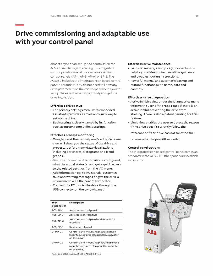
Almost anyone can set up and commission the ACS380 machinery drive using the integrated control panel or one of the available assistant control panels - AP-I, AP-S, AP-W, or BP-S. The ACS380 includes the integrated icon based control panel as standard. You do not need to know any drive parameters as the control panel helps you to set up the essential settings quickly and get the drive into action.
Effortless drive setup• The primary settings menu with embedded
assistants provides a smart and quick way to set up the drive.
• Each setting is clearly named by its function, such as motor, ramp or limit settings.
Effortless process monitoring• One glance at the control panel's editable home
view will show you the status of the drive and process. It offers many data visualizations including bar charts, histograms and trend graphs.
• See how the electrical terminals are configured, what the actual status is, and get a quick access to the related settings from the I/O menu.
• Add information eg, to I/O signals, customize fault and warning messages or give the drive a unique name with the panel’s text editor.
• Connect the PC tool to the drive through the USB connector on the control panel.
Type designation
Description
ACS-AP-I Assistant control panel
ACS-BP-S Assistant control panel
ACS-AP-WAssistant control panel with Bluetooth interface
ACS-BP-S Basic control panel
DPMP-01 Control panel mounting platform (flush mounted, requires also panel bus adapter on the drive)
DPMP-02 Control panel mounting platform (surface mounted, requires also panel bus adapter on the drive)
* Also compatible with ACS580 & ACS880 drives
—Drive commissioning and adaptable use with your control panel
Effortless drive maintenance• Faults or warnings are quickly resolved as the
help key provides context sensitive guidance and troubleshooting instructions.
• Powerful manual and automatic backup and restore functions (with name, date and content).
Effortless drive diagnostics• Active inhibits view under the Diagnostics menu
informs the user of the root-cause if there is an active inhibit preventing the drive from starting. There is also a patent pending for this feature.
• Limit view enables the user to detect the reason if the drive doesn’t currently follow the
reference or if the drive has not followed the
reference for the past 60 seconds.
Control panel optionsThe integrated icon based control panel comes as standard in the ACS380. Other panels are available as options.

16 AC S 3 8 0 TECH N I C A L C ATA LO G
When designing a machine, all necessary devices have to be compatible with each other to form a high-performing system level solution. Devices such as drives, programmable logic controllers (PLCs), motors, Human machine interfaces (HMIs), fieldbuses, safety functions and fieldbus connectivity need to be integrated seamlessly into one common system and to provide reliability, cost efficiency and flexibility for the entire design process.
All-compatible machinery drivesABB’s machinery drives have hundreds of hours of testing behind them. They are proven, meeting the high standards required for industrial automation. They connect smoothly to PLC’s through a wide range of available fieldbus protocols, enabling fast and secure communication between them. Inorder to control virtually any type of motor ABB’s machinery drives do this optimally and safely, saving energy and the environment at the same time. In order to access several drives and motors via the PLC there are various types of human machine interfaces such as drive control panels and touchscreen displays for fast and easy configuration. Safety functionality can be designed around or plugged into the drives and connected smoothly to a safety PLC.
—Connectivity and flexibility to meet your needs
Preconfigured fieldbus modulesFieldbus modules for the ACS380 drive preconfigure drive parameters to allow programming directly from the PLC.
Reliable solutionsABB machinery drives form with other automation devices a reliable and rapid connection that saves time and costs for the machine builder. Still, as everything is compatible, there must be flexibility to optimize the functionality of the machine. ABB also offers support and maintenance services for throughout the life cycle of the drives in the machine.

AC S 3 8 0 TECH N I C A L C ATA LO G 17
A fieldbus enables communication between drives and PLC systems, I/O devices and the process. Fieldbus communication reduces wiring costs when compared with traditional hard wired input/output connections. Fieldbus systems also offer the ability to gather large amounts of data which can then be utilized for improving the performance or safety of the machine.
The ACS380 configured variant is compatible with a wide range of fieldbus protocols. Fieldbus modules preconfigure drive parameter settings at power-up to allow programming directly from the PLC. The optional fieldbus adapter can be easily be mounted on the drive. The ACS380 standard variant comes with built-in Modbus RTU protocol.
Universal communication with ABB fieldbus adaptersThe machinery drives support the following fieldbus protocols:
Drive monitoringA set of drive parameters and/or actual signals, such as torque, speed, current, etc., can be selected for cyclic data transfer, providing fast data access.
Drive diagnosticsAccurate and reliable diagnostic information can be obtained through the alarm, limit and fault words, giving easy interfacing with plantwide HMIs.
CablingSubstituting the large amount of conventional drive control cabling and wiring with a single cable reduces costs and increases system reliability and flexibility.
DesignThe use of fieldbus control reduces engineering time at installation due to the modular structure of the hardware and software and the simplicity of the connections to the drives.
Commissioning and assemblyThe modular machine configuration allows precommissioning of single machine sections and provides easy and fast assembly of the complete installation.
Option code
Fieldbus protocol Adapter
+K454 PROFIBUS DP, DPV0/DPV1 FPBA-01-M
+K457 CANopen® FCAN-01-M
+K469 EtherCAT® FECA-01-M
+K475 Two port EtherNet/IP™, Modbus TCP, PROFINET IO
FENA-21-M
+K473 EtherNet/IP™, Modbus TCP, PROFINET IO
FENA-11
+K476 PowerLink FEPL-02
+K495 CANopen® BCAN-01
—Flexible connectivity to automation networks
18 AC S 3 8 0 TECH N I C A L C ATA LO G
64 Electrical installation
Fieldbus connection diagram
snoitpircseDslanimreTAux. voltage output and digital connectionsAux. voltage output +24 VDC, max. 250 mAAux. voltage output commonDigital input common for allDigital input 1: Stop (0)/Start (1)Digital input 2: Forward (0)/Reverse (1)Safe torque off (STO)Safe torque-off function. Connected at factory. Drive starts only when both circuits are closed. Refer to Safe torque off function on page 111.
Relay outputFault (-1)250 VAC/30 VDC2 AExtension module connectionsConnections depending on the product variant.
+24VDGNDDCOMDI 1DI 2
S+SGNDS 1S 2
RCRARB
DSUB9DSUB9
RJ45 X 2RJ45 X 2RJ45 X 2
RJ45
CANopenProfibus
EtherCATEthernet IP
ProfinetModbus TCP
Electrical installation 63
Default I/O connection diagram (ABB standard macro)
snoitpircseDslanimreTAux. voltage output and digital connectionsAux. voltage output +24 VDC, max. 250 mAAux. voltage output commonDigital input common for allDigital input 1: Stop (0)/Start (1)Digital input 2: Forward (0)/Reverse (1)Digital input 3: Speed selectionDigital input 4: Speed selectionDigital input function: Ramp set 1 (0)/Ramp set 2 (1)Digital output function: Ready to run (0)/Not ready (1)Signal cable shield (screen)Digital input common for allReference voltage and analog I/OOutput frequency/Speed reference (0...10 V)Analog input circuit commonNot configuredAnalog input circuit commonOutput frequency (0...20 mA)Analog output circuit commonSignal cable shield (screen)Reference voltageSafe torque off (STO)Safe torque-off function. Connected at factory. Drive starts only when both circuits are closed. Refer to Safe torque off function on page 111.
Relay outputFault (-1)250 VAC/30 VDC2 AEIA-485 Modbus RTUEmbedded Modbus RTU (EIA-485)
+24VDGNDDCOMDI 1DI 2DI 3DI 4DIO 1DIO 2DIO SRCDIO COM
AI 1AGNDAI 2AGNDAOAGNDSCR+10V
S+SGNDS 1S 2
RCRARB
B+A-BGNDShieldTermination
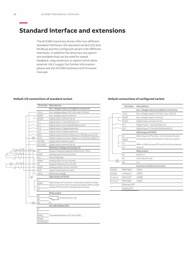
Terminals Descriptions
Aux. voltage output and digital connections
+24 V Aux. voltage output +24 V DC, max. 250 mA
DGND Aux. voltage output common
DCOM Digital input common for all
DI 1 Digital input 1: Stop (0)/Start (1)
DI 2 Digital input 2: Forward (0)/Reverse (1)
DI 3 Digital input 3: Speed selection
DI 4 Digital input 4: Speed selection
DIO 1 Digital input function: Ramp set 1 (0)/Ramp set 2 (1)
DIO 2 Digital output function: Ready to run (0)/Not ready (1)
DIO SRC Signal cable shield (screen)
DIO COM Digital input common for all
Reference voltage and analog I/O
AI 1 Output frequency/Speed reference (0...10 V)
AGND Analog input circuit common
AI 2 Not configured
AGND Analog input circuit common
AO Output frequency (0...20 mA)
AGND Analog output circuit common
SCR Signal cable shield (screen)
+10 V Reference voltage
Safe torque off (STO)
S+Safe torque-off function. Connected at factory. Drivestarts only when both circuits are closed. Refer to Safe torque off function in the hardware manual.
SGND
S 1
S 2
Relay output
RC No fault [Fault (-1)]
RA
RB
EIA-485 Modbus RTU
B+
Embedded Modbus RTU (EIA-485)
A-
BGND
Shield
Termination
DSUB9
DSUB9
RJ-45 x2
RJ-45 x2
Terminals Descriptions
Aux. voltage output and digital connections
+24 V Aux. voltage output +24 V DC, max. 250 mA
DGND Aux. voltage output common
DCOM Digital input common for all
DI 1 Digital input 1: Stop (0)/Start (1)
DI 2 Digital input 2: Forward (0)/Reverse (1)
Safe torque off (STO)
S+ Safe torque-off function. Connected at factory.
Drive starts only when both circuits are closed.
Refer to Safe torque off function in the hardware
manual.
SGND
S 1
S 2
Relay output
RC Fault (-1)
RA 250 V AC/30 V DC
RB 2 A
Extension module connections
PROFIBUS +K454
CANopen® +K457
EtherCAT® +K469
PROFINET +K475
Ethernet/IP™
ModbusTCP
Default I/O connections of standard variant
The ACS380 machinery drives offer two different standard interfaces: the standard variant (I/O and Modbus) and the configured variant with different interfaces. In addition the drive has one option slot available that can be used for speed feedback, relay extension or option which allow external +24 V supply. For further information please see the ACS380 hardware and firmware manuals.
Default connections of configured variant
—Standard interface and extensions

AC S 3 8 0 TECH N I C A L C ATA LO G 19
DSUB9
DSUB9
RJ-45 x2
RJ-45 x2
Brake chopperThe brake chopper is built-in as standard for the ACS380. Mechanical brake control is integrated into the ACS380 machinery drives. It uses state machine logic to control brake opening, closing, holding, wait and delay to integrate complex brake operation into the application.
—Brake options
Brake resistorThe brake resistors are separately available for the ACS380 machinery drives. Resistors other than the standard option resistors may be used, provided that the specified resistance value is within specified limits and that the heat dissipation capacity of the resistor is sufficient for the drive application (see hardware manual). No separate fuses in the brake circuit are required if the conditions for eg, the mains cable is protected with fuses and no mains cable/fuse overrating takes place.
The ACS380 machinery drives are equipped with a built-in filter to reduce high frequency emissions. Low EMC filters (C3 for 200V and C4 for 400V) are standard on ACS380-040X drives. High EMC filters (C2 for all voltages are denoted by type codes ACS380-042X.
EMC standardsThe EMC product standard (EN 61800-3) covers the specific EMC requirements stated for drives (tested with motor and cable) within the EU. EMC standards such as EN 55011 or EN 61000-6-3/4 are applicable to industrial and domestic equipment and systems including components inside the drive. Drive units complying with the requirements of EN 61800-3 are compliant with comparable categories in EN 55011 and EN 61000-6-3/4, but not necessarily vice versa. EN 55011 and EN 61000-6-3/4 do not specify cable length or require a motor to be connected as a load. The emission limits are comparable to EMC standards according to the table below.
EMC - electromagnetic compatibilityDomestic environments versus public low voltage networks1st environment includes domestic premises. It also includes establishments directly connected without an intermediate transformer to a low voltage power supply network that supplies buildings used for domestic purposes. 2nd environment includes all establishments directly connected to public low voltage power supply networks.
Comparison of EMC standards
EMC according to EN 61800-3product standard
EN 61800-3product standard
EN 55011, product family standard for industrial, scientific and medical (ISM) equipment
EN 61000-6-4, generic emission standard for industrial environments
EN 61000-6-3, genericemission standard forresidential, commercial and light-industrial environment
1st environment, unrestricted distribution Category C1 Group 1, Class B Not applicable Applicable
1st environment, restricted distribution Category C2 Group 1, Class A Applicable Not applicable
2nd environment, unrestricted distribution Category C3 Group 2, Class A Not applicable Not applicable
2nd environment, restricted distribution Category C4 Not applicable Not applicable Not applicable

20 AC S 3 8 0 TECH N I C A L C ATA LO G
Manage your drives and the process lines and machines they control
Easy access to cloud-based drive and process information from anywhere via online connection
Start-up, commission and tune your drive and application
Simplified user interface with instant access to drive status and configuration
Performance optimization via drive troubleshooting features and fast support.
Drivetune
—Save time and improve drive performance with ABB's Drivetune app
Easy and fast access to product information and support
Access information anywhere Download the Drivetune app via QR codes or directly from the app stores.

AC S 3 8 0 TECH N I C A L C ATA LO G 21
The future of your drives depends on the service you choose. Whatever you choose, it should be a well-informed decision. No guesswork. We have the expertise and experience to help you find and implement the right service for your drive equipment. You can start by asking yourself these two critical questions:
• Why should my drive be serviced?• What would my optimal service options be?
From here, you have our guidance and full support along the course you take, throughout the entire lifetime of your drives.
Service to match your needs
Your choice, your business efficiencyABB Drive Care agreement lets you focus on your core business. A selection of predefined service options matching your needs provides optimal, more reliable performance, extended drive lifetime and improved cost control. So you can reduce the risk of unplanned downtime and find it easier to budget for maintenance.
We can help you more by knowing where you are!Register your drive at www.abb.com/drivereg for extended warranty options and other benefits.
Your service needs depend on your operation, life cycle of your equipment and business priorities. We have identified our customers’ four most common needs and defined service options to satisfy them. What is your choice to keep your drives at peak performance?
Rapid response
Example services include:• Technical Support• Drive Exchange• On-Site Repair• Spare Parts• •Training
Life cycle management
Example services include:• Preventive Maintenance• Hardware Upgrades• Control Upgrades• Retrofits
Performance improvement
Example services include:• Drive Care Agreement• Training• Preventive Maintenance• Hardware Upgrades• Control Upgrades• Retrofits• Workshop Repair
Operational efficiency
Example services include:• Drive Care Agreement• Commissioning• Spare Parts• Preventive Maintenance• Drive Exchange
—Drive ServicesYour choice, your future

22 AC S 3 8 0 TECH N I C A L C ATA LO G
Keeping you informedWe notify you every step of the way using life cycle status statements and announcements. Your benefit is clear information about your drives’ status and precise services available. It helps you plan the preferred service actions ahead of time and make sure that continuous support is always available.
Product is in active sales and manufacturing phase.
Full range of life cycle services is available.
Full range of life cycle services is available. Product enhancements may be available through upgrade and retrofit solutions.
Limited range of life cycle services is available. Spare parts availability is limited to available stock.
Product is no longer available.
Product is no longer available.
Active Classic Limited Obsolete
ABB drives life cycle phases explained:
Full range of life cycle services and supportLimited range of life cycle services and support
Replacement and end-of-life services
Serial production has ceased. Product may be available for plant extensions, as a spare part or for installed base renewal.
Product
ServicesReplacement and end-of-life services are available.
Life Cycle Status AnnouncementProvides early information about the upcoming life cycle phase change and how it affects the availability of services.
Life Cycle Status StatementProvides information about the drive's current life cycle status, availability of product and services, life cycle plan and recommended actions.
Step 1
Step 2
Now it’s easy for you to see the exact service and maintenance available for your drives.
You are in control of every life cycle phase of your drives. At the heart of drive services is a four-phase product life cycle management model. This model defines the services recommended and available throughout the drive's lifespan.
—Drive ServicesA lifetime of peak performance

AC S 3 8 0 TECH N I C A L C ATA LO G 23
Additional informationWe reserve the right to make technical changes or modify the contents of this document without prior notice. With regard to purchase orders, the agreed particulars shall prevail. ABB AG does not accept any responsibility whatso-ever for potential errors or possible lack of information in this document.
We reserve all rights in this document and in the subject matter and illustra-tions contained therein. Any reproduc-tion, disclosure to third parties or utilization of its contents – in whole or in parts – is forbidden without prior written consent of ABB AG.

—ABB, Inc16250 W. Glendale DriveNew Berlin, WI 53151
abb.com/drives
AC
S38
0-P
HT
C0
1U-E
N R
EVA
Eff
ecti
ve: 0
4/0
1/20
17. S
ub
ject
to
ch
ang
e w
ith
ou
t n
oti
ce. A
ll ri
gh
ts r
eser
ved
.
© Copyright 2017 ABB. All rights reserved. Specifications subject to change without notice.