Cardinal-Hickory Creek 345-kV Transmission Line Project125 miles of 345-kV transmission line and...
169
Cardinal-Hickory Creek 345-kV Transmission Line Project FINAL ENVIRONMENTAL IMPACT STATEMENT Volume I Chapters 1- 2 October 2019 Prepared for: U.S. Department of Agriculture, Rural Utilities Service Cooperating Agencies: U.S. Army Corps of Engineers U.S. Fish and Wildlife Service U.S. Environmental Protection Agency
Transcript of Cardinal-Hickory Creek 345-kV Transmission Line Project125 miles of 345-kV transmission line and...

Cardinal-Hickory Creek 345-kV Transmission Line Project
FINAL ENVIRONMENTAL IMPACT STATEMENT
Volume I Chapters 1- 2
October 2019
Prepared for:U.S. Department of Agriculture,
Rural Utilities Service
Cooperating Agencies:U.S. Army Corps of EngineersU.S. Fish and Wildlife Service
U.S. Environmental Protection Agency


Cardinal-Hickory Creek 345-kV Transmission Line Project Responsible Federal Agency (Lead): U.S. Department of Agriculture, Rural Utilities Service
Cooperating Agencies: U.S. Army Corps of Engineers, U.S. Fish and Wildlife Service, U.S. Environmental Protection Agency
Title: Cardinal-Hickory Creek 345-kV Transmission Line Project Final Environmental Impact Statement
Location: Eastern Iowa, southwestern and south-central Wisconsin
Contacts
For further information about this environmental impact statement, contact:
Dennis Rankin Project Manager USDA, Rural Utilities Service Engineering and Environmental Staff 1400 Independence Avenue, SW Stop 1571, Room 2244 Washington, D.C. 20250-1571 (202) 720-1953 [email protected]
For general information on RUS’s process for implementing the National Environmental Policy Act, contact:
Barbara Britton Director, Water Programs Division Water and Environmental Programs USDA, Rural Utilities Service 1400 Independence Avenue, SW Stop 1571, Room 2244 Washington, D.C. 20250-1571 (202) 720-1649 [email protected]

DEAR READER: Enclosed is the final environmental impact statement (EIS) for the Cardinal-Hickory Creek Project (C-HC Project). This EIS has been prepared by the U.S. Department of Agriculture (USDA), Rural Utilities Service (RUS) in accordance with the Council on Environmental Quality regulations at Title 40 Code of Federal Regulations 1500–1508; the National Environmental Policy Act of 1969; the Rural Electrification Act of 1936, as amended; and other applicable laws and policies. RUS is the lead agency and has prepared this document in consultation with the U.S. Army Corps of Engineers (USACE), U.S. Fish and Wildlife Service (USFWS), and U.S. Environmental Protection Agency (USEPA) as cooperating agencies.
General Information
The final EIS (FEIS) has been prepared to analyze the potential impacts of RUS providing financial assistance to Dairyland Power Cooperative for their partial ownership and participation in a new 345- kilovolt (kV) transmission line between Dane County, Wisconsin, and Dubuque County, Iowa, the C-HC Project. The USACE must decide whether or not to issue authorizations and permits to allow the C-HC Project to be constructed. The USFWS must decide whether or not to issue permits and easements to allow the C-HC Project to cross the Upper Mississippi River National Wildlife and Fish Refuge.
Dairyland Power Cooperative, American Transmission Company LLC, and ITC Midwest LLC (hereafter the Utilities) propose to construct and own a new 345-kV transmission line between Dane County, Wisconsin, and Dubuque County, Iowa. The Utilities propose to construct approximately 100 to 125 miles of 345-kV transmission line and interconnecting 345-kV network facilities. The proposal also includes a new intermediate substation near Montfort, Wisconsin, which would provide connectivity to the regional 345-kV network.
The C-HC Project would increase the capacity of the regional transmission system to meet the following needs:
• Address reliability issues on the regional bulk transmission system and ensure a stable and continuous supply of electricity is available to be delivered where it is needed even when facilities (e.g., transmission lines or generation resources) are out of service.
• Alleviate congestion that occurs in certain parts of the transmission system and thereby remove constraints that limit the delivery of power from where it is generated to where it is needed to satisfy end-user demand.
• Expand the access of the transmission system to additional resources, including 1) lower-cost generation from a larger and more competitive market that would reduce the overall cost of delivering electricity, and 2) renewable energy generation needed to meet state renewable portfolio standards and support the nation’s changing electricity mix.
• Increase the transfer capability of the electrical system between Iowa and Wisconsin.
• Reduce the losses in transferring power and increase the efficiency of the transmission system and thereby allow electricity to be moved across the grid and delivered to end-users more cost-effectively.
2
• Respond to public policy objectives aimed at enhancing the nation’s transmission system and to support the changing generation mix by gaining access to additional resources such as renewable energy or natural gas-fired generation facilities.
Changes Between Draft and Final Environmental Impact Statements
The purpose of this summary is to identify the substantial revisions made to the C-HC Project EIS between the draft EIS (DEIS) and FEIS. These revisions were made to respond to public and agency comments received during the DEIS public review period and incorporate additional information analyzed by RUS and cooperating agencies to inform potential impacts to the human and natural environment.
General Revisions • Revisions were made to the FEIS to improve readability, correct typos, and improve consistent
presentation of information throughout the document.
• Maps were updated to reflect minor changes in the alternative alignments in Iowa and to include the Lancaster and Hillman Substations.
Appendices • New appendices were added to the FEIS:
o Appendix F. Draft Environmental Impact Statement Public Comment Report
o Appendix G. U.S. Fish and Wildlife Service Biological Opinion
o Appendix H. Programmatic Agreement
o Appendix I. Federal Mitigation Plan
o Appendix J: U.S. Fish and Wildlife Service Compatibility Determination for the Upper Mississippi River National Wildlife and Fish Refuge
Chapter 1 • In Section 1.3, information was added to more thoroughly explain the Federal Energy Regulatory
Commission’s planning processes.
• In Section 1.4, information was added to describe in more detail electricity flow and the transfer capability between Iowa and Wisconsin.
• In Section 1.7, two new sections were inserted to provide information on the public comment period and comments received for the DEIS.
Chapter 2 • In Section 2.4, project elements that were previously identified as connected actions in the DEIS
were incorporated into the description of the C-HC Project.
o Information was added to include the Lancaster and Hillman Substations as part of the C-HC Project, and additional information about the modifications needed for the Turkey River Substation was added.

3
o Information was added to provide a detailed description of the process that would be used to retire and decommission the N-9 transmission line.
• In Section 2.4, clarification was added on blasting procedures for the C-HC Project.
• In Section 2.4, additional details were added on how the right-of-way would be maintained and on vegetation management practices.
• A new section, Section 2.6, was added to disclose the Agency Preferred Alternative.
• A new section, Section 2.7, was added to disclose the Environmentally Preferable Alternative.
Chapter 3 • Various sections were added throughout the chapter to integrate the impact analysis for the
retirement and decommissioning of the N-9 transmission line that crosses the Upper Mississippi River National Wildlife and Fish Refuge.
• In Section 3.1, the environmental commitments were updated, and additions were made to reflect ongoing discussions with cooperators, the issuance of the USFWS biological opinion, and the Utilities’ applications to the Wisconsin Public Service Commission.
EIS Section 3.3, Vegetation, including Wetlands and Special Status Plants • Information was added to the affected environment to more thoroughly describe the pine relicts
that potentially occur in the analysis area and to describe the location of a known state-listed fern species, Asplenium pinnatifidum.
• Context was added to the landcover analysis by providing percentages of landcover impacted for each alternative.
EIS Section 3.4, Wildlife, including Special Status Species • Information was added throughout the section to provide the updated data for the rusty patched
bumble bee (Bombus affinis) and to pull in relevant information and environmental commitments from the USFWS biological opinion.
• Additional data from the National Audubon’s Christmas Bird Count database and bald eagle (Haliaeetus leucocephalus) data from the Wisconsin Department of Natural Resources were added.
• Context was added to the habitat analysis by providing percentages of habitats impacted for each alternative.
EIS Section 3.5, Water Resources and Quality • Updated information regarding Wisconsin Outstanding Resource Waters or Exceptional Resource
Waters was added.
• Details were added to more thoroughly describe the trout streams present in the analysis area.
• An analysis was added to describe specific impacts to groundwater flow through karst features.
EIS Section 3.6, Air Quality and Climate Change • Information was added to describe the potential climate change effects resulting from landcover
changes due to construction activities such as clearing woodlands. An impact analysis was added

4
to present the potential impacts of the C-HC Project and associated removal of forest vegetation on climate change and carbon sequestration.
EIS Section 3.7, Noise • Discussions of noise impacts associated with potential blasting as well as impacts from
construction noise on livestock were added.
EIS Section 3.8, Transportation • Information regarding Wisconsin Rustic Roads present in the analysis area was added.
EIS Section 3.9, Cultural and Historic Resources • Updates were added to provide current status of the tribal consultation process.
• The impact analysis was updated to include the impacts from the laydown yards.
• The Nelson Dewey Plantation (historic home site) was identified as occurring within the area of potential effects for the C-HC Project.
EIS Section 3.10, Land Use, including Agriculture and Recreation • Information was added throughout the section to provide more detail regarding USDA Natural
Resources Conservation Service Conservation Reserve Program–enrolled lands and Wisconsin Managed Forest Law–enrolled lands and impacts to these lands.
• Information was added to describe forested areas managed for timber production and potential impacts to timber production from the C-HC Project.
• The Southwest Wisconsin Grassland and Stream Conservation Area was identified as a natural area that occurs within the analysis area, and a subsequent impact analysis was added throughout the various subsections.
• Information was added to clarify impacts to loss of agricultural lands from power line tower structures.
• Potential impacts to organic farming from herbicide drift were added.
EIS Section 3.11, Visual Quality and Aesthetics • Information was added to more thoroughly describe the Ice Age National Scenic Trail within the
analysis area.
• Visual simulations were updated with photograph details such as distance to nearest structure, and photographs from existing structures similar to the C-HC Project were added.
EIS Section 3.12, Socioeconomics and Environmental Justice • U.S. Census data were reviewed at a finer scale to analyze potential impacts to environmental
justice communities. Sections were revised to describe environmental justice communities using minority group populations and poverty levels at the census-tract level. Furthermore, the USEPA environmental justice screening tool was used to inform the affected environments for the seven environmental justice communities in the analysis area. Impact analyses were updated using the new datasets.

5
• The impact analysis regarding property values in the analysis area was updated based on new information received between the DEIS and FEIS.
EIS Section 3.13, Public Health and Safety • Citations were added to address public comments that expressed concerns about potential links
between public health and exposure to electric and magnetic fields.
• Updates were added to include additional types of severe weather events and to address security breaches.
• Information was added to describe stray voltage.
• Updates were added to disclose potential impacts to livestock from exposure to electric and magnetic fields.
• Information was added regarding dispersal of charged particles and the potential impacts to individuals’ health.
Chapter 4 • The revisions to the cumulative impacts analysis include better-defined spatial boundaries that are
commensurate with the context and intensity of direct and indirect effects from the C-HC Project.
o The Nemadji Trail Energy Center project remains in Chapter 4; however, the project falls outside the spatial boundaries for cumulative analysis; therefore, the project is not analyzed for cumulative effects.
• The revisions to the cumulative impacts analysis also include a more-refined cumulative action scenario, which is a term used to refer to past, present, and reasonability foreseeable projects considered in cumulative impact analysis. RUS identified potential projects and developments in the redefined spatial boundaries, which include additional areas in Illinois, Iowa, and Wisconsin.
o Types of projects included in the cumulative scenario are other energy projects, transportation projects, development projects receiving Federal or state funds and/or have received appropriate Federal or state permits, and large conservation projects by state or local agencies within the spatial boundaries.
o Projects were included in the cumulative action scenario if they were judged to be large enough in magnitude, in terms of size and scale, to potentially impact the same type and amount of resources that would be impacted by the C-HC Project, as disclosed in Chapter 3.
• A new subsection under the Air Quality and Climate Change section was added to include a discussion of the cumulative impacts to climate change. For this analysis, RUS reviewed two different electricity generation sources (coal-fired generation and wind-powered generation) to estimate a range of carbon dioxide emissions from electricity generation sources that could have access to transmission from the C-HC Project. These carbon dioxide emission estimates were used to evaluate potential cumulative climate change impacts.

6
Chapter 5 • Status updates were added for project consultations and coordination with various groups.
Final Environmental Impact Statement Availability The FEIS and supporting documents are available at the locations listed in Chapter 8 and online:
https://www.rd.usda.gov/publications/environmental-studies/impact-statements/cardinal-%E2%80%93-hickory-creek-transmission-line.
The FEIS will be available for a 30-day public review period upon the publishing of the Notice of Availability (NOA) in the Federal Register.
Public comments will be accepted in the following ways:
1. Email your comments to: [email protected]
2. Mail your written comments to: SWCA Environmental Consultants, Attn: Cardinal-Hickory Creek EIS, 80 Emerson Lane, Suite 1306, Bridgeville, PA 15017.
Comments will be accepted through the 30-day public review period listed in the NOA.
Any person wishing to be added to the mailing list of interested parties may write or call the project manager at this address or telephone number.
Sincerely,
Dennis Rankin Project Manager USDA, Rural Utilities Service Engineering and Environmental Staff 1400 Independence Avenue, SW Stop 1571, Room 2244 Washington, D.C. 20250-1571 (202) 720-1953 [email protected]
EXECUTIVE SUMMARY
Introduction Dairyland Power Cooperative (Dairyland), American Transmission Company LLC (ATC), and ITC Midwest LLC (ITC Midwest), together referred to as “the Utilities,” propose to construct and own a new 345-kilovolt (kV) transmission line between Dane County, Wisconsin, and Dubuque County, Iowa.
The approximately 100- to 125-mile 345-kV transmission line is proposed between Dane County, Wisconsin, and Dubuque County, Iowa. The proposed project includes the following facilities:
• At the existing Cardinal Substation in Dane County, Wisconsin: a new 345-kV terminal within the substation;
• At the proposed Hill Valley Substation near the village of Montfort, Wisconsin: an approximately 22-acre facility with five 345-kV circuit breakers, one 345-kV shunt reactor, one 345-/138-kV autotransformer, and three 138-kV circuit breakers;
• At the existing Eden Substation near the village of Montfort, Wisconsin: transmission line protective relaying upgrades to be compatible with the new protective relays installed at the new Hill Valley Substation and replacement of conductors and switches to meet Utilities’ operating limits;
• Between the existing Eden Substation and the proposed Hill Valley Substation near the village of Montfort, Wisconsin: a rebuild of the approximately 1 mile of Hill Valley to Eden 138-kV transmission line;
• At the existing Wyoming Valley Substation near Wyoming, Wisconsin: installation of nine 16-foot ground rods to mitigate potential fault current contributions from the proposed project;
• Between the existing Cardinal Substation and the proposed Hill Valley Substation: a new 50- to 53-mile (depending on the final route) 345-kV transmission line;
• Between the proposed Hill Valley Substation and existing Hickory Creek Substation: a new 50- to 70-mile (depending on the final route) 345-kV transmission line;
• At the Mississippi River in Cassville, Wisconsin: a rebuild and possible relocation of the existing Mississippi River transmission line crossing to accommodate the new 345-kV transmission line and Dairyland’s 161-kV transmission line, which would be capable of operating at 345-/345-kV but would initially be operated at 345-/161-kV;
o depending on the final route and the Mississippi River crossing location: • a new 161-kV terminal and transmission line protective relaying upgrades within
the existing Nelson Dewey Substation in Cassville, Wisconsin; • a replaced or reinforced structure within the Stoneman Substation in Cassville,
Wisconsin;
• Multiple, partial, or complete rebuilds of existing 69-kV, 138-kV, and 161-kV transmission lines in Wisconsin that would be collocated with the new 345-kV line;
• At the existing Turkey River Substation in Clayton County, Iowa: one new 161-/69-kV transformer, three new 161-kV circuit breakers, and four new 69-kV circuit breakers; and
• At the existing Hickory Creek Substation in Dubuque County, Iowa: a new 345-kV terminal within the existing Hickory Creek Substation.

Cardinal-Hickory Creek 345-kV Transmission Line Project FEIS
ES-2
These upgrades and new construction projects are all together referred to as the “Cardinal-Hickory Creek Project” (or the “C-HC Project”). Due to the scope and potential impact of the C-HC Project and the involvement and actions of certain Federal agencies, an environmental impact statement (EIS) is being prepared to fulfill obligations specified under the National Environmental Policy Act (NEPA).
Dairyland intends to request financial assistance from the U.S. Department of Agriculture Rural Utilities Service (RUS) to fund its anticipated 9% ownership interest in the C-HC Project. RUS administers programs that provide much-needed infrastructure or infrastructure improvements to rural communities. RUS’s evaluation to potentially finance the Dairyland portion of the C-HC Project constitutes a Federal action, requiring it to perform an environmental review within the context of NEPA. To comply with NEPA, RUS has prepared this final EIS (FEIS) to inform the determination of whether RUS funds should be obligated to finance Dairyland’s ownership portion of the project prior to initiation of construction.
RUS is serving as the lead Federal agency for the NEPA environmental review of the C-HC Project. The U.S. Fish and Wildlife Service (USFWS), U.S. Army Corps of Engineers (USACE), and U.S. Environmental Protection Agency (USEPA) are cooperating agencies for the FEIS. The National Park Service is serving as a participating agency. Regardless of the potential financial assistance from RUS to fund Dairyland’s ownership interest in the C-HC Project, a NEPA environmental review would still be required as part of the permitting actions by USACE, USFWS, and potentially other Federal agencies.
Project Purpose and Need In many areas of the Midwest, the electricity transmission backbone system primarily consists of 345-kV lines. There are limited connection points to the existing regional grid and 345-kV transmission lines in the area from northeast Iowa and southwestern and south-central Wisconsin. The Utilities propose to construct and own the C-HC Project 345-kV transmission line and interconnecting 345-kV network facilities in northwest Iowa and south-central Wisconsin. The C-HC Project is the southern portion of Midcontinent Independent System Operator, Inc.’s (MISO’s) multi-value project (MVP) #5 project. The proposal includes a new intermediate substation near Montfort, Wisconsin, which would provide connectivity to the regional 345-kV network.
The C-HC Project would increase the capacity of the regional transmission system to meet the following needs:
• Address reliability issues on the regional bulk transmission system and ensure a stable and continuous supply of electricity is available to be delivered where it is needed even when facilities (e.g., transmission lines or generation resources) are out of service;
• Alleviate congestion that occurs in certain parts of the transmission system and thereby remove constraints that limit the delivery of power from where it is generated to where it is needed to satisfy end-user demand;
• Expand the access of the transmission system to additional resources, including 1) lower-cost generation from a larger and more competitive market that would reduce the overall cost of delivering electricity, and 2) renewable energy generation needed to meet state renewable portfolio standards and support the nation’s changing electricity mix;
• Increase the transfer capability of the electrical system between Iowa and Wisconsin;
• Reduce the losses in transferring power and increase the efficiency of the transmission system and thereby allow electricity to be moved across the grid and delivered to end-users more cost-effectively; and

Cardinal-Hickory Creek 345-kV Transmission Line Project FEIS
ES-3
• Respond to public policy objectives aimed at enhancing the nation’s transmission system and to support the changing generation mix by gaining access to additional resources such as renewable energy or natural gas-fired generation facilities.
Federal Purpose and Need Several agencies will use this FEIS to inform decisions about funding, authorizing, or permitting various components of the proposed C-HC Project:
• RUS, the lead Federal agency, will evaluate whether or not to provide financial assistance for Dairyland’s portion of the project.
• USFWS will evaluate the Utilities’ request for a right-of-way (ROW) easement and a Special Use Permit to cross the Upper Mississippi River National Wildlife and Fish Refuge (Refuge).
• USACE will review a ROW request as well as permit applications and requests for permission by the Utilities, as required by Section 10 and Section 408 of the Rivers and Harbors Act and Section 404 under the Clean Water Act.
Certificate of Public Convenience and Necessity in Wisconsin and Electric Transmission Franchise in Iowa In addition to compliance with all applicable Federal regulations, a certificate of public convenience and necessity (CPCN) must be granted by the State of Wisconsin and an electric transmission franchise granted by the State of Iowa. The Public Service Commission of Wisconsin (PSCW) is responsible for reviewing and approving applications for a transmission project that is either 1) 345 kV or greater, or 2) less than 345 kV but greater than or equal to 100 kV, over 1 mile in length, and needing a new ROW (PSCW 2017). The Utilities’ CPCN application for the C-HC Project was deemed completed by the PSCW on October 4, 2018. The PSCW issued their Draft EIS for the C-HC Project on February 28, 2019, and the Final EIS on May 8, 2019. Projects for which an EIS is prepared always require a public hearing in the project area (PSCW 2017). The PSCW held public hearings for C-HC Project on June 25 through 27, 2019. The Iowa Utilities Board (IUB) is responsible for reviewing and processing all petitions for electric transmission line franchises under Iowa Code Chapter 478 – Electric Transmission Lines, Chapter 11 of 199 Iowa Administrative Code – Electric Lines, and Chapter 25 of 199 Iowa Administrative Code – Iowa Electrical Safety Code. A franchise is the authorization of the IUB for the construction, erection, maintenance, and operation of an electric transmission line. The granting of a franchise requires a finding by the IUB that the project is necessary to serve a public use, represents a reasonable relationship to an overall plan of transmitting electricity in the public interest, and meets all other legal requirements (IUB 2017). The Utilities held two informational meetings for the C-HC Project on March 29, 2018. The Utilities submitted the petition to the IUB for the C-HC Project on May 11, 2018. The IUB public hearing is scheduled for December 10–12, 2019.
Public Involvement Throughout the NEPA process, the public and various government agencies have had the opportunity to provide input and comment on the C-HC Project. The Notice of Intent published on October 18, 2016, initiated the 30-day public scoping period, which ultimately was extended to 81 days ending on January 6, 2017. The announcement included a brief overview about the Proposed Action and alternatives, potential resource concerns, opportunities to provide input and attend meetings, and RUS project contacts.

Cardinal-Hickory Creek 345-kV Transmission Line Project FEIS
ES-4
Letters, radio public service announcements, and newspaper advertisements announcing the proposed project, and the scoping meeting locations and times were distributed prior to the public scoping meetings. RUS held six public scoping meetings to present the RUS NEPA process and timelines, and to answer questions and receive comments regarding the C-HC Project.
RUS also sent letters to Federal and state agencies and federally recognized tribes with interest in the C-HC project area inviting them to participate in public and agency scoping meetings concurrently with the public scoping meetings in October and November 2016. Tribes were invited to participate in the National Historic Preservation Act (NHPA) Section 106 review process, attend public scoping meetings, and provide relevant information for inclusion in the draft EIS (DEIS).
Scoping During scoping, RUS received 379 comment letters from 352 commenters for a total of 1,736 individual comments. The key issues identified during the comment process were primarily related to socioeconomics, NEPA process, wildlife, land use, and visual resources. A summary of the public comments received and organized by concern, issue, or resource topic is presented in Table ES-1 in order of the greatest number of comments received to the fewest number of comments received.
Table ES-1. Scoping Comment Summary by Topic
Topic Number of Comments Topic Number of Comments
Socioeconomics 552 Impact Analyses 51
NEPA Process 481 Cultural Resources 39
Wildlife 262 Air Quality 30
Land Use 169 Public Involvement 29
Visual Resources 162 Geology 28
Recreation and Natural Areas 116 Soils 19
Water Resources 112 Transportation 16
Vegetation 112 Noise 14
Public Health and Safety 71 Communications Infrastructure 5
Decision Process 61 Paleontology 1
Public Comment Period RUS held six public meetings on the DEIS during which interested parties made oral comments in a formal setting and/or submitted written comments (Table ES-2). A court reporter was present to record these oral comments. Meeting transcripts are available on the project website.
Table ES-2. DEIS Public Meeting Dates, Times, and Locations
Date Location Meeting Time Venue
March 13, 2019 Dodgeville, Wisconsin 5:00–7:00 p.m. Dodger Bowl Banquet Hall 318 King Street Dodgeville, WI 53533

Cardinal-Hickory Creek 345-kV Transmission Line Project FEIS
ES-5
Date Location Meeting Time Venue
March 14, 2019 Barneveld, Wisconsin 5:00–7:00 p.m. Deer Valley Lodge 401 West Industrial Drive Barneveld, WI 53507
March 15, 2019 Guttenberg, Iowa 5:00–7:00 p.m. Guttenberg Municipal Building 502 S. First Street Guttenberg, IA 52052
March 18, 2019 Cassville, Wisconsin 5:00–7:00 p.m. Cassville Middle School Cafeteria 715 E. Amelia Street Cassville, WI 53806
March 19, 2019 Peosta, Iowa 5:00–7:00 p.m. Peosta Community Center 7896 Burds Road Peosta, IA 53068
March 20, 2019 Middleton, Wisconsin 5:00–7:00 p.m. Madison Marriott West 1313 John Q Hammons Drive Middleton, WI 53562
A total of 401 comment submittals (letters, emails, commenters at hearings) was provided to RUS on the DEIS; within the submittals, there were 2,686 individual comments. Seven of these 401 comment letters were duplicate letters, and 54 were form letters or a variation of a form letter. All comments that were received became a part of the administrative record and were entered into an interactive, searchable table and coded to reflect the subject matter of concern, sorted, and summarized. Appendix F of the FEIS includes all DEIS comments and agency responses to these comments in tabular format.
RUS has reviewed the 2,039 individual comments contained within the comment letters (excluding duplicates and form letter copies). A summary of the public comments received and organized by concern, issue, or resource topic is presented in Table ES-3, in order of the greatest number of comments received to the least number of comments received. It is possible that comments addressed multiple topics; therefore, comments may be included in multiple topics below. In addition, there were 17 comments requesting additional information/maps or meetings, six comments that referenced other projects, nine editorial comments, four comments that cited literature that should be reviewed for the C- HC Project EIS, and 25 comments that required no further response. RUS has reviewed all the comments received and responded to all comments in Appendix F. RUS has revised the FEIS to address and respond to comments, where appropriate.
Table ES-3. Summary of DEIS Comments Received, by Topic
Topic Number of Comments
Socioeconomics 537
Alternatives 388
NEPA/Purpose and Need 292
Wildlife 189
Vegetation 188
Land Use 179
Decision Process 155
Visual Resources 140
Public Health and Safety 129
Effects Analysis 128

Cardinal-Hickory Creek 345-kV Transmission Line Project FEIS
ES-6
Topic Number of Comments
Recreation 93
Water Resources 67
Air Quality/Climate Change 52
Public Involvement 39
Soil 36
Cultural Resources 30
Transportation 18
Noise 16
Geology 10
Total 2,686
Proposed Project and Alternatives RUS regulations (7 CFR 1970.5 (b)(3)(iii)) require the Utilities to “develop and document reasonable alternatives that meet their purpose and need while improving environmental outcomes.” As part of the initial investigation of the proposed C-HC Project, the Utilities prepared three corridor-siting documents: the Alternatives Evaluation Study (AES) (Dairyland et al. 2016a), the Alternative Crossings Analysis (ACA) (Burns and McDonnell Engineering Company [Burns and McDonnell] 2016), and the Macro-Corridor Study (MCS) (Dairyland et al. 2016b). The AES describes the transmission planning process and modeling scenarios used by MISO to evaluate electrical alternatives and to identify the project endpoints: the Hickory Creek Substation in Iowa, and the Cardinal Substation in Wisconsin. The Utilities then developed the C-HC Study Area to develop a range of reasonable route alternatives connecting the two endpoints. Once the boundaries of the C-HC Study Area were defined, the Utilities identified potential macro-corridors within the C-HC Study Area by completing an opportunities-and-constraints analysis using the results from field reconnaissance and geographic information system (GIS) databases.
Alternatives Considered but Not Evaluated in Detail
Alternative transmission line corridors in Wisconsin were identified and investigated by the Utilities during the initial routing studies. In addition, Mississippi River crossing alternatives were investigated and determined to be not feasible. The alternative corridors discussed in this section were not carried forward for detailed analysis in this FEIS for a variety of reasons. The following alternatives in the Cardinal Substation to Hill Valley Substation Area, Hill Valley Substation to Mississippi River Study Area, and Alternative Mississippi River Crossings were eliminated from detailed analysis: Alternative Corridors 1–12, Lock and Dam No. 10, Lock and Dam No. 11, Highway 61/151 crossing in Dubuque, Iowa (Highway 151 Bridge), Julien Dubuque Bridge/Highway 20 crossing in Dubuque, Iowa (Julien Dubuque Bridge), and Dubuque to Galena 161-kV Transmission Line crossing in Dubuque, Iowa (Galena 161-kV Transmission Line).
In addition, the Utilities examined alternative routes for crossing the Refuge. The Utilities have met with the USFWS since April 2012 to discuss potential Mississippi River crossings, including crossings of the Refuge. The Utilities provided an ACA report to demonstrate that non-Refuge alternatives were not economically or technically feasible and would have greater overall environmental and human impacts compared to the feasible Refuge crossing locations (Burns and McDonnell 2016).

Cardinal-Hickory Creek 345-kV Transmission Line Project FEIS
ES-7
Non-transmission alternatives reviewed for this FEIS include regional or local renewable electricity generation (i.e., solar), energy storage, energy efficiency, and demand response. In addition, RUS also considered two transmission line alternatives, a lower-voltage alternative and underground burial of the transmission line. The non-transmission, lower-voltage and underground alternatives were evaluated on the six-point need for the Proposed Action, but were not carried forward for detailed analysis.
The No Action Alternative
The No Action Alternative “provides a benchmark, enabling decision makers to compare the magnitude of environmental effects of the action alternatives” (CEQ 1981: Question 3) (40 CFR 1502.14). The No Action Alternative provides the environmental baseline against which the other alternatives are compared (RUS regulation 7 CFR 1970.6 (a)).
Under the No Action Alternative, RUS would not provide funding for Dairyland’s portion of the C-HC Project, and the USFWS and USACE would not grant the ROWs necessary for the C-HC Project to cross the Refuge. The project would not be built, and existing land uses and present activities in the analysis area would continue.
Action Alternatives
RUS has identified six alternatives for the C-HC Project. These alternatives consist of individual route segments that, when combined, form complete route alternatives connecting the Cardinal Substation in Wisconsin with the Hickory Creek Substation in Iowa. Figure ES-1 shows the segments used to develop the six action alternatives for the C-HC Project.
The estimated total cost for the proposed C-HC Project is $500 million to $550 million (in 2023 dollars), depending on the alternative selected. Dairyland intends to request financial assistance from RUS to fund its anticipated 9% ownership interest in the C-HC Project. If approved, the in-service date would be scheduled for 2023.
Overall, for all the alternatives, in places where the proposed transmission line is collocated with existing transmission lines, the lines would be installed with a double-circuit configuration on new transmission line structures, and the existing transmission line ROW would be used to accommodate the new structures. The typical ROW would be 150 feet wide in Wisconsin and 200 feet wide in Iowa. However, in exceptional circumstances, the ROW would differ from the typical widths.

Cardinal-Hickory Creek 345-kV Transmission Line Project FEIS
ES-8
Figure ES-1. Transmission line alternative corridor segments map.
Cardinal-Hickory Creek 345-kV Transmission Line Project FEIS
ES-9
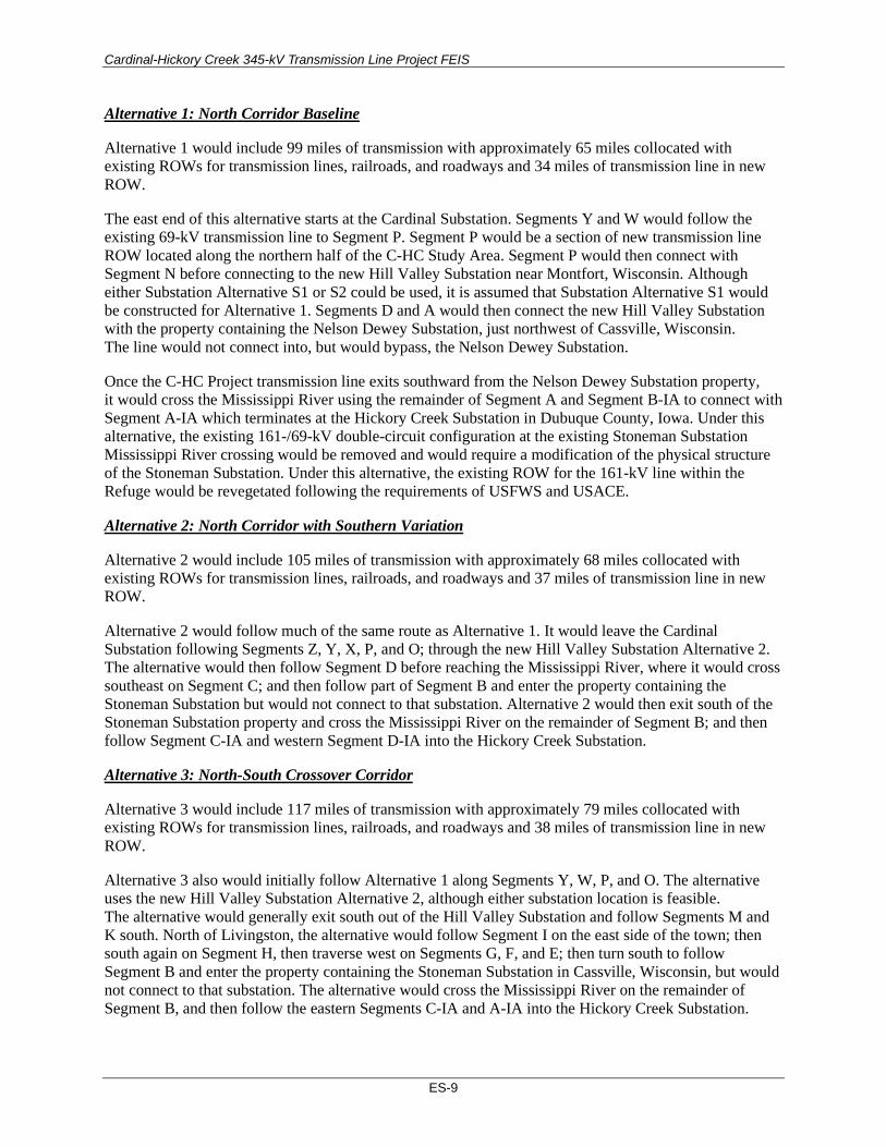
Alternative 1: North Corridor Baseline
Alternative 1 would include 99 miles of transmission with approximately 65 miles collocated with existing ROWs for transmission lines, railroads, and roadways and 34 miles of transmission line in new ROW.
The east end of this alternative starts at the Cardinal Substation. Segments Y and W would follow the existing 69-kV transmission line to Segment P. Segment P would be a section of new transmission line ROW located along the northern half of the C-HC Study Area. Segment P would then connect with Segment N before connecting to the new Hill Valley Substation near Montfort, Wisconsin. Although either Substation Alternative S1 or S2 could be used, it is assumed that Substation Alternative S1 would be constructed for Alternative 1. Segments D and A would then connect the new Hill Valley Substation with the property containing the Nelson Dewey Substation, just northwest of Cassville, Wisconsin. The line would not connect into, but would bypass, the Nelson Dewey Substation.
Once the C-HC Project transmission line exits southward from the Nelson Dewey Substation property, it would cross the Mississippi River using the remainder of Segment A and Segment B-IA to connect with Segment A-IA which terminates at the Hickory Creek Substation in Dubuque County, Iowa. Under this alternative, the existing 161-/69-kV double-circuit configuration at the existing Stoneman Substation Mississippi River crossing would be removed and would require a modification of the physical structure of the Stoneman Substation. Under this alternative, the existing ROW for the 161-kV line within the Refuge would be revegetated following the requirements of USFWS and USACE.
Alternative 2: North Corridor with Southern Variation
Alternative 2 would include 105 miles of transmission with approximately 68 miles collocated with existing ROWs for transmission lines, railroads, and roadways and 37 miles of transmission line in new ROW.
Alternative 2 would follow much of the same route as Alternative 1. It would leave the Cardinal Substation following Segments Z, Y, X, P, and O; through the new Hill Valley Substation Alternative 2. The alternative would then follow Segment D before reaching the Mississippi River, where it would cross southeast on Segment C; and then follow part of Segment B and enter the property containing the Stoneman Substation but would not connect to that substation. Alternative 2 would then exit south of the Stoneman Substation property and cross the Mississippi River on the remainder of Segment B; and then follow Segment C-IA and western Segment D-IA into the Hickory Creek Substation.
Alternative 3: North-South Crossover Corridor
Alternative 3 would include 117 miles of transmission with approximately 79 miles collocated with existing ROWs for transmission lines, railroads, and roadways and 38 miles of transmission line in new ROW.
Alternative 3 also would initially follow Alternative 1 along Segments Y, W, P, and O. The alternative uses the new Hill Valley Substation Alternative 2, although either substation location is feasible. The alternative would generally exit south out of the Hill Valley Substation and follow Segments M and K south. North of Livingston, the alternative would follow Segment I on the east side of the town; then south again on Segment H, then traverse west on Segments G, F, and E; then turn south to follow Segment B and enter the property containing the Stoneman Substation in Cassville, Wisconsin, but would not connect to that substation. The alternative would cross the Mississippi River on the remainder of Segment B, and then follow the eastern Segments C-IA and A-IA into the Hickory Creek Substation.

Cardinal-Hickory Creek 345-kV Transmission Line Project FEIS
ES-10
Alternative 4: South Baseline Corridor
Alternative 4 would include 119 miles of transmission with approximately 109 miles collocated with existing ROWs for transmission lines, railroads, and roadways and 10 miles of transmission line in new ROW.
Alternative 4 would leave the Cardinal Substation and traverse westerly on Segments Y and W. Just south of Cross Plains it would generally traverse south along Segments V and T until it passes just east of Mount Horeb. Alternative 4 would then follow U.S. Route 18 along Segment S, until it reaches and then passes on the north side of Dodgeville and traverses west on Segments Q and N; then follows Segment O south into the new Hill Valley Substation Alternative 2.
After leaving the substation, the transmission line would go south on Segments M and K; then just north of Livingston it would follow Segment I on the east side of the town; then south again on Segment H, then traverse west on Segments G, F, and E; then turn south to follow Segment B and to the Stoneman Substation; cross the Mississippi River on the remainder of Segment B, and then follow the eastern Segments C-IA and A-IA into the Hickory Creek Substation.
Alternative 5: South Alternative Corridor
Alternative 5 would include 128 miles of transmission with approximately 117 miles collocated with existing ROWs for transmission lines, railroads, and roadways and 10 miles of transmission line in new ROW.
Alternative 5 would follow much of the same route as Alternative 4, with a few adjustments. It would initially leave the Cardinal Substation and traverse westerly on Segments Y and W. Just south of Cross Plains it would generally traverse south along Segments V and U until it passed just west of Klevenville. The alternative would then pass just south of Mount Horeb, heading southwest along U.S. Route 18 and along Segment S, then would diverge just east of Dodgeville and follow Segment R south of Dodgeville. The alternative would turn west again, traversing north on Segment L to enter the new Hill Valley Substation Alternative 1.
After leaving the substation, the transmission line would go south on Segments L and K, then just north of Livingston it would follow Segment J to go around the west side of the town; then south again on Segment H, then would traverse west on Segments G, F, E, and C; then would turn south to the Nelson Dewey Substation. The transmission line would not connect into, but would bypass, the Nelson Dewey Substation. After leaving the Nelson Dewey Substation property, the alternative would turn south on Segment A, and then would follow Segment B-IA and the western Segment D-IA into the Hickory Creek Substation. Under this alternative, the existing 161-/69-kV double-circuit configuration at the existing Stoneman Substation Mississippi River crossing would be removed and would require a modification of the physical structure of the Stoneman Substation. Under this alternative, the existing ROW for the 161-kV line within the Refuge would be revegetated following the requirements of USFWS and USACE.
Alternative 6: South-North Crossover Corridor
Alternative 6 would include 101 miles of transmission with approximately 97 miles collocated with existing ROWs for transmission lines, railroads, and roadways and 4 miles of transmission line in new ROW. Minor adjustments were made to Alternative 6 between the DEIS and FEIS for consistency with the C-HC Project route in Wisconsin ordered by the PSCW on September 26, 2019. Adjustments include:
• Exchange of Segment X in place of Segment W and part of Segment V near the intersection of Stagecoach Road and County Road P south of Cross Plains, Wisconsin.
Cardinal-Hickory Creek 345-kV Transmission Line Project FEIS
ES-11
• Potential combined use of Segments S10B, S10C, S11B, and S11C along U.S. Highway 151 west of Barneveld, Wisconsin, to allow for ongoing discussions between the Utilities and the Wisconsin Department of Transportation.
• Accommodation of routing on either the north or south side of Wisconsin State Road 80 for approximately 1.5 miles along Segment Q02 east of Montfort, Wisconsin.
Alternative 6 would initially follow the southernmost route from the Cardinal Substation, using Segments Z, Y, and X. Just south of Cross Plains it would generally traverse south along Segments V and T until it passes just east of Mount Horeb. The alternative then turns southwest along U.S. Route 18 and along Segment S, until it reaches and then passes on the north side of Dodgeville and traverses west on Segments Q and N into the new Hill Valley Substation Alternative 1.
Once leaving the Hill Valley Substation, the route would cross into the southern portion of the Alternative 1 route. It would follow a portion of Segment L before then following Segments D and A to the Nelson Dewey Substation property, just northwest of Cassville, Wisconsin. The transmission line would not connect into, but would bypass, the Nelson Dewey Substation. Once the transmission line exits southward from the Nelson Dewey Substation property, it would cross the Mississippi River using the remainder of Segment A and Segment B-IA, and generally traverse south on Segment A-IA to terminate at the Hickory Creek Substation in Clayton County, Iowa. Under this alternative, the existing 161-/69-kV double-circuit configuration at the existing Stoneman Substation Mississippi River crossing would be removed, which would also result in a modification of the physical structure of the Stoneman Substation. Under this alternative, the existing ROW for the 161-kV line within the Refuge would be revegetated following the requirements of USFWS and USACE.
Alternatives within the Refuge
All action alternatives would cross the Refuge. There are three different options for crossing the Refuge that were carried forward for detailed analysis. Alternatives B-IA1 and B-IA2 are associated with the Nelson Dewey Mississippi River crossing, while Alternative C-IA is associated with the Stoneman Mississippi River crossing. The ROW width for all alternatives within the Refuge would be 260 feet, to accommodate the low-profile H-frame structures. The USFWS does not have a preferred alternative for crossing the Refuge, however, all segments that would cross the Refuge were developed in coordination with the USFWS, with the goal of reducing habitat fragmentation and resource impacts within the Refuge. The USFWS has received an application from the Utilities for a ROW permit. The route proposed in the ROW permit application has been evaluated through a Refuge compatibility determination (Appendix J) which is available for public comment with the same comment deadline as this FEIS.
Project Components The major components of the C-HC Project include transmission line facilities, substations, and communication systems. Typical design characteristics for the major project components are listed in Table ES-4. Final design characteristics would be determined in the detailed design phase of the project.

Cardinal-Hickory Creek 345-kV Transmission Line Project FEIS
ES-12
Table ES-4. Typical Transmission Line Components
Transmission Line Facility Description
Transmission line structures Monopole steel structures Low-profile H-frame tubular steel (Refuge) Lighting would only be installed on structures if required by Federal Aviation Administration (FAA) permit.
Typical structure height 90–175 feet for monopole structures 75 feet for low-profile H-frame structures (Refuge)
Typical span length 500–1,200 feet for monopole structures 500–600 feet for low-profile H-frame (Refuge)
Number of structures per mile 4–11 per mile
Directly embedded structures Temporary ground disturbance Permanent ground disturbance
See Section 2.4.1.3.1 for details. 100 × 100–foot workspace (0.23 acre); 20 to 30 feet deep 6 feet in diameter per structure (0.001 acre)
Reinforced concrete caissons Temporary ground disturbance Permanent ground disturbance
See Section 2.4.1.3.1 for details. 100 × 100–foot workspace (0.23 acre); 20 to 60 feet deep Up to 12 feet in diameter per structure (0.003 acre)
Voltage 345,000 volts or 345 kV
Circuit configuration Varies depending on location. Options include: 345-kV single circuit 345/69-kV double circuit 345/138-kV double circuit 345/161-kV double circuit 345/345-kV double circuit across Mississippi River but operated at 345/161-kV
Conductor size and type Outside of Mississippi River crossing: Diameter: 1.404 inches Type: Bundled T2 477 Hawk Mississippi River crossing: Diameter: 1.814 inches Type: Bundled T2-795 Drake
Design ground clearance of conductor 27 feet
Multiple existing substations along the proposed C-HC Project routes would be improved under any of the six action alternatives. In addition, one new substation, named the Hill Valley Substation, would be constructed near Montfort, Wisconsin.
Two types of structure foundations would be primarily used for the C-HC Project: directly embedded structures and reinforced concrete caissons. Directly embedded structures tend to be more economical than concrete foundations and are typically used for tangent and small-angle structures. Soil conditions would determine the appropriate foundation type and the required dimensions of the drilled holes. Where poor soils conditions exist, deeper and wider excavations would be necessary. In some places, access would be limited or protection of natural resources would be paramount (or both), making alternative construction methods prudent for consideration. Alternative foundations that might be needed to construct the C-HC Project include micro-piles, helical piers, vibratory piles, and vibratory caissons.
Wherever possible, the C-HC Project ROW would be accessed from existing public roads that intersect the ROW. Where public roads do not intersect the ROW, existing farm lanes, driveways, and cleared forest roads or trails would be used for access, along with existing waterway crossings such as bridges or

Cardinal-Hickory Creek 345-kV Transmission Line Project FEIS
ES-13
culverts. Before construction begins on the C-HC Project transmission line, some of these existing access roads might need modifications and improvements to allow for safe equipment movement to and from the C-HC Project ROW.
Affected Environment and Environmental Consequences NEPA requires agencies to assess the direct, indirect, and cumulative impacts of the alternatives carried forward for detailed analysis. Potential impacts were identified and evaluated for each aspect of the natural and built environments potentially affected by the C-HC Project, including the following resources: geology and soils; vegetation, including wetlands and special status plants; wildlife, including special status species; water resources and quality; air quality; noise; transportation; cultural and historic resources; land use, including agriculture and recreation; visual quality and aesthetics; socioeconomics and environmental justice; public health and safety; and the Upper Mississippi River National Wildlife and Fish Refuge. Direct and indirect impacts are discussed for each resource immediately following the characterization of each resource’s affected environment in Chapter 3 of the FEIS. Impact analysis for each resource also assumes successful implementation of the environmental commitments and best management practices (BMPs) that the Utilities would follow (Table ES-5). Table E-6 presents a summary comparison of potential impacts to resources analyzed in the FEIS for each action alternative.
Table ES-5. Environmental Commitments Common to All Action Alternatives
Resource Environmental Commitment
General • Regulatory agencies may require independent third-party environmental monitors related to permitted aspects of the C-HC Project. The Utilities use trained staff members or contractors as monitors for special resource conditions as a standard practice
Geology and Soils • An erosion control plan, coordinated with the Iowa Department of Natural Resources (IDNR) and Wisconsin Department of Natural Resources (WDNR), would be prepared once a route is approved, and BMPs would be employed near aquatic features (wetlands, streams, waterbodies) to minimize the potential for erosion and to prevent any sediments from entering the aquatic features.
• Erosion controls would be regularly inspected and maintained throughout the construction phase of a project until exposed soil has been adequately stabilized.
Vegetation, including Wetlands and Special Status Plants
General Vegetation • During restoration, erosion and sediment control measures, including measures for stabilization of
disturbed areas during and at the completion of construction, would be implemented as defined in the Stormwater Pollution Prevention Plan (SWPPP) developed for the C-HC Project. Areas where ground disturbance occurs would be monitored until 70% revegetation has been established.
• In non-agricultural areas where ground disturbance occurs, the area would be monitored until ground cover is reestablished to at least 70% of the vegetation type, density, and distribution that was documented in the area prior to construction.
• In areas that were previously forested, disturbed areas would be revegetated consistent with non-invasive herbaceous vegetation that occurs in the area.
Algific Talus Slopes • Upon final route selection and after landowner permission is obtained, additional habitat assessments
and algific talus slope surveys will be completed along the final route selected in Iowa. • Geotechnical surveys at the proposed pole locations will be completed along the final route selected in
Iowa to determine whether caves or cavities exist in bedrock that could be connected to algific talus slopes within or adjacent to the action area.
• Should any algific talus slopes be identified during habitat assessments, or any caves or cavities be detected in the bedrock during geotechnical surveys, they will be avoided by construction.
• Pole locations and construction access roads will be adjusted to avoid algific talus slopes, if present. • If algific talus slopes are identified, vegetation removal on steep slopes would be minimized to only the
amount necessary to maintain conductor clearances. • Broadcast spraying of herbicides will be avoided and careful spot spraying will be used in suitable
algific talus slope habitat areas.

Cardinal-Hickory Creek 345-kV Transmission Line Project FEIS
ES-14
Resource Environmental Commitment
Woodlands • To minimize the spread of oak wilt, the cutting or pruning of oak trees between April 15 and July 1 for
maintenance would be conducted in accordance with Wisconsin Administrative Code (WAC) Public Service Commission (PSC) 113.051.
• In Iowa, oak trees may be removed during maintenance activities but pruning oak trees would only occur during dormant periods.
• Practices that minimize the spread of emerald ash borer would be employed, which include avoiding movement of ash wood products (logs, posts, pulpwood, bark and bark products, and slash and chipped wood from tree clearing) and hardwood firewood from emerald ash borer quarantine areas to nonquarantine areas (see, for example, WAC Agriculture, Trade, and Consumer Protection [ATCP] 21.17). Where ash wood products cannot be left on-site, alternative plans would be developed to meet the requirements.
• Standard practices used in the quarantine area to avoid the spread of gypsy moth damage include inspections by trained staff and avoiding movement of wood products (logs, posts, pulpwood, bark and bark products, firewood, and slash and chipped wood from tree clearing) from gypsy moth quarantine areas to nonquarantine areas, according to WAC ATCP 21.10.
Wetlands • Impacts to wetlands would be minimized by one or more of the following measures:
o Conducting construction activities when wetland soils and water are frozen or stable and vegetation is dormant.
o Use of equipment with low ground-pressure tires or tracks. o Placement of construction matting to help minimize soil and vegetation disturbances and
distribute axle loads over a larger surface area, thereby reducing the bearing pressure on wetland soils.
• Access roads through wetlands will not require permanent fill. • Erosion control BMPs will be installed where needed to prevent soil erosion into and within wetlands. • Any spoils will be removed from wetlands to non-sensitive upland areas or other approved location.
Cleaning of construction equipment and mats, per the Wisconsin Council on Forestry’s “Invasive Species Best Management Practices: Rights-of-Way” guidance to mitigate the spread of invasive species (Appendix D). Where necessary to ameliorate minor impacts, such as rutting and vegetation disturbance due to equipment operation and mat placement in wetlands, site restoration activities will be implemented, monitored, and remedial measures applied until established restoration goals are achieved, as required by regulatory permits obtained for the C-HC Project.
Invasive Species • The Utilities would follow the Wisconsin Council on Forestry’s “Invasive Species Best Management
Practices: Rights-of-Way” guidance to mitigate the spread of invasive species (see Appendix D). • Work below the ordinary high-water mark (OHWM) of waterways would be avoided to the extent
practicable; the most likely activity would be withdrawing water to stabilize excavations. • Before moving construction equipment and material between waterway construction locations where
equipment or materials are placed below the OHWM of a waterway, standard inspection and disinfection procedures would be incorporated into construction methods as applicable (see WAC NR 329.04(5)).
• All natural areas, such as wetlands, forests, and prairies, will be surveyed for invasive species following construction and site revegetation. If new infestations of invasive species due to construction of the C-HC Project are discovered, measures should be taken to control the infestation. o The WDNR or IDNR, as applicable, would be consulted to determine the best methods for control
of encountered invasive species. • The Utilities will employ a Certified Pesticide Applicator for all herbicide applications within the C-HC
Project. The Certified Pesticide Applicators will only use herbicides registered and labeled by the USEPA and will follow all herbicide product label requirements. Herbicides approved for use in wetland and aquatic environments will be used in accordance with label requirements, as conditions warrant.
Wildlife, including Special Status Species
• In accordance with WDNR avoidance and minimization measures, reptile exclusion fencing would be installed in areas during the appropriate season where habitat is likely to support rare turtles, snakes, or salamanders.
• The Utilities will develop a project-specific Avian Protection Plan for the C-HC Project. An eagle management plan will be included as part of the Avian Protection Plan.
Cardinal-Hickory Creek 345-kV Transmission Line Project FEIS
ES-15
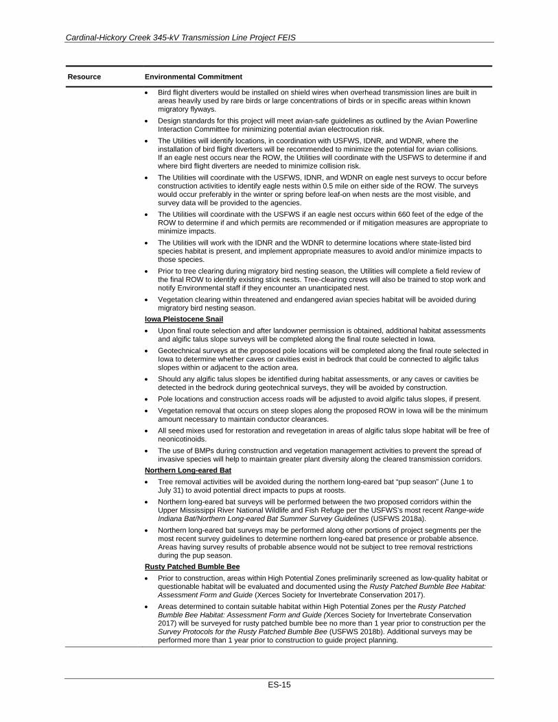
Resource Environmental Commitment
• Bird flight diverters would be installed on shield wires when overhead transmission lines are built in areas heavily used by rare birds or large concentrations of birds or in specific areas within known migratory flyways.
• Design standards for this project will meet avian-safe guidelines as outlined by the Avian Powerline Interaction Committee for minimizing potential avian electrocution risk.
• The Utilities will identify locations, in coordination with USFWS, IDNR, and WDNR, where the installation of bird flight diverters will be recommended to minimize the potential for avian collisions. If an eagle nest occurs near the ROW, the Utilities will coordinate with the USFWS to determine if and where bird flight diverters are needed to minimize collision risk.
• The Utilities will coordinate with the USFWS, IDNR, and WDNR on eagle nest surveys to occur before construction activities to identify eagle nests within 0.5 mile on either side of the ROW. The surveys would occur preferably in the winter or spring before leaf-on when nests are the most visible, and survey data will be provided to the agencies.
• The Utilities will coordinate with the USFWS if an eagle nest occurs within 660 feet of the edge of the ROW to determine if and which permits are recommended or if mitigation measures are appropriate to minimize impacts.
• The Utilities will work with the IDNR and the WDNR to determine locations where state-listed bird species habitat is present, and implement appropriate measures to avoid and/or minimize impacts to those species.
• Prior to tree clearing during migratory bird nesting season, the Utilities will complete a field review of the final ROW to identify existing stick nests. Tree-clearing crews will also be trained to stop work and notify Environmental staff if they encounter an unanticipated nest.
• Vegetation clearing within threatened and endangered avian species habitat will be avoided during migratory bird nesting season.
Iowa Pleistocene Snail • Upon final route selection and after landowner permission is obtained, additional habitat assessments
and algific talus slope surveys will be completed along the final route selected in Iowa. • Geotechnical surveys at the proposed pole locations will be completed along the final route selected in
Iowa to determine whether caves or cavities exist in bedrock that could be connected to algific talus slopes within or adjacent to the action area.
• Should any algific talus slopes be identified during habitat assessments, or any caves or cavities be detected in the bedrock during geotechnical surveys, they will be avoided by construction.
• Pole locations and construction access roads will be adjusted to avoid algific talus slopes, if present. • Vegetation removal that occurs on steep slopes along the proposed ROW in Iowa will be the minimum
amount necessary to maintain conductor clearances. • All seed mixes used for restoration and revegetation in areas of algific talus slope habitat will be free of
neonicotinoids. • The use of BMPs during construction and vegetation management activities to prevent the spread of
invasive species will help to maintain greater plant diversity along the cleared transmission corridors. Northern Long-eared Bat • Tree removal activities will be avoided during the northern long-eared bat “pup season” (June 1 to
July 31) to avoid potential direct impacts to pups at roosts. • Northern long-eared bat surveys will be performed between the two proposed corridors within the
Upper Mississippi River National Wildlife and Fish Refuge per the USFWS’s most recent Range-wide Indiana Bat/Northern Long-eared Bat Summer Survey Guidelines (USFWS 2018a).
• Northern long-eared bat surveys may be performed along other portions of project segments per the most recent survey guidelines to determine northern long-eared bat presence or probable absence. Areas having survey results of probable absence would not be subject to tree removal restrictions during the pup season.
Rusty Patched Bumble Bee • Prior to construction, areas within High Potential Zones preliminarily screened as low-quality habitat or
questionable habitat will be evaluated and documented using the Rusty Patched Bumble Bee Habitat: Assessment Form and Guide (Xerces Society for Invertebrate Conservation 2017).
• Areas determined to contain suitable habitat within High Potential Zones per the Rusty Patched Bumble Bee Habitat: Assessment Form and Guide (Xerces Society for Invertebrate Conservation 2017) will be surveyed for rusty patched bumble bee no more than 1 year prior to construction per the Survey Protocols for the Rusty Patched Bumble Bee (USFWS 2018b). Additional surveys may be performed more than 1 year prior to construction to guide project planning.

Cardinal-Hickory Creek 345-kV Transmission Line Project FEIS
ES-16
Resource Environmental Commitment
• Where the rusty patched bumble bee is confirmed to be present, disturbance and vegetation clearing within suitable habitats will be minimized to the extent possible.
• Seed mixes containing a diversity of native flowering plants will be used to reseed existing suitable habitat areas that require revegetation/restoration within High Potential Zones, as well as opportunity areas for expanding suitable habitat within known High Potential Zones.
• The use of BMPs during construction and vegetation management activities to prevent the spread of invasive species will help to maintain greater plant diversity along the cleared transmission corridors.
• Herbicide application where used for vegetation management purposes in suitable habitat within High Potential Zones will be targeted to limit the effects of the herbicide beyond the targeted species.
• To avoid or minimize impacts in areas documented by surveys to be occupied by rusty patched bumble bee, activities within occupied habitat will be sequenced with seasonal time frames as much as is feasible (i.e., late spring/summer work in woodlands to avoid overwintering queens, late fall/winter work in open areas to avoid foraging and nesting sites).
• USFWS believes the following reasonable and prudent measures are necessary and appropriate to minimize take of the rusty patched bumble bee: o Minimize pre-construction vegetation clearing and ground disturbance. o Use native species in restoration activities. o Maintain suitable habitat within the permanent ROW. o Document and report to the USFWS the timing and extent of disturbances within suitable habitat
for rusty patched bumble bee to help inform future consultations. • To implement the reasonable and prudent measures listed above, the Utilities must comply with the
following terms and conditions: o Minimize clearing, grading, and vegetation removal within suitable habitat areas in the High
Potential Zones. o Reseed all construction ROW suitable habitat areas (temporary and permanent) within the High
Potential Zones with pollinator-friendly native seed mixes consistent with recommendations provided by the USFWS. When possible, include species preferred by the rusty patched bumble bee and ensure that some plants are in bloom through the season when the rusty patched bumble bee may be present. The USFWS provides a list of plants favored by the species (USFWS 2019b).
o Provide a written summary of the suitable habitat impacted, the timing of impact as it pertains to the rusty patched bumble bee active and inactive seasons, and the estimated percentage of disturbed ground at completion of transmission line construction and other associated activities.
Water Resources and Water Quality
• An erosion control plan, coordinated with the IDNR and WDNR, will be prepared once a route is ordered/approved, and BMPs would be employed near aquatic features (wetlands, streams, waterbodies) to minimize the potential for erosion and to prevent any sediments from entering the aquatic features.
• Erosion controls would be regularly inspected and maintained throughout the construction phase of a project until exposed soil has been adequately stabilized.
• Waterway crossings would require a temporary clear span bridge (TCSB) to avoid the necessity of driving construction equipment through streams. Each TCSB would consist of construction mats, steel I-beam frames, or other similar material placed above the OHWM on either side to span the stream bank. If there are waterways that are too wide to clear span, a temporary bridge with in-stream support would be designed and constructed.
• The use of TCSBs would be minimized where possible by accessing the ROW from either side of the stream or by using existing public crossings to the extent practical. The Utilities would work with private landowners to identify alternative access routes to further reduce the use of stream crossings, if possible.
• For those streams that would not be crossed by construction vehicles and where stream-crossing permits have not been acquired, wire would be pulled across those waterways by boat, by helicopter, or by a person traversing across the waterway. Wire stringing activity may require that waterways be temporarily closed to navigation.
• No structures would be located below the OHWM. • Any dewatering within the project area during construction would be discharged to a non-sensitive
upland site to facilitate re-infiltration to the aquifer. • Nearby waterways could be used as a water source during project construction. The Utilities would
attempt to avoid water withdrawals during spawning seasons. The Utilities would coordinate water withdrawals with the IDNR and WDNR.
Cardinal-Hickory Creek 345-kV Transmission Line Project FEIS
ES-17
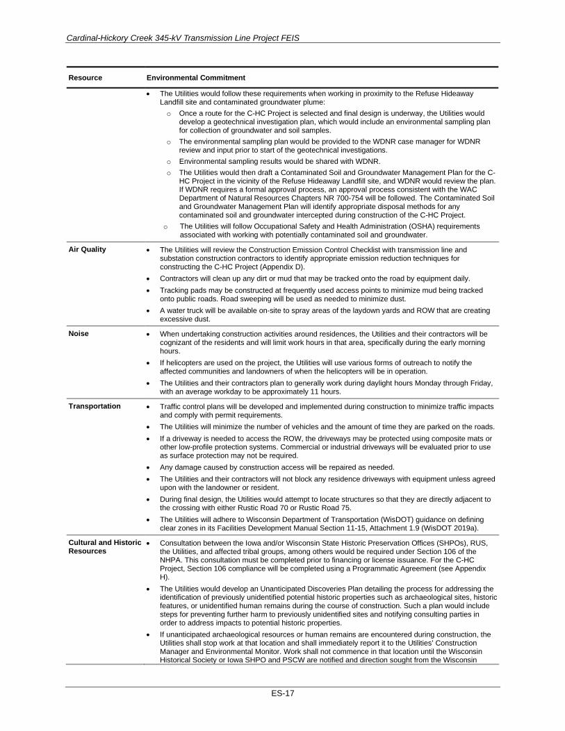
Resource Environmental Commitment
• The Utilities would follow these requirements when working in proximity to the Refuse Hideaway Landfill site and contaminated groundwater plume:
o Once a route for the C-HC Project is selected and final design is underway, the Utilities would develop a geotechnical investigation plan, which would include an environmental sampling plan for collection of groundwater and soil samples.
o The environmental sampling plan would be provided to the WDNR case manager for WDNR review and input prior to start of the geotechnical investigations.
o Environmental sampling results would be shared with WDNR. o The Utilities would then draft a Contaminated Soil and Groundwater Management Plan for the C-
HC Project in the vicinity of the Refuse Hideaway Landfill site, and WDNR would review the plan. If WDNR requires a formal approval process, an approval process consistent with the WAC Department of Natural Resources Chapters NR 700-754 will be followed. The Contaminated Soil and Groundwater Management Plan will identify appropriate disposal methods for any contaminated soil and groundwater intercepted during construction of the C-HC Project.
o The Utilities will follow Occupational Safety and Health Administration (OSHA) requirements associated with working with potentially contaminated soil and groundwater.
Air Quality • The Utilities will review the Construction Emission Control Checklist with transmission line and substation construction contractors to identify appropriate emission reduction techniques for constructing the C-HC Project (Appendix D).
• Contractors will clean up any dirt or mud that may be tracked onto the road by equipment daily. • Tracking pads may be constructed at frequently used access points to minimize mud being tracked
onto public roads. Road sweeping will be used as needed to minimize dust. • A water truck will be available on-site to spray areas of the laydown yards and ROW that are creating
excessive dust.
Noise • When undertaking construction activities around residences, the Utilities and their contractors will be cognizant of the residents and will limit work hours in that area, specifically during the early morning hours.
• If helicopters are used on the project, the Utilities will use various forms of outreach to notify the affected communities and landowners of when the helicopters will be in operation.
• The Utilities and their contractors plan to generally work during daylight hours Monday through Friday, with an average workday to be approximately 11 hours.
Transportation • Traffic control plans will be developed and implemented during construction to minimize traffic impacts and comply with permit requirements.
• The Utilities will minimize the number of vehicles and the amount of time they are parked on the roads. • If a driveway is needed to access the ROW, the driveways may be protected using composite mats or
other low-profile protection systems. Commercial or industrial driveways will be evaluated prior to use as surface protection may not be required.
• Any damage caused by construction access will be repaired as needed. • The Utilities and their contractors will not block any residence driveways with equipment unless agreed
upon with the landowner or resident. • During final design, the Utilities would attempt to locate structures so that they are directly adjacent to
the crossing with either Rustic Road 70 or Rustic Road 75. • The Utilities will adhere to Wisconsin Department of Transportation (WisDOT) guidance on defining
clear zones in its Facilities Development Manual Section 11-15, Attachment 1.9 (WisDOT 2019a).
Cultural and Historic Resources
• Consultation between the Iowa and/or Wisconsin State Historic Preservation Offices (SHPOs), RUS, the Utilities, and affected tribal groups, among others would be required under Section 106 of the NHPA. This consultation must be completed prior to financing or license issuance. For the C-HC Project, Section 106 compliance will be completed using a Programmatic Agreement (see Appendix H).
• The Utilities would develop an Unanticipated Discoveries Plan detailing the process for addressing the identification of previously unidentified potential historic properties such as archaeological sites, historic features, or unidentified human remains during the course of construction. Such a plan would include steps for preventing further harm to previously unidentified sites and notifying consulting parties in order to address impacts to potential historic properties.
• If unanticipated archaeological resources or human remains are encountered during construction, the Utilities shall stop work at that location and shall immediately report it to the Utilities’ Construction Manager and Environmental Monitor. Work shall not commence in that location until the Wisconsin Historical Society or Iowa SHPO and PSCW are notified and direction sought from the Wisconsin

Cardinal-Hickory Creek 345-kV Transmission Line Project FEIS
ES-18
Resource Environmental Commitment
Historical Society or Iowa SHPO. Interested tribes would also be notified during this time. Construction may resume after the direction is followed and the qualified archaeologist’s reports, if any, are received and approved by the Wisconsin Historical Society or Iowa SHPO.
Land Use, including Agriculture and Recreation
• Where possible, siting in agricultural areas would be along fence lines or between fields or along public road ROW so that the proposed structures would be located along the edge of the land area used for agricultural purposes. If conflicts occur, landowners would be consulted during the real estate acquisition process to accommodate landowner needs to the extent practicable.
• During the final design process, landowner input would be obtained to place structures such that impacts to drain tiles would be minimized to the extent practicable.
• During construction, matting may be used to more evenly distribute the weight of heavy equipment, and low ground-pressure construction equipment may also be used.
• After construction, damaged drain tiles would be repaired to preconstruction conditions. • Where appropriate, minimization techniques, such as topsoil replacement and deep tilling, may be
used. • Construction vehicles may be cleaned before entering the organic farm parcels, in accordance with
input from the landowner. • During the easement negotiation, landowners can decline the use of herbicides for vegetation
management activities once the line is in operation. Therefore, no herbicide would be applied within portions of the ROW on which the landowner wishes not to introduce it.
• If construction activity occurs during wet conditions and soils are rutted, the ruts will be repaired as soon as conditions allow, to reduce the potential for impacts.
• To minimize soil compaction during construction in agricultural lands, low-lying areas, saturated soils, or sensitive soils, low-impact machinery with wide tracks could be used.
• Prior to and during construction, the Utilities will coordinate with land managers regarding public notification about construction activities and temporary closures of public areas.
• See more detailed BMPs for agricultural lands in Appendix D.
Visual Quality and Aesthetics
• Steel monopoles with a weathered finish will be used at visually sensitive locations to minimize the visual impacts to the landscape.
Socioeconomics and Environmental Justice
• Short-term impacts to agricultural lands would be mitigated by providing compensation to producers and by restoring agricultural lands to the extent practicable.
Public Health and Safety
• If the proposed transmission lines parallel or cross distribution lines, appropriate measures can be taken to address any induced voltages.
Upper Mississippi River National Wildlife and Fish Refuge
• For the portion of the C-HC Project within the Refuge, preliminary low-profile structures are proposed with a design height to match the existing tree cover within the Refuge (approximately 75 feet) to reduce the potential of avian collisions.
• The structures would be horizontal-symmetrical H-frame structures on concrete foundations with a typical span length of approximately 500 feet and would consist primarily of tubular steel H-frame structures.
• All conductors on these low-profile structures would be placed on one horizontal plane and the shield wire would be marked with avian flight diverters.
• Construction on the Refuge would need to occur outside the eagle nesting season (typically January 15 to June 15) or outside a 660-foot exclusion zone to avoid disturbance to nesting adult, chick, and fledgling eagles.
• For the alternatives that cross the Mississippi River at the Nelson Dewey Substation (alternatives 1, 5, and 6), additional minimization steps are proposed: o The Utilities propose to mitigate adverse impacts to forest resources in the Refuge through
restoration and enhancement of forest resources both within and off Refuge lands. A restoration plan would be developed in consultation with the USFWS and USACE. The restoration plan would supplement existing USFWS efforts to restore bottomland hardwood forest within the Refuge, specifically on the floodplain of the Turkey River. Mitigation may also include the reestablishment and/or expansion of mature woodlands near the Nelson Dewey Substation and/or other non-Refuge locations adjacent to Refuge lands. These restoration efforts would mitigate adverse impacts on public lands.
• Revegetation within the Refuge would be conducted in concert with USFWS and USACE review and direction and in compliance with applicable North American Electric Reliability Corporation (NERC)-regulated vegetation standards. As with the design of the project, the Utilities would work closely with

Cardinal-Hickory Creek 345-kV Transmission Line Project FEIS
ES-19
Resource Environmental Commitment
the USACE and USFWS to identify the location, type, and overall revegetation plan that would be appropriate for the project and this specific location of the Refuge.
• In addition to the environmental commitments outlined above and other mitigation to be developed with the USFWS and USACE, as part of the USACE and USFWS permit application processes, the Utilities would develop a project-specific mitigation plan. This plan would need to be deemed acceptable by USACE and USFWS prior to the issuance of permits. Appendix I contains the preliminary Federal mitigation plan for the C-HC Project.

Cardinal-Hickory Creek 345-kV Transmission Line Project FEIS
ES-20
Table ES-6. Comparison Summary for Action Alternatives (MiT = minor temporary; MoT = moderate temporary; MiP = minor permanent; MoP = moderate permanent; MaP = major permanent)
Resource Group Alternative 1 Alternative 2 Alternative 3 Alternative 4 Alternative 5 Alternative 6
Geology and Soils
MoT and MoP impacts to 149 acres of shallow soils; 93 acres of wet soils; 173 acres of steep slope soils; and severe erosion potential for 1,265 acres; MiP impacts to 63,000 cubic yards of displaced subsurface soils and ≤24 acres of sensitive soils
MoT and MoP impacts to 141 acres of shallow soils; 104 acres of wet soils; 171 acres of steep slope soils; and severe erosion potential for 1,352 acres; MiP impacts to 66,000 cubic yards of displaced subsurface soils and ≤24 acres of sensitive soils
MoT and MoP impacts to 159 acres of shallow soils; 106 acres of wet soils; 171 acres of steep slope soils; and severe erosion potential for 1,284 acres; MiP impacts to 73,000 cubic yards of displaced subsurface soils and ≤24 acres of sensitive soils
MoT and MoP impacts to 155 acres of shallow soils; 81 acres of wet soils; 96 acres of steep slope soils; and severe erosion potential for 1,111 acres; MiP impacts to 80,000 cubic yards of displaced subsurface soils and ≤24 acres of sensitive soils
MoT and MoP impacts to 165 acres of shallow soils; 91 acres of wet soils; 92 acres of steep slope soils; and severe erosion potential for 1,238 acres; MiP impacts to 85,000 cubic yards of displaced subsurface soils and ≤24 acres of sensitive soils
MoT and MoP impacts to 144 acres of shallow soils; 73 acres of wet soils; 82 acres of steep slope soils; and severe erosion potential for 1,092 acres; MiP impacts to 70,000 cubic yards of displaced subsurface soils and ≤24 acres of sensitive soils
Vegetation MoT and MoP impacts to 228 acres of grassland, 524 acres of forest, and 10 acres of shrubland
MoT and MoP impacts to 249 acres of grassland, 530 acres of forest, and 9 acres of shrubland
MoT and MoP impacts to 302 acres of grassland, 504 acres of forest, and 10 acres of shrubland
MoT and MoP impacts to 433 acres of grassland, 236 acres of forest, and 16 acres of shrubland
MoT and MoP impacts to 454 acres of grassland, 245 acres of forest, and 8 acres of shrubland
MoT and MoP impacts to 352 acres of grassland, 250 acres of forest, and 17 acres of shrubland
Wetlands MoT impacts to 72 acres; MoP impacts to 38 acres
MoT impacts to 69 acres; MoP impacts to 52 acres
MoT impacts to 58 acres; MoP impacts to 49 acres
MoT impacts to 54 acres; MoP impacts 16 acres
MoT impacts to 61 acres; MoP impacts 5 acres
MoT impacts to 63 acres; MoP impacts 7 acres
Special Status Plants
Minor impacts Same impact as Alternative 1
Same impact as Alternative 1
Same impact as Alternative 1
Same impact as Alternative 1
Same impact as Alternative 1
Wildlife MiT impacts to 228 acres of grassland habitat, 110 acres of wetlands, and 15 acres of open water; MoP impacts to 524 acres of forest habitat
MiT impacts to 249 acres of grassland habitat, 121 acres of wetlands, and 13 acres of open water; MoP impacts to 530 acres of forest habitat
MiT impacts to 302 acres of grassland habitat, 107 acres of wetlands, and 11 acres of open water; MoP impacts to 504 acres of forest habitat
MiT impacts to 433 acres of grassland habitat, 69 acres of wetlands, and 11 acres of open water; MoP impacts to 236 acres of forest habitat
MiT impacts to 454 acres of grassland habitat, 66 acres of wetlands, and 10 acres of open water; MoP impacts to 245 acres of forest habitat
MiT impacts to 352 acres of grassland habitat, 76 acres of wetlands, and 14 acres of open water; MoP impacts to 250 acres of forest habitat
Special Status Species
May affect, not likely to adversely affect the Iowa Pleistocene snail; MoT impacts to 140 acres of high-potential and 1,096 acres low-potential rusty patched bumble bee habitat
Same impact as Alternative 1 to Iowa Pleistocene snail; MoT impacts to 141 acres of high-potential and 1,109 acres low-potential rusty patched bumble bee habitat
Same impact as Alternative 1 to Iowa Pleistocene snail; MoT impacts to 141 acres of high-potential and 1,157 acres low-potential rusty patched bumble bee habitat
Same impact as Alternative 1 to Iowa Pleistocene snail; MoT impacts to 93 acres of high-potential and 1,183 acres low-potential rusty patched bumble bee habitat
Same impact as Alternative 1 to Iowa Pleistocene snail; MoT impacts to 73 acres of high-potential and 822 acres low-potential rusty patched bumble bee habitat
Same impact as Alternative 1 to Iowa Pleistocene snail; MoT impacts to 87 acres of high-potential and 814 acres low-potential rusty patched bumble bee habitat
Water Resources
MiT and MiP impacts to 8 impaired waterways, 3 outstanding and exceptional waters, and 11 trout streams
MiT and MiP impacts to 8 impaired waterways, 4 outstanding and exceptional waters, and 15 trout streams
MiT and MiP impacts to 5 impaired waterways, 5 outstanding and exceptional waters, and 10 trout streams
MiT and MiP impacts to 8 impaired waterways, 8 outstanding and exceptional waters, and 7 trout streams
MiT and MiP impacts to 9 impaired waterways, 8 outstanding and exceptional waters, and 8 trout streams
MiT and MiP impacts to 6 impaired waterways, 7 outstanding and exceptional waters, and 12 trout streams

Cardinal-Hickory Creek 345-kV Transmission Line Project FEIS
ES-21
Resource Group Alternative 1 Alternative 2 Alternative 3 Alternative 4 Alternative 5 Alternative 6
Floodplains MiT impacts to 14 crossings > 1,000 feet, 43,661 linear feet of floodplains, and 9,901 linear feet of floodway
MiT impacts to 14 crossings > 1,000 feet, 40,100 linear feet of floodplains, and 8,620 linear feet of floodway
MiT impacts to 10 crossings > 1,000 feet, 28,310 linear feet of floodplains, and 8,620 linear feet of floodway
MiT impacts to 8 crossings > 1,000 feet, 21,150 linear feet of floodplains, and 8,620 linear feet of floodway
MiT impacts to 7 crossings > 1,000 feet, 21,051 linear feet of floodplains, and 8,9,091 linear feet of floodway
MiT impacts to 11 crossings > 1,000 feet, 35,091 linear feet of floodplains, and 9,091 linear feet of floodway
Air Quality MiT impacts Same impact as Alternative 1
Same impact as Alternative 1
Same impact as Alternative 1
Same impact as Alternative 1
Same impact as Alternative 1
Noise MiT impacts to 2 sensitive noise receptors
MiT impacts to 3 sensitive noise receptors
MiT impacts to 4 sensitive noise receptors
MiT impacts to 10 sensitive noise receptors
MiT impacts to 2 sensitive noise receptors
MiT impacts to 8 sensitive noise receptors
Transportation MiT impacts to 2,381 roadway segments; MoT impacts to 1 major river and 24 railroad segments; MoP impacts to 5 airport/heliport facilities
MiT impacts to 2,408 roadway segments; MoT impacts to 1 major river and 24 railroad segments; MoP impacts to 5 airport/heliport facilities
MiT impacts to 2,658 roadway segments; MoT impacts to 1 major river and 30 railroad segments; MoP impacts to 6 airport/heliport facilities
MiT impacts to 3,024 roadway segments; MoT impacts to 1 major river and 26 railroad segments; MoP impacts to 9 airport/heliport facilities
MiT impacts to 3,070 roadway segments; MoT impacts to 1 major river and 26 railroad segments; MoP impacts to 10 airport/heliport facilities
MiT impacts to 2,765 roadway segments; MoT impacts to 1 major river and 20 railroad segments; MoP impacts to 8 airport/heliport facilities
Cultural and Historic Resources
12 National Register of Historic Places (NRHP)-listed, determined eligible, or assumed eligible resources could be impacted
14 NRHP-listed, determined eligible, or assumed eligible resources could be impacted
18 NRHP-listed, determined eligible, or assumed eligible resources could be impacted
24 NRHP-listed, determined eligible, or assumed eligible resources could be impacted
31 NRHP-listed, determined eligible, or assumed eligible resources could be impacted
14 NRHP-listed, determined eligible, or assumed eligible resources could be impacted
Land Use See impacts to land cover classes under Vegetation
See impacts to land cover classes under Vegetation
See impacts to land cover classes under Vegetation
See impacts to land cover classes under Vegetation
See impacts to land cover classes under Vegetation
See impacts to land cover classes under Vegetation
Agriculture MiT impacts to 1,096 acres of agriculture land cover type, 399 acres of prime farmland, and 553 acres of farmland of statewide importance; MaP impacts to 11 acres of prime farmland and 11 acres of farmland of statewide importance
MiT impacts to 1,146 acres of agriculture land cover type, 375 acres of prime farmland, and 630 acres of farmland of statewide importance; MaP impacts to 22 acres of prime farmland
MiT impacts to 1,299 acres of agriculture land cover type, 636 acres of prime farmland, and 661 acres of farmland of statewide importance; MaP impacts to 22 acres of prime farmland
MiT impacts to 1,361 acres of agriculture land cover type, 872 acres of prime farmland, and 725 acres of farmland of statewide importance; MaP impacts to 22 acres of prime farmland
MiT impacts to 1,534 acres of agriculture land cover type, 935 acres of prime farmland, and 815 acres of farmland of statewide importance; MaP impacts to 11 acres of prime farmland and 11 acres of farmland of statewide importance
MiT impacts to 1,164 acres of agriculture land cover type, 644 acres of prime farmland, and 610 acres of farmland of statewide importance; MaP impacts to 11 acres of prime farmland and 11 acres of farmland of statewide importance
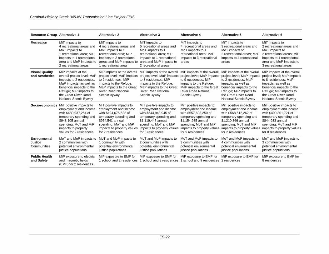
Cardinal-Hickory Creek 345-kV Transmission Line Project FEIS
ES-22
Resource Group Alternative 1 Alternative 2 Alternative 3 Alternative 4 Alternative 5 Alternative 6
Recreation MiT impacts to 4 recreational areas and MoT impacts to 1 recreational area; MiP impacts to 1 recreational area and MoP impacts to 2 recreational areas
MiT impacts to 4 recreational areas and MoT impacts to 1 recreational area; MiP impacts to 2 recreational areas and MoP impacts to 1 recreational area
MiT impacts to 5 recreational areas and MoT impacts to 1 recreational area; MiP impacts to 1 recreational area and MoP impacts to 2 recreational areas
MiT impacts to 4 recreational areas and MoT impacts to 1 recreational area; MoP impacts to 3 recreational areas
MiT impacts to 3 recreational areas and MoT impacts to 2 recreational areas; MoP impacts to 4 recreational areas
MiT impacts to 2 recreational areas and MoT impacts to 2 recreational areas; MiP impacts to 1 recreational area and MoP impacts to 3 recreational areas
Visual Quality and Aesthetics
MiP impacts at the overall project level; MaP impacts to 2 residences; MaP impacts, as well as beneficial impacts to the Refuge; MiP impacts to the Great River Road National Scenic Byway
MiP impacts at the overall project level; MaP impacts to 2 residences; MiP impacts to the Refuge; MaP impacts to the Great River Road National Scenic Byway
MiP impacts at the overall project level; MaP impacts to 3 residences; MiP impacts to the Refuge; MaP impacts to the Great River Road National Scenic Byway
MiP impacts at the overall project level; MaP impacts to 9 residences; MiP impacts to the Refuge; MaP impacts to the Great River Road National Scenic Byway
MiP impacts at the overall project level; MaP impacts to 2 residences; MaP impacts, as well as beneficial impacts to the Refuge; MiP impacts to the Great River Road National Scenic Byway
MiP impacts at the overall project level; MaP impacts to 8 residences; MaP impacts, as well as beneficial impacts to the Refuge; MiP impacts to the Great River Road National Scenic Byway
Socioeconomics MiT positive impacts to employment and income with $480,937,254 of temporary spending and $948,105 annual spending; MoT and MiP impacts to property values for 2 residences
MiT positive impacts to employment and income with $494,675,522 of temporary spending and $954,541 annual spending; MoT and MiP impacts to property values for 2 residences
MiT positive impacts to employment and income with $544,948,945 of temporary spending and $1,119,447 annual spending; MoT and MiP impacts to property values for 3 residences
MiT positive impacts to employment and income with $557,603,250 of temporary spending and $1,154,985 annual spending; MoT and MiP impacts to property values for 9 residences
MiT positive impacts to employment and income with $568,612,262 of temporary spending and $1,210,366 annual spending; MoT and MiP impacts to property values for 2 residences
MiT positive impacts to employment and income with $490,301,721 of temporary spending and $844,933 annual spending; MoT and MiP impacts to property values for 8 residences
Environmental Justice Communities
MoT and MoP impacts to 2 communities with potential environmental justice populations
MoT and MoP impacts to 1 community with potential environmental justice populations
MoT and MoP impacts to 2 communities with potential environmental justice populations
MoT and MoP impacts to 3 communities with potential environmental justice populations
MoT and MoP impacts to 4 communities with potential environmental justice populations
MoT and MoP impacts to 3 communities with potential environmental justice populations
Public Health and Safety
MiP exposure to electric and magnetic fields (EMF) for 2 residences
MiP exposure to EMF for 1 school and 2 residences
MiP exposure to EMF for 1 school and 3 residences
MiP exposure to EMF for 1 school and 9 residences
MiP exposure to EMF for 2 residences
MiP exposure to EMF for 8 residences

Cardinal-Hickory Creek 345-kV Transmission Line Project FEIS
ES-23
Resource Group Alternative 1 Alternative 2 Alternative 3 Alternative 4 Alternative 5 Alternative 6
The Refuge Segment B-IA1 39 acres of ROW within the Refuge; Permanent impacts to 23 acres of the Turkey River restoration area, 0.1 acre of wetlands, and 0 acres of forest removal within ROW; Restoration of 14 acres of the existing 161-kV transmission line ROW
46 acres of ROW within the Refuge; Permanent impacts to 0 acres in the Turkey River restoration area, 12 acres of forested wetlands and 46 acres of non-forested wetland within ROW
Same impact as Alternative 2
Same impact as Alternative 2
Same impact as Alternative 1
Same impact as Alternative 1
Segment B-IA2 44 acres of ROW within the Refuge; Permanent impacts 27 acres in the Turkey River restoration area, 1 acre of wetlands, and 1 acre of forest removal within ROW; Restoration of 14 acres of the existing 161-kV transmission line ROW

Cardinal-Hickory Creek 345-kV Transmission Line Project FEIS
E-24
Cumulative Impacts Cumulative impacts are defined as “the impact on the environment which results from the incremental impact of the action when added to other past, present, and reasonably foreseeable future actions regardless of what agency (federal or nonfederal) or person undertake such other actions” (40 CFR 1508.7).
The cumulative impact analysis describes the types of present and reasonably future actions that are included in the cumulative impact analysis area for each affected resource identified and evaluated in the FEIS. For the C-HC Project, the following types of projects were identified for the cumulative action scenario: urban development projects, large restoration projects, recreation improvements, renewable energy generation, other electric transmission projects, major transportation improvements, and pipelines.
Cardinal-Hickory Creek 345-kV Transmission Line Project FEIS
i
CONTENTS Executive Summary ..................................................................................................................................... i Acronyms and Abbreviations ..................................................................................................................... i Chapter 1. Project Purpose and Need .................................................................................................. 1
1.1 Introduction ............................................................................................................................... 1 1.2 Project Background ................................................................................................................... 4
1.2.1 Description of Proposed Project ...................................................................................... 4 1.2.2 Description of Utilities .................................................................................................... 5
1.3 Electric System Reliability and Planning .................................................................................. 6 1.3.1 Federal Energy Regulatory Commission ......................................................................... 7 1.3.2 North American Electric Reliability Corporation ............................................................ 8 1.3.3 The Utilities’ Participation in the Planning and Implementation of the MVPs ............. 11
1.4 Project Purpose and Need ........................................................................................................ 11 1.4.1 Increase Transfer Capability Enabling Additional Generation ...................................... 14 1.4.2 Reduce the Overall Cost of Delivered Electricity ......................................................... 17 1.4.3 Address Reliability Issues on the Regional Bulk Transmission System ....................... 18 1.4.4 Avoided Infrastructure Costs and Other Grid Improvements ........................................ 19
1.5 Purpose of and Need for Federal Action ................................................................................. 19 1.5.1 Rural Utilities Service ................................................................................................... 19 1.5.2 U.S. Fish and Wildlife Service ...................................................................................... 20 1.5.3 U.S. Army Corps of Engineers ...................................................................................... 21
1.6 Required Federal and State Agency Approvals ....................................................................... 22 1.6.1 Federal and State Permits and Approvals Summary ..................................................... 22 1.6.2 Certificate of Public Convenience and Necessity in Wisconsin .................................... 24 1.6.3 Electric Transmission Franchise in Iowa ....................................................................... 25
1.7 Public Participation for Federal Decisions .............................................................................. 26 1.7.1 Public Notification Efforts ............................................................................................. 27 1.7.2 Public Scoping Meetings ............................................................................................... 27 1.7.3 Scoping Comments Received ........................................................................................ 28 1.7.4 DEIS Public Comment Period ....................................................................................... 29 1.7.5 DEIS Public Comments Received ................................................................................. 30
Chapter 2. PROPOSED PROJECT AND ALTERNATIVES ......................................................... 33 2.1 Development of Alternatives ................................................................................................... 33 2.2 Alternatives Considered but Not Evaluated in Detail ............................................................. 36
2.2.1 Alternative Transmission Line Corridors ...................................................................... 36 2.2.2 Non-Transmission, Lower-Voltage, and Underground Alternatives ............................. 58
2.3 Description of Alternatives ..................................................................................................... 67 2.3.1 No Action Alternative ................................................................................................... 67 2.3.2 Alternative Transmission Line Routes .......................................................................... 67
2.4 Description of the Proposed Project ........................................................................................ 92 2.4.1 Project Components ....................................................................................................... 92 2.4.2 Preconstruction Activities ............................................................................................ 104 2.4.3 Construction Activities ................................................................................................ 109 2.4.4 Operation and Maintenance Activities ........................................................................ 115 2.4.5 Retirement of the N-9 Transmission Line and Construction of a New 69-kV Tap ..... 117 2.4.6 Decommissioning ........................................................................................................ 120

Cardinal-Hickory Creek 345-kV Transmission Line Project FEIS
ii
2.5 Comparison of Alternatives ................................................................................................... 121 2.6 Agency Preferred Alternative ................................................................................................ 126 2.7 Environmentally Preferable Alternative ................................................................................ 127
APPENDICES
Appendix A Detailed Electricity Characteristics Appendix B List of Tribes Contacted Appendix C Alternatives Development Process Appendix D Best Management Practices Appendix E Special Status Plants List Appendix F Draft Environmental Impact Statement Public Comment Report Appendix G U.S. Fish and Wildlife Service Biological Opinion Appendix H Programmatic Agreement Appendix I Federal Mitigation Plan Appendix J U.S. Fish and Wildlife Service Compatibility Determination for the Upper Mississippi
River National Wildlife and Fish Refuge
FIGURES Figure 1.1-1. Proposed Cardinal-Hickory Creek 345-kV Transmission Line Project. ................................. 3 Figure 1.3-1. FERC regional transmission organizations. ............................................................................ 7 Figure 1.3-2. MVP portfolio map. .............................................................................................................. 10 Figure 1.4-1. Transmission backbone system in the vicinity of the C-HC Project. .................................... 13 Figure 2.2-1. Alternative Corridors 1 transmission line corridor not considered in detail. ........................ 39 Figure 2.2-2. Alternative Corridors 2 transmission line corridor not considered in detail. ........................ 40 Figure 2.2-3. Alternative Corridors 3 transmission line corridor not considered in detail. ........................ 41 Figure 2.2-4. Alternative Corridors 4 transmission line corridor not considered in detail. ........................ 42 Figure 2.2-5. Alternative Corridors 5 transmission line corridor not considered in detail. ........................ 43 Figure 2.2-6. Alternative Corridors 6 transmission line corridor not considered in detail. ........................ 46 Figure 2.2-7. Alternative Corridors 7 transmission line corridor not considered in detail. ........................ 47 Figure 2.2-8. Alternative Corridors 8 transmission line corridor not considered in detail. ........................ 48 Figure 2.2-9. Alternative Corridors 9 transmission line corridor not considered in detail. ........................ 49 Figure 2.2-10. Alternative Corridors 10 transmission line corridor not considered in detail. .................... 50 Figure 2.2-11. Alternative Corridors 11 transmission line corridor not considered in detail. .................... 51 Figure 2.2-12. Alternative Corridors 12 transmission line corridor not considered in detail. .................... 52 Figure 2.2-13. Alternative Mississippi River crossings not considered in detail. (Source: Burns and
McDonnell 2016) ..................................................................................................................... 54 Figure 2.2-14. Refuge segments dismissed from detailed analysis. ........................................................... 57 Figure 2.3-1. Transmission line alternative corridor segments map. .......................................................... 70 Figure 2.3-2. Alternative 1 transmission line corridor map. ....................................................................... 72 Figure 2.3-3. Alternative 1 Hill Valley Substation map. ............................................................................ 73 Figure 2.3-4. Alternative 2 transmission line corridor map. ....................................................................... 75 Figure 2.3-5. Alternative 2 Hill Valley Substation map. ............................................................................ 76 Figure 2.3-6. Alternative 3 transmission line corridor map. ....................................................................... 78
Cardinal-Hickory Creek 345-kV Transmission Line Project FEIS
iii
Figure 2.3-7. Alternative 3 Hill Valley Substation map. ............................................................................ 79 Figure 2.3-8. Alternative 4 transmission line corridor map. ....................................................................... 81 Figure 2.3-9. Alternative 4 Hill Valley Substation map. ............................................................................ 82 Figure 2.3-10. Alternative 5 transmission line corridor map. ..................................................................... 84 Figure 2.3-11. Alternative 5 Hill Valley Substation map. .......................................................................... 85 Figure 2.3-12. Alternative 6 transmission line corridor map. ..................................................................... 87 Figure 2.3-13. Alternative 6 Hill Valley Substation map. .......................................................................... 88 Figure 2.3-14. C-HC Project options for crossing the Refuge. ................................................................... 91 Figure 2.4-1. Preliminary grading plan for the Hill Valley Substation. ...................................................... 96 Figure 2.4-2. Typical 345-kV single-circuit monopole structure. .............................................................. 98 Figure 2.4-3. Typical 345-/69-kV double-circuit monopole structure. ....................................................... 98 Figure 2.4-4. Typical 345-/138-kV up to 345-/ 345-kV double-circuit monopole structure. ..................... 99 Figure 2.4-5. Low-profile 345-/345-kV double-circuit structure for the Refuge crossing. ........................ 99 Figure 2.4-6. Low-profile 345-/345-kV double-circuit structure for the Mississippi River crossing. ...... 100 Figure 2.4-7. Mats in wet meadow. .......................................................................................................... 106 Figure 2.4-8. Timber mats being placed in wooded wetland. ................................................................... 107 Figure 2.4-9. Timber-mat equipment bridge at a stream crossing. ........................................................... 107 Figure 2.4-10. Foundation excavation using an auger in dry upland soils. ............................................... 110 Figure 2.4-11. Structure location in a wetland—matted work platform, foundation, spoil pile (to be
removed), and erosion control. .............................................................................................. 110 Figure 2.4-12. Installing the top section of a structure with a crane. ........................................................ 112 Figure 2.4-13. Installing a structure on a foundation with a helicopter. ................................................... 112 Figure 2.4-14. Pulling the conductor through the structure arms.............................................................. 113 Figure 2.4-15. N-9 transmission line overview map. ................................................................................ 118 Figure 2.4-16. New connection between N-9 transmission line and Turkey River Substation. ............... 119

Cardinal-Hickory Creek 345-kV Transmission Line Project FEIS
iv
TABLES
Table 1.3-1. MVP Portfolio Summary ........................................................................................................ 10 Table 1.4-1. MISO Generation Interconnection Agreements Conditional on the C-HC Project Being
in Service ................................................................................................................................. 14 Table 1.4-2. Generation Interconnection Requests in Southwestern and South-Central Wisconsin .......... 16 Table 1.4-3. Transmission Projects Eliminated as a Result of the Cardinal-Hickory Creek Project .......... 19 Table 1.6-1. Federal and State Permits or Approvals for the C-HC Project ............................................... 23 Table 1.7-1. First Public Scoping Meeting Dates, Times, and Locations ................................................... 27 Table 1.7-2. Federal Entities and Federally Recognized Tribes that Submitted Comments ...................... 28 Table 1.7-3. State and Local Entities that Submitted Comments ............................................................... 28 Table 1.7-4. Non-Governmental Organizations that Submitted Comments ............................................... 28 Table 1.7-5. Summary of Public Scoping Comments Received, by Topic ................................................. 29 Table 1.7-6. DEIS Public Comment Meeting Dates, Times, and Locations ............................................... 30 Table 1.7-7. Summary of DEIS Comments Received, by Topic ................................................................ 31 Table 2.2-1. Alternative Transmission Line Corridors Not Carried Forward for Detailed Analysis—
Wisconsin ................................................................................................................................. 36 Table 2.2-2. Alternative Transmission Line Corridors Not Carried Forward for Detailed Analysis—
Mississippi River Crossing ...................................................................................................... 55 Table 2.2-3. Comparison of the Non-Transmission, Lower-Voltage, and Underground Transmission
Alternatives to the Need Described for the Proposed Action .................................................. 60 Table 2.3-1. Summary of C-HC Project Options for Crossing the Refuge ................................................. 90 Table 2.4-1. Typical Transmission Line Components ................................................................................ 92 Table 2.5-1. Comparison Summary for Action Alternatives .................................................................... 122

ACRONYMS AND ABBREVIATIONS °F degree(s) Fahrenheit µg/m3 micrograms per cubic meter ACA Alternative Crossings Analysis ACGIH American Conference of Governmental Industrial Hygienists ACHP Advisory Council on Historic Preservation ACSR aluminum conductors steel reinforced ADT average daily traffic AES Alternatives Evaluation Study ANSI American National Standards Institute APE area of potential effects APLIC Avian Powerline Interaction Committee ATC American Transmission Company LLC ATCP Agriculture, Trade, and Consumer Protection ATV all-terrain vehicle BA Biological Assessment BLS Bureau of Labor Statistics BMP best management practice BNSF Burlington Northern-Santa Fe BO Biological Opinion Burns and McDonnell
Burns and McDonnell Engineering Company
CapX2020 report CapX2020 345 kV Underground Report (Power Engineers, Inc. 2010) CEQ Council on Environmental Quality CERCLA Comprehensive Environmental Response, Compensation, and Liability Act CFR Code of Federal Regulations CH4 methane C-HC Project Cardinal-Hickory Creek Project CIAA cumulative impact analysis area CO carbon monoxide CO2 carbon dioxide Complex Ice Age Complex at Cross Plains CPCN certificate of public convenience and necessity CPRS Canadian Pacific Railway CRP Conservation Reserve Program CWA Clean Water Act

Cardinal-Hickory Creek 345-kV Transmission Line Project FEIS
ii
Dairyland Dairyland Power Cooperative DATCP Wisconsin Department of Agriculture, Trade, and Consumer Protection dB decibels dBA A-weighted decibels DEIS draft environmental impact statement DEM digital elevation model DOT Department of Transportation EA environmental assessment EC Engineering Circular EFHRAN European Health Risk Assessment Network on Electromagnetic Fields Exposure EIS environmental impact statement EMF electric and magnetic fields EO executive order ESA Endangered Species Act FAA Federal Aviation Administration FEIS final environmental impact statement FEMA Federal Emergency Management Act FERC Federal Energy Regulatory Commission FHWA Federal Highway Administration FIRM Flood Insurance Rate Map FPPA Farmland Protection Policy Act GHG greenhouse gas GIS geographic information system HAP hazardous air pollutant HUC Hydrologic Unit Code IA Iowa IAC Iowa Administrative Code IARC International Agency for Research on Cancer ICNIRP International Commission on Non-Ionizing Radiation Protection IDNR Iowa Department of Natural Resources IEEE Institute of Electrical and Electronics Engineers ILF in-lieu fee Iowa DOT Iowa Department of Transportation IPaC Information for Planning and Consultation ITC Midwest ITC Midwest LLC IUB Iowa Utilities Board KOP key observation point

Cardinal-Hickory Creek 345-kV Transmission Line Project FEIS
iii
kV kilovolt kV/m kilovolts per meter kWh kilowatt-hours Ldn day-night average noise level Leq energy average noise level Lmax the maximum sound level for the loudest piece of equipment MCS Macro-Corridor Study MFL Managed Forest Law mG milliGauss MISO Midcontinent Independent System Operator, Inc. MPS Multiple Property Submission MRO Midwest Reliability Organization MTEP MISO Transmission Expansion Plan MVAR mega volt ampere reactive MVP multi-value project MW megawatt(s) MWh megawatt hours N2O nitrous oxide NAAQS National Ambient Air Quality Standards NASS National Agricultural Statistics Service NEPA National Environmental Policy Act NERC North American Electric Reliability Corporation NESC National Electrical Safety Code NHI Natural Heritage Inventory NHPA National Historic Preservation Act NIEHS National Institute of Environmental Health Sciences NLCD National Land Cover Dataset NOA Notice of Availability NOAA National Oceanic and Atmospheric Administration NOI Notice of Intent NOX nitrogen oxides NPS National Park Service NR Natural Resources NRCS Natural Resources Conservation Service NRHP National Register of Historic Places NRPB National Radiological Protection Board NST National Scenic Trail
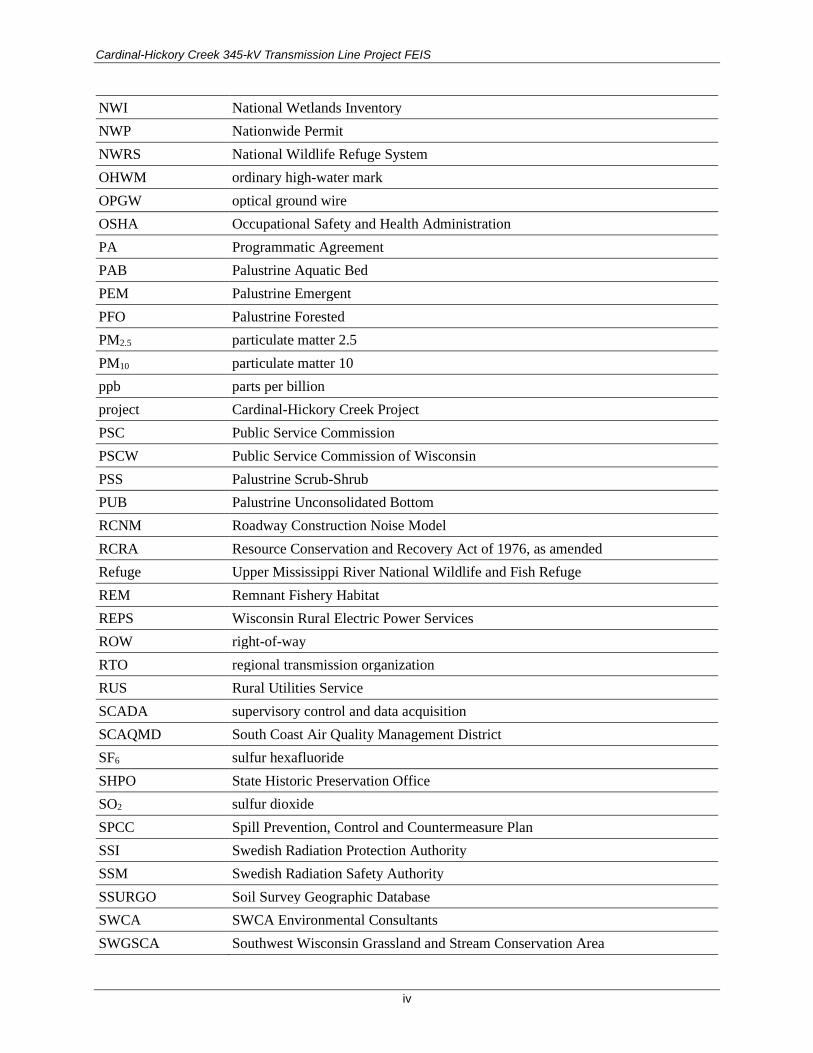
Cardinal-Hickory Creek 345-kV Transmission Line Project FEIS
iv
NWI National Wetlands Inventory NWP Nationwide Permit NWRS National Wildlife Refuge System OHWM ordinary high-water mark OPGW optical ground wire OSHA Occupational Safety and Health Administration PA Programmatic Agreement PAB Palustrine Aquatic Bed PEM Palustrine Emergent PFO Palustrine Forested PM2.5 particulate matter 2.5 PM10 particulate matter 10 ppb parts per billion project Cardinal-Hickory Creek Project PSC Public Service Commission PSCW Public Service Commission of Wisconsin PSS Palustrine Scrub-Shrub PUB Palustrine Unconsolidated Bottom RCNM Roadway Construction Noise Model RCRA Resource Conservation and Recovery Act of 1976, as amended Refuge Upper Mississippi River National Wildlife and Fish Refuge REM Remnant Fishery Habitat REPS Wisconsin Rural Electric Power Services ROW right-of-way RTO regional transmission organization RUS Rural Utilities Service SCADA supervisory control and data acquisition SCAQMD South Coast Air Quality Management District SF6 sulfur hexafluoride SHPO State Historic Preservation Office SO2 sulfur dioxide SPCC Spill Prevention, Control and Countermeasure Plan SSI Swedish Radiation Protection Authority SSM Swedish Radiation Safety Authority SSURGO Soil Survey Geographic Database SWCA SWCA Environmental Consultants SWGSCA Southwest Wisconsin Grassland and Stream Conservation Area

Cardinal-Hickory Creek 345-kV Transmission Line Project FEIS
v
SWPPP Stormwater Pollution Prevention Plan TCP Traditional Cultural Property TCSB temporary clear span bridge TMDL Total Maximum Daily Load TOSCA Toxic Substances Control Act UMRR Upper Mississippi River Restoration U.S. United States USACE U.S. Army Corps of Engineers U.S.C. United States Code USDA U.S. Department of Agriculture USDOT U.S. Department of Transportation USEPA U.S. Environmental Protection Agency USFWS U.S. Fish and Wildlife Service USGS U.S. Geological Survey the Utilities Dairyland Power Cooperative, American Transmission Company LLC, and ITC
Midwest LLC VOC volatile organic compound WAC Wisconsin Administrative Code WCEP Whooping Crane Eastern Partnership WDNR Wisconsin Department of Natural Resources WDNR NHI WDNR Natural Heritage Inventory WI Wisconsin WIS Wisconsin Highway WisDOT Wisconsin Department of Transportation WSOR Wisconsin and Southern Railroad WUS waters of the U.S. WWCT Wisconsin Wetland Conservation Trust

CHAPTER 1. PROJECT PURPOSE AND NEED
1.1 INTRODUCTION Dairyland Power Cooperative (Dairyland), American Transmission Company LLC (ATC), and ITC Midwest LLC (ITC Midwest), together referred to as “the Utilities,” propose to construct and own a new 345-kilovolt (kV) transmission line between Dane County, Wisconsin, and Dubuque County, Iowa. The proposed project would include approximately 100 to 125 miles of new transmission line; an upgrade and possibly relocation of an existing Mississippi River crossing to a 345-/345-kV double-circuit line; building a new substation near Montfort, Wisconsin; upgrades to the Cardinal, Stoneman, and the Hickory Creek Substations; constructing a new less than 1-mile-long 69-kV transmission line near the Mississippi River; and rebuilding the Turkey River Substation. These upgrades and new construction projects are all together referred to as the “Cardinal-Hickory Creek Project” (or the “C-HC Project”) (Figure 1.1-1). Due to the scope and potential impact of the C-HC Project and the involvement and actions of certain Federal agencies, an environmental impact statement (EIS) is being prepared to fulfill obligations specified under the National Environmental Policy Act (NEPA).
This EIS is organized as follows:
• Chapter 1 (Project Purpose and Need): Identifies the purpose of and need for the project, purpose of and need for the Federal agencies’ decisions, and information about public participation.
• Chapter 2 (Proposed Project and Alternatives): Presents a detail description of the alternatives analyzed in detail in this EIS, summarizes the alternatives dismissed from detailed analysis, and presents the agencies’ preferred alternative for the C-HC Project.
• Chapter 3 (Affected Environment and Environmental Consequences): Includes a resource-by-resource discussion of the affected environment, or existing conditions, for the resources present in the study area and the analysis of impacts to those resources from the C-HC Project.
• Chapter 4 (Cumulative Impacts and Other Required Considerations): Includes a resource-by-resource discussion of impacts from past, present, and reasonably foreseeable future projects that could contribute cumulatively to impacts from the C-HC Project.
• Chapter 5 (Coordination and Consultation): Presents a list of coordination and consultation activities conducted under NEPA and related laws for the C-HC Project to date.
• Chapter 6 (List of Preparers): Identification of individuals who substantively contributed to the development of this EIS.
• Chapter 7 (Literature Cited): A list of references used to write and support the analysis in this EIS.
• Chapter 8 (Distribution List): A list of repositories where this EIS was made available to the public.
• Chapter 9 (Glossary): The glossary of terms to provide the reader with additional information and background on terms and concepts discussed in this document.
• Appendix A (Detailed Electricity Characteristics): Provides a summary of regional load forecasts and Wisconsin and Iowa state population projections.

Cardinal-Hickory Creek 345-kV Transmission Line Project FEIS
2
• Appendix B (List of Tribes Contacted): A list of tribes contacted by the U.S. Department of Agriculture (USDA) Rural Utilities Service (RUS) for the C-HC Project and this EIS to date.
• Appendix C (Alternatives Development Process): Defines the transmission line subsegments that comprise each action alternative and summarizes the alternative evaluation process followed to ensure the action alternatives were reasonable and technically feasible.
• Appendix D (Best Management Practices): Presents an overview of the best management practices (BMPs) for the C-HC Project.
• Appendix E (Special Status Plants List): A list of special status plants in the C-HC Project study area.
• Appendix F (Draft EIS Public Comment Report): A summary of public comments received during the draft EIS (DEIS) public review period and responses to those comments from RUS.
• Appendix G (Biological Opinion): The Biological Opinion for the C-HC Project issued by the U.S. Fish and Wildlife Service (USFWS) to comply with the Endangered Species Act, Section 7.
• Appendix H (Programmatic Agreement): The Programmatic Agreement for the C-HC Project signed by consulting parties to comply with the National Historic Preservation Act, Section 106.
• Appendix I (Federal Mitigation Plan): The plan outlining all mitigation measures required by RUS, USFWS, and U.S. Army Corps of Engineers (USACE) associated with each agency’s action described in the final EIS (FEIS), Section 1.5.
• Appendix J (USFWS Compatibility Determination): The compatibility determination addresses whether the C-HC Project is a compatible use or is not a compatible use for the Upper Mississippi River National Wildlife and Fish Refuge (Refuge).
This chapter discusses the purpose of and need for the C-HC Project and the objectives of the FEIS. A further description of the project and its participants is included. The Utilities, which will be responsible for the construction and have ownership of the project, and the Federal agencies, state agencies, and regional transmission organization (RTO) responsible for regulating, providing planning oversight, and/or ensuring the efficient operation, stability, and reliability of the high-voltage transmission system affected by the project, are all described. The Federal agencies that will participate in preparing the FEIS, along with their regulatory framework and authorizing actions pertinent to the project, are described. Furthermore, this chapter provides a description of public participation activities held for the C-HC Project to date, and a summary of issues analyzed in this FEIS.
Dairyland intends to request financial assistance from RUS to fund its anticipated 9% ownership interest in the C-HC Project. Appendix A provides information regarding Dairyland’s system and load growth that are pertinent to its application for financial assistance. RUS administers programs that provide much-needed infrastructure or infrastructure improvements to rural communities. This includes the RUS Electric Program, which provides funding via loans or guaranteed loans to finance the construction or improvement of electric distribution, transmission, and generation facilities in rural areas of the United States. RUS’s evaluation to potentially finance the Dairyland portion of the C-HC Project constitutes a Federal action, requiring it to perform an environmental review within the context of NEPA. To comply with NEPA, RUS has prepared this FEIS prior to the determination of whether RUS funds should be obligated to finance Dairyland’s ownership portion of the project and prior to initiation of construction.

Cardinal-Hickory Creek 345-kV Transmission Line Project FEIS
3
Figure 1.1-1. Proposed Cardinal-Hickory Creek 345-kV Transmission Line Project.
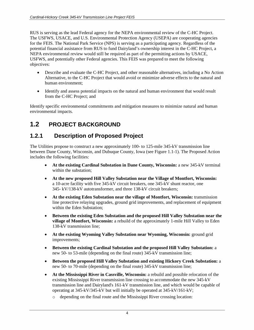
Cardinal-Hickory Creek 345-kV Transmission Line Project FEIS
4
RUS is serving as the lead Federal agency for the NEPA environmental review of the C-HC Project. The USFWS, USACE, and U.S. Environmental Protection Agency (USEPA) are cooperating agencies for the FEIS. The National Park Service (NPS) is serving as a participating agency. Regardless of the potential financial assistance from RUS to fund Dairyland’s ownership interest in the C-HC Project, a NEPA environmental review would still be required as part of the permitting actions by USACE, USFWS, and potentially other Federal agencies. This FEIS was prepared to meet the following objectives:
• Describe and evaluate the C-HC Project, and other reasonable alternatives, including a No Action Alternative, to the C-HC Project that would avoid or minimize adverse effects to the natural and human environment;
• Identify and assess potential impacts on the natural and human environment that would result from the C-HC Project; and
Identify specific environmental commitments and mitigation measures to minimize natural and human environmental impacts.
1.2 PROJECT BACKGROUND
1.2.1 Description of Proposed Project The Utilities propose to construct a new approximately 100- to 125-mile 345-kV transmission line between Dane County, Wisconsin, and Dubuque County, Iowa (see Figure 1.1-1). The Proposed Action includes the following facilities:
• At the existing Cardinal Substation in Dane County, Wisconsin: a new 345-kV terminal within the substation;
• At the new proposed Hill Valley Substation near the Village of Montfort, Wisconsin: a 10-acre facility with five 345-kV circuit breakers, one 345-kV shunt reactor, one 345- kV/138-kV autotransformer, and three 138-kV circuit breakers;
• At the existing Eden Substation near the village of Montfort, Wisconsin: transmission line protective relaying upgrades, ground grid improvements, and replacement of equipment within the Eden Substation;
• Between the existing Eden Substation and the proposed Hill Valley Substation near the village of Montfort, Wisconsin: a rebuild of the approximately 1-mile Hill Valley to Eden 138-kV transmission line;
• At the existing Wyoming Valley Substation near Wyoming, Wisconsin: ground grid improvements;
• Between the existing Cardinal Substation and the proposed Hill Valley Substation: a new 50- to 53-mile (depending on the final route) 345-kV transmission line;
• Between the proposed Hill Valley Substation and existing Hickory Creek Substation: a new 50- to 70-mile (depending on the final route) 345-kV transmission line;
• At the Mississippi River in Cassville, Wisconsin: a rebuild and possible relocation of the existing Mississippi River transmission line crossing to accommodate the new 345-kV transmission line and Dairyland's 161-kV transmission line, and which would be capable of operating at 345-kV/345-kV but will initially be operated at 345-kV/161-kV; o depending on the final route and the Mississippi River crossing location:

Cardinal-Hickory Creek 345-kV Transmission Line Project FEIS
5
• a new 161-kV terminal and transmission line protective relaying upgrades within the existing Nelson Dewey Substation in Cassville, Wisconsin;
• a replaced or reinforced structure within the Stoneman Substation in Cassville, Wisconsin;
• Multiple, partial, or complete rebuilds of existing 69-kV, 138-kV, and 161-kV transmission lines in Wisconsin that would be collocated with the new 345-kV line;
• At the existing Turkey River Substation in Clayton County, Iowa: one new 161-/69-kV transformer, three new 161-kV circuit breakers, and four new 69-kV circuit breakers; and
• At the existing Hickory Creek Substation in Dubuque County, Iowa: a new 345-kV terminal within the existing Hickory Creek Substation.
The estimated cost for the proposed C-HC Project is $500 million to $550 million (in 2023 dollars), depending on the alternative selected. If approved, construction of the project would begin in early 2020, and the in-service date would be scheduled for 2023.
1.2.2 Description of Utilities The Utilities that would construct and own the proposed C-HC Project are described below. Ownership of the various components of the C-HC Project would include the following:
• Dairyland would:
o own 9% of the C-HC Project 345-kV transmission line, o be the sole owner of the 161-kV transmission line from the Turkey River Substation
to either the Stoneman Substation or the Nelson Dewey Substation, depending on the final route, that will be rebuilt with the 345-kV Mississippi River crossing,
o be the sole owner of any equipment replaced in the Stoneman Substation, and o be the owner of some equipment within the Turkey River Substation.
• ATC already owns the Cardinal Substation, would own the new Hill Valley Substation, and would own 45.5% of the C-HC Project 345-kV transmission line.
• ITC Midwest already owns the Hickory Creek Substation, Turkey River Substation, and would own 45.5% of the C-HC Project 345-kV transmission line.
1.2.2.1 Dairyland Power Cooperative Dairyland is a not-for-profit generation and transmission cooperative headquartered in La Crosse, Wisconsin. Dairyland is owned by and provides the wholesale power requirements for 24 separate distribution cooperative members in southern Minnesota, western Wisconsin, northern Iowa, and northern Illinois, and 17 municipal utilities in Wisconsin, Minnesota, and Iowa. Dairyland serves a population of approximately 600,000 and owns approximately 3,200 miles of electric transmission lines. Dairyland receives power to meet the needs of its members through self-owned generation facilities and power it purchases from other entities.
Dairyland owns or has under contract four conventional fossil-fueled and 23 renewable electric generation facilities, currently operating or soon to be operating. Dairyland’s total rated generating capacity is over 1,280 megawatts (MW). Of that total, 1,007 MW are conventional fossil-fueled facilities and about 275 MW are renewable facilities. Dairyland’s renewable energy capacity includes four wind energy generation facilities with a capacity of 216 MW. Dairyland also purchases wholesale electricity

Cardinal-Hickory Creek 345-kV Transmission Line Project FEIS
6
from major solar installations located in Westby, Wisconsin; Oronoco, Minnesota; and Galena, Illinois (Dairyland 2016a).
Dairyland continues to add renewable generation and to support other renewable programs. They recently signed power purchase agreements for 15 solar generation projects in southwestern Wisconsin and northeastern Iowa, ranging from 0.5 to 2.5 MW each and totaling 20.3 MW of installed generating capacity. In addition to these commercial facilities, there are over 850 consumer-owned distributed generation solar installations in the Dairyland service area (Dairyland 2016a).
Dairyland promotes the education of its members and consumers regarding renewable energy. Dairyland has developed a Solar for Schools renewable energy and education initiative. This initiative not only includes installation of solar facilities on campuses, but also provides education and workforce training for the students. Under this program, solar installations were constructed at the Western Technical College – Independence Campus and three schools in Wisconsin (Alma Area School, Cochrane-Fountain City School, and De Soto Area Middle and High School) (Dairyland 2016a).
Dairyland has also developed an Evergreen Renewable Energy Program. Dairyland’s members distribute renewable electricity to their consumers, who voluntarily support renewable electricity development by paying $1.50 more each month for each block of 100 kilowatt hours (kWh) (i.e., 1.5 cents/kWh). These additional funds are then used to support development of new renewable electricity facilities and programs (Dairyland 2017).
1.2.2.2 American Transmission Company, LLC, and ITC Midwest LLC
ATC, through its corporate manager ATC Management, Inc. (collectively ATC), began operations in 2001 as the nation's first multistate, transmission-only utility. ATC owns and operates more than 9,500 miles of high-voltage transmission lines and 530 substations in portions of Wisconsin, Michigan, Minnesota, and Illinois. Since its formation, ATC has upgraded or built more than 2,300 miles of transmission lines and 175 substations. ATC is headquartered in Pewaukee, Wisconsin.
ITC Midwest is a wholly-owned subsidiary of ITC Holdings Corp., the nation’s largest independent electric transmission company. ITC Midwest is headquartered in Cedar Rapids, Iowa, and maintains operating facilities in Dubuque, Iowa City, and Perry, Iowa, as well as Albert Lea and Lakefield, Minnesota. ITC Midwest connects more than 700 communities with approximately 6,600 circuit miles of transmission lines in Iowa, southern Minnesota, northeastern Missouri, and northwestern Illinois. ITC Midwest has also received a Certificate of Authority to operate as a public utility in Wisconsin.
1.3 ELECTRIC SYSTEM RELIABILITY AND PLANNING The availability and reliability of electricity is a critical component to the economy, social system, and security of the United States. Creating and maintaining jobs in manufacturing and in the service industry depends on reliable electricity every day; and it provides essential power to the health care system, schools, military installations, homes, law enforcement agencies, and other emergency response agencies. Electricity is a highly perishable commodity and, except for the use of batteries on a small scale, it cannot be stored like water or gas; electricity must be generated as needed, and supply must be kept in balance with demand. Additionally, unlike water or gas, electricity follows the path of least resistance and cannot be easily routed in a specific direction. Therefore, given the scope, distances, and millions of people it serves, the generation and transmission of electricity requires enormous planning, cooperation, coordination, and continuous real-time monitoring and control on a 24-hour daily basis.

Cardinal-Hickory Creek 345-kV Transmission Line Project FEIS
7
Responsibility for electrical system planning, reliability, and transmission operational oversight within much of the United States, including Wisconsin and Iowa, is primarily dependent upon large regional transmission organizations (Figure 1.3-1). The oversight and actions of these RTOs result in the more efficient use of electrical energy resources and in a transmission system capable of delivering electricity with improved availability and reliability. Utilities, state governments, and other planning entities work with the RTOs, whose authority is mainly derived through national energy policy legislation.
Figure 1.3-1. FERC regional transmission organizations.
The roles of RTOs are shaped by the rules and policies of two agencies: Federal Energy Regulatory Commission (FERC) and the North American Electric Reliability Corporation (NERC). The roles and responsibilities of these organizations and the RTOs are briefly summarized below.
1.3.1 Federal Energy Regulatory Commission The FERC is an independent Federal commission within the U.S. Department of Energy that regulates the interstate transmission of electricity as well as natural gas and oil. FERC has the responsibility to protect the reliability of the high-voltage interstate transmission system, and it has the authority to develop and enforce reliability standards. These standards are in place to ensure system reliability, which is defined by the U.S. Department of Energy’s Energy Infrastructure Administration as “a measure of the ability of the system to continue operation while some lines or generators are out of service. Reliability deals with the performance of the system under stress” (U.S. Energy Information Administration 2017).
The Federal Power Act sets forth FERC’s obligations to plan for sufficient transmission to serve native load, including the “expansion of transmission facilities” (16 U.S.C. § 824q(b)(4)). FERC has implemented this authority through numerous orders including Orders 890, 1000, and 2000.

Cardinal-Hickory Creek 345-kV Transmission Line Project FEIS
8
Planning reforms under Order 1000 (FERC 2012) established three requirements for transmission planning:
1. Each public utility transmission provider must participate in a regional transmission planning process that satisfies the transmission planning principles of Order 890 and produces a regional transmission plan.
2. Local and regional transmission planning processes must consider transmission needs driven by public policy requirements established by state or Federal laws or regulations. Each public utility transmission provider must establish procedures to identify transmission needs driven by public policy requirements and evaluate proposed solutions to those transmission needs.
3. Public utility transmission providers in each pair of neighboring transmission planning regions must coordinate to determine if there are more efficient or cost-effective solutions to their mutual transmission needs
FERC Order 2000 (FERC 1999) identifies the seven minimum functions of an RTO as follows:
1. Administer its own tariff and employ a transmission pricing system that will promote efficient use and expansion of transmission and generation facilities;
2. Create market mechanisms to manage transmission congestion;
3. Develop and implement procedures to address parallel path flow issues;
4. Serve as a supplier of last resort for all ancillary services required in Order 888 and subsequent orders;
5. Operating a single Open Access Same-Time Information System site for transmission facilities under its control with responsibility for independently calculating Total Transmission Capacity and Available Transmission Capacity;
6. Monitor markets to identify design flaws and market power; and
7. Plan and coordinate necessary transmission additions and upgrades.
FERC established RTOs for the purposes of “promoting efficiency and reliability in the operation and planning of the electric transmission grid and ensuring non-discrimination in the provision of electric transmission services” (18 Code of Federal Regulations [CFR] 35.34(a)). RTOs are essentially responsible for the transmission systems within their areas. RTO responsibilities include pricing, reliability assurance, and determining when and how new generators can have access to the system. RTOs are also responsible for designing and administering a FERC-approved tariff, which is a published volume of rate schedules and general terms and conditions under which a product or service will be supplied (National Renewable Energy Laboratory 2017).
1.3.2 North American Electric Reliability Corporation In 2006, the NERC was given authority, under FERC regulations, to enforce the standards established in the Energy Policy Act of 2005.
NERC Reliability Standards (NERC 2017a) apply to all owners, users, and operators of the bulk power system, which includes the electric generation and transmission system in North America. Any state may

Cardinal-Hickory Creek 345-kV Transmission Line Project FEIS
9
take action to ensure the “safety, adequacy and reliability of electric service within that state, as long as such action is not inconsistent with any Reliability Standard” (16 United States Code [U.S.C.] 824o(i)(3)). Among the many reliability standards NERC has developed are sets of standards for transmission operations and transmission planning.
NERC works with eight regional entities to improve the reliability of the bulk power system. The members of the regional entities come from all segments of the electric industry: investor-owned utilities; Federal power agencies; rural electric cooperatives; state, municipal, and provincial utilities; independent power producers; power marketers; and end-use customers. These entities account for virtually all the electricity supplied in the United States, Canada, and a portion of Baja California Norte, Mexico. The Midwest Reliability Organization (MRO) is one of the eight regional entities (NERC 2017b).
The MRO’s primary function is to monitor and enforce the NERC Reliability Standards. The MRO has delegated much of its transmission reliability responsibility to two Reliability Coordinators: the MISO for the United States and SaskPower for Canada. The C-HC Project falls within the regions overseen by MRO and MISO.
1.3.2.1 Midcontinent Independent System Operator MISO is responsible for developing the procedures, processes, and practices for electric reliability within the MRO’s U.S. jurisdiction (MISO 2014). MISO is responsible for producing and maintaining an updated reliability plan—a document that describes how MISO meets the requirements of NERC Transmission Operating Standards (MISO 2014). Each year, MISO develops its annual MISO Transmission Expansion Planning (MTEP). For its planning process, MISO uses a “bottom-up, top-down approach,” which means MISO obtains data and plans from all of its transmission owners (bottom-up) and conducts its own transmission planning (top-down).
From 2008 to 2011, in conjunction with state utility regulators and industry stakeholders including the Utilities, MISO evaluated how to build transmission facilities that would meet the significant renewable energy requirements within MISO at the lowest delivered megawatt-hour (MWh) cost. While MISO considered stakeholder comments, ultimately the MISO Board of Directors approved the final projects. In 2011, as part of the 2011 MISO MTEP, MISO adopted a portfolio of 17 multi-value projects (MVPs) to provide economic, reliability, and public policy benefits across what was then the entire MISO footprint: all or portions of 13 states and one Canadian province. MISO ultimately designated the C-HC Project as part of the MVP portfolio to be developed, identified as MVP #5 in Figure 1.3-2 and Table 1.3-1. MISO confirmed the MVP’s benefits in the 2014 MTEP14 MVP Triennial Review (MISO 2014) and again in the 2017 MTEP17 MVP Triennial Review (MISO 2017a).

Cardinal-Hickory Creek 345-kV Transmission Line Project FEIS
10
Figure 1.3-2. MVP portfolio map.
Table 1.3-1. MVP Portfolio Summary
ID Project, Location Voltage (kV) ID Project, Location Voltage
(kV)
1 Big Stone-Brookings (SD) 345 10 Pawnee-Pana (IL) 345
2 Brookings, SD-SE Twin Cities (MN/SD) 345 11 Pana-Mt. Zion-Kansas-Sugar Creek (IL/IN) 345
3 Lakefield Jct.-Winnebago-Winco-Burt Area & Sheldon-Burt Area-Webster (MN/IA)
345 12 Reynolds-Burr Oak-Hiple (IN) 345
4 Winco-Lime Creek-Emery-Black Hawk-Hazleton (IA)
345 13 Michigan Thumb Loop Expansion (MI) 345
5* LaCrosse-N. Madison-Cardinal & Dubuque Co-Spring Green-Cardinal (WI)
345 14 Reynolds-Greentown (IN) 765
6 Ellendale-Big Stone (ND/SD) 345 15 Pleasant Prairie-Zion Energy Center (WI/IL) 345
7 Adair-Ottumwa (IA/MO) 345 16 Fargo-Galesburg-Oak Grove (IL) 345
8 Adair-Palmyra Tap (MO/IL) 345 17 Sidney-Rising (IL) 345
9 Palmyra Tap-Quincy-Meredosia-Ipava & Meredosia-Pawnee (IL)
345
Source: MISO (2014)
*The C-HC Project is the southern portion of MVP #5. The northern portion of MVP #5 is the Badger-Coulee Transmission Line.
Cardinal-Hickory Creek 345-kV Transmission Line Project FEIS
11
1.3.3 The Utilities’ Participation in the Planning and Implementation of the MVPs
The Utilities are transmission-owning members of MISO. All three entities were active participants in the MISO planning processes that resulted in the development of the MVP Portfolio.
When the MISO Board of Directors approved the MVPs, it directed “transmission owners to use due diligence to construct the facilities approved in the plan” (MISO 2012a). The MISO Transmission Owners Agreement (2016) and the MISO tariff (MISO 2017b) specify which transmission owners are entitled to build projects that are approved through the MISO MTEP. FERC found that MISO correctly designated ATC and ITC Midwest as joint owners of the C-HC Project (FERC 2013, 2015). Because the C-HC Project traverses Dairyland’s service territory and because Dairyland has an existing transmission line crossing at Cassville, ATC and ITC Midwest invited Dairyland to participate as a partial owner of the C-HC Project.
To comply with FERC Order 890 requirements, ATC developed a process with a timeline of actions to ensure that its economic planning was coordinated, open, and transparent to customers and stakeholders. ATC has analyzed an electrically equivalent project to the C-HC Project as a part of its Order 890 ten-year planning process for many years, as early as 2008.
ATC’s planning department also coordinated with MISO and numerous other regional stakeholders as MISO conducted its regional evaluation of the C-HC Project. ATC participated in the MISO open-stakeholder planning processes from 2008 to 2011 that resulted in the development of the MVP Portfolio. As part of this coordination with MISO, ATC evaluated the C-HC Project’s economic, reliability, and qualitative effects pursuant to the ATC planning provisions of the MISO tariff (ATC 2017). ATC also participated in the MISO cost-allocation process for the MVPs (called the Regional Expansion Criteria and Benefits Task Force) and in the associated FERC tariff proceeding.
Dairyland provided local input and review during the development of the MVP Portfolio and the MVPs in \Dairyland’s service territory. Dairyland also participated in the MISO cost-allocation process for the MVPs.
All of ITC Midwest’s transmission facilities are under FERC jurisdiction and subject to FERC Order 890 transmission planning principle requiring a planning process that includes coordination, openness, transparency, information exchange, comparability, dispute resolution, regional participation, economic planning studies, and cost allocation. To meet these requirements, ITC Midwest not only carries out its own system planning functions, but additionally has elected to put its transmission facilities under MISO’s Attachment FF-4, “Transmission Owners Integrating Local Planning Processes Into Transmission Provider Planning Processes For FERC Order 890 Compliance.” As such, ITC Midwest’s transmission system planning for all facilities are integrated with and included in the regional planning processes of MISO, including using MISO planning stakeholder forums to demonstrate the need for, identify the alternatives to, and report the status of planned transmission projects. This requires active ITC Midwest support to the MISO planning process including model development, generator interconnection planning, transmission service planning, regional expansion planning, generator decommission planning, load interconnections, interregional coordination, and focus studies.
1.4 PROJECT PURPOSE AND NEED In many areas of the Midwest, the electricity transmission backbone system primarily consists of 345-kV lines (Figure 1.4-1). There are limited connection points to the existing regional grid and 345-kV

Cardinal-Hickory Creek 345-kV Transmission Line Project FEIS
12
transmission lines in the area from northeast Iowa and southwestern and south-central Wisconsin. The Utilities propose to construct and own the C-HC Project 345-kV transmission line, interconnecting 345-kV network facilities in northwest Iowa and south-central Wisconsin. The C-HC Project is the southern portion of MISO’s MVP #5 project. The proposal includes a new intermediate substation near Montfort, Wisconsin, which would provide connectivity to the regional 345-kV network.
The C-HC Project would increase the capacity of the regional transmission system to meet the following needs:
• Address reliability issues on the regional bulk transmission system and ensure a stable and continuous supply of electricity is available to be delivered where it is needed even when facilities (e.g., transmission lines or generation resources) are out of service;
• Alleviate congestion that occurs in certain parts of the transmission system and thereby remove constraints that limit the delivery of power from where it is generated to where it is needed to satisfy end-user demand;
• Expand the access of the transmission system to additional resources, including 1) lower-cost generation from a larger and more competitive market that would reduce the overall cost of delivering electricity, and 2) renewable energy generation needed to meet state renewable portfolio standards and support the nation’s changing electricity mix;
• Increase the transfer capability of the electrical system between Iowa and Wisconsin;
• Reduce the losses in transferring power and increase the efficiency of the transmission system and thereby allow electricity to be moved across the grid and delivered to end-users more cost-effectively; and
• Respond to public policy objectives aimed at enhancing the nation’s transmission system and to support the changing generation mix by gaining access to additional resources such as renewable energy or natural gas-fired generation facilities.
The remainder of this section provides a more detailed explanation of the purpose of and need for the C- HC Project.

Cardinal-Hickory Creek 345-kV Transmission Line Project FEIS
13
Figure 1.4-1. Transmission backbone system in the vicinity of the C-HC Project.

Cardinal-Hickory Creek 345-kV Transmission Line Project FEIS
14
1.4.1 Increase Transfer Capability Enabling Additional Generation The C-HC Project would create an outlet for additional wind power that would bring electricity from the wind-rich areas of the upper Great Plains to load centers like Madison and Milwaukee, and to the remainder of the MISO footprint. The Utilities estimate that the incremental increase in transfer capability created by the C-HC Project would be approximately 1,300 MW throughout much of the year.
1.4.1.1 Increase Transfer Capability between Iowa and Wisconsin Enabling Additional Generation
As transmission owners, the Utilities are required to allow generators to interconnect with the transmission grid under a well-defined process. Because of the existing constraints in the transmission system that limit the transfer capability of power from Iowa to Wisconsin, the development of additional wind generation in Iowa is dependent on increasing transmission capacity and enhancing the capability to transfer additional power to the east.
In the Eastern Interconnection (all states and Canadian Provinces east of the Rocky Mountains, excluding most of Texas), all generators serve all load centers. In alternating current (AC) lines, electricity flows via the path of least resistance. Consequently, electricity from a specific generator seeks out the transmission lines with the least resistance and moves through the regional grid. This flow pattern can change second by second. New transmission lines help to bolster the entire regional grid by providing more paths for the electricity to flow, thereby reducing resistance on other lines. Currently, under regular conditions, the electricity in the Midwest region flows west to east. Therefore, the C-HC Project would provide an extra path for west-east flows between Iowa and Wisconsin.
There are a number of wind generation projects in MISO that are explicitly dependent upon completion of the C-HC Project (Table 1.4-1). As shown below, at least 14 generators are already in service. The Utilities estimate that the C-HC Project would increase the transfer capability by 1,382 MW during the summer peak (approximately June through August) and 1,231 MW during the spring, fall, and summer months, which would also enable a number of new generators to interconnect as well.
Table 1.4-1. MISO Generation Interconnection Agreements Conditional on the C-HC Project Being in Service
Interconnection Request Identifier Transmission Owner State Nameplate Capacity
(MW) Fuel Type Status
G735 ITC Midwest Iowa 200 Wind In-service
H008 ITC Midwest Iowa 36 Wind In-service
H096 ITC Midwest Iowa 50 Wind In-service
J495 ITC Midwest Iowa 200 Wind Under Construction
J504 ITC Midwest Iowa 50 Solar Under Construction
J514 ITC Midwest Iowa 30 Gas Under Construction
J523 ITC Midwest Minnesota 50 Solar Under Construction
J091 MidAmerican Energy Company Iowa 66 Wind In-service
J475 MidAmerican Energy Company Iowa 200 Wind Under Construction
J498 MidAmerican Energy Company Iowa 340 Wind In-service
J499 MidAmerican Energy Company Iowa 340 Wind In-service
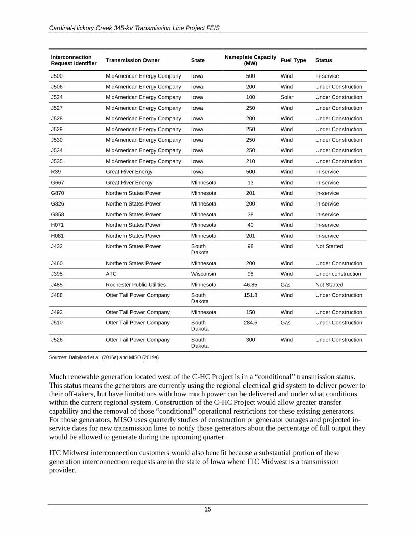
Cardinal-Hickory Creek 345-kV Transmission Line Project FEIS
15
Interconnection Request Identifier Transmission Owner State Nameplate Capacity
(MW) Fuel Type Status
J500 MidAmerican Energy Company Iowa 500 Wind In-service
J506 MidAmerican Energy Company Iowa 200 Wind Under Construction
J524 MidAmerican Energy Company Iowa 100 Solar Under Construction
J527 MidAmerican Energy Company Iowa 250 Wind Under Construction
J528 MidAmerican Energy Company Iowa 200 Wind Under Construction
J529 MidAmerican Energy Company Iowa 250 Wind Under Construction
J530 MidAmerican Energy Company Iowa 250 Wind Under Construction
J534 MidAmerican Energy Company Iowa 250 Wind Under Construction
J535 MidAmerican Energy Company Iowa 210 Wind Under Construction
R39 Great River Energy Iowa 500 Wind In-service
G667 Great River Energy Minnesota 13 Wind In-service
G870 Northern States Power Minnesota 201 Wind In-service
G826 Northern States Power Minnesota 200 Wind In-service
G858 Northern States Power Minnesota 38 Wind In-service
H071 Northern States Power Minnesota 40 Wind In-service
H081 Northern States Power Minnesota 201 Wind In-service
J432 Northern States Power South Dakota
98 Wind Not Started
J460 Northern States Power Minnesota 200 Wind Under Construction
J395 ATC Wisconsin 98 Wind Under construction
J485 Rochester Public Utilities Minnesota 46.85 Gas Not Started
J488 Otter Tail Power Company South Dakota
151.8 Wind Under Construction
J493 Otter Tail Power Company Minnesota 150 Wind Under Construction
J510 Otter Tail Power Company South Dakota
284.5 Gas Under Construction
J526 Otter Tail Power Company South Dakota
300 Wind Under Construction
Sources: Dairyland et al. (2016a) and MISO (2019a)
Much renewable generation located west of the C-HC Project is in a “conditional” transmission status. This status means the generators are currently using the regional electrical grid system to deliver power to their off-takers, but have limitations with how much power can be delivered and under what conditions within the current regional system. Construction of the C-HC Project would allow greater transfer capability and the removal of those “conditional” operational restrictions for these existing generators. For those generators, MISO uses quarterly studies of construction or generator outages and projected in-service dates for new transmission lines to notify those generators about the percentage of full output they would be allowed to generate during the upcoming quarter.
ITC Midwest interconnection customers would also benefit because a substantial portion of these generation interconnection requests are in the state of Iowa where ITC Midwest is a transmission provider.

Cardinal-Hickory Creek 345-kV Transmission Line Project FEIS
16
1.4.1.2 Enable Generation in Southwestern and South-central Wisconsin
In designing the MVP Portfolio, MISO wanted both to increase interstate transmission flows (discussed above) and to facilitate in-state generation development. The construction of the C-HC Project would provide a new substation in southwestern Wisconsin to which new in-state generation could connect.
Renewable generators are requesting to interconnect with or near the C-HC Project in Wisconsin. A 200-MW windfarm (J712) is presently under study at MISO for a potential connection to the new Hill Valley Substation that is part of the C-HC Project. Additionally, three other renewable projects (J855, J870, and J871) have requested interconnection to ATC’s existing Eden Substation near the new Hill Valley Substation. If these projects become operational, it is highly likely that they would be connected at Hill Valley. Because developers sometimes withdraw their requests for interconnection, it is unknown whether any of these renewable generators would interconnect with the new Hill Valley Substation.
Table 1.4-2 shows that there are almost 1,800 MW of generation interconnection requests in southwestern and south-central Wisconsin. Many of these requests, though not directly connecting to the C-HC Project, would likely benefit from C-HC in the form of lower costs to interconnect. The Quilt Block Wind Farm (J395), the output of which is purchased by Dairyland, is conditional on the C-HC Project (MISO 2017c).
Table 1.4-2. Generation Interconnection Requests in Southwestern and South-Central Wisconsin
Project Number
Group Name Point of Interconnection County MW Generating Facility Type In-Service Date
J390 ATC Paddock-Rockdale 345-kV Line Rock 702 Natural Gas Combustion Turbine (Combined Cycle)
4/25/2018
J395 ATC Hillman-Darlington 138-kV Line Lafayette 98 Wind 12/31/2017
J584 ATC Blacksmith Tap-Spring Grove 69-kV Line
Green 60 Wind 9/15/2018
J760 ATC New Kitty Hawk 345-kV Substation
Rock 30 Natural Gas Combustion Turbine (Simple Cycle)
4/1/2019
J807 ATC Darlington-Hillman 138-kV Line (Falcon Substation J395)
Lafayette 41.4 Wind 9/15/2020
J818 ATC Jefferson 138-kV Substation Jefferson 149 Photovoltaic Solar Solar
J819 ATC Darlington 138-kV Substation Lafayette 99.9 Wind 9/15/2020
J850 ATC RCEC La Prairie-RCEC Bradford 138-kV Line
Rock 250 Photovoltaic Solar 9/30/2021
J855 ATC Eden 138-kV Substation Grant, Iowa
100 Wind 8/1/2019
J864 ATC Lone Rock 69-kV Substation Richland 49.98 Photovoltaic Solar 9/1/2019
J870 ATC Eden 138-kV Substation Grant, Iowa
200 Photovoltaic Solar 9/10/2021
J871 ATC Eden 138-kV Substation Grant, Iowa
100 Photovoltaic Solar 9/10/2021
J947 ATC Potosi-Hillman 138-kV Line Grant 200 Photovoltaic Solar 9/15/2019
Source: MISO (2019b)
Cardinal-Hickory Creek 345-kV Transmission Line Project FEIS
17
1.4.2 Reduce the Overall Cost of Delivered Electricity The C-HC Project would significantly help to resolve constraints and allow Dairyland’s and ATC’s customers to access more lower-cost energy in Iowa, while also allowing ITC Midwest’s load-serving transmission customers more access to the energy market to sell lower-cost energy.
Adding a new regional transmission line should also reduce the costs of delivering electricity. The following are metrics for calculating the amount of those savings along with how those metrics apply to the customers of Dairyland, ATC, and ITC Midwest.
1.4.2.1 Energy Cost Savings When a new transmission line or non-transmission alternative is added to the electric system, prices in certain locations of the energy market can be lowered. For example, when a 345-kV alternative like the C HC Project is added to the transmission system, the energy market becomes more robust as energy from different generators can now be transmitted to different load points more efficiently and without constraint, thereby increasing competition and driving down market prices.
Dairyland and ATC’s customers benefit economically in the MISO energy markets in part due to reduced constraints on transmission lines. According to the Utilities’ planning analysis submitted as part of the application to the Wisconsin Public Service Commission, the C-HC Project would provide net benefits to Wisconsin customers of between $22.7 million and $349.3 million (American Transmission Company et al. 2018). These benefits would include energy cost savings, insurance value, avoided reliability upgrades, avoided asset renewal upgrades, and capacity cost savings. Customers of Dairyland, ATC, and other utilities in Wisconsin would share in these benefits.
Dairyland would directly benefit because the C-HC Project would eliminate the Stoneman-Turkey River 161-kV transmission line as a potential market constraint and capacity import limit, thereby increasing the competitiveness of an area that the Independent Market Monitor has deemed a “Narrow Constrained Area” in the Wisconsin Upper Michigan System (Potomac Economics 2018). The C-HC Project would reduce constraints by allowing a more efficient dispatch of generation and would improve Dairyland’s service to its member cooperatives’ load in northeast Iowa, southwestern Wisconsin, and northwest Illinois. In combination with other MVPs, the C-HC Project would enable additional transfer capability while offloading heavily congested paths near the Quad Cities on the Iowa–Illinois border (see Figure 1.3-2).
In Iowa, the C-HC Project would support existing and future wind generation development that would benefit the state and the region through the production of additional low-cost energy.
1.4.2.2 Reduce Capacity and Energy Losses There is a need to reduce capacity and energy losses for electricity delivered for Dairyland’s members and ATC’s customers. All transmission lines have losses because as electricity travels across the conductors from point A to point B some energy is lost as heat. When a transmission project is built, the electric system becomes more robust, and often decreases the capacity and energy losses in the lines since the

Cardinal-Hickory Creek 345-kV Transmission Line Project FEIS
18
electricity that travels through the system now has more conductors and capacity.1 By lowering the line losses during peak demand, the amount of capacity and energy that the local utilities are required to generate and deliver is reduced. This reduction of capacity and energy losses results in electricity being delivered more efficiently and at reduced costs, a direct economic benefit to customers.
MISO has found that the addition of the MVP Portfolio, of which the C-HC Project is one element, to the existing transmission network would reduce overall system losses (MISO 2014). The MVP Portfolio would also reduce the generation needed to serve the combined load and transmission line losses. According to MISO, “the energy value of these loss reductions is considered in the congestion and fuel savings benefits, but the loss reduction also helps to reduce future generation capacity needs.” Fuel savings refers to the offset of natural gas, coals, and other fuel units by wind generation (MISO 2014:37).
1.4.2.3 Improve Competitiveness A new transmission facility can improve the market structure and competitiveness if the facility enables external suppliers to offer additional generation into a specifically defined market. The increased generation alternatives would increase competition, causing a reduction in market prices. To the extent that suppliers who participate in the market are exposed to such market prices through short-term purchases and the turnover of longer-term contracts, these reductions in market prices would also reduce end-user costs.
1.4.3 Address Reliability Issues on the Regional Bulk Transmission System
The Nelson Dewey (nameplate 220 MW) and Stoneman (nameplate 40 MW) power plants in Cassville, Wisconsin, both ceased operations in 2015. These plant closures have changed the electricity flows on the regional grid in southwestern Wisconsin and have increased the reliance on the local transmission system due to the need to bring electricity from more remote generation sources to maintain local electric service. Because of these plant closings, Dairyland, ATC, and MISO have had to establish operating guides to control how much power flows through the transmission lines in southwestern Wisconsin under certain operating conditions.
An operating guide consists of pre-planned procedures that are initiated under pre-determined operating conditions of the transmission system to alleviate conditions such as line overloads. Operating guides are normally used as interim measures and are not normally long-term solutions. The C-HC Project would reduce or completely eliminate multiple operating guides, some of which exist due to the risk of cascading outages in southwestern and south-central Wisconsin for some contingencies. While operating guides may be an acceptable way to maintain a reliable transmission system, they do add complexity to real-time operations and, in some instances, require reliability to be maintained by interrupting service to load or generation. It is a clear benefit to limit the number of operating guides and/or the complexity within each operating guide.
There are several transmission line overloads in southwestern and south-central Wisconsin. The three most serious overloads that must be eliminated under NERC requirements occur on the:
1 A conductor is a wire made up of multiple aluminum strands around a steel core that together carry electricity. Capacity is defined as the maximum allowable value of current that can flow through transmission lines without adversely affecting the mechanical and electrical properties of the conductor. Capacity size depends on the electrical and mechanical properties of the conductor, its ability to spread the heat generated, and the ambient conditions (Spes et al. 2017). Transmitting electricity at a higher voltage reduces the losses in the conductor. Generally speaking, the more energy that travels across the conductors, the hotter they become and the more energy is dissipated as lost heat. When a new transmission line is built, it generally reduces the amount of energy that travels over the existing transmission lines, thereby decreasing line losses.

Cardinal-Hickory Creek 345-kV Transmission Line Project FEIS
19
• Turkey River–Stoneman 161-kV transmission line, connecting ITC Midwest to Dairyland;
• Stoneman-Nelson Dewey 161-kV transmission line; and
• Townline Road-Bass Creek 138-kV transmission line.
The Utilities have also identified 46 existing overloads that would be eliminated by the C-HC Project. Furthermore, MISO also documented overloads that would be eliminated by the MVP Portfolio (MISO 2014, 2017a).
1.4.4 Avoided Infrastructure Costs and Other Grid Improvements There is a need to upgrade and/or replace existing, aging infrastructure within the study area. If the C-HC Project is not constructed, Dairyland would, at a minimum, have to rebuild the Stoneman-Nelson Dewey 161-kV transmission line to increase its capability and also would have to replace equipment at the Stoneman Substation to increase the capability of the Turkey River-Stoneman 161-kV line (Dairyland et al. 2016a).
Analysis completed as part of MISO’s MVP Portfolio review indicates that the Turkey River-Stoneman 161-kV line may need to be rebuilt as a 345-kV line, which is currently considered part of the C-HC Project. This improvement may be needed in the future if the C-HC Project is not built.
Other transmission line improvement that are needed within the general study area are listed in Table 1.4-3.
Table 1.4-3. Transmission Projects Eliminated as a Result of the Cardinal-Hickory Creek Project
Transmission Project Length (miles) Transmission Owner
Turkey River – Stoneman 161-kV 2.71 Dairyland and ITC Midwest
North Monroe – Albany 138-kV 9.21 ATC
Albany – Bass Creek 138-kV 11.88 ATC
Total 23.80
1.5 PURPOSE OF AND NEED FOR FEDERAL ACTION Several agencies will use this FEIS to inform decisions about funding, authorizing, or permitting various components of the proposed C-HC Project. RUS, the lead Federal agency, will determine whether or not to provide financial assistance for Dairyland’s portion of the project. As a cooperating agency, the USFWS will evaluate the Utilities’ request for a right-of-way (ROW) easement and a Special Use Permit to cross the Refuge. The USACE, also a cooperating agency, will review a ROW request as well as permit applications and requests for permission by the Utilities, as required by Section 10 and Section 408 of the Rivers and Harbors Act and Section 404 under the Clean Water Act (CWA). The following sections describe the authorities under which the three Federal agencies can make decisions and the type of decisions to be made.
1.5.1 Rural Utilities Service The Rural Electrification Act of 1936, as amended (7 U.S.C. 901 et seq.) generally authorizes the Secretary of Agriculture to make rural electrification and telecommunication loans, and specifies eligible
Cardinal-Hickory Creek 345-kV Transmission Line Project FEIS
20
borrowers, references, purposes, terms and conditions, and security requirements. RUS is authorized to make loans and loan guarantees to finance the construction of electric distribution, transmission, and generation facilities including system improvements and replacements required to furnish and improve electric service in rural areas, as well as demand-side management, electricity conservation programs, and on- and off-grid renewable electricity systems.
Dairyland is requesting financing assistance from RUS for its participation as a partial owner of the C-HC Project. Dairyland would be the sole owner of the 161-kV transmission line that would be rebuilt as part of the 345-kV Mississippi River crossing and any equipment replaced in the Stoneman Substation. Dairyland also would be a partial owner of the Turkey River Substation. RUS’s proposed Federal action is to decide whether to provide financial assistance for Dairyland’s participation as a partial owner of the C- HC Project.
As part of its review process, RUS is required to complete the NEPA process, along with other technical and financial considerations, in processing Dairyland’s application. Other RUS agency actions include the following:
• Provide engineering reviews of the purpose and need, engineering feasibility, and cost of the proposed project.
• Ensure that the proposed project meets the borrower’s requirements and prudent utility practices.
• Evaluate the financial ability of the borrower to repay its potential financial obligations to RUS.
• Review the alternatives to improve transmission reliability issues.
• Ensure that adequate transmission service and capacity are available to meet the proposed project needs.
• Ensure that NEPA and other environmental laws and requirements and RUS environmental policies and procedures are satisfied prior to taking a Federal action.
1.5.2 U.S. Fish and Wildlife Service The USFWS would need to issue a Special Use Permit for construction of project features on Refuge-managed/owned lands and may need to authorize additional or new ROW for crossing the Refuge. The USFWS is authorized to approve permits and issue easements for utilities under 16 U.S.C. 668dd(d)(1)(b). The Refuge is part of the National Wildlife Refuge System (NWRS). The mission of the NWRS is defined in the Refuge Improvement Act of 1997 as:
to administer a national network of lands and waters for the conservation, management and where appropriate, restoration of fish, wildlife and plant resources and their habitats within the United States for the benefit of present and future generations of Americans.
The Upper Mississippi River Wildlife and Fish Refuge Act of 1924 sets forth the following purposes for the Refuge:
…as a refuge and breeding place for migratory birds included in the terms of the convention between the United States and Great Britain for the protection of migratory birds, concluded August 16, 1916, and

Cardinal-Hickory Creek 345-kV Transmission Line Project FEIS
21
to such extent as the Secretary of the Interior may by regulations prescribe, as a refuge and breeding place for other wild birds, game animals, fur-bearing animals, and for the conservation of wild flowers and aquatic plants, and
to such extent as the Secretary of the Interior may by regulations prescribe as a refuge and breeding place for fish and other aquatic animal life.
USFWS also has authority and trust responsibility under the Endangered Species Act (ESA), the Bald and Golden Eagle Protection Act, and the Migratory Bird Treaty Act.
USFWS would need to grant an easement across its lands within the Refuge for the C-HC Project. The Utilities have submitted a ROW application for crossing the Refuge. The Refuge Manager has completed a written draft compatibility determination for the proposed C-HC Project. The compatibility determination is available for public comment and included as Appendix J. Compatible use is defined in 50 CFR 25.12(a) as “a proposed or existing wildlife-dependent recreational use or any other use of national wildlife refuge that, based on sound professional judgment, will not materially interfere with or detract from the fulfillment of the National Wildlife Refuge System mission or the purpose(s) of the national wildlife refuge.”
A Special Use Permit would be needed from the Refuge prior to construction of the project on Refuge-managed/owned lands after a ROW is issued.
Under NEPA and the National Wildlife Refuge Improvement Act of 1997, major actions affecting the quality of the human environment require full consideration of potential impacts, public involvement, and an interdisciplinary approach to decision-making that considers a reasonable range or alternatives.
1.5.3 U.S. Army Corps of Engineers The USACE may need to issue the following authorizations and permits to allow the C-HC Project to be constructed:
• A permit under Section 10 of the Rivers and Harbors Act, for the crossing of the Mississippi River.
• Permission under Section 14 of the Rivers and Harbors Act (commonly referred to as “Section 408”), for the crossing of the Mississippi River.
• A permit under Section 404 of the CWA, for activities that discharge fill into waters of the U.S. (WUS), including wetlands.
• A ROW authorization to issue an easement across USACE-owned lands.
Section 10 of the Rivers and Harbors Act of 1899 is administered by the USACE. Under Section 10, a permit is required to construct certain structures or to work in or affect “navigable waters of the U.S.” Navigable WUS are defined by the USACE as:
those waters of the United States subject to the ebb and flow of the tide and/or are presently used, or have been used in the past, or may be susceptible to use to transport interstate or foreign commerce. A determination of navigability, once made, applies laterally over the entire surface of the waterbody, and is not extinguished by later actions or events which impede or destroy navigable capacity (33 CFR Part 329).

Cardinal-Hickory Creek 345-kV Transmission Line Project FEIS
22
Section 10 requires a minimum clearance over the navigable channel for an aerial electric transmission line crossing navigable WUS. Within the C-HC Project area, the Mississippi River is considered to be navigable WUS.
Section 14 of the Rivers and Harbors Act of 1899, as amended, and codified in 33 U.S.C. 408 (Section 408) provides that the Secretary of the Army may, upon the recommendation of the Chief of Engineers, grant permission to other entities for the permanent or temporary alteration or use of any USACE Civil Works project. Permission under Section 14 of the River and Harbors Act applies to USACE real estate, such as USACE-owned lands, that are found within the Refuge. USACE Engineer Circular (EC) 1165-2-216, Policy and Procedural Guidance for Processing Requests to Alter U.S. Army Corps of Engineers Civil Works Projects Pursuant to 33 USC 408, provides the requirements and procedures for an overall review process that can be tailored to the scope, scale, and complexity of individual proposed alterations, and provides infrastructure-specific considerations for dams, levees, floodwalls, flood risk management channels, and navigation projects. Per EC 1165-2-216, the decision made by the USACE pursuant to a Rivers and Harbors Act Section 10 permit or CWA Section 404 permit cannot be issued prior to the decision on the Section 408 permit.
Section 404 of the CWA established a permit program for the discharge of dredged or fill material into WUS, including wetlands. This permit program is jointly administered by the USACE and the USEPA. The immediate regulatory decision regarding which activities fall under Section 404 of the CWA lies with the USACE Rock Island District in Illinois, and St. Paul District in Wisconsin. The USACE will need to determine which method for obtaining a Section 404 permit applies to the C-HC Project: authorization under a Nationwide Permit (NWP), authorization under a regional general permit, or issuance of an individual permit.
The USACE’s evaluation of a Section 10 permit and Section 14 permission under the Rivers and Harbors Act and a Section 404 permit under the CWA involves multiple analyses, including: 1) evaluating the C-HC Project’s impacts in accordance with NEPA, 2) determining whether the C-HC Project is contrary (Section 10 and possibly Section 14) to the public interest, and 3) in the case of the Section 404 permit, determining whether the C-HC Project complies with the requirements of the CWA.
The issuance of a ROW easement would require an application to the USACE Real Estate branch that demonstrates the project has no viable alternative to use of public lands and has a demonstrated need. The C-HC Project would be reviewed to determine if it is consistent with Mississippi River Project purposes, consistent with the Mississippi River Project Master Plan, and meets applicable laws/guidance. An approved mitigation plan for statutory and non-statutory mitigation may also be required before issuance.
1.6 REQUIRED FEDERAL AND STATE AGENCY APPROVALS The Utilities will be required to obtain approvals from multiple Federal and state agencies prior to constructing the C-HC Project. For the Mississippi River crossing, the C-HC Project must obtain approvals from multiple Federal agencies, as described above under Section 1.5, Purpose of and Need for Federal Action. The C-HC Project must also obtain authorizations from the States of Iowa and Wisconsin. These requirements are briefly described below.
1.6.1 Federal and State Permits and Approvals Summary Table 1.6-1 identifies the primary permits and other approvals that may be required by Federal and state agencies.
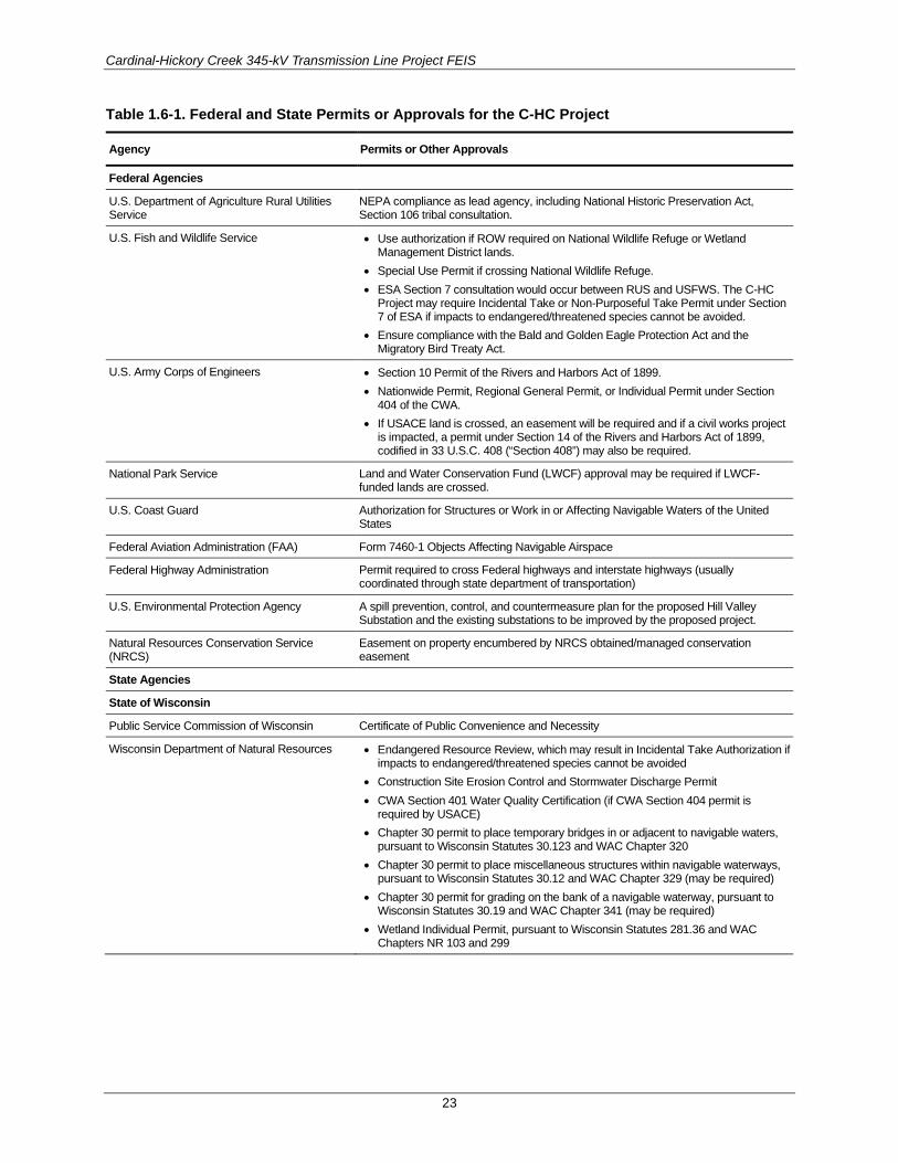
Cardinal-Hickory Creek 345-kV Transmission Line Project FEIS
23
Table 1.6-1. Federal and State Permits or Approvals for the C-HC Project
Agency Permits or Other Approvals
Federal Agencies
U.S. Department of Agriculture Rural Utilities Service
NEPA compliance as lead agency, including National Historic Preservation Act, Section 106 tribal consultation.
U.S. Fish and Wildlife Service • Use authorization if ROW required on National Wildlife Refuge or Wetland Management District lands.
• Special Use Permit if crossing National Wildlife Refuge. • ESA Section 7 consultation would occur between RUS and USFWS. The C-HC
Project may require Incidental Take or Non-Purposeful Take Permit under Section 7 of ESA if impacts to endangered/threatened species cannot be avoided.
• Ensure compliance with the Bald and Golden Eagle Protection Act and the Migratory Bird Treaty Act.
U.S. Army Corps of Engineers • Section 10 Permit of the Rivers and Harbors Act of 1899. • Nationwide Permit, Regional General Permit, or Individual Permit under Section
404 of the CWA. • If USACE land is crossed, an easement will be required and if a civil works project
is impacted, a permit under Section 14 of the Rivers and Harbors Act of 1899, codified in 33 U.S.C. 408 (“Section 408”) may also be required.
National Park Service Land and Water Conservation Fund (LWCF) approval may be required if LWCF-funded lands are crossed.
U.S. Coast Guard Authorization for Structures or Work in or Affecting Navigable Waters of the United States
Federal Aviation Administration (FAA) Form 7460-1 Objects Affecting Navigable Airspace
Federal Highway Administration Permit required to cross Federal highways and interstate highways (usually coordinated through state department of transportation)
U.S. Environmental Protection Agency A spill prevention, control, and countermeasure plan for the proposed Hill Valley Substation and the existing substations to be improved by the proposed project.
Natural Resources Conservation Service (NRCS)
Easement on property encumbered by NRCS obtained/managed conservation easement
State Agencies
State of Wisconsin
Public Service Commission of Wisconsin Certificate of Public Convenience and Necessity
Wisconsin Department of Natural Resources • Endangered Resource Review, which may result in Incidental Take Authorization if impacts to endangered/threatened species cannot be avoided
• Construction Site Erosion Control and Stormwater Discharge Permit • CWA Section 401 Water Quality Certification (if CWA Section 404 permit is
required by USACE) • Chapter 30 permit to place temporary bridges in or adjacent to navigable waters,
pursuant to Wisconsin Statutes 30.123 and WAC Chapter 320 • Chapter 30 permit to place miscellaneous structures within navigable waterways,
pursuant to Wisconsin Statutes 30.12 and WAC Chapter 329 (may be required) • Chapter 30 permit for grading on the bank of a navigable waterway, pursuant to
Wisconsin Statutes 30.19 and WAC Chapter 341 (may be required) • Wetland Individual Permit, pursuant to Wisconsin Statutes 281.36 and WAC
Chapters NR 103 and 299

Cardinal-Hickory Creek 345-kV Transmission Line Project FEIS
24
Agency Permits or Other Approvals
Wisconsin Department of Transportation • Application to Construct and Operate and Maintain Utility Facilities on Highways Rights-of-Way (Form DT1553)
• Access Driveway Permit (may be required) • Drainage Permit (may be required) • Road Crossing Authorization • Oversize Loads or Excessive Weights on Highways
Wisconsin Historical Society, Office of Preservation Planning
National Historic Preservation Act, Section 106 consultation
Wisconsin Department of Agriculture, Trade and Consumer Protection (DATCP)
Agricultural Impact Statement
State of Iowa
Iowa Utility Board and Iowa municipality, if crossed
Electric Transmission Line Franchise
Iowa Department of Natural Resources • CWA Section 401 Water Quality Certification (if CWA Section 404 permit is required by the U.S. Army Corps of Engineers)
• National Pollutant Discharge Elimination System (NPDES) Permit • Floodplain Development Permit • Sovereign Land Construction Permit
Iowa Department of Transportation Utility Accommodation Permit; Work within Right-of-Way Permit
Iowa State Historic Preservation Office National Historic Preservation Act, Section 106 consultation
1.6.2 Certificate of Public Convenience and Necessity in Wisconsin
In addition to compliance with all applicable Federal regulations, a certificate of public convenience and necessity (CPCN) must be granted by the State of Wisconsin. The Public Service Commission of Wisconsin (PSCW) is responsible for reviewing and approving applications for a transmission project that is either 1) 345 kV or greater, or 2) less than 345 kV but greater than or equal to 100 kV, over 1 mile in length, and needing a new ROW (PSCW 2017).
The size and complexity of a proposed project determines the review process. When reviewing a transmission project, the PSCW considers alternative sources of supply and alternative locations or routes, as well as the need, engineering, economics, safety, reliability, individual hardships, and potential environmental effects. Applicants need to provide detailed information for two possible routes for projects that require a CPCN. Proposed routes are often subdivided into various route segments. (PSCW 2017).
After an CPCN application has been filed, the PSCW notifies the public that the review process is beginning. A public notification letter is sent to all property owners on or near the proposed ROW, as well as local government officials, libraries, and other interested persons. The notification describes the proposed project, includes a map, identifies the level of environmental review the project requires, lists locations where copies of the application are available for review, solicits public comments, and provides contact information. All transmission project applications are reviewed for environmental impacts, electrical performance, need, and cost/benefit (PSCW 2017). The Utilities’ CPCN application for the C-HC Project was deemed completed by the PSCW on October 4, 2018.
The PSCW will prepare an EIS to assess how the project would affect the natural and human environment. The EIS includes all of the relevant knowledge and information about the expected

Cardinal-Hickory Creek 345-kV Transmission Line Project FEIS
25
environmental effects acquired by reviewing the project application and peer-reviewed literature, visiting the project area, interviewing regulatory staff with experience with similar projects, consulting other agencies, and collecting public comments. The PSCW issued their Draft EIS for the C-HC Project on February 28, 2019, and the Final EIS on May 8, 2019. Projects for which an EIS is prepared always require a public hearing in the project area (PSCW 2017). The PSCW held public hearings for the C-HC Project on June 25–27, 2019.
Members of the public are encouraged to testify about their views and concerns at public hearings. Public testimony may be provided in person at the hearing or through comments submitted to the PSCW by mail or on a dedicated project website at the PSCW after the hearing notice is issued. All testimony provided at public hearings is included in the record that the PSCW reviews in making a decision (PSCW 2017).
The PSCW is responsible for making the final decisions regarding proposed transmission lines in Wisconsin. The commissioners review the application, the case record, the environmental document prepared by staff, memos, and briefs. The PSCW discusses the issues raised in the hearing and makes its decision in an open meeting (PSCW 2017). On September 26, 2019, the PSCW issued the written order for the selected route, which primarily follows the Utilities’ preferred route submitted in their CPCN application. The selected route includes three minor route modifications at the following locations:
• East of Montfort, Wisconsin along U.S. Highway 18;
• West of Barneveld, Wisconsin along U.S. Highway 18; and
• South of Cross Plains, Wisconsin near the intersection of Stagecoach Road and County Road P.
The PSCW decides whether a transmission line should be built, how it should be designed, and where it would be located. All proposed routes are analyzed during review by the PSCW. The selected route, chosen by the PSCW, may be the applicant’s preferred route, an alternative route offered by the applicant, a combination of reasonable route segments, or a route variation suggested by the public. The PSCW’s decisions are described in a detailed written order to the project applicant(s) (PSCW 2017).
According to Wisconsin’s eminent domain law (Wisconsin Statute section 32.03(5)), a transmission owner generally may not acquire an easement for transmission projects requiring a CPCN until it receives the CPCN from the PSCW. The PSCW determines the transmission line route and structure designs that should be used after reviewing the record of the public hearing for the CPCN. However, Wisconsin Statute section 32.03(5)(c) does allow a transmission owner to negotiate an easement with a landowner before a CPCN is issued if the transmission owner advises the landowner that it doesn’t have authority to acquire the property by condemnation until the CPCN actually is issued (PSCW 2015).
For the C-HC Project, RUS has been coordinating closely with the PSCW to help ensure that if the C-HC Project is approved, the Federal and state processes result in the selection of a complete route that connects the Cardinal Substation in Wisconsin with the Hickory-Creek Substation in Iowa.
1.6.3 Electric Transmission Franchise in Iowa In addition to complying with all applicable Federal regulations, the C-HC Project must have an electric transmission franchise granted by the State of Iowa. The Iowa Utilities Board (IUB) is responsible for reviewing and processing all petitions for electric transmission line franchises under Iowa Code Chapter 478 – Electric Transmission Lines, Chapter 11 of 199 Iowa Administrative Code – Electric Lines, and Chapter 25 of 199 Iowa Administrative Code – Iowa Electrical Safety Code. A franchise is the authorization of the IUB for the construction, erection, maintenance, and operation of an electric transmission line. The granting of a franchise requires a finding by the IUB that the project is necessary

Cardinal-Hickory Creek 345-kV Transmission Line Project FEIS
26
to serve a public use, represents a reasonable relationship to an overall plan of transmitting electricity in the public interest, and meets all other legal requirements (IUB 2017).
Any electric line which operates at 69 kV or more and is located outside the boundaries of a city requires a franchise from the IUB (Iowa Code Section 478.1). A company seeking a franchise can also request that the IUB grant the right of eminent domain, or condemnation, to obtain the ROW needed for the project (IUB 2017).
Iowa Code requires that an informational meeting must be held for any electric transmission line that would extend for 1 mile or more on privately owned land. The company proposing the electric line is required to notify all parties with an ownership interest in possibly affected property of the meeting. The company cannot begin ROW negotiations with landowners until this meeting is held and cannot petition the IUB for a franchise until at least 30 days after this meeting (IUB 2017). The Utilities held two informational meetings for the C-HC Project on March 29, 2018.
After a petition is filed, there is a period of staff review and company responses to public comment letters before the proceeding moves forward. Once staff determines the petition is satisfactory from a technical standpoint, there are two procedural paths toward an IUB decision. If no objections are on file and the petition does not request eminent domain, a notice is published for 2 consecutive weeks in a newspaper in the county (or counties) where construction would occur. If no objections are filed within 20 days of the second publication, a franchise may be granted without a hearing. If objections are on file, or if eminent domain is requested, a hearing typically is held. Notice of the hearing will be published, and objectors and/or owners of eminent domain parcels will receive notice by mail. Written testimony will be pre-filed, and a hearing held for cross examination. The hearing may be conducted by the IUB, or by an Administrative Law Judge or Presiding Officer. If the hearing is not held before the full IUB, the result will be a proposed decision that can be appealed to the full IUB (IUB 2017). The Utilities submitted the petition to the IUB for the C-HC Project on May 11, 2018. The IUB public hearing is scheduled for December 10– 12, 2019.
Following the hearing, parties may file post-hearing briefs, and then the IUB issues its final decision. If the IUB approves the granting of the franchise, the company proposing the electric line may begin construction activities as defined by the final ruling of the IUB.
Once the IUB has decided the case, either initially or on appeal from a proposed decision, any party to the proceeding may file for rehearing within 20 calendar days under Iowa Code Sections 17A.16 and 478.32. Once a final decision has been made, any party may appeal to the District Court within 30 days under Iowa Code Sections 17A.19 and 478.32. A request for rehearing is not required prior to taking an appeal (IUB 2017).
1.7 PUBLIC PARTICIPATION FOR FEDERAL DECISIONS The first Notice of Intent (NOI) for the C-HC Project was published in the Federal Register on October 18, 2016. The NOI serves as the official public announcement of the intent to prepare an EIS. The NOI published on October 18, 2016, initiated the 30-day public scoping period, which ultimately was extended to 81 days ending on January 6, 2017. The announcement included a brief overview about the Proposed Action and alternatives, potential resource concerns, opportunities to provide input and attend meetings, and RUS project contacts.
On November 22, 2016, RUS published a second NOI, which announced the second round of public scoping meetings held on December 6 and 7, 2016.

Cardinal-Hickory Creek 345-kV Transmission Line Project FEIS
27
1.7.1 Public Notification Efforts A combination of legal announcements, display ads, and press releases were provided to newspapers, television stations, and radio stations servicing the project area during the public scoping period to provide public scoping meeting details, the scoping period deadline, and basic details about the C-HC Project to individuals within the project vicinity. Details about the information provided to media outlets can be found in the C-HC Scoping Report (SWCA Environmental Consultants [SWCA] 2017).
On October 14, 2016, letters were sent to 38 Federal and state agencies inviting them to participate in public and agency scoping meetings concurrently with the public scoping meetings in October and November 2016. Agency scoping meetings were also scheduled to provide updates and answer questions. Iowa agencies were invited to attend a meeting in Peosta, Iowa, on October 31, 2016. Wisconsin agencies were invited to attend a meeting in Middleton, Wisconsin, on November 3, 2016. On November 17, 2016, letters were mailed to a slightly expanded list of 46 Federal and state agencies notifying them of the second round of public scoping meetings held on December 6 and 7, 2016.
RUS and the SWCA team began notifying federally recognized tribes with interest in the C-HC Project area about the EIS process with letters sent via registered mail on October 17, 2016, for the first set of public scoping meetings, and on November 17, 2016, for the second set of public scoping meetings (see Appendix B). The letters mailed in October and November 2016, invited the tribes to participate in the National Historic Preservation Act Section 106 review process, attend public scoping meetings, and provide relevant information for inclusion in the EIS. RUS and the SWCA team coordinated and documented activities and input received during the Section 106 review process. The team limited information included in the administrative record to that which was not considered sensitive by the tribes.
In response to feedback provided to RUS after the first set of public scoping meetings in October and November 2016, RUS provided a direct mailing to 66 local government contacts on November 17, 2016, to notify them of the second round of public scoping meetings held on December 6 and 7, 2016.
1.7.2 Public Scoping Meetings RUS held six public scoping meetings to present the RUS NEPA process and timelines, and to answer questions and receive comments regarding the C-HC Project. Table 1.7-1 summarizes the meeting dates, times, locations, and estimated public attendance based on the meeting sign-in sheets. These five meeting locations are within or near the alternative transmission line corridors.
Table 1.7-1. First Public Scoping Meeting Dates, Times, and Locations
Date Time Location/Venue Public Attendance
October 31, 2016 3:00–6:00 p.m. Peosta Community Centre 7896 Burds Road Peosta, IA 53068
7
November 1, 2016 4:00–7:00 p.m. Cassville Middle School Cafeteria 715 East Amelia Street Cassville, WI 53806
23
November 2, 2016 4:00–7:00 p.m. Dodgeville Middle School Cafeteria 951 Chapel Street Dodgeville, WI 53533
142
November 3, 2016 4:00–7:00 p.m. Madison Marriott West 1313 John Q Hammons Drive Middleton, WI 53562
66

Cardinal-Hickory Creek 345-kV Transmission Line Project FEIS
28
Date Time Location/Venue Public Attendance
December 6, 2016 4:00–7:00 p.m. Peosta Community Centre 7896 Burds Road Peosta, IA 53068
17
December 7, 2016 4:00–7:00 p.m. Deer Valley Lodge 401 West Industrial Drive Barneveld, WI 53507
110
1.7.3 Scoping Comments Received In total, 379 comment letters from 352 commenters were received during the scoping period beginning on October 18, 2016, and ending on January 6, 2017. Government entities and organizations submitting comments are listed in Table 1.7-2 through Table 1.7-4. All other commenters were individuals. Public comments were submitted using comment forms, letters, and emails.
Table 1.7-2. Federal Entities and Federally Recognized Tribes that Submitted Comments
Miami Tribe of Oklahoma U.S. Environmental Protection Agency
National Park Service U.S. House Representative (Wisconsin 2nd Congressional District)
U.S. Army Corps of Engineers U.S. Senator
Table 1.7-3. State and Local Entities that Submitted Comments
Iowa State Historic Preservation Office City of Dubuque, IA
Iowa Department of Natural Resources Town of Stark, WI Energy Planning Information Committee (EPIC)
Iowa Department of Cultural Affairs City of Platteville, WI
Town of Springdale, WI Town of Vermont, WI
Village of Mount Horeb, WI Town of Arena, WI Planning Commission
Town of Belmont, WI Platteville Township, WI
Table 1.7-4. Non-Governmental Organizations that Submitted Comments
Iowa Environmental Council Black Earth Creek Watershed Association
Environmental Law & Policy Center Ice Age Trail Alliance
Iowa Chapter of the Sierra Club Wisconsin Nature Conservancy
Center for Rural Affairs Wisconsin COUNTS (Citizens Opposed to Unnecessary Transmission Lines)
Vermont Citizens Powerline Action Committee Trout Unlimited
Driftless Area Land Conservancy The Prairie Enthusiasts
Minnesota Center for Environmental Advocacy Town of Wyoming WI
The RUS Scoping Report identified 1,736 individual comments contained within the 379 comment letters (SWCA 2017). A summary of the public comments received and organized by concern, issue, or resource topic is presented in Table 1.7-5, in order of the greatest number of comments received to the fewest number of comments received. It is possible that comments addressed multiple topics; therefore, comments may be included in multiple topics below.

Cardinal-Hickory Creek 345-kV Transmission Line Project FEIS
29
Table 1.7-5. Summary of Public Scoping Comments Received, by Topic
Topic Number of Comments
Socioeconomics 552
NEPA Process 481
Wildlife 262
Land Use 169
Visual Resources 162
Recreation and Natural Areas 116
Water Resources 112
Vegetation 112
Public Health and Safety 71
Decision Process 61
Impact Analyses 51
Cultural Resources 39
Air Quality 30
Public Involvement 29
Geology 28
Soils 19
Transportation 16
Noise 14
Communications Infrastructure 5
Paleontology 1
Total 2,330
The C-HC Project scoping report (SWCA 2017) provides a detailed discussion of all public comments received, comment categories, and representative comments for each category identified below. The scoping report is available at the RUS project website: https://www.rd.usda.gov/publications/environmental-studies/impact-statements/cardinal-%E2%80%93-hickory-creek-transmission-line
1.7.4 DEIS Public Comment Period RUS published the Notice of Availability (NOA) for the DEIS in the Federal Register on December 17, 2018. The NOA serves as the official public announcement of the release of the DEIS and announced that RUS will hold six public meetings within the project area. The NOA initiated the 60-day public comment period, scheduled to conclude on February 5, 2019. The public comment period was extended to 116 days, ending on April 1, 2019, due to a partial lapse in Federal government funding (December 22, 2018 through January 25, 2019). On February 12, 2019, RUS published a notice in the Federal Register, which extended the public comment period to April 1, 2019. On February 27, 2019, RUS published a notice of rescheduled public meetings for 2 weeks in March.
A combination of legal announcements, display ads, and press releases was provided to newspapers, television stations, and radio stations during the DEIS public comment period and public comment meetings to notify the public about meeting details, the public comment period deadline, and basic details

Cardinal-Hickory Creek 345-kV Transmission Line Project FEIS
30
about the project within the project vicinity. Five rounds of legal notices and display ads were placed in newspapers to notify the public of the DEIS, how to comment on the DEIS, information about the six public meetings, and scheduling information. For more details refer to Appendix F.
RUS held six rescheduled meeting throughout the project area. The meetings were to provide an overview of the C-HC Project DEIS, present the RUS NEPA process and timelines, and to receive comments regarding the DEIS. Table 1.7-6 summarizes the meeting dates, times, locations, and estimated public attendance based on the meeting sign-in sheets.
Table 1.7-6. DEIS Public Comment Meeting Dates, Times, and Locations
Date Time Location/Venue Public Attendance
March 13, 2019 5:00–7:00 p.m. Dodger Bowl Banquet Hall 318 King Street Dodgeville, WI 53533
96
March 14, 2019 5:00–7:00 p.m. Deer Valley Lodge 401 West Industrial Drive Barneveld, WI 53507
76
March 15, 2019 5:00–7:00 p.m. Guttenberg Municipal Building 502 S. First Street Guttenberg, IA 52052
14
March 18, 2019 5:00–7:00 p.m. Cassville Middle School Cafeteria 715 E. Amelia Street Cassville, WI 53806
23
March 19, 2019 5:00–7:00 p.m. Peosta Community Center 7896 Burds Road Peosta, IA 53068
18
March 20, 2019 5:00–7:00 p.m. Madison Marriott West 1313 John Q Hammons Drive Middleton, WI 53562
78
1.7.5 DEIS Public Comments Received A total of 401 comment submittals (letters, emails, commenters at hearings) was provided to the RUS on the DEIS; within the submittals, there were 2,686 individual comments. Seven of these 401 comment letters were duplicate letters, and 54 were form letters or a variation of a form letter. All comments that were received became a part of the administrative record and were entered into an interactive, searchable table and coded to reflect the subject matter of concern, sorted, and summarized. Appendix F of the FEIS includes all DEIS comments and agency responses to these comments in tabular format.
RUS has reviewed the 2,039 individual comments contained within the comment letters (excluding duplicates and form letter copies). A summary of the public comments received and organized by concern, issue, or resource topic is presented in Table 1.7-7, in order of the greatest number of comments received to the least number of comments received. It is possible that comments addressed multiple topics; therefore, comments may be included in multiple topics below.
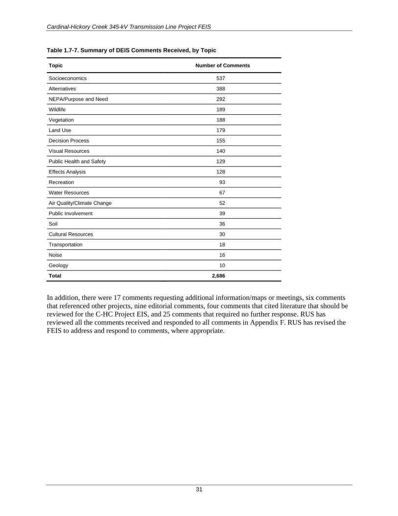
Cardinal-Hickory Creek 345-kV Transmission Line Project FEIS
31
Table 1.7-7. Summary of DEIS Comments Received, by Topic
Topic Number of Comments
Socioeconomics 537
Alternatives 388
NEPA/Purpose and Need 292
Wildlife 189
Vegetation 188
Land Use 179
Decision Process 155
Visual Resources 140
Public Health and Safety 129
Effects Analysis 128
Recreation 93
Water Resources 67
Air Quality/Climate Change 52
Public Involvement 39
Soil 36
Cultural Resources 30
Transportation 18
Noise 16
Geology 10
Total 2,686
In addition, there were 17 comments requesting additional information/maps or meetings, six comments that referenced other projects, nine editorial comments, four comments that cited literature that should be reviewed for the C-HC Project EIS, and 25 comments that required no further response. RUS has reviewed all the comments received and responded to all comments in Appendix F. RUS has revised the FEIS to address and respond to comments, where appropriate.

Cardinal-Hickory Creek 345-kV Transmission Line Project FEIS
32
This page intentionally left blank.

CHAPTER 2. PROPOSED PROJECT AND ALTERNATIVES Under NEPA regulations established by the Council on Environmental Quality (CEQ), this FEIS identifies and evaluates reasonable alternatives to the proposed project, as well as the No Action Alternative. Reasonable alternatives are those that are “practical or feasible from the technical and economic standpoint and using common sense, rather than simply desirable from the standpoint of the applicant” (CEQ 1981: Question 1) (40 CFR 1502.14). In determining reasonable alternatives, RUS considered a number of factors such as the Proposed Action’s purpose and need (described in Chapter 1), state of the art technology, economic considerations, legal considerations, comments received during the scoping period, availability of resources, and the time frame in which the identified need must be fulfilled.
This chapter describes the C-HC Project and includes information about how alternatives were developed. It also describes alternatives evaluated in this FEIS, including the proposed project and action alternatives, the No Action Alternative, and those alternatives that were considered but not included for detailed analysis.
2.1 DEVELOPMENT OF ALTERNATIVES RUS regulations (7 CFR 1970.5 (b)(3)(iii)) require the Utilities to “develop and document reasonable alternatives that meet their purpose and need while improving environmental outcomes.” As part of the initial investigation of the proposed C-HC Project, the Utilities prepared three corridor-siting documents: the Alternatives Evaluation Study (AES) (Dairyland et al. 2016a), the Alternative Crossings Analysis (ACA) (Burns and McDonnell Engineering Company [Burns and McDonnell] 2016), and the Macro-Corridor Study (MCS) (Dairyland et al. 2016b). The Utilities’ reports can be found on the RUS project website:
https://www.rd.usda.gov/publications/environmental-studies/impact-statements/cardinal-%E2%80%93-hickory-creek-transmission-line
The reports are also available on the Utilities’ project website:
https://www.cardinal-hickorycreek.com/
The AES describes the Utilities’ rationale for the proposed C-HC Project, the Utilities’ purpose of and need for the action, and the technological means to meet the Utilities’ purpose and need. The AES describes the transmission planning process and modeling scenarios used by MISO to evaluate electrical alternatives and to identify the project endpoints: the Hickory Creek Substation in Iowa, and the Cardinal Substation in Wisconsin. The Utilities then developed the C-HC Study Area to develop a range of reasonable route alternatives connecting the two endpoints. As stated in the AES (Dairyland et al. 2016a:41–42):
MISO approved a line connecting the Hickory Creek 345-kV substation on the Salem-Hazelton 345-kV transmission line in Iowa to the Cardinal Substation in Wisconsin because of the dominant west-to-east flows of renewable energy across the footprint. This multi-value project (MVP) is a wind outlet to load centers like Madison and Milwaukee. In combination with other MVPs, it enables additional transfer capacity while offloading heavily congested paths near the Quad Cities on the Iowa-Illinois border. In order to route power around the Quad Cities, a connection between northeast Iowa and southcentral Wisconsin was utilized. There are limited connection points to the regional grid in northeast Iowa and southwestern and southcentral Wisconsin. Because the proposed Project takes a route that is relatively direct between the available connection points, any other high-

Cardinal-Hickory Creek 345-kV Transmission Line Project FEIS
34
voltage alternative connecting northeast Iowa to southcentral Wisconsin would necessarily be longer and would still have to traverse the Mississippi River.
The AES explains the MISO process used to define the east and west termini for the C-HC Project. Furthermore, the northern boundary of the Utilities’ C-HC Study Area was established in part due to the location of the Wisconsin River. The Utilities determined that including areas north of the Wisconsin River would add a second and third major river crossing to the proposed project and would encounter additional civic and environmental sensitivities, like the community of Spring Green and the Lower Wisconsin Riverway. For these reasons, the C-HC Study Area boundary does not include the Wisconsin River or lands north of it (Dairyland et al. 2016a).
The MISO-approved design for the proposed C-HC Project includes an intermediate substation in the vicinity of Montfort, Wisconsin, which is referred to as the Hill Valley Substation in this document. The potential siting area for this intermediate substation was developed by the Utilities and based on a number of siting criteria, including suitable topography, the locations of existing transmission lines that provide routing opportunities for the new transmission line, the locations of the existing lower-voltage lines that would need to interconnect with this substation, and the avoidance of siting constraints that occur in the area (Dairyland et al. 2016a).
In addition to the AES, the ACA documents the Utilities’ investigation and assessment of potential Mississippi River crossing locations for the proposed C-HC Project and identifies the Utilities’ preferred crossing alternative (Burns and McDonnell 2016). As discussed in Chapter 1 and in more detail below, the majority of the Mississippi River within the project vicinity is contained within the Upper Mississippi River National Wildlife and Fish Refuge. The ACA identifies seven alternatives for crossing the Mississippi River: three within the Refuge, and four on non-Refuge lands within the city of Dubuque, Iowa. Section 2.2.1.2 provides more information about the city of Dubuque alternatives.
Once the boundaries of the C-HC Study Area were defined, the Utilities identified potential macro-corridors within the C-HC Study Area by completing an opportunities-and-constraints analysis using the results from field reconnaissance and geographic information system (GIS) databases. This analysis is fully explained in the Utilities’ MCS, which is the preliminary routing study for the proposed project (Dairyland et al. 2016b). The MCS identifies routing options and potential regulatory, environmental, engineering, and economic constraints considered for 187 preliminary corridors. Initial screening criteria were used to reduce the number of potential corridors. Specifically, the Utilities looked for routing opportunities that minimized impacts to the human and natural environment and had the fewest routing constraints. In Wisconsin, all corridors were initially analyzed using a 3,000-foot-wide to 1-mile-wide corridor centered on existing linear features in the priority specified under Wisconsin law, Wisconsin Statutes 1.12(6). Each potential macro-corridor was then divided into segments for analysis. In Iowa, the Utilities initially identified a broad potential macro-corridor, measuring approximately 12 miles long and approximately 5 miles wide and encompassing portions of Clayton and Dubuque Counties. The following natural and human routing constraints were considered as the Utilities narrowed down the number of the macro-corridors for further analysis:
• Agricultural lands of statewide importance
• Airport obstruction-free zones/airport approach flight paths
• Airports (public and private)
• Archaeological sites
• Center-pivot irrigation systems (where structures would interfere with irrigation)
• Confined animal feeding operations
• Conservation easements
• County forests and forest management areas

Cardinal-Hickory Creek 345-kV Transmission Line Project FEIS
35
• County parks and recreation areas
• Designated or registered national historic districts
• Existing residential areas
• Federal, state, and county land (not otherwise protected)
• Floodways/floodplains
• Geologically unstable or highly erosive areas
• Hospitals/nursing homes
• Landfills/dumps
• Licensed daycare facilities
• Memorial parks/cemeteries
• Military reservations/installations
• Mines, quarries, and gravel pits
• Municipal parks and parks owned or administered by other governmental subdivisions
• National and state wilderness areas
• National forests
• National landmarks
• National monuments
• National recreation areas
• National Register of Historic Places (NRHP) historic sites
• National wild and scenic rivers
• National wildlife refuges
• Native American tribal land
• Nature Conservancy preserves
• Occupied buildings/dwellings
• Open-water expanses greater than 1,000 feet
• Places of worship
• Planned residential areas (reference: Smart Growth legislation definition) or other planned development
• Playgrounds
• Population centers (incorporated and unincorporated municipalities)
• Prime farmlands (reference A-1 zoning)
• Reserve program lands (conservation, wetland)
• Scenic areas/hill crossings at crests
• Scenic travel routes (e.g., designated rustic roads)
• Schools
• State and national recreation trails
• State forests and forest management areas
• State natural areas
• State parks and recreation areas
• State scientific areas
• State wildlife refuges, wildlife areas, game management areas
• State-designated wild and scenic rivers
• Threatened and endangered species critical habitat areas (Federal and state)
• Unique habitats (oak savanna, fen, prairie remnants, etc.)
• VORTAC (aeronautical navigation) tower sites
• Waterfowl nesting or rearing areas
• Wellhead protection areas
• Wetlands considered areas of special natural resource interest, as well as other wetlands

Cardinal-Hickory Creek 345-kV Transmission Line Project FEIS
36
2.2 ALTERNATIVES CONSIDERED BUT NOT EVALUATED IN DETAIL
2.2.1 Alternative Transmission Line Corridors This section describes the alternative transmission line corridors that were identified and investigated by the Utilities during the initial routing studies described above in Section 2.1. This section also describes the Mississippi River crossing alternatives that were investigated and determined to be not feasible. The alternative corridors discussed in this section were not carried forward for detailed analysis in this FEIS for a variety of reasons, as indicated below.
2.2.1.1 Wisconsin Transmission Line Corridors Table 2.2-1 lists the potential transmission line corridors in Wisconsin that were considered and thoroughly evaluated during their initial siting process but that were removed from further evaluation for the reasons indicated in the table and in the sections below (Dairyland et al. 2016b).
Table 2.2-1. Alternative Transmission Line Corridors Not Carried Forward for Detailed Analysis—Wisconsin
Routing Opportunities Corridor Description Reasons Removed from Detailed Analysis Location
Cardinal Substation-to-Hill Valley Substation Study Area
1. Existing 69-kV transmission line, USH 14, SH 78, CTH H, CTH K, a railroad corridor, multiple local roads, and new cross-country corridors
Follows a north and westerly direction along an existing 69-kV transmission line, USH 14, and a railroad corridor. Connectors to corridors in the south follow CTH H, CTH K, local roads, and new cross-country routes.
The corridors that go through the communities of Cross Plains, Black Earth, Mazomanie, and Arena were removed because of residential development and civic sensitivities associated with those communities, as well as environmental constraints like the Lower Wisconsin Riverway and associated wetlands. Connector corridors were also removed because they no longer served a purpose.
See Figure 2.2-1.
2. Existing 138-kV transmission line, SH 23, CTH T, local roads, and new cross-country corridors
Connectors to an existing 138-kV transmission line.
These corridors were removed because of potential cultural resource impacts, residential development, and environmental impacts to Governor Dodge State Park and conservation lands. Segments that follow the existing transmission line became nonfunctional without their connector segments.
See Figure 2.2-2.
3. Existing 69-kV transmission line, USH 18, SH 78, SH 92, CTH J, CTH P, CTH PD, CTH S, local roads, and new cross-country corridors
Follow a southerly direction from just west of the Cardinal Substation to the community of Mount Horeb.
These corridors were removed because potential impacts to residential development in the community of Mount Horeb, and/or added additional mileage because they do not follow a path consistent with the southwesterly direction of the C-HC Project.
See Figure 2.2-3.
4. Existing 69-kV transmission lines, SH 23, SH 191, a natural gas pipeline, CTH H, CTH ID, CTH K, CTH YZ, Military Ridge State Trail, and new cross-country corridors
Follow a westerly direction from Mount Horeb to the Hill Valley Substation siting area.
These corridors were removed because of potential impacts to areas such as the Military Ridge State Trail, Cave of the Mounds National Natural Landmark, multiple State Natural Areas, and Blue Mound State Park, and residential areas in the communities of Dodgeville, Blue Mounds, Barneveld, and Ridgeway.
See Figure 2.2-4.

Cardinal-Hickory Creek 345-kV Transmission Line Project FEIS
37
Routing Opportunities Corridor Description Reasons Removed from Detailed Analysis Location
5. A natural gas pipeline, SH 23, CTH H, CTH Y, CTH Z, and new cross-country corridors
Segments that connect the northern corridors to the southern to provide geographical diversity.
These corridors were removed due to potential impacts to residential, aviation, cultural resources, and areas such as the Dodgeville Municipal Airport, and Governor Dodge State Park.
See Figure 2.2-5.
Hill Valley Substation-to-Mississippi River Study Area
6. Existing 69-kV transmission line, a natural gas pipeline, USH 18, USH 61, and SH 129
Follows a westerly and then southerly direction from the Hill Valley Substation siting area to the community of Lancaster.
These corridors were removed due to potential impacts to the residential areas in the communities of Montfort and Lancaster, and because an existing 138-kV transmission line provided a straighter, shorter, more direct opportunity that impacted fewer constraints.
See Figure 2.2-6.
7. Existing 161- and 69-kV transmission lines, USH 61, SH 35, SH 81, SH 133, and new cross-country corridor
Segments follow a southerly and westerly direction from the community of Lancaster.
These corridors were removed due to potential impacts to the community of Lancaster and because an existing 138-kV transmission line provided a straighter, shorter, more direct opportunity that impacted fewer constraints.
See Figure 2.2-7.
8. Existing 69-kV transmission line, and SH 80
Segments exit the Hill Valley Substation siting area to the south toward the community of Livingston.
Portions of the utility and transportation corridors were removed because they travelled directly through a residential area in the community of Livingston.
See Figure 2.2-8.
9. SH 80 and new cross-country corridor
Follow a southerly direction from Livingston to the community of Platteville.
These corridors were removed because they were greater in length, less straight, and potentially more impactful to residential constraints than other existing transmission line options.
See Figure 2.2-9.
10. Existing 69-kV transmission line, a natural gas pipeline, SH 80, SH 81, and new cross-country corridor
Segments are generally located in the vicinity of the community of Platteville.
These corridors were removed because they did not sufficiently avoid the residential development, and civic and environmental constraints associated with Platteville. Connector segments were also removed as they did not follow a path consistent with the southwesterly direction of the C-HC Project.
See Figure 2.2-10.
11. Existing 69-kV transmission line and connector segments along new cross-country corridors
Segments follow a westerly path from Platteville to Cassville.
The corridor was removed because it was longer and potentially more impactful to residential development and civic constraints than the 138-kV transmission line to the south.
See Figure 2.2-11.
12. SH 133, SH 81, and a railroad corridor
Segments are located in the vicinity of the community of Cassville.
These corridors were removed because they potentially impacted residential development and civic constraints associated with the community of Cassville and would be difficult to construct due to proximity to residences and the existing railroad corridor.
See Figure 2.2-12.
Source: Dairyland et al. (2016b)
* CTH = county highway, SH = state highway, USH = U.S. highway
2.2.1.1.1 CARDINAL SUBSTATION-TO-HILL VALLEY SUBSTATION STUDY AREA
Of the 12 alternative corridors, five are within the Cardinal Substation-to-Hill Valley Substation Study Area. The corridors and the reasons for removing them from consideration in the FEIS are described below.

Cardinal-Hickory Creek 345-kV Transmission Line Project FEIS
38
Alternative Corridors 1
As shown in Figure 2.2-1, this set of corridors begins west of the Cardinal Substation, take various westward routes until they end just east of Spring Green, and would be located north of the proposed Northern Alternatives. Alternative Corridors 1 would follow an existing 69-kV transmission line ROW, U.S. Route 14, State Highway 78, County Highways H and K, a railroad corridor, multiple local roads, and new cross-country corridors. Corridors through the communities of Cross Plains, Black Earth, Mazomanie, and Arena were removed from further consideration because of potential impacts on residential development and civic sensitivities, such as towns and public areas. These corridors were also removed from further consideration because of potential impacts to environmentally sensitive areas such as the Lower Wisconsin Riverway and associated wetlands. Related connector corridors were also removed because they no longer served a purpose.
Alternative Corridors 2
As shown in Figure 2.2-2, this set of corridors would begin west of Alternative Corridors 1 and take various routes west until just north of Blackhawk Lake Recreation Area and, except for a portion extending south through Governor Dodge State Park, would also be north of the proposed Northern Alternatives. Alternative Corridors 2 would follow an existing 138-kV transmission line ROW, State Highway 23, County Highway T, local roads, and new cross-country corridors. These corridors were removed from further consideration because of potential cultural resource impacts, residential development, and environmental impacts to Governor Dodge State Park and conservation lands. Segments that follow the existing transmission line ROW became nonfunctional without their connector segments.
Alternative Corridors 3
As shown in Figure 2.2-3, this set of corridors would occur between the proposed Northern and Southern Alternatives and east, north, and west of Mount Horeb. Alternative Corridors 3 would follow an existing 69-kV transmission line ROW, U.S. Route 18; State Highways 78 and 92; County Highways J, P, PD, and S; local roads; and new cross-country corridors. These corridors were removed from further consideration because they would affect the community of Mount Horeb or increase the length of the potential proposed transmission line ROW because they do not follow the southwesterly direction of the C-HC Project.
Alternative Corridors 4
As shown in Figure 2.2-4, this set of corridors would occur along the proposed Southern Alternatives, between Mount Horeb and just northeast of Linden. Alternative Corridors 4 would follow an existing 69-kV transmission line ROW; U.S. Routes 23 and 191; a natural gas pipeline ROW; County Highways H, ID, K, and YZ; Military Ridge State Trail; and new cross-country corridors. These corridors were removed from further consideration because of potential impacts to the Military Ridge State Trail, Cave of the Mounds National Natural Landmark, multiple state natural areas, and Blue Mound State Park, as well as to the communities of Dodgeville, Blue Mounds, Barneveld, and Ridgeway.
Alternative Corridors 5
As shown in Figure 2.2-5, this set of corridors would occur around Governor Dodge State Park. Alternative Corridors 5 would follow a natural gas pipeline ROW; State Highway 23; County Highways H, Y, and Z; and new cross-country corridors. These corridors were removed from further consideration because of potential impacts to the city of Dodgeville, Dodgeville Municipal Airport, and Governor Dodge State Park.
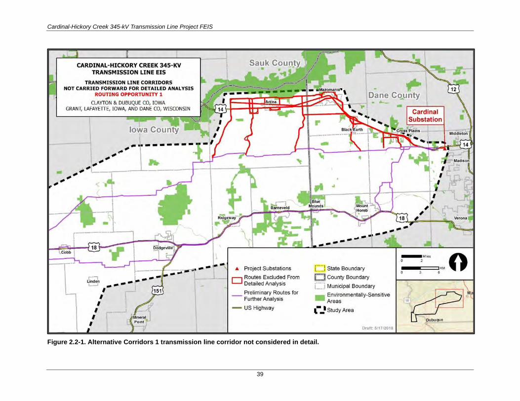
Cardinal-Hickory Creek 345-kV Transmission Line Project FEIS
39
Figure 2.2-1. Alternative Corridors 1 transmission line corridor not considered in detail.

Cardinal-Hickory Creek 345-kV Transmission Line Project FEIS
40
Figure 2.2-2. Alternative Corridors 2 transmission line corridor not considered in detail.
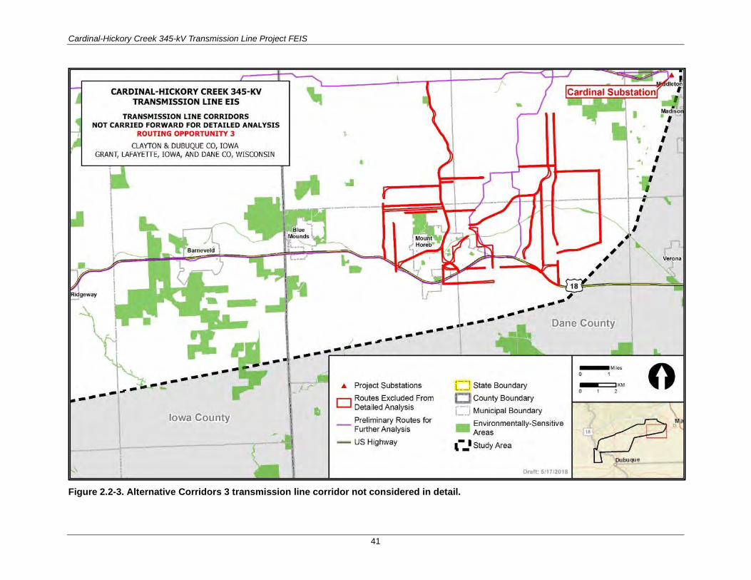
Cardinal-Hickory Creek 345-kV Transmission Line Project FEIS
41
Figure 2.2-3. Alternative Corridors 3 transmission line corridor not considered in detail.
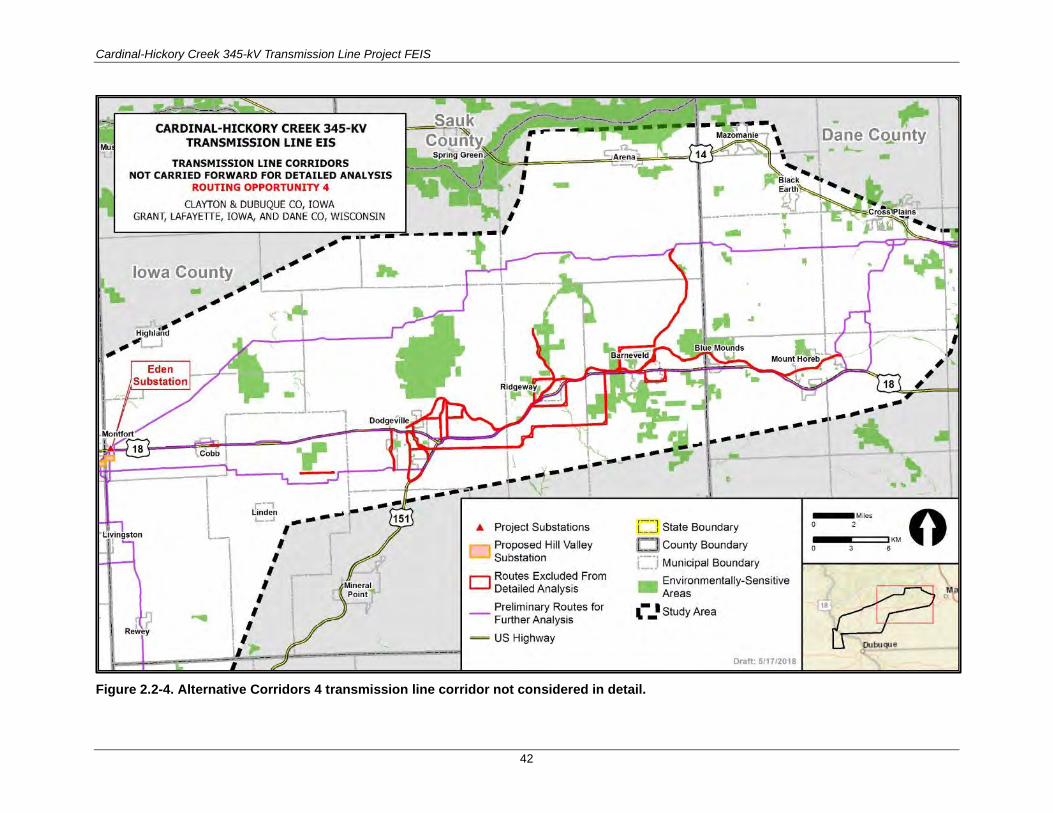
Cardinal-Hickory Creek 345-kV Transmission Line Project FEIS
42
Figure 2.2-4. Alternative Corridors 4 transmission line corridor not considered in detail.

Cardinal-Hickory Creek 345-kV Transmission Line Project FEIS
43
Figure 2.2-5. Alternative Corridors 5 transmission line corridor not considered in detail.

Cardinal-Hickory Creek 345-kV Transmission Line Project FEIS
44
2.2.1.1.2 HILL VALLEY SUBSTATION-TO-MISSISSIPPI RIVER STUDY AREA
Of the 12 alternative corridors, seven are within the Hill Valley Substation-to-Mississippi River Study Area. The corridors and the reasons for removing them from further detailed consideration are described below.
Alternative Corridors 6
As shown in Figure 2.2-6, this set of alternative corridors would occur west of Montfort, westward and southwest to Lancaster, and north of the proposed Northern Alternatives. Alternative Corridors 6 would follow an existing 69-kV transmission line ROW, a natural gas pipeline ROW, U.S. Routes 18 and 61, and State Highway 129. These corridors were removed from further consideration because of potential impacts to the community of Montfort and because an existing 138-kV transmission line ROW provides a straighter, shorter, and more direct route with fewer potential constraints.
Alternative Corridors 7
As shown in Figure 2.2-7, this set of alternative corridors would occur west of Alternative Corridors 6, around Lancaster, then west and southwest to Cassville, on the north side of the proposed Northern Alternatives. Alternative Corridors 7 would follow existing 161- and 69-kV transmission line ROWs; U.S. Route 61; State Highways 35, 81, and 133; and a new cross-country corridor. These corridors were removed from further consideration because of potential impacts to the community of Lancaster and because an existing 138-kV transmission line ROW provides a straighter, shorter, and more direct route with fewer potential constraints.
Alternative Corridors 8
As shown in Figure 2.2-8, these two alternative corridors would go through the eastern part of Livingston. Alternative Corridors 8 would follow an existing 69-kV transmission line ROW and State Highway 80. Portions of the utility and transportation ROWs were removed from further consideration because they went directly through the community of Livingston.
Alternative Corridors 9
As shown in Figure 2.2-9, these two alternative corridors would occur between Livingston and Platteville. One corridor would skirt around east of the Village of Rewey, and the second would be located west of the proposed Southern Alternatives from the western border of Livingston to northeast Platteville. Alternative Corridors 9 would follow State Highway 80 and a new cross-country corridor. These corridors were removed from further consideration because they were longer and less direct and could have a greater impact on residential areas than other options evaluated.
Alternative Corridors 10
As shown in Figure 2.2-10, this set of alternative corridors would occur between the proposed C-HC Project action alternatives, from east and southeast of Lancaster on the proposed Northern Alternatives, then east and southeast to connect with the proposed Southern Alternatives in the Platteville area. Alternative Corridors 10 would follow an existing 69-kV transmission line ROW, a natural gas pipeline ROW, State Highways 80 and 81, and a new cross-country corridor. These corridors were removed from further consideration because they did not sufficiently avoid residential developments, civic facilities, and environmental constraints associated with Platteville. Connector segments were also removed because they did not follow a path consistent with the southwesterly direction of the proposed C-HC Project.

Cardinal-Hickory Creek 345-kV Transmission Line Project FEIS
45
Alternative Corridors 11
As shown in Figure 2.2-11, this set of alternative corridors would occur west of Alternative Corridors 10, between the active Segments D and E, from west of Platteville and south of Lancaster, westward to just north of Cassville. Alternative Corridors 11 would follow an existing 69-kV transmission line ROW and connector segments along new cross-country corridors. These corridors were removed from further consideration because they were longer and could have greater potential impacts on residential developments and civic constraints, when compared with the 138-kV transmission line ROW to the south.
Alternative Corridors 12
As shown in Figure 2.2-12, this set of alternative corridors would occur north and northwest of Cassville and would provide various options for connecting to active Segments D and E. Alternative Corridors 12 would follow State Highways 133 and 81 and a railroad corridor. These corridors were removed from further consideration because of potential impacts to residential developments and civic constraints associated with the community of Cassville. In addition, geographic constraints, such as the existing railroad corridor and topography, would make them difficult to construct.

Cardinal-Hickory Creek 345-kV Transmission Line Project FEIS
46
Figure 2.2-6. Alternative Corridors 6 transmission line corridor not considered in detail.
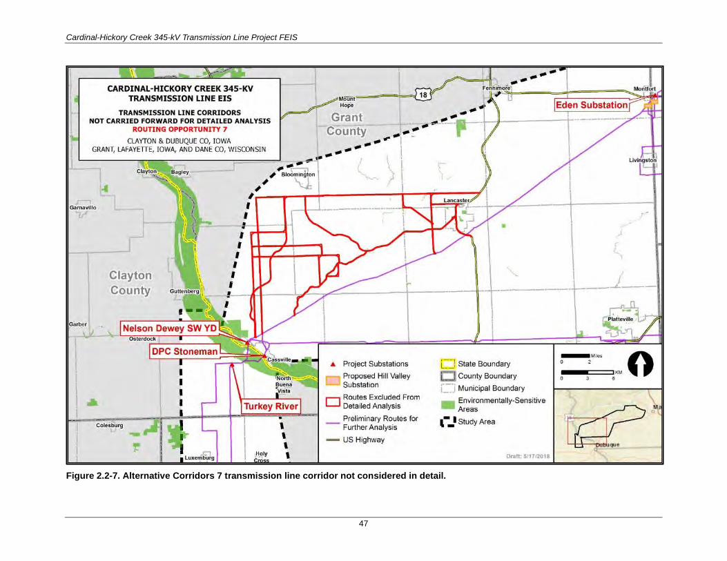
Cardinal-Hickory Creek 345-kV Transmission Line Project FEIS
47
Figure 2.2-7. Alternative Corridors 7 transmission line corridor not considered in detail.

Cardinal-Hickory Creek 345-kV Transmission Line Project FEIS
48
Figure 2.2-8. Alternative Corridors 8 transmission line corridor not considered in detail.
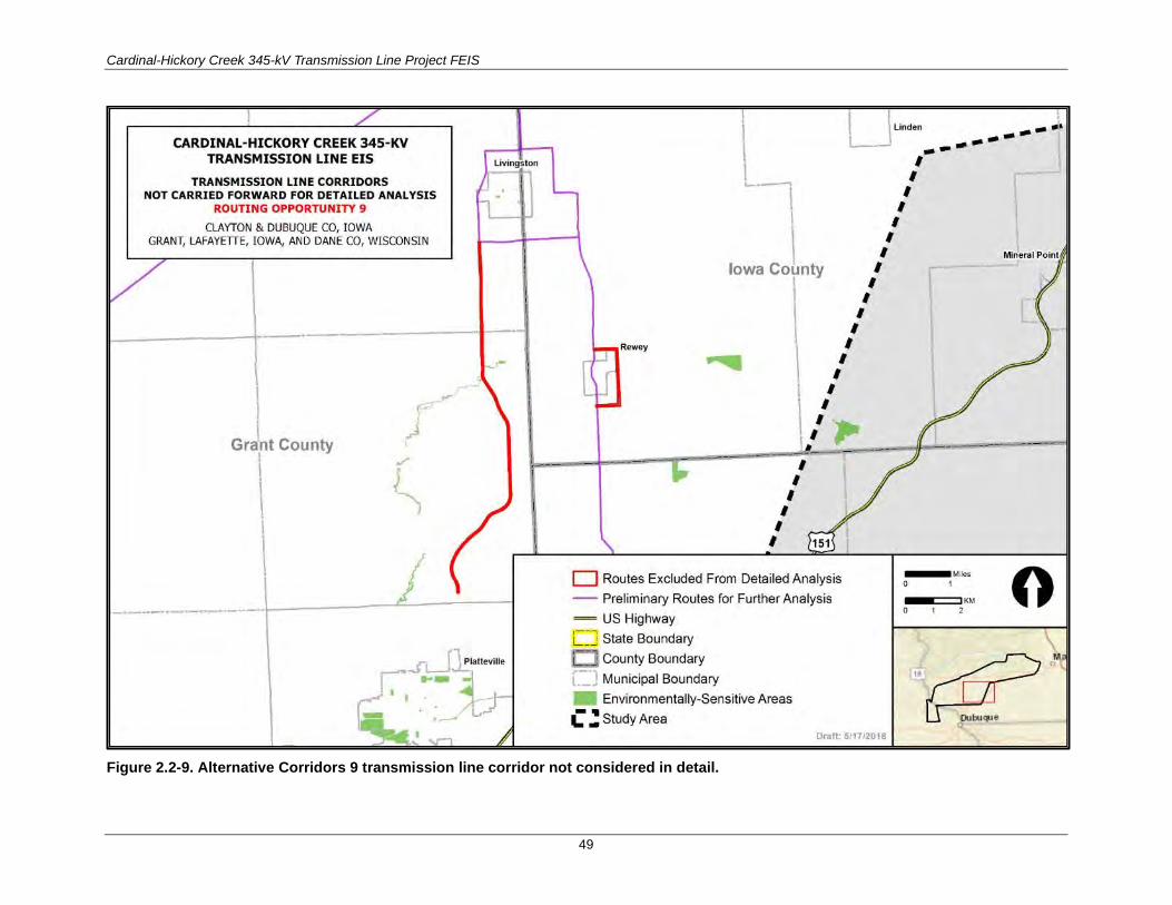
Cardinal-Hickory Creek 345-kV Transmission Line Project FEIS
49
Figure 2.2-9. Alternative Corridors 9 transmission line corridor not considered in detail.

Cardinal-Hickory Creek 345-kV Transmission Line Project FEIS
50
Figure 2.2-10. Alternative Corridors 10 transmission line corridor not considered in detail.

Cardinal-Hickory Creek 345-kV Transmission Line Project FEIS
51
Figure 2.2-11. Alternative Corridors 11 transmission line corridor not considered in detail.

Cardinal-Hickory Creek 345-kV Transmission Line Project FEIS
52
Figure 2.2-12. Alternative Corridors 12 transmission line corridor not considered in detail.
Cardinal-Hickory Creek 345-kV Transmission Line Project FEIS
53
2.2.1.2 Alternative Mississippi River Crossings During the siting analyses, five alternative corridors were identified and studied for crossing the Mississippi River but were dropped from detailed analyses (Burns and McDonnell 2016). These corridors are shown in Figure 2.2-13 and summarized in Table 2.2-2.
With rationale for dismissal from further consideration in this FEIS. The five alternative corridors for crossing the Mississippi River are:
• Lock and Dam No. 10 in Guttenberg, Iowa (L&D 10) • Lock and Dam No. 11 in Dubuque, Iowa (L&D 11) • Highway 61/151 crossing in Dubuque, Iowa (Highway 151 Bridge) • Julien Dubuque Bridge/Highway 20 crossing in Dubuque, Iowa (Julien Dubuque Bridge) • Dubuque to Galena 161-kV Transmission Line crossing in Dubuque, Iowa (Galena 161-kV
Transmission Line)
The Lock and Dam No. 10 river crossing was removed from further consideration because of potential impacts to archaeological and cultural resources within the city of Guttenberg, Iowa, no existing utility ROWs are located at or near the crossing location, the USACE identified technical/construction and safety issues that prohibited construction, and the alternative potential routes to this river crossing option would be the longest of any river crossing alternative due to its northernmost location.
The Lock and Dam No. 11 river crossing was removed from further consideration because of potential impacts to archaeological and cultural resources, visual resources, and residential development and because it would pass through downtown Dubuque; in addition, there are no existing overhead transmission line ROWs at or near this Mississippi River crossing, and the USACE identified technical and construction issues that prohibit construction.
The Highway 61/151 and Julien Dubuque Bridge/Highway 20 river crossings were removed from further consideration because of potential impacts to residential developments, technical issues during construction, and safety issues during operation and maintenance with highway traffic and infrastructure; in addition, there were no existing overhead transmission line ROWs accessing the crossing.
The Dubuque to Galena 161-kV Transmission Line river crossing was removed from further consideration because of potential impacts to residential developments and downtown Dubuque, as well as to parks and recreation.
In addition to the technical feasibility issues and potential impacts listed above, the City of Dubuque also passed a resolution, Resolution No. 215-15, on June 15, 2015, which states that an application for a transmission line license for the C-HC Project would not be permittable under the City’s Code of Ordinances and proceeding with the process required by Chapter 11-6 would not be in the public interest. The City of Dubuque has exclusive permitting authority over whether a transmission line of this voltage can be constructed within its jurisdictional boundary. Due to this resolution, the Utilities determined that routing the C-HC Project through the city of Dubuque was not feasible.
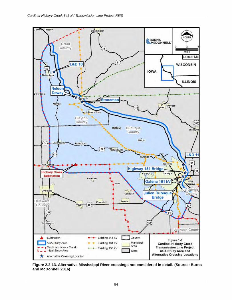
Cardinal-Hickory Creek 345-kV Transmission Line Project FEIS
54
Figure 2.2-13. Alternative Mississippi River crossings not considered in detail. (Source: Burns and McDonnell 2016)

Cardinal-Hickory Creek 345-kV Transmission Line Project FEIS
55
Table 2.2-2. Alternative Transmission Line Corridors Not Carried Forward for Detailed Analysis—Mississippi River Crossing
Corridor Description Reasons Removed from Detailed Analysis
Lock and Dam No. 10 in Guttenberg, Iowa (L&D 10)
• The City of Guttenberg, Iowa, has more than 350 recorded historic-aged resources including three NRHP districts and several individually listed NRHP properties (including Lock and Dam No. 10 itself). This potential Mississippi River crossing alternative for L&D 10 includes the presence of 196 historic structures within 1,000 feet of the proposed route alignment, the highest among all Mississippi River crossing alternatives. • No existing utility ROWs occur at or near the L&D 10 crossing or on the Wisconsin side of this crossing location; the Wisconsin side is primarily mature woodlands and agricultural fields. • Alternative Mississippi River crossing options immediately upstream and downstream of L&D 10 are limited by proximity to a private airfield to the north of L&D 10 and Goetz Island, Swift Slough, and Guttenberg Ponds Sanctuary within the Refuge to the south. • Safety and technical engineering considerations prohibit construction of transmission facilities on or near Lock and Dam No. 10, per USACE review. • The L&D 10 alternative route is the longest (25.6 miles) compared to all other potential Mississippi River crossing alternatives.
Lock and Dam No. 11 in Dubuque, Iowa (L&D 11)
• The crossing would require routing through urban residential development and downtown Dubuque. • The potential Mississippi River crossing alternative would cross numerous residential properties (58 homes would be within 100 feet of centerline of transmission line corridor, nine of which would be within 25 feet). • There are no existing overhead transmission corridors across the Mississippi River at or near Lock and Dam No. 11. • The crossing presents technical challenges; it would require a 3,200-foot crossing of the Mississippi River with projected structure heights of 250 to 300 feet with permanent lighting. • The C-HC Project would be visible from multiple viewpoint locations at Eagle Point Park. • Lock and Dam No. 11 is a listed site on the NRHP; there are visual/scenic considerations related to the NRHP listing. • Safety and technical engineering considerations prohibit construction of transmission facilities on or near Lock and Dam No. 11, per USACE review.
Highway 61/151 crossing in Dubuque, Iowa (Highway 151 Bridge)
• The City passed a resolution stating that the transmission line route for the C-HC Project would not be permittable. • The potential Mississippi River crossing alternative requires routing through urban residential development and downtown Dubuque. • Corridors to both locations would cross numerous residential properties (58 homes would be within 100 feet of centerline of transmission line corridor, nine of which would be within 25 feet). • Iowa Department of Transportation (Iowa DOT) would not be able to safely perform ongoing routine bridge maintenance while the transmission line is energized. As a result, the line would need to be de-energized during these maintenance activities, which would not allow for the reliable use of a transmission line at these locations and would not meet the purpose of and need for the C-HC Project. • Unresolvable engineering conflicts with bridge safety prohibit construction of transmission facilities on these bridges, per Iowa DOT review of the C-HC Project. • At these locations, the project would result in shutdown or disruption of traffic flow on major bridges between Iowa and Wisconsin/Illinois during construction and maintenance of the transmission line. • Neither bridge location has existing overhead transmission lines.

Cardinal-Hickory Creek 345-kV Transmission Line Project FEIS
56
Corridor Description Reasons Removed from Detailed Analysis
Julien Dubuque Bridge/Highway 20 crossing in Dubuque, Iowa (Julien Dubuque Bridge)
• The City passed a resolution stating that the transmission line route for the C-HC Project would not be permittable. • The potential Mississippi River crossing alternative requires routing through urban residential development and downtown Dubuque. • Corridors to both locations would cross numerous residential properties (58 homes would be within 100 feet of centerline of transmission line corridor; nine of these would be within 25 feet). • Iowa DOT would not be able to safely perform ongoing routine bridge maintenance while the transmission line is energized. As a result, the line would need to be de-energized during these maintenance activities, which would not allow for the reliable use of a transmission line at these locations and would not meet the purpose of and need for the C-HC Project. • Unresolvable engineering conflicts with bridge safety prohibit construction of transmission facilities on these bridges, per Iowa DOT review of the C-HC Project. • At these locations, the project would result in shutdown or disruption of traffic flow on major bridges between Iowa and Wisconsin/Illinois during construction and maintenance of the transmission line. • Neither bridge location has existing overhead transmission lines.
Dubuque to Galena 161-kV Transmission Line crossing in Dubuque, Iowa (Galena 161-kV Transmission Line)
• The City passed a resolution stating the transmission line route for the C-HC Project through Dubuque would not be permittable. • The potential Mississippi River crossing alternative requires routing through urban residential development and downtown Dubuque. • The corridor would cross numerous residential properties (61 homes would be within 100 feet of centerline of transmission line corridor, nine of which would be within 25 feet). • Requires routing new 345-kV line through Schmitt Island and Riverview Park; the new line would cross recreational fields for which Federal funds were obtained, the use of which may limit or prohibit redevelopment of these areas.
Source: Burns and McDonnell (2016)
2.2.1.3 Alternative Routes for Crossing the Refuge The Utilities began their route analysis for the C-HC Project by focusing on the crossing of the Mississippi River, as the location of this crossing would determine the potential C-HC Project routes in both Iowa and Wisconsin. The Utilities have been meeting with USFWS since April 2012 to discuss potential crossings, including crossings of the Refuge. If given a choice, the USFWS Refuge management would prefer a crossing not involving/affecting Refuge-managed lands, thus, at the request of the Refuge manager, the Utilities provided an Alternative Crossings Analysis report to demonstrate that non-Refuge options were infeasible. In the ACA report, the Utilities provided data and analyses supporting that non-Refuge alternatives were not economically or technically feasible and would have greater overall environmental and human impacts, compared with the feasible Refuge crossing locations (Burns and McDonnell 2016). Two alternatives for crossing the Mississippi River and the Refuge were identified as feasible: the Nelson Dewey river crossing and the Stoneman river crossing (Figure 2.2-14). In coordination with the USFWS and other stakeholders four segments were proposed for the alternative crossing the Refuge at the Nelson Dewy river crossing. Two of these segments have been dismissed from further consideration (see Figure 2.2-14). The first segment crossed a private inholding within the Refuge. This segment would minimize the acres of federally managed lands crossed by the C-HC Project within the Refuge. However, after discussions with the private inholding landowner in 2018, it was determined the landowner would not agree to an easement crossing the landowner’s land.

Cardinal-Hickory Creek 345-kV Transmission Line Project FEIS
57
Figure 2.2-14. Refuge segments dismissed from detailed analysis.

Cardinal-Hickory Creek 345-kV Transmission Line Project FEIS
58
The other segment would avoid the private inholding by paralleling Oak Road to the northwest of the inholding and would continue to follow Oak Road across the Refuge southwest to the railroad corridor along the south boundary of the Refuge. This segment would then parallel the railroad corridor, adjacent to the railroad ROW southeast until it entered the existing 161-kV transmission line ROW to exit the Refuge. This segment was dismissed from further consideration because it is longer than other options considered, and more disturbance within the Refuge would be associated with this segment. Furthermore, the two tight right angles needed for the transmission line to move from along Oak Road to the railroad corridor would require larger structures to ensure the transmission line was structurally engineered. In September 2018, the USFWS agreed to dismiss the option from detailed analysis.
The USFWS does not have a preferred alternative for crossing the Refuge; however, all segments that would cross the Refuge were developed in coordination with the USFWS, with the goal of reducing habitat fragmentation and resource impacts within the Refuge. The USFWS has received an application from the Utilities for a ROW permit. The route proposed in the ROW permit application has been evaluated through a Refuge compatibility determination (see Appendix J) which is available for public comment with the same comment deadline as this FEIS.
2.2.2 Non-Transmission, Lower-Voltage, and Underground Alternatives
Non-transmission alternatives reviewed for this FEIS include regional or local renewable electricity generation (i.e., solar), energy storage, energy efficiency, and demand response. These electricity generation and management options are briefly described below. In addition, RUS also considered two transmission line alternatives, a lower-voltage alternative and underground burial of the transmission line. These alternatives were not carried forward for detailed analysis; this section provides rationale for why these alternatives were not carried forward for detailed analysis.
As discussed in Chapter 1, the need for the Proposed Action considered in this FEIS is to increase the capacity of the regional transmission system to:
• address reliability issues on the regional bulk transmission system and ensure a stable and continuous supply of electricity is available to be delivered where it is needed even when facilities (e.g., transmission lines or generation resources) are out of service;
• alleviate congestion that occurs in certain parts of the transmission system and thereby remove constraints that limit the delivery of power from where it is generated to where it is needed to satisfy end-user demand;
• expand the access of the transmission system to additional resources including: 1) lower-cost generation from a larger and more competitive market that would reduce the overall cost of delivering electricity and 2) renewable energy generation needed to meet state renewable portfolio standards and goals and support the nation’s changing electricity mix;
• increase the transfer capability of the electrical system between Iowa and Wisconsin;
• reduce the losses in transferring power and increase the efficiency of the transmission system and thereby allow electricity to be moved across the grid and delivered to end-users more cost-effectively; and
• respond to public policy objectives aimed at enhancing the nation’s transmission system and to support the changing generation mix by gaining access to additional resources such as renewable energy or natural gas-fired generation facilities.

Cardinal-Hickory Creek 345-kV Transmission Line Project FEIS
59
The non-transmission, lower-voltage, and underground alternatives were evaluated based on the six-point need for the Proposed Action. Table 2.2-3 summarizes how these alternatives may or may not address the six-point need as well as other considerations for not carrying these alternatives forward for detailed analysis. FEIS Sections 2.2.2.1 through 2.2.2.6 provide a detailed explanation that expands upon the information presented in Table 2.2-3. Furthermore, these alternatives may not be pertinent to the applications to which the Federal agencies must respond.
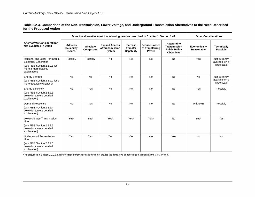
Cardinal-Hickory Creek 345-kV Transmission Line Project FEIS
60
Table 2.2-3. Comparison of the Non-Transmission, Lower-Voltage, and Underground Transmission Alternatives to the Need Described for the Proposed Action
Alternatives Considered but Not Evaluated in Detail
Does the alternative meet the following need as described in Chapter 1, Section 1.4? Other Considerations
Address Reliability
Issues Alleviate
Congestion Expand Access of Transmission
System
Increase Transfer
Capability
Reduce Losses of Transferring
Power
Respond to Transmission Public Policy
Objectives
Economically Reasonable
Technically Feasible
Regional and Local Renewable Electricity Generation (see FEIS Section 2.2.2.1 for more a more detailed explanation)
Possibly Possibly No No No No Yes Not currently available on a
large scale
Energy Storage (see FEIS Section 2.2.2.2 for a more detailed explanation)
No No No No No No No Not currently available on a
large scale
Energy Efficiency (see FEIS Section 2.2.2.3 below for a more detailed explanation)
No Yes No No No No Yes Possibly
Demand Response (see FEIS Section 2.2.2.4 below for a more detailed explanation)
No Yes No No No No Unknown Possibly
Lower-Voltage Transmission Line (see FEIS Section 2.2.2.5 below for a more detailed explanation)
Yes* Yes* Yes* Yes* Yes* No Yes* Yes
Underground Transmission Line (see FEIS Section 2.2.2.6 below for a more detailed explanation)
Yes Yes Yes Yes Yes Yes No No
* As discussed in Section 2.2.2.5, a lower-voltage transmission line would not provide the same level of benefits to the region as the C-HC Project.

Cardinal-Hickory Creek 345-kV Transmission Line Project FEIS
61
2.2.2.1 Regional and Local Renewable Electricity Generation Many comments received during public scoping suggested that RUS consider community-scale and residential photovoltaic solar projects as an alternative to constructing a 345-kV transmission line. Community solar could include options such as installing solar panels within existing substations or on other open land where such use has been approved. Residential solar refers to installing solar panels on individual homes, either on roofs or on ground-mounted structures. Photovoltaic solar power has the benefit of providing peak electrical generation during hot summer days, which coincides with part of the period of peak demand. However, peak load often extends into summer nights as well, when photovoltaic systems stop generating electricity. Thus, without sufficient power storage capacity, residential photovoltaic solar systems have limited usefulness in resolving the identified grid reliability deficiencies in the region.
Siting and construction of new photovoltaic solar facilities would take time, possibly including the time required for state regulatory review if several large facilities were sited on the Wisconsin side of the Mississippi River. Depending on where they were sited, additional or upgraded transmission line facilities might also be required to integrate this new generation into the electrical grid (PSCW 2011a).
An example of the amount of land area and the number of panels that are required to provide significant quantities of electricity using solar photovoltaic panels is provided by five 5-MW solar projects being proposed in the state of Washington (TUUSSO Energy 2018). Each of those 5-MW solar projects would occur on parcels ranging from 40 to 50 acres and would require installation of about 18,000 solar panels. As indicated in Chapter 1, the estimated needed increase in transfer capability in the region is approximately 1,200 MW, depending on the time of year, which would enable a number of new generators to interconnect as well. If the characteristics of the example solar project were scaled up to replace the 1,200 MW of transfer capability, it could mean that a minimum of 9,850 acres of land and 4.432 million panels would be required to satisfy the necessary transfer capability. As with wind power, physical obstructions and local laws might increase the area needed for this capability (PSCW 2011a).
Several solar photovoltaic technologies could be employed, at varying levels of cost and efficiency. Crystalline solar cells are more efficient at converting sunlight into electricity and could cost $2.50 to $6.00 per (direct current) watt or less. Thin-film solar cells are less efficient but would also cost less than crystalline cells (PSCW 2011a). Each of the five example solar projects described above is estimated to cost $8 to 10 million to construct (TUUSSO Energy 2018).
The average residential solar project, also known as rooftop solar, is 5 kilowatt (kW) (U.S. Energy Information Administration 2015). Approximately 246,000 residential solar projects would be required to replace the 1,200 to 1,300 MW needed capability in the region. For context, as of December 2017, approximately 85 MW of solar generating capacity has been installed in Wisconsin (RENEW Wisconsin 2017).
RUS recognizes the value of renewable energy to our nation’s changing energy mix; however regional and local renewable energy generation is not currently available at a scale to serve as a viable alternative to the Proposed Action contained within the applications to which the Federal agencies are responding, as described in Chapter 1. As cited in the PSCW’s Strategic Energy Assessment, customer-owned distributed energy resources (which includes biogas, fossil fuel, hydroelectric, landfill gas, solar photovoltaic, energy storage, and wind) is less than 1% of the total energy provided to Wisconsin customers (PSCW 2016). Furthermore, local and regional renewable energy generation does not meet the primary six-point need for the Proposed Action. Specifically, community and residential solar alternatives would not expand the access of the transmission system, reduce transmission losses, or respond to public

Cardinal-Hickory Creek 345-kV Transmission Line Project FEIS
62
policy objectives aimed at enhancing the nation’s transmission system. Therefore, the local and regional renewable energy generation alternative was dismissed from detailed analysis in this FEIS.
2.2.2.2 Energy Storage One of the C-HC Project’s purposes is to improve the transfer capability between Iowa and Wisconsin. Energy storage, such as the use of batteries, could increase electricity transfer capability by charging or discharging energy, depending on the storage location, when additional transfer capability is required. However, a tremendous amount of storage would be required to replace the increased transfer capability that would be provided the C-HC Project. That volume of storage could only be provided by pumped hydro, compressed air, or molten salt, none of which is available in Wisconsin due to the state’s geographic features (Dairyland et al. 2016a). To provide similar levels of transfer capability and the economic and reliability support of this project, multiple storage installations at a variety of locations would be necessary because a storage device must be recharged after each use and can only run for a certain number of hours before needing a recharge. Battery storage is not a technically feasible alternative at this time due to the large amount of storage capacity that would be required to match the beneficial impacts of the C-HC Project (Dairyland et al. 2016a). Widespread utility-scale energy storage projects by means of electric batteries are still too expensive to consider as a reasonable alternative to the C-HC Project (Dairyland et al. 2016a).
Energy storage is not an alternative that is pertinent to the applications to which the Federal agencies are responding, as described in Chapter 1. In addition, energy storage does not meet the primary six-point need for the Proposed Action, including addressing reliability issues at a scale commensurate with transmission, alleviating congestion, expanding access of the transmission system, reducing transmission losses, or responding to public policy objectives aimed at enhancing the nation’s transmission system. Therefore, the energy storage alternative was dismissed from detailed analysis in this FEIS.
2.2.2.3 Energy Efficiency Wisconsin continues to be a leader through its statewide energy efficiency program, Focus on Energy (PSCW 2016). Participation in energy efficiency programs is voluntary in Wisconsin (PSCW 2011a). MISO considered energy efficiency in all four of its futures modeling efforts and found that energy efficiency could not eliminate the need for the C-HC Project (Dairyland et al. 2016a). To replace this project with energy efficiency, energy-efficiency efforts would have to eliminate demand to a level that all the Renewable Portfolio Standards and Goals would be met with existing renewable resources and that the reliability and congestion benefits would be achieved through a dramatic reduction in flows on the regional grid. An increase in energy efficiency substantial enough to offset the need for the proposed C- HC Project would not be possible (Dairyland et al. 2016a). Implementing energy efficiency programs also would have to be monitored continuously to make sure that load levels do not increase to the point where they cause problems for the transmission system (PSCW 2011a).
Energy efficiency is not an alternative that is pertinent to the applications to which the Federal agencies are responding, as described in Chapter 1. In addition, energy efficiency does not meet the primary six-point need for the Proposed Action. Specifically, this alternative does not address reliability issues on the regional bulk transmission system at a scale commensurate with transmission, expand the access of the transmission system to additional resources, reduce the losses in transferring power, or respond to public policy objectives aimed at enhancing the nation’s transmission system and supporting the changing generation mix. Therefore, the energy efficiency alternative was dismissed from detailed analysis in this FEIS.

Cardinal-Hickory Creek 345-kV Transmission Line Project FEIS
63
2.2.2.4 Demand Response As with energy efficiency, demand response (also known as load reduction and load shifting) results in a decreased need for electricity. FERC defines demand response as “changes in electric use by demand-side resources [consumers] from their normal consumption patterns in response to changes in the price of electricity, or to incentive payments designed to induce lower electricity use at times of high wholesale market process or when system reliability is jeopardized” (FERC 2010). If load reduction were contracted to respond to real-time market signals, it could provide some congestion relief. However, the level of demand response needed to provide sufficient congestion relief to match the scope of the C-HC Project, is not known to currently exist.
The PSCW has previously noted that demand response programs rely on voluntary compliance by electricity users. For other transmission line projects that implement load reduction programs as an alternative to transmission lines, load management programs are monitored continuously to make sure that load levels do not increase to the point where they cause problems for the transmission system (PSCW 2011a).
The PSCW has noted that the Energy Efficiency and Customer-Sited Renewable Resource Potential in Wisconsin study completed by the Energy Center of Wisconsin (2009) suggests that peak demand could cost-effectively be reduced by 1.6% annually on a statewide basis, after a ramp-up period. If this level of reduction could be achieved in the C-HC Project area, peak demand growth could be negative. However, as indicated above, there is no regulatory authority to ensure energy user compliance with load reduction and energy efficiency goals and, thus, no mechanism has been identified that would ensure adequate participation over time (PSCW 2011a).
Demand response is not an alternative that is pertinent to the applications to which the Federal agencies are responding, as described in Chapter 1. Demand response does not meet the primary six-point need for the Proposed Action. Similar to energy efficiency, discussed above, this alternative does not address reliability issues on the regional bulk transmission system at a scale commensurate with transmission, expand the access of the transmission system to additional resources, reduce the losses in transferring power, or respond to public policy objectives aimed at enhancing the nation’s transmission system and supporting the changing generation mix. Therefore, the demand response alternative was dismissed from detailed analysis in this FEIS.
2.2.2.5 Lower-Voltage Transmission Line During the development of the MVP portfolio, MISO did consider whether portions of the portfolio could be lower voltage. In relation to the C-HC Project, MISO considered whether rebuilding the overloaded 138-kV lines between northeast Iowa and southwestern Wisconsin would be better than constructing a 345-kV line (MISO 2012b:29). MISO rejected this lower-voltage alternative because the estimated costs were greater than the C-HC Project, and it would not provide the same level of benefits (Dairyland et al. 2016a).
The development of MISO operating guides for multiple element outages highlights the need for a new high-voltage connection into southwestern Wisconsin. Under the lower-voltage alternative, multiple transmission line and associated facility improvements would be required to avoid loss of load in addition to any combination of lower-voltage lines. Additionally, a lower-voltage alternative would result in higher line losses than a 345-kV transmission line and would be less economically efficient (see Section 1.4.2.2 for an explanation of voltage and line losses).
Cardinal-Hickory Creek 345-kV Transmission Line Project FEIS
64
As discussed in Chapter 1, many wind developments in Iowa and Minnesota list the C-HC Project as a conditional project. While further study would be required, it is likely that the number of conditional projects would grow under any lower-voltage alternative. In other words, it is likely that, in addition to a lower-voltage alternative, additional transmission lines (new or rebuilt) would be required to convey wind from Iowa and Minnesota to the rest of the MISO area, including Wisconsin.
Furthermore, a lower-voltage alternative would provide less flexibility for supporting emerging public policy initiatives. Lower-voltage lines have lower ratings and higher impedances, which means less flexibility to accommodate new public policy requirements that rely on the ability to move large amounts of renewable energy from one geographic area to another.
The lower-voltage transmission line alternative does not meet the primary six-point need for the Proposed Action, including reducing transmission losses or responding to public policy objectives aimed at enhancing the nation’s transmission system. Based on these considerations, alternative voltages were dismissed for detailed analysis in this FEIS.
2.2.2.6 Underground Transmission Line Sometimes regulatory agencies and the public suggest that transmission lines be placed underground to reduce their visibility and to reduce or avoid other potential impacts. In comment letters dated September 6, 2018, and March 27, 2019, the NPS requested that RUS and C-HC Project Utilities consider the cost and feasibility of constructing portions of the transmission line underground in the vicinity of the Ice Age National Scenic Trail (NST) and Cross Plains Complex located near Cross Plains, Wisconsin, to avoid potential visual resource impacts to the trail and complex. This section addresses the request made in the NPS comment letter. The analysis contained in this section would also apply to other segments of the C-HC Project.
The transmission lines used for underground construction are highly complex, compared with overhead construction. There are two main types of underground transmission lines. One type is constructed in a conduit pipe with fluid or gas pumped or circulated through and around the cable to manage heat and insulate the cables. The other type is a solid dielectric cable, which requires no fluids or gas and is a more recent technological advancement (PSCW 2011b). Underground cables have different technical requirements than overhead lines and have different environmental impacts. Due to their different physical, environmental, and construction needs, underground transmission generally costs more and may be more complicated to construct than overhead lines.
The design and construction of underground transmission lines differ from overhead lines because of two significant technical challenges that need to be overcome: 1) providing sufficient insulation inside the conduit so that cables can be within inches of grounded material; and 2) dissipating the heat produced inside the conduit during the operation of the electrical cables (PSCW 2011b). Other design and construction elements also differ between underground transmission lines and overhead transmission lines, as discussed below.
Different types of underground transmission lines require different ancillary facilities. Some of these ancillary facilities are constructed underground, while others are aboveground and may have a significant footprint or structures visible at a distance. These facilities may include underground vaults, aboveground transition structures, transition stations, and pressurizing plants.
The trenching for the construction of underground lines causes greater overall disturbance to resources than overhead lines, which results in larger environmental impacts. Soil excavation and disturbance would be required to construct trenches along the entire ROW, rather than just at discrete structure

Cardinal-Hickory Creek 345-kV Transmission Line Project FEIS
65
locations. Most commonly, trenches are at least 6 to 8 feet deep to keep cables below the frost line (PSCW 2011b). When bedrock or subsoils consisting of large boulders are encountered, blasting may be required (PSCW 2011b). Overhead line construction disturbs resources mostly at the site of each transmission line structure. Trenching an underground line through farmlands, forests, wetlands, and other natural areas can cause significant land disturbances and impacts to environmental resources (PSCW 2011b). For example, when constructing an underground line through a sensitive area, there would likely be greater impacts from underground construction due to the trenching required, compared with overhead construction, where the sensitive area could either be spanned or structures would be constructed in discrete locations within the area. Depending on the depth to groundwater and whether the construction methods require the excavation to be dry, significant volumes of water may need to be managed. Where waterways cross the ROW, boring beneath the waterway would be required to install an underground line. Once a transmission line is installed underground, ongoing vegetation management would be needed to maintain the ROW free of woody vegetation and root systems.
Many engineering factors significantly increase the cost of underground transmission facilities. As the voltage increases, engineering constraints and costs dramatically increase. This is the reason why existing underground distribution lines typically include lower voltages (12–24 kV). In Wisconsin, there are approximately 12,000 miles of total transmission lines, including just over 100 miles of underground transmission lines. There are also no existing 345-kV underground segments in Wisconsin.
Costs for constructing underground transmission lines are determined by the local environment, the distances between splices and termination points, and the number of ancillary facilities required. Other costs consideration for underground transmission lines are ROW access, construction limitations in urban areas, conflicts with other utilities, trenching construction issues, crossing natural or human-made barriers, and the potential need for forced cooling facilities (PSCW 2011b).
Post-construction issues such as aesthetics, electric and magnetic fields, and property values are usually less of an issue for underground lines. Underground lines are not as visible after construction and tend to have less impact on property values and aesthetics than overhead lines. Underground transmission lines produce lower magnetic fields than aboveground lines because the underground conductors are placed closer together, which causes the magnetic fields created by each of the three conductors to cancel out some of the others’ fields. This results in reduced magnetic fields (PSCW 2011b).
Apart from cost and construction issues, there are continued maintenance and safety issues associated with the ROW of underground transmission lines. The ROW must be kept safe from accidental contact by subsequent construction activities. To protect individual lines against accidental future dig-ins, a concrete duct bank, a concrete slab, or patio blocks are installed above the line, along with a system of warning signs (HIGH-VOLTAGE BURIED CABLE). Additionally, if the lines are not constructed under roads or highways, the ROW must be kept clear of vegetation with long roots such as trees, which could interfere with the system (PSCW 2011b).
In 2011, the PSCW estimated that the general costs for constructing underground transmission lines range from 4 to 14 times more than the costs for overhead lines of the same voltage and same distance. For example, a typical new 69-kV overhead single-circuit transmission line costs approximately $285,000 per mile, compared with $1.5 million per mile for a new 69-kV underground line (without the terminals). A new 138-kV overhead line costs approximately $390,000 per mile, compared with $2 million per mile for underground (without the terminals) (PSCW 2011b).
To help inform a more project-specific cost estimate for constructing a portion of the C-HC Project underground, two reports were referenced:

Cardinal-Hickory Creek 345-kV Transmission Line Project FEIS
66
The CapX2020 345 kV Underground Report (CapX2020 report) prepared by Power Engineers, Inc. (Power Engineers Inc. 2010). Available at: http://www.capx2020.com/Projects/pdf/085-247_Xcel_CAPX2020_Underground%20Report_02-24-10_RevB.pdf
The Cardinal-Hickory Creek Transmission Line Project Alternative Crossings Analysis (ACA report; Burns and McDonnell 2016). Available at: https://www.rd.usda.gov/publications/environmental-studies/impact-statements/cardinal-%E2%80%93-hickory-creek-transmission-line. Accessed March 15, 2017.
The CapX2020 report presents a theoretical 2-mile segment of transmission line and analyzes two potentially viable options for constructing a 345-kV transmission line underground. Although the report is helpful in estimating the costs for underground transmission line construction, the limitations and assumptions within the report may not apply to the C-HC Project. Based on design, engineering, and construction information related to the equipment, materials, and methods used (at the time) to construct a 345-kV transmission line underground, the report estimated between $41.45 million and $45.55 million per mile in 2010 dollars for underground construction (Power Engineers, Inc. 2010).
The ACA report was prepared specifically for the segments of the C-HC Project that would cross the Mississippi River and the Refuge. The ACA report analyzed proposed alternative segments of transmission line against 38 criteria, including engineering considerations, environmental issues, and potential social impacts that provide a basis for pricing out the cost to construct the Mississippi River and Refuge segments underground. It is important to note that the segments analyzed in the ACA would include more technically advanced engineering and construction methods and would affect environmental resources to a higher degree than would be necessary for undergrounding at the NPS Ice Age NST and Cross Plains Complex. Depending on the results of the 38 variables analyzed in the report, the ACA report estimated costs for constructing the 345-kV transmission line underground between $40.4 million and $42.2 million per mile in 2016 dollars.
Understanding that the cost estimates provided in the two reports would not translate directly to the affected environment of the NPS Ice Age NST and Cross Plains Complex (the CapX2020 costs would likely escalate and the ACA costs would likely decrease), a rough order of magnitude of $40 million per mile was determined to be a reasonable cost estimate for underground construction in the vicinity of the Ice Age NST and Cross Plains Complex.
For the C-HC Project, the Utilities estimate that the proposed new 345-kV transmission line in the vicinity of the NPS Ice Age NST and Cross Plains Complex would cost between $4.5 million and $5 million per mile to construct overhead. Additionally, the Utilities estimate that roughly 11.4 contiguous miles of transmission line would need to be constructed underground in the vicinity of the NPS Ice Age NST in order to avoid visual impacts that would be observed from key observation points associated with the trail and Cross Plains Complex. This mileage estimate is informed by viewshed analysis conducted specifically for the key observation points associated with the NST and Complex, as discussed in detail in Section 3.11, and also includes reasonable engineering considerations that would avoid alternating segments of aboveground and underground transmission line construction within the 11.4-mile segment. In other words, the 11.4-mile segment is not entirely visible from all NST key observation points; however this length does encompass all NST key observation points. Therefore, in order to avoid visual resource impacts along 11.4 miles of transmission line with underground construction of the C-HC Project, the associated rough cost estimate would be on the order of $456 million ($40 million over 11.4 miles), compared with $51.3 million to $56.5 million for overhead construction of the same length.
Additionally, repair costs for an underground line are usually greater than costs for an equivalent overhead line. Leaks can cost $50,000 to $100,000 to locate and repair. A leak detection system for a

Cardinal-Hickory Creek 345-kV Transmission Line Project FEIS
67
cable system can cost from $1,000 to $400,000 to purchase and install, depending on the system technology. Molded joints for splices in certain types of underground transmission line could cost about $20,000 to repair. Field-made splices could cost up to $60,000 to repair (PSCW 2011b). Easement agreements may require the utility to compensate property owners for disruption in their property use and for property damage that is caused by repairing underground transmission lines on private property. Underground transmission lines have higher life-cycle costs than overhead transmission lines when combining the costs of construction, repair, and maintenance over the life of the line.
RUS received several public comments during the DEIS public review period suggesting that the proposed SOO Green Renewable Rail project (http://www.soogreenrr.com/) demonstrates a viable construction alternative to the proposed overhead construction for the C-HC Project. RUS investigated the status of the SOO Green Renewable Rail project and concluded the project was too conceptual and early in the pre-design phase to be deemed a reliable project example to inform alternatives for the C-HC Project.
The method to construct transmission lines underground is not in conflict with the primary six-point need for the Proposed Action; however, this construction method could be significantly more impacting to resources and much more expensive (estimated to be approximately 8 times more costly) than overhead construction of the C-HC Project. In addition, there are operational limitations and maintenance issues that must be weighed against the advantages. Based on these considerations, the method of constructing underground transmission lines was dismissed from detailed analysis in this FEIS.
2.3 DESCRIPTION OF ALTERNATIVES
2.3.1 No Action Alternative The No Action Alternative “provides a benchmark, enabling decision makers to compare the magnitude of environmental effects of the action alternatives” (CEQ 1981:Question 3) (40 CFR 1502.14). The No Action Alternative provides the environmental baseline against which the other alternatives are compared (RUS regulation 7 CFR 1970.6 (a)).
Under the No Action Alternative, RUS would not provide funding for Dairyland’s portion of the C-HC Project, and the USFWS and USACE would not grant the ROWs or regulatory permits necessary for the C-HC Project to cross the Refuge. The project would not be built, and existing land uses and present activities in the analysis area would continue.
As discussed in detail in Chapter 1, the wind generation currently developed, under construction, or proposed for Iowa would not be adequately served with increased transmission capacity to population centers in the east under the No Action Alternative. There are a number of wind generation projects in MISO that are dependent upon completion of the C-HC Project (see Table 1.4-2).
Also under the No Action Alternative, operating guides would need to stay in place to address the risk of cascading outages in southwestern and southcentral Wisconsin. Finally, other transmission system improvements listed in Table 2.4-1 would likely be needed in the future.
2.3.2 Alternative Transmission Line Routes The C-HC Project area, as described from east to west, would begin at the Cardinal Substation in the town of Middleton, in Dane County, Wisconsin. The transmission line would cross Iowa County and connect to a new Hill Valley Substation near the village of Montfort, Wisconsin. Depending on the selected alternatives, the new substation would be built in either Grant County or Iowa County, Wisconsin.

Cardinal-Hickory Creek 345-kV Transmission Line Project FEIS
68
The transmission line would then exit the substation, cross Grant County, and cross the Mississippi River near Cassville, Wisconsin. There are two potential Mississippi River crossing alternatives near Cassville. The river crossing would include two 345-kV double-circuited lines, one operated at 345 kV and the other at 161 kV. The 345-kV transmission line would terminate at the existing Hickory Creek Substation in northwest Dubuque County, Iowa. The line operated at 161 kV would connect to the Turkey River Substation in eastern Clayton County, Iowa. Where the proposed project would cross the Mississippi River, the ROW would occur within the Refuge, managed by both the USFWS and USACE. All other portions of the project area would cross private land.
The Utilities propose to construct a new approximately 100- to 125-mile 345-kV transmission line between Dane County, Wisconsin, and Dubuque County, Iowa. The proposed project includes the following facilities:
• At the existing Cardinal Substation in Dane County, Wisconsin: a new 345-kV terminal within the substation;
• At the proposed Hill Valley Substation near the village of Montfort, Wisconsin: an approximately 22-acre facility with five 345-kV circuit breakers, one 345-kV shunt reactor, one 345/138-kV autotransformer, and three 138-kV circuit breakers;
• At the existing Eden Substation near the village of Montfort, Wisconsin: transmission line protective relaying upgrades to be compatible with the new protective relays installed at the new Hill Valley Substation and replacement of conductors and switches to meet Utilities’ operating limits;
• Between the existing Eden Substation and the proposed Hill Valley Substation near the village of Montfort, Wisconsin: a rebuild of the approximately 1 mile of Hill Valley to Eden 138-kV transmission line;
• At the existing Wyoming Valley Substation near Wyoming, Wisconsin: installation of nine 16-foot ground rods to mitigate potential fault current contributions from the C-HC Project;
• Between the existing Cardinal Substation and the proposed Hill Valley Substation: a new 50- to 53-mile (depending on the final route) 345-kV transmission line;
• Between the proposed Hill Valley Substation and existing Hickory Creek Substation: a new 50- to 70-mile (depending on the final route) 345-kV transmission line;
• At the Mississippi River in Cassville, Wisconsin: a rebuild and possible relocation of the existing Mississippi River transmission line crossing to accommodate the new 345-kV transmission line and Dairyland’s 161-kV transmission line, and which would be capable of operating at 345/345-kV but would initially be operated at 345/161-kV; o depending on the final route and the Mississippi River crossing locations:
• a new 161-kV terminal and transmission line protective relaying upgrades within the existing Nelson Dewey Substation in Cassville, Wisconsin;
• a replaced or reinforced structure within the Stoneman Substation in Cassville, Wisconsin;
• Multiple, partial, or complete rebuilds of existing 69-kV, 138-kV, and 161-kV transmission lines in Wisconsin that would be collocated with the new 345-kV line;
• At the existing Turkey River Substation in Clayton County, Iowa: one new 161-/69-kV transformer, three new 161-kV circuit breakers, and four new 69-kV circuit breakers; and
Cardinal-Hickory Creek 345-kV Transmission Line Project FEIS
69
• At the existing Hickory Creek Substation in Dubuque County, Iowa: a new 345-kV terminal within the existing Hickory Creek Substation.
The estimated total cost for the proposed C-HC Project would range from $500 million to $550 million (in 2023 dollars), depending on the alternative selected. Dairyland intends to request financial assistance from RUS to fund its anticipated 9% ownership interest in the C-HC Project. If approved, the in-service date would be scheduled for 2023.
RUS has identified six alternatives for the C-HC Project. These alternatives consist of individual route segments that, when combined, form complete route alternatives connecting the Cardinal Substation in Wisconsin with the Hickory Creek Substation in Iowa (Figure 2.3-1). Figure 2.3-2 through Figure 2.3-13 show the alternative routes and Hill Valley Substation alternatives. Each alternative route segment is defined as a 150-foot-wide ROW in Wisconsin and a 200-foot-wide ROW in Iowa, within a larger 300- foot-wide analysis area. As the project continues to be developed, conditions would be identified or encountered during survey, engineering, ROW acquisition, and construction that may necessitate the Utilities to make adjustments within the larger 300-foot-wide corridor. These adjustments would address specific localized conditions, circumstances, and landowner requests not readily apparent as part of the route development and environmental review processes. Such adjustments would not be anticipated to result in substantial (if any) additional or different impacts. Any adjustments would generally be intended to reduce overall environmental impacts, to reduce project inconvenience to landowners, or to protect public safety.
Appendix C provides additional details regarding each segment considered in this FEIS as well as the complete route alternatives presented below.
Following the presentation of the six complete action alternatives for the C-HC Project, is a discussion of how these six alternatives would cross the Refuge (see Section 2.3.2.7).

Cardinal-Hickory Creek 345-kV Transmission Line Project FEIS
70
Figure 2.3-1. Transmission line alternative corridor segments map.
Cardinal-Hickory Creek 345-kV Transmission Line Project FEIS
71
2.3.2.1 Alternative 1: North Corridor Baseline Alternative 1 would include approximately 99 miles of transmission line, composed of the segments listed in Appendix C, Table C-4. Approximately 65 miles would be collocated with existing ROWs for transmission lines, railroads, and roadways. In places where the proposed transmission line is collocated with existing transmission lines, the lines would be installed with a double-circuit configuration on new transmission line structures, and the existing transmission line ROW would be used to accommodate the new structures. The typical ROW would be 150 feet wide in Wisconsin and 200 feet wide in Iowa, based on design standards used by the Utilities in each state. However, in exceptional circumstances, the ROW would differ from the typical widths. For example, one pinch-point location requires a 70-foot ROW, while the Refuge would have a 260-foot-wide ROW. Approximately 34 miles of transmission line would occur in new ROW.
Starting on the east end of Alternative 1 at the Cardinal Substation, Segments Y and W would follow the existing 69-kV transmission line to Segment P. Segment P would be a section of new transmission line ROW located along the northern half of the C-HC Study Area. Segment P would then connect with Segment N before connecting to the new Hill Valley Substation near Montfort, Wisconsin. Although either Substation Alternative S1 or S2 could be used, it is assumed that Substation Alternative S1 would be constructed for Alternative 1 (see Figure 2.3-3). Segments D and A would then connect the new Hill Valley Substation with the property containing the Nelson Dewey Substation, just northwest of Cassville, Wisconsin. The line would not connect into, but would bypass, the Nelson Dewey Substation.
Once the C-HC Project transmission line exits southward from the Nelson Dewey Substation property, it would cross the Mississippi River using the remainder of Segment A and Segment B-IA to connect with Segment A-IA which terminates at the Hickory Creek Substation in Dubuque County, Iowa. Under this alternative, the existing 161-/69-kV double-circuit configuration at the existing Stoneman Substation Mississippi River crossing would be removed and would require a modification of the physical structure of the Stoneman Substation. Under this alternative, the existing ROW for the 161-kV line within the Refuge would be revegetated following the requirements of USFWS and USACE.

Cardinal-Hickory Creek 345-kV Transmission Line Project FEIS
72
Figure 2.3-2. Alternative 1 transmission line corridor map.

Cardinal-Hickory Creek 345-kV Transmission Line Project FEIS
73
Figure 2.3-3. Alternative 1 Hill Valley Substation map.

Cardinal-Hickory Creek 345-kV Transmission Line Project FEIS
74
2.3.2.2 Alternative 2: North Corridor with Southern Variation Alternative 2 would include approximately 105 miles of transmission line, composed of the segments listed in Appendix C, Table C-5. Approximately 68 miles would be collocated with existing ROWs for transmission lines, railroads, and roadways. In places where the proposed transmission line is collocated with existing transmission lines, the lines would be installed with a double-circuit configuration on new transmission line structures, and the existing transmission line ROW would be used to accommodate the new structures. The typical ROW would be 150 feet wide in Wisconsin and 200 feet wide in Iowa, based on design standards used by the Utilities in each state. However, in exceptional circumstances, the ROW would differ from the typical widths. For example, one pinch-point location requires a 70-foot ROW, while the Refuge would have a 260-foot-wide ROW. Approximately 37 miles of transmission line would occur in new ROW.
Alternative 2 would follow much of the same route as Alternative 1. It would leave the Cardinal Substation following Segments Z, Y, X, P, and O; through the new Hill Valley Substation Alternative 2 (see Figure 2.3-5). The alternative would then follow Segment D before reaching the Mississippi River, where it would cross southeast on Segment C; and then follow part of Segment B and enter the property containing the Stoneman Substation but would not connect to that substation. Alternative 2 would then exit south of the Stoneman Substation property and cross the Mississippi River on the remainder of Segment B; and then follow Segment C-IA and western Segment D-IA into the Hickory Creek Substation.

Cardinal-Hickory Creek 345-kV Transmission Line Project FEIS
75
Figure 2.3-4. Alternative 2 transmission line corridor map.

Cardinal-Hickory Creek 345-kV Transmission Line Project FEIS
76
Figure 2.3-5. Alternative 2 Hill Valley Substation map.
Cardinal-Hickory Creek 345-kV Transmission Line Project FEIS
77
2.3.2.3 Alternative 3: North–South Crossover Corridor Alternative 3 would include approximately 117 miles of transmission line, composed of the segments listed in Appendix C, Table C-6. Approximately 79 miles would be collocated with existing ROWs for transmission lines, railroads, and roadways. In places where the proposed transmission line is collocated with existing transmission lines, the lines would be installed with a double-circuit configuration on new transmission line structures, and the existing transmission line ROW would be used to accommodate the new structures. The typical ROW would be 150 feet wide in Wisconsin and 200 feet wide in Iowa, based on design standards used by the Utilities in each state. However, in exceptional circumstances, the ROW would differ from the typical widths. For example, one pinch-point location requires a 70-foot ROW, while the Refuge would have a 260-foot-wide ROW. Approximately 38 miles of transmission line would occur in new ROW.
Alternative 3 also would initially follow Alternative 1 along Segments Y, W, P, and O. The alternative uses the new Hill Valley Substation Alternative 2, although either substation location is feasible (see Figure 2.3-7). The alternative would generally exit south out of the Hill Valley Substation and follow Segments M and K south. North of Livingston, the alternative would follow Segment I on the east side of the town; then south again on Segment H, then traverse west on Segments G, F, and E; then turn south to follow Segment B and enter the property containing the Stoneman Substation in Cassville, Wisconsin, but would not connect to that substation. The alternative would cross the Mississippi River on the remainder of Segment B, and then follow the eastern Segments C-IA and A-IA into the Hickory Creek Substation.

Cardinal-Hickory Creek 345-kV Transmission Line Project FEIS
78
Figure 2.3-6. Alternative 3 transmission line corridor map.

Cardinal-Hickory Creek 345-kV Transmission Line Project FEIS
79
Figure 2.3-7. Alternative 3 Hill Valley Substation map.

Cardinal-Hickory Creek 345-kV Transmission Line Project FEIS
80
2.3.2.4 Alternative 4: South Baseline Corridor Alternative 4 would include approximately 119 miles of transmission line, composed of the segments listed in Appendix C, Table C-7. Approximately 109 miles would be collocated with existing ROWs for transmission lines, railroads, and roadways. In places where the proposed transmission line is collocated with existing transmission lines, the lines would be installed with a double-circuit configuration on new transmission line structures, and the existing transmission line ROW would be used to accommodate the new structures. The typical ROW would be 150 feet wide in Wisconsin and 200 feet wide in Iowa, based on design standards used by the Utilities in each state. However, in exceptional circumstances, the ROW would differ from the typical widths. For example, one pinch-point location requires a 70-foot ROW, while the Refuge would have a 260-foot-wide ROW. Approximately 10 miles of transmission line would occur in new ROW.
Alternative 4 would leave the Cardinal Substation and traverse westerly on Segments Y and W. Just south of Cross Plains it would generally traverse south along Segments V and T until it passes just east of Mount Horeb. Alternative 4 would then follow U.S. Route 18 along Segment S, until it reaches and then passes on the north side of Dodgeville and traverses west on Segments Q and N; then follows Segment O south into the new Hill Valley Substation Alternative 2 (see Figure 2.3-9).
After leaving the substation, the transmission line would go south on Segments M and K; then just north of Livingston it would follow Segment I on the east side of the town; then south again on Segment H, then traverse west on Segments G, F, and E; then turn south to follow Segment B and to the Stoneman Substation; cross the Mississippi River on the remainder of Segment B, and then follow the eastern Segments C-IA and A-IA into the Hickory Creek Substation.

Cardinal-Hickory Creek 345-kV Transmission Line Project FEIS
81
Figure 2.3-8. Alternative 4 transmission line corridor map.

Cardinal-Hickory Creek 345-kV Transmission Line Project FEIS
82
Figure 2.3-9. Alternative 4 Hill Valley Substation map.

Cardinal-Hickory Creek 345-kV Transmission Line Project FEIS
83
2.3.2.5 Alternative 5: South Alternative Corridor Alternative 5 would include approximately 128 miles of transmission line, composed of the segments listed in Appendix C, Table C-8. Approximately 117 miles would be collocated with existing ROWs for transmission lines, railroads, and roadways. In places where the proposed transmission line is collocated with existing transmission lines, the lines would be installed with a double-circuit configuration on new transmission line structures, and the existing transmission line ROW would be used to accommodate the new structures. The typical ROW would be 150 feet wide in Wisconsin and 200 feet wide in Iowa, based on design standards used by the Utilities in each state. However, in exceptional circumstances, the ROW would differ from the typical widths. For example, one pinch-point location requires a 70-foot ROW, while the Refuge would have a 260-foot-wide ROW. Approximately 10 miles of transmission line would occur in new ROW.
Alternative 5 would follow much of the same route as Alternative 4, with a few adjustments. It would initially leave the Cardinal Substation and traverse westerly on Segments Y and W. Just south of Cross Plains it would generally traverse south along Segments V and U until it passed just west of Klevenville. The alternative would then pass just south of Mount Horeb, heading southwest along U.S. Route 18 and along Segment S, then would diverge just east of Dodgeville and follow Segment R south of Dodgeville. The alternative would turn west again, traversing north on Segment L to enter the new Hill Valley Substation Alternative 1 (see Figure 2.3-11).
After leaving the substation, the transmission line would go south on Segments L and K, then just north of Livingston it would follow Segment J to go around the west side of the town; then south again on Segment H, then would traverse west on Segments G, F, E, and C; then would turn south to the Nelson Dewey Substation. The transmission line would not connect into, but would bypass, the Nelson Dewey Substation.
After leaving the Nelson Dewey Substation property, the alternative would turn south on Segment A, and then would follow Segment B-IA and the western Segment D-IA into the Hickory Creek Substation. Under this alternative, the existing 161-/69-kV double-circuit configuration at the existing Stoneman Substation Mississippi River crossing would be removed and would require a modification of the physical structure of the Stoneman Substation. Under this alternative, the existing ROW for the 161-kV line within the Refuge would be revegetated following the requirements of USFWS and USACE.

Cardinal-Hickory Creek 345-kV Transmission Line Project FEIS
84
Figure 2.3-10. Alternative 5 transmission line corridor map.

Cardinal-Hickory Creek 345-kV Transmission Line Project FEIS
85
Figure 2.3-11. Alternative 5 Hill Valley Substation map.
Cardinal-Hickory Creek 345-kV Transmission Line Project FEIS
86
2.3.2.6 Alternative 6: South–North Crossover Corridor Alternative 6 would include approximately 101 miles of transmission line, composed of the segments listed in Appendix C, Table C-9. Minor adjustments were made to Alternative 6 between the DEIS and FEIS for consistency with the C-HC Project route in Wisconsin ordered by the PSCW on September 26, 2019. Adjustments include:
• Exchange of Segment X in place of Segment W and part of Segment V near the intersection of Stagecoach Road and County Road P south of Cross Plains, Wisconsin.
• Potential combined use of Segments S10B, S10C, S11B, and S11C along U.S. Highway 151 west of Barneveld, Wisconsin, to allow for ongoing discussions between the Utilities and the Wisconsin Department of Transportation.
• Accommodation of routing on either the north or south side of Wisconsin State Road 80 for approximately 1.5 miles along Segment Q02 east of Montfort, Wisconsin.
Approximately 97 miles would be collocated with existing ROWs for transmission lines, railroads, and roadways. In places where the proposed transmission line is collocated with existing transmission lines, the lines would be installed with a double-circuit configuration on new transmission line structures, and the existing transmission line ROW would be used to accommodate the new structures. The typical ROW would be 150 feet wide in Wisconsin and 200 feet wide in Iowa, based on design standards used by the Utilities in each state. However, in exceptional circumstances, the ROW would differ from the typical widths. For example, one pinch-point location requires a 70-foot ROW, while the Refuge would have a 260-foot-wide ROW. Approximately 4 miles of transmission line would occur in new ROW.
Alternative 6 would initially follow the southernmost route from the Cardinal Substation, using Segments Z, Y, and X. Just south of Cross Plains it would generally traverse south along Segments V and T until it passes just east of Mount Horeb. The alternative then turns southwest along U.S. Route 18 and along Segment S, until it reaches and then passes on the north side of Dodgeville and traverses west on Segments Q and N into the new Hill Valley Substation Alternative 1 (see Figure 2.3-13).
Once leaving the Hill Valley Substation, the route would cross into the southern portion of the Alternative 1 route. It would follow a portion of Segment L before then following Segments D and A to the Nelson Dewey Substation property, just northwest of Cassville, Wisconsin. The transmission line would not connect into, but would bypass, the Nelson Dewey Substation.
Once the transmission line exits southward from the Nelson Dewey Substation property, it would cross the Mississippi River using the remainder of Segment A and Segment B-IA, and generally traverse south on Segment A-IA to terminate at the Hickory Creek Substation in Clayton County, Iowa. Under this alternative, the existing 161-/69-kV double-circuit configuration at the existing Stoneman Substation Mississippi River crossing would be removed, which would also result in a modification of the physical structure of the Stoneman Substation. Under this alternative, the existing ROW for the 161-kV line within the Refuge would be revegetated following the requirements of USFWS and USACE.

Cardinal-Hickory Creek 345-kV Transmission Line Project FEIS
87
Figure 2.3-12. Alternative 6 transmission line corridor map.

Cardinal-Hickory Creek 345-kV Transmission Line Project FEIS
88
Figure 2.3-13. Alternative 6 Hill Valley Substation map.
Cardinal-Hickory Creek 345-kV Transmission Line Project FEIS
89
2.3.2.7 Alternatives within the Refuge All action alternatives would cross the Refuge. There are three different options for crossing the Refuge that were carried forward for detailed analysis, as described below and shown in Figure 2.3-14. Alternatives B-IA1 and B-IA2 are associated with the Nelson Dewey Mississippi River crossing, while Alternative C-IA is associated with the Stoneman Mississippi River crossing (Table 2.3-1). The ROW width for all alternatives within the Refuge would be 260 feet wide to accommodate the low-profile H- frame structures. USFWS does not have a preferred alternative for crossing the Refuge, however, all segments that would cross the Refuge were developed in coordination with the USFWS, with the goal of reducing habitat fragmentation and resource impacts within the Refuge. USFWS has received an application from the Utilities for a ROW permit. The route proposed in the ROW permit application has been evaluated through a Refuge compatibility determination (see Appendix J) which is available for public comment with the same comment deadline as this FEIS.
2.3.2.7.1 SEGMENT B-IA1
Segment B-IA1 would connect with Segment A in Wisconsin and Segment A-IA or D-IA in Iowa. Starting at the Mississippi River, Segment B-IA1 would generally follow Oak Road from the Turkey River landing for approximately 4,800 feet (0.9 mile), and then it would head southeast to connect with the existing 161-kV transmission line ROW (see Figure 2.3-14). Then, the transmission line would head southwest to climb the bluff and cross the Canadian Pacific railroad tracks and 360th Street along the southern boundary of the Refuge. Segment B-IA1 would continue west to the vicinity of the Turkey River Substation, as shown in Figure 2.3-14. In total, Segment B-IA1 would be 6,597 feet (1.2 mile) long, and the ROW would cover 39 acres (see Table 2.3-1).
2.3.2.7.2 SEGMENT B-IA2
Segment B-IA2 would connect with Segment A in Wisconsin and Segment A-IA or D-IA in Iowa. Starting at the Mississippi River, Segment B-IA2 would generally follow Oak Road from the Turkey River landing for approximately 5,200 feet (1 mile), and then it would head southwest before running parallel to the Canadian Pacific railroad tracks (see Figure 2.3-14). Along the railroad tracks, the C-HC Project would not overlap the railroad ROW due to safety requirements. The C-HC Project would also overlap with the existing 69-kV transmission line ROW, also referred to as the N-9 transmission line, for approximately 200 feet. Then, the C-HC Project would head southwest to climb the bluff and cross the Canadian Pacific railroad and 360th Street along the southern boundary of the Refuge. Segment B-IA2 would continue west to the vicinity of the Turkey River Substation, as shown in Figure 2.3-14. In total, Segment B-IA2 would be 7,408 feet (1.4 mile) long, and the ROW would cover 44 acres (see Table 2.3-1).
2.3.2.7.3 SEGMENT C-IA
Segment C-IA would connect to Segment B in Wisconsin and cross the Mississippi River, following the existing 161-kV ROW in the Refuge, which is 150 feet wide and approximately 14 acres across the Refuge. Segment C-IA would expand the ROW to 260 feet wide and would follow the existing 161-kV ROW within the Refuge for the total length of the segment within the Refuge. Segment C-IA would continue west to the vicinity of the Turkey River Substation as shown in Figure 2.3-14. In total, Segment C-IA would be 7,738 feet (1.5 mile) long, and the ROW would cover 46 acres (see Table 2.3-1). Fourteen of these acres would overlap existing 161-kV ROW.

Cardinal-Hickory Creek 345-kV Transmission Line Project FEIS
90
Table 2.3-1. Summary of C-HC Project Options for Crossing the Refuge
Segment Length within Refuge (miles)
ROW within Refuge (acres)
Collocation with Other ROWs (acres)
Associated C-HC Project Action Alternative
B-IA1 1.2 39 2 1, 5, and 6
B-IA2 1.4 44 4 1, 5, and 6
C-IA 1.5 46 23 2, 3, and 4

Cardinal-Hickory Creek 345-kV Transmission Line Project FEIS
91
Figure 2.3-14. C-HC Project options for crossing the Refuge.

Cardinal-Hickory Creek 345-kV Transmission Line Project FEIS
92
2.4 DESCRIPTION OF THE PROPOSED PROJECT This section provides a description of the project components, preconstruction activities, construction activities, operational and maintenance activities for the C-HC Project. The information presented below would be applicable for all action alternatives.
2.4.1 Project Components The major components of the C-HC Project include transmission line facilities, substations, and communication systems. The following subsections provide more detail about the project components. Typical design characteristics for the major project components are listed in Table 2.4-1. Final design characteristics would be determined in the detailed design phase of the project.
Table 2.4-1. Typical Transmission Line Components
Transmission Line Facility Description
Transmission line structures Monopole steel structures Low-profile H-frame tubular steel (Refuge) Lighting would only be installed on structures if required by Federal Aviation Administration (FAA) permit.
Typical structure height 90–175 feet for monopole structures 75 feet for low-profile H-frame structures (Refuge)
Typical span length 500–1,200 feet for monopole structures 500–600 feet for low-profile H-frame (Refuge)
Number of structures per mile 4–11 per mile
Directly embedded structures Temporary ground disturbance Permanent ground disturbance
See Section 2.4.1.3.1 below for details. 100 × 100–foot workspace (0.23 acre); 20 to 30 feet deep 6 feet in diameter per structure (0.001 acre)
Reinforced concrete caissons Temporary ground disturbance Permanent ground disturbance
See Section 2.4.1.3.1 below for details. 100 × 100–foot workspace (0.23 acre); 20 to 60 feet deep Up to 12 feet in diameter per structure (0.003 acre)
Voltage 345,000 volts or 345 kV
Circuit configuration Varies depending on location. Options include: 345-kV single circuit 345/69-kV double circuit 345/138-kV double circuit 345/161-kV double circuit 345/345-kV double circuit across Mississippi River but operated at 345/161-kV
Conductor size and type Outside of Mississippi River crossing: Diameter: 1.404 inches Type: Bundled T2 477 Hawk Mississippi River crossing: Diameter: 1.814 inches Type: Bundled T2-795 Drake
Design ground clearance of conductor 27 feet

Cardinal-Hickory Creek 345-kV Transmission Line Project FEIS
93
2.4.1.1 Substations Multiple existing substations along the proposed C-HC Project routes would be improved under any of the six action alternatives. In addition, one new substation, named the Hill Valley Substation, would be constructed near Montfort, Wisconsin.
Cardinal Substation
At the Cardinal Substation in Dane County, Wisconsin, modifications would be within the existing fenced area under all action alternatives. The following modification would be installed:
• Two 345-kV dead-end structures with foundations to terminate the transmission line;
• One 345-kV circuit breaker, foundations, and control cables for transmission line switching;
• Protection and control panel for the new 345-kV transmission line;
• Fiber-optic communication and supervisory control and data acquisition (SCADA) equipment for system protection, remote control, and monitoring of the substation; and
• Disconnect switches, buswork, lightning protection structures, instrument transformers, surge arresters, and all appurtenances for a complete substation installation.
Construction within the substation includes drilled pier foundations ranging in size from 3 to 7 feet in diameter and 10 to 25 feet deep. The foundations would support transmission line dead-end structures, static masts, and bus and equipment support structures. Spoils from the excavation would be removed from the site. Spoil disposal could include transferring the material to an adjacent landowner or other user who needs fill material. The Utilities’ standard practice is to avoid disposing of clean soil in a landfill, if possible. Where there is disturbance associated with installing underground conduit for control and communication cables, removed soil would be returned to the trench, and crushed rock surfacing would be added as needed. Substation modifications would include stormwater and erosion control BMPs, as required by Wisconsin Administrative Code (WAC) Chapters NR 216 and NR 151.
Eden Substation
An existing 138-kV transmission line that connects to the Eden Substation in Iowa County, Wisconsin, would be connected to the new Hill Valley Substation. As a result of this connection, additional equipment would be needed to meet transmission rating requirements. The Utilities would replace the existing protective relay system at the Eden Substation to be compatible with the new protective relays installed at the new Hill Valley Substation. A new fiber-optic communication and SCADA equipment would be installed for system protection, remote control, and monitoring. Conductors and switches would be replaced within the Eden Substation to meet Utilities’ operating limits. All modifications would be within the existing fenced area. No new foundations would be installed.
Wyoming Valley Substation
Ground grid improvements would be required at the Wyoming Valley Substation in Iowa County, Wisconsin. The Utilities would install nine 16-foot ground rods to mitigate potential fault current contributions from the C-HC Project. Ground rods would be hammered into the ground and would be placed inside the fence around the perimeter of the substation. All modifications would be within the existing fenced area.

Cardinal-Hickory Creek 345-kV Transmission Line Project FEIS
94
Proposed Hill Valley Substation
Under all action alternatives, a new Hill Valley Substation would be constructed near Montfort, Wisconsin (see Figure 2.3-2 through Figure 2.3-13). Two potential locations for the intermediate substation have been identified. The proposed substation would be sited on approximately 80 acres with approximately 10 acres enclosed by a 25- to 30-foot-high wall surrounding the equipment. Nighttime lighting of the substation would be used during discrete operation and maintenance activities. The substation yard would not be lit full time. Approximately 22 acres of the site would be used for the substation, access drive, and stormwater drainage features (Figure 2.4-1). Additional area outside of the graded footprint would allow transmission lines to connect to the substation. Substation design would include stormwater and erosion control BMPs, as required by WAC Chapters NR 216 and NR 151. Any excess soil material would be disposed of by either transferring the material to an adjacent landowner or other user who needs fill material or transferring the material to a landfill. The Utilities’ standard practice is to avoid disposing of clean soil in a landfill, if possible.
The existing 138-kV transmission line (X-16) could connect the Eden Substation with the new Hill Valley Substation.
Equipment within the Hill Valley Substation would include:
• Circuit breakers—five 345-kV and three 138-kV;
• One 345/138-kV autotransformer, foundation, and control cables;
• One 345-kV 80 mega volt ampere reactive (MVAR) oil-filled shunt reactor with foundation, secondary oil containment, and control cables;
• 345-kV and 138-kV line steel dead-end structures with foundations to terminate the transmission lines;
• New ATC standard control house; and
• Disconnect switch, coupling capacitor voltage transformer (345-kV and 138-kV), and security equipment (voltages vary).
The proposed Hill Valley Substation would be built as a four-position 345-kV ring bus and three-position 138-kV ring bus with one 345-/138-kV transformer. The site has an ultimate design to accommodate a full build out to a six-position 345-kV breaker-and-a-half bus configuration, eight-position 138-kV breaker-and-a-half bus configuration, and two 345-/138-kV autotransformers.
Lancaster and Hillman Substations
The Utilities expect to install equipment at the Lancaster 138-kV Substation (located on Segment D on Alternatives 1, 2, and 6) or at the Hillman Substation (located on Segment E on Alternatives 3, 4, and 5), depending on the selected route for the C-HC Project (see Figure 2.3-1). The equipment would be needed to use the optical ground wire that would be part of the C-HC Project. No ground disturbance would occur outside either of the existing substation footprints.
Nelson Dewey Substation
Under all action alternatives, the connection of the existing 138-kV transmission line to the Hill Valley Substation would require the following changes at the Nelson Dewey Substation in Grant County, Wisconsin:

Cardinal-Hickory Creek 345-kV Transmission Line Project FEIS
95
• Replacing a protection and control panel for the 138-kV transmission line to the Hill Valley Substation;
• Installing fiber-optic communication and SCADA equipment for system protection, remote control, and monitoring of the substation; and
• Replacing disconnect switches and buswork to meet required ratings.
As part of Action Alternatives 1, 5, or 6, the following changes at the Nelson Dewey Substation would occur:
• Install a new circuit breaker;
• Install one 161-kV steel dead-end structure with foundations to terminate the transmission lines;
• Expand to a four-position ring bus and ancillary equipment;
• Install fiber-optic communication and SCADA equipment for system protection, remote control, and monitoring of the substation; and
• Install disconnect switches, buswork, lightning protection structures, instrument transformers, surge arresters, and all appurtenances for a complete substation installation.
At the Nelson Dewey Substation, all modifications would be within the existing fenced area. Construction within the substation includes drilled pier foundations ranging in size from 3 to 5 feet in diameter and from 10 to 25 feet deep. The foundations would support transmission line dead-end structures and bus and equipment support structures. Slabs-on-grade that are 8 feet square and up to 2 feet thick would be used for the circuit breaker. Spoils from the excavation would be removed from the site. Spoils from the Nelson Dewey Substation property would be disposed at an appropriate facility. Where there is disturbance associated with installing underground conduit for control and communication cables, soils removed would be returned to the trench, and crushed rock surfacing would be added as needed. Substation modifications would include stormwater and erosion control BMPs, as required by WAC Chapters NR 216 and NR 151.
Stoneman Substation
Under Action Alternatives 1, 5, and 6, the following changes would be needed to support the removal of the 161-kV line and 69-kV line at the Stoneman Substation in Grant County, Wisconsin:
• Removing the 161-kV and 69-kV transmission line terminals
• Removing the existing protection and control relays from the control house
Under Action Alternatives 2, 3, and 4, the following changes would be needed at the Stoneman Substation:
• Removing the 69-kV transmission line terminals
• Removing the existing protection and control relays from the control house
At the Stoneman Substation, all modifications would be within the existing fenced area. No new foundations would be installed. No soil disturbance is anticipated.
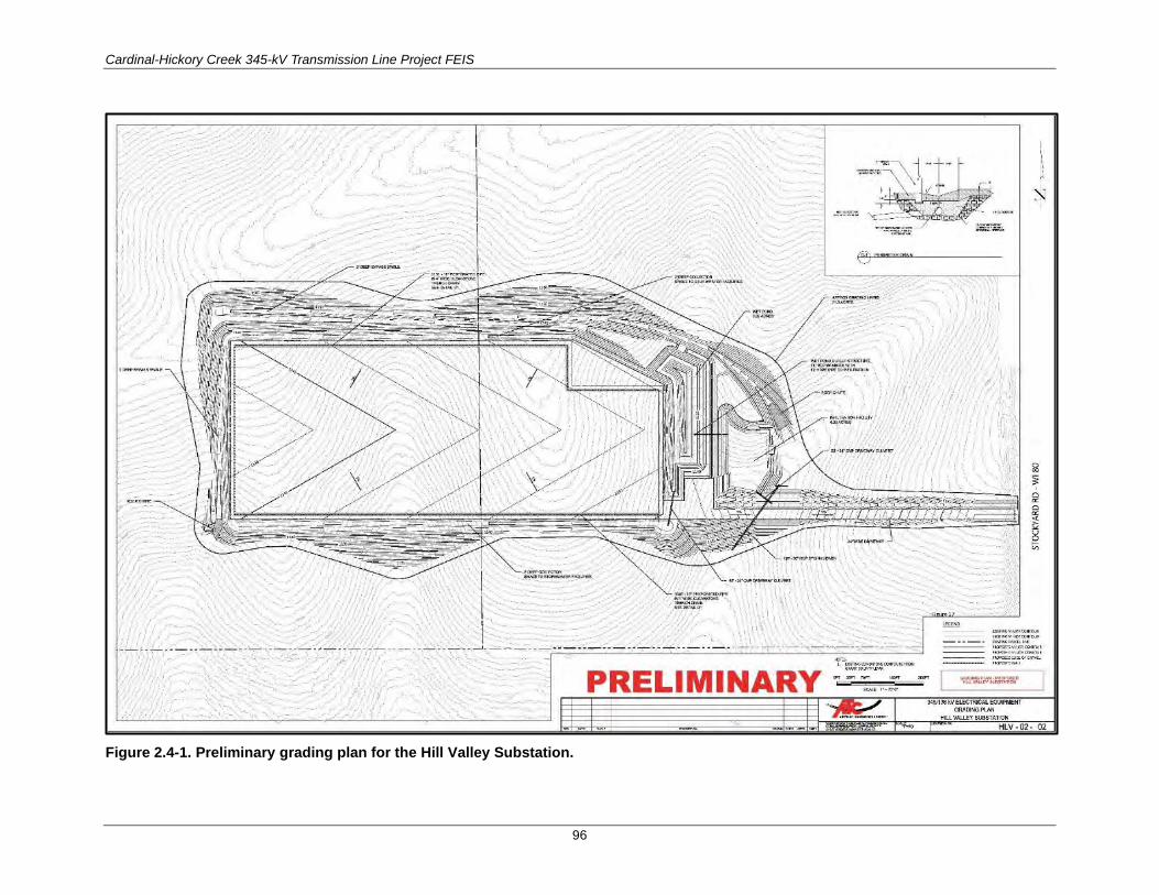
Cardinal-Hickory Creek 345-kV Transmission Line Project FEIS
96
Figure 2.4-1. Preliminary grading plan for the Hill Valley Substation.

Cardinal-Hickory Creek 345-kV Transmission Line Project FEIS
97
Turkey River Substation
Under all action alternatives, the Turkey River Substation in Clayton County, Iowa, would require the following additions:
• Three additional 161-kV circuit breakers
• Four new 69-kV circuit breakers
• One new 161/69-kV transformer.
Hickory Creek Substation
Under all action alternatives, the Hickory Creek Substation in Dubuque County, Iowa, a new 345-kV terminal, would be constructed within the existing fenced area.
2.4.1.2 Transmission Line Structures For most of the C-HC Project, the Utilities propose to use monopole steel structures that would typically be approximately 150 feet tall, with some structures ranging up to 175 feet tall, depending on site conditions. A typical 345-kV single-circuit structure is shown in Figure 2.4-2. Typical double-circuit structures are shown in Figure 2.4-3 for 345-/69-kV lines and in Figure 2.4-4 for 345-/138-kV lines. The structures would support the three-phase aluminum conductors steel reinforced (ACSR) cables for the C-HC Project 345-kV transmission line, in addition to two overhead shield wires for lightning protection and protective relay communications. At least one of the overhead shield wires would be fiber-optic cable and in certain locations both shield wires would be fiber-optic cable. Alternative structure designs might be used at some locations along the route to reduce potential impacts. For example, depending on the final route, the C-HC Project 345-kV line might be collocated with existing transmission lines. In some areas, the line would be designed as a double-circuit, but only a single 345-kV circuit would be installed as part of the C-HC Project. These double-circuited-capable structures would neither include the second lower-voltage conductor nor the braced post insulators. In Iowa, double-circuited-capable structures would be constructed between the Turkey River Substation and Hickory Creek Substation. Typical spans would be 500 to 1,200 feet between transmission line structures, depending on topography and other physical conditions considered during final design. Lights would be installed on transmission line structures if required by Federal Aviation Administration (FAA) permit. As of the printing of this FEIS, the only location where lighting may be required for transmission line structures would be in the Cassville, Wisconsin area, if Alternative 2, 3, or 4 is selected, because lights would be required for the Mississippi River crossing at the Stoneman Substation.
The collocated 345-/161-kV structures for the portion of the C-HC Project through the Refuge would primarily be low-profile, tubular-steel, approximately 75-foot-tall, horizontal-symmetrical H-frame structures, to minimize the likelihood of avian collisions. This lower, wider profile would require a 260- foot-wide ROW through the Refuge (Figure 2.4-5). Structures would be placed in concrete foundations with a typical span length of approximately 500 to 600 feet. To raise the height of the conductors to cross the Mississippi River, one transition structure would be required in the Refuge, between the other low-profile structures in the Refuge and the river-crossing structure. This transition structure would be approximately 80 to 90 feet tall and would have a 500- to 600-foot span length. The crossing structures on the banks of the Mississippi River also would be tubular-steel H-frame structures and would be approximately 196 feet tall (Figure 2.4-6).

Cardinal-Hickory Creek 345-kV Transmission Line Project FEIS
98
Figure 2.4-2. Typical 345-kV single-circuit monopole structure.
Figure 2.4-3. Typical 345-/69-kV double-circuit monopole structure.

Cardinal-Hickory Creek 345-kV Transmission Line Project FEIS
99
Figure 2.4-4. Typical 345-/138-kV up to 345-/ 345-kV double-circuit monopole structure.
Figure 2.4-5. Low-profile 345-/345-kV double-circuit structure for the Refuge crossing.

Cardinal-Hickory Creek 345-kV Transmission Line Project FEIS
100
Figure 2.4-6. Low-profile 345-/345-kV double-circuit structure for the Mississippi River crossing.
The C-HC Project transmission line at the Mississippi River crossing would be designed and constructed to double-circuit 345-/345-kV specifications, but it initially would be energized at 345-/161-kV until the need arises to increase the voltage of the 161-kV line to a 345-kV line. The increased capacity of the second circuit would avoid potential impacts to the Refuge if another future 345-kV transmission line is needed between Wisconsin and Iowa, because the line would already be constructed to carry the additional voltage. Regardless of the voltage configuration, there would only be one pair of double-circuit structures for crossing the Mississippi River, one on each side of the river.
The Mississippi River crossing structure heights and conductors tensioning/sag would be designed to meet or exceed the minimum clearances required above the navigable river channel, as defined by U.S. Coast Guard requirements. The Utilities would continue to work closely with the USFWS to identify the final design of the C-HC Project and to determine the most appropriate structure design to minimize wildlife and aesthetic impacts in the Refuge.
2.4.1.3 Structure Foundations 2.4.1.3.1 TYPICAL FOUNDATIONS
Two types of structure foundations would be primarily used for the C-HC Project: directly embedded structures and reinforced concrete caissons. Directly embedded structures tend to be more economical than concrete foundations and are typically used for tangent and small-angle structures. Soil conditions would determine the appropriate foundation type and the required dimensions of the drilled holes. Where

Cardinal-Hickory Creek 345-kV Transmission Line Project FEIS
101
poor soils conditions exist, deeper and wider excavations would be necessary. Typical equipment for this phase of construction would include dump trucks, drill rigs, cranes, vacuum trucks, and tanker trucks.
The Utilities estimate that an average area of 100 × 100 feet would be temporarily disturbed to install each foundation, with approximately 1,850 cubic yards of native cut-and-fill material per structure.
For directly embedded structures, the excavated holes would be 3 to 6 feet in diameter and 20 to 30 feet deep. Permanent disturbance would be approximately 6 feet in diameter per structure installed using this foundation type.
For reinforced concrete caissons, the excavated holes would be 5 to 12 feet in diameter and 20 to 60 feet deep. The volume of the holes would average 30 to 60 cubic yards, but could exceed 150 cubic yards for several of the largest foundations. Permanent disturbance would be up to 12 feet in diameter per structure installed using this foundation type.
2.4.1.3.2 ALTERNATIVE FOUNDATIONS
In some places, access would be limited or protection of natural resources would be paramount (or both), making alternative construction methods prudent for consideration. Alternative foundations that might be needed to construct the C-HC Project include micro-piles, helical piers, vibratory piles, and vibratory caissons. Once geotechnical studies are completed, the type and design of each foundation would be finalized, considering the soil/rock characteristics and to mitigate potential impacts in specific locations.
Micro-Pile Foundations
Micro-piles are a type of deep foundation with a high strength design consisting of a relatively small-diameter casing, rod, or both. The number and size that are used depend on the transmission structure weight, subsurface soil conditions and profiles at various depths, and lateral forces, such as wind and turning angles. Typically, there are three to 12 piles per transmission structure leg. A typical pile is approximately 5 inches in diameter in the upper section and as small as 1 inch in diameter at the bottom and could be 25 to over 50 feet deep. During construction, the micro-pile casing is drilled down to the design depth, an all-thread reinforcing steel bar is typically inserted, and high-strength cement grout is then pumped into the casing. The micro-pile is then commonly capped with concrete collars to which the transmission structure is bolted.
This type of foundation is suitable for remote rocky locations, such as the east and west bluffs of the Mississippi River and possibly other locations to be identified during final project design. The construction of micro-pile foundations would still require vehicle access to transmission structure sites, but small excavators and pick-up trucks could be used for construction rather than larger and heavier cranes and concrete trucks. Use of smaller equipment could reduce the potential environmental impacts.
Helical Pier Foundations
A second alternative foundation is a helical pier foundation, which is suitable for areas with high water tables, expansive soils, fill, or other unstable conditions where a deep foundation would typically be required. Helical piers are also known as screw piles. They are composed of a steel pipe shaft or solid bar with a screw or helix tip that, when rotated, pulls the shaft into the ground. Typically, three to six piers are used per transmission foundation or pole. The helical screws could be 6 to over 20 inches in diameter and, depending on the soil profile, the piers typically could be 10 to over 80 feet deep. A large hydraulic auger system twists the piles down through unsuitable soils to the more dense materials below, and measures the torque for the correct resistance for the design loadings. After the piers are installed, they are capped

Cardinal-Hickory Creek 345-kV Transmission Line Project FEIS
102
with concrete or a welded steel collar, to which transmission structures are bolted. This installation method would require no soil excavation or removal, as is common with other drilling techniques.
Helical pier foundations are also suitable for deep wet environments. The hydraulic augers can be installed using marsh buggies, minimizing the potential impacts to natural resources. In other transmission construction projects, the Utilities have used marsh buggies to access the construction sites during frozen conditions.
Vibratory Piles
Vibratory piles, or hammer-driven piles, are the most common driven-pile system and are used where poor soil conditions would result in otherwise excessively large drilled pier foundations. The pile can be an H-beam or pipe, and the hammers can be diesel or hydraulically driven. The number of piles per foundation depends on the loading requirements of the transmission structure and the soil conditions at various depths. Each pile would typically be 3 to 10 inches in diameter and could be up to 120 feet deep. The piles are often sectionalized and linked together to be driven to deeper depths. They are typically capped with steel.
Equipment used to construct these types of foundations is considerably heavier than that used for micro-piles. Vibratory piles require a large track-mounted crane for installation of the piles. The benefit of using vibratory or hammer-driven piles is that low ground-pressure track equipment can be used to minimize environmental impacts and the potential footprint of the impacts. Because concrete is not used, extensive matting is not required for concrete trucks to access the foundation sites.
Vibratory Caissons
Vibratory caisson foundations are directly embedded foundations that use a vibratory hydraulic hammering system to drive a single steel cylindrical foundation into the ground. They are typically used in sandy soils, saturated or very loose soils, and wetlands. These foundations can be many feet in diameter. For construction, the multisided hollow steel caisson is fitted with a temporary special cap for strength, and the vibrating machine forces it into the ground. The inside can be backfilled to various depths with material to prevent buckling and stress. This foundation can be constructed with either a crane that is driven to the location, or a helicopter-based vibratory caisson and hammer unit. However, helicopters can only be used to construct lightly loaded structure foundations, such as for tangent structures.
2.4.1.4 Insulators and Conductors For portions of the C-HC Project transmission line route that would be single circuited, the conductors would be supported by polymer, porcelain, or glass insulators in a V-string or I-string configuration. Where the proposed transmission line would be double circuited with an existing lower-voltage electric line, a mixture of polymer, porcelain, or glass string assemblies or polymer-braced post assemblies would be used for the lower-voltage circuit.
The C-HC transmission line would be energized at 345 kV. The Utilities propose to use a bundled pair of TP-477 kilo circular mils ACSR (Hawk) conductors for each phase of the 345-kV circuit. The aboveground midspan conductor height would be highly variable because of the topography along the routes but would be a minimum of 27 feet above the ground surface. The conductors for the Mississippi River crossing would be a bundled pair of TP-795 kilo circular mils ACSR (Drake) for each phase of the two crossing circuits, capable of accommodating a 345/345-kV line but would be operated at 345/161-kV.

Cardinal-Hickory Creek 345-kV Transmission Line Project FEIS
103
All structures would use two shield wires to help protect the conductors from lightning strikes. Depending on the transmission line configuration, the two shield wires could consist of one standard steel stranded wire, and one steel and aluminum stranded wire containing a 48-fiber-optic bundle core generally known as an optical ground wire, or OPGW), or two OPGWs. OPGWs provide lightning protection and a communication path. In the case of the Mississippi River crossing, there would be two OPGWs, both with a 144-fiber-optic bundle core. Two OPGWs, each with a 48-fiber-optic bundle core, would be installed between the Hickory Creek and Turkey River Substations as well as between the Nelson Dewey or Stoneman Substation (depending on the alternative) and the Hill Valley Substation.
2.4.1.5 Right-of-Way Requirements An electric transmission line ROW is a strip of land that an electric utility uses to construct, operate, maintain, or repair a power line. Transmission lines are often centered in the ROW, but they might be offset if all of the conductors are placed on one side of the structures. The structures (usually poles and cross arms) keep the conductors away from the ground, other objects, and each other. Structure height, type, and configuration, along with span length and ROW width, are interrelated. For example, to increase the distances between transmission structures, such as to avoid a field or to cross a river, structure heights and ROW widths might also have to be increased. Additionally, factors such as topography and the acuteness of turn angles affect ROW widths and structure heights.
Utilities negotiate with landowners to pay for and obtain a legal easement to use their land for a transmission line ROW. An easement agreement is the method by which a utility ensures that the transmission line ROW is kept clear of vegetation, buildings, and other structures that could interfere with the line’s operation. An easement agreement also provides the landowner certain land use controls and conditions.
The temporary C-HC Project transmission line construction ROW might be wider than the permanent ROW, to provide adequate room for the construction equipment to build the transmission line. Then the permanent C-HC Project transmission line ROW easement must be wide enough to keep the conductors a safe distance from buildings, trees, the ground, and other features as they hang between the transmission poles or other structures. Outside of the C-HC Project transmission line ROW, easements also might be needed for construction or operation and maintenance access roads, and for removal of hazard trees.
The C-HC Project would typically have a permanent 150-foot-wide ROW in Wisconsin and 200-foot-wide ROW in Iowa, based on design standards used by the Utilities in each state. In a few select locations the proposed ROW would vary from 70 to 260 feet wide. For example, the ROW would be 260 feet wide in the Refuge to accommodate the low-profile structures. In only a few locations, the ROW would be narrower than 150 feet to address pinch-points or constraints associated with other infrastructure. For much of its length, the C-HC Project ROW would share or overlap existing ROWs of other electric lines, roads, and railroads. The Utilities have stated that all new C-HC Project transmission line easements would be acquired where the project ROW overlaps other existing transmission line ROWs. The disposition of the existing, but potentially unneeded, transmission line easements would be determined on a case-by-case basis by the Utilities.
In a number of locations, there are existing lower-voltage electric lines along the proposed C-HC Project transmission line routes that would be relocated and double circuited with the new C-HC Project 345-kV line, using a portion of the existing ROW. In other cases, the Utilities propose to relocate the existing line elsewhere. In a few locations where lower-voltage transmission lines are poorly sited and use multiple-angle structures, the Utilities propose to double circuit the existing and new C-HC Project 345-kV transmission lines on a new ROW where there might be fewer impacts or a better alignment.

Cardinal-Hickory Creek 345-kV Transmission Line Project FEIS
104
2.4.1.6 Access Roads Wherever possible, the C-HC Project ROW would be accessed from existing public roads that intersect the ROW. Where public roads do not intersect the ROW, existing farm lanes (e.g., gravel or grassed two-track lanes), driveways, and cleared forest roads or trails would be used for access, along with existing waterway crossings such as bridges or culverts. Before construction begins on the C-HC Project transmission line, some of these existing access roads might need modifications and improvements to allow for safe equipment movement to and from the C-HC Project ROW. These modifications might include vegetation removal, grading, or gravel placement (or all three).
New access roads are sometimes needed where natural constraints, such as steep hills, large and/or high-quality wetlands due to their beneficial ecosystem services, or other limitations, do not allow direct access from existing public or private roads. The constraints the Utilities cite as requiring access roads would include slopes greater than 20%, river crossings wider than 12 feet, and access limitations along roads and railroads. Appendix C identifies the preliminary estimated number of access roads that have been identified by the Utilities for the alternative routes.
Access within wetlands might include using ice roads; completing work during dry or frozen conditions; or using low ground-pressure equipment, construction mats, or temporary construction bridges. Permanent wetland fill is not proposed for access roads. Any methods used in wetlands would be subject to applicable permitting review and approval.
Most of the access roads would be restored to pre-construction conditions after construction activities are complete. Depending on landowner negotiations and requirements, the improved access roads may be left in place. Some access roads may be required for long-term maintenance and safe operation of the transmission line.
2.4.2 Preconstruction Activities Preconstruction activities for the C-HC Project would include permit acquisition, installation of erosion control and other BMPs, surveying and staking, ROW clearing and matting, access road and laydown yard construction, site grading, and construction of temporary staging areas and conductor pulling sites. It is also important to note that local distribution companies often relocate their distribution facilities ahead of transmission line construction. If temporary removal or relocation of fences is necessary, the installation of temporary or permanent gates would be coordinated with the landowner. The C-HC Project ROW agent would also work with landowners for early harvest of crops, where possible.
2.4.2.1 Permitting and Installation of Environmental Commitments and Mitigation Measures
Most state and Federal permits must be acquired before the start of construction. Conditions of most or all of these approvals would usually require a number of preconstruction environmental surveys. C-HC Project environmental surveys would include the finalization of wetland boundaries, the presence or absence of specific protected species, the presence or absence of invasive species, or archaeological site boundaries that would likely be impacted by construction activities. To ensure that the Utilities have a complete and intact route, most negotiations with landowners would be concluded before the start of construction.
Different locations and soil conditions along the C-HC Project ROW would require different construction equipment and techniques, as well as a variety of environmental commitments and mitigation measures. Soil conditions and stability would be tested using preliminary boreholes, as part of final project design

Cardinal-Hickory Creek 345-kV Transmission Line Project FEIS
105
and before the start of construction. Soil borings are typically completed using rubber-tired or tracked drill rigs. Local variations in some conditions, such as the depth to bedrock, depth to the water table, or volume of rainfall, might require specific engineering or environmental solutions, environmental commitments, and mitigation measures during subsequent C-HC Project construction.
Installation of erosion control BMPs are location-specific and implemented prior to anticipated ground disturbance. Where unexpected ground disturbance occurs, BMPs are installed prior to or immediately after the disturbance occurs. Typical erosion control equipment includes all-terrain vehicles and trucks for crew transportation, as well as skid loaders, tractors, backhoes, hydro-seeders, and other light-duty equipment.
2.4.2.2 Survey and Staking Surveying and staking would be used throughout multiple phases of the C-HC Project. Some examples would be surveying and staking for locating and marking the ROW, environmentally sensitive areas boundaries, foundations or structure locations, property or section lines, underground and aboveground utilities, etc. Surveying and staking would be performed prior to and sometimes after construction activities such as constructability reviews, soil borings, laydown yards, clearing, foundations, and hole excavations. These activities are generally completed by a two-person crew travelling by foot, all-terrain vehicle (ATV), or pick-up truck.
2.4.2.3 Right-of-Way Clearing and Matting For the majority of the C-HC Project ROW, the full width of the ROW would be cleared before the start of construction. However, in a few unique places where the routes would cross hilly terrain, tree clearing might be avoided or minimized due to the existing adequate clearances between the proposed conductors and tree heights. Where these areas exist, some woody vegetation could be left in place, provided that the vegetation posed no safety or reliability concerns to the transmission line and that the trees would not interfere with access to the electric facilities during construction and long-term maintenance. Identification of these areas would require additional surveys at each location to determine the ground elevations, anticipated mature tree heights, and maximum line-loading conditions. These locations would be identified during final engineering of the C-HC Project.
In upland shrubby grasslands and cropped fields, the C-HC Project ROW would be cleared with a mower. Other vegetation would be cut at or slightly above the ground surface by hand or by using mechanized mowers, sky trims, processors, or harvesters. Rootstocks would generally be left in place, except in areas where stump grinding would be necessary to facilitate the movement of construction vehicles. Woody vegetation might be chipped with a forestry mower or a chipper and scattered over the ROW in nonagricultural upland areas. In wetlands or floodplains, care would be taken to ensure that the mowed or chipped material is spread in accordance with the requirements of any necessary permits.
During the clearing process, matting might be installed to ensure stable work conditions in wetlands and unstable soil areas (Figure 2.4-7 and Figure 2.4-8), or to provide temporary bridges across waterways (Figure 2.4-9). Mats also could reduce rutting and excessive soil disturbance, as well as impede the spread of invasive species. Construction matting would be installed with rubber-tired mat trucks, forwarders, forklifts, or skid loaders. Mat access roads would generally be 16 to 20 feet wide and mat work platforms for structures might be 100 × 100 feet or more, depending on the type of transmission structure used. In many cases, these mats would be left in place through all phases of construction.
If the C-HC Project transmission line follows an existing transmission ROW, existing transmission structures would be removed after new structures are installed due to outage constraints associated with
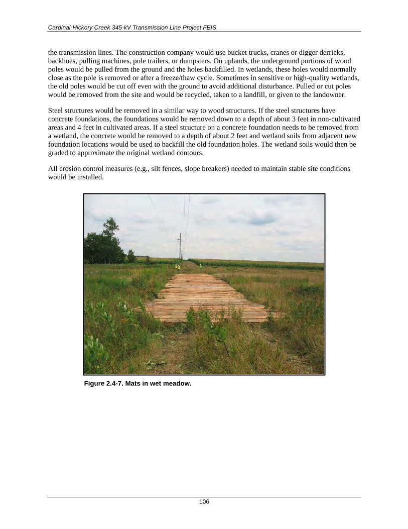
Cardinal-Hickory Creek 345-kV Transmission Line Project FEIS
106
the transmission lines. The construction company would use bucket trucks, cranes or digger derricks, backhoes, pulling machines, pole trailers, or dumpsters. On uplands, the underground portions of wood poles would be pulled from the ground and the holes backfilled. In wetlands, these holes would normally close as the pole is removed or after a freeze/thaw cycle. Sometimes in sensitive or high-quality wetlands, the old poles would be cut off even with the ground to avoid additional disturbance. Pulled or cut poles would be removed from the site and would be recycled, taken to a landfill, or given to the landowner.
Steel structures would be removed in a similar way to wood structures. If the steel structures have concrete foundations, the foundations would be removed down to a depth of about 3 feet in non-cultivated areas and 4 feet in cultivated areas. If a steel structure on a concrete foundation needs to be removed from a wetland, the concrete would be removed to a depth of about 2 feet and wetland soils from adjacent new foundation locations would be used to backfill the old foundation holes. The wetland soils would then be graded to approximate the original wetland contours.
All erosion control measures (e.g., silt fences, slope breakers) needed to maintain stable site conditions would be installed.
Figure 2.4-7. Mats in wet meadow.
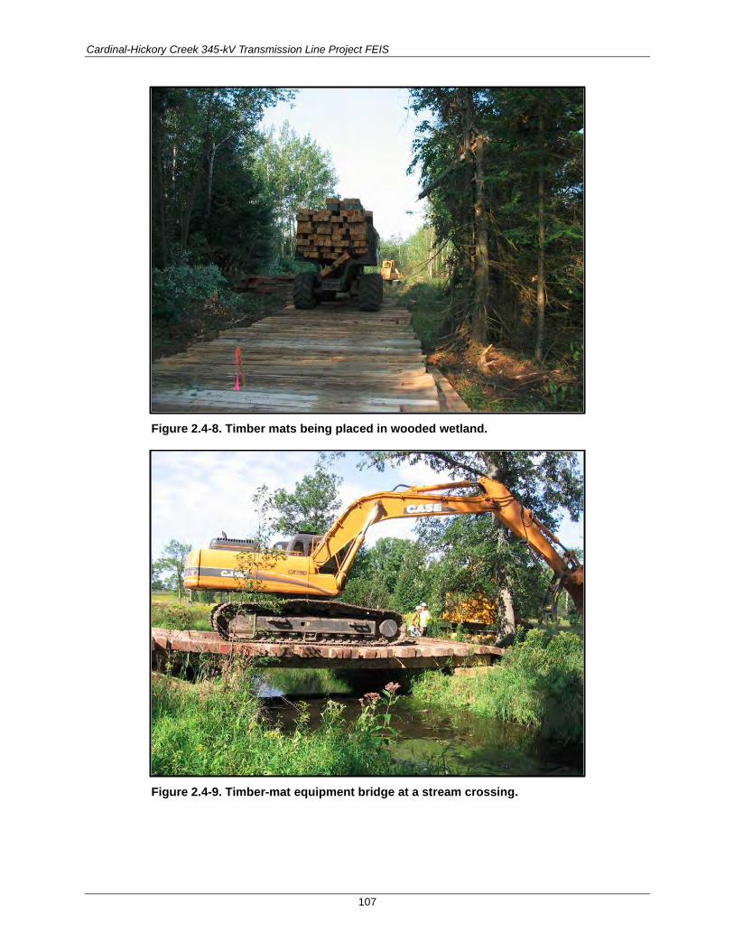
Cardinal-Hickory Creek 345-kV Transmission Line Project FEIS
107
Figure 2.4-8. Timber mats being placed in wooded wetland.
Figure 2.4-9. Timber-mat equipment bridge at a stream crossing.

Cardinal-Hickory Creek 345-kV Transmission Line Project FEIS
108
2.4.2.4 Access Road Construction and Site Grading All construction materials, equipment, and labor would be brought to remote foundation sites over temporary access roads, using special matting, where required, to protect the underlying soils and vegetation. Some of the existing access roads might require modifications and improvements to allow for safe equipment movement to and from the C-HC Project ROW, and some new access roads and work platforms might have to be constructed. Access roadbeds would typically have to be 14 to 20 feet wide, and work platforms would be at least 30 × 30 feet to minimize difficult grading in steeper topography. Work areas would be up to 100 × 200 feet in flatter areas, which allows for a more efficient workspace. Modifications could include vegetation removal, grading, and/or gravel placement. This work would typically be completed using bulldozers, trackhoes, skid-loaders, and dump trucks.
Access within wetlands would include one or more of the following construction methods: 1) completing work during dry or frozen conditions, 2) using low ground-pressure equipment, and/or 3) using temporary construction mats. The Utilities are not proposing permanent wetland fills for improving existing access roads or constructing new temporary access roads. Where grading or the placement of gravel is required, erosion control or stormwater BMPs would be implemented.
Transmission line structures are generally installed at existing grades. However, in areas with more than 10% slopes, structure sites and work areas would have to be graded level or fill, or mats would have to be brought in to create working pads. Work pads or platforms would be at least 30 × 30 feet to minimize difficult grading in steeper topography. Work areas would be up to 100 × 200 feet in flatter areas, which allows for a more efficient workspace.
In locations where C-HC Project structures would be constructed within or in proximity to a highway ROW, the Utilities would have to communicate with the appropriate state department of transportation to determine suitable structure locations and grade restoration to prevent erosion and maintain appropriate surface water drainage along the highway.
2.4.2.5 Temporary Staging Areas and Conductor Pulling Sites During construction, temporary staging/laydown areas, helicopter landing pads, and conductor pulling/handling sites would be required. Temporary off-site laydown yards might be needed, depending on access, security, efficiency, and safety for warehousing supplies. These yards would be used to store job trailers, construction vehicles and equipment, transmission line structures, conductors, cables, and other related materials and equipment. A typical laydown yard would be about 10 acres, with a minimum of a 30-foot-wide driveway for ingress and egress. Laydown yard locations are shown on Figure 2.3-2, Figure 2.3-4, Figure 2.3-6, Figure 2.3-8, Figure 2.3-10, and Figure 2.3-12. Laydown yards would be selected to minimize the amount of disturbance and preparation required from grading and clearing, such as paved sites, parking lots, old gravel pits, and fields. Additional smaller staging areas would be located along the C-HC Project ROW to store construction materials and for structure laydown and framing before installation. Often these sites are on agricultural lands that are temporarily taken out of production (with compensation to the landowner) for the purpose of temporarily storing tower sections, reels of conductor, and other necessary components.
Helicopter landing zones/pads also might be required. Preferred sites would be in close proximity to the C-HC Project ROW, relatively flat (1% to 2% slope), require minimal site preparation, and would be free of obstructions, such as vacant parking lots, quarries, gravel pits, or fallow fields. Depending on the type of helicopter used, a temporary 50 × 50–foot landing pad or a 1- to 2-acre helicopter laydown yard would be needed for structure assembly, and equipment and material storage. Typical spacing between helicopter landing zones would be 3 to 7 miles.

Cardinal-Hickory Creek 345-kV Transmission Line Project FEIS
109
Temporary conductor pulling/handling sites would also be required. A typical conductor pulling/handling site would be approximately 40 × 300 feet and would be spaced approximately every 10,000 feet, depending on the type of conductor to be used.
2.4.3 Construction Activities Major construction activities for the C-HC Project include augering and blasting for foundations, foundation installation, structure erecting, constructor stringing, substation construction, and site restoration. During construction, the Utilities might ask the landowners to remove or relocate equipment and livestock from the C-HC Project ROW. Disturbances would likely occur in the areas immediately surrounding C-HC Project transmission line structures. Construction is estimated to occur over a two-year period.
2.4.3.1 Augering and Blasting for Foundations In most soils, C-HC Project transmission line structure foundations could be excavated using an auger on a standard drilling rig (Figure 2.4-10). The augered soils would be temporarily piled off to the side of the excavation, in upland locations. Sensitive upland areas would be avoided as discussed in further detail in Chapter 3. If contaminated materials are encountered during the construction, spoils would be isolated, and steps would be taken to determine disposal requirements in accordance with applicable regulations. In wetlands and agricultural fields, the topsoil would be segregated from the subsoils and stockpiled off to the side. In wetlands, the subsoils would often be piled on timber matting, or on a geotextile fabric for disposal at a later time (Figure 2.4-11). Stockpiled materials would be prevented from entering any wetlands or waterways by the use of proper erosion control methods, such as silt fence, silt socks, or wattles.
If the water table is encountered during the augering process, dewatering might be required. Options for dewatering would include pumping the water from the excavation to a suitable upland area and allowing it to be slowly released into a drain field and to slowly percolate into the soil, pumping water into silt cells or bags to allow silt to drop out, or pumping the water directly into a tanker truck and transporting it to a suitable upland for release onto the soil surface.
When subsurface soils consist of unconsolidated materials, such as gravel or cobbles, the excavation site might alternatively have to be filled with water to prevent the sidewalls from collapsing. The water pressure would keep the walls of the excavation intact during the augering process. When the appropriate depth is reached, a casing would be inserted into the excavation and the water would be pumped out and disposed of as described for dewatering, above.
When bedrock is close to the soil surface or when subsoils primarily consist of large boulders and large cobbles, blasting might be required to complete the structure excavation. Explosives would be placed in holes drilled into the rock, and the structure site would be covered with blasting mats to keep the rock and debris loosened by the blast from scattering over a wide area. Following the blast, the blasting mats and loosened debris would be removed, and the drilling rig would be used to auger through the broken rock until the appropriate depth is reached. Based on preliminary geotechnical information available at the time of printing this FEIS, blasting is not expected to be a necessary construction technique for the C-HC Project. However, if unanticipated geotechnical conditions are discovered, blasting may be the best method for excavating foundations.

Cardinal-Hickory Creek 345-kV Transmission Line Project FEIS
110
Figure 2.4-10. Foundation excavation using an auger in dry upland soils.
Figure 2.4-11. Structure location in a wetland—matted work platform, foundation, spoil pile (to be removed), and erosion control.

Cardinal-Hickory Creek 345-kV Transmission Line Project FEIS
111
2.4.3.2 Foundation Installation The installation method used and the diameter and depth of the foundations for the C-HC Project would vary depending on the soil characteristics and structure loadings. Excavation would be required for all structures, whether they are directly embedded or use reinforced concrete foundations.
For directly embedded structures (i.e., where no concrete foundation would be required), a hole would be excavated to the appropriate depth. The integrity of the hole might be protected with the installation of a permanent culvert. The base of the structure would be placed into the excavated hole or, if soils are unstable, into a culvert, and the area around the structure would be backfilled with clean granular fill.
For structures requiring a reinforced concrete foundation, the required hole would be excavated, and a rebar cage and anchor bolts would be placed into the excavation. The excavation would then be filled with concrete to cover the rebar cage and anchor bolts, except for a typical 1- to 2-foot reveal of the foundation abovegrade with exposed threaded anchor bolts. The complete caisson would be allowed to cure. Typical equipment for this phase of construction would include dump trucks, drill rigs, cranes, vacuum trucks, concrete mixers, and tanker trucks.
2.4.3.3 Structure Erecting and Conductor Stringing The structure sections would be transported to the foundation sites from a staging site in the C-HC Project area, where they would have been initially stored. Steel transmission structures are erected in sections. Cranes would be used to lift the structure sections into place (Figure 2.4-12). First, the lower section would be lifted into place and bolted onto the concrete foundation. The upper sections of the structure, with the arms already attached, would then be lifted onto the lower structure section. Sometimes insulators and large pulleys that facilitate wire stringing would also be attached to the structure arms before they are raised into position. Alternatively, the pulleys could be attached after structure erection is completed.
In areas where ground-based cranes would not be suitable due to soft or wet ground, steep terrain, or environmentally protected areas, helicopters could be used to transport and erect the steel structures (Figure 2.4-13). Heavy-lift helicopters might be used to transport equipment and materials, including the tower components, to remote locations. Helicopters can provide a low-impact alternative for almost all phases of construction. In some difficult locations, their use might reduce required construction time, allow work in remote or inaccessible locations, eliminate the need for extensive road building, reduce the construction footprint considerably, and reduce environmental impacts.
Large reels of rope then would be staged on the C-HC Project ROW, and individual ropes would be drawn through pulleys from structure to structure. The conductors would then be attached to the ropes and pulled into place (Figure 2.4-14). Pulling sites would be spaced about 10,000 feet apart. The pulleys then would be removed, and the conductors would be attached to the insulators and properly tensioned. If the conductors are double bundled, spacers might be inserted at appropriate distances along the conductors. In some situations, implosives could be used to splice the conductors. Light-duty helicopters might be used along the entire length of the C-HC Project ROW in stringing operations, including the installation of conductors, shield wires, and bird diverters.
Sometimes when it is necessary to maintain electrical system reliability during construction, temporary transmission lines and poles might be constructed on one side of an existing ROW. Temporary lines are typically supported by wood poles directly embedded into the ground, with post insulators. These lines would be removed when construction of the new C-HC Project transmission line is completed, and they are no longer needed.

Cardinal-Hickory Creek 345-kV Transmission Line Project FEIS
112
Figure 2.4-12. Installing the top section of a structure with a crane.
Figure 2.4-13. Installing a structure on a foundation with a helicopter.

Cardinal-Hickory Creek 345-kV Transmission Line Project FEIS
113
Figure 2.4-14. Pulling the conductor through the structure arms.
2.4.3.4 Substation Construction Construction activities at the proposed Hill Valley Substation would include site preparation, clearing and grading, foundation installation, and equipment installation. Site preparation would include installing erosion control BMPs, stripping topsoil, and hauling in structural fill to build up the subgrade for the substation pad. Spoil disposal could include transferring the material to an adjacent landowner or other user who needs fill material. The Utilities’ standard practice is to avoid disposing of clean soil in a landfill, if possible.
Clearing and grading would be required for the new substation site. The area would be graded to level the substation site and install stormwater facilities and the driveway. The Utilities estimate that grading the site would result in approximately 80,000 cubic yards of earth cutting over 8.5 acres. This soil would then be used on-site to fill about 7 acres of areas with lower elevations. Soils would be imported onto or exported from the site.
Construction within the newly created substation pad would consist of drilled pier foundations ranging in size from 3 to 7 feet in diameter and 10 to 25 feet deep. The foundations would be installed to support transmission line dead-end structures, static masts, and bus and equipment support structures. Slabs-on-grade 9 × 32 feet and up to 3 feet thick would be used for 345-kV circuit breakers, and 8 feet square × 2 feet thick would be used for 138-kV circuit breakers. The control building would be supported by a perimeter wall up to 5 feet deep set on a spread footer with pier supports. Transformer and reactor secondary oil containment would be a concrete-lined pot filled with stone. Conduit for control and communication cables and grounding conductor would be installed prior to the placement of the final layer of crushed rock surfacing. The ground grid would be installed 18 inches below the subgrade surface throughout the substation pad and extend 5 feet outside the substation security wall.
Cardinal-Hickory Creek 345-kV Transmission Line Project FEIS
114
Construction also includes installation of stormwater facilities. Facilities would be designed in accordance with State of Wisconsin long-term stormwater management performance requirements and erosion controls, as stated in WAC Chapters NR 216 and NR 151. For sites containing up to 40% connected impervious areas, 90% of the pre-development infiltration volume would be infiltrated. In addition, BMPs would be implemented so that no more than 5 tons per acre per year of the sediment load carried in runoff would be discharged from initial grading to final stabilization.
Once the substation pad is built to the subgrade, all areas would be restored, and the site would be ready for use.
2.4.3.5 Site Restoration Site restoration, including revegetation where necessary, would be completed as construction activities are completed in portions of the project area, in accordance with permit conditions, weather, ground conditions, and/or growing season, all of which help inform the best time for restoration efforts to occur. The need for and approach to site restoration and revegetation would be based on the degree of disturbance caused by construction activities and the ecological setting of each site and would comply with the easement agreements previously established with the landowners. If the landowners permit it, the Utilities would prefer to leave leveled areas and working pads in place for future C-HC Project maintenance activities. Otherwise, the sites would be graded back to their original conditions as much as possible, and all imported fill would be removed and hauled to an approved disposal site.
The excavated topsoils would be replaced and spread in a thin layer on surrounding upland areas around the structure sites and stabilized, to ensure optimal conditions for revegetation. If construction and access in any particular location could be accomplished without creating appreciable soil disturbance, restoration might not require active revegetation efforts. In some cases, where it is reasonable to allow the natural ground cover to reestablish itself, the underlying perennial vegetation would usually reestablish within one growing season. Annual grasses might also be sown to minimize the potential for erosion while reestablishment is occurring. In cases where there is no sign of regrowth of preexisting vegetation species in the first month of the subsequent growing season, an assessment would be made, and if necessary, an appropriate seed mix, consistent with the surrounding vegetation, would be brought in and properly applied.
New topsoil would be brought in and spread on agricultural lands where it was lost or seriously mixed with subsoils. Compacted agricultural soils would be decompacted to return the soil structure to its original condition. Any drainage tiles or other agricultural features that were damaged by construction activities would be repaired or replaced, or the landowner would be compensated.
Areas where crops are not present, such as roadsides, pastures, old fields, upland woods, and wetlands, would be seeded with native seed mixes or other appropriate, non-invasive or non-nuisance seed mixes, and then weed-free mulch would be laid down. In wetlands, excavated surface soils or the organic layer containing the plant parts and rootstocks of native wetland vegetation could be spread around the disturbed areas to enhance the reestablishment of the original wetland vegetation, if deemed appropriate by the necessary Clean Water Act permits.
The matting, temporary bridges, and construction-related materials would be removed at the completion of each stage of construction. Most of the new or improved C-HC Project access roads would be restored to preconstruction conditions and weed-free mulch would be spread evenly so that it does not hinder revegetation. However, some of the access roads might be retained for long-term maintenance and operation of the C-HC Project transmission line, and others might be left in place to comply with landowner easements. Following completion of restoration and reestablishment of vegetation within the
Cardinal-Hickory Creek 345-kV Transmission Line Project FEIS
115
ROW, all temporary restoration erosion control devices not designed to be left in place (e.g., sediment logs and silt fencing) would be removed and properly disposed.
In residential and urban areas where all vegetation has been removed, negotiated easements might require replacing vegetation with landscaping and low-growing shrubs and grasses. Species used for vegetation replacement would be similar to the vegetation in the surrounding area and would not be nuisance or invasive species, according to applicable state and Federal lists. These plantings would have to comply with the Utilities’ vegetation management plans, however, and must not impede maintenance activities for the new line. Any driveways, curbs, or roads damaged during the construction of the line would need to be repaired or replaced.
Restoration of disturbed areas would comply with Wisconsin Department of Natural Resources (WDNR) Technical Standards/BMPs (WDNR 2018a) or Iowa Department of Natural Resources (IDNR) BMPs (IDNR 2006). During active construction and ROW restoration, revegetation and restoration activities would be inspected, and written documentation of the inspection would be maintained describing the revegetation progress and corrective measures taken, if applicable. Site restoration activities would be implemented, monitored, and remedial measures applied (as necessary) until established restoration goals are achieved, as required by regulatory permits obtained for the C-HC Project. The Utilities would adhere to the environmental commitments enumerated in Table 3.1-4 and to the BMPs listed in Appendix D. During restoration, erosion and sediment control measures, including measures for stabilization of disturbed areas during and at the completion of construction, would be implemented as defined in the Stormwater Pollution Prevention Plan (SWPPP) developed for the C-HC Project. Areas where ground disturbance occurs would be monitored until 70% revegetation has been established. In non-agricultural area where ground disturbance occurs, the area would be monitored until the ground cover has been reestablished to at least 70% of the vegetation type, density, and distribution that was documented in the area prior to construction. In areas that were previously forested, disturbed areas would be revegetated consistent with the non-invasive herbaceous vegetation that occurs in the area.
2.4.4 Operation and Maintenance Activities NERC has established reliability standards for transmission line ROW vegetation management on transmission line systems. These standards apply to all transmission line owners in North America. NERC is also responsible for compliance review and enforcement. Because of the NERC reliability standards, the type of vegetation allowed to regrow in the new C-HC Project ROW would be based on its potential to interfere with the conductors and each landowner’s easement contract.
The Utilities would also be required to maintain their ROW and clearances in accordance with the adoption of the National Electrical Safety Code by Iowa and Wisconsin.
NERC generally requires the pruning or removal of interfering trees, to minimize the risk of vegetation-related outages. Otherwise, there would be an increased potential for fires or electrical or mechanical damages to the electrical equipment.
Thus, during C-HC Project operation, the Utilities would be required to maintain the ROW so that vegetation is kept at safe distances from the conductors. The ROW under the conductors (sometimes referred to as the wire zone), and any additional ROW width that is deemed necessary for conductor maintenance and repair, would be maintained in low-growing, non-woody plants and grasses. Other incompatible vegetation would be removed off-site or chipped and mulched within the ROW. ROW maintenance would be accomplished by performing routine vegetation maintenance through manual or mechanical vegetation removal and/or herbicide applications. Manual vegetation removal could include the use of chainsaws, brush cutters, loppers, and other hand tools to selectively remove incompatible

Cardinal-Hickory Creek 345-kV Transmission Line Project FEIS
116
vegetation. Mechanical vegetation removal could include the use of forestry mowers, aerial saws, lift trucks, wood chippers, and other mechanical equipment. Herbicides are chemicals substances used to control undesirable vegetation by interfering with specific physiological and biochemical pathways. Mechanical cutting of woody species, without the appropriate application of herbicide, can lead to more impactful and costly management to maintain the same clearance between vegetation and electric facilities. The selective use of herbicide can curtail the growth of incompatible vegetation and preserve compatible low-growing communities within the ROW.
The Utilities would employ a Certified Pesticide Applicator for all herbicide applications within the C-HC Project. The Certified Pesticide Applicators would only use herbicides registered and labeled by the USEPA and would follow all herbicide product label requirements. Herbicides approved for use in wetland and aquatic environments would be used in accordance with label requirements, as conditions warrant. During the easement negotiation, landowners can decline the use of herbicides for vegetation management activities once the line is in operation. Therefore, no herbicide would be applied within portions of the ROW on which the landowner wishes not to introduce it.
Herbicide application methods can include high-volume foliar, cut stubble, low-volume foliar, cut-stump, and basal applications. The herbicide type, mix, and application method used within the ROW would depend on the following:
• Vegetation density, size, and location
• Time of year
• Control method implemented
• Environmental conditions
• Property owner or easement restrictions
After construction, the Utilities would continue to monitor the ROW for vegetation growth and determine which vegetation management methods are to be used at each location or area along the ROW. The Utilities may determine the need for herbicide application as an effective method for vegetation maintenance. If used, follow-up herbicide applications would be based on vegetation growth conditions. Application methods and herbicides would be determined prior to its use.
In the remaining ROW width (sometimes referred to as the border zone), from the wire zone to the edge of the ROW, the Utilities might decide to allow low-growing and minimally dense woody vegetation. But anything located in the border zone could be removed, if it is not specified in the easement contract or if there is a change to the operation or maintenance requirements of the electrical facilities. Easement rights vary depending on the language used in the contract. The Utilities reserve the right to trim and remove all trees and shrubs for the full width of the easement. To the extent practicable, the Utilities would attempt to conduct routine maintenance in threatened and endangered avian species habitat outside of the migratory bird nesting season. The Utilities’ maintenance crews are trained to identify and avoid active nests during vegetation-clearing activities.
Outside of the C-HC Project ROW, the Utilities might complete additional tree trimming or removal. Under WAC Public Service Commission (PSC) 113.0512, transmission owners are required to trim or remove other trees that could pose a threat to the transmission line even if those trees occur outside the border zone and the project ROW. These are classified as “hazard” trees, which pose an unacceptable risk of falling and contacting the transmission line before the next ROW maintenance cycle. In Iowa, the 200- foot ROW would accommodate all necessary vegetation management, including the removal of hazard trees, to occur only within the ROW to protect the transmission line.

Cardinal-Hickory Creek 345-kV Transmission Line Project FEIS
117
2.4.5 Retirement of the N-9 Transmission Line and Construction of a New 69-kV Tap
Under all action alternatives, upon completion the C-HC Project construction and energization at the Turkey River Substation, Dairyland would retire and decommission approximately 2.8 miles of the existing N-9 transmission line (69-kV) starting at the Stoneman Substation, in Cassville, Wisconsin then crossing the Mississippi River and ending approximately 0.2 mile north of the Turkey River Substation in Clayton County, Iowa (Figure 2.4-15). A new segment of the N-9 transmission line would be built to connect the existing N-9 transmission line with the Turkey River Substation (Figure 2.4-16). This new segment would be approximately 0.2 miles long and cross private lands and portions of the public ROW for 360th Street and Great River Road (CY9). Under Action Alternatives 2, 3, and 4, the tap line must be installed before the N-9 line could be retired. Dairyland is proposing to decommission the N-9 transmission line in the winter months. It is anticipated that the action would take approximately 2 months (decommission the existing transmission line and building the new connection with the Turkey River Substation).
Prior to decommissioning activities, an erosion control plan would be developed to identify methods for preventing and mitigating soil erosion. The decommissioning of the N-9 transmission line would require the removal of 27 structures: one in Wisconsin, 21 structures within the Refuge, and five structures on private property in Iowa. The majority of the structures to be removed are single wood pole H-frame structures. Within the Refuge, there are four steel lattice structures at the Mississippi River crossing location. The conductors and shield wire would be collected on wire reels. Once the conductor and shield wires are removed, the structures would be removed and hauled off-site for reuse or disposal. Then, the holes where the structures were located would be filled. Smaller structures would be removed by trucks and ground equipment. In wetlands, all of the structures may be cut off at ground level to minimize impacts to the wetlands. For structures located on privately owned lands, the Utilities would work with the landowners to determine if the structures can be cut at ground level or pulled out of the ground, and the remaining holes would be filled with topsoil.
Within the Refuge, there are four river-crossing lattice structures requiring a crane for removal. The existing lattice structure foundations would be removed to 4 feet below the ground surface and the remaining foundation would be covered with clean fill. Once the structures have been dismantled the material would be recycled. Two temporary pads would be built adjacent to the steel structures on which the cranes and trucks would be placed. The pads would be 25 × 25 feet and would be built with wooden timber construction mats.
Typical equipment used for this type of action includes cranes, bucket trucks, reel trailers, wirepullers, and related stringing equipment. Ground access is proposed with the use of tracked equipment in areas of stable soil or with the use of construction mats for areas with unstable soil. The use of temporary small construction bridges with construction mats is anticipated for crossing small channels. Dairyland would use ice bridges to cross any wetlands located along the existing N-9 transmission line ROW. If the wetland soils are not frozen, construction would be performed in these areas using construction mats and air bridge matting. Air bridges are used in construction zones to support the weight of heavy equipment while protecting underlying pipeline, culvert, or other subterranean material that needs to be bridged. Operators do not permit heavy equipment to be driven over utilities. In this instance, cranes and loaders would be used as crews set out mats singly, so no piece of construction equipment ever touches the wetland. The support mats would be placed perpendicular to the main road decking, allowing the weight of the machinery to be dispersed across a large area. The road deck mats rest on those foundation mats, allowing the road deck to actually float on the wetland's vegetative layer, providing virtually no adverse impact to the wetland ecosystem.

Cardinal-Hickory Creek 345-kV Transmission Line Project FEIS
118
Figure 2.4-15. N-9 transmission line overview map.
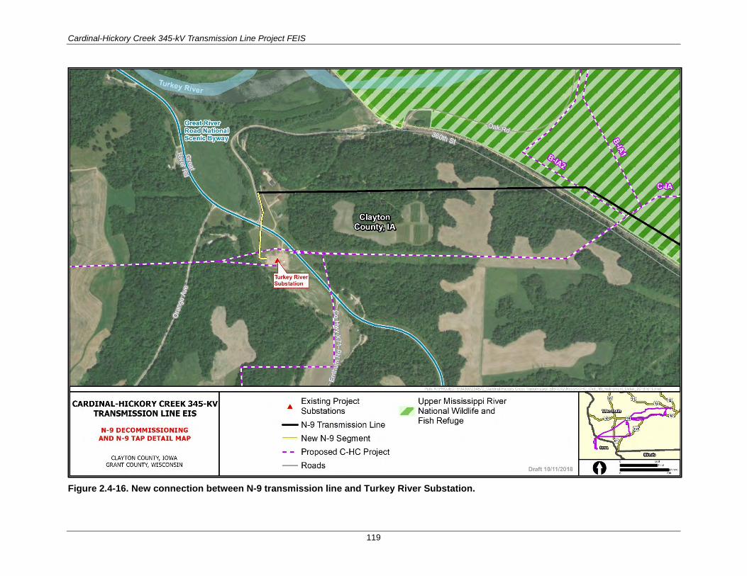
Cardinal-Hickory Creek 345-kV Transmission Line Project FEIS
119
Figure 2.4-16. New connection between N-9 transmission line and Turkey River Substation.

Cardinal-Hickory Creek 345-kV Transmission Line Project FEIS
120
The majority of the access routes would follow the existing ROW and existing access routes used by operation and maintenance crews. No new roads would be constructed and/or decommissioned as part of the action. Construction access methods through wetlands would be planned to minimize ground disturbance and may include but are not limited to construction mats and bridging, low ground-pressure equipment and restricting the length and width of the access route. Temporary fill, gravel, or rock is not anticipated for access to any of the sites along the N-9 transmission line.
Upon completion of the decommissioning of the N-9 transmission line, all temporary construction matting used for access routes and temporary work areas would be removed either by conventional equipment or low ground-pressure equipment. Estimated temporary access route and structure pad impacts would be calculated for each structure option when permit applications are prepared. Dairyland would use the same laydown sites identified for the construction of the C-HC Project.
A vegetation restoration plan would be developed in coordination with the USFWS and the USACE at the time of filing the special use permit application. The restoration plan would follow Dairyland’s BMPs, environmental commitments enumerated in the Section 3.1, Table 3.1-4, BMPs described in Appendix D, and agency input. Dairyland would also obtain an erosion control permit from the IDNR. Restoration on private property would be negotiated with each of the landowners at the time of removal.
Dairyland’s IUB franchise E-21927 would stay intact until the decommissioning of the N-9 transmission line is complete. After that time, Dairyland would file a request to the IUB to amend the franchise. Dairyland would petition the IUB for a new 69-kV electrical transmission franchise from the termini of the N-9 transmission line to the existing Turkey River Substation (see Figure 2.4-16).
2.4.6 Decommissioning At the end of its service life, the C-HC Project would be removed if the facilities are no longer needed. The decommissioning of the transmission line would involve the removal of wire, insulators, hardware, and structures from the ROW. Structures and foundations would be removed to below ground surface. Foundations and direct-embedded structures would be removed deep enough below ground surface to allow for the historical land use. For agricultural land, foundations would be removed to a depth that would allow for tilling, and clean fill would be spread on top. In other areas, the foundations would be removed and the land would be revegetated. Material would be disposed of in an appropriate manner. Wire and steel would be salvaged and sold; if structures are in good condition, some may be sold to utilities for reuse. The equipment required to safely remove the wires and structures would be nearly the same as that required for installation. Depending on the ground conditions, construction matting and tracked equipment may be used. Typical equipment would include cranes, bucket trucks, reel trailers, wirepullers, and related stringing equipment. After the decommissioning is completed, all temporary matting (if used) would be removed by either the equipment stated previously or tracked equipment.
Similarly, if the project substations are no longer required, the substation structures and equipment would be dismantled and removed from the site. Substations would be similarly decommissioned, with all remaining equipment disposed of in an appropriate manner and foundations cut off 1 foot below ground. The substation structures would be disassembled and either reused at another station, sold for scrap, or recycled. Major equipment, such as breakers, transformers, and reactors, would be removed, refurbished, and stored for use at another facility, depending on the age and condition of the equipment. Foundations would be either abandoned in place or cut off below ground level and buried.

Cardinal-Hickory Creek 345-kV Transmission Line Project FEIS
121
2.5 COMPARISON OF ALTERNATIVES Table 2.5-1 presents a summary comparison of potential impacts to resources analyzed in Chapter 3 for each action alternative. There are a few key pieces of information that are important for the reader to keep in mind while reviewing this summary table. The reader is referred to Chapter 3 for a definition of the area of analysis for each resource. Although several of the resources analyzed in Chapter 3 assess potential impacts to areas extending beyond the transmission line ROW, the impacts presented for comparison here are limited to just those impacts that would occur within the transmission line ROW, as these impacts account for the majority of impacts from the C-HC Project. See Chapter 3 for additional detail on potential impacts assessed beyond the transmission line ROW, as well as impacts common to all alternatives for each resource. Lastly, there are a few common impact indicators that are used to assess impacts to several resources. For example, wetlands and prime farmland are used as impact indicators for geology and soils, vegetation, land use, and socioeconomics. In these cases, the impact indicator (such as prime farmland) is presented in the primary resource (such as land use) but may also be mentioned in another resource group. These instances are not intended to confuse the reader or to appear as if the resource was analyzed more than once with varying results. For clarification and additional detailed discussion on how the impact analysis was conducted, the reader is referred to Chapter 3.

Cardinal-Hickory Creek 345-kV Transmission Line Project FEIS
122
Table 2.5-1. Comparison Summary for Action Alternatives (MiT = minor temporary; MoT = moderate temporary; MiP = minor permanent; MoP = moderate permanent; MaP = major permanent)
Resource Group Alternative 1 Alternative 2 Alternative 3 Alternative 4 Alternative 5 Alternative 6
Geology and Soils
MoT and MoP impacts to 149 acres of shallow soils; 93 acres of wet soils; 173 acres of steep slope soils; and severe erosion potential for 1,265 acres; MiP impacts to 63,000 cubic yards of displaced subsurface soils and ≤24 acres of sensitive soils
MoT and MoP impacts to 141 acres of shallow soils; 104 acres of wet soils; 171 acres of steep slope soils; and severe erosion potential for 1,352 acres; MiP impacts to 66,000 cubic yards of displaced subsurface soils and ≤24 acres of sensitive soils
MoT and MoP impacts to 159 acres of shallow soils; 106 acres of wet soils; 171 acres of steep slope soils; and severe erosion potential for 1,284 acres; MiP impacts to 73,000 cubic yards of displaced subsurface soils and ≤24 acres of sensitive soils
MoT and MoP impacts to 155 acres of shallow soils; 81 acres of wet soils; 96 acres of steep slope soils; and severe erosion potential for 1,111 acres; MiP impacts to 80,000 cubic yards of displaced subsurface soils and ≤24 acres of sensitive soils
MoT and MoP impacts to 165 acres of shallow soils; 91 acres of wet soils; 92 acres of steep slope soils; and severe erosion potential for 1,238 acres; MiP impacts to 85,000 cubic yards of displaced subsurface soils and ≤24 acres of sensitive soils
MoT and MoP impacts to 144 acres of shallow soils; 73 acres of wet soils; 82 acres of steep slope soils; and severe erosion potential for 1,092 acres; MiP impacts to 70,000 cubic yards of displaced subsurface soils and ≤24 acres of sensitive soils
Vegetation MoT and MoP impacts to 228 acres of grassland, 524 acres of forest, and 10 acres of shrubland
MoT and MoP impacts to 249 acres of grassland, 530 acres of forest, and 9 acres of shrubland
MoT and MoP impacts to 302 acres of grassland, 504 acres of forest, and 10 acres of shrubland
MoT and MoP impacts to 433 acres of grassland, 236 acres of forest, and 16 acres of shrubland
MoT and MoP impacts to 454 acres of grassland, 245 acres of forest, and 8 acres of shrubland
MoT and MoP impacts to 352 acres of grassland, 250 acres of forest, and 17 acres of shrubland
Wetlands MoT impacts to 72 acres; MoP impacts to 38 acres
MoT impacts to 69 acres; MoP impacts to 52 acres
MoT impacts to 58 acres; MoP impacts to 49 acres
MoT impacts to 54 acres; MoP impacts to 16 acres
MoT impacts to 61 acres; MoP impacts to 5 acres
MoT impacts to 63 acres; MoP impacts to 7 acres
Special Status Plants
Minor impacts Same impact as Alternative 1
Same impact as Alternative 1
Same impact as Alternative 1
Same impact as Alternative 1
Same impact as Alternative 1
Wildlife MiT impacts to 228 acres of grassland habitat, 110 acres of wetlands, and 15 acres of open water; MoP impacts to 524 acres of forest habitat
MiT impacts to 249 acres of grassland habitat, 121 acres of wetlands, and 13 acres of open water; MoP impacts to 530 acres of forest habitat
MiT impacts to 302 acres of grassland habitat, 107 acres of wetlands, and 11 acres of open water; MoP impacts to 504 acres of forest habitat
MiT impacts to 433 acres of grassland habitat, 69 acres of wetlands, and 11 acres of open water; MoP impacts to 236 acres of forest habitat
MiT impacts to 454 acres of grassland habitat, 66 acres of wetlands, and 10 acres of open water; MoP impacts to 245 acres of forest habitat
MiT impacts to 352 acres of grassland habitat, 76 acres of wetlands, and 14 acres of open water; MoP impacts to 250 acres of forest habitat
Special Status Species
May affect, not likely to adversely affect the Iowa Pleistocene snail; MoT impacts to 140 acres of high-potential and 1,096 acres of low-potential rusty patched bumble bee habitat
Same impact as Alternative 1 to Iowa Pleistocene snail; MoT impacts to 141 acres of high-potential and 1,109 acres of low-potential rusty patched bumble bee habitat
Same impact as Alternative 1 to Iowa Pleistocene snail; MoT impacts to 141 acres of high-potential and 1,157 acres of low-potential rusty patched bumble bee habitat
Same impact as Alternative 1 to Iowa Pleistocene snail; MoT impacts to 93 acres of high-potential and 1,183 acres of low-potential rusty patched bumble bee habitat
Same impact as Alternative 1 to Iowa Pleistocene snail; MoT impacts to 73 acres of high-potential and 822 acres of low-potential rusty patched bumble bee habitat
Same impact as Alternative 1 to Iowa Pleistocene snail; MoT impacts to 87 acres of high-potential and 817 acres of low-potential rusty patched bumble bee habitat
Water Resources MiT and MiP impacts to 8 impaired waterways, 3 outstanding and exceptional waters, and 14 trout streams
MiT and MiP impacts to 8 impaired waterways, 4 outstanding and exceptional waters, and 15 trout streams
MiT and MiP impacts to 5 impaired waterways, 5 outstanding and exceptional waters, and 10 trout streams
MiT and MiP impacts to 8 impaired waterways, 8 outstanding and exceptional waters, and 7 trout streams
MiT and MiP impacts to 9 impaired waterways, 8 outstanding and exceptional waters, and 8 trout streams
MiT and MiP impacts to 6 impaired waterways, 7 outstanding and exceptional waters, and 12 trout streams
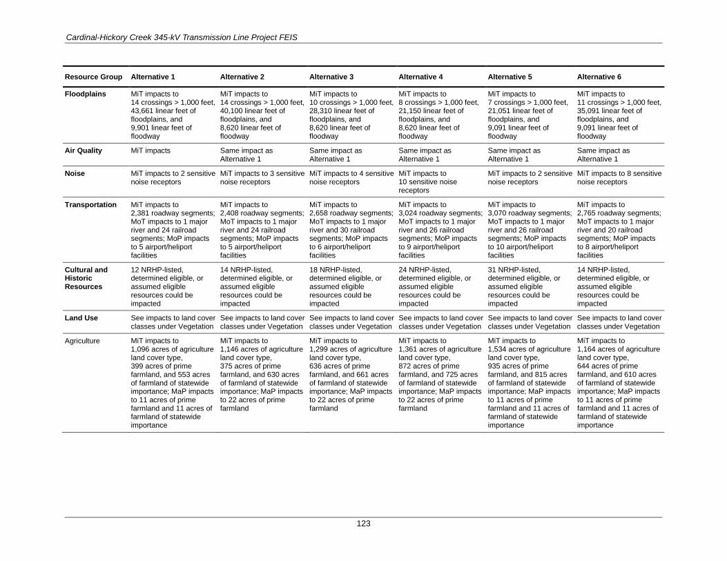
Cardinal-Hickory Creek 345-kV Transmission Line Project FEIS
123
Resource Group Alternative 1 Alternative 2 Alternative 3 Alternative 4 Alternative 5 Alternative 6
Floodplains MiT impacts to 14 crossings > 1,000 feet, 43,661 linear feet of floodplains, and 9,901 linear feet of floodway
MiT impacts to 14 crossings > 1,000 feet, 40,100 linear feet of floodplains, and 8,620 linear feet of floodway
MiT impacts to 10 crossings > 1,000 feet, 28,310 linear feet of floodplains, and 8,620 linear feet of floodway
MiT impacts to 8 crossings > 1,000 feet, 21,150 linear feet of floodplains, and 8,620 linear feet of floodway
MiT impacts to 7 crossings > 1,000 feet, 21,051 linear feet of floodplains, and 9,091 linear feet of floodway
MiT impacts to 11 crossings > 1,000 feet, 35,091 linear feet of floodplains, and 9,091 linear feet of floodway
Air Quality MiT impacts Same impact as Alternative 1
Same impact as Alternative 1
Same impact as Alternative 1
Same impact as Alternative 1
Same impact as Alternative 1
Noise MiT impacts to 2 sensitive noise receptors
MiT impacts to 3 sensitive noise receptors
MiT impacts to 4 sensitive noise receptors
MiT impacts to 10 sensitive noise receptors
MiT impacts to 2 sensitive noise receptors
MiT impacts to 8 sensitive noise receptors
Transportation MiT impacts to 2,381 roadway segments; MoT impacts to 1 major river and 24 railroad segments; MoP impacts to 5 airport/heliport facilities
MiT impacts to 2,408 roadway segments; MoT impacts to 1 major river and 24 railroad segments; MoP impacts to 5 airport/heliport facilities
MiT impacts to 2,658 roadway segments; MoT impacts to 1 major river and 30 railroad segments; MoP impacts to 6 airport/heliport facilities
MiT impacts to 3,024 roadway segments; MoT impacts to 1 major river and 26 railroad segments; MoP impacts to 9 airport/heliport facilities
MiT impacts to 3,070 roadway segments; MoT impacts to 1 major river and 26 railroad segments; MoP impacts to 10 airport/heliport facilities
MiT impacts to 2,765 roadway segments; MoT impacts to 1 major river and 20 railroad segments; MoP impacts to 8 airport/heliport facilities
Cultural and Historic Resources
12 NRHP-listed, determined eligible, or assumed eligible resources could be impacted
14 NRHP-listed, determined eligible, or assumed eligible resources could be impacted
18 NRHP-listed, determined eligible, or assumed eligible resources could be impacted
24 NRHP-listed, determined eligible, or assumed eligible resources could be impacted
31 NRHP-listed, determined eligible, or assumed eligible resources could be impacted
14 NRHP-listed, determined eligible, or assumed eligible resources could be impacted
Land Use See impacts to land cover classes under Vegetation
See impacts to land cover classes under Vegetation
See impacts to land cover classes under Vegetation
See impacts to land cover classes under Vegetation
See impacts to land cover classes under Vegetation
See impacts to land cover classes under Vegetation
Agriculture MiT impacts to 1,096 acres of agriculture land cover type, 399 acres of prime farmland, and 553 acres of farmland of statewide importance; MaP impacts to 11 acres of prime farmland and 11 acres of farmland of statewide importance
MiT impacts to 1,146 acres of agriculture land cover type, 375 acres of prime farmland, and 630 acres of farmland of statewide importance; MaP impacts to 22 acres of prime farmland
MiT impacts to 1,299 acres of agriculture land cover type, 636 acres of prime farmland, and 661 acres of farmland of statewide importance; MaP impacts to 22 acres of prime farmland
MiT impacts to 1,361 acres of agriculture land cover type, 872 acres of prime farmland, and 725 acres of farmland of statewide importance; MaP impacts to 22 acres of prime farmland
MiT impacts to 1,534 acres of agriculture land cover type, 935 acres of prime farmland, and 815 acres of farmland of statewide importance; MaP impacts to 11 acres of prime farmland and 11 acres of farmland of statewide importance
MiT impacts to 1,164 acres of agriculture land cover type, 644 acres of prime farmland, and 610 acres of farmland of statewide importance; MaP impacts to 11 acres of prime farmland and 11 acres of farmland of statewide importance

Cardinal-Hickory Creek 345-kV Transmission Line Project FEIS
124
Resource Group Alternative 1 Alternative 2 Alternative 3 Alternative 4 Alternative 5 Alternative 6
Recreation MiT impacts to 4 recreational areas and MoT impacts to 1 recreational area; MiP impacts to 1 recreational area and MoP impacts to 2 recreational areas
MiT impacts to 4 recreational areas and MoT impacts to 1 recreational area; MiP impacts to 2 recreational areas and MoP impacts to 1 recreational area
MiT impacts to 5 recreational areas and MoT impacts to 1 recreational area; MiP impacts to 1 recreational area and MoP impacts to 2 recreational areas
MiT impacts to 4 recreational areas and MoT impacts to 1 recreational area; MoP impacts to 3 recreational areas
MiT impacts to 3 recreational areas and MoT impacts to 2 recreational areas; MoP impacts to 4 recreational areas
MiT impacts to 2 recreational areas and MoT impacts to 2 recreational areas; MiP impacts to 1 recreational area and MoP impacts to 3 recreational areas
Visual Quality and Aesthetics
MiP impacts at the overall project level; MaP impacts to 2 residences; MaP impacts, as well as beneficial impacts to the Refuge; MiP impacts to the Great River Road National Scenic Byway
MiP impacts at the overall project level; MaP impacts to 2 residences; MiP impacts to the Refuge; MaP impacts to the Great River Road National Scenic Byway
MiP impacts at the overall project level; MaP impacts to 3 residences; MiP impacts to the Refuge; MaP impacts to the Great River Road National Scenic Byway
MiP impacts at the overall project level; MaP impacts to 9 residences; MiP impacts to the Refuge; MaP impacts to the Great River Road National Scenic Byway
MiP impacts at the overall project level; MaP impacts to 2 residences; MaP impacts, as well as beneficial impacts to the Refuge; MiP impacts to the Great River Road National Scenic Byway
MiP impacts at the overall project level; MaP impacts to 8 residences; MaP impacts, as well as beneficial impacts to the Refuge; MiP impacts to the Great River Road National Scenic Byway
Socioeconomics MiT positive impacts to employment and income with $480,937,254 of temporary spending and $948,105 annual spending; MoT and MiP impacts to property values for 2 residences
MiT positive impacts to employment and income with $494,675,522 of temporary spending and $954,541 annual spending; MoT and MiP impacts to property values for 2 residences
MiT positive impacts to employment and income with $544,948,945 of temporary spending and $1,119,447 annual spending; MoT and MiP impacts to property values for 3 residences
MiT positive impacts to employment and income with $557,603,250 of temporary spending and $1,154,985 annual spending; MoT and MiP impacts to property values for 9 residences
MiT positive impacts to employment and income with $568,612,262 of temporary spending and $1,210,366 annual spending; MoT and MiP impacts to property values for 2 residences
MiT positive impacts to employment and income with $490,301,721 of temporary spending and $844,933 annual spending; MoT and MiP impacts to property values for 8 residences
Environmental Justice Communities
MoT and MoP impacts to 2 communities with potential environmental justice populations
MoT and MoP impacts to 1 community with potential environmental justice populations
MoT and MoP impacts to 2 communities with potential environmental justice populations
MoT and MoP impacts to 3 communities with potential environmental justice populations
MoT and MoP impacts to 4 communities with potential environmental justice populations
MoT and MoP impacts to 3 communities with potential environmental justice populations
Public Health and Safety
MiP exposure to electric and magnetic fields (EMF) for 2 residences
MiP exposure to EMF for 1 school and 2 residences
MiP exposure to EMF for 1 school and 3 residences
MiP exposure to EMF for 1 school and 9 residences
MiP exposure to EMF for 2 residences
MiP exposure to EMF for 8 residences

Cardinal-Hickory Creek 345-kV Transmission Line Project FEIS
125
Resource Group Alternative 1 Alternative 2 Alternative 3 Alternative 4 Alternative 5 Alternative 6
The Refuge Segment B-IA1 39 acres of ROW within the Refuge; Permanent impacts to 23 acres of the Turkey River restoration area, 0.1 acre of wetlands, and 0 acres of forest removal within ROW; Restoration of 14 acres of the existing 161-kV transmission line ROW
46 acres of ROW within the Refuge; Permanent impacts to 0 acres in the Turkey River restoration area, 12 acres of forested wetlands, and 46 acres of non-forested wetland within ROW
Same impact as Alternative 2
Same impact as Alternative 2
Same impact as Alternative 1
Same impact as Alternative 1
Segment B-IA2 44 acres of ROW within the Refuge; Permanent impacts 27 acres in the Turkey River restoration area, 1 acre of wetlands, and 1 acre of forest removal within ROW; Restoration of 14 acres of the existing 161-kV transmission line ROW

Cardinal-Hickory Creek 345-kV Transmission Line Project FEIS
126
2.6 AGENCY PREFERRED ALTERNATIVE NEPA requires the lead Federal agency to identify a preferred alternative in the FEIS. Due to the complexity of the C-HC Project and other Federal agency involvement in the development of this FEIS and permitting process, RUS consulted and coordinated with the USACE and USFWS through the preferred alternative selection process. RUS identified Alternative 6 as the Agency Preferred Alternative for the C-HC Project. The agency preferred alternative is described in detail in FEIS Section 2.3.2.6 and shown in Figure 2.3-12 and Figure 2.3-13. Alternative 6 was selected as the Agency Preferred Alternative because it would:
• use existing and proposed linear ROWs by paralleling existing and proposed infrastructure and transmission lines;
• minimize and mitigate habitat fragmentation and resource impacts within the Refuge, when compared to other alternatives for crossing the Refuge;
• reduce impacts to resources that are regulated by other laws, including the Endangered Species Act, National Historic Preservation Act, Clean Air Act, Clean Water Act, Farmland Protection Policy Act, and Executive Order 11988: Floodplain Management;
• reduce impacts to resources that were raised by numerous comments from the public, such as potential impacts to forested areas, property values, and public health and safety; and
• align with the route ordered by the PSCW on September 26, 2019 as part of the decision to issue the CPCN for the C-HC Project in Wisconsin.
Alternative 6 strikes the balance between reducing impacts to resources while also maintaining consistency with the state regulatory process for reviewing and approving transmission projects and issuing CPCNs in Wisconsin. It is important to note that the state regulatory process for reviewing the C-HC Project in Iowa is not scheduled for conclusion until early 2020.
RUS also identified Alternatives 1 and 5 as suitable alternatives for balancing the needs of the Proposed Action while also addressing resource impacts and mitigating habitat fragmentation within the Refuge. The preferred and other suitable alternatives are consistent with the purpose and need as described in FEIS Chapter 1 and are in compliance with applicable laws and regulations. FEIS Section 2.5 provides a full comparison of impacts among the action alternatives analyzed in detail in this FEIS.
The USFWS does not have a preferred alternative for crossing the Refuge, however, all segments that would cross the Refuge were developed in coordination with the USFWS, with the goal of reducing habitat fragmentation and resource impacts within the Refuge.
The USFWS and the USACE have received applications from the Utilities for a ROW permit. The route through the Refuge proposed in the ROW permit application has been evaluated through a Refuge compatibility determination (see Appendix J) which is available for public comment with the same comment deadline as this FEIS.
The identification of the Agency Preferred Alternative and other suitable alternatives is dependent on the Utilities implementing all mitigation measures outlined in FEIS Chapter 3, Appendix I, and the ROW permit(s) from the USFWS and USACE for the portion of the C-HC Project that crosses the Refuge.

Cardinal-Hickory Creek 345-kV Transmission Line Project FEIS
127
2.7 ENVIRONMENTALLY PREFERABLE ALTERNATIVE The Environmentally Preferable Alternative is the alternative that will promote the national environmental policy as expressed in Section 101(B) of NEPA. This means that the Environmentally Preferable Alternative is the “alternative that causes the least damage to the biological and physical environment; it also means that alternative which best protects, preserves, and enhances historic, cultural, and natural resources” (CEQ 1981:Question 6a). To determine the Environmentally Preferable Alternative, RUS considered the results of the environmental analyses presented in FEIS Chapter 3. Each alternative was evaluated in terms of potential adverse environmental impacts.
While RUS is required to identify an Environmentally Preferable Alternative in the record of decision, the agency is not required to select the Environmentally Preferable Alternative as the Agency Preferred Alternative for analysis or in their decision. For the Environmentally Preferable Alternative, action alternatives were evaluated according to the nature and magnitude of their environmental consequences.
The Environmentally Preferable Alternative for the C-HC Project is Alternative 5. The potential impacts to resources resulting from Alternative 5 would be the least, when considering impacts to all resources analyzed in FEIS Chapter 3. Alternative 5 is described in detail in FEIS Section 2.3.2.5 and shown in Figure 2.3-10 and Figure 2.3-11. FEIS Section 2.5 provides a full comparison of impacts among the action alternatives analyzed in detail in this FEIS.