Robison Park – Sorenson BOLD™ 345-kV Transmission Line · PDF fileBOLD™...
8
Execuve Summary Robison Park – Sorenson BOLD™ 345-kV Transmission Line Project At a me when both the expectaons of the industry and those of the public are changing, modernizing the electric grid is a significant challenge. Today, more than ever before, the grid needs to be dynamic and adaptable. A changing generaon porolio and increasingly engaged landowners and sing boards are challenging transmission developers and the system as never before. To address these changing expecta- ons, AEP engineers designed an innovave soluon — a new concept line design delivering more capac- ity and efficiency in a compact, aesthec form. Breakthrough Overhead Line Design (BOLD) is the first transformaonal line design the industry has experienced in almost 50 years. With an inial deployment energized in 2016, BOLD moved rapidly from concept to exceeding its performance expectaons in just five years. © 2017 American Electric Power. All Rights Reserved
Transcript of Robison Park – Sorenson BOLD™ 345-kV Transmission Line · PDF fileBOLD™...
Executive Summary
Robison Park – Sorenson BOLD™ 345-kV Transmission Line Project
At a time when both the expectations of the industry and those of the public are changing, modernizing the electric grid is a significant challenge. Today, more than ever before, the grid needs to be dynamic and adaptable. A changing generation portfolio and increasingly engaged landowners and siting boards are challenging transmission developers and the system as never before. To address these changing expecta-tions, AEP engineers designed an innovative solution — a new concept line design delivering more capac-ity and efficiency in a compact, aesthetic form. Breakthrough Overhead Line Design (BOLD) is the first transformational line design the industry has experienced in almost 50 years. With an initial deployment energized in 2016, BOLD moved rapidly from concept to exceeding its performance expectations in just five years.
© 2017 American Electric Power. All Rights Reserved
Beginnings of BOLDThe BOLD story began when a team of engineers at AEP were challenged to push the innovation envelop and develop a transformative improve-ment in the way we delivery energy. The driver for this innovative transformation is the need to modernize the electric grid at a time when both the expectations of the system itself and those of the public are changing. Public interest in re-newable energy requires a robust, efficient grid to move the energy from remote areas to the load centers. Aging Infrastructure needs to be renewed, enhanced or rethought. Crowded util-ity corridors allow little room for expansion, and there are limited opportunities for new urban corridors. And finally, there is a general public re-sistance to new overhead transmission lines, es-pecially the highest transmission voltages.
So there was the challenge: Develop a solution that is high-capacity, high-efficiency, cost-effec-tive, and enhances public acceptance. With this objec-tive, AEP engineers focused on how to creatively re-shape the physics of our traditional design to deliver the desired improvements utilizing fewer right-of-way cor-ridors. And to enhance public acceptance during siting, the new design also needed to leave a more appealing visual impression than traditional options offer.
The result of this engineering effort is the now patented Breakthrough Overhead Line Design (BOLD) technology. By re-imagining the spatial, geometric and material as-pects of line design, AEP was able to leverage physics to produce a transformative improvement in electric perfor-
mance to previously unachieved levels for an Extra-High Voltage (EHV) line. BOLD’s compact “delta” configuration along with the expanded bundle design (conductor diam-eter, size, and number of subconductors) are optimized for maximum performance.
The electrical benefit of this configuration is a line with reduced inductance and increased capacitance. This re-sults in higher Surge Impedance Loading (SIL), a mea-sure of the relative loadabilty among line designs, along with lower line losses, and a 50% reduction in ground-level magnetic field levels compared to traditional line designs of the same voltage. By way of comparison, a double-circuit 345-kV BOLD line could provide a com-
bined SIL 32% higher than a typical 500-kV line using the same conductor bundle in less right-of-way. The BOLD line design, in other words, safely allows the industry to move larger blocks of power without the added cost and complexity of the necessity of a higher voltage class or utilizing series compensation devices.
The compact delta design not only gives BOLD its enhanced electrical performance but also enables the use of the simple, el-egant, low-profile arch design. This unique arch supports the two compact circuits, as well as the optical ground wires (OPGW). The OPGW configuration carries the line’s two fiber-optic communications paths and
2
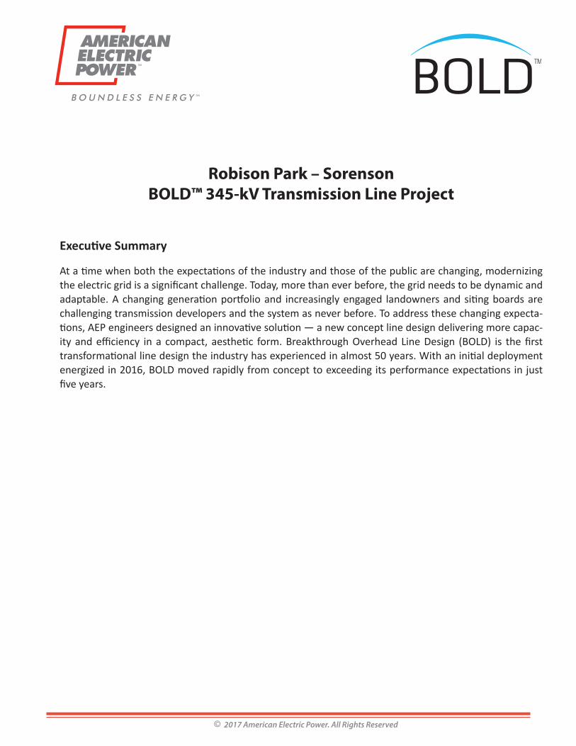
Calculation showing the relationship between SIL and line geometry
Utility customers prefer BOLD’s aesthetics to traditional transmission structures.
© 2017 American Electric Power. All Rights Reserved

is able to achieve a zero-degree shield angle, providing maximum protection from lightning strikes. The mod-ernized design also minimizes the structure height, with the average 100-foot, 345-kV BOLD structure about one-third shorter than a traditional double-circuit design. BOLD’s streamlined profile and compact line configura-tion is well suited for constrained corridors, making it an excellent option for populated areas that have significant loads but limited space.
In a 2015 survey, utility customers found BOLD’s cres-cent-shaped, lower height structure to be preferable to more traditional transmission towers.
The result is a transmission line that achieves an unusual synergy between form and function, offering intrinsically higher capability and improved efficiency with a simple, elegant, low-profile design that produces a softer visual impact.
Industry Partners Help Prepare BOLD for ImplementationWith BOLD elevating compact line design to new levels, exhaustive analyses and extensive structural and electri-cal laboratory testing were required to confirm its ca-pabilities before it could be deployed in the field. AEP teamed with industry leaders to validate that the new line design met rigorous performance requirements and would have the requisite structures, insulators, and hardware ready for practical installation. Several of these tests were “firsts” for AEP and its partners, showing just how rare it is to see such a significant departure from convention.
• Manitoba HVDC Research Centre (MHRC) assisted AEP in insulation coordination studies to determine the desirable insulation strength including over volt-age control methods by simulating thousands of sys-tem conditions.
• AEP and Electric Power Research Institute (EPRI) en-gineers joined to complete comprehensive electrical testing at EPRI’s Power Delivery Laboratory in Lenox, Massachusetts. The high-voltage testing was com-pleted to establish the air gap electrical strengths to ensure it is larger than the requirement established from the insulation coordination study. A full-scale BOLD structure was installed to represent the true ground plan for the three-phase conductor in order to test audible noise, power frequency, lightning, and switching impulse testing for the insulator as-
semblies. The three-phase testing ultimately con-firmed that the line performance in corona, audible noise, lightning, and switching met or exceeded the design criteria and that the insulator assemblies, tower grounding, and terminal equipment were op-timized to minimize construction costs.
• AEP established the conductor-motion study crite-ria by calibrating the industry standards with our ex-tensive field operation experience, and performed in-house studies and developed a mitigation plan to limit the possibility of unexpected conductor move-ment, which can lead to flashovers, breaker opera-tions, and overloading of structural and electrical components under various conductor motion types (galloping, wake-induced oscillations, gust response differential, ice shedding, fault current, unequal ice sag differential) and weather conditions.
• Hubbell Power Systems (HPS) worked jointly with AEP in determining the electrical field grading and insulation requirements for the insulator assembly design. AEP and HPS engineers established the me-chanical and electrical design parameters and set test requirements for the tangent, running angle, and dead-end insulator assemblies. Single-phase power-frequency testing was completed at HPS’s Wadsworth Test Facility and confirmed that the in-sulator assemblies met or exceeded the electrical performance requirements.
Robison Park – Sorenson BOLD™ 345-kV Transmission Line Project
3
EPRI electrical test setup for BOLD
© 2017 American Electric Power. All Rights Reserved
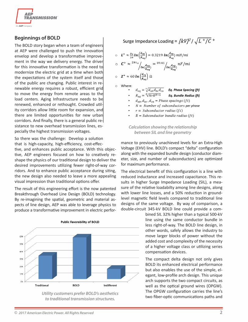
• AEP and Valmont jointly refined the structure de-sign for the installation to maintain its streamlined, curved-beam appearance, using the tapered arm shafts and knuckle connections. The tapered steel shaft bending, using an induction heating process, was another first for the industry. Valmont Industries fabricated the tubular-steel structure and collabo-
rated with BendTech to develop the tapered-shaft bending process and the material specification. AEP and Valmont, with assistance from EWI, collabora-tively investigated the fatigue performance of the welded-arm base connections to ensure they are fa-tigue free from vortex-induced vibration. Full-scale structural testing including the real insulator assem-blies was conducted at the Valmont-Newmark test-ing facility in Valley, Nebraska to confirm the integ-rity of the structure under various extreme weather conditions and the load path on the interconnected insulator assemblies for the insulator design.
• Both constructability and line maintenance were heavily considered in BOLD structure and insulator assembly development. PAR Electrical Contractors Inc., a Quanta Services company, was integrally in-volved in the development of construction means and methods for BOLD, as well as serving as the primary construction contractor on the first BOLD line project. AEP also constructed a BOLD structure in its transmission training center to assist the AEP field services organization in developing the means and methods for de-energized maintenance and the evaluation of new approaches for energized mainte-nance.
Studies and test results substantiated that the BOLD de-sign delivered on its predicted performance, and that it presented an ideal solution to an emerging situation on the AEP system.
An Extraordinary Reliability Challenge As early as 2010, PJM (a regional transmission organiza-tion that covers 13 states plus the District of Columbia, and of which AEP is a member) identified widespread low-voltage conditions and multiple line overloads in the Fort Wayne, Indiana area as part of its annual Regional Transmission Expansion Planning (RTEP) process. The area, in addition to being the largest metropolitan area in the AEP Indiana Michigan Power Company’s service territory with around 3,000 MW of peak load, also sits at a vital crossroads of EHV transmission within the PJM region and routinely shoulders heavy power flows be-tween PJM and MISO.
In an unprecedented turn of events, the reliability threat intensified following the announcement that nearly 14 GW of fossil generation would be retired in PJM due to environmental regulations. While typical transmission projects are planned at least five years in advance, these events exacerbated the already significant reliability chal-lenge in Fort Wayne and necessitated that it be resolved in less than three.
In response, AEP developed a twofold solution to resolve these issues. First, a new 765-kV source was introduced to the existing Sorenson 345-kV substation on the south-
4
Curved cross arms await deployment.
Map of the project area
© 2017 American Electric Power. All Rights Reserved

west side of Fort Wayne. The expanded station would now act as a source of both real and reactive power into the area, and thus strengthen the system and relieve voltage concerns.
Because the new 765-kV source increased power flows on the underlying 345-kV and 138-kV lines, some of which were already overloaded, AEP also needed to strengthen the surrounding system. A new 345-kV line needed to be built around the Fort Wayne metro area. Given the time constraints, the best choice was to re-build and upgrade an existing 138-kV corridor to deliver 345-kV capacity. This new higher voltage line needed to be constructed within an existing and mostly suburban right-of-way. In the absence of a formal siting process in Indiana, AEP had to assure state and local agencies, municipalities and townships, and individual landown-ers that the project was essential, beneficial, and would have minimal negative impact to the aesthetics of their community.
A BOLD SolutionWith the accelerated timeline in Fort Wayne, AEP engi-neers proposed applying BOLD technology to rebuild the existing 1940’s vintage Robison Park – Sorenson 138-kV line as a double-circuit line, with one circuit operating at 345 kV and the other circuit at 138 kV. This option allowed for a high capacity 345-kV path (up to 5000 amps) around Fort Wayne without affecting the local distribution sta-tions along the existing 138-kV path. Even with one circuit operating at 138-kV, the new BOLD line’s capacity would enable five times the megawatts to flow within the same corridor. The reduced line impedance and increased line charging provided by BOLD would also deliver additional voltage support in the area and approximately 33 percent lower line losses compared with typical 345-kV and 138-kV designs.
BOLD’s compact design and appealing visual impact made installation of a higher voltage line within an exist-ing lower-voltage right-of-way more practical compared to a conventional 345-kV double-circuit line, which would have been up to 50 feet taller. This proved ad-vantageous in meeting the aggressive schedule because the route traverses several heavily developed and estab-lished commercial and residential areas. Many sections of the right-of-way corridor left little room for expansion.
AEP held several open houses in the area to discuss the project with affected residents and businesses. They expressed positive feedback on the BOLD option (com-
Robison Park – Sorenson BOLD™ 345-kV Transmission Line Project
5
Example of constraints along the existing line corridor
The upgraded line runs through several suburban developments.
© 2017 American Electric Power. All Rights Reserved
pared to the conventional design) in spite of reservations about construction of a new high voltage line in their backyards.
BOLD Goes LiveThe many unknowns associated with this first-of-its-kind technology (indeed, with every new technology) required the project team to have confidence in the engineering, design, and testing capabilities of AEP and its partners. Though not unique to the BOLD design, several challenges were considered prior to the start of construction. The project faced significant outage con-straints, which limited construction activities to off-peak periods. Expected wet weather, various environmental conditions, and close proximity to homes and business-es required careful planning for material logistics, foun-dation design, construction activity, and, above all, com-munication. Construction officially began in the spring of 2014.
Beyond these challenges, installation proved very effi-cient since construction considerations were integral to the design process. A special vang added during the de-sign allowed the approximately 8,000 lb curved arm to be picked with ease. Extra attachment points were provided along the length of the poles to allow multiple options for the guying the arms down to mitigate wind-induced vibration concerns. Eventually, it was determined that hanging the arm with two of the insulator assemblies pre-mounted was an even more efficient method.
After the structures were erected and the assemblies installed, conductor was strung and sagged using tradi-tional methods and equipment. Clipping in the conduc-tor to the tangent assemblies required some additional rigging on the lower two phases, and extra rigging points that were designed into the arm allowed for these extra steps without adding time to the process. Although the conductor was strung and sagged without the need for specialty equipment or methods, the OPGW required a
6
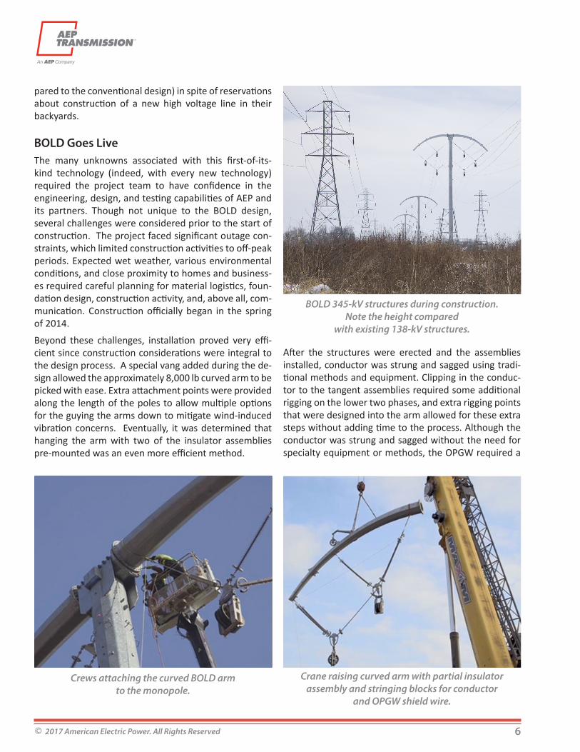
Crane raising curved arm with partial insulator assembly and stringing blocks for conductor
and OPGW shield wire.
Crews attaching the curved BOLD arm to the monopole.
BOLD 345-kV structures during construction. Note the height compared
with existing 138-kV structures.
© 2017 American Electric Power. All Rights Reserved

specialty stringing arm to install the wire on top of the arch. After stringing and sagging was completed, the arms were removed as the shield wire was clipped in. The stringing arm attachment points were considered during the arm design and it fulfilled this purpose well.
In the end, project execution proved safe and successful, with the new BOLD line between Robison Park and So-
renson stations being placed into full service on Novem-ber 14, 2016. That event resulted from the hard work of many professionals who took a new concept from test-ing in a laboratory to energizing the first line in just three years.
With the BOLD line now energized, AEP has turned it into a working laboratory. An autonomous field monitoring
Robison Park – Sorenson BOLD™ 345-kV Transmission Line Project
7
Image of corona discharge using CoroCAM 6D, part of the audible noise monitoring system
Power flows across BOLD 345-kV line since energization
EPRI monitoring system for BOLD line.
© 2017 American Electric Power. All Rights Reserved

system has been installed on the line to monitor on-going operating conditions and confirm engineering calcula-tions. The field monitoring system captures data on the curved beam tip motion, top of pole movement, conduc-tor motion, current leakage across insulators and stress ranges at critical welded-joint locations, along with local weather conditions.
Individual RF sensors, developed and provided by EPRI, monitor each component. The sensors collect data on conductor temperature, current, and movement in five-minute intervals. Additional monitoring has also been installed along the line right-of-way to capture audible noise and EMF values. AEP will study the data captured from the sensing systems to determine the line’s re-sponse to various stresses, performance under different conditions, as well as validating calculated performance
criteria. This information will be used to further enhance future BOLD designs, expand their capabilities, and pro-vide insights for applications in different environments.
Based on data captured to date, the line is meeting or exceeding expectations. OMICRON-assisted imped-ance testing confirmed that the line’s actual positive-sequence impedance (and associated SIL) is within <3% of the calculated values, proving that the engineering concepts work. Audible noise and EMF values are also measuring below calculated limits.
Above all, the line is showing its importance as power flows on the line have continuously increased since it was energized despite very mild weather. It is anticipat-ed that this line will play a vital role in regional reliability as we approach the summer season.
Looking AheadBOLD has crossed the threshold from concept to prov-en design with the first commercial application of the patented design in the world. It demonstrates how in-novative, breakthrough technology can deliver practical solutions for the industry and meet the expectations of landowners. Additional projects are planned or under consideration in Ohio and Texas, and, demonstrating flexibility in tower design, a new BOLD line using lattice structures is being built near Lafayette, Indiana.
This technology is particularly suit-ed to interconnect renewable re-sources and transport their capac-ity long distances. In the past, only transmission lines designed for op-eration at the highest voltages, and/or equipped with external compen-sation, were available for long-dis-tance, bulk power deliveries. Today, transmission owners and develop-ers have more options with a line design that minimizes the right-of-way footprint, noise, and EMF as it provides an aesthetic appearance and reduced tower height, easing the challenges of siting new trans-mission lines and rebuilding existing infrastructure.
In 2015, AEP launched BOLD Trans-mission, LLC, as a vehicle offering this technology to de-velopers both nationally and internationally. With the success of this first project, AEP is driven to employ BOLD elsewhere within its footprint and across the industry.
8
AEP’s Robison Park - Sorenson Line, Indiana
© 2017 American Electric Power. All Rights Reserved