Canon Mvx250i Mvx200i e Sm
259
No. D17-8216, 8233 D17-8236 Digital Video Camera CANON INC. 2004 Canon Inc. Digital Imaging Products Service Dept. First Edition : Mar. 2004 First Print : Mar. 2004 Video Product c MVX250i E MVX200i E MVX200 E MVX250i E MVX200i E MVX200 E iPAL
description
Canon Mvx250i Mvx200i service manual
Transcript of Canon Mvx250i Mvx200i e Sm
No. D17-8216, 8233D17-8236
Digital Video Camera
CANON INC. 2004
Canon Inc.Digital Imaging Products Service Dept.
First Edition : Mar. 2004First Print : Mar. 2004
Video Product
c
MVX250i EMVX200i EMVX200 E
MVX250i EMVX200i EMVX200 E
iPAL

GENERAL DESCRIPTION OF PRODUCT
CONTENTS
1. Product Overview -------------------------------------------------------------------------------------------------------------------------------- 1
1-1 Main Features ----------------------------------------------------------------------------------------------------------------------------- 1
1-1-1 Easy Direct Button ------------------------------------------------------------------------------------------------------------ 1
1-1-2 DV Messenger 2 --------------------------------------------------------------------------------------------------------------- 2
1-2 Product Specifications Comparison Chart -------------------------------------------------------------------------------------------- 3
1-3 Function and Performance List --------------------------------------------------------------------------------------------------------- 4
2. Technical Explanation ------------------------------------------------------------------------------------------------------------------------- 10
2-1 Design ----------------------------------------------------------------------------------------------------------------------------------- 10
2-1-1 Design Concept-1 ----------------------------------------------------------------------------------------------------------- 10
2-1-2 Design Concept-2 ----------------------------------------------------------------------------------------------------------- 10
2-1-3 Differences in Appearance of Overseas Models MVX250i E, MVX200i E, MVX200 E ------------------------ 11
2-2 18× zoom lens -------------------------------------------------------------------------------------------------------------------------- 12
2-2-1 Features of 18× lens -------------------------------------------------------------------------------------------------------- 12
2-2-2 New technologies and new functions ------------------------------------------------------------------------------------- 12
2-3 Easy Direct Button ([ ] Print/Share button) ------------------------------------------------------------------------------ 13
2-3-1 Direct Print function -------------------------------------------------------------------------------------------------------- 13
2-3-2 Direct Transfer --------------------------------------------------------------------------------------------------------------- 14
2-3-2-1 Startup ------------------------------------------------------------------------------------------------------------ 15
2-3-2-2 ALL IMAGES ---------------------------------------------------------------------------------------------- 16
2-3-2-3 NEW IMAGES --------------------------------------------------------------------------------------------- 17
2-3-2-4 TRANSFER ORDERS------------------------------------------------------------------------------------ 18
2-3-2-5 SELECT & TRANSFER --------------------------------------------------------------------------------- 19
2-3-2-6 WALL PAPER ---------------------------------------------------------------------------------------------- 20
3. Performance ------------------------------------------------------------------------------------------------------------------------------------- 21
4. System Diagram (Common to all Models) -------------------------------------------------------------------------------------------------- 35
5. Overview of viewfinder / LCD panel displays --------------------------------------------------------------------------------------------- 36
5-1 Camera mode --------------------------------------------------------------------------------------------------------------------------- 36
5-2 VCR mode ------------------------------------------------------------------------------------------------------------------------------ 43
5-3 Card / Camera mode ------------------------------------------------------------------------------------------------------------------- 47
5-4 Card Playback mode ------------------------------------------------------------------------------------------------------------------- 50
5-4-1 Still image Playback -------------------------------------------------------------------------------------------------------- 50
5-4-2 Motion video (Motion JPEG) Playback ---------------------------------------------------------------------------------- 51
5-4-3 Direct printing --------------------------------------------------------------------------------------------------------------- 52
5-5 Menu Display --------------------------------------------------------------------------------------------------------------------------- 53
5-6 Card-related screen displays ---------------------------------------------------------------------------------------------------------- 64
5-7 Direct print setting screen ------------------------------------------------------------------------------------------------------------- 71
5-8 Print designations ---------------------------------------------------------------------------------------------------------------------- 76
5-9 Warning displays ----------------------------------------------------------------------------------------------------------------------- 77
MVX250i E, MVX200i E, MVX200 EGENERAL DESCRIPTION OF PRODUCT
1
1. Product Overview
1-1 Main Features
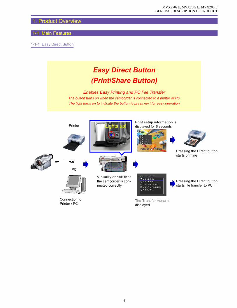
1-1-1 Easy Direct Button
Easy Direct Button
(Print/Share Button)
Enables Easy Printing and PC File TransferThe button turns on when the camcorder is connected to a printer or PC
The light turns on to indicate the button to press next for easy operation
Printer
PC
Connection to Printer / PC
Lights up!
Visually check that the camcorder is con-nected correctly
Print setup information is displayed for 6 seconds
Pressing the Direct button starts printing
Pressing the Direct button starts file transfer to PC
The Transfer menu is displayed

MVX250i E, MVX200i E, MVX200 EGENERAL DESCRIPTION OF PRODUCT
2
1-1-2 DV Messenger 2
A peer-to-peer (P2P) type bidirectional communications software using DV (Digital Video Camcorder)
Allows bidirectional sending of audio/video content and messages (text/images) via the Internet.
Basic specifications are compatible with Windows Messenger.
Allows control (camera zoom and focus, VCR playback and stop, access to the memory card) of the digital video camcorder
from a remote PC.
Remote home monitoring camera using the web camera function (enables monitoring of your home from a remote location)
IEEE1394 IEEE1394Internet

MVX250i E, MVX200i E, MVX200 EGENERAL DESCRIPTION OF PRODUCT
3
1-2 Product Specifications Comparison Chart
*1 : Not applicable to MVX200 E
Specifications MVX250i E MVX200i E, MVX200 E
Zoom mag. Tape optical 18× / digital 360× optical 14× / digital 280×
Card optical 18× / digital 72× optical 14× / digital 56×
CCD 1/4.5-inch interlaced CCD (Total pixels : Approx. 1.33 megapixels)
(Effective pixels Tape motion video : Approx. 860,000 pixels
Card still image: Approx. 1,230,000 pixels)
Image stabilizer Electronic image stabilizer (during tape mode only)
Monitor 2.5-inch 123,000 pixel LCD monitor
EVF 0.33-inch 113,000 pixel color viewfinder
Memory card function (SD memory card, MultiMediaCard)
Card Still images Progressive Photo
recording (1024×768, 640×480)
Card motion videoAVI (Video data: Motion JPEG / Audio data: WAVE (monaural))
recording
USB file transfer
Direct print (Support for Direct Print, Bubble Jet Direct, and PictBridge)
File transfer IEEE1394 / USB
Streaming IEEE1394
USB compatibility (USB 2.0 Full Speed class with PTP support)
Accessory shoe (Advanced accessory shoe not supported)
Auxiliary illumination White LED (Night+ : always on)
function (Super Night : Lights in accordance ×
with brightness)
Night mode (Night, Night+, Super Night) (Night)
High-resolution 16:9 (Letterbox display)
END search
S-Video terminal
DV, analog line inputs
Microphone terminal × *1
Wide attachment lens×
supplied
Remote controller
supplied battery NB-2LH (MVX250i E only is supplied with BP-2L14)

MVX250i E, MVX200i E, MVX200 EGENERAL DESCRIPTION OF PRODUCT
4
1-3 Function and Performance List
Item MVX250i E, MVX200i E, MVX200 E
Camera
Image sensing Image size 1/4.5-inch CCD
device System (filter) Interlacing (color correction filter)
Total pixels Approx. 1.33 megapixels
Effective pixels Tape Approx. 860,000 pixels
Card Approx. 1,230,000 pixels
Lens Optical zoom magnification, Tape MVX250i E : 18× 3.5 to 63 mm (Approx. 45.4 to 817.2 mm)
focal length MVX200i E, MVX200 E : 14× 3.5 to 49 mm (Approx. 45.4 to 635.6 mm)
(35mm equivalent) Card MVX250i E : 18× 3.5 to 63 mm (Approx. 37.9 to 682.2 mm)
MVX200i E, MVX200 E : 14× 3.5 to 49 mm (Approx. 37.9 to 530.6 mm)
Digital zoom Magnification Tape MVX250i E : 72× / 360× 252 mm / 1,260 mm
magnification (Approx. 3,269 mm / 16,344 mm equivalent)
focal length MVX200i E, MVX200 E : 56× / 280× 196 mm / 980 mm
(35mm equivalent) (Approx. 2,542 mm / 12,712 mm equivalent)
Card MVX250i E : 72× Approx. 252 mm (Approx. 2,728.8 mm equivalent)
MVX200i E, MVX200 E : 56× Approx. 196 mm
(Approx. 2,122.4 mm equivalent)
System Tape CCD readout
Card CCD readout
F number Tape MVX250i E : F1.8 to 3.4
MVX200i E, MVX200 E : F1.8 to 3.1
Card MVX250i E : F1.8 to 3.4
MVX200i E, MVX200 E : F1.8 to 3.1
Aperture leaves (Number of leaves) 2 leaves
Zoom speed Variable
Filter diameter 34mm P0.5
Noise reduction Camera Tape Either CCD-NR or Y/C-NR
Card None
Chroma-only, median filter
Recorder C-NR system
Minimum Night mode 1.5 lx
illumination Low Light mode 3.0 lx
Auto mode(when auto slow shutter is selected) 6.0 lx
Image Image stabilization system Tape Electronic system
stabilization Card None
Sensing method Angular velocity sensing
MotionvideoStillimage
MVX250i E, MVX200i E, MVX200 EGENERAL DESCRIPTION OF PRODUCT
5
Item MVX250i E, MVX200i E, MVX200 E
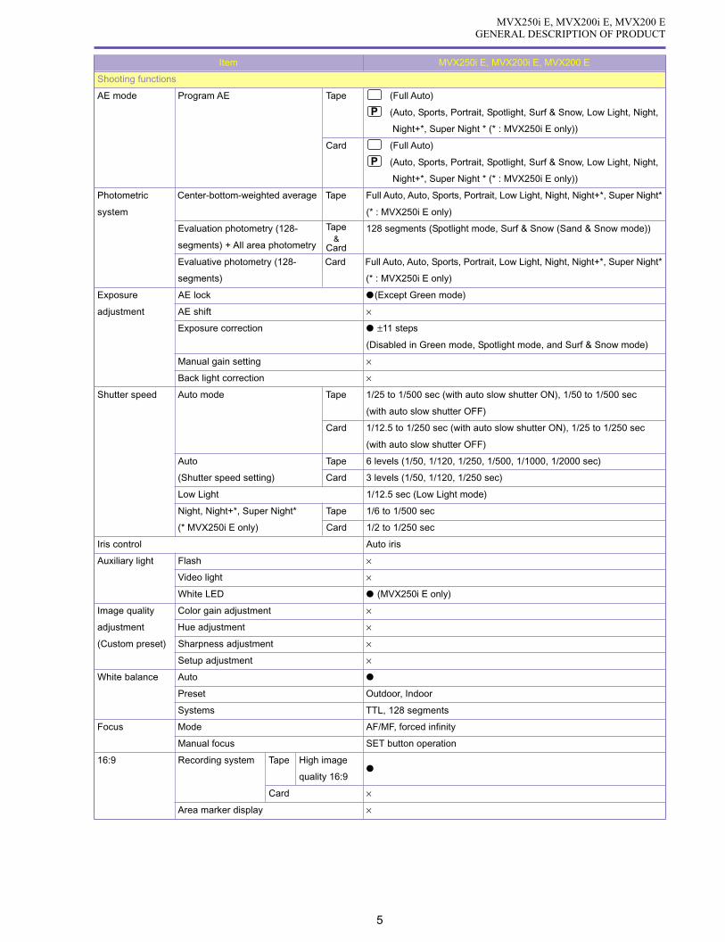
Shooting functions
AE mode Program AE Tape (Full Auto)
(Auto, Sports, Portrait, Spotlight, Surf & Snow, Low Light, Night,
Night+*, Super Night * (* : MVX250i E only))
Card (Full Auto)
(Auto, Sports, Portrait, Spotlight, Surf & Snow, Low Light, Night,
Night+*, Super Night * (* : MVX250i E only))
Photometric Center-bottom-weighted average Tape Full Auto, Auto, Sports, Portrait, Low Light, Night, Night+*, Super Night*
system (* : MVX250i E only)
Evaluation photometry (128- Tape 128 segments (Spotlight mode, Surf & Snow (Sand & Snow mode))
segments) + All area photometry Card
Evaluative photometry (128- Card Full Auto, Auto, Sports, Portrait, Low Light, Night, Night+*, Super Night*
segments) (* : MVX250i E only)
Exposure AE lock (Except Green mode)
adjustment AE shift ×
Exposure correction ±11 steps
(Disabled in Green mode, Spotlight mode, and Surf & Snow mode)
Manual gain setting ×
Back light correction ×
Shutter speed Auto mode Tape 1/25 to 1/500 sec (with auto slow shutter ON), 1/50 to 1/500 sec
(with auto slow shutter OFF)
Card 1/12.5 to 1/250 sec (with auto slow shutter ON), 1/25 to 1/250 sec
(with auto slow shutter OFF)
Auto Tape 6 levels (1/50, 1/120, 1/250, 1/500, 1/1000, 1/2000 sec)
(Shutter speed setting) Card 3 levels (1/50, 1/120, 1/250 sec)
Low Light 1/12.5 sec (Low Light mode)
Night, Night+*, Super Night* Tape 1/6 to 1/500 sec
(* MVX250i E only) Card 1/2 to 1/250 sec
Iris control Auto iris
Auxiliary light Flash ×
Video light ×
White LED (MVX250i E only)
Image quality Color gain adjustment ×
adjustment Hue adjustment ×
(Custom preset) Sharpness adjustment ×
Setup adjustment ×
White balance Auto
Preset Outdoor, Indoor
Systems TTL, 128 segments
Focus Mode AF/MF, forced infinity
Manual focus SET button operation
16:9 Recording system Tape High image
quality 16:9
Card ×
Area marker display ×
&

MVX250i E, MVX200i E, MVX200 EGENERAL DESCRIPTION OF PRODUCT
6
Item MVX250i E, MVX200i E, MVX200 E
Shooting functions
Digital fade Tape Motion video Auto Fade, Wipe, Corner Wipe, Jump, Flip, Puzzle, Zigzag, Beam, Tide
(Activated by pressing Start/Stop button)
Still image ×
Card Motion video ×
Still image ×
Digital effect Tape Motion video/still image Art, Black & White, Sepia, Mosaic, Ball, Cube, Wave, Color Mask, Mirror
Card Motion video/still image Black & White
Card mix Tape Motion video/still image Card Lumi key, Card Chroma key, Camera Chroma key, Animation
Card Motion video/still image ×
Multi-screen Tape Motion video/still image Supported (Disabled in Night mode, Night+ mode, and Super Night mode)
Card Motion video/still image ×
Capture speed Shutter speed ≥ 1/25sec Manual, Fast (4 fields), Normal (6 fields), Slow (8 fields)
Shutter speed < 1/25sec Manual, Fast (4 fields), Normal (8 fields), Slow (12 fields)
Screen segments 4 (2 × 2) / 9 (3 × 3) / 16 (4 × 4)
Motion video Tape miniDV (SP, LP)
shooting Card Image size 320 × 240, 160 × 120 dots
(MVX250i E) Shooting SDC-8M 320 × 240 dots (continuous, approx. 20 sec)
time 160 × 120 dots (continuous, approx. 50 sec)
MMC-8M 320 × 240 dots (continuous, approx. 10 sec)
160 × 120 dots (continuous, approx. 30 sec) per shot
Still image Tape ×
recording Card Recording system Progressive photo
Recording image Frame image
Single image
Continuous shooting (Fast, Normal)
AEB
Image size 1280 × 960, 640 × 480
Image quality Super Fine, Fine, Normal
Photo Form Dedicated still image button (in card mode only)
button Pressed (Only during recording standby)
halfway down
Card review (image setting menu obtained by pressing photo button + SET button)
Flash photography (with VFL-1 (sold separately) attached (MVX250i E only)
Negative-positive reversal ×
Built-in Video light × (MVX250i E only, equipped with white LED (lights in
Super Night mode, Night+ mode))
(VL-3 support in MVX250i E only (Advanced accessory shoe))
Zebra pattern ×
Color bar display ×
Self-timer 10 sec / Remote controller : 2 seconds
Interval timer ×
Clearscan ×
Recorded image size and file format VGA : 640(H) × 480 (V), SXGA : 1280(H) × 960(V) / JPEG
Memory card SD memory card, MultiMediaCard
REC Search
REC Review
Standby switch ×
Power save (After five minutes in Recording pause) Power shutoff

MVX250i E, MVX200i E, MVX200 EGENERAL DESCRIPTION OF PRODUCT
7
Item MVX250i E, MVX200i E, MVX200 E
Shooting functions
Displayed text recording ×
Audio 16-bit 2-ch (48KHz)
12-bit 4-ch (32 kHz) Simultaneous 4-channel recording not possible
Wind screen With AUTO/OFF switch (built-in microphone only)
EVF Size 0.33-inch (TFT color RGB delta arrangement)
Pixels 113,000 pixels
Brightness adjustment ×
Color adjustment ×
Movable ×
LCD monitor Screen size 2.5-inch
Pixels 123,000 pixels
Brightness adjustment
Movable mirror shooting supported
VCR
Playback Frame playback Forward / Reverse
system Slow playback Forward / Reverse
2X SP playback Forward / Reverse
1X SP playback Forward / Reverse
Cue / review 11.5× speed
Search Photo search ×
Date search
Index search ×
End search
Special playback Playback zoom (5× zoom) (In tape playback and card still image playback)
effects D. effects Tape Art, Black & White, Sepia, Mosaic, Ball, Cube, Wave, Color Mask, Mirror
Card Black & White
D. fade Tape Auto fade, Wipe, Corner wipe, Jump, Flip, Puzzle, Zig Zag, Beam, Tide
Card ×
Multi screen 4, 9 or 16 screens (Tape only)
Data code display Time and Date display
Card Slide show
Index playback
(6-screen playback)
Card fast forward / rewind Card jump
Audio dubbing (Model MVX200 E : built-in microphone only)
AV insert ×
Zero set memory
Editing functions Simple editing ×
Special effects ×

MVX250i E, MVX200i E, MVX200 EGENERAL DESCRIPTION OF PRODUCT
8
Item MVX250i E, MVX200i E, MVX200 E
System
Interface Microphone input (MVX250i E only)
(terminal) Headphone output (Also serves as AV terminal)
DV terminal Input / output. (However, output only on MVX200 E models.)
S-Video terminal Input / output. (However, output only on MVX200 E models.)
AV terminal Input/output, φ3.5mm jack (also serves as headphone terminal.
However, output only on MVX200 E models.)
Editing terminals (LANC terminal) ×
USB port
(mini-B Receptacle USB 2.0 Full Speed)
Memory card file transfer
Analog ⇒ DV signal conversion (excluding model MVX200 E)
Direct printer Camera direct (CP-10, CP-100)
Photo direct (PIXUS 50i, PIXUS BJ 895PD, PIXUS BJ 535PD)
PictBridge (CP-200/PC-300, Pixus 990i and other PictBridge compatible bubble-
jet printers)
My Camera Startup screen creation
settings Startup screen selection
Startup sound
Shutter sound
Self-timer sound
World clock (Date display (Japanese, North American or European format can be
selected))
Text titles ×
Speaker
Confirmation beep
Tally lamp ×
Remote control cord Supports 1 and 2,
Accessory shoe (Advanced accessory shoe compatible MVX250i E model only)
Video ID (ID2 : NTSC only)
Recording media Tape miniDV, SP,LP
Card SD memory card, MultiMediaCard
Illuminated keys ×
Custom keys ×
Night mode key
DV control ×
Internal battery charging (CA-570 connection)
Backup power Lithium coin battery (CR1616)
Battery pack power NB-2L, NB-2LH, BP-2L12, and BP-2L14 lithium ion batteries

MVX250i E, MVX200i E, MVX200 EGENERAL DESCRIPTION OF PRODUCT
9
External View
Fig. 1

MVX250i E, MVX200i E, MVX200 EGENERAL DESCRIPTION OF PRODUCT
10
2. Technical Explanation
2-1 Design
2-1-1 Design Concept-1
<Parallel Layout Design>
New concept design with short height Size about
40%
smaller than the MVX3i E
2-1-2 Design Concept-2
<Distinctive Body Design>
The design has a distinctive character line cross-
ing diagonally over the lens section.
In this design, a brilliant metallic coating cre-
ates remarkable highlights and shadows under
light for creating a stunning impression.
<Brilliant Metallic Color>
Metallic colors are used for the cassette cover
side. Metal and chrome parts are also used for
the lens ring and Megapixel badge to provide a
sense of refinement.
<Round Grip>
In addition to the round-shaped grip for enabling
a stronger grip, the finger grips use elastomer
for allowing a firm hold.
<Easy Direct Buttons>
This is the first DVC to use the Easy Direct
Buttons. This makes printing as easy as press-
ing a button.

MVX250i E, MVX200i E, MVX200 EGENERAL DESCRIPTION OF PRODUCT
11
2-1-3 Differences in Appearance of Overseas Models MVX250i E, MVX200i E, MVX200 E
Grip top/Front lens Side/Side connector cover are molded Gray color (finish is not used for cost reasons)
Bluish, high-brilliance metallic finish
Model MVX250i E
In comparison to the lens barrel section, alow-contrast two-tone design is used with alow-brightness, brilliant silver metallic finish.
Model MVX200i E, MVX200 E

MVX250i E, MVX200i E, MVX200 EGENERAL DESCRIPTION OF PRODUCT
12
2-2 18× zoom lens
2-2-1 Features of 18× lens
· Highest zoom ratio in a mechanical unit
· Extremely high cost-performance ratio
2-2-2 New technologies and new functions
A two-sided aspherical lens and high-refraction glass are arranged efficiently to minimize the size despite an increased number of
lenses.
The movement amount of the compensator near the tele end was also increased to reduce the load on the variator and achieve an
efficient zoom ratio over the entire short length.
Lens incorporated in MVX250i E, MVX200i E, MVX200 E
Lens incorporated in MVX3i E

MVX250i E, MVX200i E, MVX200 EGENERAL DESCRIPTION OF PRODUCT
13
2-3 Easy Direct Button ([ ] Print/Share button)
2-3-1 Direct Print function
The Easy Direct Button enables you to immediately start printing by simply connecting the video camera to a Camera Direct compatible
printer and pressing the button while it is lit.
(1)Connect the printer, and then turn on the printer.
(2)Set the video camera to Card Playback mode.
(3)Once the connection is made with the printer ( SETUPSETUP or other indicator is displayed), the button lights up blue. Press
the button to start printing.
Off
(1)
(2)
(3)
Off
On
Direct printer connection
(Press the MENU button)Press the SETUP button
Press the SETUP button
Button lights up : Indicates button operation is possible.
Button operation guide
Button turns off : Indicates button operation is not possible.
Button flashing : Indicates printing is in progress.
Press the button
Flashing
* When still images are displayed for the first time after connection, the setting status appears over the screen (2) for six seconds (figure at right).
The procedure for previous models is shown below.
(1)Connect the printer, and then turn on the printer.
(2)Set the video camera to Card Playback mode.
(3)Once the connection is made with the printer ( SETUPSETUP is displayed), press the SETUP button.
(4)This changes to the Print Setting screen. Check that you are ready to start printing, and then press the SETUP button to start
printing.
With the Easy Direct Button, step (3) is eliminated for even easier searching and printing of multiple images.

MVX250i E, MVX200i E, MVX200 EGENERAL DESCRIPTION OF PRODUCT
14
2-3-2 Direct Transfer
The Direct Transfer function uses the Easy Direct Button [ ] to easily transfer
images to a computer.
When the video camera is connected to a computer and set to Card Playback mode, the
Transfer menu is displayed on the video camera LCD screen. The user simply selects the
desired option from the menu and presses the Direct button to easily transfer the image to
the computer.
ZoomBrowser 4.6×, which supports Direct Transfer, must already be installed on the computer.
The supported OS are Windows XP, Windows 2000, Windows ME, and Windows 98 (Macintosh is not supported).
The transferred image is saved in a folder designated by ZoomBrowser.
The available files types for transfer are JPEG and Motion-JPEG (MPEG-4 is not supported).
(Note that only JPEG files can be transferred in the PC Wallpaper option.)
The Transfer menu has the following five options.
· ALL IMAGES... : This transfers all images recorded in the memory card
to the computer.
· NEW IMAGES... : This transfers images in the memory card that have
not been already transferred.
· TRANSFER ORDERS... : This uses the DPOF function to transfer only images
with a check mark. Note that the images need to be
designated for sending at the Send Designation Set-
ting screen beforehand.
· SELECT &TRANSFER... : The user checks the images one at a time before transferring.
· WALLPAPER... : This enables the user to check the image one at a time before transferring and setting as the
computer’s wallpaper in realtime.
MVX250i E, MVX200i E, MVX200 EGENERAL DESCRIPTION OF PRODUCT
15
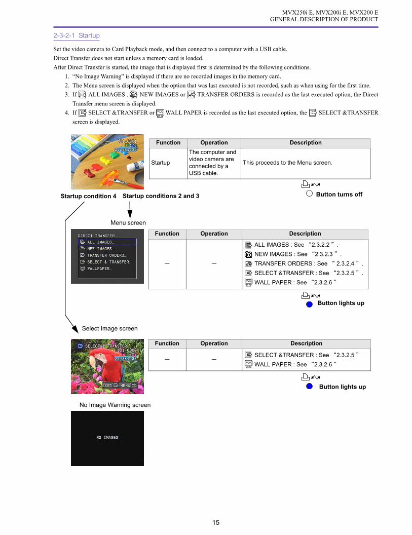
2-3-2-1 Startup
Set the video camera to Card Playback mode, and then connect to a computer with a USB cable.
Direct Transfer does not start unless a memory card is loaded.
After Direct Transfer is started, the image that is displayed first is determined by the following conditions.
1. “No Image Warning” is displayed if there are no recorded images in the memory card.
2. The Menu screen is displayed when the option that was last executed is not recorded, such as when using for the first time.
3. If ALL IMAGES , NEW IMAGES or TRANSFER ORDERS is recorded as the last executed option, the Direct
Transfer menu screen is displayed.
4. If SELECT &TRANSFER or WALL PAPER is recorded as the last executed option, the SELECT &TRANSFER
screen is displayed.
Function Operation Description
Function Operation Description
Startup
The computer and video camera are connected by a USB cable.
This proceeds to the Menu screen.
ALL IMAGES : See 2.3.2.2 .
NEW IMAGES : See 2.3.2.3 .
TRANSFER ORDERS : See 2.3.2.4 .
SELECT &TRANSFER : See 2.3.2.5 .
WALL PAPER : See 2.3.2.6
SELECT &TRANSFER : See 2.3.2.5
WALL PAPER : See 2.3.2.6
Menu screen
Select Image screen
Function Operation Description
Startup conditions 2 and 3
No Image Warning screen
Button lights up
Button turns offStartup condition 4
Button lights up
MVX250i E, MVX200i E, MVX200 EGENERAL DESCRIPTION OF PRODUCT
16
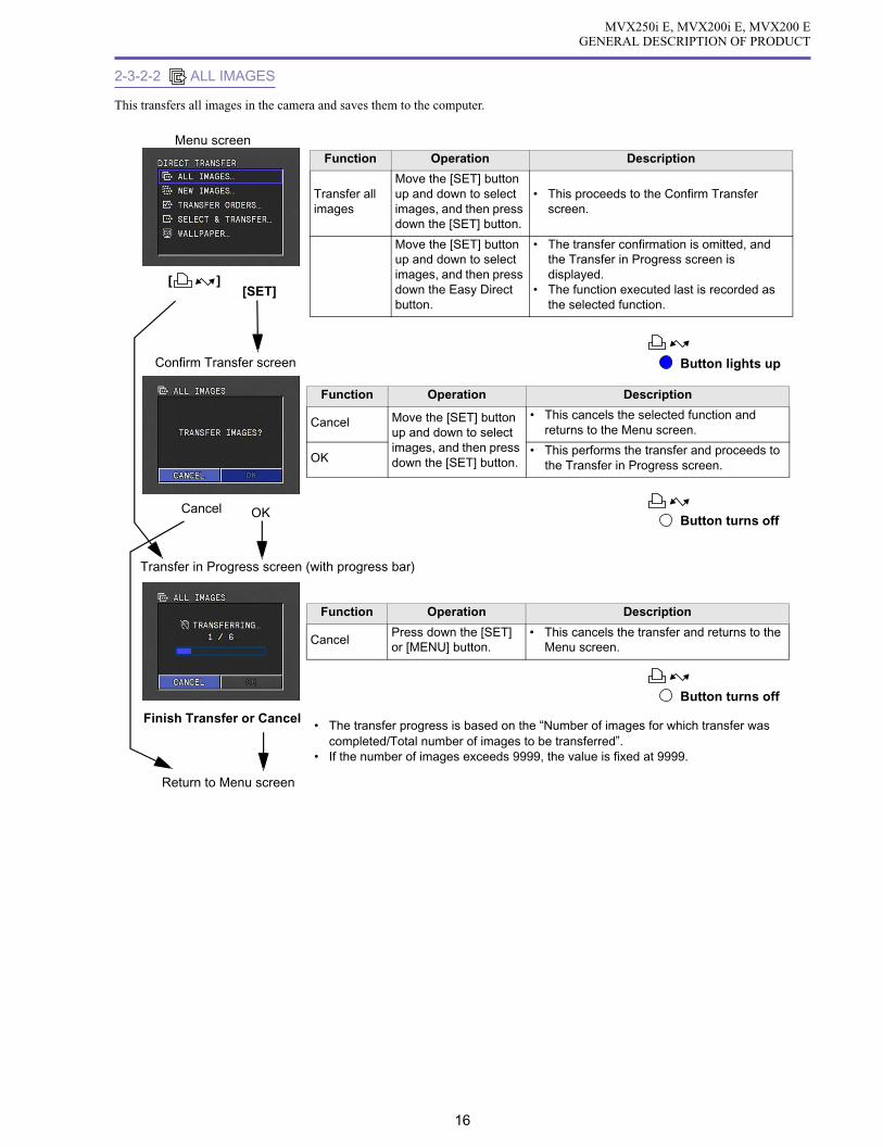
2-3-2-2 ALL IMAGES
This transfers all images in the camera and saves them to the computer.
Function Operation Description
CancelPress down the [SET] or [MENU] button.
• This cancels the transfer and returns to the Menu screen.
Button turns off
Function Operation Description
Transfer all images
Move the [SET] button up and down to select images, and then press down the [SET] button.
• This proceeds to the Confirm Transfer screen.
Move the [SET] button up and down to select images, and then press down the Easy Direct button.
• The transfer confirmation is omitted, and the Transfer in Progress screen is displayed.
• The function executed last is recorded as the selected function.
Menu screen
Confirm Transfer screen
Function Operation Description
Cancel Move the [SET] button up and down to select images, and then press down the [SET] button.
• This cancels the selected function and returns to the Menu screen.
OK• This performs the transfer and proceeds to
the Transfer in Progress screen.
Transfer in Progress screen (with progress bar)
• The transfer progress is based on the “Number of images for which transfer was completed/Total number of images to be transferred”.
• If the number of images exceeds 9999, the value is fixed at 9999.
Return to Menu screen
Button lights up
Button turns offCancel OK
Finish Transfer or Cancel
[SET][ ]

MVX250i E, MVX200i E, MVX200 EGENERAL DESCRIPTION OF PRODUCT
17
2-3-2-3 NEW IMAGES
All untransferred images are transferred and saved to the computer.
Function Operation Description
Transfer untransferred images
Move the [SET] button up and down to select images, and then press down the [SET] button.
• This proceeds to the Confirm Transfer screen.
Move the [SET] button up and down to select images, and then press down the Easy Direct button.
• The transfer confirmation is omitted, and the Transfer in Progress screen is displayed.
• The function executed last is recorded as the selected function.
Menu screen
Confirm Transfer screen
Function Operation Description
Cancel Move the [SET] button up and down to select images, and then press down the [SET] button.
• This cancels the selected function and returns to the Menu screen.
OK• This performs the transfer and proceeds to
the Transfer in Progress screen.
[SET]
Function Operation Description
CancelPress down the [SET] or [MENU] button.
• This cancels the transfer and returns to the Menu screen.
Transfer in Progress screen (with progress bar)
• The transfer progress is based on the “Number of images for which transfer was completed/Total number of images to be transferred”.
• If the number of images exceeds 9999, the value is fixed at 9999.
Return to Menu screen
OKCancel
Finish Transfer or Cancel
Button lights up
Button lights up
Button lights up
[ ]

MVX250i E, MVX200i E, MVX200 EGENERAL DESCRIPTION OF PRODUCT
18
2-3-2-4 TRANSFER ORDERS
All images designated for sending are transferred and saved to the computer.
Function Operation Description
CancelPress down the [SET] or [MENU] button.
• This cancels the transfer and returns to the Menu screen.
Function Operation Description
Transfer send-designated images
Move the [SET] button up and down to select images, and then press down the [SET] button.
• This proceeds to the Confirm Transfer screen.
Move the [SET] button up and down to select images, and then press down the Easy Direct button.
• The transfer confirmation is omitted, and the Transfer in Progress screen is displayed.
• The function executed last is recorded as the selected function.
Menu screen
Confirm Transfer screenFunction Operation Description
Cancel Move the [SET] button up and down to select images, and then press down the [SET] button.
• This cancels the selected function and returns to the Menu screen.
OK• This performs the transfer and proceeds to
the Transfer in Progress screen.
[SET]
Function Operation Description
• After analysis of the send-designated images is complete, this proceeds to the Transfer in Progress screen (with progress bar).
Transfer in Progress screen (with progress bar)
• The transfer progress is based on the “Number of images for which transfer was completed/Total number of images to be transferred”.
• If the number of images exceeds 9999, the value is fixed at 9999.Return to Menu screen
Button lights up
Button turns off
Button turns off
Button turns off
Analyzing Send-designated Images screen
OK
Analysis Complete
Cancel
Finish Transfer or Cancel
[ ]

MVX250i E, MVX200i E, MVX200 EGENERAL DESCRIPTION OF PRODUCT
19
2-3-2-5 SELECT & TRANSFER
The user views the images one at a time and transfers and saves them to the computer.
Function Operation Description
Select images for transfer
Move the [SET] button up and down to select images, and then press down the [SET] button.
• This proceeds to the Confirm Transfer screen.
Move the [SET] button up and down to select images, and then press down the Easy Direct button.
• The transfer confirmation is omitted, and the Transfer in Progress screen is displayed.
• The function executed last is recorded as the selected function.
Menu screen
Select Image screenFunction Operation Description
Transfer images
Press [SET] orbutton.
• This transfers the selected images.• After inputting the transfer, the user can
immediately continue to select other images and input transfer even while the transfer of an image is in progress.
• If a file that cannot be played is selected for transfer, a warning screen is displayed.
Menu display Press [ MENU] button.
• If an image is being transferred, this proceeds to the Transfer in Progress screen.
• This returns to the Menu screen if an image is being transferred.
Change image
Press [CARD +/–] buttons.
• This moves the image selection forward/backward.
• Changes can be made even if image transfer is in progress.
Function Operation Description
• When the transfer is completed, this returns to the Menu screen.
Warning screen
Return to Menu screen
[MENU] button while image transfer is in progress
or [SET]
[MENU] button while image transfer is not in progress
Button lights up
Button lights up
Button flashing
Transfer complete
Function Operation Description
• The warning screen is displayed for about one second, and then it returns to the Select Image screen.
Button lights up
Image Transfer in Progress screen (no progress bar)
Button flashing(Image transfer in progress)
[ ]

MVX250i E, MVX200i E, MVX200 EGENERAL DESCRIPTION OF PRODUCT
20
2-3-2-6 WALL PAPER
The user views the images one at a time and transfers and saves them to the computer.
The transferred image is displayed on the computer desktop
Function Operation Description
Set image as computer wallpaper
Move the [SET] button up and down to select images, and then press down the [SET] button.
• This proceeds to the Confirm Transfer screen.
Move the [SET] button up and down to select images, and then press down the Easy Direct button.
• The transfer confirmation is omitted, and the Transfer in Progress screen is displayed.
• The function executed last is recorded as the selected function.
Menu screen
Select Image screenFunction Operation Description
Transfer images
Press [SET] or button
• This transfers the selected images.• After inputting the transfer, the user can
immediately continue to select other images and input transfer even while the transfer of an image is in progress.
• A warning screen is displayed if the transfer is made with a motion video file selected.
Menu display Press [MENU] button
• If an image is being transferred, this proceeds to the Transfer in Progress screen.
• This returns to the Menu screen if an image is being transferred.
Change image
Press [CARD +/–] buttons
• This moves the image selection forward/backward.
• Changes can be made even if image transfer is in progress.
or [SET] button
Function Operation Description
• When the transfer is completed, this returns to the Menu screen.
Image Transfer in Progress screen (no progress bar)
Return to Menu screen
Warning screen
Function Operation Description
• The warning screen is displayed for about one second, and then it returns to the Select Image screen.
Button lights up Button flashing(Image transfer in progress)
Button flashing
Button lights up
[MENU] button while image transfer is in progress
[MENU] button while image transfer is not in progress
Button lights up
[ ]

MVX250i E, MVX200i E, MVX200 EGENERAL DESCRIPTION OF PRODUCT
21
3. Performance
MVX250i E, MVX200i E, MVX200 E
1 Type VCR- integrated camera
2 Recording system Rotating two-head helical scan azimuth recording
Consumer electronics digital DVC (SD specs)
Complies with NTSC system (625 lines, 50 fields)
2-1 Video signal recording system Digital component recording.
R-Y, B-Y = 6.75MHz
2-1-1 Quantized bits 8bits
2-2 Audio signal recording system PCM digital recording.
16-bit : 48KHz 2 ch (Stereo 1)
12-bit : 32KHz 4 ch (Stereo 1 and 2)
2-3 Tracking 2-frequency pilot system
2-4 Tape speed Approx. 18.83mm / sec (in SP mode)
Approx. 12.57mm / sec (in LP mode)
2-5 Head drum
2-5-1 Drum diameter 21.7mm
2-5-2 Rpms 9000 / 1.001 rotations / minute
2-5-3 Heads Video heads : 2
3 Recording / playback time 80 minutes maximum (in SP mode), using 80-minute tape
120 minutes maximum (in LP mode), using 80-minute tape
3-1 Continuous recording time / actual recording time / playback time using battery
4 Compatible cassette tape Mini DVC specs
4-1 Tape type Vapor - deposited metal tape
4-2 Tape width 6.35mm
4-3 Tape thickness 7µm or 5.3µm
5 Camera
5-1 Image sensing device 1 / 4.5 - inch interlaced CCD
5-1-1 Total number of pixels Approx. 1.33 megapixels (1363H × 975V)
5-1-2 Effective pixels
In tape recording Approx. 860,000 pixels (1072H × 804V)
In card recording Approx. 1,230,000 pixels (1280H × 960V)
High- resolution 16: 9 shooting Approx. 920,000 pixels (1280(H) × 720(V) when image stabilizer is OFF)
(in tape mode) Approx. 790,000 pixels (1184(H) × 666(V) when image stabilizer is ON)
5-1-3 Filter Color correction filter
5-1-4 Color separation system Differential readout
5-1-5 Signal configuration NTSC standard color TV signal
5-1-6 Scanning system 625 lines, 50 fields / 25 frames
5-1-7 Minimum subject illumination
In Auto mode Approx. 6.0 lx (1/25 sec. shutter speed)
In Low light mode Approx. 3.0 lx (1/12.5 sec. shutter speed)
In Night mode Approx. 1.5 lx (1/6 sec. shutter speed)
5-1-8 Subject illumination range Approx. 1.5 lx to approx. 100,000 lx
MVX250i E, MVX200i E, MVX200 E
When viewfinder is used When LCD monitor is used
Continuous Actual Continuous Actual Continuousrecording recording recording recording playback
NB-2L Approx. 95 min Approx.50 min Approx. 75 min Approx. 40 min Approx. 85 min
NB-2LH Approx.115 min Approx. 65 min Approx. 90 min Approx. 50 min Approx.105 min
BP-2L12 Approx.200 min Approx.110 min Approx.150 min Approx. 85 min Approx.175 min
BP-2L14 Approx.240 min Approx.135 min Approx.190 min Approx.105 min Approx.220 min

MVX250i E, MVX200i E, MVX200 EGENERAL DESCRIPTION OF PRODUCT
22
5-2 Photo lens
5-2-1 Nominal focal length
Tape recording MVX250i E 3.5 to 63 mm 18× zoom (35 mm film equivalent : 45.4 to 817.2 mm)
MVX200i E, MVX200 E
3.5 to 49 mm 14× zoom (35 mm film equivalent : 45.4 to 635.6 mm)
Card recording MVX250i E 3.5 to 63 mm 18× zoom (35 mm film equivalent : 37.9 to 682.2 mm)
MVX200i E, MVX200 E
3.5 to 49 mm 14× zoom (35 mm film equivalent : 37.9 to 530.6 mm)
5-2-2 Nominal diametric ratio
MVX250i E 1 : 1.8 (F3.4 on tele end)
1 : 1.8 (F3.3 on tele end)
MVX200i E, MVX200 E
1 : 1.8 (F3.1 on tele end)
5-2-3 Lens configuration 10 elements in 8 groups, using one two- sided aspherical lens
5-2-4 Focus adjustment Inner focus type, manually adjustable (adjusted by rotating multi- dial)
5-2-5 Minimum object distance 10 mm (AF linked ; wide end), 1 m for full zoom area (from lens tip)
5-2-6 Power zoom Multi- level adjustable power zoom. Slide lever operation. Zoom speed can be adjusted by mov-
ing slide lever.
Manual zoom not possible (No zoom ring)
5-2-6-1 Zoom speed
Optical zoom Approx. 4.3 seconds to approx. 50 seconds
Using electronic zoom Approx. 5.8 seconds to approx. 55 seconds
5-2-7 Focal length display None. Simple zoom display inside finder.
5-2-8 Macro mechanism Wide end macro
5-2-9 Macro shooting distance 10 mm (from lens front)
5-2-10 Filter diameter 34 mm P0.5
5-2-11 Accessory lens, filter Can use WD-H34, TL-H34, FS-34U
5-2-12 Lens hood None
5-2-13 Lens cap Included ; Screw-on type
5-3 Digital zoom
5-3-1 During tape recording
MVX250i E To 72× (approx. 252 mm (35 mm equivalent : 3,269 mm)), to 360× (approx. 1,260 mm (35 mm
equivalent : 16,344 mm))
MVX200i E, MVX200 E
To 56× (approx. 196 mm (35 mm equivalent: 2,542 mm)), to 280× (approx. 980 mm (35 mm
equivalent : 12,712 mm))
5-3-2 During card recording
MVX250i E To 72× (approx. 252 mm (35 mm equivalent : 2,728.8 mm))
MVX200i E, MVX200 E
To 56× (approx. 196 mm (35 mm equivalent : 2,122.4 mm))
5-4 Image stabilization function Supported
5-4-1 System Electronic image stabilizer
5-4-2 Image stabilization detection Angular velocity sensing (using piezoelectric vibration sensor)
5-5 Shooting modes Motion video shooting mode, photo shooting mode (card recording)
5-5-1 Tape mode Normal motion video is recorded (interlaced scanning) on miniDV cassettes.
In addition, when an SD memory card (or MultiMediaCard) is installed and [ ] Fine], or [
] Normal] is selected for [Photo record] on the menu, still images (640 × 480) are recorded
on the memory card while motion video is recorded on the tape. (Simultaneous recording)
5-5-2 Card mode Still images (progressive photo images: JPEG) or motion video (Motion- JPEG 15 (12.5) frames/
sec audio (monaural)) can be recorded on SD memory card (or MultiMediaCard).
Refer to the memory card system on page 27.
5-6 Exposure control
5-6-1 Program AE Full Auto mode, Auto mode, Sports mode, Portrait mode, Spotlight mode, Surf (Sand) & Snow
mode, Low Light mode, Night mode, Night+ mode, Super Night mode (Night+, Super Night
mode are for MVX250i E only)

MVX250i E, MVX200i E, MVX200 EGENERAL DESCRIPTION OF PRODUCT
23
5-6-2 AE photometric system
Tape recording Center- bottom- weighted average :
Full Auto mode, Auto mode, Sports mode, Portrait mode, Low Light mode,
Night mode, Night+ mode, Super Night mode (Night+ mode and Super
Night mode are for MVX250i E only)
All area average photometry + 128-segment (16H × 8V) evaluative photometry :
Spotlight mode, Surf & Snow mode
Card recording Evaluative photometry (128- segment):
Full Auto mode, Auto mode, Sports mode, Portrait mode, Low Light mode,
Night mode, Night+ mode and Super Night mode (Night+ mode and Su-
per Night mode are available in MVX250i E only.)
All area average photometry + 128- segment evaluative photometry :
Spotlight mode, Surf (Sand) &Snow mode
5-6-3 Exposure correction function
AE lock AE is locked by pressing the EXP lock button. After the AE is locked, the exposure level can be
corrected using the SET button (except in Full Auto mode).
Exposure correction amount ± 11 levels(–11 to 0 to +11).
Indicated as number in the viewfinder (EXP lock ± 0).
5-6-4 Electronic shutter
5-6-4-1 In Auto mode <Tape mode>
Auto : 1/25 to 1/500 sec (with auto slow shutter ON)
1/50 to 1/500 sec (with auto slow shutter OFF)
Select : 1/50, 1/120, 1/250, 1/500, 1/1000 or 1/2000 sec.
<Card mode>
Auto : 1/12.5 to 1/250 sec (with auto slow shutter ON)
1/25 to 1/250 sec (with auto slow shutter OFF)
Select : 1/50, 1/120 or 1/250 sec.
5-6-4-2 In Low Light mode 1/12.5 (fixed speed)
5-6-4-3 In Night mode
Tape recording 1/6 sec to 1/500 sec (same for Night+, Super Night modes of MVX250i E)
Card recording 1/2 sec to 1/250 sec (same for Night+, Super Night modes of MVX250i E)
5-7 AF (Auto Focus)
5-7-1 System TTL–video signal sensing
5-7-2 AF range finding area
During Tape mode Screen center
During Card mode One of 3 locations on screen selected (screen center only in full auto mode)
5-7-3 AF Range finding frame display
During Tape mode None
During Card mode Supported (During focus priority : User can select desired frame (green) from one of the 3- point
range finding frame display. Screen center only during Full Auto mode.)
5-7-4 AF operating range 10 mm to infinite (at wide end) ; 1 mm to infinite in full zoom area from lens front
5-7-5 AF operation illumination range Approx. 50 lx - 100,000 lx
5-7-6 AF mode switching Continuous AF / manual focus / infinite focus. AF ON/OFF switching is possible in all but Full
Auto mode (operation by pressing focus button).
Manual focus During manual focus (AF OFF), the MF indicator appears in the viewfinder.
Infinity focus The shooting distance can be forced to infinity by holding down the focus button in the auto
focus mode.
5-8 Viewfinder 0.33-inch Color LCD (approx. 113,000 pixels). ON when LCD monitor closed (panel facing in-
wards) and during mirror shooting
5-8-1 Rotation Possible (70 deg. upward to support low-angle shooting)
5-8-2 Detaching eyepiece Possible
5-8-3 Diopter movement range +1.0 to –5.0 diopter (when eye is at eyepiece)
5-8-4 Lens configuration Two elements in two groups
5-9 LCD monitor 2.5-inch Color LCD Approx. 123,000 pixels (560 (H) × 220 (V)) TFT active matrix drive RGB
delta arrangement; ON when LCD monitor not closed (panel facing inwards)
5-9-1 Angle adjustment Possible ; Monitoring is possible for high-angle, low-angle, and mirror shooting

MVX250i E, MVX200i E, MVX200 EGENERAL DESCRIPTION OF PRODUCT
24
5-9-2 Information display Color display of operating mode, simple zoom position, remaining battery charge, remaining
tape, time code, warnings and other indications. The indicators are not displayed during mirror
shooting. 8 languages of Japanese, Chinese (simplified Chinese), English, German, French,
Italian, Spanish and Russian supported.
Relationship between LCD monitor and viewfinder
*1 : Mirror mode possible by menu selection.
*2 : During mirror mode, only or and the self-timer display
appear.
5-10 White balance adjustment TTL 128-segments, new white extraction system FAWB. Includes set / preset (outdoor: 5,600 k;
indoor: 3,200 k)
(selected from camera menu).
5-10-1 Adjustment range 2,800 k to 8,000 k
5-11 Digital feature functions The following modes are provided : Fader, Effects, Multi-screen
Fader : Linked to Start/Stop button. Can be used 1 time when Fade mode displayed.
(Mode indication goes out when Fader ends.)
Effects : Effect continues until mode is turned OFF.
Multi-screen : Loads and displays multiple screens at set interval or manually. Displayed until
mode is turned OFF.
Card mix : Mixes and displays included sample images, images recorded on cards and mo-
tion video.
5-11-1 Fader Audio synchronized fader
(Only in recording on tape) Auto Fade (Japanese model : Fade to white, Overseas model: Fade to black), Wipe, Corner Wipe,
Jump, Flip, Puzzle, Zigzag, Beam, Tide
5-11-1-1 Fade time Approx. 4 sec
5-11-2 Effects Art, Black and White, Sepia, Mosaic, Ball, Cube, Wave, Color Mask, Mirror (Only Black and
White is available during card recording)
Effect function turned ON / OFF from D. Effect button. Toggle operation
5-11-3 Multi-screen (tape recording only ; excludes Night mode)
5-11-3-1 Number of screens 4 (2 × 2), 9 (3 × 3), 16 (4 × 4)
5-11-3-2 Operation mode Manual, Fast (4 frames), Normal (6 frames), Slow (8 frames)
During Low Light mode, the settings are Fast (4 frames), Normal (8 frames), and Slow (12
frames)
5-12 Card Mix
5-12-1 Mix type Card Chroma Key, Card Lumi. Key, Camera Chroma Key, Card Animation
5-12-2 Mix level adjustment Possible. 32 levels
5-12-3 Animation type 3 types : Corner Animation, Straight Animation or Random Animation (Animation Titles are
already recorded in the supplied SD Memory Card SDC-8M.)
5-12-4 Availability in operation mode
Camera mode, Card / Camera mode VCR mode and Card Playback
LCD panel position LCD panel CVF LCD panel CVF
Panel closed (panel facing inwards) OFF ON OFF ON
Panel closed (panel facing outwards) ON OFF ON OFF
Panel open ON OFF ON OFF
Mirror shooting*2 ON*1 ON ON OFF
Camera
Card (Still Image) Card (Motion Video) Tape (Still Image) Tape (Motion Video)
Fader × × ×
Effect Black and White only Black and White only
Multi-screen × ×
Card Mix × ×

MVX250i E, MVX200i E, MVX200 EGENERAL DESCRIPTION OF PRODUCT
25
5-13 Built-in microphone Stereo using electret condenser microphone
5-13-1 Wind screen function Supported ; AUTO or OFF can be selected (Selected from menu. However, built-in microphone
only.)
5-14 Auxiliary light (MVX250i E, MVX250i E only)
Equipped with white LED
5-14-1 Lighting mode Night+ mode : LED is forcibly lighted.
Super Night mode : LED lights depending on brightness of the subject.
5-15 Other additional functions
5-15-1 Time code Displays recording time (0:00:00 to 7:59:59) and records in sub-code area.
5-15-2 Data code The date and camera information during recording are automatically recorded and can be dis-
played during playback.
a. Time and date Automatic calendar range: January 1, 2004 through December 31, 2030 (the initial setting is
January 1, 2004)
One of the following three formats can be selected for the date / time display.
World clock capability (select the name of your destination city and the date and time are auto-
matically adjusted to the local date and time.) Supports daylight savings time.
During playback, time can be displayed in three different modes (date only, time and date, or
time only). (Time and date can be displayed for January 1, 1990 through December 31, 2089.)
b. Camera data Shutter speed and aperture value information are recorded (but not displayed during recording),
and can be displayed during playback.
5-15-3 Accessory shoe Supported. Advanced accessory shoe supported (MVX250i E only)
5-15-4 REC Search mechanism Supported. Tape can be played (forward or reverse) by pressing the REC Search button while
camera recording is paused. (When REC Search ends, camera recording is paused again.)
5-15-5 REC Review Supported. Accessed by operating the Recording Check button when camera recording is paused
(in Tape mode only).
5-15-6 Zero Set Memory Supported. This function allows you to rewind or fast-forward the tape to the position where the
WL-D83 Zero Set Memory key is pressed (the counter value is set to 0:00:00). (During record-
ing, only zero setting is allowed. This function can be used in Playback mode.) “ M ” display
appears at the far right of the counter.
5-15-7 Remote control reception ON/OFF Possible. This can be done in Camera mode and VCR mode (by selecting from menu).
5-15-8 Headphone volume adjustment Possible. Adjustable with SET button
5-15-9 16:9 shooting High- resolution 16: 9 (CCD extraction equivalent to approx. 790,000 pixels when image stabi-
lizer is ON or CCD extraction equivalent to approx. 920,000 pixels when image stabilizer is
OFF). If 16: 9 mode is selected, the screen switches to a letterbox display (with black bands
(masked) at the top and bottom)). In Tape mode only
5-15-10 AEB shooting Included. (First shot : No correction, Second shot : -0.5 level, Third shot : +0.5 level)
5-15-11 Skin detail mode When skin areas are detected, they are expressed softly, and the small blemishes, lines, etc.
become unnoticeable. ON or OFF setting possible.
5-15-12 Still image check time setting The time used for checking still images can be set after the photo button is pressed and its
operation is released. One of 6 settings; OFF (0 sec), 2, 4, 6, 8 or 10 seconds can be selected as
the setting mode.
6 Recorder
6-1 Recording functions Camera shooting and recording, DV input recording**, analog input recording
** : MVX250i E, MVX200i E only
6-1-1 Recording format Consumer electronics digital DVC (SD specs)
6-1-2 Tape speed Approx. 18.83 mm / second (in SP mode), approx. 12.57 mm / second (in LP mode)
6-1-3 DV input recording Complies with IEEE1394.
Records video / audio signals from a digital video camera connected through a DV cable.
6-1-4 Analog input recording Records analog video / audio signals using an S-Video terminal or AV terminal.
(MVX250i E, MVX200i E only)
6-1-5 Priority of terminals during recording DV terminal > S-Video terminal > AV terminal (MVX250i E, MVX200i E only)
6-2 Audio Dubbing Recording Possible. (SD spec tapes only)
6-2-1 Insert-capable tape Only tapes with 12- bit/ SP recording (other than 4- channel simultaneous recording) can be used
in Audio Dubbing Recording.

MVX250i E, MVX200i E, MVX200 EGENERAL DESCRIPTION OF PRODUCT
26
6-2-2 Audio Dubbing signal input Audio signal from LINE (AV terminal) or microphone (external > internal). MVX200i E has no
external microphone terminal. MVX200 E has no external microphone terminal and line in
function.
6-2-3 Switching to Audio Dubbing Press audio dubbing button on remote control while playback is paused.
6-3 Playback functions Standard Playback and Superb Playback
6-3-1 Standard Playback
a. Video Video recorded in SP and LP modes
b. Audio 16-bit Supports the following sampling frequencies : 48 kHz, 44.1 kHz, 32 kHz.
12-bit Sampling frequency : 32 kHz
Stereo 1, Stereo 2, or mixed playback of Stereo 1 and Stereo 2 (variable mix ratio)
6-3-2 Special Playback Plays video only
a. Still image playback Pure frame playback
b. Fast-forward playback Approx. 11.5× speed.
c. Rewind playback Approx. 11.5× speed.
d. Frame playback Forward/reverse frame feeding
e. Slow playback Forward/reverse 1/3× speed
f. 1× SP playback Forward/reverse 1× speed
g. 2× SP playback Forward/reverse 2× speed
6-4 Tape fast-forward / rewind time Approx. 2 minutes and 20 seconds (using 60-minute tape)
6-5 Search
6-5-1 Date search If there is more than one recording date, this function cue up to the position where the date
changes. Forward/reverse date search (use the / keys on the remote control after select-
ing Date search with the remote control Search Select key)
Search can be set for up to 10 images before or after the current position.
6-5-4 Index search None
6-5-5 End search When a tape is played back upon completion of the shooting, this function transports the tape to
the position where the shooting last ended, it cues to the end of the shooting on the tape, and then
places the tape in the stop mode. Furthermore, when an end search is being performed, the tape
is played back starting about 4 seconds before the end of the shooting, enabling the image imme-
diately before the end to be checked. However, this function does not work when the tape has
been removed after shooting.
6-6 Input signals
6-6-1 DV terminal SD format signals complying with IEEE1394– AV / C protocol (MVX250i E, MVX200i E only)
6-6-2 AV terminal (MVX250i E, MVX200i E only)
a. Video signals
Types of signals PAL standard color video signals
Impedance 75 ΩSignal level 1Vp-p (composite)
b. Audio signals
Types of signals Stereo audio signals
Impedance Min. 40 kΩSignal level −10dBv
6-6-3 S Video terminal (MVX250i E, MVX200i E only)
Signal configuration PAL Y/C separated video signal
Impedance 75 ΩSignal level 0.3Vp-p (color burst signal)
6-6-4 Microphone terminal Included. (MVX250i E only)
6-6-5 USB terminal Supports USB 2.0 FullSpeed class.
6-7 Output signals (MVX250i E only)
6-7-1 DV terminal SD format signals complying with IEEE1394-AV/C protocol
6-7-2 AV terminal
a. Video signals
Types of signals PAL standard color video signals
Impedance 75 ΩSignal level 1 Vp-p (composite)
Horizontal resolution
Self-recording/playback Approx. 530 TV lines (screen center)
Camera EE OUT Max. approx. 530 TV lines (screen center)

MVX250i E, MVX200i E, MVX200 EGENERAL DESCRIPTION OF PRODUCT
27
b. Audio signals
Types of signals Stereo audio signal
Impedance Max. 3 kΩSignal level −10 dBv
Frequency characteristic 60 Hz to 16 kHz (Range between 1 kHz standard ±3 dB)
Audio signal S/N
Built-in microphone input Min. 48 dB
External microphone input Min. 48 dB (However, the MVX200i E, MVX200 E model does not have an external micro-
phone input terminal.)
6-7-3 S-Video terminal
Signal configuration PAL Y/C separated video signal
Video signals 1 Vp-p (brightness + synchronization signal)
Color signal 0.3 Vp-p (Color burst signal)
Impedance 75 ΩSignal level 0.3 Vp-p (Color burst signal)
Brightness signal S/N Min. 45 dB
Horizontal resolution
Self recording / playback Conforms to camera EE OUT
Camera EE OUT Max. approx. 530 TV lines (screen center)
6-7-4 Headphone terminal φ 3.5 mm stereo mini jack
Output impedance 100 ΩSignal level −25 dBv (with 16 Ω load at maximum volume)
6-7-5 USB terminal Supports USB2.0 FullSpeed class
USB device class Independent class, PTP class, mass storage class, audio class, video class
Compatible computer systems Windows : IBM PC/AT compatible, NEC PC98-NX Series
Macintosh : Power Macintosh, PowerBook, iMac, iBook
PC operating system Windows : Windows 98, Windows 98SE, Windows ME, Windows 2000, Windows XP
Macintosh : Mac OS 9 or later
6-8 Memory card system
6-8-1 Types of memory cards used SD memory card, Multimedia card
6-8-2 Recordable image types
a. Still image JPEG recording
In Camera mode When [ ] Fine], or [ ] Normal] is selected for [PHOTO REC] on the [CAM SET UP]
menu, still images can be recorded on the memory card by operating the photo button while
motion video is being recorded on the tape. (Tape simultaneous recording function: VGA still
images)
In Card Recording mode Still image is recorded using the Photo button (image size and image quality are selectable).
Writing in Progress warning is displayed in the EVF/ LCD.
During playback mode Still image is recorded using the photo button during tape playback (pressed halfway down for
still image playback and pressed all the way down for recording). (VGA still images)
Also, DV input images (when no tape loaded or loaded tape is stopped) can be recorded by
pressing the photo button (pressing halfway captures still image of the DV input, pressing all the
way down records the image).
b. Motion video AVI (Video data: Motion JPEG / Audio data: WAVE (monoaural))
Records only camera images during Card Record mode and from tape during VCR mode (re-
cording from DV input,
AV input and S- Video input are disabled).
Image quality in recording onto card from tape / DV input
Source Source recording system Image recorded on card
Tape / DV input Progressive or frame motion video recording Progressive or frame image
Tape / DV input Normal motion video recording Simple pure frame image
Analog AV input Normal motion video recording Field image

MVX250i E, MVX200i E, MVX200 EGENERAL DESCRIPTION OF PRODUCT
28
6-8-3 File names/folder names Based on the DCF (Design rule for Camera File systems) and still image (Exif 2.2) file manage-
ment specifications / DPOF (Digital Print Order Format) file management specifications, the
following names are assigned to recorded cards after formatting in the Format menu.
a. Card volume label CANON DV
xxx : Folder No., yyyy : File number, z : A to Z
(*1) Comes from motion video file of same File No.
DCF folder and file name //DCIM/xxxCANON/AUT_yyyy.JPG
xxx : folder No., yyyy : file No.
b. File number Files are managed internally by folder No. and file No.
Photographed images are assigned file numbers from 0001 to 9900, and are stored in folders
(100 files to a folder). Each folder is assigned numbers 100 to 998.
Relationship between folder No. and file No.
Photographed images start from 101-0101, and are basically numbered to be greater than Direc-
tory No.- File No. of files saved on MultiMediaCards.
6-8-4 Recorded image size/image quality
a. Still image recording
In tape simultaneous recording 640 × 480 dots(VGA) / Switchable between Fine and Normal
In card / camera mode 1280 × 960 dots (XGA), 640 × 480 dots (VGA) / Switchable between Super Fine, Fine, and
Normal
During tape playback, line input, and card recording of DV input image
640 × 480 dots (VGA) / Switchable between Super Fine, Fine, and Normal
b. Motion video recording (Motion JPEG)
320 × 240, 160 × 120 dots 12.5 frames / sec
Types of files Compression system Folder name and file name
Still image (Exif 2.2) file JPEG //DCIM/xxxCANON/IMG_yyyy.JPG
Motion video file Motion JPEG //DCIM/xxxCANON/MVIyyyy.AVI
Motion video thumbnail file (*1) JPEG //DCIM/xxxCANON/MVIyyyy.THM
Photo stitch JPEG //DCIM/xxxCANON/STz_yyyy.JPG
Zoom browser JPEG //DCIM/xxxCANON/AUT_yyyy.JPG
DPOF file TEXT //MISC/AUTPRINT.MRK
Work file TEXT //DCIM/CANONMSC/xxx.tmp
Folder No. File No. Saved files
100 0001 0002 0003 ···· 0099 0100 Sample image included at time of shipping
101 0101 0102 0103 ···· 0199 0200
102 0201 0202 0203 ···· 0299 0300
···
198 9801 9802 9803 ···· 9899 9900 Photographed image recording area
200 0001 0002 0003 ···· 0099 0100
···
998 9801 9802 9803 ···· 9899 9900

MVX250i E, MVX200i E, MVX200 EGENERAL DESCRIPTION OF PRODUCT
29
6-8-5 Number of recorded images / recording time
When a MultiMediaCard is used, the maximum recording time per shot is about 10 sec
(for 320 × 240) or about 30 sec (for 160 × 120).
* The included SDC-8M contains prerecorded title images, therefore the actual number of recorded images will be
less than above.
* The given number of recorded images is only for reference. The number will vary greatly depending on the focal
length, subject and other conditions when taking pictures.
* Windows XP : To connect the ELURA70 / 65 / 60A to a computer, the maximum continuous recording time of
movies on a memory card should be no longer than Approx. 12 minutes in 320 × 240 and 35 minutes in 160 × 120.
SDC-8M SDC-128M
a. Still image recording 1280 × 960dots (SXGA) 640 × 480dots (VGA) 1280 × 960dots (SXGA) 640 × 480dots (VGA)
Super Fine Approx. 6 images Approx. 34 images Approx. 144 images Approx. 709 images
(approx. 850 KB per image) (approx. 175 KB per image) (approx. 850 KB per image) (approx. 175 KB per image)
Fine Approx. 10 images Approx. 50 images Approx. 222 images Approx. 975 images
(approx. 550 KB per image) (approx. 120 KB per image) (approx. 550 KB per image) (approx. 120 KB per image)
Normal Approx. 18 images Approx. 84 images Approx. 409 images Approx. 1560 images
(approx. 300 KB per image) (approx. 65 KB per image) (approx. 300 KB per image) (approx. 65 KB per image)
b. Motion video recording 320 × 240dots 160 × 120 dots 320 × 240 dots 160 × 120 dots
Maximum recording time Approx. 20 sec Approx. 50 sec Approx. 8 minutes Approx. 17 minutes
Data size per second Approx. 250 KB / sec Approx. 120 KB / sec Approx. 250 KB / sec Approx. 120 KB / sec
SDC-512M
a. Still image recording 1280 × 960dots (SXGA) 640 × 480dots (VGA)
Super Fine Approx. 577 images Approx. 2837 images
(approx. 850 KB per image) (approx. 175 KB per image)
Fine Approx. 891 images Approx. 3902 images
(approx. 550KB per image) (approx. 120KB per image)
Normal Approx. 1641 images Approx. 6243 images
(approx. 300 KB per image) (approx. 65 KB per image)
b. Motion video recording 320 × 240dots 160 × 120 dots
Maximum recording time Approx. 33 minutes Approx. 69 minutes
Data size per second Approx. 250 KB / sec Approx. 120 KB / sec

MVX250i E, MVX200i E, MVX200 EGENERAL DESCRIPTION OF PRODUCT
30
6-8-6 Continuous shooting Number of recorded images in continuous shooting
Fast frame feeding (5 frames / sec; 2 frames / sec when using flash)
Size Image quality VFL-1 Continuous images Remarks
Super Fine When not installed Up to 10 images
Fine (When flash is not Up to 10 images
1280 × 960Normal used) Up to 10 images
Super Fine Up to 10 images Maximum flash
Fine When flash is used Up to 10 images emission is 1/4
Normal Up to 10 images of single shot flash
Super Fine When not installed Up to 60 images
Fine (When flash is not Up to 60 images
640 × 480Normal used) Up to 60 images
Super Fine Up to 60 images Maximum flash
Fine When flash is used Up to 60 images emission is 1/4
Normal Up to 60 images of single shot flash
Normal frame feeding (3 frames / sec; 2 frames / sec when using flash)
Size Image quality VFL-1 Continuous images Remarks
Super Fine When not installed Up to 10 images
Fine (When flash is not Up to 10 images
1280 × 960Normal used) Up to 10 images
Super Fine Up to 10 images Maximum flash
Fine When flash is used Up to 10 images emission is 1/4
Normal Up to 10 images of single shot flash
Super Fine When not installed Up to 60 images
Fine (When flash is not Up to 60 images
640 × 480Normal used) Up to 60 images
Super Fine Up to 60 images Maximum flash
Fine When flash is used Up to 60 images emission is 1/4
Normal Up to 60 images of single shot flash

MVX250i E, MVX200i E, MVX200 EGENERAL DESCRIPTION OF PRODUCT
31
6-8-7 Card format Formats using format command in the main unit menu. Operation is not guaranteed with PC
formats as problems can occur with some OS.
6-8-8 Usable memory card
SD memory card San Disk : 8 MB, 16 MB, 32 MB, 64 MB, 128 MB, 256 MB
Matsushita Electric : 8 MB, 16 MB, 32 MB, 64 MB, 128 MB, 256 MB, 512 MB
Toshiba : 8 MB, 16 MB, 32 MB, 64 MB, 128 MB, 256 MB, 512 MB
MultiMediaCard San Disk : 8 MB, 16 MB, 32 MB, 64 MB
Hitachi : 16 MB, 32 MB, 64 MB
(However, this does not mean that the operation of all these memory cards is guaranteed.)
6-9 Digital feature playback function The following modes are provided : Fader, Effect, Multi-screen.
· Can be executed once when Fader mode is displayed in conjunction with pressing the button
(the mode display disappears when Fader ends).
· Effects : Effect continues until mode is turned OFF.
· Multi-screen : Loads and displays multiple screens at set interval or manually. Displayed until
mode is turned OFF.
6-9-1 Fader Audio synchronized Fader
Same as in recording mode. Auto Fade (Japanese model: Fade to white, Overseas model : Fade to
black), Wipe, Corner Wipe, Jump, Flip, Puzzle, Zigzag, Beam, Tide
Fade time Approx. 4 sec
6-9-2 Effects Same as in recording mode. Art, Black and White, Sepia, Mosaic, Ball, Cube, Wave, Color
Mask, Mirror (only in Tape mode)
Effect function turned ON / OFF from D. Effect button. Toggle operation
6-9-3 Multi-screen
a. Number of screens 4 (2 × 2), 9 (3 × 3), 16 (4 × 4)
b. Screen capture speed Manual, Fast (4 frames), Normal (6 frames), Slow (8 frames)
6-9-4 Card mix Not available
6-9-5 Availability in operation modes
6-10 Direct print Still images recorded on memory cards can be easily printed by connecting to (sold separately)
card photo printers CP-200/300, Camera Direct Printer compatible BJ printers PIXUS 470PD/
JP450i with supplied IFC-300PCU interface cable. DPOF print setup support (max. 200images)
6-10-1 Printable images Only the still images which have been recorded on the SD memory cards or MultiMediaCards.
6-10-2 Print format Single image/8-image print (layout of 8 pictures of same image : only when the card size paper
tray has been installed in the CP200/300). Printing not available from index screen.
6-10-3 Trimming Possible
6-10-4 Date printing Possible (when connected to PictBridge compatible printer except for the CP-200/CP-300.)
6-10-5 Number of print copies Easy Print : 1 to 99 sheets
DPOF printing : Max. 200 images, 1 to 99 each
Playback (VCR / Tape) Card playback
Fader ×
Effects ×
Multi-screen ×
Card Mix × ×

MVX250i E, MVX200i E, MVX200 EGENERAL DESCRIPTION OF PRODUCT
32
6-10-6 Print systems
Print manufacturer Canon Other
manufacturer
Printer specifications
CP specifications
CP specifications +
PictBridgespecifications
BJ Photospecifications only
BJ Photo specifications +
PictBridge specifications
PictBridge specifications only
Suitable printer CP-10/100 CP-200/300BJ-895PD/
535PD/F890PD,PIXUS 50i
PIXUS 990i, 900PD
Printer specifications when connected to MVX250i E, MVX200i E, MVX200 E(Controlled at printer side)
CP camera directcontrol
CP camera directspecifications
PictBridge control
PictBridge specifications
PictBridge specifications
PictBridge control
PictBridge specifications
PictBridge control
BJ camera direct control
BJ camera direc specifications
When the printer isconnected
DPOF printing screen
Prin
ting
func
tions
Paper size
Paper type
Paper setting
Borders/no borders
8-of-1 screen layout
Sectional printing
Image optimizing
Date printing
Trimming
): When the printer is supported
(When card size paper is used)
(Area selection)
(When card size paper is used)

MVX250i E, MVX200i E, MVX200 EGENERAL DESCRIPTION OF PRODUCT
33
6-11 Other
6-11-1 Consecutive shooting mechanism Can be used starting in Recording Pause or Stop mode, or starting with the power off. This does
not apply to cases where the cassette has been removed.
6-11-2 Automatic stop function When forward still image playback is continued for approx. 5 minutes, or reverse still image
playback is continued for approx. 5 minutes. When a condensation warning is displayed. When
the tape end or beginning is reached.
6-11-3 Power automatic stop function When Recording Pause continues for approx. 5 min. When the battery voltage falls below a
specified value.
6-11-4 Time code Automatically written during recording. Time code values range from 0:00:00:00 to 7:59:59:24
(hours:minutes:seconds:frames).
6-11-5 World clock display Set reference city (city of time clock setting) and select name of city when shooting. Date and
time are automatically adjusted to local date and time, and recorded in data code.
6-11-6 Speaker Built-in, volume control provided
6-11-7 File transfer
a. USB file transfer Still images (JPEG files) and motion video (Motion JPEG files) recorded on memory cards can
be uploaded to a PC and still images (JPEG files) on the PC can be downloaded to memory cards
in the camcorder by connecting the included IFC-300PCU interface cable between a USB port
on the PC and the USB port of the camcorder.
b. DV file transfer Still images (JPEG files) and motion video (Motion JPEG files) recorded on memory cards can
be uploaded to a PC and still images (JPEG files) and motion video (Motion JPEG files) on the
PC can be downloaded to memory cards in the camcorder by connecting a CV-150F (or CV-
250F) DV cable between an IEEE1394 port on the PC and the DV terminal of the camcorder.
6-11-8 Analog / Digital conversion Converts analog AV signals input to the AV terminal into digital DV signals in real-time and
(PAL models excluded) outputs the digital DV signals from the DV terminal.
When an 8 mm video player or VHS video player is connected with the camcorder using an AV
cable, and the camcorder is connected to a PC using a DV cable, playback images can be trans-
ferred from the 8 mm tape or VHS tape to the PC. (Under the VCR settings on the VCR menu
screen, set AV input ⇒ DV output to ON.)
6-11-9 Playback zoom If the zoom lever is flipped to the tele side during image playback from the tape or card (MVX250i
E only, except for motion video), the image being played back can be enlarged to 5 times its size.
When the zoom lever is flipped to the wide side, the enlarged image is returned to its original
size.
Position of the enlarged section during enlarged screen view can be changed by SET button. (On
the LCD monitor, a frame is displayed to show the zoom-in area, and the direction in which the
area can be moved by the SET button is indicated by / .) Toggling between the up/down
and left/right movement direction settings is performed by pressing the SET button. (“Left /
right” is the default setting when the mode is transferred to zoom-in.)
6-11-10 Battery charging function When the CA-570 Canon compact power adapter is connected, the battery pack installed in the
battery pack compartment can be charged. (During charging, the charge lamp flashes (one flash
with a charge level of 0% to 50%, and two flashes with a charge level of more than 50%) or it
lights (when the charging is complete with a charge level of 97% or more)).
Charging time NB-2L : Approx. 110 min., NB-2LH : Approx. 115 min.,
(when power switch is at OFF) BP-2L12 : Approx. 180 min., BP-2L14 : Approx. 210 min.
6-11-11 Simultaneous still image If the photo button is pressed while motion video is recorded to tape, still images
recording (image size : 640 × 480, image quality : Selectable from Fine or Normal) can be recorded on the
memory card.
6-11-12 Accessory shoe Support for advanced accessory shoe (MVX250i E model), No support for advanced accessory
shoe (MVX200i E, MVX200 E model)
6-11-13 Recording lamp None
MVX250i E, MVX200i E, MVX200 EGENERAL DESCRIPTION OF PRODUCT
34
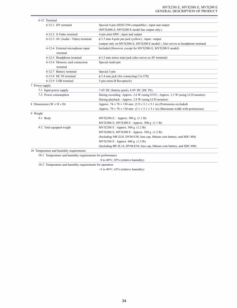
6-12 Terminal
6-12-1 DV terminal Special 4-pin (IEEE1394 compatible) ; input and output
(MVX200i E, MVX200 E model has output only.)
6-12-2 S-Video terminal 4-pin mini-DIN ; input and output
6-12-3 AV (Audio / Video) terminal φ 3.5 mm 4-pole pin jack (yellow) ; input / output
(output only on MVX200i E, MVX200 E model) ; Also serves as headphone terminal
6-12-4 External microphone input Included (However, except for MVX200i E, MVX200 E model)
terminal
6-12-5 Headphone terminal φ 3.5 mm stereo mini-jack (also serves as AV terminal)
6-12-6 Memory card connection Special multi-pin
terminal
6-12-7 Battery terminal Special 3-pin
6-12-8 DC IN terminal φ 3.4 mm jack (for connecting CA-570)
6-12-9 USB terminal 5-pin (mini-B Receptacle)
7 Power supply
7-1 Input power supply 7.4V DC (battery pack), 8.4V DC (DC IN).
7-2 Power consumption During recording : Approx. 2.6 W (using EVF) ; Approx. 3.3 W (using LCD monitor)
During playback : Approx. 2.8 W (using LCD monitor)
8 Dimensions (W × H × D) Approx. 74 × 78 × 130 mm (2.9 × 3.1 × 5.1 in) (Protrusions excluded)
Approx. 79 × 78 × 130 mm (3.1 × 3.1 × 5.1 in) (Maximum width with protrusious)
9 Weight
9-1 Body MVX250i E : Approx. 500 g (1.1 lb)
MVX200i E, MVX200 E : Approx. 500 g (1.1 lb)
9-2 Total equipped weight MVX250i E : Approx. 560 g (1.2 lb)
MVX200i E, MVX200 E : Approx. 560 g (1.2 lb)
(Including NB-2LH, DVM-E30, lens cap, lithium coin battery, and SDC-8M)
MVX250i E : Approx. 600 g (1.3 lb)
(Including BP-2L14, DVM-E30, lens cap, lithium coin battery, and SDC-8M)
10 Temperature and humidity requirements
10-1 Temperature and humidity requirements for performance
0 to 40°C, 85% (relative humidity)
10-2 Temperature and humidity requirements for operation
−5 to 40°C, 65% (relative humidity)

MVX250i E, MVX200i E, MVX200 EGENERAL DESCRIPTION OF PRODUCT
35
4. System Diagram (Common to all Models)
Fig. 2
VFL-1 Video Flash Light
VL-3 Video Light
DM-50 DirectionalStereo Microphone
CV-150F/CV-250FDV Cable
S-150 S-video Cable
MultiMediaCard
IFC-300PCU USB Cable
Canon printers with direct print function /PictBridge-compliant printers
PC Card Adapter
USB Reader/Writer
BP-900 Series Battery Pack
Stereo Microphone (commercially available)
VL-10Li Battery Video Light
WL-D83 Wireless Controller
MiniDVVideo Cassette
Digital Device
Computer
NB-2L, NB-2LH, BP-2L12, BP-2L14Battery Pack
WD-H34Wide-converter
FS-34U Filter Set
TL-H34Tele-converter
SDC-128MSD Memory Card
SS-900 Shoulder Strap
WS-20 Wrist Strap
SC-2000 Soft Carrying Case
CA-570 Compact Power Adapter
TV
VCR
CBC-NB2Car Battery Charger
CB-2LTEBattery Charger
NB-2L, NB-2LH, BP-2L12, BP-2L14Battery Pack
STV-250N Stereo Video Cable
PC-A10 SCART Adapter

MVX250i E, MVX200i E, MVX200 EGENERAL DESCRIPTION OF PRODUCT
36
MENU INDICATION PAL MODEL REMARKS
Camera mode
Zoom / Exposure correction
bar display
(displayed for approx.
four seconds after zoom operation)
Zoom bar display
Optical Zoom W T
72× digital zoom W T MVX200i E, MVX200 E : 56×
360× digital zoom W T MVX200i E, MVX200 E : 280×
Zooming is stopped W T
Zooming to telephoto end W T
Zooming to wide end W T
Exposure correction bar display
Minimum correction : -11 level
Correction default setting
Maximum correction : +11 level
Displayed by correctable range
During Full Auto No display
Image stabilizer display
The image stabilizer is ON
The image stabilizer is OFF No display
Recording mode display
SP recording
LP recording
5. Overview of viewfinder / LCD panel displays
5-1 Camera mode

MVX250i E, MVX200i E, MVX200 EGENERAL DESCRIPTION OF PRODUCT
37
MENU INDICATION PAL MODEL REMARKS
Operating mode display
Recording
Recording Pause
Playback is stopped
Cassette is ejected
+ REC Search
- REC Search
Program AE mode display
Full Auto mode is selected Always displayed
Auto mode is selected A Displayed for approx.
4 seconds and then turns OFF.
Sports mode is selected
Portrait mode is selected
Spotlight mode is selected
Surf & Snow mode is selected After displayed for approx. 4 seconds,
Low Light mode is selected only characters are displayed.
Night mode is selected
Night+ mode is selected* MVX250i E only
Super Night mode is selected* MVX250i E only
Program AE mode menu
A
Skin detail mode display
Skin detail mode is selected
Skin detail mode is not selected No display
Tape counter display
Time code display
Not entered
Zero Set Memory M
M
M
Not entered M

MVX250i E, MVX200i E, MVX200 EGENERAL DESCRIPTION OF PRODUCT
38
MENU INDICATION PAL MODEL REMARKS
EXP lock display
Minimum exposure compensation value
Default setting
Maximum exposure value
During Full Auto No display
Tape information display
Remaining tape display
Tape end
Not entered
Tape warning display flashes
Other No display
Shutter speed display When Auto mode is selected
1/50 sec is selected
1/120 sec is selected
1/250 sec is selected
1/500 sec is selected
1/1000 sec is selected
1/2000 sec is selected
Timer display
During recording
Self-timer is activated
Mirror shooting Displays large in screen center.
Displayed with right and left sides
reversed when Mirror is set to ON.

MVX250i E, MVX200i E, MVX200 EGENERAL DESCRIPTION OF PRODUCT
39
MENU INDICATION PAL MODEL REMARKS
Remaining battery level display Approx. 100% remaining
Approx. 75% remaining
Approx. 50% remaining
Approx. 25% remaining
Approx. 0% remaining,
warning display (flashes red)
Power adapter is attached No display
Focus mode display
AF is set to OFF
AF is set to ON No display
Set to infinity
Lithium coin battery warning flashes red
Condensation warning display flashes red
White balance display
Set
Indoor preset
Outdoor preset
Auto No display
Remote control code display
Code setting 1 is selected
Code setting 2 is selected
Remote controller receive OFF is selected
Card Mix display
Headphone volume display
When volume is adjusted
When volume is at off
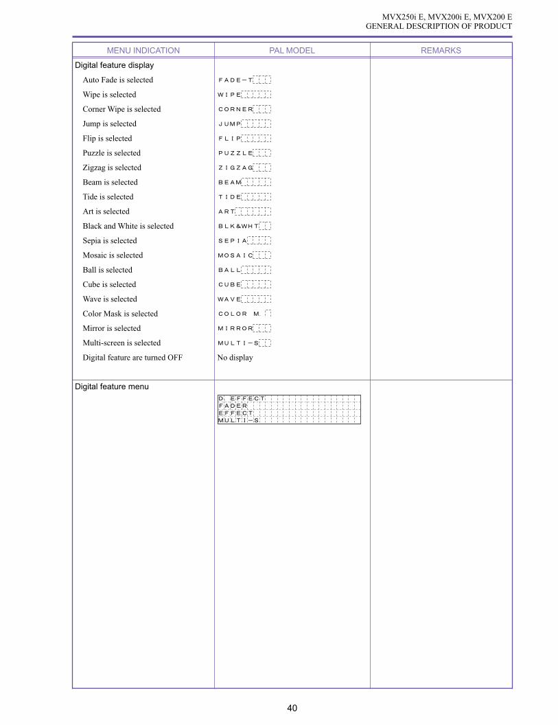
MVX250i E, MVX200i E, MVX200 EGENERAL DESCRIPTION OF PRODUCT
40
MENU INDICATION PAL MODEL REMARKS
Digital feature display
Auto Fade is selected
Wipe is selected
Corner Wipe is selected
Jump is selected
Flip is selected
Puzzle is selected
Zigzag is selected
Beam is selected
Tide is selected
Art is selected
Black and White is selected
Sepia is selected
Mosaic is selected
Ball is selected
Cube is selected
Wave is selected
Color Mask is selected
Mirror is selected
Multi-screen is selected
Digital feature are turned OFF No display
Digital feature menu

MVX250i E, MVX200i E, MVX200 EGENERAL DESCRIPTION OF PRODUCT
41
Digital feature selection
Press the DIGITAL EFFECT button.
The line where the cursor is located in the menu is displayed with a turquoise background.
The previously selected items and the corresponding settings are shown in yellow.
OFF
In Fader Selection
In Effect Selection
In Multi Screen Selection In Multi Screen Speed Selection
In Multi Screen Count Selection
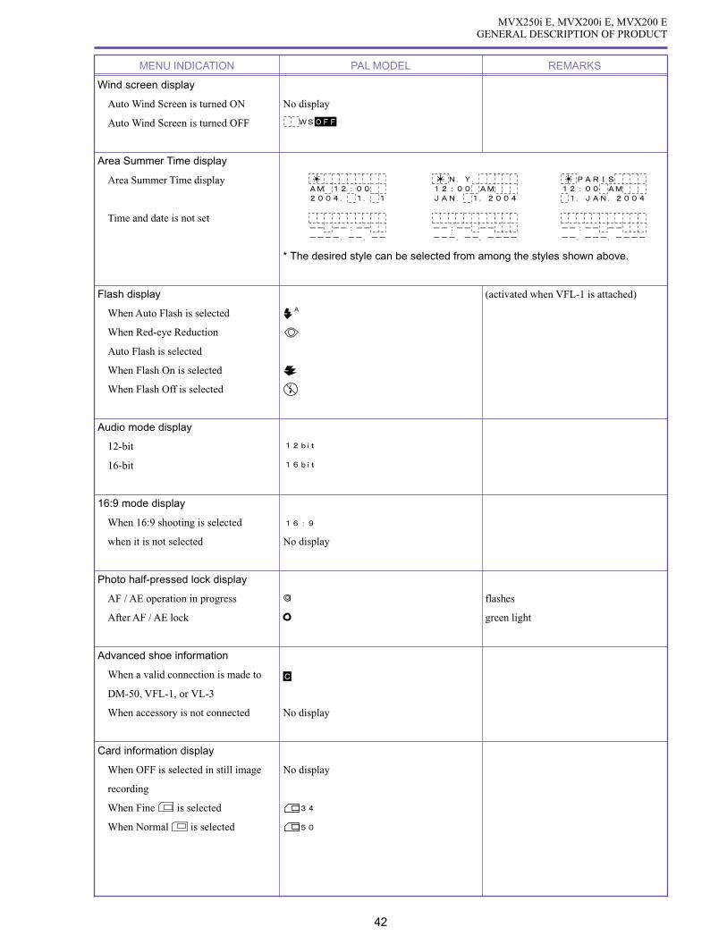
MVX250i E, MVX200i E, MVX200 EGENERAL DESCRIPTION OF PRODUCT
42
MENU INDICATION PAL MODEL REMARKS
Wind screen display
Auto Wind Screen is turned ON No display
Auto Wind Screen is turned OFF
Area Summer Time display
Area Summer Time display
Time and date is not set
* The desired style can be selected from among the styles shown above.
Flash display (activated when VFL-1 is attached)
When Auto Flash is selected
When Red-eye Reduction
Auto Flash is selected
When Flash On is selected
When Flash Off is selected
Audio mode display
12-bit
16-bit
16:9 mode display
When 16:9 shooting is selected
when it is not selected No display
Photo half-pressed lock display
AF / AE operation in progress flashes
After AF / AE lock green light
Advanced shoe information
When a valid connection is made to C
DM-50, VFL-1, or VL-3
When accessory is not connected No display
Card information display
When OFF is selected in still image No display
recording
When Fine is selected
When Normal is selected
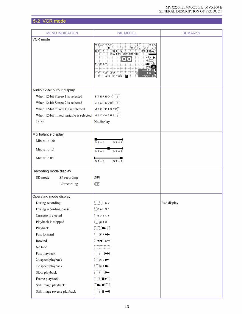
MVX250i E, MVX200i E, MVX200 EGENERAL DESCRIPTION OF PRODUCT
43
5-2 VCR mode
MENU INDICATION PAL MODEL REMARKS
VCR mode
Audio 12-bit output display
When 12-bit Stereo 1 is selected
When 12-bit Stereo 2 is selected
When 12-bit mixed 1:1 is selected
When 12-bit mixed variable is selected
16-bit No display
Mix balance display
Mix ratio 1:0
Mix ratio 1:1
Mix ratio 0:1
Recording mode display
SD mode SP recording
LP recording
Operating mode display
During recording Red display
During recording pause
Cassette is ejected
Playback is stopped
Playback
Fast forward
Rewind
No tape
Fast playback
2× speed playback
1× speed playback
Slow playback
Frame playback
Still image playback
Still image reverse playback

MVX250i E, MVX200i E, MVX200 EGENERAL DESCRIPTION OF PRODUCT
44
MENU INDICATION PAL MODEL REMARKS
Frame reverse playback
Slow reverse playback
1× SP reverse playback
2× SP reverse playback
Rewind playback
Forward date search
Reverse date search
FF return
REW return
Audio dubbing pause
Audio dubbing recording
Tape counter
Time code display
Not entered
Zero Set Memory Same as during Camera mode
Remaining tape display Same as during Camera mode
Audio dubbing /
search operation display
Audio dubbing is selected
Data search operation
When end search is selected
Other than search No display
Remaining battery level display Same as during camera mode
Lithium coin battery Warning display Same as during camera mode
Condensation warning display Same as during camera mode
Remote control code display Same as during camera mode
Digital feature display Same as during camera mode
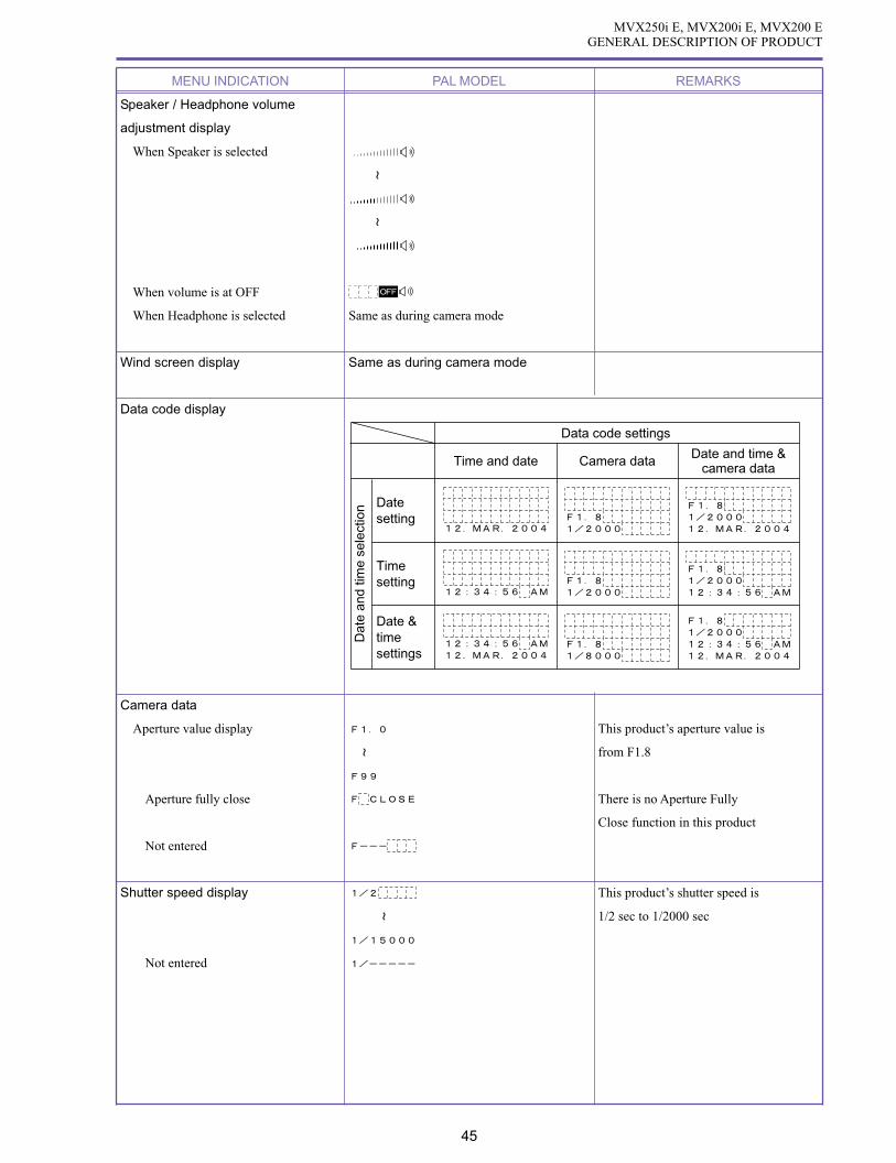
MVX250i E, MVX200i E, MVX200 EGENERAL DESCRIPTION OF PRODUCT
45
MENU INDICATION PAL MODEL REMARKS
Speaker / Headphone volume
adjustment display
When Speaker is selected
When volume is at OFF
When Headphone is selected Same as during camera mode
Wind screen display Same as during camera mode
Data code display
Data code settings
Time and date Camera data Date and time &camera data
Time setting
Date setting
Date & time settings
Dat
e an
d tim
e se
lect
ion
Camera data
Aperture value display This product’s aperture value is
from F1.8
Aperture fully close There is no Aperture Fully
Close function in this product
Not entered
Shutter speed display This product’s shutter speed is
1/2 sec to 1/2000 sec
Not entered

MVX250i E, MVX200i E, MVX200 EGENERAL DESCRIPTION OF PRODUCT
46
MENU INDICATION PAL MODEL REMARKS
Time display
Time setting is selected
Not entered
Time and time setting are selected
Not entered
Data display
Not entered
Audio mode display
Audio mode display Same as during camera mode
Audio input display
Audio input terminal is selected
Microphone terminal is selected
16:9 mode display
16:9 tape playback
Normal tape play back No display
Advanced shoe information
When a valid connection is made to C
DM-50, VFL-1, or VL-3
When accessory is not connected No display
DV input display
AV DV signal conversion is selected
Other No display
Playback zoom display

MVX250i E, MVX200i E, MVX200 EGENERAL DESCRIPTION OF PRODUCT
47
5-3 Card / Camera mode
MENU INDICATION PAL MODEL REMARKS
Card/Camera mode
Zoom/Exposure correction display
Zoom/Exposure correction display Same as Camera mode
(except that Digital zoom is 72/64/56× only)
Over exposure warning (flashes) Caution is indicated when F11 or higher
Continuous shot / AEB mode display
When Continuous Shooting mode
is selected
When fast continuous shot mode
is selected
When AEB mode is selected
When Single Shot mode is selected No display
Card recording quality display
Program AE mode display Same as during Camera mode
Skin detail mode display Same as during Camera mode
Stitch Assist quantity display Clockwise
Counter-clockwise
Image stabilizer warning display Displayed when the shutter speed is
1/60 second or less
Card access display Writing and reading

MVX250i E, MVX200i E, MVX200 EGENERAL DESCRIPTION OF PRODUCT
48
MENU INDICATION PAL MODEL REMARKS
Card remaining display
No card (flashes red)
9999 or more images can be recorded
99 images can be recorded
5 images can be recorded
Yellow display
1 image scan be recorded
EXP lock display Same as during Camera/Tape mode
Self-timer display Same as during Camera mode
Still image size display
1280 × 768 is selected
640 × 480 is selected
Motion video size display
320 × 240 is selected
160 × 120 is selected
Shutter speed display
Focus mode display Same as during Camera mode
Remaining battery level display Same as during Camera mode
White balance display Same as during Camera mode
AF frame display
AF priority Center only during green mode
After three seconds, the green display
section only appears white.
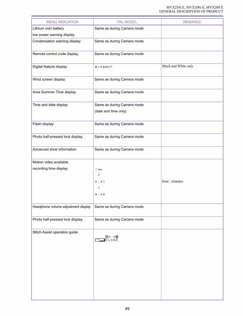
MVX250i E, MVX200i E, MVX200 EGENERAL DESCRIPTION OF PRODUCT
49
MENU INDICATION PAL MODEL REMARKS
Lithium coin battery Same as during Camera mode
low power warning display
Condensation warning display Same as during Camera mode
Remote control code display Same as during Camera mode
Digital feature display Black and White only
Wind screen display Same as during Camera mode
Area Summer Time display Same as during Camera mode
Time and date display Same as during Camera mode
(date and time only)
Flash display Same as during Camera mode
Photo half-pressed lock display Same as during Camera mode
Advanced shoe information Same as during Camera mode
Motion video available
recording time display
hour : minutes
Headphone volume adjustment display Same as during Camera mode
Photo half-pressed lock display Same as during Camera mode
Stitch Assist operation guide

MVX250i E, MVX200i E, MVX200 EGENERAL DESCRIPTION OF PRODUCT
50
5-4 Card Playback mode
5-4-1 Still image Playback
MENU INDICATION PAL MODEL REMARKS
Card Playback mode (Still images)
Title display
Slide show
Card playback
Send designation mark display
Print mark display
Protect mark display
DCF file name display
Directory number-File number
PC USB connection display
When not connected No display
Card access display
Image number display
No card Red flashing display
Checking number of images
recorded on card
0 recorded images
9th of 99 recorded images
99th of 99 recorded images
9999th of 9999 recorded images

MVX250i E, MVX200i E, MVX200 EGENERAL DESCRIPTION OF PRODUCT
51
MENU INDICATION PAL MODEL REMARKS
Data code display Same as during VCR mode
(date and time only)
Playback zoom operation guide display Same as during VCR playback mode
Slideshow operation guide display
5-4-2 Motion video (Motion JPEG) Playback
Motion video
(Motion JPEG)
Card information display
No card Red flashing display
Checking number of images recorded
on card
0 recorded images
9th of 99 recorded images
99th of 99 recorded images
9999th of 9999 recorded images
Motion video size display
Speaker/headphone volume adjustment Same as during VCR mode
Operating mode display
Playback
Playback pause
Data code display Same as during VCR mode
(date and time only)
Total playback time display
Lap time display

MVX250i E, MVX200i E, MVX200 EGENERAL DESCRIPTION OF PRODUCT
52
5-4-3 Direct printing
MENU INDICATION PAL MODEL REMARKS
Card Playback mode
(Direct printing)
Printer connected display
CP Direct compatible printer SET
PictBridge compatible printer SET
Bubble Jet Direct compatible printer SET

53
MVX250i E, MVX200i E, MVX200 EGENERAL DESCRIPTION OF PRODUCTUCT
5-5 Menu Display
The menu display has Camera mode, VCR mode, Card/Camera mode, and Card Playback mode.
Camera Mode
MAIN MENU ITEM SUB MENU ITEM SETTINGS DEFAULT BACKUP
CARD MIX Switches to Card mix selection screen
CAMERA SET UP SHUTTER AUTO AUTO Lithium battery
1/50
1/120
1/250
1/500
1/1000
1/2000
A. SL SHUTTER ON ON Lithium battery
OFF
D. ZOOM *1 OFF Lithium battery
72× / 64× / 56× 72× / 64× / 56×360× / 320× / 280×
IMAGE STAB ON ON Lithium battery
OFF
16 : 9 ON OFF Lithium battery
OFF
WHIT BAL. AUTO AUTO Lithium battery
SET
INDOOR
OUTDOOR
FLASH *2 AUTO AUTO Lithium battery
RED-EYE
FLASH ON
FLASH OFF
AF AST LAMP *2 AUTO AUTO Lithium battery
OFF
NIGHT MODE *3 NIGHT Lithium batteryNIGHT+
S.NIGHT
SKIN DETAIL SOFT NORMAL Reset by turning power off
NORMAL
PHOTO REC *2 OFF
FINE Lithium battery
NORMAL
RETURN
VCR SET UP REC MODE SP SP Lithium battery
LP
AV/PHONES AV AV Lithium battery
PHONES
RETURN

54
MVX250i E, MVX200i E, MVX200 EGENERAL DESCRIPTION OF PRODUCTUCT
MAIN MENU ITEM SUB MENU ITEM SETTINGS DEFAULT BACKUP
AUDIO SET UP WIND SCREEN AUTO AUTO Lithium battery
OFF
AUDIO MODE 16 bit 12 bit Lithium battery
12 bit
VOLUME Lithium battery
RETURN
DISPLAY SET UP/ BRIGHTNESS Lithium battery
LCD MIRROR ON ON Lithium battery
OFF
TV SCREEN ON ON Lithium battery
OFF
D/T DISPLAY ON OFF Lithium battery
OFF
LANGUAGE DEUTSCH ENGLISH
ENGLISH
ESPAÑOL
FRANÇAIS
ITALIANO
PyCCKИИИИИЙЙЙЙЙ
中文
日本語
DATE FORMAT 2004. 1. 1 1. JAN. 2004
AM 12:00 12:00 AM
JAN. 1, 2004
12:00 AM
1. JAN. 2004
12:00 AM
DEMO MODE ON ON Lithium battery
OFF
RETURN
SYSTEM WL. REMOTE Lithium battery
OFF
BEEP ON ON Lithium battery
OFF
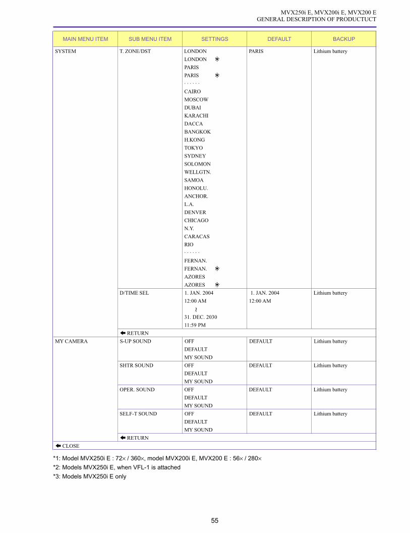
55
MVX250i E, MVX200i E, MVX200 EGENERAL DESCRIPTION OF PRODUCTUCT
MAIN MENU ITEM SUB MENU ITEM SETTINGS DEFAULT BACKUP
SYSTEM T. ZONE/DST LONDON PARIS Lithium battery
LONDON
PARIS
PARIS
· · · · · ·
CAIRO
MOSCOW
DUBAI
KARACHI
DACCA
BANGKOK
H.KONG
TOKYO
SYDNEY
SOLOMON
WELLGTN.
SAMOA
HONOLU.
ANCHOR.
L.A.
DENVER
CHICAGO
N.Y.
CARACAS
RIO
· · · · · ·
FERNAN.
FERNAN.
AZORES
AZORES
D/TIME SEL 1. JAN. 2004 1. JAN. 2004 Lithium battery
12:00 AM 12:00 AM
31. DEC. 2030
11:59 PM
RETURN
MY CAMERA S-UP SOUND OFF DEFAULT Lithium battery
DEFAULT
MY SOUND
SHTR SOUND OFF DEFAULT Lithium battery
DEFAULT
MY SOUND
OPER. SOUND OFF DEFAULT Lithium battery
DEFAULT
MY SOUND
SELF-T SOUND OFF DEFAULT Lithium battery
DEFAULT
MY SOUND
RETURN
CLOSE
*1: Model MVX250i E : 72× / 360×, model MVX200i E, MVX200 E : 56× / 280×*2: Models MVX250i E, when VFL-1 is attached
*3: Models MVX250i E only
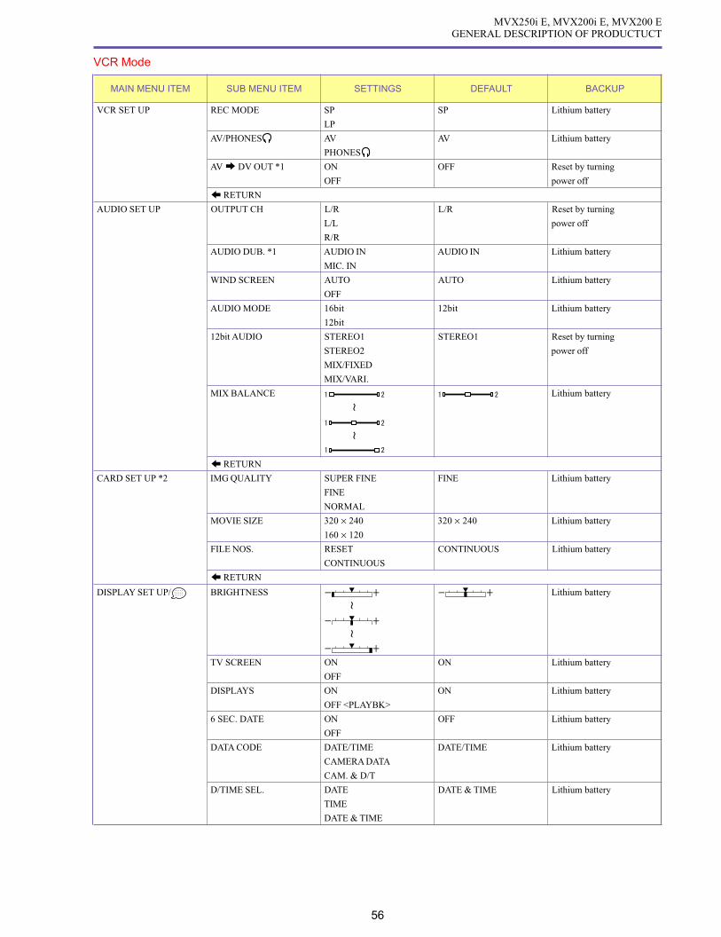
56
MVX250i E, MVX200i E, MVX200 EGENERAL DESCRIPTION OF PRODUCTUCT
VCR Mode
MAIN MENU ITEM SUB MENU ITEM SETTINGS DEFAULT BACKUP
VCR SET UP REC MODE SP SP Lithium battery
LP
AV/PHONES AV AV Lithium battery
PHONES
AV DV OUT *1 ON OFF Reset by turning
OFF power off
RETURN
AUDIO SET UP OUTPUT CH L/R L/R Reset by turning
L/L power off
R/R
AUDIO DUB. *1 AUDIO IN AUDIO IN Lithium battery
MIC. IN
WIND SCREEN AUTO AUTO Lithium battery
OFF
AUDIO MODE 16bit 12bit Lithium battery
12bit
12bit AUDIO STEREO1 STEREO1 Reset by turning
STEREO2 power off
MIX/FIXED
MIX/VARI.
MIX BALANCE Lithium battery
RETURN
CARD SET UP *2 IMG QUALITY SUPER FINE FINE Lithium battery
FINE
NORMAL
MOVIE SIZE 320 × 240 320 × 240 Lithium battery
160 × 120
FILE NOS. RESET CONTINUOUS Lithium battery
CONTINUOUS
RETURN
DISPLAY SET UP/ BRIGHTNESS Lithium battery
TV SCREEN ON ON Lithium battery
OFF
DISPLAYS ON ON Lithium battery
OFF <PLAYBK>
6 SEC. DATE ON OFF Lithium battery
OFF
DATA CODE DATE/TIME DATE/TIME Lithium battery
CAMERA DATA
CAM. & D/T
D/TIME SEL. DATE DATE & TIME Lithium battery
TIME
DATE & TIME

57
MVX250i E, MVX200i E, MVX200 EGENERAL DESCRIPTION OF PRODUCTUCT
MAIN MENU ITEM SUB MENU ITEM SETTINGS DEFAULT BACKUP
DISPLAY SET UP/ LANGUAGE DEUTSCH ENGLISH
ENGLISH
ESPAÑOL
FRANÇAIS
ITALIANO
PyCCKИИИИИЙЙЙЙЙ
中文
日本語
DATE FORMAT 2004. 1. 1 1. JAN. 2004
AM 12:00 12:00 AM
JAN. 1, 2004
12:00 AM
1. JAN. 2004
12:00 AM
RETURN
SYSTEM WL. REMOTE Lithium battery
OFF
BEEP ON ON Lithium battery
OFF
T. ZONE/DST LONDON PARIS Lithium battery
LONDON
PARIS
PARIS
· · · · · ·
CAIRO
MOSCOW
DUBAI
KARACHI
DACCA
BANGKOK
H.KONG
TOKYO
SYDNEY
SOLOMON
WELLGTN.
SAMOA
HONOLU.
ANCHOR.
L.A.
DENVER
CHICAGO
N.Y.
CARACAS
RIO
· · · · · ·
FERNAN.
FERNAN.
AZORES
AZORES
D/TIME SEL JAN. 1, 2004 1. JAN. 2004 Lithium battery
12:00 AM 12:00 AM
31. DEC. 2030
11:59 PM
RETURN

58
MVX250i E, MVX200i E, MVX200 EGENERAL DESCRIPTION OF PRODUCTUCT
MAIN MENU ITEM SUB MENU ITEM SETTINGS DEFAULT BACKUP
MY CAMERA SHTR SOUND OFF DEFAULT Lithium battery
DEFAULT
MY SOUND
S-UP SOUND OFF DEFAULT Lithium battery
DEFAULT
MY SOUND
OPER. SOUND OFF DEFAULT Lithium battery
DEFAULT
MY SOUND
SELF-T SOUND OFF DEFAULT Lithium battery
DEFAULT
MY SOUND
RETURN
CLOSE
*1 : Excluding model MVX200 E

59
MVX250i E, MVX200i E, MVX200 EGENERAL DESCRIPTION OF PRODUCTUCT
Card / Camera Mode
MAIN MENU ITEM SUB MENU ITEM SETTINGS DEFAULT BACKUP
CAMERA SET UP SHUTTER AUTO AUTO Lithium battery
1/50
1/120
1/250
A. SL SHUTTER ON ON Lithium battery
OFF
D. ZOOM OFF OFF Lithium battery
72× / 64× / 56×WHIT BAL. AUTO AUTO Lithium battery
SET
INDOOR
OUTDOOR
FLASH *1 AUTO AUTO Lithium battery
RED-EYE
FLASH ON
FLASH OFF
AF AST LAMP *1 AUTO AUTO Lithium battery
OFF
FOCUS PRI. ON ON Lithium battery
OFF
ND AUTO AUTO Lithium battery
OFF
NIGHT MODE *2 NIGHT NIGHT+ Lithium batteryNIGHT+
S.NIGHT
SKIN DETAIL SOFT NORMAL Reset by turning power off
NORMAL
REVIEW OFF 2sec Lithium battery
2sec
4sec
6sec
8sec
10sec
RETURN
CARD SET UP IMG QUALITY SUPER FINE FINE Lithium battery
FINE
NORMAL
IMG SIZE 1280 × 960 1280 × 960 Lithium battery
640 × 480
MOVIE SIZE 320 × 240 320 × 240 Lithium battery
160 × 120
FILE NOS. RESET CONTINUOS Lithium battery
CONTINUOS
RETURN
VCR SET UP AV/PHONES AV AV Reset by turning power off
PHONES
RETURN
AUDIO SET UP WIND SCREEN ON OFF Lithium battery
OFF
VOLUME Lithium battery
RETURN

60
MVX250i E, MVX200i E, MVX200 EGENERAL DESCRIPTION OF PRODUCTUCT
MAIN MENU ITEM SUB MENU ITEM SETTINGS DEFAULT BACKUP
DISPLAY SET UP/ BRIGHTNESS Lithium battery
LCD MIRROR ON ON Lithium battery
OFF
TV SCREEN ON ON Lithium battery
OFF
D/T DISPLAY ON OFF Lithium battery
OFF
LANGUAGE DEUTSCH ENGLISH
ENGLISH
ESPAÑOL
FRANÇAIS
ITALIANO
PyCCKИИИИИЙЙЙЙЙ
中文
日本語
DATE FORMAT 2004. 1. 1 1. JAN. 2004
AM 12:00 12:00 AM
JAN. 1, 2004
12:00 AM
1. JAN. 2004
12:00 AM
DEMO MODE ON ON Lithium battery
OFF
RETURN
SYSTEM WL. REMOTE Lithium battery
OFF
BEEP ON ON Lithium battery
OFF

61
MVX250i E, MVX200i E, MVX200 EGENERAL DESCRIPTION OF PRODUCTUCT
*1 : Displayed only when VFL-1 is attached, Models MVX250i E only*2 : Models MVX250i E only
MAIN MENU ITEM SUB MENU ITEM SETTINGS DEFAULT BACKUP
SYSTEM T. ZONE/DST LONDON PARIS Lithium battery
LONDON
PARIS
PARIS
· · · · · ·
CAIRO
MOSCOW
DUBAI
KARACHI
DACCA
BANGKOK
H.KONG
TOKYO
SYDNEY
SOLOMON
WELLGTN.
SAMOA
HONOLU.
ANCHOR.
L.A.
DENVER
CHICAGO
N.Y.
CARACAS
RIO
· · · · · ·
FERNAN.
FERNAN.
AZORES
AZORES
D/TIME SEL 1. JAN. 2004 1. JAN. 2004 Lithium battery
12:00 AM 12:00 AM
31. DEC. 2030
11:59 PM
RETURN
MY CAMERA S-UP SOUND OFF DEFAULT Lithium battery
DEFAULT
MY SOUND
SHTR SOUND OFF DEFAULT Lithium battery
DEFAULT
MY SOUND
OPER. SOUND OFF DEFAULT Lithium battery
DEFAULT
MY SOUND
SELF-T SOUND OFF DEFAULT Lithium battery
DEFAULT
MY SOUND
RETURN
CLOSE

62
MVX250i E, MVX200i E, MVX200 EGENERAL DESCRIPTION OF PRODUCTUCT
Card Playback Mode (Card/VCR mode)
MAIN MENU ITEM SUB MENU ITEM SETTINGS DEFAULT BACKUP
CARD OPERATIONS PRINT ORDERS Switches to erase all print designations screen
(for single screen) ALL ERASE
TRANSFER ORDERS Switches to erase send designations screen
ALL ERASE
IMAGE ERASE CANCEL None
SINGLE
ALL
FORMAT CANCEL None
EXECUTE
RETURN
CARD OPERATIONS PROTECT Switches to image protect screen
(for index screen)
PRINT ORDER Switches to print designations screen
TRANSFER Switches to send designations screen
ORDER
RETURN
VCR SET UP AV/PHONES AV AV Reset by turning power off
PHONES
RETURN
DISPLAY SET UP/ BRIGHTNESS Lithium battery
TV SCREEN ON ON Lithium battery
OFF
DISPLAY ON ON Lithium battery
OFF <PLAYBK>
D/TIME SEL. DATE DATE & TIME Lithium battery
TIME
DATE & TIME
LANGUAGE DEUTSCH ENGLISH
ENGLISH
ESPAÑOL
FRANÇAIS
ITALIANO
PyCCKИИИИИЙЙЙЙЙ
中文
日本語
DATE FORMAT 2004. 1. 1 1. JAN. 2004
AM 12:00 12:00 AM
JAN. 1, 2004
12:00 AM
1. JAN. 2004
12:00 AM
RETURN
SYSTEM WL. REMOTE Lithium battery
OFF
BEEP ON ON Lithium battery
OFF

63
MVX250i E, MVX200i E, MVX200 EGENERAL DESCRIPTION OF PRODUCTUCT
MAIN MENU ITEM SUB MENU ITEM SETTINGS DEFAULT BACKUP
SYSTEM T. ZONE/DST LONDON PARIS Lithium battery
LONDON
PARIS
PARIS
· · · · · ·
CAIRO
MOSCOW
DUBAI
KARACHI
DACCA
BANGKOK
H.KONG
TOKYO
SYDNEY
SOLOMON
WELLGTN.
SAMOA
HONOLU.
ANCHOR.
L.A.
DENVER
CHICAGO
N.Y.
CARACAS
RIO
· · · · · ·
FERNAN.
FERNAN.
AZORES
AZORES
D/TIME SEL 1. JAN. 2004 1. JAN. 2004 Lithium battery
12:00 AM 12:00 AM
31. DEC. 2030
11:59 PM
RETURN
MY CAMERA CREATE START-UP IMAGE Switches to startup image creation screen
SEL. S-UP IMG. OFF CANON LOGO Lithium battery
CANON LOGO
MY PICTURE
S-UP SOUND OFF DEFAULT Lithium battery
DEFAULT
MY SOUND
SHTR SOUND OFF DEFAULT Lithium battery
DEFAULT
MY SOUND
OPER. SOUND OFF DEFAULT Lithium battery
DEFAULT
MY SOUND
SELF-T SOUND OFF DEFAULT Lithium battery
DEFAULT
MY SOUND
RETURN
CLOSE
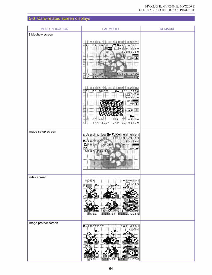
MVX250i E, MVX200i E, MVX200 EGENERAL DESCRIPTION OF PRODUCT
64
MENU INDICATION PAL MODEL REMARKS
Slideshow screen
Image setup screen
Index screen
Image protect screen
5-6 Card-related screen displays
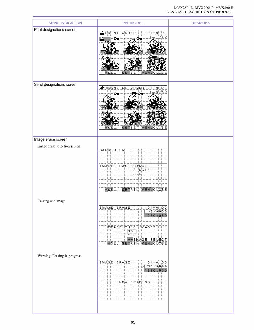
MVX250i E, MVX200i E, MVX200 EGENERAL DESCRIPTION OF PRODUCT
65
MENU INDICATION PAL MODEL REMARKS
Print designations screen
Send designations screen
Image erase screen
Image erase selection screen
Erasing one image
Warning: Erasing in progress

MVX250i E, MVX200i E, MVX200 EGENERAL DESCRIPTION OF PRODUCT
66
MENU INDICATION PAL MODEL REMARKS
Image erase screen
Erasing all images
Format screen
Format execution confirmation screen
Format execution screen

MVX250i E, MVX200i E, MVX200 EGENERAL DESCRIPTION OF PRODUCT
67
MENU INDICATION PAL MODEL REMARKS
Card mix selection screen
Mix type setting screen
Animation type setting screen
Mix level setting screen

MVX250i E, MVX200i E, MVX200 EGENERAL DESCRIPTION OF PRODUCT
68
MENU INDICATION PAL MODEL REMARKS
Stitch assist screen
My camera settings
My camera settings screen
Startup image creation screen
Recording position selection
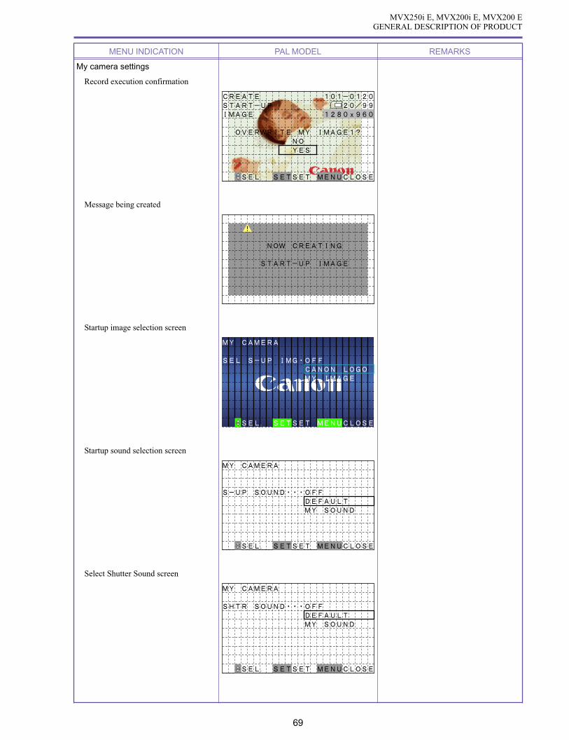
MVX250i E, MVX200i E, MVX200 EGENERAL DESCRIPTION OF PRODUCT
69
MENU INDICATION PAL MODEL REMARKS
My camera settings
Record execution confirmation
Message being created
Startup image selection screen
Startup sound selection screen
Select Shutter Sound screen

MVX250i E, MVX200i E, MVX200 EGENERAL DESCRIPTION OF PRODUCT
70
MENU INDICATION PAL MODEL REMARKS
My camera settings
Operation sound selection screen
Self-timer sound selection screen
PC connection screen
During USB connection
During IEEE1394 connection

MVX250i E, MVX200i E, MVX200 EGENERAL DESCRIPTION OF PRODUCT
71
MENU INDICATION PAL MODEL
Direct print setting screen
Direct print setting initial screen
Print selection screen PC Direct (CP-10/100) and PictBridge compatible printer
BJ Direct (Pixus 50i) compatible printers (CP-200/300, Pixus 990i)
BORDERED
CARD#1
STYLE
PRINT CANCEL
DEFAULT
DEFAULT
DEFAULT
TRIMMING
1 COPIES
CANCEL
PAPER
OFF
OFF
1 COPIES
TRIMMINGPRINT
Cancel print screen
STOPSTOP
NOW PRINTING (1/3)NOW PRINTING (1/3)
CARD#1
BORDERED
DEFAULT
DEFAULT
DEFAULT
Cancel selection screen
BORDERED
CARD#1
STYLE
PRINT CANCEL
DEFAULT
DEFAULT
DEFAULT
CANCEL
PAPER
OFF
OFF
1 COPIES
TRIMMINGPRINT
TRIMMING
1 COPIES
5-7 Direct print setting screen

MVX250i E, MVX200i E, MVX200 EGENERAL DESCRIPTION OF PRODUCT
72
MENU INDICATION PAL MODEL
Direct print setting screen
Quantity setting screen PC Direct (CP-10/100) and PictBridge compatible printer
BJ Direct (Pixus 50i) compatible printers (CP-200/300, Pixus 990i)
BORDERED
CARD#1
STYLE
TRIMMING
CANCEL
3 COPIES
DEFAULT
DEFAULT
DEFAULT
CANCEL
PAPER
OFF
OFF
3 COPIES
TRIMMINGPRINT
Trimming setting screen
BORDERED
CARD#1
STYLE
PRINT CANCEL
DEFAULT
DEFAULT
DEFAULT
TRIMMING
1 COPIES
CANCEL
PAPER
OFF
OFF
1 COPIES
TRIMMINGPRINT

MVX250i E, MVX200i E, MVX200 EGENERAL DESCRIPTION OF PRODUCT
73
MENU INDICATION PAL MODEL
Direct print setting screen
Paper setting, PC Direct (CP-10/100) and PictBridge compatible printer
paper size setting screen BJ Direct (Pixus 50i) compatible printers (CP-200/300, Pixus 990i)
STYLE
PAPER
CARD#1
MENU
PAPER
CARD#1
STYLE
MENU
PAPER
CARD#2
STYLE
MENU
MENU SET
MENU SET
PAPERSIZE
PAPERSIZE
PAPERSIZE
NEXTCANCEL
MENU SET NEXTCANCEL
NEXTCANCEL
CARD#1
CARD#2
CARD#3
8.5"x11"
A4
DEFAULT
CARD#1
CARD#2
CARD#3
8.5"x11"
A4
DEFAULT
CARD#1
CARD#2
CARD#3
8.5"x11"
A4
DEFAULT
* Only paper sizes supported by the
printer can be selected from among
Default, L, 2L, Postcard, Card, 4 ×
6, Letter, Letter, A4, Roll (L), Roll
(2L), Roll (A4), and 5 × 7.
* Camera Direct compatible BJ print-
ers only.

MVX250i E, MVX200i E, MVX200 EGENERAL DESCRIPTION OF PRODUCT
74
MENU INDICATION PAL MODEL
Direct print setting screen
Paper type setting screen PC Direct (CP-10/100) and PictBridge compatible printer
BJ Direct (Pixus 50i) compatible printers (CP-200/300, Pixus 990i)
MENU SET NEXTPREVIOUS
PAPERTYPE
PHOTOFAST PHOTO DEFAULT
MENU SET NEXTPREVIOUS
PAPERTYPE
PHOTOFAST PHOTO DEFAULT
MENU SET NEXTPREVIOUS
PAPERTYPE
PHOTOFAST PHOTO DEFAULT
No function
* Only paper types supported by the se-
lected paper size can be selected from
among Default, Photo Paper and Fast
Photo Paper.

MVX250i E, MVX200i E, MVX200 EGENERAL DESCRIPTION OF PRODUCT
75
MENU INDICATION PAL MODEL
Direct print setting screen
Borders/no borders setting, PC Direct (CP-10/100) and PictBridge compatible printer
8-of-1 screen layout selection screen BJ Direct (Pixus 50i) compatible printers (CP-200/300, Pixus 990i)
BORDERS
BORDERED
MENU
STYLE
BORDERS
BORDERLESS
STYLE
MENU
BORDERS
BORDERED
STYLE
MENU
MENU SET NEXTPREVIOUS
MENU SET NEXTPREVIOUS
MENU SET NEXTPREVIOUS
LAYOUT
LAYOUT
LAYOUTBORDERLESSBORDEREDDEFAULT
BORDERLESSBORDEREDDEFAULT
BORDERLESSBORDEREDDEFAULT
Split screen (CP-10/100) and
8-of-1 screen layout setting
(CP-200/CP-300)
MENU MENU SET NEXTPREVIOUS
LAYOUT
BORDERLESSBORDERED
DEFAULT
IMAGE
MULTIPLE
STYLE

MVX250i E, MVX200i E, MVX200 EGENERAL DESCRIPTION OF PRODUCT
76
MENU INDICATION PAL MODEL
Print designations screen PC Direct (CP-10/100) and PictBridge compatible printer
BJ Direct (Pixus 50i) compatible printers (CP-200/300, Pixus 990i)
STYLE
RESUME
O K CANCEL
PRINT ALL MARKED IMAGES
99 CARD #1BORDER-LESS
RESUME CANCEL
PAPER
PRINT ALL MARKED IMAGES
98 OFF
OFFDEFAULT
DEFAULT
DEFAULT
Cancel print screen
99
STOP
NOW PRINTING(1/99)
CARD #1
BORDER-LESS 98
STOP
NOW PRINTING(1/98)
OFF
OFFDEFAULT
DEFAULT
BORDERLESS
Restart print screen
98
98 IMAGES REMAINING STOP PRINTING?
CARD
BORDER-LESS 98
98 IMAGES REMAININGSTOP PRINTING?
OFF
OFFDEFAULT
DEFAULT
BORDERLESS
OK CANCEL OK CANCEL
Style setting screen
CARD #1BORDER-LESSSTYLE
RESUME
O K CANCEL
CHANGE PRINT STYLE
99
No function
5-8 Print designations

MVX250i E, MVX200i E, MVX200 EGENERAL DESCRIPTION OF PRODUCT
77
5-9 Warning displays
COPYRIGHT PROTECTED PLAYBACK IS RESTRICTED• When copy-protected tape is played.
COPYRIGHT PROTECTED DUBBING RESTRICTED• When copy protection information is detected during DV input or LINE input, or when the signal output from the television or
VCR is garbled during analog input.
SET THE TIME ZONE, DATE AND TIME• When the power is turned on without setting the area and/or time and date.
REMOVE THE CASSETTE• When a cassette is inserted while there is a mechanical error or condensation in the unit.
CHECK THE DV INPUT• When “REC” is pressed in a mode that allows transition to REC, without a connection to DV input, or in a condition where the
connected DV input cannot be recognized.
CHANGE THE BATTERY PACK• When the battery power is low.
CONDENSATION HAS BEEN DETECTED• When condensation is detected (if a cassette is inserted, a “REMOVE THE CASSETTE” message appears).
THE TAPE IS SET FOR ERASURE PREVENTION• When “REC” is pressed in a mode that allows transition to REC in VCR mode, if the cassette is set for erasure prevention. In
Camera mode, when the power is turned ON, when the “Start/Stop” button is pressed, and when a cassette is inserted.
TAPE END• When the tape end is detected, or when a key (FF, PLAY, etc.) which drives the tape forward is pressed in a mode that allows
transition to forward driving during the detection process.
CHECK THE CASSETTE [REC MODE]• When the Audio Dubbing or AV Insert button is pressed at a tape position recorded in LP, or when LP mode is detected during
Audio Dubbing.
CHECK THE CASSETTE [AUDIO MODE]• When the Audio Dubbing button is pressed at a tape position with 16-bit or 4-channel simultaneous recording, or when 16-bit
mode or 4-channel simultaneous recording mode is detected during audio dubbing.
CHECK THE CASSETTE [BLANK]• When a blank tape area is detected during Audio Dubbing.
CHECK THE CASSETTE

MVX250i E, MVX200i E, MVX200 EGENERAL DESCRIPTION OF PRODUCT
78
HEADS DIRTY, USE CLEANING CASSETTE• When a print head is clogged.
CARD ERROR• When a card error occurs and data cannot be recorded on the card.
CARD FULL• When the card is full.
NAMING ERROR• When the maximum number of file numbers and directory numbers are created.
UNIDENTIFIABLE IMAGE• When an attempt is made to playback an image in an unplayable format, an incompatible JPEG image, or an image with corrupt
data.
PRINT ORDER ERROR• When there are too many print marks (100 or more), or when a mark file cannot be edited.
NO CARD• When there is no card in the camcorder socket.
NO IMAGES• When there are no images to be played in the card.
THE CARD IS SET FOR ERASURE PREVENTION• When an attempt is made to record on an SD card set for erasure prevention, in a mode that allows card recording (VCR mode,
Card Recording mode).
NOW CREATING START-UP IMAGE• The startup screen is being written to flash memory.
THIS IMAGE CANNOT BE USED AS START-UP IMAGE
IN CARD POSITION• When Start/Stop button is pressed in the Camera mode.
THIS IMAGE CANNOT BE RECORDED• (Models MVX250i E)
DIFFERENT CARD FORMAT• When the card format is not supported by the camcorder.

MVX250i E, MVX200i E, MVX200 EGENERAL DESCRIPTION OF PRODUCT
79
PAPER ERROR• When there is a problem with the paper.
NO PAPER• When the paper has not been inserted into the printer properly or there is no paper in the printer
PAPER JAM• When the paper has jammed during printing.
NO INK• When the ink has not been installed properly or the ink has run out.
LOW INK LEVEL• When there is not much ink left.
WASTE TANK FULL• When the waste ink tank is full.
CANNOT PRINT !• When trying to print a still image recorded by a different camcorder, a still image in a different format, or a still image that was
loaded to a computer and edited.
COULD NOT PRINT * IMAGES• When trying to use the DPOF settings to print a * still images recorded by a different camcorder, a still images in a different
format, or a still images that was loaded to a computer and edited.
SET PRINT ORDER• When trying to use the PRINT command in the Card Playback menu to print a still image not designated for printing.
CANNOT TRIM• When an attempt has been made to trim still images with a 160 × 120 image size. Alternatively, when an attempt has been made
to trim images whose aspect ratio differs significantly from 4:3.
READJUST TRIMMING• When the “Style” setting has been changed after trimming was set.
PRINTER ERROR• When trouble has occurred in the printer.
COMMUNICATION ERROR• When an error has occurred during communication.
PRINTER IN USE

MVX250i E, MVX200i E, MVX200 EGENERAL DESCRIPTION OF PRODUCT
80
PRINTER WARMING UP• When the printer is getting ready.
PAPER LEVER ERROR• When the printer’s paper lever is not at the correct position.
PRINTER COVER OPEN• When the printer’s cover is open.
NO PRINTHEAD• When the ink head has not been installed in the printer.
FIRMWARE UPDATED
INCOMPATIBLE PEPAR SIZE• When an unavailable paper size was selected in the paper size menu after displaying the paper size menu and changing the
settings at the printer side.
CHECK PRINT SETTINGS• When the printer setting status displays the current recording value and the Easy Direct button was pressed even though this
value cannot be used by PictBridge when the printer is connected.
PRINT ERROR• When a printer error occurs due to unknown reason.
SEND DESIGNATION ERROR
TOO MANY IMAGES DISCONNECT CABLE
CANNOT TRANSFER!• When the Easy Direct button was pressed when a motion video was displayed (SET UP icon and the icons to its right gray out,
and the Easy Direct button lights up) while “PC Wallpaper” was set.

TECHNICAL DESCRIPTON
CONTENTS
1. P.C.B. Functions --------------------------------------------------------------------------------------------------------------------------------- 1
2. Power Supply Circuit --------------------------------------------------------------------------------------------------------------------------- 3
2-1 Startup of Power Supply ---------------------------------------------------------------------------------------------------------------- 3
2-2 Power Fuses ------------------------------------------------------------------------------------------------------------------------------- 5
2-3 Power Supply Circuits ------------------------------------------------------------------------------------------------------------------- 6
3. Built-in Charger Circuit ------------------------------------------------------------------------------------------------------------------------- 7
3-1 Outline ------------------------------------------------------------------------------------------------------------------------------------- 7
3-2 Operation at Charging ------------------------------------------------------------------------------------------------------------------- 8
3-2-1 Conditions to Start Charging ------------------------------------------------------------------------------------------------ 8
3-2-2 Progress of Charging --------------------------------------------------------------------------------------------------------- 9
4. Signal Processing Circuit --------------------------------------------------------------------------------------------------------------------- 10
4-1 Outline of Signal Processing Circuit ------------------------------------------------------------------------------------------------ 10
4-2 Camera/Card Signal Processing ------------------------------------------------------------------------------------------------------ 11
4-2-1 Camera Motion Picture Recording --------------------------------------------------------------------------------------- 11
4-2-2 Card Still Picture Recording ----------------------------------------------------------------------------------------------- 11
4-2-3 Card Motion Picture Recording ------------------------------------------------------------------------------------------- 12
4-3 Recorder Signal Processing ----------------------------------------------------------------------------------------------------------- 13
4-4 Audio Signal Flow --------------------------------------------------------------------------------------------------------------------- 14
5. System Control, Servo ------------------------------------------------------------------------------------------------------------------------- 15
5-1 Outline of System Control, Servo ---------------------------------------------------------------------------------------------------- 15
5-2 Major Functions of Each MI-COM -------------------------------------------------------------------------------------------------- 16
5-3 Servo Control --------------------------------------------------------------------------------------------------------------------------- 17
5-4 Personal Computer Connection Mode (USB) -------------------------------------------------------------------------------------- 18
5-5 Error Detection ------------------------------------------------------------------------------------------------------------------------- 19
5-5-1 Error Detecting Conditions ------------------------------------------------------------------------------------------------ 19
5-5-2 Processing after Error Detection ------------------------------------------------------------------------------------------ 19

MVX250i E, MVX200i E, MVX200 ETECHNICAL DESCRIPTION
1
1. P.C.B. Functions
(1) MAIN P.C.B.
System-Control Section
• IC100 MODE MI-COM System control
• IC102 BACK UP MODE MI-COM reset
Camera/Card Section
• IC1101 SDRAM Memory for DIGIC DV (64M)
• IC1102 SDRAM Memory for DIGIC DV (64M)
• IC1103 DIGIC DV Camera digital signal processing, card image processing,
and USB interface
PM Section
• IC1810 CHARGE IC Charge control IC
• IC1811 OPE AMP Charge detection operational amplifier
• IC3201 DC/DC CONVERTER CONTROL Power PWM regulator controller
• IC3203 4.7V REGULATOR 4.7V regulator
Video Section
• IC2000 VRP2 Record playback head amplifier
• IC2300 FLASH Memory for FR MI-COM (16M)
• IC2301 VIC4 Digital VCR signal processing LSI, IEEE1394 interface,
FR MI-COM, and Analog video input/output signal processing
• IC2302 SDRAM Memory for VIC4 (64M)
MO Driver Section
• IC300 OPE AMP Operational amplifier for reel sensor
• IC301 MOTOR DRIVE Drum, capstan, and loading motor driver
(2) CAV P.C.B.
Camera Section
• IC1001 INVERTER Oscillation circuit inverter
• IC1002 TG/CDS/AGC/AD/V-DRIVER CCD, TG, CCD output signal sampling, AGC, A/D converter,
and CCD V-DRIVER
• IC1004 2.8V REGULATOR 2.8V Regulator
• IC1200 LENS DRIVE Zoom, focus motor driver, IRIS driver, and gyro output amp
CVF Section
• IC1501 EVF DRIVER EVF LCD (CVF) drive
Audio Section
• IC801 AUDIO INTERFACE Analog input/output signal processing, speaker amplifier
(3) CCD P.C.B.
• IC1070 CCD CCD image sensor
(4) LCD P.C.B.
• IC901 EEPROM EEPROM for LCD data
• IC902 LCD DRIVE LCD signal processing and drive
• IC4201 DC/DC CONVERTER CONTROL Backlight drive
(5) CVF P.C.B.
Signal transfer from CAV P.C.B. to CVF-LCD, back-light LED turn-on
(6) JACK1 P.C.B.
AV JACK, IEEE1394 terminal, External microphone jack, Remote controller photosensor
• IC1601 P SENSOR GYRO Pitch-direction angular speed detection
• IC1602 Y SENSOR GYRO Yaw-direction angular speed detection

MVX250i E, MVX200i E, MVX200 ETECHNICAL DESCRIPTION
2
(7) JACK2 P.C.B.
USB terminal, S terminal
(8) KEY P.C.B.
Memory card slot, various keys

MVX250i E, MVX200i E, MVX200 ETECHNICAL DESCRIPTION
3
2. Power Supply Circuit
2-1 Startup of Power Supply
Fig. 1
3 13
5 7
76
77
51
66
6714
4
12
11
18
80
10
53
52
71
252
DET
RESET
SW
E3V
E3 DET
DC V DET
VCC
LITHIUM BATTERY
VTRPOWER SW
VTR ON
PM SECTION
DMC-IIICASSETTEIN SW
POWER SWEJ SW
FROMDC JACK
FROMBATTERYTERMINAL
CAMERAPOWER SW
NETPOWER SW
EJECT SW
CAS IN
RESET
CAM ON
VTR ON
DC J DET
LI DET
SERIALDATA
IC2301FR
MI-COM.(VIC4)
IC102BACK UP
IC100MODE
MI-COM.
CN2102
CN91
CN101CN102
CN101
DVDD2.7V
3VREG.
2.6VDET.
2.5VREG.
1223
28
+
−
+
JACK DET
−10
11
CN303
MAIN P.C.B. KEY P.C.B. EJECT P.C.B. OPERATIONKEY UNIT
3 12
MVX250i E, MVX200i E, MVX200 ETECHNICAL DESCRIPTION
4
• Backup Lithium Battery
LI3V power from the lithium battery is input to pin 3 of the IC102, and it is output from pin 12 as power to the MODE MI-COM.
Thus, the MODE MI-COM performs data backup and clock operation when main power supply is not connected.
When the voltage of the lithium battery decreases below 2.6 V (or when the lithium battery is not loaded), the IC102 outputs the “L”
signal from pin 2. Upon receipt of this signal at the time of power-on, the MODE MI-COM sends it to the FR MI-COM, which then
issue a lithium battery low-level warning indication.
• Main Power Supply
Main power (DC-JACK/BATTERY) is supplied to pin 13 of IC102. Through the internal regulator in IC102, the main power thus
supplied is converted to 3V power, which is output as E3V from pin 14 of IC102. Furthermore, through the internal switch, the
main power is converted to LI3V, which is output from pin 12 of IC102 as a power voltage for driving the MODE MI-COM.
When main power is supplied, the "H" signal is output from pin 4 of the IC101. Upon detection of this "H" signal, the MODE MI-
COM recognizes the main power source has been provided. Then, the COM MI-COM carries out initialization and sets up the
standby state. In this state, the MODE MI-COM performs detection of startup-related switches. When it detects that any one of the
startup-related switches has been turned on, the CAM ON (H) and VTR ON (H) signals are output from pins 52 or 53, respectively.
Upon output of the CAM ON (H) and VTR ON (H) signals, power to each circuit is turned on.
At power-on of each circuit, a voltage of 2.7/2.5 V is fed to pin 5/7 of the IC102. Then, through the internal switch, power to the
MODE MI-COM is output from pin 12 for saving current consumption.

MVX250i E, MVX200i E, MVX200 ETECHNICAL DESCRIPTION
5
2-2 Power Fuses
The power supply from the battery DC JACK is supplied to five fuses on the MAIN P.C.B., through which the following five power
voltage are delivered.
(1) CCD, 1.4V, 2.7V, 3V, DC/DC UNREG : FU3201
• CCD drive power source (-7V, +15V)
• 1.4V power source (MACS1.4V, DVDD1.4V, AVDD1.4V)
• 2.7V power source (M SDRAM2.7V, AA2.7V, SDRAM2.7V, AVDD2.7V, LCD2.7V, DIF2.7V)
• 3V power source (DVDD3V, CAM3V, HA3V)
• DC/DC CONVERTER power source
(2) LCD, 4.7V, 5V, VCR UNREG : FU3202
• LCD drive power source (8.5V)
• 4.7V power source (AA4.7V, HA4.7V)
• 5V power source (P5V, LCD5V)
• VCR UNREG
(3) MECHA UNREG : FU3203
• DRUM /CAPSTAN
(4) SHOE UNREG : FU3205
• Advanced Accessory shoe power source
(5) CHARGE UNREG : FU1810
• Charge circuit power source
Fig. 2
BATT. +BATT. TERNINAL
DC JACK DC + DC +
MAIN P.C.B.
JACK1 P.C.B.
FU3201
LCD, 4.7V, 5V,VTR UNREG
CCD, 1.4V, 2.7V, 3V,DC/DC CONVERTOR
FU3203
FU3205
MECHA UNREG
FU1810CHARGE UNREG
SHDE UNREG
FU3202CN3201
CN3202
CN3211

MVX250i E, MVX200i E, MVX200 ETECHNICAL DESCRIPTION
6
2-3 Power Supply Circuits
Figure 3 shows the power supply circuits.
The ON/OFF condition of each power supply voltage is controlled by the VTR ON / CAM ON signals output from the MODE MI-COM.
Fig. 3
IC3201DC/DC
CONVERTERCONTROL
DVDD 2.7V
AA 2.7V
M SDRAM 2.7V
LCD 2.7V
LCD 8.5VREG.
REG.
64
5
PWM
28
30
53
43
PWM
VTR ON
CAM ON
SDRAM 2.7V
DIF 2.7V
AVDD 2.7V
DVDD 3V
CAM 3V
HA 3V
Q3203
REG.56
40
PWMQ3205
MAIN P.C.B.
31
60
21
Q3207REG.
P 5V
HA 4.7V
LPF LCD 5V
REG.
LPF
LPF
LPF
LPF
LPF MACS 1.4V
LPF
PWM
CH-5
UNREG
DRUM VM
AA 4.7V57
37
Q3206REG.PWM
CH-4
UNREG
CCD 15V
CCD -7V62
11
REG.PWM
CH-7
UNREG
DVDD 1.4V
AVDD 1.4V
50
46
Q3204
IC3203
REG.PWM
CH-1
CH-8
CH-2
UNREG
CAP VM61
15
Q3208
Q3201
Q3202L3211
REG.PWM
CH-6
UNREG
UNREG
CH-3
UNREG

MVX250i E, MVX200i E, MVX200 ETECHNICAL DESCRIPTION
7
3. Built-in Charger Circuit
3-1 Outline
The main circuit elements and their functions are as follows.
(1) MODE MI-COM
• Control of IC1810
• Detection and display of charging progress
• Error discrimination and display
• Battery type discrimination and DC jack input detection
(2) IC1810 (CHARGE CONTROL)
• Charging voltage and charging current control
Fig. 4
IC1810MB3833ACHARGE
CONTROL
IC1811CHARGEI DETECT
OSC
OUTPUTDRIVE
POWERSAVE
1312 7 8
VCC
14 15 2 3
41
3
INIT CHARGE 1
CHARGE
DC +
DC J SW
MAIN P.C.B.PM SECTIONUNREG
CN3202BATT.
TERNINAL
CN1801DC IN OFF
MAIN P.C.B.
JACK1 P.C.B.
MAIN P.C.B.MODE MI-COM
MAIN P.C.B.MODE MI-COM
DETECT
+
−
DC JACKCN3212
CN51
CN3211 CN3201
CN2101
BATT −BATT INFO AD
BATT +
THERMISTOR
BATTERY
DC J SW
DC V DET
BATT INFO
DC J DET
A/D I
A/D V
DC +
Q1812
Q1813
FU1810Q1815
Q1814
−
+
−
+
T
4,5
3
1,2
2
23
1
4

MVX250i E, MVX200i E, MVX200 ETECHNICAL DESCRIPTION
8
3-2 Operation at Charging
3-2-1 Conditions to Start Charging
When the following conditions are satisfied, the MODE MI-COM (IC100) controls the IC 1810 starts charging.
If the conditions (4) and (5) are not satisfied, a charge error is indicated.
Conditions Detection Source of detection
1 Main unit power is turned OFF MODE MI-COM -
DC jack is connected. MODE MI-COM pin 71 DC JACK
DC JACK DET
Power supplied from DC jack MODE MI-COM pin 80 DC IN
DC V DET
UNREG voltage is 8.4 ±0.3 V. MODE MI-COM pin 87 VTR UNREG.
BATT.AD
Battery temperature is within the range of MODE MI-COM pin 88 Battery T terminal
-6.8°C to 49.3°C. BATT.INFO
2
3
4
5

MVX250i E, MVX200i E, MVX200 ETECHNICAL DESCRIPTION
9
3-2-2 Progress of Charging
The IC1810 starts a trickle charge under control of the MODE MI-COM (IC100). The trickle charge continues until the battery voltage
reaches 6.5V. At the point in time when 6.5V is reached, the IC1810 starts a 0.66A quick charge. Then, the charge current decreases
gradually with the progress of charging (because of an increase in impedance of the battery). When the charge current becomes 80 mA
or less, the end-of-charging indication is provided. Thereafter, supplementary charging is performed for 24 minutes at maximum until
the charge current becomes 40 mA or less.
Fig. 5
When the battery voltagereaches 5.2 V, the trickletimer (2) is started.
0.56A
80mA
40mA
135min.max
5min.max
24min.max204min.max144min.max
330min.max
Cha
rgin
g cu
rren
t LED flashes once LED flashes twice LED lights up steadily
Quick charge 0.66A
When battery voltage reaches 6.5V, quick charge starts.
Trickle100mA
An error is indicated if the battery voltage becomes 5.7V or lower during quickcharging or constant-voltage charging. An error is indicated if the battery temperature is not within the range of−10 C to 52.5 C.
Quick charge timer2-flashtimer Supplementary charge timer
Elapsed time
Timeout error
Full charge indication at timeout
Full charge indication at timeout
Total timer
Trickle1 timer
Trickle2 timer
Timeout error
Timeout error
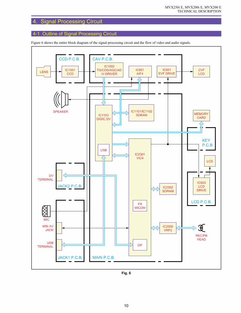
MVX250i E, MVX200i E, MVX200 ETECHNICAL DESCRIPTION
10
4. Signal Processing Circuit
4-1 Outline of Signal Processing Circuit
Figure 6 shows the entire block diagram of the signal processing circuit and the flow of video and audio signals.
Fig. 6
LENS
CCD P.C.B.
KEYP.C.B.
JACK2 P.C.B.
JACK1 P.C.B. MAIN P.C.B.
LCD P.C.B.
CAV P.C.B.
MEMORYCARD
IC1103DIGIC DV
IC801AIF4
LCD
CVFLCD
IC1001CCD
IC2302SDRAM
IC903LCD
DRIVE
IC501EVF DRIVE
IC2000VRP2
IC1101/IC1102SDRAM
IC2301VIC4
IC1002TG/CDS/AGC/AD
/V-DRIVER
USB
DIF
FRMICOM
MIN AVJACK
USBTERMINAL
DVTERMINAL
MIC
SPEAKER
REC/PBHEAD

MVX250i E, MVX200i E, MVX200 ETECHNICAL DESCRIPTION
11
4-2 Camera/Card Signal Processing
4-2-1 Camera Motion Picture Recording
4-2-2 Card Still Picture Recording
Fig. 7
JPEGJPEG
Audio
SynthesisCOMP
Deformation, DrawingREND
Camera signal processing
GRABCARD IF
proc resize nr VIC4IC2301
FRMI-COM
SDRAM IF
AIFIC801
IC1103DIGIC DV
CDS/AGC/AD/TG/
V-DRIVERIC1002
CCDIC1070
36MHz 12bit36MHz
64 Mbit SDRAMIC1102
32 bit
64 Mbit SDRAMIC1101
32 bit
Fig. 8
JPEG
Audio
SDRAM IF
CARD IF
proc resize nr
VIC4IC2301
SDCARD
DMAFR
MI-COM
RAW YCC 1 YCC 2
AIFIC801
USB
Camera signal processing
GRAB
SynthesisCOMP
Deformation, DrawingREND
IC1103DIGIC DV
64 Mbit SDRAMIC1102
32 bit
64 Mbit SDRAMIC1101
32 bit
CDS/AGC/AD/TG/
V-DRIVERIC1002
CCDIC1070
36MHz 12bit36MHz

MVX250i E, MVX200i E, MVX200 ETECHNICAL DESCRIPTION
12
4-2-3 Card Motion Picture Recording
<CCD> IC1001
• 1/4.5 inches interlaced CCD
• Complementary color filter
• Total number of pixels Approx. 1,330,000
Effective number of pixels Tape : Approx. 860,000 / Card : Approx. 1,230,000
<CDS/AGC/AD/TG/V-DRIVER> IC1002
A signal read out of the CCD is extracted. Then, after the extracted signal is subjected to AGC processing and A/D conversion, it
is output as a digital signal.
<DIGIC DV> IC1103
This circuit carries out various camera signal processing operations (EIS, AWB, etc.), and digital effect processing. It also performs
multimedia-application signal processing mainly for still image recording.
• Feature engine
• High-speed card interface
• JPEG
• Audio data compression (ADPCM)
• USB function
<SDRAM> IC1102, IC1101
Field memory for camera signal processing and digital effect processing
Image data memory for Memory card write/read operation
Fig. 9
JPEG
Audio
CARD IF
proc nr
SDCARD
DMA
YCC 1 YCC 2
AIFIC801
resize
SDRAM IF
Camera signal processing
GRAB
SynthesisCOMP
Deformation, DrawingREND
VIC4IC2301
FRMI-COM
IC1103DIGIC DV
64 Mbit SDRAMIC1102
32 bit
64 Mbit SDRAMIC1101
32 bit
CDS/AGC/AD/TG/
V-DRIVERIC1002
CCDIC1001
36MHz 12bit36MHz

MVX250i E, MVX200i E, MVX200 ETECHNICAL DESCRIPTION
13
4-3 Recorder Signal Processing
< VIC4 >IC2301
• The VIC, MI-COM, DIF INTERFACE and VIDEO INTERFACE circuits are integrated on a single semiconductor chip.
• A/B DATA : Input in camera mode. B DATA is output and A DATA is input at playback. (DIGIC DV digital effect circuit is
used at playback.)
The video data and signals input to VIC4 are subjected to digital VCR format signal processing. Audio data,
subcode data and ITI data are also created at VIC4, and these signals are output to VRP2 as 41.85 Mbps data of
DV format.
• DIF : After conversion to digital data conforming to IEEE1394 standard, the data is output at DV terminal. At digital
input, the data enters VIC4 signal processing circuit via the opposite route.
< VRP2 >IC2000
Recording data of 41.85 Mbps output from VIC4 is amplified at VRP2, and is recorded on magnetic tape while undergoing head
switching of CH-1, CH-2 with a switching pulse. At playback, the head output signal is amplified and sent to VIC4.
Fig. 10
AV JACKS TERMINAL
CVFLCD
LCD
IC1103DIGIC
DV
VIDEOINTERFACE
A DATA
B DATA
R,G,B
D/A75ΩDRIVE
A/D
IC2302SDRAM
REC/PBPROCESS
ECCCOMPRESSION/DEMOD.
BUS
IC2301VIC4
VIC BLOCK DIF BLOCK
MI-COM. BLOCK
SDRAMINTERFACE
DIFINTERFACE
FR MI-COM.Cache
1K ByteCO-
processer
AUDIO INTERFACE
IC2000VRP2
DV TERMINAL
AVJACK
IC801AIF4
VIDEOHEAD
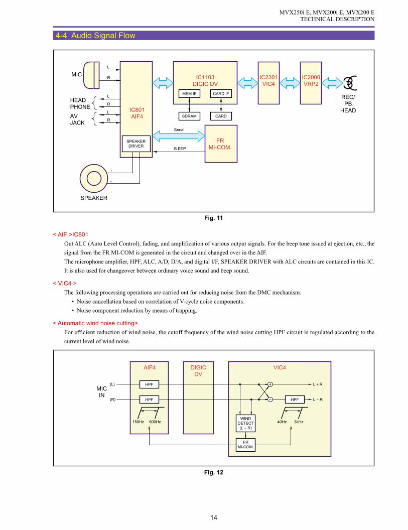
MVX250i E, MVX200i E, MVX200 ETECHNICAL DESCRIPTION
14
4-4 Audio Signal Flow
< AIF >IC801
Out ALC (Auto Level Control), fading, and amplification of various output signals. For the beep tone issued at ejection, etc., the
signal from the FR MI-COM is generated in the circuit and changed over in the AIF.
The microphone amplifier, HPF, ALC, A/D, D/A, and digital I/F, SPEAKER DRIVER with ALC circuits are contained in this IC.
It is also used for changeover between ordinary voice sound and beep sound.
< VIC4 >
The following processing operations are carried out for reducing noise from the DMC mechanism.
• Noise cancellation based on correlation of V-cycle noise components.
• Noise component reduction by means of trapping.
< Automatic wind noise cutting>
For efficient reduction of wind noise, the cutoff frequency of the wind noise cutting HPF circuit is regulated according to the
current level of wind noise.
Fig. 11
SPEAKERDRIVER
FRMI-COM.
IC801AIF4
IC1103DIGIC DV
IC2301VIC4
IC2000VRP2
+
−
L
L
R
L
R
RMIC
HEADPHONE
AVJACK
B EEP
Serial
SPEAKER
MEM IF CARD IF
SDRAM CARD
REC/PB
HEAD
Fig. 12
AIF4 VIC4DIGICDV
(L)
(R)
L + R
L − R
MICIN
HPF
HPF HPF
WINDDETECT(L − R)
FRMI-COM.
150Hz 600Hz 40Hz 3kHz

MVX250i E, MVX200i E, MVX200 ETECHNICAL DESCRIPTION
15
5. System Control, Servo
5-1 Outline of System Control, Servo
Figure 13 shows the overall configuration of the system control & servo circuit, plus the flow of data. System control is performed
by the FR MI-COM (IC2301) and MODE MI-COM (IC100) on MAIN P.C.B.
Fig. 13
DMC III
MAIN P.C.B.
LCD P.C.B.
JACK1 P.C.B.
JACK2 P.C.B.
OPERATIONKEY UNIT
ZOOMPHOTO UNIT
CAV P.C.B. KEY P.C.B.
HEAD
REMOTE CONTROLSIGNAL RECEIVER
M
FG/PG
DRUM
CAPSTAN
LOADING
FG
M
M
IC901EEPROM
ZOOM SW
START/STOPSW
PHOTO SW
SELECT SW
R-KEY
EJECT SW
POWER SW
IC903LCD
DRIVER
IC3201DC/DC
CONVERTER
FRMI-COM
IC1103DIGIC
DV
VIC
IC100MODE
MI-COM
IC801AIF4
IC1501EVF
DRIVER
IC1200LENS
DRIVER
IC2000VRP2
IC2300FLASH
MEMORYCARD
IC1002CDSAGC
A/D TGV-DRIVER
LENS
IC301MOTORDRIVER
IC2301VIC4
CAPSTAN
DRIVER
DRUM
DRIVER
MODE SWC.DOWN SW
BOT/EOTSENS.DEW
REEL FG
MIC
LOADING
DRIVER
D-VS
D-VM
C-VM
C-ERR
D-ERR
C-VS
DFG/PG
CFG
IRISDRIVE
MOTORDRIVE

MVX250i E, MVX200i E, MVX200 ETECHNICAL DESCRIPTION
16
5-2 Major Functions of Each MI-COM
(1) FR MI-COM (IC2301 : VIC4)
The FR MI-COM, as the nucleus of the system, carries out control of mode transition plus mechanism control through communi-
cation with MODE MI-COM. It also detects of various sensors and switches (DMCIII). Following are the major functions.
• VIC (Video) control / AIF4 (Audio Interface) controls
• Control in accordance with IEEE1394
• USB interface control
• AUDIO control
• DMC III mechanism control
• DIGIC DV control
• Card control
• CCD drive control
• AE, AF, AWB control
• EIS (Electric Image Stabilizer) control
• OSD (On Screen Display) bitmap control
• PRINTER control
* The FR MI-COM in this machine does not have a dedicated EEPROM. Since a flash ROM is used for the FR
MI-COM as a substitute for the EEPROM, it is required to update the flash ROM after adjustment and data
modification regarding the FR MI-COM.
(2) MODE MI-COM (IC100)
The MODE MI-COM is mainly in charge of the power-on sequence and charging control. Following are the major functions.
• Key input
• LCD / EVF control
• Remote control input
• Power ON/OFF control
• Built-in charge circuit control
• MIC (Memory In Cassette) control
* The MODE MI-COM in this machine does not have a dedicated EEPROM. Since a flash ROM is used for the
FR MI-COM as a substitute for the EEPROM, it is required to update the flash ROM after adjustment and data
modification regarding the FR MI-COM.
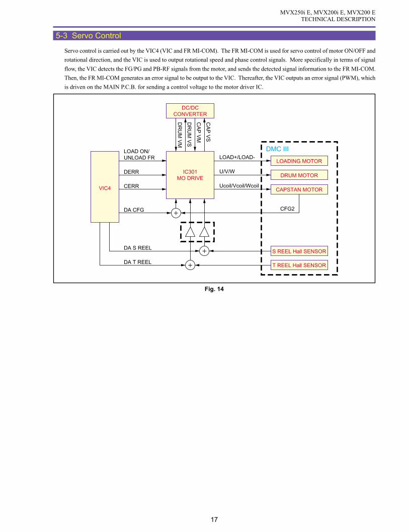
MVX250i E, MVX200i E, MVX200 ETECHNICAL DESCRIPTION
17
5-3 Servo Control
Servo control is carried out by the VIC4 (VIC and FR MI-COM). The FR MI-COM is used for servo control of motor ON/OFF and
rotational direction, and the VIC is used to output rotational speed and phase control signals. More specifically in terms of signal
flow, the VIC detects the FG/PG and PB-RF signals from the motor, and sends the detected signal information to the FR MI-COM.
Then, the FR MI-COM generates an error signal to be output to the VIC. Thereafter, the VIC outputs an error signal (PWM), which
is driven on the MAIN P.C.B. for sending a control voltage to the motor driver IC.
Fig. 14
VIC4
S REEL Hall SENSOR
LOADING MOTOR
DRUM MOTOR
CAPSTAN MOTOR
T REEL Hall SENSOR
LOAD ON/UNLOAD FR
DERR
LOAD+/LOAD-DMC III
U/V/W
Ucoil/Vcoil/Wcoil
CFG2C
AP
VS
CA
P V
M
DR
UM
VS
DR
UM
VM
CERR
DA CFG
DA S REEL
DA T REEL
IC301MO DRIVE
DC/DCCONVERTER
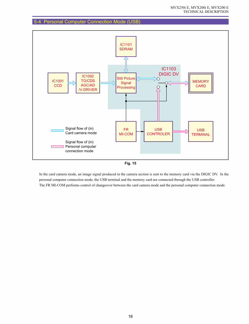
MVX250i E, MVX200i E, MVX200 ETECHNICAL DESCRIPTION
18
5-4 Personal Computer Connection Mode (USB)
In the card camera mode, an image signal produced in the camera section is sent to the memory card via the DIGIC DV. In the
personal computer connection mode, the USB terminal and the memory card are connected through the USB controller.
The FR MI-COM performs control of changeover between the card camera mode and the personal computer connection mode.
Fig. 15
Signal flow of (in)Card camera mode
Signal flow of (in)Personal computer connection mode
IC1101SDRAM
IC1103DIGIC DV
MEMORYCARD
USBTERMINAL
Still PictureSignal
Processing
FRMI-COM
USBCONTROLER
IC1001CCD
IC1002TG/CDSAGC/AD
/V-DRIVER

MVX250i E, MVX200i E, MVX200 ETECHNICAL DESCRIPTION
19
5-5 Error Detection
If an abnormality has been occurred in any rotation drive system (drum, capstan, reel, loading), a relevant mode enters. The LCD
indicates “PLEASE UNLOAD THE CASSETTE” and blinks “EJECT”.
5-5-1 Error Detecting Conditions
The following table gives error detecting conditions.
5-5-2 Processing after Error Detection
The following table gives processing after error detection.
• Pop up : Error display→error eject → pop up →error clear
• Error stop : Error display→STOP position (not cleared unless EJECTED)
Kind Condition Detection
Drum error Error detecting mode Starting / steady D-FG
FG frequency when steady 900Hz
Error detecting level Starting: Beyond 80-150%.
Steady : 30% max.
Error detecting time Starting : 5sec.
Steady : 0.5sec.
Capstan error Error detecting mode Starting / steady C-FG
FG frequency when steady 1347Hz
Error detecting level Starting : 80% max.
Steady : 60Hz max.
Error detecting time Starting : 2sec.
Steady : 2sec.
Reel error Error detecting mode Starting / Normal / UNLOAD T, S-REEL FG
Error detection Normally : The C-FG count per reel FG cycle is C-FG
Starting : More than 3296
Steady : More than 2256
UNLOAD : Reel FG cycle is 1 sec or more
(Take-up reel only for both)
Loading error Error detecting mode Mode transfer Mode SW
Error detection Mode transfer time
STANDBY-STOP : 6sec
STANDBY-POPUP : 3sec
STOP-PLAY : 3sec
Cassette in LoadingDuring
unloadingLoading
completedDuring tape
runningDuring mode
transfer
Drum error Pop up Pop up Error stop Error stop Error stop Error stop
Capstan error Pop up ------- Error stop Error stop Error stop Error stop
Reel error ------- ------- Error stop Error stop Error stop Error stop
Loading error Pop up Pop up Error stop Error stop ------- Error stop

DISASSEMBLING
CONTENTS
1. Disassembling and Reassembling
Notes
List of Supplies
1-1 Disassembling / Reassembling Flowchart -------------------------------------------------------------------------------------------- 3
1-2 Separation of Accessory Shoe and LI Battery Holder ------------------------------------------------------------------------------- 4
1-3 Separation of Top Cover Ass’y --------------------------------------------------------------------------------------------------------- 5
1-4 Separation of R-LCD Unit -------------------------------------------------------------------------------------------------------------- 6
1-5 Separation of Rear Cover Unit --------------------------------------------------------------------------------------------------------- 7
1-6 Separation of Front Cover Unit -------------------------------------------------------------------------------------------------------- 8
1-7 Separation of Left Cover Unit ---------------------------------------------------------------------------------------------------------- 9
1-8 Separation of Shields ------------------------------------------------------------------------------------------------------------------ 10
1-9 Separation of CVF Unit --------------------------------------------------------------------------------------------------------------- 12
1-10 Separation of JACK 2 P.C.B. ------------------------------------------------------------------------------------------------------- 13
1-11 Separation of Camera Unit ---------------------------------------------------------------------------------------------------------- 14
1-12 Separation of CAV P.C.B. ----------------------------------------------------------------------------------------------------------- 15
1-13 Separation of MAIN P.C.B. --------------------------------------------------------------------------------------------------------- 16
1-14 Separation of Recorder Holder ----------------------------------------------------------------------------------------------------- 18
1-15 Disassembly of Front Cover Unit - 1 ---------------------------------------------------------------------------------------------- 19
1-16 Disassembly of Front Cover Unit - 2 ---------------------------------------------------------------------------------------------- 21
1-17 Disassembly of Front Cover Unit - 3 ---------------------------------------------------------------------------------------------- 23
1-18 Disassembly of Left Cover Unit - 1 ------------------------------------------------------------------------------------------------ 24
1-19 Disassembly of Left Cover Unit - 2 ------------------------------------------------------------------------------------------------ 26
1-20 Disassembly of Left Cover Unit - 3 ------------------------------------------------------------------------------------------------ 28
1-21 Disassembly of R-LCD Unit - 1 ---------------------------------------------------------------------------------------------------- 30
1-22 Disassembly of R-LCD Unit - 2 ---------------------------------------------------------------------------------------------------- 31
1-23 Disassembly of R-LCD Unit - 3 ---------------------------------------------------------------------------------------------------- 32
1-24 Disassembly of Right Cover Unit -------------------------------------------------------------------------------------------------- 33
1-25 Disassembly of LCD Unit - 1 ------------------------------------------------------------------------------------------------------- 34
1-26 Disassembly of LCD Unit - 2 ------------------------------------------------------------------------------------------------------- 35
1-27 Disassembly of LCD Hinge Unit --------------------------------------------------------------------------------------------------- 37
1-28 Disassembly of Rear Cover Unit - 1 ----------------------------------------------------------------------------------------------- 38
1-29 Disassembly of Rear Cover Unit - 2 ----------------------------------------------------------------------------------------------- 39
1-30 Disassembly of CVF Unit - 1 ------------------------------------------------------------------------------------------------------- 40
1-31 Disassembly of CVF Unit - 2 ------------------------------------------------------------------------------------------------------- 41
1-32 Disassembly of CVF Unit - 3 ------------------------------------------------------------------------------------------------------- 43
1-33 Disassembly of CVF Unit - 4 ------------------------------------------------------------------------------------------------------- 44
1-34 Disassembly of CVF Unit - 5 ------------------------------------------------------------------------------------------------------- 45
1-35 Disassembly of Camera Unit -------------------------------------------------------------------------------------------------------- 46
1-36 Disassembly of Lens Unit ----------------------------------------------------------------------------------------------------------- 47
1-37 List of Screws Used ------------------------------------------------------------------------------------------------------------------ 48
1-38 List of Disassembly Photos ---------------------------------------------------------------------------------------------------------- 49

MVX250i E, MVX200i E, MVX200 EDISASSEMBLING
1
1. Disassembling and Reassembling - (1)
Notes
(1) When replacing the flat cable with a new one, allow it to remain folded the same as the original part.
(2) The flat cable has a contact orientation to be engaged with the connector. Refer to the instructions in the disassembly procedure
diagram and interconnection diagram for boards.
(3) To secure screws, apply the Three Bond 1401B (CY9-8011-000)
(4) If any part to be replaced has UL tape attached on it, be sure to reattach UL tape at the same position in reassembling.
(5) Use the new type connector (MAIN P.C.B. CN102) as illustrated.
FPCFPC
Lock Unlock
Metalcontact
Metalcontact
(6) For replacing the fuse mounted on the MAIN P.C.B., it is required to remove the CVF unit.
• Lateral engaging connector
(The instructions are given in the disassembly proce-
dure diagram and board interconnection diagram.)
: Contacts are positioned downward. (board side)
∗ : Contacts are positioned upward.
Metal contact (Pins' face up)
Metal contact (Pins' face down)
:
:
• Lengthwise engaging connector
( The instructions are given in the disassembly proce-
dure diagram and board interconnection diagram.)
Indicated by → Arrowheads indicate the contacts, and the
shafts indicate the noncontacts.
Metal contact
Metal contact

MVX250i E, MVX200i E, MVX200 EDISASSEMBLING
2
1. Disassembling and Reassembling - (2)
List of Supplies
Item Name Item Number Purpose Remarks
Grease FLOIL C-1Z DY9-3039-000 Lubrication DMC III
Grease FLOIL 948P DY9-3051-000 Lubrication DMC III
Hanal FL-778 DY9-3026-010 Lubrication Cover
Hanal KS-39M DY9-3053-000 Lubrication Cover
Hanal KS-50M DY9-3047-000 Lubrication Cover, DMC III
EM-30L DY9-3031-000 Lubrication Cover
Dia Bond No. 1663G CY9-8129-000 Adhesive LCD
Sponge (W H × T : 300mm 200mm 6mm) DY9-4001-000 General-purpose vibration isolating
/sound absorbing material
Adhesive Tape, No.354E DY9-3032-000 General-purpose adhesive tape
(W L × T : 9mm × 50m × 0.15mm, UL type)
Adhesive Tape, No. 501F DY9-3034-000 General-purpose
(W × L × T : 10mm × 50m × 0.16mm, UL type) double-side-coated adhesive tape
Sheet, Shield (W × H : 250mm × 250mm) DY9-3036-000 General-purpose shield material

MVX250i E, MVX200i E, MVX200 EDISASSEMBLING
3
1-1 Disassembling / Reassembling Flowchart
(1) Find the replacement part on the chart, and disassemble it following the instruction on chart.
(2) Reassembling can be made by reversing the disassembling procedures.
START : MAIN FLOW
: SUB FLOW
: MAIN UNIT
1-22 KEY P.C.B.
1-29 Power Switch Ass'y
1-29 Rear Cover
1-4 R-LCD Unit
1-6 Front Cover Unit
1-7 Left Cover Unit
1-15 Jack1 P.C.B.
1-17 Front Cover Ass'y
1-16 Mic Ass'y
1-18 Zoom Photo Key Ass'y
1-19 Speaker
1-10 Jack2 P.C.B.
1-20 Cassette Arm Ass'y
1-5 Rear Cover Unit
1-8 Camera Recorder CVF Unit
1-23 LCD Unit
1-11 Recorder Unit
1-9 CVF Unit
1-11 Camera Unit
1-23 Right Cover Unit
1-25 LCD Hinge Unit
1-24 Right Cover Ass'y
1-26 Backlight Ass'y
1-26 LCD P.C.B.
1-26 LCD Ass'y
1-35 CCD Ass'y
1-35 Lens Ass'y
1-35 CCD P.C.B.
1-12 CAV P.C.B.
1-13 Main P.C.B.
1-14 DMC lll
1-33 CVF Ass'y
1-33 CVF P.C.B.
END
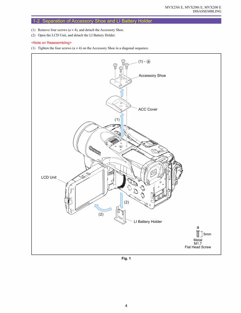
MVX250i E, MVX200i E, MVX200 EDISASSEMBLING
4
1-2 Separation of Accessory Shoe and LI Battery Holder
(1) Remove four screws (a × 4), and detach the Accessory Shoe.
(2) Open the LCD Unit, and detach the LI Battery Holder.
<Note on Reassembling>
(1) Tighten the four screws (a × 4) on the Accessory Shoe in a diagonal sequence.
Fig. 1
5mm
a
MetalM1.7
Flat Head Screw
Accessory Shoe
ACC Cover
LCD Unit
LI Battery Holder
(1)
(2)
(2)
(1) - a

MVX250i E, MVX200i E, MVX200 EDISASSEMBLING
5
1-3 Separation of Top Cover Ass’y
(1) Open the Cassette Cover, and remove one screw (b × 1).
(2) Disengage claws A and B. While being free from part E of the Shoe Connector, pull up the claw A and claw B sides to demount the
Top Cover Ass’y.
<Note on Reassembling>
(1) When remounting the Top Cover Ass’y, engage claws B and C first. Then, while being free from the part E of the Shoe Connector,
insert the claw A and part D sides for engagement.
Fig. 2
5mm
MetalM1.7
b
Top Cover Ass'y
Cassette Cover
Claw A
Part D
Part E
Claw B
Claw C
(1) - b
(2)
(1)

MVX250i E, MVX200i E, MVX200 EDISASSEMBLING
6
1-4 Separation of R-LCD Unit
(1) Remove eleven screws (c × 1, d × 5, e × 2, f × 2, g × 1), disconnect the CN101, and detach the R-LCD Unit.
Fig. 3
3mmMetalM1.7
ge fd4mm
MetalM1.7
(self tap)
5mm
MetalM1.7
(self tap)
4mm
MetalM1.7
6mm
MetalM1.7
c
R-LCD Unit
(1) - cCN101(1)
(1)
(1) - e
(1) - d
(1) - d
(1) - d
(1) - d
(1) - d
(1) - e
(1) - f
(1) - f
(1) - f
(1) - f(1) - g

MVX250i E, MVX200i E, MVX200 EDISASSEMBLING
7
1-5 Separation of Rear Cover Unit
(1) Disengage the Grip Belt from the Grip Hook.
(2) Open the Cassette Cover, and remove four screws (d × 1, h × 3).
(3) Disconnect the CN101 and CN3202, and detach the Rear Cover Unit.
Fig. 4
3mmMetalM1.7
d3.5mm
MetalM1.7
h
Cassette Cover
Rear Cover Unit
Grip Belt
Grip Hook
CN101
CN3202 (3)
(3)
(3)
(1)
(2)
(2) - d
(2) - h
(2) - h
(2) - h

MVX250i E, MVX200i E, MVX200 EDISASSEMBLING
8
1-6 Separation of Front Cover Unit
(1) Open the Jack1 Cover and Jack2 Cover, and remove six screws (h × 4, i × 1, j × 1).
(2) Disconnect the CN3211, CN42, and CN51. Then, while being free from the Lens Shield, detach the Front Cover Unit.
(Refer to 1-8 : Separation of Shields.)
Fig. 5
3.5mmMetalM1.7
h
5.5mm
MetalM1.7
i
MetalM1.7
2mm
j
Jack1 Cover
Jack2 Cover
(2)
(2)
(2) (2)
(1)
(1)
CN51
CN3211
CN42
(1) - h
(1) - h
Lens Shield
(1) - h
(1) - h
(1) - h
(1) - i
(1) - i
(1) - j

MVX250i E, MVX200i E, MVX200 EDISASSEMBLING
9
1-7 Separation of Left Cover Unit
(1) Remove four screws (k × 4).
(2) Open the Cassette Cover, disconnect the CN100, and then detach the Left Cover Unit.
<Note on Reassembling>
(1) In reassembling the Left Cover Unit, connect the CN100 first. Then, mount the Left Cover Unit while taking sufficient care not to
damage the flexible cable.
Fig. 6
k2.5mm
MetalM1.7
(2)
(2)
Left Cover UnitCassette Cover
CN100
(2)
(1) - k
(1) - k
(1) - k
(1) - k
(1) - k
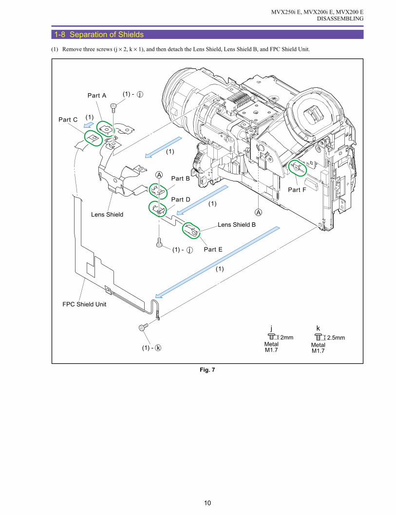
MVX250i E, MVX200i E, MVX200 EDISASSEMBLING
10
1-8 Separation of Shields
(1) Remove three screws (j × 2, k × 1), and then detach the Lens Shield, Lens Shield B, and FPC Shield Unit.
Fig. 7
k2.5mm
MetalM1.7
MetalM1.7
2mm
j
(1)
(1)
(1)
(1)
Part A
Part C
Lens Shield
Part B
Part D
Part E
Part F
FPC Shield Unit
A
A
(1) - k
(1) - j
(1) - j
Lens Shield B

MVX250i E, MVX200i E, MVX200 EDISASSEMBLING
11
<Note on Reassembling>
(1) Reassemble the Lens Shield, Lens Shield B, and FPC Shield Unit as illustrated below.
(Refer to 1-6 : Separation of Front Cover Unit.)
(2) Attach the FPC Shield above the CAV-JACK1 FPC (8 pins) to provide a distance as large as possible. With the MAIN-KEY FPC
folded, it shall not come into direct contact with the CAV-JACK1 FPC.
Fig. 8
Note on Reassembling (1)
Note on Reassembling (2)
Front Cover
Lug terminal mountingangle : Within 45.0
A Part of Lens Shield
Refer to 1-6:Separation of Front Cover Unit.
C Part of FPC Shield
B Part of Lens Shield
D Part of Lens Shield B
F Part of CVF Unit
E Part of Lens Shield B
MAIN-KEY FPCCAV-JACK1 FPC FPC Sheld Unit

MVX250i E, MVX200i E, MVX200 EDISASSEMBLING
12
1-9 Separation of CVF Unit
(1) Detach the Shoe Connector Ass’y. (MVX250i E only)
(2) Disconnect the CN891, and detach the ACS-MAIN FPC. (MVX250i E only)
(3) Remove three screws (k × 2, h × 1), and then detach the Shoe Base and GND Plate.
(4) Turn up the CVF Unit, remove one screw (h × 1), disconnect the CN1501, and demount the CVF Unit.
<Note on Reassembling>
(1) Before using a service part of GND Plate, attach the UL Tape to the position indicated in the figure below.
(2) Attach the GND plate to the Shoe Base as illustrated below.
k2.5mm
MetalM1.7
3.5mmMetalM1.7
h
Note on Reassembling (2)
Note on Reassembling (1)
(2)
(3)
(2)
(3)
(4)
(4)
CVF Unit
Shoe Base
GND Plate
ACS-MAIN FPC
CN891CN1501
MVX250i E only
(4) - h
GND PlateShoe Base
(3) - h(3) - k
MVX250i E onlyGND Plate
A surplus part of the ULTape shall be foldedonto the back side.
Attach the UL tape before reassembling.
Attachmentreference
UL Tape (9 × 25)
(1) Shoe Connector Ass'y(3) - k
Fig. 9

MVX250i E, MVX200i E, MVX200 EDISASSEMBLING
13
1-10 Separation of JACK 2 P.C.B.
(1) Detach the Cushion RC1 and RC2.
(2) Remove two screws (k × 2), disconnect the CN91, and detach the JACK2 P.C.B.
(3) Detach the CAV-JACK1 FPC and MAIN-JACK1 FPC from the CN701 and CN2101.
<Note on Reassembling>
(1) Before mounting the JACK2 P.C.B., run the MAIN-JACK1 FPC, CAV-JACK1 FPC, and MAIN-JACK1 Cable through groove A.
(2) Attach the Cushion RC1 and RC2 to the position indicated in the figure below.
Fig. 10
k2.5mm
MetalM1.7
Note on Reassembling (1),(2)
JACK2 P.C.B.
CAV-JACK1 FPC
CAV-JACK1 FPC
MAIN-JACK1 FPC
MAIN-JACK1 FPC
MAIN-JACK1 Cable
(2)(3)
(3)CN91
(2)
CN701
CN2101
Groove A
(1)
(1)
Align to thehole center.
Align to a point 1.5 mm abovethe edge of the P.C.B.
Align to the outline of the DV Connector.
(2) - k
(2) - k
Cushion RC1
Cushion RC2
Cushion RC1
Cushion RC2
1.5mm
JACK2 P.C.B.

MVX250i E, MVX200i E, MVX200 EDISASSEMBLING
14
1-11 Separation of Camera Unit
(1) Remove two screws (j × 1, l × 1), and then detach the Sub Holder and Insulation Rubber.
(2) Remove two screws (l × 2), detach the UL Tape, and disconnect the CN1000 and CN1200. Then, detach the Camera Unit, Ferrite
Core, and Insulation Rubber.
<Note on Reassembling>
(1) With the UL Tape, secure the Ferrite Core to the position indicated in the figure below so that it will not be dislocated.
<Instruction for Supply>
Entire surface of Insulation Rubber : Hanal KS-39M (DY9-3053-000)
Fig. 11
l4.5mm
MetalM1.7
Steped Screw
MetalM1.7
2mm
j
Instruction for Supply Note on Reassembling (1)
Sub Holder
Camera Unit
UL Tape (9 × 30)
UL Tape (9 × 30)
Ferrite Core
Ferrite Core
Insulation Rubber
Insulation Rubber
Insulation Rubber
Recorder Unit
(2)(2)
(2)
(2)CN1200
CN1000
Insulation Rubber
Hanal KS-39M
Attachment reference
Fold theUL tape.
Rear View
(2) - l
(2) - l
(1) - l
(1) - j

MVX250i E, MVX200i E, MVX200 EDISASSEMBLING
15
1-12 Separation of CAV P.C.B.
(1) Disconnect the CN1001 and CN1100 (B to B), and then detach the CAV P.C.B.
(2) Disconnect the CN3201, remove the UL Tape, and detach the MAIN-JACK1 Cable.
(3) Disconnect the CN102 and CN2102, and then detach the MAIN-KEY FPC and MAIN-JACK2 FPC.
Note : Use the CN102 (MAIN P.C.B.) as illustrated below.
(4) Remove the UL Tape from the MAIN-KEY FPC, and detach the Ferrite Core.
<Note on Reassembling>
(1) With the UL Tape, secure the Ferrite Core to the position indicated in the figure below so that it will not be dislocated.
(2) Attach the MAIN-JACK1 Cable as illustrated below, and then secure it with the UL Tape.
Fig. 12
Note
Note on Reassembling (1) Note on Reassembling (2)
CAV P.C.B.
MAIN - JACK1 Cable
MAIN - JACK2 FPC
MAIN - KEY FPC
MAIN-KEY FPC
UL Tape (13 × 21)
UL Tape (13 × 21)
Ferrite Core
Ferrite Core
(1)
(2)
(2)
(4)(3)
(3)
(4)
CN3201
CN1001(B to B)
CN1100(B to B)
CN2102
CN102
UL Tape (9 × 36)
Run the cable through a clearance between the ICs and the connectors so that it is not pinched between them.
FPCFPC
Locked Unlocked
CN100
CN1100
CN302
CN3201
CN3202
CN101
IC301
IC300
IC100
CN303
UL Tape(9 × 36)
ContactContact

MVX250i E, MVX200i E, MVX200 EDISASSEMBLING
16
1-13 Separation of MAIN P.C.B.
(1) Remove three screws (k × 3), UL Tape, and disconnect the CN300, CN301, CN302, and CN2000. Then, detach the MAIN P.C.B.
(2) Detach the HA Shield, Shielding Rubber, PM1 Shield and PM2 Shield, from the MAIN P.C.B.
(3) Detach the Core Cushion
Fig. 13
k2.5mm
MetalM1.7
(2)
(2)
(2)(2)
(3)(1)
(1)
PM2 Shield
HA Shield
PM1 Shield
MAIN P.C.B.
CN2000
CN303
CN302
CN300
CN301
A
B
AB
CoreCushion
(1) - k
(1) - k
(1) - k ShieldingRubber
UL Tape (9 × 20)

MVX250i E, MVX200i E, MVX200 EDISASSEMBLING
17
<Note on Reassembling>
(1) Attach the Core Cushion to the position indicated in the figure below.
(2) Attach the Shielding Rubber to the PM Shield as illustrated below.
(3) Secure the flexible cable by attaching the UL Tape to the position indicated in the figure below.
Fig. 14
Note on Reassembling (1)
Note on Reassembling (2)
Note on Reassembling (3)
RecorderHolder
Shielding RubberPM1 Shield
PM1 Shield
PM2 Shield
Shielding Rubber
PM Shield
MAIN P.C.B.
MAIN P.C.B.
The UL tape shall not protrude fromthe outline of the Motor.
It is not allowed to attachthe Shielding Rubber inan overlaying form.
Take care not to let the Shielding Rubberbe sandwiched between the MAIN P.C.B.and the MAIN Holder.
When attaching the Shielding Rubber, push itto the part A of the Recorder Holder so thatthe MAIN P.C.B. will not be unseated.
UL Tape (9 × 20)
Motor
Core Cushion
MAIN P.C.B.
MAIN P.C.B.
Part A
Top endof IC
End of P.C.B.
Attachment reference
Attachment reference

MVX250i E, MVX200i E, MVX200 EDISASSEMBLING
18
1-14 Separation of Recorder Holder
(1) Remove three screws (m × 3), and detach the Spring, Recorder Holder, and Insulation Rubber.
<Instruction for Supply>
Entire surface of Insulation Rubber : Hanal KS-39M (DY9-3053-000)
Fig. 15
3.4mm
MetalM1.4
Steped Screw
m
Instruction for Supply
Hanal KS-39M
Insulation Rubber
DMC III
(1)
Recorder Holder
Insulation Rubber
Insulation Rubber
Insulation Rubber
Spring(1) - m
(1) - m
(1) - m

MVX250i E, MVX200i E, MVX200 EDISASSEMBLING
19
1-15 Disassembly of Front Cover Unit - 1
(1) Detach the Jack2 Cover.
(2) Disconnect the CN43, and remove three screws (e × 1, f × 1, h × 1). Then, detach the Cushion, GND Plate, LED Window, and
JACK1 P.C.B.
(3) Slide the Jack2 Panel in the arrow direction to disengage the dowel A, and detach the Jack2 Panel.
e f4mm
MetalM1.7
(self tap)
5mm
MetalM1.7
(self tap)
3.5mmMetalM1.7
h
Jack2 Cover
Jack2 Panel
(3)
Dowel A
JACK1 P.C.B.
LED Window
GND Plate
Cushion
(2)
(2)
(1) CN43
(2) - h
(2)
(2) - e
(2) - f
Fig. 16

MVX250i E, MVX200i E, MVX200 EDISASSEMBLING
20
<Note on Reassembling>
(1) Slide the Jack2 Panel in the arrow direction to engage the dowel A with the claw B so that the Jack2 Plate is attached to the Jack2
Cover securely.
(2) Attach the GND Plate and LED Window as illustrated below.
(3) Attach the Cushion as illustrated below.
Note on Reassembling (2)
Note on Reassembling (1) Note on Reassembling (3)
Insert part C of theGND Plate underthe LED Window.
Part C
Dowel A
Claw B
1. Insert the top end part A of the Cushion in the arrow direction, and pull it outward as shown in the figure.
Peel-off sheet side
AA LED Window
LED Window
Cylinder
Cushion
Cushion
Cushion
Cushion
E
C
C
DD
F
2. Insert the part B of the Cushion into a gap between the LED Window Cylinder and the CN51, and remove the peel-off sheet from the Cushion.
CN51
B
B
B
B
LED Window
3. Align the end of the cutout part of the F Side Cover with the edge part C of the Cushion, align the end face D with the wall face of the F Side Cover, and attach the Cushion by turning the part B.
4. Attach the Cushion by folding the parts E and F.
E
LED Window
F
GND Plate
Jack2 Panel
Jack2 Cover
LED Window
Fig. 17
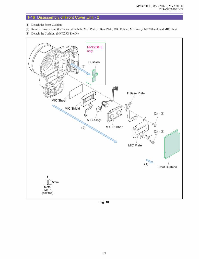
MVX250i E, MVX200i E, MVX200 EDISASSEMBLING
21
1-16 Disassembly of Front Cover Unit - 2
(1) Detach the Front Cushion
(2) Remove three screws (f × 3), and detach the MIC Plate, F Base Plate, MIC Rubber, MIC Ass’y, MIC Shield, and MIC Sheet.
(3) Detach the Cushion. (MVX250i E only)
Fig. 18
f5mm
MetalM1.7
(self tap)
F Base Plate
MIC Plate
MIC Rubber
MIC Ass'y
MIC Shield
MIC Sheet
(2)
(1)
(2) - f
(2) - f
Front Cushion
Cushion(3)
MVX250i Eonly

MVX250i E, MVX200i E, MVX200 EDISASSEMBLING
22
<Note on Reassembling>
(1) Attach the Cushion to the position indicated in the figure below. (MVX250i E only)
(2) Carry out wiring for the MIC Ass’y Cable as illustrated below.
(3) Attach the Front Cushion to the position indicated in the figure below.
Fig. 19
Note on Reassembling (1)
Note on Reassembling (2)
Note on Reassembling (3)
Cushion
Align the LED window with the dentpart of the Cushion. (Attach the Cushion so that it will notprotrude onto the LED window.)
Arrange the four cable wires in parallel so that they are not crossed over each other.
Red / Black White / Black
Arrange the four cablewires in parallel, andrun them betweenthe dowels.
L sideWhite / Black
R sideRed / Black
MVX250i Eonly
Attachmentreferencefor FrontCushion
Align the slit and the rib.
The top part of the F Cover shall be turned ontothe cylindrical wall.

MVX250i E, MVX200i E, MVX200 EDISASSEMBLING
23
1-17 Disassembly of Front Cover Unit - 3
(1) Remove three screws (f × 3), and detach the Lens Ring Ass’y, MEGA PIXEL Plate, and Lens Rubber.
(2) Using tweezers or the like, push the claw A to remove the Jack1 Cover.
(3) Detach the Front Panel.
Note : When detaching the Front Panel, push part B from the back side.
<Note on Reassembling>
(1) When attaching the Front Panel, engage the claws C, D, E, F in that order.
(2) Attach the MEGA PIXEL Plate to the Lens Ring Ass’y, and insert the Lens Rubber in the orientation indicated in the figure below
for attachment to the Front Cover Ass’y.
f
5mm
MetalM1.7
(self tap)
Note
Note on Reassembling (1)
Note on Reassembling (2)
Jack1 CoverJack1 Cover
Front Panel
Lens Ring Ass'y
Lens Ring Ass'y
Front Cover Ass'y
Lens Rubber
Lens Rubber
MEGA PIXEL Plate
MEGA PIXEL Plate
Front Cover Ass'y
(2)
(3)
Claw A
Claw A
Part B
Push
Push
(1)
(1)
(1)
Claw D
Claw F
Claw E
Claw C
(1) - f
(1) - f
Fig. 20

MVX250i E, MVX200i E, MVX200 EDISASSEMBLING
24
1-18 Disassembly of Left Cover Unit - 1
(1) Remove five screws (d × 4, t × 1).
(2) Disengage two claws A and two dowels B of the Zoom Photo Key Ass’y. Then, with the Zoom Photo Key Ass’y unseated, detach
the Open Knob.
(3) Slide the claws C and D and the dowels E and F downward, remove the Double Sided Tape from the SPEAKER FPC, and detach
the Cassette Cover.
(4) Disconnect the connector from the SPEAKER FPC Unit, and detach the Zoom Photo Key Ass’y.
(5) Detach the Zoom Top Cover and the Zoom Top Cover Tape1, 2.
Fig. 21
3mmMetalM1.7
d
BlackM1.7
(self tap)
4.5mm
t
Double Sided Tape
Dowel E Dowel F
Dowel B
Claw C
Claw A
Claw D
Connector
Connector
SPEAKER FPC
Zoom Top Cover
Zoom Photo Key Ass'y
Zoom Top Cover Tape 1
Zoom Top Cover Tape 2
Open Knob
Cassette Cover
(5)
(5)
(2)
(4)
(3) (4)
(1) - d(1) - d
(1) - d
(1) - t
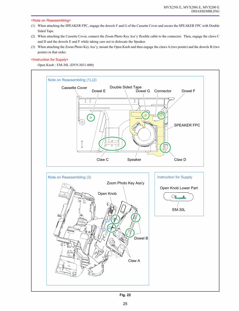
MVX250i E, MVX200i E, MVX200 EDISASSEMBLING
25
<Note on Reassembling>
(1) When attaching the SPEAKER FPC, engage the dowels F and G of the Cassette Cover and secure the SPEAKER FPC with Double
Sided Tape.
(2) When attaching the Cassette Cover, connect the Zoom Photo Key Ass’y flexible cable to the connector. Then, engage the claws C
and D and the dowels E and F while taking care not to dislocate the Speaker.
(3) When attaching the Zoom Photo Key Ass’y, mount the Open Knob and then engage the claws A (two points) and the dowels B (two
points) in that order.
<Instruction for Supply>
Open Knob : EM-30L (DY9-3031-000)
Note on Reassembling (1),(2)
Note on Reassembling (3) Instruction for Supply
Cassette CoverDowel E Dowel G Dowel F
Claw C Claw D
SPEAKER FPC
Speaker
Double Sided Tape
Zoom Photo Key Ass'y
Dowel B
Open Knob
EM-30L
Claw A
Open Knob Lower Part
Connector
Fig. 22
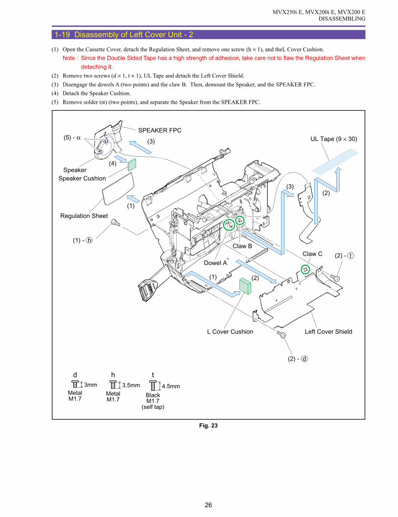
MVX250i E, MVX200i E, MVX200 EDISASSEMBLING
26
1-19 Disassembly of Left Cover Unit - 2
(1) Open the Cassette Cover, detach the Regulation Sheet, and remove one screw (h × 1), and theL Cover Cushion.
Note : Since the Double Sided Tape has a high strength of adhesion, take care not to flaw the Regulation Sheet when
detaching it.
(2) Remove two screws (d × 1, t × 1), UL Tape and detach the Left Cover Shield.
(3) Disengage the dowels A (two points) and the claw B. Then, demount the Speaker, and the SPEAKER FPC.
(4) Detach the Speaker Cushion.
(5) Remove solder (α) (two points), and separate the Speaker from the SPEAKER FPC.
3mmMetalM1.7
d3.5mm
MetalM1.7
h
BlackM1.7
(self tap)
4.5mm
t
L Cover Cushion
Dowel A
Claw B
(5) - αSPEAKER FPC
Speaker CushionSpeaker
(4)
(3)
(3)
(1)
Regulation Sheet
Left Cover Shield
(2) - d
(1) - h
(2)
(2)
(1)
Claw C
UL Tape (9 × 30)
(2) - t
Fig. 23

MVX250i E, MVX200i E, MVX200 EDISASSEMBLING
27
<Note on Reassembling>
(1) Attach the Speaker Cushion to the position indicated in the figure below.
(2) Attach the SPEAKER FPC to the position indicated in the figure below, and secure it with the claw C of the Left Cover Shield.
(3) Attach the L Cover Cushion as illustrated below.
(4) Attach the UL Tape as illustrated below.
Note on Reassembling (4)
Note on Reassembling (3)Note on Reassembling (1) Note on Reassembling (2)
Left Cover
L Cover Cushion
Attachment reference
Attach the Speaker Cushionalong the outline of the metallicpart of the Speaker.Allowable deviation inattachment : ±0.5mm Dowel A Claw B
When attaching the SPEAKERFPC, engage the dowels A andclaw B.
Speaker Cushion
Speaker
Secure with the claw C.
0 ∼ 5.0mm0 ∼ 5.0mm
The root of the flexible cableshall be attached to meetthe internal radius of the cover.
After attaching the UL tape,make sure that the FPC isnot kinky. (To prevent deviation of theoutward position of the FPC)
In the range D, the dimensions indicatedin the figure shall be satisfied.
D
UL Tape (9 × 30)
Fig. 24
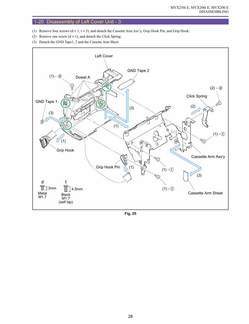
MVX250i E, MVX200i E, MVX200 EDISASSEMBLING
28
1-20 Disassembly of Left Cover Unit - 3
(1) Remove four screws (d × 1, t × 3), and detach the Cassette Arm Ass’y, Grip Hook Pin, and Grip Hook.
(2) Remove one screw (d × 1), and detach the Click Spring.
(3) Detach the GND Tape1, 2 and the Cassette Arm Sheet.
3mmMetalM1.7
d
BlackM1.7
(self tap)
4.5mm
t
Left Cover
(2)
(1)
(3)(3)
(1)
(1)
(3)
Click Spring
Cassette Arm Ass'y
Cassette Arm Sheet
GND Tape 1
GND Tape 2
Grip Hook
Grip Hook Pin
Dowel A(1) - d
(2) - d
(1) - t
(1) - t
(1) - t
Fig. 25

MVX250i E, MVX200i E, MVX200 EDISASSEMBLING
29
<Note on Reassembling>
(1) Attach the GND Tape1 to the position indicated in the figure below.
(2) Attach the GND Tape2 to the position indicated in the figure below.
(3) Attach the Click Spring and the Cassette Arm Sheet as illustrated below.
(4) With the Cassette Arm Ass’y open, attach it to the dowel A of the Left Cover and then secure the screw.
<Instruction for Supply>
Click Spring, two dented spherical points : Hanal FL-778 (DY9-3026-010)
Fig. 26
Instruction for Supply
Note on Reassembling (1) Note on Reassembling (3)
Note on Reassembling (2)
Left Cover
GND Tape1
GND Tape 2
Attach the GND Tape1 so that it is secured tothe concave part of theLeft Cover.(The GND Tape1 shallnot be unseated.)
Attach according to the outlineof the Cassette Arm Ass'y.No interference with the Stoppershall occur at the time of turning. Allowable deviation ofattachment : ±0.5 mm.
Allowable deviation in attachment,unless otherwise specified : ±0.5 mm.
Align the cutout part with the steppedpart of the left cover.(Protrusion is not allowed.)
Align with the end face of the left cover.(Protrusion is not allowed.)
Click Spring
CassetteArm Ass'y
CassetteArm Sheet
Stopper
Click Spring
Hanal FL-778
Fold the hatched part to the back side.(Fold through an angle 180 according to the shape of the cutout.)

MVX250i E, MVX200i E, MVX200 EDISASSEMBLING
30
1-21 Disassembly of R-LCD Unit - 1
(1) Remove one screw (f × 1), and detach the Rubber Insulation and the Tripod Base.
(2) Remove one screw (e × 1), and detach the Hold Label and the GND Plate.
(3) Remove one screw (f × 1), disengage the claws A and B, and detach the LI Case.
<Notes on Reassembling>
(1) Attach the Hold Label to the position indicated in the figure below.
Fig. 27
e f4mm
MetalM1.7
(self tap)
5mm
MetalM1.7
(self tap)
Note on Reassembling (1)
(1)
Tripod Base(1)
(2)
(2)
(3)
Craw B
GND Plate
Craw A
LI Case
(2) - e
(3) - f
GND Plate
(1) - f
Rubber Insulation
Hold Label
Hold Label

MVX250i E, MVX200i E, MVX200 EDISASSEMBLING
31
1-22 Disassembly of R-LCD Unit - 2
(1) While being free from the GND Plate, disengage the dowels A and B and the claw C. Then, disconnect the CN102, and detach the
KEY P.C.B.
<Note on Reassembling>
(1) With the LCD Unit open, attach the KEY P.C.B. to the dowels A and B and the claw C. (Take care not to damage the Switch part.)
Fig. 28
Note on Reassembling (1)
KEY P.C.B.
KEY P.C.B.
KEY P.C.B.
LCD Unit
GND Plate
CN102
(1)
Dowel A
Dowel A
Dowel B
GND Plate
Switch part
Claw C
Claw C
Dowel B
(1)

MVX250i E, MVX200i E, MVX200 EDISASSEMBLING
32
1-23 Disassembly of R-LCD Unit - 3
(1) Remove two screws (f × 2), and detach the Hinge Cover, the GND Plate and the LCD Unit. (Turn the Hinge part of the LCD Unit
through an angle of 90º beforehand.)
<Note on Reassembling>
(1) To the Right Cover Unit, attach the GND Plate, the LCD Unit and the Hinge Cover in that order, and secure then with the screws.
In reassembling, run the LCD FPC through part A of the Hinge Cover.
f
5mm
MetalM1.7
(self tap)
Note on Reassembling (1)
(1)
(1)
(1)
Right Cover Unit Hinge Cover
GND Plate
LCD Unit
A
A
Hinge Cover
LCD FPC
Part A
(1) - f
(1) - f
Fig. 29
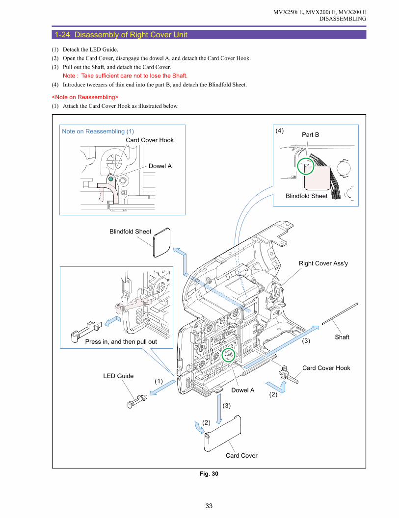
MVX250i E, MVX200i E, MVX200 EDISASSEMBLING
33
1-24 Disassembly of Right Cover Unit
(1) Detach the LED Guide.
(2) Open the Card Cover, disengage the dowel A, and detach the Card Cover Hook.
(3) Pull out the Shaft, and detach the Card Cover.
Note : Take sufficient care not to lose the Shaft.
(4) Introduce tweezers of thin end into the part B, and detach the Blindfold Sheet.
<Note on Reassembling>
(1) Attach the Card Cover Hook as illustrated below.
Fig. 30
Note on Reassembling (1)
(1)
(2)
(2)
(3)
(3)
LED Guide
Shaft
Card Cover
Card Cover Hook
Card Cover Hook
Dowel A
Dowel A
Press in, and then pull out
Part B(4)
Right Cover Ass'y
Blindfold Sheet
Blindfold Sheet

MVX250i E, MVX200i E, MVX200 EDISASSEMBLING
34
1-25 Disassembly of LCD Unit - 1
(1) Turn the LCD Hinge Unit through an angle of 90º, and remove two screws (g × 2).
(2) Disengage the claws A, B, C and D in that order, and detach the LCD Top Cover.
Note : Take care not to damage the claw hooking parts E and F of the LCD Bottom Cover.
(3) Disconnect the CN901 and CN903, and then detach the LCD Hinge Unit and the LCD DETECT FPC.
<Note on Reassembling>
(1) Attach the LCD Top Cover as illustrated below.
Fig. 31
g4mm
MetalM1.7
Note on Reassembling (1)
(1)
Claw A
Claw C
Claw DClaw B
Insert the IC part of the DETECT FPCinto the groove.
Fold a surplus part of the flexible cable inside.
(2)
E
F
(3)
(3)
(3)
(3)
CN903
CN901
LCD Hinge Unit
LCD Top Cover
LCD DETECT FPC
(1) - g
(1) - g

MVX250i E, MVX200i E, MVX200 EDISASSEMBLING
35
1-26 Disassembly of LCD Unit - 2
(1) Remove solder (α) (three points), disconnect the LCD Sheet, UL Tape, CN902. Then, detach the LCD P.C.B., the LCD Holder, the
Back Light Ass’y, and the LCD Ass’y.
(2) Disengage the claw A, and detach the LCD Open Knob, the Shaft, and the Spring.
Fig. 32
(1)
(1)
(1)
(1)
(1)
(1)
(1) (2)
LCD P.C.B.
LCD Holder
Back Light Ass'y
LCD Ass'y
LCD Sheet
LCD Sheet
LCD Bottom Cover
CN902
Spring
LCD Open Knob
Shaft
(1) - α
(1) - α
(1) - α
Claw A
UL Tape

MVX250i E, MVX200i E, MVX200 EDISASSEMBLING
36
<Note on Reassembling>
(1) At the end of reassembling, solder three points (α).
(2) While holding the Shaft and Spring, attach the LCD Open Knob over the claw A.
(3) Attach the LCD Sheet and UL Tape to the position indicated in the figure below.
Fig. 33
Note on Reassembling (1) Note on Reassembling (2)
Note on Reassembling (3)
Solder α
Solder α
Claw A
Attach with reference to the plate end ofthe LCD panel, and fold a surplus part(upper, lower).
Attach with reference to the plateend of the LCD Holder, and folda surplus part.
Attach in alignment with the plateend of the LCD panel (four sheets).
Guideline forattaching UL Tape.
UL Tape (The tape may have an arbitrary width.)
Spring
Shaft
LCD OpenKnob
LCD Sheet
LCD Sheet
LCD Sheet
LCD Sheet
Fold the leadwire inside,and performsoldering.
Conceal the holesBe sure to cover part.

MVX250i E, MVX200i E, MVX200 EDISASSEMBLING
37
1-27 Disassembly of LCD Hinge Unit
(1) Remove one screw (o × 1), disengage the claws A and B, and detach the Hinge Top Cover, the Hinge Bottom Cover, and the Magnet.
(2) Detach the LCD-KEY FPC from the LCD Hinge Ass’y.
<Note on Reassembling>
(1) When using the service part LCD-KEY FPC, put “1” and “2”, “3” and “4”, and “5” and “6” on each other in a paired form, and
secure them with the Double Sided Tape on the FPC. Then, fold “7” and “8”, and secure them with the Double Sided Tape on the
FPC.
(2) Wind the LCD-KEY FPC 2 and 1/4 turns from the state illustrated below.
(3) Attach the Magnet so that the painted side (black) will be oriented as shown in the figure below.
<Instruction for Supply>
LCD winding part : Hanal FL-778 (DY9-3026-010)
Fig. 34
9mm
MetalM1.7
(self tap)
o
Note on Reassembling (1)
Note on Reassembling (2)
(1)
(1)
(2)
(1)
Claw A
Claw B
LCD-KEY FPC
LCD Hinge Ass'yHinge Top Cover
Hinge Bottom Cover
Instruction for Supply
HanalFL-778
Wind 2-1/4 turns
Fold line Folded part
Allowable deviationof attachment fromoutline: ±0.5 mm.
LCD-KEY FPC
5
31
6
2 4 8
7
(1) - o
Double Sided Tape
Double Sided Tape
Double Sided Tape
Double SidedTape
Magnet
Paint side (Black)

MVX250i E, MVX200i E, MVX200 EDISASSEMBLING
38
1-28 Disassembly of Rear Cover Unit - 1
(1) Remove two screws (n × 1, p × 1), and detach the Grip Belt Plate, the Shaft, and the Grip Belt.
(2) Remove three screws (e × 3), and detach the Battery Terminal Ass’y.
<Note on Reassembling>
(1) Attach the Battery Terminal Ass’y as illustrated below.
Fig. 35
MetalM1.7
(self tap)
4.5mm
e n4mm
MetalM1.7
(self tap)
3.5mmMetalM1.7
(self tap)
p
Note on Reassembling (1)
Grip Belt
Grip Belt Plate
Battery Terminal Ass'y
Battery Terminal Ass'y
Shaft
(1)
(1)
(1)
(2)
Run the cablethrough two hooks.
Black Yellow Red
(2) - e
(1) - n
(1) - p

MVX250i E, MVX200i E, MVX200 EDISASSEMBLING
39
1-29 Disassembly of Rear Cover Unit - 2
(1) Remove three screws (n × 2, q × 1), and detach the Power Switch Ass’y.
(2) Remove one screw (n × 1), and detach the Strap Plate.
(3) Remove one screw (n × 1), and detach the Eject Holder, the Spring, and the Eject Knob.
Note : Take care not to lose the Spring.
<Instruction for Supply>
Entire surface of Spring : Hanal FL-778 (DY9-3026-010)
Fig. 36
MetalM1.7
(self tap)
4.5mm
qn
5.5mm
MetalM1.7
(self tap)
Spring
Rear Cover
Power Switch Ass'y
Eject Holder
Eject Knob
(1)
(3)
(2)
Strap PlateInstruction for Supply
Hanal FL-778
(3) - n
(2) - n
(1) - n
(1) - n
(1) - q
Spring

MVX250i E, MVX200i E, MVX200 EDISASSEMBLING
40
1-30 Disassembly of CVF Unit - 1
(1) Detach the UL Tape from the CAV-CVF FPC, and turn up the CVF.
(2) Detach the FPC Holder.
Note : When detaching the FPC Holder, take the following steps.
1. Disengage the claw A.
2. Using tweezers or the like, disengage the claw B from the back side. Detach the FPC Holder while sliding it.
At this step, take care not to damage the flexible cable.
(3) Detach the Dust Cover.
<Note on Reassembling>
(1) Secure the CAV-CVF FPC with the UL Tape as illustrated below.
Fig. 37
Note Note on Reassembling (1)
FPC Holder
Claw B
Claw A
Claw B
Claw A
CAV-CVF FPC UL Tape (13 × 50)
Dust Cover
CVF Hinge Ass'y
(3)
(1)
(2) UL Tape (13 × 50)
FPC Holder

MVX250i E, MVX200i E, MVX200 EDISASSEMBLING
41
1-31 Disassembly of CVF Unit - 2
(1) Remove two screws (k × 2), and detach the CVF Bottom Cover and the CVF Click Plate.
Note : Disengage the dowel A, and detach the CVF Click Plate while sliding it.
(2) Remove one screw (e × 1), and detach the CVF Click Spring.
(3) Detach the CVF Inner part.
Note : Using tweezers or the like, detach the CVF Inner part while pushing it upward as illustrated below.
Fig. 38
ke2.5mm
MetalM1.7
4mm
MetalM1.7
(self tap)
Note
Note
CVF Click Plate
CVF Bottom Cover
CVF Click Spring
(3)(1)
(2)
(2) - e
(1) - k
Dowel A
CVF Inner Part
Pull out
Push UP
Tweezers
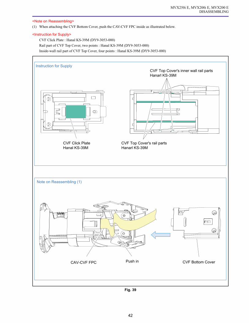
MVX250i E, MVX200i E, MVX200 EDISASSEMBLING
42
<Note on Reassembling>
(1) When attaching the CVF Bottom Cover, push the CAV-CVF FPC inside as illustrated below.
<Instruction for Supply>
CVF Click Plate : Hanal KS-39M (DY9-3053-000)
Rail part of CVF Top Cover, two points : Hanal KS-39M (DY9-3053-000)
Inside-wall rail part of CVF Top Cover, four points : Hanal KS-39M (DY9-3053-000)
Fig. 39
Note on Reassembling (1)
CAV-CVF FPC CVF Bottom CoverPush in
CVF Click PlateHanal KS-39M
Instruction for Supply
CVF Top Cover's rail partsHanarl KS-39M
CVF Top Cover's inner wall rail partsHanarl KS-39M

MVX250i E, MVX200i E, MVX200 EDISASSEMBLING
43
1-32 Disassembly of CVF Unit - 3
(1) Disengage two claws A, and detach the CVF Inner Bottom Cover Ass’y.
(2) Remove two screws (k × 2), and detach the CVF Hinge Unit.
<Notes on Reassembling>
(1) Attach the CVF Inner Bottom Cover Ass’y as illustrated below.
Fig. 40
k2.5mm
MetalM1.7
Note on Reassembling (1)
First engage the Eye Piece side (claw B)and engage the claw A.
Claw A
Claw A
(2)CVF Top Cover
CVF Hinge Unit
Running CVF FPCbetween the ribs.
Claw B
Eye Piece
CVF FPC
(2) - k
(1)
CVF Inner Bottom Cover Ass'y

MVX250i E, MVX200i E, MVX200 EDISASSEMBLING
44
1-33 Disassembly of CVF Unit - 4
(1) Disengage two claws A, and detach the CAV-CVF FPC, the CVF Mask, and the other parts between them.
(2) Disengage two claws B, and detach the CVF Reflector from the CVF P.C.B.
(3) Disconnect the CN4101 and CN4102, and detach the CAV-CVF FPC and the CVF Ass’y.
<Note on Reassembling>
(1) When mounting the CVF Reflector, push the CVF Mask, CVF Ass’y, Cushion and Diffuser lightly in the arrow direction.
(2) Insert the CVF Ass’y flexible cable under the rib of the CVF Inner Cover as illustrated below.
Fig. 41
Note on Reassembling (1)
Note on Reassembling (2)
Claw B
Claw B
Claws A
(3)(3)
CN4102
CN4101
CAV-CVF FPC
CVF Inner Cover
CVF Mask
CVF Ass'y
Cushion
Diffuser
CVF Reflector
CVF P.C.B.
CVF Reflector Part
Push in
Ribs
(2)

MVX250i E, MVX200i E, MVX200 EDISASSEMBLING
45
1-34 Disassembly of CVF Unit - 5
(1) Remove one screw (r × 1), and detach the CVF Knob, Rubber, and CVF Lens Holder.
(2) Disengage two claws A, and detach the Lens1 and Lens2.
<Note on Reassembling>
(1) When attaching the Lens1 and Lens2 to the CVF Lens Holder, take care not to mistake the orientation of the Lens1/Lens2.
(2) When attaching the CVF Knob, engage the dowel of the CVF Lens Holder as illustrated below. Take care not to forget to attach the
Rubber.
<Instruction for Supply>
CVF Inner Cover inside, 8 points on sliding rail part : Hanal KS-39M (DY9-3053-000)
Rubber top surface : Hanal KS-39M (DY9-3053-000)
r2.3mm
MetalM1.7
Steped Screw
Instruction for SupplyNote on Reassembling (2)
Note on Reassembling (1)
CVF Inner Cover
(1)
CVF Knob
(1)
(2)
Claw A
Rubber
CVF Lens Holder
Lens 1
Lens 2
CVF Lens Holder
CVF Inner Cover Lens 2Lens 1
Rubber top surface
Hanal : KS-39M
Sliding parts of rail
CVF Knob
CVF Lens Holder
(1) - r
Rubber
Sliding parts of rail
Fig. 42

MVX250i E, MVX200i E, MVX200 EDISASSEMBLING
46
1-35 Disassembly of Camera Unit
(1) Detach the CCD-CAV FPC from the CN1070.
(2) Remove two screws (f × 2), and detach the CCD P.C.B., CCD Ass’y, Rubber, and IR Filter.
(3) Unsolder the parts A, and detach the CCD Ass’y from the CCD P.C.B.
<Notes on Reassembling>
(1) When soldering on the CCD P.C.B., secure the CCD Ass’y and the CCD P.C.B. with two screws (f × 2).
Fig. 43
f
5mm
MetalM1.7
(self tap)
Face thickside towardCCD side
IR Filter
IR Filter
Lens Unit
Lens
Rubber
CCD Ass'y
Parts A
CCD
CCD P.C.B.
CCD P.C.B.
(3)
(3)
(2)
CCD - CAV FPCCN1070
(1)
(1) - f

MVX250i E, MVX200i E, MVX200 EDISASSEMBLING
47
1-36 Disassembly of Lens Unit
(1) Remove seven screws (n × 3, p × 2, s × 2), and detach the IG Meter Ass’y.
(2) Unsolder the part (α), and detach the PZ Motor and AF Motor.
<Note on Reassembling>
(1) Run the flexible cable through the groove of part A.
Fig. 44
MetalM1.7
(self tap)
4.5mm
n
MetalM1.7
(self tap)
4.5mm
s
3.5mmMetalM1.7
(self tap)
p
Note on Reassembling (1)
(2) - α
(2) - α
(2) - α
(2) - α(1)
(2)
(2)PZ Motor
IG Meter Ass'y
AF Motor
A
(1) - s
(1) - n
(1) - p(1) - p
(1) - n

MVX250i E, MVX200i E, MVX200 EDISASSEMBLING
48
1-37 List of Screws Used
PARTS NO. PARTS NO. ILLUSTS
YM
BO
LPARTS NO. REMARKS ILLUST
SY
MB
OL
a
b
c
d
e
f
g
h
i
j
XA1-7170-507 M1.7-5.0mm (Metal)
XA1-7170-407 M1.7-4.0mm (Metal)
M1.7-3.5mm (Metal)
XA1-7170-607 M1.7-5.0mm (Metal)
M1.7-2.5mm (Metal)
M1.7-5.5mm (Metal)
M1.7-3.0mm (Metal)
XA1-3170-507
XA4-9170-407
XA1-7170-307
M1.7-2.0mm (Metal)
Flat Head Screw
M1.7-5.0mm (Metal)XA1-7170-257
DA3-1026-000Steped Screw
M1.7-4.5mm (Metal)
XA4-9170-907
XA4-5170-457
Self Tap
M1.7-9.0mm (Metal)
XA4-9170-357Self Tap
M1.7-3.5mm (Metal)
XA4-9170-557Self Tap
M1.7-5.5mm (Metal)
Steped Screw
M1.7-2.3mm (Metal)
Self Tap
M1.7-4.5mm (Metal)
XA9-1166-000
XA9-1167-000Steped Screw
M1.7-3.4mm (Metal)
XA1-7170-557
XA1-7170-207
XA4-9170-457Self Tap
M1.7-4.5mm (Metal)
XA4-9170-507Self Tap
M1.7-5.0mm (Metal)
Self Tap
M1.7-4.0mm (Metal)
XA1-7170-357
k
l
m
n
o
p
q
r
s
t XA4-9170-459Self Tap
M1.7-4.5mm Black
9mm
3.4mm
4.5mm
4.5mm
2.5mm
4mm
5mm
3.5mm
5.5mm
2mm
5mm
6mm
3mm
5mm
4mm
4.5mm
5.5mm
3.5mm
2.3mm
4.5mm

MVX250i E, MVX200i E, MVX200 EDISASSEMBLING
49
1-38 List of Disassembly Photos
Right Side Top Side
Front Side Camera / Recorder Unit
Camera Unit Front Cover Unit

MVX250i E, MVX200i E, MVX200 EDISASSEMBLING
50
Left Cover Unit Right Cover Unit
Rear Cover Unit LCD Unit

SERVICE MODE · ADJUSTMENT
CONTENTS
1. Maintenance Tools ------------------------------------------------------------------------------------------------------------------------------- 1
1-1 List of Maintenance Tools -------------------------------------------------------------------------------------------------------------- 1
2. Setting ------------------------------------------------------------------------------------------------------------------------------------------- 2
2-1 Using the Extension Connectors ------------------------------------------------------------------------------------------------------ 2
2-2 Setting A ----------------------------------------------------------------------------------------------------------------------------------- 3
2-3 Setting B ----------------------------------------------------------------------------------------------------------------------------------- 4
3. Service Modes ------------------------------------------------------------------------------------------------------------------------------------ 5
3-1 Outline ------------------------------------------------------------------------------------------------------------------------------------- 5
3-2 How to Change Over to Service Mode ------------------------------------------------------------------------------------------------ 5
3-3 How to Operate Wireless Remote Controller in Service Mode -------------------------------------------------------------------- 6
3-4 Indication in Service Mode ------------------------------------------------------------------------------------------------------------- 7
4. Description of Service Modes ------------------------------------------------------------------------------------------------------------------ 8
4-1 Error Rate --------------------------------------------------------------------------------------------------------------------------------- 8
4-2 Mechanical Error Indication ------------------------------------------------------------------------------------------------------------ 9
4-2-1 Mechanical Error Normal Mode --------------------------------------------------------------------------------------------9
4-3 Cleaning Mode ------------------------------------------------------------------------------------------------------------------------- 10
4-4 Commands Particular to Camera ----------------------------------------------------------------------------------------------------- 10
4-5 Checking the Lens Resetting --------------------------------------------------------------------------------------------------------- 11
4-6 Functional Check of Control Keys and Switches ---------------------------------------------------------------------------------- 12
4-6-1 MODE MI-COM Input Port ----------------------------------------------------------------------------------------------- 12
4-6-2 MODE MI-COM A/D Port ------------------------------------------------------------------------------------------------ 12
4-6-3 FR MI-COM Input Port ---------------------------------------------------------------------------------------------------- 13
4-6-4 FR MI-COM A/D Port ----------------------------------------------------------------------------------------------------- 13
5. Adjustment Procedures ------------------------------------------------------------------------------------------------------------------------ 14
5-1 Adjustment Items in Part Replacement ---------------------------------------------------------------------------------------------- 14
5-1-1 Indication in Service Mode ------------------------------------------------------------------------------------------------ 16
5-2 AF Section Adjustment ---------------------------------------------------------------------------------------------------------------- 17
5-2-1 CZ Automatic Adjustment ------------------------------------------------------------------------------------------------- 18
5-2-2 Cam Correction (AUTO) --------------------------------------------------------------------------------------------------- 19
5-3 IS Section Adjustment ----------------------------------------------------------------------------------------------------------------- 20
5-3-1 Gyro Offset Adjustment ---------------------------------------------------------------------------------------------------- 20
5-3-2 Gyro Gain Check ------------------------------------------------------------------------------------------------------------ 20
5-3-3 Virtual EEPROM and Flash Memory Writing -------------------------------------------------------------------------- 21
5-4 Camera Section Adjustment ---------------------------------------------------------------------------------------------------------- 22
5-4-1 Iris Adjustment -------------------------------------------------------------------------------------------------------------- 22
5-4-2 WB Adjustment (1) --------------------------------------------------------------------------------------------------------- 22
5-4-3 Color Balance Adjustment ------------------------------------------------------------------------------------------------- 23
5-4-4 WB Adjustment (2) --------------------------------------------------------------------------------------------------------- 23
5-4-5 WB Adjustment (3) --------------------------------------------------------------------------------------------------------- 24
5-4-6 Virtual EEPROM and Flash Memory Writing -------------------------------------------------------------------------- 24
5-5 CCD Pixel Missing Compensation -------------------------------------------------------------------------------------------------- 25
5-5-1 CCD Pixel Missing Compensation (AUTO) ---------------------------------------------------------------------------- 25
5-6 CVF Adjustment ------------------------------------------------------------------------------------------------------------------------ 26
5-6-1 Forced CVF ON ------------------------------------------------------------------------------------------------------------- 26
5-6-2 CVF Frequency Adjustment ----------------------------------------------------------------------------------------------- 26
5-6-3 Contrast Adjustment -------------------------------------------------------------------------------------------------------- 27
5-6-4 Brightness Adjustment ------------------------------------------------------------------------------------------------------ 28

5-6-5 Black Limiter Level Adjustment ------------------------------------------------------------------------------------------ 29
5-6-6 COM Amplitude Adjustment ---------------------------------------------------------------------------------------------- 30
5-6-7 COM-DC Level Adjustment ----------------------------------------------------------------------------------------------- 31
5-6-8 Flash Memory Writing ----------------------------------------------------------------------------------------------------- 32
5-6-9 Release of Forced CVF ON------------------------------------------------------------------------------------------------ 32
5-7 Color Balance Check ------------------------------------------------------------------------------------------------------------------ 33
5-8 Recorder Section Adjustment --------------------------------------------------------------------------------------------------------- 34
5-8-0 LCD PCB Setting Destination --------------------------------------------------------------------------------------------- 34
5-8-1 SWP Adjustment ------------------------------------------------------------------------------------------------------------ 34
5-8-2 C. FG Adjustment ----------------------------------------------------------------------------------------------------------- 34
5-8-3 Automatic Adjustment of Reel FG ---------------------------------------------------------------------------------------- 35
5-8-4 Battery Voltage Drop Adjustment ----------------------------------------------------------------------------------------- 35
5-8-5 Flash Memory Writing ----------------------------------------------------------------------------------------------------- 35
5-9 Tape Path Adjustment ------------------------------------------------------------------------------------------------------------------ 36
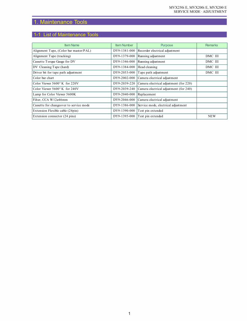
MVX250i E, MVX200i E, MVX200 ESERVICE MODE · ADJUSTMENT
1
1. Maintenance Tools
1-1 List of Maintenance Tools
Item Name Item Number Purpose Remarks
Alignment Tape, (Color bar master/PAL) DY9-1381-000 Recorder electrical adjustment
Alignment Tape (tracking) DY9-1379-000 Running adjustment DMC III
Cassette Torque Gauge for DV DY9-1346-000 Running adjustment DMC III
DV Cleaning Tape (hard) DY9-1384-000 Head cleaning DMC III
Driver bit for tape path adjustment DY9-2053-000 Tape path adjustment DMC III
Color bar chart DY9-2002-000 Camera electrical adjustment
Color Viewer 5600° K for 220V DY9-2039-220 Camera electrical adjustment (for 220)
Color Viewer 5600° K for 240V DY9-2039-240 Camera electrical adjustment (for 240)
Lamp for Color Viewer 5600K DY9-2040-000 Replacement
Filter, CCA W12ø46mm DY9-2046-000 Camera electrical adjustment
Cassette for changeover to service mode DY9-1386-000 Service mode, electrical adjustment
Extension Flexible cable (24pin) DY9-1390-000 Test pin extended
Extension connector (24 pins) DY9-1395-000 Test pin extended NEW

MVX250i E, MVX200i E, MVX200 ESERVICE MODE · ADJUSTMENT
2
2. Setting
(1) Adjustments other than DMC-III : Perform adjustments in the product state.
(2) Tracking adjustment (DMC-III) and Envelope check : Perform them with the Setting A.
(3) Adjustments related to DMC-III other than Tracking adjustment, tape path system check and tape path system cleaning : Perform
them with the Setting B.
2-1 Using the Extension Connectors
(1) Attach the two extension connectors (DY9-1395-000) to the
extension flexible cable (DY9-1390-000)
Important
Secure the two connectors with tape as shown in
the figure. (When removing the extension con-
nector assembly from the main unit after use, the
connector coupling may be detached in some
cases. If the connector located on the main unit
side comes off, it becomes impossible to remove
it from the main unit. To prevent this, secure the
connectors with tape beforehand.)
(2) Detach the blindfold sheet.
(3) Connect the extension connectors to the CN2900.
<Signals used>
Fig. 3
Pin No.Signal
Designation
2 EVF HD
3 GND
15 SWP
19 PBRF
Pin No.Signal
Designation
21 EVF R
22 EVF COM
23 EVF G
24 EVF B
Fig. 2
DY9-1390-000
DY9-1395-000
Secure with tape.
DY9-1395-000
Fig. 1
BLINDFOLD SHEET

MVX250i E, MVX200i E, MVX200 ESERVICE MODE · ADJUSTMENT
3
2-2 Setting A
Envelope observation)
(1) Observe a PB-RF signal output from each extension connector that has been attached in 2-1 “Using the Extension Connectors”.
Tracking Adjustment)
(1) Detach the regulation cover.
* : To avoid flawing the regulation cover, detach it from the inside of the left cover as illustrated.
(2) While observing a PB-RF signal, adjust the post to eliminate
fluctuations of the envelope.
Note : When the tracking adjustment is going to be per-
formed, refer to “5-9 Tape Path Adjustment” on
p.36.
Fig. 4
REGULATION COVER
LEFT COVER
REGULATION COVER
Fig. 5
ADJUSTMENT DRIVER(DY9-2053-000)

MVX250i E, MVX200i E, MVX200 ESERVICE MODE · ADJUSTMENT
4
2-3 Setting B
(1) Remove the FRONT COVER, REAR COVER, LEFT COVER UNIT, RIGHT COVER UNIT referring to “Disassembling”.
Note 1 : Referring to Fig.5, connect the required cables.
Note 2 : Observe the signal in the same manner as that for setting A.
Note 3 : For ejection, use the switch concerned on the P.C.B. For mode transition, use the wireless remote controller.
Fig. 6
MONITOR TV
WIRELESS CONTROLLER
CA-570
LEFT COVER UNIT
FRONT COVER UNIT
FRONT COVERUNIT
REAR COVER UNIT
REAR COVER UNIT
MAIN P.C.B.CN100
MAIN P.C.B.CN101
JACK1 P.C.B.CN51
JACK1 P.C.B.CN3211
JACK1 P.C.B.CN51
MAIN P.C.B.CN2101
JACK1 P.C.B.CN3211
MAIN P.C.B.CN3201
MAIN P.C.B.CN3201
MAIN P.C.B.CN101
JACK2 P.C.B.EJECT SWITCH

MVX250i E, MVX200i E, MVX200 ESERVICE MODE · ADJUSTMENT
5
3. Service Modes
3-1 Outline
(1) The service mode in this equipment uses the wireless remote controller. (To be used in remote control code 2)
(2) For changeover to the service mode, a dedicated tool (CASSETTE, SERVICE MODE: DY9-1386-000) is required in addition to
the wireless remote controller.
(3) Mode changeover is available between the service mode and the normal mode using the “Audio dubbing” and “SLOW” keys of the
wireless remote controller.
As long as power is ON, the service mode is available even if the “CASSETTE, SERVICE MODE” is removed.
(4) In the service mode, changeover of the main unit operation mode can be handled using the keys on the main unit and the remote control
mode 1.
(5) In the service mode, safety functions such as for mechanical error detection, DEW detection and low voltage detection are canceled.
(6) In the service mode, the LCD mirror function is canceled.
3-2 How to Change Over to Service Mode
(1) Set the cassette for changeover to service mode (DY9-1386-
000) in the equipment and load the data.
(2) Press the “Dubbing” key on the wireless remote controller
that is set at Remote controller code 2.
* To changeover to Remote controller code 2, press
“Remote controller setting” and “Zoom T” keys si-
multaneously for 2 sec.
* The remote controller code setting on the DVC main
unit is operable both at remote controller codes 1
and 2.
(3) Now the changeover to the service mode has been completed
and the SERVICE MODE appears on the screen.
* Pressing the “SLOW” key performs the changeover
to the normal mode from the service mode.
As long as the power supply is ON, the service mode
is available by setting the “Audio dubbing” key even
if the cassette for transfer to service mode is re-
moved.
Fig. 7
DY9-1386-000
Fig. 8

MVX250i E, MVX200i E, MVX200 ESERVICE MODE · ADJUSTMENT
6
3-3 How to Operate Wireless Remote Controller in Service Mode
(1) To use the wireless remote controller in the service mode, set it at Remote controller code 2.
* To changeover to Remote controller code 2, press the “Remote controller setting” and “Zoom T” keys simulta-
neously for 2 sec.
Fig. 9
3. START/STOP
2. SLOW 1. DUBBING
5. SEARCH -
4. SERCH +
8. FF
11. PLAY
6. FRAME +
14. × 2
12. STOP
10. SERCH SELECT
9. REW
7. FRAME -
13. PAUSE
Remote ControllerCode 2 setting
No. Key Designation (in Normal Mode) Key Designation (in Service Mode) Function
1 DUBBING SERVICE MODE Change over to service mode
2 SLOW NORMAL MODE Change over to normal mode
3 START/STOP CS+ Increases CS by 1.
4 SEARCH + FUNCTION + Increases FUNCTION by 1.
5 SEARCH - FUNCTION - Decreases FUNCTION by 1.
6 FRAME + HIGH ADDRESS + Increases HIGH ADDRESS by 1.
7 FRAME - HIGH ADDRESS - Decreases HIGH ADDRESS by 1.
8 FF ADDRESS + Increases ADDRESS by 1.
9 REW ADDRESS - Decreases ADDRESS by 1.
10 SEARCH SELECT MODE SELECT Change over to RD/WR mode
11 PLAY DATA + Increases DATA by 1.
12 STOP DATA - Decreases DATA by 1.
13 PAUSE STORE Defines/w rites DATA.
14 2 EJECT Performs EJECT.

MVX250i E, MVX200i E, MVX200 ESERVICE MODE · ADJUSTMENT
7
3-4 Indication in Service Mode
Shown below are the indications in the service mode.
1. Indicates that the service mode is currently selected. (“SERV”)
2. MODE : Indicates the MODE currently selected. (RD/WR/ST)
3. Indicates for which block the command is specified. (MA,MD, CA, CD, etc.)
4. CS : Indicates the Chip Select currently specified. (0~F)
5. Function : Indicates the Function currently selected. (00~FF)
6. ADDR : Indicates the ADDRESS currently selected. (0000~FFFF)
7. DT : Indicate, in hexadecimal representation, the DATA currently being read or set. (00~FF)
8. Indicates the mechanical status. (POPUP, STBY, LOAD1, LOAD2, STOP, PLAY)
9. Indicates the absolute track No.
10. Indicates the mechanical error. (Main power supply backup)
11. Indicates mechanical error history (LITHIUM 3V battery backup)
12. Indicates the version of the MAIN program in the FR MI-COM.
13. Indicates the version of the MODE MI-COM.
14. Indicates the version of the CAMERA program in the FR MI-COM.
15. Indicates the version of the CARD program in the FR MI-COM.
16. E0 : Indicates the error rate of the track that is traced in the CH0 (Low ch) head.
17. E1 : Indicates the error rate of the track that is traced in the CH1 (High ch) head.
18. Data Write status (00: READ mode, 04 : Write preparation, OC : Write execution)
Fig. 10
14
2
3
5 6
7
8 9
10
11
12
13
14
15
16 17
18

MVX250i E, MVX200i E, MVX200 ESERVICE MODE · ADJUSTMENT
8
4. Description of Service Modes
4-1 Error Rate
<Generals>
(1) A VIDEO error rate (VIDEO + AUDIO) and an AUDIO error rate can be checked.
(2) Note that the error rate is worsened on occurrence of failure in tape running, deterioration of tape, decreased in head output, failure
in head amplifier, improper drum shield, etc.
<How to read a VIDEO error rate>
An average error rate on 64-track AUDIO+VIDEO sector is indi-
cated in exponential representation.
Example) ‘25’ is indicated:
Error rate = 2×10 -5
<How to read an AUDIO error rate>
To read error rate of AUDIO track, follow the procedures in the
table below.
The number of erroneous sync block of 64-track AUDIO sync
blocks is indicated in two hexadecimal digits.
(FF limitation is imposed on a value exceeding 255.)
Example) ‘23’is indicated:
Number of erroneous sync blocks = 35
Important
After the adjustment, set the DT to the product setting . (press STORE key at 1 of STEP 1 state.)
<Change to an AUDIO error rate>
In the product specifications, the error rate on both chan-
nels in self -recording LP playback is as follows :
Error rate =28H or less
(Number of erroneous sync blocks = 40 or less)
Fig. 11
Low ch. High ch.
EO 2 5 E1
2 × 10⁻⁵
Fig. 12
Low ch. High ch.
(hexadecimal)
(decimal)
AO 2 3 A1
2
(2 ×16)+ 3 = 35
3
STEP PROCEDURE Microcomputer operation
CS Function ADDR MODE DT
1 1) Make setting shown at right. 0 10 001D ST 00 03 Product setting
2) Execute STORE. (Press PAUSE.) RD 03 Audio error rate indication
Remarks) Selecting DT back to "0"makes a return to Audio + Video error rate.
MONITOR

MVX250i E, MVX200i E, MVX200 ESERVICE MODE · ADJUSTMENT
9
4-2 Mechanical Error Indication
<Outline>
(1) On occurrence of a mechanical error, the conditions of the error can be checked in the service mode. (Normal indication mode and
analysis mode available)
(2) In the normal indication mode of the mechanical error, two types of indications appear on the service mode initial screen: the data
indication retained only by the main battery and the error history data indication backed up by LITHIUM 3V.
(3) The data backed up by the LITHIUM 3V can be reset by the STEP-1 operation shown below.
4-2-1 Mechanical Error Normal Mode
STEP PROCEDURE Microcomputer operation
CS Function ADDR MODE DT
1 1) Make setting shown at right. 0 08 0008 ST 00
2) Execute STORE. (Press PAUSE.) RD Completion of backup data resetting
MONITOR
Fig. 13
EBDCSTLD
: TAPE END: TAPE TOP: DRUM ERROR: CAPSTAN ERROR: S-REEL ERROR: T- REEL ERROR: LOADING MTR ERROR: DEW ERROR
Relevant errors are highlighted in purple.

MVX250i E, MVX200i E, MVX200 ESERVICE MODE · ADJUSTMENT
10
4-3 Cleaning Mode
When cleaning the head with hard-type cleaning tape (DY9-1384-000), set up the cleaning mode according to the procedure given
below.
Note : After head cleaning, be sure to restore the settings to normal.
4-4 Commands Particular to Camera
<Outline>
(1) The commands particular to camera are provided for checking the operation.
(2) Make preparation according to the table below and carry out the desired commands particular to camera.
(3) To restore any setting back to the original status, press the PAUSE key (STORE) for each item again in the “ST” mode.
Turning the power OFF/ON resets all the settings.
STEP PROCEDURE MONITOR Microcomputer operation
CS Function ADDR MODE DT
1 1) Make setting shown at right. 0 10 0111 ST --
2) Increases DT by 2. --
(Change bit-02 to 1 from 0.)
(Example: 80 82)
3) Perform STORE. (Press PAUSE key. RD -- Completion of cleaning mode setup
2 1) Change over to the normal mode and turn OFF the power supply. Resetting of cleaning mode
STEP PROCEDURE Microcomputer operation
CAM SPECIAL COMMAND CS Function ADDR MODE DT
WB SET 1) Make setting shown at right. 2 08 3300 ST --
2) Execute STORE. (Press PAUSE.) RD -- WB is set.
WB 1) Make setting shown at right. 2 08 3301 ST --
LOCK 2) Execute STORE. (Press PAUSE.) RD -- WB is locked.
WB 1) Make setting shown at right. 2 08 3302 ST --
TURBO 2) Execute STORE. (Press PAUSE.) RD -- WB high-speed setting mode
WB 1) Make setting shown at right. 2 08 3303 ST --
OUTDOOR 2) Execute STORE. (Press PAUSE.) RD -- WB outdoor mode
WB 1) Make setting shown at right. 2 08 3304 ST --
INDOOR 2) Execute STORE. (Press PAUSE.) RD -- WB indoor mode
IRIS 1) Make setting shown at right. 2 08 3305 ST --
OPEN 2) Execute STORE. (Press PAUSE.) RD -- The iris is opened forcibly.
IRIS 1) Make setting shown at right. 2 08 3306 ST --
CLOSE 2) Execute STORE. (Press PAUSE.) RD -- The iris is closed forcibly.
ND ON 1) Make setting shown at right. 2 08 3307 ST --
2) Execute STORE. (Press PAUSE.) RD -- ND inserted
ND OFF 1) Make setting shown at right. 2 08 3308 ST --
2) Execute STORE. (Press PAUSE.) RD -- ND in standby state
AGC 1) Make setting shown at right. 2 08 3309 ST --
MAX 2) Execute STORE. (Press PAUSE.) RD -- A value of AGC gain is maximized.
AGC 1) Make setting shown at right. 2 08 330A ST --
MIN 2) Execute STORE. (Press PAUSE.) RD -- A value of AGC gain is minimized.
COLOR 1) Make setting shown at right. 2 08 330B ST --
BAR 2) Execute STORE. (Press PAUSE.) RD -- Outputs color bar from DIGIC DV.
White 1) Make setting shown at right. 2 08 330C ST --
100% 2) Execute STORE. (Press PAUSE.) RD -- Outputs white 100% from DIGIC DV.
White 1) Make setting shown at right. 2 08 330D ST --
50% 2) Execute STORE. (Press PAUSE.) RD -- Outputs white 50% from DIGIC DV.
MONITOR

MVX250i E, MVX200i E, MVX200 ESERVICE MODE · ADJUSTMENT
11
4-5 Checking the Lens Resetting
<Generals>
(1) Set up addresses according to the table shown below. Thus, using data marked with the arrows in the figure below, you can check
whether lens resetting has been completed or not.
* In case of 40 or 44, the zoom lens has not yet been reset.
* In case of 80 or 84, the focus lens has not yet been reset.
STEP PROCEDURE Microcomputer operation
CS Function ADDR MODE DT
1 1) Make setting shown at right. 2 00 8300 RD -- RAM data indication
MONITOR
Fig. 14

MVX250i E, MVX200i E, MVX200 ESERVICE MODE · ADJUSTMENT
12
4-6 Functional Check of Control Keys and Switches
<Generals>
(1) The MODE and FR MI-COM terminals can be checked in the service mode. With this function, the key-related operations and the
connections between the keys and the MI-COM terminals can be checked in the product state.
(2) Perform the check in the RD mode.
4-6-1 MODE MI-COM Input Port
4-6-2 MODE MI-COM A/D Port
PIN NAME Description CS Function ADDR
95 KEY AD3 KEY AD 3 1 02 0000 MENU(00) SET(40)
93 KEY AD2 KEY AD 2 1 02 0001 STOP(00) PLAY(40) FF(85)
92 KEY AD1 KEY AD 1 1 02 0002 DE ON/OFF(00) DE SEL. (40) AE(85)
91 KEY AD0 KEY AD 0 1 02 0003 D.CODE(00) C.MIX(40) REW(85)
88 Batt Info A/D Battery temperature detection 1 02 0006
87 Batt A/D Battery voltage detection 1 02 0007 Low(00) High(FF)
Low(FF) High(00)
AD DATA (00~FF)
PIN NAME Description CS Function ADDR DATA BIT
25 Li3V DetectDetection of decrease in lithiumbattery voltage 1 01 0007 3
42 Dial CCW Switch Select Dial ↓ 1 01 0005 2
43 Dial CW Switch Select Dial 1 01 0005 1
64 PANEL Open Switch LCD open detection 1 01 0002 6
65 PANEL Bottom/Top Switch LCD reverse detection 1 01 0002 5
66 Eject Switch EJECT SW detection 1 01 0002 4
67 Cassette In Switch Cassette IN SW detection 1 01 0002 3
68 Photo Switch Full pressing of Photo SW 1 01 0002 2
69 Half Photo Switch Halfway pressing of Photo SW 1 01 0002 1
70 START STOP Start / Stop SW 1 01 0002 0
71 DC J DET DC JACK detection 1 01 0001 7
75 PAE/GREEN SW P.AE/GREEN SW 1 01 0001 3
76 VTR Power Switch POWER SW (VCR) 1 01 0001 2
77 CAM Power Switch POWER SW (CAMERA) 1 01 0001 1
78 T/C PW SW Tape/Card SW 1 01 0001 0
80 DC V DET Input voltage from DC jack 1 01 0000 6
82 KEY AD4 REC PAUSE KEY 1 01 0000 4

MVX250i E, MVX200i E, MVX200 ESERVICE MODE · ADJUSTMENT
13
4-6-3 FR MI-COM Input Port
4-6-4 FR MI-COM A/D Port
PIN NAME Description CS Function ADDRAA16 ZOOMKEY Zoom key output 0 02 0002 TELE
sideWIDEside
AC17 TEMP Lens thermometer output 0 02 0003
X15 Y GYRO YAW side GYRO output 0 02 0004
AB16 P GYRO PITCH side GYRO output 0 02 0005
Y15 I ENC IRIS ENC output 0 02 0006 Small diaphragm Open
AA15 MSW AD Mechanical position 0 02 000A
AC15 DEW DEW detection 0 02 000BY14 CAS IN Cassette detection 0 02 000C Cassette
insertedCassettenot inserted
AC14 WIDE DET Wide signal detection 0 02 000D
AA14 TAPE T OP Beginning detection 0 02 000E
AB14 TAPE END Ending detection 0 02 000F
AD DATA (00~FF)
Intermediate
PIN NAME Description CS Function ADDR DATA BIT
P6 SDET S JACK detection 0 01 0000 5
W1 USB DET USB Detect 0 01 0009 5
X5 CARD DET CARD detection 0 01 0009 4
E3 REC PROOF Tape recording inhibition 0 01 000A 7
U6 CARD PRO Card recording inhibited 0 01 000A 2

MVX250i E, MVX200i E, MVX200 ESERVICE MODE · ADJUSTMENT
14
5. Adjustment Procedures
5-1 Adjustment Items in Part Replacement
After replacement of major parts, carry out adjustment referring to the table shown below. Note that the following table shows minimum
required adjustments to be performed after replacing any major part. In case that two or more parts have been replaced or any faulty
condition has occurred, take a proper adjustment procedure accordingly.
: Adjustmentrequired
Camera system
Part name
No. Adjustment itemLens
JACK1PCB
CCD CVFMAINPCB
CAVPCB
Adjustment setting
5-2 AF section
5-2-1 CZ Automatic Adjustment Product condition
5-2-2 Cam Correction (AUTO) Product condition
5-3 IS section
5-3-1 Gyro Offset Adjustment Product condition
5-3-2 Gyro Gain Check Product condition
5-3-3 Virtual EEPROM and Flash Memory Writing Product condition
5-4 Camera section
5-4-1 Iris Adjustment Product condition
5-4-2 WB Adjustment (1) Product condition
5-4-3 Color Balance Adjustment Product condition
5-4-4 WB Adjustment (2) Product condition
5-4-5 WB Adjustment (3) Product condition
5-4-6 Virtual EEPROM and Flash Memory Writing Product condition
5-5 CCD Pixel Missing Compensation Product condition
5-6-1 Forced CVF ON Product condition
5-6-2 CVF Frequency Adjustment Product condition
5-6-3 Contrast Adjustment Product condition
5-6-4 Brightness Adjustment Product condition
5-6-5 Black Limiter Level Adjustment Product condition
5-6-6 COM Amplitude Adjustment Product condition
5-6-7 COM-DC Level Adjustment Product condition
5-6-8 Flash Memory Writing Product condition
5-6-9 Release of Forced CVF ON Product condition
5-7 Color Balance Check Product condition
5-6 CVF Adjustment

MVX250i E, MVX200i E, MVX200 ESERVICE MODE · ADJUSTMENT
15
Recorder system
Part name
No. Adjustment item MAINPCB
DMCIII
Adjustment setting
5-8 Recorder section
5-8-0 LCD PCB Setting Destination Product condition
5-8-1 SWP Adjustment Product condition
5-8-2 C. FG Adjustment Product condition
5-8-3 Automatiac Adjustment of Reel FG Product condition
5-8-4 Battery Voltage Drop Adjustment Product condition
5-8-5 Flash Memory Writing Product condition
DMC III
5-9 Tape Path AdjustmentTape pathadjustment setting

MVX250i E, MVX200i E, MVX200 ESERVICE MODE · ADJUSTMENT
16
Fig. 15
3
1
2
4 5
8 9 10 11 12 13 6
7
5-1-1 Indication in Service Mode
Shown below are the indications in the service mode.
1. MODE : Indicates the MODE currently selected. (RD/WR/ST)
2. Indicates for which block the command is specified. (MA, MD, CA, CD, etc.)
3. CS : Indicates the Chip Select currently specified. (0~F)
4. Function : Indicates the Function currently selected. (00~FF)
5. ADDR : Indicates the ADDRESS currently selected. (0000~FFFF)
6. DT : Indicate, in hexadecimal representation, the DATA currently being read or set. (00~FF)
7. Data write status (0 : Read mode, 1 : Ready to write, C : Write execution)
8. ST : Adjustment status (02: During adjustment, 05: Adjustment OK, 09: Adjustment NG)
9. ST2 : Adjustment status (for use in AF adjustment)
At the time of IS adjustment
10. IS1 : Yaw Gyro gain
11. IS2 : Pitch Gyro gain
12. IS3 : Yaw Gyro offset
13. IS4 : Pitch Gyro offset

MVX250i E, MVX200i E, MVX200 ESERVICE MODE · ADJUSTMENT
17
5-2 AF Section Adjustment
Note)
(1) The sections 5-2-1 : CZ automatic adjustment and 5-2-2 : Cam correction (AUTO) must be executed consecutively. If they are
performed independently, the sufficient performance cannot be obtained.
Also, when section 5-2-1 : CZ automatic adjustment is completed, execute section 5-2-2 : Cam correction (AUTO) must be
executed immediately without elapse of time. If execute section 5-2-2 : Cam correction (AUTO) is executed after elapse of time
upon completion of section 5-2-1 : CZ automatic adjustment, the sufficient performance cannot be obtained.
Preparation)
(1) For CZ automatic adjustment/cam correction, set the product condition.
(2) Adjustment condition (initial condition)
Tape/Card : Tape
Program AE : Auto Mode
ZOOM : Telephoto-end
CZ adjustment chart : 2.4 ± 0.02 m from lens front
Chart luminance : 500 lux or more (High illuminance should be avoided at the wide-angle end.)
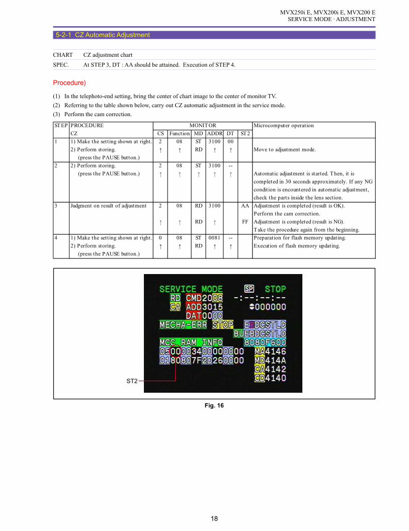
MVX250i E, MVX200i E, MVX200 ESERVICE MODE · ADJUSTMENT
18
5-2-1 CZ Automatic Adjustment
CHART CZ adjustment chart
SPEC. At STEP 3, DT : AA should be attained. Execution of STEP 4.
Procedure)
(1) In the telephoto-end setting, bring the center of chart image to the center of monitor TV.
(2) Referring to the table shown below, carry out CZ automatic adjustment in the service mode.
(3) Perform the cam correction.
Fig. 16
ST2
STEP PROCEDURE Microcomputer operation
CZ CS Function MD ADDR DT ST2
1 1) Make the setting shown at right. 2 08 ST 3100 00
2) Perform storing. ↑ ↑ RD ↑ ↑ Move to adjustment mode.
(press the PAUSE button.)
2 2) Perform storing. 2 08 ST 3100 --
(press the PAUSE button.) Automatic adjustment is started. Then, it is
completed in 30 seconds approximately. If any NG
condition is encountered in automatic adjustment,
check the parts inside the lens section.
3 Judgment on result of adjustment 2 08 RD 3100 AA Adjustment is completed (result is OK).
Perform the cam correction.
RD FF Adjustment is completed (result is NG).
Take the procedure again from the beginning.
4 1) Make the setting shown at right. 0 08 ST 0081 -- Preparation for flash memory updating.
2) Perform storing. ↑ ↑ RD ↑ ↑ Execution of flash memory updating.
(press the PAUSE button.)
MONITOR

MVX250i E, MVX200i E, MVX200 ESERVICE MODE · ADJUSTMENT
19
5-2-2 Cam Correction (AUTO)
CHART CZ adjustment chart
SPEC. Automatic adjustment
Procedure)
(1) Quit the service mode, and turn power OFF/ON.
(2) Perform the cam correction by following the table below.
(3) Quit the service mode, turn power off/on, and then check that proper focusing can be attained in normal zooming operation (AF
OFF).
(4) If the result is NG, perform 5-2-1 : CZ automatic adjustment and 5-2-2 : Cam correction (AUTO).
STEP PROCEDURE Microcomputer operation
CAM CORRECTION CS Function MD ADDR DT ST2
1 1) Make the setting shown at right. 2 08 ST 3101 00
2) Perform storing. ↑ ↑ RD ↑ 01
(press the PAUSE button.)
2
3 1) Make the setting shown at right. 2 08 ST 3202 --
↑ ↑ WR ↑ ↑2) Perform storing. ↑ ↑ RD ↑ 02 Correction value measurement.
(press the PAUSE button.) Completion with ST2:02.
4 1) Make the setting shown at right. 2 08 ST 3104 --
2) Perform storing. ↑ ↑ RD ↑ 04 Correction value calculation.
(press the PAUSE button.) Completion with ST2:04.
5 1) Make the setting shown at right. 2 08 ST 3105 --
2) Perform storing. ↑ ↑ RD ↑ AA Completion of correction value writing.
(press the PAUSE button.) Completion with ST2:AA.
6 1) Make the setting shown at right. 0 08 ST 0081 -- Preparation for flash memory updating.
2) Perform storing. ↑ ↑ RD ↑ ↑ Execution of flash memory updating.
(press the PAUSE button.)
Cancel the service mode, and set the zoom position to the telephoto end. After focus movement is stopped,
turn OFF the AF function.
MONITOR

MVX250i E, MVX200i E, MVX200 ESERVICE MODE · ADJUSTMENT
20
5-3 IS Section Adjustment
Note)
(1) Perform the IS adjustment after machine is re-assembled to a product status.
(2) Prepare a tripod or stable work bench.
(3) Each of the adjustment data (5-3-1, 2) becomes valid when 5-3-3 data writing is made. After completion of each adjustment, be
sure to carry out 5-3-3 before turning power OFF.
5-3-1 Gyro Offset Adjustment
SPEC. Automatic adjusutment
Procedure)
(1) Wait at least 10 seconds while being careful not to apply vibration to the camera.
(2) Referring to the table shown below, perform the automatic adjustment.
Note)
It will take approx. 25 seconds at maximum to complete adjustment (OK) after storing (pressing the pause button).
5-3-2 Gyro Gain Check
Procedure)
(1) Referring to the table shown below, carry out data checkup.
STEP PROCEDURE Microcomputer operation
GYRO OFFSET CS Function MD ADDR DT ST
1 1) Make the setting shown at right. 2 08 RD 320D -- Check that IS1 = IS2 = 88.
2) Check data.
MONITOR
STEP PROCEDURE Microcomputer operation
GYRO OFFSET CS Function MD ADDR DT ST
1 1) Make the setting shown at right. 2 08 ST 320D 00
2) Perform storing. ↑ ↑ RD ↑ 05 Adjustment is completed.
(press the PAUSE button.) Completion with ST:05, NG with ST:09
After adjustment, data is indicated at IS3 and IS4.
MONITOR
IS1 : Yaw Gyro gain IS2 : Pitch Gyro gain IS3 : Yaw Gyro offset IS4 : Pitch Gyro offset
ST
IS4IS3IS2IS1
Fig. 17

MVX250i E, MVX200i E, MVX200 ESERVICE MODE · ADJUSTMENT
21
5-3-3 Virtual EEPROM and Flash Memory Writing
SPEC. Automatic writing
Procedure)
(1) According to the table shown below, write adjustment data (5-3-1) into the virtual EEPROM and flash memory.
STEP PROCEDURE Microcomputer operation
EEPROM & FLASH WRITING CS Function MD ADDR DT ST
1 1) Make the setting shown at right. 2 08 ST 320F 00
2) Perform storing. ↑ ↑ RD ↑ 05 Completion of virtual EEPROM writing.
(press the PAUSE button.) Completion with ST:05, NG with ST:09
2 1) Make the setting shown at right. 0 08 ST 0081 -- Preparation for flash memory updating.
2) Perform storing. ↑ ↑ RD ↑ Execution of flash memory updating.
(press the PAUSE button.)
MONITOR
Fig. 18
ST

MVX250i E, MVX200i E, MVX200 ESERVICE MODE · ADJUSTMENT
22
5-4 Camera Section Adjustment
Notes)
(1) Each adjustment data (5-4-1 to 5-4-5) becomes effective after it is written into the DATA as mentioned in 5-4-6. If power must be
turned OFF/ON during each adjustment, be sure to perform the DATA write procedure as mentioned in 5-4-6.
(2) The adjustments from 5-4-2 through 5-4-5 must be carried out in series.
Preparation)
(1) For camera section adjustment, take the product condition.
(2) Adjustment condition (initial condition)
Tape/Card : Tape
Program AE : Auto Mode
AF : OFF
Image stabilizer : OFF
Chart : Standard angle of view
5-4-1 Iris Adjustment
CHART
SPEC. Automatic adjustment.
Procedure)
(1) Referring to the table shown below, adjust the Iris.
5-4-2 WB Adjustment (1)
CHART Light box (5600°K)
SPEC. Automatic adjustment
Procedure)
(1) Referring to the table shown below, carry out WB adjustment (1).
Note) In this adjustment, color balance gain data is set to FF. Be sure to carry out color balance adjustment de-
scribed in 5-4-3.
STEP PROCEDURE Microcomputer operation
IRIS CS Function MD ADDR DT ST
1 1) Make the setting shown at right. 2 08 ST 3000 00
2) Perform storing. ↑ ↑ WR ↑ ↑ Adjustment is in progress.
(press the PAUSE button.) ↑ ↑ RD ↑ 05 Adjustment is completed.
Completion with ST:05 (ST:09 NG)
MONITOR
STEP PROCEDURE Microcomputer operation
WB (1) CS Function MD ADDR DT ST
1 1) Make the setting shown at right. 2 08 ST 3002 00
2) Perform storing. ↑ ↑ WR ↑ ↑ Adjustment is in progress.
(press the PAUSE button.) ↑ ↑ RD ↑ 05 Adjustment is completed.
Completion with ST:05 (ST:09 NG)
MONITOR

MVX250i E, MVX200i E, MVX200 ESERVICE MODE · ADJUSTMENT
23
5-4-3 Color Balance Adjustment
CHART Lightbox (5600°K), and color bar chart
M.EQ. Vectorscope
TP/TRIG. VIDEO OUT
SPEC. R : × 2.0 (ratio to burst) 90°, Ye : × 1.0 (ratio to burst) 180°
Procedure)
(1) For manual adjustment of color balance, change data at the following four addresses while observing a vectorscope.
5-4-4 WB Adjustment (2)
CHART Light box (5600°K), and CCA12 filter
SPEC. Automatic adjustment
Procedure)
(1) Referring to the table shown below, carry out WB adjustment (2).
STEP PROCEDURE Microcomputer operation
WB (2) CS Function MD ADDR DT ST
1 1) Make the setting shown at right. 2 08 ST 3004 00
2) Perform storing. ↑ ↑ WR ↑ ↑ Adjustment is in progress.
(press the PAUSE button.) ↑ ↑ RD ↑ 05 Adjustment is completed.
Completion with ST:05 (ST:09 NG)
MONITOR
STEP PROCEDURE Microcomputer operation
CB (MANUAL) CS Function MD ADDR DT
R GAIN 1) In the setting shown at right, adjust relevant data. 2 08 ST 3007 "ADJ" Adjustment is in progress.
2) Perform storing. ↑ ↑ RD ↑ ADJ Adjustment is completed.
(press the PAUSE button.)
Ye GAIN 1) Make the setting shown at right. ST 3008 "ADJ" Adjustment is in progress.
2) Perform storing. RD ADJ Adjustment is completed.
(press the PAUSE button.)
Ye PHASE 1) Make the setting shown at right. ST 3009 "ADJ" Adjustment is in progress.
2) Perform storing. RD ADJ Adjustment is completed.
(press the PAUSE button.)
R PHASE 1) Make the setting shown at right. ST 300A "ADJ" Adjustment is in progress.
2) Perform storing. RD ADJ Adjustment is completed.
(press the PAUSE button.)
MONIT OR

MVX250i E, MVX200i E, MVX200 ESERVICE MODE · ADJUSTMENT
24
5-4-5 WB Adjustment (3)
CHART Light box (5600°K)
SPEC. Automatic adjustment
Procedure)
(1) Referring to the table shown below, carry out WB adjustment (3).
5-4-6 Virtual EEPROM and Flash Memory Writing
SPEC. Automatic writing
Procedure)
(1) According to the table shown below, write adjustment data (5-4-1 to 5-4-5) into the virtual EEPROM and flash memory.
STEP PROCEDURE Microcomputer operation
WB (3) CS Function MD ADDR DT ST
1 1) Make the setting shown at right. 2 08 ST 3005 00
2) Perform storing. ↑ ↑ WR ↑ ↑ Adjustment is in progress.
(press the PAUSE button.) ↑ ↑ RD ↑ 05 Adjustment is completed.
Completion with ST:05 (ST:09 NG)
MONITOR
STEP PROCEDURE Microcomputer operation
EEPROM & FLASH WRITING CS Function MD ADDR DT ST
1 1) Make the setting shown at right. 2 08 ST 3006 00
2) Perform storing. ↑ ↑ RD ↑ 05 Completion of virtual EEPROM writing.
(press the PAUSE button.) Completion with ST:05, ST:09 NG
2 1) Make the setting shown at right. 0 08 ST 0081 -- Preparation for flash memory updating.
2) Perform storing. ↑ ↑ RD ↑ ↑ Execution of flash memory updating.
(press the PAUSE button.)
MONITOR

MVX250i E, MVX200i E, MVX200 ESERVICE MODE · ADJUSTMENT
25
5-5 CCD Pixel Missing Compensation
Notes)
(1) Before starting this adjustment, turn power on for 30 minutes.
(2) In this adjustment, NG is indicated if there are twelve or more pixel defects on the entire screen. (In the case of NG, no compensa-
tion is made.)
(3) The picture element loss correction which is validated by this adjustment is also validated automatically every time power is turned
ON.
5-5-1 CCD Pixel Missing Compensation (AUTO)
Preparation)
(1) Carry out this correction in the product state.
(2) Adjustment Conditions
Program AE : AUTO
AF : OFF
Image stabilizer : OFF
Digital zoom : OFF
Procedure)
(1) Perform the CCD void pixel correction (automatic mode) according to the table shown below.
STEP PROCEDURE Microcomputer operation
CS Function MD ADDR DT ST
1 CCD void pixel correction
1-1 1) Make the setting shown at right. 2 08 ST 300E 00
2) Perform storing. ↑ ↑ WR ↑ ↑ Adjustment is in progress.
(press the PAUSE button.) ↑ ↑ RD ↑ 05 Adjustment is completed.
Completion with DT:00 to 0C, NG with DT:8*
2 Virtual EEPROM writing
2-1 1) Make the setting shown at right. 2 08 ST 300F 00
2) Perform storing. ↑ ↑ RD ↑ 05 Completion of virtual EEPROM writing.
(press the PAUSE button.) Completion with DT:02, NG with DT:03
3 1) Make the setting shown at right. 0 08 ST 0081 -- Preparation for flash memory updating.
2) Perform storing. ↑ ↑ RD ↑ ↑ Execution of flash memory updating.
(press the PAUSE button.)
MONITOR

MVX250i E, MVX200i E, MVX200 ESERVICE MODE · ADJUSTMENT
26
5-6 CVF Adjustment
Notes)
(1) Each adjustment data (5-6-2 to 5-6-7) becomes effective after it is written into the DATA as mentioned in 5-6-8. If power must be
turned OFF/ON during each adjustment, be sure to perform the DATA write procedure as mentioned in 5-6-8.
(2) The adjustments from 5-6-2 through 5-6-7 must be carried out in series.
Preparation)
(1) Carry out CVF adjustment in the product condition.
(2) For copying black and white master, the service manual CD-ROM and SD card are required.
After formatting the SD card, copy the data to an SD card from the appendix of the service manual CD-ROM.
Destination folder of saving : DCIM/101CANON, File name: IMG0001.jpg
(3) Adjustment condition (initial condition)
Tape/Card : Card
5-6-1 Forced CVF ON
Procedure)
(1) Referring to the table shown below, make the setting.
CS Function MD ADDR DT
Forced CVF ON 1) Make the setting shown at right. 1 10 ST 0017 10 Start of setting
2) Perform storing. ↑ ↑ RD ↑ ↑ Completion of setting
(press the PAUSE button.)
STEP PROCEDUREMONITOR
Adjustment points and range
CS Function MD ADDR DT
CVF Frequency 1) Make the setting shown at right. 4 11 ST 0002 "ADJ" Start of setting
Adjustment 2) Perform storing. ↑ ↑ RD ↑ ADJ Completion of setting
(press the PAUSE button.)
STEP PROCEDUREMONITOR
Adjustment points and range
5-6-2 CVF Frequency Adjustment
M. EQ. Frequency counter
TP. Extension connector - pin 2 (EVF HD)
SPEC. 15.625 ± 0.1kHz
Preparation)
(1) Carry out adjustment according to the table shown below.
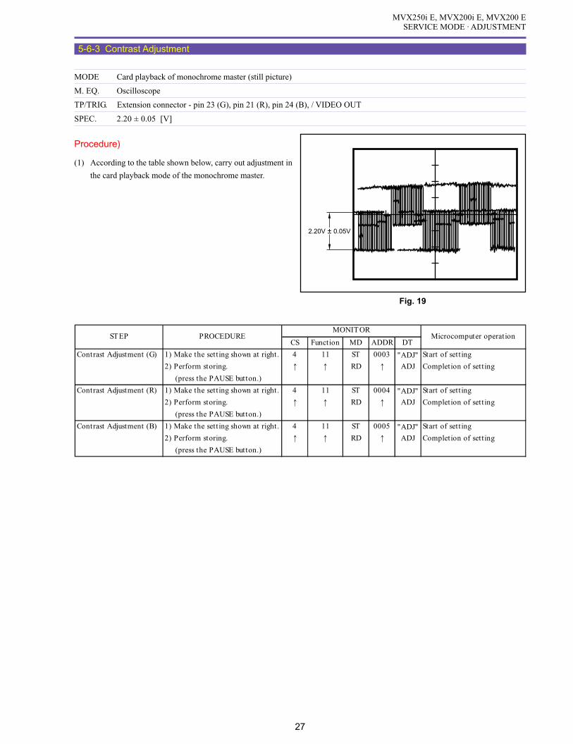
MVX250i E, MVX200i E, MVX200 ESERVICE MODE · ADJUSTMENT
27
5-6-3 Contrast Adjustment
MODE Card playback of monochrome master (still picture)
M. EQ. Oscilloscope
TP/TRIG. Extension connector - pin 23 (G), pin 21 (R), pin 24 (B), / VIDEO OUT
SPEC. 2.20 ± 0.05 [V]
Procedure)
(1) According to the table shown below, carry out adjustment in
the card playback mode of the monochrome master.
CS Function MD ADDR DT
Contrast Adjustment (G) 1) Make the setting shown at right. 4 11 ST 0003 "ADJ" Start of setting
2) Perform storing. ↑ ↑ RD ↑ ADJ Completion of setting
(press the PAUSE button.)
Contrast Adjustment (R) 1) Make the setting shown at right. 4 11 ST 0004 "ADJ" Start of setting
2) Perform storing. ↑ ↑ RD ↑ ADJ Completion of setting
(press the PAUSE button.)
Contrast Adjustment (B) 1) Make the setting shown at right. 4 11 ST 0005 "ADJ" Start of setting
2) Perform storing. ↑ ↑ RD ↑ ADJ Completion of setting
(press the PAUSE button.)
STEP PROCEDUREMONITOR
Microcomputer operation
Fig. 19
2.20V ± 0.05V

MVX250i E, MVX200i E, MVX200 ESERVICE MODE · ADJUSTMENT
28
5-6-4 Brightness Adjustment
MODE Card playback of monochrome master (still picture)
M. EQ. Oscilloscope
TP/TRIG. Extension connector - pin 23 (G), pin 21 (R), pin 24 (B), / VIDEO OUT
SPEC. 2.60 ± 0.05 [V]
Procedure)
(1) According to the table shown below, carry out adjustment in
the card playback mode of the monochrome master.
Fig. 20
2.60V ± 0.05V
CS Function MD ADDR DT
Brightness Adjustment (G) 1) Make the setting shown at right. 4 11 ST 0006 "ADJ" Start of setting
2) Perform storing. ↑ ↑ RD ↑ ADJ Completion of setting
(press the PAUSE button.)
Brightness Adjustment (R) 1) Make the setting shown at right. 4 11 ST 0007 "ADJ" Start of setting
2) Perform storing. ↑ ↑ RD ↑ ADJ Completion of setting
(press the PAUSE button.)
Brightness Adjustment (B) 1) Make the setting shown at right. 4 11 ST 0008 "ADJ" Start of setting
2) Perform storing. ↑ ↑ RD ↑ ADJ Completion of setting
(press the PAUSE button.)
STEP PROCEDUREMONITOR
Microcomputer operation

MVX250i E, MVX200i E, MVX200 ESERVICE MODE · ADJUSTMENT
29
5-6-5 Black Limiter Level Adjustment
MODE Card playback of monochrome master (still picture)
M. EQ. Oscilloscope
TP/TRIG. Extension connector - pin 23 (EVF G) / VIDEO OUT
SPEC. 4.45 ± 0.05 [V]
Procedure)
(1) According to the table shown below, carry out adjustment in
the card playback mode of the monochrome master.
Fig. 21
4.45V ± 0.05V
CS Function MD ADDR DT
Black Limiter Level 1) Make the setting shown at right. 4 11 RD 0006 Original value Record the original value.
Adjustment 1) Make the setting shown at right. 4 11 ST 0006 00 Setting of 00
2) Perform storing. ↑ ↑ RD ↑ ↑ (press the PAUSE button.)
3) Make the setting shown at right. 4 11 ST 0009 "ADJ" Start of setting
4) Perform storing. ↑ ↑ RD ↑ ADJ Completion of setting
(press the PAUSE button.)
5) Make the setting shown at right. 4 11 ST 0006 Original value Reset to the recorded
original value.
6) Perform storing. ↑ ↑ RD ↑ ↑ (press the PAUSE button.)
STEP PROCEDUREMONITOR
Microcomputer operation
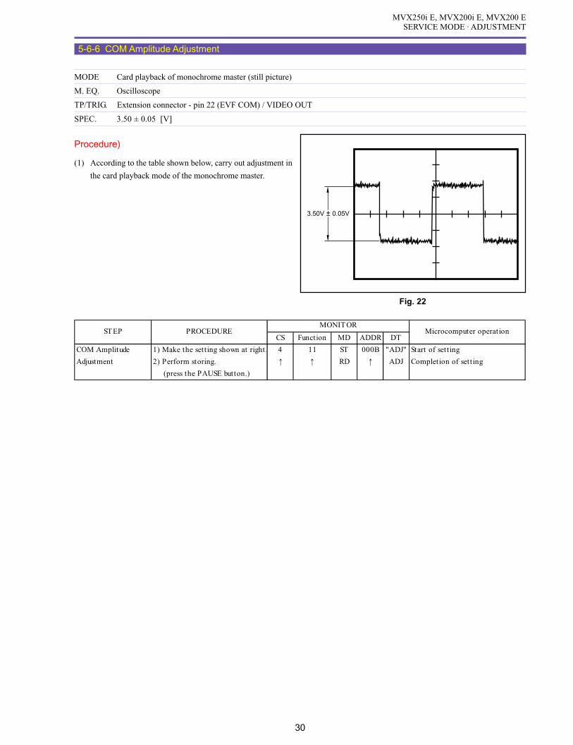
MVX250i E, MVX200i E, MVX200 ESERVICE MODE · ADJUSTMENT
30
5-6-6 COM Amplitude Adjustment
MODE Card playback of monochrome master (still picture)
M. EQ. Oscilloscope
TP/TRIG. Extension connector - pin 22 (EVF COM) / VIDEO OUT
SPEC. 3.50 ± 0.05 [V]
Procedure)
(1) According to the table shown below, carry out adjustment in
the card playback mode of the monochrome master.
CS Function MD ADDR DT
COM Amplitude 1) Make the setting shown at right. 4 11 ST 000B "ADJ" Start of setting
Adjustment 2) Perform storing. ↑ ↑ RD ↑ ADJ Completion of setting
(press the PAUSE button.)
STEP PROCEDUREMONITOR
Microcomputer operation
Fig. 22
3.50V ± 0.05V

MVX250i E, MVX200i E, MVX200 ESERVICE MODE · ADJUSTMENT
31
5-6-7 COM-DC Level Adjustment
MODE Card playback of monochrome master (still picture)
M. EQ. Oscilloscope
TP/TRIG. Extension connector - pin 22 (EVF COM) / VIDEO OUT
SPEC. 3.20 ± 0.05 [V] (DC. P-P center of EVF COM to GND level)
Procedure)
(1) According to the table shown below, carry out adjustment in
the card playback mode of the monochrome master.
Fig. 23
3.20V ± 0.05V
CS Function MD ADDR DT
COM-DC Level 1) Make the setting shown at right. 4 11 ST 000A "ADJ" Start of setting
Ajustment 2) Perform storing. ↑ ↑ RD ↑ ADJ Completion of setting
(press the PAUSE button.)
STEP PROCEDUREMONITOR
Microcomputer operation

MVX250i E, MVX200i E, MVX200 ESERVICE MODE · ADJUSTMENT
32
5-6-8 Flash Memory Writing
SPEC. Automatic Writing
Procedure)
(1) Write adjustment data (5-6-2 to 7) into the flash memory according the table shown below.
Procedure)
(1) Referring to the table shown below, Flash Memory writing.
5-6-9 Release of Forced CVF ON
Procedure)
(1) Referring to the table shown below, make the setting.
CS Function MD ADDR DT
Release of Forced 1) Make the setting shown at right. 1 10 ST 0017 00 Start of setting
CVF ON 2) Perform storing. ↑ ↑ RD ↑ Completion of setting
(press the PAUSE button.)
STEP PROCEDUREMONITOR
Microcomputer operation
CS Function MD ADDR DT
1 1) Make the setting shown at right. 4 09 ST 0081 00 Flash Memory Writing
2) Perform storing. ↑ ↑ RD ↑ (press the PAUSE button.)
STEP PROCEDUREMONITOR
Microcomputer operation

MVX250i E, MVX200i E, MVX200 ESERVICE MODE · ADJUSTMENT
33
5-7 Color Balance Check
Preparation)
(1) Carry out this correction in the product state.
(2) Adjustment Conditions
Program AE : AUTO
AF : OFF
Image stabilizer : OFF
Digital zoom : OFF
CHART Lightbox (5600°K), and color bar chart
M.EQ. Vectorscope
TP/TRIG. VIDEO OUT
SPEC. R : × 1.75 98° (± 0.15, ±5°), Ye : × 0.9 175° (± 0.15, ±5°)
Procedure)
(1) Quit the service mode, and turn power OFF/ON.
(2) Perform light-box recording, and carry out WB SET using the relevant function of the product.
(3) Take an image of the color bar chart, and check that the levels of R, Ye and G are within the specified ranges respectively.
(4) If the result of the above check is NG, carry out camera section adjustment again.

MVX250i E, MVX200i E, MVX200 ESERVICE MODE · ADJUSTMENT
34
5-8 Recorder Section Adjustment
Note)
(1) Each of the adjustment data (5-8-1 to 5-8-3) becomes valid when 5-8-5 flash memory writing is made. When turning power OFF/
ON during each adjustment, be sure to carry out 5-8-5 flash memory writing.
Preparation)
(1) Except for the tape-path adjustment, carry out adjustment in the product state.
5-8-0 LCD PCB Setting Destination
When mounting the LCD P.C.B of service part, perform the following adjustment.
5-8-1 SWP Adjustment
MODE Playback of color bar master (DY9-1381-000)
SPEC. Automatic adjustment
Procedure)
(1) While playing back the color bar master, carry out SWP automatic adjustment referring to the table shown below.
STEP PROCEDURE MONITOR Microcomputer operation
C.FG(AUTO) CS Function MD ADDR DT
1 1) Make the setting shown at right. 0 08 ST 0003 --
2) Perform storing. ↑ ↑ WR ↑ ↑ Automatic adjustment is in progress.
(press the PAUSE button.) RD Automatic adjustment is completed.
5-8-2 C. FG Adjustment
MODE Playback of color bar master (DY9-1381-000)
SPEC. Automatic adjustment
Procedure)
(1) While playing back the color bar master, carry out C.FG automatic adjustment referring to the table shown below.
STEP PROCEDURE MONITOR Microcomputer operation
SWP (AUTO) CS Function MD ADDR DT
1 1) Make the setting shown at right. 0 08 ST 0001 --
2) Perform storing. ↑ ↑ WR ↑ ↑ Automatic adjustment is in progress.
(press the PAUSE button.) RD Automatic adjustment is completed.
STEP PROCEDURE MONITOR Microcomputer operation
CS Function MD ADDR DT
1 1) Make the setting shown at right. 4 10 ST 0003 --
2) Add "09" to the current value, and
store the result data. RD ADJ
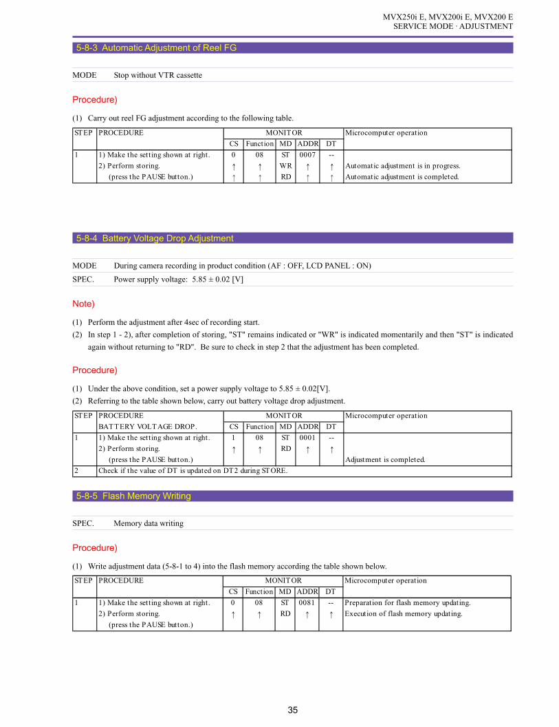
MVX250i E, MVX200i E, MVX200 ESERVICE MODE · ADJUSTMENT
35
5-8-3 Automatic Adjustment of Reel FG
MODE Stop without VTR cassette
Procedure)
(1) Carry out reel FG adjustment according to the following table.
STEP PROCEDURE MONITOR Microcomputer operation
CS Function MD ADDR DT
1 1) Make the setting shown at right. 0 08 ST 0007 --
2) Perform storing. ↑ ↑ WR ↑ ↑ Automatic adjustment is in progress.
(press the PAUSE button.) RD Automatic adjustment is completed.
5-8-4 Battery Voltage Drop Adjustment
MODE During camera recording in product condition (AF : OFF, LCD PANEL : ON)
SPEC. Power supply voltage: 5.85 ± 0.02 [V]
Note)
(1) Perform the adjustment after 4sec of recording start.
(2) In step 1 - 2), after completion of storing, "ST" remains indicated or "WR" is indicated momentarily and then "ST" is indicated
again without returning to "RD". Be sure to check in step 2 that the adjustment has been completed.
Procedure)
(1) Under the above condition, set a power supply voltage to 5.85 ± 0.02[V].
(2) Referring to the table shown below, carry out battery voltage drop adjustment.
5-8-5 Flash Memory Writing
SPEC. Memory data writing
Procedure)
(1) Write adjustment data (5-8-1 to 4) into the flash memory according the table shown below.
STEP PROCEDURE Microcomputer operation
CS Function MD ADDR DT
1 1) Make the setting shown at right. 0 08 ST 0081 -- Preparation for flash memory updating.
2) Perform storing. ↑ ↑ RD ↑ ↑ Execution of flash memory updating.
(press the PAUSE button.)
MONITOR
STEP PROCEDURE MONITOR Microcomputer operation
BATTERY VOLTAGE DROP. CS Function MD ADDR DT
1 1) Make the setting shown at right. 1 08 ST 0001 --
2) Perform storing. ↑ ↑ RD ↑ ↑ (press the PAUSE button.) Adjustment is completed.
2 Check if the value of DT is updated on DT2 during STORE.

MVX250i E, MVX200i E, MVX200 ESERVICE MODE · ADJUSTMENT
36
5-9 Tape Path Adjustment
Note)
(1) For tape path adjustment, the service mode setting is necessary. For the details of setting procedure, refer to the DMC III Section.
Preparation)
(1) For tape path adjustment, make the recorder adjustment setting (P. 2, 3).
Procedure)
(1) Referring to the table given below (STEPS 1, 2, 3), play back the tracking master (DY9-1345-000) for tape path adjustment.
At STEP 2, perform tracking shift by adjusting DT in a range of F0 to FF so that the RF envelope will be 70%.
(2) After adjustment, restore tracking shift setting to normal according to the following table (STEPS 4 : P.OFF).
STEP PROCEDURE Microcomputer operation
TRACKING TAPE CS Function MD ADDR DT
1 1) Play back the tracking tape.
2 1) Set up tracking shift .
2-1 1) Make the setting shown at right. 0 00 ST 9FE7 F2
2) Perform storing. ↑ ↑ RD ↑ ↑ (press the PAUSE button.)
3) Perform 70% tracking shift by ↑ ↑ ST ↑ F0~FF The amount of tracking shift is changed.
adjusting DT in a range of F0 to FF.
4) Perform storing. ↑ ↑ RD ↑ ↑ (press the PAUSE button.)
* Tracking shift released in DT00.
3 1) Perform tape path adjustment with the RF envelope in 70% tracking shift state.
4 1) Select the normal mode.
2) Turn off power to the main unit.
MONITOR

MVX250i E, MVX200i E, MVX200 ESERVICE MODE · ADJUSTMENT
37
R-Y
BURST
B-Y
PAL
R
Ye
Copy the chart on a transparent film. Trim and attach the transparent chart on a vectorscope display.
Color balance adjustment chartMVX250i E, MVX200 E, MV200i E
MVX250i E, MVX200 E, MV200i E
Color balance check chart
R-Y
R
Ye
BURST
B-Y
PAL

SERVICE HINTS
CONTENTS
1. Service Hints -------------------------------------------------------------------------------------------------------------------------------------- 1
1-1 Arrangement of Circuit Boards --------------------------------------------------------------------------------------------------------- 1
1-2 Location of Main Elements ------------------------------------------------------------------------------------------------------------- 2
1-3 Current Consumption Check ----------------------------------------------------------------------------------------------------------- 4
2. Trouble Shooting --------------------------------------------------------------------------------------------------------------------------------- 5
2-1 Power Supply ----------------------------------------------------------------------------------------------------------------------------- 5
2-2 Camera Picture Faulty ------------------------------------------------------------------------------------------------------------------- 6
2-3 Faulty of Playback Picture -------------------------------------------------------------------------------------------------------------- 7
2-4 Startup Window Setting ----------------------------------------------------------------------------------------------------------------- 8
2-5 Short cut demonstration mode ---------------------------------------------------------------------------------------------------------- 9

MVX250i E, MVX200i E, MVX200 ESERVICE HINTS
1
1. Service Hints
1-1 Arrangement of Circuit Boards
The printed circuit boards are arranged as shown below.
Fig. 1
OPERATION KEY
CVF P.C.B.
JACK1 P.C.B.
JACK2 P.C.B.
CCD P.C.B.
MAIN P.C.B.
LCD P.C.B.
CAV P.C.B.
R-KEY P.C.B.

MVX250i E, MVX200i E, MVX200 ESERVICE HINTS
2
1-2 Location of Main Elements
Fig. 2
IC2302SDRAM
IC1102SDRAM
IC1103DIGIC DV
IC2301VIC4
IC2000VRP2
MAIN P.C.B.
FU1810
FU3202
FU3201
FU3205
FU3203
IC3201DC/DC CONVERTER CONTROL
IC100MODE MI-COM
IC102BACKUP
IC300OPE AMP
IC301MOTOR DRIVE
IC1810CHARGE IC
IC1811OPE AMP
IC32034.7V REGULATOR
IC2300FLASH
IC1101SDRAM

MVX250i E, MVX200i E, MVX200 ESERVICE HINTS
3
Fig. 3
CAV P.C.B.
LCD P.C.B.
JACK1 P.C.B. CCD P.C.B.
IC10042.8V REGULATOR
IC1001INVERTER
IC1002TG/CDS/AGC/AD/V-DRIVER
IC801AUDIO INTERFACE
IC1501EVF DRIVER
IC1200LENS DRIVE
IC4201DC/DC CONVERTER CONTROL
IC901EEPROM
IC902LCD DRIVE
IC1602SENSOR GYRO
IC1601SENSOR GYRO
IC1070CCD

MVX250i E, MVX200i E, MVX200 ESERVICE HINTS
4
1-3 Current Consumption Check
The following table shows the specified value of current consumption in each status.
Measurement condition : Product status, camera auto mode(AF OFF), LCD ON (Approx. 0.1A each smaller in case of CVF)
Preset voltage : 7.4V
POWER SW MODE Current consumption (A)
CAMERA REC PAUSE 0.43
REC 0.47
VCR STOP 0.29
PLAY 0.37
POWER OFF 0.6 (mA)

MVX250i E, MVX200i E, MVX200 ESERVICE HINTS
5
2. Trouble ShootingTo detect the failure part for repair, if any, use the following hints and check points.
2-1 Power Supply
<Hints>
When the power source is attached, the unit enters the standby mode in the following sequences.
Main power is connected. → UNREG is supplied to the MAIN P.C.B. → MODE MI-COM starts up. → MODE MI-COM outputs VCR
ON “H” signal. → PWM driver starts up and turns on each power supply. → Establishes communication with the FR MI-COM. → FR
MI-COM initializes recorder mechanical chassis. → After initialized, the MODE MI-COM is brought into the standby status with the
VCR ON changed to VCR Low.
After that, the power supply is turned ON by the following procedures.
Power supply mode switch operation → After MODE MI-COM is accepted, VCR ON “H” is output. → The PWM driver is started to
turn on various power supplies. → The FR MI-COM is started to control the system.
<Check Points>
1) Key Inputs
Check the key inputs at Powe r Switch in the SERVICE mode.
2) Check of microcomputer-to-microcomputer communication
If the microcomputer-to-microcomputer communication line is normal, the version number of each microcomputer can be indi-
cated in the service mode. Otherwise, the communication line or microcomputer may be faulty.
3) Error in Mechanism (“SERVICE MODE · ADJUSTMENT” P. 9)
If any error is occurred by mechanism trouble at initializing, the error can be detected.
At this state, the power can be turned on, but the unit enters “ERROR STOP” state. In this case, check the error data in the
SERVICE mode.
4) VCR O N “H”, CAM ON “H” (control signal from MODE MI-COM) Outputs
Check the output of control signal.
5) Fuses on the POWER SUPPLY P.C.B.
Check the continuity of the fuses FU3201, 3202, 3203, 3205 and 1801 on the MAIN P.C.B. In case of NG, replace the fuse and
check the power consumption.
6) Replace the MAIN P.C.B. with a service part and check the operation.
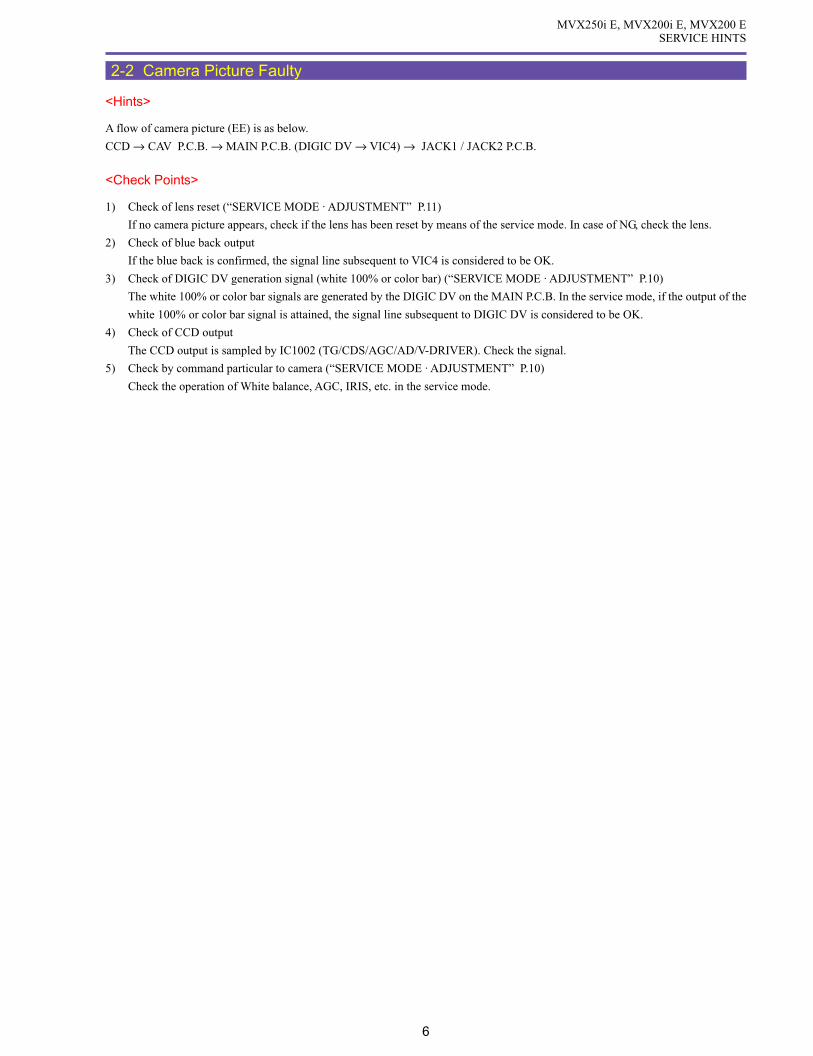
MVX250i E, MVX200i E, MVX200 ESERVICE HINTS
6
2-2 Camera Picture Faulty
<Hints>
A flow of camera picture (EE) is as below.
CCD → CAV P.C.B. → MAIN P.C.B. (DIGIC DV → VIC4) → JACK1 / JACK2 P.C.B.
<Check Points>
1) Check of lens reset (“SERVICE MODE · ADJUSTMENT” P.11)
If no camera picture appears, check if the lens has been reset by means of the service mode. In case of NG, check the lens.
2) Check of blue back output
If the blue back is confirmed, the signal line subsequent to VIC4 is considered to be OK.
3) Check of DIGIC DV generation signal (white 100% or color bar) (“SERVICE MODE · ADJUSTMENT” P.10)
The white 100% or color bar signals are generated by the DIGIC DV on the MAIN P.C.B. In the service mode, if the output of the
white 100% or color bar signal is attained, the signal line subsequent to DIGIC DV is considered to be OK.
4) Check of CCD output
The CCD output is sampled by IC1002 (TG/CDS/AGC/AD/V-DRIVER). Check the signal.
5) Check by command particular to camera (“SERVICE MODE · ADJUSTMENT” P.10)
Check the operation of White balance, AGC, IRIS, etc. in the service mode.

MVX250i E, MVX200i E, MVX200 ESERVICE HINTS
7
2-3 Faulty of Playback Picture
<Hints>
In the DV, degradation of picture quality normally appears on the screen as block noise. This is because, if an error occurs exceeding the
ability of the error correction circuit, the block by block information of pictures is not played back properly and thus complemented by
the previous picture information. Normally, such block noise appears on the screen when the error rate has considerably been degraded
due to the degraded tape or the lowered head output, etc. Be sure to check the playback picture quality by the error rate.
<Check Points>
1) Deterioration of Tape Quality
Check if flaws, kinks, etc. are found on a magnetic face of tape or not, and compare it with the error rate of other unit.
2) Error Rate (“SERVICE MODE · ADJUSTMENT” P. 8)
In the service mode, check an error rate of self-recording/LP playback. The specified allowable error rate is 2 × 10⁻⁵.
In case of NG, take the following procedure.
(1) Observe a playback envelope. If it is abnormal, carry out tape-path adjustment.
(2) Run a cleaning tape.
Use the cleaning tape of hard type (DY9-1384-000).
[Playback time]
After replacement of the drum unit → 25 seconds
For cleaning → 25 seconds per time
* Do not proceed to a playback for 25 seconds or more continuously.
* Limit the total of playback time to five minutes.
* When using hard-type cleaning tape, select the cleaning mode on the product main unit.
(Refer to “SERVICE MODE · ADJUSTMENT” [4-3 - Cleaning Mode] P.10)
(3) Check the error rate again.
If the error rate is out of the specified range, clean the tape drive parts (posts, drum) using cleaning paper moistened with
alcohol.
* Take care not to damage the head.
* Do not touch the head with bare hand.
(4) Check the error rate again.
If the error rate is out of the specified range, replace the tape with a new one and check the error rate again. At this step, use a
tape (must be Panasonic LP tape) which has been purchased at a different time. The error rate may become worse due to
inconsistent quality or aging of the tape.
(5) Check the error rate again.
If the error rate is out of the specified range, replace the drum unit.
(6) Check the error rate again.
If the error rate is out of the specified range, replace the mechanical unit.
MVX250i E, MVX200i E, MVX200 ESERVICE HINTS
8
2-4 Startup Window Setting
When user’s original data are written over the initial default data of the start-up image or the sound, shutter, operation or self-timer
[User Setting] , the user’s original data become a default data (replace the initial default data) after replacement of the MAIN P.C.B.
Note that the data thus written by the user is recognized as a non-original data. To avoid this, follow the next procedure.
Procedure)
How to save an original data to a PC and write it to the main unit:
(1) In the MyCamera window on the Zoom Browser EX, save original image data to a PC.
(2) Replace the MAIN P.C.B.
(3) In the MyCamera window, set the original image data saved at step (1) to the camera.
For details, refer to the DIGITAL VIDEO SOFTWARE INSTRUCTION MANUAL - “Customizing Your Camcorder with
the MyCamera Settings”.
Note)
Only where the USB I/F is available for connection between the PC and main unit, it is allowed to save/write original data using the
Zoom Browser EX.

MVX250i E, MVX200i E, MVX200 ESERVICE HINTS
9
2-5 Short cut demonstration mode
As a function destined to shop salesman, the Image stabilizer and white LED can easily be turned ON/OFF. Also, the screen
indicates the version of firmware.
<Operation procedure>
1. Start the operation in the camera mode or card camera mode, and take out the cassette and memory card.
2. Set the Program selector to “ P ”.
3. While holding down the Select/Set button, press the MENU button for at least two seconds with the P.AE mode selection screen
(Fig. 4) displayed. Release the MENU button only.
4. Releasing the MENU button displays the short cut demonstration screen (Fig. 5).
5. Operate the Selector dial to change different settings.
Note : The magenta indication items cannot be selected.
ex) IS setting in card camera mode.
6. Press the MENU button or select “CLOSE” on the screen to exit.
Fig. 4
P.AE mode selection screen
Fig. 5
Short cut demonstration screen

PARTS LIST
CONTENTS
EXPLODED VIEWS
Casing Parts Section --------------------------------------------------------------------------------------------------------------------------- 2
Front Cover Unit Section --------------------------------------------------------------------------------------------------------------------- 4
Left Cover Unit Section ----------------------------------------------------------------------------------------------------------------------- 6
Right Cover Unit Section --------------------------------------------------------------------------------------------------------------------- 8
LCD Unit Section ---------------------------------------------------------------------------------------------------------------------------- 10
Rear Cover Unit Section -------------------------------------------------------------------------------------------------------------------- 12
Recorder Unit Section-1 -------------------------------------------------------------------------------------------------------------------- 14
Recorder Unit Section-2 -------------------------------------------------------------------------------------------------------------------- 16
CVF Unit Section ---------------------------------------------------------------------------------------------------------------------------- 18
Camera Unit Section ------------------------------------------------------------------------------------------------------------------------ 20
Lens Unit Section ---------------------------------------------------------------------------------------------------------------------------- 22
Mechanical Chassis Section-1 ------------------------------------------------------------------------------------------------------------- 24
Mechanical Chassis Section-2 ------------------------------------------------------------------------------------------------------------- 26
Mechanical Chassis Section-3 ------------------------------------------------------------------------------------------------------------- 28
Mechanical Chassis Section-4 ------------------------------------------------------------------------------------------------------------- 30
Accessory Section-1 ------------------------------------------------------------------------------------------------------------------------- 32
Accessory Section-2 ------------------------------------------------------------------------------------------------------------------------- 34
FUSE Replacement Instruction ------------------------------------------------------------------------------------------------------------------ 36
ELECTRICAL PARTS LIST -------------------------------------------------------------------------------------------------------------------- 37
PARTS LIST --------------------------------------------------------------------------------------------------------------------------------------- 38

1
1. Especially critical parts in the power circuit block should not be replaced with other marks.
Critical parts are marked with in this electrical parts list.
2. For continued protection against risk of fire, replace FU3201, FU3202, FU3205 only with same TYPE
: 0435001 1.0-24V FUSE Replace FU3203, FU1810 only with same TYPE : 043501.5 1.5-24V FUSE
Manufacturer : Littel FUSE
CAUTION

2
MVX250i E, MVX200i E, MVX200 EPARTS LIST
Casing Parts Section
Rear Cover Unit
Left Cover Unit
Rigt Cover/LCD UnitFront Cover Unit
Camera/Lens/CVF/Recorder Unit
9×2
14
6×3
5
15
11
9
12
13
1111×3
611
6×3
9
12
10
4
3
2
1×4
7
8
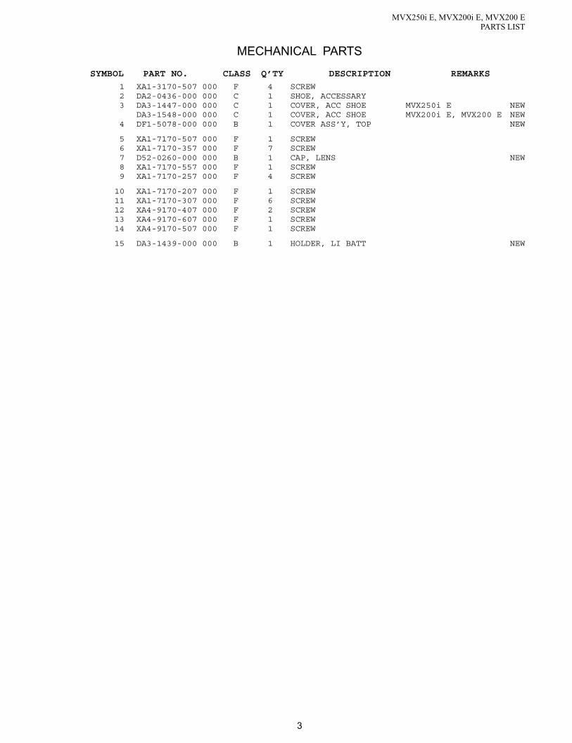
3
MECHANICAL PARTS
SYMBOL PART NO. CLASS Q’TY DESCRIPTION REMARKS
MVX250i E, MVX200i E, MVX200 EPARTS LIST
1 XA1-3170-507 000 F 4 SCREW2 DA2-0436-000 000 C 1 SHOE, ACCESSARY3 DA3-1447-000 000 C 1 COVER, ACC SHOE MVX250i E NEW
DA3-1548-000 000 C 1 COVER, ACC SHOE MVX200i E, MVX200 E NEW4 DF1-5078-000 000 B 1 COVER ASS’Y, TOP NEW
5 XA1-7170-507 000 F 1 SCREW6 XA1-7170-357 000 F 7 SCREW7 D52-0260-000 000 B 1 CAP, LENS NEW8 XA1-7170-557 000 F 1 SCREW9 XA1-7170-257 000 F 4 SCREW
10 XA1-7170-207 000 F 1 SCREW11 XA1-7170-307 000 F 6 SCREW12 XA4-9170-407 000 F 2 SCREW13 XA4-9170-607 000 F 1 SCREW14 XA4-9170-507 000 F 1 SCREW
15 DA3-1439-000 000 B 1 HOLDER, LI BATT NEW

4
MVX250i E, MVX200i E, MVX200 EPARTS LIST
Front Cover Unit Section
11×3
11×3
9
12
14
1311
10
20
19
184
76
58
1716
15
21
3
2
1
*1
*1 : MVX250i E ONLY
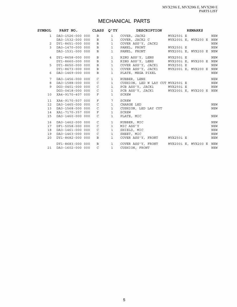
5
MECHANICAL PARTS
SYMBOL PART NO. CLASS Q’TY DESCRIPTION REMARKS
MVX250i E, MVX200i E, MVX200 EPARTS LIST
1 DA3-1526-000 000 B 1 COVER, JACK2 MVX250i E NEWDA3-1532-000 000 B 1 COVER, JACK2 C MVX200i E, MVX200 E NEW
2 DY1-8651-000 000 B 1 COVER ASS’Y, JACK2 NEW3 DA3-1470-000 000 B 1 PANEL, FRONT MVX250i E NEW
DA3-1531-000 000 B 1 PANEL, FRONT MVX200i E, MVX200 E NEW
4 DY1-8658-000 000 B 1 RING ASS’Y, LENS MVX250i E NEWDY1-8660-000 000 B 1 RING ASS’Y, LENS MVX200i E, MVX200 E NEW
5 DY1-8650-000 000 B 1 COVER ASS’Y, JACK1 MVX250i E NEWDY1-8673-000 000 B 1 COVER ASS’Y, JACK1 MVX200i E, MVX200 E NEW
6 DA3-1469-000 000 B 1 PLATE, MEGA PIXEL NEW
7 DA3-1456-000 000 C 1 RUBBER, LENS NEW8 DA3-1588-000 000 C 1 CUSHION, LED W LAY CUT MVX250i E NEW9 DG3-0401-000 000 C 1 PCB ASS’Y, JACK1 MVX250i E NEW
DG3-0418-000 000 C 1 PCB ASS’Y, JACK1 MVX200i E, MVX200 E NEW10 XA4-9170-407 000 F 1 SCREW
11 XA4-9170-507 000 F 7 SCREW12 DA3-1465-000 000 C 1 CHARGE LED NEW13 DA3-1568-000 000 C 1 CUSHION, LED LAY CUT NEW14 XA1-7170-357 000 F 1 SCREW15 DA3-1460-000 000 C 1 PLATE, MIC NEW
16 DA3-1462-000 000 C 1 RUBBER, MIC NEW17 DF1-5058-000 000 C 1 MIC ASS’Y NEW18 DA3-1461-000 000 C 1 SHIELD, MIC NEW19 DA3-1463-000 000 C 1 SHEET, MIC NEW20 DY1-8682-000 000 B 1 COVER ASS’Y, FRONT MVX250i E NEW
DY1-8683-000 000 B 1 COVER ASS’Y, FRONT MVX200i E, MVX200 E NEW21 DA3-1602-000 000 C 1 CUSHION, FRONT NEW

6
MVX250i E, MVX200i E, MVX200 EPARTS LIST
Left Cover Unit Section
1×21×2
9
10
12
18
16
24
1
22
23
15
17
13
14
16
54
2
3
7
8
19
23×4
21
11
20
25

7
MECHANICAL PARTS
SYMBOL PART NO. CLASS Q’TY DESCRIPTION REMARKS
MVX250i E, MVX200i E, MVX200 EPARTS LIST
1 XA1-7170-307 000 F 6 SCREW2 DA3-1472-000 000 B 1 COVER, CASSETE NEW3 WR1-5090-000 000 C 1 SPEAKER4 DA3-1489-000 000 C 1 CUSHION, SPEAKER NEW5 DH2-5206-000 000 C 1 FPC, SPEAKER NEW
6 DA3-1485-000 000 B 1 COVER, REGULATION NEW7 DA3-1593-000 000 C 1 TAPE, GND NEW8 DA3-1484-000 000 C 1 HOOK, F GRIP NEW9 DA3-1486-000 000 B 1 COVER, ZOOM TOP NEW
10 DA3-1488-000 000 B 1 TAPE, ZOOM TOP COVER NEW
11 DA3-1592-000 000 C 1 TAPE, ZOOM TOP COVER2 NEW12 DG3-0408-000 000 B 1 ZOOM PHOTO ASS’Y MVX250i E NEW
DG3-0432-000 000 B 1 ZOOM PHOTO ASS’Y MVX200i E, MVX200 E NEW13 DA3-1471-000 000 B 1 COVER, LEFT NEW14 DA3-1601-000 000 C 1 TAPE,LB GND NEW
15 DA3-1483-000 000 C 1 LOCK, GRIP PIN NEW16 DA3-1482-000 000 C 1 KNOB, CASSETTE OPEN NEW17 DA3-1481-000 000 C 1 SPRING, CASSETTE HOOK NEW18 DA3-1477-000 000 C 1 SPRING, CASSETTE CLICK NEW19 DA3-1603-000 000 C 1 CUSHION, L COVER NEW
20 XA1-7170-357 000 F 1 SCREW21 DF1-5064-000 000 C 1 ARM ASS’Y, CASSETTE NEW22 DA3-1574-000 000 C 1 SHIELD, LEFT COVER NEW23 XA4-9170-459 000 F 5 SCREW24 DA3-1487-000 000 C 1 SHEET, CASSETTE ARM NEW
25 DA3-1595-000 000 C 1 LABEL, CAUTION MVX250i E NEWDA3-1597-000 000 C 1 LABEL, CAUTION MVX200i E NEWDA3-1596-000 000 C 1 LABEL, CAUTION MVX200 E NEW

8
MVX250i E, MVX200i E, MVX200 EPARTS LIST
Right Cover Unit Section
LCD UNIT
1×2
4
2
7
1
3
1
5
11
98
13
12
10
6
A
A
14
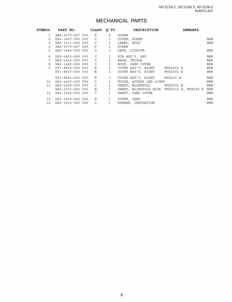
9
MECHANICAL PARTS
SYMBOL PART NO. CLASS Q’TY DESCRIPTION REMARKS
MVX250i E, MVX200i E, MVX200 EPARTS LIST
1 XA4-9170-507 000 F 4 SCREW2 DA3-1437-000 000 C 1 COVER, HINGE NEW3 DA3-1611-000 000 C 1 LABEL, HOLD NEW4 XA4-9170-407 000 F 1 SCREW5 DA3-1440-000 000 C 1 CASE, LITHIUM NEW
6 DG3-0403-000 000 C 1 PCB ASS’Y, KEY NEW7 DA3-1443-000 000 C 1 BASE, TRIPOD NEW8 DA3-1445-000 000 C 1 HOOK, CARD COVER NEW9 DY1-8656-000 000 B 1 COVER ASS’Y, RIGHT MVX250i E NEW
DY1-8657-000 000 B 1 COVER ASS’Y, RIGHT MVX200i E NEW
DY1-8681-000 000 B 1 COVER ASS’Y, RIGHT MVX200 E NEW10 DA3-1435-000 000 C 1 GUIDE, ACCESS LED LIGHT NEW11 DA3-1438-000 000 C 1 SHEET, BLINDFOLD MVX250i E NEW
DA3-1571-000 000 B 1 SHEET, BLINDFOLD BLUE MVX200i E, MVX200 E NEW12 DA3-1442-000 000 C 1 SHAFT, CARD COVER NEW
13 DA3-1436-000 000 B 1 COVER, CARD NEW14 DA3-1610-000 000 C 1 RUBBER, INSULATION NEW

10
MVX250i E, MVX200i E, MVX200 EPARTS LIST
LCD Unit Section
5×4
1×2
2
3
6
7
8
9
10
11
18
12
14
13
15 16 17
4

11
MECHANICAL PARTS
SYMBOL PART NO. CLASS Q’TY DESCRIPTION REMARKS
MVX250i E, MVX200i E, MVX200 EPARTS LIST
1 XA1-7170-407 000 F 2 SCREW2 DA3-1508-000 000 B 1 COVER, LCD TOP MVX250i E NEW
DA3-1552-000 000 B 1 COVER, LCD TOP MVX200i E NEWDA3-1534-000 000 B 1 COVER, LCD TOP MVX200 E NEW
3 DG3-0400-000 000 C 1 PCB ASS’Y, LCD NEW
4 DA3-1503-000 000 C 1 HOLDER, LCD NEW5 DA3-1607-000 000 C 4 SHEET, LCD2 NEW6 DG3-0404-000 000 C 1 BACK LIGHT ASS’Y, LCD NEW
*1 7 DY1-8670-000 000 B 1 LCD ASS’Y(SELECTION) NEW*2 WG2-5272-000 000 B 1 LCD ASS’Y NEW
8 DA3-1502-000 000 B 1 COVER, LCD BOTTOM MVX250i E NEWDA3-1510-000 000 B 1 COVER, LCD BOTTOM MVX200i E, MVX200 E NEW
9 DA3-1569-000 000 C 1 SPRING, LCD LOCK NEW10 DA3-1506-000 000 B 1 KNOB, LCD OPEN NEW11 DA2-0909-000 000 C 1 SHAFT, LCD LOCK
12 DA3-1504-000 000 B 1 COVER, LCD HINGE TOP MVX250i E NEWDA3-1544-000 000 B 1 COVER, LCD HINGE TOP MVX200i E, MVX200 E NEW
13 DA2-1737-000 000 1 MAGNET, HINJI14 DG3-0406-000 000 C 1 HINGE, LCD NEW15 DH2-5205-000 000 C 1 FPC, LCD-KEY NEW
16 DA3-1505-000 000 B 1 COVER, LCD HINGE BOTTOM NEW17 XA4-9170-907 000 F 1 SCREW NEW18 DG3-0419-000 000 C 1 FPC, LCD DETECT NEW
*1 : Free from the pixel dot.
*2 : Same quality as the production line.

12
MVX250i E, MVX200i E, MVX200 EPARTS LIST
Rear Cover Unit Section
13×3
3×2
1
6
5
4
2
3
7
3
1112
38
910
14
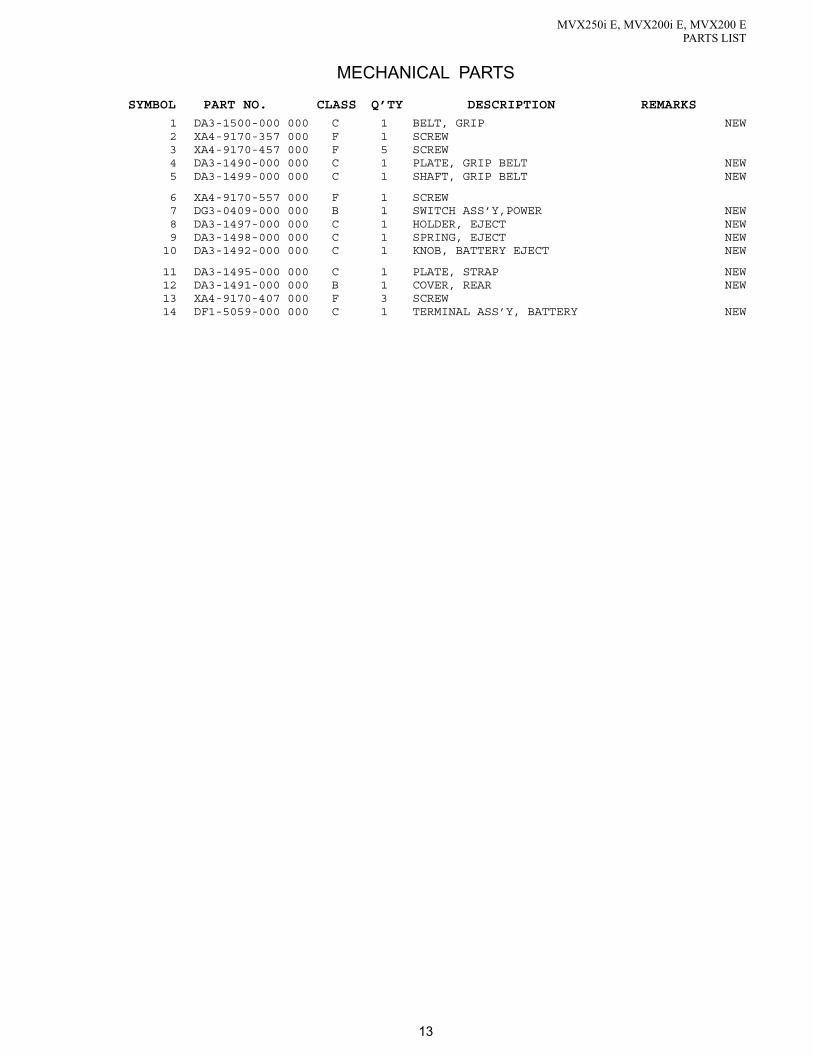
13
MECHANICAL PARTS
SYMBOL PART NO. CLASS Q’TY DESCRIPTION REMARKS
MVX250i E, MVX200i E, MVX200 EPARTS LIST
1 DA3-1500-000 000 C 1 BELT, GRIP NEW2 XA4-9170-357 000 F 1 SCREW3 XA4-9170-457 000 F 5 SCREW4 DA3-1490-000 000 C 1 PLATE, GRIP BELT NEW5 DA3-1499-000 000 C 1 SHAFT, GRIP BELT NEW
6 XA4-9170-557 000 F 1 SCREW7 DG3-0409-000 000 B 1 SWITCH ASS’Y,POWER NEW8 DA3-1497-000 000 C 1 HOLDER, EJECT NEW9 DA3-1498-000 000 C 1 SPRING, EJECT NEW
10 DA3-1492-000 000 C 1 KNOB, BATTERY EJECT NEW
11 DA3-1495-000 000 C 1 PLATE, STRAP NEW12 DA3-1491-000 000 B 1 COVER, REAR NEW13 XA4-9170-407 000 F 3 SCREW14 DF1-5059-000 000 C 1 TERMINAL ASS’Y, BATTERY NEW

14
MVX250i E, MVX200i E, MVX200 EPARTS LIST
Recorder Unit Section-1
A
A1
2 34
6
54
7
7
Camera/Lens/Recorder Unit
CVF Unit
4 *1
*1
*1 : MVX250i E ONLY

15
MECHANICAL PARTS
SYMBOL PART NO. CLASS Q’TY DESCRIPTION REMARKS
MVX250i E, MVX200i E, MVX200 EPARTS LIST
1 DH2-5175-000 000 C 1 FPC, ACS-MAIN MVX250i E NEW2 DG3-0410-000 000 C 1 CONNECTOR ASS’Y, SHOE MVX250i E NEW3 XA1-7170-357 000 F 1 SCREW4 XA1-7170-257 000 F 3 SCREW5 DA3-1604-000 000 C 1 CUSHION, RC1 NEW
6 DA3-1605-000 000 C 1 CUSHION, RC2 NEW7 XA1-7170-207 000 F 2 SCREW

16
MVX250i E, MVX200i E, MVX200 EPARTS LIST
Recorder Unit Section-2Camera/Lens Unit
A
A
9×38
7×32×3
4×2
5×2
2×2
12
15
16
13
22
21
17
18
20
19
23
14
10
5
3
1
4
24
11
6

17
MECHANICAL PARTS
SYMBOL PART NO. CLASS Q’TY DESCRIPTION REMARKS
MVX250i E, MVX200i E, MVX200 EPARTS LIST
<Caution> 1 DY1-8609-000 000 C 1 RECORDER UNIT, DMCIII2 XA1-7170-257 000 F 5 SCREW3 DG3-0402-000 000 C 1 PCB ASS’Y, JACK2 NEW4 DA3-1026-000 000 F 3 SCREW5 DA3-1429-000 000 C 3 RUBBER, HOLDER NEW
6 DF1-5075-000 000 C 1 HOLDER, RECORDER NEW7 XA9-1167-000 000 F 3 SCREW8 DA2-0314-000 000 C 1 SPRING, PLATE9 DA3-0941-000 000 C 3 RUBBER, INSULATION
10 DA3-1426-000 000 C 1 HOLDER, SUB NEW
11 DA3-1591-000 000 C 1 RUBBER, SHIELDING FOAM NEW12 DA3-0161-000 000 C 1 SHIELD CASE, HA13 DA3-1428-000 000 C 1 SHIELD CASE, PM2 NEW14 DA3-1609-000 000 C 1 CUSHION, CCD CORE NEW15 DH2-5174-000 000 C 1 FPC, MAIN-JACK2 NEW
16 DH2-5173-000 000 C 1 FPC, MAIN-JACK1 NEW17 WE8-6147-000 000 C 1 CORE, FERRITE NEW18 DH2-5204-000 000 C 1 FPC, CAV-JACK1 NEW19 DH2-5209-000 000 C 1 CABLE, MAIN-JACK1 NEW20 DG3-0398-000 000 C 1 PCB ASS’Y, CAV NEW
21 DH2-5172-000 000 C 1 FPC, MAIN-KEY NEW22 DA3-1427-000 000 C 1 SHIELD CASE, PM1 NEW23 DY1-8645-000 000 C 1 PCB ASS’Y, MAIN MVX250i E NEW
DY1-8648-000 000 C 1 PCB ASS’Y, MAIN MVX200i E NEWDY1-8649-000 000 C 1 PCB ASS’Y, MAIN MVX200 E NEW
24 XA1-7170-207 000 F 1 SCREW
<Caution> : When using this part on the product, replace the Housing Cover with the
DA3-2345-000 (Symbol No.10, page 25).
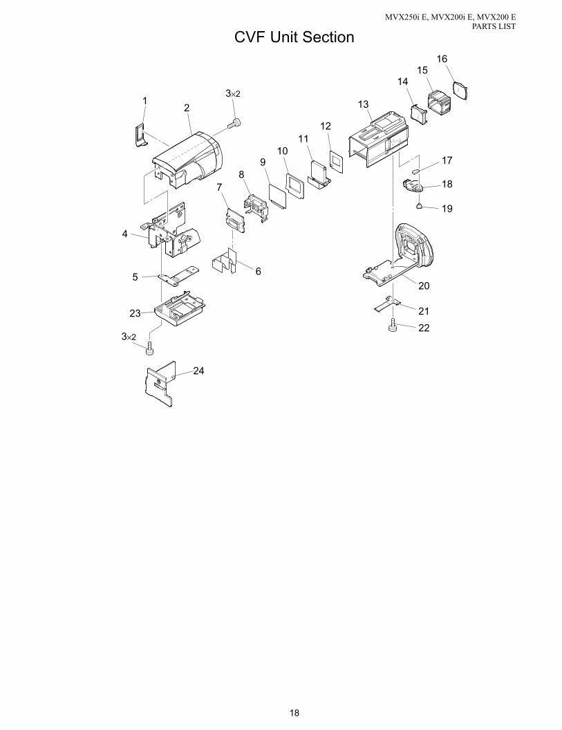
18
MVX250i E, MVX200i E, MVX200 EPARTS LIST
CVF Unit Section
3×2
3×2
12
7
4
65
23
24
89
1011
12
13
17
18
19
21
22
1415
16
20

19
MECHANICAL PARTS
SYMBOL PART NO. CLASS Q’TY DESCRIPTION REMARKS
MVX250i E, MVX200i E, MVX200 EPARTS LIST
1 DA3-1517-000 000 B 1 COVER, DUST NEW2 DA3-1511-000 000 B 1 COVER, CVF TOP NEW3 XA1-7170-257 000 F 4 SCREW4 DG3-0407-000 000 C 1 HINGE ASS’Y, CVF NEW5 DA3-1518-000 000 C 1 PLATE, CVF CLICK NEW
6 DH2-5203-000 000 C 1 FPC, CVF-CAV NEW7 DG3-0405-000 000 C 1 PCB ASS’Y, CVF NEW8 DA3-1521-000 000 C 1 REFLECTOR, CVF NEW9 DA3-1523-000 000 C 1 DIFFUSER, CVF NEW
10 DA3-1522-000 000 C 1 CUSHION, CVF PANEL NEW
11 WG2-5241-000 000 C 1 LCD ASS’Y, CVF12 DA3-2318-000 000 C 1 MASK, CVF NEW13 DY1-8678-000 000 B 1 COVER ASS’Y, CVF INNER TOP NEW14 YN1-3090-000 000 C 1 LENS, EYEPIECE 1 NEW15 DA3-1516-000 000 C 1 HOLDER, CVF LENS NEW
16 YN1-3093-000 000 C 1 LENS, EYEPIECE 2 NEW17 DA3-1076-000 000 C 1 RUBBER, CVF KNOB18 DA3-1520-000 000 C 1 KNOB, CVF NEW19 XA9-1166-000 000 F 1 SCREW20 DY1-8703-000 000 B 1 COVER ASS’Y, CVF INNER BOTTOM NEW
21 DA3-1071-000 000 C 1 SPRING, CVF CLICK22 XA4-9170-407 000 F 1 SCREW23 DA3-1512-000 000 B 1 COVER, CVF BOTTOM NEW24 DA3-1524-000 000 C 1 HOLDER, FPC NEW

20
MVX250i E, MVX200i E, MVX200 EPARTS LIST
Camera Unit Section
LENS UNIT
6×2
1
2
7
4
3
5

21
MECHANICAL PARTS
SYMBOL PART NO. CLASS Q’TY DESCRIPTION REMARKS
MVX250i E, MVX200i E, MVX200 EPARTS LIST
1 DH9-3009-000 000 B 1 FILTER, IR NEW2 DA3-1424-000 000 C 1 RUBBER, INSULATION NEW3 DY1-8671-000 000 C 1 CCD ASS’Y NEW4 DH2-5176-000 000 C 1 FPC, CCD-CAV NEW5 DG3-0399-000 000 C 1 PCB ASS’Y, CCD NEW
6 XA4-9170-507 000 F 2 SCREW7 WE8-6201-000 000 C 1 CORE, FERRITE NEW

22
MVX250i E, MVX200i E, MVX200 EPARTS LIST
Lens Unit Section
2×2
4×2
5
2
3
3
1

23
MECHANICAL PARTS
SYMBOL PART NO. CLASS Q’TY DESCRIPTION REMARKS
MVX250i E, MVX200i E, MVX200 EPARTS LIST
1 DG3-0715-000 000 C 1 LENS ASS’Y NEW2 XA4-9170-457 000 F 3 SCREW NEW3 XA4-9170-357 000 F 2 SCREW4 XA4-5170-457 000 F 2 SCREW5 YH8-2015-000 000 C 1 IG METER ASS’Y NEW

24
DMC IIIPARTS LIST
1
(10)
3
9
5
7
8
6
4
2
3×3
Mechanical Chassis Section-1

25
MECHANICAL PARTS
SYMBOL PART NO. CLASS Q’TY DESCRIPTION REMARKS
DMC IIIPARTS LIST
<Caution> 1 DG1-4506-000 000 B 1 COMPARTMENT ASS’Y, CASSETTE2 XA1-7140-147 000 C 1 SCREW3 DA2-2138-000 000 C 4 SCREW4 DY1-8500-000 000 E 1 DRUM ASS’Y NEW5 DA2-2139-000 000 C 1 WASHER
6 DF1-1703-000 000 C 1 IDLER ASS’Y7 DA2-2116-000 000 C 1 SPRING, COIL (DRUM)8 DA2-2115-000 000 C 1 SCREW9 DY1-8501-000 000 B 1 CHASSIS ASS’Y, SLIDE
10 DA3-2345-000 000 C 1 COVER, HOUSING NEW
<Caution> : When using this part on the product, replace the Housing Cover with the
DA3-2345-000 (Symbol No.10).

26
DMC IIIPARTS LIST
123
4
5
6
7
8
6
1
9
10
13
11
12
Mechanical Chassis Section-2

27
MECHANICAL PARTS
SYMBOL PART NO. CLASS Q’TY DESCRIPTION REMARKS
DMC IIIPARTS LIST
1 DA2-0645-000 000 C 2 WASHER2 DG1-4504-000 000 C 1 REEL ASS’Y, S3 DS1-0193-000 000 C 1 SPRING, COIL (TENSION)4 DF1-1693-000 000 C 1 BRAKE ASS’Y, TENSION5 DF1-1694-000 000 C 1 RELEASE ASS’Y, TENSION
6 DA2-2139-000 000 C 2 WASHER7 DF1-1704-000 000 C 1 BRAKE ASS’Y, S8 DS1-0199-000 000 C 1 SPRING, COIL (S BRAKE)9 DG1-4505-000 000 C 1 REEL ASS’Y, T
10 DA2-2220-000 000 C 1 LEVER, EJECT
11 DA2-2238-000 000 C 1 BRAKE, MAIN T12 DS1-0198-000 000 C 1 SPRING, COIL (T BRAKE)13 DF1-1695-000 000 C 1 REVIEW ARM ASS’Y

28
DMC IIIPARTS LIST
2×2
2×2
2×3
38
9
210
11
12
13
(4)
(6)
(14)
(7)
(5)1
Mechanical Chassis Section-3

29
MECHANICAL PARTS
SYMBOL PART NO. CLASS Q’TY DESCRIPTION REMARKS
DMC IIIPARTS LIST
1 DG1-4502-000 000 C 1 MOTOR ASS’Y, LOADING2 DA2-2261-000 000 C 8 SCREW3 DG1-4497-010 000 C 1 GUIDE RAIL ASS’Y4 DF1-1687-000 000 C 1 ROLLER ASS’Y, GUIDE S5 DF1-1688-000 000 C 1 ROLLER ASS’Y, GUIDE T
6 DA2-0780-000 000 C 1 SCREW7 DF1-1686-000 000 C 1 DRUM BASE ASS’Y8 DA2-2259-000 000 C 1 SCREW9 DG1-4503-000 000 C 1 MOTOR ASS’Y, CAPSTAN
10 XA1-7140-147 000 C 1 SCREW
11 DG1-4500-000 000 C 1 ROLLER ASS’Y, PINCH12 DA2-2139-000 000 C 1 WASHER13 DS1-0192-000 000 C 1 SPRING, COIL (PINCH)14 DA2-2128-000 000 C 1 S LOADING GEAR

30
DMC IIIPARTS LIST
1
3
4
5
8
9
6
10
7
2
11
Mechanical Chassis Section-4

31
MECHANICAL PARTS
SYMBOL PART NO. CLASS Q’TY DESCRIPTION REMARKS
DMC IIIPARTS LIST
1 DA2-2191-000 000 C 1 LEVER, CAM2 XA1-7140-147 000 C 1 SCREW3 DA2-2196-000 000 C 1 BELT, TIMING4 DA2-2197-000 000 C 1 GEAR, PULLEY5 DA2-2190-000 000 C 1 GEAR, CONNECT
6 DA2-2140-000 000 C 1 WASHER7 DA2-2188-000 000 C 1 GEAR, WHEEL8 DA2-2139-000 000 C 1 WASHER9 DA2-2195-000 000 C 1 GEAR, CAPSTAN
10 DG1-4501-000 000 C 1 CHASSIS ASS’Y, MAIN
11 DA2-2192-000 000 C 1 GUIDE, TENSION CAM

32
MVX250i E, MVX200i E, MVX200 EPARTS LIST
Accessory Section-1
3
4SDC-8M
N.S. (Commercially available.Make copy sample pictures if necessary.) N.S. (Product available)
N.S. (Product available)
N.S. (Product available)CB-2LT
CBC-NB2
WL-D83(E,P) NB-2L/NB-2LH/
BP-2L12/BP-2L14
PLUG TYPE
AJPN
E
BAS
2
1
CA-570N.S. (Product available)
(5)(6)

33
MECHANICAL PARTS
SYMBOL PART NO. CLASS Q’TY DESCRIPTION REMARKS
MVX250i E, MVX200i E, MVX200 EPARTS LIST
1 DY1-8531-000 000 C 1 DC CABLE2 D82-0643-000 000 C 1 CORD, AC(E) PLUG TYPE E
D82-0645-000 000 C 1 CORD, AC(AS) PLUG TYPE AS3 CD1-4054-010 000 C 1 COVER, TERMINAL NB-2L NEW4 D83-0682-000 000 B 1 WL-D83 WIRELESS CONTROLLER(E) MVX250i E, NEW
MVX200i ED83-0683-000 000 B 1 WL-D83 WIRELESS CONTROLLER(PAL)MVX200 E NEW
5 DY1-8528-000 000 C 1 COVER, BATTERY6 DY1-8530-000 000 C 1 LABEL, WIRELESS CONTROLER(E) MVX250i E,
MVX200i E
DY1-8674-000 000 C 1 LABEL, WIRELESS CONTROLER(PAL) MVX200 E NEW
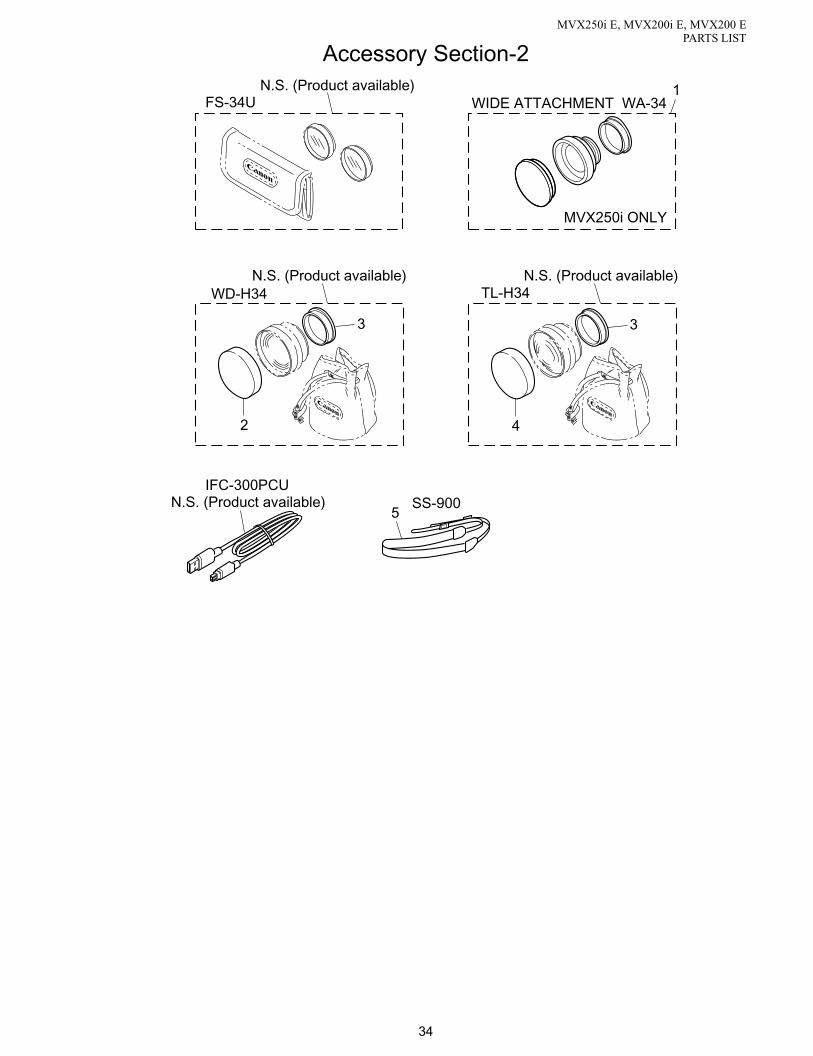
34
MVX250i E, MVX200i E, MVX200 EPARTS LIST
Accessory Section-2
5SS-900
WD-H34 TL-H34N.S. (Product available)N.S. (Product available)
3
4
3
2
N.S. (Product available)
FS-34UN.S. (Product available)
IFC-300PCU
1WIDE ATTACHMENT WA-34
MVX250i ONLY

35
MECHANICAL PARTS
SYMBOL PART NO. CLASS Q’TY DESCRIPTION REMARKS
MVX250i E, MVX200i E, MVX200 EPARTS LIST
1 D55-0240-000 000 B 1 WIDE ATTACHMENT MVX250i E NEW2 DA3-2340-000 000 B 1 CAP, FRONT NEW3 DA3-2338-000 000 B 1 CAP, REAR NEW4 DA3-2337-000 000 B 1 CAP, FRONT NEW5 D81-1470-000 000 B 1 STRAP, SHOULDER SS900

36
MVX250i E, MVX200i E, MVX200 EPARTS LIST
CAUTION - FOR CONTINUED PROTECTION AGAINST RISK OF FIRE, REPLACE FU3201, FU3202,
FU3205 ONLY WITH SAME TYPE: 0435001 1.0-24V FUSE REPLACE FU3203, FU1810
ONLY WITH SAME TYPE: 043501.5 1.5-24V FUSE MANUFACTURER: LITTELFUSE
MAIN P.C.B.
IC3201
IC301IC300
IC100
IC102
IC103
FU1810
FU3202
FU3201
FU3205
FU3203
FUSE Replacement Instruction

37
ELECTRICAL PARTS
SYMBOL PART NO. CLASS Q’TY DESCRIPTION REMARKS
MVX250i E, MVX200i E, MVX200 EPARTS LIST
MAIN P.C.BCN2102 VS1-7098-021 000 C 1 CONNECTOR 21PFU1810 VD7-2871-501 000 C 1 CHIP FUSE NEWFU3201 VD7-2871-001 000 C 1 CHIP FUSE NEWFU3202 VD7-2871-001 000 C 1 CHIP FUSE NEW
FU3203 VD7-2871-501 000 C 1 CHIP FUSE NEWFU3205 VD7-2871-001 000 C 1 CHIP FUSE NEW
JACK1 P.C.B.CN41 WS1-5716-000 000 C 1 JACK, MIC MVX250i E
CN81 WS1-5524-000 000 C 1 JACK, MINI AVCN3212 WS1-6113-000 000 C 1 JACK, DCCN3551 WS1-6247-000 000 C 1 JACK, USB NEW
JACK2 P.C.B.
CN11 WS1-6347-000 000 C 1 JACK, DV NEWCN31 WS1-6263-000 000 C 1 JACK, S-VIDEO NEWCN91 VS1-7098-021 000 C 1 CONNECTOR 21P
LCD P.C.B.
CN901 VS1-6596-027 000 C 1 CONNECTOR 27P

38
PARTS LIST
PAGE PART NO. CLASS Q’TY DESCRIPTION REMARKS
MVX250i E, MVX200i E, MVX200 EPARTS LIST
33 CD1-4054-010 000 C 1 COVER, TERMINAL NB-2L NEW3 D52-0260-000 000 B 1 CAP, LENS NEW
35 D55-0240-000 000 B 1 WIDE ATTACHMENT MVX250i E NEW35 D81-1470-000 000 B 1 STRAP, SHOULDER SS90033 D82-0643-000 000 C 1 CORD, AC(E) PLUG TYPE E
33 D82-0645-000 000 C 1 CORD, AC(AS) PLUG TYPE AS33 D83-0682-000 000 B 1 WL-D83 WIRELESS CONTROLLER(E)
MVX250i E, MVX200i E NEW33 D83-0683-000 000 B 1 WL-D83 WIRELESS CONTROLLER(PAL)
MVX200 E NEW
17 DA2-0314-000 000 C 1 SPRING, PLATE3 DA2-0436-000 000 C 1 SHOE, ACCESSARY
27 DA2-0645-000 000 C 2 WASHER29 DA2-0780-000 000 C 1 SCREW11 DA2-0909-000 000 C 1 SHAFT, LCD LOCK
11 DA2-1737-000 000 1 MAGNET, HINJI25 DA2-2115-000 000 C 1 SCREW25 DA2-2116-000 000 C 1 SPRING, COIL (DRUM)29 DA2-2128-000 000 C 1 S LOADING GEAR25 DA2-2138-000 000 C 4 SCREW
25,27,29,31 DA2-2139-000 000 C 5 WASHER31 DA2-2140-000 000 C 1 WASHER31 DA2-2188-000 000 C 1 GEAR, WHEEL31 DA2-2190-000 000 C 1 GEAR, CONNECT31 DA2-2191-000 000 C 1 LEVER, CAM
31 DA2-2192-000 000 C 1 GUIDE, TENSION CAM31 DA2-2195-000 000 C 1 GEAR, CAPSTAN31 DA2-2196-000 000 C 1 BELT, TIMING31 DA2-2197-000 000 C 1 GEAR, PULLEY27 DA2-2220-000 000 C 1 LEVER, EJECT
27 DA2-2238-000 000 C 1 BRAKE, MAIN T29 DA2-2259-000 000 C 1 SCREW29 DA2-2261-000 000 C 8 SCREW17 DA3-0161-000 000 C 1 SHIELD CASE, HA17 DA3-0941-000 000 C 3 RUBBER, INSULATION
17 DA3-1026-000 000 F 3 SCREW19 DA3-1071-000 000 C 1 SPRING, CVF CLICK19 DA3-1076-000 000 C 1 RUBBER, CVF KNOB21 DA3-1424-000 000 C 1 RUBBER, INSULATION NEW17 DA3-1426-000 000 C 1 HOLDER, SUB NEW
17 DA3-1427-000 000 C 1 SHIELD CASE, PM1 NEW17 DA3-1428-000 000 C 1 SHIELD CASE, PM2 NEW17 DA3-1429-000 000 C 3 RUBBER, HOLDER NEW9 DA3-1435-000 000 C 1 GUIDE, ACCESS LED LIGHT NEW9 DA3-1436-000 000 B 1 COVER, CARD NEW
9 DA3-1437-000 000 C 1 COVER, HINGE NEW9 DA3-1438-000 000 C 1 SHEET, BLINDFOLD MVX250i E NEW3 DA3-1439-000 000 B 1 HOLDER, LI BATT NEW9 DA3-1440-000 000 C 1 CASE, LITHIUM NEW9 DA3-1442-000 000 C 1 SHAFT, CARD COVER NEW
9 DA3-1443-000 000 C 1 BASE, TRIPOD NEW9 DA3-1445-000 000 C 1 HOOK, CARD COVER NEW3 DA3-1447-000 000 C 1 COVER, ACC SHOE MVX250i E NEW5 DA3-1456-000 000 C 1 RUBBER, LENS NEW5 DA3-1460-000 000 C 1 PLATE, MIC NEW
5 DA3-1461-000 000 C 1 SHIELD, MIC NEW5 DA3-1462-000 000 C 1 RUBBER, MIC NEW5 DA3-1463-000 000 C 1 SHEET, MIC NEW5 DA3-1465-000 000 C 1 CHARGE LED NEW5 DA3-1469-000 000 B 1 PLATE, MEGA PIXEL NEW
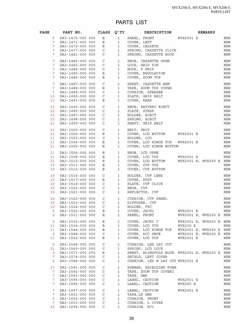
39
PARTS LIST
PAGE PART NO. CLASS Q’TY DESCRIPTION REMARKS
MVX250i E, MVX200i E, MVX200 EPARTS LIST
5 DA3-1470-000 000 B 1 PANEL, FRONT MVX250i E NEW7 DA3-1471-000 000 B 1 COVER, LEFT NEW7 DA3-1472-000 000 B 1 COVER, CASSETE NEW7 DA3-1477-000 000 C 1 SPRING, CASSETTE CLICK NEW7 DA3-1481-000 000 C 1 SPRING, CASSETTE HOOK NEW
7 DA3-1482-000 000 C 1 KNOB, CASSETTE OPEN NEW7 DA3-1483-000 000 C 1 LOCK, GRIP PIN NEW7 DA3-1484-000 000 C 1 HOOK, F GRIP NEW7 DA3-1485-000 000 B 1 COVER, REGULATION NEW7 DA3-1486-000 000 B 1 COVER, ZOOM TOP NEW
7 DA3-1487-000 000 C 1 SHEET, CASSETTE ARM NEW7 DA3-1488-000 000 B 1 TAPE, ZOOM TOP COVER NEW7 DA3-1489-000 000 C 1 CUSHION, SPEAKER NEW
13 DA3-1490-000 000 C 1 PLATE, GRIP BELT NEW13 DA3-1491-000 000 B 1 COVER, REAR NEW
13 DA3-1492-000 000 C 1 KNOB, BATTERY EJECT NEW13 DA3-1495-000 000 C 1 PLATE, STRAP NEW13 DA3-1497-000 000 C 1 HOLDER, EJECT NEW13 DA3-1498-000 000 C 1 SPRING, EJECT NEW13 DA3-1499-000 000 C 1 SHAFT, GRIP BELT NEW
13 DA3-1500-000 000 C 1 BELT, GRIP NEW11 DA3-1502-000 000 B 1 COVER, LCD BOTTOM MVX250i E NEW11 DA3-1503-000 000 C 1 HOLDER, LCD NEW11 DA3-1504-000 000 B 1 COVER, LCD HINGE TOP MVX250i E NEW11 DA3-1505-000 000 B 1 COVER, LCD HINGE BOTTOM NEW
11 DA3-1506-000 000 B 1 KNOB, LCD OPEN NEW11 DA3-1508-000 000 B 1 COVER, LCD TOP MVX250i E NEW11 DA3-1510-000 000 B 1 COVER, LCD BOTTOM MVX200i E, MVX200 E NEW19 DA3-1511-000 000 B 1 COVER, CVF TOP NEW19 DA3-1512-000 000 B 1 COVER, CVF BOTTOM NEW
19 DA3-1516-000 000 C 1 HOLDER, CVF LENS NEW19 DA3-1517-000 000 B 1 COVER, DUST NEW19 DA3-1518-000 000 C 1 PLATE, CVF CLICK NEW19 DA3-1520-000 000 C 1 KNOB, CVF NEW19 DA3-1521-000 000 C 1 REFLECTOR, CVF NEW
19 DA3-1522-000 000 C 1 CUSHION, CVF PANEL NEW19 DA3-1523-000 000 C 1 DIFFUSER, CVF NEW19 DA3-1524-000 000 C 1 HOLDER, FPC NEW5 DA3-1526-000 000 B 1 COVER, JACK2 MVX250i E NEW5 DA3-1531-000 000 B 1 PANEL, FRONT MVX200i E, MVX200 E NEW
5 DA3-1532-000 000 B 1 COVER, JACK2 C MVX200i E, MVX200 E NEW11 DA3-1534-000 000 B 1 COVER, LCD TOP MVX200 E NEW11 DA3-1544-000 000 B 1 COVER, LCD HINGE TOP MVX200i E, MVX200 E NEW3 DA3-1548-000 000 C 1 COVER, ACC SHOE MVX200i E, MVX200 E NEW
11 DA3-1552-000 000 B 1 COVER, LCD TOP MVX200i E NEW
5 DA3-1568-000 000 C 1 CUSHION, LED LAY CUT NEW11 DA3-1569-000 000 C 1 SPRING, LCD LOCK NEW9 DA3-1571-000 000 B 1 SHEET, BLINDFOLD BLUE MVX200i E, MVX200 E NEW7 DA3-1574-000 000 C 1 SHIELD, LEFT COVER NEW5 DA3-1588-000 000 C 1 CUSHION, LED W LAY CUT MVX250i E NEW
17 DA3-1591-000 000 C 1 RUBBER, SHIELDING FOAM NEW7 DA3-1592-000 000 C 1 TAPE, ZOOM TOP COVER2 NEW7 DA3-1593-000 000 C 1 TAPE, GND NEW7 DA3-1595-000 000 C 1 LABEL, CAUTION MVX250i E NEW7 DA3-1596-000 000 C 1 LABEL, CAUTION MVX200 E NEW
7 DA3-1597-000 000 C 1 LABEL, CAUTION MVX200i E NEW7 DA3-1601-000 000 C 1 TAPE,LB GND NEW5 DA3-1602-000 000 C 1 CUSHION, FRONT NEW7 DA3-1603-000 000 C 1 CUSHION, L COVER NEW
15 DA3-1604-000 000 C 1 CUSHION, RC1 NEW

40
PARTS LIST
PAGE PART NO. CLASS Q’TY DESCRIPTION REMARKS
MVX250i E, MVX200i E, MVX200 EPARTS LIST
15 DA3-1605-000 000 C 1 CUSHION, RC2 NEW11 DA3-1607-000 000 C 4 SHEET, LCD2 NEW17 DA3-1609-000 000 C 1 CUSHION, CCD CORE NEW9 DA3-1610-000 000 C 1 RUBBER, INSULATION NEW9 DA3-1611-000 000 C 1 LABEL, HOLD NEW
19 DA3-2318-000 000 C 1 MASK, CVF NEW35 DA3-2337-000 000 B 1 CAP, FRONT NEW35 DA3-2338-000 000 B 1 CAP, REAR NEW35 DA3-2340-000 000 B 1 CAP, FRONT NEW25 DA3-2345-000 000 C 1 COVER, HOUSING NEW
29 DF1-1686-000 000 C 1 DRUM BASE ASS’Y29 DF1-1687-000 000 C 1 ROLLER ASS’Y, GUIDE S29 DF1-1688-000 000 C 1 ROLLER ASS’Y, GUIDE T27 DF1-1693-000 000 C 1 BRAKE ASS’Y, TENSION27 DF1-1694-000 000 C 1 RELEASE ASS’Y, TENSION
27 DF1-1695-000 000 C 1 REVIEW ARM ASS’Y25 DF1-1703-000 000 C 1 IDLER ASS’Y27 DF1-1704-000 000 C 1 BRAKE ASS’Y, S5 DF1-5058-000 000 C 1 MIC ASS’Y NEW
13 DF1-5059-000 000 C 1 TERMINAL ASS’Y, BATTERY NEW
7 DF1-5064-000 000 C 1 ARM ASS’Y, CASSETTE NEW17 DF1-5075-000 000 C 1 HOLDER, RECORDER NEW3 DF1-5078-000 000 B 1 COVER ASS’Y, TOP NEW
29 DG1-4497-010 000 C 1 GUIDE RAIL ASS’Y29 DG1-4500-000 000 C 1 ROLLER ASS’Y, PINCH
31 DG1-4501-000 000 C 1 CHASSIS ASS’Y, MAIN29 DG1-4502-000 000 C 1 MOTOR ASS’Y, LOADING29 DG1-4503-000 000 C 1 MOTOR ASS’Y, CAPSTAN27 DG1-4504-000 000 C 1 REEL ASS’Y, S27 DG1-4505-000 000 C 1 REEL ASS’Y, T
25 DG1-4506-000 000 B 1 COMPARTMENT ASS’Y, CASSETTE17 DG3-0398-000 000 C 1 PCB ASS’Y, CAV NEW21 DG3-0399-000 000 C 1 PCB ASS’Y, CCD NEW11 DG3-0400-000 000 C 1 PCB ASS’Y, LCD NEW5 DG3-0401-000 000 C 1 PCB ASS’Y, JACK1 MVX250i E NEW
17 DG3-0402-000 000 C 1 PCB ASS’Y, JACK2 NEW9 DG3-0403-000 000 C 1 PCB ASS’Y, KEY NEW
11 DG3-0404-000 000 C 1 BACK LIGHT ASS’Y, LCD NEW19 DG3-0405-000 000 C 1 PCB ASS’Y, CVF NEW11 DG3-0406-000 000 C 1 HINGE, LCD NEW
19 DG3-0407-000 000 C 1 HINGE ASS’Y, CVF NEW7 DG3-0408-000 000 B 1 ZOOM PHOTO ASS’Y MVX250i E NEW
13 DG3-0409-000 000 B 1 SWITCH ASS’Y,POWER NEW15 DG3-0410-000 000 C 1 CONNECTOR ASS’Y, SHOE MVX250i E NEW5 DG3-0418-000 000 C 1 PCB ASS’Y, JACK1 MVX200i E, MVX200 E NEW
11 DG3-0419-000 000 C 1 FPC, LCD DETECT NEW7 DG3-0432-000 000 B 1 ZOOM PHOTO ASS’Y MVX200i E, MVX200 E NEW
23 DG3-0715-000 000 C 1 LENS ASS’Y NEW17 DH2-5172-000 000 C 1 FPC, MAIN-KEY NEW17 DH2-5173-000 000 C 1 FPC, MAIN-JACK1 NEW
17 DH2-5174-000 000 C 1 FPC, MAIN-JACK2 NEW15 DH2-5175-000 000 C 1 FPC, ACS-MAIN MVX250i E NEW21 DH2-5176-000 000 C 1 FPC, CCD-CAV NEW19 DH2-5203-000 000 C 1 FPC, CVF-CAV NEW17 DH2-5204-000 000 C 1 FPC, CAV-JACK1 NEW
11 DH2-5205-000 000 C 1 FPC, LCD-KEY NEW7 DH2-5206-000 000 C 1 FPC, SPEAKER NEW
17 DH2-5209-000 000 C 1 CABLE, MAIN-JACK1 NEW21 DH9-3009-000 000 B 1 FILTER, IR NEW29 DS1-0192-000 000 C 1 SPRING, COIL (PINCH)

41
PARTS LIST
PAGE PART NO. CLASS Q’TY DESCRIPTION REMARKS
MVX250i E, MVX200i E, MVX200 EPARTS LIST
27 DS1-0193-000 000 C 1 SPRING, COIL (TENSION)27 DS1-0198-000 000 C 1 SPRING, COIL (T BRAKE)27 DS1-0199-000 000 C 1 SPRING, COIL (S BRAKE)25 DY1-8500-000 000 E 1 DRUM ASS’Y NEW25 DY1-8501-000 000 B 1 CHASSIS ASS’Y, SLIDE
33 DY1-8528-000 000 C 1 COVER, BATTERY33 DY1-8530-000 000 C 1 LABEL, WIRELESS CONTROLER(E)
MVX250i E, MVX200i E33 DY1-8531-000 000 C 1 DC CABLE17 DY1-8609-000 000 C 1 RECORDER UNIT, DMCIII
17 DY1-8645-000 000 C 1 PCB ASS’Y, MAIN MVX250i E NEW17 DY1-8648-000 000 C 1 PCB ASS’Y, MAIN MVX200i E NEW17 DY1-8649-000 000 C 1 PCB ASS’Y, MAIN MVX200 E NEW5 DY1-8650-000 000 B 1 COVER ASS’Y, JACK1 MVX250i E NEW5 DY1-8651-000 000 B 1 COVER ASS’Y, JACK2 NEW
9 DY1-8656-000 000 B 1 COVER ASS’Y, RIGHT MVX250i E NEW9 DY1-8657-000 000 B 1 COVER ASS’Y, RIGHT MVX200i E NEW5 DY1-8658-000 000 B 1 RING ASS’Y, LENS MVX250i E NEW5 DY1-8660-000 000 B 1 RING ASS’Y, LENS MVX200i E, MVX200 E NEW
*1 11 DY1-8670-000 000 B 1 LCD ASS’Y(SELECTION) NEW
21 DY1-8671-000 000 C 1 CCD ASS’Y NEW5 DY1-8673-000 000 B 1 COVER ASS’Y, JACK1 MVX200i E, MVX200 E NEW
33 DY1-8674-000 000 C 1 LABEL, WIRELESS CONTROLER(PAL)MVX200 E NEW
19 DY1-8678-000 000 B 1 COVER ASS’Y, CVF INNER TOP NEW
9 DY1-8681-000 000 B 1 COVER ASS’Y, RIGHT MVX200 E NEW5 DY1-8682-000 000 B 1 COVER ASS’Y, FRONT MVX250i E NEW5 DY1-8683-000 000 B 1 COVER ASS’Y, FRONT MVX200i E, MVX200 E NEW
19 DY1-8703-000 000 B 1 COVER ASS’Y, CVF INNER BOTTOM NEWVD7-2871-001 000 C 3 CHIP FUSE NEW
VD7-2871-501 000 C 2 CHIP FUSE NEWVS1-6596-027 000 C 1 CONNECTOR 27PVS1-7098-021 000 C 2 CONNECTOR 21P
17 WE8-6147-000 000 C 1 CORE, FERRITE NEW21 WE8-6201-000 000 C 1 CORE, FERRITE NEW
19 WG2-5241-000 000 C 1 LCD ASS’Y, CVF*2 11 WG2-5272-000 000 B 1 LCD ASS’Y NEW
7 WR1-5090-000 000 C 1 SPEAKERWS1-5524-000 000 C 1 JACK, MINI AVWS1-5716-000 000 C 1 JACK, MIC MVX250i E
WS1-6113-000 000 C 1 JACK, DCWS1-6247-000 000 C 1 JACK, USB NEWWS1-6263-000 000 C 1 JACK, S-VIDEO NEWWS1-6347-000 000 C 1 JACK, DV NEW
3 XA1-3170-507 000 F 4 SCREW
25,29,31 XA1-7140-147 000 C 3 SCREW3,15,17 XA1-7170-207 000 F 4 SCREW
3,15,17,19 XA1-7170-257 000 F 16 SCREW3,7 XA1-7170-307 000 F 12 SCREW
3,5,7,15 XA1-7170-357 000 F 10 SCREW
11 XA1-7170-407 000 F 2 SCREW3 XA1-7170-507 000 F 1 SCREW3 XA1-7170-557 000 F 1 SCREW
23 XA4-5170-457 000 F 2 SCREW13,23 XA4-9170-357 000 F 3 SCREW
3,5,9,13,19 XA4-9170-407 000 F 8 SCREW13,23 XA4-9170-457 000 F 8 SCREW NEW
7 XA4-9170-459 000 F 5 SCREW NEW3,5,9,21 XA4-9170-507 000 F 14 SCREW
13 XA4-9170-557 000 F 1 SCREW

42
PARTS LIST
PAGE PART NO. CLASS Q’TY DESCRIPTION REMARKS
MVX250i E, MVX200i E, MVX200 EPARTS LIST
3 XA4-9170-607 000 F 1 SCREW11 XA4-9170-907 000 F 1 SCREW NEW19 XA9-1166-000 000 F 1 SCREW17 XA9-1167-000 000 F 3 SCREW23 YH8-2015-000 000 C 1 IG METER ASS’Y NEW
19 YN1-3090-000 000 C 1 LENS, EYEPIECE 1 NEW19 YN1-3093-000 000 C 1 LENS, EYEPIECE 2 NEW

BLOCK DIAGRAMS
CONTENTS
INTERCONNECTION DIAGRAM
BLOCK DIAGRAMS
CAMERA SECTION-1
CAMERA SECTION-2
CAMERA SECTION-3
CAMERA SECTION-4
SYSTEM CONTROL SECTION
SERVO SECTION
AUDIO-VIDEO SECTION-1
AUDIO-VIDEO SECTION-2
POWER SUPPLY SECTION
LCD P.C.B. SECTION
JACK1,2 SECTION

( DIGITAL MECHANICAL CHASSIS II )DMC III
MAINCHASSIS
DRUMMOTOR
LOADINGMOTOR
SLIDECHASSIS
VIDEOHEAD
SD CARD
MIC UNIT
DV JACK
S JACK
HINGE UNIT
LENSUNIT
ZOOM MOTOR
FOCUS MOTOR
FOCUS SENS
ZOOM SENS
TEMP SENS
IG METER
Metal contact (Pins' face up)Metal contact (Pins' face down)
: :
BACK LIGHT
LCD
LCD UNIT
Metal contact Metal contact
CCD P.C.B.
BATTERY TERMINAL
OPERATION KEY UNIT
CVF P.C.B.
LCD P.C.B.
1
5
21P
21P
18P
18P
11P
11P 10P
7P
7P
10P
10P
IC3201
IC301
IC300
IC100
IC102
IC103
CN3201
CN3202
CN101CN1100
CN303CN302CN100CN2000
CN2102
CN2101
CN891
CN102 CN103CN2900
1
2
1
5
1
8A1
B1
1
2 20
211 181 10
1 7
1 2
21 20
2
26
1
25 1211
21
A1B1
A1
B1B15A15
A12
B12
CN300
CN301110
111
IC1810
IC1811IC3203
IC1101
IC1102
IC1103
IC2300
IC2301
IC2000
IC2302
MAIN P.C.B.
CN107018
2
19
1
IC1070
IC1002
CN1000218119
CN1501222123
CN1200
2829
21
CN7018
1
IC1004
IC1001
IC801
CN1001B60
A60
IC1501IC1200
B1
A1
CAV P.C.B.
7
1
8
2CN42
CN431
4
CN51
2
26
1
25
CN32111
2
MIC JACK
AV JACK
USB JACK
DC JACK
IC1601
IC1602
JACK1 P.C.B.
CN91 121220
CN31 CN11
JACK2 P.C.B.
2
1
22
23
CN4101
122 CN4102
1
23
2
24
CN902
1
4CN903
1 2
25 26
CN901
IC902
IC901
IC4201
CN10051
1
50
2
CN102
1 2
27 26
CN101
KEY P.C.B.
SPEAKER FPC UNIT
LCD
24P
12
5150
LCD DETECT FPC
51P
51P
27P
5P
26P
26P
4P
4P
24P
27P
2P
5P
8P
120P
120P19P
29P
8P
23P
23P 22P
22P
SHOE CONNECTOR
12P
19P
4P
ZOOM PHOTO KEY UNIT
10P
21P
21P
26P
12P
2P
26P
4P
8PCN41
CN81
CN3551
CN3212
B60A60
INTERCONNECTION DIAGRAM MVX250i E,MVX200i E,MVX200 E
CANON INC. 2004C01 Mar. 2004

CN100123456789
10CN101
12345678CN102
123456789
101112131415161718192021222324252627282930313233343536373839404142434445464748495051
CN103A1A2A3A4A5A6A7A8A9
A10A11A12A13A14A15B1B2B3B4B5B6B7B8B9
B10B11B12B13B14B15
CN300123456789
1011
CN301123456789
10
SP2 +SP1 −GNDCK 3VZOOM ADPICT SWKEY LED0P5VHALF PHOTO SWPHOTO SW
NET PW SWVTR PW SWCAM PW SWSTART/STOP SWGNDTAPE/CARD SWGRN/P.AEN.C
GNDCARD DAT3CARD CMDGNDCARD SCKCARD VSS1GNDCARD DAT2CARD DATGNDCARD DAT1GNDGNDDVDD2.7VCARD DETCARD PAODVDD3VN.CKEY AD0KEY AD1KEY AD2KEY AD4LI 3VCARD ACCESS LED GNDPNL OP SWPNL B/T SWPANEL RPANEL GPANEL BGNDGNDC SYNCLCD2.7VLCD2.7VLCD5VLCD8.5VLCD CSLCD EEP CSLCD EEP SOUTLCD EEP SCKLCD EEP SIN1LCD ONLCD BL ONVTR UNREGVTR UNREGVTR UNREGMO GNDMO GNDMO GNDMO GND
MODE RESETEPMCECNVSSN.CDEBCLKGNDDEBUDGNDDEBDDGNDXDEBENGNDGNDE3V+LI3VGNDFLASH CLKFLASH RSTFLASH RXD1FLASH TXD1N.CDVDD3VCG CSEEP/CG CLKEEP/CG SODOT CLKOSD I0OSD I1VIC HDVIC VD
UUVVDFGDPGSENS COMSENS GARDCOIL COMWW
LOAD(+)LOAD(+)MSW VSSMSW VCCMSW SENSLOAD(−)LOAD(−)DEW +DEW −N.C
MAIN P.C.B.
CN302123456789
101112131415161718
CN303123456789
101112131415161718192021
CN891123456789
101112
UCOILUCOILWCOILWCOILVCOILVCOILC H −W −W +C H +U +U −V +V −CFG2CFG GNDCFG VCCCFG1
BOT EBOT CMIC GNDMIC3REC PRFMIC2MIC1TIN −TOUT −TIN +TOUT +C INCIN GNDLED ALED KSIN −SOUT −SIN +SOUT +EOT EEOT C
SHOE UNREGSHOE UNREGPOW GNDPOW GNDPOW GNDID-1ST VDHGLST STSPID-2ADV MIC GNDADV MIC LADV/EXT MIC R
MAIN P.C.B.
CN1100A1A2A3A4A5A6A7A8A9
A10A11A12A13A14A15A16A17A18A19A20A21A22A23A24A25A26A27A28A29A30A31A32A33A34A35A36A37A38A39A40A41A42A43A44A45A46A47A48A49A50A51A52A53A54A55A56A57A58A59A60B1B2B3B4B5B6B7B8B9
B10B11B12B13B14B15B16B17B18B19B20B21B22B23B24B25B26B27B28B29B30B31B32B33B34B35B36B37B38B39B40B41B42B43B44B45B46B47B48B49B50B51B52B53B54B55B56B57B58B59B60
CN20001234567
ADV/EXT MIC RADV MIC GNDGNDRAWDATA[0]RAWDATA[1]RAWDATA[2]RAWDATA[3]GNDRAWDATA[4]RAWDATA[5]RAWDATA[6]RAWDATA[7]GNDRAWDATA[8]RAWDATA[9]RAWDATA[10]RAWDATA[11]GNDDSP CLKGNDXTGHDXTGVDVGATEF RES SWZ RES SWMO GNDMO GNDCAM3VCAM3VCCD15VCCD−7VGNDGNDGNDGNDAMCKWCKAIF SOAIF CSAIF SCLKXPDIREC MUTEA MUTEEXT DETHP MUTESOUNDHP ONSP +SP −SP GNDSP GNDAA4.7VAA4.7VAA2.7VAA2.7VAA GNDAA GNDV I/O/HP RAV L/HP LAV RADV MIC LADV MIC GNDPWM IRISPWM NDPWM FAPWM FBPWM ZAPWM ZBDA LOADCAM SCKCAM SOAFE CSF PSBZ PSBIRIS PSBIRIS CLND PSBDA CFGSUB CONTAFE RSTI ENCGNDND ENCLED RETTEMPP GYROY GYROI SWP GY OUTAVDD2.7VY GY OUTDVDD2.7VP5VP5VAUD2 IMACS1 ILRCKC SYNCEVF COMGNDGNDEVF REVF GEVF BGNDEVF 3V ONEVF 8.5V ONVF B EVFVF G EVFVF R EVFGNDEVF HDEVF SENEVF EEP CSLCD EEP SCKLCD EEP SIN1LCD EEP SOUTLCD8.5VLCD2.7VLCD2.7V
HA GNDH1AH1BHA GNDH2AH2BHA GND
MAIN P.C.B.
CN2101123456789
1011121314151617181920212223242526
CN2102123456789
101112131415161718192021
CN2900A1A2A3A4A5A6A7A8A9
A10A11A12B1B2B3B4B5B6B7B8B9
B10B11B12
CN320112CN3202
12345
AV GNDAV L/HP LAV RAV GNDV I/O/HP RAV GNDAV DETCAM LEDAVDD2.7VY GY OUTGY GNDP GY OUTGNDGNDD +N.CD −GNDGNDVBUSP5VGNDDC J SWRMC INCHAGE LEDVTR UNREG
YC GNDC I/OYC GNDYC GNDYC GNDY I/OS DETYC GNDYC GNDEJECT SWDIAL CWDIAL CCWKEY AD3GNDGNDTPAXTPAXTPBTPBGNDN.C
V I/OGNDVTR POW SWN.CCAM POW SWFCH OTCKSWPGNDPBRFEVF REVF GEVF HDMODE RESETVTR ON IC3201VTR UNREGMIC2MIC3TRSTTMSTDITDOEVF COMEVF B
DC −DC +
BATT −BATT −BATT INFO ADBATT +BATT +
MAIN P.C.B.
CN901123456789
101112131415161718192021222324252627
CN902123456789
101112131415161718192021222324
CN9031234
MO GNDMO GNDMO GNDVTR UNREGVTR UNREGVTR UNREGLCD BL ONLCD ONLCD EEP SIN1LCD EEP SCKLCD EEP SOUTLCD EEP CSLCD CSLCD8.5VLCD5VLCD2.7VLCD2.7VC SYNCGNDGNDGNDPANEL BPANEL GPANEL RGND SWPANEL BT SWPANEL BT SW
TESTRGTBLUEREDGREENPSIGHCK1HCK2WIDETESTREFHSTPCGXSTBYVSSGN.CVSSVDDDWNENVCKVSTCSCOM
PANEL BT SWGND SWLCD2.7VN.C
LCD P.C.B.
CN1070123456789
10111213141516171819
N.CVH(+15V)GNDH2GNDH1GNDRESETGNDVSUBV4V3V2V1SUB SWCAM3VVL(−7.5V)GNDCCD OUT
CCD P.C.B.
CN4101123456789
1011121314151617181920212223
CN4102123456789
10111213141516171819202122
P5VCOMCKV1CKV2STVXSTVXENBENBVBBDSDXDSGDSGBL2.7VBRGVDDCKH2CKH1STHXSTHVSSVSS
COMCKV1CKV2STVXSTVXENBENBCSVVBBDSDXDSGDSGBRGCSHVDDCKH2CKH1VSSSTHXSTH
CVF P.C.B.
CN4212345678CN43
1234CN51
123456789
1011121314151617181920212223242526
CN321112
EXT LMIC GNDADV/EXT MIC REXT P DETINT MIC GNDINT MIC RINT MIC GNDINT MIC L
INT MIC GNDINT MIC RINT MIC GNDINT MIC L
VTR UNREGCHAGE LEDRMC INDC J SWGNDP5VVBUSGNDGNDD −N.CD +GNDGNDP GY OUTGY GNDY GY OUTAVDD2.7VCAM LEDAV DETAV GNDV I/O/HP RAV GNDAV RAV L/HP LAV GND
DC +DC −
JACK1 P.C.B.
CN91123456789
101112131415161718192021
GNDTPBXTPBXTPATPAGNDGNDKEY AD3DIAL CCWDIAL CWEJECT SWYC GNDYC GNDS DETY I/OYC GNDYC GNDYC GNDC I/OYC GNDN.C
JACK2 P.C.B.
CN1200123456789
1011121314151617181920212223242526272829
CN1501123456789
1011121314151617181920212223
ND DRIVE(−)ND DRIVE(+)ND HALL IN(+)ND HALL OUT(+)ND HALL IN(−)ND HALL OUT(−)GNDZOOM BZOOM−B ZOOM−AZOOM AFOCUS−AFOCUS AFOCUS BFOCUS−BTEMPTEMP 2.7VFOCUS VCCFOCUS LEDFOCUS SENSZOOM SENSZOOM VCCZOOM LEDIG DRIVE(−)IG DRIVE(+)IG HALL IN(+)IG HALL OUT(+)IG HALL IN(−)IG HALL OUT(−)
VSSXSTHSTHCKH1CKH2VDDGRBBL2.7VDSGXDSGDSDVBBENBXENBXSTVSTVCKV2CKV1COMP5VP5V
CAV P.C.B.
CN1001A1A2A3A4A5A6A7A8A9
A10A11A12A13A14A15A16A17A18A19A20A21A22A23A24A25A26A27A28A29A30A31A32A33A34A35A36A37A38A39A40A41A42A43A44A45A46A47A48A49A50A51A52A53A54A55A56A57A58A59A60B1B2B3B4B5B6B7B8B9
B10B11B12B13B14B15B16B17B18B19B20B21B22B23B24B25B26B27B28B29B30B31B32B33B34B35B36B37B38B39B40B41B42B43B44B45B46B47B48B49B50B51B52B53B54B55B56B57B58B59B60
ADV/EXT MIC RADV MIC GNDGNDRAWDATA[0]RAWDATA[1]RAWDATA[2]RAWDATA[3]GNDRAWDATA[4]RAWDATA[5]RAWDATA[6]RAWDATA[7]GNDRAWDATA[8]RAWDATA[9]RAWDATA[10]RAWDATA[11]GNDDSP CLKGNDXTGHDXTGVDVGATEF RES SWZ RES SWMO GNDMO GNDCAM3VCAM3VCCD15VCCD−7VGNDGNDGNDA CLK GNDAMCKWCKAIF SOAIF CSAIF SCLKXPDIREC MUTEA MUTEEXT DETHP MUTESOUNDHP ONSP +SP −SP GNDSP GNDAA4.7VAA4.7VAA2.7VAA2.7VAA GNDAA GNDV I/O/HP RAV L/HP LAV RADV MIC LADV MIC GNDPWM IRISPWM NDPWM FAPWM FBPWM ZAPWM ZBDA LOADCAM SCKCAM SOAFE CSF PSBZ PSBIRIS PSBIRIS CLND PSBDA CFGSUB CONTAFE RSTI ENCGND ND ENCLED RETTEMPP GYROY GYROI SWP GY OUTAVDD2.7VY GY OUTDVDD2.7VP5VP5VAUD2 IMACS1 ILRCKC SYNCEVF COMGNDGNDEVF REVF GEVF BGNDEVF 3V ONEVF 8.5V ONVF B EVFVF G EVF VF R EVFGNDEVF HDEVF SENEVF EEP CSLCD EEP SCKLCD EEP SIN1LCD EEP SOUTLCD8.5VLCD2.7VLCD2.7V
CAV P.C.B.
CN70112345678CN1000
123456789
10111213141516171819
EXT LMIC GNDADV/EXT MIC REXT P DETINT MIC GNDINT MIC RINT MIC GNDINT MIC L N.CCCD OUTGNDVL(−7.5V)CAM3VSUB SWV1V2V3V4VSUBGNDRESETGNDH1GNDH2GNDVH(+15V)
CAV P.C.B.
CN100123456789
10111213
CN101123456789
101112131415161718192021222324252627282930313233343536373839404142434445464748495051
CN102123456789
101112131415161718192021222324252627
MMC RSVMMC CMDMMC VSS1-1MMC VDDMMC SCKMMC VSS1-2MMC DATMMC DAT1MMC DAT2CARD PROGNDCARD DETM GND
MO GNDMO GNDMO GNDVTR UNREGVTR UNREGVTR UNREGLCD BL ONLCD ONLCD EEP SIN1LCD EEP SCKLCD EEP SOUTLCD EEP CSLCD CSLCD8.5VLCD5VLCD2.7VLCD2.7VC SYNCGNDGNDPANEL BPANEL GPANEL RPNL B/T SWPNL OP SWGNDCARD ACCESS LEDLI 3VKEY AD4KEY AD2KEY AD1KEY AD0N.CDVDD3VCARD PROCARD DETDVDD2.7VGNDGNDCARD DAT1GNDCARD DATCARD DAT2GNDCARD VSS1CARD SCKGNDCARD CMDCARD DAT3GNDGND
PNL B/T SWGNDPANEL RPANEL GPANEL BGNDGNDGNDC SYNCLCD3VLCD3V LCD5VLCD8.5VLCD CSLCD EEP CSLCD EEP SOUTLCD EEP SCKLCD EEP SIN1LCD ONLCD BL ONVTR UNREGVTR UNREGVTR UNREGMO GNDMO GNDMO GNDMO GND
KEY P.C.B.
INTERCONNECTION DIAGRAM

DIGITAL AUDIO SIGNALDIGITAL VIDEO SIGNALANALOG AUDIO SIGNALANALOG VIDEO SIGNAL
IC801AK4567
AUDIO INTERFACE
K5
H9
G10
E9
D10
G9
H1
G1
F1 H2
H1
RG
SUBCK
V1
V2
V3
V4
CCD IN
CLIJ2
IC1002AD9929BBCZ
TG/CDS/AGC/AD
/V-DRIVER
IC1004MM1612JM
2.8V REGULATOR
IC1001SN74LVC/GU04DCK3
INVERTER
D2HD
VD
DCLK2/FD
SYNC/VGATE
OUT CONT
SCK
SL
SDATA
D11
D1
C1
C9
D9
J10
K10
K9
A2
B2
A3
B3
A4
B5
B6
A6
B7
A7
A8
B8D0
4 V OUT 5V IN
3 1
42
404134471932
28
26
39
44
45
27
25
36
35
31
29
21
20
223 2413
12
7
6
5
4
3
14 16 17
12H2
11H1
10RG
13SUB
1V4
2V3
3V2
4V1
6RC
8VOUT
14VL
7VDD
IC1070ICX475AK-K
CCD
CAV P.C.B. (1/2)CCD P.C.B.
VSUB
RESET
XTGHD
SUB CONT
XTGVD
DSP CLK
VGATE
AFE RST
CAM SCK
AFE CS
CAM SO
RAWDATA (11)
RAWDATA (10)
RAWDATA (9)
RAWDATA (8)
RAWDATA (7)
RAWDATA (6)
RAWDATA (5)
RAWDATA (4)
RAWDATA (3)
RAWDATA (2)
RAWDATA (1)
RAWDATA(0)
CN701
EXT LADV/EXT MIC R
INT MIC RINT MIC L
CAM SCKCAM SO
1358
CN1000
CCD OUTVL(−7.5V)
CAM3VSUB SW
V1V2V3V4
VSUBRESET
H1H2
VH(+15V)
2456789
101113151719
LRCK
WCK
AUD2 I
MACS1 I
AIF SO
AIF
CS
AIF
SC
LK
RE
C M
UTE
XP
DI
AMCK
AUDIOI/F
CONTROLLER
CONTROLREGISTER
I/F
HPFFIL1FIL2EQ
FIL3
+2dbto
−2db
−24db+12db
0db
OFFSETCANCEL
HPF
MIXER&
DEM
OFFSETCANCEL
HPFADC
PRE AMP
PRE AMP
SPK AMPALC2
MIXDAC OPGA
ALC1
LINE OUT
HP AMP
OVFDETECT
MICPOWER
AA2.7V AA4.7VP5VAA4.7V
Q803
Q804
SP−
SP+
Q801
Q824Q802
Q821
MUTEDL
Q822,Q823
POWERON MUTE
Q823
Q806
Q807
Q805
Q825
AFE CSSUB CONTAFE RST
RAWDATA(0)RAWDATA(1)RAWDATA(2)RAWDATA(3)RAWDATA(4)RAWDATA(5)RAWDATA(6)RAWDATA(7)RAWDATA(8)RAWDATA(9)
RAWDATA(10)RAWDATA(11)
AV L/HP LAV R
ADV/EXT MIC RCA-3
EXT DETHP MUTE
AV-1V I /O/HP RADV MIC L
SOUNDAMCKWCK
AIF SOAIF CS
AIF SCLKXPDI
REC MUTESP+SP−
LRCKAUD2 IMACS/ICAM3VCAM3V
CCD15VCCD−7VAA4.7VAA4.7VAA2.7VAA2.7V
P5VP5V
DSP CLKXTGHDXTGVDVGATE
CN1001A19A21A22A23B12B19B20A4A5A6A7A9
A10A11A12A14A15A16A17A59A60A1
A43A44A45A47A58B1
A46A36A37A38A39A40A41A42A48A49B37B35B36A28A29A30A31A52A53A54A55B33B34
TOCAMERA SECTION-4MAIN P.C.B.CN1100
TOCAMERA SECTION-2CAV P.C.B.
TOSYSTEMCONTROLSECTIONMAIN P.C.B.CN1100
TOAUDIO-VIDEOSECTION-1MAIN P.C.B.CN1100
TOJACK 1,2SECTIONJACK1 P.C.B.CN42
CCD15VCAM3V
2.8V CAM3V
HP MUTE
HP ON
V I /O/HP R
A MUTE
ADV/EXT MIC R
EXT DET
ADV MIC L
X1001
CCD−7V
CCD15V
CCD−7VCAM3V
AA4.7V
AA2.7V
P5V
42
CN1070CAM 3V
H2H1
RESETVSUB
V4V3V2V1
SUB SWCCD OUTVL (−7.5)VH(+15V)
16468
10111213141519172
Q1074
Q1071Q1073
CAM 3V
CAMERA SECTION-1
CANON INC. 2004C01 Mar. 2004
MVX250i E, MVX200i E, MVX200 E

CAMERA SECTION-2
C CANON INC. 200401 Mar. 2004
MVX250i E, MVX200i E, MVX200 E
4CLK
3DI
31AELEV2
42
48
45
40
51
1
5LD
6428
27
29
62
60
30
EVF A2.7V
LCD 2.7V
LCD 8.5V
P5V
DVDD2.7V
AVDD2.7V
AVDD 2.7VDVDD 2.7V
CAM 3V
Q1200
PWM FAPWM FBPWM ZAPWM ZB
Z PSBF PSB
PMW IRISDA CFG
Y GY OUTP GY OUTDA LOADIRIS CL
IRIS PSBI SW
P GYROY GYRO
I ENCCAM SO
CAM SCKZ RES SW
TEMPF RES SWLED RETVF B EVFVF G EVFVF R EVF
ND ENCND PSBPWM ND
LCD EEP SCKLCD EEP SOUT
CN1001
TOLENS UNIT
XSTHSTH
CKH1CKH2
GRB
DSGXDSGENB
XENBXSTVSTV
CKV2CKV1COMDSDVDD
BL2.7VP5VP5V
CN15012345789
111215161718192021136
102223
B52B39B43B42B44B55B57B53B46B47B54B56B30B32B58B59B60
B23B17B4B5B6B7B8
B14B13B3
B18B29B31B9
B16B15B28B26B27B21B11B10A25B25A24B24B48B49B50B38
ND HALL OUT (− )ND HALL IN (− )
ND HALL OUT (+ )ND HALL IN (+ )ND DRIVE (+ )ND DRIVE (− )
FOCUS AFOCUS B
FOCUS −BFOCUS −AZOOM −BZOOM B
ZOOM −AZOOM A
IG DRIVE (+ )IG DRIVE (− )
IG HALL IN (+ )IG HALL OUT (+ )
IG HALL IN (− )IG HALL OUT (− )
FOCUS VCCZOOM SENS
TEMPFOCUS SENS
ZOOM LEDFOCUS LED
CN1200
654321
1314151298
1011252426272829182116202319 HALL2− IN
HALL2−OUT
HALL2+OUT
HALL2+ IN
OUT1B
OUT1
IG HALL IN (− )
IG HALL OUT (− )
46 VC2
IG HALL OUT (+ )
IG HALL IN (+ )
IG DRIVE (− )
IG DRIVE (+ )
25
19
61
8
21
32
VDD
VC1
VM1
VM2
VM3
VM4.5
GYRIN1
GYRIN2
GYRLEV2
GYRLEV1
GAIN1 2
EN1
IRIS CONT
Y GYRO
I ENC
CAM SO
CAM SCK
EVF HD
C SYNC
VF B EVF
VF G EVF
VF R EVF
LCD EEP SCK
LCD EEP SOUT
EVF SEN
Y GY OUT
DA LOAD
P GYRO
P GY OUT
I SW
IRIS PSB
IRIS CL
IC1501LV4141W
EVF DRIVER
55BIN
54GIN
53RIN
15HD
8
7DATA
12
11
57SYNC IN
1
6
20
43
19
17
18
40
50 DSDOUT
47 VCC 2
13 BLSW
39 VCCCOM
38 COMOUT
28 CKV1
27 CKV2
26 STV
25 XSTV
29 XENB
30 ENB
23 XDSG
24
45
49
DSG
BOUT
GOUT
ROUT
CKH 2
CKH 1
STH
XSTH
DSD
COM
CKV1
CKV2
STV
XSTV
XENB
ENB
XDSG
DSG
B
G
R
CKH2
CKH1
STH
XSTH
SCLK
HDIN
VDD 0
VDD 2
VDD 1
VCC 1
LOAD
IC1200BH9921KS2LENS DRIVE
14
18
16
15IN 4
2
12VDD
13
22
7
24
26
20
9
10
6
17
OUT 4
OUT 4B
OUT 5B
OUT 5
OUT 2B
OUT 3B
OUT 3
OUT 2
IG ZOOM A
IG ZOOM −A
IG ZOOM −B
IG ZOOM B
IG FOCUS −A
IG FOCUS −B
37
35
36
56
58
33
OUT 6B
OUT 6
HALL1+ IN
HALL1− IN
HALL1+OUT
HALL1−OUT
ND DRIVE (− )
ND DRIVE (+ )
ND HALL IN (+ )
ND HALL IN (− )
ND HALL OUT (+ )
ND HALL OUT (− )
IG FOCUS B
IG FOCUS A
EN 2
EN 3
EN 4 5
IN 5
IN 3
IN 2
PWM ZA
F PSB
Z PSB
PWM ZB
PWM FB
PWM FA63IN 1
PWM IRIS38AELEV 1
55
53DAC 3 OUT
EN 6
ND ENC
DA CFG
HD PSB54IN 6
PWM ND
AVDD 2.7V
BACKLIGHT
A8.5V
A8.5V
P5V
Q1510
Q1506
Q1508
Q1507
EVF HDEVF COM
EVF GEVF REVF B
EVF SENEVF 3V ON
EVF 8.5V ONEVF EEP CS
LCD EEP SIN 1AVDD 2.7VDVDD 2.7VLCD 8.5VLCD 2.7VLCD 2.7V
CSYNC
TOCAMERA SECTION-4MAIN P.C.B.CN1100
TOCAMERA SECTION-1CAV P.C.B.
TOAUDIO-VIDEO SECTION-4MAIN P.C.B.CN1100
TOSYSTEM CONTROL SECTIONMAIN P.C.B.CN1100
P5VBL2.7V
COMCKV1CKV2STV
XSTVXENBENBDSD
XDSGDSG
BRG
VDDCKH2CKH1STH
XSTH
CN4101Q4101
1132345678
1011121415161718192021
COMCKV1CKV2STV
XSTVXENBENBDSD
XDSGDSG
BRG
VDDCKH2CKH1STH
XSTH
CN41021234567
1011121314151718192122
60
CAM SOCAM SCK
CAV P.C.B.(2/2)
CVF P.C.B.
LCD(CVF)

USB SIGNAL
F25
G22
G23
G24
G25
H22
H24 J22
J23
MA
DD
R U
(11)
J25
MA
DD
R U
(13)
MA
DD
R U
(14)
F24
F23
E25
MA
DD
R U
(0)
MA
DD
R U
(1)
MA
DD
R U
(2)
MA
DD
R U
(3)
MA
DD
R U
(4)
MA
DD
R U
(5)
MA
DD
R U
(6)
MA
DD
R U
(7)
MA
DD
R U
(8)
MA
DD
R U
(9)
MA
DD
R U
(10)
M22
MD
QM
C(0
)
M23
MD
QM
U(1
)
E23
MD
QM
U(2
)
E24
MD
QM
U(3
)
K24
MC
KE
U
K25
MC
LK U
L24
XM
CS
U
L23
XM
CA
S U
L22
XM
CA
S U
L25
XM
WE
U
K23
V22EADDR M(0)
V23EADDR M(1)
V24EADDR M(2)
V25EADDR M(3)
W22EADDR M(4)
W23EADDR M(5)
W24EADDR M(6)
W25EADDR M(7)
Y23EADDR M(8)
Y24EADDR M(9)
Y25EADDR M(10)
AA22EADDR M(11)
AA23EADDR M(12)
AA24EADDR M(13)
AB25EADDR M(14)
AB22EADDR M(15)
AB23EADDR M(16)
AD23EDATA M(0)
AE23EDATA M(1)
AD22EDATA M(2)
AE22EDATA M(3)
AC21EDATA M(4)
AD21EDATA M(5)
AE21EDATA M(6)
W1MCCLK A
Y4MCDT A(3)
Y3MCDT A(2)
Y2MCDT A(1)
Y1MCDT A(0)
W2MCCMD A
AB16RDY
AC17XECS M
AB18XEWRL M
AB17XEWRU M
AC16XERD M
AC15DREQ (0)
AE17XDACK (0)
T2TRST
T3TMS
T1TCK
T4TDO
AE14
AD13DN USB
DP USB
AD1XRESET
J2STROBE TMG(1)
AB20EDATA M(7)
AC20EDATA M(8)
AD20EDATA M(9)
AB19EDATA M(10)
AC19EDATA M(11)
AD19EDATA M(12)
AE19EDATA M(13)
AD18EDATA M(14)
AE18EDATA M(15)
AB24EADDR M(17)
AC25EADDR M(18)
AC23EADDR M(19)
AC24EADDR M(20)
AC25EADDR M(21)
AD24EADDR M(22)
IC1103(1/2)MB87M1982BGL-GE1
DIGIC DV
27
A2
60
A3
61
A4
62
A5
63
A6
64
A7
65
A8
66
A9
24
A10
/AP
21
NC
2
22
BA
0
23
BA
1
2DQ0
4DQ1
5DQ2
7DQ3
8DQ4
10DQ5
11DQ6
13DQ7
74DQ8
76DQ9
77DQ10
79DQ11
80DQ12
82DQ13
83DQ14
85DQ15
31DQ16
33DQ17
34DQ18
36DQ19
37DQ20
39DQ21
40DQ22
42DQ23
45DQ24
47DQ25
48DQ26
50DQ27
51DQ28
53DQ29
54DQ30
56DQ31
C21 MDATA L(0)
B20 MDATA L(1)
C20
D20
MDATA L(2)
A19
MDATA L(3)
B19
MDATA L(4)
D19
MDATA L(5)
A18
MDATA L(6)
B18
MDATA L(7)
C18
MDATA L(8)
D18
MDATA L(9)
A17
MDATA L(10)
B17
MDATA L(11)
D17
MDATA L(12)
A16
MDATA L(13)
C16
MDATA L(14)
D8
MDATA L(15)
A7
MDATA L(16)
B7
MDATA L(17)
C7
MDATA L(18)
D7
MDATA L(19)
B6
MDATA L(20)
C6
MDATA L(21)
A5
MDATA L(22)
C5
MDATA L(23)
D5
MDATA L(24)
B4
MDATA L(25)
C4
MDATA L(26)
A3
MDATA L(27)
B3
MDATA L(28)
A2
MDATA L(29)
MDATA L(30)
D6
MDATA L(31)
2DQ0
4DQ1
5DQ2
7DQ3
8DQ4
10DQ5
11DQ6
13DQ7
74DQ8
76DQ9
77DQ10
79DQ11
80DQ12
82DQ13
83DQ14
85DQ15
31DQ16
33DQ17
34DQ18
36DQ19
37DQ20
39DQ21
40DQ22
42DQ23
45DQ24
47DQ25
48DQ26
50DQ27
51DQ28
53DQ29
54DQ30
56DQ31
U25 MDATA U(0)
U22 MDATA U(1)
T25
T24
MDATA U(2)
T22
MDATA U(3)
R25
MDATA U(4)
R24
MDATA U(5)
R23
MDATA U(6)
R22
MDATA U(7)
P25
MDATA U(8)
P24
MDATA U(9)
P23
MDATA U(10)
N25
MDATA U(11)
M24
MDATA U(12)
M25
MDATA U(13)
M24
MDATA U(14)
B25
MDATA U(15)
C25
MDATA U(16)
D25
MDATA U(17)
A24
MDATA U(18)
B24
MDATA U(19)
C24
MDATA U(20)
D24
MDATA U(21)
B23
MDATA U(22)
C23
MDATA U(23)
D23
MDATA U(24)
A22
MDATA U(25)
B22
MDATA U(26)
C22
MDATA U(27)
A21
MDATA U(28)
B21
MDATA U(29)
MDATA U(30)
A23
MDATA U(31)
26
A1
25
A0
16
DQ
M0
71
DQ
M1
28
DQ
M2
59
DQ
M3
67
CK
E
68
CLK
20
/CS
19
/RA
S
18
/CA
S
17
/WE
IC1102HY57V643220CTP-7
SDRAM
IC1101HY57V643220CTP-7
SDRAM
A9
C10
A10
D11
C11
B11
A11
D12
C11
MA
DD
R L
(11)
A12
MA
DD
R L
(13)
MA
DD
R L
(14)
B9
C9
D9
MA
DD
R L
(0)
MA
DD
R L
(1)
MA
DD
R L
(2)
MA
DD
R L
(3)
MA
DD
R L
(4)
MA
DD
R L
(5)
MA
DD
R L
(6)
MA
DD
R L
(7)
MA
DD
R L
(8)
MA
DD
R L
(9)
MA
DD
R L
(10)
C14
MD
QM
L(0
)
B14
MD
QM
L(1
)
C8
MD
QM
L(2
)
A8
MD
QM
L(3
)
B15
MC
KE
L
A15
MC
LK L
D15
XM
CS
L
A14
XM
CA
S L
A13
XM
CA
S L
C13
XM
WE
L
D13
27
A2
60
A3
61
A4
62
A5
63
A6
64
A7
65
A8
66
A9
24
A10
/AP
21
NC
2
22
BA
0
23
BA
1
26
A1
25
A0
16
DQ
M0
71
DQ
M1
28
DQ
M2
59
DQ
M3
67
CK
E
68
CLK
20
/CS
19
/RA
S
18/C
AS
17/W
E
EADDR(0) to (22)EDATA(0) to (15)
RDYXECS1XEWRLXEWRUXERD
XDREQXDACKTRSTTMSTCK
MACS TDOD+D−
USB FS ENMACS XRST
CARD SCKCARD DAT3CARD DAT2CARD DAT1CARD DATCARD CMD
CARD SCK
CARD DAT3
CARD DAT2
CARD DAT1
CARD DAT
CARD CMD
XECSI
XEWRL
XEWRU
XERD
XDREQ
XDACK
MACS TDO
USB FS EN
D+
D−
MACS XRST
Q3502
MA
DD
R L
0
XM
WE
L
XM
CA
S L
XM
RA
S L
XM
CS
L
MC
LK L
MC
KE
L
MD
QM
L(3
)
MD
QM
L(2
)
MD
QM
L(1
)
MD
QM
L(0
)
MA
DD
R L
1
MA
DD
R L
2
MA
DD
R L
3
MA
DD
R L
4
MA
DD
R L
5
MA
DD
R L
6
MA
DD
R L
7
MA
DD
R L
8
MA
DD
R L
9
MA
DD
R L
10
MA
DD
R L
11
MA
DD
R L
13
MA
DD
R L
14
MDATA L0
MDATA L1
MDATA L2
MDATA L3
MDATA L4
MDATA L5
MDATA L6
MDATA L7
MDATA L8
MDATA L9
MDATA L10
MDATA L11
MDATA L12
MDATA L13
MDATA L14
MDATA L15
MDATA L16
MDATA L17
MDATA L18
MDATA L19
MDATA L20
MDATA L21
MDATA L22
MDATA L23
MDATA L24
MDATA L25
MDATA L26
MDATA L27
MDATA L28
MDATA L29
MDATA L30
MDATA L31
MDATA U0
MDATA U1
MDATA U2
MDATA U3
MDATA U4
MDATA U5
MDATA U6
MDATA U7
MDATA U8
MDATA U9
MDATA U10
MDATA U11
MDATA U12
MDATA U13
MDATA U14
MDATA U15
MDATA U16
MDATA U17
MDATA U18
MDATA U19
MDATA U20
MDATA U21
MDATA U22
MDATA U23
MDATA U24
MDATA U25
MDATA U26
MDATA U27
MDATA U28
MDATA U29
MDATA U30
MDATA U31
TOAUDIO-VIDEO SECTION-1MAIN P.C.B.
TOSYSTEM CONTROL SECTIONMAIN P.C.B.
ST STSP TOPOWER SUPPLY SECTIONMAIN P.C.B.
MA
DD
R L
0
XM
WE
L
XM
CA
S L
XM
RA
S L
XM
CS
L
MC
LK L
MC
KE
L
MD
QM
L(3
)
MD
QM
L(2
)
MD
QM
L(1
)
MD
QM
L(0
)
MA
DD
R L
1
MA
DD
R L
2
MA
DD
R L
3
MA
DD
R L
4
MA
DD
R L
5
MA
DD
R L
6
MA
DD
R L
7
MA
DD
R L
8
MA
DD
R L
9
MA
DD
R L
10
MA
DD
R L
11
MA
DD
R L
13
MA
DD
R L
14
MAIN P.C.B.(1/7)
CAMERA SECTION-3
CANON INC. 2004C01 Mar. 2004
MVX250i E, MVX200i E, MVX200 E

DIGITAL AUDIO SIGNALDIGITAL VIDEO SIGNAL
P23 CSYNC0
A15
VF R2
B14VF G2
C14VF B2
B15 VF G1
A15 VF B1
E14 VF R1
Y6 EADDR(24)/PIO
Y5 EADDR(23)/PIO
G2 PIP(3)
PIO(2)J6
F5
C3
D3
PWM (3)/PIO
PWM (2)/PIO
PWM (1)/PIO
PWM (0)/PIO
T3XFB IOW/PIO
P2CCLK/PIO
G1VCLK
M23
VF R2
H1
AD
ATA
(0)
J1A
DA
TA (
1)
J2A
DA
TA (
2)
J2A
DA
TA (
3)
K2
AD
ATA
(4)
K3
AD
ATA
(5)
K5
AD
ATA
(6)
K6
AD
ATA
(7)
L1 L5 L6 M1
M2
M3
M6
N1
BD
ATA
(0)
BD
ATA
(1)
BD
ATA
(2)
BD
ATA
(3)
BD
ATA
(4)
BD
ATA
(5)
BD
ATA
(6)
BD
ATA
(7)
V3XEINTO/PI
AA25LREQ/PIO
Y25WCK
V21LRCK
W21AUD1 I
Z25AUD1 OTOAUDIO-VIDEO SECTION-2IC2301(4/4)
IC2301(2/4)MB87M4541BGL
VIC4
AB
10A
DA
TA (
0)
AE
9A
DA
TA (
1)
AD
9A
DA
TA (
2)
AC
9A
DA
TA (
3)
AB
9A
DA
TA (
4)
AE
8A
DA
TA (
5)
AD
8A
DA
TA (
6)
AC
8A
DA
TA (
7)
AE
13B
DA
TA (
0)
AE
12B
DA
TA (
1)
AD
12B
DA
TA (
2)
AC
12B
DA
TA (
3)
AD
11B
DA
TA (
4)
AC
11B
DA
TA (
5)
AB
11B
DA
TA (
6)
AD
10B
DA
TA (
7)
IC1103(2/2)MB87M1982BGL-CE1
DIGIC DV
E1
D4
RAWDATA (2)
E2 RAWDATA (1)
E3 RAWDATA (0)
D2
RAWDATA (3)
D1
RAWDATA (4)
C3
RAWDATA (5)
C2
RAWDATA (6)
C1
RAWDATA (7)
B2
RAWDATA (8)
B1
RAWDATA (9)
A1
RAWDATA (10)
F4
RAWDATA (11)
AE4
AUDI2
AE2
AUDO1
LPCLK
AE1 WCLK
AE16
AD16
XEINT(1)
XEINT(0)
AE15
AE10
VCLKAE11
TDIR2
XEWR USB
BDATACLK
G2
TGCLK
G4
TGHD
H3
TGVD
AD3
VGATE
AD2 AUDO2
AE3 AUDI1
C4
C7
SC
S(4
)/P
IO
Z23
D(7
)/P
IO
C8 SCS(8)/PIO
W23 AUD2 I /PIO
W24 SDLSEL/PIO
AC17 AIN3
AB16 AIN5
X15 AIN4
Y15 AIN6
Y13 SDR CKE/PIO
AB13 XSDR WE/PIO
E5 PWM(4)/PIO
W2 XECS(5)/PIO
AC16 AIN7
AA13 XSDR CAS/PIO
A4 SCS(1)/PIO
A8 AI(2)/PIO
B2 PWM(5)/PIO
E11
SO
(3)/
PIO
C11
SC
LK(3
)/P
IO
CN1100B52B39B42B43B44B30B32B58B59B60A52A53A54A55B33B34A28A29A30A31A4A5A6A7A9
A10A11A12A14A15A16A17A19A23A21A22B35B36B20B12B11B10B5B6B7B8
B14B13A25A24B50B48B49B38B9
B24B28B25B26B27B21B16B15B3
A43B23B17B4
A44B19A37B37
EVF HDEVF COM
EVF REVF GEVF B
AVDD2.7VDVDD2.7VLCD8.5VLCD2.7VLCD2.7VAA4.7VAA4.7VAA2.7VAA2.7V
P5VP5V
CAM 3VCAM 3V
CCD 15VCCD −7V
RAWDATA (0)RAWDATA (1)RAWDATA (2)RAWDATA (3)RAWDATA (4)RAWDATA (5)RAWDATA (6)RAWDATA (7)RAWDATA (8)RAWDATA (9)
RAWDATA (10)RAWDATA (11)
DSP CLKVGATEXTGHDXTGVDAUD2 I
MACS1 IAFE RSTAFE CSCAM SO
CAM SCKPWM FAPWM FBPWM ZAPWM ZB
Z PSBF PSB
Z RES SWF RES SWVF R EVFVF B EVFVF G EVF
CSYNCDA LOADLED RET
I SWTEMP
P GYROY GYRO
I ENCIRIS CL
IRIS PSBPWM IRISA MUTEND ENCND PSBPWM NDEXT DET
SUB CONTWCKLRCK
CN2900A11A12B12B11B1
EVF REVF GEVF B
EVF COMEVF HD
C SYNCVF R LCDVF G LCDVF B LCD
WCK
LRCLK
AUDI I
AUDI O
MACS1 I
AUD2 I
MACS XINTI
MACS XINTO
XEWR USB
CCLK
VIC TDO
VF G LCD
VF R LCD
VF B LCD
27M
CAM 3V
LCD2.7V
P5V
AA2.7V
AA4.7V
CCD 15V
LCD8.5VDVDD2.7VAVDD2.7V
CCD−7VTOCAMERA SECTION-1CAV P.C.B.CN1001
TOCAMERA SECTION-2CAV P.C.B.CN1001
TOSYSTEM CONTROL SECTIONMAIN P.C.B.
MACS1 IAUD2 I
Q2401
Q2400
N.C
MAIN P.C.B.(2/7)
CAMERA SECTION-4
CANON INC. 2004C01 Mar. 2004
MVX250i E, MVX200i E, MVX200 E

39EPM
44CE
7CNVSS
31FLASH CLK
32FLASH RTS
30FLASH RXD1
29FLASH TXD1
16RMC PULSE IN
71DC JDET
10MODE RESET
STOV CS
VTOS SCK
VTOS DATA
STOV DATA
66EJECT SWITCH
17VTOS EN
48VIC3 CS
35VIC3 CLOCK
34VIC3 TO SUBCOM DATA
33SUBCOM TO VIC3 DATA
1VTOS PC
24VTOS ACTIVE
67CASSETTE IN SWITCH
59MTOC MODE2
58MTOC MODE1
57MTOC MODE0
40NTSC XPAL
84CASSETTE MEMORY A/D0
85CASSETTE MEMORY A/D1
86CASSETTE MEMORY A/D2
26CASSETTE MEMORY ON
VTR UNREG
DVDD2.7VLCD8.5V
LCD5V
LCD2.5VLCDD3V
LI3V
LCD ONLCD ON
LCD EEP SIN1
LCD CS
KEY AD4
KEY AD2
KEY AD1
KEY AD0
PNL B/T SW
PNL OP SW
47
4LCD EEP SIN
5LCD EEP SCK
3LCD EEP SOUT
LCD EEP SCKLCD EEP SOUT
61PANEL EEP CSPANEL EEP CS
63LCD CS
82KEY AD4
93KEY AD2
92KEY AD1
65PANEL BOTTOM/TOP SWITCH
91KEY AD0
64PANEL OPEN SWITCH
50CHAGE LEDCHAGE LED
50CHAGE LED
43DIAL CCW SWITCH
42DIAL CW SWITCH
95KEY AD3
27CASSETTE MEMORY SDL
28CASSETTE MEMORY SDA
49XRESET
19 EVF SEN
55 EVF 3V ON
20 EVF 8.5V ON
75 PAE/GREEN SW
78 TAPE/CARD SW
70 START/STOP
77 CAM POWER SWITCH
76 VTR POWER SWITCH
51 NET POWER SW
68 PHOTO SWITCH
69 HARF PHOTO SWITCH
23 KEY LED0
54 PRINT SW
11
RE
SE
T
2LIDET12 VOUT
13 VIN
14 VRO
5 SW
7 VDC
25 LI3V DETECT
18 E3DET
72 CH DET
3VBAT
4CS
6SWOUT
IC100M30620MCN
MODE MI-COM.
IC102BD4207FVBACKUP
11 XOUT
13 XIN
8 XCIN
9 XCOUT
52 VTR ON
90 A/D I
89 A/D V
53 CAM ON
41 CHARGE
99 INIT CHARGE1
80 DC V DET
88 BATT INFO A/D
96 VREF
87 BATT A/D
97 AVCC
60 VCC2
14 VCC1
E3V LI3V
VTR UNREG
E3V
DVDD 2.7V
DVDD3VE3V+LI3V
EPMCE
CNVSSFLASH CLKFLASH RST
FLASH RXD1FLASH TXD1MODE RESET
DEBCLKDEBUDDEBDD
XDEBENCG CS
EEP/CG CLKEEP/CG SO
DOT CLKOSD I0OSD I1VIC HDVIC VD
VIC VDVIC HDOSD I1OSD I0
DOT CLKCG SO
CG CLKCGCS
XDEBENDEBDDDEBUD
DEBCLKMODE RESET
DC J DETRMC INXRESET
EJECT SWVTOS PCVTOS ENSTOV CS
VTOS SCKVTOS DATASTOV DATA
VTOS ACTIVESTOV MODE2STOV MODE1STOV MODE0NTSC XPAL
CAS INMIC 1MIC 2MIC 3
MIC ONZOOM KEY
VTR POW SWCAM POW SW
CARD DETCARD PRO
CARD ACCESS LED
KEY AD3DIAL-CW
DIAL-CCWCHAGE LED
C SYNCVF B LCDVF G LCDVF R LCD
CARD DAT1CARD DATCARD SCK
CARD DAT3CARD CMDCARD DAT2
CN103B7
A15A2A3A4B2B3B4B5A1A6A8
A10A12B8B9
B10B11B12B13B14B15
CARD ACCESS LEDCARD PROCARD DET
VTR UNREGVTR UNREGVTR UNREGDVDD2.7VLCD8.5VLCD5V
LCD2.7VLCD2.7VDVDD3V
LCD BL ONLCD ON
LCD EEP SIN1LCD EEP SCK
LCD EEP SOUTLCD EEP CS
LCD CSPNL B/T SWPNL OP SW
KEY AD4KEY AD2KEY AD1KEY AD0C SYNCPANEL BPANEL GPANEL R
LI 3VCARD DAT1CARD DAT
CARD DAT2CARD SCKCARD CMDCARD DAT3
CN102Q102
2416154746451437363534174443424140393827262221201933302928231198532
DVDD3VE3V+LI3V
D100
Q100
LI 3V
X10110MHz
X10032.768KHz
CAM ONCHARGE
INIT CHARGE1DC V DETVTR ON
A/D IA/D V
BATT INFO ADADV MIC L
ADV/EXT MIC R
E3V
VTR UNREG
E3V+LI3V
TOPOWER SUPPLY SECTIONMAIN P.C.B.
TOCAMERA SECTION-1CAV P.C.B.CN 1001
TOCAMERA SECTION-2CAV P.C.B.CN 1001
TOSPEAKERFPC UNIT
TOOPERATIONKEY UNIT
TOCAMERA SECTION-4MAIN P.C.B.
TOCAMERA SECTION-3MAIN P.C.B.
TOAUDIO-VIDEO SECTION-2MAIN P.C.B.
TOAUDIO-VIDEO SECTION-1MAIN P.C.B.
TOAUDIO-VIDEO SECTION-1MAIN P.C.B.
TOSERVO SECTIONMAIN P.C.B.
N.C
BT100
BT101LITHIUM
BATTERY
CARD DAT3CARD CMDCARD SCK
CARD DAT2CARD DAT
CARD DAT1DVDD2.7VCARD DETCARD PRO
DVDD3VKEY AD0KEY AD1KEY AD2KEY AD4
LI 3VCARD ACCESS LED
PNL OP SWPNL B/T SW
PANEL RPANEL GPANEL BC SYNCLCD2.7VLCD2.7VLCD5V
LCD8.5VLCD CS
LCD EEP CSLCD EEP SOUTLCD EEP SCKLCD EEP SIN1
LCD ONLCD BL ON
VTR UNREGVTR UNREGVTR UNREG
CN101494846434240373635343231302928272524232221181716151413121110987654
SW100DATA/SELF
SW101CARD MIX
SW102REW
SW110
AEB/RECPAUSE
SW109
SW103STOP
SW104PLAY
SW105FF
SW106DE ON/OFF
SW107DE SEL
SW108END SEARCH
CN1004125789
1012
MMC VDDMMC RSVMMC CMDMMC SCKMMC DAT
MMC DAT1MMC DAT2CARD PROCARD DET
CN1022019181716151495431
23222113111012
LCD BL ONLCD ON
LCD EEP SIN1LCD EEP SCK
LCD EEP SOUTLCD EEP CS
LCD CSC SYNCPANEL BPANEL GPANEL R
PNL B/T SWVTR UNREGVTR UNREGVTR UNREG
LCD8.5VLCD3VLCD3VLCD5V TO LCD P.C.B. SECTION
LCD P.C.B.CN901
ADV/EXT MIC RADV MIC L
SP −SP +
LCD EEP SCKLCD EEP SOUT
EVF SENEVF 3V ON
EVF 8.5V ONLCD EEP SIN1
CN1100A1B1
B54B55B53B46B47B56A49A48
SP1 −SP2 +CK 3V
P5VPICT SW
KAY LED0HALF PHOTO SW
PHOTO SWZOOM AD
CN1001248679
105
GPN/P AETAPE/CARD SW
START/STOP SWCAM PW SWVTR PW SWNET PW SW
CN101764321
DVDD2.7VP5V Q105
LED100
SD CARD
MAIN P.C.B.(3/7)
KEY P.C.B.
SYSTEM CONTROL SECTION
CANON INC. 2004C01 Mar. 2004
MVX250i E, MVX200i E, MVX200 E
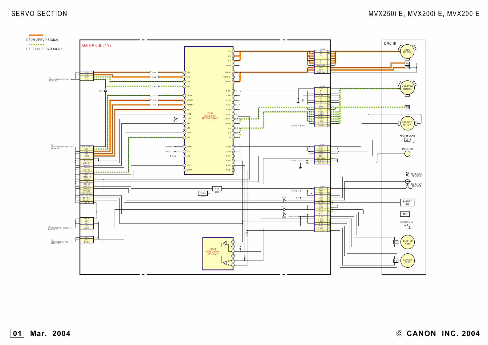
CAPSTAN SERVO SIGNAL
DRUM SERVO SIGNAL
IC301BD6636KV
MOTOR DRIVE
IC300NJM12904R
OPE AMP
PGFG
FG
FG
DRUMMOTOR
CAPSTANMOTOR
MODE SW
LOADINGMOTOR
DEW SENSOR
CASSETTE IN SW
TAKE UPREEL
FG SUPPLYREEL
MIC
SAFETYSW
CN300W 10
1134129657
WVVUU
COIL COMDPGDFG
SENS COM
CN303BOT E 1BOT C 2EOT E 20EOT C 21LED A 14LED K 15
REC PRF 5MIC3 4MIC2
DVDD 2.7V
6MIC1 7C IN 12T IN− 8T IN+ 10
T OUT− 9T OUT+ 11
S IN− 16S IN+ 18
S OUT− 17S OUT+ 19
DVDD 2.7V
DVDD 2.7V
DVDD 2.7V
P 5V
CN302C H− 7W− 8W+ 9
C H+ 10U+ 11U− 12V+ 13V− 14
CFG2 15CFG1 18
U COIL 1U COIL 2W COIL 3W COIL 4V COIL 5V COIL 6
CFG VCC 17
CN3016712
DEW+ 8MSW SENS 5MSW VCC 4MSW VSS 3
28 D.VM
29 D.VS
60 C.VM
15 C.FGSMT
16 D.PGSMT
21 D.FGSMT
30 D.EC
40 L.FRB
41 L.REF
57 D.PS
58 C.PS
59 C.FBR
62 C.EC
61 C.VS
37
35
34
33D.COM
D.U
D.V
D.W
3
1
2
7
6
5
20
19
18D.FGIN−
D.FGPGIN+
D.PGIN−
12C.HW−
11C.HW+
10C.HU+
9C.HU−
8C.HV+
7C.HV−
44L.REV
42L.FWD
46R.IN1+
47R.IN1−
49R.IN2+
50R.IN2−
2C.U
3C.V
5C.W
D VM
D VS
C VS
CFG
DPG
DFG
CAP VS CNTCFGDPGDFG
DERRLMO FRBLLMO FRBHLODE ONDRUM ONCAP ON
CAP FWDCERR
T REEL FGS REEL FG
DA CFGDEW
MSW ADTAPE TOPTAPE ENDTAPE LED
REC PROOFREEL LED CONT
DA TREELDA SREEL
CAS IN
48 ROUT1
51 ROUT2
D VMD VSC VMC VS
MIC1MIC2MIC3
Q304
Q306
Q301
Q300
Q305
27 UNREGVTR UNREG
22 VCCDVDD 2.7V
45 L.VMP 5V
14C.FGIN−
13C.FGIN+
LOAD (− )LOAD (− )
LOAD (+ )
LOAD (+ )
Q303
BOT DET
Q303
EOT DET
MIC ON
CAS IN
MIC2MIC3
DA CFG
TOAUDIO-VIDEO SECTION-2MAIN P.C.B.
TOPOWER SUPPLY SECTIONMAIN P.C.B.
TOAUDIO-VIDEO SECTION-1MAIN P.C.B.
TOSYSTEM CONTROL SECTIONMAIN P.C.B.
TAPE TOPSENSOR
TAPE ENDSENSOR
DMC I I IMAIN P.C.B. (4/7)
SERVO SECTION
CANON INC. 2004C01 Mar. 2004
MVX250i E, MVX200i E, MVX200 E

USB SIGNAL ANALOG VIDEO SIGNAL
IC2301 (3/4)MB87M4541BGL
VIC4
E1 A0
C2
A2
B5
A5
C5
D5
B6
A6
C6
D6
E6
B2
C3
D4 A19
D3 NC3
F1 CE
G1 OE
A4 WE
B4 RESET
D1
C1
A1
B1
D2
IC2300MX29LV160ABXEI
FLASH
E2DO0
H2
E3
H3
H4
E4
H5
E5
F2
G2
F3
G3
F4
G5
F5
G6DO15
EDREQ/PIO
EDACK/PIO
SCS(9)/PIO
EXT RDY1/PI
XECS(1)/PIO
XEWRL
SI(3)/PIO
EDATA (0)
EDATA (15)
XE
CS
(0)
XE
RD
XE
WR
U
TRS
T
XR
ES
ET
D(4
)/P
IO
AA
7
AB11
AA11
X11
AC10
AB10
AA10
Y10
X10
AC9
AB9
AA9
Y9
X9
AC8
AB8
AA8
Y7
X7
AC
6
AB
6
AA
6
AC
5
AB
5
AA
5
AB
4
AA
4
AC
3
AB
3
AC
2
AC
1
AB
1
AB
2
AA
1
AA
2
AA
3
Z1 W5
Y3
EA
DD
R (
22)
T6
X1
X12
V5XECS(4)/PIOW1
SCS(5)/PIOA5
SCS(6)/PIOF9
CDATA(5)/PIOP5
CLAMP PWMB12
VRH2B19
ACC PWMA12
C INF17
Y INC18
COMP INB20
VRH1E18
AGC PWMC12
AIN13AC14
CDATA(6)/PIOR1
CDATA(4)/PIOP3
CDATE(7)/PIOR3
BYPASSE15
C FBA19
Y FBC16
COMP FBE16
C OB17
Y OA18
COMP OB18
UNT CLKI/PIOF7
D(5
)/P
IOX
21
TDIM24
W5
B7
E10
Y1
W6
AA
12
N20V2
AC
25D
(4)/
PIO
X23A1
X2
B11 F8
TMS
SO
UN
D
AB
15A
IN9
E1
PIO
(5)
AB
17A
IN1
Y16
SH
OE
ID
1
SH
OE
ID
2
SH
OE
ON
SI
VD
HG
L V
L
HP
MU
TE
XP
DI
RE
C M
UTE
AIF
SC
LK
AIF
CS
HP
ON
AIF
SO
LPS
/PIO
XE
CS
(2)/
PIO
SC
LK(2
)/P
IO
SC
S(3
)/P
IO
M25
TCK
N25
AM
CK
X24
SO
(2)/
PIO
B10
EA
DD
R (
0)
KEY AD3DIAL-CW
DIAL-CCWDC J DET
CHAGE LEDRMC IN
EJECT SWXRESET
MIC2MIC3
DA CFG
VTR ON IC3201SHOE ID1SHOE ID2SHOE ON
ST VDHGL VL
EADDR (0)
RDY
XECS1
XEWRL
XDREQ
XDACK
USB FS EN
MACS XRST
EADDR (6)
EADDR (7)
EADDR (8)
EADDR (9)
EADDR (10)
EADDR (11)
EADDR (12)
EADDR (13)
EADDR (14)
EADDR (15)
EADDR (16)
EADDR (17)
EADDR (18)
EADDR (19)
EADDR (20)
EADDR (1)
EADDR (2)
EADDR (3)
EADDR (4)
EADDR (5)
TOCAMERA SECTION-3MAIN P.C.B.
EDATA (0)
EDATA (1)
EDATA (2)
EDATA (3)
EDATA (4)
EDATA (5)
EDATA (6)
EDATA (7)
EDATA (8)
EDATA (9)
EDATA (10)
EDATA (11)
EDATA (12)
EDATA (13)
EDATA (14)
EDATA (15)
RDYXECS1XEWRLXDREQXDACK
USB FS ENMACS XRSTMACS TDO
TCKTMS
EDATA (0) to (15)EADDR (0) to (22)
XERDXEWRU
TRST
CN2101
TDITMSTCKTDOV I /OTRSTMIC2MIC3
VTR ON IC3201
CN2900B9B8A7
B10A1B7B5B6B3
VTR UNREGAVDD 2.7V
P5VD−D+
VBUSAV DET
CAM LEDV I /O/HP R
AV RAV L/HP LP GY OUTY GY OUT
RMC INCHARGE LED
DC J SW
269
2117152078532
1210242523
TOSYSTEM CONTROL SECTIONMAIN P.C.B.
TOJACK1,2 SECTIONJACK1 P.C.B.CN51
CN2102
S DETY I /OC I /O
EJECT SWKEY AD3
DIAL-CCWDIAL-CW
762
10131211
CN1100
DA CFGP GY OUTY GY OUT
AV RAV L/HP LV I /O/HP R
SOUNDAIF CSAMCK
HP MUTEXPDI
REC MUTEAIF SCLK
AIF SOHP ON
B18B29B31A60A59A58A46A39A36A45A41A42A40A38A47
TOJACK1,2 SECTIONJACK2 P.C.B.CN91
N.C
TOCAMERA SECTION-1CAV P.C.B.CN1001
TOCAMERA SECTION-2CAV P.C.B.CN1001
TOPOWER SUPPLY SECTIONMAIN P.C.B.
TOSERVO SECTIONMAIN P.C.B.
D−D+
TO CAMERA SECTION-3MAIN P.C.B.
Q3501
Q3503
Q2313
Q3504
Q2312
Q2310
Q2311
WIDE DET
LETTER CONT
WIDE CONT
LINE IN
Q2308
VTR UNREGAVDD2.7VP5V
AVDD2.7V
HA4.7V
Q2309
AVDD1.4V
75Ω
Q2305
75Ω
Q2306
75Ω
Q2307
FROMAUDIO-VIDEO SECTION-2IC2301 (4/4)
MAIN P.C.B. (5/7)
ELURA70 AELURA65 AMVX250i EDM-FV M100ONLY
AUDIO-VIDEO SECTION-1
CANON INC. 2004C01 Mar. 2004
MVX250i E, MVX200i E, MVX200 E

DRUM SERVO SIGNAL CAPSTAN SERVO SIGNALDIGITAL (VIDEO+AUDIO SIGNAL)DIGITAL DV SIGNAL
TOAUDIO-VIDEO SECTION–1IC2301 (3/4)
VIDEO SIGNAL
AUDIO SIGNALTOCAMERA SECTION–4IC2301 (2/4)
NC
1
39
38
37
19
18
17
16
15
PIO(9)
PIO(8)
SCS(3)/PIO
PIO(7)
BRQ/PIO
TCLK/PI
BGRNTX/PIO
PWM(5)/PIO
PWM(7)/PIO
PWM(6)/PIO
AIN14
AIN15
AIN10
AIN11
AIN12
RFGT/PI
RFGS/PI
PWMD
PWMC
CFG
DPG
DFG
CAPDIR/PIO
D(6)/PIO
EADDR(8)/PIO
20
21
35
22
34
33
32
31
30
29
26
25
24
23
53
51
50
48
47
45
44
42
13
11
10
8
7
5
4
2
VD
HD
OSD I(0)/PI
OSD I(1)/PI
DOTCLK/PIO
D(0)/PIO
D(1)/PIO
D(2)/PIO
CTL(1)/PIO
SYSCLK/PIO
AIN12
XESC(3)/PIO
XEINT2/PI
PIO(6)
SCS(0)/PIO
UAT CLKO/PIO
TX/PIO
RX/PIO
XDEBEN
DEBUD
DEBDD
DEBCLK
PIO(4)
SO(1)/PIO
SCLK(1)/PIO
SCLK(0)/PIO
SO(0)/PIO
3
49
43
27
14
9
IC2302EM668165TS-7G
SDRAM
IC2301(4/4)MB87M4541BGL
VIC4
K21
K20
J23
J20
AB19
AA18
AC20
AB20
N21
R25
N24
N23
P25
W20
AB25
AA24
Y21
AB24
AA16
X5
U6
H6
E7
A3
C6
B3
R6
R5
T2
T1
H5
F11
F12
A10
A9
X25
A14
U20
U21
V24
T21
K25
AA22
H25
H24
H26
H21
F21
F23
F24
F25
G20
G21
G25
H20
E19
F19
C20
E20
C21
A22
B22
C22
A23
B23
A24
A25
B24
B25
E24
E25
D24
D23
C23
C24
D25
E23
G3
D1
B5
E2
W3
E3
V6
B2
E6
A2
AA14
AB14
AA15
AC15
Y14
P21
R23
R24
R20
U25
R21
T24
P24
AA23
X8
U24
U23
C13
L24
V25
B13
F14
A13
F13
2
17
21
1
6
34
32
35
3029 13 232226258281211
42
43
45
46
36 385
MAIN P.C.B. (6/7)
SDRAM2.7V
VDDQ1
VDDQ4
VDDQ3
VDD3
VDD2
VDDQ2
VDD1
ADDR (13)
ADDR (12)
ADDR (11)
ADDR (10)
ADDR (9)
ADDR (8)
ADDR (7)
ADDR (6)
ADDR (5)
ADDR (4)
ADDR (3)
ADDR (2)
ADDR (1)
ADDR (0)
MDATA (14)
MDATA (15)
MDATA (13)
MDATA (12)
MDATA (11)
MDATA (10)
MDATA (9)
MDATA (8)
MDATA (7)
MDATA (6)
MDATA (5)
MDATA (4)
MDATA (3)
MDATA (2)
MDATA (1)
MDATA (0)
UDQM
CLK
CKE
/CS
/RAS
/CAS
/WE
LDQM
DQMU
MCLK
CKE
XCS
XRAS
XCAS
XWE
DQML
BA0
BA1
A11
A10/AP
A9
A8
A7
A6
A5
A4
A3
A2
A1
A0
DQ15
DQ14
DQ13
DQ12
DQ11
DQ10
DQ9
DQ8
DQ7
DQ6
DQ5
DQ4
DQ3
DQ2
DQ1
DQ0
DQMU
MCLK
CKE
XCS
XRAS
XCAS
XWE
DQML
ADDR (13)
ADDR (12)
ADDR (11)
ADDR (10)
ADDR (9)
ADDR (8)
ADDR (7)
ADDR (6)
ADDR (5)
ADDR (4)
ADDR (3)
ADDR (2)
ADDR (1)
ADDR (0)
MDATA (15)
MDATA (14)
MDATA (13)
MDATA (12)
MDATA (11)
MDATA (10)
MDATA (9)
MDATA (8)
MDATA (7)
MDATA (6)
MDATA (5)
MDATA (4)
MDATA (3)
MDATA (2)
MDATA (1)
MDATA (0)
XTPB
TPB
XTPA
TPA
H1B2
CN2000H1A
3
H2A 5H2B 6
CH-1HEAD
DRUMUNIT
CH-2HEAD
CN2102TOJACK 1,2 SECTIONJACK2 P.C.B.CN91
TOSYSTEM CONTROL SECTIONMAIN P.C.B.
GD
H C
ON
T
EQ
CO
NT
GD
L C
ON
T
RA
GC
RA
PC
EQ
FC
RC
LK
XR
CLK
RA
FC
UTI
L S
WP
(0)
UTI
L S
WP
(2)
UTI
L S
WP
(1)
RA
GC
RA
PC
UTI
L S
WP
(3)
RC
LK
XR
CLK
UTI
L S
WP
(4)
UTIL SWP(5)
REC H
SWP
PBRF
CTL(0)/PIO
XRDAT
PB H
RDAT H1A
H1B
H2A
H2B
XR
CLK
RC
LK
RA
FC
RA
PC
RA
GC
EQ
FC
EQ
CO
NT
GD
L C
ON
T
GD
H C
ON
T
Q2000
XTPBTPB
XTPATPA
VIC VDVIC HDOSD I0OSD I1
DOT CLKSTOV MODE0STOV MODE1STOV MODE2
CG CSSTOV CS
ZOOM KEYCARD DETCARD PRO
CARD ACCESS LEDVTOS EN
VTOS SCKVTOS DATASTOV DATA
XDEBENDEBUDDEBDD
DEBCLKNTSC XPAL
CG SOCG CLK
VTOS ACTIVEVTOS PC
VTR POW SWMODE RESETCAM POW SW
FCH 0
18191716
VIC VD
VIC HD
OSD I0
OSD I1
DOT CLK
STOV MODE0
STOV MODE1
STOV MODE2
CG CS
STOV CS
ZOOM KEY
CARD DET
CARD PRO
CARD ACCESS LED
VTOS EN
VTOS SCK
VTOS DATA
STOV DATA
XDEBEN
DEBUD
DEBDD
DEBCLK
NTSC XPAL
CG SO
CG CLK
VTOS ACTIVE
VTOS PC
VTR POW SWMODE RESETCAM POW SW
FCH 0SWPPBRF
A3B2A5A6A8
A10
CN2900
CAP VS CNTLMO FRBLLMO FRBHLOAD ONCAP ON
DRUM ONREC PROOF
REEL LED CONTDA CFG
DA SREELDA TREELTAPE TOPTAPE ENDMSW AD
DEWCAS IN
T REEL FGS REEL FG
DERRCERRCFGDPGDFG
CAP FWDTAPE LED
LMO FRBH
LMO FRBL
LOAD ON
CAP ON
DRUM ON
REC PROOF
REEL LED CONT
DA CFG
DA SREEL
DA TREEL
TAPE TOP
TAPE END
MSW AD
DEW
CAS IN
T REEL FG
S REEL FG
DERR
CERR
CFG
DPG
DFG
CAP FWD
TAPE LED
CAP VS CNT
TOSERVO SECTIONMAIN P.C.B.
HA 4.7VHA 3.3V
REC CONT RECON
EPH
PB ON
IC2000LD502W
VRP2
EQ VCO
GCA
GDL
AUDIO-VIDEO SECTION-2
CANON INC. 2004C01 Mar. 2004
MVX250i E,MVX200i E,MVX200 E

CAPSTAN SERVO SIGNAL
DRUM SERVO SIGNAL
27
3446
50
43
53
40
56
5
64
11
62
37
57
21
6022
15
6116
28
29
30
31
33
VCC
IC3201MB3881DC/DC
CONVERTER5 V IN 4V OUT
IC3203TK11147CS
4.7V REGULATOR
MAIN P.C.B.(7/7)
FU3201
FU3205
FU3202
FU3203FU1810
OSC
CH1
CH2
CH3
CH4
2
1 3
45
Q32041.4V (CH1)
2
1 3
45
Q32032.7V (CH2)
2
1 3
45
Q32053V (CH3)
CH8
CH7
2
1 3
45
Q3206P5V (CH4)
CH5
2
1 3
45
Q3207DRUM VS (CH5)
CH6
2
1 3
45
Q3208CAP VS (CH6)
DVDD 1.4V
AVDD 1.4V
MACS 1.4V
VTR UNREG
DVDD 3V
HA 4.7V
AA 4.7V
LCD 5V
P 5V
CCD 15V
CCD −7V
CAM 3V
HA 3V
SDRAM 2.7V
AVDD 2.7V
DIF 2.7V
DVDD 2.7V
LCD 2.7V
M SDRAM 2.7V
AA 2.7V
ON/OFFCONT.
CH1,3,4,8
CH2
CH5,6
CH7
D VMC VM
C VSD VS
TO SERVO SECTIONMAIN P.C.B.
ADV/EXT MIC RADV MIC LST STSP
SHOE ID1ST VDHGL VL
SHOE ID2SHOE ON TO
AUDIO-VIDEO SECTION-1MAIN P.C.B.
TO CAMERA SECTION-3MAIN P.C.B.
TO SYSTEM CONTROL SECTION-3MAIN P.C.B.
TOSEEVO SECTIONMAIN P.C.B.
4
3
2
1
5
6
7
8
T3202
D3203
Q3202
D3205
LCD 8.5V
D3202
DC +DC −
DC V DETA/D IA/D V
BATT INFO ADCAM ONCHARGE
INIT CHARGE1VTR ON
CN3201
Q1814
Q1815
Q1812
Q1813
Q1801
Q3209
Q321021
BATT INFO ADBATT −BATT −BATT +BATT +
CN3202
VTR ON IC3201
31245
TOJACK1,2 SECTIONJACK1 P.C.B.CN3211
TOSYSTEM CONTROL SECTIONMAIN P.C.B.
TOBATTERY TERMIANL
ADV/EXT MIC RADV MIC L
ID-2ST STSP
ST VDHGLID-1
SHOE UNREGSHOE UNREG
CN8911211987621
TOSHOE CONNECTOR
TOAUDIO-VIDEO SECTION-1MAIN P.C.B.
Q3201
14
12 13 7
2 3
8
15
VCC
DSC POWERSAVE
OUTPUTDRIVE
2
4
3 1
LPF
LPF
LPF
LPF
LPF
LPF
LPF
IC1810MB3833A-E1
CHARGEIC
IC1811MM3012XNOPE AMP
ELURA70 AELURA65 AMVX250i EDM-FV M100ONLY
POWER SUPPLY SECTION
C CANON INC. 200401 Mar. 2004
MVX250i E, MVX200i E, MVX200 E

DATA COMMUNICATION
TOSYSTEM CONTROL SECTIONKEY P.C.B.CN102
TOLCD DETECT FPC
LCSECSSO
SOCLK
VTR UNREG
LCD 2.7V
LCD 2.7V
LCD 8.5V
LCD 5V
1
8VCC2
3
4
E CS
CLK
SO
SO
LCD 2.7V
LCD 5V
LCD 2.7V
VCC5V
Q901
Q902
Q903
1ON
3
WP4201
WP4202
4
1
1 5 2
346
23 5
4
5
DI
DO
CONTROL
VTR UNREG
Q4201SWITCH
Q4204
VTR UNREG
VTR UNREG
Q4202DRIVER
Q4203
BACK LIGHT
R/R-Y
IC902CXM3009TQLCD DRIVE
6
26
47
46
42
38
37
3618 29
5
41
43
13
14
15
16
17
19
20
21
22
23
8
7
44
45
33
35
34
GREEN
CN902
BLUEVSTVCKEN
2
1124
7
623
89
12
13141920
2122
35
RED 4VDD 18
L CS
CLK
SO
SEN
G/Y
B/B-Y
SYNCIN
SCK
SDAT
VC
C2
VD
D2
VD
D1
VCC1-1
DA
OU
TB
L C
ON
TRO
L
PD
F
VCC1-2
VCK
24VST
EN
G OUT
R OUT
B OUT
DWN
XSTB
PCG
HST
WIDE
CHK2
CHK1
RGT
REF
COM-DC
PSIG OUT
DWNXSTBY
PCGHST
WIDEHCK2HCK1RGTREFCOMCS
PSIG
LCD UNIT
CS
SK
2
3
4
1
5
7
T4201
6
VCC 5V
CN901
CN903
VTR UNREGVTR UNREGVTR UNREG
LCD 8.5VLCD 5V
LCD 2.7VLCD 2.7VLCD ON
LCD BL ONPANEL RPANEL GPANEL BC SYNCLCD CS
LCD EEP CSLCD EEP SOUTLCD EEP SCKLCD EEP SIN1PANEL BT SWPANEL BT SW
456
1415161787
24232218131211109
2627
PANEL BT SWLCD2.7V
13
LCD 8.5V
Q904
IC901BR9010RFV-W
EEPROM
IC4201R1223N152H
DC/DCCONVERTER
CONTROL
LCD P.C.B.
LCD
LCD P.C.B. SECTION
CANON INC. 2004C01 Mar. 2004
MVX250i E, MVX200i E, MVX200 E

USB SIGNAL ANALOG AUDIO SIGNALANALOG VIDEO SIGNAL
1 VO
2 VCC
Y C
G1 G2
2 OUT 1VCCIC1601
ENC-03MAP SENSOR GYRO
2 OUT 1VCCIC1602
ENC-03MBY SENSOR GYRO
REMOTE CONTROLER
CN42
LED61
LED62
EXT LADV/EXT MIC R
EXT P DETINT MIC RINT MIC L
INT MIC RINT MIC L
13468
CN43
24
CN81
CN3212
AV JACK
DC JACK
CN41
MIC JACK
VBUS (+5V)D−D+
CN3551123
RU71
TOAUDIO-VIDEO SECTION-2MAIN P.C.B.CN2102
USB JACK
P5VP5V
VTR UNREG
CN91
TPBXTPBXTPATPA
KEY AD3DIAL CCWDIAL CW
EJECT SWS DETY I /OC I /O
234589
1011141519
DV JACK
S JACK
XTPBTPB
XTPATPA
CN111234
CN31
AVDD2.7V
AVDD2.7V
TOCAMERA SECTION-1CAV P.C.B.CN701
TOMIC UNIT
DC+DC−
CN3211
12
TOPOWER SUPPLY SECTIONMAIN P.C.B.CN3201
CN51
CHAGE LEDRMC IN
DC J SWVBUS
D−D+
P GY OUTY GY OUTCAM LEDAV DET
V I /O/HP RAV R
AV L/HP L
2347
101215171920222425
TOAUDIO-VIDEO SECTION-1MAIN P.C.B.CN2101
TOAUDIO-VIDEO SECTION-1MAIN P.C.B.CN2102
SW23
SW22
SW21
PUSH
MENU
EJECT ON
JACK1 P.C.B.
ELURA70 AELURA65 AMVX250i EDM-FV M100ONLY
ELURA70 AELURA65 AMVX250i EDM-FV M100ONLY
JACK1,2 SECTION
CANON INC. 2004C01 Mar. 2004
MVX250i E, MVX200i E, MVX200 E