
Canon i860, i865 SM - Printer1.Blogspot
35
i860 SERVICE MANUAL Canon
-
Upload
roger-burford -
Category
Documents
-
view
47 -
download
5
Transcript of Canon i860, i865 SM - Printer1.Blogspot
i860
SERVICEMANUAL
Canon

PIXUS 860i i860 i865 SERVICE MANUAL Revision 0
QY8-1391-000 COPYRIGHT 2003 CANON INC. CANON PIXUS 860i / i860 / i865 082003 XX 0.00-0

Scope This manual has been issued by Canon Inc., to provide the service technicians of this product with the information necessary for qualified persons to learn technical theory, installation, maintenance, and repair of products. The manual covers information applicable in all regions where the product is sold. For this reason, it may contain information that is not applicable to your region.
Revision
This manual could include technical inaccuracies or typographical errors due to improvements or changes made to the product. When changes are made to the contents of the manual, Canon will release technical information when necessary. When substantial changes are made to the contents of the manual, Canon will issue a revised edition.
The following do not apply if they do not conform to the laws and regulations of the region where the manual or product is used: Trademarks
Product and brand names appearing in this manual are registered trademarks or trademarks of the respective holders.
Copyright
All rights reserved. No parts of this manual may be reproduced in any form or by any means or translated into another language without the written permission of Canon Inc., except in the case of internal business use.
Copyright 2003 by Canon Inc. CANON INC. Inkjet Products Quality Assurance Div. 16-1, Shimonoge 3-chome, Takatsu-ku, Kawasaki, Kanagawa 213-8512, Japan

I. MANUAL OUTLINE This manual consists of the following three parts to provide information necessary to service the i860 and i865: Part 1: Maintenance Information on maintenance and troubleshooting of the i860 and i865 Part 2: Technical Reference New technology and technical information such as FAQ’s (Frequently Asked Questions) of the i860 and i865 Part 3: Appendix Block diagrams and pin layouts of the i860 and i865 Reference: This manual does not provide sufficient information of disassembly and reassembly procedures. Refer to the graphics in the separate Parts Catalog.

II. TABLE OF CONTENTS Page Part 1: MAINTENANCE 1-1 1. MAINTENANCE 1-1 1.1 Adjustment, Periodic Maintenance, Periodic Replacement Parts, and Replacement
Consumables by Service Engineer 1-2 1.2 Customer Maintenance 1-2 1.3 Product Life 1-3 1.4 Special Tools 1-3 1.5 Serial Number Location 1-4 2. LIST OF ERROR DISPLAY / INDICATION 1-4 2.1 Operator Call Errors (by LED Blinking in Orange) 1-5 2.2 Service Call Errors (by LED Blinking in Orange and Green Alternately, or Lit in
Orange) 1-6 2.3 Warnings 1-6 2.4 Troubleshooting by Symptom 1-8 3. REPAIR 1-8 3.1 Notes on Service Part Replacement (and Disassembling / Reassembling) 1-10 3.2 Special Notes on Repair Servicing 1-12 3.3 Adjustment / Settings (1) Paper feed motor adjustment (2) Gear phase adjustment (3) Grease application (4) Waste ink counter setting (5) User mode (6) Service mode EEPROM initialization, EEPROM settings, Waste ink counter reset Service test print, EEPROM information print (7) Flash ROM upgrade 1-19 3.4 Verification Items (1) Service test print (2) EEPROM information print 1-22 4. PRINTER TRANSPORTATION METHOD Part 2: TECHNICAL REFERENCE 2-1 1. NEW TECHNOLOGIES 2-4 2. CLEANING MODE AND AMOUNT OF INK PURGED 2-6 3. FAQ (Specific Problems and Solutions) Part 3: APPENDIX 3-1 1. BLOCK DIAGRAM 3-2 2. CONNECTOR LOCATION AND PIN LAYOUT 3-2 2.1 Logic Board Ass’y 3-6 2.2 Carriage Board (Print Head Connector)

Part 1 MAINTENANCE

1. MAINTENANCE 1.1 Adjustment, Periodic Maintenance, Periodic Replacement Parts, and
Replacement Consumables by Service Engineer (1) Adjustment
Adjustment Timing Purpose Tool Approx. time
EEPROM initialization (EEPROM settings)
At logic board ass’y replacement
To initialize settings other than the following: - USB serial number - Destination setting - Waste ink counter - Media sensor correction
value - CD-R correction value
None. 1 min.
Destination settings (EEPROM settings)
At logic board ass’y replacement
To set the destination. None. 1 min.
Waste ink counter resetting
- At bottom case unit replacement
- At ink absorber (QC1-2232 / 2233 / 2234 / 2235 / 2236) replacement
To reset the waste ink counter.
None. 1 min.
Media sensor correction*1
(EEPROM settings)
- At logic board ass’y replacement
- At sheet feeder unit replacement
To correct the media sensor.
Calibration media kit (QY9-0064)*2
2 min.
CD-R sensor / automatic print head alignment sensor correction (EEPROM settings)
- At logic board ass’y replacement
- At carriage unit replacement
To correct the CD-R and automatic print head alignment sensor.
None. (Correction performed through service test print)
1 min.
Print head alignment - At print head replacement
- At logic board ass’y replacement
To ensure accurate dot placement.
- None. (printer buttons)- Computer
(settings via the printer driver)
2 min.
Paper feed motor position adjustment*3
At paper feed motor unit replacement
To adjust the belt tension. (Position the paper feed motor so that the belt is stretched tight.)
None. 2 min.
Grease application - At carriage unit replacement
- At paper guide flapper ass’y (QL2-0341) replacement
- At lift cam base’s (QL2-0340) gear replacement
- At lift cam shaft unit (QM2-0593) replacement
- To maintain sliding properties of the carriage, carriage shaft, paper guide flapper, and lift cam shaft.
- To protect the lift cam base gear.
- FLOIL KG-107A (QY9-0057)
- MOLYKOTE PG641 (CK-0562)
2 min.
Note: DO NOT loosen the red screws on both sides of the main chassis, securing the carriage shaft positioning. *1: Media sensor correction This operation adjusts the correction value of the media sensor, installed in the sheet feeder unit, to the
EEPROM of the logic board ass’y. The adjustment is required when the sheet feeder unit or the logic board ass’y is replaced, and values are automatically determined via use of calibration media kit (QY9-0064).
*2: Calibration media kit The service tool for media sensor correction, consisting of 10 sheets of the reference plain paper, and 1
1 - 1

sheet of the reference white PET paper. *3: Red screws of paper feed motor The red screws securing the paper feed motor may be loosened only at replacement of the paper feed motor
unit. (2) Periodic maintenance No periodic maintenance is necessary. (3) Periodic replacement parts There are no parts in this printer that require periodic replacement by a service engineer. (4) Replacement consumables There are no consumables that require replacement by a service engineer.
1.2 Customer Maintenance
Adjustment Timing Purpose Tool Approx. time
Print head alignment At print head replacement.
To ensure accurate dot placement.
- Printer buttons - Computer (settings
via the printer driver)
3 min.
Print head cleaning When print quality is not satisfying.
To improve nozzle conditions.
- Printer buttons - Computer (settings
via the printer driver)
30 sec. to 1 min.
Print head deep cleaning When print quality is not satisfying, and not improved by print head cleaning.
To improve nozzle conditions.
Computer (settings via the printer driver)
1 to 1.5 min.
Ink tank replacement When an ink tank becomes empty. (No ink error)
----- ----- 2 min.
Paper feed roller cleaning
When paper does not feed properly.
To clean the paper feed rollers.
Printer buttons 2 min.
CD-R print position adjustment
At CD-R printing, when necessary
To correct CD-R print position
Computer (application software)
5 min.
1.3 Product Life (1) Printer The value from (i) to (iv), whatever comes first. (i) 10,000 pages of color printing, or 30,000 pages of black printing - Color: 7.5% duty per color pattern printing, A4 - Black: 1,500 character pattern printing (ii) 1,200 disks of CD-R or DVD-R printing - On a basis of monthly print volume of approx. 20 disks (iii) 5,000 pages of printing using the photo paper tray - On a basis of monthly print volume of approx. 83 pages (iv) 5 years of use
1 - 2
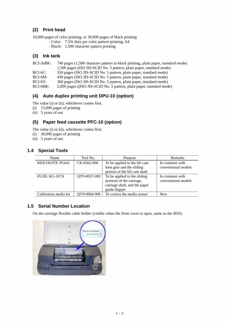
(2) Print head 10,000 pages of color printing, or 30,000 pages of black printing - Color: 7.5% duty per color pattern printing, A4 - Black: 1,500 character pattern printing (3) Ink tank BCI-3eBK: 740 pages (1,500 character pattern in black printing, plain paper, standard mode) 1,500 pages (ISO JIS-SCID No. 5 pattern, plain paper, standard mode) BCI-6C: 550 pages (ISO JIS-SCID No. 5 pattern, plain paper, standard mode) BCI-6M: 430 pages (ISO JIS-SCID No. 5 pattern, plain paper, standard mode) BCI-6Y: 360 pages (ISO JIS-SCID No. 5 pattern, plain paper, standard mode) BCI-6BK: 2,000 pages ((ISO JIS-SCID No. 5 pattern, plain paper, standard mode) (4) Auto duplex printing unit DPU-10 (option) The value (i) or (ii), whichever comes first. (i) 15,000 pages of printing (ii) 5 years of use (5) Paper feed cassette PFC-10 (option) The value (i) or (ii), whichever comes first. (i) 30,000 pages of printing (ii) 5 years of use
1.4 Special Tools Name Tool No. Purpose Remarks
MOLYKOTE PG641 CK-0562-000 To be applied to the lift cam base gear and the sliding portion of the lift cam shaft
In common with conventional models
FLOIL KG-107A QY9-0057-000 To be applied to the sliding portions of the carriage, carriage shaft, and the paper guide flapper
In common with conventional models
Calibration media kit QY9-0064-000 To correct the media sensor New
1.5 Serial Number Location On the carriage flexible cable holder (visible when the front cover is open, same as the i850).
1 - 3

2. LIST OF ERROR DISPLAY / INDICATION Errors are indicated by the LED, and warnings are displayed on the monitor of the computer connected to the printer.
2.1 Operator Call Errors (by LED Blinking in Orange) LED
blinking in orange
Error Solution Remarks
No paper. (ASF) [1000] Set the paper in the ASF, and press the Resume/Cancel button.
No CD-R tray. [1001]*1 Set the CD-R tray, and press the Resume/Cancel button.
No paper in the photo paper tray. [1004]
Set the paper in the photo paper tray, and press the Resume/Cancel button.
2 times
No paper in the paper feed cassette. [1003]*2
Set the paper in the paper feed cassette, and press the Resume/Cancel button.
Paper jam. [1300] Paper jam in the auto duplex printing unit. [1304]*3
3 times
Paper jam in the paper feed cassette. [1303]*2
Remove the jammed paper, and press the Resume/Cancel button.
4 times No ink. [1601/1602/1611/1612/1613]
Replace the empty ink tank(s), or press the Resume/Cancel button.
Pressing the Resume/Cancel button will exit the error without ink tank replacement, however, ink may run out during printing.
5 times The print head is not installed [1401], or it is not properly installed (EEPROM data of the print head is faulty) [1403/1405].
Install the print head properly, and close the front cover. Or, with the print head installed, turn the printer off and on.
No CD-R tray feeder (during CD-R printing). [1850/1855]
Set the CD-R tray and tray feeder properly, and press the Resume/Cancel button.
6 times*1
Presence of the CD-R tray feeder (during paper printing). [1851/1856]
Remove the CD-R tray feeder, and press the Resume/Cancel button.
7 times*1 No CD-R or DVD-R. [1002] After setting a CD-R or DVD-R in the tray, set the tray in the tray feeder, and press the Resume/Cancel button.
8 times Warning: The waste ink absorber becomes almost full (approx. 95% of the maximum capacity).
Pressing the Resume/Cancel button will exit the error, and enable printing. In repair servicing, replace the bottom case unit (QM2-0586), or 5-item set of the ink absorbers (QC1-2232/2233/2234/2235/2236).
The service call error, indicating the waste ink absorber is full, is likely to occur soon.
9 times The connected digital camera or digital video camera does not support Camera Direct Printing. [2001]
After removing the cable between the camera and the printer, press the Resume/Cancel button, and re-connect the cable.
When connected to a Direct Print supported camera, the green LED blinks 2 times.
1 - 4

(Operator Call Errors - cont’d -) LED
blinking in orange
Error Solution Remarks
No auto duplex printing unit. [1860]
Set the auto duplex printing unit, and press the Resume/Cancel button.
10 times*3
Automatic duplex printing cannot be performed (paper size not supported). [1310]
Set an automatic duplex printing supported size of paper, and press the Resume/Cancel button.
11 times Failed in automatic print head alignment. [2500]
Press the Resume/Cancel button, and after confirming the following, perform print head alignment again: - Set an appropriate type and size
of paper (plain paper, A4 or letter).
- Check that the nozzle check pattern is properly printed (all ink ejected, no faint printing).
*1: Only for the model supporting CD-R printing (i865 / PIXUS 860i). *2: Only when the paper feed cassette PFC-10 (optional unit) is attached. *3: Only when the auto duplex printing unit DPU-10 (optional unit) is attached.
2.2 Service Call Errors (by LED Blinking in Orange and Green Alternately, or Lit in Orange)
LED alternate blinking
in orange and green
Error Solution (Replacement of listed parts, which are likely to be faulty)
2 times Carriage error [5100] - Carriage unit (QM2-0599) - Timing slit strip film (QA4-1053) - Logic board ass’y (QM2-0766/QM2-0767)*1
- Carriage motor (QK1-0175) 3 times Paper feed error [6000] - Timing sensor unit (QM2-0596)
- Timing slit disk film (QC1-2484) - Feed roller ass’y (QF4-0155) - Platen unit (QM2-0627/QM2-0634) - Logic board ass’y (QM2-0766/QM2-0767)*1
- Paper feed motor unit (QM2-0810) 4 times Purge unit error [5C00] - Purge unit (QM2-0600)
- Logic board ass’y (QM2-0766/QM2-0767)*1
6 times Internal temperature error [5400]
- Logic board ass’y (QM2-0766/QM2-0767)*1
7 times Waste ink absorber full [5B00]
- Ink absorbers (QC1-2232/2233/2234/2235/2236) - Bottom case unit (QM2-0586)*4
8 times Print head temperature rise error [5200]
- Print head (QY6-0049) - Logic board ass’y (QM2-0766/QM2-0767)*1
9 times EEPROM error [6800] - Logic board ass’y (QM2-0766/QM2-0767)*1
10 times*2 Carriage lift mechanism error [5110]
- Lift cam shaft unit (QM2-0593) - Photo interrupter (WG8-5571) - Sheet feeder unit (QM2-0589) - Logic board ass’y (QM2-0766/QM2-0767)*1
11 times*3 Paper feed cassette error [5900]
- Paper feed cassette PFC-10 (option) - Logic board ass’y (QM2-0766/QM2-0767)*1
- Bottom case unit (QM2-0586)*4
12 times Media sensor error [8000]
- Sheet feeder unit (QM2-0589)
1 - 5

(Service Call Errors - cont’d -) LED
alternate blinking in orange and
green
Error Solution (Replacement of listed parts, which are likely to be faulty)
13 times USB Host VBUS overcurrent [9000]
- Logic board ass’y (QM2-0766/QM2-0767)*1
15 times Other hardware error [6500]
- Logic board ass’y (QM2-0766/QM2-0767)*1
Continuous alternate blinking
Flash ROM error - Logic board ass’y (QM2-0766/QM2-0767)*1
Lights in orange RAM error - Logic board ass’y (QM2-0766/QM2-0767)*1
*1: Before replacement of the logic board ass’y, check the waste ink amount (by service test print or EEPROM information print). If the waste ink amount is 7% or more, also replace the bottom case unit (QM2-0586) or the 5-item set of the ink absorbers (QC1-2232/2233/2234/2235/2236) when replacing the logic board ass’y. See Section 3.3. Adjustment / Settings, (6) Service mode, for details.
*2: Only for models supporting CD-R printing (i865 / PIXUS 860i). *3: Only when the paper feed cassette PFC-10 (optional unit) is attached. *4: Reset the waste ink counter when replacing the bottom case unit (QM2-0586). See Section 3.3. Adjustment
/ Settings, (6) Service mode, for details.
2.3 Warnings (1) Printer (no LED indications)
Displayed warning Remarks
Low ink of 3eBK, 6C, 6M, 6Y, or 6BK (at detection of no remaining of raw ink)
The status is displayed on the monitor of the computer connected to the printer.
Print head temperature rise warning If the print head temperature is high when the front cover is opened, the warning is displayed*1. When the print head temperature falls, the warning is released.
Protection of excess rise of the print head temperature If the print head temperature exceeds the specified limit, a Wait is inserted during printing,
Presence of the CD-R tray feeder*2 If the CD-R tray feeder is attached when the front cover is opened, the warning is displayed.*1
When the CD-R tray feeder is removed, and the front cover is closed, the warning is released.
*1: If the warning is displayed, the carriage does not move to the ink tank replacement position when the front cover is opened.
*2: Only for models supporting CD-R printing (i865 / PIXUS 860i).
2.4 Troubleshooting by Symptom Symptom Solution Remarks
The power does not turn on. The power turns off immediately after power-on.
Replace the - AC adapter, or - logic board ass’y*1.
The print head is not recognized. The print head does not move to the home position.
Remove and re-install the print head, or replace the - print head, or - logic board ass’y*1.
A strange noise occurs. Remove foreign material, or attach a removed part if any.
Faulty operation
Printing stops mid-way. Replace the logic board ass’y*1.
1 - 6

(Troubleshooting by Symptom - cont’d -) Symptom Solution Remarks
Multiple sheets feed. Replace the - sheet feeder unit, - photo paper tray, or - paper feed cassette.
Paper does not feed. Remove foreign material, or replace the - sheet feeder unit, - photo paper tray, or - paper feed cassette.
Paper feed problems
Paper feeds at an angle. Remove foreign material, adjust the paper guide, or replace the - sheet feeder unit, - photo paper tray, or - paper feed cassette.
No printing, or no color ejected. Replace the - ink tank, - print head*2, - logic board ass’y*1, or - purge unit.
Printing is faint, or white lines appear on printouts even after print head cleaning. Line(s) not included in the print data appears on printouts.
Remove and re-install the print head, or replace the - ink tank, - print head*2, - purge unit, or - logic board ass’y*1.
Paper gets smeared. Feed several sheets of paper, or clean the paper path with cotton swab or cloth.
A part of a line is missing on printouts.
Replace the - ink tank, or - print head*2.
Color hue is incorrect. Replace the - ink tank, or - print head*2, or correct the media sensor.
Printing is incorrect. Replace the logic board ass’y*1. No ejection of black ink. Replace the
- ink tank, or - print head*2.
U
nsatisfactory print quality
Graphic or text is enlarged on printouts.
When enlarged in the carriage movement direction, clean grease or oil off the timing slit strip film, or replace the - timing slit strip film, - carriage unit, or - logic board ass’y*1. When enlarged in the paper feed direction, clean grease or oil off the timing slit strip film, or replace the - timing slit disk film, - timing sensor unit, or - logic board ass’y*1.
*1: Before replacement of the logic board ass’y, check the waste ink amount (by service test print or EEPROM information print). If the waste ink amount is 7% or more, also replace the bottom case unit (QM2-0586) or the 5-item set of the ink absorbers (QC1-2232/2233/2234/2235/2236) when replacing the logic board ass’y. See Section 3.3. Adjustment / Settings, (6) Service mode, for details.
*2: Replace the print head only after the print head deep cleaning is performed 2 times, and when the problem persists.
1 - 7

3. REPAIR 3.1 Notes on Service Part Replacement (and Disassembling / Reassembling)
Service part Notes on replacement*1 Adjustment / settings Operation check
Logic board ass’y (QM2-0766/0767)
- Before removal of the logic board ass’y, remove the power cord, and allow for approx. 1 minute (for discharge of capacitor’s accumulated charges), to prevent damages to the logic board ass’y.
- Before replacement, check the waste ink amount (by service test print or EEPROM information print). If the waste ink amount is 7% or more, also replace the bottom case unit or the ink absorbers when replacing the logic board ass’y. See 3.3. Adjustment / Settings, (6) Service mode, for details.
After replacement: 1. Initialize the EEPROM. 2. Reset the waste ink
counter. 3. Set the destination in
the EEPROM. 4. Correct the media
sensor. 5. Correct the CD-R and
automatic print head alignment sensor.
For details of 1 to 5, see 3.3. Adjustment / Settings, (6) Service mode. 6. Perform the print head
alignment in the user mode.
- EEPROM information print
- Service test print - Printing via parallel
or USB connection- Direct printing
from a digital camera
Bottom case unit (QM2-0586) Ink absorber (QC1-2232/2233/ 2234/2235/2236)
After replacement: 1. Reset the waste ink
counter. See 3.3. Adjustment / Settings, (6) Service mode.
- Service test print
Sheet feeder unit (QM2-0589)
After replacement: 1. Correct the media
sensor. See 3.3. Adjustment / Settings, (6) Service mode.
- Service test print (Confirm media sensor correction.)
Carriage unit (QM2-0599)
At replacement: 1. Apply grease to the
sliding portions. See 3.3. Adjustment / Settings, (3) Grease application.
After replacement: 1. Correct the CD-R and
automatic print head alignment sensor. See 3.3. Adjustment / Settings, (6) Service mode.
2. Perform the print head alignment in the user mode.
- Service test print (Confirm CD-R and automatic print head alignment sensor correction.)
Paper feed motor unit (QM2-0810)
- The red screws securing the paper feed motor are allowed to be loosened. (DO NOT loosen any other red screws.)
At replacement: 1. Adjust the paper feed
motor. See 3.3. Adjustment / Settings, (1) Paper feed motor adjustment.
1 - 8

(Notes on Service Part Replacement and Disassembling / Reassembling - cont’d-)
Service part Notes on replacement*1 Adjustment / settings Operation check
Lift cam shaft unit (QM2-0593)
At replacement: 1. Apply grease to the
sliding portions. See 3.3. Adjustment / Settings, (3) Grease application.
2. Adjust the phase of the lift shaft gear (QC1-2297). See 3.3. Adjustment / Settings, (3) Grease application.
- Service test print
Timing slit strip film (QA4-1053)
Timing slit disk film (QC1-2511)
- Upon contact with the film, wipe the film with ethanol.
- Confirm no grease is on the film. (Wipe off any grease thoroughly with ethanol.)
- Do not bend the film.
After replacement: 1. Perform the print head
alignment in the user mode.
- Service test print
Print head (QY6-0049)
After replacement: 1. Perform the print head
alignment in the user mode.
- Service test print
*1: General notes: - Make sure that the flexible cables and wires in the harness are in the proper position and connected
correctly. See 3.2. Special Notes on Repair Servicing, (1) Flexible cable and harness wiring, connection, for details.
- Do not drop the ferrite core, which may cause damage. - Protect electrical parts from damage due to static electricity. - Before removing a unit, after removing the power cord, allow the printer to sit for approx. 1 minute
(for capacitor discharging to protect the logic board ass’y from damages). - Do not touch the timing slit strip film and timing slit disk film. No grease or abrasion is allowed. - Protect the units from soiled with ink. - Protect the housing from scratches. - Exercise caution with the red screws, as follows: i. The red screws of paper feed motor may be loosened only at replacement of the paper feed
motor unit (DO NOT loosen them in other cases). ii. DO NOT loosen the red screws on both sides of the main chassis, securing the carriage shaft
positioning (they are not adjustable in servicing).
1 - 9

3.2 Special Notes on Repair Servicing (1) Flexible cable and harness wiring, connection Be careful of wiring of the flexible cables and harness. Improper wiring or connection may cause breakage of a line, leading to ignition or emission of smoke.
(I) Panel harness ass’y wiring
(II)
(III)
Panel harness ass’y
(I)
1 - 10

(II) Logic board ass’y (paper feed motor side) wiring
Timing sensor (Paper feed motor unit)
Ink sensor (Platen unit)
Paper feed motor & timing sensor (Paper feed motor unit)
Auto duplex printing PE sensor harness (Option gear unit)
CD-R tray feeder switch(Platen unit)
(III) Logic board ass’y (carriage motor side) wiring
Purge motor harness Purge sensor harness (Purge unit)
1 - 11

3.3 Adjustment / Settings (1) Paper feed motor adjustment Perform the following adjustments when the paper feed motor unit is replaced: 1) When attaching the motor, fasten the screws so that the belt is properly stretched (in the direction
indicated by the blue arrow in the figure below). 2) After replacement, be sure to perform the service test print, and confirm that no strange noise or faulty
print operation (due to dislocation of the belt or gear, or out-of-phase motor, etc.) occurs.
Red screws securing the paper feed motor
Adjust the phase.
Lift shaft gear
Carriage shaft cam R
Note: The red screws securing the paper feed motor may be loosened only at replacement of the
paper feed motor unit. DO NOT loosen them in other cases. (2) Gear phase adjustment In attaching the lift shaft gear (QC1-2297), adjust the phase so that the protrusion of the lift shaft gear (QC1-2297) fits into the recess of the carriage shaft cam R (QC1-2299), as shown in the figure below.
1 - 12

(3) Grease application
20, 22
7 to 17 4, 5, 6
23
12
11
10
97
8
6 4
515
16, 17
13, 14
20, 21
1 (Rear side)
2
3
1 - 13

Paper guide flapper ass’y
18
19
Part name Where to apply grease / oil Grease / oil name Grease / oil amount
Carriage slide plate 1 Carriage unit sliding portion FLOIL KG107 3 drops Carriage shaft 2 Carriage unit sliding portion FLOIL KG107 200 to 400mgShaft clip L / R 3 Carriage shaft sliding portion FLOIL KG107 1 drop each Pressure roller ass’y 4 Lift cam shaft unit sliding portion MOLYKOTE PG641 1 drop
5 Pressure roller ass’y sliding portion (4 locations of the cam) MOLYKOTE PG641 1 drop
x 4 locations Lift cam shaft unit
6 Torsion spring (4 locations) MOLYKOTE PG641Thin film of oil x 4 locations
Bushing (on the lift input gear side) 7 Bushing inner surface MOLYKOTE PG641 1 drop
8 Bushing sliding portion MOLYKOTE PG641 1 drop Lift input gear
9 Gear tooth (2 locations) MOLYKOTE PG641 1 drop x 2 locations
Lift transmission gear (QC1-2294) 10 Larger gear tooth (3 locations),
smaller gear tooth (2 locations) MOLYKOTE PG641 1 drop x 5 locations
Lift transmission gear (QC1-2295) 11 Larger gear tooth (5 locations),
smaller gear tooth (2 locations) MOLYKOTE PG641 1 drop x 7 locations
Lift transmission gear (QC1-2296) 12 Gear tooth (all teeth) MOLYKOTE PG641 2 drops
13 Bushing sliding portion MOLYKOTE PG641 1 drop Lift shaft gear
14 Gear tooth (2 locations) MOLYKOTE PG641 1 drop x 2 locations
Carriage input gear 15 Gear tooth (2 locations) MOLYKOTE PG641 1 drop x 2 locations
16 Cam sliding portion FLOIL KG107 1 drop Carriage shaft cam R
17 Gear tooth (2 locations) MOLYKOTE PG641 1 drop x 2 locations
18 Feed roller ass’y sliding portion FLOIL KG107 2 drops Paper guide flapper ass’y 19 Lift cam shaft unit sliding portion MOLYKOTE PG641 1 drop
20 Carriage shaft sliding portion (3 locations each, on the left and right sides) FLOIL KG107 1 drop
x 6 locations 21 Carriage shaft cam L sliding portion FLOIL KG107 2 drops 22 Carriage shaft cam R sliding portion FLOIL KG107 2 drops
Chassis
23 Lift cam shaft unit bushing (4 locations) FLOIL KG107 1 drop x 4 locations
Note: 1 drop = 9 to 18 mg
1 - 14

(4) Waste ink counter setting When the logic board ass’y is replaced, reset the waste ink counter. In addition, according to the waste ink amount, replace the waste ink absorber (the bottom case unit or the 5-item set of the ink absorbers). The standard amount for waste ink absorber replacement is given in the table below.
Waste ink amount*1 Bottom case unit or 5-item set of ink absorbers replacement
Less than 7% Not required. 7% or more Required.
*1: Check the waste ink amount by service test print or EEPROM information print. (See 3.3. Adjustment / Settings, (5) Service mode, for details.)
(5) User mode
Function Procedures Remarks Print head manual cleaning - Cleaning both black and color:
See “Standalone printer operation” below. - Cleaning black or color separately, or both
black and color: Perform from the printer driver utility.
Print head deep cleaning - Cleaning black or color separately, or both black and color:
Perform from the printer driver utility.
Paper feed roller cleaning See “Standalone printer operation” below. Nozzle check pattern printing See “Standalone printer operation” below. Also available from the
printer driver’s Maintenance tab.
Print head alignment See “Standalone printer operation” below. In Custom Settings of the printer driver’s Maintenance tab, manual print head alignment (by selecting the optimum values) as with the conventional models can be performed.
Print head replacement The print head is replaceable at the same position as for ink tank replacement. (Open the front cover. When the carriage stops at the center, the print head can be replaced.)
<Standalone printer operation> 1) Turn on the printer. 2) Press and hold the Resume/Cancel button until the LED blinks the specified number of times listed in
the table below, and release it. The operation starts.
LED blinking Operation Remarks 1 time Print head manual cleaning 2 times Nozzle check pattern printing Set a sheet of plain paper (A4 or letter) in the ASF. 3 times Paper feed roller cleaning 4 times Automatic print head alignment Set a sheet of plain paper (A4 or letter) in the ASF. 5 times or more Unspecified
1 - 15

(6) Service mode Function Procedures Remarks
Service test print - Destination - ROM version - Waste ink amount - Number of pages printed - CD-R / automatic print
head alignment sensor correction
See “Service mode operation procedures” below.
Set a sheet of A4- , letter-, or larger-sized paper. For print sample, see 3.4. Verification Items, (1) Service test print, <Service test print sample>.
EEPROM initialization See “Service mode operation procedures” below.
The following items are NOT initialized: - USB serial number - Destination settings - Waste ink counter - Media sensor correction value - CD-R correction value
Waste ink counter reset See “Service mode operation procedures” below.
If the waste ink amount is 7% or more, replace the bottom case unit, or the ink absorbers.
Destination settings See “Service mode operation procedures” below.
Overseas: - CD-R printing not supported (A4): i860 - CD-R printing not supported (LTR): i860 (LTR)- CD-R printing supported (A4): i865 - CD-R printing supported (LTR): i865 (LTR)Japan: PIXUS 860i
Note: At the end of the service mode, press the Power button. To protect the media sensor from being dislocated during transportation, the paper lifting plate of the sheet feeder unit will be raised.
<Service mode operation procedures> 1) With the printer power turned off, while pressing the Resume/Cancel button, press and hold the Power
button. (Do not release the buttons. The LED lights in green to indicate that a function is selectable.) 2) While holding the Power button, release the Resume/Cancel button. (Do not release the Power
button.) 3) While holding the Power button, press the Resume/Cancel button 2 times, and then release the Power
and Resume/Cancel buttons. (Each time the Resume/Cancel button is pressed, the LED lights alternately in orange and green, starting with orange.)
4) When the LED lights in green, press the Resume/Cancel button the specified number of time(s) according to the function listed in the table below. (Each time the Resume/Cancel button is pressed, the LED lights alternately in either orange or green, starting with orange.)
Time(s) LED Function Remarks 0 times Green Power off When the print head is not installed, the carriage
returns and locks in the home position. 1 time Orange Service test print See 3.4. Verification Items, (1) Service test print. 2 times Green EEPROM information print See 3.4. Verification Items, (2) EEPROM information
print. 3 times Orange EEPROM initialization 4 times Green Waste ink counter resetting 5 times Orange Destination settings Proceed to the step 5), and follow the Destination
settings procedures. 6 times Green Print head deep cleaning 7 times Orange Media sensor correction Proceed to the step 5), and follow the Media sensor
correction procedures. 8 times Green CD-R test print Not used in servicing 9 times Orange CD-R print position
correction (horizontal) Not used in servicing
10 times Green CD-R print position correction (vertical)
Not used in servicing
11 times or more
Return to the menu selection
1 - 16

5) After the function (menu) is selected, press the Power button. The LED lights in green, and the
selected function is performed. (When the operation completes, the printer returns to the menu selection mode automatically.)
<Destination settings procedures> In the destination settings mode, press the Resume/Cancel button the specified number of time(s) according to the destination listed in the table below, and press the Power button.
Time(s) LED Destination 1 time Orange Japan: PIXUS 860i 2 times Green Overseas, non-support of CD-R printing (A4): i860 3 times Orange Overseas, non-support of CD-R printing (LTR): i860 (LTR) 4 times Green Overseas, support of CD-R printing (A4): i865 5 times Orange Overseas, support of CD-R printing (LTR): i865 (LTR) 6 times or more
Return to the menu selection
Note: After setting the destination, confirm the model name in service test print or EEPROM information print. (See 3.4. Verification Items, (1) Service test print, or (2) EEPROM information print.)
<Media sensor correction procedures> In the media sensor correction mode, using the reference white PET paper and reference plain paper of the calibration media kit (QY9-0064), press the Resume/Cancel button the specified number of times in the table below, and press the Power button. The media sensor correction operation must be performed once each with the reference white PET paper and the reference plain paper.
Time(s) of Resume/Cancel button LED Operation
1 time Orange Not used in servicing (In this mode, the set reference paper will be fed, and may be damaged. Please be careful not to select this mode.)
2 times Green Reference white PET paper correction value operation*1
3 times Orange Reference plain paper correction value operation*2
4 times or more Return to the menu selection Note: - After each correction value operation, the mode returns to the service mode menu selection. After
finishing either of the correction value operations, re-select the media sensor correction mode to perform the other correction value operation.
- After performing the media sensor correction, confirm the values of the media sensor in service test print or EEPROM information print. (See 3.4. Verification Items, (1) Service test print, or (2) EEPROM information print.)
*1: Reference white PET paper correction value operation Set the A5-sized reference white PET paper (packed in the calibration media kit) in the sheet feeder in
the landscape orientation. Then, press the Resume/Cancel button 2 times, and the Power button. Note: There is no printing on the reference white PET paper. It can be placed with either side facing
up, and with either edge at top. *2: Reference plain paper correction value operation After setting a sheet of the A5-sized reference plain paper (packed in the calibration media kit) in the
sheet feeder, press the Resume/Cancel button 3 times, and the Power button. The reference plain paper should be placed in the sheet
feeder with the print side facing up, with the + marks printed area at top, so that it will feed in the direction indicated by the blue arrow in the figure.
1 - 17

(7) Flash ROM upgrade Upgrade the flash ROM by downloading all data to the printer via the USB interface. <Flash ROM upgrade file> The upgrade file will be uploaded to the SSIS system each time an upgrade occurs. <Procedures for upgrading the flash ROM> The flash ROM upgrade procedures will be given in the Service Information bulletin at each upgrade. Note: The printer can be upgraded in the user mode. No special tool such as those required for upgrade of
the PIXUS 50i / i70 flash ROM is necessary. (Procedures are simpler and easier than those for the PIXUS 50i / i70)
Preconditions (for reference): - Printer host computer: USB cable connection (Connect only 1 printer to the host computer.) - OS: Windows 98SE, Windows Me, Windows 2000, Windows XP - Printer driver: Must be installed prior to upgrading - Printer mode when downloading the upgrade file: User mode
1 - 18

3.4 Verification Items (1) Service test print <EEPROM information contents> On the service test print (sample on the following page), confirm the EEPROM information as shown below. (The information is given in the upper portion of the printout.)
Number of L-/2L-sized pages printed
Number of print pages ALL: Total PP: Plain paper HR: High resolution paper PR: Photo Paper Pro SP: Photo Paper Plus Glossy MP: Matte Photo Paper PC: Card OTH: Other
Number of borderless print pages
xxxx Vx.xx D = xxx . x CH = xxxxx ST = xxxx / xx / xx – xx : xx PWC ( S = xxxxx h = xxx ) PAGE ( ALL = xxxxx PP = xxxxx HR = xxxxx PR = xxxxx SP = xxxxx MP = xxxxx PC = xxxxx OTH = xxxxx ) EDGE = xxxxx L = xxxxx 2L = xxxxx ER ( TIME = xxxx / xx / xx – xx : xx ER0 = xxxx ER1 = xxxx )
Number of times the print head is installed
Ink absorber waste ink amount (%)
ROM Version
Destination (model name) Initial print date and time
(Default: 1970/01/01-00:00) Number of times of power-on
S: Soft-power-on H: Hard-power-on
Error record
TIME: Latest error time ER0: Latest error ER1: Second error from the last
<Print check items> On the service test print (sample on the following page), confirm the following items: - Check 1, nozzle check pattern: Ink shall be ejected from all nozzles. - Check 2, top of form accuracy: The line shall be within the paper. - Check 3, vertical straight lines: The line shall not broken. - Check 4, halftone: There shall be no remarkable streaks or unevenness. - Check 5, CD-R / automatic print head alignment sensor correction: The results shall be OK. - Check 6, media sensor correction: Nothing shall be printed to indicate that the correction has been
implemented. (If not implemented, “MEDIA SENSOR = NO CALIBRATE” is
printed.)
1 - 19

<Service test print sample>
Check 1: Nozzle check pattern
Check 4:Halftone
Check 2: Top of form accuracy
Check 5: CD-R / automatic print head alignment sensor correction
Check 3: Straight lines
Check 6: Media sensor correction (implemented or not)
1 - 20

(2) EEPROM information print <How to read EEPROM information print> Print sample:
PIXUS 860i V1.02 CN(USB=1 1284=0) USB=(BCDEFG) D=004.5 ST=2001/09/27-18:30 ER(TIME=2001/09/09-09:09 ER0=1000 ER1=5100) PC(M=002 R=000 T=001 D=009 C=009) CH=00002 CT(Bk=040 C=109 M=012 Y=113) PWC(S=00009 h=005) WP=0024 CDIN=000 PAGE(All=00083 PP=00035 HR=00003 PR=00000 SP=00000 MP=00000 PC=00000 OTH=00000) EDGE=00000 L=00000 2L=00000 CDR=0000 CDPAGE(A4=000 L=000 PC=000 OTH=000) BSP=00000 UCP=00000 UR(C=000 BK=000 BK-C=+02 Y=000 M=000 G=+01 H=-01) REG(BK=00 CL=00 SM=00 SC=00) DC(BK=00000 C=00000 M=00001 Y=00000 PBk=00000) IC(BK=0 C=0 M=1 Y=0 PBk=0) CDR=(-00005,-00029) CDRS=(000) MSWS=(1 0424 0391) MSPP=(1 0721 0362) Head TempBK=18.5 Head TempC=17.5 Env Temp=30.0 FF(3F 3F 3F) HDEEPROM V0001 SN=0318-A43D LN(00000 00000 00001 00003 00001 00000 00000) ID=00 IL=(BK=000 C=+01 M=000 Y=+01 C2=+01 M2=+01 PBK=000) DI(BK=+001 CL=+001)
Printed items: 1. Model name 2. ROM version 3. Connected I/F (USB/1284) 4. USB No. 5. Waste ink amount 6. Installation date 7. Operator call/service call error record (latest time, last record, second from the last record) 8. Number of times of purging (M/R/T/D/C) 9. Number of times of print head installation and removal 10. Number of times of ink tank installation and removal (Bk/C/M/Y) 11. Number of times of power-on (hard/soft) 12. Number of times of wiping 13. Number of times of direct print port connection and removal 14. Number of print pages (total/plain paper/high resolution paper/Photo Paper Pro/Photo Paper Plus Glossy/Matte Photo Paper/Card/Other) 15. Number of borderless print pages, total, L, 2L, CD-R Number of Camera Direct Print pages (A4 = Letter, L = 4 x 6, card, other), Auto duplex printing unit print pages, Paper feed cassette print pages 16. User print head alignment values (Co <=> Ce, Bko <=> Bke, Bk <=> C, Yo <=> Ye, Mo <=> Ye, G, H) 17. Bidirectional registration (Bk/Cl/Sm/Sc) 18. Dot count (Bk/C/M/Y/PBk) 19. Raw ink presence (Bk/C/M/Y/PBk) 20. CD-R print position adjustment 21. CD-R sensor correction value 22. Media sensor correction white reference paper (implemented/reflection/reflection light/diffusion light), plain paper (implemented/reflection light/diffusion light) 23. Print head temperature (Bk, Color) 24. Inside temperature 25. Line inspection information HDEEPROM 26. Version 27. Serial number 28. Lot number 29. Print head ID 30. Ink ejection level (Bk/C/M/Y/C2/M2/PBk) 31. DI sensor correction value
1 - 21
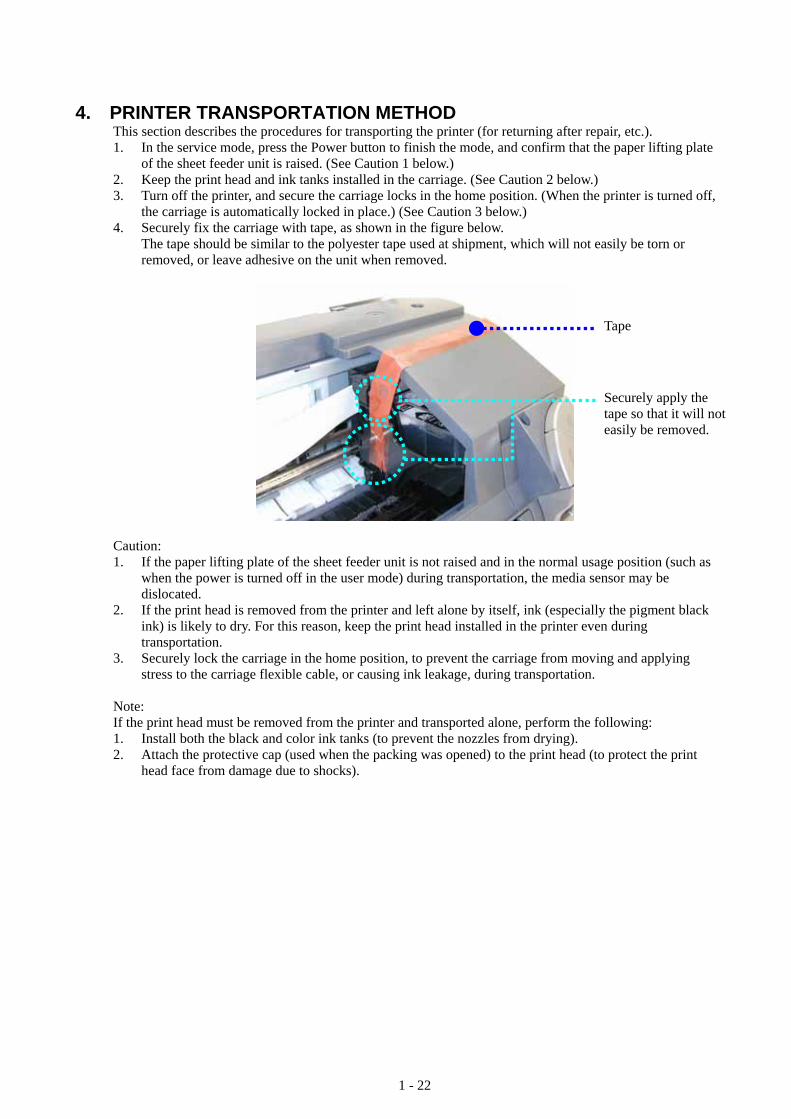
4. PRINTER TRANSPORTATION METHOD This section describes the procedures for transporting the printer (for returning after repair, etc.). 1. In the service mode, press the Power button to finish the mode, and confirm that the paper lifting plate
of the sheet feeder unit is raised. (See Caution 1 below.) 2. Keep the print head and ink tanks installed in the carriage. (See Caution 2 below.) 3. Turn off the printer, and secure the carriage locks in the home position. (When the printer is turned off,
the carriage is automatically locked in place.) (See Caution 3 below.) 4. Securely fix the carriage with tape, as shown in the figure below. The tape should be similar to the polyester tape used at shipment, which will not easily be torn or
removed, or leave adhesive on the unit when removed.
Tape
Securely apply the tape so that it will not easily be removed.
Caution: 1. If the paper lifting plate of the sheet feeder unit is not raised and in the normal usage position (such as
when the power is turned off in the user mode) during transportation, the media sensor may be dislocated.
2. If the print head is removed from the printer and left alone by itself, ink (especially the pigment black ink) is likely to dry. For this reason, keep the print head installed in the printer even during transportation.
3. Securely lock the carriage in the home position, to prevent the carriage from moving and applying stress to the carriage flexible cable, or causing ink leakage, during transportation.
Note: If the print head must be removed from the printer and transported alone, perform the following: 1. Install both the black and color ink tanks (to prevent the nozzles from drying). 2. Attach the protective cap (used when the packing was opened) to the print head (to protect the print
head face from damage due to shocks).
1 - 22

Part 2 TECHNICAL REFERENCE

1. NEW TECHNOLOGIES (1) Direct digital camera printing Printing can be performed directly from a digital camera. In addition to Bubble Jet Direct, the Camera Direct Printing standard, PictBridge, is supported. The print head alignment, which could not be performed during Camera Direct Printing with conventional printer models, can now be performed with the i860 / i865. (By pressing the Resume/Cancel button, and releasing it when the LED blinks 4 times in green, the automatic print head alignment is performed.) (2) Dye-based black ink adopted In addition to the pigment-based black ink, dye-based black ink is adopted, enabling printing using black ink on specialty paper. (In plain paper printing, pigment-based black is used.) (3) Media sense An optical reflective type media sensor is equipped in the sheet feeder unit, and it can classify Canon-recommended paper set in the sheet feeder into 4 groups (transparency, glossy photo paper, plain paper, and coated paper). The media sensor function is disabled in the following conditions: <Conditions in which the media sensor does not operate> i. In the printer driver settings, Media Type and Print Quality settings are other than Plain Paper /
Standard or Plain Paper / High. ii. In Custom Settings of the printer driver’s Maintenance tab, the Identify paper type option is disabled.
(Enabled at default.) <Anticipated troubles and their solutions> If media sensor detection is incorrect, the following troubles are likely to occur: i. In printing on specialty paper, streaks or lines appear, or color hue is improper. (The print quality is
not good.) Solution: Match the Media Type setting in the printer driver with the paper type actually set. ii. In printing on plain paper, printing is smeared, color hue is improper, or black is faint. (The print
quality is not good.) Solution: In Custom Settings of the Maintenance tab, disable Identify paper type. (4) Automatic print head alignment The automatic print head alignment is available via the Resume/Cancel button operation, or via the printer driver utility. Through scanning the print pattern as shown below and detecting its reflection density with the automatic print head alignment sensor (same as the CD-R sensor), the print head is automatically aligned properly. In the automatic print head alignment, the following items are checked, and, if an error is detected, the automatic print head alignment failure error is indicated by the LED blinking in orange 11 times: i. Paper size - Paper width: An error is detected when the paper width is smaller than the specified value. - Paper length: An error is detected when the paper length is shorter than that of A4 / LTR. ii. Faulty printing due to non-ejection of ink - Ink ejection conditions: An error is detected when non-ejection of ink occurs.
2 - 1

<Print pattern for the automatic print head alignment> A4- / Letter-sized plain paper:
Ink ejection conditions check pattern
Paper width check pattern
Paper feed direction
<Anticipated trouble and its solution> i. Even when the paper size is correct (A4 / LTR), and the print pattern is properly printed, the automatic
print head alignment failure error occurs. Solution: In Custom Settings of the printer driver’s Maintenance tab, enable Align heads manually,
and perform the manual print head alignment. (5) CD-R printing (i865 only) By attaching the CD-R tray and tray feeder, printing on a 12 or 8 cm printable CD-R / DVD-R can be performed, through front loading. <Reference> For CD-R printing, the following detection functions are provided: - Presence of the CD-R tray feeder (by the switch sensor inside the platen unit) - CD-R tray position and presence of CD-R (by the CD-R sensor inside the carriage unit) For errors and their solutions relating to CD-R printing, see 2.1. Operator Call Errors. Note: When the CD-R tray feeder is attached, the carriage does not move to the center when the front
cover is opened. Before replacing an ink tank or the print head, remove the CD-R tray feeder. (6) Automatic adjustment of the distance between the paper and the print head According to paper type settings in the printer driver, the distance between the paper and the print head will be automatically adjusted. To change the distance between the paper and the print head, the mechanism to lift the carriage up and down using the ASF motor has been provided. (According to rotation direction of the ASF motor, driving is switched between paper feeding and carriage lifting.) <Anticipated trouble and its solution> i. Paper’s print side is soiled. Solution: In Custom Settings of the printer driver’s Maintenance tab, enable Prevent paper abrasion
(if contact to the print head occurs with paper other than thick paper, such as envelopes and T-shirt transfers).
2 - 2

(7) Photo paper tray When the photo paper tray is attached, 2 types of paper can be set at the same time, photo specialty paper (4” x 6”) in the photo paper tray and other paper in the sheet feeder. Paper types and the maximum number of sheets which can be set in the sheet feeder are limited when the photo paper tray is attached. (5” x 7” or larger sizes of paper are supported by the sheet feeder.) <Paper types and limits in the photo paper tray.
Type Name Size Stacking capacityGlossy Photo Paper GP-401 4 x 6 101.6 x 152.4mm 20 sheets Photo Paper Pro PR-101 4 x 6 101.6 x 152.4mm 20 sheets Photo Paper Plus Glossy PP-101 4 x 6 101.6 x 152.4mm 20 sheets Photo Paper Plus Semi-gloss SG-101 4 x 6 101.6 x 152.4mm 20 sheets
<Paper types and limits in the sheet feeder when the photo paper tray is attached>
Type Name Size Stacking capacityPlain paper 64 to 105g/m2 A4, B5, A5, LTR, LGL 5mm High resolution paper HR-101 A4, LTR 20 sheets Glossy Photo Paper GP-401 A4, LTR 5 sheets Photo Paper Pro PR-101 A4, LTR 5 sheets Photo Paper Plus Glossy PR-101 A4, LTR 5 sheets PR-101 5 x 7 127 x 178mm 5 sheets Matte Photo Paper MP-101 A4, LTR 5 sheets Photo Paper Plus Semi-gloss SG-101 A4, LTR 5 sheets Transparency CF-102 A4, LTR 10 sheets T-shirt transfer TR-301 A4 1 sheet
(8) Auto duplex printing unit (option) When the auto duplex printing unit (an optional unit) is attached to the printer, automated printing on both sides of plain paper (A4, LTR, or B5) is possible. <Anticipated trouble and its solution> i. Paper’s print side is smeared. Solution: In Custom Settings of the printer driver’s Maintenance tab, enable Prevent paper abrasion. Reduce the print density. (9) Paper feed cassette (option) When the paper feed cassette (an optional unit) is attached, a large volume of plain paper (A4, LTR, or B5) can be set.
2 - 3

2. CLEANING MODE AND AMOUNT OF INK PURGED To prevent printing problems due to bubbles, dust, or ink clogging, print head cleaning is performed before the start of printing, except in the following cases: - Cleaning on arrival: Performed when the print head cover is closed. - Cleaning by dot count: Performed after ejection of paper (or after printing on the back side of
paper when auto duplex printing is performed). - Manual cleaning / deep cleaning: Performed manually. <Cleaning mode list> Black: Pigment-based black Color: Dye-based black, cyan, magenta, yellow
Condition Details Amount of ink used (g)
Est. required time (sec.)
On arrival of the printer (both black and color)
First and second cleaning after shipped from the plant.
0.51 (black) 1.67 (color) 80
Dot count cleaning*1
(black/color)
When the specified number of dots are printed from the previous black/color cleaning. (Cyan and magenta dots are counted by large and small nozzles separately.)
Timer cleaning - 0*2
(black only)
If 24 to 60 hours have elapsed since the previous black cleaning till the start of the next printing.
Timer cleaning - 1 (black only)
If 60 to 120 hours have elapsed since the previous black cleaning till the start of the next printing.
Timer cleaning - 2*1
(black/color)
If 120 to 336 hours have elapsed since the previous black/color cleaning till the start of the next printing. (Time is counted by black and color separately.)
0.15 (black) 0.67 (color)
30 (black) 35 (color)
Timer cleaning - 3*1
(both black and color)
If 336 to 1,080 hours have elapsed since the previous black/color cleaning till the start of the next printing.
0.51 (black) 1.16 (color) 65
Timer cleaning - 4 (both black and color)
If 1,080 to 2,160 hours have elapsed since the previous black/color cleaning till the start of the next printing.
0.84 (black) 1.16 (color) 65
Timer cleaning - 5 (both black and color)
If 2,160 to 4,320 hours have elapsed since the previous black/color cleaning till the start of the next printing.
1.64 (black) 1.16 (color) 70
Timer cleaning - 6 (both black and color)
If longer than 4,320 hours have elapsed since the previous black/color printing till the start of the next printing.
1.64 (black) 1.16 (color) 70
If the print head has not been capped before power-on (both black and color)
At ink tank replacement (black/color)
0.31 (black) 1.17 (color)
60 (both black and color) 30 (black) 50 (color)
At print head replacement (both black and color)
When the print head is removed and installed.
0.51 (black) 1.67 (color) 80
Manual cleaning (black/color/both)
- Via the operation panel (both black and color) - Via the printer driver (black, color, or both selectable)
0.15 (black) 0.67 (color)
45 (both black and color) 30 (black) 35 (color)
Deep cleaning (black/color/both)
- Via the printer driver (black, color, or both selectable)
1.64 (black) 1.17 (color)
70 (both black and color) 55 (black) 50 (color)
*1: The period of time from the previous cleaning is counted by black and color separately. For this reason, the cleaning mode may differ according to black or color.
2 - 4

*2: When 24 to 60 hours have elapsed since the previous black cleaning, timer cleaning - 0 is performed. However, this cleaning will be conducted up to 5 times from the printer installation, and no further timer cleaning - 0 will be performed.
2 - 5

3. FAQ (Specific Problems and Solutions) No. Occurrence
level* Function Symptom Condition Cause Solution Possible call or complaint
1. B Paperfeeding
No paper feeding - Plain paper (A4-/LTR-/LGL-sized heavy paper, such as Brilliant White Paper)
- When many sheets are set.
- Reduce the number of sheets to set in the sheet feeder, to below half the reference mark.
- Paper does not feed. - No paper error (operator call error)
- The printer does not respond.
2. B Printresults
Contact of the paper’s trailing edge to the print head
- Plain paper - Paper conditions (curled)
If paper is curled (with the edges upward), the trailing edge will contact the print head.
- Straighten the paper. - Increase the space between
the paper and the print head (to prevent the paper edge from contacting the print head).
- Printout is smeared. - Lines or streaks appear on printouts.
3 B Printresults
Contact of the paper to the print head (when using the auto duplex printing unit)
- Plain paper - Duplex printing (using the
auto duplex printing unit) - Printing of a heavy-duty
pattern
Immediately after printing, paper ripples form, contacting the print head.
- Increase the space between the paper and the print head (to prevent the paper from contacting the print head.)
- Reduce the print density.
- Printout is smeared. - Lines or streaks appear on printouts.
* Occurrence level: A: The symptom is likely to occur frequently. (Caution required) B: The symptom may occur under certain conditions, but likeliness is assumed very low in practical usage. C: The symptom is unlikely to be recognized by the user, and no practical issues are assumed.
2 - 6


![Mabch h, I860.] THE CARNIVAL AT ROME. 281](https://static.fdocuments.net/doc/165x107/61f314e2c7f5bf529b5a20c6/mabch-h-i860-the-carnival-at-rome-281.jpg)


