CAMERA CONTROL NETWORK ADAPTOR CNA-1 - …pdf.crse.com/manuals/4431827011.pdfOverview 3 Overview...
29
CAMERA CONTROL NETWORK ADAPTOR CNA-1 TECHNICAL MANUAL [English] 1st Edition
Transcript of CAMERA CONTROL NETWORK ADAPTOR CNA-1 - …pdf.crse.com/manuals/4431827011.pdfOverview 3 Overview...

CAMERA CONTROL NETWORK ADAPTOR
CNA-1
TECHNICAL MANUAL [English]
1st Edition
2
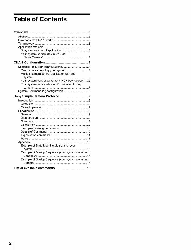
Table of Contents
Overview..................................................................... 3Abstract ............................................................................3How does the CNA-1 work? ............................................3Terminology .....................................................................3Application example .........................................................3
Sony camera control application ..................................3Your system participates in CNS as
“Sony Camera” .........................................................3
CNA-1 Configuration ................................................. 4Examples of system configurations..................................4
One camera control by your system ............................4Multiple camera control application with your
system ......................................................................5Your system controlled by Sony RCP peer-to-peer .....6Your system participates in CNS as one of Sony
camera .....................................................................7System/Command log configuration ................................8
Sony Simple Camera Protocol ................................. 9Introduction ......................................................................9
Overview ......................................................................9Overall operation .........................................................9
Specification.....................................................................9Network ........................................................................9Data structure ..............................................................9Command ....................................................................9Connection ...................................................................9Examples of using commands ...................................10Details of Command ..................................................10Types of the command ..............................................11Rules ..........................................................................12
Appendix ........................................................................13Example of State Machine diagram for your
system ....................................................................13Example of Startup Sequence (your system works as
Controller) ...............................................................14Example of Startup Sequence (your system works as
Camera) .................................................................15
List of available commands.................................... 16

Overview
Abstract
CNA-1 is a network point that works as a “Protocol converter”. It acts as an entrance to the Sony Camera Network System (CNS).Your system can control a Sony Camera, and can be controlled from Sony Control Panels via CNA-1 with its communication protocol.
How does the CNA-1 work?
CNA-1 participates in CNS as another “Sony protocol capable” device.It can talk to your system with a simple command protocol (Sony Simple Camera Protocol: SSCP), providing a simple communication mechanism for your system.It mutually translates the protocol for a Sony Camera to SSCP.
Terminology
CNS: Sony Camera Network SystemA network system consisting of Sony Cameras (Sony CCUs) and Sony Control Panels, connected to each other via TCP/IP.
SPP: Sony Proprietary ProtocolA communication protocol used by CNS devices.
SSCP: Sony Simple Camera ProtocolA communication protocol between CNA-1 and your system.
RCP-mode, CAM-mode:An emulation mode of CNA-1.CNA-1 acts as a Sony Control Panel in RCP-mode.CNA-1 acts as a Sony Camera in CAM-mode.This configuration can be selected using the Web configurator of CNA-1.
Application example
Sony camera control applicationIn this application, your system behaves as a controller for a Sony Camera.Your system can control a Sony Camera via CNA-1 (RCP-mode configured) with SSCP.
Your system participates in CNS as “Sony Camera”In this application, your system may behave as a Camera or other device similar to a camera.Your system can be controlled from Sony Control Panels viaCNA-1 (CAM-mode configured) with SSCP.
Your system(Behaves as Control Panel)
Sony Camera
CNA-1TranslatesSSCP y SPPControl command
(SSCP)Sony Proprietary Protocol (SPP)
Your system(Behaves as Camera)
Sony Control Panel
CNA-1TranslatesSSCP y SPPControl command
(SSCP)Sony Proprietary Protocol (SPP)
3Overview

4
CNA-1 Configuration
Examples of system configurations
One camera control by your system
CNA-1 setup For details of the following setting items, see “Operation Manual (page 17).”
CNS Configuration CNS Mode Bridge
Master Mode Disable
Master IP Address Variable
Target IP Address CCU’s IP Address
Device No. Variable
Gateway Configuration Gateway Mode Enable
Emulation Mode RCP
CNA-1
Your system work as controller
Network hubCCUBridge mode
Camera head
CNA-1 Configuration

Multiple camera control application with your system
CNA-1 setup For details of the following setting items, see “Operation Manual (page 17).”
Device No. Configuration for CNA-1In this case, Device number of CNA-1 must be set to different number from RCPs connected to the network. CNA-1 will be recognized as one of RCP and CNA-1’s Device number is handled as RCP number in CNS.In default setting of RCP assignment, RCP can control CCU (and camera) which has same number from RCP number.
Ex. RCP No. (1) can control CCU No. (1)CNA-1 (1)-(3) has Device number (4)-(6). In this setting, CNA-1 cannot control any CCU (and camera) (4)-(6) because CCU (4)-(6) is not connected in this network.For control (1)-(3) camera by CNA-1 (1)-(3), CNA-1 must be assigned to CCU (and camera) (1)-(3) by RCP assignment function provided from MSU. MSU will find CNA-1 as RCP (4)-(6).For detail of RCP assignment function, see MSU's Operation Manual.
CNS Configuration CNS Mode MCS
Master Mode Disable
Master IP Address Master MSU’s IP address
Target IP Address Variable
Device No. Depends on RCPs connected to the network.
Gateway Configuration Gateway Mode Enable
Emulation Mode RCP
CNA-1 (1)Device No. (4)
Your system work as controller (1)
Network hub
CCU (1)MCS mode: ClientCCU No. (1)Camera head
CCU (2)MCS mode: ClientCCU No. (2)Camera head
CCU (3)MCS mode: ClientCCU No. (3)Camera head
RCP (1)MCS mode: ClientRCP No. (1)
MSUMCS mode: Master
RCP (2)MCS mode: ClientRCP No. (2)
RCP (3)MCS mode: ClientRCP No. (3)
CNA-1 (2)Device No. (5)
CNA-1 (3)Device No. (6)
Your system work as controller (2)
Your system work as controller (3)
5CNA-1 Configuration

6
Your system controlled by Sony RCP peer-to-peer
CNA-1 setup For details of the following setting items, see “Operation Manual (page 17).
”
RCP setupFor details of the following setting items, see RCP’s Operation Manual.
”
CNS Configuration CNS Mode Bridge
Master Mode Disable
Master IP Address Variable
Target IP Address Variable
Device No. Variable
Gateway Configuration Gateway Mode Enable
Emulation Mode CAM
CNS Configuration CNS Mode Bridge
Bridge Mode: Connection mode Semi-Auto
Bridge Mode: Target CNA-1’s IP address
CNA-1
Your system work as camera
Network hub
RCPBridge mode
CNA-1 Configuration

Your system participates in CNS as one of Sony camera
CNA-1 setup For details of the following setting items, see “Operation Manual (page 17).
”
Device No. Configuration for CNA-1In this case, Device number of CNA-1 must be set to different number from CCUs connected to the network. CNA-1 will be recognized as one of camera and CNA-1's Device number is handled as CCU number in CNS.CNA-1’s Device number is set to (3). Therefore, MSU can find CNA-1 as Camera (3) and also RCP (3) can control CNA-1 as Camera (3).
CNS Configuration CNS Mode MCS
Master Mode Disable
Master IP Address Master MSU’s IP address
Target IP Address Variable
Device No. Depends on CCUs connected to the network.
Gateway Configuration Gateway Mode Enable
Emulation Mode CAM
CNA-1Device No. (3)
Your system work as camera
Network hub
CCU (1)MCS mode: ClientCCU No. (1)Camera head
CCU (2)MCS mode: ClientCCU No. (2)Camera head
RCP (1)MCS mode: ClientRCP No. (1)
MSUMCS mode: Master
RCP (2)MCS mode: ClientRCP No. (2)
RCP (3)MCS mode: ClientRCP No. (3)
7CNA-1 Configuration
8
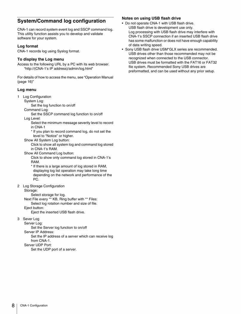
System/Command log configuration
CNA-1 can record system event log and SSCP command log. This utility function assists you to develop and validate software for your system.
Log formatCNA-1 records log using Syslog format.
To display the Log menuAccess to the following URL by a PC with its web browser.
“http://(CNA-1's IP address)/admin/log.html”
For details of how to access the menu, see “Operation Manual (page 16)”
Log menu
1 Log ConfigurationSystem Log:
Set the log function to on/offCommand Log:
Set the SSCP command log function to on/offLog Level:
Select the minimum message severity level to record in CNA-1* If you plan to record command log, do not set the
level to “Notice” or higher.Show All System Log button:
Click to show all system log and command log stored in CNA-1's RAM.
Show All Command Log button:Click to show only command log stored in CNA-1’s RAM.* If there is a large amount of log stored in RAM,
displaying log list operation may take long time depending on the network and performance of the PC.
2 Log Storage ConfigurationStorage:
Select storage for log.Next File every ** KB, Ring buffer with ** Files:
Select log rotation number and size of file.Eject button:
Eject the inserted USB flash drive.
3 Sever LogServer Log:
Set the Server log function to on/offServer IP Address:
Set the IP address of a server which can receive log from CNA-1.
Server UDP Port:Set the UDP port of a server.
Notes on using USB flash drive• Do not operate CNA-1 with USB flash drive.
USB flash drive is development use only.Log processing with USB flash drive may interfere with CNA-1's SSCP connection if an inserted USB flash drive has some malfunction or does not have enough capability of data writing speed.
• Sony USB flash drive USM*GLX series are recommended.USB drives other than those recommended may not be recognized when connected to the USB connector.USB drives must be formatted with the FAT16 or FAT32 file system. Recommended Sony USB drives are preformatted, and can be used without any prior setup.
CNA-1 Configuration

Sony Simple Camera Protocol
Introduction
OverviewSony Simple Camera Protocol (SSCP) is a communication protocol between your system and CNA-1. It is an ASCII character based protocol via TCP/IP. The port number of TCP is configurable.It has no complex mechanism such as Application-level session control, Keep-alive, Device identification or Authentication. Therefore, your system can control Sony Cameras, or can be controlled from Sony Control Panels, using just send/receive command(s) without any complex procedure.
Overall operationBasically, CNA-1 listens to a specified TCP port and awaits a connection from your system. When a connection is established, CNA-1 is ready to send and receive control commands immediately.The connection behavior varies based on its emulation mode. (See connection section.)
Specification
NetworkLink layer:
Ethernet, 100BASE-TXNetwork layer:
IPv4Transport Layer:
TCPPort number is configurable other than 7700 (CNA-1 reserved) or well known ports (1-1023)
Data structurePacket:
Variable length depends on MTU configuration.MTU value of CNA-1 is 1500 bytes. It is preferred that MTU of your system is configured less than 1500.
Data:ASCII character codes:• Available ASCII printable characters:
– Lower alpha: “a” .. “z”– Higher alpha: “A” .. “Z”– Digit: “0” .. “9”– Others: “,” (comma)
• Available ASCII control characters:– New line: “\n”, “\r”
Note
If a packet includes unavailable characters or bytes, it is handled as an invalid packet and discarded.
CommandA command is described by Hexadecimal data assembled by ASCII characters above.
Lower and upper case alphabetical/numeric:2 characters requires 1 byte
Comma:Delimiter of each byte
New line:Termination of a command, “\n”, “\r” and “\n\r” are available.
Example: (Set Master Black to 0):“23,a9,00,00\n”
Constructing a command by multi-packet is possible.Example:
“23,” Packet1“a9” Packet2“,00,00” Packet3“\n” Packet4CNA-1 will concatenate packets (1-4) and recognize that as “23,a9,00,00\n”.
Multiple commands in a packet is possible.Example (Set White Balance R-ch, G-ch, B-ch to 0 at the same time):
“23,01,00,00\n23,02,00,00\n23,03,00,00\n”
Important limitationMaximum command length: 160 byte (characters) / packet
If CNA-1 cannot find the terminator (New line) after it receives 160 bytes, it will discard the received data.
Minimum inter-packet (including complete command(s)) interval: 50 msec
This limitation is important to avoid Camera malfunctions. An overly short inter-packet gap can impose a heavy load on a Camera’s processor, and interfere with its processing. It is possible that unexpected Camera errors might occur.If your system needs to send a number of commands, the commands must be concatenated and put in a packet.In an application including periodic scan for Camera status, it is recommended that the inter-packet-interval is set to as long as possible, for effective Camera operation.
Terminator:CNA-1 only sends “\n” as terminator even if it receives “\r” and “\n\r”.
Connection
CNA-1 configured for RCP mode
1 CNA-1 searches for a Sony Camera or Sony CCU by CNS configuration.
2 When CNA-1 connects to that, CNA-1 listens to specified TCP port and awaits a connection from your system.
3 Your system ready to connect to CNA-1
Note
If CNA-1 loses its CNS connection (to Camera or CCU), it terminates the connection with your system, and returns to (1).
9Sony Simple Camera Protocol

10
CNA-1 configured for CAM mode
1 After booting CNA-1, it listens to the specified TCP port, and awaits connection from your system immediately.
2 Your system connects to CNA-1.
3 When connection is established, CNA-1 searches a CNS by its configuration and participate in CNS as one of a Sony Camera.
Note
If CNA-1 loses connection with your system, it closes the session to CNS, and returns to (1).
Examples of using commandsFor details of commands, see “Details of Command” and “List of available commands”.
Master Gain control (Inc/Dec command)Get current Gain value
Send: “20,01,00\n” => Receive: “21,01,02\n” (Reply current status from Camera)
Increase GainSend: “21,01,80\n” => Receive: “21,01,03\n” (in case of current parameter being 02)
Reduce GainSend: “21,01,40\n” => Receive: “21,01,01\n” (in case of current parameter being 02)
Set Gain value directorySend: “21,01,01\n” => Receive: “21,01,01\n”
Control several Camera functions (Bit command)Get current function states (ON or OFF) at CHU_FUNCTION01
Send: “20,81,00\n” => Receive: “21,81,31\n” “31” is handled as bits-array: “00110001” means:• Knee Saturation (Bit7) = OFF• Auto Knee (Bit6) = OFF• Knee (Bit5) = ON• Gamma (Bit4) = ON• Flare (Bit3) = OFF• S-EVS (Bit2) = OFF• ECS (Bit1) = OFF• Shutter (Bit0) = ON
Invert function statesSend: “20,81,33\n” (00110011) => Receive: “21,81,02\n” (in above condition)• Knee Saturation (Bit7) = OFF (0 no operation)• Auto Knee (Bit6) = OFF (0 no operation)• Knee (Bit5) = OFF (1 ON to OFF)• Gamma (Bit4) = OFF (1 ON to OFF)• Flare (Bit3) = OFF (0 no operation)• S-EVS (Bit2) = OFF (0 no operation)• ECS (Bit1) = ON (1 OFF to ON)• Shutter (Bit0) = OFF (1 ON to OFF)
Set function statesSend: “21,81,31\n” (00110001) => Receive: “21,81,31\n” (in above condition)• Knee Saturation (Bit7) = OFF • Auto Knee (Bit6) = OFF
• Knee (Bit5) = ON • Gamma (Bit4) = ON • Flare (Bit3) = OFF • S-EVS (Bit2) = OFF • ECS (Bit1) = OFF • Shutter (Bit0) = ON
Set function status with bit-maskSend: “29,81,03,11\n” (00000011 & 00010001) => Receive: “21,81,21\n” (in above condition)• Knee Saturation (Bit7) = OFF (0-0 no operation)• Auto Knee (Bit6) = OFF (0-0 no operation)• Knee (Bit5) = ON (0-0 no operation)• Gamma (Bit4) = OFF (0-1 Effective OFF)• Flare (Bit3) = OFF (0-0 no operation)• S-EVS (Bit2) = OFF (0-0 no operation)• ECS (Bit1) = OFF (1-0 no operation)• Shutter (Bit0) = ON (1-1 Effective ON)
Control White Balance R-Channel of Camera (Word command)Get current value
Send: “22,01,00,00\n” => Receive:“23,01,01,40\n”Current value is “01,40” = 0x0140 (16bits Hex)
Add/Subtraction controlSend: “22,01,00,01\n” => Receive: “23,01,01,41\n” (Add +0001)Send: “22,01,ff,ff\n” => Receive: “23,01,01,3f\n” (Subtraction -0001)
Set value directorySend: “23,01,00,01\n” => Receive: “23,01,00,01\n”
Details of CommandCommand has 2 parts, “Command group: CMD-GP” and “Parameter: PARAM”.CMD-GP is a byte at the head of a command. PARAM is one or a number of bytes describing the contents of a command. The length of PARAM is dependent on CMD-GP.
“[CMD-GP],[PARAM0],[PARAM1],[PARAM2],...,[PARAM N]\n”
Example: “23,a9,00,00\n”CMD-GP: “23”
Adjust the word-size parameter of CameraPARAM: “a9,00,00”
PARAM0:“a9” Parameter address of Master Black of Camera
PARAM1-2:“00,00” 2 bytes parameter value of Master Black (PARAM0)
Sony Simple Camera Protocol

Types of the commandThere are several types of commands and formats, depending on CMD-GP or combination of CMD-GP and PARAM0.
[CMD-GP]: Categorizes a command into “Byte type”, “Word type”, “Other type”, and appends a control method “Relative” or “Absolute”
[CMD-GP] + [PARAM0]:Categorizes “Byte type command” into “Byte command”, “Bit command”, “Inc/Dec command”
Almost all commands have two different control types: “Relative” and “Absolute” assigned to a different CMD-GP (see the List of available commands)
Example: Master Black control• Relative control: “22,a9,00,01\n” This command “adds”
0x0001 to the current parameter• Absolute control: “23,a9,00,01\n” This command “sets”
0x0001 to the parameter (overwrite)
Byte commandControls or Queries a byte-size parameter of a Camera.
Format:• “[CMD-GP],[PARAM0],[PARAM1]\n”• PARAM0: Parameter address• PARAM1: Value
Relative control:It means a status query. PARAM1 is ignored and does not affect the status of the Camera.
Absolute control:Set the parameter of Camera specified by the PARAM0 address to PARAM1, or a response of the value of the parameter from the Camera.
Bit commandControls or Queries the ON or OFF state of a function of a Camera using bit (0 or 1).
Format:• “[CMD-GP],[PARAM0],[PARAM1]\n”• PARAM0: Parameter address• PARAM1: Value affects each bit
Relative control:Inverts the function state specified by the PARAM0 address ON to OFF, or OFF to ON when bit is set to 1.If PARAM1 bits are all set to 0, it means a status query.
Absolute control:Set the state at the PARAM0 address to PARAM1 or a response of the value of the parameter from the Camera.
Inc/Dec commandIncrements or decrements a Camera parameter and also adjusts a value directory.
Format:• “[CMD-GP],[PARAM0],[PARAM1]\n”• PARAM0: Parameter address• PARAM1: ValuePARAM1
bit7-6: Inc/Dec control[00] Set a value directory or status query[01] Increment the parameter specified by the PARAM0 address[10] Decrement the parameter specified by the PARAM0 address[11] N/A
bit5-0: Value of the parameter
Relative control:bit5-0 is ignored.bit7-6 [00] or [10] or [01]: Parameter (bit5-0) query.bit7-6 [11]: Maximum value query for the parameter (bit5-0).
Absolute control:bit7-6:
[00]: Set the parameter specified by the PARAM0 address to bit5-0.[01]: Increment the parameter. bit5-0 is ignored.[10]: Decrement the parameter. bit5-0 is ignored. [11]: Maximum value reply from a Camera. Do not use this bit pattern to control.
bit5-0: Value of the parameter.
Word commandAdjust a word-size parameter of a Camera, or status response of it.
Format:“[CMD-GP],[PARAM0],[PARAM1],[PARAM2]\n”PARAM0: Parameter addressPARAM1-2: Value 16bit
PARAM1: Higher bytePARAM2: Lower byte
Relative control:PARAM1-2 [0x0000]:Parameter query.
[Others]: Add PARAM1-2 to the current parameter.
Absolute control:Set the parameter to PARAM1-2.
Other commandDepends on CMD-GP, details are described in the list of commands.
11Sony Simple Camera Protocol

12
Rules
Request and ResponseRequests and response correspond loosely.There is no one to one mapping between requests and responses: “No reply” means “I can’t process such a command”.Do not send anything if an error has occurred. Errors must be handled the same as “No command”.
Responses from a Camera can be sent to your system anytime without a request from your system. The status of Camera can be changed by itself (Auto iris function, etc.), changed by a camera operator’s hand manually or changed by another control panel connected to the Camera. The Camera sends status changes to all connected controllers.Your system can ignore any responses not needed by your system.
When to sendIn the case of your system working as a controller for a Camera, your system should send a parameter query that it want to get.Almost Sony Camera only send status when its status is changed by receiving commands or its function (ex. automatic iris control or etc.).The status of your system can be updated by receiving status responses from a connected Sony Camera by sending status queries to that Camera (via CNA-1).
In another case, your system works as a Camera among CNS, your system should send commands when its status is changed (must behave like a Sony Camera). The commands must be absolute commands in this case.If Sony control panels receive no absolute command responses from your system, they cannot update their status and also cannot update the displays.Therefore, the absolute command responses from your system are necessarily for the control system.
Permission control (Panel Active control)CNS supports operating multiple cameras by multiple control panels. In case of using the Panel Assign Function, control panels are assigned to Cameras by a CNS Master device, such as MSU.The assignment function allows duplicate assignment, meaning one camera can be controlled by two or more control panels. Control conflicts can occur in this case. Therefore, permission control for the Camera is determined by the CNS Master device, using Panel Active command.If a network system with your system requires permission control, your system should use Panel Active command and your system’s Panel Active state should be controlled by the CNS Master device because CNA-1 behaves in the same way as the Sony Control Panel in RCP-mode.In a single connection (CNA-1 configured Bridge mode of CNS setting), the permission control is managed by CNA-1 itself.
Permission allows your system to send all available commands. Without permission, your system can send only Status Query commands (Control commands are rejected). Permission control does not regulate receiving commands.
When your system receives permission using Panel Active command, another control panel assigned to the same Camera loses permission.If your system does not want to affect the permission of another control panel, your system can use Para command instead of Panel Active command. Usage of Para command is the same as Panel Active command. However, permission by Para command does not allow controlling of Iris, Master Black and sending Absolute Word command.
A configuration of CNA-1 “Panel Active Function Enable/Disable” enables this permission control function. If Panel Active Function is enabled, CNA-1 manages Panel Active state and your system can use Panel Active/ Iris Active/ Para commands. If the function is disabled, CNA-1 rejects these commands.
Permission control is not necessarily in the network system. Your system can ignore that and can send command if CNA-1 configured “Panel Active Disable (default)”. However, if a duplicate assignment is set to CNA-1 and another control panel, conflict can occur between other control panels in the no permission control state. Especially, Absolute type commands will certainly conflict, and erratic Camera behavior can occur. For this reason, pay close attention to Absolute type commands
Panel active command examples:Get current permission state
Send: “0b,90,01,00\n” => Receive: “0b,XX,01,81\n” XX is ID of Master device. Value “81” means sender (your system) has No permission
Send: “0b,90,01,00\n” => Receive: “0b,XX,01,82\n” XX is ID of Master device. Value “82” means sender (your system) has permission to control
Require the permissionSend: “0b,90,01,02\n” => Receive: “0b,XX,01,81\n” or “0b,XX,01,82\n”
Release the permissionSend: “0b,90,01,01\n” => Receive: “0b,XX,01,81” or “0b,XX,01,82\n”
Sony Simple Camera Protocol

Appendix
Example of State Machine diagram for your system
Command Process Watch Status Process
Waiting a command from CNA-1
Your system startup
Command validation
Command filteringNOP, put off the command
Change your systemstatus
Command recieved
EstablishedNot established
Find a statuschangeNo status
changed
Connection refused
Connection refused
Status changecomplete
Valid command
Operative command
Sendcomplete
Status must be sent to Camera/Panel
Send failed (Connection refused)
Your systempower off
Status must not be sent to Camera/Panel
Unknowncommand
Invalidcommand
Return to start
Start
Checking your systemstatus
Analyze changedstatus
Send command toCNA-1
Return to start
Return to start
Connecting to CNA-1 (TCP)
13Sony Simple Camera Protocol

14
Example of Startup Sequence (your system works as Controller)
CNA-1 Sony CameraYour system (works as Control panel)
1: Startup ( ) 3: Startup ( )
14: change camera status ( )
2: Startup ( )
4: [socket] listen (port: 7700)
This port number can be set to any port other than 7700 or 1-1023.
Send status querycommand(s) your system want to receive
17: refresh ( )
5: [socket] connect (port: 7700)
6: [socket] accept ( )
7: [SPP] start_session ( )
15: [SPP] reply_status ( )
8: [SPP] session_accept ( )
9: [socket] listen (port: XXXX)
10: [socket] connect (port: XXXX)
11: [socket] accept ( )
12: [SSCP] scan_camera_status ( )
13: [SPP] scan_camera_status ( )
16: [SSCP] reply_status ( )
Sony Simple Camera Protocol
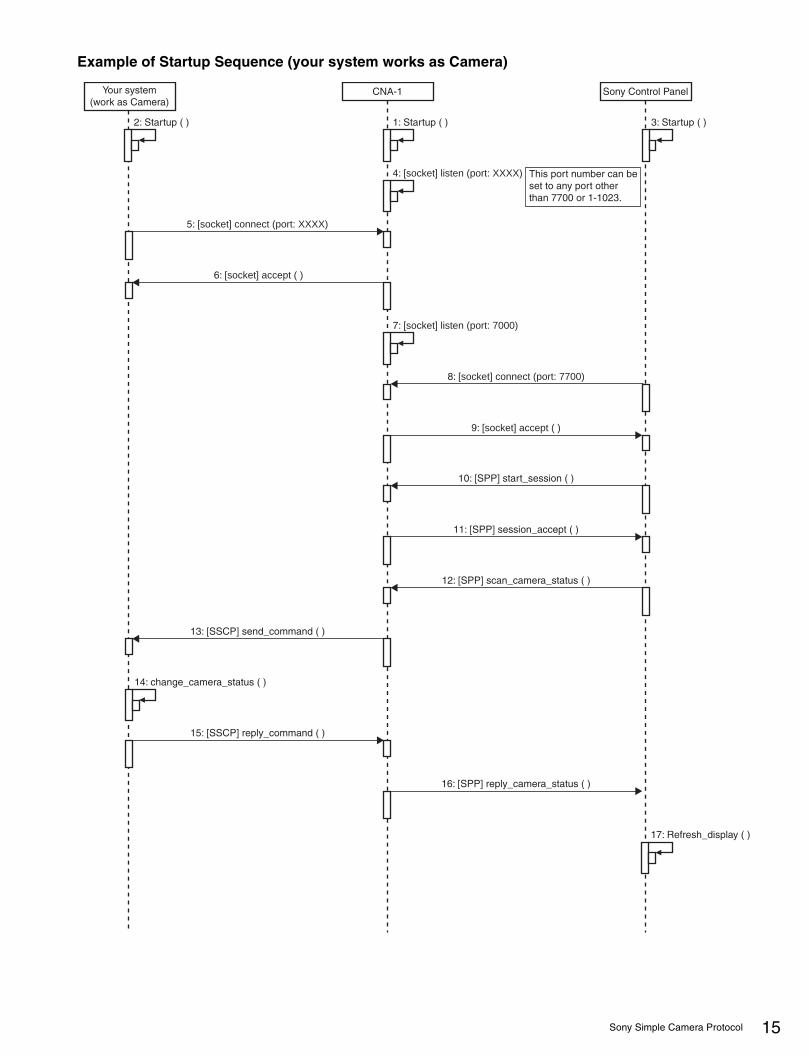
Example of Startup Sequence (your system works as Camera)
CNA-1 Sony Control PanelYour system(work as Camera)
1: Startup ( ) 3: Startup ( )2: Startup ( )
4: [socket] listen (port: XXXX)
7: [socket] listen (port: 7000)
14: change_camera_status ( )
5: [socket] connect (port: XXXX)
13: [SSCP] send_command ( )
16: [SPP] reply_camera_status ( )
17: Refresh_display ( )
15: [SSCP] reply_command ( )
6: [socket] accept ( )
8: [socket] connect (port: 7700)
9: [socket] accept ( )
10: [SPP] start_session ( )
11: [SPP] session_accept ( )
12: [SPP] scan_camera_status ( )
This port number can be set to any port other than 7700 or 1-1023.
15Sony Simple Camera Protocol

16
List of available commands
Command
UsageCommand Category
Command Type
Command Name
CMD_GP(Relative/Absolute)
PARAM0 PARAM1 PARAM2
System Control
Bit command
tally 0x08 0x20TALLY_DATA
–
* Receive onlyWhen Sony CCU inputs a Tally signal via External I/O, The CCU sends the tally command to CNA-1TALLY_DATA=
bit0 Redbit1 Greenbit2 Yellow
Other command
call 0x0bSENDER_
SRCID0x00
CALL VALUE
SENDER_SRCID=0x90 when your system works as Controller0x20 when your system works as Camera
CALL VALUE=0x80 current status query0x81 Call off0x82 Call on (two seconds)
panel_active 0x0bSENDER_
SRCID0x01
CONTROL VALUE
SENDER_SRCID=0x90
CONTROL VALUE=0x00 Current active status query0x01 Active-off (release own control to Camera)0x02 Active-on (get control to Camera)0x81 Active-off status reply0x82 Active-on status reply
*This command is available in condition of Panel Active Function of CNA-1 is enabled (default is disable).
iris_active 0x0bSENDER_
SRCID0x02
CONTROL VALUE
Same as panel_active command but this command affects only Iris and MasterBlack control.
para 0x0bSENDER_
SRCID0x03
CONTROL VALUE
Same as panel_active command but this command does not affect permission of another control panel (parallel control can be used).* Iris, Master Black, all absolute word commands are not allowed in the permission received by this command.
List of available commands

CHUFunctionControl
Inc/Dec command
shutter_speed
0x20/0x21
0x00INC/DEC
value–
Bit5-000: 1/6001: 1/10002: 1/12503: 1/25004: 1/50005: 1/100006: 1/200007: 1/300008: 1/400009: 1/50000A: 1/100000B: 1/320C: 1/330D: 1/400E: 1/480F: 1/5010: 1/9611: 1/120
master_gain 0x01INC/DEC
value–
Bit5-000: -6dB01: -3dB02: 0dB03: 3dB04: 6dB05: 9dB06: 12dB07: 15dB08: 18dB09: 21dB0A: 24dB0B: 27dB0C: 30dB0D: 33dB0E: 36dB0F: 39dB10: 42dB11: 45dB12: 48dB13: 51dB14: 54dB15: 57dB16: 60dB
nd_filter 0x03INC/DEC
value–
Bit5-000: Filter 1-1 (ND 1)01: Filter 1-2 (ND 2)02: Filter 1-3 (ND 3)03: Filter 1-4 (ND 4)04: Filter 1-5 (ND 5)
cc_filter 0x04INC/DEC
value–
Bit5-000: Filter 2-1 (CC A)01: Filter 2-2 (CC B)02: Filter 2-3 (CC C)03: Filter 2-4 (CC D)04: Filter 2-5 (CC E)
Command
UsageCommand Category
Command Type
Command Name
CMD_GP(Relative/Absolute)
PARAM0 PARAM1 PARAM2
17List of available commands

18
CHUFunctionControl
Inc/Dec command
master_gamma_
select
0x20/0x21
0x06INC/DEC
value–
Bit5-000: 101: 0.9502: 0.9003: 0.8504: 0.8005: 0.7506: 0.7007: 0.6508: 0.6009: 0.550A: 0.500B: 0.450C: 0.400D: 0.350E: 0.300F: 0.2510: 0.2011: 0.1512: 0.10
auto_iris_window_
select0x0a
INC/DEC value
–
Bit5-000: Cutting the top end01: Cutting the top, bottom, left and right ends02: Cutting the left and right ends03: Cutting uniformly04: Cutting the top, left and right ends05: Cutting the bottom end06: Variable-Window
preset_mtx_select
0x0dINC/DEC
value–
Bit5-000: Default01: SMPTE-240M02: REC-70903: SMPTE-WIDE04: NTSC05: EBU
standard_gamma_
table_mode0x13
INC/DEC value
–
Bit5-000: Standard01: Special 102: Special 203: User
standard_gamma_
select0x14
INC/DEC value
–
special_gamma_
select0x15
INC/DEC value
–
hyper_gamma_
select0x16
INC/DEC value
–
user_gamma_select
0x17INC/DEC
value–
blk_gamma_RGB_low_
range0x18
INC/DEC value
–
Bit5-000: Low Range01: Lower Middle Range02: Higher Middle Range03: High Range
Command
UsageCommand Category
Command Type
Command Name
CMD_GP(Relative/Absolute)
PARAM0 PARAM1 PARAM2
List of available commands

CHUFunctionControl
Inc/Dec command
low_key_sat_low_range
0x20/0x21
0x1dINC/DEC
value–
Bit5-000: Low Range01: Lower Middle Range02: Higher Middle Range03: High Range
sls_select 0x20INC/DEC
value–
Bit5-000: 1F01: 2F02: 3F03: 4F04: 5F05: 6F06: 7F07: 8F08: 11F09: 12F0A: 15F0B: 16F0C: 22F0D: 24F0E: 25F0F: 30F10: 32F11: 45F12: 48F13: 50F14: 60F15: 64F16: 90F17: 96F18: 100F19: 120F1A: 128F1B: 180F1C: 192F1D: 200F1E: 240F1F: 256F
digital_extender
0x27INC/DEC
value–
Bit5-000: x1.0 (OFF)01: x1.502: x2.003: x2.504: x3.005: x3.506: x4.007: x4.508: x5.009: x5.50A: x6.00B: x6.50C: x7.00D: x7.50E: x8.0
flicker_reduce_area
_select0x28
INC/DEC value
–* Only for HDC3300.
compensation 0x29INC/DEC
value–
Command
UsageCommand Category
Command Type
Command Name
CMD_GP(Relative/Absolute)
PARAM0 PARAM1 PARAM2
19List of available commands
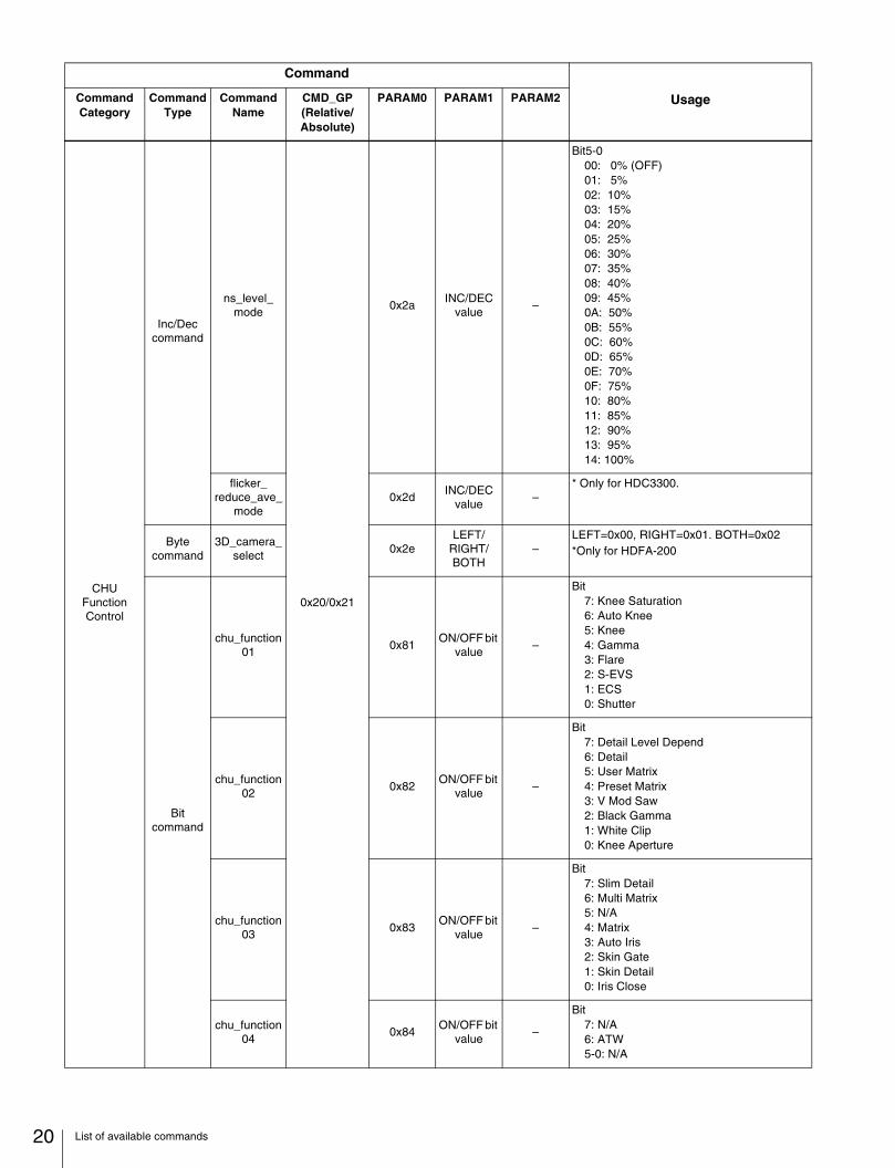
20
CHUFunctionControl
Inc/Dec command
ns_level_mode
0x20/0x21
0x2aINC/DEC
value–
Bit5-000: 0% (OFF)01: 5%02: 10%03: 15%04: 20%05: 25%06: 30%07: 35%08: 40%09: 45%0A: 50%0B: 55%0C: 60%0D: 65%0E: 70%0F: 75%10: 80%11: 85%12: 90%13: 95%14: 100%
flicker_reduce_ave_
mode0x2d
INC/DEC value
–* Only for HDC3300.
Byte command
3D_camera_select
0x2eLEFT/
RIGHT/BOTH
–LEFT=0x00, RIGHT=0x01. BOTH=0x02*Only for HDFA-200
Bit command
chu_function01
0x81ON/OFF bit
value–
Bit7: Knee Saturation6: Auto Knee5: Knee4: Gamma3: Flare2: S-EVS1: ECS0: Shutter
chu_function02
0x82ON/OFF bit
value–
Bit7: Detail Level Depend6: Detail5: User Matrix4: Preset Matrix3: V Mod Saw2: Black Gamma1: White Clip0: Knee Aperture
chu_function03
0x83ON/OFF bit
value–
Bit7: Slim Detail6: Multi Matrix5: N/A4: Matrix3: Auto Iris2: Skin Gate1: Skin Detail0: Iris Close
chu_function04
0x84ON/OFF bit
value–
Bit7: N/A6: ATW5-0: N/A
Command
UsageCommand Category
Command Type
Command Name
CMD_GP(Relative/Absolute)
PARAM0 PARAM1 PARAM2
List of available commands
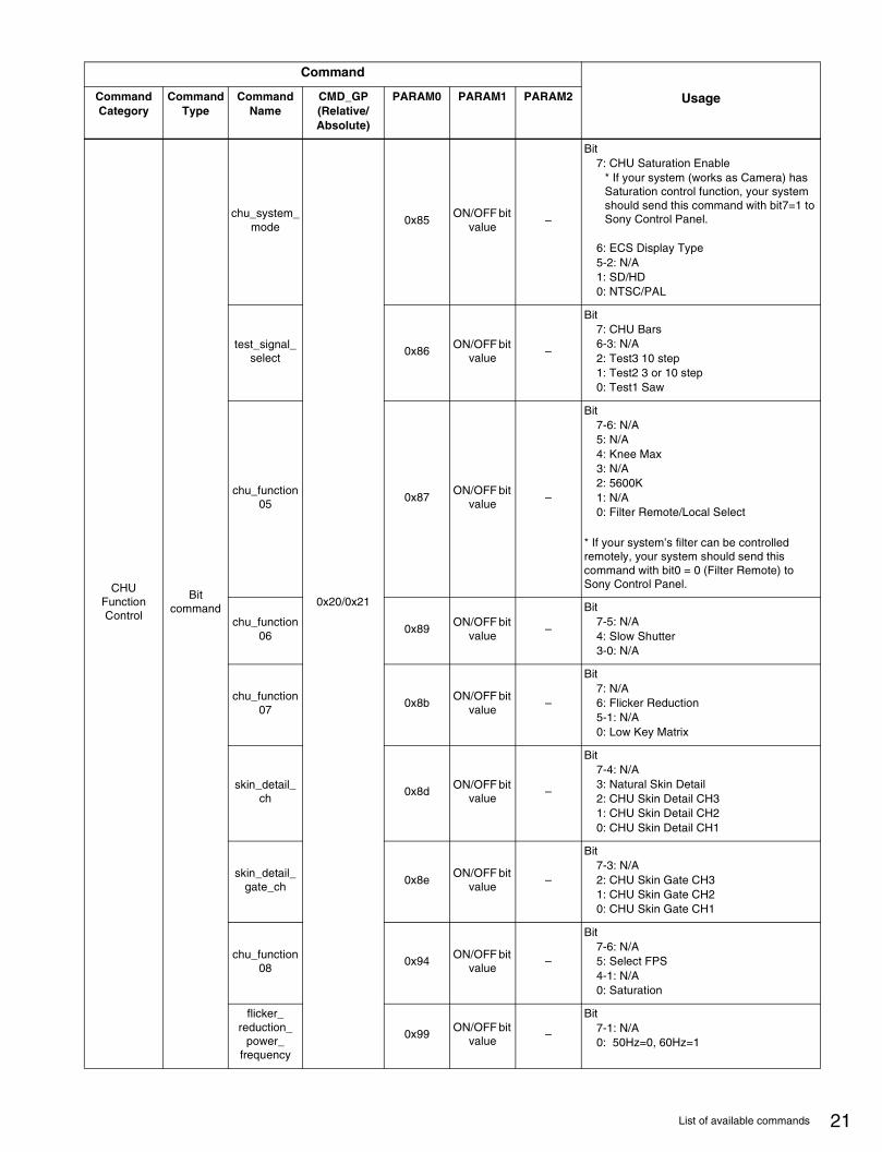
CHUFunctionControl
Bit command
chu_system_mode
0x20/0x21
0x85ON/OFF bit
value–
Bit7: CHU Saturation Enable
* If your system (works as Camera) has Saturation control function, your system should send this command with bit7=1 to Sony Control Panel.
6: ECS Display Type5-2: N/A1: SD/HD0: NTSC/PAL
test_signal_select
0x86ON/OFF bit
value–
Bit7: CHU Bars6-3: N/A2: Test3 10 step1: Test2 3 or 10 step0: Test1 Saw
chu_function05
0x87ON/OFF bit
value–
Bit7-6: N/A5: N/A4: Knee Max3: N/A2: 5600K1: N/A0: Filter Remote/Local Select
* If your system’s filter can be controlled remotely, your system should send this command with bit0 = 0 (Filter Remote) to Sony Control Panel.
chu_function06
0x89ON/OFF bit
value–
Bit7-5: N/A4: Slow Shutter3-0: N/A
chu_function07
0x8bON/OFF bit
value–
Bit7: N/A6: Flicker Reduction5-1: N/A0: Low Key Matrix
skin_detail_ch
0x8dON/OFF bit
value–
Bit7-4: N/A3: Natural Skin Detail2: CHU Skin Detail CH31: CHU Skin Detail CH20: CHU Skin Detail CH1
skin_detail_gate_ch
0x8eON/OFF bit
value–
Bit7-3: N/A2: CHU Skin Gate CH31: CHU Skin Gate CH20: CHU Skin Gate CH1
chu_function08
0x94ON/OFF bit
value–
Bit7-6: N/A5: Select FPS4-1: N/A0: Saturation
flicker_reduction_
power_frequency
0x99ON/OFF bit
value–
Bit7-1: N/A0: 50Hz=0, 60Hz=1
Command
UsageCommand Category
Command Type
Command Name
CMD_GP(Relative/Absolute)
PARAM0 PARAM1 PARAM2
21List of available commands

22
CHUFunctionControl
Bit command
chu_mode_sw00
0x20/0x21
0xa0ON/OFF bit
value–
Bit7: Adaptive Matrix6-0: N/A
chu_mode_sw02
0xa2ON/OFF bit
value–
Bit7-2: N/A1: Adaptive Knee Mode0: N/A
chu_mode_sw03
0xa3ON/OFF bit
value–
Bit7-4: N/A3: Noise Suppression2-0: N/A
chu_mode_sw04
0xa4ON/OFF bit
value–
Bit7-2: N/A1: V Detail Source Mode0: Freq 1001/1000 1001=0 , 1000=1
0xc2ON/OFF bit
value–
Bit7: N/A6: SD Detail5-0: N/A
Word command
white_R
0x22/0x23
0x01 value H value L
Effective size = 10bits
white_G 0x02 value H value L
white_B 0x03 value H value L
master_mod_shd_v_saw
0x04 value H value L
mod_shd_v_saw_R
0x05 value H value L
mod_shd_v_saw_G
0x06 value H value L
mod_shd_v_saw_B
0x07 value H value L
master_flare 0x08 value H value L
flare_R 0x09 value H value L
flare_G 0x0a value H value L
flare_B 0x0b value H value L
detail_limiter 0x0c value H value L
detail_white_limiter
0x0d value H value L
detail_black_limiter
0x0e value H value L
master_black_gamma
0x10 value H value L
black_gamma_R
0x11 value H value L
black_gamma_G
0x12 value H value L
black_gamma_B
0x13 value H value L
Command
UsageCommand Category
Command Type
Command Name
CMD_GP(Relative/Absolute)
PARAM0 PARAM1 PARAM2
List of available commands

CHUFunctionControl
Word command
master_knee_point
0x22/0x23
0x14 value H value L
Effective size = 10bits
knee_point_R
0x15 value H value L
knee_point_G
0x16 value H value L
knee_point_B
0x17 value H value L
master_knee_slope
0x18 value H value L
knee_slope_R
0x19 value H value L
knee_slope_G
0x1a value H value L
knee_slope_B
0x1b value H value L
master_gamma
0x1c value H value L
gamma_R 0x1d value H value L
gamma_G 0x1e value H value L
gamma_B 0x1f value H value L
master_white_clip
0x20 value H value L
white_clip_R 0x21 value H value L
white_clip_G 0x22 value H value L
white_clip_B 0x23 value H value L
flicker_reduce_gain
_m0x24 value H value L
flicker_reduce_ofs_
m0x28 value H value L
ecs_frequency
0x41 value H value L
evs_data 0x42 value H value L
skin_detail_phase
0x43 value H value L
skin_detail_width
0x44 value H value L
chu_optical_level
0x47 value H value L Effective size = 15bits unsigned
skin_detail2_phase
0x54 value H value L
Effective size = 10bits
skin_detail2_width
0x55 value H value L
skin_detail3_phase
0x56 value H value L
skin_detail3_width
0x57 value H value L
Command
UsageCommand Category
Command Type
Command Name
CMD_GP(Relative/Absolute)
PARAM0 PARAM1 PARAM2
23List of available commands

24
CHUFunctionControl
Word command
iris
0x22/0x23
0x60 value H value L Effective size = 12bits unsigned
detail_level 0x9b value H value L
Effective size = 10bits
detail_crispening
0x9c value H value L
detail_mix_ratio
0x9d value H value L
detail_HV_ratio
0x9e value H value L
H_detail_HL_ratio
0x9f value H value L
detail_level_depend
0xa0 value H value L
skin_detail_level
0xa1 value H value L
skin_detail_sat
0xa2 value H value L
matrix_GR_R
0xa3 value H value L
matrix_BR_R
0xa4 value H value L
matrix_RG_G
0xa5 value H value L
matrix_BG_G
0xa6 value H value L
matrix_RB_B 0xa7 value H value L
matrix_GB_B
0xa8 value H value L
master_black
0xa9 value H value L Effective size = 12bits signed
black_R 0xaa value H value L
Effective size = 10bits
black_G 0xab value H value L
black_B 0xac value H value L
knee_sat_slope
0xae value H value L
knee_aperture
0xaf value H value L
comb_filter 0xb0 value H value L
low_key_clip_level
0xb7 value H value L
adaptive_knee_point
0xc4 value H value L
adaptive_knee_slope
0xc5 value H value L
slim_detail 0xc6 value H value L
skin_detail2_level
0xc7 value H value L
skin_detail2_sat
0xc8 value H value L
Command
UsageCommand Category
Command Type
Command Name
CMD_GP(Relative/Absolute)
PARAM0 PARAM1 PARAM2
List of available commands

CHUFunctionControl
Word command
skin_detail3_level
0x22/0x23
0xc9 value H value L
Effective size = 10bits
skin_detail3_sat
0xca value H value L
chu_saturation
0xd2 value H value L
white_color_temp_ctrl
0xdc value H value L
chu_color_temp_
balance0xde value H value L
select_fps 0xdf value H value L
SD_detail_level
0xe0 value H value L
SD_detail_crispening
0xe1 value H value L
SD_detail_H/V_ratio
0xe2 value H value L
SD_detail_limitter
0xe3 value H value L
SD_detail_white_limitter
0xe4 value H value L
SD_detail_black_limitter
0xe5 value H value L
SD_detail_frequency
0xe6 value H value L
SD_detail_level_
depend0xe7 value H value L
SD_detail_detail_comb
0xeb value H value L
master_white_gain
0xf2 value H value L
CHUAutoSetup
Control
Other command
auto_setup 0x25 TYPEEXECUTE / STATUS
–
TYPE0x00: Status query0x01: Auto White Balance0x02: Auto Black Balance0x03: Auto Level0x07: Skin Detail Auto Hue(CH1)0x0A: Skin Detail Auto Hue(CH2)0x0B: Skin Detail Auto Hue(CH3)
EXECUTE / STATUS0x00: Status query0x01: Start0x02: Break0x03: OK0x04: NG0x05: Under execution0x06: Standby0x07: Cancel Standby0x08: Reset Status0x09: Busy
Command
UsageCommand Category
Command Type
Command Name
CMD_GP(Relative/Absolute)
PARAM0 PARAM1 PARAM2
25List of available commands

26
CHU SceneFileControl
Other command
scene_file_control
0x27EXECUTE / STATUS
0x03 FILE_NO
EXECUTE / STATUS0x00: Canceling the operation (Cancel)0x01: Initialization (Formatting)0x02: Calling0x03: Saving0x04: Erasing0x05: Canceling the call0x06: Status request0x07: File call in progress0x08: This file contains data that is not called0x09: There is a file but no data0x0a: The corresponding file does not exist0x0b: Transmission of number of files0x0c: File operation is not possible at present. Or, this command was transmitted while file operation was not possible for some reason.
FILE_NO1-32 (Decimal)
UtilityOther
commandchu_switch_with_mask
0x29 SW_ADDR SW_DATAMASK_DATA
Only absolute control. This command helps you to send Bit-type command absolutely.PARAM0-1 are same as an absolute Bit command. PARAM2 is masking datum for PARAM1.Each bit of PARAM1 is enabled when PARAM2 bit set to 1.
CCUFunctionControl
Bit command
ccu_function00
0x40/0x41
0x10ON/OFF bit
value–
Bit7: N/A6: CCU Skin Gate5-2: N/A1: Chroma0: CCU Bars
ccu_function01
0x12ON/OFF bit
value–
Bit7-3: N/A2: Mono1-0: N/A
preview_control
0x31ON/OFF bit
value–
Bit7-1: N/A0: Preview
Inc/Dec command
SD_letter_box_mode
0x40INC/DEC
value–
Bit5-000: 16:901: 15:902: 14:903: 13:904: 12:9
Bit command
SD_function02
0xc2ON/OFF bit
value–
Bit7: N/A6: SD Detail5: SD User Matrix4: SD Preset Matrix3-0: N/A
SD_function03
0xc3ON/OFF bit
value–
Bit7: N/A6: SD Multi Matrix5: N/A4: SD Matrix3-0: N/A
Command
UsageCommand Category
Command Type
Command Name
CMD_GP(Relative/Absolute)
PARAM0 PARAM1 PARAM2
List of available commands
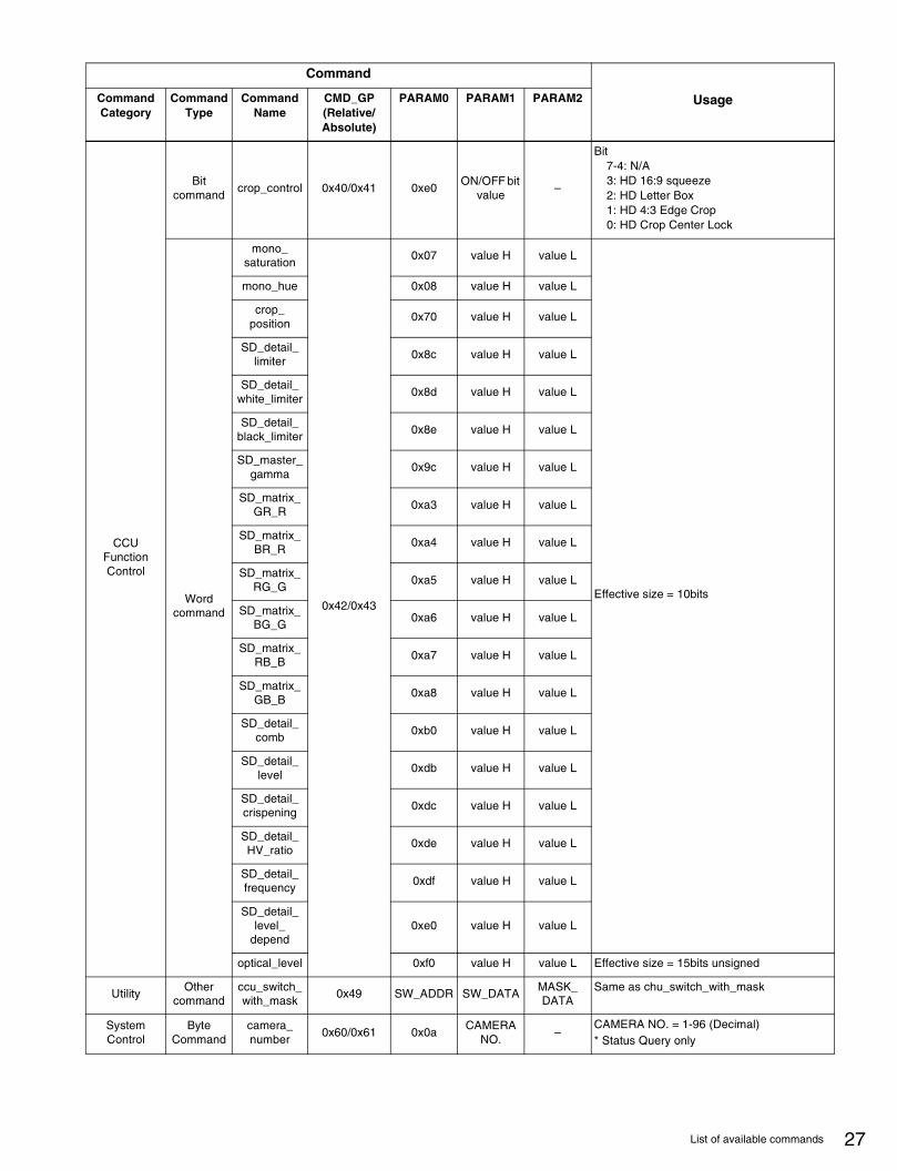
CCUFunctionControl
Bit command
crop_control 0x40/0x41 0xe0ON/OFF bit
value–
Bit7-4: N/A3: HD 16:9 squeeze2: HD Letter Box1: HD 4:3 Edge Crop0: HD Crop Center Lock
Word command
mono_saturation
0x42/0x43
0x07 value H value L
Effective size = 10bits
mono_hue 0x08 value H value L
crop_position
0x70 value H value L
SD_detail_limiter
0x8c value H value L
SD_detail_white_limiter
0x8d value H value L
SD_detail_black_limiter
0x8e value H value L
SD_master_gamma
0x9c value H value L
SD_matrix_GR_R
0xa3 value H value L
SD_matrix_BR_R
0xa4 value H value L
SD_matrix_RG_G
0xa5 value H value L
SD_matrix_BG_G
0xa6 value H value L
SD_matrix_RB_B
0xa7 value H value L
SD_matrix_GB_B
0xa8 value H value L
SD_detail_comb
0xb0 value H value L
SD_detail_level
0xdb value H value L
SD_detail_crispening
0xdc value H value L
SD_detail_HV_ratio
0xde value H value L
SD_detail_frequency
0xdf value H value L
SD_detail_level_
depend0xe0 value H value L
optical_level 0xf0 value H value L Effective size = 15bits unsigned
UtilityOther
commandccu_switch_with_mask
0x49 SW_ADDR SW_DATAMASK_DATA
Same as chu_switch_with_mask
System Control
Byte Command
camera_number
0x60/0x61 0x0aCAMERA
NO.–
CAMERA NO. = 1-96 (Decimal)* Status Query only
Command
UsageCommand Category
Command Type
Command Name
CMD_GP(Relative/Absolute)
PARAM0 PARAM1 PARAM2
27List of available commands

28
Format list* If your system works as Camera that need to display a Sutter value on Sony Control Panel, your system must send Format value
with these commands in advance.
Video Format
chu_mode04(0xa4)
format_mode (0x91) chu_system_mode (0x85)
bit0 bit5 bit4 bit3 bit2 bit1 bit0 bit6 bit1 bit0
1035/59.94I 0 * * * * * * 0 1 0
1035/60I 1 * * * * * * 0 1 0
PAL * * * * * * * 0 0 1
NTSC * * * * * * * 0 0 0
NTSC 29.97P 0 0 1 0 0 0 0 1 0 0
NTSC 23.98P 0 0 1 0 0 1 0 1 0 0
NTSC 59.94I 0 0 0 0 0 0 0 1 0 0
PAL 50I 1 0 0 0 0 0 1 1 0 1
PAL 25P 1 0 1 0 0 0 1 1 0 1
1080/60I 1 0 0 0 0 0 0 1 1 0
1080/59.94I 0 0 0 0 0 0 0 1 1 0
1080/30P 1 0 1 0 0 0 0 1 1 0
1080/29.97P 0 0 1 0 0 0 0 1 1 0
1080/50I 1 0 0 0 0 0 1 1 1 0
1080/25P 1 0 1 0 0 0 1 1 1 0
1080/24P 1 0 1 0 0 1 0 1 1 0
1080/23.98P 0 0 1 0 0 1 0 1 1 0
1080/60P 1 0 1 0 1 0 0 1 1 0
1080/59.94P 0 0 1 0 1 0 0 1 1 0
1080/50P 1 0 1 0 1 0 1 1 1 0
List of available commands

CNA-1 (SY)4-431-827-01(1) © 2012
Sony Corporation