
Calculation No. 11-2357-C-003, Revision No. 5, 'Evaluation of … · 2014-02-11 · CALC. NO. I...
45
ENCLOSURE 1 Evaluation of Repair Sleeve Assemblies, Calculation 11-2357-C-003 Calvert Cliffs Nuclear Power Plant, LLC January 29, 2014
Transcript of Calculation No. 11-2357-C-003, Revision No. 5, 'Evaluation of … · 2014-02-11 · CALC. NO. I...

ENCLOSURE 1
Evaluation of Repair Sleeve Assemblies, Calculation 11-2357-C-003
Calvert Cliffs Nuclear Power Plant, LLCJanuary 29, 2014

aLTRanEvaluation of Repair Sleeve Assemblies
11-2357-C-003
Constellation Energy
Calvert Cliffs Nuclear Power Plant
5 1/13/14 See Page 4 Y. Gan / N Rao H Lu W Mcbrine J Gabriel
4 3/12/2013 See Page 4 H Lu A Chock R W Hammelmann
3 2/17/12 See Page 4 E Wapner R W Hammelmann R W Hammelmann
2 2/15/12 See Page 4 E Wapner R W Hammelmann R W HammelmannA Chock/
1 1/26/12 See Page 4 Y Gan/E Wapner R W Hammelmann R W Hammelmann
0 1/4/12 See Page 4 H Lu W Mcbrine R W Hammelmann
Rev No. Date Revision Description Prepared Checked Independent Approved/IReIIv Reviewer Date
aLTRan

CALC. NO. 11-2357-C-003
aLTRaln INDEPENDENT REVIEW REV. NO.: 5 PAGE 2 OF 30
CLIENT/PROJECT Constellation Energy/ Calvert Ciffs Nuclear Power Plant (10 CFR 50, Appendix B) PREP N Rao DATE 118/14
CALC. TITLE Evaluation of Repair Sleeve Assemblies CHK'D H Lu DATE 1/8/14
Report RecordReport No.: 11-2357-C-003 Rev. No.: 5 Sheet No. 2
10CFR50, Appendix B Applies: 1A] Total Pages: 44
Title: Evaluation of Repair Sleeve Assemblies
Client: Calvert Cliffs Nuclear Power Plant Facility: Constellation Energy
Revision Description:
Revised to incorporate system design temperature changes from 95 F to 200 F.
Computer runs are identified on a Computer File Index: Yes E1 N/A M]
Error reports are evaluated by: Date:
Computer use is affected by error notices. No 0l, Yes LI (if yes, attach explanation)
Prevarer(j _ Date , Date- /-~ 1/13/14 1/13/14
Independent Review: Independent Review is performed in accordance with AOP 3.4 as indicated below.9 Design review as documented on the following sheet or
I] Alternate calculation as documented in attachment or
[] Qualification testing as documented in1 attachment or
Independent Reviewer: L&r////S4- r' 2'a' _ Date: 1/13/14
APPROVAL FOR RELEAS:
LEAD ENGINEER: Date: 1/13/14

CALC. NO. I 1-2357-C-003
aLTRan INDEPENDENT REVIEW REV. NO.: 5 PAGE 3 OF 30
CLIENT/PROJECT Constellation Energy/ Calvert Cliffs Nuclear Power Plant (10 CFR 50, Appendix B) PREP N Rao DATE 1/8/14
CALC. TITLE Evaluation of Repair Sleeve Assemblies CHK'D H Lu DATE 1/8/14
Independent Review Considerations (in accordance with EOP 3.4)
1.
2.
3.
4.5.6.7.8.9.10.11.
12.13.14.15.16.17.
18.19.20.
The inputs come from an appropriate and controlled source, and are clearly referenced.The inputs from uncontrolled sources or assumptions are properly justified and documented.The inputs or assumptions that are not adequately justified are identified for later confirmation.Design, analysis, testing, examination, and acceptance criteria are specified and complied with.Appropriate interface control was administered during the process of this report.The computer programs used are authorized for use and/or properly verified.Applicable codes, standards, or regulatory requirements are properly specified & complied with.The specified tests & examinations were performed by personnel with appropriate qualifications.All tests and examinations were performed in accordance with written procedures.Specimens are controlled by identification number and their traceability is maintained.The calibration of instrumentation is acceptable and properly recorded.The instruments that are used are recorded by name and identification number.The report is neat and legible and suitable for reproduction.The formatting and technical requirements of applicable procedures are complied with.Critical numerical computations have been checked in detail.The endorsements of all originators and verifiers have been properly recorded.Appropriate construction, operation, and/or maintenance considerations have been considered.The conclusions satisfy stated objectives, and they are consistent with the input.All material specified are compatible with their service environment.Procedural requirements for report revisions and subsequent reviews are complied with.
Initials
".-4
A/ A 't
,r %0-1
W01L
Clarify significant comments:
All comments are resolved and incorporated into the calculation except as noted here:
O • , ,,o , A - 1 / 1 3 / 1 4 C u ctde/ e v e w r C nc D 1 3 / 1 4
Oei~inator's Concurrence Date Independent R~eviewer's Concurrence Date

CALC. NO. 11-2357-C-003
aLTRRan REVISION DESCRIPTION REV. NO.:5 PAGE4OF30
CLIENT/PROJECT Constellation Energy/ Calvert Cliffs Nuclear Power Plant (10 CFR 50, Appendix B) PREP N Rao DATE 1/8/14
CALC. TITLE Evaluation of Repair Sleeve Assemblies CHK'D H Lu DATE 1/8/14
Rev. No. Description0 OriginalI Revised to add section 4.6.4 (sheet 35A); Modified conclusions and reference
(sheet 41, 42 and 44). Updated sheets 6, 7, 10, 11, 24, 30, 33 and 34 due tocustomer comments. Also replaced cover sheet, report record (pg 2), verificationsheet (pg 3), revision description (pg 4).
2 Revised hoop stress and minimum wall thickness calculations to include systemdesign pressure. Added CCNPP Civil and Structural documentation to allowableseismic axial acceleration calculation. Cleaned up calculation.
3 Revised hoop stress and minimum wall thickness calculations using max installpressure instead of long term contact pressure. Revised Sh. Minimum contactpressure calculations were revised to neglect, and not subtract, the designpressure. Updated sections include: 3.4, 4.1.5 & 4.1.6, 4.2.1 & 4.2.2, 4.3.2, 4.4.2& 4.6.4. All conclusions updated with revised values.
4 Complete revision to incorporate changes in response to owner's comments.Removed references to gray cast iron pipe, which is out of scope.
5 Revised to incorporate system design temperature changes from 95 F to 200 F. I

CALC. NO. 11-2357-C-003
OLTRan REV. NO.: 5 PAGE 5 OF 30
CLIENT/PROJECT Constellation Energy/ Calvert Cliffs Nuclear Power Plant (10 CFR 50, PREP N Rao DATE 1/8/14Appendix 1B)
CALC. TITLE Evaluation of Repair Sleeve Assemblies CHK'D H Lu DATE 1/8/14
Table of Contents
Title Page ..................................................................................................................................................... 1Verification .................................................................................................................................................. 2Revision Description .................................................................................................................................... 3Table of Contents ......................................................................................................................................... 4
1.02.03.0
3.13.23.3
4.05.06.0
PU RPO SE ........................................................................................................................................ 5M ETH O D O LO G Y .......................................................................................................................... 6INPUT, ASSUMPTIONS, AND CLARIFICATIONS ...................................................................
Input 7Assumptions 9Clarifications 10
REFEREN CES ............................................................................................................................... 10CA LCU LA TION S / A N A LY SIS ................................................................................................... 11RESULTS / CO N CLU SIO N S ................................................................................................... 28
ATTACHMENTS
Attachment AAttachment BAttachment CAttachment D
Design Sketches (4 pages)Miscellaneous Information (5 pages)Email Correspondence (3 pages)Miscellaneous Calvert Cliffs Documents (2 pages)
5
CALC. NO. 11-2357-C-003
aLTRanl REV. NO.: 5 PAGE 6 OF 30
CLIENT/PROJECT Constellation Energy/ Calvert Cliffs Nuclear Power Plant (10 CFR 50, PREP N Rao DATE 1/8/14Appendix B)
CALC. TITLE Evaluation of Repair Sleeve Assemblies CHK'D H Lu DATE 1/8/14
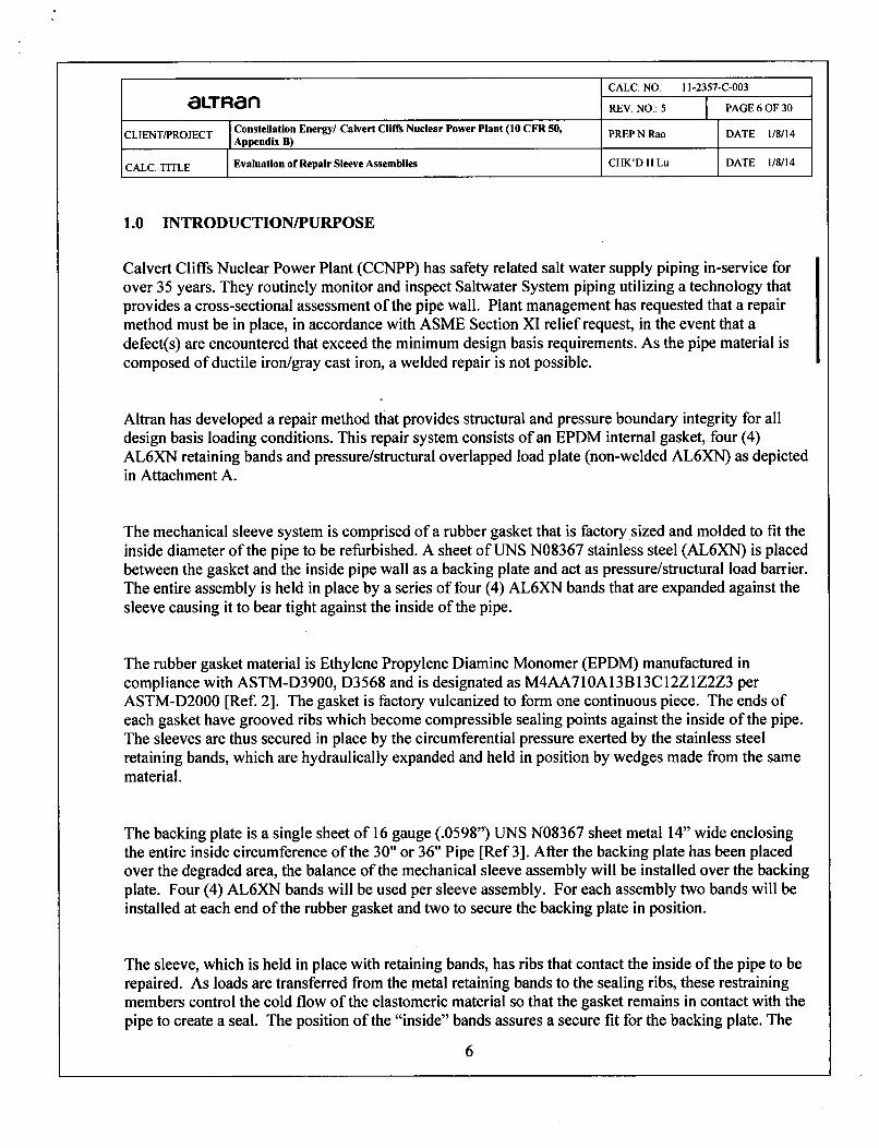
1.0 INTRODUCTION/PURPOSE
Calvert Cliffs Nuclear Power Plant (CCNPP) has safety related salt water supply piping in-service forover 35 years. They routinely monitor and inspect Saltwater System piping utilizing a technology thatprovides a cross-sectional assessment of the pipe wall. Plant management has requested that a repairmethod must be in place, in accordance with ASME Section XI relief request, in the event that adefect(s) are encountered that exceed the minimum design basis requirements. As the pipe material iscomposed of ductile iron/gray cast iron, a welded repair is not possible.
Altran has developed a repair method that provides structural and pressure boundary integrity for alldesign basis loading conditions. This repair system consists of an EPDM internal gasket, four (4)AL6XN retaining bands and pressure/structural overlapped load plate (non-welded AL6XN) as depictedin Attachment A.
The mechanical sleeve system is comprised of a rubber gasket that is factory sized and molded to fit theinside diameter of the pipe to be refurbished. A sheet of UNS N08367 stainless steel (AL6XN) is placedbetween the gasket and the inside pipe wall as a backing plate and act as pressure/structural load barrier.The entire assembly is held in place by a series of four (4) AL6XN bands that are expanded against thesleeve causing it to bear tight against the inside of the pipe.
The rubber gasket material is Ethylene Propylene Diamine Monomer (EPDM) manufactured incompliance with ASTM-D3900, D3568 and is designated as M4AA71OA13Bl3C12Z1Z2Z3 perASTM-D2000 [Ref. 2]. The gasket is factory vulcanized to form one continuous piece. The ends ofeach gasket have grooved ribs which become compressible sealing points against the inside of the pipe.The sleeves are thus secured in place by the circumferential pressure exerted by the stainless steelretaining bands, which are hydraulically expanded and held in position by wedges made from the samematerial.
The backing plate is a single sheet of 16 gauge (.0598") UNS N08367 sheet metal 14" wide enclosingthe entire inside circumference of the 30" or 36" Pipe [Ref 3]. After the backing plate has been placedover the degraded area, the balance of the mechanical sleeve assembly will be installed over the backingplate. Four (4) AL6XN bands will be used per sleeve assembly. For each assembly two bands will beinstalled at each end of the rubber gasket and two to secure the backing plate in position.
The sleeve, which is held in place with retaining bands, has ribs that contact the inside of the pipe to berepaired. As loads are transferred from the metal retaining bands to the sealing ribs, these restrainingmembers control the cold flow of the elastomeric material so that the gasket remains in contact with thepipe to create a seal. The position of the "inside" bands assures a secure fit for the backing plate. The
6

strength and resilience of the sleeve assembly will provide a durable and reliable protective shield insidethe pipe against the erosive effects of water flowing at varying rates.
The purpose of this calculation is to
" Qualify the internal mechanical sleeve assembly as a contingent repair for the safety relatedservice water supply piping of ductile iron only at the Calvert Cliffs Nuclear Power Plant. Theloading conditions considered include installation, seismic (SSE), pipe movement, fatigue andnormal operation.
" The assembly will be qualified for one abnormal loading condition, in which the upstream bandis lost. Further, the backing plate has been reviewed to assess itseffect on pressure boundaryenhancement,
" Calculate the maximum flaw size based on the qualification.
2.0 METHODOLOGY
This calculation qualifies the sleeve assemblies for loads applied during installation and operation.The analysis uses methods of classical mechanics. In addition, the applied hoop stress caused bythe retaining bands on the host pipe was qualified. This calculation will also determine if theretaining bands are sufficient to hold the sleeve in place and qualify the backing plate that willrepair the defect. This calculation will also determine if the retaining bands shall be sufficient forthe 50 psig design pressure of the Service Water (SW) cooling system. In addition, the calculationwill determine the maximum diameter of a postulated circular flaw in the ductile iron pipe basedon the ability of the AL6XN backing plate to resist the internal pressure load.
The methodology and calculations performed for the internal repair sleeve system assumes anyrepairs are made in a straight length of pipe. The proposed repair system is not designed to be usedin pipe elbows or across mitered (or misaligned) joints. With the construction of the ductile ironpipe, the straight sections subject to repair may include a bell and spigot joint, which is consideredacceptable. The design of pressure integrity of these type bell & spigot joints are solely dependentof the V-Gasket that is located between the OD of the pipe spigot and the ID of the bell and is heldin place by the slip-on mechanical flange. The inside surfaces of the joined pipe should meet withno appreciable gap and require no special attention upon installation of a repair sleeve. The use ofthe sleeve repair system in the joint area is considered consistent with the design basis calculationfor the repair provided it does not exceed the dimensional restrictions for the deteriorated area.
7

aLT Ran Calvert Cliffs Page: 8 of 30
SCUNS Evaluation of Repair Sleeve By: Y.GaniNRao Date: 1/8/14Calc. No: 11-2357-C-003, Chk: H Lu Date: 1/8/14
Rev: 5
3.0 Input, Assumptions and Clarifications
3.1 Input
3.1.1 System Piping Parameters - Pipe Specification for 30"/36" Pipes
30in 36in
Pine Outside Diameter Dpo- 30 := 32.00in Dpo_3 6 := 38.30in
Pipe Wall Thickness
Pipe Inside Diameter
Piping Buried Location
Earth Weight above Buried Pipe
Pipe Materials
tp_30 := 0.550in
Dp0 Dp0_30 - 2tp_30
Dp 030.90. in
H.. 30:= 1 1.4ft
tp_36 := 0.630in
Dpi_36 := Dpo_36 - 2tp_6
Dpi 36 = 37.04-in
Hma 36 := 11.7ft
[Ref. 19]
[Ref. 19]
[Ref.3]
[Ref.3]lbfWarth := 120- 3
ft 3
Ductile Iron : Class LC, USAS A21.51-1981[24]. Material ASTM A377, Joint Class 4 [16-18]
Coefficient of Linear - 6 in[Thermal Expansion nDI := 6.2-10 .[Ref.19], Attachment Bin. F
Yield Stress Sy-DI := 42000psi [Ref. 23]
3.1.2 System Design Parameters
Design Pressure
Design Temperature Range(30 'F to 200 °F), Therefore theAT is:
ATIOW= 30 *F - 70 'F = -40 °F
AThigh =200 °F - 70 °F = 130 °F
Maximum System Flow Rate
Pd:= 50psi [Ref. 17]
The assumed installation temperature is 70 °F, Assumption 13.
[Ref. 17]
ATsw:= (40)30}F
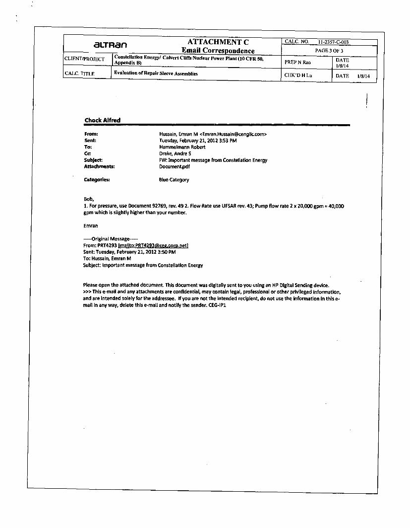
qsys .= 40000 galmin
[Ref.22 ], Attachment C
8

I ~ Page: 9 of303LT Ran Calvert Cliffs P
SaCLUMNm Evaluation of Repair Sleeve By: Y.Gan/NRao Date: 1/8/14Calc. No: 11-2357-C-003, Chk: H Lu Date: 1/8/14
Rev: 5
Whs:= 110*lbf
- 3 lbIlf_70F := 0.658.10 ft. sec
lbPwtr_70F := 62-3--
ft13
The weight of the sleeve assembly as assumed. Assumption 6.
This is the absolute viscosity of water at 70 oF, [Ref. 7]
This is the density water at 70 'F, [Ref. 7]
3.1.3 Internal Sleeve Parameters [Ref. 2, Attachment A].
EPDM Gasket Thickness tws := 0.300in
EPDM Gasket Length Lw, := 19.79in
Retaining Band Thickness trb:= 0.1875in
Retaining Band Width Wrb := 2.Oin
Retaining Band Outside Diameter Drbo_30 := Dpi_30 - 2tws
Drbo_36 := Dpi_36 - 2tws
[Ref. 8], Attachment A
[Ref. 8], Attachment A
[Ref. 2], Attachment A
[Ref. 2], Attachment A
Drbo_30 = 30.30-in
Drbo_36 = 36.44.in
tpt = 0.1875-in
Attachment A
Thickness of the Push Tab
Thickness of the Backing Plate(16 gauge)
tpt := trb
thkback := 0.0598in
3.1.4 Retaining Band and Backing Plate Material Properties
Materials: AL-6XN (UNS N08367), ASTM B688 [Ref. 2, AttachmentA]
Yield Strength SY:= 45000psi
S, := lOOOOOpsi
Sh := M - .Sy,4 Sh= 25000-psi
[Ref. 20]
[Ref. 20]
Coefficient of LinearThermal Expansion
Modulus of Elasticity
Poisson'sRatio
-6 inO rb := 8 .5 -1 0 i n.0 F
in.F
Erb := 28.3- 106. psi
v:= 0.3
[Ref. 6], Attachment B
[Ref.6], Attachment B
Assumption 7
9

Page: lO of 30OcLTRafn Calvert Cliffs
SCLwuINO Evaluation of Repair Sleeve By: Y.Gan/NRao Date: 1/8/14CaIc. No: 11-2357-C-003, Chk: H Lu Date: 1/8/14
Rev: 5
3.1.5 Hydraulic Expander Parameters
Expansion Pressure (gage). HP.This is pressure applied by thehydraulic expander to each of 2800*psi Minimum Assumption 12the 4 retaining bands.Mimu Asmpon1
Maximum [Ref. 10]
Expansion CylinderBore, Standard Enerpac b := 1.69in Assumption 12,#RC 104 Expander Attachment C
3.2 Assumptions
1. The system design temperature is assumed to be 30 OF to 200 °F.
2. The minimum fluid inlet temperature is assumed to be 30 OF
3. The coefficient of friction between the sleeve and the pipe wall is assumed to be:
V:= 0.32 This is based on a rubber belt on steel [Ref. 4, Table 12.2 ]
4. An impact factor of 2 was applied to the hydrodynamic loads to account for the rapid increase in Service Watersupply flow during an accident, as shown in Section 4.3 and 4.5.
5. It is assumed that during the abnormal operating condition, the upstream retaining band will be lostand the sleeve will fold back on itself.
6. The weight of the sleeve assembly is assumed to be 110 lbf.
7. Poisson's ratio forAL-6XN is assumed to be 0.3.
8. Retaining bands on backing plate will be placed on a non-degraded area adjacent to the corrosion area.
9. DELETED
10. A maximum of long term stress relaxation of EPDM gasket is assumed to be 12%. During the repair sleeveinstallation, two expansions of retaining band to the hydraulic pressure will be made. After a minimum of 30 minutesholding following the first expansion, the EPDM gasket is assumed to have made the majority part of long term stressrelaxation. [Ref. 2]
11. Ground water pressure on the outer diameter is assumed to be negligible.
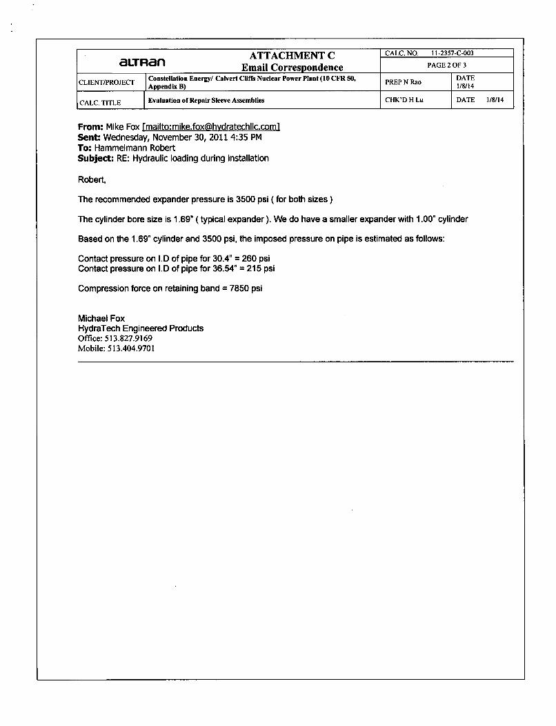
12. The expansion pressure of hydraulic expander at the installation is assumed to be at the range of 2800-3500 psi,with an expansion cylinder bore diameter of 1.69 in. 3500 psi is the maximum pressure defined at the installationprocedure [Ref. 10]. 2800 psi is an administrative low limit assigned byAltran (a conservative value used to ensure aminimum amount of "grip" for the gasket / pipe interface).
13. The installation temperature is assumed to be 70 OF.
14. This calculation qualifies the contingency repair method for ductile iron pipe only (Pipe/Service Class LC-2).
15. The postulate degraded condition for the calculation is a circular flaw.
10

Page: 1l of 30aLTRan Calvert CliffsS•,ujlaN• Evaluation of Repair Sleeve By: Y.Gan/NRao Date: 1/8/14
Calc. No: 11-2357-C-003, Chk: H Lu Date:1/8/14Rev: 5
16. Qualification assumes removal of the cement mortar lining in the area of the contingency repair prior to installation.Exposed ductile iron pipe surfaces shall be coated with Belzona, as a corrosion inhibitor in accordance with Spec.M-600, Class LC [Ref. 21].
17. The density of the material fill is assumed to be 120 lb/ft3 (from Ref. 3).
18.This qualification assumes that the seam of the backing plate is located on the other side of the circular flaw.
3.3 Clarification
None
4.0 References
1. Altran Solutions Proposal No. Pll-2357-00 Final Rev-1, "Contingent Repairs for the 30 Inch and 36 Inch DiameterDuctile Iron Pipe for the Safety Related Service Water System", September 27, 2011.
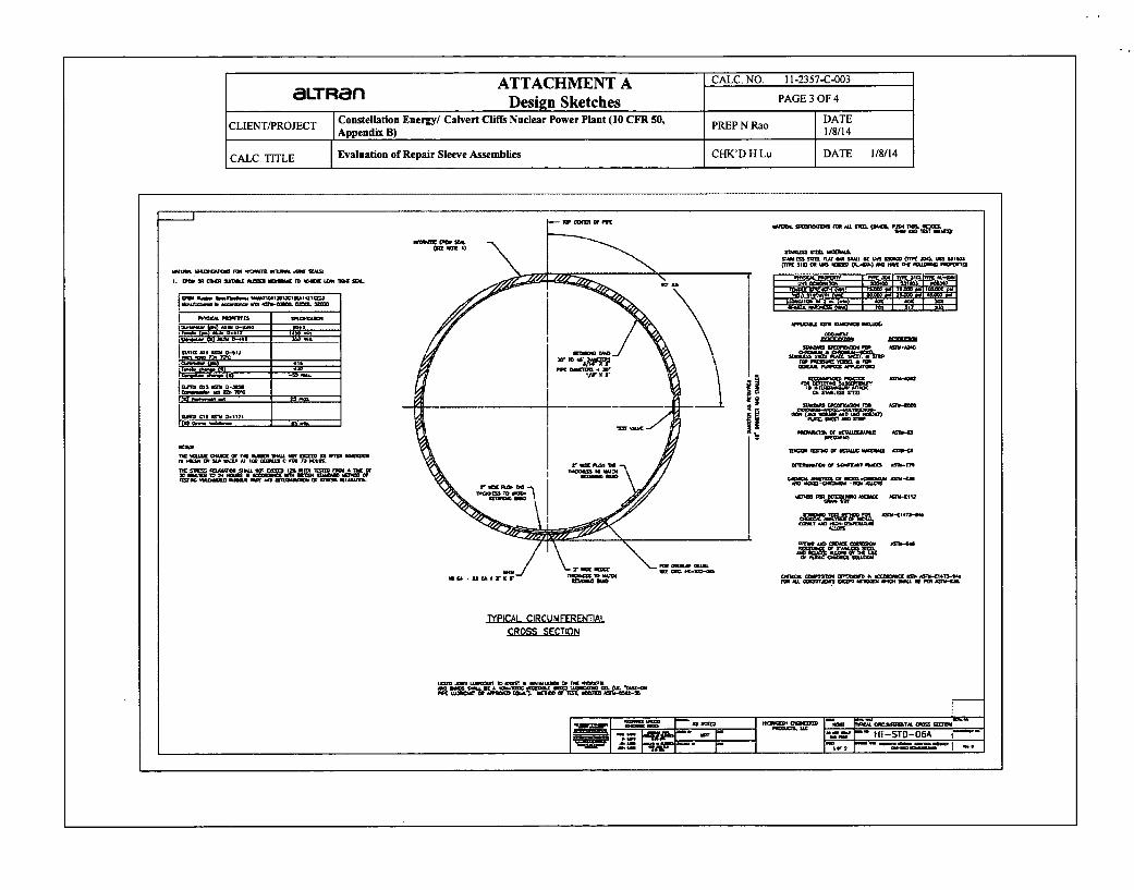
2. HydraTech Engineered Products, Typical Circumferential Cross Section, Drawing No. HT-STD-06A. (see AttachmentA).
3. Calvert Cliffs Nuclear Power Plant, "Minimum Wall Thickness for Salt Water System Underground Piping Per AWWACode", Cal. No. C-92-98, May 11, 1992.
4. M. Lindeburg, Mechanical Engineering Reference Manual, 8th Edition, 1990.
5. USAS B31.1 Power Piping Code, 1967.
6. RathGibson, Physical Properties of 6XN Alloys in the Annealed Condition at -20°F to +100°F,http://www.rathgibson.com/productsbyalloy/super-austeniticl6xn.aspx. (see Attachment B).
7. F. Kreith, Principles of Heat Transfer, 2nd ed., Scranton Pa., Intemational Textbook Co, 1965.
8. HydraTech Engineered Products, Hydratite Double Wide Seal, Drawing No. HT-STD-03. (see Attachment A)
9. Email conversation, From Mike Fox [mailto:[email protected]] to Hammelmann Robert, Subject: RE:Hydraulic loading during installation., November 30, 2011 4:35 PM. (see Attachment C)
10. Altran Solutions Installation Procedure No. 11-2357-P-004 Rev. 1, "Installation Procedure For 30" and 36" DiameterInternal Sleeve Piping Repair Systems", December 2011.
11. Erwin Fried and I.E. Idelchick, Flow Resistance: A Design Guide for Engineers, 2nd Edition, Pages 87 and 85, 1989.(see Attachment B)
12. Marks Standard Handbook of Mechanical Engineers, McGraw Hill, 10th Edition, 1996.
13. ASME Section III, Appendices I, Figure 1-9.2.1., Design Fatigue curve,1989.
14. W.C. Young, and R.G. Budynas, Roark's Formulas for Stress and Strain, 7th Edition, McGraw-Hill, 2002.
15. Calvert Cliffs Nuclear Power Plant, "Civil and Structural Design Criteria", ES-005, Rev 0.
16. CCNPP, "Specification for Salt Water System Pipe and Fittings", Spec. 6750-M-265, Rev. 3. Bechtel, 1969-11-21.
11

Page: 12 of 30
aLTRan Calvert Cliffsoumn=Wo@ Evaluation of Repair Sleeve By: Y.Gan/NRao Date: 1/8/14
CaIc. No: 11-2357-C-003, Chk: H Lu Date: 1/8/14Rev: 5
17. CCNPP, "M-601 Piping Class Summary Sheets", BG&E Document 92769, Rev. 49. (see Attachment D)
18. CCNPP, "Saltwater System", Calvert Cliffs UFSAR, Section 9.5.2.3, Rev. 37.
19. CIPRA, Cast Iron Pipe Research Association (CIPRA) Guide to Installation of Ductile Iron Pipe, 1972. (see AttachmenlB)
20. ASTM Standard B 688 - 96 (Reapproved 2004), Standard Specification for Chromium-Nickel-Molybdenum-Iron (UNSN08366 and UNSN08367) Plate, Sheet, and Strip, 2004.
21. CCNPP, "M-600 Piping Class Summary Sheets", BG&E Document 92767-A, Rev. 44.
22. Email from E. Hussain (CENG) to R. Hammelmann (Altran) dated 2012-02-21, 15:53, Subject: "FW: Importantmessage from Constellation Energy".
23. ANSI A21.50, Amercan National Standard for the Thickness Design of Ductile-Iron Pipe, 1967, 1976.
24. ANSI A21.51, American National Standard for Ductile-Iron Pipe, Centrifugally Cast, 1981.
5.0 Calculation/Analysis
5.1 Loads on the Sleeve Retaining Bands at Installation
The AL6XN retaining bands are installed using a hydraulic expansion device to press the band tight against the sleeve.During installation, a force is applied in opposite directions to each push tab at the break in the band.
This force causes a compressive stress in the band and induces the required contact pressure onto the sleeve. Once theretaining band is expanded to the required hydraulic pressure, a wedge is installed below the long push tab. The hydraulicpressure is then released. After a minimum of 30 minutes, a second expansion of the retaining band is performed to theexpansion tool hydraulic pressure. The abutting edges of the retaining band press against the wedge maintaining the bandand the wedge in compression. The forces in the retaining band cause it to conform to the shape of the host pipe.
5.1.1 Method for Computing Forces and Stresses in the Retaining Bands
The hydraulic expander applies a compressive force to the retaining band at installation, and the area of the force appliedon is the cross sectional area of the retaining band . This force causes a compressive stress that may be calculated via:
Force
Area
CBf. = CB Eq. Where:trbW (1)
fc= Compressive Stress (psi)
CB = Compressive Force Due to Hydraulic Expander (lbf)
trb= Thickness of Retaining Band (in)
Wrb= Width of Retaining Band (in)
12

Page: 13 of 30IaLTRan Calvert Cliffs
SOLntIoNi Evaluation of Repair Sleeve By: Y.Gan/NRao Date: 1/8/14Caic. No: 11-2357-C-003, Chk: H Lu Date: 1/8/14
Rev: 5
In addition, the compressive stress in the band is related to the pressure imposed by the band on the pipe Pcontactusing the hoop stress equation
Pco0 a* D= Eq. (2)2" trb
Substituting Eq. 2 for f, in Eq. 1, then solving for
Pcontact
Where:2
Pcontact 2 - CB Eq. (3)Drbo. Wb Drbo = Retaining Band Outside Diameter (in)
Pcontact = Contact Pressure (psi)
Wrb = Width of Retaining Band (in) = 2.00 in.
CB = Compressive Force Due to Hydraulic Expander (lbf)
5.1.2 Calculation of the Compressive Force in the Retaining Band at Installation
The sleeve retaining bands are installed using the standard #RC104 expander with a 1.69" diameter hydraulic cylinder.The compressive force on the retaining band during installation, CB, is:
[Reference to Section 2.2.5]CBi:= (4".b)'HPi CB is the hoop force imposed on the retaining band by
the hydraulic cylinder during installation.
b = 1.69-in This is the expansion cylinderbore.
(6281 Force on band due to minimum hydraulic expander pressure
CB 6281bf (2800psi)C 7851
Force on band due to minimum hydraulic expander pressure(3500psi)
5.1.3 Calculation of Contact Pressure Between the Retaining Bands, EPDM Elastomer
Gasket and the Pipe
The contact pressure, Pcota at installation is calculated using Eq. 3:
For 30 inch Host Pipe
2CBPcontact_30 --Wrb'rbo_30
( 207> Minimum
(259) Maximum
13

Page: 14 of 30aLTRan Calvert Cliffs
Sa=ulTNE Evaluation of Repair Sleeve By: Y.Gan/NRao Date: 1/8/14Calc. No: 11-2357-C-003, Chk: H Lu Date: 1/8/14
Rev: 5
The long term contact pressure is based on a maximum compression stress relaxation of 12%, (assumption 10).
PcontactLT_30 := (1 - 12 %)Pcontact_30
(" 182 . MinimumPcontactLT_30 = , 2 2 8,,'PsMxiu
(228 Maximum
For 36 inch Host Pipe
2CBPcontact_36 "-
Wrb" Drbo_36
(172• . MinimumPcontact_36 = I 25fSI
(215) Maximum
The long term contact pressure is based on a maximum compression stress relaxation of 12%
PcontactLT_36 : (1 - 12%)-Pcontact_36C 152 )Minimum=co
n t a c t L T 3 6 "1 P s i
( 190 Maximum
5.1.4 Check of Compressive Stress in the Retaining Band
The compressive stress corresponding to the maximum hydraulic expansion pressure is:
CB 1
O'c c ch" Maximum compressive stress in- trb'Wrb 'c_chk = 20936.psi retaining band at installation
C'c chk - 83.7.% of allowable stress
Sh
14

Page: 15 of 30
aL'URan Calvert CliffsSCILLMN8 Evaluation of Repair Sleeve By: Y.Gan/NRao Date: 1/8/14
Calc. No: 11-2357-C-003, Chk: H Lu Date:1/8/14Rev: 5
5.1.5 Determine the Host Pipe Minimum Wall Thickness
The host pipe minimum wall thickness to sustain sleeve assembly loading is determined from ANSI A21.50-1976, Section50-2.2 Step 2 "Design for Internal Pressure" [Ref. 23].
tmin=(Ptotal*Dpipe)/( 2 *Sy-pipe)
For 30 inch Ductile Iron Host Pipe
2(Pcontact_301 + Pd + 1OOpsi + PTHIDI30)-Dpo_30
tDI_30min := 2.(Sy_Dl)
tDI_30ni = 0.3871in This is the minimum host pipe wall thickness for sleeve loading.The host pipe is 30" with a design wall thickness of 0.550 inches.
For 36 inch Ductile Iron Host Pipe
2(Pcontact_36 + Pd + 100psi + PTHIDI36).Dpo_36tDi_36min := 2.(SyDI)
tDI_36min = 0.409.in This is the minimum host pipe wall thickness for sleeve loading.The host pipe is 36" with a design wall thickness of 0.630 inches.
5.2 Compute the Thermal Effects on the Forces in the Retaining Band
5.2.1 Calculation of Thermal Expansion/Compression in the Retaining Bands
Thermal expansion/contraction in the circumferential direction = Ax (assuming that the EPDM is fully compressed). Thisis the difference in expansion between the degraded ductile iron pipe and the AL6XN band.
This calculation is repeated for the hot and cold thermal expansion moduli and the contraction and expansion from 70F to
the minimum and maximum operating temperatures in the system.
For Ductile Iron 30 inch pipe
AXDI30 := arb.7rDrbo 3 0 'ATsw - oDl.7r'Dpi_30.ATsw
-~85xi6 in -6 in
a o= 8.Sx 10- 6. • in oD I= 6.2 x 10 -6
in.F in.F
(-0.0083) Contraction, AT=-40 "FAD130 = ,0.0269 J Expansion, AT=+130 OF
15

c3LT Ran Calvert Cliffs Page: 16 of 30
SCLT="W• Evaluation of Repair Sleeve By: Y.GanINRao Date: 1/8/14Caic. No: 11-2357-C-003, Chk: H Lu Date:1/8/14
Rev: 5
The thermal strain in the retaining band is:
AXD130ethmDI30 '-- --- "iT" rbo_30
-8.71 x 10- 5 Contraction, AT=-40 *FSthm_D130 =II
E. 2.83 x 10- 4 Expansion, AT=+130 'F
Thermal stress uTH in the retaining band due to relative circumferential expansion/contraction of the AL6XN retaining
bands with respect to the pipe resulting from the temperature changes is:
(TTHD130 := 6thm_30Erb
Contraction, AT=-40 *F
UTHD130 (28010 )P5 Expansion, AT=+130 'F
where aTHD130 = thermal stress,
E 2.83 x 10⁷. siCompressive force in the retaining bands due to Alative thermar expansion/contraction:
(-924 Contraction
CTH-D130 := o'TH-D130 "trb 'Wrb C H-0D130 = l Ibf E xpa ction
03004 ), Expansion
The change in contact pressure between the sleeve and the pipe wall due to thermal effects is:
PTHDI030 .-- 0130 PTH D130 = (31 )pWrb- Drbo30 - 99
PTHIm_DI30:= max(I PTHD130 , I PTHD1301iI)
PTHImDI30 = 99.psiNote: this is a forced identity and should be checked with eachcalculation that PTH1 = PTHlm This value is used above for the
PTHI_D130 99 psi Long term operational hoop stress.
The minimum contact pressure between the sleeve and the pipe wall can be computed using the minimum long termcontact pressure and the effects of thermal contraction neglecting the design pressure. This pressure will conservativelycompute the friction force holding the sleeve in place that will be compared to the hydrodynamic forces acting to dislodgethe sleeve.
PcontactLT_300 = 182-psi
Pmin_D130 := PcontactLT_300 + PTHD1300
Pmin D130 = 152'psi
16

aLTRan Calvert Cliffs Page: 17 of 30
SouLMNS Evaluation of Repair Sleeve By: Y.GanINRao Date: 1/8/14Calc. No: 11-2357-C-003, Chk: H Lu Date:1/8/14
Rev: 5
For Ductile Iron 36 inch DiveAXD1 36 =Orb. T.Drbo_3 6 .ATsw - OtDl. .Dpi_36. ATsw
C (-0.0101 .in Contraction
0.0327 1 Expansion
The thermal strain in the retaining band is:AXDI36
- _ 13 "- Drbo_36
Ethm_D136 -8.79 X 10- 5) Contraction
_ 2.86 x 10- 4) Expansion
Thermal stress uTH in the retaining band due to relative circumferential expansion/contraction of the AL6XN retaining
bands with respect to the pipe resulting from the temperature changes is:C -2488> Contraction
CTH-D136 : = Ethm _D136 "Erb O.TH-DI36 = I 8 86 C'psi
_ 8086) Expansion
Compressive force in the retaining bands due to relative thermal expansion/contraction:
CTH-D136 := (TTH-D136"trb'Wrb CTHD136 = lbf Contraction
3 x 10 Expansion
The change in contact pressure between the sleeve and the pipe wall due to thermal effects is:
2 *CTH DI36 -26)Wrb'Drbo_36 - 83
PTHImDI36 := max( PTH_Di3601 1 1PTHDI361 I) PTHIm_DI36 = 83.psi
PTHID136 - 83psi Note: this is a forced identity and should be checked with each
calculation that PTHI = PTH1m This value is used above for the
Long term operational hoop stress.
The minimum contact pressure between the sleeve and the pipe wall can be computed using the minimum long termcontact pressure and the effects of thermal contraction neglecting the design pressure. This pressure will conservativelycompute the friction force holding the sleeve in place that will be compared to the hydrodynamic forces acting to dislodgethe sleeve.
PcontactLT_360 = 152"psi
Pmin_D136 : PcontactLT_360 + PTHD136 0
Pmin_D136 126.psi
17

Page: 18 of 30aLTRan Calvert Cliffs
SunUTWN Evaluation of Repair Sleeve By: Y.Gan/NRao Date: 1/8/14Calc. No: 11-2357-C-003, Chk: H Lu Date: 1/8/14
Rev: 5
5.2.2 Calculation of Minimum Friction Force Between the Sleeve and the Pipe Wall.
The contact force between the sleeve and the pipe wall at each retaining band is:
For Ductile Iron 30 inch Host Pipe
Pmin.D130 = 152-psi Sheet 16
Sheet 9wrb = 2.00.in Drbo 30 = 30.30-in
FcminD130 := PminDl30"Wrb"7T"Drbo_30 F:min_D130 = 28921 . lbf
The minimum friction force is: Ffmin-DI30 := VJFcmin-D130 Ffmin D130 = 9255.1bf
For Ductile Iron 36 inch Host Pipe
Pmin D136 = 126.psi Sheet 17
Wrb = 2.00'in Drbo_36 = 36.44.in Sheet 9
FcminD136 := PminD136"Wrb-trT"Drbo_36 Fcmin_D136 = 28866.1bf
The minimum friction force is: Ffmin-D136 := 1LFcmin-D136 Ffmin D136 9237-1bf
5.3 Calculation of Hydrodynamic Load
The sleeve is held in place by four retaining bands, located at both ends and adjacent to the corrosion area location. Thebands are forced against the sleeve via a hydraulic expander, and a wedge is set into the open gap to hold the retainingband against the sleeve/pipe. The retaining band expansion induces a uniform compressive pressure on the sleeveelastomer. This pressure creates a longitudinal friction force between the elastomer and the pipe. The longitudinalhydrodynamic shear force generated by the fluid flow across the sleeve assembly is opposed by the longitudinal frictionforce. The minimum friction force is computed in Section 4.2.2.
5.3.1 Hydrodynamic Load
For 30 inch Pipe
The pipe inside diameter is:
Dp-0= 30.90-in [Ref. Sect. 2.1]
Conservatively taken as the pipe ID less the sum of the thickness of the sleeves retaining bands and push tab,
Do_3o:= Dpi 30 - 2(tws + trb + tpt) The sleeve thickness is based on a layer of gasket material, the retainingband, and the push tab. Attachment A.
where, tw3=thickness of gasket = 0.300 in [Ref. Sect. 2.2.3, sheet 9]
t,b~thickness of retaining band = 0.1875 in [Ref. Sect. 2.2.3, sheet 9]
tpi=thickness of push tab = 0.1875 in [Ref. Sect. 2.2.3, sheet 9]
18

aLT Ran Calvert Cliffs Page: 19 of 30
SOuLMNO Evaluation of Repair Sleeve By: Y.Gan/NRao Date: 1/8/14Calc. No: 11-2357-C-003, Chk: H Lu Date: 1/8/14
Rev: 5
DO_30 = 29.55. in
The average flow velocity in the orifice is:
Vo 1fj ~ : qsys
V (D°3ft
V ofif _3 = 1 8 .7 - -f
sec
where, qsys= 4 0 0 0 0 gpm [Ref. 22], Attachment C
The average inflow velocity based on the pipe area is:
:=pj qY )(DiWft
Vpipe_30 = 17.1"sec
Determine the Reynolds number for the pipe:
Pwtr 70F Vpipe 30"Dpi_30R e p ip e_ 3 0 := ý P - 0l'"_70F
Repip¢ 30 = 4.172 x 10⁶
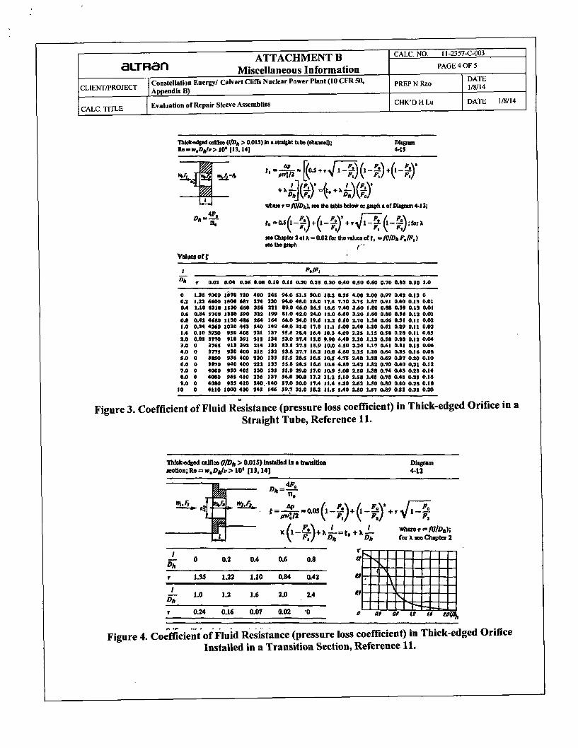
The pressure drop across the sleeve will be calculated by treating it as a thick edged orifice, per (Ref 11, page 87]Attachment B, with a sleeve length of Lws = 19.79.in
:=I0T, 2.(Do_30) cross sectional areaFof30 theoriice- 4 of the orifice.Fpi 30 := 'N -Dp 3)2
- 4 -
Cross-sectional areaof the pipe.
FO 30- 0.915Fpi-3O
FO 30Dh_30 4. •
- 'IT. DO_30
h_30 = 29.55.in
LovrDJ 30--- ODh330
LovrD_30 = 0.67
Use this ratio for the abscissa of the table in Diagram 4-15, [Ref 11].
The hydraulic diameterof the orifice
This is the L/D ratio that is used in the ordinate of the table in Diagram 4-15, [Ref 11].
Note that in diagram 4-12 and 4-15 (as presented in Attachment B), Ko (the hydraulicloss) is represented by the variable ý.
19

3LT Ran Calvert Cliffs Page: 20 of 30
SLT •MN5 Evaluation of Repair Sleeve By: Y.Gan/NRao Date: 1/8/14Calc. No: 11-2357-C-003, Chk: H Lu Date: 1/8/14
Rev: 5
From figure in diagram 4-12 of [Ref 11] T is found from LovrD.
T 30 := 0.672 From figure in diagram 4-12 of [Ref 11] T is found from Lab.
Hydraulic loss for sleeve, represented as a thick edged orifice
Foo3 0 ( Fo-3 02 f F 30 (
K,, 3 0 := 0.5 1 - - + I - - + +T30. I - 1 -- 30_ Fpi_30 ) - Fpi 30 (
FO_30
Fpi_30)[Ref. 11 diagram 4-15]
Ko-30 = 0.067
To determine the pressure drop across the sleeve assembly, certain fluid properties are necessary. The viscosity anddensity of water at 70 deg F is:
"lf 70F = 6.58 x 10⁻⁴ lbft-sec
W1 70F1
wtr 70F :--Pwtr_70F
lbPwtr_70F = 62-3 'b
ft3
[Ref 12, T 3.3.3 & T 6.1.6]
The total pressure drop across the sleeve is
2Vonrif30AP_30 := Pwtr7oF-Ko_30-
_ - - 2 AP_30 = 0.157-psi
The hydrodynamic drag on the sleeve assembly is therefore:
Fdrag3o := AP_30- (i- 34_-- 4 Fdrag_30 = 118-lbf
Since the flow rate increases rapidly in the event of an accident, an impact factor (dynamic load factor) of2 will be applied to the hydrodynamic loads: (See assumption 4)
FHYD_30 := Fdrag_30-2 FHYD 30 = 236-lbf
The hydrodynamic load is much lower than the minimum friction force between the sleeve and pipe, seesec. 4.2.2. Therefore the 30-inch repair is acceptable for hydrodynamic loads.
20

aLTRan Calvert Cliffs Page: 21 of 30
SOLuTON8 Evaluation of Repair Sleeve By: Y.Gan/NRao Date: 1/8/14Calc. No: 11-2357-C-003, Chk: H Lu Date: 1/8/14
Rev: 5
For 36 inch Pipe
The pipe inside diameter is:
Dpi_36 = 37.04.in
The diameter of the orifice (here the term orifice means the ID of the in place retaining ring) is:
tf := tws + trb + tpt
tf = 0.675-in
DO_36:= Dpi_36 -2
tf
The sleeve thickness is based on a layer of gasket material, the retainingband, and the push tab.
DO_36 = 35.69.in
The average flow velocity in the orifice is:
V f 3qsysv°' 6 -O 6) ftVorif 36 = 12.8.-
sec
The average inflow velocity based on the pipe area is:
qsysVpipe_36 := I SS )
Determine the Reynolds number for the pipe:
Pwtr70F' Vpipe 36'Dpi_36
1k 70F
ftVpipe_36= I1.9-
sec
Repipe_36 = 3.481 x 10⁶
The pressure drop across the sleeve will be calculated by treating it as a thick edged orifice, per [Ref 11, page 87],with a sleeve length of Lws = 19.79.in
Fo_36 := 7.(Do_36)4
cross sectional area ofthe orifice. Fpi_36 := 4"(Dpi- 36)2
4Cross-sectional areaof the pipe.
FO 36F- = 0.928
Fpi36Use this ratio for the abscissa of the table in Diagram 4-15, [Ref 11].
21
aLTRan Calvert Cliffs Page: 22 of 30SOLUTONS Evaluation of Repair Sleeve By: Y.Gan/NRao Date: 1/8/14
Calc. No: 11-2357-C-003, Chk: H Lu Date: 1/8/14Rev: 5
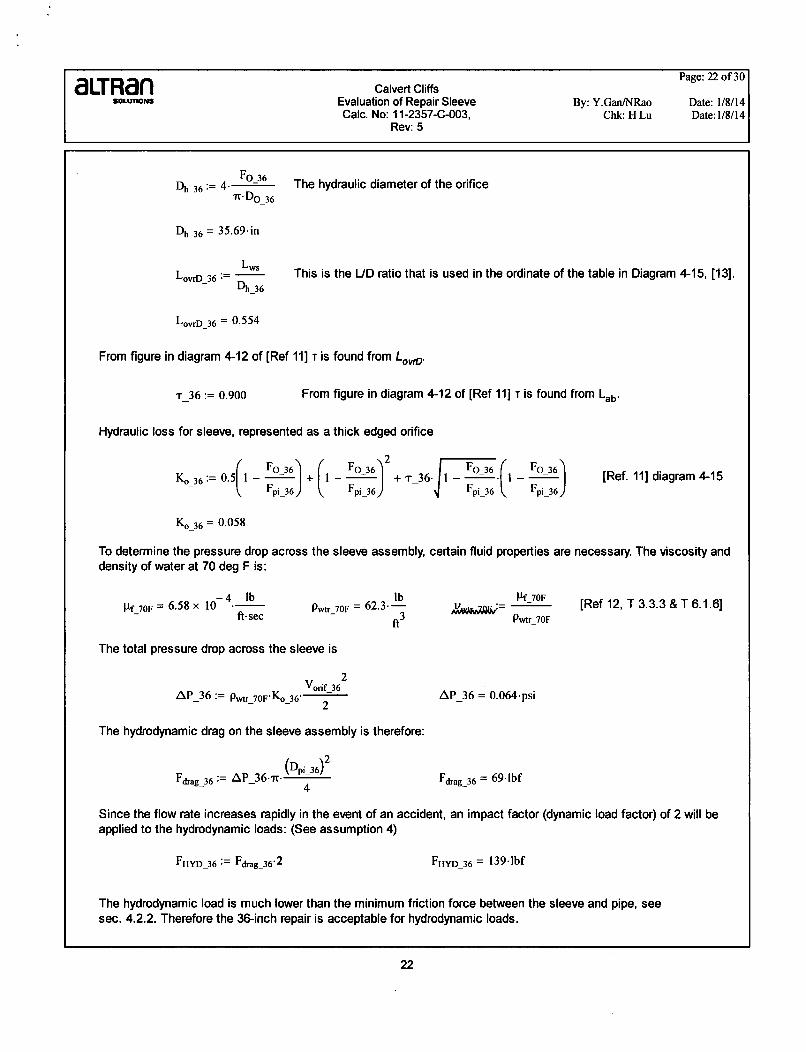
Fo_36Dhb36:= 4 0
- .. DO_36
Oh 36 = 35.69-in
Lws
LowD 36 := O h_36
The hydraulic diameter of the orifice
This is the L/D ratio that is used in the ordinate of the table in Diagram 4-15, [13].
LorD_36 = 0.554
From figure in diagram 4-12 of [Ref 11] T is found from LovrD.
T 36 := 0.900 From figure in diagram 4-12 of [Ref 11] T is found from Lab.
Hydraulic loss for sleeve, represented as a thick edged orifice
"-a_6 o~(i pi-36) (
F°-36 2 F3636 F- 36+_. 6 +° (T Io_
Fpi_36) - F Fpi_36 . Fpi_ 36 j[Ref. 11] diagram 4-15
Ko-36 = 0.058
To determine the pressure drop across the sleeve assembly, certain fluid properties are necessary. The viscosity anddensity of water at 70 deg F is:
-4 lbf 70F = 6.58 x 10 .- s4- ft- seclb
Pwtr_70F = 62.3--
ft3
Pf 70FPwtr 70F
[Ref 12, T 3.3.3 & T 6.1.6]
The total pressure drop across the sleeve is
AP_36 := P.wtr 70FKo3_36 2
AP_36 = 0.064-psi
The hydrodynamic drag on the sleeve assembly is therefore:
(Dpi 36) 2Fdrag36 := AP_36-it- p
4Fdrag_36 = 691lbf
Since the flow rate increases rapidly in the event of an accident, an impact factor (dynamic load factor) of 2 will beapplied to the hydrodynamic loads: (See assumption 4)
FHYD-36 := Fdjrag36,2 FHYD 36 = 139-.bf
The hydrodynamic load is much lower than the minimum friction force between the sleeve and pipe, seesec. 4.2.2. Therefore the 36-inch repair is acceptable for hydrodynamic loads.
22

Page: 23 of 301aLTRan Calvert CliffsSOLiloNS Evaluation of Repair Sleeve By: Y.GanINRao Date: 1/8/14
Calc. No: 11-2357-C-003, Chk: H Lu Date:1/8/14Rev: 5
5.3.2 Check Hydrodynamic Loads Against Friction Force
For 30 inch Ductile Iron PiDe
FfminDl30= 39.2
FHYD_30
For 36 inch Ductile Iron Pipe
>>1 Therefore the sleeve will not be dislodged by flow induced forces.
Ffmin D136- - 66.6 >>1 Therefore the sleeve will not be dislodged by
FHYD_36
5.4 Check of the Sleeve Under Seismic Loads
The seismic load required to cause the sleeve to slip axially within the pipe during a seismic event iscalculated below.
5.4.1 Friction Force Available to Resist Seismic Loading
The friction force available to resist the seismic load: FfSD is calculated by subtracting the
hydrodynamic load: FHYD from the minimum friction force: Ffmin_DI.
flow induced forces.
For 30 inch Ductile Iron Pipe
Ffmin_D130 = 9255.lbf
FfSD130 := FfminD130 - FHYD_30
For 36 inch Ductile Iron Pipe
FSD130 = 9019*lbf
FfminD136 = 9237-lbf
FfSD136 := FfminD136 - FHYD_36 FSD136 = 9099*lbf
23

Page: 24 of 30aLTRan Calvert CliffsGOuLAMa Evaluation of Repair Sleeve By: Y.Gan/NRao Date: 1/8/14
Calc. No: 11-2357-C-003, Chk: H Lu Date:1/8/14Rev: 5
5.4.2 Allowable Sleeve Seismic Axial Acceleration
The allowable local acceleration at the sleeve is a function of the weight of the sleeve and the friction force available toresist the movement. A= F/m
For 30 inch Ductile Iron Pipe
FfSD130ASD130 .
Whs
For 36 inch Ductile Iron Pipe
Whs = 110.lbf
ASD130 = 82.g
FfS0D136As0D136 "--
g
ASD136 = 82.7-g
These calculated allowable accelerations are greater than the maximum ground accelerations required for Class Istructures in the design basis, CCNPP "Civil and Structural Design Criteria", Reference 15.
5.5 Check of Sleeve forAbnormal Loading Condition
The abnormal configuration is assumed to occur if some of the retaining bands were to fail leaving the sleeve held in placeby only one band. The worst case event would occur if one or more of the upstram bands failed, resulting in the sleevefolding back over the remaining downstream band. This would result in an increase in hydrodynamic drag with the potentialfor the sleeve to become dislodged and clog the pipe. The calculation conservatively assumes that the friction force from asingle retaining band resists the hydrodynamic forces.
This condition is determined by first finding the hydraulic load.
For 30 inch Pipe
The pipe inside diameter is:
Dpi_30 = 30.9-in
The diameter of the orifice created by the folded over sleeve is:
tfold := 2tws + trb + tpt
tfold = 0.975-in
Dab_30 : Dpi_30 - 2 tfold
Fab_30 := * (Dab 30)2
- 4
Fab_30Dhab_30 := 4. _
- " Dab_30
The folded over sleeve thickness is based on 2 layers of gasketmaterial, the retaining band, and the push tab.
Dab 30 = 28.95.in
Fpi- 30 = 749.906 in2
Dhab_30 = 28.95-in
Cross-sectional areas of the folded sectionand the pipe.
Hydraulic Diameter of the folded section.
24

aLT Ran Calvert Cliffs Page: 25 of 30
SLT,'iN2 Evaluation of Repair Sleeve By: Y.Gan/NRao Date: 1/8/14Caic. No: 11-2357-C-003, Chk: H Lu Date: 1/8/14
Rev: 5
LwSLab 30 .
Dhab_30
Tab 30 := 0.6384
Lab_30 = 0.684
From figure in diagram 4-12 of [Ref 11] T is found from Lab.
Hydraulic loss for sleeve, represented as a thick edged orifice [Ref 11]Check applicability of formula:
checkl := if(Lab_30 > 0.015,"formula applicable" ,"out of bounds" ) checkl = "formula applicable"
check2 := if(Repipe_3o > 105, 'formula applicable" , "out of bounds") check2 = "formula applicable"
Fab-30 Fab 301 FKab._30:= F 30 + F m + Tab_30" F "
) 30 pi_30
Kabo_30 = 0.103
The pressure drop across the sleeve in the folded over condition is therefore:
Fab 30
Fpi_30 )
2Vpipe_30
A~ab-30 :=Pwtr_7 °F'Kab°-30" 2APab_30 = 0.203-psi
The hydrodynamic drag on the sleeve for the abnormal condition is therefore:
D a 2FHYD ab 30 := 2"APab_30"tr' •~j
FHYD ab 30 = 305.lbf Including an impact factor of 2.
The hydrodynamic load of is much lower than the minimum friction force between the sleeve and pipe, see sec.4.2.2. Therefore the 30-inch repair is acceptable for abnormal hydrodynamic loads.
25

Page: 26 of 30
cLTRan Calvert CliffssOunrngm Evaluation of Repair Sleeve By: Y.Gan/NRao Date: 1/8/14
Calc. No: 11-2357-C-003, Chk: H Lu Date: 1/8/14Rev: 5
For 36 inch Pipe
The pipe inside diameter is:
Dpi_36 = 37.04.in
The diameter of the orifice created by the folded over sleeve is:
,k"ý 2tws + trb + tptThe folded over sleeve thickness is based on 2 layers of gasketmaterial, the retaining band, and the push tab.
tfold = 0.975.in
Dab_36 := Dpi 3 6 -2
tfold
Fab_36 := 4"(Dab 36)2
4
Fab_36Dhab_36 := 4" -
7T Dab_36
Lws
Lab 36Dhab_36
Tab_36 : 0.8764
Dab_36 = 35.09.in
3. 2 Cross-sectional areas of the folded sectionFpi_36 = 1.078 x 10 .in and the pipe.
Dhab_36 = 35.09.in Hydraulic Diameter of the folded section.
Lab_36 = 0.564
From figure in diagram 4-12 of [Ref 11] T is found from Lab.
Hydraulic loss for sleeve, represented as a thick edged orifice (Ref 11]Check applicability of formula:
4w":= if(Lab_36 > 0.015, "formula applicable" , "out of bounds" ) checkI = "formula applicable"
( 5 "f l ap i "t oshU=if( Repij >l0 , formula applicable", "out of bounds" ) hc2="oml plcbe
Kab,0 36 : 0.5- 1 - Fab 36) +Fpi136 )
Fab 36 2
Fpi_36
_ Fab 36 (+ Tab_36- I - I
pi_36
Fab-36")
Fpi_36 )
Kabo_36 = 0.091
The pressure drop across the sleeve in the folded over condition is therefore:
2Vpipe_362
APab_36 := Pwtr_70F" Kabo_36" 2APab_36 = 0.086"psi
26

aLT Ran Calvert Cliffs Page: 27 of 30
,,LUMNT Evaluation of Repair Sleeve By: Y.Gan/NRao Date: 1/8/14Calc. No: 11-2357-C-003, Chk: H Lu Date: 1/8/14
Rev: 5
The hydrodynamic drag on the sleeve for the abnormal condition is therefore:
FHYD ab 36 := 2 -A~ab_3619'a~ FHYD ab_36 = 186.lbf Including an impact factor of 2.
The hydrodynamic load of is much lower than the minimum friction force between the sleeve and pipe, seesec. 4.2.2. Therefore the 36-inch repair is acceptable for abnormal hydrodynamic loads.
For 30 inch Ductile Iron Pipe
FfminDI30- 30.3
FHYDab_30
For 36 inch Ductile Iron Pipe
Ffmin D136- 49.6
FHYD ab_36
no slippage will occur during system operation withthe sleeve folded over.
no slippage will occur during system operation withthe sleeve folded over.
>>1
5.6 Check Backing Plate
5.6.1 Critical flaw size calculated via membrane stress
In as much as the backing plate extends beyond the edge of the flaw and is fixed by the retaining bands and operatingpressure of the system, it is reasonable to treat the reinforcement as a fixed support. Using calculation of the critical flawsize in this manner yields the following result:
22Pd-dflaw. (I + V) 2 Pddflaw 2
Mc = = 1.Ol6dflaw Mr 8- - 1.563dflaw16'4 8'4
Therefore, -max = 6-Mr = 2622.45dflaw2
thkback.Sh
for (Tmax < Sh it is required that, dflaw < = 3.09in2622.45
The critical flaw size is: dflaw := 3.09in
27

Page: 28 of 30aLTRafn Calvert CliffsSOLUM,.NS Evaluation of Repair Sleeve By: Y.Gan/NRao Date: 1/8/14
Calc. No: 11-2357-C-003, Chk: H Lu Date:1/8/14Rev: 5
5.7 Cyclic FatigueThe Stainless Steel type AL6XN retaining bands were evaluated due to the thermal fatigue over the design temperature
range of the system (Section 3.1)
For 30 inch Ductile Iron Pipe
StressRange DI30 := O3THDl30I - ('THD1300 StressRangeD130 = 10475.psi
O'TH_01301 -- OTHDI300
SALT-D130 := 2 SALT_D130 = 5237.psi2
Per inspection of the design fatigue curve (Fig. 1-9.2.1 Ref.13), the number of cycles for
SALT_D130 = 5237.psi is well above 10,000 cycles
For 36 inch Ductile Iron Pipe
Stress-RangeD136 := UTHDI361 - (TTHD1360 StressRangeD136 = 10574-psi
OaTH D1361 -- OTHD360
SALT-D136 := 2 SALTD136 = 5287.psi
Per inspection of the design fatigue curve (Fig. 1-9.2.1 Ref.13), the number of cycles for
SALTD136 = 5287.psi is well above 10,000 cycles
Similarly the pressure cyclic range of 25 psi will induce negligible stress in the components and thus is also wellwithin the Design Fatigue curve.
The EPDM rubber has an elongation of 350% per ASTM 412. This elongation of a non metallic material as well as itscharacteristic for high longevity due to its flexibility provide for the rubber gasket to have a fatigue life greater than the10,000 cycles.
28

Page: 29 of 30aLTRan Calvert CliffsSOLUC•NS Evaluation of Repair Sleeve By: Y.Gan/NRao Date: 1/8/14
CaIc. No: 11-2357-C-003, Chk: H Lu Date: 1/8/14Rev: 5
6.0 Results/Conclusions:
This evaluation of the proposed sleeve assemblies indicates that the assemblies are acceptable for installation in theCalvert Cliffs Nuclear power station Service Water system noting the assumptions stated. Also one retaining band iscapable of resisting hydrodynamic drag loads therefore 4 retaining bands are very conservative. The following summarizethe results of the calculation.
" the maximum compressive stress at the installation in the retaining band is:
'c_chk = 20936.psi
(0 c chkThis is - = 83.7.% of allowable stressSh
* The required minimum wall thickness of the host pipe to support sleeve assemblies, The host pipe is either 30"with a wall thickness of 0.55 inches or 36" with a wall thickness of 0.63 inches.
For 30136 inch Ductile Iron Host Pipe
tDl_30min = 0.387.in
tDI_36min = 0.409.in
* The minimum friction force available force between the sleeve and the pipe wall to resist seismic and hydrualicloads follows. Note that this conservatively considers only one of the four retaining bands.
For 30 inch Ductile Iron Pine
FfS-D130 = 9019.1bf
For 36 inch Ductile Iron Pipe
FfSD136 = 9099.lbf
" For maximum system flow conditions, the hydrodynamic load on the assembly, including an impact of 2, is:
For 30 inch Pipe
FHYD_30 = 236-1bf
For 36 inch Pipe
FHYD_36 = 139.1bf
* If the sleeve inverts, the hydrodynamic load on the sleeve assembly for this abnormal condition is:
For 30 inch Ductile Iron Pipe
FHYD ab_30 = 305.lbf
D130 30.3
FHYD ab_30
29

Page: 30 of 30aLTRan Calvert CliffsGouCm•NO Evaluation of Repair Sleeve By: Y.Gan/NRao Date: 1/8/14
CaIc. No: 11-2357-C-003, Chk: H Lu Date: 1/8/14Rev: 5
For 36 inch Ductile Iron Pipe
FHYD ab_36 = 186.1bf
FfminD136- 49.6
FHYD ab_36
Therefore, since the hydrodynamic load on the sleeve assemblies is significantly less than the friction forcebetween the sleeve and the pipe. The sleeve will remain stationary for the evaluated scenarios.
Note that this conservatively considers only one of the four retaining bands.
* The axial direction seismic acceleration required to dislodge the sleeve assembly is:As_D130 = 82.g AS_D136 = 82.7-g
This is significantly greater than common peak spectra accelerations. Therefore the assembly is seismicallyacceptable.
* The EPDM rubber gasket and retaining bands can withstand 10,000 cyclic movements.
Elongation := 350-% At this elongation 10,000 cycles is not limiting ref ASTM D-412.
SALT_D130 = 5237.psi SALT_D136 = 5287-psi
This alternating stress is well below the endurance limit [Ref. 13].
Calculation Results Summary Table for Ductile Iron Pipe
30 inch Ductile Iron 36 inch Ductile Iron
Maximum compressive stress of yield stressat installation in retaining band
Required minimum wall thickness of thehost pipe to support sleeve assemblies
Minimum friction force available betweenthe sleeve and the pipe wall to resist seismicand hydrualic loads follows
Hydrodynamic load on the assemblywith an impact of 2
Hydrodynamic load on the assembly withan impact of 2 at sleeve invert condition
Axial direction seismic accelerationrequired to dislodge sleeve assembly
Alternating stress due to thermal fatigue
Maximum flaw size at operating pressure
(c= ck=46.5-%
tDI_30mm = 0.387-in
FSD130 =9019.Ibf
FHYD_30 =236*Ibf
FHYIJ-ab_30 = 305 -Ibf
ASD130 = 82*g
SALTD130 = 5237-psi
A"=3.O9in
°'c chkS= 46.5-%
Sy
tDI_36mi = 0.409.in
FfS-D136 = 9099.1bf
FHYD_36 = 139.1bf
FHyDJab_36 = 186-1bf
AS_D136 = 82.7*g
3SALTD136 = 5.287 x 10 .psi
dflaw = 3.09.in
30

ATTACHMENT A CALC. NO. 11-2357-C-003aLT Ran Design Sketches PAGE I OF 4
CLIENT/PROJECT Constellation Energy/ Calvert Cliffs Nuclear Power Plant (10 CFR 50, PREP N Rao DATE
Appendix B) 1/8/14
CALC. TITLE Evaluation of Repair Sleeve Assemblies CHK'D H Lu DATE 1/8/14
ATTACHMENT A
Design Sketches

ATTACHMENT A CALC. NO. 11-2357-C-003aLTRan Design Sketches PAGE 2 OF 4
CLIENT/PROJECT Constellation Energy/ Calvert Cliffs Nuclear Power Plant (10 CFR 50, PREP N Rao DATE
Appendix B) 1/8/14
CALC. TITLE Evaluation of Repair Sleeve Assemblies CHK'D H Lu DATE 1/8/14
EXST. MORTAR(REMOVE IN AREAAROUND REPAIR)
RETAININGBAND (TYR 4) LONGITUDINAL CROSS SECTION
NO SCALECIRCUMFERENTIAL CROSS SECTIONNO SCALE
HOST PIPE OD 32.00" 3.8.30
HOST PIPE WALL THICKNESS 0.55- 0.63"
RETAINING BAND OD 29.80- 35.94"
RETAINING BAND THICKNESS 0.1875"
GASKET LENGTH 19.79*
GASKET THICKNESS 0.300"
NOTES:
1. FOR VERIFICATION OF CRITICAL DIMENSIONS ONLY.
2. WORK WITH CALCULATION 11-2357-C-001
3. BACKING PLATE OVERLAP SHOULD BE LOCATED ON OPPOSITESIDE OF THE HOST PIPE FROM THE FLAW.RETAINING BAND DETAIL
NO SCALE
Im I CUENT TITLE I DRAWING NO. SEET OF REV.I& I CALVERT CLIFFS NPP IINTERNAL SLEEVE REPAIR SYSTEM I11-2357-C!OO1. M.1I 1 0
ATTACHMENT A CALC. NO. 11-2357-C-003aLTRan Design Sketches PAGE 3 OF 4
CLIENT/PROJECT Constellation Energy/ Calvert Cliffs Nuclear Power Plant (10 CFR 50, PREP N Rao DATEAppendix B) 1/8/14
CALC. TITLE Evaluation of Repair Sleeve Assemblies CHK'D H Lu DATE 1/8/14
-3 b11 wrTTSXA•qUZ
WI-
tlZ m0 - 1T]zz
.C Mn rE SA Se C O siU STICST~ ~SCle.06.52 C OlTf _TAI
Ib
W.Uf ~ ~ -WITt WOMMM-Q w& ve
USWM 11M1 mooC 5hU S550W~IC
MTI 31S6-WI UO )M WT-CC) I.5 lIT W TW 10UT
i
am m r
W Pots, MA
WWWUTA -C ""lCISI W M W
TYPICAL CIRCUMFERENTIALCROSS SECTION
POO*= -STD-06A

ATTACHMENT A CALC. NO. 11-2357-C-003
Design Sketches PAGE 4 OF 4
CLIENT/PROJECT Constellation Energy/ Calvert Cliffs Nuclear Power Plant (10 CFR 50, PREP N Rao DATEAppendix B) 1/8/14
CALC. TITLE Evaluation of Repair Sleeve Assemblies CHK'D H Lu DATE 1/8/14
________________________-I____________
I WAWIS
I ...1 :A
0.0625-
DETAIL A
ý=ý Mý MIT-6 VIMRAHENSEEE0dN PFDUTA LWC
~ 5IYDRATITE- ~OGUBLE WDE SEAL
0s6
LU 413
'r o 1 t5 o 1. IO ""L HT-STD03 I I"
I R-EVAr.

ATTACHMENT B CALC. NO. 11-2357-C-003aLT Ran Miscellaneous Information PAGE 1 OF 5
CLIENT/PROJECT Constellation Energy/ Calvert Cliffs Nuclear Power Plant (10 CFR 50, PREP N Rao DATE
Appendix B) 1/8/14
CALC. TITLE Evaluation of Repair Sleeve Assemblies CHK'D H Lu DATE 1/8/14
ATTACHMENT B
Miscellaneous Information

ATTACHMENT B CALC. NO. 11-2357-C-003cLTAn Miscellaneous Information PAGE 2 OF 5
CLIENT/PROJECT Constellation Energy/ Calvert CHifs Nuclear Power Plant (10 CFR 50, PREP N Rao DATEAppendix B) 1/8/14
CALC. TITLE Evaluation of Repair Sleeve Assemblies CHK'D H Lu DATE 1/8/14
_Ma ýke t nnhe ýEO.nneýctio.tn)ý
6XN , "N
d Condition at -20OF to +1O0°F
Figure 1. AL6XN Material Mean Coefficient of Thermal Expasion from RathGibson.(Reference 6: http://www.rathgibson.com/products by alloy/super austenitic/6xn.aspx)
ATTACHMENT B CALC. NO. 11-2357-C-003a.TlRan Miscellaneous Information PAGE 3 OF 5
C Constellation Energy/ Calvert Cliffs Nuclear Power Plant (10 CFR 50, DATECLIENT/PROJECT ApniB)PREP N Rao 181
Appendix B) 1/8/14
CALC. TITLE Evaluation of Repair Sleeve Assemblies CH-K'D H Lu DATE 1/8/14
Suandard DIhsmeuious and Weight~s o~f Medauiank-Joins Ductie-Ion Pipe (coxid.)
t8-Pt Laying Length 20-Ft Laying LenathWt.o Wt.Of
. lass is. n. Per Ft A Wt. Per Avg.W . Per Avg. W.. A . WPert. PerPt1
_ _ _ __ _ _ IlbIL lb _ _
18
a02018
20202020
242424242424
3030303030
30'
3636363636
424242424242
484848484848
234
6
123456
123456123456
1323
6
234
6
123456
0.380.410.440.470.500.53O.390.420.450.480.S10.54
0.410.440.470.500.530.56
0.430.470.510.550.590.63
0.480.530.580.630.680.73
0.530.590.650.710.770.83O.580.6.5L.720.790.860.93
19.5519.50.19.5019.3019.5019.50
216021.6021.6021.6021.6021.60
25.8025.8025.8025.8025.80253.0
32.0032.00
32.0032.0132AD038.3038.3038.3038.3038.3038.30
44.5044.5044.5044.5044.5044.504L605O.805MJ50.8050.80
69.87S.280.686.091.396.7
79.585.S91.597.5
103A109.3
100.1107.3114.4121.6128.8135.9
130.5142.5ISSA16A3178.2190.0374.5192.210.3-528.1245.926&7
224.0249.1274.0298.9
348.4
280.031&4346.6379.8412.9445.9
1'111.11111allI111111
131131131131131131
174174174174174174
216216216216216216
310310310310310310
403405405405405405505
5055053305505505
1,365
1,560
1.6601.7551.850
1,6701.7501,8851.9"02.100
1,9752.105
2.36S2,49029620
2.565
2.9953.2103.4253.635
3408.7754•9
4.4154.7355.O55
76.081.486.892.297.5
102.9
86.892.898.8
104.8110.7116.6
109.8117.0124.1131.31385145.6
142.5154.5166.4178.3190.2202.0
191.7209.6227.5245.326.1I280.9
1.5051.6151.7231.63o
1.720
2,2O2X40
2.315
2.17S2.32024025,052.7502.890
2.2
3.305
4.015
3.SAW4.1604.5314 .870512305.5854,885
513855,885S.3O5
6.8807.375
6.1056.7757.4358.1008.7659.42S
75.480.886.291.696.8102.2'
86.092.098.0
104.0110.0115.8
103.83316.0123.1130.3137.5144.6144.3153.3165.2177.1189.02O0.8
190.0207.9225.8243.6261.42"9.22.44.2269.4298.2319.2
368.6
30&.23318.6371.840,5O438.2471.2
ie
* Tolerances ofOD of spigot end. 3-12 in.. th0.06 In.; 14-24 In., +0.05 I+ . .-0.08 Ima; 30-48 In., +0.08 I.,
t Th. mecbanil Joint bell for 30-48In. sizes of duteIroan pipe have thicknesses different from shownIn ANSI A2L.1(WWA CI1). which are based on ErerondPe. These redgced thicknesses prCvte aterweight bell, w Is compatlbe with the wail thicknesses of uIctie-Iran pipe. The Internal ocketbolt circle, and bolt holes of the redesigned hell remain Identilca to those specitead In A21.11 (AWWA CIII) toassure interhan the joint.
i nclding ,ec;alculted weight of pipe rounded off to nearea t 5 lb.Icuigbell 1 average weight per foot. based an cialclated weight of Pipe before rounding.
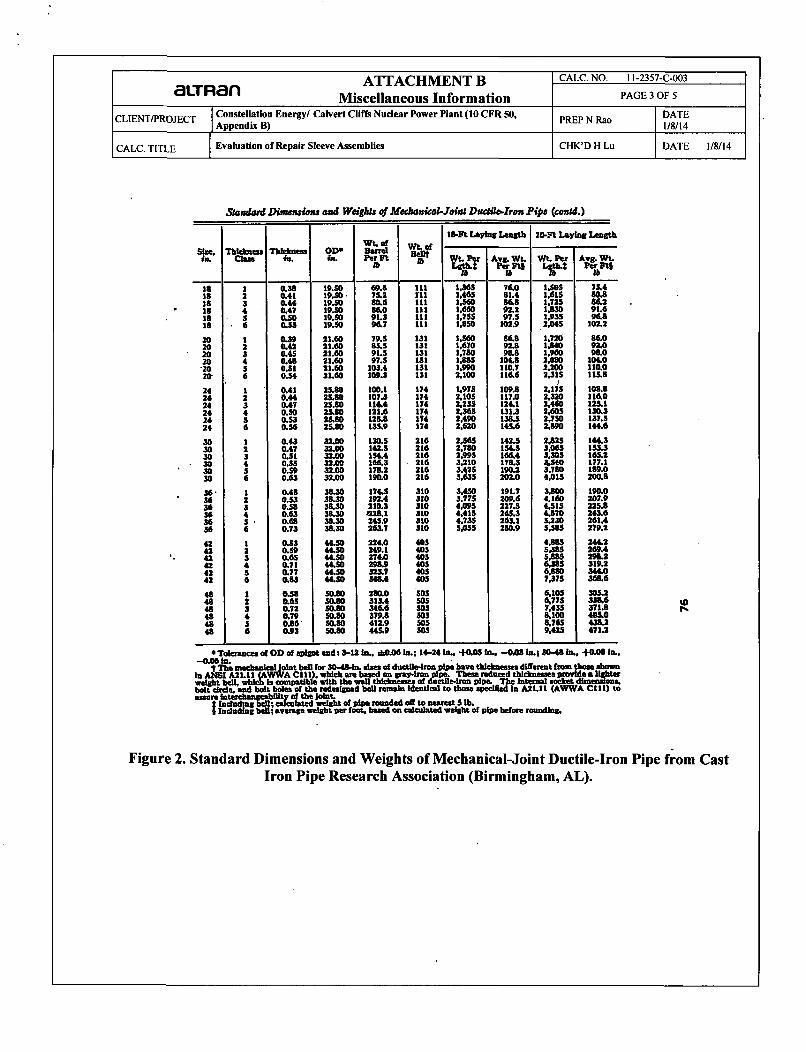
Figure 2. Standard Dimensions and Weights of Mechanical-Joint Ductile-Iron Pipe from CastIron Pipe Research Association (Birmingham, AL).
The•dcged oedeo (l/Dh > 0.015) in a atbkht tube (dcmnnl); Dlpm-Re- wDt•v > 10' 113. 141 4-15
W, o/2f "
54I , ,[
whom -U/Dh), wee the table hela* or sraph a of Diagram 4-12;
we Chapter 2ath = 0.02 fortOw values of t, =t(JIDh F/Fj)soethegraph
Values of~
I FORlDh 1 0.02 0.04 0.06 0.08 0.10 0.15 0.20 0.25 0.30 0.40 O.SO 0.60 0.70 0.80 0.90 3.0
0 1.35 7000 1670 730 400 245 96.0 Sl.S 30.0 18.2 8.25 4.00 2.00 0.97 0.43 0.13 00.2 1.22 6600 1600 687 374 230 94.0 48.0 28.0 17.4 7.70 3.75 1.87 0.91 0.40 0.13 0.01OA 1.10 6310 1630 660 356 221 89.0 46.0 26.S 16.6 7.40 3.60 1.80 0.88 0.39 0.12 0.010.6 0.84 5700 1380 S90 322 199 81.0 42.0 24.0 15.0 6.60 3.20 1.60 0.80 0.36 0.12 0.010.8 0.42 4680 1130 486 264 164 66.0 34.0 19.6 12.2 6.30 2.70 1.34 0.66 0.31 0.11 0.023.0 0.24 4260 1030 443 140 149 60.0 31.0 17.8 11.1 5.00 2.40 1.20 0.61 0.29 0.33 0.02iA 0.10 3930 950 408 221 137 $5.6 28.4 16.4 10.3 4.60 2.25 1.15 0.58 0.28 0.11 0.032.0 0.02 3770 910 391 312 134 53.0 27.4 15.8 9.90 4.40 2.20 1.13 0.58 0.28 0.12 0.043.0 0 3765 913 392 214 132 53.3 27.5 15.9 10.0 4.50 2.24 1.17 0.61 0.31 0.15 0.064.0 0 3775 930 400 216 132 53.8 27.7 16.2 10.0 4.60 2.25 1.20 0.64 0.35 0.16 0.08S.0 0 3850 9386 400 220 133 SS.S 28.5 16.5 10.5 4.75 2.40 1.28 0.69 0.37 0.20 0.106.0 0 3870 940 400 223 133 55.8 28.S 16.6 10.5 4.80 2.42 IJ2 0.70 0.40 0321 0.127.0 0 4000 950 403 230 135 $5.9 29.0 17.0 10.9 5.00 2.60 1.38 0.74 0.43 0.23 0.148.0 0 4000 965 410 336 337 56.0 30.0 17.2 11.2 5.10 1.58 1.45 0.78 0.45 0.26 0.169.0 0 4080 983 430 240.440 $7.0 30.0 17.4 11.4 5.30 2.62 1.50 0.80 0.50 0.28 0.18
10 0 4110 1000 430 245 146 59.7 31.0 M8.2 13.5 SAO 2.80 1.57 0.89 0.63 0.32 0.20
Figure 3. Coefficient of Fluid Resistance (pressure loss coefficient) in Thick-edged Orifice in aStraight Tube, Reference 11.
Thicko.ded orifice UIDh > 0.015) Installed In a transtionsecton; Re = wDv > 10' 113,14]
DIa8rm4-12
D1, = 4FOno
(• ,)+I I i, F
? t1 whernve- lDh);\P2/DA Dh for h mee Chapter 2
I1 0 0.2 0.4 0.6 0.8Dh
v 1.35 1.22 1.10 0.84 0642! 1.0 1.2 1.6 2.0 2.4
7 0.24 0.16 0.07 0.02 "0
Figure 4. Coefficient of Fluid Resistance (pressure loss coefficient) in Thick-edged OrificeInstalled in a Transition Section, Reference 11.

ATTACHMENT B CALC. NO. 11-2357-C-003
aLTRa' Miscellaneous Information PAGE 5 OF 5
CLIENT/PROJECT Constellation Energy/ Calvert Cliffs Nuclear Power Plant (10 CFR 50, PREP N Rao DATEAppendix B) 1/8/14
CALC. TITLE Evaluation of Repair Sleeve Assemblies CHK'D H Lu DATE 1/8/14
ccril-F
2..I -
" .. . .10% C I1L i ", I
USEFUL INIrOIIMATIONWEIGHTS OF 1tI01l II.I• IIMIEN 1IPE1 AND(;ONVIAIHVI II WA I V.|14
Pipe Wolgltl.llh/I. Il'1tih-on joint)Size4In. PMit IWI,)4 Water (Ww)#3 10 . 34 3 66 :1 12a 30) 22
10 311 3412 491 4914 67fi616 8818 11020 JlI' I 3624 ,,19 39630 I l¶1 30736 1lit 1 42242 .. 60148 ~ i 785
'Based on Class 2 push , Idmfl dtlzlhlo Iron pipe In 20 ft.lengths.IBased on nominal pllm MlP1m,
USEFUl. INOI'IMA'fION
LINEAR EXPANSION OF OUTILE IRON PIPE
The coefficient el Itnuar 4upamilnn ol ductile Iron maybe taken as 0.0000(X62 pil, s(h'roo Fahrenheit. The ex-pansion or contracltio In hgichoi Ilml will take place In aline of fgven length with vartgn Iomiprdlure changes Is'lshown In the followlng Inlilo:
Temp. LENGTH OF LINE IN FEETDifference -
IF 100 500 1000 9260
5 0.037 0. 19 0.37 1.9610 0.014 03:7 0.74 3.9320 0.149 -A.74 0.15 7.8630 0.223 1.12 2.23 11.7840 0.298 1.49 2.98 15.7150 0.372 1.116- 3.72 19.6460 0,446 2.23 4.46 23.5770 0.520 P.60 5.20 27.5080 0.595 2.98 5.95 314A390 0.670 3l.36 6.70 35.35
100 0.744 :1.72 7.44 39.28120 0.893 4.46 8.93 47.14150 1.116 5.5• 11.16 58.92
L{~A4
K-
IKcýI a4..' -I
2&-L1.A 72
iii-I-
Figure 5. Excerpt from CIPRA, Guide to Installation of Ductile Iron Pipe, Cast Iron PipeResearch Association, Oakbrook, IL, 1972, (Reference 19).

ATTACHMENT C CALC. NO. 11-2357-C-003
aLTRFlan Email Correspondence PAGE I OF 3
CLIENT/PROJECT Constellation Energy/ Calvert Cliffs Nuclear Power Plant (10 CFR 50, PREP N Rao DATEAppendix B) 1/8/14
CALC. TITLE Evaluation of Repair Sleeve Assemblies CHK'D H Lu DATE 1/8/14
ATTACHMENT C
Email Correspondence
ATTACHMENT C CALC. NO. 11-2357-C-003
aLTRan Email Correspondence PAGE 2 OF 3
CLIENT/PROJECT Constellation Energy/ Calvert Cliffs Nuclear Power Plant (10 CFR 50, PREP N Rao DATEAppendix B) 1/8/14
CALC. TITLE Evaluation of Repair Sleeve Assemblies CHK'D H Lu DATE 1/8/14
From: Mike Fox Fmailto:mike.fox(hydratechllc.com]Sent: Wednesday, November 30, 2011 4:35 PMTo: Hammelmann RobertSubject: RE: Hydraulic loading during installation
Robert,
The recommended expander pressure is 3500 psi (for both sizes)
The cylinder bore size is 1.69" (typical expander). We do have a smaller expander with 1.00" cylinder
Based on the 1.69" cylinder and 3500 psi, the imposed pressure on pipe is estimated as follows:
Contact pressure on L.D of pipe for 30.4" = 260 psiContact pressure on L.D of pipe for 36.54" = 215 psi
Compression force on retaining band = 7850 psi
Michael FoxHydraTech Engineered ProductsOffice: 513.827.9169Mobile: 513.404.9701
[T 'ATTACHMENT C CALC. NO. 11-2357-C-003
Email Correspondence PAGE 3 OF 3
CLIENT/PROJECT Constellation Energy/ Calvert Cliffs Nuclear Power Plant (10 CFR 50,Appendix Bo)e
CALC. TITLE IEvaluation of Repair Sleeve Assemblies
PREP N Rao DATE1/8/14
CHK'D H Lu DATE 1/8/14
Chock Alfred
From:Sent:To:CcSubject:Attachments:
Categories:
Hussain, Emran M <[email protected]>Tuesday, February 21, 2012 3:53 PM
Hammelmann RobertDrake, Andre SFW: Important message from Constellation Energy
Document.pdf
Blue Category
Bob,1. For pressure, use Document 92769, rev. 49 2. Flow Rate use UFSAR rev. 43; Pump flow rate 2 x 20,000 gpm = 40,000
gpm which is slightly higher than your number.
Emran
---- Original Message~--From: PRT4293 Imallto:[email protected]]Sent: Tuesday. February 21, 2012 3:50 PM
To: Hussain, Emran MSubject: Important message from Constellation Energy
Please open the attached document. This document was digitally sent to you using an HP Digital Sending device.
>>> This e-mail and any attachments are confidential, may contain legal, professional or other privileged information,
and are intended solely for the addressee. If you are not the intended recipient, do not use the information In this e-
mail in any way, delete this e-mail and notify the sender. CEG-IP1

aLTRanATTACHMENT D
Miscellaneous Calvert Cliff D
CALC. NO. 11-2357-C-003
PAGE I OF 2
CLIENT/PROJECT Constellation Energy/ Calvert Cliffs Nuclear Power Plant (10 CFR 50,C Appendix B)
CALC. TITLE Evaluation of Repair Sleeve Assemblies
ATTACHMENT D
Miscellaneous Calvert Cliff Documents

aaRcan ATTACHMENT D CALC. NO. 11-2357-C-003c Miscellaneous Calvert Cliff Documents PAGE 2 OF 2
Constellation Energy/ Calvert Cliffs Nuclear Power Plant (10 CFR 50, PREP N Rao DATECLIENT/PROJECT Appendix B) 1/8/14
CALC. TITLE Evaluation of Repair Sleeve Assemblies CHK'D H Lu DATE 1/8/14
63GE D:*euinsnt 92769 Page 47 o87 ]isio. 49
Figure 5. Calvert Cliffs M-601 Piping Class Summary Sheet No. LC-1 for Salt Water System (underground) Design Rating.