CAHP Master Builder Modeling Guidelines - Microsoft · · 2017-03-07TABLE OF CONTENTS 1 HIGH...
34
Master Builder CAHP Master Builder Modeling Guidelines
-
Upload
trinhthuan -
Category
Documents
-
view
222 -
download
4
Transcript of CAHP Master Builder Modeling Guidelines - Microsoft · · 2017-03-07TABLE OF CONTENTS 1 HIGH...

Master Builder
CAHP Master Builder Modeling Guidelines

Master Builder
TABLE OF CONTENTS 1 HIGH PERFORMANCE ATTICS AND DUCTS IN CONDITIONED SPACE ...............................................................1
1.1 Background .................................................................................................................................................1
1.1.1 2013 Title 24 Requirements ...............................................................................................1
1.2 R-30 in climate zones 2 – 10 and 12 – 16 ...................................................................................................1
1.2.1 2016 Title 24 Requirements and Near-Alternatives...........................................................1
1.3 High Performance Attics (HPA-A and HPA-B) .............................................................................................3
1.3.1 Insulated Roof Tiles (continuous rigid foam exterior alternate) ........................................6
1.3.2 Wedge-It Insulation (rigid foam external alternate) .........................................................6
1.4 Ducts in Conditioned Space ........................................................................................................................7
1.4.1 Ducts in Conditioned Plenum Space (Box or Scissor) .........................................................7
1.4.2 Ducts in Dropped Ceiling ................................................................................................. 11
1.4.3 Ducts within a Cathedral Ceiling (finished attic) ............................................................. 12
1.5 Alternative Designs .................................................................................................................................. 15
1.5.1 Unventilated Attic (UVA) a.k.a. Sealed Attic ................................................................... 15
1.5.2 Ductless Systems (or No-cooling) .................................................................................... 18
2 HIGH PERFORMANCE WALLS ...................................................................................................................... 21
2.1 2013 Title 24 Requirements .................................................................................................................... 21
2.2 2016 Title 24 Requirements .................................................................................................................... 21
2.3 “Above Code” Wall Insulation Options ................................................................................................... 21
2.4 High Performance Wall (HPW) ................................................................................................................ 22
2.5 SIP and ICF Wall Assembly ....................................................................................................................... 24
2.6 Double and Staggered Walls ................................................................................................................... 27

Master Builder
TABLE OF FIGURES Figure 1: Schematic of a high performance attic (HPA) ................................................................... 3
Figure 2. CBECC-Res attic roof construction assembly ..................................................................... 4
Figure 3: CBECC-Res below roof deck insulation (HPA-B) ................................................................ 4
Figure 4. Ceiling (attic roof) insulation value ................................................................................... 5
Figure 5: EnergyPro above deck insulation (HPA-A) ........................................................................ 5
Figure 6: EnergyPro below deck insulation (HPA-B) ......................................................................... 5
Figure 7: CBECC-Res insulated roof tile ............................................................................................ 6
Figure 8: Diagrams of ducts in a conditioned plenum...................................................................... 7
Figure 9: CBECC-Res creating knee walls for plenum space ............................................................. 8
Figure 10: CBECC-Res creating construction assembly for knee wall .............................................. 8
Figure 11: CBECC-Res create a distribution system ......................................................................... 9
Figure 12: CBECC-Res ducts in conditioned space options ............................................................ 10
Figure 13: EnergyPro interior knee wall ......................................................................................... 10
Figure 14: EnergyPro duct location for within conditioned space ................................................. 11
Figure 15: Diagram of ducts in a dropped ceiling ........................................................................... 11
Figure 16: CBECC-Res building tree for a cathedral ceiling– Option 1 separate zone (Left) .......... 13
Figure 17: CBECC-Res building tree for a cathedral ceiling – Option 2 main zone (Right) ............. 13
Figure 18: Diagrams of a UVA ......................................................................................................... 15
Figure 19: CBECC-Res UVA ............................................................................................................. 16
Figure 20: CBECC-Res UVA roof (attic deck) insulation .................................................................. 16
Figure 21: CBECC-Res ceiling (attic floor) insulation with UVA ...................................................... 17
Figure 22: CBECC-Res duct location with UVA ............................................................................... 17
Figure 23: CBECC-Res Cool Vent tab with UVA .............................................................................. 17
Figure 24: EnergyPro ceiling (attic floor) insulation for UVA ......................................................... 18
Figure 25: EnergyPro attic insulation for UVA ................................................................................ 18

Master Builder
Figure 26: EnergyPro duct location for UVA................................................................................... 18
Figure 27: CBECC-Res ductless air distribution system .................................................................. 19
Figure 28: CBECC-Res no-cooling ................................................................................................... 19
Figure 29: EnergyPro ductless air distribution system ................................................................... 20
Figure 30: Wood framed U-factors of insulation assemblies from 2013 Title 24 JA4. ................... 22
Figure 31: CBECC-Res HPW (U-0.051) ............................................................................................ 23
Figure 32. EnergyPro HPW ............................................................................................................. 24
Figure 33. EnergyPro - Import a wall assembly that is not found in the existing list ..................... 24
Figure 34: SIP wall (www.sips.org) and ICF wall (www.buildingscience.org) ................................. 25
Figure 35: CBECC-Res SIP wall ........................................................................................................ 25
Figure 36: CBECC-Res ICF wall ........................................................................................................ 26
Figure 37: EnergyPro’s SIP wall JA4 library ..................................................................................... 26
Figure 38: Staggered wall ............................................................................................................... 27
Figure 39: CBECC-Res double wall (with air gap) ........................................................................... 28
Figure 40: CBECC-Res staggered wall ............................................................................................. 29
Figure 41: EnergyPro double wall (no air gap) ............................................................................... 30
Figure 42: EnergyPro staggered wall .............................................................................................. 30
Figure 41: EnergyPro double wall (no air gap) .................................. Error! Bookmark not defined.
Figure 42: EnergyPro staggered wall ................................................. Error! Bookmark not defined.

CAHP Master Builder Modeling Guidelines Master Builder
1 HIGH PERFORMANCE ATTICS AND DUCTS IN CONDITIONED SPACE A high performance attic (HPA), or cool attic, minimizes temperature difference between the attic space and conditioned air being transported through ductwork in the attic. Locating ducts in conditioned space (DCS) further reduces the potential for unintended conditioned air transfer from ducts to unconditioned spaces.
This guide details the steps for Title 24 modeling of components for High Performance Attics (HPA), Ducts in Conditioned Space (DCS), unvented attics (UVA, also known as sealed attics), and ductless systems. These attic-insulation arrangements are all significant improvements above traditional insulation methods and are all options to comply with the Master Builder program requirements. Best modeling methods may vary with future software releases. This guidebook is based on capabilities and fields in the 2013 CBECC-Res version 4b (812) and EnergyPro version 6.8. Similar modeling is possible for 2016 Code compliance software CBECC-Res 2.0 (857) and EnergyPro 7.0.
1.1 Background
1.1.1 2013 Title 24 Requirements
2013 Mandatory roof assembly and distribution system requirements
• R-30 (U-0.031) ceiling (attic floor) insulation • R-4.2 duct insulation • Duct leakage: <6%
2013 Prescriptive roof assembly and distribution system requirements
• Ceiling (attic floor) insulation: • R-30 in climate zones 2 – 10 and 12 – 16
o R-38 in climate zones 1 and 11 • Radiant Barrier in climate zones 2 – 15 • Duct insulation:
o R-6 in climate zones 1 – 10, 12, and 13 o R-8 in climate zones 11 and 14 – 16
• Cool Roof (aged solar reflectance/thermal emittance) o 0.20/0.75 in climate zones 10-15 o NR in climate zones 1-9, and 16
• Whole House Fan in climate zones 8 – 14 • 6% duct leakage
1.1.2 2016 Title 24 Requirements and Near-Alternatives
2016 Mandatory roof assembly and distribution system requirements
• Ceiling (attic floor) insulation: R-22 (U-0.043)

CAHP Master Builder Modeling Guidelines Master Builder
2016 Prescriptive roof assembly and distribution systems. Applicable in climate Zones 4, & 8-16. For Climate zones 1-3 and 5-7, prescriptive requirements remain similar to the 2013 Code, using standard attic assemblies. Some nuanced differences apply. Please consult the 2016 Code Standards and Reference Manuals for details. This modeling guide is focused on options for zones 4, & 8-16.
1. High Performance Attics (HPA-A and HPA-B). Construct a standard vented attic with an additional layer of insulation along the roof deck to regulate attic temperature.
o R-38 (U-0.026) ceiling (attic floor) insulation For above deck (HPA-A): R-6 rigid external insulation above the roof deck (R-8 if
shingle roofing) For below deck (HPA-B): R-13 below deck between rafters (R-18 if shingle
roofing) o Radiant barrier (for HPA-A only) o R-8 duct insulation o Cool Roof (same as 2013 Prescriptive) o Whole House Fan in climate zones 8 – 14 o 5% duct leakage
2. Ducts in Conditioned Space (DCS). Place all duct and air handler equipment within the thermal envelope of intentionally conditioned space. This can be achieved with a combination of drop soffits, plenums, interstitial space between floors, and mechanical chase ways.
o Duct and air handler location confirmed by field verification and diagnostic testing o Ceiling (attic floor) insulation:
R-30 in climate zones 2 – 10 and 12 – 16 R-38 in climate zones 1 and 11
o 5% duct leakage o R-6 duct insulation
Alternate roof assembly and distribution systems permitted in Master Builder
1. Ducts located in an unventilated attic (UVA), also known as a sealed attic. Move the thermal and air barriers from the ceiling to the attic roof, eliminating attic ventilation. The attic space isn’t fully finished or intentionally conditioned. The ducts and air handling equipment is in the unventilated attic space. This option typically models with slightly worse results than the code prescriptive requirements detailed above. This option is not the same as ducts in conditioned space, and ducts in conditioned space modeling credit cannot be taken with this assembly.
o R-22 (mandatory minimum) insulation at the roof deck (NOT at ceiling/attic floor) o Gable walls insulated as-per wall insulation standards o No attic floor insulation, and minimal air-sealing between the attic and the conditioned
living space. 2. Ductless (heat pump, mini-splits, or no-cooling system). Ductless heating and cooling systems,
such as mini-splits and through the wall packaged units offer an alternative to high performance attics and ducts in conditioned space. Master Builder can accept no-cooling with exceptional envelope design.

CAHP Master Builder Modeling Guidelines Master Builder
1.2 High Performance Attics (HPA-A and HPA-B)
Figure 1: Schematic of a high performance attic (HPA)
Source: Adapted from http://www.ductsinside.org/
A high performance attic (HPA) implements measures that minimize temperature difference between the attic space and the conditioned air being transported through ductwork in the attic. This design assumes that the duct and equipment are located in the attic, as is typical in current California residential construction.
CBECC-Res
The ceiling (attic floor) insulation is not modeled at the attic building level; it is modeled as part of the conditioned zone as the ceiling below attic (Residential Compliance Manual for the 2013 Energy Efficiency Standards, section 6.6.1). To model insulation that is adjacent to the roof deck, either above or below, a user must specify the insulation in the roof construction assembly.
1. Under Envelope tab, create or edit Construction Assemblies for Asphalt, Tile, or another Roof type with the “Can be Assigned To” Attic Roofs
2. HPA-A: Select above deck insulation level (R-6, or R-8 with shingle roofing). Alternatively, a higher than prescriptive value may be assigned
3. HPA-B: Select Cavity / Frame insulation level (R-13, or R-18 with shingle roofing). Alternatively, a higher than prescriptive value may be assigned.
o This modeling assumes the assigned framing element exists throughout the depth of the installed insulation. If insulation will go beyond the framed cavity, and become continuous as it extends past the studs (in the case of boxed netting or spray foam for instance), the assigned Cavity/Frame insulation level may require custom calculations to account for and take credit for this layer of continuous insulation.
4. Assign this Construction Assembly to the Attic’s Construction dropdown selection.
CAHP Master Builder Modeling Guidelines Master Builder
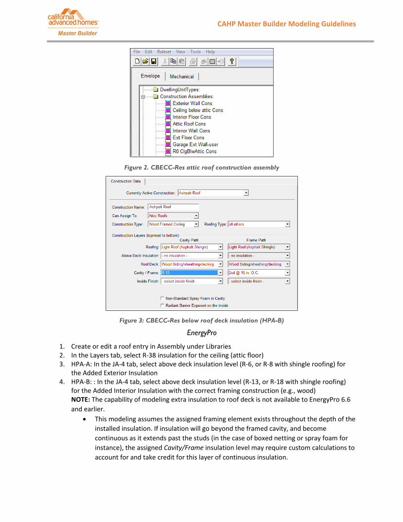
Figure 2. CBECC-Res attic roof construction assembly
Figure 3: CBECC-Res below roof deck insulation (HPA-B)
EnergyPro
1. Create or edit a roof entry in Assembly under Libraries 2. In the Layers tab, select R-38 insulation for the ceiling (attic floor) 3. HPA-A: In the JA-4 tab, select above deck insulation level (R-6, or R-8 with shingle roofing) for
the Added Exterior Insulation 4. HPA-B: : In the JA-4 tab, select above deck insulation level (R-13, or R-18 with shingle roofing)
for the Added Interior Insulation with the correct framing construction (e.g., wood) NOTE: The capability of modeling extra insulation to roof deck is not available to EnergyPro 6.6 and earlier.
• This modeling assumes the assigned framing element exists throughout the depth of the installed insulation. If insulation will go beyond the framed cavity, and become continuous as it extends past the studs (in the case of boxed netting or spray foam for instance), the assigned Cavity/Frame insulation level may require custom calculations to account for and take credit for this layer of continuous insulation.

CAHP Master Builder Modeling Guidelines Master Builder
Figure 4. Ceiling (attic roof) insulation value
Figure 5: EnergyPro above deck insulation (HPA-A)
Figure 6: EnergyPro below deck insulation (HPA-B)

CAHP Master Builder Modeling Guidelines Master Builder
1.2.1 Insulated Roof Tiles (continuous rigid foam exterior alternate)
These roof tiles are specifically manufactured to contain insulation to increase the thermal performance of the roofing material. These tiles function similar to continuous insulation above the roof deck.
CBECC-Res
CBECC-Res 2013 4 adds an insulated roof tile system into the Construction library (i.e. Roofing types). It provides the ability of modeling an insulated roof tile system.
1. Under Envelope tab, create or edit a Construction Assembly that “Can Assign to” the Attic Roof. 2. Select “steep slope roof tile, metal tile, or wood shakes” as Roof Type. 3. Under “Roofing” dropdown selection, three available options for insulated roof tile systems are
Green Hybrid Roofing Tile, GHR Tile with ENSOPRO, and GHR Tile with ENSOPRO Plus (detailed material characteristics can be found in Table 5: Materials List, 2016 Residential ACM Reference Manual).
Figure 7: CBECC-Res insulated roof tile
EnergyPro
As of August 2016, EnergyPro does not have the ability to model insulated roof tiles. This capability may be available in future software releases.
1.2.2 Wedge-It Insulation (rigid foam external alternate)
Wedge-It insulation are wedge-shaped extruded polystyrene blocks that are installed between battens underneath the concrete tiles. Although Wedge-It blocks are not continuous, this insulation option can comply with Master Builder requirements, and can meet Title 24 prescriptive requirements.
CBECC-Res and EnergyPro
1. Assign a weighted area average R-value as a continuous exterior insulation layer on the roof deck to represent the Wedge-It insulation.
The weighted area average R-value must consider the air-gaps between Wedge-It blocks (for water drainage), the gaps for battens, and the tapered-wedge geometry of the Wedge-It cross section itself.
CAHP Master Builder Modeling Guidelines Master Builder
1.3 Ducts in Conditioned Space
Ducts in conditioned space credit can only be taken if all ducts, and air handling equipment is entirely contained within finished, habitable, and directly conditioned spaces. Credit can be taken with or without HERS verification. HERS verification credit will lead to higher compliance. Qualifying designs include ducts in a conditioned plenum space, ducts in a dropped ceiling within the conditioned space, ducts in interstitial spaces between floors, and ducts under a finished cathedral ceiling. When ducts are located in an unventilated attic (sealed attics), they are not considered to be in in conditioned space and credit should not be taken. For sealed attics, see section 1.4.1 Unventilated Attic (UVA) a.k.a. Sealed Attic
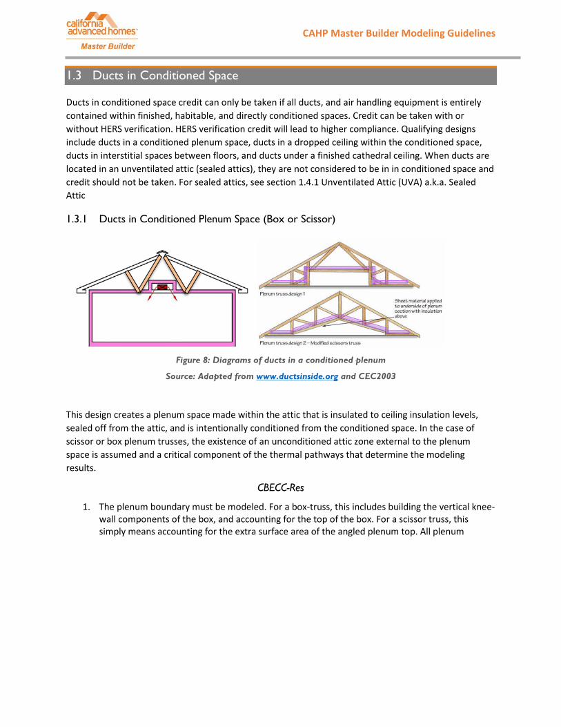
1.3.1 Ducts in Conditioned Plenum Space (Box or Scissor)
Figure 8: Diagrams of ducts in a conditioned plenum
Source: Adapted from www.ductsinside.org and CEC2003
This design creates a plenum space made within the attic that is insulated to ceiling insulation levels, sealed off from the attic, and is intentionally conditioned from the conditioned space. In the case of scissor or box plenum trusses, the existence of an unconditioned attic zone external to the plenum space is assumed and a critical component of the thermal pathways that determine the modeling results.
CBECC-Res
1. The plenum boundary must be modeled. For a box-truss, this includes building the vertical knee-wall components of the box, and accounting for the top of the box. For a scissor truss, this simply means accounting for the extra surface area of the angled plenum top. All plenum
CAHP Master Builder Modeling Guidelines Master Builder
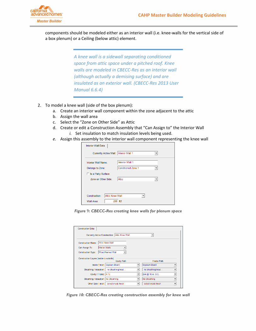
components should be modeled either as an interior wall (i.e. knee-walls for the vertical side of a box plenum) or a Ceiling (below attic) element.
2. To model a knee wall (side of the box plenum): a. Create an interior wall component within the zone adjacent to the attic b. Assign the wall area c. Select the “Zone on Other Side” as Attic d. Create or edit a Construction Assembly that “Can Assign to” the Interior Wall
i. Set insulation to match insulation levels being used. e. Assign this assembly to the interior wall component representing the knee wall
Figure 9: CBECC-Res creating knee walls for plenum space
Figure 10: CBECC-Res creating construction assembly for knee wall
A knee wall is a sidewall separating conditioned space from attic space under a pitched roof. Knee walls are modeled in CBECC-Res as an interior wall (although actually a demising surface) and are insulated as an exterior wall. (CBECC-Res 2013 User Manual 6.6.4)

CAHP Master Builder Modeling Guidelines Master Builder
NOTE: When creating the Ceiling (below attic) for a box plenum, ceiling area will remain the same to account for the insulation on top of the plenum space. If the insulation on top of the box-plenum matches the insulation used elsewhere in the attic. No separate modeling is required. If it differs, model this area similar to modeling an FAU platform used; build a new Ceiling below attic component and assign the surface area and a construction assembly representing the R-value of the top of the plenum.
If modeling a scissor truss, model a Ceiling below attic component. The surface area should account for the extra surface that is the result of an angled attic floor.
Distribution System modeling
1. Under Mechanical Tab, create or edit a Distribution System to place ducts in one of the following, depending on plan:
a. Duct located within conditioned space (except < 12 lineal feet) b. Ducts located entirely in conditioned space c. Verified low-leakage ducts entirely in conditioned space (NOTE: Requires HERS
Verification) NOTE: For option a., the 12 linear feet limit includes the air-handler length itself. For options b. and c., the air-handler must also be located in conditioned space. For all three options, the modeling algorithms eliminates conduction losses from internally located ducts, but will only eliminate losses due to air-leakage if the user selects the verified low leakage ducts in conditioned space credit, which requires HERS verification.
Figure 11: CBECC-Res create a distribution system

CAHP Master Builder Modeling Guidelines Master Builder
Figure 12: CBECC-Res ducts in conditioned space options
EnergyPro
1. Create one interior wall (knee wall) in the Conditioned Zone that is adjacent to the attic a. The interior wall should have the square footage of all vertical plenum surfaces
combined. For example, if a plenum has two 50 sf. Surfaces, and two 25 sf. surfaces, the interior wall would have a total of 150 sf.
2. Input the appropriate information for the wall (for example, wall area and floor elevation) 3. Check the Next to Residential Attic checkbox 4. Click on the New Assembly field 5. Select or create a wall assembly with the insulation R-value being used on the plenum
Distribution systems
1. Create or edit an existing HVAC system 2. Click on the distribution tab at the top of the HVAC system page, and then select “Conditioned”
in the Duct Location dropdown menu 3. If the low-leakage ducts test will be verified by a HERS Rater, select the option of ‘Ducts in
Conditioned Space with Leakage Verified’ (NOTE: Requires HERS Verification)
Figure 13: EnergyPro interior knee wall

CAHP Master Builder Modeling Guidelines Master Builder
Figure 14: EnergyPro duct location for within conditioned space
1.3.2 Ducts in Dropped Ceiling
Figure 15: Diagram of ducts in a dropped ceiling
Source: www.ductsinside.org
A dropped ceiling is a space made within the building envelope under the insulated ceiling (attic floor) that is sealed from the attic and uses the Ceiling (below attic) insulation.
CBECC-Res
The only modeling action is to place the ducts and equipment in conditioned space. The thermal envelop will be at the ceiling (attic floor) and no additional insulation or modeling requirements are necessary.
NOTE: CBECC-Res will assume that HVAC equipment is also located in conditioned space. This option eliminates conduction losses, but will only eliminate losses due to leakage if the user selects verified low leakage ducts in conditioned space, which requires HERS verification.
1. Under the Mechanical tab, create or edit the Distribution Systems for a ducts located in conditioned space scenario.
• Choose one of the three options: o Ducts located Ducts located within conditioned space (except <12 ft) o Ducts located entirely in conditioned space o Verified low-leakage ducts entirely in conditioned space. NOTE: Requires HERS
verification.

CAHP Master Builder Modeling Guidelines Master Builder
Energy Pro
1. Create or edit an existing HVAC system 2. Select the distribution tab at the top of the HVAC system window 3. Select “Conditioned” in the Duct Location dropdown menu 4. If the low-leakage ducts test will be verified by a HERS Rater, select the option of ‘Ducts in
Conditioned Space with Leakage Verified’ (NOTE: Requires HERS Verification)
1.3.3 Ducts within a Cathedral Ceiling (finished attic)
A cathedral ceiling is a roof that is finished on the interior and meant to be used as a habitable space. A cathedral ceiling (finished attic) is not considered an unventilated attic (UVA); the difference is that the space below the roof deck of a cathedral ceiling is fully finished, habitable and intentionally conditioned. This design may add additional conditioned square footage to the home if it creates a loft-type space. The temperature in the space below the roof fluctuates with the rest of the conditioned space, whereas the temperature in an unventilated attic may fluctuate separately from the conditioned space.
CBECC-Res
1. Create a cathedral ceiling: • Delete both the Ceiling (below attic) and the Attic (if they are currently present in
model) • Create a Cathedral Ceiling for the conditioned zone. • Edit or create a Construction Assembly for insulation that “Can Assign to” the Cathedral
Ceiling (minimum R-22 insulation). i. NOTE: an Inside Finish, such as gypsum board, must be used for a habitable
space. 2. Creating conditioned space below the cathedral ceiling (e.g. a loft):
• Option 1: If the cathedral ceiling will be in a separate conditioned zone (e.g. a loft), create a separate conditioned zone (similar to creating a second story zone)
i. Omit the Ceiling (below attic) ii. Add any necessary floor over garage
3. Under the Mechanical tab, create or edit the Distribution Systems for a ducts located in conditioned space scenario.
• Choose one of the three options: o Ducts located Ducts located within conditioned space (except <12 ft) o Ducts located entirely in conditioned space o Verified low-leakage ducts entirely in conditioned space. NOTE: Requires HERS
verification.

CAHP Master Builder Modeling Guidelines Master Builder
Figure 16: CBECC-Res building tree for a cathedral ceiling– Option 1 separate zone (Left)
Figure 17: CBECC-Res building tree for a cathedral ceiling – Option 2 main zone (Right)
EnergyPro
If the cathedral ceiling will be over the conditioned floor area of the house and does not create a separate zone (e.g. a loft):
1. Delete or edit existing roof space in the zone (if necessary) • If the cathedral ceiling will only cover part of the conditioned zone, then edit the
existing roof to only reflect the portion of the roof that is not a cathedral ceiling. 2. Create a cathedral ceiling for the conditioned zone(s) that it will cover
• Click on the New Assembly field and select a cathedral ceiling from the roof library or import a cathedral ceiling with the appropriate insulation R-value from the JA4 Library.
If the cathedral ceiling will be over conditioned space that is part of a separate zone (e.g. loft):
1. Delete or edit existing roof space in the zone (if necessary) • If the cathedral ceiling will only cover part of the conditioned area, then edit the existing
roof to reflect only the portion of the roof that is not a cathedral ceiling. 2. Create a new conditioned zone in the building tree 3. Create a new room/floor in the conditioned zone
• In the General tab, enter the square footage and average ceiling height of the cathedral ceiling
4. Create a cathedral ceiling for the new room • Add a roof (cathedral ceiling) to the new room/floor
i. The roof area should equal the floor area of the sealed attic space • Click on the New Assembly field and select a cathedral ceiling from the roof library or
import a cathedral ceiling with the appropriate R-value from the JA4 Library. EnergyPro uses the term ‘Rafter’ ceiling in the JA4 library to represent cathedral ceiling assemblies.

CAHP Master Builder Modeling Guidelines Master Builder
Figure 18: Creating a Rafter/Cathedral assembly from the JA4 Library
5. Add an Interior Floor to the room (e.g. loft) (this represents the floor between the new room (e.g. loft)and the floor below)
• If the floor of the new room (e.g. loft) is only over conditioned space i. Add an internal floor beneath the room
ii. Enter the appropriate area (should be the floor area of the sealed attic) iii. Click on the New Assembly field and enter the appropriate R-Value and details
for the interior surface iv. In the Adjacent To field, select the appropriate room
• If the floor of the new room (e.g. loft) is over both conditioned and unconditioned space (i.e. over living space and garage space)
i. Create two separate floor surfaces; one for the area over conditioned space (interior floor), and one for the area over unconditioned space (exposed floor).
ii. Enter the appropriate area for each interior surface (both surfaces should have a total area equal to that of the sealed attic floor area)
iii. Click on the New Assembly field for each interior surface, and enter the appropriate R-Values and details for each interior surface
iv. In the Adjacent To field, select the appropriate room for the interior surface over conditioned space. Then select the appropriate unconditioned space (ex. “garage”) in the Adjacent To field for the interior surface over unconditioned space.
CAHP Master Builder Modeling Guidelines Master Builder
1.4 Alternative Designs
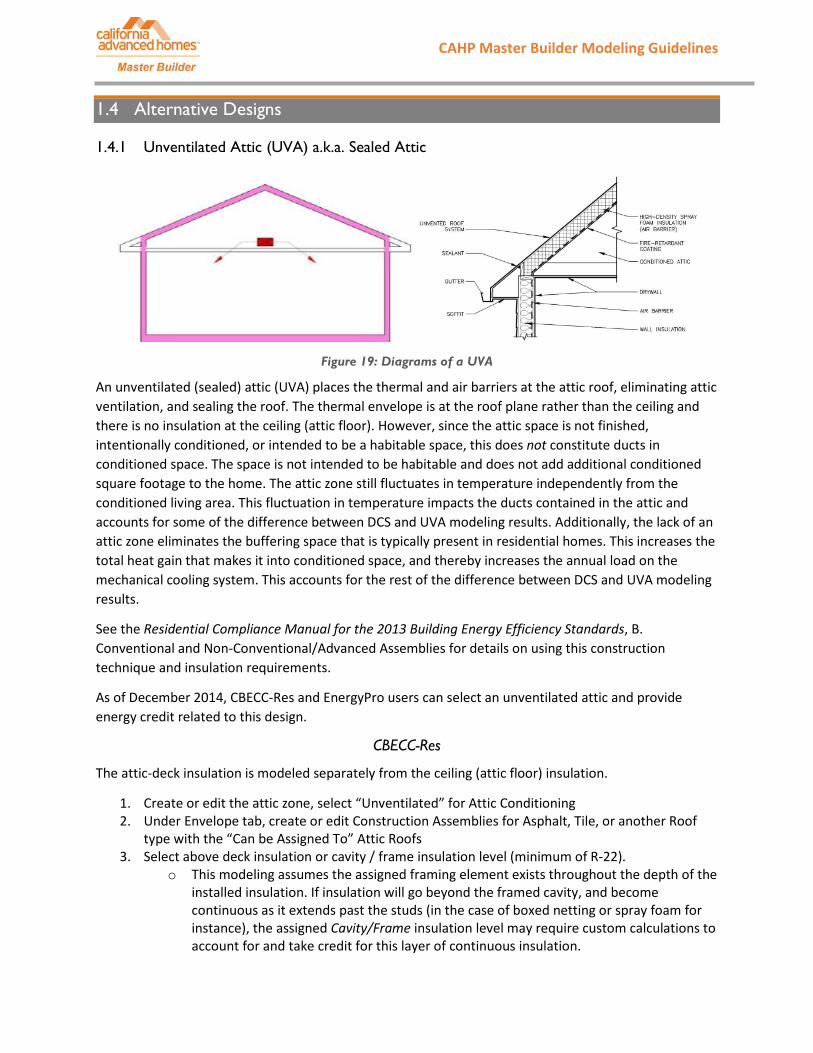
1.4.1 Unventilated Attic (UVA) a.k.a. Sealed Attic
Figure 19: Diagrams of a UVA
An unventilated (sealed) attic (UVA) places the thermal and air barriers at the attic roof, eliminating attic ventilation, and sealing the roof. The thermal envelope is at the roof plane rather than the ceiling and there is no insulation at the ceiling (attic floor). However, since the attic space is not finished, intentionally conditioned, or intended to be a habitable space, this does not constitute ducts in conditioned space. The space is not intended to be habitable and does not add additional conditioned square footage to the home. The attic zone still fluctuates in temperature independently from the conditioned living area. This fluctuation in temperature impacts the ducts contained in the attic and accounts for some of the difference between DCS and UVA modeling results. Additionally, the lack of an attic zone eliminates the buffering space that is typically present in residential homes. This increases the total heat gain that makes it into conditioned space, and thereby increases the annual load on the mechanical cooling system. This accounts for the rest of the difference between DCS and UVA modeling results.
See the Residential Compliance Manual for the 2013 Building Energy Efficiency Standards, B. Conventional and Non-Conventional/Advanced Assemblies for details on using this construction technique and insulation requirements.
As of December 2014, CBECC-Res and EnergyPro users can select an unventilated attic and provide energy credit related to this design.
CBECC-Res
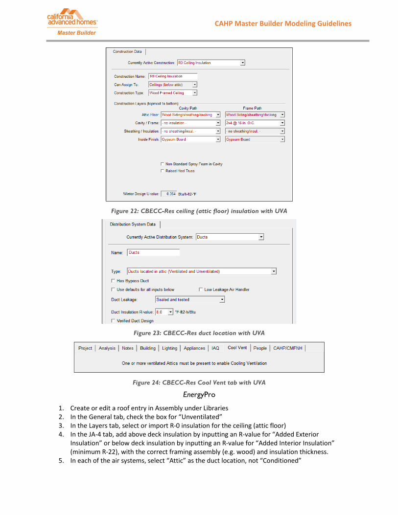
The attic-deck insulation is modeled separately from the ceiling (attic floor) insulation.
1. Create or edit the attic zone, select “Unventilated” for Attic Conditioning 2. Under Envelope tab, create or edit Construction Assemblies for Asphalt, Tile, or another Roof
type with the “Can be Assigned To” Attic Roofs 3. Select above deck insulation or cavity / frame insulation level (minimum of R-22).
o This modeling assumes the assigned framing element exists throughout the depth of the installed insulation. If insulation will go beyond the framed cavity, and become continuous as it extends past the studs (in the case of boxed netting or spray foam for instance), the assigned Cavity/Frame insulation level may require custom calculations to account for and take credit for this layer of continuous insulation.

CAHP Master Builder Modeling Guidelines Master Builder
o No Radiant Barrier suggested or required when using below deck insulation o No inside finish necessary for a non-habitable space
4. Assign this Construction Assembly to the Attic’s Construction dropdown selection. 5. Edit or create a Construction Assembly that is R0 (no insulation) for the Ceiling Insulation that
“Can be Assigned To” Ceiling (below attic). 6. Apply this Construction Assembly to the Ceiling (below attic) in the Conditioned Zone 7. Under the Mechanical Tab, place Air Distribution System in attic (Ventilated and Unventilated),
not in conditioned space. NOTE: Once the project has a sealed attic, the home will no longer be eligible for a Whole House Fan due to the technical feasibility of that construction. When viewing the project overview the Cool Vent tab will display this information. This may lead to significant impacts on energy budgets for some climate zones. The CEC is evaluating the feasibility and need to create an option for a whole house fan, ducted to outside and in a sealed attic.
Figure 20: CBECC-Res UVA
Figure 21: CBECC-Res UVA roof (attic deck) insulation
CAHP Master Builder Modeling Guidelines Master Builder
Figure 22: CBECC-Res ceiling (attic floor) insulation with UVA
Figure 23: CBECC-Res duct location with UVA
Figure 24: CBECC-Res Cool Vent tab with UVA
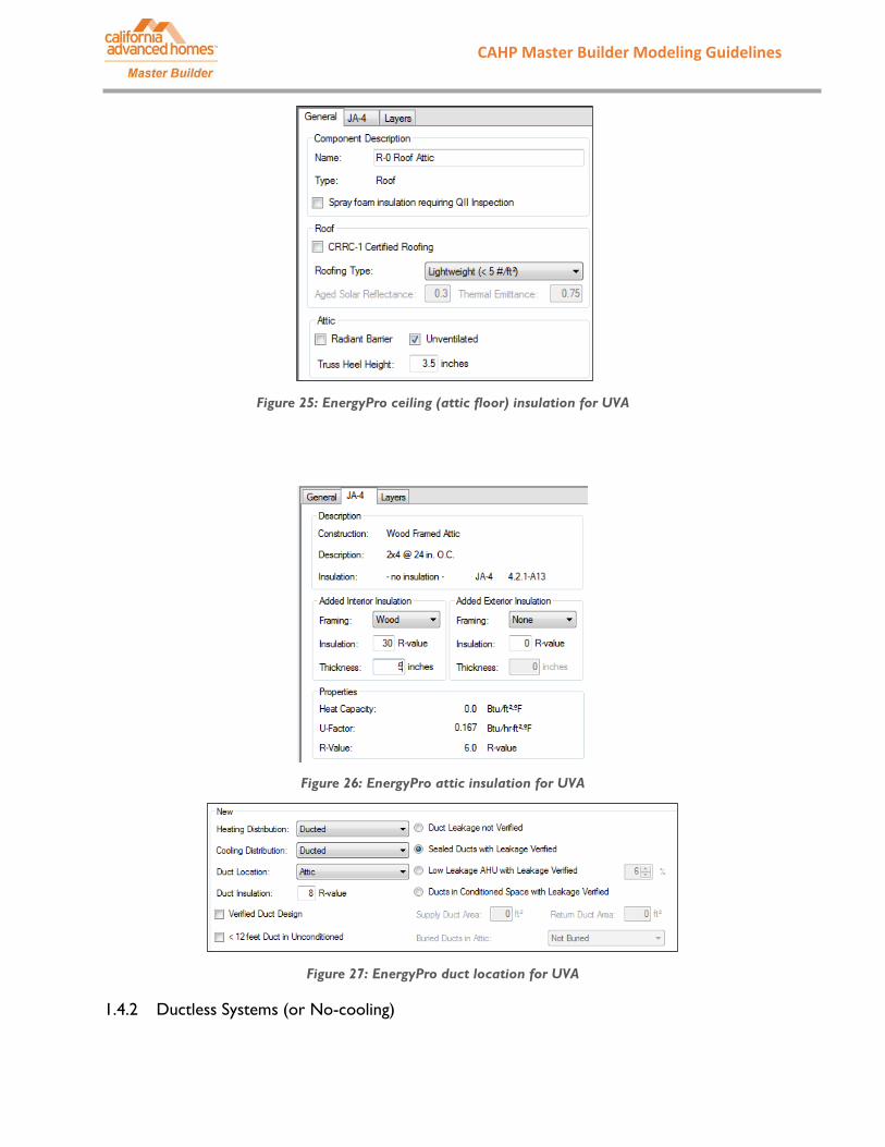
EnergyPro
1. Create or edit a roof entry in Assembly under Libraries 2. In the General tab, check the box for “Unventilated” 3. In the Layers tab, select or import R-0 insulation for the ceiling (attic floor) 4. In the JA-4 tab, add above deck insulation by inputting an R-value for “Added Exterior
Insulation” or below deck insulation by inputting an R-value for “Added Interior Insulation” (minimum R-22), with the correct framing assembly (e.g. wood) and insulation thickness.
5. In each of the air systems, select “Attic” as the duct location, not “Conditioned”
CAHP Master Builder Modeling Guidelines Master Builder
Figure 25: EnergyPro ceiling (attic floor) insulation for UVA
Figure 26: EnergyPro attic insulation for UVA
Figure 27: EnergyPro duct location for UVA
1.4.2 Ductless Systems (or No-cooling)

CAHP Master Builder Modeling Guidelines Master Builder
Air distribution systems without ducts such as heat pumps, mini-splits, wall furnaces, window AC units, floor furnaces, or others are considered ductless and have no duct leakage or duct loss. However, CEC has not verified the performance of these systems and therefore, no credit is awarded in the simulation software. Master Builder will accept ductless systems, as well as no-cooling with an exceptional envelope to ensure occupant comfort.
NOTE: Mini-split, multi-split, evaporative cooling, room air conditions, room heat pumps and ground source heat pumps—until an exceptional method is approved, these systems are modeled as equivalent to a standard design system with no penalty and no credit (CBECC-Res User Manual).
NOTE: If No-cooling is designed in the proposed building, the simulation software will install a minimally efficient system equivalent to a standard design system with no penalty and no credit.
CBECC-Res
Ductless system
1. Under the Mechanical Tab, place Air Distribution System in attic (Ventilated and Unventilated), not in conditioned space.
Figure 28: CBECC-Res ductless air distribution system
No cooling system
1. Under the Mechanical Tab, in the HVAC System tree, create a Cooling component 2. Select “NoCooling – No cooling equipment” from the drop down menu
Figure 29: CBECC-Res no-cooling

CAHP Master Builder Modeling Guidelines Master Builder
EnergyPro
Ductless system
1. Under the Distribution tab within the HVAC system, select one of the Ductless options. • Options include ductless with a fan or ductless without a fan, this will depend on the
selected system.
Figure 30: EnergyPro ductless air distribution system
No cooling system
2. In the Cooling tab of the HVAC system, set the output and sensible output fields to zero so the cooling system is undefined.

CAHP Master Builder Modeling Guidelines Master Builder
2 HIGH PERFORMANCE WALLS This guide details the steps to model high performance walls (HPW) in CBECC-Res and EnergyPro software. This guidebook is based off of 2013 CBECC-Res version 3 and EnergyPro version 6.
2.1 2013 Title 24 Requirements
2013 Mandatory Wall Insulation Requirements
• U-0.102 (R-13) in 2x4 framing • U-0.074 (R-19) in 2x6 framing
2013 Prescriptive Wall Insulation Requirements
• U-0.065 (R-15+4 or R-13+5 in 2x4 framing, or R-19+2 in 2x6 framing)
2.2 2016 Title 24 Requirements
2016 Mandatory wall insulation requirements
• U-0.102 (R-13) in 2x4 framing • U-0.074 (R-19) in 2x6 framing
2016 Prescriptive Wall Insulation Requirements
• U-0.065 (R-15+4 or R-13+5 in 2x4 framing, or R-19+2 in 2x6 framing), in climate zones 6 and 7 • U-0.051 (R-19+5 in 2x6 framing), in climate zones 1-5, and 8-16 (a high performance wall)
2.3 High Performance Wall (U-Factor ≤ 0.51) Insulation Options
To achieve high performance walls, a home builder can employ several strategies. Figure 30 below provides options available to reach a U-factor below 0.051 in standard wood framed walls. Additional options are to install Structural Insulated Panels (SIP) walls, double walls, or other advanced techniques. The U-factor values in CBECC-Res and EnergyPro come from the assemblies in various tables of the 2013 Joint Appendix 5 (JA5), as shown in Figure 30 below for wood framed walls. Common options for high performance walls include:
U-factor Framing Stud Spacing Cavity Insulation Exterior Insulation Cavity Insulation Type 0.050 2x6 24” OC R-19 R-5 (1") Low density fiberglass batt 0.051 2x6 16” OC R-21 R-4 (1") High density batt or BIB 0.049 2x6 16” OC R-19 R-6 (1.25") Low density fiberglass batt 0.051 2x6 16”OC R-19 R-5 (1”) Low density fiberglass batt 0.050 2x4 16” OC R-15 R-8 (2") High density batt

CAHP Master Builder Modeling Guidelines Master Builder
Spacing
Cavity Insulation Nominal Framing Size Rated R-value of Continuous Insulation 2 R-0 R-2 R-4 R-5 R-6 R-7 R-8
A B C D E F G 16 in. OC None Any 1 0.356 0.209 0.146 0.127 0.113 0.101 0.092
R-11 2x4 2 0.110 0.088 0.074 0.068 0.064 0.060 0.056
R-13 2x4 3 0.102 0.082 0.069 0.064 0.060 0.056 0.053
R-15 1 2x4 4 0.095 0.077 0.065 0.060 0.056 0.053 0.050
R-19 2x6 5 0.074 0.063 0.055 0.051 0.049 0.046 0.044
R-211 2x6 6 0.069 0.059 0.051 0.048 0.046 0.043 0.041
R-22 2x6 7 0.072 0.062 0.054 0.051 0.048 0.045 0.043
24 in. OC None Any 12 0.362 0.211 0.148 0.128 0.114 0.102 0.092
R-11 2x4 13 0.106 0.086 0.072 0.067 0.062 0.059 0.055
R-13 2x4 14 0.098 0.079 0.067 0.062 0.058 0.055 0.052
R-15 2x4 22 0.091 0.074 0.063 0.059 0.055 0.052 0.049
R-19 2x6 15 0.071 0.061 0.053 0.050 0.048 0.045 0.043
R-211 2x6 16 0.066 0.057 0.050 0.047 0.045 0.042 0.040
R-22 2x6 17 0.069 0.060 0.052 0.049 0.047 0.044 0.042
Notes 1. Higher density fiberglass batt is required in these cases. 2. Continuous insulation may be installed on either the inside or the exterior of the wall, or both.
Figure 31: Wood framed U-factors of insulation assemblies from 2013 Title 24 JA4.
Alternative wall assembly options
• 2x4 framing with closed-cell spray foam insulation • SIP walls • Insulating Concrete Form (ICF) walls • Double walls • Staggered stud walls
2.4 Standard Assembly High Performance Walls (HPW)
High performance walls (HPW) can be achieved with no major difference from the current traditional wall assemblies. This requires the application of thicker/denser cavity insulation and/or thicker/denser exterior insulation layers. Common construction strategies include 2x6-inch walls at 16-in on center or 24-in on center framing with a combination of cavity and continuous external insulation, for example, a combination of R-19 insulation within 2x6 cavity and R-5 exterior insulation yields a U-factor of 0.051.
CBECC-Res
Model a U-factor of 0.051 with 2x6-inch walls at 16-in on center framing in CBECC-Res.
1. Go to Envelope tab, create or edit Construction Assemblies for Wood Framed Wall with the “Can be Assigned To” Exterior Walls

CAHP Master Builder Modeling Guidelines Master Builder
2. Assign R-19 insulation to Cavity. Additionally, assign R1 Sheathing to interior insulation R4 Synthetic Stucco to Exterior Finish
3. Select the correct framing (i.e. 2x6 @16 in. O.C.) from the Frame dropdown selection 4. Assign this HPW Construction Assembly to the Exterior Wall’s Construction dropdown selection
Figure 32: CBECC-Res HPW (U-0.051)
EnergyPro
Model a U-factor of 0.051 with 2x6-inch walls at 16-in on center framing in EnergyPro.
1. Create an exterior wall in the building tree by right click on ‘Zone’ and select ‘Exterior Wall’ under ‘Add’
2. Click on the New Assembly field for the exterior wall 3. Choose the framing and cavity insulation match your wall assembly (i.e. R19 2x6 @16 in. O.C.)
from the existing library shown at the left side window. If the assembly cannot be found in the left side window list, click the Import tab on the top, and select Wall to import from the EnergyPro built-in JA4 Library.
4. Assign R-5 to exterior insulation

CAHP Master Builder Modeling Guidelines Master Builder
Figure 33. EnergyPro HPW
Figure 34. EnergyPro - Import a wall assembly that is not found in the existing list
2.5 SIP and ICF Wall Assembly
A structurally insulated panel (SIP) wall or insulating concrete form (ICF) wall can be used for residential exterior walls. They are typically factory fabricated assemblies; although, it is possible to have a site-built SIP. SIP assemblies typically include an insulation layer with Oriented Strand Board (OSB) sheathing on either side, and ICF assemblies have a concrete core surrounded typically with expanded polystyrene (EPS) or another rigid foam product.

CAHP Master Builder Modeling Guidelines Master Builder
Figure 35: SIP wall (www.sips.org) and ICF wall (www.buildingscience.org)
CBECC-Res
CBECC-Res allows for modeling of SIP and ICF walls.
1. Under Envelope tab, create or edit Construction Assemblies for wall with the “Can be Assigned To” Exterior Walls
2. SIP Wall: selected SIPS Wall for Construction Type, then specify the R-value and depth (in inches) per manufacture specifications.
3. ICF Wall: select Concrete/ICF/Brick for Construction Type, then specify the R-value of each insulation panel for the assembly and the depth of the concrete form per manufacturer specifications.
Figure 36: CBECC-Res SIP wall

CAHP Master Builder Modeling Guidelines Master Builder
Figure 37: CBECC-Res ICF wall
EnergyPro
EnergyPro has SIP and ICF walls in its built-in library for external wall types; however, if the insulation and depth values are not available, a user can create their own SIP or ICF.
1. In the Libraries, create or edit an exterior wall assembly that meets your specifications a. If the SIP or ICF wall is not available in the pre-populated Assembly library, select Import
on the top menu bar, and choose Wall. The JA4 Library window will appear. b. On the left-hand side of the JA4 Library window, select Table 4.3.2, Structurally
Insulated Panel (SIP), OR Table 4.3.13 Insulating Concrete Foam. c. On the right-hand side of the JA4 Library window, select the correct assembly type
based on the wall’s specifications 2. If none of the available wall assemblies in the library match your specifications, select the
closest assembly and add insulation. a. In the JA-4 tab of the selected SIP or ICF assembly, input R-value of insulation into the
Added Interior Insulation section. b. Set the Framing to None because no framing members exist within a SIP or ICF wall.
Figure 38: EnergyPro’s SIP wall JA4 library

CAHP Master Builder Modeling Guidelines Master Builder
2.6 Double and Staggered Walls
Double and staggered walls allow for greater depths of cavity insulation and can also eliminate thermal bridging through wall framing.
Figure 39: Staggered wall
CBECC
Double Walls
1. Model the entire depth of the double studs as one framed wall (e.g. for two 2x4 walls, model create a 2x8 wall; for a 2x4 and a 2x6 wall, model a 2x10 wall)
2. Model the cavity insulation that exists between studs according to the insulation density being used. For example, a 2x8 cavity with standard density fiberglass is R-25.
3. For the gap between the walls (i.e. where the studs are not touching), model a layer of continuous insulation as either an external or internal sheathing element. This is in addition to the cavity insulation for the portion of the assembly between studs. Use the R-value of the insulation that bridges this gap (for instance, a 1” gap using standard density fiberglass is R-3.7). This approximates the break in thermal bridging from the insulation between the staggered studs.
Can use 16”

CAHP Master Builder Modeling Guidelines Master Builder
Figure 40: CBECC-Res double 2x4 wall, using high-density fiberglass (R-4 per inch) and a 2” air gap
between walls.
Staggered Walls
1. Model a traditional stud wall using the stud size of the framing element. For example, 2x4 at 16-inch on center with 3-coat stucco (U-0.050).
2. Model cavity insulation as the R-value for a single cavity (e.g. R-13 or R-15 would be common for a 2x4 wall).
3. For the gap between each stud and the adjacent non-connected wall surface, model a layer of continuous insulation as either an external or internal sheathing element. Use the R-value of the insulation that bridges this gap (for instance, a 2” gap using high density fiberglass is R-8). This approximates the break in thermal bridging from the insulation between the staggered studs.

CAHP Master Builder Modeling Guidelines Master Builder
Figure 41: CBECC-Res staggered wall, 2x4, 16” O.C. studs on a 2x6 plate with dense fiberglass fill
Energy Pro
1. Under Libraries, create or edit a wall assembly using the same direction as above for CBECC-Res. 2. Double wall: model wall depth to include both walls, include cavity insulation for both walls
a. Model the insulation of the gap between studs as a layer of continuous insulation. This approximates the break in thermal bridging from the insulation between the double wall studs.
3. Model a traditional stud wall using the stud size of the framing element. For example, 2x4 at 16-inch on center with 3-coat stucco (U-0.050).
a. Model cavity insulation as the R-value for a single cavity (e.g. R-13 or R-15 would be common for a 2x4 wall).
b. For the gap between each stud and the adjacent non-connected wall surface, model a layer of continuous insulation as either an external or internal sheathing element. Use the R-value of the insulation that bridges this gap (for instance, a 2” gap using high density fiberglass is R-8). This approximates the break in thermal bridging from the insulation between the staggered studs.

CAHP Master Builder Modeling Guidelines Master Builder
Figure 42: EnergyPro double wall, two 2x4 walls, 1” gap, standard density fiberglass
Figure 43: EnergyPro staggered wall, 2x4, 16” O.C. studs on a 2x6 plate with dense fiberglass fill