
CAETUS COMPANY ROV INFINITY - marinetech.org Competition... · Asmaa Raslan Ibrahim (COO, Safety...
25
2013 CAETUS Technical Report | 1 Mansoura University Mansoura City, Egypt 2013 MATE International ROV Competition Explorer Class CAETUS CAETUS COMPANY COMPANY ROV INFINITY ROV INFINITY MEMBERS Amr Mohamed El-Alawy (CEO, Pilot, Mechanical design and fabrication) Mohamed Hamdy Lotfy (CFO, Co-Pilot, Programmer) Sameh Galal Moustafa (Tether Man, Media, Electronics) Asmaa Raslan Ibrahim (COO, Safety Officer, PR, Engineering consultant) Mentors Dr. Mohamed Abd-ElAzim Eng. Hanaa Zein El-Dein Eng. Belal Shehata El-Naghy Eng. Amira Magdy Abo-Kamar
Transcript of CAETUS COMPANY ROV INFINITY - marinetech.org Competition... · Asmaa Raslan Ibrahim (COO, Safety...

2013 CAETUS Technical Report | 1
Mansoura UniversityMansoura City, Egypt2013 MATE International ROV CompetitionExplorer Class
CAETUS CAETUS COMPANYCOMPANYROV INFINITYROV INFINITY
MEMBERSAmr Mohamed ElAlawy
(CEO, Pilot, Mechanical design and fabrication)
Mohamed Hamdy Lotfy(CFO, CoPilot, Programmer)
Sameh Galal Moustafa(Tether Man, Media, Electronics)
Asmaa Raslan Ibrahim(COO, Safety Officer, PR, Engineering consultant)
MentorsDr. Mohamed AbdElAzim
Eng. Hanaa Zein ElDein
Eng. Belal Shehata ElNaghy
Eng. Amira Magdy AboKamar
2013 CAETUS Technical Report | 2
Abstract:
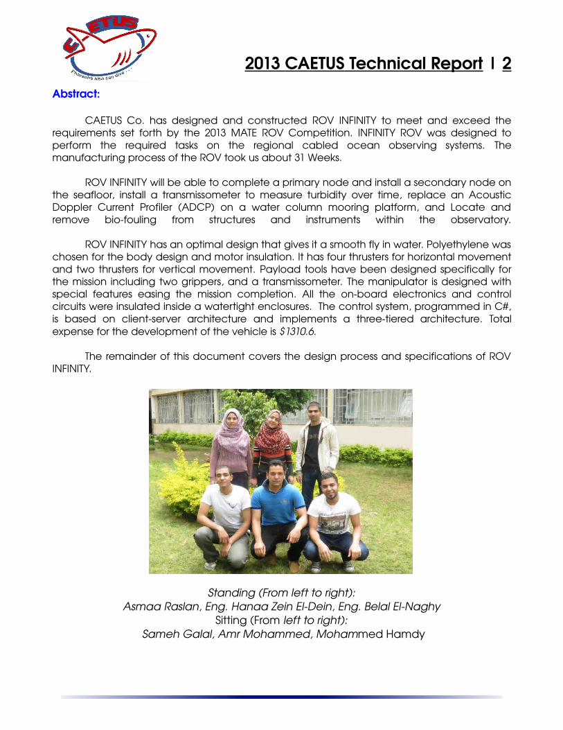
CAETUS Co. has designed and constructed ROV INFINITY to meet and exceed therequirements set forth by the 2013 MATE ROV Competition. INFINITY ROV was designed toperform the required tasks on the regional cabled ocean observing systems. Themanufacturing process of the ROV took us about 31 Weeks.
ROV INFINITY will be able to complete a primary node and install a secondary node onthe seafloor, install a transmissometer to measure turbidity over time, replace an AcousticDoppler Current Profiler (ADCP) on a water column mooring platform, and Locate andremove biofouling from structures and instruments within the observatory.
ROV INFINITY has an optimal design that gives it a smooth fly in water. Polyethylene waschosen for the body design and motor insulation. It has four thrusters for horizontal movementand two thrusters for vertical movement. Payload tools have been designed specifically forthe mission including two grippers, and a transmissometer. The manipulator is designed withspecial features easing the mission completion. All the onboard electronics and controlcircuits were insulated inside a watertight enclosures. The control system, programmed in C#,is based on clientserver architecture and implements a threetiered architecture. Totalexpense for the development of the vehicle is $1310.6.
The remainder of this document covers the design process and specifications of ROVINFINITY.
Standing (From left to right):Asmaa Raslan, Eng. Hanaa Zein ElDein, Eng. Belal ElNaghy
Sitting (From left to right): Sameh Galal, Amr Mohammed, Mohammed Hamdy

2013 CAETUS Technical Report | 3
Table of ContentsBUDGET AND FINANCIAL STATEMENT............................................................................................4
Sponsorship...........................................................................................................................................5Design Rationale........................................................................................................................................5
Frame.....................................................................................................................................................5Propulsion..............................................................................................................................................6CAMERA..............................................................................................................................................7HOUSING.............................................................................................................................................7MANIPULATOR..................................................................................................................................8
Electronic unit............................................................................................................................................8Motor Controller....................................................................................................................................8Power conversion..................................................................................................................................9LED Lights..........................................................................................................................................10Breakout Board....................................................................................................................................10TETHER..............................................................................................................................................10Tether Control Unit “TCU”.................................................................................................................11
SOFTWARE.............................................................................................................................................11Graphical User Interface.....................................................................................................................12Firmware.............................................................................................................................................13MAGNETOMETER ( LSM303DLH)................................................................................................13Joystick................................................................................................................................................14
Payload tools............................................................................................................................................14Task 1..................................................................................................................................................14Task 2..................................................................................................................................................14Task 3..................................................................................................................................................15Task 4..................................................................................................................................................16
Safety Procedures and Precautions..........................................................................................................16Challenges................................................................................................................................................16TROUBLESHOOTING TECHNIQUES.................................................................................................17Lessons Learned.......................................................................................................................................17Reflections...............................................................................................................................................18Future Improvements...............................................................................................................................19Acknowledgment.....................................................................................................................................19Teamwork and organization.....................................................................................................................20References................................................................................................................................................20Appendix A: Electrical block diagrams...................................................................................................21Appendix B: Circuit schematics...............................................................................................................23Appendix C: Programming flow chart.....................................................................................................25

2013 CAETUS Technical Report | 4
BUDGET AND FINANCIAL STATEMENT
* Item Quantity Price /unit ($) Total price ($)
Me
cha
nica
l
Thruster 13 20.3 263.9
Electronics Container 1 165.0 165
Polyethylene ROV body 120.0 120
Manipulator 2 25.0 50
Payload Electrical container 1 6.50 6.5
Glue and Sprays 5.40 5.4
Polyurethane Foam 8.10 8.1
Elec
tronic
s and
pa
yloa
d
Motor Driver 15 8.10 121.5
Power converter 3 14.8 44.4
PCB Sheet 12.2 12.2
Tether 20 M 40.2
Transmissometer 54.3 54.3
Led lights 2 4.1 8.2
Custom Electronics Component 43.2 43.2
Co
ntrol
Magnetometer (Compass) 1 36.5 36.5
Camera 3 202.7
Joystick 1 54.0 54.0
TCU 40.5 40.5
USB to Serial Converter 2 27.0 54.0
Easy Cap 2 10 20
Total ROV Expenses : $1310.6
Othe
rTOOL BOX 9.2 9.2
Screw driver box 4.3 4.3
Screw drivers 6.7 6.7
Power supply 81.0 81.0
Electrical joint 4.3 4.3
Tshirt 67.4 67.4
Transportation 150 150
Hadath registration 67.5 67.5
Air tickets and accomodation 8108 8108
Total Team Expenses: $1310.6+ $8498.4 = $9809

2013 CAETUS Technical Report | 5
Sponsorship
Name Amount
ElGhareeb charitable association $2000
Faculty of Engineering $7809
Total: $9809
Design Rationale
During the design phase we tried to design asimple and easy implemented ROV. We started tomake some sketches of probable designs. We got anidea of making the payload tools on a separateextension that can be easily connected/disconnectedfrom the ROV. We could summarize our design concept as follows:
1. Stability and efficiency.2. Strong and Smooth.3. Ease of implementation.4. Quick connect/disconnect capabilities.5. Ease of finding the required material.
Frame
The basis of the vehicle’s design is the frame. Itwas designed by SolidWorksTM 3D CAD software. Itconsists of four main component groups: the structuralskids (Fig.1), the payload extension (Fig.2), bouncy andelectronics container (Fig.3). The frame is made ofpolyethylene material because of polyethylenestrength, durability and less density than water, grantingthe ROV additional buoyancy. There are two oppositeplates forming the body and other two parallel platesfor the payload extension. There is a buoyancy madeof polyurethane foam mounted on top of the plates.We cut into the polyurethane foam to mount thevertical thrusters. The two plates are fixed together witha screw. There is also a metal grid for fixing payloadtools and horizontal thrusters, fixed between the twoplates. The frame is 60 CM(L), 45 CM(W), 30 CM(H) andthe extension is 50 CM(L), 45 CM(W), 15 CM(H). Theelectronic container will be discussed separately.
Fig.1: structural skids.
Fig.2: Payload Extension.
Fig.3: Electronics Container.
Fig.4: Frame Machining.

2013 CAETUS Technical Report | 6
Propulsion
Flying the ROV needs a force called thrust tobe greater than the total towing resistance. The towingresistance is the combination of forces working againstthe direction of motion. The main forces in this towingresistance are the total drag force.
We had three choices for the thruster; to modifya bilge pump, buy Seabotix thrusters or to isolate ourown motors. We chose to do the isolation ourselves tohave the balance between the thrust power andprice. The thrusters have proven power and reliability.
ROV INFINITY is driven by seven modifiedthrusters (Fig.5), five for the horizontal movement andother two for vertical movement. Two of the horizontalthrusters are responsible for forwardback moves andthe other two are responsible for leftright moves andcan be used to give more forwardbackward speed.The parts making the thruster is illustrated in (Fig.7).
CAETUS Co. decided to use polyethylene toisolate the motors. The polyethylene material ismachined to enclose the motor including a place to abearing and oil seal to prevent the water from leakinginto the enclosure. A cap with oring is machined toease the operation of replacing the motor in case ofany problem. The resulting heat was great and themotor would not last for even ten minutes and getburnt. The solution we get to is to fill the motorenclosure with oil and that did great. The motor wastested for an hour and there was no problems. We alsomachined a coupling to extend the motor shaft lengthconnecting the propeller. We bought a fourbladepropeller and after testing, we found that the load onthe motor was great so we modified the propeller tobe a twoblade and it worked great (Fig.8). Thepropeller did also great in reducing the heatgenerated by the motor. The thruster input and controlis discussed in the electronics and control part.
Fig.7: Thruster parts.
Fig.6: Side view of amounted thruster.
Fig.8: Propeller
Fig.5: Thruster enclosure.

2013 CAETUS Technical Report | 7
CAMERA
ROV INFINITY is equipped with three CCD (chargecoupled device) analog cameras, two 700TVL (PAL1024HX596V), and one with low resolution 420TVL. A CCDconsists of several hundred thousand individual pictureelements (pixels) on a tiny chip. Each pixel responds tolight falling on it by storing a tiny charge of electricity. Thepixels are arranged on a precise grid, with vertical andhorizontal transfer registers carrying the signals to thecamera's video processing circuitry. The cameras waschosen for reliability, low cost, small size, and high quality.The main front camera is an HST Eyeball PDI1224 (Fig.9)camera but we get the chip out of its enclosure and fix iton a discrete RC Servo motor moving updown to give avision angle 180 degree. The second main camera is HSTBullet IR1224 ( Fig.10) and it is fixed back the ROV anddirected to the middle bottom for the ROV to give ascenes of what the pilot doing while making the tasksand missions. The third camera with low quality is fixed togive a vertical view. Switching between cameras is doneby the pilot for the needed camera. The three camerassignals are transmitted through twisted pairs of anEthernet cable. Cameras were put into the electroniccontainer for safe housing. CAETUS Co. used an easycap adapter to convert analog camera streaming datato be read by USB port of a computer.
HOUSING
Containers for the electronic component designedto withstand the pressure. Housing made of opticallyclear acrylic tube with two aluminum ends to close thetube (See Fig.11 for installed container). Metal glands aremounted on both the two aluminum ends for all cableconnections (Fig.12). The tube has an outside diameterof 15CM and sealed by dual Orings on each side. Theelectronics container is mounted in the front upperportion of the ROV to provide additional buoyancy andallow the camera within the can the maximum field ofview. Electronic unit container is noteworthy, it iscomplex, but at the same time, the logical structure.Inside the container, multiple devices provide voltage
Fig.9: PDI1224 Eyeball
Fig.10: IR1224 Bullet IR
Fig.12: Early stage ofelectrical connections.
Fig.11: Infinity Verticalview.

2013 CAETUS Technical Report | 8
conversion, communications to the surface, thrustercontrol and data acquisition. Another electronicscontainer is made of a plastic food container for thepayload electronics (Fig.13).
MANIPULATOR
ROV INFINITY has two fixed manipulators (Fig.14) toperform general gripping needs easily and efficiently. Wehave fixed the manipulators in the ROV front center, andbottom center. Instead of depending on a movingmanipulator, the ROV’s thruster layout is able to pitch upand down and so we can move the ROV to the requiredposition. To create higher friction and ensure that thereare no sharp edges at the gripping point, the tip of themanipulator is wrapped in rubber that gives a rubberizedtexture.
The manipulator was made from polyethylenematerial due to its strength. It is powered by an isolatedmotor with the same concept of our thruster isolation. Apower screw is fixed on the motor shaft leading the groupand so the only movement comes from the motor (selflock).
Electronic unit
The electronic unit is like a human heart, it drives all other units and systems toprecisely perform the orders of the pilot. Control signals to the electronics componentare passed through the controller board, based on ARDUINO microcontrollerproviding complete user control over all of the ROV subsystems, including thrusters,video cameras, LED lighting, and payload tools. The tether communication protocolused is RS485 providing noise immunity due to the differential pairs used. The vehiclerequires three DCDC converters, one for each thrusters side of the ROV and one forthe logical control. The onboard HBridge only requires a PWM input to give therequired direction controlling the thruster. The cameras stream is sent via a separateEthernet cable to lower the interference as possible.
Motor Controller
CAETUS Co. decided to create a new motorcontroller (Fig.15) which is a device that serves to governin some predetermined manner the performance of anelectric motor. A motor controller includes starting and
Fig.15: Motor Driver.
Fig.14: Manipulator
Fig.13: Payload Electricalcontainer.

2013 CAETUS Technical Report | 9
stopping the motor, selecting forward or reverserotation, regulating the motor speed, and protectingagainst overloads and faults. An HBridge structure isused and it is an electronic circuit that enables avoltage to be applied across a load in eitherdirection, allowing the motor to run forward andbackward. The term Hbridge is derived from thetypical graphical representation of such a circuit(Fig.16). The Hbridge is built with four solidstateswitches (NCH and PCH MOSFETs). Using thenomenclature above, the switches in series shouldnever be closed at the same time, as this wouldcause a short circuit on the input voltage source.
The MOSFET driver was made using operationalamplifiers. The voltage translation is done bycomparing the logic level inputs to 2.5V generatedwith a voltage divider. If the microcontrollers outputis higher or lower than 2.5V then the appropriate NCH and PCH MOSFET will be turned on or off givingthe voltage direction.
Speed is controlled by holding one input lowand PWM the other input. Opto couplers are usedfor transmission of the PWM output of the microcontroller isolating the microcontroller ground fromthe motor voltage supply, protecting it from anydamages and increasing the safety and reliability ofthe circuit. The optocoupler consists of an LED and aphototransistor in the same package.
The circuit is working with 24V input voltage and can stand 7A current without aheat sink. If a heat sink is added it can handle much more current, but our companypreferred not to as the MOSFET retained the current and the circuit size is reduced.
A fly back diodes were added to maintain the back EMF (Electromotive Force),preventing it from damaging the MOSFETS. Counter EMF is a voltage developed in aninductor reversing the voltage polarity by its terminals at every moment the inputvoltage reversed. See (Fig.17) for the PCB design.
Power conversion
ROV INFINITY has been supplied with two DCDC Converters designed by thecompany to output 12, 24 Volts. The maximum load of the 24V is 24A and the 12V is7A. The 24V is designated to power the motors and the 12V to power the microcontroller, cameras, LED lights and an RC servo motor. We have used a Zener diode in
Fig.16: HBridge structure
Fig.17: Hbridge PCB layout
2013 CAETUS Technical Report | 10
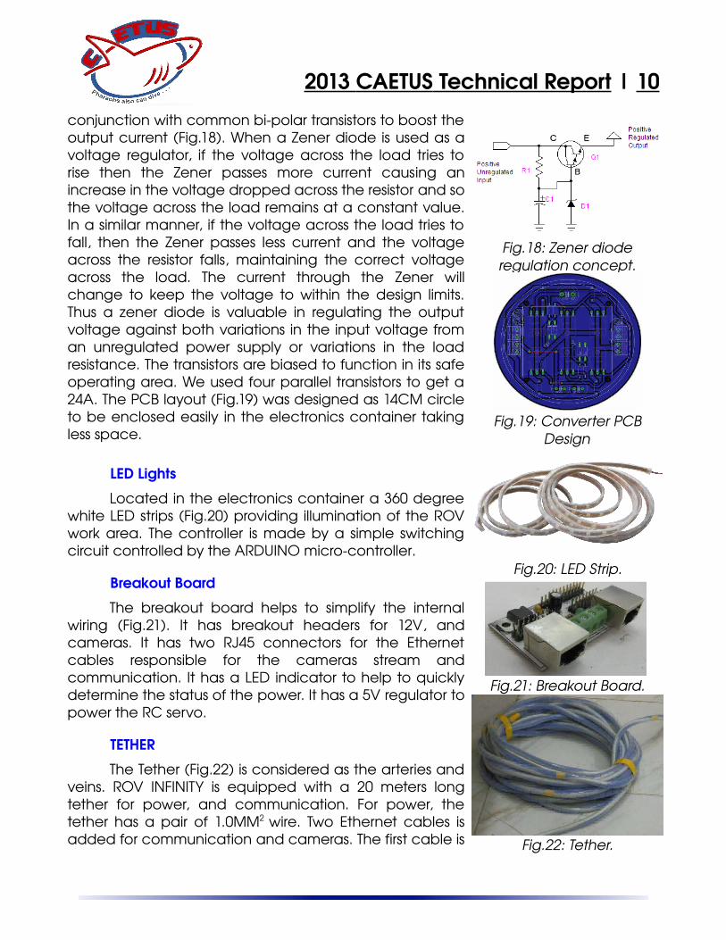
conjunction with common bipolar transistors to boost theoutput current (Fig.18). When a Zener diode is used as avoltage regulator, if the voltage across the load tries torise then the Zener passes more current causing anincrease in the voltage dropped across the resistor and sothe voltage across the load remains at a constant value.In a similar manner, if the voltage across the load tries tofall, then the Zener passes less current and the voltageacross the resistor falls, maintaining the correct voltageacross the load. The current through the Zener willchange to keep the voltage to within the design limits.Thus a zener diode is valuable in regulating the outputvoltage against both variations in the input voltage froman unregulated power supply or variations in the loadresistance. The transistors are biased to function in its safeoperating area. We used four parallel transistors to get a24A. The PCB layout (Fig.19) was designed as 14CM circleto be enclosed easily in the electronics container takingless space.
LED Lights
Located in the electronics container a 360 degreewhite LED strips (Fig.20) providing illumination of the ROVwork area. The controller is made by a simple switchingcircuit controlled by the ARDUINO microcontroller.
Breakout Board
The breakout board helps to simplify the internalwiring (Fig.21). It has breakout headers for 12V, andcameras. It has two RJ45 connectors for the Ethernetcables responsible for the cameras stream andcommunication. It has a LED indicator to help to quicklydetermine the status of the power. It has a 5V regulator topower the RC servo.
TETHER
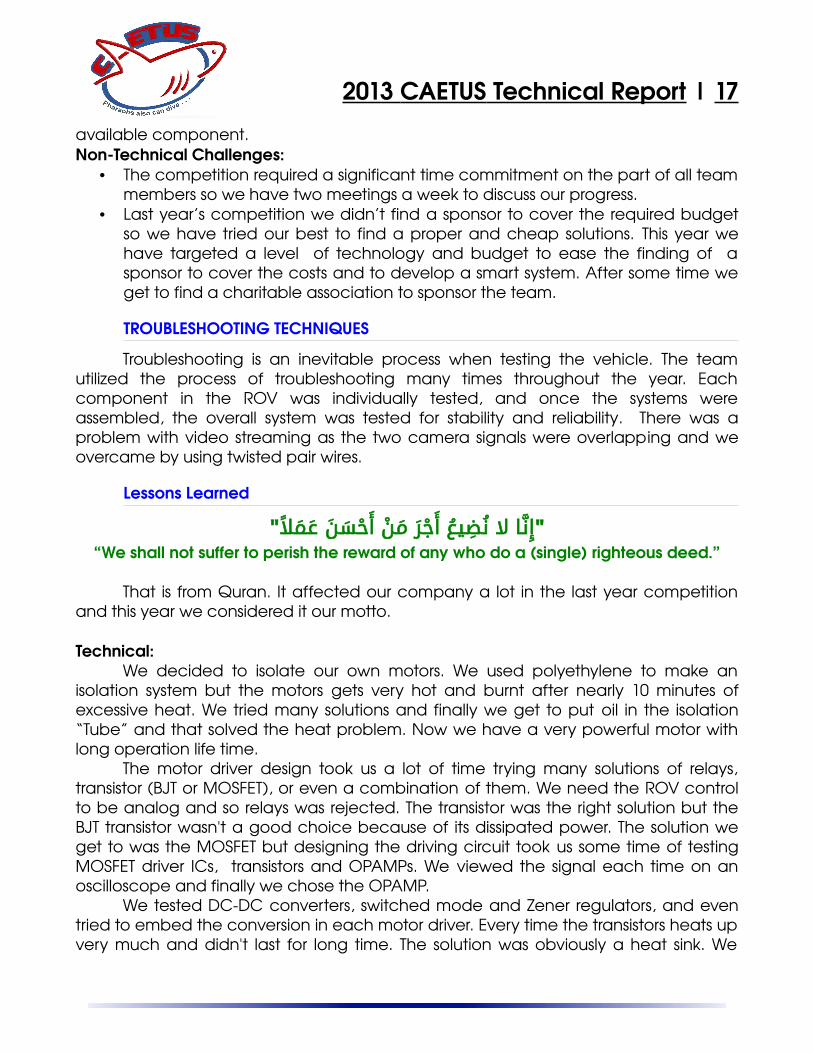
The Tether (Fig.22) is considered as the arteries andveins. ROV INFINITY is equipped with a 20 meters longtether for power, and communication. For power, thetether has a pair of 1.0MM2 wire. Two Ethernet cables isadded for communication and cameras. The first cable is
Fig.21: Breakout Board.
Fig.22: Tether.
Fig.18: Zener dioderegulation concept.
Fig.20: LED Strip.
Fig.19: Converter PCBDesign

2013 CAETUS Technical Report | 11
directed to communication (RS485) and connecting the power to the 12V DCDCconverter. The other Ethernet cable is used to transmit the cameras signal via twotwisted pairs. To make the tether neutrally buoyant, a strip of foam is fixed along itslength. To protect the tether and make it easier to manage, we added a spiral wrapalong the tether.
Tether Control Unit “TCU”
TCU is used to separate tether into different lines:power, control and video. 48V from power supplycomes to the TCU unit through the main fuse, whichprotects the circuit against excess current. The power issupplied to the TCU through a switch. The video signalpasses through the easy cap over an Ethernet cableand then appears as a part of GUI on the computerscreen. Control signals are transmitted between theoperator console on the surface and the electronicunit onboard via an Ethernet cable through RS485serial protocol. It also contains a USB hub to connectthe two easy cap, USB to RS485 serial converter, andRS485 communication circuit. The TCU has also panelmeter to give feedback about the voltage suppliedand the current drawn by the ROV. See (Fig.23, 24) forTCU.
SOFTWARE
CAETUS Co. has developed a proprietary controlsystem for ROV INFINITY using C# object oriented programming language, a clientserver interface is setup using the Windows Communication Foundation framework.This framework allows real time communication and data transfer betweenapplication logic acting as the server and user interface as a client .
ROV INFINITY control system consists of 3 major branches controller, joystick, andserial communication. The data is sent from the computer to the Arduino to processthe data. The Arduino is considered as system server and the computer is the client.Data transmitting is done using RS485 protocol through MAX485 and an Ethernetcable is used for transmitting. The whole component of ROV can be controlled fromthe Joystick such, flying in all directions (forward, backward, up, down, right, leftrotating CW, rotating CCW), controlling camera servo angle, lights, the manipulator.
Fig.23: TCU Front view.
Fig.24: TCU Back view.

2013 CAETUS Technical Report | 12
Graphical User Interface
The graphical user interface (GUI) should give the pilot all the abilities neededto smoothly operate the vehicle and help him get all the tasks perfectly done withsimple, attractive and comfortable design. The GUI based on window basedconcept. The GUI is divided into four main windows: cameras view, Joystick simulation,serial data transmission (Read, Write) and finally sensors control view. The GUIcommunicates with the ROV system through the topsides computer service bysending and receiving a series of serialized objects. Important information is alwaysclearly visible for the pilot.
The joystick is totally simulated on the GUI to ensure proper moves. Progress barsimulation is added for X, Y axis to show the scaled movement values sent to themotor drivers. The joystick can be started/stopped from GUI or from keyboard buttons.
The cameras have a separate views with small frames size for each one whichcan be separately running independent of each other. The GUI has a forth maincamera view with large frame size to switch between the small cameras views for abigger view which gives the pilot a clear and accurate ROV monitoring. Switchingbetween cameras is done with different frame sizes according to selected camerawhich was a challenge process but we done it very successfully. All cameras controland switch can be done from specified keyboard buttons and from menu options inthe GUI. The camera stream can also be recorded.
Fig.25: ROV Infinity Graphical User Interface.

2013 CAETUS Technical Report | 13
The serial control menu allows to choose the communication port and controlthe transmission speed choosing the required baud rate. For sending joystickmovement control values from client (GUI) to server (ARDUINO) to apply thesemovements on the designated motors. The GUI can receive data from server on arich box which can view messages providing feedback about motors for whichworked, these data also can be sensors reading for temperature, compass, depthand acceleration.
Firmware
The firmware performs determined functionssending/receiving packets through the certain protocols,controlling the ROV, and collecting data from the sensors.An Arduino mega ADK is used as controller because it’srich features like 54 digital I/O (of which 15 provide PWMoutput), 16 A/D pins, 4 serial modules and other features.
MAGNETOMETER ( LSM303DLH)
The LSM303DLH (Fig.27) is a triple axismagnetometer (Compass) combined with a triple axisaccelerometer. This breakout board uses the LSM303DLHto give data we need to feed into a microcontroller orArduino and calculate Compass tiltcompensated andmore accurate output. Traditional compass needs to beheld flat (in horizontal plane) and it is a problem as thecompass is only using the X and Y axis of the earthmagnetic field. When the compass is not parallel to theseaxis the amount of magnetism will change based on how the alignment of compassis to those axises. The third axis, Z, which (when tilted) now collects the magnetic fieldlost by X and Y when they are tilted out of alignment measuring the gravitycomponent G.
Fig.26: Arduino MegaADK
Fig.27: Magnetometer

2013 CAETUS Technical Report | 14
Joystick
Logitech Extreme™ 3D Pro Joystick was chosen by thecompany for its proper design. It gives the pilot comfortableand easy flying enabling him to control the speed of the ROV.The joystick has analog readouts in X, Y, Z axis, digital buttonsand a slider.
Payload tools
CAETUS Co. have considered to design the proper tools to successfully operatein all the required missions. We have designed two manipulators to get the job done.The primary manipulator is fixed in front of the ROV and the secondary one is fixedunder the ROV to be able to carry the different parts to its designated destination. Acamera fixed inside the ROV to be able to monitor the secondary manipulator doingits job.
Task 1
Complete a primary node and install a secondary node on the seafloor.The first task includes an extensive list of subtasks. The Science Interface
Assembly (SIA) will be given to the company and then it will be fixed in the secondarymanipulator and be carried to be completely rested within the Backbone InterfaceAssembly (BIA). We will be searching for the Cable Termination Assembly (CTA) inrange of two meters around the BIA and when found it will be carried to be insertedinto the bulkhead connector on the BIA. The pin of the secondary node will bereleased from the elevator and so we can remove it from the elevator. It will becarried to the designated location after measuring the required distance.
Two motors are installed in the ROV to adjust the level of the secondary nodemonitoring the level of the circular bubble via the camera. The company will be ableto open the door using the primary manipulator. Then at last we will remove thesecondary node cable connector from the elevator and insert it in into the bulkheadconnector on the SIA.
Task 2
Design, construct, and install a transmissometer to measure turbidity over time. ROV INFINITY will be able to carry the transmissometer which is a device for
measuring the attenuation of light as it travels through water to measure the turbidityin the ocean. The instrument consists of a light source of known frequency andintensity which is a laser beam of class IIIa (650nm, 5W) and a detector which is aphototransistor located at a known distance. The signal is then amplified with an
Fig.28: Joystick.
2013 CAETUS Technical Report | 15
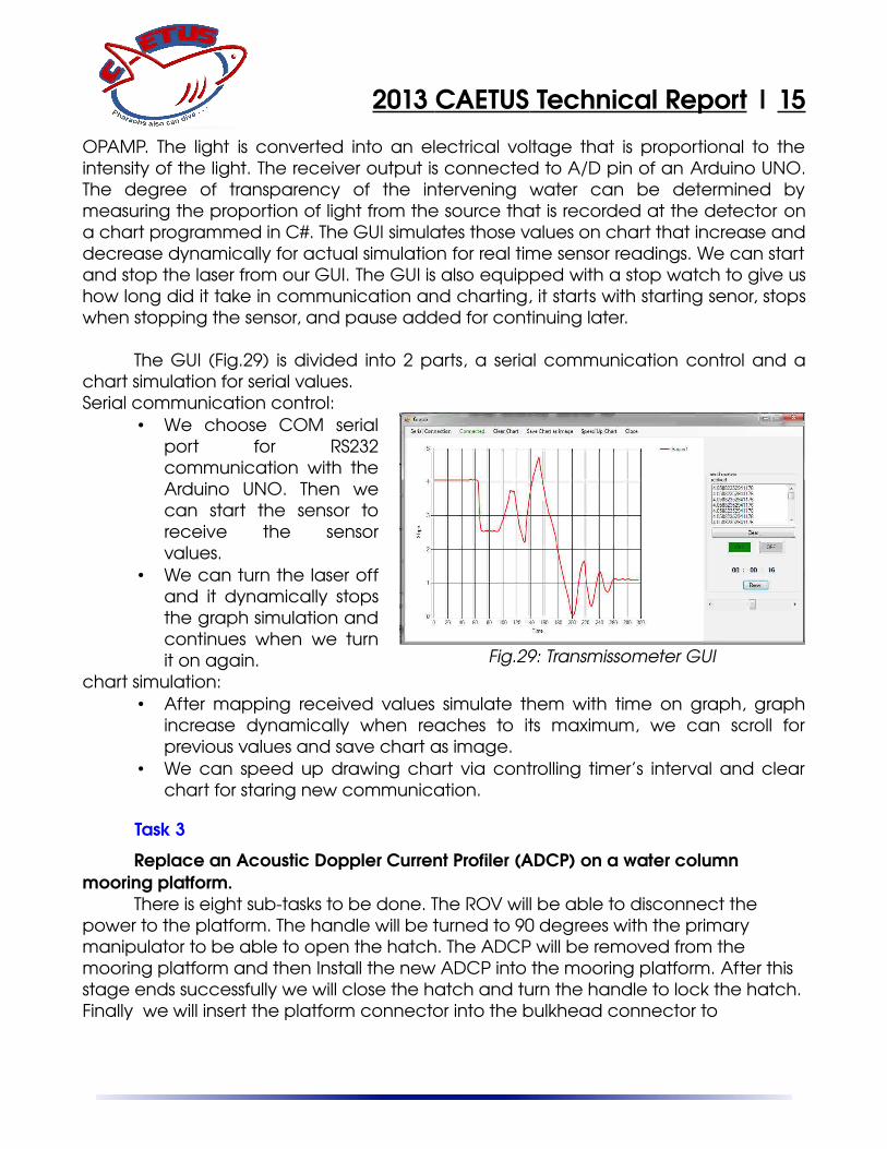
OPAMP. The light is converted into an electrical voltage that is proportional to theintensity of the light. The receiver output is connected to A/D pin of an Arduino UNO.The degree of transparency of the intervening water can be determined bymeasuring the proportion of light from the source that is recorded at the detector ona chart programmed in C#. The GUI simulates those values on chart that increase anddecrease dynamically for actual simulation for real time sensor readings. We can startand stop the laser from our GUI. The GUI is also equipped with a stop watch to give ushow long did it take in communication and charting, it starts with starting senor, stopswhen stopping the sensor, and pause added for continuing later.
The GUI (Fig.29) is divided into 2 parts, a serial communication control and achart simulation for serial values.Serial communication control:
• We choose COM serialport for RS232communication with theArduino UNO. Then wecan start the sensor toreceive the sensorvalues.
• We can turn the laser offand it dynamically stopsthe graph simulation andcontinues when we turnit on again.
chart simulation:• After mapping received values simulate them with time on graph, graph
increase dynamically when reaches to its maximum, we can scroll forprevious values and save chart as image.
• We can speed up drawing chart via controlling timer’s interval and clearchart for staring new communication.
Task 3
Replace an Acoustic Doppler Current Profiler (ADCP) on a water column mooring platform.
There is eight subtasks to be done. The ROV will be able to disconnect the power to the platform. The handle will be turned to 90 degrees with the primary manipulator to be able to open the hatch. The ADCP will be removed from the mooring platform and then Install the new ADCP into the mooring platform. After this stage ends successfully we will close the hatch and turn the handle to lock the hatch.Finally we will insert the platform connector into the bulkhead connector to
Fig.29: Transmissometer GUI

2013 CAETUS Technical Report | 16
successfully reconnect the power monitoring the bolts of the platform connector protrude through the holes in the bulkhead connector.
Task 4
Locate and remove biofouling from structures and instruments within the observatory. We will search for the different organisms and remove it using the manipulator during the whole mission time.
Safety Procedures and Precautions
Safety is one of the most important standards that have been taken intoaccount during the stages of building ROV INFINITY. It was a major concern of CAETUSCo. throughout the whole process of design, building, development and testing ofthe ROV. The ROV INFINITY has a number of safety features including:
• Designing the vehicle frame to be smooth, with no sharp edges.• Completely shrouded thrusters and using appropriate materials in the isolation.• Warning labels located near moving parts and electrical hazards.• Overcurrent protection via a main inline fuse on the tether at the surface.• Killswitch for emergency stoppage.• Fuse before each motor to protect the other system component.• Electrical isolation of the high power motor component and the low voltage
electronic component.• Safety rope to avoid breakage or damage.
Operational and transporting precautions • Life jackets and safety glasses required for all company employees.• Training and practice in safety precautions.• Protocol in a predive check operations.
Challenges
While designing the vehicle, we have decided to create something special,something smart, reliable and capable of performing mission tasks with ease. Themost technical challenge was the isolation of circuits and cameras so we decided tomanufacture an electronics container with waterproofed ends. The motor isolationtook much time of troubleshooting.
The biasing circuit of the MOSFET, we tried many ways to make it includingtransistors, transistor array chips ,MOSFET driver chips and OPAMP. The best cheapand reliable method was OPAMP after checking the signal on an oscilloscope.Choosing the operating PWM frequency of the motor driver, we set a table and triedmany frequencies and finally we came to a decision. The lack of finding the requiredcomponent in Egypt made us change our design to meet the specifications of the
2013 CAETUS Technical Report | 17
available component.NonTechnical Challenges:
• The competition required a significant time commitment on the part of all teammembers so we have two meetings a week to discuss our progress.
• Last year’s competition we didn’t find a sponsor to cover the required budgetso we have tried our best to find a proper and cheap solutions. This year wehave targeted a level of technology and budget to ease the finding of asponsor to cover the costs and to develop a smart system. After some time weget to find a charitable association to sponsor the team.
TROUBLESHOOTING TECHNIQUES
Troubleshooting is an inevitable process when testing the vehicle. The teamutilized the process of troubleshooting many times throughout the year. Eachcomponent in the ROV was individually tested, and once the systems wereassembled, the overall system was tested for stability and reliability. There was aproblem with video streaming as the two camera signals were overlapping and weovercame by using twisted pair wires.
Lessons Learned
"ِإّنل اع لع ُنِضعيُعع َأْجَرع َمْنع َأْحَسَنع َعَمًل"“We shall not suffer to perish the reward of any who do a (single) righteous deed.”
That is from Quran. It affected our company a lot in the last year competitionand this year we considered it our motto.
Technical:We decided to isolate our own motors. We used polyethylene to make an
isolation system but the motors gets very hot and burnt after nearly 10 minutes ofexcessive heat. We tried many solutions and finally we get to put oil in the isolation“Tube” and that solved the heat problem. Now we have a very powerful motor withlong operation life time.
The motor driver design took us a lot of time trying many solutions of relays,transistor (BJT or MOSFET), or even a combination of them. We need the ROV controlto be analog and so relays was rejected. The transistor was the right solution but theBJT transistor wasn't a good choice because of its dissipated power. The solution weget to was the MOSFET but designing the driving circuit took us some time of testingMOSFET driver ICs, transistors and OPAMPs. We viewed the signal each time on anoscilloscope and finally we chose the OPAMP.
We tested DCDC converters, switched mode and Zener regulators, and eventried to embed the conversion in each motor driver. Every time the transistors heats upvery much and didn't last for long time. The solution was obviously a heat sink. We
2013 CAETUS Technical Report | 18
tried a computer processor heat sink with the Zener regulator converter circuit andfinally we got a working and stable converter.
We faced a problem with sending the signals to control the ROV and transferthe cameras signal on the same cable. We needed something reliable and ease touse over at least 20M long. We decided to use an Ethernet cable for sending thecontrol signal using RS485 and used the a 4 wires of the same cable to send thecameras stream.
Interpersonal:The team gained a good experience from the last year contest but most of the
team graduated and so we needed a new members. We chose just a new memberand we had to pass him our experience to be on the same level. Every one of thethree of us was responsible for one sector of the ROV and we had to help each otherin different fields of interest.
The team members acts like one person and the team is above any otherconsiderations. We also learnt to work under very high tension and tight schedules.We had to know what parts we need and what do we need for subsequent workdays in order to put our schedule and to maintain it. The three members are fromdifferent departments and we had to work together in order to design and makemodifications.
Reflections
Amr MohammedLast year I was the team mechanical engineer, but this year the situation has
changed. I have very important role beside my previous one as team captain. It wasa huge responsibility on my shoulders. I acquired knowledge in very unfamiliar fields such as management and leadership.
Mohamed HamdyThanks to all our great mentors ,parents and especially MATE and Hadath for
making such a wonderful competition in Egypt. I am studying at the university tobecome a good communications Engineer, but I fond of the programming. Thiscompetition I had the opportunity to realize my potential of the programmer.It is the first time in my life when such a big responsibility is laying on me. Throughdealing with the team realized that one would not succeed if he do not sense a fullresponsibility incumbent upon him and deal with it. This experience made me moreorganized, disciplined and responsible.
Sameh GalalSameh is addicted to electronics and it was a great adventure for him to work
in power electronics and deal with such a current, voltage, and frequency.
2013 CAETUS Technical Report | 19
Interfacing circuits are the back bone of the whole system as it should satisfy both themechanical and programming requirements, that was a great load to make areliable and stable circuits. It was a great time and I had what I wanted to get whichis "FUN". Thanks to those who trusted me getting things done, specially if I am doingthings alone!
Future Improvements
Communication:Using Fiber optics for transmitting the data and camera stream on just one
cable. It has a small size and high speed which will benefit us to apply our control ondifferent cable lengths.Control system:
We will change the Arduino microcontroller to a credit card sized computer likea Raspberry PI or a Beagle Bone for more data handling and sensors. PID control willbe considered for stable ROV control.Electrical system:
We are willing to improve the motor driving circuits to handle more current andincrease its PWM frequency to get a lower vibration. We will also add more safetyfeatures to the driver circuit. The power converter also will be changed to switchedmode which will be much more stable and safe than zener regulator.
Acknowledgment
High performance teams do not result from nothing. But they are grown,nurtured and exercised under supervision. Thanks to Allah for giving us the chance tocompete and for the chance that our team worked together. We thank MATE centerand HADATH company for organizing the competition and giving us the chance tocompete with other teams. Thanks to the Arab Academy for Science, Technology &Maritime Transport for hosting the local competition.
We would like to extend our sincere gratitude to our great mentors Prof.Mohamed AbdElazem, Eng. Hanaa ZeenEldeen, Eng. Belal Shehata, Eng. AmeraMagde who found time in their schedule to share experience and give us feedbackon our progress which improved the final quality of the ROV. We also want to give Dr.Mohammed Fanni a special recognition of his work with us last year and hisencouragement for us in this year.
Thanks to our college for permitting us to work in a laboratory to give birth to ourROV. Special thanks to our parents and family for encouraging us to innovate and getour job done. We were not home for days and that even did not bother them. Wewant to give them our sincere appreciation. Thanks to Ahmed AboZeid, Anas Emad,Samar Ali, Adel Youssef, and Saad Zanfal.
Our most sincere thanks goes to ElGhareeb charitable association for coveringthe ROV expenses, and our college for covering the team travel expenses.
2013 CAETUS Technical Report | 20
Teamwork and organization
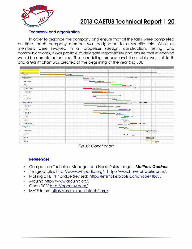
In order to organize the company and ensure that all the tasks were completedon time, each company member was designated to a specific role. While allmembers were involved in all processes (design, construction, testing, andcommunications), it was possible to delegate responsibility and ensure that everythingwould be completed on time. The scheduling process and time table was set forthand a Gantt chart was created at the beginning of the year (Fig.30).
References
• Competition Technical Manager and Head Rules Judge – Matthew Gardner.• The great sites http://www.wikipedia.org/ , http://www.howstuffworks.com/.• Making a FET "H" bridge (revised) http://letsmakerobots.com/node/18633.• Arduino http://www.arduino.cc/.• Open ROV http://openrov.com/.• MATE forum http://forums.marinetech2.org/.
Fig.30: Gannt chart
2013 CAETUS Technical Report | 21
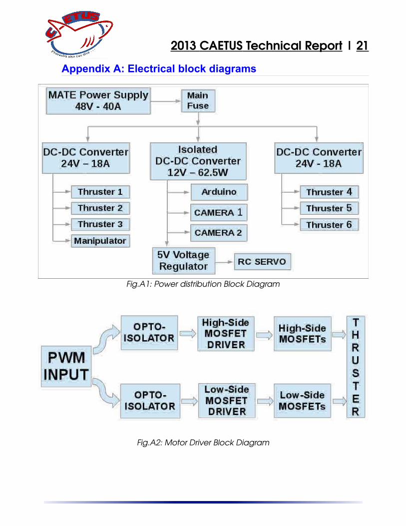
Appendix A: Electrical block diagrams
Fig.A1: Power distribution Block Diagram
Fig.A2: Motor Driver Block Diagram

2013 CAETUS Technical Report | 22
Fig.A3: Communication and Signals Block Diagram
Fig.A4: Transmissometer Block Diagram

2013 CAETUS Technical Report | 23
Appendix B: Circuit schematics
Fig.B1: Power converter schematic.
Fig.B2: Motor driver schematic.

2013 CAETUS Technical Report | 24
Fig.B3: Breakout board schematic.
Fig.B4: Transmissometer communicationcircuit.
Fig.B5: Transmissometer detector circuit.

2013 CAETUS Technical Report | 25
Appendix C: Programming flow chart
Fig.C: Programming flow chart.