by Orlando J. Hernandez, Ph.D. - TCNJhernande/Eng312/TCNJ_Verilog(R)_V06.pdf · Verilog Code for...
110
“A Verilog Overview” A Verilog Overview by Orlando J. Hernandez, Ph.D. Electrical & Computer Engineering School of Engineering THE COLLEGE OF NEW JERSEY
Transcript of by Orlando J. Hernandez, Ph.D. - TCNJhernande/Eng312/TCNJ_Verilog(R)_V06.pdf · Verilog Code for...

“A Verilog Overview”A Verilog Overviewby
Orlando J. Hernandez, Ph.D.Electrical & Computer Engineeringp g g
School of EngineeringTHE COLLEGE OF NEW JERSEY
Presentation OverviewPresentation Overview
Introduction to Verilog – Part I Introduction to Verilog – Part II
AND, OR, HALF ADDER, FULL ADDER Introduction to Verilog – Part IIIg
ALU Design Control and Data Path Organization
Finite State Machines, Digital Filter, g Q&A Sessions
2
Electrical & Computer EngineeringSchool of Engineering
THE COLLEGE OF NEW JERSEY

INTRODUCTION TO VerilogPART I
3
Electrical & Computer EngineeringSchool of Engineering
THE COLLEGE OF NEW JERSEY
Design AutomationDesign Automation
Need To Keep With Rapid Changes, Electronic Products Have To Be D i d E t l Q i klDesigned Extremely Quickly
Electronic Design Automation (EDA) Design Entry Simulation
S th i Synthesis Design Validation & Test
4
Electrical & Computer EngineeringSchool of Engineering
THE COLLEGE OF NEW JERSEY

Design Automation. Cont…Design Automation. Cont…
D i E t Design Entry Schematic Capture
Q
QSET
S
R
5
Electrical & Computer EngineeringSchool of Engineering
THE COLLEGE OF NEW JERSEY
QCLR
R

Design Automation. Cont…Design Automation. Cont…
Design Entry - Textual Form: Verilog VHDL (VHSIC Hardware Description
Language) VHSIC (Very High Speed Integrated
Circuits)
6
Electrical & Computer EngineeringSchool of Engineering
THE COLLEGE OF NEW JERSEY

Design Automation. Cont…Design Automation. Cont…
Design Entry - Textual Form:
module and_2 (X, Y, Z);input X Y;input X, Y;output Z;
assign Z = X & Y;endmodule
7
Electrical & Computer EngineeringSchool of Engineering
THE COLLEGE OF NEW JERSEY

Introduction To VerilogIntroduction To Verilog
Verilog Is an Industry Standard Language to Describe Hardware From the Abstract to Concrete Level.
8
Electrical & Computer EngineeringSchool of Engineering
THE COLLEGE OF NEW JERSEY

BRIEF HISTORY OF VerilogBRIEF HISTORY OF Verilog
i d b C d Began as a proprietary HDL promoted by Cadence Design Systems.
Cadence transferred control of Verilog to a consortium of companies and universities known as Open Verilog International (OVI).
Verilog is an IEEE Standard (IEEE Standard 1364-1995).
Verilog continues to be extended and upgraded (IEEE Standard 1364-2000, System Verilog).
9
Electrical & Computer EngineeringSchool of Engineering
THE COLLEGE OF NEW JERSEY
, y g)

MOTIVATIONMOTIVATION
Need a Method to Quickly Design, Implement, Test and Document I i l C l Di it l S tIncreasingly Complex Digital Systems.
Schematic and Boolean Equations Inadequate for Million-Gate ICs.
Design Portability
10
Electrical & Computer EngineeringSchool of Engineering
THE COLLEGE OF NEW JERSEY
What is Verilog?What is Verilog?
A Design entry language A Simulation modeling language.A Simulation modeling language. A Verification language.
A Standard language A Standard language. As simple or complex as required.
11
Electrical & Computer EngineeringSchool of Engineering
THE COLLEGE OF NEW JERSEY

How is Verilog Used?How is Verilog Used?
For Design Specification (“Specify”) Specify
For Design Entry (“Capture”)
Fo Design Sim lation (“Ve if ”)
Capture
Verify For Design Simulation (“Verify”)
For Design Documentation (“Formalize”)
Verify
Formalize For Design Documentation ( Formalize )
As an Alternate to Schematics
Formalize
Implement
12
Electrical & Computer EngineeringSchool of Engineering
THE COLLEGE OF NEW JERSEY
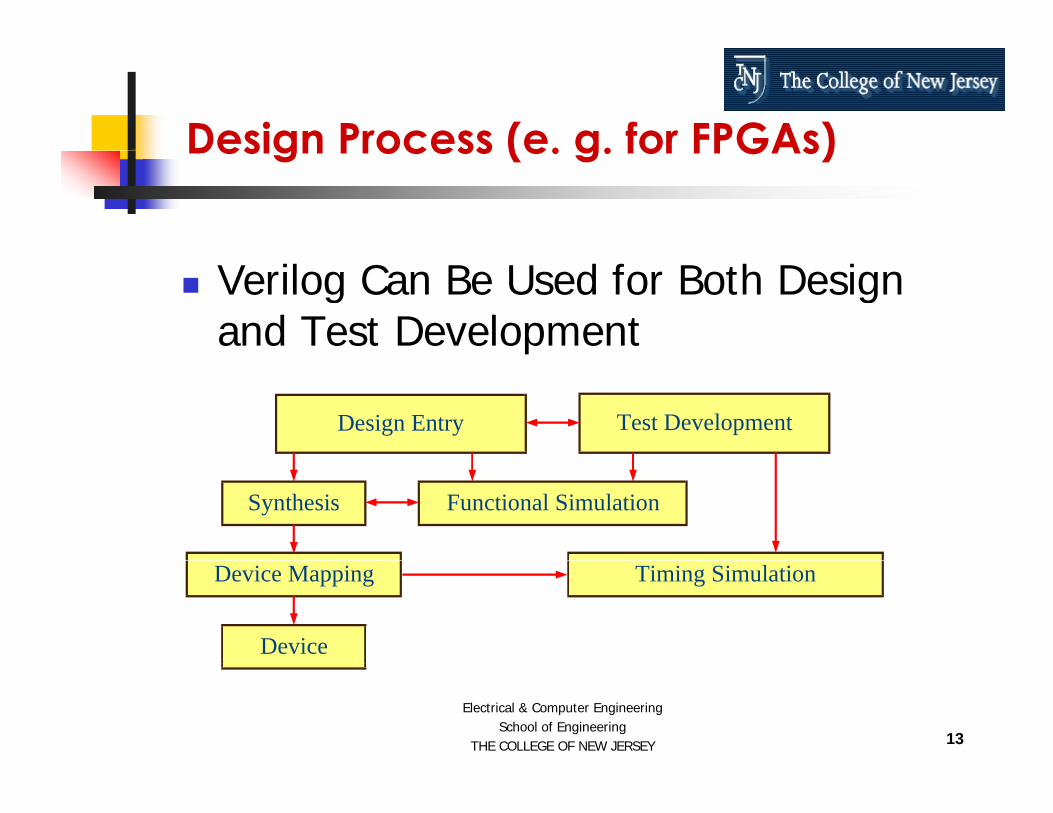
Design Process (e. g. for FPGAs)Design Process (e. g. for FPGAs)
Verilog Can Be Used for Both Design and Test Development
Design Entry Test Development
Synthesis Functional Simulation
Device Mapping Timing Simulation
Device
13
Electrical & Computer EngineeringSchool of Engineering
THE COLLEGE OF NEW JERSEY

When Should Verilog Be Used?When Should Verilog Be Used?
Verilog is highly beneficial to use as a structured, top down approach to design.
Verilog makes it easy to build, use, and e og a es t easy to bu d, use, a dreuse libraries of circuit elements.
Verilog can greatly improve your Verilog can greatly improve your chances of moving into more advanced tools and design flows
14
Electrical & Computer EngineeringSchool of Engineering
THE COLLEGE OF NEW JERSEY
tools and design flows.

Advantages of VerilogAdvantages of Verilog
The Ability to Code the Behavior and to Synthesize an Actual Circuit.
Power and Flexibility
Device (specific FPGA) Independent Design
Technology (specific silicon process) Independent Design
15
Electrical & Computer EngineeringSchool of Engineering
THE COLLEGE OF NEW JERSEY
p g

Advantages of Verilog Cont…Advantages of Verilog Cont…
Portability Among Tools and Devices
Fast Switch Level Simulations
Quick Time to Market and Low Cost
Industry Standard
16
Electrical & Computer EngineeringSchool of Engineering
THE COLLEGE OF NEW JERSEY
y

Getting Started with VerilogGetting Started with Verilog
Its Easy To Get Started With Verilog, But It Can Be Difficult To Master It.
To Begin With, A Subset of The Language Can Be Learned To Write U f l M d lUseful Models.
Later, More Complex Features Can Be L d T I l t C lLearned To Implement Complex Circuits, Libraries, And APIs.
17
Electrical & Computer EngineeringSchool of Engineering
THE COLLEGE OF NEW JERSEY

A First look at VerilogA First look at Verilog
Lets start with a simple Combinational circuit: an 8-bit Comparatorcircuit: an 8 bit Comparator.
18
Electrical & Computer EngineeringSchool of Engineering
THE COLLEGE OF NEW JERSEY

An 8 Bit ComparatorAn 8 Bit Comparator
Comparator Specifications: Two 8-bit inputsp 1-bit Output Output is 1 if the inputs match or 0 if they p p y
differ.
19
Electrical & Computer EngineeringSchool of Engineering
THE COLLEGE OF NEW JERSEY

An 8 Bit ComparatorAn 8 Bit Comparator
Comparator
A[8]
EQB[8] EQB[8]
0 1 2 3 4 5 6 7A 1 0 1 1 0 0 1 1
20
Electrical & Computer EngineeringSchool of Engineering
THE COLLEGE OF NEW JERSEY
B 1 0 1 1 0 0 1 1

Comparator Verilog Source Code
// Eight-bit Comparator
Comparator Verilog Source Code
module compare (A, B, EQ)input [7:0] A, B;output EQ;output EQ;
assign EQ = (A == B);endmodule
Define the inputs and outputs - the ports of the circuit
21
Electrical & Computer EngineeringSchool of Engineering
THE COLLEGE OF NEW JERSEY
p p pDefine the function of the circuit

What is a moduleWhat is a module
Every Verilog design description has at least one module construct.
A large design has many modules and are connected to form the complete circuitconnected to form the complete circuit.
The module port declarations describe theThe module port declarations describe the circuit as it appears from “outside”- from perspective of its input and output interfaces.
22
Electrical & Computer EngineeringSchool of Engineering
THE COLLEGE OF NEW JERSEY

What is a module?
d l (A B EQ)
What is a module?
module compare (A, B, EQ)input [7:0] A, B;output EQ;
:::
The module and port declarations includes a name, The module and port declarations includes a name, compare, and port direction statements defining all the inputs and outputs of the module.
The Rest of the module Describes the Actual Function.
23
Electrical & Computer EngineeringSchool of Engineering
THE COLLEGE OF NEW JERSEY

What is a module?What is a module?
::
assign EQ = (A == B);assign EQ (A B);endmodule
Before the keyword endmodule is found the actual functional description of thethe actual functional description of the comparator.
24
Electrical & Computer EngineeringSchool of Engineering
THE COLLEGE OF NEW JERSEY

Data TypesData Types
Verilog’s high level data types allow data to be represented in much the same way as in high-level programming languages.
A data type is an abstract A data type is an abstract representation of stored data.
25
Electrical & Computer EngineeringSchool of Engineering
THE COLLEGE OF NEW JERSEY

Data TypesData Types
These data types might represent individual wires in a circuit, or a collection of wires.
26
Electrical & Computer EngineeringSchool of Engineering
THE COLLEGE OF NEW JERSEY

Data TypesData Types
B i D T Basic Data Types Nets
wire, wand, tri, wor Continuously driven Gets new value when driver changes LHS of continuous assignment
tri [15:0] data;// unconditional
assign data[15:0] = data_in;// conditional
assign data[15:0] = enable ? data_in : 16’bz;R i t Registers
Reg Represents storage Always stores last assigned value LHS of an assignment in a procedural block
reg signal;reg signal;@(posedge clock) signal = 1’b1;
// possitive edge@(reset) signal = 1’b0; // event (both edges)
27
Electrical & Computer EngineeringSchool of Engineering
THE COLLEGE OF NEW JERSEY

Some Data TypesData Type Values Examples
Some Data Types
BitArray of bitsB l
'1' , '0' , 'x' , 'z'"101001"U Bit
Q = 1’b1;Data[5:0] = 6’b101001;EQ 1’b1 // TBoolean
IntegerReal
Use Bit-2, -1, 0, 1, 2, 31 0 -1 0E5
EQ = 1’b1; // TrueC = c+2;V1 = V2/5 3;Real
Time1.0, 1.0E5‘timescale 1ns/1ps
V1 V2/5.3;#6 Q = 1’b1;
Register Single or array of bitsCharacterString
Use 8-bit registerUse register of length 8 x the # of characters
g g y
28
Electrical & Computer EngineeringSchool of Engineering
THE COLLEGE OF NEW JERSEY

Design UnitsDesign Units
Design units are a concept that provide advanced configuration management capabilities.
Design units are modules of Verilog that can be compiled separately and storedcan be compiled separately and stored in a library.
29
Electrical & Computer EngineeringSchool of Engineering
THE COLLEGE OF NEW JERSEY

Library Design unitLibrary Design unit
A Library is a collection of commonly used modules to be used globally among different design units.
Library is identified with compiler/simulator command linecompiler/simulator command line switches.
30
Electrical & Computer EngineeringSchool of Engineering
THE COLLEGE OF NEW JERSEY

Levels of Abstraction (Styles)Levels of Abstraction (Styles)
Verilog supports many possible styles of design description.
These styles differ primarily in how These styles differ primarily in how closely they relate to the underlying hardwarehardware.
31
Electrical & Computer EngineeringSchool of Engineering
THE COLLEGE OF NEW JERSEY

Levels of Abstraction (Styles)Levels of Abstraction (Styles)
Levels of Abstraction refers to how far your design description is from an actual hardware realization.
The three main levels of abstraction e t ee a e e s o abst act oare: Behavior Behavior Dataflow Structure
32
Electrical & Computer EngineeringSchool of Engineering
THE COLLEGE OF NEW JERSEY
Structure
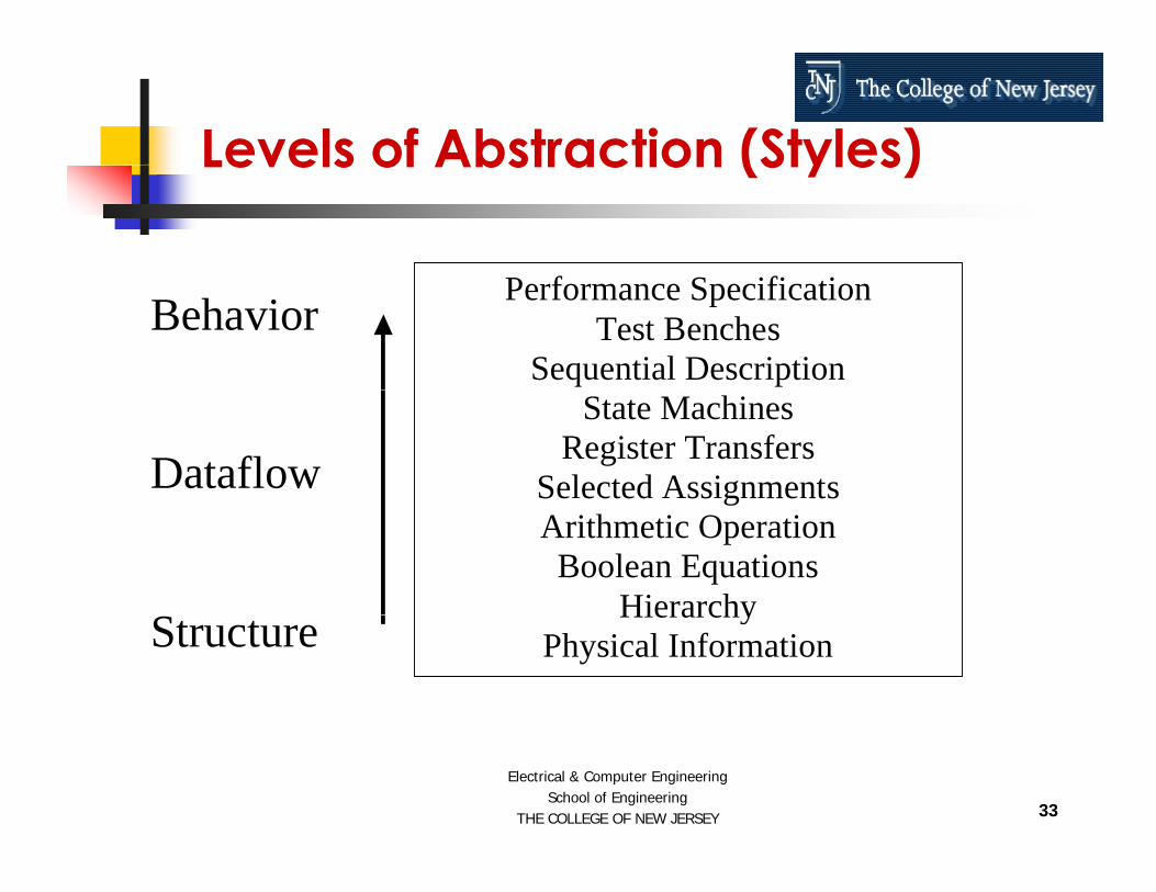
Levels of Abstraction (Styles)
P f S ifi i
Levels of Abstraction (Styles)
Behavior
Performance SpecificationTest Benches
Sequential Description Dataflow
State MachinesRegister Transfers
Selected Assignments
gArithmetic Operation
Boolean Equations HierarchyStructure
HierarchyPhysical Information
33
Electrical & Computer EngineeringSchool of Engineering
THE COLLEGE OF NEW JERSEY

Behavioral ModelingBehavioral Modeling
The Highest Level of Abstraction Supported in Verilog.
The Behavior Approach Describes the The Behavior Approach Describes the Actual Behavior of Signals Inside the ComponentComponent.
34
Electrical & Computer EngineeringSchool of Engineering
THE COLLEGE OF NEW JERSEY

Verilog Timing IssuesVerilog Timing Issues
The Concept of Time Is the Critical Distinction Between Behavioral Descriptions and Low Level Descriptions.
The Concept to Time May Be Expressed The Concept to Time May Be Expressed Precisely, With Actual Delays Between Related Events
35
Electrical & Computer EngineeringSchool of Engineering
THE COLLEGE OF NEW JERSEY
Related Events

A E l f B h i l M d li A h lf ddAn Example of Behavioral Modeling: A half adder
sumsuma
carryb
36
Electrical & Computer EngineeringSchool of Engineering
THE COLLEGE OF NEW JERSEY

half adderhalf_adder
Half Adder Inputs a, b : 1 bit each.Inputs a, b : 1 bit each. Output Sum, Carry : 1 bit each.
suma
b
carry
Figure 1-1 Half adder circuit
37
Electrical & Computer EngineeringSchool of Engineering
THE COLLEGE OF NEW JERSEY

Verilog Code for half adderVerilog Code for half_adder
// H lf Add// Half Addermodule half_adder (a, b, sum, carry);
input a, b;output sum carry;output sum, carry;
reg sum, carry;
always @ (a or b) beginsum = a ^ b;carry = a & b;y ;
endendmodule
38
Electrical & Computer EngineeringSchool of Engineering
THE COLLEGE OF NEW JERSEY
INTRODUCTION TO VerilogPART II
39
Electrical & Computer EngineeringSchool of Engineering
THE COLLEGE OF NEW JERSEY
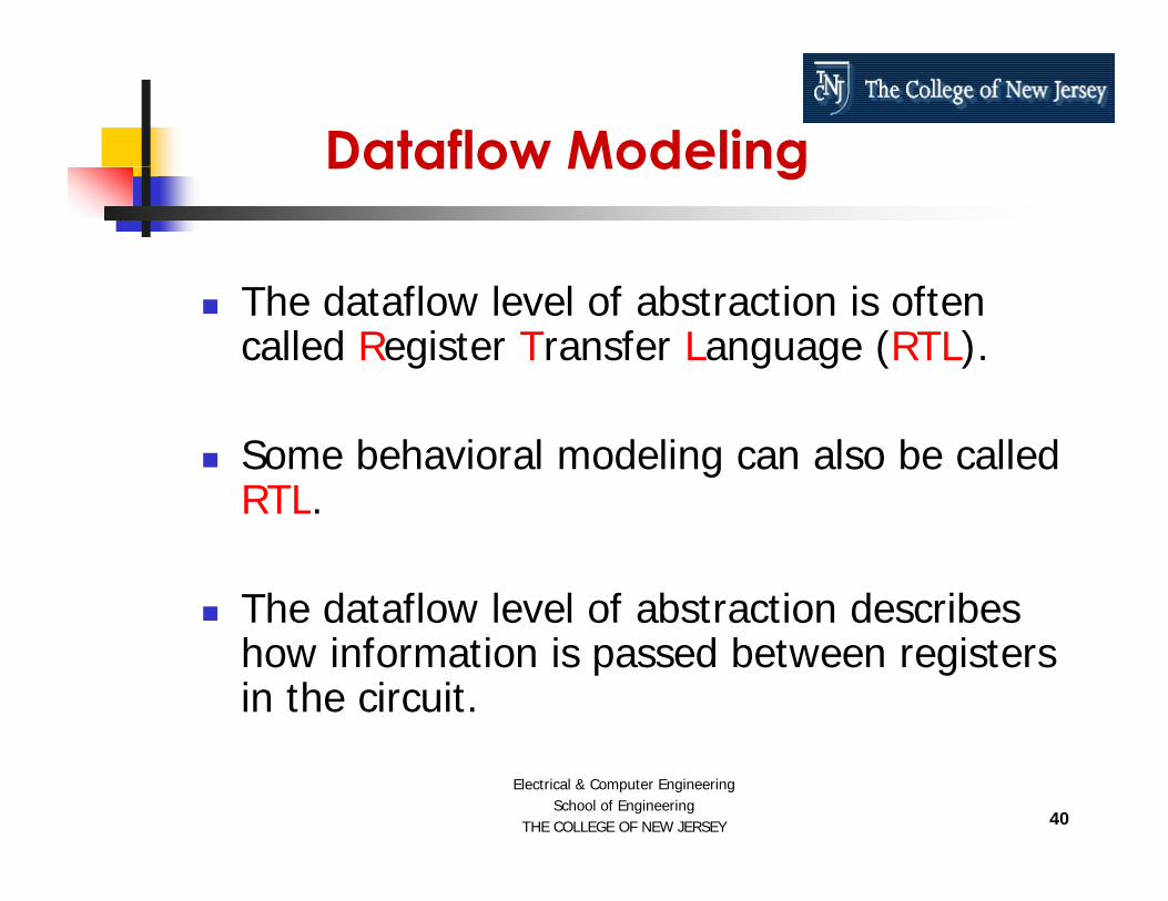
Dataflow ModelingDataflow Modeling
The dataflow level of abstraction is often called Register Transfer Language (RTL).
Some behavioral modeling can also be called RTLRTL.
The dataflow level of abstraction describesThe dataflow level of abstraction describes how information is passed between registers in the circuit.
40
Electrical & Computer EngineeringSchool of Engineering
THE COLLEGE OF NEW JERSEY

Concurrent and Sequential VerilogConcurrent and Sequential Verilog
Verilog Allows Both Concurrent and Sequential Statements to Be Entered.
The Difference Between Concurrent and The Difference Between Concurrent and Sequential Statements Must Be Known for Effective Use of the Languagefor Effective Use of the Language.
41
Electrical & Computer EngineeringSchool of Engineering
THE COLLEGE OF NEW JERSEY

Concurrent VerilogConcurrent Verilog
All Statements in the Concurrent Area Are Executed at the Same Time.
There Is No Significance to the Order in There Is No Significance to the Order in Which Concurrent Statements Occur.
42
Electrical & Computer EngineeringSchool of Engineering
THE COLLEGE OF NEW JERSEY

Concurrent VerilogConcurrent Verilog
:
Statement
St t tStatement
StatementStatement
:
43
Electrical & Computer EngineeringSchool of Engineering
THE COLLEGE OF NEW JERSEY

Example of Concurrent VerilogExample of Concurrent Verilog
Full Adder
aSum
bC out
Full-Adder_
C_in
44
Electrical & Computer EngineeringSchool of Engineering
THE COLLEGE OF NEW JERSEY
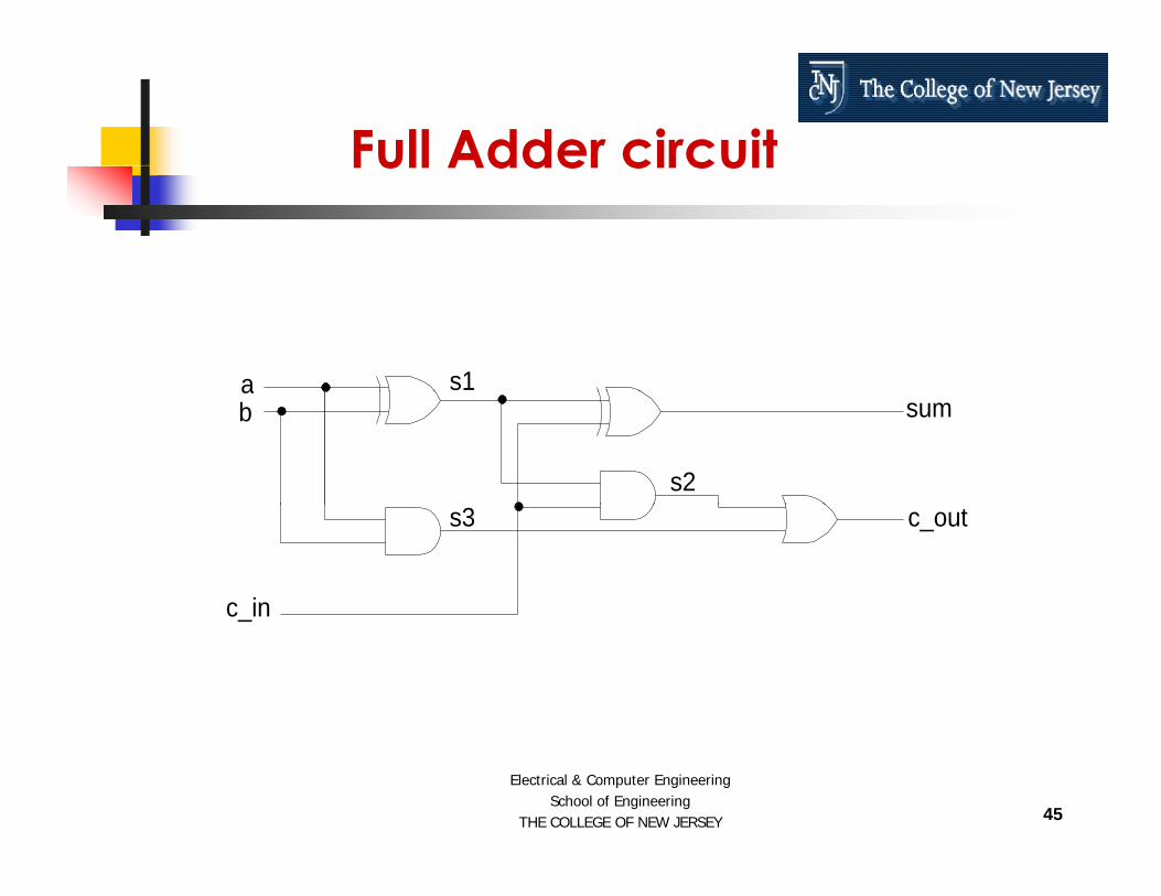
Full Adder circuitFull Adder circuit
a s1ab sum
s2
c in
c_outs3
_
45
Electrical & Computer EngineeringSchool of Engineering
THE COLLEGE OF NEW JERSEY

Verilog code for Full AdderVerilog code for Full Adder
// Full Adder Using Signal Assignment Instructionsmodule full_adder (a, b, c_in, sum, c_out);
input a, b, c_in;output sum, c_out;
wire s1, s2, s3;
assign s1 = a ^ b;assign s2 = s1 & c_in;assign s3 = a & b;assign sum = s1 ^ c_in;assign c_out = s2 | s3;
46
Electrical & Computer EngineeringSchool of Engineering
THE COLLEGE OF NEW JERSEY
endmodule

Verilog code for Full AdderVerilog code for Full Adder
The assign expressions are all concurrent signal assignment g gstatements. All the statements are executed at the same time.
assign s1 = a ^ b;assign s2 = s1 & c_in;
i 3 & bassign s3 = a & b;assign sum = s1 ^ c_in;assign c out = s2 | s3;
47
Electrical & Computer EngineeringSchool of Engineering
THE COLLEGE OF NEW JERSEY
ass g c_out s | s3;

Verilog code for Full AdderVerilog code for Full Adder
The simulator evaluates all the assignexpressions, and then applies the
lt t th i lresults to the signals.
Once the simulator has applied the results it waits for one of the signal to h d it l t ll thchange and it reevaluates all the
expressions again.
48
Electrical & Computer EngineeringSchool of Engineering
THE COLLEGE OF NEW JERSEY

Verilog code for Full AdderVerilog code for Full Adder
This cycle will continue until the simulation is completed.
This is called “event driven simulation” This is called event driven simulation .
I i i ll ffi i h It is more computationally efficient than time driven simulation.
49
Electrical & Computer EngineeringSchool of Engineering
THE COLLEGE OF NEW JERSEY

WiresWires
In the full_adder Verilog code we came across “wire”.
So what are “wires”? So what are wires ?
Wires Are Used to Carry Data From Place to Place in a Verilog Design Description.Verilog Design Description.
Wires in Verilog Are Similar to Wires in a Schematic.
Wires are internal to a module.
50
Electrical & Computer EngineeringSchool of Engineering
THE COLLEGE OF NEW JERSEY
Sequential VerilogSequential Verilog
Sequential Statements Are Executed One After the Other in the Order That They Appear.
Example of Sequential Statement: AlwaysAlways.
51
Electrical & Computer EngineeringSchool of Engineering
THE COLLEGE OF NEW JERSEY

Sequential Verilog
Begin
Sequential Verilog
Begin
St t tStatement
StatementStatement
StatementStatement
End
52
Electrical & Computer EngineeringSchool of Engineering
THE COLLEGE OF NEW JERSEY
End

Always ConstructAlways Construct
The Always construct is the primary means to describe sequential operations.
Always starts with the keyword always, thenb d d h h k d dbegin, and ends with the keyword end.
The whole always construct itself is treated as a concurrent statement.
53
Electrical & Computer EngineeringSchool of Engineering
THE COLLEGE OF NEW JERSEY

Always StatementAlways Statement
The always construct consists of three parts
Sensitivity List Sensitivity List Declaration Part Statement Part Statement Part
54
Electrical & Computer EngineeringSchool of Engineering
THE COLLEGE OF NEW JERSEY

Syntax of Always Statement
module module name ( … ports … );
Syntax of Always Statement
module module_name ( … ports … );:
always @ (sensitivity_list)begin : block_name
local_declaration;……sequential statement;sequential statement;……
endendmodule
55
Electrical & Computer EngineeringSchool of Engineering
THE COLLEGE OF NEW JERSEY
endmodule

Always Example
module nand2 (a, b, c);
Always Example
( , , );input a, b;output c;
reg c;
always @ (a or b)begin : nand2 always blockbegin : nand2_always_block
reg temp;temp = ~(a & b);if (temp == 1’b1) #5 c = temp;if (temp == 1 b1) #5 c = temp;else if (temp == 1’b0) #6 c = temp;
endendmodule
56
Electrical & Computer EngineeringSchool of Engineering
THE COLLEGE OF NEW JERSEY
endmodule
Example DescriptionExample Description
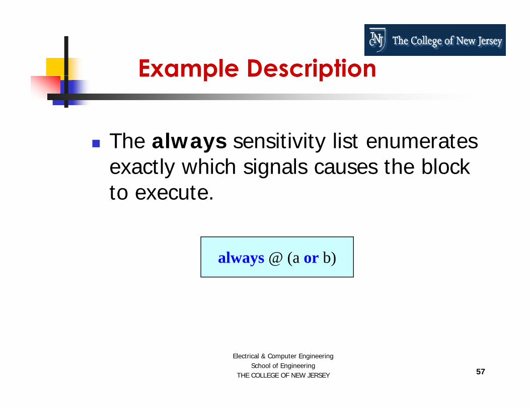
The always sensitivity list enumerates exactly which signals causes the block to execute.
always @ (a or b)
57
Electrical & Computer EngineeringSchool of Engineering
THE COLLEGE OF NEW JERSEY

Example DescriptionExample Description
The declarative part is used to declare local variables or constants that can be used in the block.
reg temp;
58
Electrical & Computer EngineeringSchool of Engineering
THE COLLEGE OF NEW JERSEY

Example DescriptionExample Description
Variables are temporary storage areas similar to variables in software programming languages.
reg temp;
59
Electrical & Computer EngineeringSchool of Engineering
THE COLLEGE OF NEW JERSEY

Use of Sequential StatementsUse of Sequential Statements
Sequential Statements Exist Inside the Always Statements As Well As in Sub Programs.
The Sequential Statements Are:if case forever repeatif case forever repeatwhile for wait fork/join
60
Electrical & Computer EngineeringSchool of Engineering
THE COLLEGE OF NEW JERSEY

if Statementsif Statements
The IF statement starts with the keyword if and ends with the keyword end.
if (x < 10) begina = b;
endend
61
Electrical & Computer EngineeringSchool of Engineering
THE COLLEGE OF NEW JERSEY

if Statementsif Statements
There are also two optional clausesif (day == Sunday) begin
else if clause else clause
if (day == Sunday) beginweekend = true;
end (d d ) else clause else if (day == Saturday) begin
weekend = true; end else begin
weekday = true; end
62
Electrical & Computer EngineeringSchool of Engineering
THE COLLEGE OF NEW JERSEY
end

if Statementsif Statements
The if statement can have multiple else if statement parts but only one elsestatement part.
63
Electrical & Computer EngineeringSchool of Engineering
THE COLLEGE OF NEW JERSEY

Case StatementCase Statement
The Case statement is used whenever a single expression value can be used to
l t b t b f tiselect between a number of actions.
A Case statement consists of the keyword case followed by an operator
i d d d ithexpression, and ended with an endcase keyword.
64
Electrical & Computer EngineeringSchool of Engineering
THE COLLEGE OF NEW JERSEY

Case StatementCase Statement
The expression will either return a value that matches one of the choices in a statement part or match a defaultclause.
65
Electrical & Computer EngineeringSchool of Engineering
THE COLLEGE OF NEW JERSEY

Case Statement Example
[1 0] bit
Case Statement Example
reg [1:0] bit_vec;……case bit_vec
2’b00 :2 b00 :return = 0;2’b01 :return = 1;return 1;2’b10 :return = 2;2’b11 :return = 3;
endcase
66
Electrical & Computer EngineeringSchool of Engineering
THE COLLEGE OF NEW JERSEY
Loop StatementsLoop Statements
The loop statement is used whenever an operation needs to be repeated.
Loop statements are implemented in three waysways
repeat condition loop statementp p while condition loop statement for condition loop statement
67
Electrical & Computer EngineeringSchool of Engineering
THE COLLEGE OF NEW JERSEY

Loop Statements (repeat)Loop Statements (repeat)
The repeat condition Loop statement will loop as many times as the condition expression.
repeat (flag) beginday = get_next_day (day);y g _ _ y ( y)
end
68
Electrical & Computer EngineeringSchool of Engineering
THE COLLEGE OF NEW JERSEY

Loop Statements (while)Loop Statements (while)
The while condition Loop statement will loop as long as the condition expression is TRUE.
while (day == weekday) beginday = get_next_day (day);y g _ _ y ( y)
end
69
Electrical & Computer EngineeringSchool of Engineering
THE COLLEGE OF NEW JERSEY

Loop Statements (for loop)Loop Statements (for loop)
for (i = 1; i <= 10; i = i + 1) begini_squared[i] = i*i;
endend
This loop will execute 10 times pwhenever execution begins and its function is to calculate squares from 1 qto 10 and insert them into i_squared memory.
70
Electrical & Computer EngineeringSchool of Engineering
THE COLLEGE OF NEW JERSEY
y

Wait StatementWait Statement
The wait statement allows to suspend the sequential execution based on a conditional expression.
wait until an expression is true.
wait (conditional expression)
71
Electrical & Computer EngineeringSchool of Engineering
THE COLLEGE OF NEW JERSEY

Wait StatementWait Statement
The wait conditional expression clause pwill suspend execution of the process until the expression returns a true pvalue.
initialbegin
wait (!oe)wait (!oe) o = q;
end
72
Electrical & Computer EngineeringSchool of Engineering
THE COLLEGE OF NEW JERSEY

Structural VerilogStructural Verilog
Structural-level design methods can be useful for managing the complexity of a large design description.
Structure level of abstraction is used to combine multiple components to form acombine multiple components to form a larger circuit.
73
Electrical & Computer EngineeringSchool of Engineering
THE COLLEGE OF NEW JERSEY

Structural VerilogStructural Verilog
Structural Verilog Descriptions Are Quite Similar in Format to Schematic Netlists.
Larger Circuits Can Be Constructed From Smaller Building BlocksFrom Smaller Building Blocks.
74
Electrical & Computer EngineeringSchool of Engineering
THE COLLEGE OF NEW JERSEY

Example of Structural VerilogExample of Structural Verilog
Let us consider an ALU with An OR gateAn OR gate An XOR gate
A Half Adder A Half Adder A Full Adder A Multiplexer
75
Electrical & Computer EngineeringSchool of Engineering
THE COLLEGE OF NEW JERSEY

Example of Structural VerilogVerilog
ALU
OR gate
XORgate
Half Adder
FullAdder Mux
76
Electrical & Computer EngineeringSchool of Engineering
THE COLLEGE OF NEW JERSEY

ALU – Block Diagram
s1 s0
ALU Block Diagram
ab
s1 s0
b
4 to 1 Z
C_out
4 to 1muxhalf
adder
c_in
fulladder
77
Electrical & Computer EngineeringSchool of Engineering
THE COLLEGE OF NEW JERSEY

ALU – Function TableALU Function Table
S1 S0 Z C outS1 S0 Z C_out0 0 a or b 00 1 a xor b 00 1 a xor b 01 0 ha_sum ha_c_out1 1 fa sum fa c out
a b
s1 s0
1 1 fa_sum fa_c_out
Z
C_out
4 to 1muxhalf
adder
full
78
Electrical & Computer EngineeringSchool of Engineering
THE COLLEGE OF NEW JERSEY
c_in
fulladder

Verilog code for OR gateVerilog code for OR gate
module t or (a b ored);module t_or (a, b, ored);input a, b;output ored;p ;
assign ored = a | b;endmodule
79
Electrical & Computer EngineeringSchool of Engineering
THE COLLEGE OF NEW JERSEY

Verilog code for XORVerilog code for XOR
d l t ( b d)module t_xor (a, b, xored);input a, b;output xored;
assign xored = a ^ b;d d lendmodule
80
Electrical & Computer EngineeringSchool of Engineering
THE COLLEGE OF NEW JERSEY

Verilog Code for half adderVerilog Code for half_adder
// Half Addermodule half_adder (a, b, sum, c_out);
input a, b; // declaring I/O portsoutput sum, c_out;
assign sum = a ^ b;
sum
carry
a
b
g ;assign c_out = a & b;
endmodule
Figure 1-1 Half adder circuit
81
Electrical & Computer EngineeringSchool of Engineering
THE COLLEGE OF NEW JERSEY
endmodule

Full Adder circuitFull Adder circuit
a s1ab sum
s2
c in
c_outs3
_
82
Electrical & Computer EngineeringSchool of Engineering
THE COLLEGE OF NEW JERSEY

Verilog code for full adderVerilog code for full_adder
// F ll Add// Full Addermodule full_adder (a, b, c_in, sum, c_out);
input a, b, c_in;output sum, c_out;
wire s1, s2, s3;
assign s1 = a ^ b;i 2 i & 1assign s2 = c_in & s1;
assign s3 = a & b;assign sum = a ^ b;assign c_out = s2 | s3;
d d lendmodule
// Using Signal Assignment Instructions
83
Electrical & Computer EngineeringSchool of Engineering
THE COLLEGE OF NEW JERSEY

Main Code for ALUMain Code for ALU
module alu (a b c in s0 s1 z c out);module alu (a, b, c_in, s0, s1, z, c_out);input a, b, c_in, s0, s1;output z, c_out;
reg z, c_out;
wire ored, xored, ha_sum, ha_c_out, fa_sum, fa_c_out;
t_or a1 (.a(a), .b(b), .ored(ored));t_xor x1 (.a(a), .b(b), .xored(xored));half_adder h1 (.a(a), .b(b), .sum(ha_sum),
(h )).c_out(ha_c_out));full_adder f1 (.a(a), .b(b), .c_in(c_in), .sum(fa_sum),
.c_out(fa_c_out));
84
Electrical & Computer EngineeringSchool of Engineering
THE COLLEGE OF NEW JERSEY

Main Code for ALU Cont….
always @ (a or b or c_in or s0 or s1) begin
Main Code for ALU Cont….
y ( _ ) gif (s1 == 1’b0 && s0 == 1’b0) begin
z = ored;c_out = 1’b0;
endif (s1 == 1’b0 && s0 == 1’b1) beginif (s1 == 1 b0 && s0 == 1 b1) begin
z = xored;c_out = 1’b0;
endif (s1 == 1’b1 && s0 == 1’b0) begin
z = ha_sum;c_out = ha_c_out;
endif (s1 == 1’b1 && s0 = 1’b1) begin
z = fa sum;z fa_sum;c_out = fa_c_out;
endend
endmodule
85
Electrical & Computer EngineeringSchool of Engineering
THE COLLEGE OF NEW JERSEY

CONTROL AND DATA PATH ORGANIZATION
86
Electrical & Computer EngineeringSchool of Engineering
THE COLLEGE OF NEW JERSEY

Control and Data Path OrganizationControl and Data Path Organization
Most complex digital circuits can be broken up into two parts: Control Data Path
87
Electrical & Computer EngineeringSchool of Engineering
THE COLLEGE OF NEW JERSEY

Control and Data Path OrganizationControl and Data Path Organization
DATACONTROLINPUTS
CONTROLPROCESSING
DATAPROCESSING
CONTROL
PROCESSINGBLOCK
PROCESSINGBLOCK
OBSERVATION
STATUS
88
Electrical & Computer EngineeringSchool of Engineering
THE COLLEGE OF NEW JERSEY

Finite State MachinesFinite State Machines
Two Classes of Finite State Machines (FSMs): Moore Machines Mealy Machinesy
89
Electrical & Computer EngineeringSchool of Engineering
THE COLLEGE OF NEW JERSEY

Moore Finite State Machines
Outputs depend only on the state
Moore Finite State Machines
State and Outputs Processing are combinational elements
State Vector is Sequential ElementsCLOCK
STATE OUTPUTSNEXT STATE OUTPUTSINPUTSSTATE
VECTOROUTPUTS
PROCESSINGNEXT STATEPROCESSING
OUTPUTS
90
Electrical & Computer EngineeringSchool of Engineering
THE COLLEGE OF NEW JERSEY
Mealy Finite State Machines
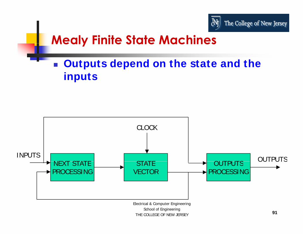
Outputs depend on the state and the i t
Mealy Finite State Machines
inputs
CLOCK
STATE OUTPUTSNEXT STATE OUTPUTSINPUTSSTATE
VECTOROUTPUTS
PROCESSINGNEXT STATEPROCESSING
OUTPUTS
91
Electrical & Computer EngineeringSchool of Engineering
THE COLLEGE OF NEW JERSEY

Verilog IMPLEMENTATION EXAMPLES – A Decimation Filter for
a Sigma-Delta Analog to Digital Converter
92
Electrical & Computer EngineeringSchool of Engineering
THE COLLEGE OF NEW JERSEY

2-Ch Σ-Δ Analog to Digital Converter2 Ch Σ Δ Analog to Digital Converter
RSTN
Clock GenerationG3 SYNC
G2G1
CLKPD1PD2PD3
RSTN
V1P
V1N x1, x2, x8, x16
PGA Integrators / Comparator
Digital Filter(Sinc3)
G0
CMP1
Digital Filter(Sinc3)
Digital Design
V21P
V21NPGA Integrators / Comparator
x1, x2, x8, x16
2nd Order Modulators
CMP2
Bandgap~ 1.25V
Analog Design
2 Order Modulators
93
Electrical & Computer EngineeringSchool of Engineering
THE COLLEGE OF NEW JERSEY
xx REF+ ADC

2nd Order Σ-Δ Modulator (block/algorithmic)(block/algorithmic)
z-1IN
OUT1 / CFA CX / CFBCIN
CY / CFBz-1
CREF
This can be modeled in Behavioral Verilog
94
Electrical & Computer EngineeringSchool of Engineering
THE COLLEGE OF NEW JERSEY

2nd Order Σ-Δ Modulator (circuit)(circuit)
VCMI
CFA CY
VCMI
CAZ
CIN CX CFBAZB
AZB
AZT1
T2
B1
B2
B2 S1
B1 S2
IN+
AMP1 AMP2
VCMI
CAZ
VCMI
CIN CX CFBAZBAZ
T2
T1
B2
B1 B2
B1 S2
S1
STRB
IN-
CFA CY
CREF B1
B2REF+
FL
“1”
“0”
VCMI
CREF
B2
B1REF-
FL
“0”
“1”
95
Electrical & Computer EngineeringSchool of Engineering
THE COLLEGE OF NEW JERSEY
This can also be modeled in Behavioral Verilog

Decimation Digital FilterDecimation Digital Filter
z-1 z-1 z-1
IN
fs fs / OSR
OUT
z-1 z-1 z-1
fs / OSR
96
Electrical & Computer EngineeringSchool of Engineering
THE COLLEGE OF NEW JERSEY

Decimation Digital FilterDecimation Digital Filter
Cubic sinc Bits of noise free accuracy for delta-Bits of noise free accuracy for delta
sigma ADC's: BITS = 3 * LOG(OSR) / LOG(2) + 2 BITS 3 LOG(OSR) / LOG(2) + 2 Assume OSR=32, then BITS=17, and set
BITS=16
97
Electrical & Computer EngineeringSchool of Engineering
THE COLLEGE OF NEW JERSEY

Decimation Digital FilterDecimation Digital Filter
First Filter Equations H1(z) = Y1(z)/X(z) = 1/(1 - 3 z-1 + 3 z-2 - z-3) y1(n) = x(n) + 3 y1(n-1) - 3 y1(n-2) + y1(n-3)
Second Filter Equations( ) ( )/ ( ) 1 2 3 H2(z) = Y(z)/X1(z) = 1 - 3 z-1 + 3 z-2 - z-3
y(n) = x1(n) - 3 x1(n-1) + 3 x1(n-2) - x1(n-3)Decimation (Retiming) Decimation (Retiming) x1(n)=y1(n/OSR) x (n)=y (n/32)
98
Electrical & Computer EngineeringSchool of Engineering
THE COLLEGE OF NEW JERSEY
x1(n)=y1(n/32)

What do we need for our design?What do we need for our design? y1(n) = x(n) + 3 y1(n-1) - 3 y1(n-2) + y1(n-3) y(n) = x1(n) - 3 x1(n-1) + 3 x1(n-2) - x1(n-3) x1(n)=y1(n/32)
Control On every x(n)
S02: Store x(n) in accumulator, count x(n) mod 32S03 A l 2 ( 1)
Data Path 16 bits Adder-Accumulator
S03: Accumulate 2 y1(n-1) S04: Accumulate y1(n-1) S05: Accumulate 1’s complement of 2 y1(n-2) S06: Accumulate 1’s complement of y1(n-2) S07: Accumulate 2 S08: Accumulate y1(n-3)
1’s complement Shift left by one (x 2) Store y1(n-1), y1(n-2), y1(n-3) Store x1(n-1), x1(n-2), x1(n-3)
Constants: 2 & 3 S08: Accumulate y1(n 3) S09: Update y registers
On every x1(n) (every 32nd y1(n)) S10: Accumulate 1’s complement of 2 x1(n-1) S11: Accumulate 1’s complement of x1(n-1) S12: Accumulate 2 x1(n-2)
Constants: 2 & 3
1( ) S13: Accumulate x1(n-2) S14: Accumulate 1’s complement of x1(n-3) S15: Accumulate 3, output result S16: Store y1(n-1) in accumulator S17: Update x registers
99
Electrical & Computer EngineeringSchool of Engineering
THE COLLEGE OF NEW JERSEY

Decimation Digital Filter ArchitectureDecimation Digital Filter Architecture
Ry1_n_1 Ry1_n_2 Ry1_n_3 Rx1_n_1 Rx1_n_2 Rx1_n_3
URy
S1 CONTROLLERURx
x2, PASS
1’S COMP., PASS, 2, 3
S2
S3
S1
S2
S3
xn
S3
S4
URyDATA-PATH
ACCUMULATOR
xnS4 URx
OSS
ISS
100
Electrical & Computer EngineeringSchool of Engineering
THE COLLEGE OF NEW JERSEY
OUTISS

Verilog code for Data PathVerilog code for Data_Path
// h// Data_Pathmodule Data_Path (CLK, reset, xn, URy, URx,
S2 S3 S4 S1S2, S3, S4, S1,OUTPUT);
input CLK, reset, xn, URy, URx, S2;input [1:0] S3, S4;input [2:0] S1;output [15:0] OUTPUT;
101
Electrical & Computer EngineeringSchool of Engineering
THE COLLEGE OF NEW JERSEY

Verilog code for Data Pathreg [15:0] Ry1_n_1, Ry1_n_2, Ry1_n_3;reg [15:0] Rx1_n_1, Rx1_n_2, Rx1_n_3;
[15 0] ACCUMULATOR
Verilog code for Data_Path3’b010 : T1 = Ry1_n_3;3’b011 : T1 = Rx1_n_1;3’b100 T1 R 1 2reg [15:0] ACCUMULATOR;
parameter my_zero = 16’b0000000000000000;
reg [15:0] T1, T2, T3, T4, T5;reg my_msb;
3’b100 : T1 = Rx1_n_2;3’b101 : T1 = Rx1_n_3;
endcasecase (S2)
1’b0 :my_msb = T1[15];T2 = T1 << 1;
assign OUTPUT = ACCUMULATOR;
always @ (posedge CLK or reset) beginif (reset == 1’b1) begin
Ry1_n_1 = my_zero; Ry1_n_2 = my_zero; Ry1_n_3 = my_zero;Rx1_n_1 = my_zero; Rx1_n_2 = my_zero; Rx1_n_3 = my_zero;
T2 = T1 << 1;T3 = T2 & 16’b0111111111111111;T4 = T3 | {my_msb, 15’b000000000000000};
1’b1 : T4 = T1;endcasecase (S3)
2’b00 : T5 = ~T4;ACCUMULATOR = my_zero;
else if (CLK == 1’b1) beginif (URy == 1’b1) beginRy1_n_3 = Ry1_n_2; Ry1_n_2 = Ry1_n_1;Ry1_n_1 = ACCUMULATOR;
endif (URx == 1’b1) begin
2’b01 : T5 = T4;2’b10 : T5 = 16’b0000000000000010;2’b11 : T5 = 16’b0000000000000011;
endcasecase (S4)
2’b00 : ACCUMULATOR = {15’b000000000000000, xn};2’b01 : ACCUMULATOR = Ry1 n 1;if (URx == 1 b1) begin
Rx1_n_3 = Rx1_n_2; Rx1_n_2 = Rx1_n_1;Rx1_n_1 = ACCUMULATOR;
endcase (S1)
3’b000 : T1 = Ry1_n_1;3’b001 : T1 = Ry1_n_2;
2 b01 : ACCUMULATOR = Ry1_n_1;2’b10 : ACCUMULATOR = ACCUMULATOR + T5;
endcaseend
endendmodule
102
Electrical & Computer EngineeringSchool of Engineering
THE COLLEGE OF NEW JERSEY
y _ _ ;
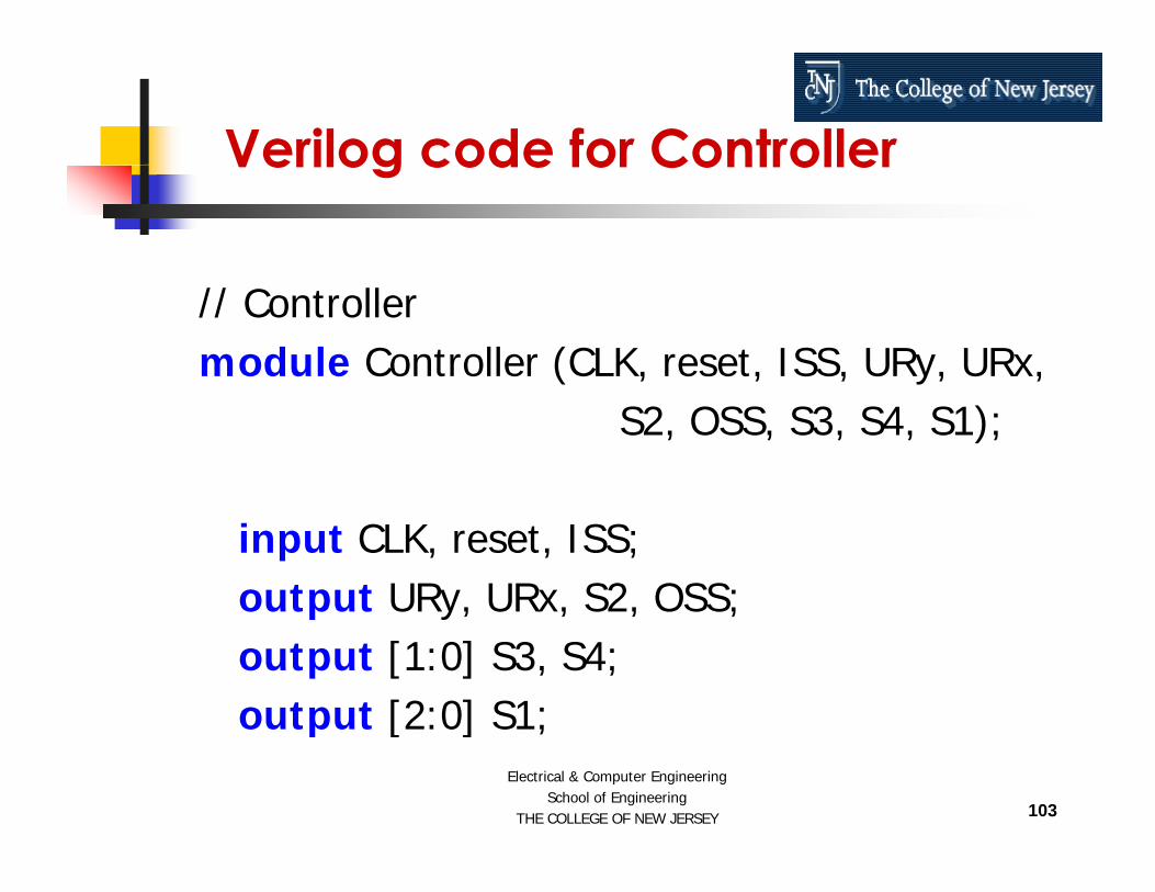
Verilog code for ControllerVerilog code for Controller
// Controllermodule Controller (CLK, reset, ISS, URy, URx,
S2, OSS, S3, S4, S1);
input CLK, reset, ISS;output URy, URx, S2, OSS;p y, , , ;output [1:0] S3, S4;output [2:0] S1;
103
Electrical & Computer EngineeringSchool of Engineering
THE COLLEGE OF NEW JERSEY
output [2:0] S1;

Verilog code for Controller
parameter S00 = 5’h00, S01 = 5’h01, S02 = 5’h02, S03 = 5’h03,S04 = 5’h04, S05 = 5’h05, S06 = 5’h06, S07 = 5’h07, S08 = 5’h08,
Verilog code for Controller
if (PRState == S03 || PRState == S05 ||S04 5 h04, S05 5 h05, S06 5 h06, S07 5 h07, S08 5 h08,S09 = 5’h09, S10 = 5’h0A, S11 = 5’h0B, S12 = 5’h0C, S13 = 5’h0D,S14 = 5’h0E, S15 = 5’h0F, S16 = 5’h10, S17 = 5’h11;
reg URy, URx, S2, OSS;reg [1:0] S3, S4;reg [2:0] S1;
PRState == S10 || PRState == S12) S2 = 1’b0;else S2 = 1’b1;if (PRState == S05 || PRState == S06 ||
PRState == S10 || PRState == S11 ||PRState == S14) S3 = 2’b00;
else if (PRState S07) S3 2’b10;reg [4:0] PRState, NXState;
reg [4:0] Counter;
always @ (PRState) beginif (PRState == S09) URy = 1’b1;
else if (PRState == S07) S3 = 2’b10;else if (PRState == S15) S3 = 2’b11;else S3 = 2’b01;if (PRState == S02) S4 = 2’b00;else if (PRState == S16) S4 = 2’b01;else S4 = 2’b10;if (PRState == S09) URy = 1 b1;
else URy = 1’b0;if (PRState == S17) URx = 1’b1;else URx = 1’b0;if (PRState == S05 || PRState == S06) S1 = 3’b001;else if (PRState == S08) S1 = 3’b010;else if (PRState == S10 || PRState == S11) S1 = 3’b011;
else S4 2 b10;if (PRState == S15) OSS = 1’b1;else OSS = 1’b0;
end
else if (PRState == S12 || PRState == S13) S1 = 3’b100;else if (PRState == S14) S1 = 3’b101;else S1 = 3’b000;
104
Electrical & Computer EngineeringSchool of Engineering
THE COLLEGE OF NEW JERSEY

Verilog code for Controlleralways @ (posedge CLK or reset) begin
if (reset == 1’b1) begin
Verilog code for ControllerS07 : NXState = S08;S08 : NXState = S09;if (reset == 1 b1) begin
PRState = S00;Counter = 5’b00000;
endelse begin
PRSt t NXSt t
S08 : NXState = S09;S09 : if (Counter == 5’b00000) NXState = S10;
else NXState = S01;S10 : NXState = S11;S11 : NXState = S12;S12 NXSt t S13PRState = NXState;
if (Counter == 5’b11111) Counter = 5’b00000;else Counter = Counter + 5’b00001;
endend
S12 : NXState = S13;S13 : NXState = S14;S14 : NXState = S15;S15 : NXState = S16;S16 : NXState = S17
always @ (PRState or ISS) begincase (PRState)
S00 : if (ISS == 1’b1) NXState = S02;S01 : if (ISS == 1’b1) NXState = S02;S02 : NXState S03;
S17 : NXState = S01;endcase
endendmodule
S02 : NXState = S03;S03 : NXState = S04;S04 : NXState = S05;S05 : NXState = S06;S06 : NXState = S07;
105
Electrical & Computer EngineeringSchool of Engineering
THE COLLEGE OF NEW JERSEY
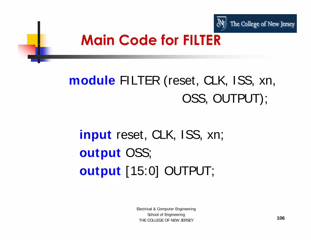
Main Code for FILTERMain Code for FILTER
module FILTER (reset, CLK, ISS, xn,OSS, OUTPUT);, );
input reset CLK ISS xn;input reset, CLK, ISS, xn;output OSS;output [15:0] OUTPUT;
106
Electrical & Computer EngineeringSchool of Engineering
THE COLLEGE OF NEW JERSEY

Main Code for FILTER Cont…wire URy, URx, S2;wire [1:0] S3 S4;
Main Code for FILTER Cont…
wire [1:0] S3, S4;wire [2:0] S1;
Controller c ( CLK(CLK) reset(reset)Controller c (.CLK(CLK), .reset(reset),.ISS(ISS), .URy(URy), .URx(URx), .S2(S2),.OSS(OSS), .S3(S3), .S4(S4), .S1(S1));
Data_Path dp (.CLK(CLK), .reset(reset),_ p ( ( ), ( ),.xn(xn), .URy(URy), .URx(URx), .S2(S2),.S3(S3), .S4(S4), .S1(S1), .OUTPUT(OUTPUT));
endmodule
107
Electrical & Computer EngineeringSchool of Engineering
THE COLLEGE OF NEW JERSEY

ConclusionsConclusions
108
Electrical & Computer EngineeringSchool of Engineering
THE COLLEGE OF NEW JERSEY
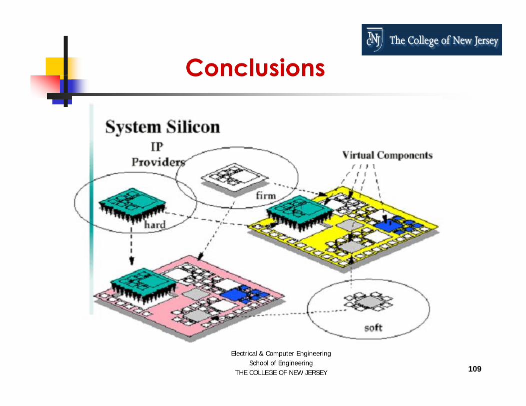
ConclusionsConclusions
109
Electrical & Computer EngineeringSchool of Engineering
THE COLLEGE OF NEW JERSEY

Thanks……Thanks……
h d @t j [email protected]
http://www tcnj edu/~hernande/110
Electrical & Computer EngineeringSchool of Engineering
THE COLLEGE OF NEW JERSEY
http://www.tcnj.edu/ hernande/


![“A Verilog OverviewA Verilog Overview”hernande/Eng312/TCNJ_Verilog(R)_V...Comparator Verilog Source Code // Eight-bit Comparator module compare (A, B, EQ) input [7:0] A, B; output](https://static.fdocuments.net/doc/165x107/5f8b8feb76f68678470c12e5/aoea-verilog-overviewa-verilog-overviewa-hernandeeng312tcnjverilogrv.jpg)