
“A Verilog Overview” - TCNJhernande/ELEC471/TCNJ_Verilog(R)_V02.pdf · “A Verilog Overview...
110
“A Verilog Overview” by Orlando J. Hernandez, Ph.D. Electrical & Computer Engineering School of Engineering THE COLLEGE OF NEW JERSEY Fall Semester, 2003
Transcript of “A Verilog Overview” - TCNJhernande/ELEC471/TCNJ_Verilog(R)_V02.pdf · “A Verilog Overview...

“A Verilog Overview”by
Orlando J. Hernandez, Ph.D.Electrical & Computer Engineering
School of EngineeringTHE COLLEGE OF NEW JERSEY
Fall Semester, 2003

Fall Semester, 2003
Electrical & Computer EngineeringSchool of Engineering
THE COLLEGE OF NEW JERSEY 2
Presentation Overview
Introduction to Verilog – Part IIntroduction to Verilog – Part II
AND, OR, HALF ADDER, FULL ADDERIntroduction to Verilog – Part III
ALU DesignControl and Data Path Organization
Finite State Machines, Digital FilterQ&A Sessions

Fall Semester, 2003
Electrical & Computer EngineeringSchool of Engineering
THE COLLEGE OF NEW JERSEY 3
INTRODUCTION TO VerilogPART I

Fall Semester, 2003
Electrical & Computer EngineeringSchool of Engineering
THE COLLEGE OF NEW JERSEY 4
Design Automation
Need To Keep With Rapid Changes, Electronic Products Have To Be Designed Extremely QuicklyElectronic Design Automation (EDA)
Design EntrySimulationSynthesisDesign Validation & Test

Fall Semester, 2003
Electrical & Computer EngineeringSchool of Engineering
THE COLLEGE OF NEW JERSEY 5
Design Automation. Cont…
Design EntrySchematic Capture
Q
QSET
CLR
S
R
Fall Semester, 2003
Electrical & Computer EngineeringSchool of Engineering
THE COLLEGE OF NEW JERSEY 6
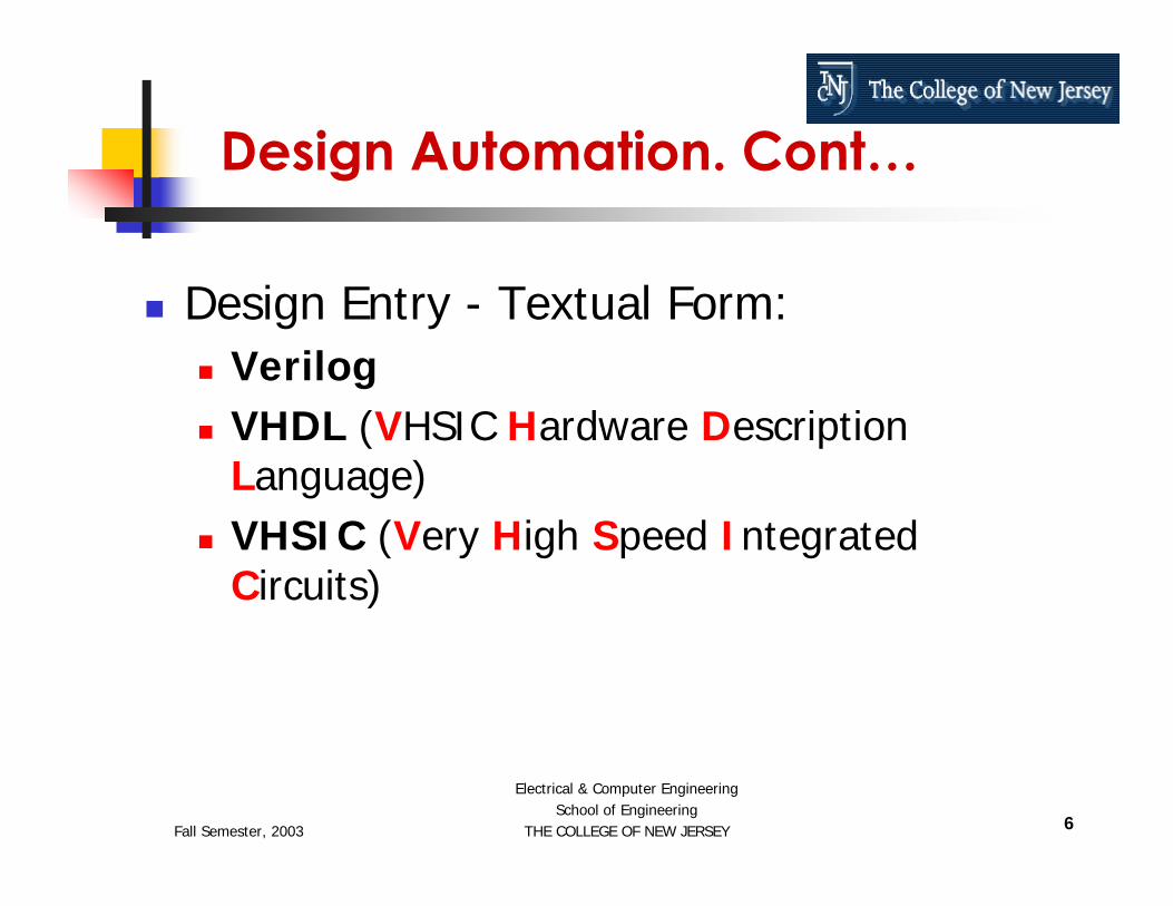
Design Automation. Cont…
Design Entry - Textual Form: VerilogVHDL (VHSIC Hardware Description Language) VHSIC (Very High Speed Integrated Circuits)

Fall Semester, 2003
Electrical & Computer EngineeringSchool of Engineering
THE COLLEGE OF NEW JERSEY 7
Design Automation. Cont…
Design Entry - Textual Form:
module and_2 (X, Y, Z);input X, Y;output Z;
assign Z = X & Y;endmodule

Fall Semester, 2003
Electrical & Computer EngineeringSchool of Engineering
THE COLLEGE OF NEW JERSEY 8
Verilog Is an Industry Standard Language to Describe Hardware From the Abstract to Concrete Level.
Introduction To Verilog

Fall Semester, 2003
Electrical & Computer EngineeringSchool of Engineering
THE COLLEGE OF NEW JERSEY 9
BRIEF HISTORY OF Verilog
Began as a proprietary HDL promoted by Cadence Design Systems.
Cadence transferred control of Verilog to a consortium of companies and universities known as Open Verilog International (OVI).
Verilog is an IEEE Standard (IEEE Standard 1364-1995).
Verilog continues to be extended and upgraded (IEEE Standard 1364-2000, System Verilog).

Fall Semester, 2003
Electrical & Computer EngineeringSchool of Engineering
THE COLLEGE OF NEW JERSEY 10
MOTIVATION
Need a Method to Quickly Design, Implement, Test and Document Increasingly Complex Digital Systems.
Schematic and Boolean Equations Inadequate for Million-Gate ICs.
Design Portability

Fall Semester, 2003
Electrical & Computer EngineeringSchool of Engineering
THE COLLEGE OF NEW JERSEY 11
What is Verilog?
A Design entry languageA Simulation modeling language.A Verification language.A Standard language.As simple or complex as required.

Fall Semester, 2003
Electrical & Computer EngineeringSchool of Engineering
THE COLLEGE OF NEW JERSEY 12
For Design Specification (“Specify”)
For Design Entry (“Capture”)
For Design Simulation (“Verify”)
For Design Documentation (“Formalize”)
As an Alternate to Schematics
How is Verilog Used?
Specify
Capture
Verify
Formalize
Implement

Fall Semester, 2003
Electrical & Computer EngineeringSchool of Engineering
THE COLLEGE OF NEW JERSEY 13
Design Entry
Synthesis Functional Simulation
Device Mapping Timing Simulation
Device
Test Development
Design Process (e. g. for FPGAs)
Verilog Can Be Used for Both Design and Test Development

Fall Semester, 2003
Electrical & Computer EngineeringSchool of Engineering
THE COLLEGE OF NEW JERSEY 14
Verilog is highly beneficial to use as a structured, top down approach to design.Verilog makes it easy to build, use, and reuse libraries of circuit elements.Verilog can greatly improve your chances of moving into more advanced tools and design flows.
When Should Verilog Be Used?

Fall Semester, 2003
Electrical & Computer EngineeringSchool of Engineering
THE COLLEGE OF NEW JERSEY 15
Advantages of Verilog
The Ability to Code the Behavior and to Synthesize an Actual Circuit.
Power and Flexibility
Device (specific FPGA) Independent Design
Technology (specific silicon process) Independent Design

Fall Semester, 2003
Electrical & Computer EngineeringSchool of Engineering
THE COLLEGE OF NEW JERSEY 16
Portability Among Tools and Devices
Fast Switch Level Simulations
Quick Time to Market and Low Cost
Industry Standard
Advantages of Verilog Cont…

Fall Semester, 2003
Electrical & Computer EngineeringSchool of Engineering
THE COLLEGE OF NEW JERSEY 17
Getting Started with Verilog
Its Easy To Get Started With Verilog, But It Can Be Difficult To Master It.To Begin With, A Subset of The Language Can Be Learned To Write Useful Models.Later, More Complex Features Can Be Learned To Implement Complex Circuits, Libraries, And APIs.

Fall Semester, 2003
Electrical & Computer EngineeringSchool of Engineering
THE COLLEGE OF NEW JERSEY 18
A First look at Verilog
Lets start with a simple Combinational circuit: an 8-bit Comparator.

Fall Semester, 2003
Electrical & Computer EngineeringSchool of Engineering
THE COLLEGE OF NEW JERSEY 19
An 8 Bit Comparator
Comparator Specifications:Two 8-bit inputs1-bit Output Output is 1 if the inputs match or 0 if they differ.

Fall Semester, 2003
Electrical & Computer EngineeringSchool of Engineering
THE COLLEGE OF NEW JERSEY 20
0 1 2 3 4 5 6 7A 1 0 1 1 0 0 1 1B 1 0 1 1 0 0 1 1
An 8 Bit Comparator
Comparator
A[8]
EQB[8]

Fall Semester, 2003
Electrical & Computer EngineeringSchool of Engineering
THE COLLEGE OF NEW JERSEY 21
// Eight-bit Comparatormodule compare (A, B, EQ)
input [7:0] A, B;output EQ;
assign EQ = (A == B);endmodule
Define the inputs and outputs - the ports of the circuitDefine the function of the circuit
Comparator Verilog Source Code

Fall Semester, 2003
Electrical & Computer EngineeringSchool of Engineering
THE COLLEGE OF NEW JERSEY 22
What is a module
Every Verilog design description has at least one module construct.
A large design has many modules and are connected to form the complete circuit.
The module port declarations describe the circuit as it appears from “outside”- from perspective of its input and output interfaces.

Fall Semester, 2003
Electrical & Computer EngineeringSchool of Engineering
THE COLLEGE OF NEW JERSEY 23
module compare (A, B, EQ)input [7:0] A, B;output EQ;
::
The module and port declarations includes a name, compare, and port direction statements defining all the inputs and outputs of the module.
The Rest of the module Describes the Actual Function.
What is a module?

Fall Semester, 2003
Electrical & Computer EngineeringSchool of Engineering
THE COLLEGE OF NEW JERSEY 24
What is a module?
::
assign EQ = (A == B);endmodule
Before the keyword endmodule is found the actual functional description of the comparator.

Fall Semester, 2003
Electrical & Computer EngineeringSchool of Engineering
THE COLLEGE OF NEW JERSEY 25
Data Types
Verilog’s high level data types allow data to be represented in much the same way as in high-level programming languages.
A data type is an abstract representation of stored data.

Fall Semester, 2003
Electrical & Computer EngineeringSchool of Engineering
THE COLLEGE OF NEW JERSEY 26
Data Types
These data types might represent individual wires in a circuit, or a collection of wires.

Fall Semester, 2003
Electrical & Computer EngineeringSchool of Engineering
THE COLLEGE OF NEW JERSEY 27
Data Types
Basic Data TypesNets
wire, wand, tri, worContinuously drivenGets new value when driver changesLHS of continuous assignment
tri [15:0] data;// unconditional
assign data[15:0] = data_in;// conditional
assign data[15:0] = enable ? data_in : 16’bz;
RegistersRegRepresents storageAlways stores last assigned valueLHS of an assignment in a procedural block
reg signal;@(posedge clock) signal = 1’b1;
// possitive edge@(reset) signal = 1’b0; // event (both edges)

Fall Semester, 2003
Electrical & Computer EngineeringSchool of Engineering
THE COLLEGE OF NEW JERSEY 28
Data Type Values ExamplesBitArray of bitsBooleanIntegerRealTime
CharacterString
'1' , '0' , 'x' , 'z'"101001"Use Bit-2, -1, 0, 1, 2, 31.0, -1.0E5‘timescale 1ns/1ps
Use 8-bit registerUse register of length 8 x the # of characters
Q = 1’b1;Data[5:0] = 6’b101001;EQ = 1’b1; // TrueC = c+2;V1 = V2/5.3;
#6 Q = 1’b1;
Some Data Types
Register Single or array of bits

Fall Semester, 2003
Electrical & Computer EngineeringSchool of Engineering
THE COLLEGE OF NEW JERSEY 29
Design Units
Design units are a concept that provide advanced configuration management capabilities.
Design units are modules of Verilog that can be compiled separately and stored in a library.

Fall Semester, 2003
Electrical & Computer EngineeringSchool of Engineering
THE COLLEGE OF NEW JERSEY 30
Library Design unit
A Library is a collection of commonly used modules to be used globally among different design units.
Library is identified with compiler/simulator command line switches.

Fall Semester, 2003
Electrical & Computer EngineeringSchool of Engineering
THE COLLEGE OF NEW JERSEY 31
Levels of Abstraction (Styles)
Verilog supports many possible styles of design description.
These styles differ primarily in how closely they relate to the underlying hardware.

Fall Semester, 2003
Electrical & Computer EngineeringSchool of Engineering
THE COLLEGE OF NEW JERSEY 32
Levels of Abstraction refers to how far your design description is from an actual hardware realization.The three main levels of abstraction are:
BehaviorDataflowStructure
Levels of Abstraction (Styles)

Fall Semester, 2003
Electrical & Computer EngineeringSchool of Engineering
THE COLLEGE OF NEW JERSEY 33
Behavior Dataflow Structure
Performance Specification Test Benches
Sequential Description State Machines
Register Transfers Selected Assignments Arithmetic Operation
Boolean Equations Hierarchy
Physical Information
Levels of Abstraction (Styles)

Fall Semester, 2003
Electrical & Computer EngineeringSchool of Engineering
THE COLLEGE OF NEW JERSEY 34
Behavioral Modeling
The Highest Level of Abstraction Supported in Verilog.
The Behavior Approach Describes the Actual Behavior of Signals Inside the Component.

Fall Semester, 2003
Electrical & Computer EngineeringSchool of Engineering
THE COLLEGE OF NEW JERSEY 35
The Concept of Time Is the Critical Distinction Between Behavioral Descriptions and Low Level Descriptions.
The Concept to Time May Be Expressed Precisely, With Actual Delays Between Related Events
Verilog Timing Issues

Fall Semester, 2003
Electrical & Computer EngineeringSchool of Engineering
THE COLLEGE OF NEW JERSEY 36
An Example of Behavioral Modeling: A half adder
carry
suma
b

Fall Semester, 2003
Electrical & Computer EngineeringSchool of Engineering
THE COLLEGE OF NEW JERSEY 37
half_adder
Half AdderInputs a, b : 1 bit each.Output Sum, Carry : 1 bit each.
sum
carry
a
b
Figure 1-1 Half adder circuit

Fall Semester, 2003
Electrical & Computer EngineeringSchool of Engineering
THE COLLEGE OF NEW JERSEY 38
Verilog Code for half_adder
// Half Addermodule half_adder (a, b, sum, carry);
input a, b;output sum, carry;
reg sum, carry;
always @ (a or b) beginsum = a ^ b;carry = a & b;
endendmodule

Fall Semester, 2003
Electrical & Computer EngineeringSchool of Engineering
THE COLLEGE OF NEW JERSEY 39
INTRODUCTION TO VerilogPART II

Fall Semester, 2003
Electrical & Computer EngineeringSchool of Engineering
THE COLLEGE OF NEW JERSEY 40
The dataflow level of abstraction is often called Register Transfer Language (RTL).
Some behavioral modeling can also be called RTL.
The dataflow level of abstraction describes how information is passed between registers in the circuit.
Dataflow Modeling

Fall Semester, 2003
Electrical & Computer EngineeringSchool of Engineering
THE COLLEGE OF NEW JERSEY 41
Concurrent and Sequential Verilog
Verilog Allows Both Concurrent and Sequential Statements to Be Entered.
The Difference Between Concurrent and Sequential Statements Must Be Known for Effective Use of the Language.

Fall Semester, 2003
Electrical & Computer EngineeringSchool of Engineering
THE COLLEGE OF NEW JERSEY 42
Concurrent Verilog
All Statements in the Concurrent Area Are Executed at the Same Time.
There Is No Significance to the Order in Which Concurrent Statements Occur.

Fall Semester, 2003
Electrical & Computer EngineeringSchool of Engineering
THE COLLEGE OF NEW JERSEY 43
:
Statement
Statement
Statement
:
Concurrent Verilog

Fall Semester, 2003
Electrical & Computer EngineeringSchool of Engineering
THE COLLEGE OF NEW JERSEY 44
Example of Concurrent Verilog
Full Adder
aSum
bC_out
C_in
Full-Adder

Fall Semester, 2003
Electrical & Computer EngineeringSchool of Engineering
THE COLLEGE OF NEW JERSEY 45
Full Adder circuit
ab
c_in
sum
c_out
s1
s3s2

Fall Semester, 2003
Electrical & Computer EngineeringSchool of Engineering
THE COLLEGE OF NEW JERSEY 46
Verilog code for Full Adder
// Full Adder Using Signal Assignment Instructionsmodule full_adder (a, b, c_in, sum, c_out);
input a, b, c_in;output sum, c_out;
wire s1, s2, s3;
assign s1 = a ^ b;assign s2 = s1 & c_in;assign s3 = a & b;assign sum = s1 ^ c_in;assign c_out = s2 | s3;
endmodule

Fall Semester, 2003
Electrical & Computer EngineeringSchool of Engineering
THE COLLEGE OF NEW JERSEY 47
Verilog code for Full Adder
The assign expressions are all concurrent signal assignment statements. All the statements are executed at the same time.
assign s1 = a ^ b;assign s2 = s1 & c_in;assign s3 = a & b;assign sum = s1 ^ c_in;assign c_out = s2 | s3;

Fall Semester, 2003
Electrical & Computer EngineeringSchool of Engineering
THE COLLEGE OF NEW JERSEY 48
Verilog code for Full Adder
The simulator evaluates all the assignexpressions, and then applies the results to the signals.
Once the simulator has applied the results it waits for one of the signal to change and it reevaluates all the expressions again.

Fall Semester, 2003
Electrical & Computer EngineeringSchool of Engineering
THE COLLEGE OF NEW JERSEY 49
Verilog code for Full Adder
This cycle will continue until the simulation is completed.
This is called “event driven simulation”.
It is more computationally efficient than time driven simulation.

Fall Semester, 2003
Electrical & Computer EngineeringSchool of Engineering
THE COLLEGE OF NEW JERSEY 50
Wires
In the full_adder Verilog code we came across “wire”.
So what are “wires”?
Wires Are Used to Carry Data From Place to Place in a Verilog Design Description.
Wires in Verilog Are Similar to Wires in a Schematic.
Wires are internal to a module.

Fall Semester, 2003
Electrical & Computer EngineeringSchool of Engineering
THE COLLEGE OF NEW JERSEY 51
Sequential Verilog
Sequential Statements Are Executed One After the Other in the Order That They Appear.
Example of Sequential Statement: Always.

Fall Semester, 2003
Electrical & Computer EngineeringSchool of Engineering
THE COLLEGE OF NEW JERSEY 52
Begin
Statement
Statement
Statement
End
Sequential Verilog

Fall Semester, 2003
Electrical & Computer EngineeringSchool of Engineering
THE COLLEGE OF NEW JERSEY 53
Always Construct
The Always construct is the primary means to describe sequential operations.
Always starts with the keyword always, thenbegin, and ends with the keyword end.
The whole always construct itself is treated as a concurrent statement.

Fall Semester, 2003
Electrical & Computer EngineeringSchool of Engineering
THE COLLEGE OF NEW JERSEY 54
The always construct consists of three parts
Sensitivity ListDeclaration PartStatement Part
Always Statement

Fall Semester, 2003
Electrical & Computer EngineeringSchool of Engineering
THE COLLEGE OF NEW JERSEY 55
module module_name ( … ports … );:
always @ (sensitivity_list)begin : block_name
local_declaration;……sequential statement;sequential statement;……
endendmodule
Syntax of Always Statement

Fall Semester, 2003
Electrical & Computer EngineeringSchool of Engineering
THE COLLEGE OF NEW JERSEY 56
module nand2 (a, b, c);input a, b;output c;
reg c;
always @ (a or b)begin : nand2_always_block
reg temp;temp = ~(a & b);if (temp == 1’b1) #5 c = temp;else if (temp == 1’b0) #6 c = temp;
endendmodule
Always Example

Fall Semester, 2003
Electrical & Computer EngineeringSchool of Engineering
THE COLLEGE OF NEW JERSEY 57
Example Description
The always sensitivity list enumerates exactly which signals causes the block to execute.
always @ (a, b)

Fall Semester, 2003
Electrical & Computer EngineeringSchool of Engineering
THE COLLEGE OF NEW JERSEY 58
reg temp;
Example Description
The declarative part is used to declare local variables or constants that can be used in the block.

Fall Semester, 2003
Electrical & Computer EngineeringSchool of Engineering
THE COLLEGE OF NEW JERSEY 59
Variables are temporary storage areas similar to variables in software programming languages.
Example Description
reg temp;

Fall Semester, 2003
Electrical & Computer EngineeringSchool of Engineering
THE COLLEGE OF NEW JERSEY 60
Use of Sequential Statements
Sequential Statements Exist Inside the Always Statements As Well As in Sub Programs.
The Sequential Statements Are:if case forever repeatwhile for wait fork/join

Fall Semester, 2003
Electrical & Computer EngineeringSchool of Engineering
THE COLLEGE OF NEW JERSEY 61
if Statements
The IF statement starts with the keyword if and ends with the keyword end.
if (x < 10) begina = b;
end

Fall Semester, 2003
Electrical & Computer EngineeringSchool of Engineering
THE COLLEGE OF NEW JERSEY 62
if Statements
There are also two optional clauses
else if clauseelse clause
if (day == Sunday) beginweekend = true;
end else if (day = Saturday) begin
weekend = true; end else begin
weekday = true; end

Fall Semester, 2003
Electrical & Computer EngineeringSchool of Engineering
THE COLLEGE OF NEW JERSEY 63
The if statement can have multiple else if statement parts but only one elsestatement part.
if Statements

Fall Semester, 2003
Electrical & Computer EngineeringSchool of Engineering
THE COLLEGE OF NEW JERSEY 64
Case Statement
The Case statement is used whenever a single expression value can be used to select between a number of actions.
A Case statement consists of the keyword case followed by an operator expression, and ended with an endcase keyword.

Fall Semester, 2003
Electrical & Computer EngineeringSchool of Engineering
THE COLLEGE OF NEW JERSEY 65
Case Statement
The expression will either return a value that matches one of the choices in a statement part or match a defaultclause.

Fall Semester, 2003
Electrical & Computer EngineeringSchool of Engineering
THE COLLEGE OF NEW JERSEY 66
reg [1:0] bit_vec;……case bit_vec
2’b00 :return = 0;2’b01 :return = 1;2’b10 :return = 2;2’b11 :return = 3;
endcase
Case Statement Example

Fall Semester, 2003
Electrical & Computer EngineeringSchool of Engineering
THE COLLEGE OF NEW JERSEY 67
The loop statement is used whenever an operation needs to be repeated.
Loop statements are implemented in three ways
repeat condition loop statementwhile condition loop statementfor condition loop statement
Loop Statements

Fall Semester, 2003
Electrical & Computer EngineeringSchool of Engineering
THE COLLEGE OF NEW JERSEY 68
repeat (flag) beginday = get_next_day (day);
end
Loop Statements (repeat)
The repeat condition Loop statement will loop as many times as the condition expression.

Fall Semester, 2003
Electrical & Computer EngineeringSchool of Engineering
THE COLLEGE OF NEW JERSEY 69
while (day == weekday) beginday = get_next_day (day);
end
Loop Statements (while)
The while condition Loop statement will loop as long as the condition expression is TRUE.

Fall Semester, 2003
Electrical & Computer EngineeringSchool of Engineering
THE COLLEGE OF NEW JERSEY 70
for (i = 1; i <= 10; i = i + 1) begini_squared[i] = i*i;
end
Loop Statements (for loop)
This loop will execute 10 times whenever execution begins and its function is to calculate squares from 1 to 10 and insert them into i_squared memory.

Fall Semester, 2003
Electrical & Computer EngineeringSchool of Engineering
THE COLLEGE OF NEW JERSEY 71
The wait statement allows to suspend the sequential execution based on a conditional expression.
wait until an expression is true.
wait (conditional expression)
Wait Statement

Fall Semester, 2003
Electrical & Computer EngineeringSchool of Engineering
THE COLLEGE OF NEW JERSEY 72
Wait Statement
initialbegin
wait (!oe) o = q;
end
The wait conditional expression clause will suspend execution of the process until the expression returns a true value.

Fall Semester, 2003
Electrical & Computer EngineeringSchool of Engineering
THE COLLEGE OF NEW JERSEY 73
Structural Verilog
Structural-level design methods can be useful for managing the complexity of a large design description.
Structure level of abstraction is used to combine multiple components to form a larger circuit.

Fall Semester, 2003
Electrical & Computer EngineeringSchool of Engineering
THE COLLEGE OF NEW JERSEY 74
Structural Verilog Descriptions Are Quite Similar in Format to Schematic Netlists.
Larger Circuits Can Be Constructed From Smaller Building Blocks.
Structural Verilog

Fall Semester, 2003
Electrical & Computer EngineeringSchool of Engineering
THE COLLEGE OF NEW JERSEY 75
Example of Structural Verilog
Let us consider an ALU withAn OR gateAn XOR gateA Half AdderA Full AdderA Multiplexer

Fall Semester, 2003
Electrical & Computer EngineeringSchool of Engineering
THE COLLEGE OF NEW JERSEY 76
ALU
Example of Structural Verilog
OR gate
XORgate
Half Adder
FullAdder Mux

Fall Semester, 2003
Electrical & Computer EngineeringSchool of Engineering
THE COLLEGE OF NEW JERSEY 77
a b
c_in
Z
C_out
s1 s0
4 to 1muxhalf
adder
fulladder
ALU – Block Diagram

Fall Semester, 2003
Electrical & Computer EngineeringSchool of Engineering
THE COLLEGE OF NEW JERSEY 78
a b
c_in
Z
C_out
s1 s0
4 to 1muxhalf
adder
fulladder
ALU – Function Table
S1 S0 Z C_out0 0 a or b 00 1 a xor b 01 0 ha_sum ha_c_out1 1 fa_sum fa_c_out

Fall Semester, 2003
Electrical & Computer EngineeringSchool of Engineering
THE COLLEGE OF NEW JERSEY 79
Verilog code for OR gate
module t_or (a, b, ored);input a, b;output ored;
assign ored = a | b;endmodule

Fall Semester, 2003
Electrical & Computer EngineeringSchool of Engineering
THE COLLEGE OF NEW JERSEY 80
Verilog code for XOR
module t_xor (a, b, xored);input a, b;output xored;
assign xored = a ^ b;endmodule

Fall Semester, 2003
Electrical & Computer EngineeringSchool of Engineering
THE COLLEGE OF NEW JERSEY 81
Verilog Code for half_adder
// Half Addermodule half_adder (a, b, sum, c_out);
input a, b; // declaring I/O portsoutput sum, c_out;
assign sum = a ^ b;assign c_out = a & b;
endmodule
sum
carry
a
b
Figure 1-1 Half adder circuit

Fall Semester, 2003
Electrical & Computer EngineeringSchool of Engineering
THE COLLEGE OF NEW JERSEY 82
Full Adder circuit
ab
c_in
sum
c_out
s1
s3s2

Fall Semester, 2003
Electrical & Computer EngineeringSchool of Engineering
THE COLLEGE OF NEW JERSEY 83
Verilog code for full_adder
// Full Addermodule full_adder (a, b, c_in, sum, c_out);
input a, b, c_in;output sum, c_out;
wire s1, s2, s3;
assign s1 = a ^ b;assign s2 = c_in & s1;assign s3 = a & b;assign sum = a ^ b;assign c_out = s2 | s3;
endmodule
// Using Signal Assignment Instructions

Fall Semester, 2003
Electrical & Computer EngineeringSchool of Engineering
THE COLLEGE OF NEW JERSEY 84
Main Code for ALU
module alu (a, b, c_in, s0, s1, z, c_out);input a, b, c_in, s0, s1;output z, c_out;
reg z, c_out;
wire ored, xored, ha_sum, ha_c_out, fa_sum, fa_c_out;
t_or a1 (.a(a), .b(b), .ored(ored));t_xor x1 (.a(a), .b(b), .xored(xored));half_adder h1 (.a(a), .b(b), .sum(ha_sum),
.c_out(ha_c_out));full_adder f1 (.a(a), .b(b), .c_in(c_in), .sum(fa_sum),
.c_out(fa_c_out));

Fall Semester, 2003
Electrical & Computer EngineeringSchool of Engineering
THE COLLEGE OF NEW JERSEY 85
always @ (a or b or c_in or s0 or s1) beginif (s1 == 1’b0 && s0 == 1’b0) begin
z = ored;c_out = 1’b0;
endif (s1 == 1’b0 && s0 == 1’b1) begin
z = xored;c_out = 1’b0;
endif (s1 == 1’b1 && s0 == 1’b0) begin
z = ha_sum;c_out = ha_c_out;
endif (s1 == 1’b1 && s0 = 1’b1) begin
z = fa_sum;c_out = fa_c_out;
endend
endmodule
Main Code for ALU Cont….

Fall Semester, 2003
Electrical & Computer EngineeringSchool of Engineering
THE COLLEGE OF NEW JERSEY 86
CONTROL AND DATA PATH ORGANIZATION

Fall Semester, 2003
Electrical & Computer EngineeringSchool of Engineering
THE COLLEGE OF NEW JERSEY 87
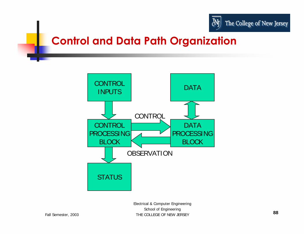
Control and Data Path Organization
Most complex digital circuits can be broken up into two parts:
ControlData Path
Fall Semester, 2003
Electrical & Computer EngineeringSchool of Engineering
THE COLLEGE OF NEW JERSEY 88
Control and Data Path Organization
CONTROLPROCESSING
BLOCK
DATAPROCESSING
BLOCK
DATACONTROLINPUTS
STATUS
CONTROL
OBSERVATION

Fall Semester, 2003
Electrical & Computer EngineeringSchool of Engineering
THE COLLEGE OF NEW JERSEY 89
Finite State Machines
Two Classes of Finite State Machines (FSMs):
Moore MachinesMealy Machines

Fall Semester, 2003
Electrical & Computer EngineeringSchool of Engineering
THE COLLEGE OF NEW JERSEY 90
Outputs depend only on the stateState and Outputs Processing are combinational elementsState Vector is Sequential Elements
Moore Finite State Machines
STATEVECTOR
OUTPUTSPROCESSING
NEXT STATEPROCESSING
CLOCK
OUTPUTSINPUTS

Fall Semester, 2003
Electrical & Computer EngineeringSchool of Engineering
THE COLLEGE OF NEW JERSEY 91
Outputs depend on the state and the inputs
Mealy Finite State Machines
STATEVECTOR
OUTPUTSPROCESSING
NEXT STATEPROCESSING
CLOCK
OUTPUTSINPUTS

Fall Semester, 2003
Electrical & Computer EngineeringSchool of Engineering
THE COLLEGE OF NEW JERSEY 92
Verilog IMPLEMENTATION EXAMPLES – A Decimation Filter for
a Sigma-Delta Analog to Digital Converter

Fall Semester, 2003
Electrical & Computer EngineeringSchool of Engineering
THE COLLEGE OF NEW JERSEY 93
2-Ch Σ-∆ Analog to Digital Converter
Bandgap~ 1.25V
Digital Filter(Sinc3)
Digital Design
V1P
V1N
xx REF+
V21P
V21N
Clock GenerationG3
x1, x2, x8, x16
PGA Integrators / Comparator
PGA Integrators / Comparator
x1, x2, x8, x16
M
L
L
L Digital Filter(Sinc3)
Analog Design
Σ−∆ ADC
SYNC
G2G1G0
CLKPD1PD2PD3
2nd Order Σ−∆ Modulators
RSTN
CMP1
CMP2

Fall Semester, 2003
Electrical & Computer EngineeringSchool of Engineering
THE COLLEGE OF NEW JERSEY 94
2nd Order Σ-∆ Modulator (block/algorithmic)
z-1
z-1
IN
OUT
CREF
1 / CFA CX / CFBCIN
CY / CFB
This can be modeled in Behavioral Verilog

Fall Semester, 2003
Electrical & Computer EngineeringSchool of Engineering
THE COLLEGE OF NEW JERSEY 95
2nd Order Σ-∆ Modulator (circuit)
This can also be modeled in Behavioral Verilog
VCMI
VCMI
VCMI
CAZ
CAZ
CFA
CFA
VCMI
VCMI
CIN
CIN
CY
CX
CX
CY
CFB
CFB
CREF
CREF
AZB
AZB
AZB
AZ
AZ
T1
T2
T2
T1
B1
B2
B2
B1
B1
B2
B2
B1
B2 S1
B2
B1 S2
B1 S2
S1
STRB
REF+
REF-
IN+
IN-
FL
FL
“1”
“0”
“0”
“1”
AMP1 AMP2
Fall Semester, 2003
Electrical & Computer EngineeringSchool of Engineering
THE COLLEGE OF NEW JERSEY 96
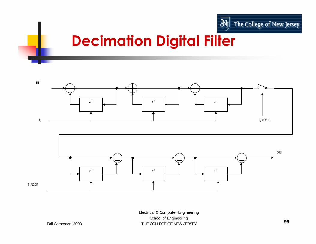
Decimation Digital Filter
z-1 z-1 z-1
z-1 z-1 z-1
fs
fs / OSR
IN
OUT
fs / OSR

Fall Semester, 2003
Electrical & Computer EngineeringSchool of Engineering
THE COLLEGE OF NEW JERSEY 97
Decimation Digital Filter
Cubic sincBits of noise free accuracy for delta-sigma ADC's:
BITS = 3 * LOG(OSR) / LOG(2) + 2Assume OSR=32, then BITS=17, and set BITS=16

Fall Semester, 2003
Electrical & Computer EngineeringSchool of Engineering
THE COLLEGE OF NEW JERSEY 98
Decimation Digital Filter
First Filter EquationsH1(z) = Y1(z)/X(z) = 1/(1 - 3 z-1 + 3 z-2 - z-3)y1(n) = x(n) + 3 y1(n-1) - 3 y1(n-2) + y1(n-3)
Second Filter EquationsH2(z) = Y(z)/X1(z) = 1 - 3 z-1 + 3 z-2 - z-3
y(n) = x1(n) - 3 x1(n-1) + 3 x1(n-2) - x1(n-3)
Decimation (Retiming)x1(n)=y1(n/OSR)x1(n)=y1(n/32)

Fall Semester, 2003
Electrical & Computer EngineeringSchool of Engineering
THE COLLEGE OF NEW JERSEY 99
What do we need for our design?y1(n) = x(n) + 3 y1(n-1) - 3 y1(n-2) + y1(n-3)y(n) = x1(n) - 3 x1(n-1) + 3 x1(n-2) - x1(n-3)x1(n)=y1(n/32)
ControlOn every x(n)
S02: Store x(n) in accumulator, count x(n) mod 32S03: Accumulate 2 y1(n-1)S04: Accumulate y1(n-1)S05: Accumulate 1’s complement of 2 y1(n-2)S06: Accumulate 1’s complement of y1(n-2)S07: Accumulate 2S08: Accumulate y1(n-3)S09: Update y registers
On every x1(n) (every 32nd y1(n))S10: Accumulate 1’s complement of 2 x1(n-1)S11: Accumulate 1’s complement of x1(n-1)S12: Accumulate 2 x1(n-2)S13: Accumulate x1(n-2)S14: Accumulate 1’s complement of x1(n-3)S15: Accumulate 3, output resultS16: Store y1(n-1) in accumulatorS17: Update x registers
Data Path16 bitsAdder-Accumulator1’s complementShift left by one (x 2)Store y1(n-1), y1(n-2), y1(n-3)Store x1(n-1), x1(n-2), x1(n-3)Constants: 2 & 3

Fall Semester, 2003
Electrical & Computer EngineeringSchool of Engineering
THE COLLEGE OF NEW JERSEY 100
OUT
Decimation Digital Filter Architecture
Ry1_n_1 Ry1_n_2 Ry1_n_3 Rx1_n_1 Rx1_n_2 Rx1_n_3
ACCUMULATOR
x2, PASS
1’S COMP., PASS, 2, 3
xn
URy
S1
S2
S3
S4
CONTROLLER
S1
S2
S3
S4
URy
URx
OSS
DATA-PATH
URx
ISS

Fall Semester, 2003
Electrical & Computer EngineeringSchool of Engineering
THE COLLEGE OF NEW JERSEY 101
Verilog code for Data_Path
// Data_Pathmodule Data_Path (CLK, reset, xn, URy, URx,
S2, S3, S4, S1, S3, S4,S1, OUTPUT);
input CLK, reset, xn, URy, URx, S2;input [1:0] S3, S4;input [2:0] S1;output [15:0] OUTPUT;

Fall Semester, 2003
Electrical & Computer EngineeringSchool of Engineering
THE COLLEGE OF NEW JERSEY 102
reg [15:0] Ry1_n_1, Ry1_n_2, Ry1_n_3;reg [15:0] Rx1_n_1, Rx1_n_2, Rx1_n_3;reg [15:0] ACCUMULATOR;
parameter my_zero = 16’b0000000000000000;
reg [15:0] T1, T2, T3, T4, T5;reg my_msb;
assign OUTPUT = ACCUMULATOR;
always @ (posedge CLK or reset) beginif (reset == 1’b1) begin
Ry1_n_1 = my_zero; Ry1_n_2 = my_zero; Ry1_n_3 = my_zero;Rx1_n_1 = my_zero; Rx1_n_2 = my_zero; Rx1_n_3 = my_zero;ACCUMULATOR = my_zero;
else if (CLK == 1’b1) beginif (URy == 1’b1) beginRy1_n_3 = Ry1_n_2; Ry1_n_2 = Ry1_n_1;Ry1_n_1 = ACCUMULATOR;
endif (URx == 1’b1) begin
Rx1_n_3 = Rx1_n_2; Rx1_n_2 = Rx1_n_1;Rx1_n_1 = ACCUMULATOR;
endcase (S1)
3’b000 : T1 = Ry1_n_1;3’b001 : T1 = Ry1_n_2;
Verilog code for Data_Path3’b010 : T1 = Ry1_n_3;3’b011 : T1 = Rx1_n_1;3’b100 : T1 = Rx1_n_2;3’b101 : T1 = Rx1_n_3;
endcasecase (S2)
1’b0 :my_msb = T1[15];T2 = T1 << 1;T3 = T2 & 16’b0111111111111111;T4 = T3 | {my_msb, 15’b000000000000000};
1’b1 : T4 = T1;endcasecase (S3)
2’b00 : T5 = ~T4;2’b01 : T5 = T4;2’b10 : T5 = 16’b0000000000000010;2’b11 : T5 = 16’b0000000000000011;
endcasecase (S4)
2’b00 : ACCUMULATOR = {15’b000000000000000, xn};2’b01 : ACCUMULATOR = Ry1_n_1;2’b10 : ACCUMULATOR = ACCUMULATOR + T5;
endcaseend
endendmodule

Fall Semester, 2003
Electrical & Computer EngineeringSchool of Engineering
THE COLLEGE OF NEW JERSEY 103
Verilog code for Controller
// Controllermodule Controller (CLK, reset, ISS, URy, URx,
S2, OSS, S3, S4, S1);
input CLK, reset, ISS;output URy, URx, S2, OSS;output [1:0] S3, S4;output [2:0] S1;

Fall Semester, 2003
Electrical & Computer EngineeringSchool of Engineering
THE COLLEGE OF NEW JERSEY 104
parameter S00 = 5’h00, S01 = 5’h01, S02 = 5’h02, S03 = 5’h03,S04 = 5’h04, S05 = 5’h05, S06 = 5’h06, S07 = 5’h07, S08 = 5’h08,S09 = 5’h09, S10 = 5’h0A, S11 = 5’h0B, S12 = 5’h0C, S13 = 5’h0D,S14 = 5’h0E, S15 = 5’h0F, S16 = 5’h10, S17 = 5’h11;
reg URy, URx, S2, OSS;reg [1:0] S3, S4;reg [2:0] S1;
reg [4:0] PRState, NXState;
reg [4:0] Counter;
always @ (PRState) beginif (PRState == S09) URy = 1’b1;else URy = 1’b0;if (PRState == S17) URx = 1’b1;else URx = 1’b0;if (PRState == S05 || PRState == S06) S1 = 3’b001;else if (PRState == S08) S1 = 3’b010;else if (PRState == S10 || PRState == S11) S1 = 3’b011;else if (PRState == S12 || PRState == S13) S1 = 3’b100;else if (PRState == S14) S1 = 3’b101;else S1 = 3’b000;
Verilog code for Controllerif (PRState == S03 || PRState == S05 ||
PRState == S10 || PRState == S12) S2 = 1’b0;else S2 = 1’b1;if (PRState == S05 || PRState == S06 ||
PRState == S10 || PRState == S11 ||PRState == S14) S3 = 2’b00;
else if (PRState == S07) S3 = 2’b10;else if (PRState == S15) S3 = 2’b11;else S3 = 2’b01;if (PRState == S02) S4 = 2’b00;else if (PRState == S16) S4 = 2’b01;else S4 = 2’b10;if (PRState == S15) OSS = 1’b1;else OSS = 1’b0;
end

Fall Semester, 2003
Electrical & Computer EngineeringSchool of Engineering
THE COLLEGE OF NEW JERSEY 105
always @ (posedge CLK or reset) beginif (reset == 1’b1) begin
PRState = S00;Counter = 5’b00000;
endelse if (CLK == 1’b1) begin
PRState = NXState;if (Counter == 5’b11111) Counter = 5’b00000;else Counter = Counter + 5’b00001;
endendalways @ (PRState) begin
case (PRState)S00 : if (ISS == 1’b1) NXState = S02;S01 : if (ISS == 1’b1) NXState = S02;S02 : NXState = S03;S03 : NXState = S04;S04 : NXState = S05;S05 : NXState = S06;S06 : NXState = S07;
Verilog code for ControllerS07 : NXState = S08;S08 : NXState = S09;S09 : if (Counter == 5’b00000) NXState = S10;
else NXState = S01;S10 : NXState = S11;S11 : NXState = S12;S12 : NXState = S13;S13 : NXState = S14;S14 : NXState = S15;S15 : NXState = S16;S16 : NXState = S17S17 : NXState = S01;
endcaseend
endmodule

Fall Semester, 2003
Electrical & Computer EngineeringSchool of Engineering
THE COLLEGE OF NEW JERSEY 106
Main Code for FILTER
module FILTER (reset, CLK, ISS, xn,OSS, OUTPUT);
input reset, CLK, ISS, xn;output OSS;output [15:0] OUTPUT;

Fall Semester, 2003
Electrical & Computer EngineeringSchool of Engineering
THE COLLEGE OF NEW JERSEY 107
wire URy, URx, S2;wire [1:0] S3, S4;wire [2:0] S1;
Controller c (.CLK(CLK), .reset(reset),.ISS(ISS), .URy(URy), .URx(URx), .S2(S2),.OSS(OSS), .S3(S3), .S4(S4), .S1(S1));
Data_Path dp (.CLK(CLK), .reset(reset),.xn(xn), .URy(URy), .URx(URx), .S2(S2),.S3(S3), .S4(S4), .S1(S1), .OUTPUT(OUTPUT));
endmodule
Main Code for FILTER Cont…

Fall Semester, 2003
Electrical & Computer EngineeringSchool of Engineering
THE COLLEGE OF NEW JERSEY 108
Conclusions

Fall Semester, 2003
Electrical & Computer EngineeringSchool of Engineering
THE COLLEGE OF NEW JERSEY 109
Conclusions

Fall Semester, 2003
Electrical & Computer EngineeringSchool of Engineering
THE COLLEGE OF NEW JERSEY 110
http://www.tcnj.edu/~hernande/
Thanks……


![“A Verilog OverviewA Verilog Overview”hernande/Eng312/TCNJ_Verilog(R)_V...Comparator Verilog Source Code // Eight-bit Comparator module compare (A, B, EQ) input [7:0] A, B; output](https://static.fdocuments.net/doc/165x107/5f8b8feb76f68678470c12e5/aoea-verilog-overviewa-verilog-overviewa-hernandeeng312tcnjverilogrv.jpg)