

Applications & Specifications Class 5600 I-LINE Busbar Trunking ...

Busbar trunking systemSIVACON 8PS - Installation with LR system
Installation Manual 04/2011•
Low-Voltage Power Distribution andElectrical Installation TechnologyAnswers for infrastructure.Siemens Spares


Low-voltage power distribution and electrical installation technology Busbar trunking systemSIVACON 8PS - Installation with LR system
Installation Manual
04/2011 A5E00949793-01
Introduction 1
Application planning 2
Installation 3
Commissioning 4
Service and maintenance 5
Weights 6
Test reports 7
Safety data sheets 8
Siemens Spares

Legal information Warning notice system
This manual contains notices you have to observe in order to ensure your personal safety, as well as to prevent damage to property. The notices referring to your personal safety are highlighted in the manual by a safety alert symbol, notices referring only to property damage have no safety alert symbol. These notices shown below are graded according to the degree of danger.
DANGER indicates that death or severe personal injury will result if proper precautions are not taken.
WARNING indicates that death or severe personal injury may result if proper precautions are not taken.
CAUTION with a safety alert symbol, indicates that minor personal injury can result if proper precautions are not taken.
CAUTION without a safety alert symbol, indicates that property damage can result if proper precautions are not taken.
NOTICE indicates that an unintended result or situation can occur if the relevant information is not taken into account.
If more than one degree of danger is present, the warning notice representing the highest degree of danger will be used. A notice warning of injury to persons with a safety alert symbol may also include a warning relating to property damage.
Qualified Personnel The product/system described in this documentation may be operated only by personnel qualified for the specific task in accordance with the relevant documentation, in particular its warning notices and safety instructions. Qualified personnel are those who, based on their training and experience, are capable of identifying risks and avoiding potential hazards when working with these products/systems.
Proper use of Siemens products Note the following:
WARNING Siemens products may only be used for the applications described in the catalog and in the relevant technical documentation. If products and components from other manufacturers are used, these must be recommended or approved by Siemens. Proper transport, storage, installation, assembly, commissioning, operation and maintenance are required to ensure that the products operate safely and without any problems. The permissible ambient conditions must be complied with. The information in the relevant documentation must be observed.
Trademarks All names identified by ® are registered trademarks of Siemens AG. The remaining trademarks in this publication may be trademarks whose use by third parties for their own purposes could violate the rights of the owner.
Disclaimer of Liability We have reviewed the contents of this publication to ensure consistency with the hardware and software described. Since variance cannot be precluded entirely, we cannot guarantee full consistency. However, the information in this publication is reviewed regularly and any necessary corrections are included in subsequent editions.
Siemens AG Industry Sector Postfach 48 48 90026 NÜRNBERG GERMANY
A5E00949793-01 Ⓟ 06/2012 Technical data subject to change
Copyright © Siemens AG 2011. All rights reserved

SIVACON 8PS - Installation with LR system Installation Manual, 04/2011, A5E00949793-01 3
Table of contents
1 Introduction................................................................................................................................................ 5
1.1 Introduction ....................................................................................................................................5
2 Application planning................................................................................................................................... 7
2.1 Scope of delivery ...........................................................................................................................7
2.2 Receiving goods ............................................................................................................................7
2.3 Safe handling .................................................................................................................................8
2.4 Storage...........................................................................................................................................9
2.5 Packaging ....................................................................................................................................11
2.6 Handling .......................................................................................................................................12
3 Installation ............................................................................................................................................... 15
3.1 Overview ......................................................................................................................................15
3.2 Installing a busbar run..................................................................................................................22
3.3 Attaching fixing material...............................................................................................................25 3.3.1 Overview ......................................................................................................................................25 3.3.2 Bracket for horizontal installations ...............................................................................................26 3.3.3 Spring brackets for vertical installation on walls ..........................................................................31 3.3.4 Floor fixing for spring brackets.....................................................................................................34 3.3.5 Fixing brackets with fixed point for vertical installation ................................................................36
3.4 Connecting units ..........................................................................................................................38 3.4.1 Preparing the elements for connection ........................................................................................38 3.4.2 Establishing the electrical connection..........................................................................................40
3.5 Expansion unit..............................................................................................................................45
3.6 Terminal elements .......................................................................................................................46 3.6.1 Storage prior to installation ..........................................................................................................46 3.6.2 Installation....................................................................................................................................47 3.6.3 Positioning the connection unit above the transformer................................................................48 3.6.4 Handling if multiple busbar runs are laid in parallel .....................................................................49
3.7 Fire barrier....................................................................................................................................50 3.7.1 Fire barrier regulations.................................................................................................................50
3.8 Tap-off unit ...................................................................................................................................52
4 Commissioning ........................................................................................................................................ 53
4.1 Steps to be performed prior to electrification of the line ..............................................................53
4.2 Electrifying the line.......................................................................................................................54
5 Service and maintenance ........................................................................................................................ 55
6 Weights.................................................................................................................................................... 57
Siemens Spares
Table of contents
SIVACON 8PS - Installation with LR system 4 Installation Manual, 04/2011, A5E00949793-01
7 Test reports ............................................................................................................................................. 59
7.1 Test report for inspecting assembled joint blocks on initial assembly ........................................ 60
7.2 Test report for inspecting assembled joint blocks on subsequent assembly.............................. 61
7.3 Insulation test report.................................................................................................................... 62
8 Safety data sheets ................................................................................................................................... 63
8.1 Safety data sheet demoulding agent .......................................................................................... 63
8.2 Safety data sheet BKS 1 epoxy resin mix................................................................................... 70
8.3 Safety data sheet BKS 2 mix ...................................................................................................... 78
Index........................................................................................................................................................ 85

SIVACON 8PS - Installation with LR system Installation Manual, 04/2011, A5E00949793-01 5
Introduction 11.1 Introduction
This manual is designed to assist you in installing, maintaining and commissioning LR systems.
Note
Before installing the system on the site, you must read and follow the instructions on storage, transport and handling.
NOTICE Only personnel who have been trained in site safety regulations (such as the wearing of helmets, safety goggles, safety shoes, high-visibility tabards, etc.) may work on construction sites and install busbar trunking systems. The responsible safety officer must provide mandatory safety training.
Manual overview This manual consists of four sections:
● General information: Brief overview of busbar trunking system components and how they are installed
● Installation: Description of how the busbar trunking system elements are installed
● Inspection, expansions, checks: Description of how to handle the busbar trunking system once it has been installed
● Checklists and reports
● Safety data sheet Chemlease 2298: Mix consisting of the materials listed below, special silicon oils and solvents (hydrocarbons).
● Safety data sheets mix BKS 1, bisphenol A epoxy resin with reactive thinner and mix BKS 2, polyaminoamide.
You can find more detailed technical information on LR systems in the planning manual "Planning with SIVACON 8PS" (Order number: A5E01541017).
In addition, observe the installation instructions (A5E...) for the individual busbar elements. These contain specific details on how to install the various busbar elements. You can find an overview of the installation instructions in the Chapter "Installing the busbar run" (Page 22).
Siemens Spares
Introduction 1.1 Introduction
SIVACON 8PS - Installation with LR system 6 Installation Manual, 04/2011, A5E00949793-01

SIVACON 8PS - Installation with LR system Installation Manual, 04/2011, A5E00949793-01 7
Application planning 22.1 Scope of delivery
All materials are packaged and sent out together with a delivery note and installation instructions.
2.2 Receiving goods ● Check that the material and documentation received corresponds to the scope of your
installation project.
● Check the components supplied and ensure that they function as intended and correspond with the information on the documentation.
● Take particular note of the information on the packaging (symbols, labels, etc.). Observe the warning notices.
● The item number on the packaging and the project manual will help you to identify where the element is to be installed in the layout.
● Check that the material has been delivered in perfect condition and with no transport damage.
Siemens Spares

Application planning 2.3 Safe handling
SIVACON 8PS - Installation with LR system 8 Installation Manual, 04/2011, A5E00949793-01
2.3 Safe handling
Handling material
NOTICE As with all electrical equipment, this material should be handled with care, following the instructions listed here.
Proceed with caution and pay attention to personnel safety. Use all equipment necessary for correct handling of the material.
Required measures
● Ventilate the work site well
● Avoid breathing in any vapours or fumes
● Wear protective goggles, gloves or overalls
● Apply a protective cream to any unprotected areas of skin to avoid sensitization
● Do not eat, drink or smoke at the work site
● Wash your hands with soap and warm water after use
● In the event of unintentional spillage, mix the unmixed resin and hardening agents with absorbent inert material (e.g. sand) and keep it in a suitable sealable container prior to disposal
● Submit filled containers for resin and hardening agents either for incineration or storage, according to local regulations.

Application planning 2.4 Storage
SIVACON 8PS - Installation with LR system Installation Manual, 04/2011, A5E00949793-01 9
2.4 Storage 1. The material storage area has to meet the following requirements:
– It must be stable, secure and not on a slope.
– It must be protected against damp, extreme temperatures and water penetration. The temperature for storing the busbar must not be lower than -5 °C, the cast resin mix and the demoulding agent must not be stored below +5 °C, or below +15 °C 24 hours before use.
– Effective protection against dust, water, welding sparks, direct sunlight and other factors that could damage the material supplied must be in place.
– For safety reasons, the area must not serve as a gangway, nor must it be used to assemble other equipment.
2. Take note of the specific storage and packaging information featured on the packaging (symbols, labels, etc.).
3. If possible, store the material in its transport packaging. As a rule, the elements are supplied on pallets measuring 0.8 m x 3 m with a maximum load-carrying capacity of 2,000 kg. In the case of pallets with straight elements, no more than 5 pallets must be stacked on top of each other. Smaller elements, casting moulds, accessories, etc. are packed on pallets measuring 0.8 m x 1.20 m with a maximum load-carrying capacity of 1,500 kg.
Siemens Spares

Application planning 2.4 Storage
SIVACON 8PS - Installation with LR system 10 Installation Manual, 04/2011, A5E00949793-01
4. If the transport packaging is removed, store the elements in their product packaging as follows:
– Straight lengths: In single systems a maximum of four and in double systems a maximum of two elements may be stacked edgewise on top of one another, and a maximum of 4 elements may be stacked flat on top of one another. Use wooden blocks (25 mm x 100 mm) to separate the individual layers.
Figure 2-1 Storing single systems upright and flat
Figure 2-2 Storing double systems upright and flat
– All other elements such as junction units, flanged ends, AS transformer feeder units and incoming cable connection units must not be stacked.
5. Special handling applies to flanged ends and transformer feeder units. You can find more detailed information in the chapters "Flanged ends" and "Transformer connections".

Application planning 2.5 Packaging
SIVACON 8PS - Installation with LR system Installation Manual, 04/2011, A5E00949793-01 11
2.5 Packaging The busbar trunking system elements are supplied with protective packaging on their ends. These protect conductors, insulators and joint blocks against impact during transport and storage. The protective foil/packaging also protects the elements from dust and damp.
As a rule, the straight elements are supplied on pallets measuring: 0.8 m x 3 m with a maximum load-carrying capacity of 2,000 kg. In the case of pallets with straight elements, no more than 5 pallets must be stacked on top of each other. Smaller elements, casting moulds, accessories, etc. are packed on pallets measuring 0.8 m x 1.20 m with a maximum load-carrying capacity of 1,500 kg. The pallets are only provided with a frame and cover as extra protection if necessary.
No additional packaging is required for cross-country road transport (truck freight). When unloading, ensure the pallets and crates are well secured to protect the freight from external influences.
For transport by sea, all pallets and crates (export crates) are packed appropriately. The standard crate measurements are: 3150/1000/1000 mm. The floors of the crates are made of 30 mm thick spruce, the side panels of 12 mm thick plywood panels, and the top cover of akylux. The sides and top cover are protected with clupak paper. The max. load-carrying capacity of the crates is 2.5 tons.
All pallets and crates are heat-treated to 75 °C/165 °F for 48 hours and IPPC-stamped. A certificate is supplied.
For large projects, all pallets and frame pallets are loaded into marine containers. Six-meter marine containers with a max. load-carrying capacity of 20 tons are used. The bases of the pallets are screwed to the floor of the container. All pallets are additionally secured with two heavy-duty strap retainers.
For air transport, all busbar trunking system elements and accessories are packed on pallets with frames or in crates.
The epoxy resin and hardening agents are required for making the cast resin mix. These materials are regarded as hazardous for the purposes of air transport. For this reason, they are shipped with special packaging and labelling in accordance with IATA regulations. This must be specified when ordering.
NOTICE Be very careful when removing the strap retainers. The sharp edges on the strap retainers pose a significant risk of injury when they spring off.
Note
The protective material can be recycled. When disposing of it, refer to the applicable standards for waste disposal in the installation area.
Siemens Spares

Application planning 2.6 Handling
SIVACON 8PS - Installation with LR system 12 Installation Manual, 04/2011, A5E00949793-01
2.6 Handling All pallets can be transported using a forklift truck. To simplify loading and unloading, the pallets can be carried from all sides. All elements on the pallets are protected with wooden spacers and metal hoops.
For safe loading and unloading of marine containers, a minimum forklift hoisting power of 4.5 tons is required. To safely lift the pallets at the narrow side (0.8 m), the forklift must have a minimum fork length of 2 m.
Busbar trunking system elements can be moved using a forklift and/or suspended from slings.
Figure 2-3 Transporting with a forklift truck
Application planning 2.6 Handling
SIVACON 8PS - Installation with LR system Installation Manual, 04/2011, A5E00949793-01 13
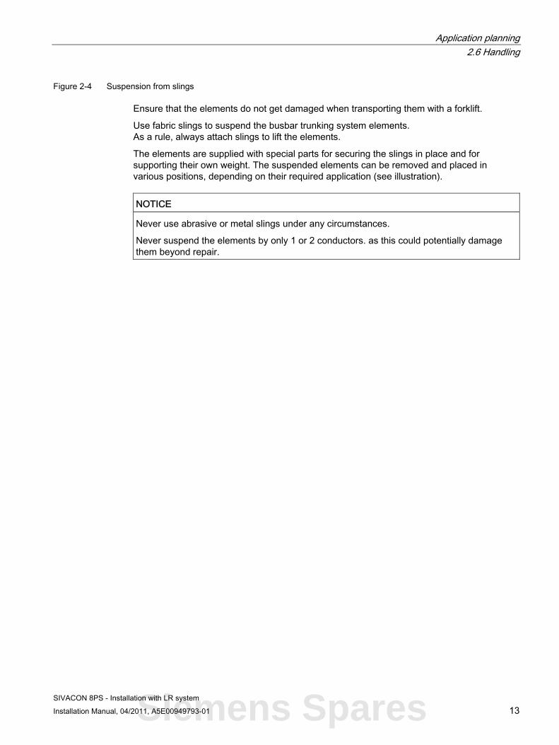
Figure 2-4 Suspension from slings
Ensure that the elements do not get damaged when transporting them with a forklift.
Use fabric slings to suspend the busbar trunking system elements. As a rule, always attach slings to lift the elements.
The elements are supplied with special parts for securing the slings in place and for supporting their own weight. The suspended elements can be removed and placed in various positions, depending on their required application (see illustration).
NOTICE Never use abrasive or metal slings under any circumstances.
Never suspend the elements by only 1 or 2 conductors. as this could potentially damage them beyond repair.
Siemens Spares

Application planning 2.6 Handling
SIVACON 8PS - Installation with LR system 14 Installation Manual, 04/2011, A5E00949793-01

SIVACON 8PS - Installation with LR system Installation Manual, 04/2011, A5E00949793-01 15
Installation 33.1 Overview
Procedure for installing the busbar elements 1. Checking elements:
Inspect all elements on receipt and ensure that neither the conductors nor their insulation have been damaged during handling and/or storage.
2. Before assembling the run, each individual element must be checked to ensure that the insulation resistance of the conductors is ≥ 1 MΩ.
3. Correct installation sequence: Install the elements in accordance with the planned layout as indicated in the installation drawings supplied. For the purposes of installation and insulation measurement, the run must be divided into sub-sections with no more than 6 segments.
4. Connecting elements:
– Ensure that the spacing between adjoining elements (30 mm ± 5 mm) is correct.
– Check that the insulation of the busbar, conductor and monobloc plate is clean and dry; clean the contact point of the conductors and the conductor ends with a cleaning pad. If necessary, remove the dust and dry the parts with an air dryer.
– Check that the insulation resistance of the conductors is ≥ 1 MΩ. No other equipment (transformers, tap-off units, end feed units, etc.) must be connected at this time. See chapter "Commissioning" (Page 53).
– Place the joint block between the elements and establish the electrical and mechanical connection between the conductors. Tighten the nut to 40 or 84 Nm.
5. Closing the junctions:
– Apply the neoprene seals to both sides of the mould (tongue and groove).
– Brush the demoulding agent onto the inside of the casting mould and the seals, and allow the demoulding agent to dry.
– Place the casting mould on the mechanical connection (joint block) and secure it with the 2 C-profiles.
– Prepare as many casting moulds as possible for casting. Note: The casting mould must overlap the insulation of the two busbar element ends by at least 2 cm.
Siemens Spares

Installation 3.1 Overview
SIVACON 8PS - Installation with LR system 16 Installation Manual, 04/2011, A5E00949793-01
6. Mixing the cast resin mix:
– Handling and safety precautions:
⇒Good ventilation of the work site
⇒Avoid breathing in vapours and fumes
⇒Wear protective goggles, gloves or overalls
⇒Apply a protective cream to any unprotected areas of skin to avoid sensitization
⇒Do not eat, drink or smoke at the work site
⇒Thoroughly wash your hands with soap and warm water after use
⇒In the event of unintentional spillage, mix the unmixed resin and hardening hardening agent with absorbent inert material (e.g. sand) and keep it in a suitable sealable container prior to disposal
⇒Filled containers for resin and hardening agent must be submitted either for incineration or
⇒storage, according to local regulations.
– Check that the resin is clear and liquid. Do not use the resin if it is milky or crystallized.
– Check the best-before date on the label. If it is out of date, contact the company. Never exceed the permissible best-before date.
– Check that the filler material/sand is dry.
– The resin for casting the connection is mixed in a tub. The necessary number of casting units for a project is taken into account on delivery. A reserve of approx. 5% is always calculated. To avoid unnecessary waste (residue), several connections must always be prepared simultaneously.
– Open the tub and remove the cans with the resin and hardening agent. Practical note: The solids become compressed by shaking during transport and the cans are then difficult to remove. Before opening the tub, roll it a little on the floor to loosen the solids; the cans are then easy to remove.
– Fill the resin (comp. A) and hardening agent (comp. B) into the empty tubs supplied and mix using a mixer (750 or 900 W, 220 V, 50 Hz) for 1 minute.
– Pour the filler material in three phases into the mixture of resin and hardening agent, and mix each time until the cast resin mix becomes homogenous. The entire mixing time must be a total of approx. 3 minutes, approx. 1 minute per phase.
– Required material:

Installation 3.1 Overview
SIVACON 8PS - Installation with LR system Installation Manual, 04/2011, A5E00949793-01 17
a) Casting moulds — As ordered (see packing list)
b) Tub 12 l with cast resin mix 12 kg filler material Quantity as per order — 1 can of resin (comp. A)
1.8 kg —
— 1 can of hardening agent (comp. B) 1.8 kg
—
c) Tub 12 l empty 1 per delivery (free) — d) 1 l bottle with demoulding agent 0.5 kg contents — e) Electric handheld mixer and
mixing rods — To be provided by the
installation company f) Cleaning agent (CH2CL2) -
Methylene chloride — To be provided by the
installation company Substitute agent:
Trichloroethane, trichloroethane or acetone
— —
Storing the cast resin mix: Dry, not in direct sunlight, not under 5 °C and not over 40 °C. 24 hrs before use not under 15 °C.
7. Casting
– Avoid drafts and temperatures below +5 °C.
– Pour the cast resin mix slowly without hesitation or stopping up to the upper edge of the ready installed casting mould. Tap the cast resin mix gently with a rubber hammer to allow the bubbles to escape. Do not overfill; then smooth the surface with a putty knife.
– Allow the cast resin mix to harden. The hardening time is usually 5 to 14 hours; after hardening, the reusable casting mould is released. At an ambient temperature of 25 °C, carefully remove the casting mould after 5 hours (at 15 °C after 7 hours; at 10 °C after 10 hours, and at 5 °C after 14 hours). Thoroughly clean the casting mould after use.
– Use the supplied grinding stone to deburr the edges and remove any uneven spots. Like the overall system, the joint meets the protection requirements in accordance with IP68 (see also "Connecting elements (Page 38)").
– Clean all tools after use with solvent and allow them to dry thoroughly. Suitable solvents are methylene chloride (CH2CL2) or trichloroethane, solventane or acetone (acetone only if no other solvent is available; caution! danger of fire).
Siemens Spares

Installation 3.1 Overview
SIVACON 8PS - Installation with LR system 18 Installation Manual, 04/2011, A5E00949793-01
8. Amount of cast resin for straight connections
Amount of cast resin for straight connections
4-conductor 5-conductor Busbar type AL/CU
Tubs Tubs LRA/C 01 ... 03 0.60 0.60 LRA/C 04 0.65 0.80 LRA/C 05 0.70 0.85 LRA/C 06 0.80 0.95 LRA/C 07 0.90 1.10 LRA/C 08 1.05 1.25 LRA/C 09 1.20 1.35 LRA/C 27 1.60 1.95 LRA/C 28 1.85 2.20 LRA/C 29 2.15 2.50
Please note that a 5 to 10% reserve has been calculated into the quantities listed above.
Note
To be able to maintain the values in the table, you must cast as many connections as possible simultaneously. Conversely, if the casting mould is used several times (joints cast separately), the quantity must be calculated and mixed precisely.
Demoulding agent LRA/C 01 ... 03 For 1 to 25 connections 1 x 0.5 litres LRA/C 04 ... 06 For 1 to 20 connections 1 x 0.5 litres LRA/C 07 ... 09 For 1 to 15 connections 1 x 0.5 litres LRA/C 27 ... 29 For 1 to 10 connections 1 x 0.5 litres
Cleaning agent Solvent Methylene chloride (CH2CL2) Quantity: Minimum 5 litres
(For cleaning the mixer and the tools. To be provided by the installation company.)
1. Installation instructions schedule Schedule for nominal installation work in use and general industry.

Installation 3.1 Overview
SIVACON 8PS - Installation with LR system Installation Manual, 04/2011, A5E00949793-01 19
Horizontal installation
Installation time in hours LRA/C
01 - 03 AL/CU
04 AL/CU
05 AL/CU
06 AL/CU
07 AL/CU
08 AL/CU
09 AL/CU
27 AL/CU
28 AL/CU
29 AL/CU
Line compositi
on Straight element 1 m
1.2 1.3 1.4 1.5 1.8 12.0 2.2 3.6 4.0 4.4 —
Straight element 2 m
1.5 1.6 1.7 1.8 2.2 2.4 2.6 4.4 4.8 5.2 1
Straight element 3 m
1.8 1.9 2.0 2.1 2.6 2.8 3.2 5.2 5.6 6.4 7
Elbow edgewise/flat
1.8 1.9 2.0 2.1 2.6 2.8 3.2 5.2 5.6 6.4 4
Expansion element
2.2 2.3 2.4 2.5 2.8 3.0 3.5 5.6 6.0 7.0 —
Z units 1.8 1.9 2.0 2.1 2.6 2.8 3.2 5.2 5.6 6.4 — Double elbow
1.9 2.0 2.2 2.3 2.8 3.0 3.4 5.6 6.0 6.8 1
TE element 2.2 2.4 2.6 2.7 3.2 3.6 4.0 6.4 7.2 8.0 — Terminal element standard (TO/TX)
2.0 2.2 2.4 2.5 2.8 3.0 3.4 5.6 6.0 6.8 1
Terminal element Non-standard
3.0 3.2 3.4 3.5 3.7 4.0 4.2 7.4 8.0 8.4 1
Extra for vertical
0.5 0.7 1.0 1.2 1.4 1.7 2.0 2.8 3.4 4.0 —
Creation of the connection per element
0.5 0.7 0.9 1.1 1.2 1.4 1.6 2.4 2.8 3.2 14
Siemens Spares

Installation 3.1 Overview
SIVACON 8PS - Installation with LR system 20 Installation Manual, 04/2011, A5E00949793-01
Horizontal installation
Installation time in hours LRA/C
01 - 03 AL/CU
04 AL/CU
05 AL/CU
06 AL/CU
07 AL/CU
08 AL/CU
09 AL/CU
27 AL/CU
28 AL/CU
29 AL/CU
Line compositi
on Transformer Adapter box
— — — — — — — — — — 1
Control cabinet adapter box
— — — — — — — — — — —
Set of flexible connectors
— — — — — — — — — — 2
Set of laminated copper
— — — — — — — — — — —
Extra element with sealing ring
— — — — — — — — — — —
Extra element with bellows
— — — — — — — — — — —
Sun shade for laying outdoors
— — — — — — — — — — —

Installation 3.1 Overview
SIVACON 8PS - Installation with LR system Installation Manual, 04/2011, A5E00949793-01 21
Calculation based on an average line of 30 m length with 15 elements The installation schedule includes: • Erection of the standard support parts • Handling/positioning of the support parts • Checking the connection (visual/electrical) • Positioning of the casting mould • Mixing and casting • Demoulding and concluding tasks • Concluding insulation resistance test
The following are not included: • Unloading truck/container • Transporting to the construction site, from the
warehouse to the installation site • Vertical transport • Construction scaffolding • Non-standard support parts • Special paint finish
Corrections for shorter/longer lines 0 - 5 elements plus 10% 5 - 10 elements plus 5% 10 - 20 elements plus 0% 20 - 30 elements minus 5% >> 30 elements minus 10%
Reduction for parallel lines depending on the project arrangement We recommend that you possibly adjust the time in the case of • Petrochemicals/power plant + 10% • Plants on the high seas + 15%
1. Checking of the installed elements:
Check the insulation resistance of the run.
Siemens Spares

Installation 3.2 Installing a busbar run
SIVACON 8PS - Installation with LR system 22 Installation Manual, 04/2011, A5E00949793-01
3.2 Installing a busbar run
Installation The steps that must be performed to install the different LR system elements are described below, along with some accessories that have been designed for this purpose.
Although the parts are listed in order of installation, we do recommend that you read the instructions in full in order to familiarise yourself with the special characteristics of this installation procedure. In addition, the installation instructions for the busbars with cast resin insulation are included with the elements. Documents contain specific details on how to install the various busbar elements and must be followed at all times.
Note
A video clip demonstrating LR busbar installation is also available; please contact your SIEMENS contact for further available.
NOTICE Plan the installation process carefully, resolving all possible difficulties prior to starting work.
Always pay attention to personnel safety and ensure that material does not become damaged.

Installation 3.2 Installing a busbar run
SIVACON 8PS - Installation with LR system Installation Manual, 04/2011, A5E00949793-01 23
Overview of the installation instructions Elements Document No. Trunking Straight lengths L, Z and T units Expansion unit "Joint block" junctions Feeder units Transformer connections Flanged ends Siemens distribution board connections Incoming cable connection unit
A5E00949881
Accessories Fixing brackets for horizontal layout Fixing brackets for vertical layout Fire barrier to be mounted by the customer
A5E00949883 A5E00949883 A5E00949882
Installation recommendations
Install either the whole line or parts of it, depending on how accessible and safe the layout is.
1. Start the installation by connecting the board outlets.
2. Once the distribution board has been installed, continue towards the transformer, sub-distribution board and consumers.
3. Install the elements in accordance with the planned layout as indicated in the installation drawings supplied. For the purposes of installation and insulation measurement, the run must be divided into sub-sections with no more than 6 segments.
Figure 3-1 Straight trunking unit, last element to be assembled
Siemens Spares

Installation 3.2 Installing a busbar run
SIVACON 8PS - Installation with LR system 24 Installation Manual, 04/2011, A5E00949793-01
To simplify handling, on runs between feeder units the last element to be inserted should be a straight trunking unit.
NOTICE Protection and safety • Protect all elements from adverse ambient conditions and other potentially damaging
agents until installation has been completed. • Always pay attention to the safety of personnel and ensure that material does not get
damaged.
Note Deviating from the recommendations
These installation recommendations specify the general assembly sequence for the various busbar trunking system elements. As local conditions on the building site or within a project can vary, deviations from these recommendations are possible. In such cases, please get in touch with your SIEMENS contact.
The fixing bracket should be attached to the wall using plugs appropriate to the weight to be supported and the fixing material used.

Installation 3.3 Attaching fixing material
SIVACON 8PS - Installation with LR system Installation Manual, 04/2011, A5E00949793-01 25
3.3 Attaching fixing material The LR busbar trunking system is generally attached to the structural elements of the building using the supporting structures provided on site (e.g. wall beams or stands for intermediate levels) and the system-specific fixing brackets, threaded rods, and C-profiles.
3.3.1 Overview
Types of fixing material ● Fixing material not available in the catalogue (e.g. plugs, beams, suspension struts, etc.)
must be provided by installation experts.
● Bracket for horizontal installations (ceiling/wall/floor brackets, fixed points)
● Brackets for vertical installations (wall and ceiling brackets, fixed points, sliding fixing without spring elements, and load-bearing fixing with spring elements)
Attaching fixing material
In all cases, proceed as follows:
1. Attach the fixing brackets to the building via the supporting structure.
2. Raise the LR system and suspend it on the brackets without securing it.
3. The ideal distance for fixings is 1.5 m in straight busbar runs, or 2 m for 2 fixings in the case of straight lengths.
4. All fixing points are indicated in the installation drawing. The type of fixing varies for the different installation methods and can be seen from the detailed drawings. Fixed points must be used in the case of expansions.
5. Secure the element.
Note Consulting installation experts
These instructions only refer to accessories manufactured by SIEMENS. For further information, please refer to the catalogue.
It is beyond the scope of this manual to document the vast number of different on-site conditions that may arise. Therefore, we recommend that installation experts evaluate on-site conditions.
WARNING
Always follow the instructions provided in the manual and the installation instructions.
Siemens Spares

Installation 3.3 Attaching fixing material
SIVACON 8PS - Installation with LR system 26 Installation Manual, 04/2011, A5E00949793-01
3.3.2 Bracket for horizontal installations
Ceiling bracket ● Attach the suspension bracket LR..-BH. to the ceiling or another suitable structural
support.
● Ensure that the ceiling or structural support is strong enough (load-bearing) to hold the weight of the system.
● Place the element to be suspended in its intended final position on the brackets, leaving the element in a horizontal position.
● Join the adjacent elements and secure them using the C-profile.
● The C-profile can be used for horizontal element installation, flat or edgewise.
● The exact configuration will depend on on-site conditions.
● The surface finish of the threaded rods and the screws used must be adapted to on-site ambient conditions.
Ceiling fixing examples: suspended installation Description
Component part of the fixing sets LR..-BH. (Suspension up to 1 m below the ceiling):
① Threaded rods suspension
② C-profiles
③ Plugs
Component part of the fixing sets LR..BHH / LR..BHF: 2 threaded rods M10 for connecting the C-profiles2 C-profiles 4 lock nuts with spring washers (Threaded rods for suspension must be provided by the customer).
Detailed view of the C-profile, fixing set, installation positions: left-hand image horizontal, flat; right-hand image horizontal, edgewise, for the ceiling

Installation 3.3 Attaching fixing material
SIVACON 8PS - Installation with LR system Installation Manual, 04/2011, A5E00949793-01 27
Wall bracket ● Attach the suspension bracket (wall beam) LR..-BHW. to the wall or another suitable
structural support.
● Ensure that the wall or structural support is strong enough to hold the weight of the system.
● Place the element to be suspended in its intended final position on the wall beam, leaving the element in a horizontal position.
● Connect the following elements and fix these with the fixing bracket (elbow) straight onto the wall beams (see figure).
● The exact configuration will depend on on-site conditions.
Figure 3-2 Wall fixing example: supported installation
Elevated floor installation (on request)
Figure 3-3 Floor fixing example: elevated installation
Siemens Spares

Installation 3.3 Attaching fixing material
SIVACON 8PS - Installation with LR system 28 Installation Manual, 04/2011, A5E00949793-01
Attaching the ceiling bracket Before attaching the bracket, make sure you are aware of exactly what type of bracket is being used and exactly where it needs to be positioned.
● Take the following specifications into account:
– An element must never be left unsupported. For easier levelling, always use two supports for each element wherever possible.
– A bracket must never coincide with a joint block. Always maintain a distance of at least 250 mm between the centre of the joint block and the bracket.
– To meet the specific static circumstances when using fixed point brackets, we recommend using supporting structures with transverse stays. Siemens does not supply supporting structures. Please contact the special suppliers of such materials.
Figure 3-4 Bracket for LR element mounted edgewise
Figure 3-5 Bracket for LR element mounted flat

Installation 3.3 Attaching fixing material
SIVACON 8PS - Installation with LR system Installation Manual, 04/2011, A5E00949793-01 29
Figure 3-6 Using transverse stays for fixed points
● Never support an element at any point other than a fixing bracket. The maximum distance between horizontal fixing brackets will depend on their design (load capacity...); in theory, 1.5 m is considered a suitable distance. Greater distance between fixing brackets only on request.
Trunking weights and bracket distances Type LR LRA
01 LRA 02
LRA 03
LRA 04
LRA 05
LRA 06
LRA 07
LRA 08
LRA 09
LRA 27 LRA 28 LRA 29
Horizontal, edgewise
m 1.5 1.5 1.5 1.5 1.5 1.5 1.5 1.5 1.5 1.5 1.5 1.5
Horizontal, flat
m 1,5 1,5 1,5 1,5 1,5 1,5 1,5 1,5 1,5 1,5 1,5 1,5
Weight 4-conductor
kg 16.42 16.56 16.84 22.30 25.99 29.10 32.64 43.62 50.97 73.30 87.25 67.96
Weight 5-conductor
kg 16.51 16.69 17.05 25.69 30.03 33.78 42.58 50.85 59.47 85.18 101.68 118.93
Table 3- 1 Trunking weights and bracket distances
Type LR LRC 01
LRC 02
LRC 03
LRC 04
LRC 05
LRC 06
LRC 07
LRC 08
LRC 09
LRC 27 LRC 28 LRC 29
Horizontal, edgewise
m 1.5 1.5 1.5 1.5 1.5 1.5 1.5 1.5 1.5 1.5 1.5 1.5
Horizontal, flat
m 1.5 1.5 1.5 1.5 1.5 1.5 1.5 1.5 1.5 1.5 1.5 1.5
Weight 4-conductor
kg 18.83 20.19 22.72 30.42 35.53 41.76 53.79 64.93 76.75 105.36 128.98 140.01
Weight 5-conductor
kg 20.02 21.61 24.78 36.57 43.56 50.56 65.07 78.7 92.98 127.72 156.57 184.84
Siemens Spares

Installation 3.3 Attaching fixing material
SIVACON 8PS - Installation with LR system 30 Installation Manual, 04/2011, A5E00949793-01
● In designing supports, consider the following:
– Sufficient carrying capacity of fixing brackets in terms of supporting at least the weight of the busbar trunking system plus 90 kg, in accordance with IEC/EN 60439-2.
– Fixing points on the structure and suitable accessories (plugs, etc.).
– Feasibility of fixed points (should be given particular consideration as regards horizontal run layouts)
● Please take the particular requirements of vertical trunking, i.e. manoeuvrability, suspension of elements, execution, etc., into consideration.
Attaching the wall bracket The same maximum permissible values apply to wall brackets as to ceiling brackets.
You must also insert additional transverse stays when implementing fixed points.
A wall bracket consists of a wall beam and a set of terminal clamps (in accordance with the LR range). The customer must provide the wall beams.
Figure 3-7 Fixing (terminal clamps including wall beam) on solid building parts (wall or structure)

Installation 3.3 Attaching fixing material
SIVACON 8PS - Installation with LR system Installation Manual, 04/2011, A5E00949793-01 31
3.3.3 Spring brackets for vertical installation on walls
Spring brackets for vertical installation on walls Mounting the bracket for vertical installation on the wall.
Figure 3-8 Mounting the bracket for vertical installation on the wall
1. Mark the anchorage holes on the wall, using the fixing bracket as a template if you so wish.
2. Drill the holes and insert the appropriate plugs into them. The fixing bracket should be attached to the wall using plugs appropriate to the weight to be supported and the fixing material used.
3. Attach the bracket for vertical installation with the screws.
4. Extract the fixing studs held by nuts that will hold the busbar trunking system.
5. Install all fixing brackets in the corresponding locations before installing the busbar trunking run.
Siemens Spares

Installation 3.3 Attaching fixing material
SIVACON 8PS - Installation with LR system 32 Installation Manual, 04/2011, A5E00949793-01
Mounting the busbar trunking system on the bracket for vertical installation
Figure 3-9 Mounting the busbar trunking system on the bracket for vertical installation
1. Position the busbar trunking system element at the desired installation location using slings or other lifting lugs. Observe the installation instructions.
2. Ensure that the element is correctly positioned in terms of the adjoining element.
3. Establish an electrical and mechanical connection between adjoining elements, taking note of the relevant instructions.
4. Secure the busbar trunking system by tightening the threaded rods on the fixing bracket. Use the enclosed nuts and fixing screws.

Installation 3.3 Attaching fixing material
SIVACON 8PS - Installation with LR system Installation Manual, 04/2011, A5E00949793-01 33
5. Remove the slings or lifting lug used. The element is now supported solely by the fixing bracket.
6. After installing the entire vertical busbar run, tighten the screws on the threaded rods with the springs on all vertical fixing brackets and set the desired height.
Figure 3-10 Mounting the busbar trunking system on the bracket for vertical installation (wall
bracket, sliding bracket, and fixed-point bracket)
Siemens Spares

Installation 3.3 Attaching fixing material
SIVACON 8PS - Installation with LR system 34 Installation Manual, 04/2011, A5E00949793-01
3.3.4 Floor fixing for spring brackets
Figure 3-11 Mounting the bracket for vertical installation on the floor (LR..-BVD)

Installation 3.3 Attaching fixing material
SIVACON 8PS - Installation with LR system Installation Manual, 04/2011, A5E00949793-01 35
1. Mark the anchorage holes on the wall and floor, using the fixing bracket as a template if you so wish.
2. Secure the bracket with the screws to the floor and the wall.
3. Please refer to the chapter "Spring brackets for vertical installation on walls" (Page 31) for details on how to proceed with fixing the busbar elements.
Figure 3-12 Mounting the bracket for vertical installation on the floor (LR..-BVD)
Siemens Spares

Installation 3.3 Attaching fixing material
SIVACON 8PS - Installation with LR system 36 Installation Manual, 04/2011, A5E00949793-01
3.3.5 Fixing brackets with fixed point for vertical installation
Figure 3-13 Fixing brackets with fixed point for vertical installation on walls
1. Mark the anchorage holes on the wall and floor, using the fixing bracket as a template if you so wish.
2. Use the screws to attach the fixing brackets with fixed point to the wall.
Figure 3-14 Mounting fixing brackets with fixed point (vertical installation) for floor fixing

Installation 3.3 Attaching fixing material
SIVACON 8PS - Installation with LR system Installation Manual, 04/2011, A5E00949793-01 37
3. Mark the anchorage holes on the wall and floor, using the fixing bracket as a template if you so wish.
4. Use the screws to attach the fixing brackets with fixed point to the wall.
Figure 3-15 Mounting the system with fixing brackets with fixed point for vertical installation, floor
fixing (LR..-BFD)
Siemens Spares

Installation 3.4 Connecting units
SIVACON 8PS - Installation with LR system 38 Installation Manual, 04/2011, A5E00949793-01
3.4 Connecting units
3.4.1 Preparing the elements for connection
Connecting units
NOTICE Ensure that all contact surfaces are clean and free of impurities.
Ensure that the joint block is centred exactly between the two elements to be joined.
Plan the installation of the connections in advance to avoid subsequent problems.
Never knock or hit the joint block when inserting it. Instead, insert it carefully, otherwise the elements may get damaged. A rubber hammer can be used as a gentle aid.
Before casting, check the insulation resistance (insulation tester with 1000 V)
Preparing the elements for connection
The distance between the conductor ends of 2 busbar elements (junction) is fixed at 30 mm when designing. To compensate for smaller construction tolerances, this distance can be reduced to 25 mm or extended to 35 mm. The busbar elements to be connected are aligned and levelled accordingly.
Figure 3-16 Aligning busbar elements on the fixings
If the busbar elements have already been stored for an extended period at the construction site, and/or if the primary packaging of the ends has been damaged, or the conductor ends have become contaminated, wet or corroded, the conductor ends must be cleaned and dried before inserting the joint block. Use the supplied polishing fleece for this purpose. Use an industrial drier to dry the conductor ends. The insulation resistance of the elements must be checked. See extra instructions.

Installation 3.4 Connecting units
SIVACON 8PS - Installation with LR system Installation Manual, 04/2011, A5E00949793-01 39
Figure 3-17 Cleaning the conductor ends with a polishing fleece
Siemens Spares

Installation 3.4 Connecting units
SIVACON 8PS - Installation with LR system 40 Installation Manual, 04/2011, A5E00949793-01
3.4.2 Establishing the electrical connection
Establishing the electrical connection To establish the electrical connection, the supplied single-bolt joint block is inserted between the copper or aluminium conductors from above or from below, and aligned in such a way that it overlaps equally on all sides.
Slide the joint block from above or from below between the aluminium or copper conductors to achieve a good and secure connection. The tolerances between the joint block and the individual conductors are kept extremely low with the result that the joint block is sometimes more difficult to insert manually. In this case, a plastic hammer can be of help. When the joint block has been aligned, the connecting bolt is tightened to 40 Nm using a torque wrench LRA/C 01-03 (size 17 mm), or to 84 Nm using a torque wrench LRA/C 04-29 (size 19 mm) . If desired, a special connecting bolt can be supplied that shears off on reaching 40 Nm or 84 Nm.
Tighten the connecting bolt on the joint block to 40 Nm using a 17 mm torque wrench, or to 84 Nm using a 19 mm torque wrench.

Installation 3.4 Connecting units
SIVACON 8PS - Installation with LR system Installation Manual, 04/2011, A5E00949793-01 41
● Apply the neoprene seals to both sides of the mould (tongue and groove).
● Brush the demoulding agent onto the inside of the casting moulds and the seals and
allow the demoulding agent to dry.
● Place the mould on the mechanical connection (joint block) and secure it with the 2 C-
profiles.
Siemens Spares

Installation 3.4 Connecting units
SIVACON 8PS - Installation with LR system 42 Installation Manual, 04/2011, A5E00949793-01
● The casting mould must overlap the insulation of the two busbar element ends by at least
2 cm. Prepare as many casting moulds as possible for casting.

Installation 3.4 Connecting units
SIVACON 8PS - Installation with LR system Installation Manual, 04/2011, A5E00949793-01 43
Open the tub and remove the cans with the resin and hardening agent.
Note
The solids become compressed by shaking during transport and the cans are then difficult to remove. Before opening the tub, roll it a little on the floor to loosen the solids; the cans are then easy to remove.
Figure 3-18 Solids, resin, and hardening agent
● Fill the resin (comp. A) and the hardening agent (comp. B) into the empty tubs supplied and pre-mix (using a suitable mixer: 750 or 900 W, 230 V, 50 Hz) for approximately 1 minute.
● Pour the filler material in three phases into the mixture of resin and hardening agent, and mix each time until the cast resin mix becomes homogenous. The entire mixing time must be a total of approx. 3 minutes (approx. 1 minute per phase).
Figure 3-19 Mix the solids with resin and hardening agent
Siemens Spares

Installation 3.4 Connecting units
SIVACON 8PS - Installation with LR system 44 Installation Manual, 04/2011, A5E00949793-01
● Avoid drafts and ambient temperatures below 5 °C.
● Pour the cast resin mix slowly and without hesitation up to the upper edge of the ready installed casting mould. Tap the cast resin mix gently with a rubber hammer to allow the bubbles caused when pouring to escape. Do not overfill the casting mould, and smooth the surface with a putty knife.
● Allow the cast resin mix to harden. The hardening time is usually around 5 to 14 hours. Release the re-usable casting mould after hardening. At an ambient temperature of 25 °C, carefully remove the casting mould after 5 hours (at 15 °C after 7 hours; at 10 °C after 10 hours; at 5 °C after 14 hours). Thoroughly clean the casting mould after every use.
● Use the grinding stone supplied to deburr the edges and remove any uneven spots on the casting. Like the overall system, the joint meets the protection requirements in accordance with IP68.
● Clean all tools immediately after use and allow them to dry thoroughly. Suitable solvents are methylene chloride (CH2CL2), trichlorethane or acetone (only if no solvent is available; you must take account of any fire hazard).
Figure 3-20 Applying the cast resin mix
Checking the electrical connection
● Check each individual element before assembling the run (insulation test)
● Connect a sub-run section-by-section with monobloc, and test the insulation and check the phase sequence (rotating field) when installing a phase change element (at the latest after every 6th element). Then cast this section.
● After the sub-section has hardened, carry out insulation tests and check the phase sequence (rotating field) again for each element.
● Carry out these steps for each sub-section.
Installation 3.5 Expansion unit
SIVACON 8PS - Installation with LR system Installation Manual, 04/2011, A5E00949793-01 45
3.5 Expansion unit
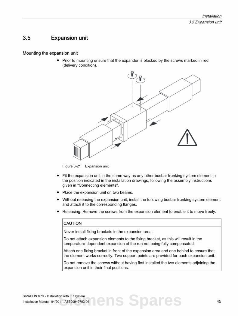
Mounting the expansion unit ● Prior to mounting ensure that the expander is blocked by the screws marked in red
(delivery condition).
Figure 3-21 Expansion unit
● Fit the expansion unit in the same way as any other busbar trunking system element in the position indicated in the installation drawings, following the assembly instructions given in "Connecting elements".
● Place the expansion unit on two beams.
● Without releasing the expansion unit, install the following busbar trunking system element and attach it to the corresponding flanges.
● Releasing: Remove the screws from the expansion element to enable it to move freely.
CAUTION
Never install fixing brackets in the expansion area.
Do not attach expansion elements to the fixing bracket, as this will result in the temperature-dependent expansion of the run not being fully compensated.
Attach one fixing bracket in front of the expansion area and one behind to ensure that the element works correctly. Two support points are provided for each expansion unit.
Do not remove the screws without having first installed the two elements adjoining the expansion unit in their final positions.
Siemens Spares

Installation 3.6 Terminal elements
SIVACON 8PS - Installation with LR system 46 Installation Manual, 04/2011, A5E00949793-01
3.6 Terminal elements The following elements are grouped under the term "terminal elements":
● Vertical terminal elements
● Horizontal terminal elements and
● Incoming cable connection unit elements
Transformer connection unit The transformer connection unit connects the busbar trunking system to external transformers, both mechanically and electrically. The mechanical connection is possible with encapsulated transformers on the transformer enclosure via the assembly flange.
However, you can also connect the transformer connection unit to other external power sources, such as distribution cabinets for low-voltage main distribution systems.
3.6.1 Storage prior to installation Take note of the following when storing the terminal elements:
1. Store the transformer connection unit in its original packaging, and use site transportation equipment (pallet, fixing devices).
2. Do not subject the terminal element to any additional mechanical loads.

Installation 3.6 Terminal elements
SIVACON 8PS - Installation with LR system Installation Manual, 04/2011, A5E00949793-01 47
3.6.2 Installation
Preparing the flanged end for connection 1. Align the distribution board mounting surface so that it is flat.
2. Prepare the cutouts.
3. Reinforce the distribution board mounting surface in accordance with the weight of the terminal element.
4. The distribution board must contain fixtures for mechanically securing the flanged end. The flanged end's own weight must be mechanically decoupled from the electrical connection (copper connection).
5. Electrical connecting lugs must be provided for the electrical connection. During this process, observe the flanged end connection dimensions and cross-section specifications, as well as the distribution board manufacturer's specifications.
Installation in the distribution board Following storage and transport to the installation location, you must first mechanically secure the flanged end in the distribution board. After that, you electrically connect the flanged end to the busbars or the circuit breaker.
Mechanically fixing the flanged end 1. The power cables of the terminal element must be mechanically fixed in the distribution
board. No additional forces must arise.
2. Attach the cover plate to the distribution board enclosure. Observe the distribution board specifications relating to the degree of protection. It may be necessary to use additional sealant in order to achieve degrees of protection higher than IP55.
Connecting the flanged end electrically 1. Remove the protective transportation devices.
2. Perform the electrical connection in accordance with the terminal element specifications and the information provided by the distribution board manufacturer. Dimension the connecting material in accordance with these specifications.
Note
You must comply with the required minimum cross-sections for the flanged end, otherwise the maximum permissible limit temperature of 130°C cannot be guaranteed.
The design of the electrical connection determines the short circuit strength.
The designer, usually the distribution board manufacturer or constructor, is responsible for the temperature and short circuit rating of the electrical connection.
Siemens Spares

Installation 3.6 Terminal elements
SIVACON 8PS - Installation with LR system 48 Installation Manual, 04/2011, A5E00949793-01
3.6.3 Positioning the connection unit above the transformer ● Always position the connection tags of the transformer connection unit over the centre of
the transformer connection tags; you may have to move the transformer to achieve this.
● Ensure that no more than 150 mm separate the connection tags of the transformer connection unit and those of the transformer.
● Only use appropriate flexible connecting material (such as flexible copper straps provided by the customer) to establish the electrical connection.
Configuration dimensions for determining the position Item Description
① Transformer connection terminal element
② Monobloc centre
a Dimension data for detailed configuration
The terminal lugs including the hole pattern are dimensioned in relation to each specific order.
An additional assembly flange for adaptation to the transformer enclosure is included for the TO and TC terminal elements.
Assembly flange for terminal elements Item Description
① Assembly flange for terminal elements
Depending on the system size, a set of flexible straps and screws is available for transformer connection. A set price is available for the bid phase. Within the scope of detailed configuration, during ordering this set is broken down into flexible straps and bolting sets (LR-FLEX*, LR-SCREW*).

Installation 3.6 Terminal elements
SIVACON 8PS - Installation with LR system Installation Manual, 04/2011, A5E00949793-01 49
3.6.4 Handling if multiple busbar runs are laid in parallel
Procedure If busbar runs are laid in parallel, you must connect multiple transformer connection units in parallel too.
1. Mechanical connection: When fixing the units above the transformer, the large amount of space required means that you must take particular note of the installation dimensions of the transformer connection units and the transformer.
2. Electrical connection: The parallel connection is carried out using additional parallel connectors. These parallel connectors must be provided by the customer. Refer to the supplied installation instructions for minimum specifications relating to the connecting surface and cross-section of the parallel connectors.
An installation engineer must inspect the external electrical and mechanical connections.
Note
It is beyond the scope of this manual to document the huge number of different on-site conditions that may arise. Therefore, we recommend that installation experts evaluate on-site conditions.
CAUTION You must follow the assembly sequence step by step in order to install multiple transformer connection units connected in parallel. The first step deals with the mechanical and the second with the electrical connection.
A Transformer connection unit B Parallel connector
Figure 3-22 Parallel connection only
Siemens Spares

Installation 3.7 Fire barrier
SIVACON 8PS - Installation with LR system 50 Installation Manual, 04/2011, A5E00949793-01
A Transformer connection unit B Parallel connector
Figure 3-23 Parallel connection plus connection to transformer
3.7 Fire barrier
3.7.1 Fire barrier regulations If the busbar run passes through a fire wall or ceiling, you must provide the run with a fire barrier. It is not permissible to mount the fire barrier via the junction (joint block).
Note
It may be necessary to attach additional fire protection notices directly at the installation site in accordance with country-specific regulations.

Installation 3.7 Fire barrier
SIVACON 8PS - Installation with LR system Installation Manual, 04/2011, A5E00949793-01 51
Structural measure
Fire resistance class S60 S90 S120
① Installation material: • Mortar • Actifoam
Installation material: • Mortar • Actifoam
Installation material: • Mortar • Actifoam
② — Bulkhead material (scope of supply): • Paint coating, four-sided • Thickness at least
1.0 mm • Length at least 200 mm
—
LR...01... to LR...29...
③ — — Bulkhead material (scope of supply): • 1 cartridge of sealing
compound • 4 panels, Promatect-200 • 20 mm thick • 200 mm long
Notes Coat the standard system on site with mortar or Actifoam. No further actions are necessary.
Coat the standard system on site with mortar or Actifoam. Additional protective coating on the left and right of the wall or ceiling
Coat the standard system on site with mortar or Actifoam. Additional Promatect-200 panels on the left and right of the wall or ceiling. Apply sealing compound to panel edges.
Structural measures apply to the fire barrier version in compliance with IEC 60439-2. Please enquire with the product area for details of additional measures for the German market in compliance with DIN 4102-9.
Special aspects of fire barrier The LR fire barrier fulfils the requirements of fire resistance classes S60, S90 and S120 in compliance with EN 60439-2. Categorisation according to the relevant fire resistance class applies to all kinds of buildings, including high-rise buildings. For use of LR fire barrier in compliance with DIN 4102-9 for the German market, you must clarify the fire barrier version in advance in the product area.
Siemens Spares

Installation 3.8 Tap-off unit
SIVACON 8PS - Installation with LR system 52 Installation Manual, 04/2011, A5E00949793-01
3.8 Tap-off unit
Tap-off units Installation of the tap-off units must be discussed with the manufacturer.

SIVACON 8PS - Installation with LR system Installation Manual, 04/2011, A5E00949793-01 53
Commissioning 44.1 Steps to be performed prior to electrification of the line
WARNING Hazardous voltage
Danger of death or serious injury! Therefore, proceed with extreme caution and follow these instructions carefully.
1. Insulate the busbar trunking system from the connections to transformers, switches, meters, etc.
2. Check that all connections are fully tightened. Follow the instructions relating to tightening torques (visual inspection with record of results).
3. Check all suspension and fixing elements. All the fixing studs and screws of the fixing brackets must be tightened.
4. Make sure that all tap-off units and tapping equipment is disconnected (OFF).
5. Carry out an insulation resistance test to make sure that there are no short circuits or earth failures in the system (phase - earth, phase - neutral and phase - phase). You will observe that the readings vary depending on the length of the run, the number and size of the conductors and the level of moisture in the atmosphere. Record the measured values in an insulation test report. If you obtain readings lower than 1 MΩ per 100 m (1 MΩ x 100/length of run in metres), please contact technical support. As a rule, you must comply with the relevant country-specific regulations (in Germany, this is a minimum of 0.5 MΩ).
6. Check that the poles on the busbar trunking system and those on the transformers, switches, meters, etc. correspond correctly on electrification.
WARNING
The following actions may only be carried out by authorised electrically skilled persons: • Establishing zero potential • Preventing the system from being switched back on • Documenting these switching operations
Siemens Spares

Commissioning 4.2 Electrifying the line
SIVACON 8PS - Installation with LR system 54 Installation Manual, 04/2011, A5E00949793-01
4.2 Electrifying the line
WARNING Hazardous voltage
Danger of death or serious injury! The first time that the busbar trunking system conductors are electrified can be dangerous. Therefore, you must follow the instructions below to the letter, along with the country-specific regulations valid in each case.
1. Qualified personnel must be present the first time the line is electrified. If short circuits or earth failures caused by incorrect installation have not been previously detected, this can lead to serious consequences once voltage is applied.
2. There must be no electrical load connected to the busbar trunking system when it is electrified; the entire system must be checked to ensure that this is the case.
3. You must electrify the line step by step, starting at the power supply and moving towards the loads at the end. The principal elements must be electrified first, followed by the feed equipment and, finally, the secondary element circuits. You must act with purpose and conviction when connecting the line.
4. Once the line has been connected, consumers such as lights, contactors, heaters and motors can be switched on.
5. Faults caused by short circuits must trigger the protective device for the feeder unit in the manner prescribed by the official regulations. You must ensure that the system is de-energised before you eliminate the cause of the fault. Observe the five safety rules: 1. Disconnect; 2. Safeguard against restart; 3. Ensure the system is de-energised; 4. Earth and short circuit; 5. Cover and safeguard neighbouring live parts.

SIVACON 8PS - Installation with LR system Installation Manual, 04/2011, A5E00949793-01 55
Service and maintenance 5
The LR busbar trunking system is maintenance-free as long as the following conditions are met:
● Assembly was performed in line with the valid guidelines as per the installation instructions and the installation manual.
● Commissioning was performed correctly and then checked and logged with insulation measurements and visual inspections.
● There are no extreme mechanical stresses/loads due to external forces.
● There are no extreme stresses/loads due to water or liquids.
● There are no extreme stresses/loads due to aggressive media.
● There are no other malfunction-based loads/stresses due to short circuits, fire or gas.
This maintenance-free claim does not include devices fitted in tap-off units, feeder units or coupling units. The instructions on their maintenance should be taken from the respective manuals/documentation supplied with the devices.
Within the scope of subsequent operational checks, the following tests are recommended:
● Visual inspections of the busbar run for external damage
● Visual inspection of the plastic membranes (neoprene seals) at the terminal elements for damage
● Checking of the customer connections (tightening torque check of the screwed mechanical connections M10 and M12 ⇒ torque specifications in accordance with DIN).
Installation and maintenance of the busbars in the EX area
NOTICE In the EX area, you must ensure that electrostatic charging of the busbar insulation is prevented by the measures below.
The measures are:
● Service and cleaning work must only be carried out when it has been ascertained that no explosive atmosphere is present. Following installation, the ATEX designation and the danger notice must be clearly visible.
● If any of the conditions listed above cannot be guaranteed, you should consult your SIEMENS contact directly.
● Please also get in touch with your SIEMENS contact for any additional inspections that have to be performed regularly for the erector and operator due to country-specific standards, regulations on accident prevention and safety, as well as for special work areas.
Siemens Spares

Service and maintenance
SIVACON 8PS - Installation with LR system 56 Installation Manual, 04/2011, A5E00949793-01
Expanding and dismantling elements of the system It may sometimes be necessary to dismantle a length of the busbar trunking system for the purposes of expansion or replacement. It is not possible to dismantle or expand LR busbar trunking systems. If necessary, contact the manufacturer.
SIVACON 8PS - Installation with LR system Installation Manual, 04/2011, A5E00949793-01 57
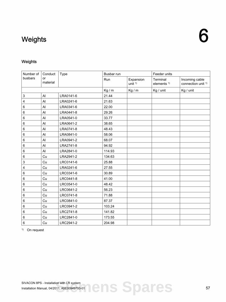
Weights 6Weights
Busbar run Feeder units Number of busbars
Conductor material
Type Run
Expansion unit 1)
Terminal elements 1)
Incoming cable connection unit 1)
Kg / m Kg / m Kg / unit Kg / unit 3 Al LRA0141-6 21.44 4 Al LRA0241-6 21.63 6 Al LRA0341-6 22.00 6 Al LRA0441-8 29.26 6 Al LRA0541-0 33.77 6 Al LRA0641-2 38.65 6 Al LRA0741-8 48.43 6 Al LRA0841-0 58.06 6 Al LRA0941-2 68.07 6 Al LRA2741-8 94.92 6 Al LRA2841-0 114.93 6 Cu LRA2941-2 134.63 3 Cu LRC0141-6 25.88 4 Cu LRA0241-6 27.55 6 Cu LRC0341-6 30.89 6 Cu LRC0441-8 41.00 6 Cu LRC0541-0 48.42 6 Cu LRC0641-2 56.23 6 Cu LRC0741-8 71.88 6 Cu LRC0841-0 87.37 6 Cu LRC0941-2 103.24 6 Cu LRC2741-8 141.82 6 Cu LRC2841-0 173.55 6 Cu LRC2941-2 204.98
1) On request
Siemens Spares

Weights
SIVACON 8PS - Installation with LR system 58 Installation Manual, 04/2011, A5E00949793-01
Busbar run Feeder units Number of
busbars Conductor material
Type Run
Expansion unit 1)
Terminal elements 1)
Incoming cable connection unit 1)
Kg / m Kg / m Kg / unit Kg / unit 3 Al LRA0151-6 21.78 4 Al LRA0251-6 22.02 6 Al LRA0351-6 22.49 6 Al LRA0451-8 34.61 6 Al LRA0551-0 40.34 6 Al LRA0651-2 45.68 6 Al LRA0751-8 57.73 6 Al LRA0851-0 69.20 6 Al LRA0951-2 81.05 6 Al LRA2751-8 113.21 6 Al LRA2851-0 137.29 6 Cu LRA2951-2 160.60 3 Cu LRC0151-6 27.33 4 Cu LRA0251-6 29.42 6 Cu LRC0351-6 33.60 6 Cu LRC0451-8 49.27 6 Cu LRC0551-0 58.66 6 Cu LRC0651-2 67.67 6 Cu LRC0751-8 87.04 6 Cu LRC0851-0 105.84 6 Cu LRC0951-2 125.02 6 Cu LRC2751-8 171.65 6 Cu LRC2851-0 210.57 6 Cu LRC2951-2 248.54
1) On request

SIVACON 8PS - Installation with LR system Installation Manual, 04/2011, A5E00949793-01 59
Test reports 7
The following test reports are available for commissioning and for service/expansion purposes:
● Test report for inspecting assembled joint blocks on initial assembly
● Test report for inspecting assembled joint blocks on subsequent assembly
● Insulation test report
Siemens Spares

Test reports 7.1 Test report for inspecting assembled joint blocks on initial assembly
SIVACON 8PS - Installation with LR system 60 Installation Manual, 04/2011, A5E00949793-01
7.1 Test report for inspecting assembled joint blocks on initial assembly
Table 7- 1 Test report - initial assembly
For inspecting assembled joint blocks on initial assemblies for SIEMENS LR busbar systems Customer: Type of installation: Contact: Site: Street: Manufacturer/Type: City/Post code: Year of manufacture: Consignment no.: Run number / designation: Date: Run length: Test starts at position no.: Drawing coord.: Date of drawing: Sheet no.:
Drawing coordinates
Position Joint block initial assembly, red control ring removed
New bolt joint(s) Other remarks Test as a whole
Place: Date: Tester's signature:

Test reports 7.2 Test report for inspecting assembled joint blocks on subsequent assembly
SIVACON 8PS - Installation with LR system Installation Manual, 04/2011, A5E00949793-01 61
7.2 Test report for inspecting assembled joint blocks on subsequent assembly
Table 7- 2 Test report - subsequent assemblies
For inspecting assembled joint blocks on subsequent assemblies for SIEMENS LR busbar systems Customer: Type of installation: Contact: Site: Street: Manufacturer/Type: City/Post code: Year of manufacture: Consignment no.: Run number / designation: Date: Run length: Test starts at position no.: Drawing coord.: Date of drawing: Sheet no.:
Drawing coordinates
Position Subsequent joint block assembly for tightness
Bolt joint(s) sealed with wax
Other remarks Test as a whole
Place: Date: Tester's signature:
Siemens Spares

Test reports 7.3 Insulation test report
SIVACON 8PS - Installation with LR system 62 Installation Manual, 04/2011, A5E00949793-01
7.3 Insulation test report
Table 7- 3 Insulation test report
For inspecting assembled joint blocks on initial assemblies for SIEMENS LR busbar systems Customer: Type of installation: Contact: Site: Street: Manufacturer/Type: City/Post code: Year of manufacture: Consignment no.: Run number / designation: Date: Run length: Meter data: Meter manufacturer: Type: Direct measuring circuit voltage: Climate data: Time: Air temperature: Humidity:
NOTICE There must be no loads connected when the insulation resistance is tested!
The insulation resistance must be at least 1 megaohm!
System design: 4-pole ❒ 5-pole ❒
Specify measured values in megohms
Plant section
N-PE L1-L2 L2-L3 L3-L1 L1-PE L2-PE L3-PE L1-N L2-N L3-N L1-PEN
L2-PEN
L3-PEN
Place: Date: Tester's signature:

SIVACON 8PS - Installation with LR system Installation Manual, 04/2011, A5E00949793-01 63
Safety data sheets 88.1 Safety data sheet demoulding agent
Siemens Spares

Safety data sheets 8.1 Safety data sheet demoulding agent
SIVACON 8PS - Installation with LR system 64 Installation Manual, 04/2011, A5E00949793-01
Page 1/6Safety Data Sheet
according to 1907/2006/EC, Article 317002.90.82 :noisiveR7002.90.82 etad gnitnirP
* 1 Identification of the substance/preparation and of the company/undertaking
· Product details
· Trade name: Chemlease® 2298· Application of the substance / the preparation Release agent
· Manufacturer/Supplier:Chem-Trend (Deutschland) GmbHGanghoferstr. 47D-82216 Maisach-GernlindenTel.: 0049 (0) 8142417-0Fax.: 0049 (0) 814215884
· Further information obtainable from:Material Compliance [email protected]
· Information in case of emergency: 0049 (0) 8142417-169
2 Hazards identification
· Hazard description:
Xn HarmfulN Dangerous for the environment
· Information concerning particular hazards for human and environment:The product has to be labelled due to the calculation procedure of the "General Classification guideline forpreparations of the EU" in the latest valid version.At long or repeated contact with skin it may cause dermatitis due to the degreasing effect of the solvent.R 10 Flammable.R 51/53 Toxic to aquatic organisms, may cause long-term adverse effects in the aquatic environment.R 65 Harmful: may cause lung damage if swallowed.R 66 Repeated exposure may cause skin dryness or cracking.R 67 Vapours may cause drowsiness and dizziness.
· Classification system:The classification is according to the latest editions of the EU-lists, and extended by company and literaturedata.
* 3 Composition/information on ingredients
· Chemical characterization· Description:
Mixture: consisting of the following components.special silicone oilssolvent (hydrocarbons)
· Dangerous components:CAS: 64742-82-1EINECS: 265-185-4
Naphtha (petroleum), hydrodesulfurized heavy(145/200)Xn, N; R 10-51/53-65-66-67
50-100%
CAS: 90622-58-5EINECS: 292-460-6
Alkanes, C11-C15-iso-Xn; R 65-66
2.5-10%
(Contd. on page 2) GB

Safety data sheets 8.1 Safety data sheet demoulding agent
SIVACON 8PS - Installation with LR system Installation Manual, 04/2011, A5E00949793-01 65
Page 2/6Safety Data Sheet
according to 1907/2006/EC, Article 317002.90.82 :noisiveR7002.90.82 etad gnitnirP
Trade name: Chemlease® 2298
(Contd. of page 1)· Additional information: For the wording of the listed risk phrases refer to section 16.
4 First-aid measures
· After inhalation: Supply fresh air; consult doctor in case of complaints.· After skin contact: Wash off with soap and plenty of water.· After eye contact:
Rinse opened eye for several minutes under running water. If symptoms persist, consult a doctor.· After swallowing: Do not induce vomiting; call for medical help immediately.· Information for doctor:· Treatment If swallowed or in case of vomiting, danger of entering the lungs.
5 Fire-fighting measures
· Suitable extinguishing agents:CO2, powder or water spray. Fight larger fires with water spray or alcohol resistant foam.
· For safety reasons unsuitable extinguishing agents: Water with full jet· Special hazards caused by the substance, its products of combustion or resulting gases:
In case of fire, the following can be released:Carbon monoxide (CO)Hydrocarbons
· Protective equipment: Do not inhale explosion gases or combustion gases.· Additional information Cool endangered receptacles with water spray.
6 Accidental release measures
· Person-related safety precautions:Ensure adequate ventilationKeep away from ignition sources.
· Measures for environmental protection: Do not allow to enter sewers/ surface or ground water.· Measures for cleaning/collecting:
Absorb with liquid-binding material (sand, diatomite, acid binders, universal binders, sawdust).Dispose of the material collected according to regulations.
* 7 Handling and storage
· Handling:· Information for safe handling: Ensure good ventilation/exhaustion at the workplace.· Information about fire - and explosion protection:
Keep ignition sources away - Do not smoke.Protect from heat.Protect against electrostatic charges.Fumes can combine with air to form an explosive mixture.
· Storage:· Requirements to be met by storerooms and receptacles:
Store in cool, dry conditions in well sealed receptacles.· Information about storage in one common storage facility: Store away from oxidizing agents.· Further information about storage conditions:
Protect from heat and direct sunlight.recommended storage period :approx. 18 months starting from date of production
GB
(Contd. on page 3)
Siemens Spares

Safety data sheets 8.1 Safety data sheet demoulding agent
SIVACON 8PS - Installation with LR system 66 Installation Manual, 04/2011, A5E00949793-01
Page 3/6Safety Data Sheetaccording to 1907/2006/EC, Article 31
7002.90.82 :noisiveR7002.90.82 etad gnitnirP
Trade name: Chemlease® 2298
(Contd. of page 2)
8 Exposure controls/personal protection
· Additional information about design of technical facilities: No further data; see item 7.
· Ingredients with limit values that require monitoring at the workplace:The product does not contain any relevant quantities of materials with critical values that have to be monitoredat the workplace.
· Additional information: The lists valid during the making were used as basis.
· Personal protective equipment:· General protective and hygienic measures:
Immediately remove all soiled and contaminated clothingDo not inhale gases / fumes / aerosols.Avoid close or long term contact with the skin.Be sure to clean skin thoroughly after work and before breaks.
· Respiratory protection: Not required.· Protection of hands: Solvent resistant gloves· Material of gloves
The selection of the suitable gloves does not only depend on the material, but also on further marks of qualityand varies from manufacturer to manufacturer. As the product is a preparation of several substances, theresistance of the glove material can not be calculated in advance and has therefore to be checked prior to theapplication.
· Penetration time of glove materialThe exact break trough time has to be found out by the manufacturer of the protective gloves and has to beobserved.
· Eye protection:
Tightly sealed goggles
9 Physical and chemical properties
· General Information
Form: FluidColour: ClearOdour: Product specific
· Change in conditionBoiling point/Boiling range: 153-198°C
· Flash point: > 40°C (DIN 51755)
· Ignition temperature: 235°C
· Danger of explosion: Product is not explosive. However, formation of explosive air/vapourmixtures are possible.
· Explosion limits:Lower: 0.67 Vol %Upper: 6.4 Vol %
· Vapour pressure at 20°C: 3 hPa
· Density at 20°C: ~ 0.85 g/cm³
· Solubility in / Miscibility withwater: Insoluble.
· Additional information: Values refer to the solvent. GB
(Contd. on page 4)

Safety data sheets 8.1 Safety data sheet demoulding agent
SIVACON 8PS - Installation with LR system Installation Manual, 04/2011, A5E00949793-01 67
Page 4/6Safety Data Sheet
according to 1907/2006/EC, Article 317002.90.82 :noisiveR7002.90.82 etad gnitnirP
Trade name: Chemlease® 2298
(Contd. of page 3)
10 Stability and reactivity
· Thermal decomposition / conditions to be avoided:No decomposition if used and stored according to specifications.
· Dangerous reactions Reacts with oxidizing agents.· Dangerous decomposition products: Carbon monoxide
11 Toxicological information
· Acute toxicity:· LD/LC50 values relevant for classification:
64742-82-1 Naphtha (petroleum), hydrodesulfurized heavy(145/200)Oral LD50 > 2000 mg/kg (rat)
· Additional toxicological information:The product shows the following dangers according to the calculation method of the General EU ClassificationGuidelines for Preparations as issued in the latest version:Harmful
* 12 Ecological information
· Ecotoxical effects:· Behaviour in sewage processing plants: The product can be mechanically separated.· General notes:
Toxic for aquatic organismsDo not allow product to reach ground water, water course or sewage system.
13 Disposal considerations
· Product:· Recommendation Can be incinerated in accordance with local and national regulations.· Waste disposal key:
For this product no waste disposal key according the European Waste Catalogue (EWC) can be determined,as only the purpose of application defined by the user enables an allocation. The waste code number has to bedetermined in accordance with the local waste disposer.
· Uncleaned packaging:· Recommendation:
Empty contaminated packagings thoroughly. They may be recycled after thorough and proper cleaning.
14 Transport information
· Land transport ADR/RID (cross-border)
· ADR/RID class: 3 Flammable liquids.· Danger code (Kemler): 30· UN-Number: 1300· Packing group: III· Hazard label 3
(Contd. on page 5) GB
Siemens Spares

Safety data sheets 8.1 Safety data sheet demoulding agent
SIVACON 8PS - Installation with LR system 68 Installation Manual, 04/2011, A5E00949793-01
Page 5/6Safety Data Sheet
according to 1907/2006/EC, Article 317002.90.82 :noisiveR7002.90.82 etad gnitnirP
Trade name: Chemlease® 2298
(Contd. of page 4)
· Description of goods: 1300 TURPENTINE SUBSTITUTE, mixture
· Maritime transport IMDG:
· IMDG Class: 3· UN Number: 1300· Label 3· Packing group: III· EMS Number: F-E,S-E· Marine pollutant: No· Proper shipping name: TURPENTINE SUBSTITUTE, solution
· Air transport ICAO-TI and IATA-DGR:
· ICAO/IATA Class: 3· UN/ID Number: 1300· Label 3· Packing group: III· Proper shipping name: Turpentine Substitute, solution
* 15 Regulatory information
· Labelling according to EU guidelines:The product has been classified and marked in accordance with EU Directives / Ordinance on HazardousMaterials.
· Code letter and hazard designation of product:
Xn HarmfulN Dangerous for the environment
· Hazard-determining components of labelling:Naphtha (petroleum), hydrodesulfurized heavy(145/200)
· Risk phrases:10 Flammable.51/53 Toxic to aquatic organisms, may cause long-term adverse effects in the aquatic environment.65 Harmful: may cause lung damage if swallowed.66 Repeated exposure may cause skin dryness or cracking.67 Vapours may cause drowsiness and dizziness.
· Safety phrases:16 Keep away from sources of ignition - No smoking.23 Do not breathe fumes.33 Take precautionary measures against static discharges.51 Use only in well-ventilated areas.61 Avoid release to the environment. Refer to special instructions/safety data sheets.62 If swallowed, do not induce vomiting: seek medical advice immediately and show this container or label.
(Contd. on page 6) GB

Safety data sheets 8.1 Safety data sheet demoulding agent
SIVACON 8PS - Installation with LR system Installation Manual, 04/2011, A5E00949793-01 69
Page 6/6Safety Data Sheet
according to 1907/2006/EC, Article 317002.90.82 :noisiveR7002.90.82 etad gnitnirP
Trade name: Chemlease® 2298
(Contd. of page 5)
· National regulations:
· Information about limitation of use: Employment restrictions concerning juveniles must be observed.
16 Other informationThis information is based on our present knowledge. However, this shall not constitute a guarantee for anyspecific product features and shall not establish a legally valid contractual relationship.
· Relevant R-phrases10 Flammable.51/53 Toxic to aquatic organisms, may cause long-term adverse effects in the aquatic environment.65 Harmful: may cause lung damage if swallowed.66 Repeated exposure may cause skin dryness or cracking.67 Vapours may cause drowsiness and dizziness.
· Department issuing MSDS: Material Compliance Management (MCM)· Contact: Tel.: +49 (0) 8142417-136· * Data compared to the previous version altered.
GB
Siemens Spares

Safety data sheets 8.2 Safety data sheet BKS 1 epoxy resin mix
SIVACON 8PS - Installation with LR system 70 Installation Manual, 04/2011, A5E00949793-01
8.2 Safety data sheet BKS 1 epoxy resin mix
SAFETY DATA SHEET according to EC directive 93/112/EC
MISCHUNG BKS 1Version 2 Print Date 03.11.2009Revision Date: 03.11.2009
1/8
1. IDENTIFICATION OF THE SUBSTANCE/PREPARATION AND THE COMPANY/UNDERTAKING
Product information
Trade name : BK S Resin Comp.A
Use : Component used for the manufacture of electricial insulation parts.
Company : ASTORit AGKobiboden 48840 Einsiedeln
Telephone : +41554187500Telefax : +41554187501Emergency telephone number
: +41442515151
Fur further Product EHS related questions concerning this document or its contents, please contact: E-mail: [email protected]
2. COMPOSITION/INFORMATION ON INGREDIENTS
Chemical nature
Bisphenol A epoxy resin containing reactive diluentpreparation
Hazardous components
Chemical Name CAS-No. Symbol(s): R-phrase(s) Concentration [%]reaction product: bisphenol A-(epichlorhydrin); epoxy resin (number average molecular weight < 700)
25068-38-6
Xi, N R36/38 R43 R51/53 70.00 - 82.00
o-cresyl glycidyletherEG-Nr.:218-645-3
2210-79-9 Xn, N R38 R43 R51/53 R68 22.00 - 30.00
3. HAZARDS IDENTIFICATION
Irritating to eyes and skin.Possible risks of irreversible effects.May cause sensitization by skin contact.Toxic to aquatic organisms, may cause long-term adverse effects in the aquatic environment.
4. FIRST AID MEASURES
Inhalation : Move to fresh air.Oxygen or artificial respiration if needed.Call a physician immediately.

Safety data sheets 8.2 Safety data sheet BKS 1 epoxy resin mix
SIVACON 8PS - Installation with LR system Installation Manual, 04/2011, A5E00949793-01 71
SAFETY DATA SHEET according to EC directive 93/112/EC
MISCHUNG BKS 1Version 2 Print Date 03.11.2009Revision Date: 03.11.2009
2/8
Eye contact : Rinse immediately with plenty of water for at least 15 minutes.Call a physician immediately.
Skin contact : Clean with detergents. Avoid solvents.
Ingestion : Immediately give plenty of water (if possible charcoal slurry).If a person vomits when lying on his back, place him in the recovery position.Oxygen or artificial respiration if needed.Do not induce vomiting.
5. FIRE-FIGHTING MEASURES
Suitable extinguishing media
: Water spray.Carbon dioxide (CO2).Foam.Dry powder.
Extinguishing media which must not be used for safety reasons
: High volume water jet.
Special protective equipment for fire-fighters
: Wear self-contained breathing apparatus and protective suit.
Further information : Burning produces obnoxious and toxic fumes.Carbon oxides.
6. ACCIDENTAL RELEASE MEASURES
Personal precautions : Keep away from sources of ignition - No smoking.Avoid contact with skin, eyes and clothing.Do not breathe vapours/dust.
Environmental precautions : Prevent product from entering drains.Do not contaminate surface water.Avoid subsoil penetration.
Methods for cleaning up : Soak up with inert absorbent material and dispose of as hazardous waste.
7. HANDLING AND STORAGE
Handling
Advice on safe handling : Provide sufficient air exchange and/or exhaust in work rooms.Avoid formation of aerosol.Ensure adequate ventilation.Handle and open container with care.
Storage
Siemens Spares

Safety data sheets 8.2 Safety data sheet BKS 1 epoxy resin mix
SIVACON 8PS - Installation with LR system 72 Installation Manual, 04/2011, A5E00949793-01
SAFETY DATA SHEET according to EC directive 93/112/EC
MISCHUNG BKS 1Version 2 Print Date 03.11.2009Revision Date: 03.11.2009
3/8
Further information on storage conditions
: Keep away from food, drink and animal feeding stuffs.Keep container tightly closed.Keep at temperatures between 2 and 40°C.
Storage hazard class : Storage class 10, Environmentally hazardous liquids
8. EXPOSURE CONTROLS / PERSONAL PROTECTIONComponents with workplace control parameters
Components CAS-No. Controlparameters
Update Basis
o-cresyl glycidylether 2210-79-9 70 mg/m3140 mg/m3
AT-MAK 8HAT-MAK 15M
Engineering measures
No special precautions required.
Personal protective equipment
Respiratory protection : In case of insufficient ventilation wear suitable respiratory equipment.
Eye protection : Tightly fitting safety goggles.Face-shield.
Hand protection : Material of gloves for long term application (BTT>480 min):Butyl rubberEthyl Vinyl Alcohol Laminate (EVAL)Nitrile rubberNeoprene rubberPolyvinyl Chloride (PVC)Material of gloves for short term/splash application (10 min<BTT<480 min):Butyl rubberEthyl Vinyl Alcohol Laminate (EVAL)Nitrile rubberNeoprene rubberPolyvinyl Chloride (PVC)Use gloves approved to relevant standards e.g. EN 374 (Europe), F739 (US).Suitability and durability of a glove is dependent on usage, e.g. frequency and duration of contact, chemical resistance of glove material and dexterity. Always seek advice from glove suppliers.Additonal information can be found for instance at www.sapros.ch
Hand protection :Skin and body protection : Protective suit.
Safety shoes.
Protective measures : Keep away from sources of ignition - No smoking.Avoid contact with skin, eyes and clothing.

Safety data sheets 8.2 Safety data sheet BKS 1 epoxy resin mix
SIVACON 8PS - Installation with LR system Installation Manual, 04/2011, A5E00949793-01 73
SAFETY DATA SHEET according to EC directive 93/112/EC
MISCHUNG BKS 1Version 2 Print Date 03.11.2009Revision Date: 03.11.2009
4/8
9. PHYSICAL AND CHEMICAL PROPERTIES
Form : liquid
Colour : clear
Odour : slight
Boiling point : > 200 °C
Thermal decomposition : > 200 °C
Flash point : 138 °CMethod: DIN 51758 (Pensky-Martens Closed Cup)
Vapour pressure : 1 Paat 20 °C
Density : 1.15 g/cm3at 20 °C
Water solubility : at 20 °CNote: practically insoluble
Miscibility with water : immiscible
Viscosity, dynamic : 500 - 650 mPa.sat 25 °C
10. STABILITY AND REACTIVITY
Conditions to avoid : Note: Take necessary action to avoid static electricity discharge.
Materials to avoid : Strong acids and strong bases.Strong oxidizing agents.
Hazardous decomposition products
: Carbon oxides. Burning produces obnoxious and toxic fumes.
11. TOXICOLOGICAL INFORMATION
Acute oral toxicity : LD50 ratDose: > 5,000 mg/kg
Eye irritation : irritatingrabbit
Skin irritation : irritatingrabbitdermal
Siemens Spares

Safety data sheets 8.2 Safety data sheet BKS 1 epoxy resin mix
SIVACON 8PS - Installation with LR system 74 Installation Manual, 04/2011, A5E00949793-01
SAFETY DATA SHEET according to EC directive 93/112/EC
MISCHUNG BKS 1Version 2 Print Date 03.11.2009Revision Date: 03.11.2009
5/8
Sensitization : Causes sensitization.guinea pigdermal
Further information : o-CGE is a direct-acting mutagen in in-vitro test systems. Studies in vivo, including micronucleus tests and assays in transgenic animals, showed no mutagenic activity.
12. ECOLOGICAL INFORMATIONEcotoxicity effects
Further information on ecology
Additional ecological information
: Avoid subsoil penetration.Prevent product from entering drains.Do not contaminate surface water.
13. DISPOSAL CONSIDERATIONS
Product : Must be incinerated, when in compliance with local regulations.
Container : Empty containers can be landfilled after cleaning, when in compliance with the Environmental Protection.
Contaminated packaging : Waste Key Number: 070208
14. TRANSPORT INFORMATION
Land transport
ADR:
UN-No: 3082Class: 9Packaging Group IIIRisk No.: 90ADR/RID-Labels: 9Proper shipping name: ENVIRONMENTALLY HAZARDOUS SUBSTANCE, LIQUID,
N.O.S.contains: BISPHENOL A EPOXY RESINcontains: 1,2-CRESYL GLYCIDYL ETHER
RID:
UN-No: 3082Class: 9Packaging Group IIIRisk No.: 90ADR/RID-Labels: 9Proper shipping name: ENVIRONMENTALLY HAZARDOUS SUBSTANCE, LIQUID,

Safety data sheets 8.2 Safety data sheet BKS 1 epoxy resin mix
SIVACON 8PS - Installation with LR system Installation Manual, 04/2011, A5E00949793-01 75
SAFETY DATA SHEET according to EC directive 93/112/EC
MISCHUNG BKS 1Version 2 Print Date 03.11.2009Revision Date: 03.11.2009
6/8
N.O.S.contains: BISPHENOL A EPOXY RESINcontains: 1,2-CRESYL GLYCIDYL ETHER
Sea transport
IMDG:
UN-No: 3082Class: 9Packaging Group IIIRisk No.: 90ADR/RID-Labels: 9Proper shipping name: ENVIRONMENTALLY HAZARDOUS SUBSTANCE, LIQUID,
N.O.S.EmS F-A-S-Fcontains: BISPHENOL A EPOXY RESINcontains: 1,2-CRESYL GLYCIDYL ETHER
Air transport
IATA-DGR:
UN/ID No.: UN 3082Class: 9Packaging group: IIIPacking instruction (cargo aircraft):
914
ADR/RID-Labels: 9Proper shipping name: ENVIRONMENTALLY HAZARDOUS SUBSTANCE, LIQUID,
N.O.S.contains: (BISPHENOL A EPOXY RESIN)contains: (1,2-CRESYL GLYCIDYL ETHER)
15. REGULATORY INFORMATIONLabelling according to EEC Directive
Labelling required
Symbol(s): : Xn HarmfulN Dangerous for the environment
R-phrase(s) : R36/38 Irritating to eyes and skin.R68 Possible risks of irreversible effects.R43 May cause sensitization by skin contact.R51/53 Toxic to aquatic organisms, may cause
long-term adverse effects in the aquatic environment.
S-phrase(s) : S28 After contact with skin, wash immediately with plenty of soap and water.
S37/39 Wear suitable gloves and eye/face
Siemens Spares
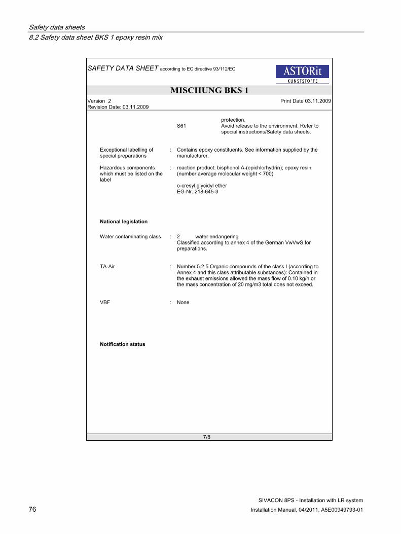
Safety data sheets 8.2 Safety data sheet BKS 1 epoxy resin mix
SIVACON 8PS - Installation with LR system 76 Installation Manual, 04/2011, A5E00949793-01
SAFETY DATA SHEET according to EC directive 93/112/EC
MISCHUNG BKS 1Version 2 Print Date 03.11.2009Revision Date: 03.11.2009
7/8
protection.S61 Avoid release to the environment. Refer to
special instructions/Safety data sheets.
Exceptional labelling of special preparations
: Contains epoxy constituents. See information supplied by the manufacturer.
Hazardous components which must be listed on the label
: reaction product: bisphenol A-(epichlorhydrin); epoxy resin (number average molecular weight < 700)
o-cresyl glycidyl etherEG-Nr.:218-645-3
National legislation
Water contaminating class : 2 water endangeringClassified according to annex 4 of the German VwVwS for preparations.
TA-Air : Number 5.2.5 Organic compounds of the class I (according toAnnex 4 and this class attributable substances): Contained in the exhaust emissions allowed the mass flow of 0.10 kg/h or the mass concentration of 20 mg/m3 total does not exceed.
VBF : None
Notification status

Safety data sheets 8.2 Safety data sheet BKS 1 epoxy resin mix
SIVACON 8PS - Installation with LR system Installation Manual, 04/2011, A5E00949793-01 77
SAFETY DATA SHEET according to EC directive 93/112/EC
MISCHUNG BKS 1Version 2 Print Date 03.11.2009Revision Date: 03.11.2009
8/8
16. OTHER INFORMATION
List of R-phrases (Section 2)
R36/38 Irritating to eyes and skin.R38 Irritating to eyesR43 May cause sensitization by skin contact.R51/53 Toxic to aquatic organisms, may cause long-term adverse effects in the
aquatic environment.R68 Possible risks of irreversible effects
All information is based on results gained from experience and tests and is believed to be accurate but is given without acceptance of liability for loss or damage attributable to reliance thereon as conditions of use lie outside our control. Users should always carry out sufficient tests to establish the suitability of any products for their intended applications. No statements shall be incorporated in any contract unless expressly agreed in writing nor construed as recommending the use of any product in conflict of any patent.
Siemens Spares

Safety data sheets 8.3 Safety data sheet BKS 2 mix
SIVACON 8PS - Installation with LR system 78 Installation Manual, 04/2011, A5E00949793-01
8.3 Safety data sheet BKS 2 mix
SAFETY DATA SHEET according to EC directive 93/112/EC
Mischung BKS 2Version 2 Print Date 03.11.2009Revision Date 03.11.2009
1/7
1. IDENTIFICATION OF THE SUBSTANCE/PREPARATION AND THE COMPANY/UNDERTAKING
Product information
Trade name : BK S Hardener Comp.B
Use : Component used for the manufacture of electricial insulation parts.
Company : ASTORit AGKobiboden 48840 Einsiedeln
Telephone : +41554187500Telefax : +41554187501Emergency telephone number
: +41442515151
Fur further Product EHS related questions concerning this document or its contents, please contact: E-mail: [email protected]
2. HAZARDS IDENTIFICATIONHarmful if swallowed.Causes burns.May cause sensitization by skin contact.Possible risk of impaired fertility.Harmful to aquatic organisms, may cause long-term adverse effects in the aquatic environment.
3. COMPOSITION/INFORMATION ON INGREDIENTSChemical nature
PolyaminoamideModified aliphatic polyaminepreparation
Hazardous components
Chemical Name CAS-No. Symbol(s): R-phrase(s) Concentration [%]4,4'-isopropylidenediphenolEG-Nr.: 201-245-8
80-05-7 Xn R37 R41 R43 R62 1.00 - 4.00
diethylenetriamineEG-Nr.: 203-865-4
111-40-0 C R21/22 R34 R43 4.00 - 8.00
triethylenetetramineEG-Nr.: 203-950-6
112-24-3 C R21 R34 R43 R52/53 1.00 - 4.00
trimethylhexamethylenediamine EC-No.: 247-134-8
25620-58-0
C R22 R34 R43 R52/53 >= 40.00 - <=46.00
4. FIRST AID MEASURESInhalation : Move to fresh air.
If symptoms persist, call a physician.

Safety data sheets 8.3 Safety data sheet BKS 2 mix
SIVACON 8PS - Installation with LR system Installation Manual, 04/2011, A5E00949793-01 79
SAFETY DATA SHEET according to EC directive 93/112/EC
Mischung BKS 2Version 2 Print Date 03.11.2009Revision Date 03.11.2009
2/7
Eye contact : Rinse immediately with plenty of water for at least 15 minutes.Call a physician immediately.
Skin contact : Wash off immediately with soap and plenty of water removing all contaminated clothes and shoes.If skin irritation persists, call a physician.Clean with detergents. Avoid solvents.
Ingestion : Immediately give plenty of water (if possible charcoal slurry).If a person vomits when lying on his back, place him in the recovery position.Oxygen or artificial respiration if needed.Do not induce vomiting.
5. FIRE-FIGHTING MEASURES
Suitable extinguishing media
: Water spray.Carbon dioxide (CO2).Foam.Dry powder.
Extinguishing media which must not be used for safety reasons
: High volume water jet.
Special protective equipment for fire-fighters
: Wear self-contained breathing apparatus and protective suit.
Further information : Burning produces obnoxious and toxic fumes.Carbon oxides.Nitrogen oxides.
6. ACCIDENTAL RELEASE MEASURES
Personal precautions : Keep away from sources of ignition - No smoking.Avoid contact with skin, eyes and clothing.Do not breathe vapours/dust.
Environmental precautions : Prevent product from entering drains.Do not contaminate surface water.Avoid subsoil penetration.
Methods for cleaning up : Soak up with inert absorbent material and dispose of as hazardous waste.
7. HANDLING AND STORAGE
Handling
Advice on safe handling : Provide sufficient air exchange and/or exhaust in work rooms.sensitizing
Siemens Spares

Safety data sheets 8.3 Safety data sheet BKS 2 mix
SIVACON 8PS - Installation with LR system 80 Installation Manual, 04/2011, A5E00949793-01
SAFETY DATA SHEET according to EC directive 93/112/EC
Mischung BKS 2Version 2 Print Date 03.11.2009Revision Date 03.11.2009
3/7
Avoid formation of aerosol.Ensure adequate ventilation.Handle and open container with care.Keep away from sources of ignition - No smoking.
Storage
Further information on storage conditions
: Keep away from food, drink and animal feeding stuffs.Keep container tightly closed.Store at room temperature in the original container.
Storage hazard class : Storage class 8, Corrosive substances
8. EXPOSURE CONTROLS / PERSONAL PROTECTION
Components with workplace control parameters
Components CAS-No. Controlparameters
Update Basis
diethylenetriamine 111-40-0 4 mg/m3 CH-MAK 8H
Engineering measures
Provide appropriate exhaust ventilation at machinery and at places where dust can be generated.
Personal protective equipment
Respiratory protection : In case of insufficient ventilation wear suitable respiratory equipment.Filter type AX-P2 (organic vapours, particles)
Eye protection : Tightly fitting safety goggles.Face-shield.
Hand protection : Material of gloves for long term application (BTT>480 min):Butyl rubberEthyl Vinyl Alcohol Laminate (EVAL)Material of gloves for short term/splash application (10 min<BTT<480 min):Nitrile rubberUse gloves approved to relevant standards e.g. EN 374 (Europe), F739 (US).Suitability and durability of a glove is dependent on usage, e.g. frequency and duration of contact, chemical resistance of glove material and dexterity. Always seek advice from glove suppliers.Additonal information can be found for instance at www.sapros.ch
Skin and body protection : Protective suit.Safety shoes.
Protective measures : Do not breathe vapours/dust.Keep away from sources of ignition - No smoking.

Safety data sheets 8.3 Safety data sheet BKS 2 mix
SIVACON 8PS - Installation with LR system Installation Manual, 04/2011, A5E00949793-01 81
SAFETY DATA SHEET according to EC directive 93/112/EC
Mischung BKS 2Version 2 Print Date 03.11.2009Revision Date 03.11.2009
4/7
Avoid contact with skin, eyes and clothing.
9. PHYSICAL AND CHEMICAL PROPERTIES
Form : liquid
Colour : brownclear
Odour : amine-like
pH : approx. 11at (20 °C)1:1 in water
Boiling point : > 200 °C
Thermal decomposition : > 200 °C
Flash point : 112 °CMethod: DIN 51758 (Pensky-Martens Closed Cup)
Vapour pressure : < 4 Paat 20 °C
Density : 0.99 g/cm3at 25 °C
Water solubility : at 20 °CNote: partly miscible
Miscibility with water : miscible
Viscosity, dynamic : 500 - 900 mPa.sat 25 °C
10. STABILITY AND REACTIVITY
Conditions to avoid : Note: Take necessary action to avoid static electricity discharge.
Materials to avoid : Strong acids and strong bases.Strong oxidizing agents.
Hazardous decomposition products
: Carbon oxides. Burning produces obnoxious and toxic fumes.
Nitrogen oxides. Burning produces obnoxious and toxic fumes.
11. TOXICOLOGICAL INFORMATION
Acute oral toxicity : LD50 rat
Siemens Spares

Safety data sheets 8.3 Safety data sheet BKS 2 mix
SIVACON 8PS - Installation with LR system 82 Installation Manual, 04/2011, A5E00949793-01
SAFETY DATA SHEET according to EC directive 93/112/EC
Mischung BKS 2Version 2 Print Date 03.11.2009Revision Date 03.11.2009
5/7
Dose: 2,800 mg/kg
Eye irritation : Corrosiverabbit
Skin irritation : Corrosiverabbitdermal
Sensitization : Causes sensitization.guinea pigdermal
12. ECOLOGICAL INFORMATION
Ecotoxicity effects
Further information on ecology
Additional ecological information
: Avoid subsoil penetration.Prevent product from entering drains.Do not contaminate surface water.
13. DISPOSAL CONSIDERATIONS
Product : Must be incinerated, when in compliance with local regulations.
Container : Empty containers can be landfilled after cleaning, when in compliance with the Environmental Protection.
14. TRANSPORT INFORMATION
Land transport
ADR:
UN-No: 2327Class: 8Classification code: C7Packaging group: IIIRisk No.: 80ADR/RID-Labels: 8Proper shipping name: TRIMETHYLHEXAMETHYLENEDIAMINE SOLUTIONcontain: DIETHYLENE TRIAMINEcontain: TRIETHYLENE TETRAMINE
RID:
UN-No: 2327

Safety data sheets 8.3 Safety data sheet BKS 2 mix
SIVACON 8PS - Installation with LR system Installation Manual, 04/2011, A5E00949793-01 83
SAFETY DATA SHEET according to EC directive 93/112/EC
Mischung BKS 2Version 2 Print Date 03.11.2009Revision Date 03.11.2009
6/7
Class: 8Packaging group: IIIRisk No.: 80ADR/RID-Labels: 8Proper shipping name: TRIMETHYLHEXAMETHYLENEDIAMINE SOLUTIONcontain: DIETHYLENE TRIAMINEcontain: TRIETHYLENE TETRAMINE
Sea transport
IMDG:
UN-No: 2327Class: 8Packaging group: IIIADR/RID-Labels: 8MFAG:EmS: F-A S-BProper shipping name: TRIMETHYLHEXAMETHYLENEDIAMINE SOLUTIONcontain: (DIETHYLENE TRIAMINE)contain: (TRIETHYLENE TETRAMINE)
Air transport
IATA-DGR:
UN/ID No.: 2327Class: 8Packaging group: IIIPacking instruction (cargo aircraft):
820
Max. Qty/Pack.: 60.00 L.Packing instruction (passenger aircraft):
818
Max. Qty/Pack.: 5.00 LADR/RID-Labels: 8Proper shipping name: TRIMETHYLHEXAMETHYLENEDIAMINE SOLUTIONcontain: (DIETHYLENE TRIAMINE)contain: (TRIETHYLENE TETRAMINE)
15. REGULATORY INFORMATIONLabelling according to EEC Directive
Labelling required
Symbol(s): : C Corrosive
R-phrase(s) : R34 Causes burns.R22 Harmful if swallowed.R43 May cause sensitization by skin contact.R52/53 Harmful to aquatic organisms, may cause
long-term adverse effects in the aquaticenvironment.
Siemens Spares

Safety data sheets 8.3 Safety data sheet BKS 2 mix
SIVACON 8PS - Installation with LR system 84 Installation Manual, 04/2011, A5E00949793-01
SAFETY DATA SHEET according to EC directive 93/112/EC
Mischung BKS 2Version 2 Print Date 03.11.2009Revision Date 03.11.2009
7/7
R62 Possible risk of impaired fertility.
S-phrase(s) : S24/25 Avoid contact with eyes and skin.S26 In case of contact with eyes, rinse
immediately with plenty of water and seek medical advice.
S36/37/39 Wear suitable protective clothing, gloves and eye/face protection.
S45 In case of accident or if you feel unwell, seek medical advice immediately (show label where possible).
Hazardous components which must be listed on the label
: 4,4'-isopropylidenediphenolEG-Nr.: 201-245-8
DiethylenetriamineEG-Nr.: 203-865-4
trimethylhexamethylenediamineEC-No.: 247-134-8
National legislation
Water contaminating class : 2 water endangering(self-assessment)
Notification status
16. OTHER INFORMATION
R21 Harmful in contact with skin.R21/22 Harmful in contact with skin and if swallowedR34 Causes burns.R37 Irritating to respiratory systemR41 Risk of serious damage to eyesR43 May cause sensitization by skin contact.R52/53 Harmful to aquatic organisms, may cause long-term adverse effects in the
aquatic environment.R62 Possible risk of impaired fertility
All information is based on results gained from experience and tests and is believed to be accurate but is given without acceptance of liability for loss or damage attributable to reliance thereon as conditions of use lie outside our control. Users should always carry out sufficient tests to establish the suitability of any products for their intended applications. No statements shall be incorporated in any contract unless expressly agreed in writing nor construed as recommending the use of any product in conflict of any patent.

SIVACON 8PS - Installation with LR system Installation Manual, 04/2011, A5E00949793-01 85
Index
A Application planning, 7
Handling, 12 Packaging, 11 Receiving goods, 7 Safety, 8 Scope of delivery, 7 Storage, 9
B Busbar runs
Laying in parallel, 49
C Cast resin mix
Filling, 44 Mixing, 43
Casting moulds Preparing, 41
Ceiling bracket, 26 Attaching, 28
Cleaning agent, 18 Commissioning, 53
Electrifying the line, 54 Connecting units, 38 Connection, 40
Electrical, 40
D Dismantling
Elements, 56
E Electrical connection, 40
Checking, 44 Elements
Dismantling, 56 Expanding, 56
EX area, 55
Expansion Elements, 56
Expansion unit Mounting, 45
F Fire barrier
Regulations, 50 Special aspects, 51
Fixed points Vertical installation, 36
Fixing Attaching, 25
Floor fixing Vertical installation, 35
I Initial assembly
Test report, 60 Installation
Busbar run, 22 Casting moulds, 41 Ceiling bracket, 26 Cleaning agent, 18 Connecting units, 38 Demoulding agent, 18 Fixing, 25 Floor fixing, 35 Recommendations, 23 Tap-off units, 52 Types of fixing material, 25 Wall bracket, 27
Insulation test report, 62
L Laying in parallel
Busbar runs, 49 line
Electrifying, 54
M Maintenance, 55
Siemens Spares

Index
SIVACON 8PS - Installation with LR system 86 Installation Manual, 04/2011, A5E00949793-01
P Packaging, 11
R Receiving goods, 7 Regulations
Fire barrier, 50
S Safety
Handling, 8 Required measures, 8
Scope of delivery, 7 Service, 55 Storage, 9
Terminal elements, 46 Subsequent assembly
Test report, 61
T Tap-off units, 52 Terminal elements, 46
Connecting the flanged end electrically, 47 Installation, 47 Mechanically fixing the flanged end, 47 Positioning, 48 Storage, 46
Test report, 59 Initial assembly, 60 Insulation test report, 62 Subsequent assembly, 61
Transformer connection unit Terminal elements, 46
Types of fixing material, 25
V Vertical installation
Fixed points, 36
W Wall bracket, 27
Vertical installation, 31 Weights, 57
X XE \* MERGEFORMAT, 15, 18

Service & Support
Download catalogs and information material: www.siemens.com/lowvoltage/infomaterial
Newsletter – always up to date:www.siemens.com/lowvoltage/newsletter
E-business in the Industry Mall:www.siemens.com/lowvoltage/mall
Online Support:www.siemens.com/lowvoltage/support
Contact for all technical information: Technical Support www.siemens.com/lowvoltage/technical-support
www.siemens.com/lowvoltage
Subject to change without prior noticeBestell-Nr.: A5E00949793-02 © Siemens AG 2011
Siemens AGInfrastructure & Cities SectorLow and Medium Voltage DivisionLow Voltage DistributionPostfach 10 09 5393009 RegensburgGERMANY


