SIVACON 8PS Busbar Trunking Systems - Siemens · 15 SIVACON 8PS Busbar Trunking Systems...
44
Siemens LV 10.2 · 2011 15 15 Introduction 1) 15/2 Introduction 15/6 Technical overview 15/8 Principles of busbar trunking planning CD-L System – 25 ... 40 A 1) 15/9 Introduction 15/11 Trunking units 15/17 Feeder units 15/21 End flanges 15/23 Junction units 15/25 Tap-off plugs 15/29 Accessories BD01 System – 40 ... 160 A 1) 15/31 Introduction 15/32 Trunking units 15/33 Junction units, feeder units 15/34 Tap-off units for international use 15/40 Ancillary equipment units for international use 15/42 Accessories 1) Additional information in Catalog LV 70. SIVACON 8PS Busbar Trunking Systems © Siemens AG 2010
Transcript of SIVACON 8PS Busbar Trunking Systems - Siemens · 15 SIVACON 8PS Busbar Trunking Systems...

Siemens LV 10.2 · 2011
15
15
Introduction1) 15/2 Introduction15/6 Technical overview15/8 Principles of busbar trunking
planning
CD-L System – 25 ... 40 A1) 15/9 Introduction 15/11 Trunking units 15/17 Feeder units 15/21 End flanges 15/23 Junction units 15/25 Tap-off plugs 15/29 Accessories
BD01 System – 40 ... 160 A1) 15/31 Introduction 15/32 Trunking units 15/33 Junction units, feeder units 15/34 Tap-off units for international use 15/40 Ancillary equipment units for
international use 15/42 Accessories
1) Additional information in Catalog LV 70.
SIVACON 8PS Busbar Trunking Systems
LV10-2_15_EN.book Seite 1 Mittwoch, 24. November 2010 11:06 11
© Siemens AG 2010
SIVACON 8PS Busbar Trunking Systems
Introduction
15/2 Siemens LV 10.2 · 2011
15
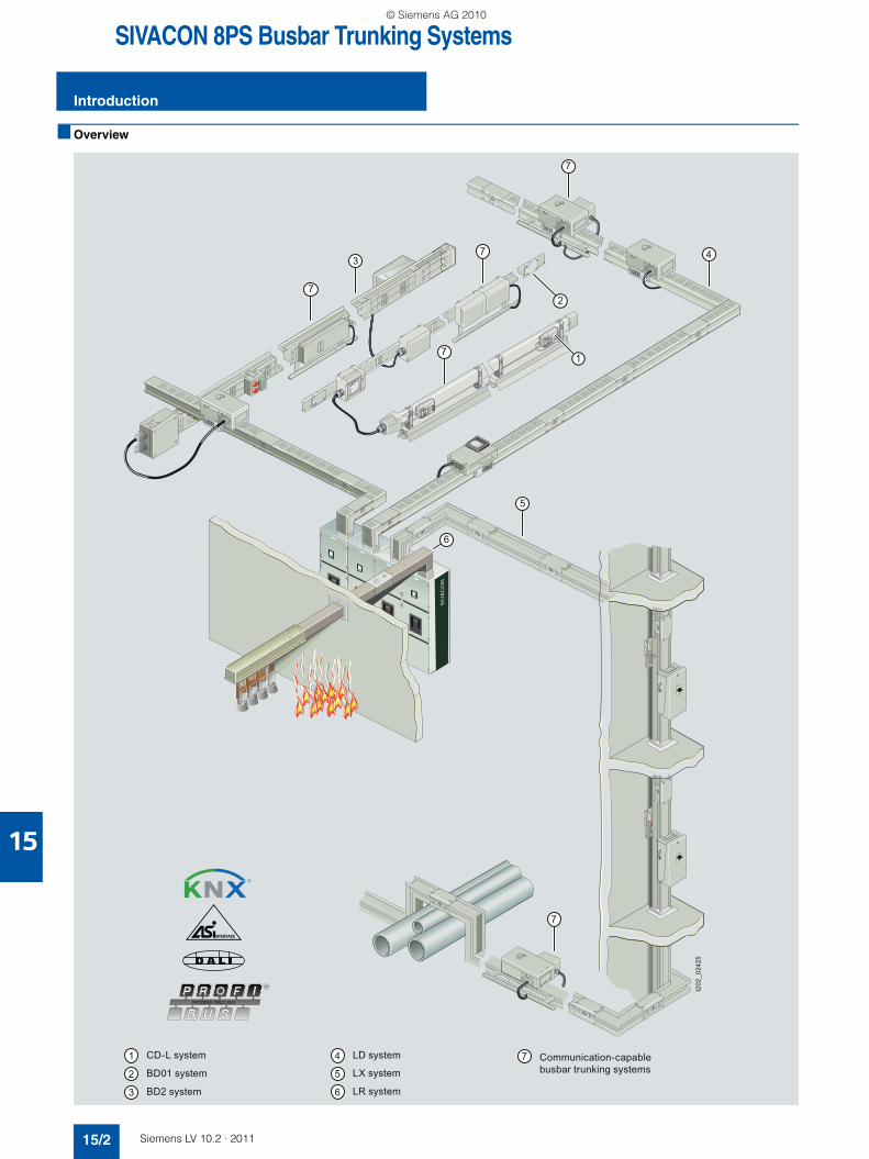
■ Overview
10DB
DB
BK-
10
-1
0D
B
BK
I202
_024
25
7
7
7
7
4
5
6
3
2
17
CD-L system
BD01 system
BD2 system
LX system
LD system
LR system
Communication-capable busbar trunking systems
LV10-2_15_EN.book Seite 2 Mittwoch, 24. November 2010 11:06 11
© Siemens AG 2010

15
SIVACON 8PS Busbar Trunking Systems
Introduction
15/3Siemens LV 10.2 · 2011
■ Benefits
$ CD-L system up to 40A
The versatile busbar trunking system for area-wide power distri-bution to lighting systems:• Versatile thanks to high degree of protection IP55• Lower planning costs through simple configuration• Time-saving mounting through plug-in quick connector• Variable changes of direction• Optimum utilization of the busbar line through tap-off points fit-
ted to both sides• Uniform current loading of the conductors through splitting of
the subsequent tap-off plugs among the individual phases• Tap-off plugs allow fast and flexible load relocation• Expandable functionality through DALI bus transmission
directly via the busbar conductors (other bus systems on request)
% BD01 system up to 160A
The busbar trunking system for power distribution in the skilled trades and business:• Degree of protection IP50, IP54, IP55 • Flexible power supply• Easy and quick planning• Time-saving mounting• Reliable mechanical and electrical connection technology• High stability, low weight• Few basic modules required• Storage-friendly system• Variable changes of direction• Versatile tap-off units• Positive opening and closing of tap-off points
& BD2 system up to 1250 A
The busbar trunking system for operation in the harsh industrial world:• Degree of protection IP52, IP54, IP55 • Easy and quick planning• Time-saving and economical mounting• Reliable and safe operation• Flexible modular system with simple solutions for every appli-
cation• Early planning of the power distribution system without exact
knowledge of load locations• Early readiness for operation thanks to fast and simple mount-
ing• Innovative design: No more compensation boxes to compen-
sate elongation.• Codable tap-off units and tap-off points• Sealable throughout
( LD system up to 5000 A
The busbar trunking system for optimized power distribution in industry:• Quick and easy mounting• Reliable and safe operation• Space-saving, compact design up to 5000 A in one enclosure• Load outgoing feeders up to 1250 A• Type-tested connection to distribution boards and transform-
ers
) LX system up to 6300 A
The busbar trunking system for power conveyance and distribu-tion in buildings:• Quick and easy mounting• Reliable and safe operation• Load outgoing feeders up to 1250 A• Type-tested connection to distribution boards and transform-
ers
* LR system up to 6150 A
The busbar trunking system for power conveyance under extreme ambient conditions (IP68).
Detailed information about this system is available from the Siemens branch located close to you.
+ Communication-capable busbar trunking systems
Communication-capable function expansions for combination with known tap-off units:• Can be used with the BD01, BD2, LD and LX systems• Uses:
- Lighting control for large areas- Remote switching and signaling in the industrial sector- consumption recording of decentral power tap-off units
• Connection to the bus systems KNX (EIB/Instabus), AS-Interface and PROFIBUS
• Easy contacting of the bus cable by insulation piercing method
• Easy and quick planning• Flexible expansions and modifications• Module system• Retrofitting of existing installations
■ More information
Catalog LV 70 - Busbar Trunking Systems CD-L, BD01, BD2 up to 1250 A
German: Order No. E86060-K1870-A101-A4 Englisch: Order No. E86060-K1870-A101-A4-7600
Selection aid for busbar trunking systems (MobileSpice)
Busway systems up to 1250 A can be ordered using the selec-tion aid.
The following configurators are available:• SIVACON 8PS CD-L system, 25 ... 40 A• SIVACON 8PS BD01 system, 40 ... 160 A• SIVACON 8PS BD2 system, 160 ... 1250 A
This selection aid can be accessed through our Mall and is also included in the catalog CA 01 on DVD. This DVD is available free of charge from your Siemens sales office.
Manuals
Planning with SIVACON 8PS - busbar trunking systemsup to 6300 A
German: Order No. A5E 01541017-01English: Order No. A5E 01541101-01
Leaflet
For safe power flows - Busbar trunking systems SIVACON 8PS
German: Order No. E10003-E38-9B-D0010 English: Order No. E10003-E38-9B-D0010-7600
LV10-2_15_EN.book Seite 3 Mittwoch, 24. November 2010 11:06 11
© Siemens AG 2010

SIVACON 8PS Busbar Trunking Systems
Introduction
15/4 Siemens LV 10.2 · 2011
15
EC declaration of conformity
LV10-2_15_EN.book Seite 4 Mittwoch, 24. November 2010 11:06 11
© Siemens AG 2010

15
SIVACON 8PS Busbar Trunking Systems
Introduction
15/5Siemens LV 10.2 · 2011
LV10-2_15_EN.book Seite 5 Mittwoch, 24. November 2010 11:06 11
© Siemens AG 2010

SIVACON 8PS Busbar Trunking Systems
Technical overview
15/6 Siemens LV 10.2 · 2011
15
■ Overview
Busbar trunking systems Rated current Rated operational voltage
Frequency Number of active conductors
Degree of protection
Ambient temperature, min./max.
A V AC Hz °C
CD-L 2540
2 × 252 × 40
400 50 On one-side: 2, 4, 6
On both sides: 2 × 2, 1 × 4 + 1 × 2, 2 × 4, 2 × 6 (PE = enclosure)
IP55 −5/+40
BD01 4063100125160
400 50 4 (PE = enclosure)
Up to IP55 −5/+40
BD2ABD2C
160 ... 400, 630 ... 1250
690 50 5 Up to IP55 -5/+40
LDA1 ... LDA8 LDC2 ... LDC8
1100 ... 4000, 2000 ... 5000
1000 50 4 or 5 up to IP54 -5/+40
LXA01 ... LXA10LXC01 ... LXC10
800 ... 4500, 1000 ... 6300
690 50 3, 4, 5, 6 (PE = enclosure)
Up to IP55 −5/+40
LRA01 ... LRA29LRC01 ... LRC29
400 ... 4600, 630 ... 6150
1000 50 4, 5 IP68 −5/+40
NS
V0_
0162
5
NS
V0_
0024
1N
SV
0_00
421
NS
V0_
0068
1N
SV
0_00
321
NS
V0_
0145
1
LV10-2_15_EN.book Seite 6 Mittwoch, 24. November 2010 11:06 11
© Siemens AG 2010

15
SIVACON 8PS Busbar Trunking Systems
Technical overview
15/7Siemens LV 10.2 · 2011
Mounting position Length Tap-off points Tap-off units Material Fire load Can be combined with communication-capable tap-off units for
m kWh/m
Edgewise 1.523
On one-side: every 0.5; 1 or 1.5 m
On both sides: every 0.5; 1 or 1.5 m
Up to 16 A InsulatedCu conductors,painted sheet-steel enclosure
On one-side: 0.75
On both sides: 1.5
--
Edgewise, flat (tap-off points downwards)
2
3
On one side every 0.5 or 1 m
Up to 63 A InsulatedAl or Cu conduc-tors,painted sheet-steel enclosure
0.76 Lighting control
Edgewise, flat and vertical
0.5 ... 3.25 Without
On two sides offset every 0.25 or 0.5 m
Up to 530 A Al or Cu busbars, painted sheet-steel enclosure
0.6 ... 0.67 (without tap-off points)
Lighting control, remote switching, signaling and consumption recording
Horizontal,edgewise and vertical
0.5 ... 3.2 Without
On one side every 1 m
On two sides every 1 m
Up to 1250 A InsulatedAl or Cu busbars, painted sheet-steel enclosure
4.16 ... 8.83 (without tap-off points)
Remote switching and signaling and consumption recording
Horizontal,edgewise and vertical
0.35 ... 3 Without
On one side every 0.5 m
On two sides every 0.5 m
Up to 1250 A Insulated Al or Cu busbars,painted aluminium enclosure
1.95 ... 11.07 (without tap-off points)
Remote switching and signaling and consumption recording
Horizontal,edgewise and vertical
0.5 ... 3 Without
On one side selectable
Up to 630 A Epoxy resin system, Al or Cu busbars
-- --
LV10-2_15_EN.book Seite 7 Mittwoch, 24. November 2010 11:06 11
© Siemens AG 2010

SIVACON 8PS Busbar Trunking Systems
Principles of busbar trunking planning
15/8 Siemens LV 10.2 · 2011
15
■ Overview
Trunking units for currents from 40 to 6300 A
When it comes to developing a power distribution concept com-plete with the configuration of systems and system components, the end user's requirements have to be coordinated with the manufacturer's possibilities.
Descriptions are provided accordingly of the individual systems, their technical features and their fields of application. Another el-ement is the graphic representation of the various busbar trunk-ing elements. All details of importance for the planning work are emphasized and explained.
You will find ideas for a ready-to-use planning solution in chap-ters 3 to 5 of "Information for project planning". For example, the basics of dimensioning are presented in detail along with in-depth information on topics such as system construction, short-circuit protection, fire protection and functional maintenance.
Services and engineering tools are available from Siemens to simplify the drawing up of customer specifications.
General information
When developing the planning concept of a power supply sys-tem it is necessary not only to consider the standards and spec-ifications in force but also to clarify the correlations between economy and technology. Electrical equipment such as distribu-tion boards and transformers must be dimensioned and se-lected so that they represent an optimum in their entirety and not just individually.
All components must be sufficiently dimensioned for the loads which arise in the event of a fault as well as during operation at rated values. Other decisive points to be considered when draw-ing up the power concept are:• The type, utilization and shape of building
(e.g. high-rise, flat-roof and number of storeys)• Determination of load centers and selection of possible sup-
ply routes and locations for transformers and main distribution boards
• Determination of building-related connected loads according to specific loads per unit area dependent on the building's use
• Specifications and requirements imposed by the building au-thorities
• Requirements imposed by the power supply companies
The result will never be a single solution but several versions which must be assessed with regard to their technical and eco-nomic implications. The following requirements are paramount in this connection:• Easy and clear-cut planning• Long endurance• High availability• Low fire load• Flexible adaptation to alterations in the building
In most applications these requirements are easily met by the use of suitable busbar trunking systems. For this reason, busbar trunking systems rather than the cable installation method is be-ing used more and more often by engineering offices for the con-veyance and distribution of power. Siemens offers busbar trunk-ing systems from 25 to 6300 A:• The CD-L busbar system with 25 and 40 A for supplying
power to lights and miniature loads• The BD01 busbar system from 40 to 160 A for supplying
power to workshops with tap-off units up to 63 A• The BD2 system from 160 to 1250 A for supplying power to
medium-size loads in buildings and in industry • The ventilated LD system for supplying loads with medium
power consumption in industry• The LX sandwich system for power distribution of large
amounts of power in buildings• The LR encapsulated system for power conveyance in ex-
treme ambient conditions (IP68).
LV10-2_15_EN.book Seite 8 Mittwoch, 24. November 2010 11:06 11
© Siemens AG 2010

SIVACON 8PS Busbar Trunking SystemsCD-L System — 25 ... 40 A
Introduction
15/9Siemens LV 10.2 · 2011
15
■ Overview
Entry feeder unit
CD-L busbar trunking unit
Standard fixing bracket
Flexible junction unit
Universal suspension bracket
Fixing bracket for cable duct
Cable duct
Tap-off plug
Fixing bracket with hook End flange
LV10-2_15_EN.book Seite 9 Mittwoch, 24. November 2010 11:06 11
© Siemens AG 2010

SIVACON 8PS Busbar Trunking SystemsCD-L System — 25 ... 40 A
Introduction
15/10 Siemens LV 10.2 · 2011
15
Version
Type-tested low-voltage controlgear combination (TTA) according to• IEC/EN 60439-1• IEC/EN 60439-2
Degree of protection• High degree of protection to IP55 of the standard version
Components
Trunking units• Insulated circular conductors, one-sided arrangement:
3-, 5-, 7-conductor system• Insulated circular conductors, double-sided arrangement:
2 x 3, 1x 5 / 1 x 3, 2 x 5 and 2 x 7 conductor system• Number and arrangement of the tap-off points:
• Plug-in connection• Standard tap-off points• Coded tap-off points
Feeder units• Entry feeder units• End feeder units
End flanges
Junction units• Flexible junction units
Tap-off plugs• 3-pole, 10 A and 16 A, Lx (phase optionally at L1, L2, L3 ),
N and PE• 5-pole, 10 A, L1, L2, L3, N, PE• 3-pole + L4/L5, 10 A (N/L1, N/L2 or N/L3) + L4/L5 + PE• Standard and coded versions• Mobile N and L contacts
Accessories• Fixing bracket• Suspension hook• Suspension bracket• Cable duct• Cable duct mounting• Cover for tap-off point
■ Benefits
• Lower planning costs through simple configuration• Time-saving mounting through plug-in quick connector• Outgoing points on both sides for optimized utilization of the
busbar• Variable change of the direction of the busbar line• Uniform current loading of the conductors through splitting of
the subsequent tap-off plugs among the individual phases• Tap-off plugs allow fast and flexible load relocation• Degree of protection to IP55 for extreme ambient conditions
Length of trunking unit
Number of tap-off points Spacing of tap-off pointsOne-sided
arrangementDouble-sided arrangement
m m
3 6, 3 or 2 2 × (6, 3 or 2) 0.5, 1 or 1.5
2 2 2 × 2 1
1.5 2 2 × 2 1
LV10-2_15_EN.book Seite 10 Mittwoch, 24. November 2010 11:06 11
© Siemens AG 2010

15
SIVACON 8PS Busbar Trunking SystemsCD-L System — 25 ... 40 A
Trunking units
15/11Siemens LV 10.2 · 2011* You can order this quantity or a multiple thereof.
■ Selection and ordering data
Unpainted trunking units with uncoded tap-off points (supplied from stock)
1) L4/L5 circuit: max. rated current 25 A.
Length Conductor configuration Tap-off points DT Type Order No. Priceper PU
PU(UNIT,
SET, M)
PS*/P. unit
PG Weightper PU
approx.Number Spacing
m m kg
Rated current In = 25 A, one-sided tap-off pointsTrunking unitsSheet-steel enclosure, unpainted, uncoded tap-off points
3 3 conductors 2 1.5 B CD-L-1252-3-1.5 8PS0 300-3BF25 1 6 units 165 2.770
3 3 1 B CD-L-1252-3-1 8PS0 301-3BF25 1 6 units 165 2.770
3 6 0.5 D CD-L-1252-3-0.5 8PS0 302-3BF25 1 6 units 165 2.770
2 2 1 B CD-L-1252-2-1 8PS0 300-2BF25 1 6 units 165 1.840
1.5 2 1 B CD-L-1252-1,5-1 8PS0 300-1BF25 1 6 units 165 1.380
3 5 conductors 2 1.5 B CD-L-1254-3-1,5 8PS0 300-3CF25 1 6 units 165 2.980
3 3 1 B CD-L-1254-3-1 8PS0 301-3CF25 1 6 units 165 2.980
3 6 0.5 B CD-L-1254-3-0,5 8PS0 302-3CF25 1 6 units 165 2.980
2 2 1 B CD-L-1254-2-1 8PS0 300-2CF25 1 6 units 165 1.990
1.5 2 1 B CD-L-1254-1,5-1 8PS0 300-1CF25 1 6 units 165 1.490
3 7 conductors1) 2 1.5 B CD-L-1256-3-1,5 8PS0 300-3DF25 1 6 units 165 3.130
3 3 1 B CD-L-1256-3-1 8PS0 301-3DF25 1 6 units 165 3.130
3 6 0.5 B CD-L-1256-3-0,5 8PS0 302-3DF25 1 6 units 165 3.130
2 2 1 B CD-L-1256-2-1 8PS0 300-2DF25 1 6 units 165 2.080
1.5 2 1 B CD-L-1256-1,5-1 8PS0 300-1DF25 1 6 units 165 1.560
Rated current In = 2 × 25 A, double-sided tap-off pointsTrunking unitsSheet-steel enclosure, unpainted, uncoded tap-off points
3 2 × 3 conductors 2 x 2 1.5 B CD-L-2252-3-1,5 8PS0 300-3FF25 1 6 units 165 5.530
3 2 x 3 1 B CD-L-2252-3-1 8PS0 301-3FF25 1 6 units 165 5.530
3 2 x 6 0.5 D CD-L-2252-3-0,5 8PS0 302-3FF25 1 6 units 165 5.530
2 2 x 2 1 D CD-L-2252-2-1 8PS0 300-2FF25 1 6 units 165 3.690
1.5 2 x 2 1 D CD-L-2252-1,5-1 8PS0 300-1FF25 1 6 units 165 2.770
3 1 × 5 conductors1 × 3 conductors
2 x 2 1.5 B CD-L-2254/2-KR-3-1,5 8PS0 303-3GF25 1 6 units 165 5.740
3 2 x 3 1 B CD-L-2254/2-KR-3-1 8PS0 304-3GF25 1 6 units 165 5.740
3 2 x 6 0.5 B CD-L-2254/2-KR-3-0,5 8PS0 305-3GF25 1 6 units 165 5.740
2 2 x 2 1 B CD-L-2254/2-KR-2-1 8PS0 303-2GF25 1 6 units 165 3.830
1.5 2 x 2 1 D CD-L-2254/2-KR-1,5-1 8PS0 303-1GF25 1 6 units 165 2.870
3 2 × 5 conductors 2 x 2 1.5 B CD-L-2254-3-1,5 8PS0 300-3HF25 1 6 units 165 5.960
3 2 x 3 1 B CD-L-2254-3-1 8PS0 301-3HF25 1 6 units 165 5.960
3 2 x 6 0.5 B CD-L-2254-3-0,5 8PS0 302-3HF25 1 6 units 165 5.960
2 2 x 2 1 B CD-L-2254-2-1 8PS0 300-2HF25 1 6 units 165 3.970
1.5 2 x 2 1 B CD-L-2254-1,5-1 8PS0 300-1HF25 1 6 units 165 2.980
3 2 × 7 conductors1) 2 x 2 1.5 B CD-L-2256-3-1,5 8PS0 300-3JF25 1 6 units 165 6.250
3 2 x 3 1 B CD-L-2256-3-1 8PS0 301-3JF25 1 6 units 165 6.250
3 2 x 6 0.5 D CD-L-2256-3-0,5 8PS0 302-3JF25 1 6 units 165 6.250
2 2 x 2 1 D CD-L-2256-2-1 8PS0 300-2JF25 1 6 units 165 4.170
1.5 2 x 2 1 B CD-L-2256-1,5-1 8PS0 300-1JF25 1 6 units 165 3.130
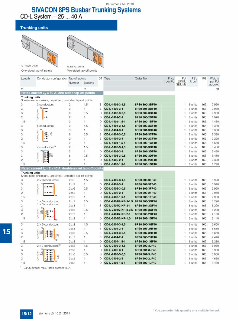
G_NSV0_01547 G_NSV0_01548
One-sided tap-off points Two-sided tap-off points
G_N
SV
0_01
549
L3
N
PE
G_N
SV
0_01
550
L3L2L1N
PE
L3N2
G_N
SV
0_01
551 L4
L3L2L1NL5
PE
L3N2
G_N
SV
0_01
552
L3
N
PE
PE
N
L3
G_N
SV
0_01
553
L3L2L1N
PE
PE
L3N2
N
L3
G_N
SV
0_01
554
L3L2L1N
PE
PE
L3N2
NL1L2L3
N2L3
G_N
SV
0_01
555 L4
L3L2L1NL5
PE
PE
L3N2
L5NL1L2L3
N2L3
L4
LV10-2_15_EN.book Seite 11 Mittwoch, 24. November 2010 11:06 11
© Siemens AG 2010
SIVACON 8PS Busbar Trunking SystemsCD-L System — 25 ... 40 A
Trunking units
15/12 Siemens LV 10.2 · 2011
15
* You can order this quantity or a multiple thereof.
1) L4/L5 circuit: max. rated current 25 A.
Length Conductor configuration Tap-off points DT Type Order No. Priceper PU
PU(UNIT,
SET, M)
PS*/P. unit
PG Weightper PU
approx.Number Spacing
m m kg
Rated current In = 40 A, one-sided tap-off pointsTrunking unitsSheet-steel enclosure, unpainted, uncoded tap-off points
3 3 conductors 2 1.5 B CD-L-1402-3-1,5 8PS0 300-3BF40 1 6 units 165 2.960
3 3 1 B CD-L-1402-3-1 8PS0 301-3BF40 1 6 units 165 2.960
3 6 0.5 D CD-L-1402-3-0,5 8PS0 302-3BF40 1 6 units 165 2.960
2 2 1 D CD-L-1402-2-1 8PS0 300-2BF40 1 6 units 165 1.970
1.5 2 1 D CD-L-1402-1,5-1 8PS0 300-1BF40 1 6 units 165 1.480
3 5 conductors 2 1.5 B CD-L-1404-3-1,5 8PS0 300-3CF40 1 6 units 165 3.330
3 3 1 B CD-L-1404-3-1 8PS0 301-3CF40 1 6 units 165 3.330
3 6 0.5 B CD-L-1404-3-0,5 8PS0 302-3CF40 1 6 units 165 3.330
2 2 1 B CD-L-1404-2-1 8PS0 300-2CF40 1 6 units 165 2.220
1.5 2 1 B CD-L-1404-1,5-1 8PS0 300-1CF40 1 6 units 165 1.660
3 7 conductors1) 2 1.5 B CD-L-1406-3-1,5 8PS0 300-3DF40 1 6 units 165 3.480
3 3 1 D CD-L-1406-3-1 8PS0 301-3DF40 1 6 units 165 3.480
3 6 0.5 D CD-L-1406-3-0,5 8PS0 302-3DF40 1 6 units 165 3.480
2 2 1 D CD-L-1406-2-1 8PS0 300-2DF40 1 6 units 165 2.320
1.5 2 1 D CD-L-1406-1,5-1 8PS0 300-1DF40 1 6 units 165 1.740
Rated current In = 2 × 40 A, double-sided tap-off pointsTrunking unitsSheet-steel enclosure, unpainted, uncoded tap-off points
3 2 × 3 conductors 2 x 2 1.5 B CD-L-2402-3-1,5 8PS0 300-3FF40 1 6 units 165 5.920
3 2 x 3 1 D CD-L-2402-3-1 8PS0 301-3FF40 1 6 units 165 5.920
3 2 x 6 0.5 D CD-L-2402-3-0,5 8PS0 302-3FF40 1 6 units 165 5.920
2 2 x 2 1 D CD-L-2402-2-1 8PS0 300-2FF40 1 6 units 165 3.940
1.5 2 x 2 1 D CD-L-2402-1,5-1 8PS0 300-1FF40 1 6 units 165 2.960
3 1 × 5 conductors1 × 3 conductors
2 x 2 1.5 B CD-L-2404/2-KR-3-1,5 8PS0 303-3GF40 1 6 units 165 6.290
3 2 x 3 1 B CD-L-2404/2-KR-3-1 8PS0 304-3GF40 1 6 units 165 6.290
3 2 x 6 0.5 B CD-L-2404/2-KR-3-0,5 8PS0 305-3GF40 1 6 units 165 6.290
2 2 x 2 1 B CD-L-2404/2-KR-2-1 8PS0 303-2GF40 1 6 units 165 4.190
1.5 2 x 2 1 D CD-L-2404/2-KR-1,5-1 8PS0 303-1GF40 1 6 units 165 3.140
3 2 × 5 conductors 2 x 2 1.5 B CD-L-2404-3-1,5 8PS0 300-3HF40 1 6 units 165 6.650
3 2 x 3 1 B CD-L-2404-3-1 8PS0 301-3HF40 1 6 units 165 6.650
3 2 x 6 0.5 B CD-L-2404-3-0,5 8PS0 302-3HF40 1 6 units 165 6.650
2 2 x 2 1 B CD-L-2404-2-1 8PS0 300-2HF40 1 6 units 165 4.440
1.5 2 x 2 1 D CD-L-2404-1,5-1 8PS0 300-1HF40 1 6 units 165 3.330
3 2 × 7 conductors1) 2 x 2 1.5 B CD-L-2406-3-1,5 8PS0 300-3JF40 1 6 units 165 6.950
3 2 x 3 1 D CD-L-2406-3-1 8PS0 301-3JF40 1 6 units 165 6.950
3 2 x 6 0.5 D CD-L-2406-3-0,5 8PS0 302-3JF40 1 6 units 165 6.950
2 2 x 2 1 D CD-L-2406-2-1 8PS0 300-2JF40 1 6 units 165 4.630
1.5 2 x 2 1 D CD-L-2406-1,5-1 8PS0 300-1JF40 1 6 units 165 3.470
One-sided tap-off points Two-sided tap-off points
G_NSV0_01547 G_NSV0_01548
G_N
SV
0_01
549
L3
N
PE
G_N
SV
0_01
550
L3L2L1N
PE
L3N2
G_N
SV
0_01
551 L4
L3L2L1NL5
PE
L3N2
G_N
SV
0_01
552
L3
N
PE
PE
N
L3
G_N
SV
0_01
553
L3L2L1N
PE
PE
L3N2
N
L3
G_N
SV
0_01
554
L3L2L1N
PE
PE
L3N2
NL1L2L3
N2L3
G_N
SV
0_01
555 L4
L3L2L1NL5
PE
PE
L3N2
L5NL1L2L3
N2L3
L4
LV10-2_15_EN.book Seite 12 Mittwoch, 24. November 2010 11:06 11
© Siemens AG 2010

15
SIVACON 8PS Busbar Trunking SystemsCD-L System — 25 ... 40 A
Trunking units
15/13Siemens LV 10.2 · 2011* You can order this quantity or a multiple thereof.
Unpainted trunking units with codable tap-off points (supplied from stock)
1) L4/L5 circuit: max. rated current 25 A.
Length Conductor configuration Tap-off points DT Type Order No. Priceper PU
PU(UNIT,
SET, M)
PS*/P. unit
PG Weightper PU
approx.Number Spacing
m m kg
Rated current In = 25 A, one-sided tap-off pointsTrunking units
Sheet-steel enclosure, unpainted, coded tap-off points
3 KR, 5 conductors
2 1.5 D CD-L-1254-KR-3-1,5 8PS0 310-3CF25 1 6 units 165 2.980
3 3 1 D CD-L-1254-KR-3-1 8PS0 311-3CF25 1 6 units 165 2.980
3 6 0.5 D CD-L-1254-KR-3-0,5 8PS0 312-3CF25 1 6 units 165 2.980
2 2 1 D CD-L-1254-KR-2-1 8PS0 310-2CF25 1 6 units 165 1.990
1.5 2 1 D CD-L-1254-KR-1,5-1 8PS0 310-1CF25 1 6 units 165 1.490
3 KW, 5 conductors
2 1.5 D CD-L-1254-KW-3-1,5 8PS0 313-3CF25 1 6 units 165 2.980
3 3 1 D CD-L-1254-KW-3-1 8PS0 314-3CF25 1 6 units 165 2.980
3 6 0.5 D CD-L-1254-KW-3-0,5 8PS0 315-3CF25 1 6 units 165 2.980
2 2 1 D CD-L-1254-KW-2-1 8PS0 313-2CF25 1 6 units 165 1.990
1.5 2 1 D CD-L-1254-KW-1.5-1 8PS0 313-1CF25 1 6 units 165 1.490
3 KR, 7 conductors1)
2 1.5 D CD-L-1256-KR-3-1,5 8PS0 310-3DF25 1 6 units 165 3.130
3 3 1 D CD-L-1256-KR-3-1 8PS0 311-3DF25 1 6 units 165 3.130
3 6 0.5 B CD-L-1256-KR-3-0,5 8PS0 312-3DF25 1 6 units 165 3.130
2 2 1 B CD-L-1256-KR-2-1 8PS0 310-2DF25 1 6 units 165 2.080
1.5 2 1 D CD-L-1256-KR-1.5-1 8PS0 310-1DF25 1 6 units 165 1.560
3 KW, 7 conductors1)
2 1.5 B CD-L-1256-KW-3-1,5 8PS0 313-3DF25 1 6 units 165 3.130
3 3 1 D CD-L-1256-KW-3-1 8PS0 314-3DF25 1 6 units 165 3.130
3 6 0.5 B CD-L-1256-KW-3-0,5 8PS0 315-3DF25 1 6 units 165 3.130
2 2 1 D CD-L-1256-KW-2-1 8PS0 313-2DF25 1 6 units 165 2.080
1.5 2 1 D CD-L-1256-KW-1,5-1 8PS0 313-1DF25 1 6 units 165 1.560
Rated current In = 2 × 25 A, double-sided tap-off pointsTrunking units
Sheet-steel enclosure, unpainted, coded tap-off points
3 KR, 1 × 5 conductors1 × 3 conductors
2 x 2 1.5 B CD-L-2254/2-KR-3-1,5 8PS0 303-3GF25 1 6 units 165 5.740
3 2 x 3 1 B CD-L-2254/2-KR-3-1 8PS0 304-3GF25 1 6 units 165 5.740
3 2 x 6 0.5 B CD-L-2254/2-KR-3-0,5 8PS0 305-3GF25 1 6 units 165 5.740
2 2 x 2 1 B CD-L-2254/2-KR-2-1 8PS0 303-2GF25 1 6 units 165 3.830
1.5 2 x 2 1 D CD-L-2254/2-KR-1,5-1 8PS0 303-1GF25 1 6 units 165 2.870
3 KR/KW, 2 × 5 conductors
2 x 2 1.5 D CD-L-2254-KRW-3-1,5 8PS0 316-3HF25 1 6 units 165 5.960
3 2 x 3 1 B CD-L-2254-KRW-3-1 8PS0 317-3HF25 1 6 units 165 5.960
3 2 x 6 0.5 D CD-L-2254-KRW-3-0,5 8PS0 318-3HF25 1 6 units 165 5.960
2 2 x 2 1 D CD-L-2254-KRW-2-1 8PS0 316-2HF25 1 6 units 165 3.970
1.5 2 x 2 1 B CD-L-2254-KRW-1,5-1 8PS0 316-1HF25 1 6 units 165 2.980
3 KR/KW, 2 × 7 conductors1)
2 x 2 1.5 D CD-L-2256-KRW-3-1,5 8PS0 316-3JF25 1 6 units 165 6.250
3 2 x 3 1 D CD-L-2256-KRW-3-1 8PS0 317-3JF25 1 6 units 165 6.250
3 2 x 6 0.5 D CD-L-2256-KRW-3-0,5 8PS0 318-3JF25 1 6 units 165 6.250
2 2 x 2 1 D CD-L-2256-KRW-2-1 8PS0 316-2JF25 1 6 units 165 4.170
1.5 2 x 2 1 D CD-L-2256-KRW-1,5-1 8PS0 316-1JF25 1 6 units 165 3.130
One-sided tap-off points, KR One-sided tap-off points, KW
G_NSV0_01558 G_NSV0_01564
Two-sided tap-off pointsG_NSV0_01559
G_N
SV
0_01
560
L3L2L1N
PEL3N2
G_N
SV
0_01
561
L3L2L1N
PEL3N2
G_N
SV
0_01
562 L4
L3L2L1NL5
PEL3N2
G_N
SV
0_01
563 L5
L3L2L1NL4
PEL3N2
G_N
SV
0_01
553
L3L2L1N
PE
PE
L3N2
N
L3
G_N
SV
0_01
565
L3L2L1N
PE
PE
L3N2
NL1L2L3
N2L3
L4L3L2L1NL5
PE
PE
L3N2
L5NL1L2L3
N2L3
L4G_N
SV
0_01
566
LV10-2_15_EN.book Seite 13 Mittwoch, 24. November 2010 11:06 11
© Siemens AG 2010

SIVACON 8PS Busbar Trunking SystemsCD-L System — 25 ... 40 A
Trunking units
15/14 Siemens LV 10.2 · 2011
15
* You can order this quantity or a multiple thereof.
1) L4/L5 circuit: max. rated current 25 A.
Length Conductor configuration Tap-off points DT Type Order No. Priceper PU
PU(UNIT,
SET, M)
PS*/P. unit
PG Weightper PU
approx.Number Spacing
m m kg
Rated current In = 40 A, one-sided tap-off pointsTrunking unitsSheet-steel enclosure, unpainted, coded tap-off points
3 KR, 5 conductors
2 1.5 D CD-L-1404-KR-3-1,5 8PS0 310-3CF40 1 6 units 165 3.330
3 3 1 D CD-L-1404-KR-3-1 8PS0 311-3CF40 1 6 units 165 3.330
3 6 0.5 D CD-L-1404-KR-3-0,5 8PS0 312-3CF40 1 6 units 165 3.330
2 2 1 D CD-L-1404-KR-2-1 8PS0 310-2CF40 1 6 units 165 2.220
1.5 2 1 D CD-L-1404-KR-1,5-1 8PS0 310-1CF40 1 6 units 165 1.660
3 KW, 5 conductors
2 1.5 D CD-L-1404-KW-3-1,5 8PS0 313-3CF40 1 6 units 165 3.330
3 3 1 D CD-L-1404-KW-3-1 8PS0 314-3CF40 1 6 units 165 3.330
3 6 0.5 D CD-L-1404-KW-3-0,5 8PS0 315-3CF40 1 6 units 165 3.330
2 2 1 D CD-L-1404-KW-2-1 8PS0 313-2CF40 1 6 units 165 2.220
1.5 2 1 D CD-L-1404-KW-1,5-1 8PS0 313-1CF40 1 6 units 165 1.660
3 KR, 7 conductors1)
2 1.5 D CD-L-1406-KR-3-1,5 8PS0 310-3DF40 1 6 units 165 3.480
3 3 1 D CD-L-1406-KR-3-1 8PS0 311-3DF40 1 6 units 165 3.480
3 6 0.5 D CD-L-1406-KR-3-0,5 8PS0 312-3DF40 1 6 units 165 3.480
2 2 1 B CD-L-1406-KR-2-1 8PS0 310-2DF40 1 6 units 165 2.320
1.5 2 1 D CD-L-1406-KR-1,5-1 8PS0 310-1DF40 1 6 units 165 1.740
3 KW, 7 conductors1)
2 1.5 D CD-L-1406-KW-3-1,5 8PS0 313-3DF40 1 6 units 165 3.480
3 3 1 D CD-L-1406-KW-3-1 8PS0 314-3DF40 1 6 units 165 3.480
3 6 0.5 D CD-L-1406-KW-3-0,5 8PS0 315-3DF40 1 6 units 165 3.480
2 2 1 D CD-L-1406-KW-2-1 8PS0 313-2DF40 1 6 units 165 2.320
1.5 2 1 D CD-L-1406-KW-1,5-1 8PS0 313-1DF40 1 6 units 165 1.740
Rated current In = 2 × 40 A, double-sided tap-off pointsTrunking unitsSheet-steel enclosure, unpainted, coded tap-off points
3 KR, 1 × 5 conductors1 × 3 conductors
2 x 2 1.5 B CD-L-2404/2-KR-3-1,5 8PS0 303-3GF40 1 6 units 165 6.290
3 2 x 3 1 B CD-L-2404/2-KR-3-1 8PS0 304-3GF40 1 6 units 165 6.290
3 2 x 6 0.5 B CD-L-2404/2-KR-3-0,5 8PS0 305-3GF40 1 6 units 165 6.290
2 2 x 2 1 B CD-L-2404/2-KR-2-1 8PS0 303-2GF40 1 6 units 165 4.190
1.5 2 x 2 1 D CD-L-2404/2-KR-1,5-1 8PS0 303-1GF40 1 6 units 165 3.140
3 KR/KW, 2 × 5 conductors
2 x 2 1.5 D CD-L-2404-KRW-3-1.5 8PS0 316-3HF40 1 6 units 165 6.650
3 2 x 3 1 D CD-L-2404-KRW-3-1 8PS0 317-3HF40 1 6 units 165 6.650
3 2 x 6 0.5 D CD-L-2404-KRW-3-0,5 8PS0 318-3HF40 1 6 units 165 6.650
2 2 x 2 1 X CD-L-2404-KRW-2-1 8PS0 316-2HF40 1 6 units 165 4.440
1.5 2 x 2 1 D CD-L-2404-KRW-1,5-1 8PS0 316-1HF40 1 6 units 165 3.330
3 KR/KW, 2 × 7 conductors1)
2 x 2 1.5 D CD-L-2406-KRW-3-1,5 8PS0 316-3JF40 1 6 units 165 6.950
3 2 x 3 1 D CD-L-2406-KRW-3-1 8PS0 317-3JF40 1 6 units 165 6.950
3 2 x 6 0.5 D CD-L-2406-KRW-3-0,5 8PS0 318-3JF40 1 6 units 165 6.950
2 2 x 2 1 D CD-L-2406-KRW-2-1 8PS0 316-2JF40 1 6 units 165 4.630
1.5 2 x 2 1 D CD-L-2406-KRW-1,5-1 8PS0 316-1JF40 1 6 units 165 3.470
One-sided tap-off points, KR One-sided tap-off points, KW Two-sided tap-off points
G_NSV0_01558 G_NSV0_01564 G_NSV0_01559
G_N
SV
0_01
560
L3L2L1N
PEL3N2
G_N
SV
0_01
561
L3L2L1N
PEL3N2
G_N
SV
0_01
562 L4
L3L2L1NL5
PEL3N2
G_N
SV
0_01
563 L5
L3L2L1NL4
PEL3N2
G_N
SV
0_01
553
L3L2L1N
PE
PE
L3N2
N
L3
G_N
SV
0_01
565
L3L2L1N
PE
PE
L3N2
NL1L2L3
N2L3
L4L3L2L1NL5
PE
PE
L3N2
L5NL1L2L3
N2L3
L4G_N
SV
0_01
566
LV10-2_15_EN.book Seite 14 Mittwoch, 24. November 2010 11:06 11
© Siemens AG 2010

15
SIVACON 8PS Busbar Trunking SystemsCD-L System — 25 ... 40 A
Trunking units
15/15Siemens LV 10.2 · 2011* You can order this quantity or a multiple thereof.
Painted trunking units with uncoded tap-off points (delivery on request)
1) L4/L5 circuit: max. rated current 25 A.
Length Conductor configuration
Tap-off points DT Type Order No. Priceper PU
PU(UNIT,
SET, M)
PS*/P. unit
PG Weightper PU
approx.Number Spacing
m m kg
Rated current In = 25 A, one-sided tap-off pointsTrunking unitsSheet-steel enclosure, painted, white (RAL 9016), uncoded tap-off points
3 3 conductors 2 1.5 X CD-L-1252-3-1,5-L 8PS1 300-3BF25 1 6 units 165 2.770
3 3 1 X CD-L-1252-3-1-L 8PS1 301-3BF25 1 6 units 165 2.770
3 6 0.5 X CD-L-1252-3-0,5-L 8PS1 302-3BF25 1 6 units 165 2.770
2 2 1 X CD-L-1252-2-1-L 8PS1 300-2BF25 1 6 units 165 1.840
1.5 2 1 X CD-L-1252-1,5-1-L 8PS1 300-1BF25 1 6 units 165 1.380
3 5 conductors 2 1.5 X CD-L-1254-3-1,5-L 8PS1 300-3CF25 1 6 units 165 2.980
3 3 1 X CD-L-1254-3-1-L 8PS1 301-3CF25 1 6 units 165 2.980
3 6 0.5 X CD-L-1254-3-0,5-L 8PS1 302-3CF25 1 6 units 165 2.980
2 2 1 X CD-L-1254-2-1-L 8PS1 300-2CF25 1 6 units 165 1.990
1.5 2 1 X CD-L-1254-1,5-1-L 8PS1 300-1CF25 1 6 units 165 1.490
3 7 conductors1) 2 1.5 X CD-L-1256-3-1,5-L 8PS1 300-3DF25 1 6 units 165 3.480
3 3 1 X CD-L-1256-3-1-L 8PS1 301-3DF25 1 6 units 165 3.480
3 6 0.5 X CD-L-1256-3-0,5-L 8PS1 302-3DF25 1 6 units 165 3.480
2 2 1 X CD-L-1256-2-1-L 8PS1 300-2DF25 1 6 units 165 2.320
1.5 2 1 X CD-L-1256-1,5-1-L 8PS1 300-1DF25 1 6 units 165 1.740Rated current In = 2 × 25 A, double-sided tap-off pointsTrunking unitsSheet-steel enclosure, painted, white (RAL 9016), uncoded tap-off points
3 2 × 3 conductors 2 x 2 1.5 X CD-L-2252-3-1,5-L 8PS1 300-3FF25 1 6 units 165 5.530
3 2 x 3 1 X CD-L-2252-3-1-L 8PS1 301-3FF25 1 6 units 165 5.530
3 2 x 6 0.5 X CD-L-2252-3-0,5-L 8PS1 302-3FF25 1 6 units 165 5.530
2 2 x 2 1 X CD-L-2252-2-1-L 8PS1 300-2FF25 1 6 units 165 3.690
1.5 2 x 2 1 X CD-L-2252-1,5-1-L 8PS1 300-1FF25 1 6 units 165 2.770
3 1 × 5 conductors1 × 3 conductors
2 x 2 1.5 X CD-L-2254/2-KR-3-1,5-L 8PS1 303-3GF25 1 6 units 165 5.740
3 2 x 3 1 X CD-L-2254/2-KR-3-1-L 8PS1 304-3GF25 1 6 units 165 5.740
3 2 x 6 0.5 X CD-L-2254/2-KR-3-0.5-L 8PS1 305-3GF25 1 6 units 165 5.740
2 2 x 2 1 X CD-L-2254/2-KR-2-1-L 8PS1 303-2GF25 1 6 units 165 3.830
1.5 2 x 2 1 X CD-L-2254/2-KR-1,5-1-L 8PS1 303-1GF25 1 6 units 165 2.870
3 2 × 5 conductors 2 x 2 1.5 X CD-L-2254-3-1,5-L 8PS1 300-3HF25 1 6 units 165 5.960
3 2 x 3 1 X CD-L-2254-3-1-L 8PS1 301-3HF25 1 6 units 165 5.960
3 2 x 6 0.5 X CD-L-2254-3-0,5-L 8PS1 302-3HF25 1 6 units 165 5.960
2 2 x 2 1 X CD-L-2254-2-1-L 8PS1 300-2HF25 1 6 units 165 3.970
1.5 2 x 2 1 X CD-L-2254-1,5-1-L 8PS1 300-1HF25 1 6 units 165 2.980
3 2 × 7 conductors1) 2 x 2 1.5 X CD-L-2256-3-1,5-L 8PS1 300-3JF25 1 6 units 165 6.250
3 2 x 3 1 X CD-L-2256-3-1-L 8PS1 301-3JF25 1 6 units 165 6.250
3 2 x 6 0.5 X CD-L-2256-3-0,5-L 8PS1 302-3JF25 1 6 units 165 6.250
2 2 x 2 1 X CD-L-2256-2-1-L 8PS1 300-2JF25 1 6 units 165 4.170
1.5 2 x 2 1 X CD-L-2256-1,5-1-L 8PS1 300-1JF25 1 6 units 165 3.130
One-sided tap-off points Two-sided tap-off points
G_NSV0_01556 G_NSV0_01557
G_N
SV
0_01
549
L3
N
PE
G_N
SV
0_01
550
L3L2L1N
PE
L3N2
G_N
SV
0_01
551 L4
L3L2L1NL5
PE
L3N2
G_N
SV
0_01
552
L3
N
PE
PE
N
L3
G_N
SV
0_01
553
L3L2L1N
PE
PE
L3N2
N
L3
G_N
SV
0_01
554
L3L2L1N
PE
PE
L3N2
NL1L2L3
N2L3
G_N
SV
0_01
555 L4
L3L2L1NL5
PE
PE
L3N2
L5NL1L2L3
N2L3
L4
LV10-2_15_EN.book Seite 15 Mittwoch, 24. November 2010 11:06 11
© Siemens AG 2010

SIVACON 8PS Busbar Trunking SystemsCD-L System — 25 ... 40 A
Trunking units
15/16 Siemens LV 10.2 · 2011
15
* You can order this quantity or a multiple thereof.
1) L4/L5 circuit: max. rated current 25 A.
Length Conductor configuration
Tap-off points DT Type Order No. Priceper PU
PU(UNIT,
SET, M)
PS*/P. unit
PG Weightper PU
approx.Number Spacing
m m kg
Rated current In = 40 A, one-sided tap-off pointsTrunking unitsSheet-steel enclosure, painted, white (RAL 9016), uncoded tap-off points
3 3 conductors 2 1.5 X CD-L-1402-3-1,5-L 8PS1 300-3BF40 1 6 units 165 2.960
3 3 1 X CD-L-1402-3-1-L 8PS1 301-3BF40 1 6 units 165 2.960
3 6 0.5 X CD-L-1402-3-0,5-L 8PS1 302-3BF40 1 6 units 165 2.960
2 2 1 X CD-L-1402-2-1-L 8PS1 300-2BF40 1 6 units 165 1.970
1.5 2 1 X CD-L-1402-1,5-1-L 8PS1 300-1BF40 1 6 units 165 1.480
3 5 conductors 2 1.5 X CD-L-1404-3-1,5-L 8PS1 300-3CF40 1 6 units 165 3.330
3 3 1 X CD-L-1404-3-1-L 8PS1 301-3CF40 1 6 units 165 3.330
3 6 0.5 X CD-L-1404-3-0,5-L 8PS1 302-3CF40 1 6 units 165 3.330
2 2 1 X CD-L-1404-2-1-L 8PS1 300-2CF40 1 6 units 165 2.220
1.5 2 1 X CD-L-1404-1,5-1-L 8PS1 300-1CF40 1 6 units 165 1.660
3 7 conductors1) 2 1.5 X CD-L-1406-3-1,5-L 8PS1 300-3DF40 1 6 units 165 3.480
3 3 1 X CD-L-1406-3-1-L 8PS1 301-3DF40 1 6 units 165 3.480
3 6 0.5 X CD-L-1406-3-0,5-L 8PS1 302-3DF40 1 6 units 165 3.480
2 2 1 X CD-L-1406-2-1-L 8PS1 300-2DF40 1 6 units 165 2.320
1.5 2 1 X CD-L-1406-1,5-1-L 8PS1 300-1DF40 1 6 units 165 1.740Rated current In = 2 × 40 A, double-sided tap-off pointsTrunking unitsSheet-steel enclosure, painted, white (RAL 9016), uncoded tap-off points
3 2 × 3 conductors 2 x 2 1.5 X CD-L-2402-3-1,5-L 8PS1 300-3FF40 1 6 units 165 5.920
3 2 x 3 1 X CD-L-2402-3-1-L 8PS1 301-3FF40 1 6 units 165 5.920
3 2 x 6 0.5 X CD-L-2402-3-0,5-L 8PS1 302-3FF40 1 6 units 165 5.920
2 2 x 2 1 X CD-L-2402-2-1-L 8PS1 300-2FF40 1 6 units 165 3.940
1.5 2 x 2 1 X CD-L-2402-1,5-1-L 8PS1 300-1FF40 1 6 units 165 2.960
3 1 × 5 conductors1 × 3 conductors
2 x 2 1.5 X CD-L-2404/2-KR-3-1,5-L 8PS1 303-3GF40 1 6 units 165 6.290
3 2 x 3 1 X CD-L-2404/2-KR-3-1-L 8PS1 304-3GF40 1 6 units 165 6.290
3 2 x 6 0.5 X CD-L-2404/2-KR-3-0,5-L 8PS1 305-3GF40 1 6 units 165 6.290
2 2 x 2 1 X CD-L-2404/2-KR-2-1-L 8PS1 303-2GF40 1 6 units 165 4.190
1.5 2 x 2 1 X CD-L-2404/2-KR-1,5-1-L 8PS1 303-1GF40 1 6 units 165 3.140
3 2 × 5 conductors 2 x 2 1.5 X CD-L-2404-3-1,5-L 8PS1 300-3HF40 1 6 units 165 6.650
3 2 x 3 1 X CD-L-2404-3-1-L 8PS1 301-3HF40 1 6 units 165 6.650
3 2 x 6 0.5 X CD-L-2404-3-0,5-L 8PS1 302-3HF40 1 6 units 165 6.650
2 2 x 2 1 X CD-L-2404-2-1-L 8PS1 300-2HF40 1 6 units 165 4.440
1.5 2 x 2 1 X CD-L-2404-1,5-1-L 8PS1 300-1HF40 1 6 units 165 3.330
3 2 × 7 conductors1) 2 x 2 1.5 X CD-L-2406-3-1,5-L 8PS1 300-3JF40 1 6 units 165 6.950
3 2 x 3 1 X CD-L-2406-3-1-L 8PS1 301-3JF40 1 6 units 165 6.950
3 2 x 6 0.5 X CD-L-2406-3-0,5-L 8PS1 302-3JF40 1 6 units 165 6.950
2 2 x 2 1 X CD-L-2406-2-1-L 8PS1 300-2JF40 1 6 units 165 4.630
1.5 2 x 2 1 X CD-L-2406-1,5-1-L 8PS1 300-1JF40 1 6 units 165 3.470
One-sided tap-off points Two-sided tap-off points
G_NSV0_01556 G_NSV0_01557
G_N
SV
0_01
549
L3
N
PE
G_N
SV
0_01
550
L3L2L1N
PE
L3N2
G_N
SV
0_01
551 L4
L3L2L1NL5
PE
L3N2
G_N
SV
0_01
552
L3
N
PE
PE
N
L3
G_N
SV
0_01
553
L3L2L1N
PE
PE
L3N2
N
L3
G_N
SV
0_01
554
L3L2L1N
PE
PE
L3N2
NL1L2L3
N2L3
G_N
SV
0_01
555 L4
L3L2L1NL5
PE
PE
L3N2
L5NL1L2L3
N2L3
L4
LV10-2_15_EN.book Seite 16 Mittwoch, 24. November 2010 11:06 11
© Siemens AG 2010

15
SIVACON 8PS Busbar Trunking SystemsCD-L System — 25 ... 40 A
Feeder units
15/17Siemens LV 10.2 · 2011* You can order this quantity or a multiple thereof.
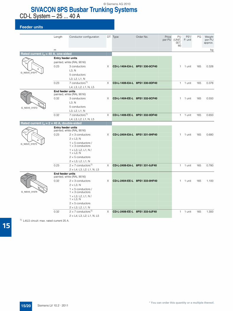
■ Overview
The feeder units are inserted at the beginning of a busbar line. They are available as entry feeder units and end feeder units and are connected to the corresponding end of the straight ele-ment (the entry feeder unit without a connecting flange, the end feeder unit with a connecting flange).
If there are busbar elements on two sides, the two circuits are mechanically separated.
Enclosure material
Connection box: ThermoplastConnection point: Galvanized metal enclosure
Conductor cross-sections of the terminals
N/L1/L2/L3: Max. cable cross-section 10 mm2
L4/L5: Max. cable cross-section 2.5 mm2
PU: Max. cable cross-section 6 mm2
■ Selection and ordering data
Unpainted feeder units (supplied from stock)
1) L4/L5 circuit: max. rated current 25 A.
Length Conductor configuration DT Type Order No. Priceper PU
PU(UNIT,
SET,M)
PS*/P. unit
PG Weightper PU
approx.
m kg
Rated current In = 25 A, one-sidedEntry feeder unitsunpainted (coded KR, KW)
0.23 3 conductors B CD-L-1254-EA 8PS0 330-0CF25 1 1 unit 165 0.325
L3, N
5 conductors
L3, L2, L1, N
0.23 7 conductors1) B CD-L-1256-EA 8PS0 330-0DF25 1 1 unit 165 0.375
L4, L3, L2, L1, N, L5
End feeder unitsunpainted (coded KR, KW)
0.32 3 conductors B CD-L-1254-EE 8PS0 332-0CF25 1 1 unit 165 0.520
L3, N
5 conductors
L3, L2, L1, N
0.32 7 conductors1) B CD-L-1256-EE 8PS0 332-0DF25 1 1 unit 165 0.620
L4, L3, L2, L1, N, L5
Rated current In = 2 × 25 A, double-sidedEntry feeder unitsunpainted (coded KR, KW)
0.23 2 × 3 conductors B CD-L-2254-EA 8PS0 331-0HF25 1 1 unit 165 0.650
2 × L3, N
1 × 5 conductors / 1 × 3 conductors
1 × L3, L2, L1, N / 1 × L3, N
2 × 5 conductors
2 × L3, L2, L1, N
0.23 2 × 7 conductors1) B CD-L-2256-EA 8PS0 331-0JF25 1 1 unit 165 0.750
2 × L4, L3, L2, L1, N, L5
End feeder unitsunpainted (coded KR, KW)
0.32 2 × 3 conductors B CD-L-2254-EE 8PS0 333-0HF25 1 1 unit 165 1.040
2 × L3, N
1 × 5 conductors / 1 × 3 conductors
1 × L3, L2, L1, N / 1 × L3, N
2 × 5 conductors
2 × L3, L2, L1, N
0.32 2 × 7 conductors1) B CD-L-2256-EE 8PS0 333-0JF25 1 1 unit 165 1.240
2 × L4, L3, L2, L1, N, L5
G_NSV0_01567
G_NSV0_01569
G_NSV0_01568
G_NSV0_01570
LV10-2_15_EN.book Seite 17 Mittwoch, 24. November 2010 11:06 11
© Siemens AG 2010

SIVACON 8PS Busbar Trunking SystemsCD-L System — 25 ... 40 A
Feeder units
15/18 Siemens LV 10.2 · 2011
15
* You can order this quantity or a multiple thereof.
1) L4/L5 circuit: max. rated current 25 A.
Length Conductor configuration DT Type Order No. Priceper PU
PU(UNIT,
SET,M)
PS*/P. unit
PG Weightper PU
approx.
m kg
Rated current In = 40 A, one-sidedEntry feeder unitsunpainted (coded KR, KW)
0.23 3 conductors B CD-L-1404-EA 8PS0 330-0CF40 1 1 unit 165 0.328
L3, N
5 conductors
L3, L2, L1, N
0.23 7 conductors1) B CD-L-1406-EA 8PS0 330-0DF40 1 1 unit 165 0.378
L4, L3, L2, L1, N, L5
End feeder unitsunpainted (coded KR, KW)
0.32 3 conductors B CD-L-1404-EE 8PS0 332-0CF40 1 1 unit 165 0.550
L3, N
5 conductors
L3, L2, L1, N
0.32 7 conductors1) B CD-L-1406-EE 8PS0 332-0DF40 1 1 unit 165 0.650
L4, L3, L2, L1, N, L5
Rated current In = 2 × 40 A, double-sidedEntry feeder unitsunpainted (coded KR, KW)
0.23 2 × 3 conductors B CD-L-2404-EA 8PS0 331-0HF40 1 1 unit 165 0.680
2 × L3, N
1 × 5 conductors / 1 × 3 conductors
1 × L3, L2, L1, N / 1 × L3, N
2 × 5 conductors
2 × L3, L2, L1, N
0.23 2 × 7 conductors1) B CD-L-2406-EA 8PS0 331-0JF40 1 1 unit 165 0.780
2 × L4, L3, L2, L1, N, L5
End feeder unitsunpainted (coded KR, KW)
0.32 2 × 3 conductors B CD-L-2404-EE 8PS0 333-0HF40 1 1 unit 165 1.100
2 × L3, N
1 × 5 conductors / 1 × 3 conductors
1 × L3, L2, L1, N / 1 × L3, N
2 × 5 conductors
2 × L3, L2, L1, N
0.32 2 × 7 conductors1) D CD-L-2406-EE 8PS0 333-0JF40 1 1 unit 165 1.300
2 × L4, L3, L2, L1, N, L5
G_NSV0_01567
G_NSV0_01569
G_NSV0_01568
G_NSV0_01570
LV10-2_15_EN.book Seite 18 Mittwoch, 24. November 2010 11:06 11
© Siemens AG 2010

15
SIVACON 8PS Busbar Trunking SystemsCD-L System — 25 ... 40 A
Feeder units
15/19Siemens LV 10.2 · 2011* You can order this quantity or a multiple thereof.
Painted feeder units (delivery on request)
1) L4/L5 circuit: max. rated current 25 A.
Length Conductor configuration DT Type Order No. Priceper PU
PU(UNIT,
SET,M)
PS*/P. unit
PG Weightper PU
approx.
m kg
Rated current In = 25 A, one-sidedEntry feeder unitspainted, white (RAL 9016)
0.23 3 conductors X CD-L-1254-EA-L 8PS1 330-0CF25 1 1 unit 165 0.325
L3, N
5 conductors
L3, L2, L1, N
0.23 7 conductors1) X CD-L-1256-EA-L 8PS1 330-0DF25 1 1 unit 165 0.375
L4, L3, L2, L1, N, L5
End feeder unitspainted, white (RAL 9016)
0.32 3 conductors X CD-L-1254-EE-L 8PS1 332-0CF25 1 1 unit 165 0.520
L3, N
5 conductors
L3, L2, L1, N
0.32 7 conductors1) X CD-L-1256-EE-L 8PS1 332-0DF25 1 1 unit 165 0.620
L4, L3, L2, L1, N, L5
Rated current In = 2 × 25 A, double-sidedEntry feeder unitspainted, white (RAL 9016)
0.23 2 × 3 conductors X CD-L-2254-EA-L 8PS1 331-0HF25 1 1 unit 165 0.650
2 × L3, N
1 × 5 conductors / 1 × 3 conductors
1 × L3, L2, L1, N / 1 × L3, N
2 × 5 conductors
2 × L3, L2, L1, N
0.23 2 × 7 conductors1) X CD-L-2256-EA-L 8PS1 331-0JF25 1 1 unit 165 0.750
2 × L4, L3, L2, L1, N, L5
End feeder unitspainted, white (RAL 9016)
0.32 2 × 3 conductors X CD-L-2254-EE-L 8PS1 333-0HF25 1 1 unit 165 1.040
2 × L3, N
1 × 5 conductors / 1 × 3 conductors
1 × L3, L2, L1, N / 1 × L3, N
2 × 5 conductors
2 × L3, L2, L1, N
0.32 2 × 7 conductors1) X CD-L-2256-EE-L 8PS1 333-0JF25 1 1 unit 165 1.240
2 × L4, L3, L2, L1, N, L5
G_NSV0_01571
G_NSV0_01572
G_NSV0_01573
G_NSV0_01574
LV10-2_15_EN.book Seite 19 Mittwoch, 24. November 2010 11:06 11
© Siemens AG 2010
SIVACON 8PS Busbar Trunking SystemsCD-L System — 25 ... 40 A
Feeder units
15/20 Siemens LV 10.2 · 2011
15
* You can order this quantity or a multiple thereof.
1) L4/L5 circuit: max. rated current 25 A.
Length Conductor configuration DT Type Order No. Priceper PU
PU(UNIT,
SET,M)
PS*/P. unit
PG Weightper PU
approx.
m kg
Rated current In = 40 A, one-sidedEntry feeder units
painted, white (RAL 9016)
0.23 3 conductors X CD-L-1404-EA-L 8PS1 330-0CF40 1 1 unit 165 0.328
L3, N
5 conductors
L3, L2, L1, N
0.23 7 conductors1) X CD-L-1406-EA-L 8PS1 330-0DF40 1 1 unit 165 0.378
L4, L3, L2, L1, N, L5
End feeder unitspainted, white (RAL 9016)
0.32 3 conductors X CD-L-1404-EE-L 8PS1 332-0CF40 1 1 unit 165 0.550
L3, N
5 conductors
L3, L2, L1, N
0.32 7 conductors1) X CD-L-1406-EE-L 8PS1 332-0DF40 1 1 unit 165 0.650
L4, L3, L2, L1, N, L5
Rated current In = 2 × 40 A, double-sidedEntry feeder unitspainted, white (RAL 9016)
0.23 2 × 3 conductors X CD-L-2404-EA-L 8PS1 331-0HF40 1 1 unit 165 0.680
2 × L3, N
1 × 5 conductors / 1 × 3 conductors
1 × L3, L2, L1, N / 1 × L3, N
2 × 5 conductors
2 × L3, L2, L1, N
0.23 2 × 7 conductors1) X CD-L-2406-EA-L 8PS1 331-0JF40 1 1 unit 165 0.780
2 × L4, L3, L2, L1, N, L5
End feeder unitspainted, white (RAL 9016)
0.32 2 × 3 conductors X CD-L-2404-EE-L 8PS1 333-0HF40 1 1 unit 165 1.100
2 × L3, N
1 × 5 conductors / 1 × 3 conductors
1 × L3, L2, L1, N / 1 × L3, N
2 × 5 conductors
2 × L3, L2, L1, N
0.32 2 × 7 conductors1) X CD-L-2406-EE-L 8PS1 333-0JF40 1 1 unit 165 1.300
2 × L4, L3, L2, L1, N, L5
G_NSV0_01571
G_NSV0_01572
G_NSV0_01573
G_NSV0_01574
LV10-2_15_EN.book Seite 20 Mittwoch, 24. November 2010 11:06 11
© Siemens AG 2010

15
SIVACON 8PS Busbar Trunking SystemsCD-L System — 25 ... 40 A
End flanges
15/21Siemens LV 10.2 · 2011* You can order this quantity or a multiple thereof.
■ Overview
The end flanges serve as touch protection at the end of the bus-bar line. They are available in two versions (end cap as mating piece for the entry feeder unit and end cap with connecting piece as mating piece for the end feeder unit). They are con-nected to the corresponding end of the straight element.
Enclosure material
End cover: ThermoplastConnecting piece (only EE-EF): Galvanized metal enclosure
■ Selection and ordering data
Unpainted end flanges (supplied from stock)
Length Conductor configuration DT Type Order No. Priceper PU
PU(UNIT,
SET,M)
PS*/P. unit
PG Weightper PU
approx.
m kg
Rated current In = 25 and 40 A, one-sidedEnd flanges(coded KR, KW), can be used with entry feeder unit
0.052 3 conductors B CD-L-1406-EA-EF 8PS1 337-0DF40 1 1 unit 165 0.030
L3, N
5 conductors
L3, L2, L1, N
7 conductors
L4, L3, L2, L1, N, L5
End flangesunpainted (coded KR, KW), can be used with end feeder unit
0.155 3 conductors B CD-L-1406-EE-EF 8PS0 335-0DF40 1 1 unit 165 0.200
L3, N
5 conductors
L3, L2, L1, N
7 conductors
L4, L3, L2, L1, N, L5
Rated current In = 2 × 25 and 2 × 40 A, double-sidedEnd flanges(coded KR, KW), can be used with entry feeder unit
0.052 2 × 3 conductors B CD-L-2406-EA-EF 8PS1 338-0JF40 1 1 unit 165 0.040
2 × L3, N
1 × 5 conductors / 1 × 3 conductors
1 × L3, L2, L1, N / 1 × L3, N
2 × 5 conductors
2 × L3, L2, L1, N
2 × 7 conductors
2 × L4, L3, L2, L1, N, L5
End flangesunpainted (coded KR, KW), can be used with end feeder unit
0.155 2 × 3 conductors B CD-L-2406-EE-EF 8PS0 336-0JF40 1 1 unit 165 0.370
2 × L3, N
1 × 5 conductors / 1 × 3 conductors
1 × L3, L2, L1, N / 1 × L3, N
2 × 5 conductors
2 × L3, L2, L1, N
2 × 7 conductors
2 × L4, L3, L2, L1, N, L5
G_NSV0_01576
G_NSV0_01575
G_NSV0_01578
G_NSV0_01577
LV10-2_15_EN.book Seite 21 Mittwoch, 24. November 2010 11:06 11
© Siemens AG 2010

SIVACON 8PS Busbar Trunking SystemsCD-L System — 25 ... 40 A
End flanges
15/22 Siemens LV 10.2 · 2011
15
* You can order this quantity or a multiple thereof.
Painted end flanges (delivery on request)
Length Conductor configuration DT Type Order No. Priceper PU
PU(UNIT,
SET,M)
PS*/P. unit
PG Weightper PU
approx.
m kg
Rated current In = 25 and 40 A, one-sidedEnd flangescan be used with entry feeder unit
0.052 3 conductors B CD-L-1406-EA-EF 8PS1 337-0DF40 1 1 unit 165 0.030
L3, N
5 conductors
L3, L2, L1, N
7 conductors
L4, L3, L2, L1, N, L5
End flangespainted, white (RAL 9016) can be used with end feeder unit
0.155 3 conductors X CD-L-1406-EE-EF-L 8PS1 335-0DF40 1 1 unit 165 0.200
L3, N
5 conductors
L3, L2, L1, N
7 conductors
L4, L3, L2, L1, N, L5
Rated current In = 2 × 25 and 2 × 40 A, double-sidedEnd flangescan be used with entry feeder unit
0.052 2 × 3 conductors B CD-L-2406-EA-EF 8PS1 338-0JF40 1 1 unit 165 0.040
2 × L3, N
1 × 5 conductors / 1 × 3 conductors
1 × L3, L2, L1, N / 1 × L3, N
2 × 5 conductors
2 × L3, L2, L1, N
2 × 7 conductors
2 × L4, L3, L2, L1, N, L5
End flangespainted, white (RAL 9016) can be used with end feeder unit
0.155 2 × 3 conductors X CD-L-2406-EE-EF-L 8PS1 336-0JF40 1 1 unit 165 0.370
2 × L3, N
1 × 5 conductors / 1 × 3 conductors
1 × L3, L2, L1, N / 1 × L3, N
2 × 5 conductors
2 × L3, L2, L1, N
2 × 7 conductors
2 × L4, L3, L2, L1, N, L5
G_NSV0_01576
G_NSV0_01579
G_NSV0_01578
G_NSV0_01580
LV10-2_15_EN.book Seite 22 Mittwoch, 24. November 2010 11:06 11
© Siemens AG 2010
15
SIVACON 8PS Busbar Trunking SystemsCD-L System — 25 ... 40 A
Junction units
15/23Siemens LV 10.2 · 2011* You can order this quantity or a multiple thereof.
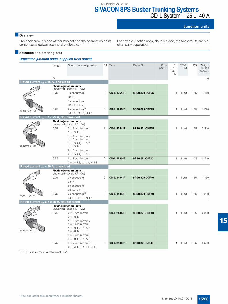
■ Overview
The enclosure is made of thermoplast and the connection point comprises a galvanized metal enclosure.
For flexible junction units, double-sided, the two circuits are me-chanically separated.
■ Selection and ordering data
Unpainted junction units (supplied from stock)
1) L4/L5 circuit: max. rated current 25 A.
Length Conductor configuration DT Type Order No. Priceper PU
PU(UNIT,
SET,M)
PS*/P.unit
PG Weightper PU
approx.
m kg
Rated current In = 25 A, one-sidedFlexible junction unitsunpainted (coded KR, KW)
0.75 3 conductors D CD-L-1254-R 8PS0 320-0CF25 1 1 unit 165 1.170
L3, N
5 conductors
L3, L2, L1, N
0.75 7 conductors1) B CD-L-1256-R 8PS0 320-0DF25 1 1 unit 165 1.270
L4, L3, L2, L1, N, L5
Rated current In = 2 × 25 A, double-sidedFlexible junction unitsunpainted (coded KR, KW)
0.75 2 × 3 conductors B CD-L-2254-R 8PS0 321-0HF25 1 1 unit 165 2.340
2 × L3, N
1 × 5 conductors / 1 × 3 conductors
1 × L3, L2, L1, N / 1 × L3, N
2 × 5 conductors
2 × L3, L2, L1, N
0.75 2 × 7 conductors1) B CD-L-2256-R 8PS0 321-0JF25 1 1 unit 165 2.540
2 × L4, L3, L2, L1, N, L5
Rated current In = 40 A, one-sidedFlexible junction unitsunpainted (coded KR, KW)
0.75 3 conductors D CD-L-1404-R 8PS0 320-0CF40 1 1 unit 165 1.180
L3, N
5 conductors
L3, L2, L1, N
0.75 7 conductors1) D CD-L-1406-R 8PS0 320-0DF40 1 1 unit 165 1.280
L4, L3, L2, L1, N, L5
Rated current In = 2 × 40 A, double-sidedFlexible junction unitsunpainted (coded KR, KW)
0.75 2 × 3 conductors D CD-L-2404-R 8PS0 321-0HF40 1 1 unit 165 2.360
2 × L3, N
1 × 5 conductors / 1 × 3 conductors
1 × L3, L2, L1, N / 1 × L3, N
2 × 5 conductors
2 × L3, L2, L1, N
0.75 2 × 7 conductors1) D CD-L-2406-R 8PS0 321-0JF40 1 1 unit 165 2.560
2 × L4, L3, L2, L1, N, L5
G_NSV0_01598
G_NSV0_01599
G_NSV0_01598
G_NSV0_01599
LV10-2_15_EN.book Seite 23 Mittwoch, 24. November 2010 11:06 11
© Siemens AG 2010

SIVACON 8PS Busbar Trunking SystemsCD-L System — 25 ... 40 A
Junction units
15/24 Siemens LV 10.2 · 2011
15
* You can order this quantity or a multiple thereof.
Painted junction units (delivery on request)
1) L4/L5 circuit: max. rated current 25 A.
Length Conductor configuration DT Type Order No. Priceper PU
PU(UNIT,
SET,M)
PS*/P. unit
PG Weightper PU
approx.
m kg
Rated current In = 25 A, one-sidedFlexible junction unitspainted, white (RAL 9016)
0.75 3 conductors X CD-L-1254-R-L 8PS1 320-0CF25 1 1 unit 165 1.170
L3, N
5 conductors
L3, L2, L1, N
0.75 7 conductors1) X CD-L-1256-R-L 8PS1 320-0DF25 1 1 unit 165 1.270
L4, L3, L2, L1, N, L5
Rated current In = 2 × 25 A, double-sidedFlexible junction unitspainted, white (RAL 9016)
0.75 2 × 3 conductors X CD-L-2254-R-L 8PS1 321-0HF25 1 1 unit 165 2.340
2 × L3, N
1 × 5 conductors / 1 × 3 conductors
1 × L3, L2, L1, N / 1 × L3, N
2 × 5 conductors
2 × L3, L2, L1, N
0.75 2 × 7 conductors1) X CD-L-2256-R-L 8PS1 321-0JF25 1 1 unit 165 2.540
2 × L4, L3, L2, L1, N, L5
Rated current In = 40 A, one-sidedFlexible junction unitspainted, white (RAL 9016)
0.75 3 conductors X CD-L-1404-R-L 8PS1 320-0CF40 1 1 unit 165 1.180
L3, N
5 conductors
L3, L2, L1, N
0.75 7 conductors1) X CD-L-1406-R-L 8PS1 320-0DF40 1 1 unit 165 1.280
L4, L3, L2, L1, N, L5
Rated current In = 2 × 40 A, double-sidedFlexible junction unitspainted, white (RAL 9016)
0.75 2 × 3 conductors X CD-L-2404-R-L 8PS1 321-0HF40 1 1 unit 165 2.360
2 × L3, N
1 × 5 conductors / 1 × 3 conductors
1 × L3, L2, L1, N / 1 × L3, N
2 × 5 conductors
2 × L3, L2, L1, N
0.75 2 × 7 conductors1) X CD-L-2406-R-L 8PS1 321-0JF40 1 1 unit 165 2.560
2 × L4, L3, L2, L1, N, L5
G_NSV0_01581
G_NSV0_01582
G_NSV0_01581
G_NSV0_01582
LV10-2_15_EN.book Seite 24 Mittwoch, 24. November 2010 11:06 11
© Siemens AG 2010

15
SIVACON 8PS Busbar Trunking SystemsCD-L System — 25 ... 40 A
Tap-off plugs
15/25Siemens LV 10.2 · 2011* You can order this quantity or a multiple thereof.
■ Selection and ordering data
Uncoded tap-off plugs (supplied from stock)
1) OR = orange GR = gray GN = green BK = black BN = brown
Color1)
Top part/Base
Outgoing cable Rated current In
DT Type Order No. Priceper PU
PU(UNIT,
SET,M)
PS*/P. unit
PG Weightper PU
approx.Length Cross-
section
m mm2 A kg
Tap-off plugs with cableFROR cable according to IEC 60754-1 and flame-retardant according to IEC 60332-1
• 3-pole, phase L1, L2 or L3, with N and PE; without fuse
OR/GR(N/L1)
1 3 × 1 10 B CD-L-A3O10-N/L1-1
8PS0 044-1KF10 1 5 units 165 0.150
OR/GN(N/L2)
1 3 × 1 10 B CD-L-A3O10-N/L2-1
8PS0 044-1LF10 1 5 units 165 0.150
OR/BK(N/L3)
1 3 × 1 10 B CD-L-A3O10-N/L3-1
8PS0 044-1MF10 1 5 units 165 0.150
OR/BN(N2/L3)
1 3 × 1 10 B CD-L-A3O10-N2/L3-1
8PS0 044-1NF10 1 5 units 165 0.150
• 5-pole, L1, L2, L3, N and PE; without fuses
OR/OR 2 5 × 1 10 B CD-L-A5O10-N/L2/L1/L3-2
8PS0 044-2QF10 1 5 units 165 0.320
• 3-pole + L4/L5, phase L1, L2 or L3, with N and PE; without fuses
BK/GR(N/L1 + L4/L5)
2 5 × 1 10 B CD-L-A5O10-N/L1/L4/L5-2
8PS0 044-2RF10 1 5 units 165 0.320
BK/GN(N/L2 + L4/L5)
2 5 × 1 10 B CD-L-A5O10-N/L2/L4/L5-2
8PS0 044-2SF10 1 5 units 165 0.320
BK/BK(N/L3 + L4/L5)
2 5 × 1 10 B CD-L-A5O10-N/L3/L4/L5-2
8PS0 044-2TF10 1 5 units 165 0.320
• L4/L5 and PE for 7-conductor busbar system (standard and codable tap-off points), without fuses
OR/OR 1 3 × 1 10 B CD-L-A3O10-L4/L5-1
8PS0 044-1UF10 1 5 units 165 0.150
G_N
SV
0_01
655
G_N
SV
0_01
641
G_N
SV
0_01
642
G_N
SV
0_01
643
G_NSV0_01584
G_N
SV
0_01
656
G_N
SV
0_01
644
G_N
SV
0_01
645
G_NSV0_01586
LV10-2_15_EN.book Seite 25 Mittwoch, 24. November 2010 11:06 11
© Siemens AG 2010
SIVACON 8PS Busbar Trunking SystemsCD-L System — 25 ... 40 A
Tap-off plugs
15/26 Siemens LV 10.2 · 2011
15
* You can order this quantity or a multiple thereof.
1) TR = transparent GR = gray BU = blue BK = black
Color1)
Top part/Base
Rated current In
DT Type Order No. Priceper PU
PU(UNIT,
SET,M)
PS*/P. unit
PG Weightper PU
approx.
A kg
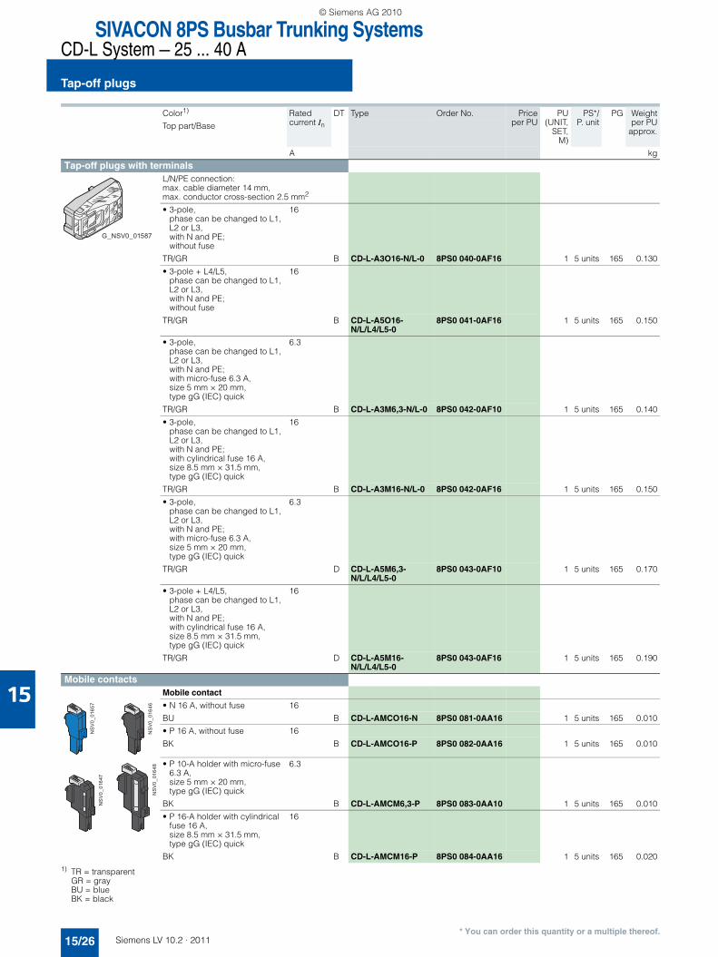
Tap-off plugs with terminalsL/N/PE connection: max. cable diameter 14 mm, max. conductor cross-section 2.5 mm2
• 3-pole, phase can be changed to L1, L2 or L3, with N and PE; without fuse
16
TR/GR B CD-L-A3O16-N/L-0 8PS0 040-0AF16 1 5 units 165 0.130
• 3-pole + L4/L5, phase can be changed to L1, L2 or L3, with N and PE; without fuse
16
TR/GR B CD-L-A5O16-N/L/L4/L5-0
8PS0 041-0AF16 1 5 units 165 0.150
• 3-pole, phase can be changed to L1, L2 or L3, with N and PE; with micro-fuse 6.3 A, size 5 mm × 20 mm, type gG (IEC) quick
6.3
TR/GR B CD-L-A3M6,3-N/L-0 8PS0 042-0AF10 1 5 units 165 0.140
• 3-pole, phase can be changed to L1, L2 or L3, with N and PE; with cylindrical fuse 16 A, size 8.5 mm × 31.5 mm, type gG (IEC) quick
16
TR/GR B CD-L-A3M16-N/L-0 8PS0 042-0AF16 1 5 units 165 0.150
• 3-pole, phase can be changed to L1, L2 or L3, with N and PE; with micro-fuse 6.3 A, size 5 mm × 20 mm, type gG (IEC) quick
6.3
TR/GR D CD-L-A5M6,3-N/L/L4/L5-0
8PS0 043-0AF10 1 5 units 165 0.170
• 3-pole + L4/L5, phase can be changed to L1, L2 or L3, with N and PE; with cylindrical fuse 16 A, size 8.5 mm × 31.5 mm, type gG (IEC) quick
16
TR/GR D CD-L-A5M16-N/L/L4/L5-0
8PS0 043-0AF16 1 5 units 165 0.190
Mobile contactsMobile contact
• N 16 A, without fuse 16
BU B CD-L-AMCO16-N 8PS0 081-0AA16 1 5 units 165 0.010
• P 16 A, without fuse 16
BK B CD-L-AMCO16-P 8PS0 082-0AA16 1 5 units 165 0.010
• P 10-A holder with micro-fuse 6.3 A, size 5 mm × 20 mm, type gG (IEC) quick
6.3
BK B CD-L-AMCM6,3-P 8PS0 083-0AA10 1 5 units 165 0.010
• P 16-A holder with cylindrical fuse 16 A, size 8.5 mm × 31.5 mm, type gG (IEC) quick
16
BK B CD-L-AMCM16-P 8PS0 084-0AA16 1 5 units 165 0.020
G_NSV0_01587
NS
V0_
0165
7
NS
V0_
0164
6
NS
V0_
0164
7
NS
V0_
0164
8
LV10-2_15_EN.book Seite 26 Mittwoch, 24. November 2010 11:06 11
© Siemens AG 2010
15
SIVACON 8PS Busbar Trunking SystemsCD-L System — 25 ... 40 A
Tap-off plugs
15/27Siemens LV 10.2 · 2011* You can order this quantity or a multiple thereof.
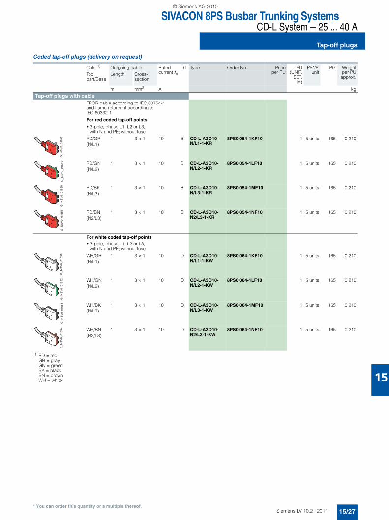
Coded tap-off plugs (delivery on request)
1) RD = red GR = gray GN = green BK = black BN = brown WH = white
Color1)
Top part/Base
Outgoing cable Rated current In
DT Type Order No. Priceper PU
PU(UNIT,
SET,M)
PS*/P.unit
PG Weightper PU
approx.Length Cross-
section
m mm2 A kg
Tap-off plugs with cableFROR cable according to IEC 60754-1 and flame-retardant according to IEC 60332-1
For red coded tap-off points
• 3-pole, phase L1, L2 or L3, with N and PE; without fuse
RD/GR(N/L1)
1 3 × 1 10 B CD-L-A3O10-N/L1-1-KR
8PS0 054-1KF10 1 5 units 165 0.210
RD/GN(N/L2)
1 3 × 1 10 B CD-L-A3O10-N/L2-1-KR
8PS0 054-1LF10 1 5 units 165 0.210
RD/BK(N/L3)
1 3 × 1 10 B CD-L-A3O10-N/L3-1-KR
8PS0 054-1MF10 1 5 units 165 0.210
RD/BN(N2/L3)
1 3 × 1 10 B CD-L-A3O10-N2/L3-1-KR
8PS0 054-1NF10 1 5 units 165 0.210
For white coded tap-off points
• 3-pole, phase L1, L2 or L3, with N and PE; without fuse
WH/GR(N/L1)
1 3 × 1 10 D CD-L-A3O10-N/L1-1-KW
8PS0 064-1KF10 1 5 units 165 0.210
WH/GN(N/L2)
1 3 × 1 10 D CD-L-A3O10-N/L2-1-KW
8PS0 064-1LF10 1 5 units 165 0.210
WH/BK(N/L3)
1 3 × 1 10 D CD-L-A3O10-N/L3-1-KW
8PS0 064-1MF10 1 5 units 165 0.210
WH/BN(N2/L3)
1 3 × 1 10 D CD-L-A3O10-N2/L3-1-KW
8PS0 064-1NF10 1 5 units 165 0.210
G_N
SV
0_01
658
G_N
SV
0_01
649
G_N
SV
0_01
650
G_N
SV
0_01
651
G_N
SV
0_01
659
G_N
SV
0_01
652
G_N
SV
0_01
653
G_N
SV
0_01
654
LV10-2_15_EN.book Seite 27 Mittwoch, 24. November 2010 11:06 11
© Siemens AG 2010

SIVACON 8PS Busbar Trunking SystemsCD-L System — 25 ... 40 A
Tap-off plugs
15/28 Siemens LV 10.2 · 2011
15
* You can order this quantity or a multiple thereof.
1) TR = transparent RD = red WH = white
Version Color1)
Top part/Base
Rated current In DT Type Order No. Priceper PU
PU(UNIT,
SET,M)
PS*/P. unit
PG Weightper PU
approx.
A kg
Tap-off plugs with terminalsL/N/PE connection: max. cable diameter 14 mm, max. conductor cross-section 2.5 mm2
For red coded tap-off points
• 3-pole, phase can be changed to L1, L2 or L3, with N and PE; without fuse
TR/RD 16 B CD-L-A3O16-N/L-KR-0
8PS0 050-0AF16 1 5 units 165 0.130
• 3-pole + L4/L5, phase can be changed to L1, L2 or L3, with N and PE; without fuse
TR/RD 16 D CD-L-A5O16-N/L/L4/L5-KR-0
8PS0 051-0AF16 1 5 units 165 0.150
• 3-pole, phase can be changed to L1, L2 or L3, with N and PE; with cylindrical fuse 16 A, size 8.5 mm × 31.5 mm, type gG (IEC) quick
TR/RD 16 B CD-L-A3M16-N/L-KR-0
8PS0 052-0AF16 1 5 units 165 0.150
• 3-pole + L4/L5, phase can be changed to L1, L2 or L3, with N and PE; with cylindrical fuse 16 A, size 8.5 mm × 31.5 mm, type gG (IEC) quick
TR/RD 16 D CD-L-A5M16-N/L/L4/L5-KR-0
8PS0 053-0AF16 1 5 units 165 0.190
For white coded tap-off points
• 3-pole, phase can be changed to L1, L2 or L3, with N and PE; without fuse
TR/WH 16 D CD-L-A3O16-N/L-KW-0
8PS0 065-0AF16 1 5 units 165 0.130
• 3-pole + L4/L5, phase can be changed to L1, L2 or L3, with N and PE; without fuse
TR/WH 16 D CD-L-A5O16-N/L/L4/L5-KW-0
8PS0 067-0AF16 1 5 units 165 0.150
• 3-pole, phase can be changed to L1, L2 or L3, with N and PE; with cylindrical fuse 16 A, size 8.5 mm × 31.5 mm, type gG (IEC) quick
TR/WH 16 B CD-L-A3M16-N/L-KW-0
8PS0 066-0AF16 1 5 units 165 0.150
• 3-pole + L4/L5, phase can be changed to L1, L2 or L3, with N and PE; with cylindrical fuse 16 A, size 8.5 mm × 31.5 mm, type gG (IEC) quick
TR/WH 16 D CD-L-A5M16-N/L/L4/L5-KW-0
8PS0 068-0AF16 1 5 units 165 0.190
G_NSV0_01590
G_NSV0_01624
LV10-2_15_EN.book Seite 28 Mittwoch, 24. November 2010 11:06 11
© Siemens AG 2010

15
SIVACON 8PS Busbar Trunking SystemsCD-L System — 25 ... 40 A
Accessories
15/29Siemens LV 10.2 · 2011* You can order this quantity or a multiple thereof.
■ Selection and ordering data
Number of sides Load capacity DT Type Order No. Priceper PU
PU(UNIT,
SET,M)
PS*/P. unit
PG Weightper PU
approx.
kg kg
Mounting Standard fixing bracketsFor mounting trunking units and luminaires
For mounting trunking units on the ceiling or floor and for suspending luminaires on the trunking unit
1 12 B CD-L-B1-G-12 8PS0 070-0AA00 1 12 units 165 0.030
2 12 B CD-L-B2-G-12 8PS0 073-0AA00 1 12 units 165 0.040
Universal suspension bracketsFor mounting trunking units and luminaires
For suspending trunking units on the wall, on the ceiling or on the floor and for sus-pending luminaires on the trunking unit
1 25 B CD-L-B1-O-25 8PS0 072-0AA00 1 12 units 165 0.050
2 25 B CD-L-B2-O-25 8PS0 075-0AA00 1 12 units 165 0.060
Fixing brackets with hook For mounting trunking units and luminaires
For suspension by cable or pendant or chain and for suspending the luminaires on the trunking unit
1 25 B CD-L-BH1-25 8PS0 085-0AA00 1 12 units 165 0.030
2 25 B CD-L-BH2-25 8PS0 086-0AA00 1 12 units 165 0.040
Hooks, open and closedFor mounting trunking units and luminaires
For suspension by cable or pendant or chain in conjunction with suspension/fixing bracket
• Hook open 25 B CD-L-HO 8PS0 076-0AA00 100 12 units 165 1.000
• Hook closed 25 B CD-L-HG 8PS0 077-0AA00 100 12 units 165 1.000
NS
V0_
0159
1N
SV
0_01
592
NS
V0_
0159
3N
SV
0_01
594
LV10-2_15_EN.book Seite 29 Mittwoch, 24. November 2010 11:06 11
© Siemens AG 2010

SIVACON 8PS Busbar Trunking SystemsCD-L System — 25 ... 40 A
Accessories
15/30 Siemens LV 10.2 · 2011
15
* You can order this quantity or a multiple thereof.
Version DT Type Order No. Priceper PU
PU(UNIT,
SET,M)
PS*/P.unit
PG Weightper PU
approx.
kg
Cable ducts Cable ductsMade of plastic (white), standard length 3 m.
Cable duct used for cables in auxiliary circuits.
It is mounted on the trunking unit with the fixing brackets for cable ducts (two brack-ets every 3 m).
B CD-L-CC 8PS0 087-0AA00 1 6 units 165 0.025
Fixing brackets for cable ductFixing bracket for cable duct for mounting the cable ducts on the ceiling, on the floor or on the wall, alone or in combination with trunking units
It can be mounted on the standard fixing brackets or universal suspension brack-ets.
B CD-L-BCCO 8PS0 088-0AA00 1 12 units 165 0.040
Accessories for degree of protection IP55 IP55 covers for tap-off point B CD-L-FAS 8PS0 080-0AA00 1 12 units 165 0.010
G_NSV0_01595
G_NSV0_01596
G_NSV0_01597
LV10-2_15_EN.book Seite 30 Mittwoch, 24. November 2010 11:06 11
© Siemens AG 2010

SIVACON 8PS Busbar Trunking SystemsBD01 System — 40 ... 160 A
Introduction
15/31Siemens LV 10.2 · 2011
15
■ Overview
Version
Type-tested low-voltage switchgear and controlgear combina-tion (TTA) according to• IEC/EN 60439-1• IEC/EN 60439-2
Degree of protection• High degree of protection IP54 with tap-off points at sides and
bottom• Degree of protection IP50 with tap-off points at the top• Degree of protection increase to IP55 with optional equipment
Components
Trunking units• 5-conductor system• 2 or 3 tap-off units spaced 1 m apart• 4 or 6 tap-off units spaced 0.5 m apart• Lengths of 2 m and 3 m
Junction units• Flexible junction units
Feeder units• Universal infeed
Tap-off units• Up to 63 A• With built-in parts or for customized device installation• For 3, 4 or 8 modular widths (MW)• With or without device installation unit
Ancillary equipment units• For 4 or 8 modular widths (MW)• With or without device installation unit• With or without socket assembly
Accessories• Mounting sets for degree of protection IP55• Fixing and suspending• Coding sets• Fire protection kit S90
NSV0_00041a
1
2
3
4
4
4
6
5
123456
Trunking unit
Feeder unitJunction unit
Tap-off unitAncillary equipment unitOptional equipment
LV10-2_15_EN.book Seite 31 Mittwoch, 24. November 2010 11:06 11
© Siemens AG 2010

SIVACON 8PS Busbar Trunking SystemsBD01 System — 40 ... 160 A
Introduction
15/32 Siemens LV 10.2 · 2011
15
* You can order this quantity or a multiple thereof.
■ Benefits
• Flexible power supply• Easy and quick planning• Time-saving mounting• Reliable mechanical and electrical connection technology• High stability, low weight• Few basic modules required• Storage-friendly system• Variable change of the direction of the busbar line• Versatile tap-off units• Positive opening and closing of tap-off points• Accessories for increasing the degree of protection to IP55 for
extreme ambient conditions
■ Selection and ordering data
Trunking units
Rated current Length Tap-off points DT Type Order No. Priceper PU
PU(UNIT,
SET, M)
PS*/P. unit
PG Weightper PU
approx.Number Spacing
A m m kg
Trunking unitsWith joint block, sheet-steel enclosure, color similar to RAL 7035 (light gray), codable tap-off points
40 3 6 0.5 A BD01-40-3-0,5 BVP:034253 1 1 unit 165 4.350
3 1 A BD01-40-3-1 BVP:233551 1 1 unit 165 4.350
2 4 0.5 A BD01-40-2-0,5 BVP:034254 1 1 unit 165 3.000
2 1 A BD01-40-2-1 BVP:233552 1 1 unit 165 3.000
63 3 6 0.5 A BD01-63-3-0,5 BVP:034255 1 1 unit 165 4.600
3 1 A BD01-63-3-1 BVP:233553 1 1 unit 165 4.600
2 4 0.5 A BD01-63-2-0,5 BVP:034256 1 1 unit 165 3.200
2 1 A BD01-63-2-1 BVP:233555 1 1 unit 165 3.200
100 3 6 0.5 A BD01-100-3-0,5 BVP:034257 1 1 unit 165 5.200
3 1 A BD01-100-3-1 BVP:233556 1 1 unit 165 5.200
2 4 0.5 A BD01-100-2-0,5 BVP:034258 1 1 unit 165 3.600
2 1 A BD01-100-2-1 BVP:233557 1 1 unit 165 3.600
125 3 6 0.5 A BD01-125-3-0,5 BVP:090163 1 1 unit 165 5.200
3 1 A BD01-125-3-1 BVP:233559 1 1 unit 165 5.200
2 4 0.5 A BD01-125-2-0,5 BVP:090161 1 1 unit 165 3.600
2 1 A BD01-125-2-1 BVP:233560 1 1 unit 165 3.600
160 3 6 0.5 A BD01-160-3-0,5 BVP:090164 1 1 unit 165 8.000
3 1 A BD01-160-3-1 BVP:233563 1 1 unit 165 8.000
2 4 0.5 A BD01-160-2-0,5 BVP:090162 1 1 unit 165 5.400
2 1 A BD01-160-2-1 BVP:233567 1 1 unit 165 5.400
NS
V0_
0024
1
LV10-2_15_EN.book Seite 32 Mittwoch, 24. November 2010 11:06 11
© Siemens AG 2010

15
SIVACON 8PS Busbar Trunking SystemsBD01 System — 40 ... 160 A
Junction unitsFeeder units
15/33Siemens LV 10.2 · 2011* You can order this quantity or a multiple thereof.
■ Selection and ordering data
Use plastic cable glands with strain relief (not included in scope of supply).1) Use M32, M40 or M50 cable glands.2) Use M63 cable glands.
Rated current Length DT Type Order No. Priceper PU
PU(UNIT,
SET, M)
PS*/P. unit
PG Weightper PU
approx.
A m kg
Junction unitsFlexible junction units with joint block
100 0.5 A BD01-R1 BVP:034260 1 1 unit 165 1.200
1 A BD01-R2 BVP:034261 1 1 unit 165 2.050
160 0.5 A BD01-160-R1 BVP:090166 1 1 unit 165 1.750
1 A BD01-160-R2 BVP:090167 1 1 unit 165 3.050
NS
V0_
0027
4
Rated current Conductor cross-section
DT Type Order No. Priceper PU
PU(UNIT,
SET, M)
PS*/P. unit
PG Weightper PU
approx.
A mm2 kg
Feeder unitsMolded-plastic enclosures, with 2 end flangesCan be fitted at all connection ter-minals and the busbar run ends, can be combined with BD01-GK... ancillary equipment units
• 6 cable entries from 4 sides
100 50 1) A BD01-E BVP:034259 1 1 unit 165 1.000
• Cable entry from 2 sides
160 95 2) A BD01-160-E BVP:090165 1 1 unit 165 1.400
NS
V0_
0024
2N
SV
0_00
243
LV10-2_15_EN.book Seite 33 Mittwoch, 24. November 2010 11:06 11
© Siemens AG 2010

SIVACON 8PS Busbar Trunking SystemsBD01 System — 40 ... 160 A
Tap-off units for international use
15/34 Siemens LV 10.2 · 2011* You can order this quantity or a multiple thereof.
15
■ Selection and ordering data
Fuse links are not included in scope of supply.
Use plastic cable glands with strain relief (not included in scope of supply).
Rated current Rated operational voltage
DT Type Order No. Priceper PU
PU(UNIT,
SET, M)
PS*/P. unit
PG Weightper PU
approx.
A V kgTap-off units, molded plastic, size 01
With protective lower section for 1 cylindrical fuse 10 mm × 38 mm
16 400 A BD01-AK01X/ZS BVP:087483 1 1 unit 165 0.300Tap-off units, molded plastic, size 02
With protective lower section for 3 cylindrical fuses 10 mm × 38 mm
32 400 A BD01-AK02X/ZS3 BVP:085090 1 1 unit 165 0.400
Tap-off units, molded plastic, size 02, with device installation unit
With 3-pole miniature circuit breaker 16 A, characteristic B
• Without socket outlet
16 400 A BD01-AK02M0/A163 BVP:085089 1 1 unit 165 0.800
• With 1 CEE socket outlet 16 A, 5-pole
16 400 A BD01-AK02M0/CEE165A163
BVP:085092 1 1 unit 165 0.980
With 3-pole miniature circuit breaker 32 A, characteristic C
32 400 A BD01-AK02M0/A323 BVP:085094 1 1 unit 165 0.800
NS
V0_
0024
4
NS
V0_
0024
5N
SV
0_00
246
NS
V0_
0024
7
NS
V0_
0024
6
LV10-2_15_EN.book Seite 34 Mittwoch, 24. November 2010 11:06 11
© Siemens AG 2010
15
SIVACON 8PS Busbar Trunking SystemsBD01 System — 40 ... 160 A
Tap-off units for international use
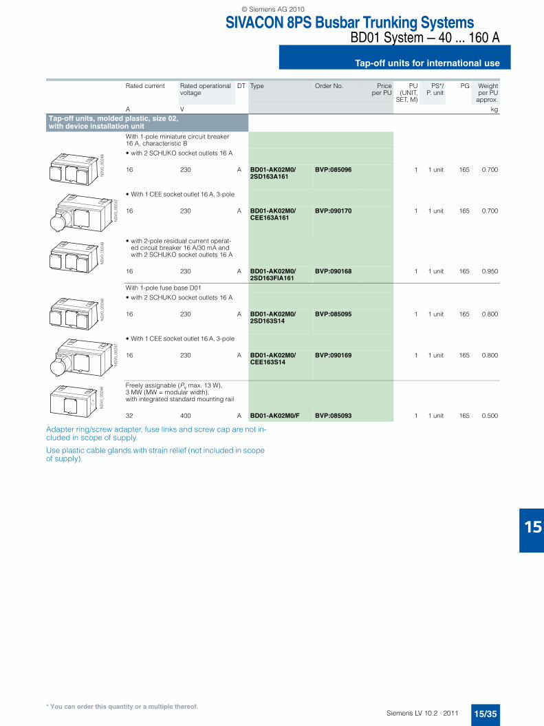
15/35Siemens LV 10.2 · 2011* You can order this quantity or a multiple thereof.
Adapter ring/screw adapter, fuse links and screw cap are not in-cluded in scope of supply.
Use plastic cable glands with strain relief (not included in scope of supply).
Rated current Rated operational voltage
DT Type Order No. Priceper PU
PU(UNIT,
SET, M)
PS*/P. unit
PG Weightper PU
approx.
A V kgTap-off units, molded plastic, size 02, with device installation unit
With 1-pole miniature circuit breaker 16 A, characteristic B
• with 2 SCHUKO socket outlets 16 A
16 230 A BD01-AK02M0/ 2SD163A161
BVP:085096 1 1 unit 165 0.700
• With 1 CEE socket outlet 16 A, 3-pole
16 230 A BD01-AK02M0/CEE163A161
BVP:090170 1 1 unit 165 0.700
• with 2-pole residual current operat-ed circuit breaker 16 A/30 mA and with 2 SCHUKO socket outlets 16 A
16 230 A BD01-AK02M0/ 2SD163FIA161
BVP:090168 1 1 unit 165 0.950
With 1-pole fuse base D01
• with 2 SCHUKO socket outlets 16 A
16 230 A BD01-AK02M0/ 2SD163S14
BVP:085095 1 1 unit 165 0.800
• With 1 CEE socket outlet 16 A, 3-pole
16 230 A BD01-AK02M0/CEE163S14
BVP:090169 1 1 unit 165 0.800
Freely assignable (Pv max. 13 W), 3 MW (MW = modular width), with integrated standard mounting rail
32 400 A BD01-AK02M0/F BVP:085093 1 1 unit 165 0.500
NS
V0_
0024
8
NS
V0_
0024
7
NS
V0_
0024
8N
SV
0_00
248
NS
V0_
0024
7
NS
V0_
0024
6
LV10-2_15_EN.book Seite 35 Mittwoch, 24. November 2010 11:06 11
© Siemens AG 2010

SIVACON 8PS Busbar Trunking SystemsBD01 System — 40 ... 160 A
Tap-off units for international use
15/36 Siemens LV 10.2 · 2011
15
* You can order this quantity or a multiple thereof.
Adapter ring/screw adapter, fuse links and screw cap are not in-cluded in scope of supply.
Use plastic cable glands with strain relief (not included in scope of supply).
Rated current Rated operational voltage
DT Type Order No. Priceper PU
PU(UNIT,
SET, M)
PS*/P. unit
PG Weightper PU
approx.
A V kgTap-off units, aluminum, size 1
With 1-pole fuse base D01
• with 2 SCHUKO socket outlets 16 A
16 230 A BD01-AK1X/ 2SD163S14
BVP:034268 1 1 unit 165 1.400
• With 1 CEE socket outlet 16 A, 3-pole
16 230 A BD01-AK1X/ CEE163S14
BVP:034270 1 1 unit 165 1.380
With 3-pole fuse base 3 × D01
16 400 A BD01-AK1X/S14 BVP:034264 1 1 unit 165 1.400
With 3-pole fuse base 3 × D02
35 400 A BD01-AK1X/S18 BVP:034265 1 1 unit 165 1.400
With 1-pole miniature circuit breaker 16 A, characteristic B
• with 2 SCHUKO socket outlets 16 A
16 230 A BD01-AK1X/ 2SD163A161
BVP:034269 1 1 unit 165 1.470
• With 1 CEE socket outlet 16 A, 3-pole
16 230 A BD01-AK1X/ CEE163A161
BVP:034271 1 1 unit 165 1.435
Freely assignable (Pv max. 13 W), 4 MW (MW = modular width), with integrated standard mounting rail
35 400 A BD01-AK1X/F BVP:034272 1 1 unit 165 1.000
NS
V0_
0025
0N
SV
0_00
251
NS
V0_
0024
9N
SV
0_00
249
NS
V0_
0025
0N
SV
0_00
251
NS
V0_
0024
9
LV10-2_15_EN.book Seite 36 Mittwoch, 24. November 2010 11:06 11
© Siemens AG 2010

15
SIVACON 8PS Busbar Trunking SystemsBD01 System — 40 ... 160 A
Tap-off units for international use
15/37Siemens LV 10.2 · 2011* You can order this quantity or a multiple thereof.
Use plastic cable glands with strain relief (not included in scope of supply).
Rated current Rated operational voltage
DT Type Order No. Priceper PU
PU(UNIT,
SET, M)
PS*/P. unit
PG Weightper PU
approx.
A V kgTap-off units, aluminum, size 1, with device installation unit
With 3 x 1-pole miniature circuit breaker 10 A, characteristic B
10 400 A BD01-AK1M1/A101 BVP:203098 1 1 unit 165 1.600
With 3 x 1-pole miniature circuit breaker 16 A, characteristic B
16 400 A BD01-AK1M1/A161 BVP:034266 1 1 unit 165 1.600
With 3-pole miniature circuit breaker 32 A, characteristic C
32 400 A BD01-AK1M1/A323 BVP:034267 1 1 unit 165 1.600
Freely assignable (Pv max. 13 W), 4 MW (MW = modular width), with integrated standard mounting rail
35 400 A BD01-AK1M1/F BVP:034273 1 1 unit 165 1.000
NS
V0_
0025
2N
SV
0_00
252
NS
V0_
0025
2N
SV
0_00
253
LV10-2_15_EN.book Seite 37 Mittwoch, 24. November 2010 11:06 11
© Siemens AG 2010

SIVACON 8PS Busbar Trunking SystemsBD01 System — 40 ... 160 A
Tap-off units for international use
15/38 Siemens LV 10.2 · 2011
15
* You can order this quantity or a multiple thereof.
Adapter ring/screw adapter, fuse links and screw cap are not in-cluded in scope of supply.
Use plastic cable glands with strain relief (not included in scope of supply).
Rated current Rated operational voltage
DT Type Order No. Priceper PU
PU(UNIT,
SET, M)
PS*/P. unit
PG Weightper PU
approx.
A V kgTap-off units, aluminum, size 2
With 3-pole fuse base S27/S33
• With 3-pole fuse base S27, gauge screw system
25 400 A BD01-AK2X/S27 BVP:034274 1 1 unit 165 1.700
• With 3-pole fuse base S33, gauge screw system
63 400 A BD01-AK2HX/S33 BVP:233568 1 1 unit 165 1.700
With 2 × 1-pole fuse base D01 and with 4 SCHUKO socket outlets 16 A
16 230 A BD01-AK2X/ 4SD163S14
BVP:034277 1 1 unit 165 2.000
With 3 × 1-pole fuse base D01 and with 1 CEE socket outlet 16 A, 5-pole
16 400 A BD01-AK2X/ CEE165S14
BVP:034279 1 1 unit 165 1.850
With 3 × 1-pole fuse base D02 and with 1 CEE socket outlet 32 A, 5-pole
32 400 A BD01-AK2X/ CEE325S18
BVP:034281 1 1 unit 165 2.000
With 2 × 1-pole miniature circuit breaker 16 A, characteristic B, and with 4 SCHUKO socket outlets 16 A
16 230 A BD01-AK2X/ 4SD163A161
BVP:034278 1 1 unit 165 2.100
Freely assignable, 8 MW (MW = mod-ular width), with integrated standard mounting rail
• Freely assignable (Pv max. 16 W)
35 400 A BD01-AK2X/F BVP:034283 1 1 unit 165 1.300
• Freely assignable (Pv max. 22.5 W)
63 400 A BD01-AK2HX/F BVP:233570 1 1 unit 165 1.300
NS
V0_
0025
4N
SV
0_00
255
NS
V0_
0025
6N
SV
0_00
256
NS
V0_
0025
5N
SV
0_00
254
LV10-2_15_EN.book Seite 38 Mittwoch, 24. November 2010 11:06 11
© Siemens AG 2010

15
SIVACON 8PS Busbar Trunking SystemsBD01 System — 40 ... 160 A
Tap-off units for international use
15/39Siemens LV 10.2 · 2011* You can order this quantity or a multiple thereof.
Use plastic cable glands with strain relief (not included in scope of supply).
Rated current Rated operational voltage
DT Type Order No. Priceper PU
PU(UNIT,
SET, M)
PS*/P. unit
PG Weightper PU
approx.
A V kgTap-off units, aluminum, size 2, with device installation unit
With 1-pole miniature circuit breaker 16 A, characteristic B, with 2-pole residual current operated circuit breaker 16 A/30 mA and with 2 SCHUKO socket outlets 16 A
16 230 A BD01-AK2M1/ 2SD163FIA161
BVP:034276 1 1 unit 165 2.000
With 1-pole miniature circuit breaker 16 A, characteristic C, with 2-pole residual current operated circuit breaker 25 A/30 mA and with 1 CEE socket outlet 16 A,3-pole
16 400 A BD01-AK2M1/ CEE163FIA161
BVP:660867 1 1 unit 165 2.000
With 3-pole miniature circuit breaker 16 A, characteristic C, with 4-pole residual current operated circuit breaker 25 A/30 mA and with 1 CEE socket outlet 16 A,5-pole
16 400 A BD01-AK2M2/ CEE165FIA163
BVP:660866 1 1 unit 165 3.500
With 3-pole miniature circuit breaker 16 A, characteristic C, and with 1 CEE socket outlet 16 A, 5-pole
16 400 A BD01-AK2M1/ CEE165A163
BVP:034280 1 1 unit 165 2.000
With 3-pole miniature circuit breaker 32 A, characteristic C, and with 1 CEE socket outlet 32 A, 5-pole
32 400 A BD01-AK2M1/ CEE325A323
BVP:034282 1 1 unit 165 2.100
Freely assignable, 8 MW (MW = modular width), with integrated standard mounting rail
• Freely assignable (Pv max. 16 W)
35 400 A BD01-AK2M2/F BVP:034284 1 1 unit 165 1.360
• Freely assignable (Pv max. 22.5 W)
63 400 A BD01-AK2HM2/F BVP:233571 1 1 unit 165 1.360
NS
V0_
0025
7N
SV
0_00
258
NS
V0_
0147
3
NS
V0_
0025
8N
SV
0_00
258
NS
V0_
0025
9
LV10-2_15_EN.book Seite 39 Mittwoch, 24. November 2010 11:06 11
© Siemens AG 2010

SIVACON 8PS Busbar Trunking SystemsBD01 System — 40 ... 160 A
Ancillary equipment units for international use
15/40 Siemens LV 10.2 · 2011* You can order this quantity or a multiple thereof.
15
■ Selection and ordering data
Ancillary equipment units are supplied with the cable gland for housing connection.
Use plastic cable glands with strain relief (not included in scope of supply).
Version Rated operational voltage
DT Type Order No. Priceper PU
PU(UNIT,
SET,M)
PS*/P. unit
PG Weightper PU
approx.
V kgAncillary equipment units, aluminum, size 1
Freely assignable (Pv max. 13 W), 4 MW (MW = modular width), with integrated standard mounting rail
Can be used for• Surge suppressors• Remote control/remote
switching• Intelligence
400 A BD01-GK1X/F BVP:034285 1 1 unit 165 0.800
with 4 SCHUKO socket out-lets 16 A
400 A BD01-GK1X/4SD163 BVP:034287 1 1 unit 165 1.200
With 1 CEE socket outlet 16 A, 3-pole
400 A BD01-GK1X/CEE163 BVP:660808 1 1 unit 165 0.950
With 1 CEE socket outlet 16 A, 5-pole
400 A BD01-GK1X/CEE165 BVP:660809 1 1 unit 165 1.000
With 1 CEE socket outlet 32 A, 5-pole
400 A BD01-GK1X/CEE325 BVP:660810 1 1 unit 165 1.040
Ancillary equipment units, size 1, with device installation unitFreely assignable (Pv max. 13 W), 4 MW (MW = modular width), with integrated standard mounting rail
Can be used for• Remote control/remote
switching• Intelligence• Component mounting unit
for mounting components, e.g. miniature circuit breakers
400 A BD01-GK1M1/F BVP:034286 1 1 unit 165 0.800
NS
V0_
0026
0N
SV
0_00
261
NS
V0_
0147
4N
SV
0_01
474
NS
V0_
0147
4N
SV
0_00
262
LV10-2_15_EN.book Seite 40 Mittwoch, 24. November 2010 11:06 11
© Siemens AG 2010

15
SIVACON 8PS Busbar Trunking SystemsBD01 System — 40 ... 160 A
Ancillary equipment units for international use
15/41Siemens LV 10.2 · 2011* You can order this quantity or a multiple thereof.
Ancillary equipment units are supplied with the cable gland for housing connection.
Use plastic cable glands with strain relief (not included in scope of supply).
Version Rated operational voltage
DT Type Order No. Priceper PU
PU(UNIT,
SET,M)
PS*/P. unit
PG Weightper PU
approx.
V kgAncillary equipment units, aluminum, size 2
Freely assignable (Pv max. 16 W), 8 MW (MW = modular width), with integrated standard mounting rail
Can be used for• Surge suppressors• Remote control/remote
switching• Intelligence
400 A BD01-GK2X/F BVP:034288 1 1 unit 165 1.100
With 2 SCHUKO socket outlets 16 A and 1 CEE socket outlet, 16 A, 5-pole
400 A BD01-GK2X/2SD163CEE165
BVP:034291 1 1 unit 165 1.600
With 2 SCHUKO socket outlets 16 A and 1 CEE socket outlet, 32 A, 5-pole
400 A BD01-GK2X/2SD163CEE325
BVP:660811 1 1 unit 165 1.800
With 1 CEE socket outlet 16 A, 3-pole, and 1 CEE socket outlet 16 A, 5-pole
400 A BD01-GK2X/CEE163CEE165
BVP:034290 1 1 unit 165 1.500
Ancillary equipment units, size 2, with device installation unit
Freely assignable (Pv max. 16 W), 8 MW (MW = modular width), with integrated standard mounting rail
Can be used for• Remote control/remote
switching• Intelligence• Component mounting unit
for mounting components, e.g. miniature circuit breakers
400 A BD01-GK2M2/F BVP:034289 1 1 unit 165 1.100
NS
V0_
0026
3N
SV
0_00
264
NS
V0_
0026
4N
SV
0_00
265
NS
V0_
0026
6
LV10-2_15_EN.book Seite 41 Mittwoch, 24. November 2010 11:06 11
© Siemens AG 2010

SIVACON 8PS Busbar Trunking SystemsBD01 System — 40 ... 160 A
Accessories
15/42 Siemens LV 10.2 · 2011* You can order this quantity or a multiple thereof.
15
■ Selection and ordering data
Version DT Type Order No. Priceper PU
PU(UNIT,
SET, M)
PS*/P. unit
PG Weightper PU
approx.
kgAccessories for degree of protection IP55
For tap-off points A BD01-FAS BVP:610363 1 5 units 165 0.100
For connection points A BD01-FS BVP:610362 1 5 units 165 0.150
For feeder units
• Mounting position at the bottom A BD01-FES BVP:610364 1 1 unit 165 0.150
• Mounting position at the side or top A BD01-KS BVP:611057 1 1 unit 165 0.030
NSV0_00978
NSV0_00979
NSV0_00980
NSV0_00981
LV10-2_15_EN.book Seite 42 Mittwoch, 24. November 2010 11:06 11
© Siemens AG 2010

15
SIVACON 8PS Busbar Trunking SystemsBD01 System — 40 ... 160 A
Accessories
15/43Siemens LV 10.2 · 2011* You can order this quantity or a multiple thereof.
Version DT Type Order No. Priceper PU
PU(UNIT,
SET, M)
PS*/P. unit
PG Weightper PU
approx.
kgAccessories for degree of protection IP55
For tap-off units
• Size 01X, 02X Size 01 A BD01-AK01X-IP55 BVP:610365 1 1 unit 165 0.050
Size 02 A BD01-AK02X-IP55 BVP:610366 1 1 unit 165 0.050
• Size 1X, 2X Size 1 A BD01-AK1X-IP55 BVP:610367 1 1 unit 165 0.050
Size 2 A BD01-AK2X-IP55 BVP:610368 1 1 unit 165 0.050Fire protection
Fire protection kits for mounting by the customer with fire protection plates and fixing screws
A BD01-S90 BVP:611354 1 1 unit 165 1.500
Fire protection approval kits(required only for Germany)
A BD01-S90-ZUL-D BVP:611373 1 1 unit 165 0.200
Accessories for degree of protection IP55, for tap-off units size 1X, 2X
NSV0_00982
NS
V0_
0098
3
Accessories for degree of protection IP55, for tap-off units size 01X, 02X
NS
V0_
0146
0
Fire protection kit
LV10-2_15_EN.book Seite 43 Mittwoch, 24. November 2010 11:06 11
© Siemens AG 2010

SIVACON 8PS Busbar Trunking SystemsBD01 System — 40 ... 160 A
Accessories
15/44 Siemens LV 10.2 · 2011
15
* You can order this quantity or a multiple thereof.
Version Rated current Ie
DT Type Order No. Priceper PU
PU(UNIT,
SET, M)
PS*/P. unit
PG Weightper PU
approx.
A kgMounting
Universal fixing brackets A BD01-B BVP:034262 1 1 unit 165 0.167
Suspension brackets A BD01-BA BVP:081945 1 1 unit 165 0.167
Hanger brackets • For suspension by cable or pendant
chain• At the connection point
A BD01-BAP BVP:203522 1 1 unit 165 0.576
Mounting partsEnd flanges A BD01-EF BVP:611071 1 1 unit 165 0.300
Joint blocks 100 D BD01-100-KB BVP:201966 1 1 unit 165 0.350
160 D BD01-160-KB BVP:201967 1 1 unit 165 0.350
CodingCoding sets• 4 coding positions
A BD01-K BVP:034263 1 10 units 165 0.010
NS
V0_
0027
5
NS
V0_
0027
6
NS
V0_
0027
7
NS
V0_
0098
5N
SV
0_00
984
NS
V0_
0027
8
LV10-2_15_EN.book Seite 44 Mittwoch, 24. November 2010 11:06 11
© Siemens AG 2010