Buried Pipe Corrosion in the Power Plant Environment · PDF fileBuried Pipe Corrosion in the...
50
Buried Pipe Corrosion in the Power Plant Environment Assessment and Mitigation in Nuclear Power Plants IAEA Technical Meeting on Buried Pipe October 15, 2014 Kurt M. Lawson Mears Group, Inc.
Transcript of Buried Pipe Corrosion in the Power Plant Environment · PDF fileBuried Pipe Corrosion in the...

Buried Pipe Corrosion in the Power
Plant Environment
Assessment and Mitigation in Nuclear Power Plants
IAEA Technical Meeting on Buried Pipe
October 15, 2014
Kurt M. Lawson
Mears Group, Inc.

Topics
Background
Buried Pipe Corrosion
Problems in the Plant Environment
Combined Approach to Asset Integrity
2

Formed in 1970 and acquired By Quanta Services in 2000.
Mears Group is comprised of:
Mears Horizontal Directional Drilling (HDD)
Mears Integrity Solutions
> Inline Devices
11 Offices Worldwide: U.S, Canada, Abu Dhabi, Malaysia, Australia and India.

MEARS
Quanta Services • NYSE: PWR
• Member: S&P 500 Index
• Market Cap: $4.5 Billion
• 35 Operating Entities
• 17,000 Employees
• Electric Power
• Pipeline Infrastructure
• Telecommunications

Global Reach
Australia
Belize
Brazil
British Virgin Islands
Canada
Costa Rica
Guam
Guatemala
Honduras
India
Indonesia
Iraq
Liberia
Luxembourg
Mexico
Netherlands
Nicaragua
Panama
Peru
Republic of Chad
South Africa
Trinidad
United Arab Emirates
Venezuela
Countries where Quanta has a permanent office or has worked.
Quanta has
successfully completed
projects that are local,
regional, national and
international in scope

Buried Pipe Corrosion
An electrochemical process governed by electrical laws
NACE International
“The deterioration of a metal as a result of a reaction with its environment”

IRON OXIDE BLAST FURNACE BESSEMER
PIPE MILL STEEL PIPE
PIPE CORRODING IRON OXIDE
REFINING PROCESS
CORROSION PROCESS
Energy – The Life Cycle of Steel
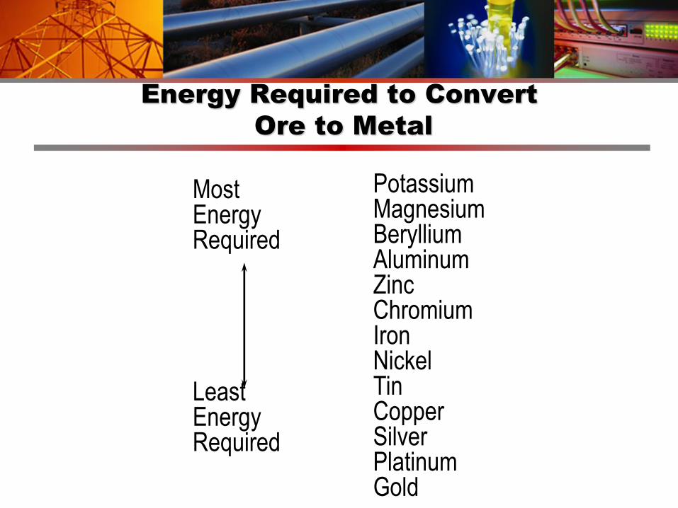
Most Energy Required Least Energy Required
Potassium Magnesium Beryllium Aluminum Zinc Chromium Iron Nickel Tin Copper Silver Platinum Gold
Energy Required to Convert
Ore to Metal

ELECTROMOTIVE SERIES
Neutral Soil
Material V, (Cu/CuSO4)
Mg (Galvomag Alloy) -1.75
Mg (H-1 Alloy) -1.55
Zn -1.1
Al (Alclad 3S) -1.0
Cast Iron -0.5
Lead -0.5
Mild Steel (Clean) -0.2 to –0.8
Mild Steel (Rusted) -0.2 to –0.5
Mild Steel (in Concrete) -0.2
Copper -0.2
High Silicon Cast Iron -0.2
Stainless Steel (Type 304) -0.15 to –0.6
Carbon (Graphite, Coke) +0.3

CORROSION CELLS
Requirements
Anode
Cathode
Electrolyte Shared by Anode and Cathode (Soil)
Metallic or Electron Path between Anode and Cathode

CORROSION CELLS
Dry Cell Battery
Zinc Carbon
NH4Cl Solution
Zn+2
H2
+
-

Graphite-Zinc Battery
-
Zinc Case
(Anode)
+
Zn+2
Carbon
Rod
(cathode)
NH4Cl Solution
I

CAUSES OF CORROSION
Differential Soil Aeration
Differential Soil Chemistry
Dissimilar Metals Contact
Stray Current
Microbiological

Challenges in the Plant Environment
In a plant (world) there is really no such thing as a non-corrosive soil
Galvanic effects
Complex piping CONFIGURATIONS
Electrically discontinuous piping

Corrosivity of Soils
Corrosivity of a particular soil is based on the interaction of several parameters: Resistivity
Dissolved salts,
Moisture content,
pH
Presence of Bacteria,
Amount of oxygen, and
Others

Cathodic Protection Challenges in the
Plant Environment
Complex Piping
Current Distribution
Monitoring
Deep Piping
Monitoring
Galvanic Issues
Current Distribution
Monitoring
Geometry
Current Distribution

Complex Piping

Galvanic issues with Reinforcing Steel

Geometry and Grounding

Material V, (Cu/CuSO4)
Mg (Galvomag Alloy) -1.75
Mg (H-1 Alloy) -1.55
Zn -1.1
Al (Alclad 3S) -1.0
Cast Iron -0.5
Lead -0.5
Mild Steel (Clean) -0.2 to –0.8
Mild Steel (Rusted) -0.2 to –0.5
Mild Steel (in Concrete) -0.2
Copper -0.2
High Silicon Cast Iron -0.2
Stainless Steel (Type 304) -0.15 to –0.6
Carbon (Graphite, Coke) +0.3
ELECTROMOTIVE SERIES
Neutral Soil

Role of Electrical Grounding
Three Important Functions
Personnel Safety from Electrical Faults
Lightning Protection
Termination Point for Instrumentation Shields
Accomplished Through
Direct Buried Copper Cables and Vertical Ground Rods
> In Grids
> In Longitudinal Runs
> Around perimeter of Buildings/Pedestals
3

Impact on Corrosion
Grounding Comprised of Copper Material
Plant Piping/Buried Structures
Carbon Steel
Cast/Ductile Iron
Stainless Steel
Copper/Aluminum Bronze
Reinforced Concrete
Pre/Post tensioned Concrete
7

Impact of Grounding on Corrosion
Driving Force For Corrosion = Voltage Difference
Voltage or Potential
An electromotive force, or a difference in potential expressed in volts.
Voltage is the energy that puts charges in motion.
8

Piping Corrosion Rates in Soils
(Uhlig/Romanoff)
Environmental
Factors
General Corrosion Rates, mpy Pitting Corrosion Rates, mpy
Maximum Minimum Average Maximum Minimum Average
Soil Resistivity
Less Than 1,000 2.5 0.7 1.3 12.2 4.3 7.9
1,000 to 5,000 2.3 0.2 0.7 17.7 2.0 5.5
5,000 to 12,000 1.3 0.2 0.7 9.1 2.4 5.5
Greater Than
12,0001.4 0.1 0.6 10.2 1.2 4.3
Drainage
Very Poor 2.3 1.5 1.8 17.7 6.3 11.0
Poor 1.5 0.4 0.9 9.1 2.0 5.5
Fair 2.5 0.7 0.9 12.2 3.1 6.3
10

Impact of Grounding on Corrosion of
Buried Steel Piping
No Copper Couple to Steel
Steel Corrodes at 2- 10 mils/yr (1000ths of inch/year)
Copper/Steel Area Ratio = 1
Steel Corrosion Accelerates by 3x Factor
Copper/Steel Area Ratio = 10
Steel Corrosion Accelerates by 10x Factor
Copper/Steel Area Ratio = 20
Steel Corrosion Accelerates by 30x Factor
11

CP Current Distribution in a Power Plant
Because the interconnection of Low Resistance Grounding Systems
with High Resistance Piping Systems
Majority of CP current goes to bare copper grounding
27

Combined Approach to Asset Integrity
Assess
Analyze
Mitigate

Assessments
Inspection Results
With attention to locations
Cathodic Protection Annual Surveys
Galvanic Corrosion
Soil Corrosivity
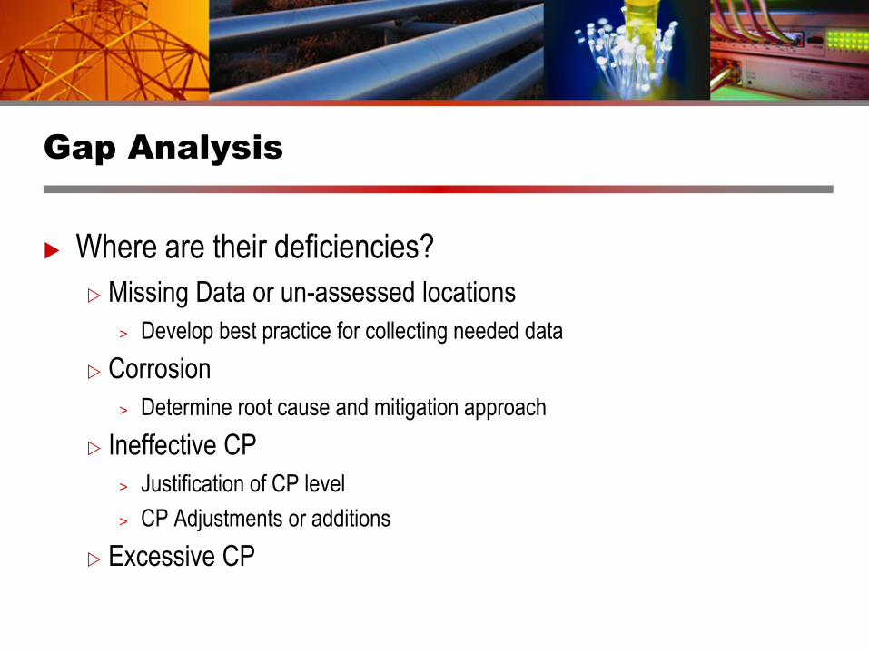
Gap Analysis
Where are their deficiencies?
Missing Data or un-assessed locations
> Develop best practice for collecting needed data
Corrosion
> Determine root cause and mitigation approach
Ineffective CP
> Justification of CP level
> CP Adjustments or additions
Excessive CP
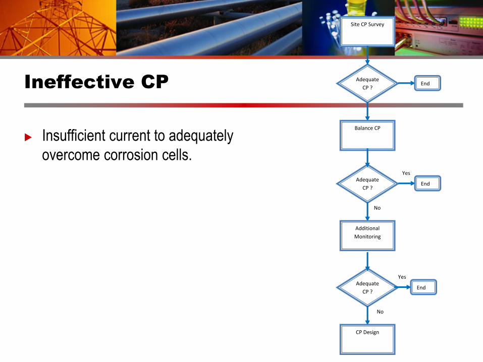
Ineffective CP
Insufficient current to adequately
overcome corrosion cells.
Site CP Survey
Adequate
CP ? End
Balance CP
Adequate
CP ?
Yes
No
End
Additional
Monitoring
Adequate
CP ?
Yes
No
End
CP Design

Determining the
Effectiveness of CP
Practical application makes use of structure-to-electrolyte
potentials.
Effective cathodic protection is achieved if NACE Criteria are
satisfied.

Applicable NACE Standards
SP0169 Control of External Corrosion on Underground or Submerged Metallic Piping Systems
SP0285 Corrosion Control of Underground Storage Tank Systems by Cathodic Protection
SP0193 External Cathodic Protection of On-Grade Metallic Storage Tank Bottoms
SP0290 Cathodic Protection of Reinforcing Steel in Atmospherically Exposed Structures
TM0497 Measurement Techniques Related to Criteria for Cathodic Protection on Underground or
Submerged Metallic Piping Systems

Criteria for Underground or
Submerged Iron or Steel Structures
–0.850 VCSE potential--Negative (cathodic) potential of at least 850 mVCSE with
the cathodic protection applied after IR drop is considered
–0.850 VCSE polarized potential--Negative polarized potential of at least 850
mVCSE
100 mV polarization--Minimum of 100 mV of cathodic polarization
• Note: These are specific to carbon steel and lower
temperatures.

Time
Structure-to-Electrolyte Potential
Po
ten
tial (
-mV
)
(+)
( )
ON Potential
OFF Potential
IRIR
Native (Free Corroding, Static) Potential
100 mV
Polarization
100 mV Depolarization
“ON-IR” -850 mVCSE
“OFF” -850 mVCSE
Po
ten
tial (
-mV
)
(+)
( )
ON Potential
OFF Potential
IRIR
Native (Free Corroding, Static) Potential
100 mV
Polarization
100 mV Depolarization
“ON-IR” -850 mVCSE
“OFF” -850 mVCSE

Notes to Criteria
In the presence of bacteria or elevated temperatures, the criteria may not
be sufficient.
In well aerated, well drained soils, corrosion protection may be achieved at
less negative potentials.

Criteria and Grounding
SP0169 6.2.5 Dissimilar Metal Piping:
“A negative voltage between all pipe surfaces and a stable reference electrode
contacting the electrolyte equal to that required for the protection of the most
anodic metal should be maintained.”
Measuring 100mV of polarization based upon mixed potential of a
steel/copper couple may not result in adequate protection of the more
anodic (steel) material.
No true ‘native’ carbon steel potentials exist?

Coupon Test Stations
Coupon Test Stations
Evaluate -850 mV Polarized Potential
Problem Areas
> IR voltage drop error
> Multiple rectifier interruption
> Non-interruptible stray current sources
> Directly connected sacrificial anodes
> Multiple pipeline potential averaging

Typical Installation

40
1. Freely Corroding Coupon
2. Coupon Bonded to Structure/Grounding
3. Energize CP
4-7. Adjustments to CP System

ER Coupons
Corrosion Rate Coupons/Stations
Provides both CP related information and Corrosion Rate Data
Electrical Resistance (ER)
change in resistance of a metal element as it corrodes
Where:
> R = Resistance
> ρ = Resistivity
> L = Length
> A = Cross sectional area
A
LR

ER Coupons - Continued
ER – Continued
Requires many measurements to provide statistical significance
Does not distinguish between general or localized corrosion

ER Coupons - Response time vs. probe life

LPR (Electrochemical) Coupons
Utilizes electrochemical measurements for direct instantaneous
measurement of corrosion rate
Linear Polarization Resistance

LPR theory – Stern-Geary Relationship
corcacor
ca
appapp
pi
B
iidi
dR
3.2
00
Formula uses absolute values of anodic and cathodic
DFn
MimpyCR cor248.1)(
icor – mA/m2 D – density, g/cm3
M – molecular weight, g/mole F=96,490 coulomb/eq
n- number of electrons transferred (valence)

Test Methods:
Polarization – LPR – Sources of Error
Tafel constants unknown
Reasonable estimate 0.100-0.120V for both a and c
Relative comparison (based on Rp) is accurate
Oxidation reactions other than corrosion
If other oxidizing species are present (sulfides, calculated corrosion current will be overestimated
Typically not a concern for soils
Non-steady-state conditions (time issues)

Test Methods:
Polarization – LPR measurements
LPR measures “instantaneous” corrosion rate
Can be used for continuous corrosion monitoring
Can be used for periodic assessment of corrosion state
Used extensively in high resistivity conditions, such as soils, concrete, non-aqueous environments
Cannot determine corrosion rate of cathodically protected surface

Corrosion Rates
Utilize Linear Polarization Resistance (LPR) for Soil Corrosivity studies
Native (un-polarized coupon)
Defensible and Conservative rate

Excessive CP
Unnecessary Consumption of CP Materials
Coating Damage
Cathodic Disbondment
Overprotection of Amphoteric Materials
Lead, Zinc, Aluminum
Titanium Hydriding
Hydrogen Damage to High Strength Materials
Bolts
PCCP

Summary
We have many tools to assist in properly
maintaining buried structures
Utilize all tools in a layered process to
leverage cost savings and ensure integrity
of buried assets
Assess
Analyze
Mitigate
27
Site CP Survey
Adequate
CP ? End
Balance CP
Adequate
CP ?
Yes
No
End
Additional
Monitoring
Adequate
CP ?
Yes
No
End
CP Design