Buckling Failures in Insect Exoskeletons
14
1 Buckling Failures in Insect Exoskeletons Eoin Parle, Simona Herbaj, Fiona Sheils, Hannah Larmon and David Taylor Trinity Centre for Bioengineering Trinity College Dublin Dublin 2 Ireland Corresponding author: David Taylor phone: +353 18961703; email: [email protected]
Transcript of Buckling Failures in Insect Exoskeletons
1
Buckling Failures in Insect Exoskeletons
Eoin Parle, Simona Herbaj, Fiona Sheils, Hannah Larmon and David Taylor Trinity Centre for Bioengineering Trinity College Dublin Dublin 2 Ireland Corresponding author: David Taylor phone: +353 18961703; email: [email protected]
2
Abstract Thin-walled tubes loaded in bending are prone to failure by buckling. It is difficult to predict the loading conditions which cause buckling, especially for tubes of non-standard cross section. Insights into buckling prevention might be gained by studying this phenomenon in the exoskeletons of insects and other arthropods. We investigated the leg segments (tibiae) of five different insects: the locust (Schistocerca gergaria), american cockroach (Periplaneta americana), death’s head cockroach (Blaberus discoidalis), stick insect (Parapachymorpha zomproi) and bumblebee (Bombus terrestris audax). These were tested to failure in cantilever bending and modelled using finite element analysis (FEA). The tibiae of the locust and the cockroaches were found to be approximately circular in shape. Their buckling loads were well predicted by linear elastic FEA, and also by one of the analytical solutions available in the literature for elastic buckling. The legs of the stick insect are also circular in cross section but have several prominent longitudinal ridges. We hypothesised that these ridges might protect the legs against buckling but we found that this was not the case: the loads necessary for elastic buckling were not reached in practice because yield occurred in the material, causing plastic buckling. The legs of bees have a non-circular cross section due to a pollen-carrying feature (the corbicula). We found that this did not significantly affect their resistance to buckling. Keywords Buckling; failure; exoskeleton; insect Introduction Many structures and components are made from slender, thin-walled hollow tubes. This is often done to reduce weight (e.g. in aircraft), and for other design considerations: for example long, slender devices such as catheters and laparoscopic equipment. Under load, a tube may suddenly collapse by buckling, a mode of failure which is notoriously difficult to predict at the design stage. Elastic buckling occurs at stresses less than the yield strength or fracture stress of the material and is characterised by a condition of instability with respect to deformation in some direction. In Euler buckling, for example, a column loaded in axial compression becomes unstable with respect to transverse displacements. The present paper is concerned with buckling phenomena which occur when a tube is loaded in bending. In this case two different phenomena can occur, known as local buckling and ovalisation buckling. Local buckling can arise in any thin plate structure experiencing compressive stress: out-of-plane displacements occur giving rise to localised kinks in the plate. In ovalisation buckling an initially circular tube becomes oval in shape as a result of applied bending loads: this type of deformation becomes unstable at a critical bending moment (Brazier, 1927). Even for the relatively simple case of a tube of circular cross section and constant wall thickness, loaded in pure bending,, it is difficult to accurately predict the onset of buckling. Analytical solutions often differ significantly from experimental results: see for example (Timoshenko and Gere, 1961) and (Rees, 1997). For a tube of radius r and thickness t made from a material with Young’s modulus E and Poisson’s ratio
, the critical bending moment Mb for both local buckling and ovalisation buckling can be described by the following equation:
3
2
2
1
ErtMb (1)
Assuming a thin-walled tube (t<<r) and a Poisson’s ratio of 0.3, the maximum stress in the tube at this bending moment is given by:
r
tEb (2)
The constants in these two equations, and , have been assigned different values by different workers
in the past. For example several textbooks (e.g. (Timoshenko and Gere, 1961)) quote a value of =0.605. However NASA conducted an extensive investigation, comparing theoretical and experimental data for a wide range of tube dimensions and materials (NASA, 1968). They proposed that this constant should be lower, and should vary with r/t, having a value of 0.525 for r/t=10 (the lowest r/t value considered), decreasing slightly to 0.500 for r/t=20. Wadee et al developed a computer simulation for a tube in pure bending: they predicted that local buckling would occur before ovalisation buckling and found a value of
=0.542 for r/t-=10. Calladine proposed a much lower value of 0.313 in his analysis, which predicted local buckling whilst taking account of the change in shape caused by ovalisation (Calladine, 1983). Thus even for this relatively simple case the literature gives values for the critical buckling load which vary by almost a factor of 2. For more complex cases it may be appropriate to use finite element analysis (FEA). A simple linear elastic analysis will not predict buckling. Many commercial FE packages have special routines for detecting elastic instability; aAlternatively, it may be possible to simulate buckling by using the facility of FE packages to accommodate large deflections using iterative analysis to detect geometric nonlinearities, i.e. non-linear force-deflection relationships which occur due to significant changes in the shape of the body during loading.
For some combinations of geometry and material properties b will be higher than the yield strength or fracture stress of the material, in which case failure will occur by yielding or fracture before elastic buckling. For stresses close to this critical value the two modes of buckling and yielding/fracture may interact. It can be shown that an optimal strength to weight ratio is achieved when these two modes of failure are equally likely; Wegst and Ashby developed this analysis for the case of materials with orthotropic mechanical properties and applied it to plant stems (Wegst and Ashby, 2007). In a previous paper (Taylor and Dirks, 2012) we applied this approach to two arthropod limb segments, the hind tibia of the locust and the merus of the blue crab, showing in both cases that the r/t ratio was close to the predicted optimum value. The exoskeletons of insects are made from a material known as cuticle, which consists of fibres of chitin in a matrix of proteins and polysaccrides. The same type of material is also found in other arthropods such as crabs and lobsters, where it also contains mineral particles. Arthropod cuticle is an extremely common material, the second most common natural material after wood, but to date there have been very few studies of its mechanical behaviour. Some workers have measured material properties such as Young’s modulus, tensile strength and fracture toughness using samples from various insect body parts (Jensen and Weis-Fogh, 1962; Sun and Tong, 2007; Ker, 1977; Dirks and Taylor, 2012b; Dirks and Taylor, 2012a). Apart from our previous paper (Taylor and Dirks, 2012) there has been no work on buckling failures, though one review mentions the fact that some body parts have ridges which might resist Euler buckling (Vincent and Wegst, 2004). The primary mode of loading for insect legs is bending, as a result of ground reaction forces during activities such as walking and jumping (Sutton and Burrows, 2008).
4
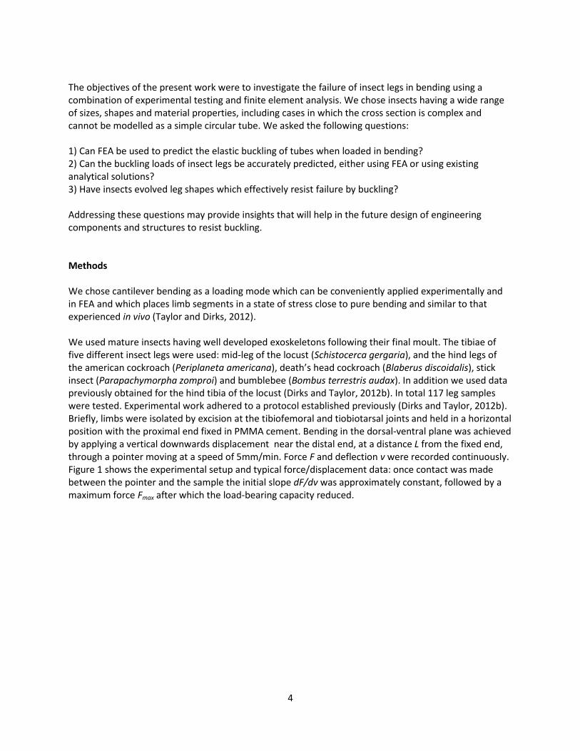
The objectives of the present work were to investigate the failure of insect legs in bending using a combination of experimental testing and finite element analysis. We chose insects having a wide range of sizes, shapes and material properties, including cases in which the cross section is complex and cannot be modelled as a simple circular tube. We asked the following questions: 1) Can FEA be used to predict the elastic buckling of tubes when loaded in bending? 2) Can the buckling loads of insect legs be accurately predicted, either using FEA or using existing analytical solutions? 3) Have insects evolved leg shapes which effectively resist failure by buckling? Addressing these questions may provide insights that will help in the future design of engineering components and structures to resist buckling. Methods We chose cantilever bending as a loading mode which can be conveniently applied experimentally and in FEA and which places limb segments in a state of stress close to pure bending and similar to that experienced in vivo (Taylor and Dirks, 2012). We used mature insects having well developed exoskeletons following their final moult. The tibiae of five different insect legs were used: mid-leg of the locust (Schistocerca gergaria), and the hind legs of the american cockroach (Periplaneta americana), death’s head cockroach (Blaberus discoidalis), stick insect (Parapachymorpha zomproi) and bumblebee (Bombus terrestris audax). In addition we used data previously obtained for the hind tibia of the locust (Dirks and Taylor, 2012b). In total 117 leg samples were tested. Experimental work adhered to a protocol established previously (Dirks and Taylor, 2012b). Briefly, limbs were isolated by excision at the tibiofemoral and tiobiotarsal joints and held in a horizontal position with the proximal end fixed in PMMA cement. Bending in the dorsal-ventral plane was achieved by applying a vertical downwards displacement near the distal end, at a distance L from the fixed end, through a pointer moving at a speed of 5mm/min. Force F and deflection v were recorded continuously. Figure 1 shows the experimental setup and typical force/displacement data: once contact was made between the pointer and the sample the initial slope dF/dv was approximately constant, followed by a maximum force Fmax after which the load-bearing capacity reduced.
5
Figure 1: Experimental set up and typical results from the cantilever bending test on an insect tibia: the applied
force is plotted as function of the displacement of loading pointer. Once the pointer makes contact with the sample there is an initial, approximately linear region with a slope dF/dV from which Young’s modulus can be
calculated. Failure is defined as occurring at the maximum stress Fmax.
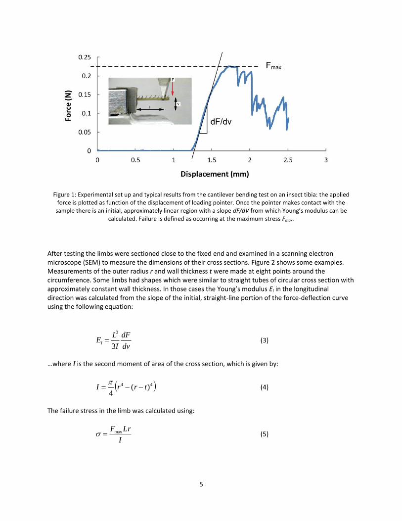
After testing the limbs were sectioned close to the fixed end and examined in a scanning electron microscope (SEM) to measure the dimensions of their cross sections. Figure 2 shows some examples. Measurements of the outer radius r and wall thickness t were made at eight points around the circumference. Some limbs had shapes which were similar to straight tubes of circular cross section with approximately constant wall thickness. In those cases the Young’s modulus El in the longitudinal direction was calculated from the slope of the initial, straight-line portion of the force-deflection curve using the following equation:
dv
dF
I
LEl
3
3
(3)
…where I is the second moment of area of the cross section, which is given by:
44 )(4
trrI
(4)
The failure stress in the limb was calculated using:
I
LrFmax (5)
6
Figure 2: Scanning electron microscope photographs showing typical cross sections of insect tibia. The locust and cockroach tibiae had approximately circular cross sections (typified here by the example of the locust mid leg). The
stick insect had five prominent ridges running longitudinally along the leg. The bee had one large, flat surface which is used for pollen collection.
7
For those limbs having non-circular shapes (the stick insect and bee) the Young’s modulus was found by making FE models and comparing the predicted and experimental slope values dF/dv. All FEA was carried out using ANSYS software: material was assumed to be linear elastic and isotropic. Poisson’s ratio was assumed to be 0.3. Using the “Large Deflections” option allowed us to model the nonlinear behaviour which is caused by locally high distortions that occur during buckling. The size of mesh elements and the number of iteration steps in the analysis were varied until convergence occurred. For the buckling predictions, both using the equations and the FEA, material anisotropy was incorporated as proposed by Wegst and Ashby (2007), by replacing E in equations 1 and 2 with (ElEt)
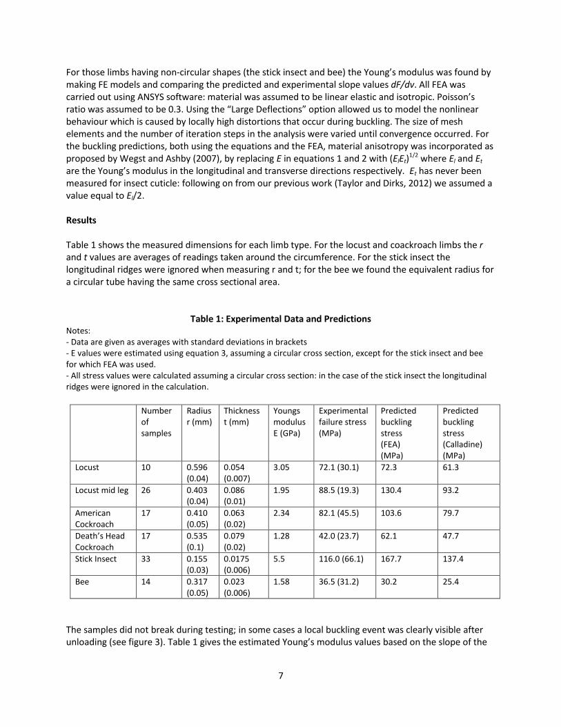
1/2 where El and Et are the Young’s modulus in the longitudinal and transverse directions respectively. Et has never been measured for insect cuticle: following on from our previous work (Taylor and Dirks, 2012) we assumed a value equal to El/2. Results Table 1 shows the measured dimensions for each limb type. For the locust and coackroach limbs the r and t values are averages of readings taken around the circumference. For the stick insect the longitudinal ridges were ignored when measuring r and t; for the bee we found the equivalent radius for a circular tube having the same cross sectional area.
Table 1: Experimental Data and Predictions Notes: - Data are given as averages with standard deviations in brackets - E values were estimated using equation 3, assuming a circular cross section, except for the stick insect and bee for which FEA was used. - All stress values were calculated assuming a circular cross section: in the case of the stick insect the longitudinal ridges were ignored in the calculation.
Number of samples
Radius r (mm)
Thickness t (mm)
Youngs modulus E (GPa)
Experimental failure stress (MPa)
Predicted buckling stress (FEA) (MPa)
Predicted buckling stress (Calladine) (MPa)
Locust 10 0.596 (0.04)
0.054 (0.007)
3.05 72.1 (30.1) 72.3 61.3
Locust mid leg 26 0.403 (0.04)
0.086 (0.01)
1.95 88.5 (19.3) 130.4 93.2
American Cockroach
17 0.410 (0.05)
0.063 (0.02)
2.34 82.1 (45.5) 103.6 79.7
Death’s Head Cockroach
17 0.535 (0.1)
0.079 (0.02)
1.28 42.0 (23.7) 62.1 47.7
Stick Insect 33 0.155 (0.03)
0.0175 (0.006)
5.5 116.0 (66.1) 167.7 137.4
Bee 14 0.317 (0.05)
0.023 (0.006)
1.58 36.5 (31.2) 30.2 25.4
The samples did not break during testing; in some cases a local buckling event was clearly visible after unloading (see figure 3). Table 1 gives the estimated Young’s modulus values based on the slope of the
8
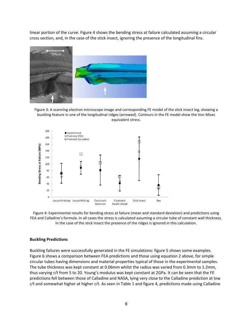
linear portion of the curve. Figure 4 shows the bending stress at failure calculated assuming a circular cross section, and, in the case of the stick insect, ignoring the presence of the longitudinal fins.
Figure 3: A scanning electron microscope image and corresponding FE model of the stick insect leg, showing a
buckling feature in one of the longitudinal ridges (arrowed). Contours in the FE model show the Von Mises equivalent stress.
Figure 4: Experimental results for bending stress at failure (mean and standard deviation) and predictions using
FEA and Calladine’s formula. In all cases the stress is calculated assuming a circular tube of constant wall thickness. In the case of the stick insect the presence of the ridges is ignored in this calculation.
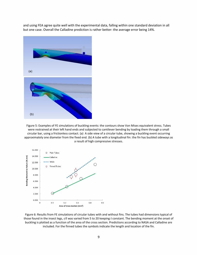
Buckling Predictions Buckling failures were successfully generated in the FE simulations: figure 5 shows some examples. Figure 6 shows a comparison between FEA predictions and those using equation 2 above, for simple circular tubes having dimensions and material properties typical of those in the experimental samples. The tube thickness was kept constant at 0.06mm whilst the radius was varied from 0.3mm to 1.2mm, thus varying r/t from 5 to 20. Young’s modulus was kept constant at 2GPa. It can be seen that the FE predictions fell between those of Calladine and NASA, lying very close to the Calladine prediction at low r/t and somewhat higher at higher r/t. As seen in Table 1 and figure 4, predictions made using Calladine
9
and using FEA agree quite well with the experimental data, falling within one standard deviation in all but one case. Overall the Calladine prediction is rather better: the average error being 14%.
Figure 5: Examples of FE simulations of buckling events: the contours show Von Mises equivalent stress. Tubes were restrained at their left hand ends and subjected to cantilever bending by loading them through a small circular bar, using a frictionless contact. (a) A side view of a circular tube, showing a buckling event occurring
approximately one diameter from the fixed end. (b) A tube with a longitudinal fin: the fin has buckled sideways as a result of high compressive stresses.
Figure 6: Results from FE simulations of circular tubes with and without fins. The tubes had dimensions typical of
those found in the insect legs, r/t was varied from 5 to 20 keeping t constant. The bending moment at the onset of buckling is plotted as a function of the area of the cross section. Predictions according to NASA and Calladine are
included. For the finned tubes the symbols indicate the length and location of the fin.
10
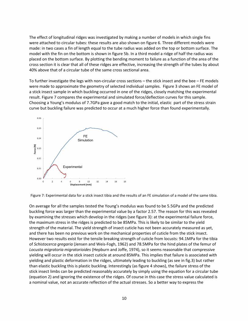
The effect of longitudinal ridges was investigated by making a number of models in which single fins were attached to circular tubes: these results are also shown on figure 6. Three different models were made: in two cases a fin of length equal to the tube radius was added on the top or bottom surface. The model with the fin on the bottom is shown in figure 5b. In a third model a ridge of half the radius was placed on the bottom surface. By plotting the bending moment to failure as a function of the area of the cross section it is clear that all of these ridges are effective, increasing the strength of the tubes by about 40% above that of a circular tube of the same cross sectional area. To further investigate the legs with non-circular cross sections – the stick insect and the bee – FE models were made to approximate the geometry of selected individual samples. Figure 3 shows an FE model of a stick insect sample in which buckling occurred in one of the ridges, closely matching the experimental result. Figure 7 compares the experimental and simulated force/deflection curves for this sample. Choosing a Young’s modulus of 7.7GPa gave a good match to the initial, elastic part of the stress strain curve but buckling failure was predicted to occur at a much higher force than found experimentally.
Figure 7: Experimental data for a stick insect tibia and the results of an FE simulation of a model of the same tibia.
On average for all the samples tested the Young’s modulus was found to be 5.5GPa and the predicted buckling force was larger than the experimental value by a factor 2.57. The reason for this was revealed by examining the stresses which develop in the ridges (see figure 3): at the experimental failure force, the maximum stress in the ridges is predicted to be 85MPa. This is likely to be similar to the yield strength of the material. The yield strength of insect cuticle has not been accurately measured as yet, and there has been no previous work on the mechanical properties of cuticle from the stick insect. However two results exist for the tensile breaking strength of cuticle from locusts: 94.1MPa for the tibia of Schistocerca gregaria (Jensen and Weis-Fogh, 1962) and 78.5MPa for the hind plates of the femur of Locusta migratoria migratorioides (Hepburn and Joffe, 1974), so it seems reasonable that compressive yielding will occur in the stick insect cuticle at around 85MPa. This implies that failure is associated with yielding and plastic deformation in the ridges, ultimately leading to buckling (as see in fig.3) but rather than elastic buckling this is plastic buckling. Interestingly (as figure 4 shows), the failure stress of the stick insect limbs can be predicted reasonably accurately by simply using the equation for a circular tube (equation 2) and ignoring the existence of the ridges. Of course in this case the stress value calculated is a nominal value, not an accurate reflection of the actual stresses. So a better way to express the
11
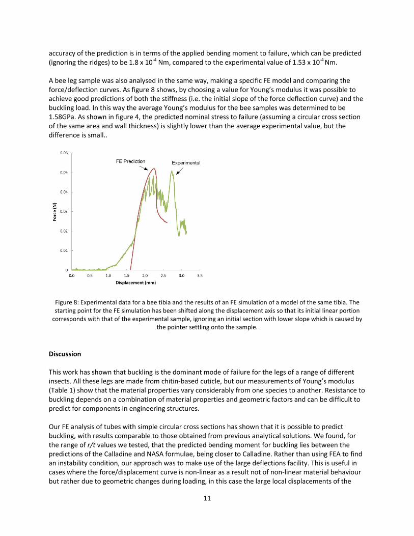
accuracy of the prediction is in terms of the applied bending moment to failure, which can be predicted (ignoring the ridges) to be 1.8 x 10⁻⁴ Nm, compared to the experimental value of 1.53 x 10⁻⁴ Nm. A bee leg sample was also analysed in the same way, making a specific FE model and comparing the force/deflection curves. As figure 8 shows, by choosing a value for Young’s modulus it was possible to achieve good predictions of both the stiffness (i.e. the initial slope of the force deflection curve) and the buckling load. In this way the average Young’s modulus for the bee samples was determined to be 1.58GPa. As shown in figure 4, the predicted nominal stress to failure (assuming a circular cross section of the same area and wall thickness) is slightly lower than the average experimental value, but the difference is small..
Figure 8: Experimental data for a bee tibia and the results of an FE simulation of a model of the same tibia. The starting point for the FE simulation has been shifted along the displacement axis so that its initial linear portion
corresponds with that of the experimental sample, ignoring an initial section with lower slope which is caused by the pointer settling onto the sample.
Discussion This work has shown that buckling is the dominant mode of failure for the legs of a range of different insects. All these legs are made from chitin-based cuticle, but our measurements of Young’s modulus (Table 1) show that the material properties vary considerably from one species to another. Resistance to buckling depends on a combination of material properties and geometric factors and can be difficult to predict for components in engineering structures. Our FE analysis of tubes with simple circular cross sections has shown that it is possible to predict buckling, with results comparable to those obtained from previous analytical solutions. We found, for the range of r/t values we tested, that the predicted bending moment for buckling lies between the predictions of the Calladine and NASA formulae, being closer to Calladine. Rather than using FEA to find an instability condition, our approach was to make use of the large deflections facility. This is useful in cases where the force/displacement curve is non-linear as a result not of non-linear material behaviour but rather due to geometric changes during loading, in this case the large local displacements of the
12
tube wall in the region where buckling eventually occurs. The type of testing used - cantilever bending – gives a maximum bending moment at the fixed end of the sample, however buckling is prevented from occurring here by the restraint applied, so buckling occurs a short distance from the fixed end, approximately one diameter away (see figs 3 and 5). The success of the FE approach in this case is very useful because it implies that FE modelling can also be used to investigate more complex cases such as tubes with fins and non-circular cross sections. We found that adding a single fin to a circular tube increased the resistance to buckling significantly when compared to a circular tube having the same cross sectional area. This is not surprising since the fin was placed in the plane of bending. A slightly non-intuitive finding was that it is better to place the fin on the top surface, i.e. on the side experiencing tensile stress, rather than on the bottom surface where the buckling event actually occurs (see figure 6). These results would imply that the longitudinal ridges on stick insect legs have evolved to prevent buckling, however our results suggest otherwise. Whilst this would be the case if the material behaved elastically (figure 7) premature failure occurs, probably as a result of the onset of plastic deformation, causing a visible, permanent buckling event in one of the fins (figure 3). This raises the question: “What is the purpose of these ridges?” Another possible mechanical purpose would be to increase stiffness: the legs of the stick insect are very long and slender, and will tend to deflect considerably even under forces which will not cause them to fail. Excessive deflection could prevent the legs from functioning correctly. We found that the addition of these ridges increased the stiffness of the leg by approximately a factor of three. However, this is achieved at the expense of adding a considerable amount of material to the cross section (see fig.2). If the extra material were to be used instead to make a circular tube of larger radius, this would have increased the stiffness by about a factor of four. So it seems that the use of these ridges is not an optimal way of increasing stiffness. It is likely that they have evolved to serve some other purpose, perhaps not a mechanical one. The non-circular shape of the bee leg, having one large flat face, would appear to be disadvantageous as regards buckling, however we found this was not the case. Even though we loaded the leg with the flat side uppermost, thus giving it the smallest moment of inertia for the cross section, the bending moment required for buckling was very similar to that predicted for a circular cross section of the same area and thickness (see fig.4) and this similarity was confirmed with an accurate FE model of this cross section. This shows that non-circular cross sections can be developed without sacrificing strength when buckling is the dominant failure mode.
A very simple formula, equation 2 with a constant equal to 0.313 as proposed by Calladine, is able to give reasonably accurate predictions of the buckling strength for all insect legs tested, even though none of them is perfectly circular and some have very non-circular cross sections. In the case of the stick insect the longitudinal ridges were ignored in this calculation; the success of the Calladine formula in this case is clearly fortuitous since we have shown that the mode of failure is not elastic buckling anyway. Finite element analysis using a non-linear material model would be needed to make accurate predictions. Apart from this case, elastic buckling was found to be responsible for all failures. These findings are useful because they help us to understand how these body parts have evolved, and what factors in the material properties and morphology are relevant. For example, the fact that failure occurs by elastic buckling rather than by plastic yielding or brittle fracture, means that the relevant material property is Young’s modulus, rather than the yield strength or fracture toughness. It also informs the discussion regarding the geometry and dimensions of exoskeletal body parts: such parts will have
13
relatively large diameters, compared to endoskeletons, which means that inevitably they will be quite thin-walled (to reduce weight), giving them the kinds of shapes for which buckling is a significant risk. Conclusions In this work we tested the tibiae of several different species of insect and showed that the mode of failure was buckling, a type of failure which is also common in engineering structures. We drew the following conclusions: 1. Elastic buckling of circular tubes loaded in bending can be simulated using finite element analysis, using the “large deflections” mode. For the range of r/t values considered here the predictions are similar to those of Calladine, who incorporated ovalisation into a prediction of local buckling. 2. The tibiae of locusts and cockroaches are approximately circular tubes of constant wall thickness. Cantilever bending causes elastic buckling which can be predicted using FEA or Calladine’s formula. 3. The tibiae of stick insects have prominent longitudinal ridges which would appear to be useful to increase stiffness and prevent buckling, however this turns out not to be the case because high stresses in the ridges cause failure by plastic buckling. This demonstrates how material properties and geometry can interact in complex ways, which must be taken into account when designing thin-walled tubes. 4. The tibiae of bees have a triangular cross section featuring a large flat side for pollen collection. This does not significantly affect the bending moment to failure, showing that non-circular cross sections can be designed without compromising mechanical strength. Acknowledgements We would like to acknowledge the expert advice of Prof Jane Stout (Botany Department, Trinity College Dublin), our Zoology Department for provision of insect housing facilities and our Centre for Microscopy and Analysis for assistance with the scanning electron microscopy work.
Reference List
Brazier,L.G. (1927) Proceedings of the Royal Society of London 116, 104.
Calladine,C.R. (1983) Theory of Shell Structures. Cambridge University Press, Cambridge, UK.
Dirks,J.-H. and Taylor,D. (2012a) Veins improve fracture toughness of insect wings. PLoS ONE 7, e43411.
Dirks,J.H. and Taylor,D. (2012b) Fracture toughness of locust cuticle. Journal of Experimental Biology 215, 1502-1508.
Hepburn,H.R. and Joffe,I. (1974) Locust solid cuticle - a time sequence of mechanical properties. Journal of Insect Physiology 20, 497-506.
14
Jensen,M. and Weis-Fogh,T. (1962) Biology and physics of locust flight V. strength and elasticity of locust cuticle. Phil.Trans.Roy.Soc.London B, Biological Sciences 245, 137-169.
Ker,R.F. (1977) Some Structural and Mechanical Properties of Locust and Beetle Cuticle. PhD University of Oxford.
NASA (1968) Buckling of thin-walled circular cylinders (NASA SP-8007). NASA (USA).
Rees,D.W.A. (1997) Basic Solid Mechanics.
Sun,J.Y. and Tong,J. (2007) Fracture Toughness Properties of Three Different
Biomaterials Measured by Nanoindentation. Journal of Bionic Engineering 4, 11-17.
Sutton,G.P. and Burrows,M. (2008) The mechanics of elevation control in locust jumping. Journal of Comparative Physiology A 194, 557-563.
Taylor,D. and Dirks,J.H. (2012) Shape optimization in exoskeletons and endoskeletons: A biomechanics analysis. Journal of the Royal Society Interface 9, 3480-3489.
Timoshenko,S. and Gere,J.M. (1961) Theory of Elastic Stability 2nd Edition. New York.
Vincent,J.F.V. and Wegst,U.G.K. (2004) Design and mechanical properties of insect cuticle. Arthropod Structure and Development 33, 187-199.
Wegst,U.G.K. and Ashby,M.F. (2007) The structural efficiency of orthotropic stalks, stems and tubes. Journal of Materials Science 42, 9005-9014.