Bridging Team Efforts Supporting Current & Future Forces
31
Bridging Team Efforts Supporting Current & Future Forces Brian K. Hornbeck Deputy Associate Director, Force Projection Technology COMM (586) 574-5608 or DSN 786-5608 Gov Phone: 586-216-5213 NIPR: [email protected] UNCLAS: Dist A. Approved for Public Release
Transcript of Bridging Team Efforts Supporting Current & Future Forces

Bridging Team Efforts Supporting
Current & Future Forces
Brian K. HornbeckDeputy Associate Director, Force Projection Technology
COMM (586) 574-5608 or DSN 786-5608
Gov Phone: 586-216-5213
NIPR: [email protected] UNCLAS: Dist A. Approved for Public Release
Report Documentation Page Form ApprovedOMB No. 0704-0188
Public reporting burden for the collection of information is estimated to average 1 hour per response, including the time for reviewing instructions, searching existing data sources, gathering andmaintaining the data needed, and completing and reviewing the collection of information. Send comments regarding this burden estimate or any other aspect of this collection of information,including suggestions for reducing this burden, to Washington Headquarters Services, Directorate for Information Operations and Reports, 1215 Jefferson Davis Highway, Suite 1204, ArlingtonVA 22202-4302. Respondents should be aware that notwithstanding any other provision of law, no person shall be subject to a penalty for failing to comply with a collection of information if itdoes not display a currently valid OMB control number.
1. REPORT DATE 08 APR 2009
2. REPORT TYPE N/A
3. DATES COVERED -
4. TITLE AND SUBTITLE Bridging Team Efforts Supporting Current & Future Forces
5a. CONTRACT NUMBER
5b. GRANT NUMBER
5c. PROGRAM ELEMENT NUMBER
6. AUTHOR(S) Brian K. Hornbeck
5d. PROJECT NUMBER
5e. TASK NUMBER
5f. WORK UNIT NUMBER
7. PERFORMING ORGANIZATION NAME(S) AND ADDRESS(ES) US Army RDECOM-TARDEC 6501 E 11 Mile Rd Warren, MI 48397-5000
8. PERFORMING ORGANIZATION REPORT NUMBER 19782RC
9. SPONSORING/MONITORING AGENCY NAME(S) AND ADDRESS(ES) 10. SPONSOR/MONITOR’S ACRONYM(S) TACOM/TARDEC
11. SPONSOR/MONITOR’S REPORT NUMBER(S) 10782RC
12. DISTRIBUTION/AVAILABILITY STATEMENT Approved for public release, distribution unlimited
13. SUPPLEMENTARY NOTES The original document contains color images.
14. ABSTRACT
15. SUBJECT TERMS
16. SECURITY CLASSIFICATION OF: 17. LIMITATIONOF ABSTRACT
SAR
18. NUMBEROF PAGES
30
19a. NAME OFRESPONSIBLE PERSON
a. REPORT unclassified
b. ABSTRACT unclassified
c. THIS PAGE unclassified
Standard Form 298 (Rev. 8-98) Prescribed by ANSI Std Z39-18

Overview & Mission Statement
The purpose of this presentation is to provide an overview of
the TARDEC Bridging Team’s efforts in the research and
evaluation of composite bridging technology.
Mission StatementTo provide sound engineering support and technological advancements in military bridging systems to our customers and to be recognized as acquisition specialists and the technology leaders for future bridging systems.
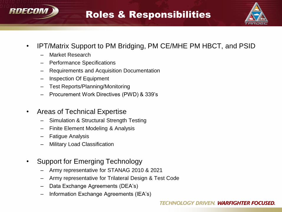
Roles & Responsibilities
• IPT/Matrix Support to PM Bridging, PM CE/MHE PM HBCT, and PSID
– Market Research
– Performance Specifications
– Requirements and Acquisition Documentation
– Inspection Of Equipment
– Test Reports/Planning/Monitoring
– Procurement Work Directives (PWD) & 339’s
• Areas of Technical Expertise
– Simulation & Structural Strength Testing
– Finite Element Modeling & Analysis
– Fatigue Analysis
– Military Load Classification
• Support for Emerging Technology
– Army representative for STANAG 2010 & 2021
– Army representative for Trilateral Design & Test Code
– Data Exchange Agreements (DEA’s)
– Information Exchange Agreements (IEA’s)

US Army Materiel Command
(USAMC)
US Army Tank-
Automotive and
Armaments Command
(USA TACOM)
US Army Research,
Development and
Engineer Command
(USA RDECOM)
Tank Automotive RDEC
(TARDEC)
Product Development Business Group
(PDBG)
Force Projection Technology
(FPT)
Combat
Engineering
Team
Logistics Equipment
Group
AFSC, JMC, AMCOM,
CECOM, CMA,
USASAC, PM SANG
Bridging Team
Engineering Business Group
(EBG)
Research Business Group
(RBG)
AMSAA, ARL, ARDEC, CERDEC,
ECBCNSC, S&TTC, RDECOM Acq C
Maneuver Support
Equipment Assured Mobility
Systems


Multi-Role Bridging Company
• The Multi-Role Bridge Company Equipment:
– Common Bridge Transporter, Improved Boat Cradle & Bridge Adapter,
Pallet, M1077 Pallet, Palletized Load System Trailer, Dry Support Bridge,
Improved Ribbon Bridge/Standard Ribbon Bridge, Bridge Erection Boat
– Objective is 23 full companies and one training company
Standard Ribbon Bridge bays in Raft configuration
Bridge Erection Boats provide raft propulsion
Standard Ribbon Bridge bays in Bridge configuration
Bridge Erection Boats provide temporary anchorage
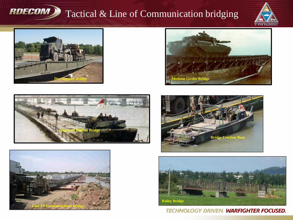
Tactical & Line of Communication bridging
Dry Support Bridge
Bailey Bridge
Line Of Communication Bridge
Bridge Erection Boat
Improved Ribbon Bridge
Medium Girder Bridge
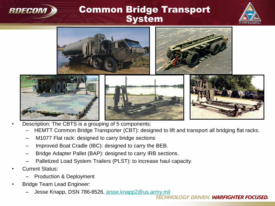
Common Bridge Transport
System
• Description: The CBTS is a grouping of 5 components:
– HEMTT Common Bridge Transporter (CBT): designed to lift and transport all bridging flat racks.
– M1077 Flat rack: designed to carry bridge sections
– Improved Boat Cradle (IBC): designed to carry the BEB.
– Bridge Adapter Pallet (BAP): designed to carry IRB sections.
– Palletized Load System Trailers (PLST): to increase haul capacity.
• Current Status:
– Production & Deployment
• Bridge Team Lead Engineer:
– Jesse Knapp, DSN 786-8526, [email protected]

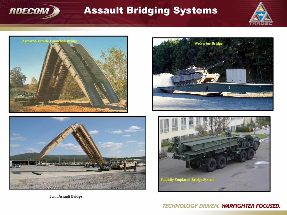
Armored Vehicle Launched Bridge
Joint Assault Bridge
Wolverine Bridge
Rapidly Emplaced Bridge System
Assault Bridging Systems

Assault Breacher Vehicle
• Description:
– Full tracked combat engineer vehicle for the MAGTF & Army HBCT to breach minefields
& complex obstacles and provide in-stride breaching capability to maneuver forces.
• Specs:
– M1A1 Abrams tank hull
– 2 Mk 155 Linear Demolition Charge systems
– Interchangeable Full Width Mine Plow & Combat Dozer Blade
– 2 lane marking systems
• Manufacturer:
– JAB designed in-house by Marine Corps Systems Command (MCSC)
– Anniston Army Depot (ANAD) is production site
• Current Status:
– USMC Lead with the Army as a participating DoD component as established in a signed Memorandum of Agreement.
– First Army delivery planned 2QFY09
• Bridge Team Lead Engineer:
– Percy Kirklin, DSN 786-7397, [email protected]


• Composite Army Bridge (CAB)
• Modular Composite Bridge (MCB)
Critical Design Parameters• Maximum Span: 25 meters
• Width: 4.0 meters
• Rating: MLC 65 (Tracked & Wheeled)
• Minimum Life: 5,000 crossings
• Results: 1,000 DLL Fatigue Cycles
Fracture at 166% DLL
Critical Design Parameters• Maximum Span: 12 meters
• Width: 4.01 meters
• Rating: MLC 100 (Tracked & Wheeled)
• Weight: < 6,000 kg
• Minimum Life: 5,000 crossings
• Results: 2000+ MLC70/100 in Field
18K MLC70 Simulation Cycles
Completed Technology Demonstrations
R&D Composite Efforts

LOADED HET & M1 CROSSINGS:
Composite Army Bridge

100
150
200
250
300
350
10,000 10,500 11,000 11,500 12,000 12,500 13,000 13,500 14,000
Weight (lbs)
Cost ($
1,0
00)
Comparable Aluminum
Bridge
(Baseline-MLC 70)
High Cost/
Low Weight
Low Cost/
High Weight
Prototype MLC 70
Design
Prototype MLC
100 Design
MLC 100
Production 100
Units
TRADEOFF METRICS:
Composite Army Bridge

Test Load Summary Treadway #1
(kips)
Working Load 4/26/99 Moment 170.15
Shear 150.12
Shear 151.19
Overload 4/27/99 Moment 228.67
(1.33 x W.L.) Shear 198.83
Cyclic 5/3/99 Moment 170.93
(W.L. x 1000) 151.18
5/4/99 Shear 152.08
Calc. Ultimate Load 5/4/99 Moment 258.62
(1.5 x W.L.) Shear 223.61
Design Load 5/499 Moment 309.24
(1.8 x W.L.)
Failure Load 5/4/99 Moment 375.63
(2.2 x W.L.)
Test DateLoad
Type
Total Load
STRUCTURAL STRENGTH TESTS:
Composite Army Bridge
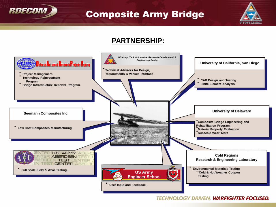
• CAB Design and Testing.• Finite Element Analysis.
•Composite Bridge Engineering and
Rehabilitation Program.•Material Property Evaluation.•Subscale Wear Tests
US Army, Tank Automotive Research Development &
Engineering Center
• Technical Advisors for Design,
Requirements & Vehicle Interface• Project Management.• Technology Reinvestment
Program.• Bridge Infrastructure Renewal Program.
• Low Cost Composites Manufacturing.
• Environmental Materials Testing–Cold & Hot Weather Coupon
Testing
• Full Scale Field & Wear Testing.
• User Input and Feedback.
PARTNERSHIP:
Composite Army Bridge
University of California, San Diego
University of Delaware
Cold Regions
Research & Engineering Laboratory
Seemann Composites Inc.

Gap 16 mGap 10 m
Advanced Modular Composite Bridge (AMCB)
To demonstrate leap-ahead advancements in light-weight modular bridging, utilizing composite
materials, in support of the next generation of gap crossing solutions for the Army’s Future Force.
Gap 26 m
Gap 22 m
Performance Requirements MLC 45*/70 (Threshold/Objective)
13m/26m Gap (Threshold/Objective)
3.35m/4.0m Deployed Width (Threshold/Objective)
C-130 Transportable/ Roll-On Roll-Off Capable (Threshold/Objective)
23,000/19,000lb Bridge Weight (Threshold/Objective) for a 26 meter Gap
6m Bridge Rack/Pallet Maximum Length Objective
4m Overpass Clearance on FTTS or PLST
Interchangeable Modules; supporting a “Family of Bridges” approach
Pre-Pinned/Auto-Mating Joints (Threshold/Objective)
CH47 Helicopter Transportable in 13m/26m (Threshold/Objective) Configuration
R&D Composite Efforts

Ultimate Failure Testing of Advanced modular Composite Bridge (AMCB) at UCSD
3 Section all Composite Treadway
Design Load MLC 45 Threshold/70 Objective
Ramp to Center Panel Connection
Internal view of
Treadway without
Deck
View of
CompleteTreadway
Before ultimate failure
test at UCSD
R&D Composite Efforts

Ultimate Failure Testing of Advanced modular Composite Bridge (AMCB) at UCSD
3 Section all Composite Treadway
Design Load is MLC 45 Threshold/70 Objective
Failure Load 3.2 times Design Load
357kips of Total Vertical Load
Failure occurred in the Ramp to Center Panel Tension Joint as intended.
R&D Composite Efforts

GAP DEFEAT TECHNOLOGY – Composite Decks (Treadways)
Salient Features•MLC 30T/65W
•Deck:
Length 5 m (16’ 6”)
Width 0.76 m (30”)
Depth 0.1 m (4”)
•Weight 345 Kgs. (760 lbs)
• Polymer Composite:
- Fiberglass
- Graphite
- Epoxy
- SCRIMP
•Polyurethane Wear Surface
•Proof Tested to 1.33 working Load
Composite Treadways
M113 Crossing Turretless M60 Crossing
HMMWV Crossing
CBT Crossing
Discussions with
Treadways Designer
R&D Composite Efforts
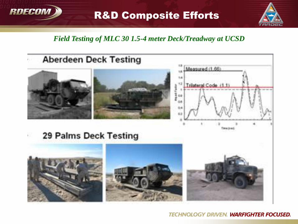
Field Testing of MLC 30 1.5-4 meter Deck/Treadway at UCSD
R&D Composite Efforts

Research & Development
Efforts
• Title: Rapidly deployable gap defeat technology
(GDT) for the Future Combat System (FCS) /
Future Force (FF)
– Description: Provide a 1.5 to 4m wet/dry gap bridging
technology that is MLC 30/70 (threshold/objective)
capable, C-130 aircraft transportable, weigh less than
3000 lbs., can be remotely operated or autonomous, and
can be integrated with future FCS vehicle platforms.
– Funding Type: Broad Agency Announcement (cost
sharing contract: 60% govt, 40% contractor), Phase I
• Title: Innovative Wet Gap Crossing
Technologies for the Future Combat
System/Future Force
– Description: Develop an infinite wet gap spanning bridge
technology that is C-130 transportable, MLC 30/65
(threshold/objective) capable, and able to be integrated
with the Future Combat System vehicles.
– Funding Type: SBIR (cost + fixed fee contract), Phase II

Research & Development
Efforts
• Title: Assured Operational Mobility Across
Gaps for the (FCS/FF)
– Description: A flip cantilever bridge and launch
technology to remotely deploy a bridge and keep the
soldier out of harms way
– Funding Type: SBIR Phase II
• Title: Gap Defeat Technology for the FCS
– Description: Sense the gap, Remotely Inflatable
Fascines to be dropped in the 1.5 – 4 meter gaps; C-
130 transportable, CH47 deployable
– Funding Type: 6.2

Research & Development
Efforts
• Title: Repair and Health Monitoring of Composite Military Bridges
– Description: Diagnostic/Prognostic Structural Health Monitoring of Composite
Bridges and their repair, Field/Depot Repair Methodologies
– Funding Type: SBIR
Depots/TACOM
Satellite
Bridge Launcher Control Panel
SRK Repair Patch
Warning & Verification – Go/No Go
System for On-coming
Vehicles


Light Assault Gap Crossing
(LAGC)
LAGC Family of Bridges
– Short gap crossing capabilities gaps will be identified in the upcoming LAGC Capabilities Development Document (CDD). This CDD will breakdown the capabilities into three separate categories:
• Tier 1: Dismounted - Footbridge:
– Soldiers on dismounted patrols are often required to cross canals. Soldiers currently have no means for safely crossing the canals short of wading across, and have requested canal crossing equipment that is Soldier-portable, easily and quickly emplaced, and recoverable after crossing to carry to the next canal to be crossed.
• Hand emplaced
• Fixed- length from 1 to 25 m
– Capable of sustaining one soldier crossing at a time, approx 280 lbs ea
• Floating- length up to 50 m, current velocity less than 6 fps
– Capable of sustaining multiple soldier crossing at a time (5 m intervals), approx 280 lbs ea
• Tier 2: Mounted – Short Gap:
• 4-8 m length
• HUMVEE type of launch platform - light maneuverable launch/retrieve platform
• MLC 45
• Launch time: < 5 minutes
• Tier 3: Mounted - Medium Gap:
• 13-18 m length
• Platform: Bradley or Stryker type of platform
• MLC 45
• Launch time: < 5 minutes while crew is protected in platform while under fire

Multi Functional Gap Defeat
Assault
Tactical
Assemble into MLC-100 T&W Concepts:
26-meter Assault
48-meter Tactical 26-meter
48-meter
Develop a prospective, single solution for Assault, Tactical and Line-of-
Communication gap defeat that communicates in real-time its usage
and safe load carrying classification.

Composite Joint Assault Bridge
Requirements:– MLC-100 Load Class at 18m (threshold), MLC-100 at full span (objective)
– span 24 Meters
– interface with JAB vehicle
– deploy/retrieve within 3 minutes (objective)
– allow for traffic of tracked and wheeled military vehicles
Leverage technology and lessons
learned from UCSD Advanced Modular
Composite Bridge
Joint Program: Army, Marine Corps, and Navy
Development of 6.3 funded technology
demonstration full scale composite JAB