BRIDGE FATIGUE GUIDE - AISC Home · BRIDGE FATIGUE GUIDE DESIGN AND DETAilS by Dr. John W. Fisher...
65
BRIDGE FATIGUE GUIDE DESIGN AND DETAILS AMERICAN INSTITUTE OF STEEL CONSTRUCTION
Transcript of BRIDGE FATIGUE GUIDE - AISC Home · BRIDGE FATIGUE GUIDE DESIGN AND DETAilS by Dr. John W. Fisher...
BRIDGE FATIGUE GUIDE DESIGN AND DETAILS
AMERICAN INSTITUTE OF STEEL CONSTRUCTION

BRIDGE FATIGUE GUIDE DESIGN AND DETAilS
by
Dr. John W. Fisher
Professor of Civil Engineering
Fritz Engineering Laboratory
Lehigh University
Bethlehem, Pennsylvania
AMERICAN INSTITUTE OF STEEL CONSTRUCTION 400 North Michigan Avenue, Olicago, IL 60611
AISC Committee on Bridges
A. C. Van Tassd, Chamnan Plitsburgh-Des MOines Steel Co. Lawrenet . BIgelow Amencan Bridge DWlSlon, u.s. Steel CorporatIOn. Donald C. Frederickson (AdvISory) Bethlehem Steel Corp. Wesley A. King K 6- S Englneenng Co. J ohn F. W. Koch InternatIOnal Steel Compony Andrew Lally Amencan Inslltute oj Steel ConstructIon William A. Milek Amencan In slltute oj Steel ConstructIOn Werner Quasebarth Alias Machllle 6- Iron Works, In c. Brock C. Rowley Bmtol Steel 6- Iron Works, In c. John L. Sally Peden Steel Company Robert S. Sherman Carolina Steel CorporatIOn Raymond H. R. Tide Amencan Inslltute oj Steel Construcllon F. Ayers Williamson Amencan In slltute oj Steel ConstructIOn
AREA Advisors
John E. Barrett Alfred Benesch 6- Compony, Consulting Engineers John W. Hartmann Burlington Northern, In c.
AASHTO Advisors
Charles PcslOtnik Iowa Department oj TransportatIOn Frank D. Sears Federal I hghway Admlntstrallon Carl E. Thunman, Jr. illinois Department oj TransportatIOn
Associate Advisor
Hugh Krentz Canadzan InstItute of Steel Construct ron
Copyright © 1977 by Amencan Inslltute oj Steel Construction, In c. All nghts reserved. No port oj thIS publICation may be reproduced WIthout WrItten penntSSlon.
The material presented in this publication has been prepared in acoordanet with recognized engineering principles and practices and is for general information only. The reader is cautioned that independent professional judgment must be exercised at all times when the data or recommendations SCI forth in this publication are considered and / or applied. The publication of the material contained herein is not intended as a rtpresenlation or warranty on the part of the American Institute of Steel Construction-or of any other person named herein-that this infonnation is suitable for any general or particular use, or of freedom from infringement of any patent or patents. Anyone making USe of this information assumes all liability arising from such use. The material contained herein is not set forth for purposes of design, but as a guide only. The design of structures is with," the scope of expertise of a competent licensed architect, structural engineer, or other licensed professional for the ap~ plication of principles to a particular structure.

PREFACE
It is estimated that the.- a.- mo.- than one-half million steel highway and railroad brid~es in the United States. With only a few exctptions, these structures have performed ","isf.tnonly in e .... ery respect and, in mosl cases, have c.:1rrird loads far in excess of those for which they were designed .
During the past decade, a great deal of research has been focused on the effects of the repetitive loadings to which highway and railroad bridges are subjected This work, a well as lessons learned from the reiatively few cases of undesirable performance, have led to a bettor understanding of bridge fatigue behavior and to substantial changes in fatigue proYlsion of bridge design specifications.
This booklet has been prepared as a gu.de to the general problem of bridge falJ~ue and to a is! the designer with the selection and design of bridge details that offer superior falJ~ue strength. It is a revised and expanded ver ion of theearlier AI C booklet GUIde to th.' 1'174 AA liTO Fallgue SpecificatIOns.
ince 1974, ponions of the AA HTO fatigue specifications have been adopted by AREA and AI C. Hence the classification of various details and their permissible stress ran~e for spec.fied load cycles is now identical for all three specifications. As a resuit, the general application of the AA HTO fatigue provisions to the design examples for highway bndges are equally applicable to other structu.-s. Olmously, the loading conditions and desi~n life critoria will differ, depending on the application.
A method for estimating equivalent design life for use with constant cycle fatigue stresses is described for highway bridges. This permits the potential cumulative damage of random truck traffic to be accounted for in design A romparable approa<h for railroad brld~e can also be found in the Commentary to the AREA Specification, reproductd in AppendIX B
One of the majOr fatigue problems that has surfaced in .-cent years i crackin~ from e('ondary and displactment-inductd stresses. D.scussed brieny in the 1974 Guide, thIS ubJC<1 IS treated In much greater depth in Chapter 5 of thIS booklet. The problem has de.e1oped because many bridges are essentially linear structures and are designed for in-plane loading and deneaion of the main girders and the cross·framing. However, even though intr-raC'tlon bf:tween the longitudinal and transve~ framing does not alter the in-plane behavior of th~ framing enough to economically justify a spact frame analysis, it is of p.1ramount .mpon.nct to cons.dor the distonions resulting from such intoraction. Genoraliy, tht effects of secondary and displacement-induced stresses are seen at conneCtions to main members. The ~ .... r-rit)· is often dependent on geometrical conditions which the designer can control. These are discussrd at length and recommendations provided as to how the problem may be minimized or avoidtd. A general procedure for the design of connections to insure the intendtd performanct is provided at the end of Chapter 5.
The direct applicability of fatigue specifications to the main load carrying member has usuall} been "C)' appartnt to bridge drsi~nors. As a result , appropriatO details ha\e ~en prO\:idr<! which satisfy the specification requirements. Howe .... er. the design of SttOndary members and conntttions has not always bttn as obvious. Often thest members interi.Kt with the mam members and receive more numerous cycles of stress with a higher stress rang~ th~ln assumr<!. Discussion of this problem is provided and recommendations given on the treatment of such components.
A brief discussion of the background and history of fatigut spe ifications for h.~h\Vay bridge. is provided, as wtll as a summary of tht laboratory studies on fatigue that form the rationale for the stress range concept and lead lO the current specification provisions.
Aniele 1.7.2 of the 1977 AASHTO Specifications, and Art. 1.3.13 of the 1977 AREA pecifications and its Commentary, are reprodll~d in full in Appendix B They contain the
111

major changes to Art. 1.7.3 of the 1973 AASIITO p<cifications and Art . 1.3. 13 of the 1976 AREA p<eifications. These changes ar< summarized at the beginning of App<:ndix B.
The causes of fatigue problems and a number of examples are examined in detail in thIS booklet. The recommendations provided throughout are intended to aid in minimizing and avoiding these problems in the future. The ustr is urged to examine in detail the various sections of this booklet throughout the design of a cyclically loaded Structure.
This book let was sponsored by the American Institute of Steel onstruction under the auspices of the AISC Commillee on Bndges. The author is indebted to the Commillee and liS Advisors for their many suggestions and adviee. The AISC Commillee also provided the design exam ples contained herein.
Acknowledgment is also due those organizations who sponsored research at Fritz Engi. neering Laboratory, Lehigh University, into the fatigue behavior of welded steel details. Much of the research provided background and eXp<:rientt for the preparation of this booklet. Those sponsoring research work include the Pennsylvania Department of Transportation ,
alional Cooperative Il ighway Restarrh Program- Transportation Research Board, National Academy of Sciences, and the Un lied States Department of Transportation Federal Highway Administration.
The author would like to acknowledge his colleagues and Research Assistants who have worked with him on various research projects: P A. Albrecht, K. D. Boyer, A. Coates, J II. Daniels, D. A Erb, K. II. Frank , W. C. Ilerbein, M . A. Hirt , G . J. Inukai , G . R. Irwin , R. Jaccard, D. J. Klingerman, N. V. Marchica, B M . )'IcNamee, A. W Pense, R. Robert., R. E. lock bower, f I. Woodward, B. T Yen, and N. Zwlemoyer. Also, H T . utherland, Instruments ASSOCIate, and the laboratory support staff under the sup<:rvision of K. Il arp<:l , R. R. Dales, K. Eberts, and R. Hillinger, provided invaluable assistanee throughout the laboratory and lield investigations.
Thanks are also due Ruth G rimes for her assistanee with the preparation of the manuscript and to R. Sopko for the photographic coverage.
May, 1977 J ohn W. Fisher
I.

CONTENTS
Preface ................................ . .. .. . . . , .... . .....•... , ....... . • . .. .. . .. . III
Chaptc:r 1.
Chapter 2.
Chapter 3.
Chapter t
Design Details to Optimize Fati~ue Strength . . .. .. . • • ... . • •. ...• •.. . . • •.. . •
Design Examples ........... .. .. .. .. . ................ • .....•.....•..... 7
Stress Cycles for Design ......••....•.... . •. . .. .• . .. .• • .... . • ..........• 1.
Stress Range Concept ........••• . . . •.....• .. ..••• . ..••• • ....•....•• • ... 17 Innial Discontinuilles 17 Fatigue Strength 17 Residual Stressts 19 Variable Stress Cycles 19 Curr!.":nl Research '20
Chapter 5. Connections-Fatigue Considerations as a Result of Secondary Slrcs!>c!> .•. •. .• 21 Restraint al Simple: End Connections 21
Problems with Dislorllon of Simple End Conntcl lOn Components Problems with Restraint Summary and Recommendations for Simple Connections Subjertcd
10 CyclicaJ Loads Displacements at Stringer Connections and Web Brarkets!25
Flange Twisting and lor Lateral Movement Recommendations to Minimitt the Effects of Out·of·Plane Movement
at Stringer Connect ions Out·of·Plane Displacements at Floor Beam Connect ion Platts and
Trans\lerse St iffeners ,'28 End Rota tion of Floor Beams Trans ... erse Slifftntrs Summary and Recommendations for Floor Beam Conntctlon Plates
and Transverse Stiffeners Suggested General Procedure for Design of Connections,' 3 !
Chapter 6. Secondary MembeTS and Connections ........... . ........ . .. .... ........ . 32 Displacements at Diaphragms and Cross· Frames '32 Summary and Recommendations for Diaphragms and Cross· Frames 3" Lateral Bracing and Lateral Gusset Plates/ 34
Out-of-Plane Movement at Late ra l Gusset Plates Stresses in Lateral Gusset Plates Vibration of Late ral BraCing
Recommended Details at Lateral Gusset Plates/ 37
Chapter 7. Miscellaneous Fatigue Considerations . ... . . . ... . .. . ...................... 39 Displacement Induced Secondary Stresses in Other Structural Systems 39
Out-or-Plane Bending in Connection Plates of Cantilever Floor Beam Brack('ts Recommended Details for Cantilever Bracket Connection Plates Secondary Bending Stresses in Truss J oints
kewed Bridges/ 41 Onhotropic Sted Decks/ 42 Weld Requirements and Special Considerat ions 43
Groove Welded Spli= Transition Radii
Appendix A. References ................ . ... .. . .. . ..........• • •..••••...•.... ... . . 4S
Appendix B. AASHTO and AREA Fatigue Specifications .. ..... ...................... 47 AASHTO Article 1.7.2/ 47
AREA Articles 1.3.13, 2.3.1 and Commentary Articles 9.1.3.13 and 9.2.11 ' 52
v

Design Details 1
CHAPTER 1
DESIGN DETAILS TO OPTIMIZE FATIGUE STRENGTH
The major factors governing fatigue strength are the applied stress range, the number of cycles, and the type of detail.
(ruttural details behave differently because the stress con· ~nlration condition changes. The inherent variability of initial discontinuities is also a major factor.
All welding processes introduce small discontinuities in or near the weldment. Although good welding practice will minimize the number and size of these discontinuities, they cannot be eliminated. The fatigue design rules were developed from research on test specimens that contained normal disronlinuities. The usual visual inspection of fillet welds and longitudinal groove welds and the nondestructive inspection of transverse groove welds in tension nanges may detect discontinuities that are adequately accounted for in the design provisions for fatigue. In fact most attempts to remove al· lowable discontinuities from manufacturing and fabrication that are permitted by ASTM and A WS will result in a condition that is worse than the original condition.
For design there are two options available: (I) the choi e of a detail (or the severity of the stress concentration introduced by a detail) and (2) limiting the stress range to acceptable levels.
Details that provide the lowest allowable stress range in· vo}o.;e connections that experience fatigue crack growth from weld toes and weld ends where there is a high stress concentration . This is true of both fillet and groove welded details . Dctails which serve the intended function and provide the highest fatigue strength should be considered.
As a general rule, details which involve failure: from internal discontinuities. such as porosity, slag inclusion, cold laps, and other com!,,1rable conditions, will have a high allowable stress ran~e. This is primarily due to the fact that there is no geometrical stress concentration at such discontinuities other than the effect of the discontinuity itself.
The AA HTO Specifications, in Table 1.7.2A2 (see Appendix B), describe \'arious situations and categories. imilar prOVISions are provided by AREA in Table 1.3.13C (see . \ ppendix B). A more detailed evaluation of typical welded bridge details for fati~ue loading is given in Ref. I.
The stress cycles for faligue design stresses are defined by the bridge location and type of member (see Table 1.7.2B). The maximum stress ranges permitted on the bridge for the various stress cycles are listed in Table 1.7.2A l of the
AAS HTO Specifications. Tables 1.3.13A and B provide this information in the AREA pecifications. If well defined traffic conditions are known, lhese should Ix used in lieu of the Slress cycles in Table 1.7.2B or in Table 1.3.13B to determine a suitable design life and the corresponding allowable stress ranges; the use of an equivalent design life tS discussed in Chapter 1
Thus, the designer can, to a large extent, control the type of detail selerted and its location in regions of significant cyclic stress. Every attempt should be made to place Category E details in regions of low cyclic stress, so that the member size need not be increased. For example, coverplated beams can have the cover plate termination extended into regions of low stress range.
A wide class of fi llet and groove welded details is covered by Category E.' Ilowever, alternate details which result in higher allowable stress ranges are available and can be used.
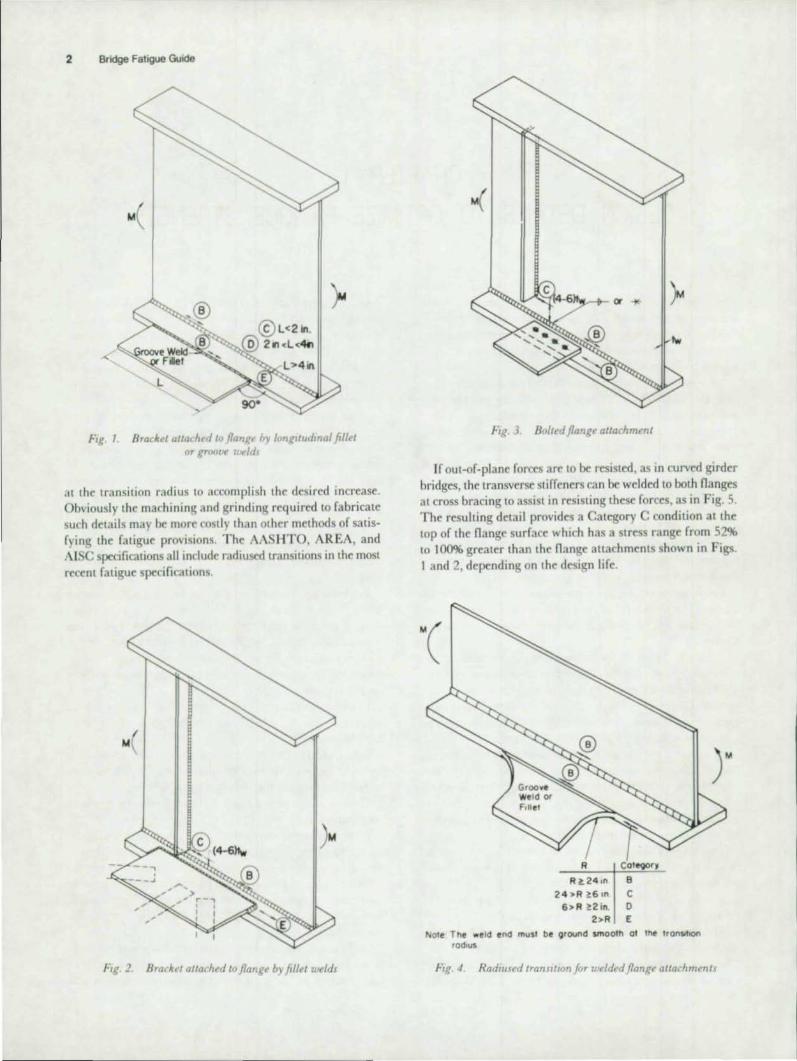
For example, transverse or lateral bracing which frames into a girder, as illustrated in Figs. I and 2, results in a Cat· egory E detail on the nange surface at the weld end . If the stress range is critical, details such as shown in Figs 3 and 4 will provide much higher allowable stress ranges. Also, as shown in Fig. 5, the detail could be moved to a location where the stress range is smaller.
In many structures it may be possible to omit the lateral bracing system in the high stress range regions of the span. Lateral bracing is not required in highway spans up to 125 ft long (AAS IlTO) or in railroad deck spans up to 50 ft (AREA). In longer s!,,1ns, a continuous lateral system may not be required over the full length of the structure.
For a more complete discussion of lateral ronnmion details, see Chapter 6.
If the attachment were bolted to the nange as in Fig. 3, the allowable stress range: is increased to Category B on the net section for a bearin~-type connection and the gross section for a friction-type connection. This permits a higher allowable stress range than for the welded attachments of Figs. I and 2 . The reduction in net area will only slightly reduce this in· creased ratigue strength .
Still another method of increasing the allowable stress range is to use attachments with a "radiused" transition, as illustrated in Fig. 4. The weld ends must also be ground smooth
2 Bridge Fatigue Goode
Fig. I. Brackd atlachf'd ltJ flanl!f' h\ Innglludmal fill~l or gmfJl~ u't"ld.
at the transition radius 10 accomplish the desired increase. Obviously the machining and grinding required to fabricate such delails may be rnor cOSIly Ihan olher mel hods of salisfying Ihe faligue provisions. The AAS IITO, AREA, and AlSC specifications all include radiused transitions in the most reeent fatigue specifications.
fig. 2. Braclul alloc"hed /() f1ang~ by fillet welds
FIg. J. Bo/lt'd flange attachment
If oUl-of-plane forces are 10 be resiSled , as in curv,d girder bridges, Ihe Iransverse Sliffeners can be welded 10 holh nanges at cross bracing to assist in resisting Lhese forces, as in Fig. 5. The resulling delail provides a Calegory C condilion al Ihe lOp of Ihe nange surface which has a Slress range from S2% to 100% greater than the nange 3n3chmenls shown in Figs. I and 2, depending on Ihe design life.
R Cote9C)fY
R ~ 241" B 2 4 ,.R ~6,n C 6>R~2in. 0
2>R E
NOle The weld end musl be oround smooth of ttw tranSItIOn radiUS
f ig. 4 R adtused I ranjltwn for uoelded f/angtO altachmen/j

2
I ~4-6h" P E'
It is Important to rra lize that any detail ca n be used if it is properl y acrounted for in the design. The simplest detail consisten t with the stress requ irements wi ll generally be the mOSt desirable from the standpoint of design, fahri alion, and economy.
W hen tran"e"" and longitudinal stiffeners are used, ea(h providn a weld termination, as is illustrated in Fig. 6. in~
lranH 't'rlt' and /orlgllutimaililjjeners
Design Detail. 3
F,g. 7. TronSt't'ru' and f,mgllu,Jlnal J/llf~n,.,.s plat I'd on f'l,pOIl/t' utlt') nJuxb
the longitudina l stiffener i, a I()n~ attachment, the end of the stiffener is governed by the Category E desi~n condition At other points along the stiffener, Category B is applitable The transverse stiffener docs nOt provide as ~\lere a condition, bttaust it is much lihonrr in thr dlrcftion of applard Slrf",.,. If both types of stiffene", are needed III an drea of Sire', r"eKlI, the most desirable fondltinn (~'" Ix- athlt'\ed b\ plann~ the longitudinal stiITener on one 'Ide (If thr web and the tran~\erY stiffener on the other, '" In h~ 7, '" that the lon~"udlnal wdd can be contlnuou\ and thr longitudinal 'lirfener can either be terminated In a r("~lOn of low stress ran~r or ('()Ill
pressivc stress, or inrorporate a radiused transition .11 Its end
Fillet welds for tranwrfse stiffeners should lx termlnatcd
short of the web-IO-n",~e weld, by a diSlanre of at 1 • .1" four 1 and up to six timc\ tht' web thirkness. as illustrated in Figs. 2,3,5,6, and 7, and ,hould not he returned around the end, of the stiffener. Failure 10 !rrminme stiffener wtld\ a suitable distan~ above the wt'f>..n;IIl~(, foon('(llOO tan r~ult In adv('r;t' behavior. due to reslrainl 'ilresses Inlroducrd by weld shrinkage and possibk rydll" stresses due to transvrrt;(' movements durin~ c;hlJ)plO~ or hJndlin~. Thi is di'it"us...ro In
grealer detail later. in lht" c.;('( lion dealin~ with 'i('{oodar, Slresses (Chapter 5).
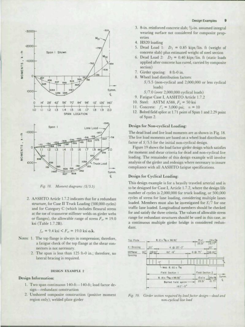
Transverse groove wrlds in rt1(ion ... of ndir ttnCaon or ~LI"f"'; .... reversal are examined by Ilonde'itrufti"e insiXuion , .. 15 'iJXf· iritd on plans or joh Slxc:irifatlon'i, to inc;urt th~H rK(eS\IV(' internal dio;;continuitirc; art not prtsent. Improvements in fa· ligue strength can I~ afhleH"cI by removal of tht wrld rem· forcemem and by appropriiltt transition,,; brtween plates uf different thickness or width . a,,; illustrated in Fi~s . R ilnd 9
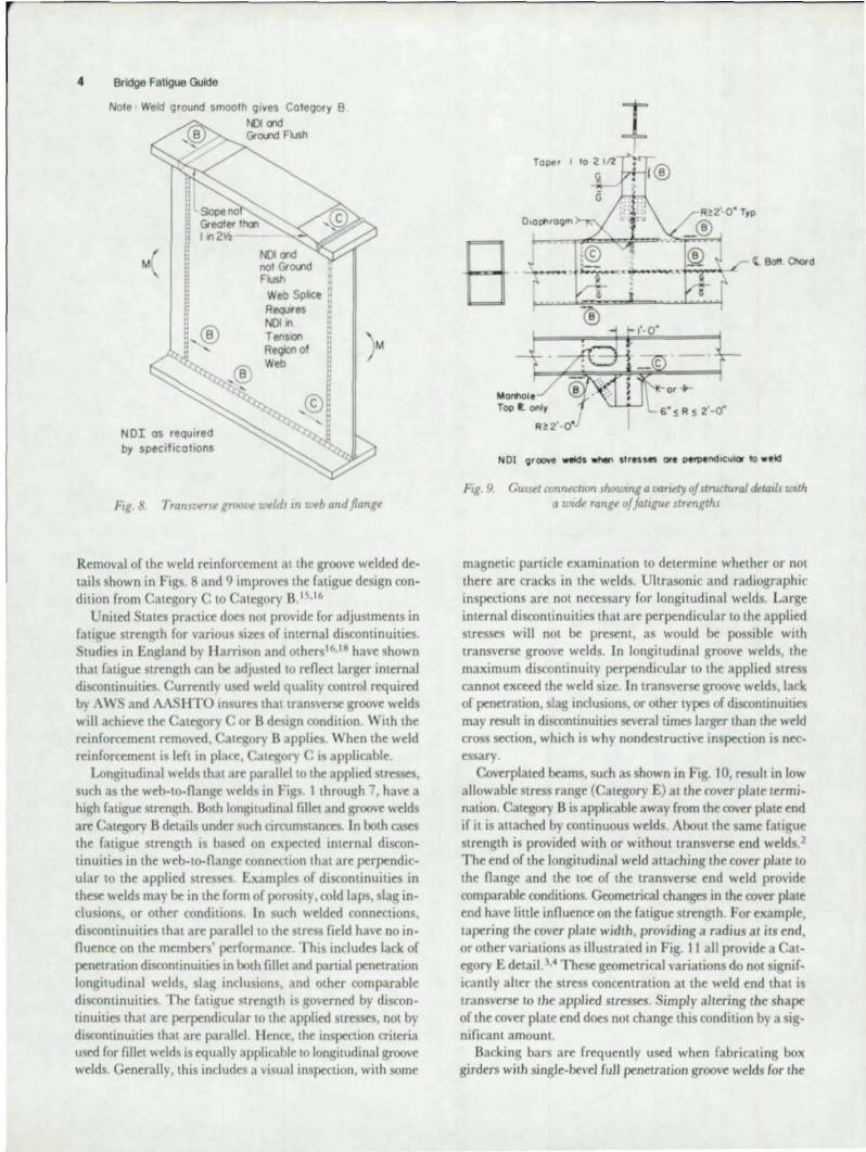
4 Bridge Fatigue Guide
Note Weld ground smoofh gIves Category B
i'lJI mel Gl'a...nd Flush
M
Slope no Gl'eoter tim t,"2~
N or as required by specifications
Web Sptoce ReQ,Wes NDI " Tension RegIOn of Web
Fig. 8. Transvvu groow weldl In UNb and flange
Removal of the weld reinforcement at the groove welded details shown in Figs. 8 and 9 improves 'he fa'igue design condi,ion from Category C '0 ategory B.",16
Unit~d tales practice d~s not provide for adjustments in fatigue strength for various sizes of internal discontinuities. Studies in England by Il amson and OIhers '6,18 have shown ,ha, fatigue streng,h can be adjusted to reflee, larger internal discontinuities. Currentlv used weld quality control required by A Wand A1\ I ITO tnsures that transve~ groove welds will achie,e 'he Category C or B design condi,ion. With the reinforcement removed, alegory B applies. When the weld reinforcement is left in place, ategory is applicabl~.
Longitudinal welds that are parallel '0 'he applied stresses, such as 'he web-,o-flange welds in Figs. I ,hrough 7, have a high fa'igue strength. Both longitudinal fille, and groove welds are Ca'egory B details under such circumstances. In both cases 'he fatigue strength is based on expected in,ernal discontinuities in the web-lO-nangc connection that are perpendicular to the applied Stresses. Examples of discontinuities in these welds may be in 'he form of porosity, cold laps, slag inclusions, or other conditions. In such we:lded connections, discontinuities that are parallel to the stress field have no in· fluenee on 'he members' performan,e. This includes lack of penetration discontinuities in both fillet and panial penetration longi,udinal welds, slag inclusions, and other comparable discontinui,ies. The fatigue strenglh is governed by discon,inuities ,ha, are perpendicular '0 the applied stresses, no, by discominuities that are: parallel. 1Ienet, the inspection criteria used for fillel welds is equally applicable to longiludinal groove welds. Generally, this includes a visua l inspection, with some
Tope' I
Manhol e Top e. only
R!:2' · O·
NOI 9rOCl'ft welds ...... st,.ss," or. p.",.nchcukw to •• Id
FIg. 9, Gusset amn«tlon shOWIng a uanety of structural tkulIls Ultth a wlde range of faLlgue strengths
magnetic particle examination to determine whether or not ,here are cracks in 'he welds. Ultrasonic and radiographic inspections are not necessary for longitudinal welds. Large internal discontinuities that are perpendicular to the applied stresses will nOl be present, as would be possible with transverse groove welds. In longitudinal groove welds, 'he maximum discontinuity perpendicular to 'he applied stress cannot ex~ed the weld size. In transverse groove wdds, lack of penetration, slag inclusions, or orner types of discontinuities may result in di .. continuitjes several times larger than tht weld cross section, which is why nondestructive inspection is nec .. essary.
Coverplated beams, such as shown in Fig. 10, result in low a llowable slress range (Ca,egory £) at the cover plate ,erminauon. Category B is applicable away from the cover plate end if it is allached by continuous welds. About 'he same fatigue strength is provided with or without transverse end welds.2
The end of 'he longiludinal weld allaching 'he cover plate '0 the fl ange and the toe of the tranSverse end weld provide oomparable conditions. Geome,rical changes in the cover pla'e end have lillie innuence on the fatigue strength. For example, tapering the rover plate width, providing a radius at irs end, or o,her variations as illustra,ed in Fig. 1 I all provide a Ca,egory E detaiL ' " These geometrical variations do no' significantly alter the stress concentration at the weld tnd that is transverse '0 the applied stresses. Simply altering 'he shape of the cover plate end does no' change this condition by a significant amount.
Backing bars are freq uently used when fab ricaling box girders wi,h single-bevel full penetra,ion groove welds for the

M
Cover Plate wrth 5q.Jae Ends
Fig. 10 Counplaled beam shoWIng regron of entleal fallgu~ sluss
web-to-nange connection. Care should be exercised with the use or such bars. Ir intermittent fillet welds are used to connect the backing bar to the web and nange plates, they may provide a Category E connection for the tension nange (see Fig. 12a). This con~rvati\'e t~tmenl or intermittent tack welds renects the lack of test data on this type of connection. Further research is being planned on thIS detail.
If backing bar> are needed, it is preferable for the connecting welds to bt- continuous on the tension nange, as illustrated in Fig. 12a, so that Category B is applicable. Alternately, intermittent wdds could be used and then removed arter completing the JOint. Intermittent welds can be used in rogions subjected to compression without any adverse effect on the member deSign Discontinuous backing bars should not be used.
gg 6"
'(J.'R (01 (bl (dl
, '. I I QQ .. I I I
~ ~r
. ". -'\--(el (I) (hI (Il
f-,~ . 11. End of COt'er plate details
/
eod< Up
Bar -...
I i (a) FuU PenelratlO(l We ld Wit" BaeklnQ Bor
I I
(bl Contmuous FlUet Welds
B
Ie) PortlOl Penetrollon Weld
Design Details 5
~ j I
The problems associated wi,h ha(kin~ bars can be aVOIded In some Instan~s. when girders ha\'t sufficiently thic:k web , by using either a paniaJ JXnetration groo\'e wdd or two fillet welds for the web-,o-nange connection (see Fi~. 12b and 12tl. Both of these joints prOVide a Cat<1!ory B connection Fillet welds may not be practicable for many boxes, bt-("au~e aeees may not penni' the placemen, of some of the IIlside fillet welds. A Single partial penetration groove weld can be provided without requiring a backing bar (see A WS Article 2.5 and 9. 12). It also permits easy access '0 'he box joints, . inte 'he welds can be made from outSide 'he boxes Both partIal penetration groove wdd and twin fillet wdd connections provide a Category B connection, which is the same fatigu(' strength de,ail as 'he full penetra,ion groove weld
Floor beam or cross-girder to longi,udlllal girder connections and stringer to rull.lenv;th tross·glrd('r COnnr(110n~ Jre a category of joints that can provid(' wide variation 10 fati~ue
strength Floor beams must either pa . 'hrou~h the lon~i'udinal gIrders or be attached to ,hem Typical example-, of noor beam.to-~irder connection are ,hown In Fig 13.md 14 . Among the problems of conttrn are th(' continuity or the noor beam nanges, 'he attachment of the noor beam nan~rs '" 'he girder nan~e, term Ina' ion of 'he web-,o-nange welds, and 'he aU3C'hment or pa sage or the noor beam ("ompre .. sion na",~e 'hrough 'he girder web .
If 'he noor beam ,ension nange IS passed over 'he girder, as illustrated in Fig. 13, wide variation in fatigue strength can result, depending upon how 'he noor beam web-,o-nange

6 Bridge Fatigue Guide
Web CleO! nol 51'1o .. n
NOl and Ground Flush
Floor Beam Of
Cross Girder
"'g. I J. Fhw,r beam-to-~lrder c01lnecilOn wllh continuoUS jlv)r beam flange
conneaion is treated. The groove weld in the fl oor beam flange is either Category B or C, depending on whether or not the reinforcement is removed or left intact. A more critical design condition is the terminal.on of the web-to-flange connection. I r these welds terminate, a Category E design condition results, as shown in Fig. 13. Sucil a large reduction in fatigue strength can be avoided by providing continuity in the web-to-nange weld, as shown in the in!-crl. A smooth radiuscd transition in the noor beam web can be provided at the CUIOut to accommodate the girder nangc.
If the noor beam compression nan~e is welded to the girder web as shown in Fig. 13, a Category £ detail results. This will penalize the fatigue strength if a hie;h tensile or reversal stress
Shop groove w. ld r--@ If IjIfOUnd f lush
0 r 0
• l • • 0
• • ~ • 0
0 0
• 0
Finish ends of flOnQe .. ..l B.II,d f ,.'d J 10 be or no flol'IQe we lds ,pllee In SInnOtt .
I
<
FIg. 1,/. Strl1lger-lo-jloor beam connectIOns wah hIgh allowable fatigue strength
range occurs in the girder web over a large number of cycles. A detail with a higher allowable Slress range will result if the noor beam nange is passed through a Cutout similar to that provided in the noor beam web.
A higher allowable stress range can be achieved in the longitudinal main member if the noor beams are bolted. This may be a more desirable design condition if relatively high Stress ranges are present. Figu re 14 shows two details that provide Category B design conditions at the stringer-noor beam intersections. In ooth ca s a Category C de ign condition would resulL in the noor beam from the web fillet welds or welded shear plate.
If the cyclic st resses in the girder web are not criticaJ and the detail shown in Fig. 13 is used ) care shou ld be exercised in the development of the nangc-to-wcb connection. If large noor beam nanges are groove welded to opposite sides of the web plates, shrinkage stresses will be introduced into the web plate which may result in restraint or lamellar Icars in the girder web.

Design Example. 7
CHAPTER 2 DESIGN EXAMPLES
Two design examples an: summarized to demonstrate:: the application of the AASHTO fatigue provisions. One is a simple structure designed by working stress design for stress cycle Case II; the second is a continuous structure proportioned by load faclOr design for stress cycle Case I.
DESIGN EXAMPLE I
Design lnformation:
I. 90-ft simple span; working stress design 2. Composite construction; rolled beam and cover plate 3. 8-in. reinforced concrete slab; Ih-in. assumed integral
wearing surface not considered for composite properties
4. HS20 loading 5. Dead Load I: [), = 0.85 kips/ lin. ft (weight of
concrete slab) plus estimated weight of Sled section 6. Dead Load 2: D, = 0.40 kips/ lin. ft (static loads
applied after concrete is cured, carried by composite section)
7. Girder spacing: 8 [[-0 in. 8. Wheel load distribution factor: S/ 5.5 9. Fatigue Case II , AASHTO Article 1.7.2
10. Steel: Fy = 50 ksi II. Concrete: f'< = 3,000 psi; n = 10
Moment Diagrams (Truck Loading):
See Fig. 15.
Select a Trial Section:
Try W36XI 70 with cover plate 10 in. x 1% in.:
Stress checks at point of maximum moment:
~lidsp3n
.\pplic- Fe fr fr able Concrete, Steel, Steel.
~Iomenl Top Top Bollom Load (kip-h) (ksi) (ksi) (ksi)
D, 1002 N.A. 18.3 12.2 f-
D,(k= 3) 405 0.142 2.9 4.0
L + I (k = 1) 1201 0.626 3.5 10.6
Total 2608 0.768 24.7 26.7 {<0.4Fe = «0.55F"
1.2 o.k.) 27 o.k.
W36X 170 with cover plate lOin. x I % in. o.k.
Determine Cover Plate Length (Non-cyclic Analysis):
Determine theoretical cutoff point of cover plate by finding point at which loads can be carried by concrete and steel section alone.
Stress in bottom fiber of tension flange of rolled beam will probably be the controlling design criterion at the cover plate termination. Therefore, check bottom nange Stresses at 10th points:
Stresses in Bollom Flange of Stcol Heam (ksi)
10lh Point D, D, L + J rot.1I - I- - I- ,-
5 (Midspan) 20.7 6.7 18.0 15.3 4 19.9 6.4 17.5 43.8 3 17.4 5.6 J 5.5 38.6 2 13.2 1.3 12.1 29.6 I 7.5 2.4 6.9 16. 8 o (Support) 0 0 0 0
'------- , Theoretical cover plate cutoff point (where stress in tension
flange equals 27 ksi) is at 16 rt-2 in. from support, based upon straight line interpolation between bottom nange stresses at I st and 2nd 10th points.
MO'
FT. KIPS
MO' FT. KIPS
ML• 1 FT. KIPS
GOo 800
1000
200
400
600
800
1000
1200
18' 27' 36' 4!5' 54' 63' 72' 2 3 4 5 6 7 8
... ,
... .0. t 10lt I
lOst 1 IIUt IIUl
1101 t
fIg. 15. Moment dIagrams (trucllioadmg)

8 Bridge Fatigue Guide
Top steel stress at 16 ft-2 in, from support = 16.0 ksi.
Top concrete stress at 16 ft-2 in . from support = 0,6 ksi .
Bottom steel is controlling stress
Terminal distanct equals 2 times the cover plate width for plates not welded across the ends:
2 X 10 = 20 in . = I ft-8 in.
Therefore, cover plate terminates at:
16 ft-2 in. - I ft-8 in. = 14 ft-6 in. from each support
T otal length of plate equals 61 ft.
AASHTO Article 1.7.12 specifies minimum cover plate length equ"ls 2D + 3, where D equals depth of beam (ft ):
2D + 3 = 2(3) + 3 = 9 ft < 61 ft o .k.
Check Fa tjgue a l Cover Plale Termination:
AA l iTO Article 1.7.2 requires a fatigue check of base metal in tension nange (rolled beam) at the ends of a partial length cover plate. The cover plate is square ended, without welds aCross the ends. Il owever, fatigue calculations would be the same if welds were across the ends or if the cover plate were ta pered at the ends.
Calculation of tens ile stress in bottom nange of the rolled beam al termination of the cover plate l due to live load plus impact:
I. AASHTO Appendix A indicates Iruck loading controls.
2. From non-cyclic analysis, the location of the cover plate termination is 14.5 ft from support.
3. From straight line interpolation between I st and 2nd 10th point momenlS, ML+I = 672. 1 kip-ft at 14.5 ft from support.
4. tress at bottom fiber of bottom nange resulting from MI+I is/r+! = 10 ksi, from non-cyclic analysis of the composite section without cover plate.
5. The stress range (f,,) equals live load plus impact stress (f1+1). Note that the span is simple, and the bottom flange is, therefore, always in tension.
6. AAS IITO Article 1.7.2 indicates that for a redundant structure, for Cale II Truck Loading and Stress Category E (which includes base metal at the ends of parliallength cover plates having square or tapered ends, with or without welds across the ends), the allowable range of <tress f:, = 12.5 ksi ,
j" = 10 ksi < f:, = 12.5 ksi o.k.
Check Fatigue for Cover-Plate-to-Beam Fillet Weld Away from End:
If the condition is satisfi ed at midspan (maximum stress range) , Ihe condilion wi ll satisfied for Ihe entire length of the cover plate.
61'-0· I .. '-S"
Fig. 16. Geometry of beam and locatIOn of diaphragms
Live load plus impact stress at the cover plate bottom fiber:
k+1 = j" = 10.6 ksi
( ote this is a slight simplification; a more elaborate analysis could be used to compute the actual stress range althe fillet weld location . However, if the condition is satisfied at the bottom fiber, the condition WIll be satisfied at the location of the fillet weld .)
AASHTO Article 1.7.2 indicates that for a redundant structure, for Case II Truck Loading and Stress Category B (which includes continuous fillet welds parallel to the direction of applied stress), Ihe allowable range of stress f~, = 27.5 ksi.
frr = 10.6 ksi < F" = 27.5 ksi o.k.
Check Fatigue at Diaphragm Detai ls:
Per AAS HTO Article 1.7.17, diaphragms are to be located at the ends of the span and at intervals nOltO exceed 25 ft. A uniform spacing is chosen at 22 ft-6 in . (See Fig. 16.)
Assume stiffener plates are used on both sides of the web for allaching channel (18 in. typical ) diaphragms, tight fit. (See Fig. 17 .)
Fatigue check of bottom nange at the toe of the transverse stiffener:
, i"-
I. Live load plus impact stress at the lOp of the tension nange at midspan = 9.4 ksi, from straight line slope calcu lalions based upon the previously calcu lated midspan live load plus impact stress values (see table of stress checks at point of maximum moment). Therefore, frr equals /1.+1 = 9.4 ksi.
18.08-
I I I • • I ...-I I I • • I , I , I • • I I • • I I I , ,
18.08·
I flg. 17. Sliffener plates for diaphragm connecllOflI
::
on ... z '" '" o
'"
:: ~
on ... z
'" '" 0
'"
-3000
-2000
0
I 1.0
-'000
0
1000
14'
I 1.1
-77
Spon I Shown
2E1 42' 56' 7d 84'
I I I I I 1.2 13 I. ' .5 '.6
-"
98' lIZ I I
'.7 '8
I , M02] \ ....
... I -50<,
Symm.
Ii.
126' 140'
I I ' .9 2.0
SPAN LOCATION
Spon I
-, ... -2> -0<. ,.
1.2 1.3
"'"
21'
'.4
Lone Load
1.6 1.7 2.0
I I " •. ,/ '"~ I , 737 ,
1058.,,- Truck Lood 1361 .,' 1153
Symm
Ii.
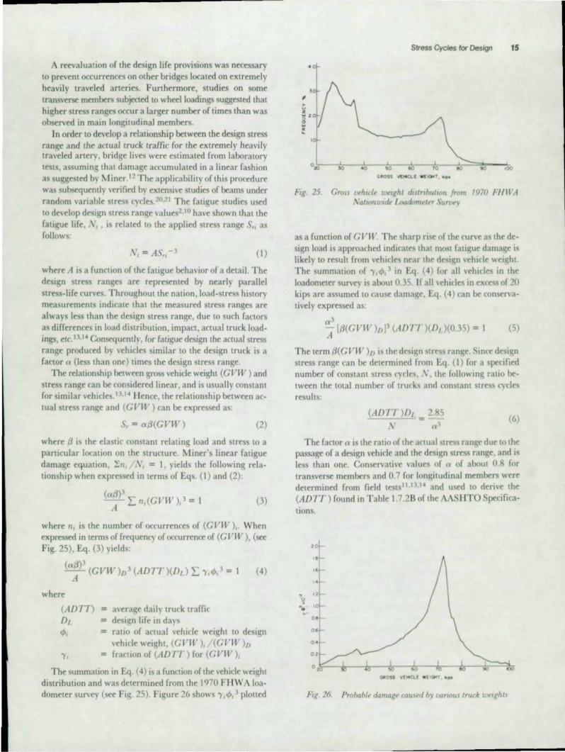
FIg . 18. M oment dIagrams (SI S.S)
2. Ai' HTO Anicle 1.7.2 indicates that for a redundant structure, for Case II Truck Loading (500,000 cycles) and for Category C (which includes nexural stress at the to(: of transverse stiffener welds on girder webs or nanges), the allowable range of stress ,,~, = 19.0 ksi (Table 1.7.28).
J" = 9.4 ksi < F" = 19.0 ksi o.k.
Notes: 1. The top nange is always in compression; therefore, a fatigue check of the lOp nange at the shear connectors is not necessary.
2. The span is less than 125 fI.-O in.; therefore, no lateral bracing is required.
DLSIGN EXAMPLE 2
Design Information:
1. Two span continuous 140-ft 140-ft ; load faclOr design redundant construction
2. Unshored composile construction (positive moment region only) ; welded pla.e girder
Design Examples 9
3. 8·in. reinforced concrete slab; 'h·ln assumed integral wearing surface not considered for composite prop. erties
4. HS20 loading 5. Dead Load 1: D. = 0.85 kips lin. ft (Weight of
concrete slab) plus estimated weight of steel s"'tion 6. Dead Load 2: D2 = 0.40 k.ps 1m. ft (static loads
applied after concrete has cured , carried by composite: section)
7. Girder spacing: 8 ft-O in. 8. Wheel load distribu.ion factors :
S / 5.5 (non-cydical and 2,000,000 or less cydical loads)
S, 7.0 (over 2,000,000 cyclical loads) 9. Fatigue Case I, AAS I ITO Article 1 7. 2
10. Steel : ASTl\l A588, "~. = 50 ksi 11. Concrete: j', = 3,000 psi ; n = 10 12. Bolted field splice at 1.71 poino of pan 1 and 2.29 pomt
of Span 2.
Design for Non-cyclical Loading:
The dead load and live load moments are as shown in Fig. 18. The live load moments are based on a wheel load distribution factor of S / 5.5 for the initial non-cydical design
Figure 19 shows the load factor girder design which sa.isfies the moment and shear criteria for dead and non-cyclical live loading. The remainder of this design example will involve analysis of the girder and redesign where necessary to insure compliance with all AAS I ITO fadgue specifications.
Design for Cyclical Loading:
This design example is for a heaVIly traveled arterial and IS
to be designed for Case I, Article I 7.2, where the design life number of cydes is 2,000,000 for truck loading, or 500,000 cycles of stress for lane loading, considering muluple lanes loaded. Members must also be investigated for S "7 for one traffic lane loaded. Longitudinal members should be checked for and satisfy the three criteria. The values of allowable stress range for redundant structures should be u~d in this cast, as a continuous multiple girder bridge is considered redundant.
Top Pia " It rz .!¥e:,_989Z'
)(- B'ot,~ 4~ ~'.o"_
SI.II,o. 50" 62' _6 4 6 7!>-r""""T--"<.-:"-. Spoci"9
fig . 19.
F" ld Seello" I
It IS. • 98 92'
Bolted t .• ,d IP IoC I
4 0' O·
II I II I I I I I }
Girder sectIOn reqlllred by load jactQr dcngn - dead and non-cycilcallwl! load

10 Bridge Fatigue Golde
Field testing has indicat<d that a wh<elload distribution factor of S '7.0, rather than S 5.5, more accurately reneets measured Slfas values. In some instances, this may still be conservative. This also recognizes the fact that for fatigue the vast majority of loading cydos arocaus«! by a heavy truck in one lan< only, ralhor than from hoory trucks in adja«nt lanos. The probability of having two lanos loaded simultan<ously with heavy trucks, each producing a maximum live load moment coincidentally, is extremely small. Stress history measurements have included stress cycles under a variety of load conditions and have indicated that S/7 was acceptable <von for infrequent simultaneous loading because of impact, variation in gros vehicle weight , and other related faclors.26
Therofor<, for fatigue analysis for Case I, a wh<eI load distribution factor of / 5.5 (mulliple lanes loaded) is used for live loading where the design life number of cycles is 2,000,000 for truck loading and 500,000 for lane loading. In addition, a footnOle to Ankle 1.7.28 indicates that members must also be inv<sllgated for over 2,000,000 stress cydes produced by a single truck placed on th< bridge (for a multipk girder structur<, a wheclload distribution factor of S/ 7 is used).
Combined tress Diagrams:
It is convenient to plot the ('ombined stress diagrams, i.e., the sum of the dead and live load str<SS<S for bolh top and bottom nanges. This wlil facilitate the fatigue analysis of the girder for items such as studs welded to top nange, transverse stiffeners welded to web, the bolted field spli«, fillet w<ld of web to nange, and lateral bracing. ote that the li v< load and impact moments due to truck lo..1ding are used here, since the allowable stress ran~e in fatigue , consid<ring the number of cycles, is much lower for truck lo.1ding than for lane loading and governs thIS d ign. Generally, both lane loading and truck loading must be checked to determine which governs. Th< combined stress diagrams for lOp and bottom nanges of pan 1 are shown in Fig. 20 for the S/ 5.5 dIStribution factor. Applicable values for a distribution factor of S/ 7 are obtained by decr<asin~ the values sho\\ n by the ratio 5.5.7.
The combined stress diagrams are constructed by plotting the combined maximum and combined minimum stresses at cach point of l'on('ern on lhe girder. The difference between maximum and minimum stress at a point renects the live load and impact strrss range, r ". The stress range may be computed directly from positive and negauove lane load moments or positive and negatiove truck load moments. Howeover, it is necessary 10 know whether the stress range is one of tensiont~tension or re\rrsal, in which case the fatigue criteria apply. The fati'IUe criteria do not apply for a range from compr<sslon-to-comprrssJon
Fali~ue Analysis of Stud Type Shear Conneelors:
The length of top nange O,"r which stud-type shear connectors arc installed is governed In fatigue by Stress Category C (Table 1.7.2A2). This permits the foll owing allowable stress range for truck loading Cr able 1.7.2AI):
- < • 0 ~ -
10
. ~ 20 • ., >-
'" ., ., '" 0: >-., o
'" z 5-30 ., ;;;
'" . o ~-2 <.> "
~ <.> -10
10 < o .. < 20 !!
30
• -'. Actual Stress Ranoa (f.,1
Top Flanoe
Bottom Flonoe
U l2 13 14 15
fig. 20. CQmbtnrd slrm diagrams (Sf,.,)
I. Multiple lanes loaded (2,000,000 cycles with S 15.5):
F" = 13 ksi
2. ingle lane loaded (ov<r 2,000,000 cyclos with 7):
r~r = 10 ksi
This example problem is composite in the positive moment region (Field ection I ). By inspection of the top nange combined stress diagram , the maximum stress range in the composite region is 3.9 ksi This range is always in compression and, therefore, fatigue is not of concern. ince the negative moment region ( Field Section 2) is non-composite by design choire, no stud shear connectOrs are required there.
If the longitudinal slab reinforcing in the negative moment rrgion was assumed to act compositely with the main girders (AAS IITO Arl. 1.7.63), shoor studs would have been required in this region (Art. 1.7.48) and lh< fatigue design specifications applied. In this caS<, the combined stross diagram would have 10 be computed on the basis of lh< composit< section properlios of the r<inforcing and th< main girder, and the tOP nange str<SS range kept wilhin th< allowable.
Fatigue Analysis of Toe of Transverse tiffener \-Velds:
Where transverse stirfencrs are attached to the web with fillet welds, Ihe allowable st ress range at the toe of the fillet is governed in fatigue by Stress Category C Crable 1.7.2A2).

..... =
i' Stiff."" r--- 60·
i' , •• - '" J
P=="'FI= Bottom Fla. \ 11
"""'.
48.6~·
fig. 21. Stress range at end oj stiffener near 1.6 tenth pornt
This permits the rollowing a llowable stress ranges ror truck loading:
I ~Iultiple lanes loaded (2,000,000 cycles with S 5.5)
F" = 13 ksi (Table \.7.2AI)
2. Single lane loaded (over 2,000,000 cycles with S 7):
F" = 12 ksi (Table 1.7.2AI, rOOtnote)
Berore analyzing the combined stress d,agram, firs, consider which of the above crileria will govern. To obtain the actual stress range ror ingle lane loaded, multiply 'he ac,ual stress ror muillple lane loaded by (.1'/7.0 + S,'5.5) or 5.5/7.0. The allowable stress ror single lane loaded is 12/13 or 'he allowable stress range ror multiple lanes loaded. Note ,hat 'he reduction is greater for the actual stress range than for the allowable stress range. Thererore. by inspec,ion, 'he multiple lane loaded condi,ion governs (F" = 13 ksi ).
T ransve~ stiffener welds must be term mated shan of the web.to.nange welds by a distance four to six times the web thickness (see discussion or stiffener de,ails in Chap,er I). The critical point in fatigue is the toe of the fillet weld connecting the stiffener to the web.
A group of trans\'erse stiffeners begins near the 6th tenth poin' or Span I (t.6 point) and continues '0 'he interior suppor, (2.0 poin'). First , ror Field Sec,ion I , note rrom 'he combined stress diagram ror 'he bollom nange ,ha, 'he maximum stress range over this region is 14 .2 ksi at the t.6 tenth point. Compute the stress range at this location as rollows:
Distance from extreme fiber of bottom nange to location under consideration (see Fig. 2 1 ):
Cse 6 limes thickness or web plus ,hickness or bonom nange plate:
(6 X 'I,.) + % weld + "',. bollom nange = 3.94 (sa)' 4.0 tn.)
(48.65 - 40) S'ress range/., = 14.2 = 13.03 ksi
48.65
Therefore, the actua l stress ran'l;c is dose to the allowable stress ran~c of 13 ksi at the location in qucstion. No increase in bottom na",~e size is required
Design Examples 11
Top FlonQ •
Sllf1.ne.,.-I--11
Bottom Fr.ange
FIg. 22. Stress rang!' at rod of stiffener near I. 71lt·nth pmnl
Inspection or 'he combined Slress diagram ror 'he ,op Jnd bottom nangc plates in Field Section 2 indicates a stress ran~e or 17.0 ksi in both lOp and bollom plates alt he 1.71 point. L'se the moment at this point in lieu or the moment at the actual stirrener location, as they are approximately the same. This is the point at which non-composite action is assumrd and the resulting Stttion properties are Significantly decreas~
Dislan~ rrom the extreme fiber to location under ron Iderallon (seo Fig. 22):
(6 X '/'6) + y~ + 1.0 = 4.0 in
j, (3 1.0 - 4.0)
Stress range " = 17.0 - -- = 14.8 1 ksi (31.0)
Thererore, ' he actual stress range exceeds 'he allowable stress range or 13.0 ksi at the location in question, and both top and bottom flange plate sizes must be increased
Redesign Field Seclion 2:
,.~.,. = 13 ksi (at point or stifrener weld termination approximately 4 in. rrom the outer flange surfaces)
A, 1.71 point:
The stress range for the flan'l;es necessary to insure that 'he stirrener weld complies wi,h 'he \3 ksi allowable IS :
F = "
(3 1.0) . 13.0 . = 14.93 kSl
(31.0 - 4.0)
Try top and bollom nangcs 18 X 1.00 in.'
S - _ 41 ,360 _ . 1
, - So - - 1,334 tn. 31.0
Top flange stress ran~('·
Q 36 + 1-,1 25..li.1 22 = _ 11 .34 kSl /m= = 1,334
j, __ ( 136 - 5()8~( 12} _ .
mm - - + 3.35 kSI 1,334
J" = [3.35 - (- 11.34)[ = 14.69 < 14.93 ksi o.k.

12 Bridge Fatigue Guide
Boltom flange stress:
Is,. = same as top nange stress :. o.k.
Area of nange plates required = 18 X 1.0 = 18 in.2
NOte that since the tOP nange plate is primarily in compression , the stiffener should nOt bt cut short, but should be left to bear on the lOp nange plate. However, it shou ld sti ll be coped as described previously, and the weld terminated six times the web th i kness away from the nange-to-web fillet weld.
At 1.8, 1.89, 1.9 and 2.0 points:
The allowable stress range at all these points is within the allowable stress range; therefore, no increase in plate size required at these poinlS. Figure 23 shows the area of nange required at each tenth point, as required by fatigue criteria (0 ) or by basic nexural criteria ( fl. ). A solution to this example for Field Section 2 is two plates as shown in Fig. 23, or one plate 24 X It/. continuous over the interior support. An economic evaluation should be made to determine whether or not a splice is justified.
Use plates spliced as shown in Fig. 23.
Fatigue Analysis for Lateral Bracing Connections:
Lateral bracing may be allached to the girder in several different ways. A simple and inexpensive detail would be a horizontal plate welded to the web at a calcu lated distance up from the bouem flange . This distance would be the location where the calcu lated Stress range in the web is less than the allowable stress range for this detail. The allowable stress range for a plate greater than 12 times the plate thickness or greater than 4 in. is tress Category E (Table 1.7.2A2). This permits the followin~ allowable stress ranges for truck loading:
1. Multiple lanes loaded (2,000,000 cycles with S/ 5.5):
Frr = 8 ksi
2. Single lane loaded (over 2,000,000 cycles with S/7):
Frr = 5 ksi
The single lane loaded with a llowable stress range of F" = 5 ksi governs, since (5.5/7. 0)(8) > 5.
For example, the location at which lateral bracing can be attached at the 1.7 1 point is found as follows:
The stress range at the 1.7 1 point, using the redesigned nange plate of 18 X 1.0, is:
j" = 14.69 (5.5/7) = 11.54 ksi (s ingle lane loaded)
By proportion , letting J equal the distance above the bollom nange at which lateral bracing may be attached (see Fig. 24):
o 030 ... 0:
... .... «
.. 24, 1.2j' II 96~ 30 ,..-- ---~
I " I " "
I\. Cyclicol Design (fotiQue! : J ",,"
~ 20 I~L~I8111112912 __ ---+ ,/' Ii.! " ,....,b"'; ! 10 I i --No;;-C;'~Qlo;.i9n==:~-:;-- ! .... I.&.. ,_---- ---'Y""'Non-Cyclicol I ~ 11., 1, I Demond Area '
« ~ o~~-----~------~-----~. .q 1.7 I 8 19 2.0
TENTH POINT LOCA TlON
F,g. 23. Flange redeSign
y = _3_1.0_ (11.54 - 5) 11.54
y = 17.6 in. (above the bollom of the nange to the point on the web where Frr = 5 ksi)
For some details , this may be tOO far above the bollom nange, and another detail should be chosen. B)' using a 6-in . radius and making the connect ion to the web, the allowable stress range increases to 10 ksi . Here the detail could be placed 4.2 in. above the bollom of the nange, based on a similar method of calculation. Another option would be to bolt a suitable detail to tither the nange or web, in which case Category B would be applicable and the member would be satisfactory. The actual choice of details is an economic decision. In some cases it may be more economical to add material and decrease the st ress range; in other cases special details which satisfy the criteria without changing material sizes may be lhe bett~r choice.
Analysis of Fatigue for Bolted Field Splice:
Proper sizing of the field splice material will satisfy Category B (Table 1.7.2A 1).
Fatigue Analysis of Flange/ Web Fillet Weld:
This condition is satisfied by inspection for the redesigned girder. All areas of the girder were analyzed ror fatigue and
far · 11.~4 k,1 r----1
-----+-
~ fSf · N.54 kli
rig. 24. POSlllOn on gIrder web where calegory E IS sallSfied

redesigned where neeessary. In 'he area of 'he girder where no Sliffeners or Slud shea r connectors are required (Field Section I) , 'he Slress range on 'he original design was well within 'he 18 ksi stress range allowed by Ca'egory B (2,000,000 cydes, S 5.5 governs), Table 1.7.2AI.
Fatigue Analysis for Lane Loading:
Table 1.7.2B indica,es that stress rangts caused by lane loading muSt also be inves,igated for 500,000 cydes (Case I). For Category C, F ... = 19 ksi for 'his case. Since 'he live load ,noments due '0 truck loading are only significantly exceeded by 'he live load moments due '0 lane loading be,ween 'he 1.9 and 2.0 'en,h points, only 'his area need be checked.
Top nange' F" = 19 ksi
BoHom nange: f~. = 19 ksi
A, 2.0 ,enth point:
Section propenies compu,ed are:
Design E,","",ies 13
= = 64,.156 in 4 = 2 053 in } S, Sb 31 .25 m. '
We need only to consid" the range of love load moments due to lane loading to determine the "tress range:
j, = (1 ,545 - 0)(1 ~ = 9.0 ksi < 19 ksi o.k. " 2,053
General Comments:
This example is for a homogeneous girder of A588 Sleel In hybrid designs, 'he designer should mvts,iga,e using Sleel wi,h a lower yield point in any nange pla,e where 'he nange sitt was increased due to fatigue requirements.
In load factor design, when a nange plate siu is increased due to fatigue "requirements, the ultimate moment capacity of the girdet is increasal Under cerlain conditions this may reduce the required shear capaci,y of 'he web. This would permi' larger Sliffener pacing, po sibly leading to fewer stiffeners and a more rronomiral design.

14 Bridge Fatigue Guide
CHAPTER 3
STRESS CYCLES FOR DESIGN
Overall, the history of both highway and railroad bridges has boen quite satisfactory. The failures that have occurred pointed out the importance of properly considering in design and fabrication the factors that innuence the fatigue strength of steel bridge structu res. Some ratigue crack growth has occurred in a few bridge structures and components. The possibility of fatigue cracking under relatively high stress range conditions was demonstrated by the coverplated steel beam bridges or the AASHO Road Test· More recently, cracks were observed in a coverplated bridge located on an interstate highway which carried an unusually high volume of heavy truck traffic,7 causing large numbers or cyclic stress.
Fatigue cracks have been observed jn other structures and their occurrence usua ll y resulted from cond itions that were nOt accounted for in design . These conditions have included: tack welds that were not incorporated into final welds, but were used during fabrication as means of temporary attachment; the addition of welded plates or attachments without considering their reduction in fatigue strength; unaccounted for out-of-plane displacement induced stresses; and details which changed the st ructures ' behavior, such as connections which provided fixity when si mple supports were assumed in the design . Many or thes\' laller types of failures have been due to oversights in either design or fabrication and account for most of the adverse behavior experienced.
Early fatigue specifications in the United States originated from railway bridge design, which required reductions in allowable st ress when members were subjected to load reversals· During the 1940's hoth AREA and MSHO adopted the A WS bridge specifications for welded structu res. These provided for three load cycle condi tions: 100,000; 600,000; and 2,000,000. Allowable stresses were expressed in terms of the maximum stress and varied with the stress rat io R, defined as the algebraic ratio of minimum and maximum stress. These provisions were based on a ... ai lable test data , mainly on small plate specimens, and 2,000,000 cycles was genera lly assumed lO be the run-out or infinitc' life condition.9
Little change in these provisions occurred until 1965, when new steel bridge ratigue provisions were adopted by AASHO. These provisions were developed from accumulated data from a variety or sources and a reexamination of older test data. Various types of condit ions and details were divided into nine difrerent ciassiocations ror fatigue lives of 100,000; 500,000; and 2,000,000 cycles. The allowable ratigue stress was still
expressed in terms of the maximum stress) with provisions for stress ratio and steel strength. In the t 965 provisions, some details and members were permitted higher allowable Stresses for high strength steels, whereas other details were not per· milled such increases.
Minor changes were introduced as further data became available and the data base increased. Many of the early fatigue studies were carried out on A7 and A36 steels, while more recent studies were concentrated on higher st rength steels. Because of this, some differences attributed to steel strength were more likely due to changes in welding techniques and improved experimental procedures, rather than the yield point of the material. Many past studies did not provide for an experiment design that would permit a stat is· tical evaluation. Hence, it was not possible to provide a sta· tistical analysis of the design factors that innuence fatigue st rength and determine their significance. Duplication was rare, critical variables were not controlled systematically, and the experimental error was not defined.
In order to overcome these limitations, the National Co· operative Highway Research Program supported a comprehensive study on "The Effect of Weldments on the Fatigue Strength of Steel Beams" at Lehigh Universily2. 10 These studies used statistically designed experimental programs under controlled conditions) so that analysis of the data could reveal the significance of the parameters believed to be important in fatigue behavior.
These studies and other work available in the literature permilted a comprehensive specification to be developed. 10
These provisions were orst adopted by MSHTO in 1973 and issued as Inlen'rn Specificalions- 1974. Revisions have been made in 1975, 1976, and 1977. Following is a brief description of the laboratory studies and criteria used to establish the current AASHTO Fatigue Tables 1.7.2A1 , 1.7.2A2, and 1.7.2B, shown in Appendix B.
Experience with actual highway bridge structures in the United States has demonstrated that fatigue crack growth can occur when a bridge is subject to extremely high volumes of truck traffic.7,11 This behavior is related to the fact that 2,000,000 cycles of loading docs not correspond to a fatigue limit or crack growth threshold for some structural detai ls, as was previously assumed in various specifications .2.10 Fatigue damage in some cases can occur from many cycles of low stress range.
A rttvaluation or the design life provisions was nettssary to prevent occurrences on other bridges located on extremrly heavily traveled arteries. Furthermore, studies on some trans-<rse m<mlxrs subj«t«l to wh«lloadings sugg<st«l that higher stress ranges occur a larger numbtr of times than was observed in main lom;itudinal members.
In order to devdop a rdationship Ixtw«n the design stress rang< and Ihe aClUal truck traffic for th< eXlremely heavily tra\leled artery, brid~e lives were estimated from laboratory tests. assumm~ that damage accumulated in a linear fashion as su~geSled by ~Iiner "The applicability of this procedur< was sul=qu<ml)' ,erifi«l by eXlenSt'< studies of Ixams under random variable stre; cycles.~·21 The fatigue studies used to develop des"~n stre')s ran~e values2.10 have shown that the [atigu< life, ,\ ,IS rrlat«l to the appli«l strrss range Sn as follows'
x, = ASn -' (I)
wh<r<: A is a function of th< faligu< IxhaVior of a d<tail. Th< d< ign Ir<s rang<> ar< r<pres<m«l by n<arl)' paralld stress-life curves. Throu~hout the nation , load-stres history measuremt"nts indicate that the measured Stress ranges are always less than the desi~n stress ran~e. due to such factors as diff<r<nc<s in load distribUlion, impacI, aClual truck loadings, <IC. 13·" Conscqumtl), for fati~u< desi~n the actual SlIT'<S
rang< produc<d b, ,ehicles similar 10 the de ign truck is a factor Cl' (Ies than one) times the design stress range.
The relallonshlp helw«n gross \thiele weighl (CVII') and tress range can be considered linear. and is usually constant
for similar vehicles. 1 "\.1<4 l ienee, the relationship between actual stress ran~< and (G I' ll ') can Ix expressed a •
(2)
where d is the e1a'itic constant relatin~ load and stress to a particular toration on the structure. ~Imtr's linear fattgut: dama~e equation, ~n S, = I, yields Ihe following rel,luonship when expressed in terms of Eqs. (I) and (2).
("~)' L n,(CI'II'),' = I (3)
where n, is the number of occurrences of (C I ' II' ),. When expressed In terms of fr<queney of occurrence of (C I' II'), (see Fig 25), Eq (3) yields
(a~)' (CVW ),,'(AD17)(DrlL"'r,t/>,'= I (4)
(A f) rl)
Df t/>,
= J\t:ra'l;e datiy truck traffic = dCSl~n life in da)'s = rallo of anual ,ehide wetght 10 desig;n
"htck wel~ht , (G I 'W ), (C I '11' )" = fraclon of (AD II ) for (G I ' W ),
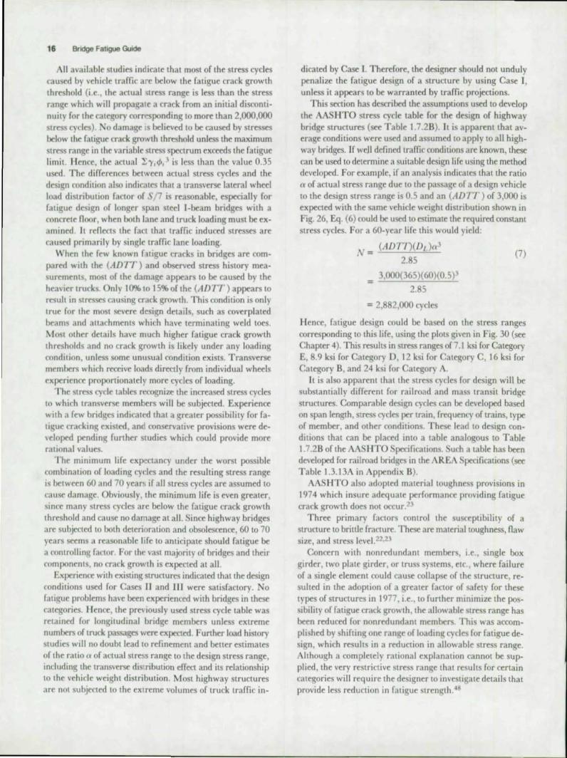
The summation In Eq. (4) Isa function orlhe vehicle wei2;ht distribution and wa, drtcrmlned from the 1970 ~ II WA loadomeler su"ey (see Fi~. 25). Figure 26 shows "'r,t/>, , ploued
•
, > u • w, ~ • -
Stress Cycles lor Design 15
rIg. 25. Cross l't'h,c/l' UNIJ!ht dIJlnbrltll)n jrnm IQ7n FilII' .... NalmnrJ.!,d~ I "1Ot/llmt'll'r Sun't'V
as a funclion of CI'W The ,harp rise of thr ('une as the deSlg;n load is approach«l Indicates Ihal most fali~ue damal1;e is likely to result from \·ehicles ne.lr the deo;;;i~n \ehlrlr wel~ht. The summation of "'r, t/>,' in Eq (4) for all \ehides In the loadometer u<'<) is about 0.35 If ,til "hid . in <X'<'o of 20 kips are assumed to ('<luse dama~('. Eq (4) can be ronsef\·atively expressed as:
J a ItI(G I'I\' )"I'(.1D11 )(1),)(0.35)= I (5) A
The term tI(CI ' 11 ')" IS the de'i~n SIr"S ran~e. Sin« desi~n stress ran~e can Ix delermined from l'q ( I) for a spettfi<d number of constant stress fyrles. S. thr foll()win~ ratio between the total number of tru{'ks ~1nd fonstant stress fydes results:
2.85 (6) :--,,'
The factor C\' IS the ratio of the anuat litre s ran'l;r due w the passa~e of a design vehicle and the de"~n SlresS range, and IS
less than one. Conservative values of (t or alxlut O.R for transverse members and 0.7 for lon~ltudinal members w("re determined from field test~II.I\.I<4 and u~d to dtri\t the (AD1 r) found in Table I 7 2B oflhe AASIITO Specifi('ations.
'0
"
, . • " " -. .. o. o. o. O.
OK • '" I<'
F'J!. 16. Probable t/amagt' mult"d bv hJr/oUI truck u.'t"'lfhtl
16 Bridge Fatigue Guide
All availabl~ studies indiral~ that most of the stress cycles caused by vehicle traffic arc below the fatigue crack growth threshold (i .e., the actual stress range is less than the stress ran~e which will propagate a crack from an initial discontinuity for the cat~ory corresponding to more than 2,000,000 stress cycles) No damage .s believed to be caused by stresses below the fatigue crack growth threshold unless the maximum stress range in the variable stress spectrum exceeds the fatigue limit. lienee, the actua l '5;"1,<1>,3 is less than the value 0.35 used. The differences between actual stress cycles and the desi'to condition also indicates that a transverse lateral wheel load distribution factor of S. 7 is reasonable, especially for fatigue des.gn of longer span steel I-beam bridges with a concrete noor, when both lane and truck loading must be examined. It reneets the fact that traffic induced stresses are raused primari ly by single traffic lane loading.
When the few known flligue cracks in bridges are compared with the (ADIT) and observed stress history measurements, most of the damage appears to be caused by the heavier trucks. Only 10% to 15% of the (ADIT) appears to resull in stresses causin~ crack growth. This condition is only true for the most severe design details, such as coverplated hcam(j and 3113rhmcnLs which have terminating weld toes. ~ l oSl other details have IlIU h higher fatigue crack growth thresholds and no crack growth is likely under any loading condition. unless some unusual condition exists. Transversr members which receive loads directly from individual wheels experience proportionately more cycles of loading.
The stress cycle tables rN."Ognize the increased Stress cycles 10 which transverse: members will be subjected. Experience: with a few bridl.';es indicat('d that a greater possibility for fatigue crarking e:xisted . an conservative provisions were developed pendlOg further studies which could provide more rational values.
The minimum life expectancy under the worst possible combination of loading cydes and the resulting stress range is between 60 and 70 years if all stress cycles are assumed to cause damage. Obviously, the minimum life is even greater, 'iinre many stress tydcs are below the fatigue crack growth threshold and cause no damage at a ll. Since highway bridges arc subjected to both deterioration and obsolescence, 60 to 70 years seems a reasonable life lO anticipate should fatigue be a controlling fatlor. For the vast majority of bridges and their components, no crack growth is expected at all.
Experience with existing structures indicated thatlhe design conditions used for Cases II and III were satisfactory. 0
fati~ue problems have been experienced with bridges in these categories. lIel1ct, the pre\iously used stress cycle: table was retalOed for longitudinal bridge members unless extreme numbers of truck passages were expected. Further load history studies will no doubt lead to rcfineme:nt and beller estimates of the ratio 0' of actual stress range to the design stress range, including the transverse dis'ribution effect and its relationship to the vehicle weight distribution. Most highway structures arc not subjected to the extreme volumes of truck traffic in-
dicated by Case I. Therefore, the designer shou ld not unduly penalize the fatigue design of a structure by using Case I, unless it appears to bt: warranted by traffic projections.
This section has described the assumptions used to develop the AASHTO stress cycle tablt for the des.gn of highway bridge structures (see Table 1.7.2B). It is apparent that average conditions were used and assumed to apply to all highway bridges. If weJ I defined traffic conditions are known, these can be used to determine a suitable design life using the method developed. For example, if an analysis indicates that the ratio a of actual stress range due to the passage of J design vehicle to the design stress range is 0.5 and an (AD 17 ) of 3,000 is expected with the: same vehicle weight distribution shown in Fig. 26, Eq. (6) could be used to estimate the required constant stress cycles. For a 60-year life this would yield:
=
(A 1J17)(1h )a'
2. 5
3,000(365)(60)(0.5) J
2.85
= 2,882,000 cycles
(7)
Hence, fatigue design could be based on the stress ranges corresponding to this life, using the plots given in Fig. 30 (see Chapter 4). This results in stress ranges of 7.1 ksi for Category E, 8.9 ksi for Category D, 12 ksi for ategory C , 16 ksi for Category B, and 24 ksi for Category A.
It is also apparent that the stress cycles for design will be subst3mially different for railroad and mass transit bridge structures. Comparable design cycles ran be developed based on span length, stress cycles per train, frequency of trains, type of member, and olhe:r conditions. The~ lead to design conditions that can be placed into a table analogous to Table 1.7.2B of the AAS II TO Specifications. uch a table has been developed for railro.1d bridges in the AREA Specifications (see Table 1.3.13A in Appendix B).
AASH TO also adopted material toughness provisions in t 974 which insure adequate performance providing fatigue crack growth does nOt occur.2)
Three primary factor. control the susceptibility of a structure LO brittle fracture. These are material toughness, Oaw size, and stress level. 22.23
Concern with non redundant members, i.e., single box girder, two plate girder, or truss systems. etc., where failure of a single element could cause collapse of the structure, resulted in 'he adoption of a greater factor of safety for these types of Slructures in 1977, i.e .. 10 further minimize the possibility of fatigue crack growth , the allowable stress range has been reduced for nonredundant mem\)(rs. This was accomplished by shifting one range of loading cycle for fatigue design, which results in a reduction in allowable stress range. Although a completely rational explanation cannot be supplied, the very restrictive Stress range that results for certain categories will require the designer to investigate details that provide less reduction in fatigue strcngth.48

Stress Range Concept 17
CHAPTER 4 STRESS RANGE CONCEPT
The fatigue strength of a particular structural joint has been evaluated in the past by tests on specimens that simu lated the prototype connection, or on smaller connections which were similar. Only approximate design relationships were developed, becau~ of the limitations of the test data.t5.t6 Often many variables were introduced into the experiment with a limited number of specimens, which made it impossible to
clearly establish the significance of stress conditions, details , type of steels, and quality of fabrication .
A substantial amount of experimental data has been developed on steel beams since 1967, under the sponsorship of the National Cooperative Highway Research Program (Project 12-7), which has shown that the most important factors that govern (he fatigue strength are the stress range and the type of detail .2·tO Stress range means that only the live load and impact stresses need to be considered when designing for fatigue. These findings were observed to be applicable to every beam and detail examined. Beam specimens were used to overcome some of the limitations of smaller simulated specimens. These beam tests and other work available in the literature were used to develop a comprehensive specification based on stress range alone.
A brief summary of some of the lest data is given here to demonstrate that stress range and type of detail are the two factors which are most likely to govern the fatigue strength.
IN ITIAL DISCONTINUITIES
Two types of welded plate girder details examined in the laboratory are reviewed in this brief summary: (1) the welded plate girder without auachmenLS and (2) beams with welded cover plates. Test data has demonstrated that all fatigue cracks commence at some initial discontinuity in the weldment , or at the weld periphery, and grow perpendicular to the applied stresses. In the welded plate girder without attachments, most laboratory fatigue cracks were observed to originate in the web-to-flange fillet welds at internal discontinuities such as porosity (gas pockeLS), incomplete fusion , or trapped slag. It should be noted that these discontinuities are always present, independent of the welding prooess and techniques u~ during fabrication . Identical behavior has been observed in the laboratory for longitudinal groove welds with either incomplete or complete fusion .16
The coverplated beam provides a structural detail in which crack growth starts at the weld periphery, where small sharp discontinuities exist at the toes of fillet and groove welds made by conventional welding processes.J,17 The fatigue crack in a coverplated beam, with or without transverse fillet welds, forms from these micro-discontinuities perpendicular to the applied stress.
References 2 and 10 contain a number of photographs of fatigue cracks. The~ photographs illustrate the various types of discontinuities that exist in structural joints. Under large cyclic stresses these discontinuities grow and eventually result in failure. The test data are described in the following discussion of fatigue strength.
FATIGUE STRlNGTIt
The test data for the welded plate girder without au"chmenLS and coverplated beams are summarized in Fig. 27. Stress range is ploued as a function of cyclic life for ~veral different levels of minimum stress on a log-log scale. It is visually apparent that stress range accounted for the fatigue strength for both structural details, i.e., minimum or maximum stress did not have a significant innuence on the fatigue behavior. The ratio of minimum to maximum stress, R I did not affect the stress range to cycle life relationship. The coverplated beam results included wide cover plates, thick cover plates, and cover plates on both rolled and welded beams.
No significant difference was ob~rved for either the welded girder or coverplated beam that cou ld be auributed to the type of steel when a given detail was subjected to the same stress range conditions. This is readily demonstrated in Fig. 28, where the resulLS are ploued for three grades of structural steel with yield stress ranging from 36 ksi to 100 ksi, representing the extremes generally used in bridge construction.
The data ploued in Figs. 27 and 28 show clearly that stress range is the critical stress variable for all structural steels. The results also confirm the significance of the type of detail. The coverplated beam only provided about 45% of the fatigue strength of the welded plate girder without attachments.
Studies on other details have also tOnfirmed that stress range alone is the only significant factor for designing a given detail against fatigue. Results on beams with transverse stiffeners, attachments, and transverse groove welds have also demon-

18 Bridge Fatigue Guide
ro .0
'"
•
,I I
001 01
'• 2 • ~ .
/--- ----~ . ~ ... c...t..:...c. L.... ..._- ....... '0' 9~'" s.", ... GI ... Co,.,jIIoI~ ,,",.,.
o. '0
..
Fig. 27. l:.1fect 0/ mln,mum ,·Iress and stress range on the cycle life lor the welded end of cOllerplated beams and plam welded beams
siralcd that minimum stress and type of steel are not critical factors.2•10 Groove welded splices at flange width transitions in AS I 4 steel were more severely affeeled by Ihe straighl lapered transilion . This led 10 Ihe requirement for a curved transilion for AS I 4/ AS I 7 sleel.
In a transverse groove \\cld with the reinforccmentldt in place, the st ress concentration at the weld LOC, with its associated sma ll micro-discominuities, is usually more severe than nominal internal discoOlinuilies. However, if lack of peneIralion , s lag inclusions, or other internal discontinuities are large in size, crack growth will become more crit ical at the internal loc3tionys, tb.18 In bridge construction, transverse
groove welds that are subjected to tension or reversal of stress are generally nondestructi\Cly lesled 10 prevenl large internal discontinuities from occurring. Also, the weld reinrorcement
--.. "I'q, .... on L ... 1.·16
- - t~, COftf_. L.'.'" 100' tS'4 s... .....
1. - 441
,~~ ____ ~ __ ~~~~~L-__ ~ __ ~~-L ____ ~ 001 Ot OS to • '0
C'l'ClU TO ''''UIf!£ I~I
Fig. 28. E1fecl of slrers rangp and type of sleel on the cycle "Ie 01 coverplaled and plam welded beams
'0 60
'" ' 0
Sf!lt(SS to .."" .. ,
- - 9:1"110 Conl,_. l, .... ' '0<,""110 S .... _
O'OL'~OL'----~--~~OJ...--~u'O~--~--~~-L~--..J..",
ClO.U TO 'f.ILUR[ 110- '
FIg. 29. Companson of short welded allachments Wtth couerplated and plain welded beams
is orten removed, so that the weld toe is not critical and a high ratigue strength results.
All evidence indicates that the termination or groove and
fillet welds provides a more critical crack growth condition tha n internal discontinuities in the weld . This is illustrated in Fig. 29 where Ihe lesl dala for Ihree Iypical welded details are summarized. The welded detail with the highest ratigue strength is the welded beam without attachments. The same strength was observed in groove welded nange splices.2 In these nange splice deLails, cracks normally grow rrom internal discontinuities that are perpendicular to the applied stresses. The other Iwo details shown in Fig. 29 are a shon altachment (4 in. long) and Ihe coverplaled beam. BOlh faligue strength relalionships were defined by cracks Ihal formed al Ihe end of Ihe auachment al Iheir weld loeS. When Ihe auachments were very short , as with a transverse slirrener, the ratigue strenglh approached Ihe strenglh of a welded plale girder. lo
For an attachment 4 in . long, Fig. 29 shows that the ratigue strenglh is aboul midway bel ween Ihe upper bound (welded beam) and Ihe lower bound (coverplated beam). Auachments longer Ihan 4 in. quickly approach Ihe lower bound condilion given by Ihe coverplated bea m.
The Stress range values given in Table 1.7.2A I were derived from Ihe 95% confidence limils for 95% survival. Rolled beams were used for Calegory A, welded plale girders for Calegory B, sliffeners and short 2-in .• uaehme",s for Category C, 4-in. allaehments for Calegory D , and cover plated beams for Category E . The stress range eyrie life relationships are ploued in Fig. 30 for each design category. After 2,000,000 cycles, Ihe stress range a pproaches Ihe crack growlh Ihreshold leye! ror the various details and becomes a constant value. For more than 2,(X)(),OOO cycles, the ract that transverse stirfeners are less severe than a 2-in. auachment is reflected by an allowable stress range or 12 ksi , which appears to be rcpresenlalive of the threshold level for this design condi tion.

Stress Range Concept 19
60 __ 1 ' 1 II i I r r"T TT ,
SO ----..;. I i ,
! ~ I I . t1 --- 1 • -r-+-·_··t ~ --.. r--i-- I I I 1 . ,
---- -- -- . 1 1 -- COltQory A
---- -............. r-'--1
2 ..;::: '-- - ------r--. ............ r-. ~ ....... COleQory B ...,
---r-. -;;t~-- COleqor~ C (SlIIlenersl
I - Cale90ry C (Other AlfochmenlS J l .+-t- -=' COleQor'f 0 ,
I-
-- ~-t +---:-+ COleQory E
.. ~ I I ~~ .
~. ~
; J ! L + ~
I 1 I
I I I I III I I , 10 " ~IIO • 2110
CYCLE LIFE
10 , •
FIg. 30. J){,Jlgn stre.u range CUrl 'l.'S j or Calt:goneJ A 10 E
RESIDUAL STRlSSlS
.\11 welding process('s result in high tensile residual stresses, which are at or near the yield point in the wcldmcnt and base metal adjacent to it These occur as the weld shrinks upon coolin~ . Thus, in the initial stages of fatigue crack growth in an as-welded structure, mOSt of the fatigue life occurs in regions of high tensile residual stress. L'nder cyclic loading, the material at or near the initial discontinuity will be subjected to a fully effective <)'C'lir stress, even in cases of stress reversal. This is the major reason why stress range alone is the variable describing the f3li~ue behavior of welded joints. As a result, the stress ratio , R , does not play a si~nificant role when describin~ the fati~ue strength of welded details. because the maximum stress at the point of fatigue crack initiation and growth is almost always at the yirld point. ~lost of the fati~uc life is exhausted by the time the fatigue crack propogates Out
of this hi~h tensile residual zone. An examination of the available data has shown that cracks
have ~rown in the tensile residual stress zones of beam flane;es subjected to cyclic compression alone. ~.6 However, these
studies also showed that the crack arrested as it grew into adjaccm rompresshe residual stress regions. No beams lost load carrying capability as a result of compression flange cracks unless out-of-plane bending stresses were introduced .
The existence of small cracks ronfined to the tensile residual stress regions of fOlllponents subjected to compression alone is analoe;ous to the compression splice proportioned LO carry only part of the member's strene;th. with the balance of this force resisted in bea rilH;.
As a result of this beha\'ior, the fatie;ue des ie;n criteria IS
limited to regions subjected to tension or stress reversal. If the member is subjected to stress reveNal , fatie;ue must be considered no malleI' how small the tension component of str("ss ran~e is , since the crack generat("d in a tensile residual slr("ss zone could be propa~ated to failure with very small compo· nents of the tension portion of the stress cycle
It is apparent that residual stresses play an important role in both the formation of cracks from dis('ontinuities that reside in the tensile residual stress zone dnd the arre~t of cracks ac; they grow into a compression residual stress zone of a member subjectcd 10 compression alone.
VARIABLE STRt.SS (\( LlS
The most widely used method to account for cumulative damage is the Miner hypothesis . I:!. Variable stress fyde
damage is at'CUmulatro in proponion to the relative frequency of occurrence of each level of stress range. Other methods have been proposed, but Miner's hypothesis is among the simplest.
In order to evaluate the si~nificance of random \'ariahle stress eyries and assess the applicabilitv of cumulauve damae;e criteria such as t\liner's Rule or the R~IS (root·mean-square)
procedure. a program of study was undertaken in 197 1 under the sponsorship of the National CoopermiH Ilie;hway Research Program (Project 12-12 ).~(J ·~ 1 The study was rarfled out at the Rcscar('h Laboratory of U. S. Steel Corporation on beams identical in geometry to those tested on Projen 12·7 at Lehi~h Univcrsity.2

20 Bridge Fatigue Guide
:: 30 .. .... . ~~~ ~ ... -.... .. ~.~ ..
L_ Conl.-.:;. L. i ... ,. [CO"'9Ol'J E I
o - t::::---.. -~
S., / S,., 00. • o Z5 0 ... 0 ". .
'0' 10' 10' CYClES TO rAILUR£
Fig. 31. Comparison oj uanable load tests with mean and lower confidence limll Jor Category E usmg Miner's
Rule (Ref 27)
'0'
The results of this study indicated that Miner's linear damage hypothesis and the RMS stress range both provided
'a means of relating random variable stress cycles to constant cycle dat3.20,21 An effective s~ rcss range can be developed using Miner's linear fatigue damage relationship In, I N, = 1 together with Eq . (1) (see Chapter 3) as:
(8)
where 'Y, is the frequency of occurrence of stress range Sn' The RMS stress range for a variable stress spectrum can
be defined a :
(9)
The results of coverplated beams tested under variable eyclic loading are plotted in Figs. 31 and 32 and compared with the mean and lower confidence limit given in Fig. 29 for constant eycle loading. Equation (8) was used to determine an effective Miner's stress range for the variable stress spectrum for the points plotted in Fig. 31, and Eq. (9) was used to determine an effective RMS stress range for the test points plotted in Fig. 32. The variable stress spectrums conformed to a Rayleigh distribution as shown schematically in Figs. 31 and 32. It is apparent that Miner's linear damage relationship and the RMS stress range both provided good methods of transforming the variable stress spectrum into an equivalent effect ive stress range. A second factor is also apparent at the lower levels of effective stress range. Several tests were conducted with an dfective stress range below the constant cycle fatigue limit. Some cycles in the stress spectrum exceeded the constant cycle fatigue limit and this apparently caused a ll stress cycles to
' 0
: ' 0
" • ' 0 z « • ~ , • ~
~ ~
'0'
M
0 0 ~COf'I~ U",,' [( '*OO<J C)
.~"-!.. •• '" MeOI' Rao'HI'ofI LI ...
''' o~ -j ',.
'., ' \. ·0 ~-~
I ,r\ , 's,. ' 025 /r~/S,.'O~ ~L~, rs.,"·IOO
S"'S,,,,
" "'" ~ .. , STM SS """'OE
, .. 0
I, • .....J~ '" 10' 10'
CYCLES TO f AILUR£
Fig. 32. Companson of lXlnabie load tests WIth mean and lower cO,lfidence "mit Jor Category E usmg RMS
effective slresHange (Ref 27)
",'
contribute to fatigue damage. The plotted points are seen to fall between the confidence limits. Hence, if no crack growth can be tolerated and extreme life is required, all stress cycles should be less than the fatigue limit.
CURRENT RESEARCH
Considerable research is underway in the United States and abroad on structural fatigue. Studies are conti nuing on the high eycle fatigue behavior of the lower fatigue strength details, variable stress cycles, curved girder details, methods to retrofit or repair fatigue-damaged members, the effect of environmental condit ions, and other related problem areas.
Studies on full scale welded bridge details, completed in 1976, indicated that full sized coverplated beams have less fatigue strength than implied by Category E.2' A comparison of this test data with results of studies on several bridges that experienced fatigue cracking shows reasonable agreement with the laboratory findings and field experience.25
Work currently underway on NCHRP Project 12-15(2) will provide a more comprehensive data base on full scale beams, so that an appropriate design category can be provided in the near future.
Stress history studies are continuing or are planned, so that the stress spectrum can be beller defined for both highway and railroad structures Most of the studies have focused on bridges of short or medium span length . The behavior of larger span bridges is now under study. Field measurements are also being made to help evaluate methods of retrofitting and upgrading older bridges.

Secondary Stresses 21
CHAPTER 5
CONNECTIONS - FATIGUE CONSIDERATIONS AS A
RESULT OF SECONDARY STRESSES
The Innuen("(' of ronnruing various components to the main load-("Mryin~ nlrmbrrs was discussed in dctail in Chapters I and 2. Various df"Sign drtails wert examined and their dfw on Ihe f,lligue strenglh of Ihe member was noted and deah wilh. The Sire" range r",uiLing from Ihe design load was used 10 wntrol tht drt,til r1tftion and location.
In add Ilion '" fOnlrol o\Cr Ihe detail seleCtIon and Ihe ailowablr Slrt'S, r.llu~:r .lpplirable to it, other factors mu,1 be lakrn Into arf(lunt if lhe p()~ibility of fatigue cracking is to bt minimizfd nr rliminau"rl. The interaction of the components of a Slru(1urt" In rrsponSt' 10 Ih·e load cn:ates secondary StrtSsc:s al Ihe ronnruinn,_ Thr ... r lO{"('ondary stresses must be provided for, 10 addillon "'Ihe mmpuloo primary Sires"",, when bridge connenl(lIlS are laelng deSIgned. In Ihis Chapter, Ihe effecI of secondary slr('''iS conditions not directly accoumed for in the dfsu~n art cli "fl!, std, and r«'Ommendations art pro\'lderl to
minimiz their efrrft.
RESTRAINT AT SIMPLE END CONNLcrIO~S
~fi.lny 'Imple rr~lmlne; ronnmions thal fastrn btam or ~irder rnds, such as \tnngcr-to-noor-beam connections, are usually considered '" lae fOlOpletel), Oexible and to carry shear only
Ilu"cHr, nn pr.lf"tlral r1\cted, boiled, or weldtd connection can be complelel), Oexiblr. Some resisting moment, or end reslr"lIlI, is ,llw,I)'S ""doped as Ihe connected parIS resistlhe rDlallun of Ihe end of Ihe beam. h s magnilude depends on Ihe relall\.e nrxibilaty of the ('onnection and the connected parts. End rotation ,It.1 imple framin~ connection cau~ dislort1on 10 onur, ," IlIu,araar" m h~. 33. Usuall) Ihe upper part of the ronnenion 1\ in (('mion while the lower pan is compr ~ against lht mcmber to which it is connected. This rnd T'OLalion i. a('(ommod,lled by Ihe di lora ion of Ihe an~les and deforrna"'," 10 Ihe fa tenrr. (bohs or welds). TypIcal momentrotation run.c\ for vtral end connections art shown In Fig 342"211 Thclic- (une~ demonstrate the end ~stralnt orrertd by \j]flUUS Ix)hrrl ronnt<·tiom. Two undesirable conditions can de'vrlop at "'Implr end" tOnneclions. One results from drformation of Ihe fOmponenlS, as shown <chematically 10 Fig. 11 The <;('('Ond '\10 cr<uiL from Ihe reslralOl and resullln~ end moment.
Gage
Fig 33 f)lio"nalwn of llandard bt!am rlJnnnllQn
End moment M(in Ib)
, , ,
o
c
B
I 2
~ ". L .11<::._...l.!:...._~=--'_'_'_,..:"...,G'-A_ Rotation, "(radian.)
h .l!. J.I l\;/Jlwl momt'tl/-l0I11lmn ("un I and b am Im"l
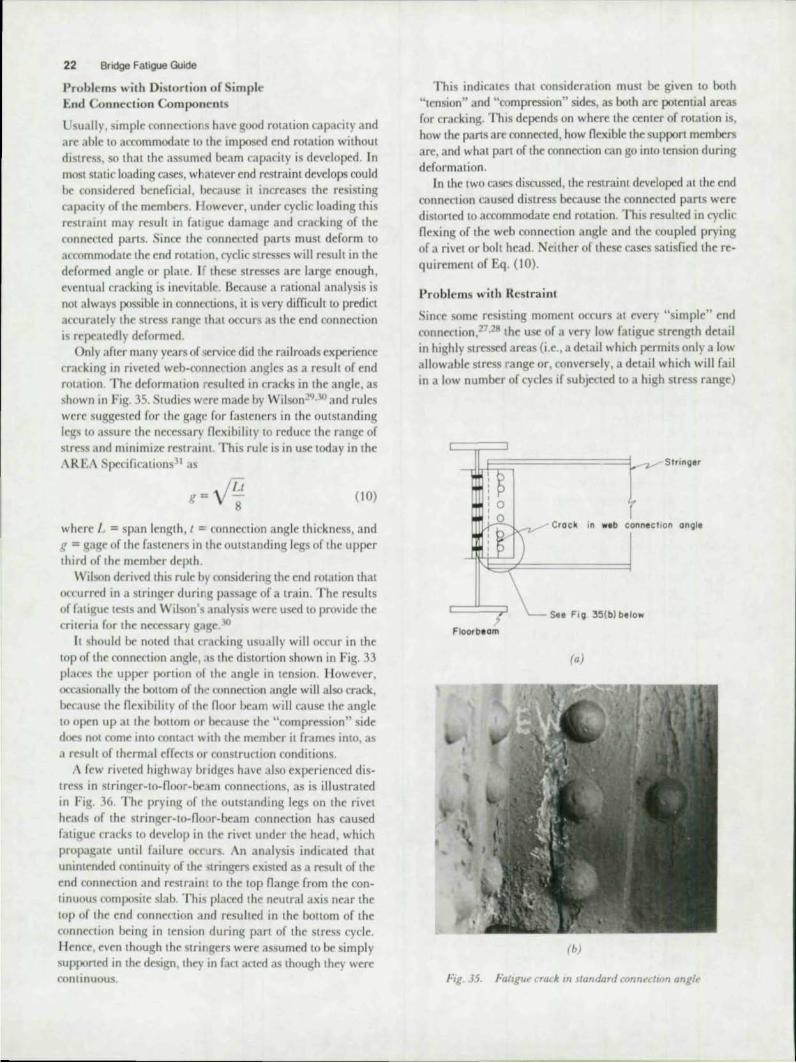
22 Bridge Fatigue Guide
Problems with Distortion of Simple End Connection Components
Usually, simple connections have good fOlalion capacity and are able to accommodate to the imposed end rolation without diSlress, so that the assumed beam capacity is developed. In most slatic loading cases, whatever end restraint develops cou ld be considered beneficial , because il increases the resisting capacity of the members. However, under cyclic loading this restrain! may resuh in fat :guc damage and cracking of the connected parIs. Since the connected pans must deform LO accommodate the end rot31ion, cyclic stresses will result in the derormed angle or plate. If theso stresses are large enough, eventual cracking is inevitable. Because a rationa l analysis is not always possible in connrt1ions, it is very difficult to predict accuratt"ly the stress range that occurs as the end connection is repeatedly derormed.
Only aftcr many years of service did the rai lroads experience crackin~ in riveted web-connection angles as a result of end rotation. The deformation resulted in cracks in the angle, as shown in Fig. 35. Studies were made by Wilson29 ,30 and rules were suggested for the gage for fasteners in the outstanding legs 10 assure the necessary nexibility to reduce the range of stress and minimize restraint. This rule is in use today in the ,\REA Specifications" as
g=VLl
8 (10)
where l. :; span length, I :; connection angle thickness, and g = gage or the rasteners in the outstanding legs or the upper third or the member depth .
Wilson derived this rule by considering the end rotation that occurred in a stringer duril.g passage of a train. The results of fatigue tests and Wilson's analysis were used to provide the criteria for the necessary gage.30
It should be noted that cracking usuall), will occur in the LOp of the connection angle, as the distortion shown in Fig. 33 places the upper portion of the angle in tcnsion. Ilowever. OC'tasionally the boltom of the mnnCCLion angle will also crack, because the nexibility or the noor beam will cause the angle to open up at the bollom or because the "compression" side does not come into contact , ... ith the member it frames into, as a result of thermal effects or construction conditions.
A rew riveted highway b, idges have also experienced distress in stringer-to-Ooor-be~lm connections, as is illustrated in Fig. 36. The prying or the outstanding legs on the rivet heads of the stringer-IO-noor-beam connection has caused fatigue cracks to develop in the rivet under thc head, which propa~ate until failure occurs. An analysis indicated that unintended continuity of the 'Stringers existed as a result of the end connection and restrain t 10 the top Oange from the continuous composite slab. This placed the neutral axis near the lOp of the end connection and resulted in the bottom of the connertion being in tension during part of the stress cycle. Ilence, even though the stringers were assumed 10 be simply supponed in the design, they in ract acted as though they were continuous.
This indicates that consideration must be given to both "tension" and "compression" sides, as both are potential areas for cracking. This depends on where the center of rotation is, how the pans ar connected, how nexible the suppon members are, and what pan of the connection can go into tension during deformation.
In the twO cast'S discussed, the restraint developed at the end connection caused distress because the connected parts were distorted to accommodate end rotation. This resulted in cyclic nexing or the web connection angle and the coupled prying or a rivet or bolt head. Neither or these cases satisfied the requirement or Eq. (10).
Problems with Restra int
Since some resisting moment occurs at nery "simple" end conncction,27.28 the use of a very low fatigue strength detail in highly stressed areas (i.e., a detail which permits only a low allowable stress range or, conversely, a detai l which will fail in a low number or cycles ir subjected to a high stress range)
_ ILE;:::;=========t..-:IV Strlnger
Crock in web connection on91e
See FI9 3!i(b) below
Floorbeom
(a )
(b)
fig, 35. Fat'gu~ cradr. In standard ronnecllOn angle

witlinV3rtabiv Itad to crackin~ from dislonion and restraint. An txample is the ta5(' shown in Fig. 37, wherr a stringer web is welded to a noor Ixam connection plate. Restrained rotation at the ends of the simple span stringers has resulted In high I"'nding stresses at the ends of the web shear ronncction Fillet welds ronnrct 'he beam web to a transverse staffenrr plate which IS, In turn. wrlded to the noor lxam web and (.'0111-
pression nange. Restraint from the connection caused nack growth In the stiffener plate, as illustrated, other comparable details Iwe exhibtled rracklng in the beam web as well. Weld tcrminJtions occur 311hr top and bottom of the connect ion in the hi~hest stressed re~i()ns,
Insufficient Ixndin~ f:apatl\)' in the connected mmena\ 1S
another reason for \'('n high stresses when restraint (K"C"urs. If the nange of the strin~er is a"umed to ha>e the same area a the web. the seoion modulus. S~, of the stringer IS approximatdv 7/f{! 6, lIowc\cr. by removing both nJn~e to pro\lde a lap splice of the web and ronncction plate, the Scctlon modulus i reduct'd to less than Itll 6. ) lem'e, resistance to
bending has been redu(~ b\ about 85%, whICh substanllally
, , . stringer.
r = Crocked rive t head.
Floorbeom
(a)
,
(b)
fig. 36. Crac/ud m el headJ from C)'t-be ~nd rr)lal,on
Secondary Stresses 23
increases the. stress ram;e In the "flU"\ stru<:\ure. the lab continuity will obviously (rdute thr Slrrv'es and mll1imlZe displacement brcausr of partialmmposilt' ~lnion. but lhi .. is often not enough to prevent fali~ue rr.l(k ~ro\\"th.
A rdated problem fan de\ clop at holttd fonnefllons. SU( h an ~xamplo " ,hown In Fi~. 18. I kre, ('r;\( kin~ has de'eloped at tht end of a strll1~er whifh \\"ilS hlU;h- tren~th-h()lled at ~l
"simple" w('b an~1r mnn('uinn to the noor beam. Cra(k growth has.develnped from the nnnllnal '\ompre\sJ()n" end of the connett IOn, where the stnn~('r n<ln~e was roped to provide clearance for the noor bC;II11 ni.lm~(' Sinre only one nan~e was toped, the bcndill,( re..,I'it.tllf(" of the cross section was (('duted to about 30% of Ihr ()ri~lIlal hendin~ rr islanct.
Becau .. e of the ('O~, the fonn('( tum end re"tralnt fau rd.l bendin~ stress ran~(' to C)('fur.tI the ("{.pr th.u was more than thrce tlmtS ~realer than it wuuld h.l\e be("n with tht nanu;t Intact Cra(kin~ dC\e1oped I""au'< "nn~cr ronttnuity and differential floor beam den('("tion dCH'\oped tell"iion durinll; IXlrt of the stre", cyde, .ind al ... o h«'.wo.,e t('n"'lle ,treS'-f· near the
~ . J A ,
S .. Fig 37(bl below
(aJ
(b)
rill- 37 Cradt '" 1/,f!l"nf·r rlalt· o! Ilnnl!f"r-to-f/om-lJt'am nmn('ctwn

24 Bridge Fatigue Guide
yie ld point due to name ('ulting wou ld exist at the point of crack initiation. Rderence 2 has demonstrated that a name-cut edge parallel to the stress is comparable to Category B details. The st ress concentration atlhe COpelO is likely to reduce this to Category C. Mter the crack has propagated through the zone of tensile res idual st ress, the principal tens ile stress resulting from the end shear and restraining momem is large enough to continue propa~ating the crack.
The cases cited have shown that the restraining moment at
simple end connections C,-In result in crack growth. Large bending stress ranges werr developed tn both the welded and high-strength-bolted end ronneaions because the cross-section resislan~ was substantially reduced.
Summary and Recommendations for Simple Connections Subjected to Cyclical Loads
If a beam is designed as simply suplX>rted , the end connection should preferably have minimum restraint. H owever, although welded lap connections such as that shown in Fig. 37 do not develop restraint much greater than is developed in bolted bearing-type web crnnections or seated beam connections, such lap connections should not be used for cyclically loaded beams because they have weld terminations in undesirable regions.
A bolted connection can result in unusually high bending stress ranges in the web if the nanges are removed near the connection . Where it is anticipated that hi~h cyclica l stresses will occur, Fig. 39 shows Ihe preferable way of con nect ing simply supported end members, If it is necessary to cope a flange in order to provide clearance, then an auxi liary flange should be welded to the web, or web shear plates should be
f lf!.38. Cracked web at ;) unple strmger end connectIOn from restraml and reducnl bending resistance
added , to increase the bending resistance of the cross section. Figure 39 shows these two possible solu tions. The bending resistance of the member should not be permitted to decrease by more than 50%. This will normally provide adeq uate fatigue st rength. If an auxiliary flange plate equal in size to the nange is used , this criteria will be sat isfied,
A number of steps ean be taken to minimiii: the possibility of cracki ng in the angle legs. The angles should be as thin as practicable, consistent with the reaction shear requirements, and the gage of the outstanding legs should be la rge, particularly near the ends of the connections where the deformation is greatest. The AREA rule developed by Wilson30
_ ILL g: V -
8 ( 10)
for the top one-third of the member depth provides a large gage in the tension region of the outsta nding legs of a simple web angle connect ion. A gage la rge enough to satisfy the requirements for railroad service will not be requ ired for highway bridges, as less end rotalion should occur. Based on the same criteria used by Wilson, a gage of vi Lt/ 12 would appear reasonable for most highway bridge structures. If an analysis indicates thal tension can be present in the "compression" region during the stress cycle, this criterion should be provided at both ends of the connection , Figure 40 shows a suggested fastener configuration that should minimize the possibi lity of cracking end connect ion angles.
~~lf::~=-:-:::O----I : ~.' 0;.;: '., '::, " , , I ~~ '.' I ,") :
::. I I ;: ':': '.) : ,.~: .:" '.) c,:
L--~~4Jj~~---~ -~ ~=;:::fF~==L;;--. I- ~
A (0) Web Doubler Plotes
B
Sect ion A-A
~bl (c) Bent up Flange Plate
Section B-B
(b) Au,;lllory Flange
PrOVide adequote bending reslstonce on section A - A
See F lg.40 fo r gage of outstanding legs for an91es
f ig. 39. Recommended connectzons where stnnger flanges must clear floor beams (see fIg. 45a for strmger connectIOn)

Properly tightened high-strength bolts loaded in shear are not subject to faligue failure. Properly lighlened high-strength bolts loaded in tension will seldom have Ihe bolt crack wilhin Ihe grip below the nut, providing prying aClion has been taken into accoun\. The 1976 RCRBSJ specificalion for A325 and A490 bolts32 provides design criteria for this type of cyclic loading. Of major importance is the level of fastener preload. If Ihe bolts are not properly lightened, any cyclic loading (with or without prying) can cause a significant variation in the cyclic Stress in Ihe threaded region. I[ Ihc bolt is tightened at
or above the minimum preload, the threaded arc~a will not experience the large variation of stress that would occur in a fastener with lillie or no iniLial tension. Hence, any bolt subjected to cyclic tension from direct loading or from distortion of the connected parts should be tightened to at leasllhe minimum preload specified.
DISPLACEM~NTS AT STRINGER CONNECTIONS AND WEB BRACKETS
Stresses that are nOI directly related to Ihe primary calculated stresses, nor to the restraining characteristics of the memixr, are of len introduced into a structural detail. These stresses are mosl often produced by unaccounted for out-of-plane displacements. Cracks formed as a result of these displacements generally do not adversely influence the member's strength, nor the perrormance or the structure. They may create maintenance problems and, ir not treated, may eventually lead to more serious raugue damage.
Flange Twisting and/ or Lateral Movement
Flanges of stringers are often subject 10 rolalions which result rrom the deOection of ties, in the case or railroad or mass lransit bridges, or Ihe deformation of nexible decks of highway bridges. Al end connections, angles and brackets are allached 10 the web. These allachmenlS are usually detailed wilh small gaps between the tOP of the allachment and the stringer top nange. Thus, the cenlral porlion of the web is strongly restrained. which forces reverse curvature to occur in the web above the attachment, below the twisting nange.
Figure 4 1 shows an example of web cracking Ihat occurred in the web gap at a simple rraming connection. End connection
f--..==-;:=::::::i:=;-L.1 ,----I Upp.r Iturd
o 0 : of m. mb. r
0 0: , 00' , 00:
9- lt/e
o 0 , , 0 0 '00 0'1'111 whl n . ubjl tled
to rlvl r. ol-lowlr
third o r ml mb. r
fig . .10 Recommended configuration oj oUlJIandmg legs uf w"ple end connections (a/so see FIg. 450)
Secondary Stresses 25
angles bolted to a rolled beam web resulted in a Y.-1Il unstiffened portion of the web. DeOetlion of ties placed near the end connection caused relative!) small Out-or-plane displacements to concentrate in this Sp.:1ce where bending stirrness is small.
The out-of-plane bendin~ moment 10 the web at the tOP of the attachment is given by.
'1 4/;/0 6f:/.!. " =--+ L L'
(II )
where the displacements 0 and.!. are defined 10 Fi~. 42 as the rolation of the nange relative to the web and the oUI-or-plane movement or the web. 'T'hls or tourS(" assumes a fixt'd end condition of the web at the connection. ConSidering a unit strip of web, the resulting stresses In the web are
,1/ II; [ 0 6.!. ] u= = 4 + S 21. L
( 12)
It is apparent that the oUI-of-plane web bend 109 stress is ><1)
sensitive to the unrestrained length of web, t, and the mode of displacement that is imposed For a g'\fn displacemenl and rotation, ir the length I is doubled , stress due lO rotallon is decreased 50% and stress due to displacement is decreased 75%. If 0 and ~ are rree to increase when L is increased, stresses will also be increased. or course, a cycle or Slress occurs with the passage of each wheello.d .
T lU
iJ'·J·~ 0-.1., ~"=j
o o
o o
o o
o o
o
o o 0
Section AA
A
Prc· .I 1. Sch~mat'c of web cradling from /langt' rotatron

26 Bridge Fatigue Golde
Similar dirficulties have been experienced when stringers rest on noor beams or noor beam trusses. Brackets attaching the noor beam to the sirine;er web may cause out-or-plane mo!"ement 10 concentrate in the stringer web as a result of denection of the slab, shortening of the compression nange of
Web QOP L
F'g, .12. &hematrc of Qul-aj.p/ane de/onnattOn In gap length
-.
Floor beam or Floor beam Truss
See FIg 43(b) below
(a)
(bJ
fig . ./3. Cmck In slmrger web above a web bracket
the noor beam, or lateral movement of the slab. Figure 43 shows a cracked stringer web above a bracket. \Veb bending stresses at the web-flange fillet ha .... e caused cracking to occur 31 the restraint point.
The problem of out-of-plane displacement can be particularly acute when significant horizontal forces develop in structures on cunes. These forces can cause additional nange movement relative to the web.
\Vhen very large or unrestriCted deformations occur, it may nO! be possible to provide enough length of unrestrained web to accommodate the forced rotations and displacements and , at the same lime, satisfy the requiremcnts of Eq . (12) at an acceptable level of Stress. A case of this type is illustrated in Fig. 44 , where end diaphra~ms framc into the stringer web. I !ere a nexible slab has induced large nange rotations and a 6-in. gap was inadequate to prevent cracking at the end of connection angles .
"
\
• : ' . ,
~ !
( J 'I
-
-,.;, Floc
I
r be om or Floor bea m Truss
See FIg 44(b) below
(a)
(b)
fig. 44. Web cracking at cut-short web stIffener

Recommendation .. to 1inimize the Effects of Out-of-Plane ~ lo\emen t at Stringer Connection.,
To o,ereome 'he pos"bili,y or cracking as Illustra,ed In Figs. 41 and 43. a liberal "~ap" dimension should be provided . so that th~ ddormation art not forc~d to occur wilhin short len'l,hs. cau'in~ hi~h localized strains and high ou,-or-plane web bendin~ 'res r\ . The required gap distance to keep 'he str~ss range within tolerable limits is d~pendcnl on the web ,hickness and 'he m.'~ni'ude or 'he displacements 0 and ~. For estimating fatl~ue performance, the unrestrained region is comparable '0 de,ails or Ca,e~or)' C ror a welded Slrin~er and Catrgory \ ror a rolled beam. If i, is possible '0 eSlIma'e 'he ma~ni'ude or n and ~. 'hese values should be used '0 establish the required length or ~ap. Since deformations will occur wuh the passage or each .lXle load . most SlructUrts will need '0 mee, tht allowablt str~<;; ran~e requiremtnts for 2,000,000 ~trrss cycle . althou~h he",11 tra,<Ied brid~es should be desi~ned for O\;er 2,000,000 "itress cydes.
In many struc,ures. ir 'he actual magni,ude or 0 and ~ is restricted. bu, difficult to es'ablish with assurance. a gap ien'l'h or abou, 4 in. is recommended. as illustra,ed in Fig 45a. When derorma,ion is no' ""Ir-Iiml"n~. as ror example by imple span ~nd rota lion of a noor beam, resistance 10 th~ dtformation should be provided. i\s no,ed earlier. requirements ror rtstrain,
0 0 .0
0 0
0 0
=-
0 0
0 0
0 0 0
=
Tie or flexIble J,/'" .Iob (,. "", Q"dl
- T Gop - 4 ln
Nott Ol l ploClmlnt l:J. WIll In
erton on curvt' or whtrt hOrizontal forclS dlvtlop
(b) Restrain flange movement when e and 6 ore not
restricted
FI,/! J.5 Rt'cnmmolfled ((ln nec/ton treatment whm tnp flanl[£-mf){'cment musl be conndered
Secondaty Stresses 27
to deformation can be particularly drmandin~ on curvts or where SI~nifican' hOrizon 'a I ror<-es arr developed Figure 45b shows one possibili,y. A second an~i< placed on each side or the strlm;er web, with ou,standln~ J~'S weldrd to the tringer nange. will provide sufficient out-or-plane re.istance. Care should be exertised to insurr th.u thr lies are placed over thr outstanding I~. otherwisr a st'\<'trr mndition can d~vdop in 'he stringer nange. Considera,ion should ai,,, be given to 'he displacements at the adjacent lie
A similar rendition can devrlop allhr slrin~er connections a' floor beam roadway relier joints. as was shown in Fig. 44 . , ufficient resi"ance could be pro\lcled by eXlendin~ 'he stringer ronneftion and atlachln~ it to tht nan~es, as shown 10 Fi~ 46. which prevents ou,-or-plane movement in 'hr strim;er web.
The coped diaphra~m in h~ . 46a is not sensillve to 'he problem shown in Fi~ . 38. ('.onlinuily across 'he stringer conneellon is prO\.ded by 'he slab. and 'hi . keeps 'he neutral axis near 'he cope. Because Ihe bending stress range a' 'he cope is small when ('ompartd to thr C'Ondition shown In Fi~ . 38, it is nOt necessary to reinfor~ thr ropt shown In Fig. 46a This has been verified by u('cessful ~rf()rmanc:r In the fidd at numerou romfh1rablt ronditJon",_ If ~hrar ronntc1ors art nOt installtd to insure composit{' .lC"tlon. the tOJX'd lOp nan~e is a weak point. and the alternate drtatl shown in Fi~. 46b should be used . In 'his de,ail . only 'he mnneCled side or 'he n"n~e shou ld be cu' and chipped away. so ,ha, adequate bendin~ resistance will be available in the dlaphrae;ms.
,0 ,
Stttl GrId FIIXlblt Slob
CompoSltl Qchon btt .. ln slob and dlaphro;m
'0
'o: i<o==-- j Block and chIp
Wild sMrlner to both flon; ..
(01 Slrlnger End Connecllan 01 D.ophragm
\
t Non - composltl Ilob
t F
(b) Slrlnger End Connecl.on - CuI and ciJp flange whenever diaphragm carnes port of raodwoy laod.
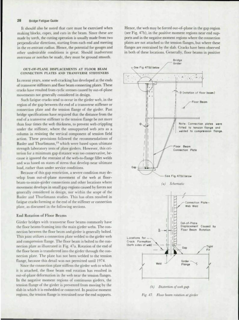
28 Bndg. Fatigue Guide
It should also be no,ed ,ha, care must be exercised when making blocks, copes, and 'UIS in 'he beam. Since 'hese are Ill,-Ide by lorch, the cutting optraLion is usually made from two perpendicular dirrctions. starting from each end and meetin~ in the fe-cntrant radiUS. lienee, the potential for gouges and other undesirable conditions is great. Shou ld inadvertent o\erruns or notches Ix made, they must Ix ground smooth.
o T-OF-PLANt. DISPLACEMENTS AT FLOOR BEAM (ONNECT'O PLATES AND TRAN VERSE STIFF~NERS
In reren' years, some web crackin~ has developed a"he ends or transverse stirreners and noor beam connecting pla,es. These cr.l,ks h,,,e resulted rrom cyclic stresses caused by ou,-or-plane movements not ~('nerally considered in design.
Such rJII~ue crack lfnd 10 occur In 'he girder web, in 'he rf~jon of the gap between l~e end of a transverse stiffener or (onnee,ion pla,e and 'he ,ension nange or 'he girder. Past brtd~e specloralion, ha>e required ,ha'lhe distance rrom 'he end of a transverse st iffener to the tension nange be nOI more 'han rour limes 'he web ,hi .. kness, '0 preven, web crippling under the stirrenrr, where the unsupported web acts as a column in resisting: the verdcal component of tension field .l(IIon. These pro>isions rollowed 'he recommenda,ions or Basler and Thurlimann.19 which werc based upon ultimatc strclU;th laboratory lests of plate girders. Il owever. this criterion for" mlllimum gap d.stancc was too conservati\ic, because il i~nored Ihe restrainl of the web-to-flange fillet welds and was ba'if'd on 1.,lts of stress that de~c1op near ultimate load . rathrr than under service conditions.
Uccau"it' of this ~ap restrinion . a severe rondition may de~elop from out-of-plane n'ovcment of the web at noorbrdm-to-main-girdcr connef"tions and other locations where mO\iement dC\ielop"i in small gap regions caused by forces not generall) ('onsidrred in desl~n. nor within the scope of the B,,, ler and Thurltmann s,udies. This has or'en resulted in fati~ue crarks formin~ al the end of the stiffener or connection plate. as dis(ussed 10 tht' followin~ sections.
Enel Rota tion of Floor Beams
Girder bridg;cs wilh tranwrl'')c noor !>eaml! commonly have the noor tX'ams framing iot the main girder webs. The connenion between the noor bc<-'m and ~irder i\ ~enerall" bolted. rl'hi., joint utilizes ~l nmncclion plate welded to the girder web and mmprcssion nange. Th.> noor beam IS bohed '0 'he conn('rllon pl~H(, as illu ~trated i" Fig. 47a. ROtation of the end of the noor beam is transferred IOta the girder through the connection plJte, The plate hal, not been welded to the tension naml;c, berJuse this detail was not permitted lImil 1<)74.
Since the l'Onnenion plate stiffens the girder web to which it IS allathed, the noor beam end rotation has resulted in oUI-of-plane deformation in he web near the tension nanges. In the n~'Hive moment rec;ions of continuous girders. the u~n'\ion nJn~e of the girder i ... prneoted from movin~ by the slab in whi('h it is embedded or conncctcd. In positi\e moment r~ions , the tension nam~c is r'estra ined near the end suppons.
lIenee, 'he web may be rorced ou,-or-plane in 'he gap region (see Fig. 47b). in the posi'l\e moment regions near end suppons and in the negative moment regions where lhe connection plates are nOI attached '0 'he 'ens ion nanges, bu, where these nanges are reslrained by Ihe slab. Cracks ha\t been observed in both of these locations. Generally, floor beams in positive
Bridge /" Glrd.r
,> • , ' ..
e (rotollon of floor beam)
.r Aoor aeom
~
f~'I===i;f=== 9
Locollons for Cr ack Formotlon (both Sides of web)
(b)
F,g 47
Not. Connecllon plates w.re 'Ilted 10 t.nSlon flange and w.lded to comp" ulon flong.
Connecllon Plate
See Fi9- 47{bl below
(a) Schema/IC
Weld">
I 'I
f-Connection PlateWeb Weld
Out- 0'- Plane DIsplacement Caused by Floor Beam Rotollon
/)UlortlOn of web gap
Hoor beam rotatIOn al grrder

momtnt regions that art not ntar tht tnd reactions do not develop as much out-of-plane nexing of the web, or a relative displaCf'ment in the gap region, due to the ability of the entire girder to ac(Ummodate this rotation by deforming with the noor beam. Whether or not this region can !Jerome" problem depends on the lateral stiffness of the girder nange.
There ha\'e been c;everal instances where the usual distance of Ih-in. to 2 in. between stiffener wtld termination and the web-to-nange weld has resulted in very large web bending stresses and caused fatigue crack growth, as illustrated in Fig. 48. The problem with out-of-plane movement in the web gap
A
.. ~ . '. '. . • • ••
Crock I
Sect,on A-A
L See Fig 48(bl below
ra)
(bl
FIg . ./8. Cradling In u~b gap al floor beam.to.glrdtr conntcllon plale In nel~alu..~ moment rt'gum where connectIOn p/alt:!
Wert' nfll u'chkd 10 tenswn flang~
Secondary Stresses 29
can be particularly acutr with skrwed bridges. rhe noor bt:ams art usually perpenditular to the main girders. whi(h may cause even larger deformation to ou:ur in the web gap region because of additional ('nd rotations due to differential 1 .. erlical mo\emenl of (he girders at each end of the noor beam.
The severity of the out-of-pl.,ne mOlement can be seen from Eq. (12). Considering only the out-of-plane mOlement , :', and assummg the web gap and web thickness are '/,-in., an outof-pla ne movement of only (l.OOGI 111 wi ll result m a web bending stress of 18 ksi.
ometimes, when a very small ~ap has been provided, the wtb cannot move appreciably ()uH)f-plane relative to the nange:', This can be benefi('ial , pro\'idln~ suffi<:ient \\'e:'b-('onne('tion weld is available to resi~t the resultin~ forces. \,,",here this is not the ca~. the weld cracks and the:' conn("('tion platt is peeled away from the weh. I:.\'entuall" this also r('sults in web cra(kin~ as a sap develops when the plate is pulled away from the web.
Also, extending the stiffcntr welds all the way to the ~trder web-to-nange weld may u('~lIe und(,~l rable conditions becaust' of weld shrinka~e. With 'h"k n,lIl~es. the restramt to tontraction is great and the strdin will tend to conc(,ntrate in the small gap. This results in hi~h tensile re"idual str('s~es which ('xist prior to any Out-or-plane bendm~ stress. On o('casion these ('ondilions have resulted in abo\{' a\{'ra~c initial dis(,l1nlinu ities and cracking.
T ransverse Stif(t itct!
Cyclic out-of-plane bendin~ stresses can also ottur durin~ handlin~or shipping as a result of the relati\'e rotation Ixtwttn the web and the nange. "fhe extensl\ eness of crack form.Hion depends on the girder size, how the girder is handlrd, what method of shipment is used , the trip lenl(th. the del\re< of (',cii, swaying motion that develops while in transit (due to the trlli nner in which the girders were supported and to roadb('d condilioN')' and other factors that result In repeated c:ydes of out-of-plane web bending strtss. Sneraimstanc:es of unsatisfaclOry performance and web trackin'{ have CKTurred from these causes.
Figu re 49 sholVs a sehom .. ic of a cracked lVeb at the end of a cut-shon stiffener. The cracks have formed at the weld toes
w ••
Sh"
c •• c~ .. SIlt!
Note . Manual weld ing C.ad
around endl 01 at/1 - £ fene,. I I unnec ... ory and can Ini t iat. cro cking.
Cross SectIon Elevotlon
f i,l[ . ./Q. Schemallcofcrm-kjmnalwnat(.ndoftram.t.Tlt.!llfl •. ner

30 Bridge Fatigue Guide
"
'h'ClI I" Movelll''''' o f To, "on1'
F lange Restrained
'oO
T'O,.cIOfl" 01 S'n .. ~I. C,ack
•
FIg 50 Scht'mallc Jhnu'lng ae/ormallOn oj web betu'I!tn end oj j tif/env and /langt: L,hcn lal"al JUlay occurs
at the end of the stiffener Figure 50 illustrates the typ< of deformation that \ViII re ull from sway of the girders on rail cars or trucks or differential rocking of rail cars as they move through switchyards or over poorly aligned or superelevated track, This is esp<eially true of long girders which extend over se\cral car lengths, and ran occur with girders that are well supponed and secured, enain handling procedures can also rrsuh in twisting of nanges. Near support points, twisting of the nange may occur during handling and shipping,
Once the girder is plat'td in the structure, the gap regions al vertical stiffeners are not susceptible to out-or-plane: movements unless lateral bracing or diaphragms frame into the stiffener. Laboratory studies33,34,35,36 have shown that pumping, due to out-of-strai~htness of the web in the middle of panels between transvers<: stiffeners and to the movement of thin webs under ~rvi(e loads, will nOt result in flange cracking when slender webs are designed according to the current specifications
To minimize the possibility of web cracking due to shipping or handling, consideration shf)uld be given to terminating the stiffeners a greater distance away from the web-to-nange welds. in order to increase the' web gap at the end of the stiffener. Between four and SIX times the web thickness should be used, This will not innuence the service behavior of the girder,
In addition to the CUI-short stiffener terminating four to six tim('s the web thickness away from the web-to-nange weld, provisions shouJd be madf' to mimmize the effects of lemporary loading conditions which could result in relative rotation betwren web and nange, This ran be accomplished by driving steel wed~es under stiffeners at suppon points, or by using short bearing stiffeners, i e" ; tiffeners properly fitted to the nan~e and extending some distance up the web.
It should be noted tha t "lI~ht fit " stiffeners, which allow a t/win, gap according to A W • will permit approximately the So.1me relative rotation to occur as will CUI-short stiffeners. li enee, even with Utight fit " stiffeners web-lo-stiffener welds should termimue four to six times the web thickness above the web-to-nange weld,
When one-sided stiffeners are used on very large girders, consideration should be given to the us<: of panial length shipping stiffeners at the suppon points, These ran be attached 10 the web and fitted to the bottom nange, The objective of thes<: stiffeners is to provide support during transportation.
Summary and Recommendations for Floor Beam Connect ion Plales and Transverse Sti ffe ners
One method of preventing or minimizing local displacement of the web, as shown in Figs, 47a and 47b, is to weld the connection plate to the nanges, Figures 5\a and 51 b illustrate this appl ication. Obviously the stresses in the flange must be selected so as to avoid fatigue failure from the weld toe, The design stress range must satisfy the applicable stress range provided for Category C, The composite aCllon of the noor beam and slab in highway bridges causes the neutral axis of the noor beam to be at or near the coped nange hown in Fig, 5 \ a, Hence, no significant bending stresses develop in the cop< region and the problem illustrated in Fig, 38 should not develop,
Bolting a connection angle to the wrb is another viable alternative. )fowner, care should also be t:xcrcised to provide the prop<r web gap length ; as Fi~, 41 has demonstrated, cracking can dc, clop from bolted connections as well. This is particularly true of welded girders, where the web-nange fillet provides the same condition as a welded connection plate. Without proper web gap length, crackin~ ran ocrur with either bolted or welded connection plates.
Figure 52 shows a recommended noor-beam-IO-girder connection for a through plate girder railroad bridge, The noor beam bracket connection plates and imermrdiatc stiffeners
N
L 21n or 4 fw
• •• (a) Floorbeam oc tlnQ
co mposi te With slob
R . 'U
r_-_-.. , , , , I I , I I I ~:.--
(b) Floorbeam Without
composite ac tion
Fig. 5 1. Recmnmefidedjloor beam connectIOn plates for negaiwe moment reglorls and nea r {'n d JupportJ

,; ! • <; !! ~ ~
" ,
• • • -0 c • • c
• • • • • .. ~ c .!!
.E E ~
.E "0 ~ .. !!
Co ) Detail at Flaorbeam brocket
Secondary Stresses
..
Cb) Deta il at Intermedia te
stiffeners
31
Frg. 52. Suggested floor·lNam-lo-gzrder connecirons
have a large gap (about 6 in.) bel\veen their ends and the floor beam end connections. The large gaps and the continuity of the exterior stiffeners insure small out-or-plane movements at the end of the floor beam connection plates and intermediate stiffeners. ear the supports, for a distance at least equal to the girder depth. the outside stiffeners should be welded to both top and bottom flanges. This will prevent any significant web bending stress from developing at the stiffener ends, as the flange is anchored and prevented from moving laterally.
SUGGLSTED GENERAL PROCEDURE FOR DESIGN OF CONNECfIONS
t . After fo.mpletion of the f rarning system, a systematic study should be made to discover all possible differential movements. both denection and rotation. This requires a deliberate training in visualization of structure action.
2. Details of connections between members subjected to these differentia l movements should be examined carefully. II is axiomatic that accommodation of the movement wi ll be made at the point or weakest resistance to bending. One or the fo llowing procedures shou ld be considered ;
a Detail the ronnetlions to provide a nexible point that can deflect without being overstres~d, or
b. Eliminate the flexib le points and design the connections to withstand the rorces that would occur .r the connection were rigid
3. After completion of details, stud) areas of high secondary stress for stress raisers, i_c ., welds, copes, elc.
4. Consideration should be gi,en to Vibration of long slender bracing members and the connections drtajled to avoid high cyclic stresses. (See Chapters 6 and 7 )

32 Bfldge Fallgue Guido
CHAPTER 6
SECONDARY MEMBERS AND CONNECTIONS
Diaphragms, lau."ral bracing and other auachmenl5 are used ('xtcnsivc:ly in bridgt:'S. Generally these members an: considered 10 play minor or secondary folc:s in the slruclUrr's pr:rfor~ maore. Of len, signific.m problems have developed because Ihry wrrr nOt properJy considered in the structure's overall bth;l\ior.
DISI'LACIIMENTS AT DIAPHRAGM AND CROSS-FRAMES
Diaphragms and cross-fram" are frequently used in multiple beam bridg~ to assist in erection and construClion, as wdl as 10 cfislribulr loads lau'rally in the structural system. 10 rCCCn! yrars it has been the practice to connecI the diaphragms and frm;lI·framt's 10 Ihi" longiturlinal members by means of a con· neclion plate that i. shop welded to the girder web and comp,"",ion flan~<, and field bolted to the cross members. Adjattm to the ten. ion flangr, the connt"dion plate is eilher fitted or cut short.
1\' the SIruCture is loaded, Ihe longitudinal girders may deform differenl amounts at he cross section where the diaphra~ms and eros. -fram .. are installed_ This can resuh in Ihe secondary mem~r displrtcing (he girder wens out·of-plan(' \ as ,hown schematically in Fig. 53a. The differential beam displacement, Ii, can be relatively large in skewed bridges whirh have diaphragms or cross-frames perpendicular 10 the longiludinal members. Of rourse, the ma~nllude of the oulof-plane web displacement, ~,is related to the relative girder displacement and the lateral hending resistance of the girder fl'lOl(e. ear supports where DOt member is deflected and Ihe othrr is not , relattvely large deformations can be introduced inlo Ihe girder web.
Figure S3b shows the cracking that devdoped in the girder web at an il1lermediate diaphragm in a skewed railroad bridge. Thr me-chanism or ratigue crack formation IS similar 10 that at Ihe ends of floor heams. The gap provided was I 10 2 in. between Ihe end of the connection plate weld and the webnange welds. In m,IOY inS1.1nn' this IYpe of rracking developed in only a frw fran, becau~e the out-or. plane weh bending sters,",s were vory large, parlirularly in skewed bridges.
To some extent Ihr prohlems which have developed at noor beam and diaphra~m conneNion plates have arisen beeause IranS\it'rse ",riding of attachments to (eosion Oanges was prohibited. This requirement was intended to reduce the likelihood of fatigue ITack growth in the flange. Recent rrsearrh has shown lhat the restriction of Iransverse welding on
0
ot 0
0' 0
ot 0 I 0
01 I 0
'
, 0
I I 10 , 01 I I 0' r :) r I
, I 0: I , I
~ =\ I I \ j __ t_
[, , ~. • F , 53bbtlwf( Se 0 (J 0 0
e ,ac1un9 at hon~vefSl dlophr09m wlb connection pia Ie
-
(a) RetorllO(' deformaiton
,
_0.
(b) Cracking at iransl¥!rse diaphragm web ronnt'chon plate (ItnL~d 6ndg<)
Fig. 5,), De/ormatIOn HI mU/II-beam bnd~e
p
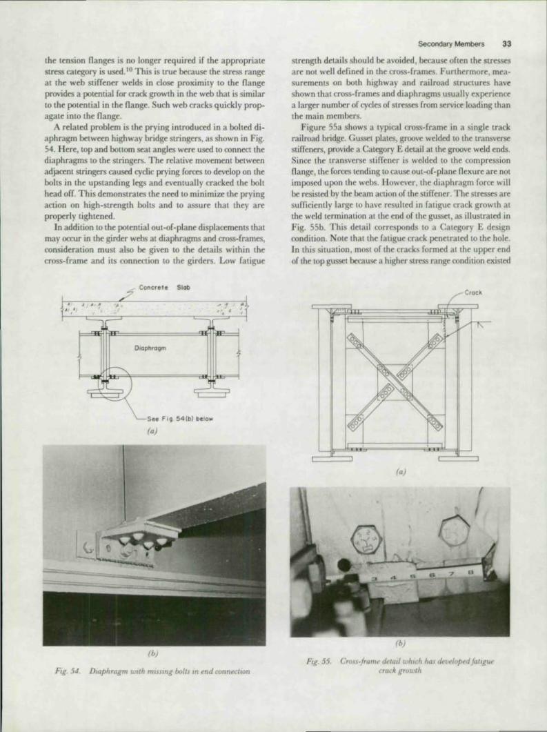
tho «nsion nang .. is no longer required if the appropria« stress category i.s used. 10 This is true becau5t thr Stress range at the web stiffener welds in clost proximity to the nange provid .. a potential for crack growth JO the web that is similar to tho potontial in the nango. uch web cracks quickly propagate into the flange.
A rdat<d problem is tho prying introducod in a boltod diaphragm botw«n highway bridge stringers, as shown in Fig. 54. Here, lOp and bottom seat angles wert used to connect the diaphragms to the stringers. The relative movement between adjarent stringers caused cyclic prying forC<s to develop on the bolts in the upstanding legs and eventually cracked the bolt head ofr. This demonstrates the need to minimize the prying action on high-strength bolts and to assuro that they are proporly tighten<d.
In addition to tho potential out-of-plane displacements that may occur in tho girder webs at diaphragms and cross-frames, consideration must also be given to the details within the cross-frame and its connection lO the girders. Low fatigue
Concrete Slab
DI(lphrogm
See FIt~ 54 {b) be low
raj
(b)
Flg.5J DIaphragm u.'IJh musing bolls In ~nd connt'cllOt1
Secondary Membefs 33
strength details should bo avoided , boca us< of .. n tho str«s<s are not well ddined in the cross-frames. Furthermore, measurements on both highway and railroad structures have shown that cross-frames and diaphragms usually cxpencnfc a larger number of cycles of str= from s<rvice loading than the mai n members.
Figure 55a shows a typical cross-framo in a singi< track railroad bridge. Gusset plates, groove weld<d to the trans .. "", stiffeners, provide a Category E detail at tho groove wold ends. Since the lransverse stiffener is wolded to the compression flange , the forces tcnding to cause out-of-plane flexure are not imposed upon the webs. J lowcvt'r. the diaphragm for~ will bo r«isted by the beam action of the sliffener. Tho str= ar< sufficiently large to have resulted in fatigue crack growth at the weld termination at the end of the gusset , as illustrated in Fig. 55b. This detail corresponds to a Category E desl~n condition. Note that the fatigue crack ponctratod to tho hole In this situation, most of thc narks form<d at the uppor end of the tOP gussel b<cause a higher stress range condition existed
Crock
raj
(b)
FIg. 55. emu-framt' dt' lali u·h,ch has dt,{,t'/fJpt'd tU IIP (' erato. gmu,th
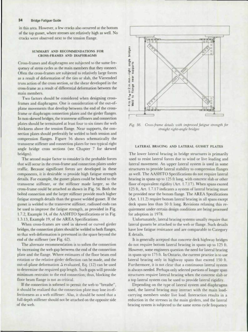
34 8Jidge Fatigue Guode
in this area. Ilowever, a few cracks also occurred at the bottom of th< top guSS<:t, wh<n: stn:sses an: n:lativdy high as w<lI. No racks wen: observed next 10 the tension nange.
SUMMARY AND RECOMMENDATIONS FOR CROSS·FRAMES AND D1APURAGMS
Cross·fram<s and diaphragms ar< subjected to th< sam< fn:· qu<ncy of stn:ss cyel<s as the main m<mb<rs that they connttt. Of"n th< cross·f rames an: subjected to relatively larg< forces as a result of deformation of the ti<s or slab, th< Vi«<nded truss action of the cross section, or the shear develoJXd in the cross·fram< as a n:sult of differential deformation b<tw«n th< main members.
Two factors should b< considered wh<n d<signing cross· fram<s and diaphragms. One is consideration of th< out·of· plane movements that develop between the end of the crossfram< or diaphragm conn<:ction plat<s and th< gird« nang<s. In non-skewed bridges, the transv~ stiffeners and connection plates should b< t<rminated atl<ast four to six times th< w<b thickn<ss abov< th< t<nsion nange. Near supports, th< con· nwion plates shou ld preferably b< welded to both t<nsion and compression nanges. Figun: 56 shows schematically th< transverse stiffener and connection plates for two typical right angl< bridge cross s<Ctions (so< Chapter 7 for sk<w<d bridges).
The second major factor to consid<r is th< probable for«s chat will occur in the cross-frame and connection plates under traffic. Because significant forces are developed in these components, it is desirable '.0 provide high fatigue trength d<tails. For <xampl<, the gusset plates could b< bolt<d to the lrans\'crse stiffen«:r, or the stiffener made larger, so the cross·frame could b< allacht-d as shown in Fig. 56. Both the bolted conn<ction and the larger stiffener provide much higher fatigu< strength d<tails than the groove welded gusset. Ifth< guS~t is welded 10 the transverse stiffener, radiused ends can b< used to improve the fatigue strength, as provided in Fig. 1.7.2, Exampl< 14 , of the AASHTO Specifications or in Fig. 1.3.13, Example 19, of the AREA Specifications.
When cross-frames are used in skewed or curved girder bridg<s, the conntttion plates should b< welded \0 both nanges, so that web deformation is prevented in the space b<yond th< <nd of the stiffen« (see Fig. 62).
The alternate recommendation is to often the connection by increasing the web gap between the end of the conn<etion plate and the nan~e . Where estimates of the noor beam end rotation or the relative girder denection can be made, and the out·of·plane deformation.l evaluated. Eq . (12) can b< used to det<rmine the reqUIred gap length uch gaps will provid< minimum restraint to the er:d connection; thus, blocking the noor beam nangt' is not as critical.
If the connection is softened to permit the web to "breathe", it should be realized tha t the connection plate may lose its ef· fectiveness as a web stiffener. Also, it "lhould be noted that a full d<pth stiffener should not b< allached on the opposit< sid< of th< web.
FIg. 56. Cross-fram~ d"w,ls With Improl.'f!d fotrgu~ strength for straIght nght-angle brIdges
LATERAL BRACING AND LATERAL GUSSt.T I'UTES
The lower lateral bracing in bridge structures is primarily used to resist lateral forces due to wind or live loading and lateral movement . An upper lateral system is used in some structures to provide lateral stability to compression nanges as well. The AASHTO 'peci fications do not require lat<ral bracing in spans up \0 125 ft long, with conuete slab or other noor of equivalent rigidity (Art. 1.7. 17). When spans ex«ed 125 ft , An. 1.7.17 indicates a system of lateral bracing must b< provided near the bollom nang<. The AREA Specifications (An 1.11 .2) require bollom lateral bracing in all spans except d<ck spans less than 50 ft long. RevtSlons relaxing this reo quirement under cenain design condilions are bemg processed for adoption in 1978.
Unfonunately, lateral bracing systems usually require that lateral gussets b< allached to the web or nange. uch details have low fatigue resistance and are comparable to Category E details.
It is generally accepted that concret< deck hIghway bridges do not require bollom lateral bracing in spans up to 125 ft. How<ver, some engineers question th< n«d for lateral bracing in spans up to 175 f1. In Ontario. the current practice is to use lateral bracing only in highway spans that exceed 150 ft . Furth«:rmore, it is not rlear that a continuous lateral system is always n«ded. Perhaps onl), selected ponions of longer span Struetures require lateral bracing when the concrete slab or a top lateral system can b< used to provide lat<ral rigidity.
Depending on the type of lateral system and diaphragms used , the lateral bracing may interact with the main loadcarrying members under Ih,t load. Interaction results in a reduction in the stresses in the main girders, and the laleral bracing system is subjef\ed to the same stress <yele frequency

as tho gtrtkrs to which it is attached When tho lat .. al sy"om InlrranS with the main v;irders. the lI\c load stresses must ~ induded in the invesli~ation of the lateral braC'"ing ('()nne('tlons for fauguo prrformanre. USIng tho <amo criteria as applIed to thol\lrdors. Of ton the latoral bracing system has bttn d I ~ned
for WInd loadin~ only The eyde frequency and prrmis.ible stres rane;e rnav not impo"Oc as much restriction on the ron· nection desi~n
A lateral system that does not Interact with main loadcarrpng members under traffic will nOI be as senSili\it' 10 Ihe connMlons used at the ends of the lateral members. Iloweser. the attachments to the main members must ob~ious)y be considered
OUI-of-Plane Movement at Lateral Gusset Plates
E\en when a lateral bracinv; system is provided that minimizrs mteractlon with the main load-carrying members under traffic. mall mo\ements will occur at the gus tt mooeclio" The« mult fmm tho denMed shapr of the structurr and can be rdati\ e)) larv;e when differential ... ertical deformation ()(cur~, In addition. most lateral bracin~ systems are buill with members thaI are nOt svmmctrical sections. For example, alU;les and structural tees a~ commonly used, li enee, when axial fortes are developed in the lateral bracing system, a rOtation OCfurs at the ll;usset becauS(' the neutral axis of the
. -.J. -.~~-~~~~=1 ==~~=== - r -;. _- __ _
u .. .L, __ JL_--,
(a ) Lateral connection plate at vertical stiffener
(b) Laterol plote welded to stiffener
(e) Lateral plate with transverse member bolted to stiffener
FI~, )7 \', ht mall .~hou In~ ~HHblt' fllJl-()/-plant!dIJplac~mt·nlln U,t·b and lat~ral,~llHd at lranH'('rlt!' stl,f/olf'r!
Secondary Members 35
member and gusset do not coincide (The full errontrinty is not effMive bemus< of the noxlbdlty of the mombers.) Relallvo deformation of the lon~itudinal memlxn may al~ fau~ out-of-plane movement of the gusset This is panlcularly true at gusS('ts near supports where one end of the lateral bracing member is prevented from movin~ venically. whe~as its other end displaces with the ~ ircl er Rel allv.t~ ,hort stiff latoral bracing members will ('ause the efrccls of this movemtnt to concentrate in the gu~set, 3tthe gap reglons .eo'! and).1llO Fi~, 57. These two factors rccentrirlly of Jo.,d and relall" deformations can cau~ deformatlon of the gU'i~t. a ie; shown sc hcmatically in Fi g. 57a
Another factor may he mnstrun ion tolerances, The force lincs from the latera l systcm may nOt exactly intrrsttt at the \ ... 'cb center line and this fan fau"e the gus~t to twist at thr web. as shown in Figs. 57b dnd 57< Tho d'"l= of doformation depends on the cross-frame fonn«tion as well.
Whon the gussrt plate is wtlded to the ~lrder wtb and transvrrse ';tiffcner as ~hown in Fi~. 57b. or the tran~Hr~ member is bolted to the trans\lcrS(' stiffeneNi. out-or-plane movements fan become trlll('al ~H the end of the tran~verse stiffcnrr, in the gap gl In addition, the i~nlficantt of \ertical movement at tho gussrt ,,"I be deprndtnt on the ~ap len~ths g, and g,. Very shon ,hstances Jre undeSirable. as they wi ll result in large bendin~ stresses in the gu srI at the wdd lines and at the end of 'he lalCral members.
If thr gusset is not mnnccted to the trans\{"r<ir stiffener as shown in Fig. 57c. part of 'he oUl-of-plane movement willi", aecommodaJed bv 'he wcb In ~ap l;'. If the ~ap IS vervsmall. >ery la"le web bendin~ stresses (an be intmdured lOto the ~ap re~lOn . llence. a roasonable ~ap Icn~th IS de'lrable Sh~ht" la"ler out-of-plane mmement' may develop with la"l"' ~aps. 1xt .. 1Use- not as much of the tran';\t'NC-sliITenrd web IS brou~ht into play. ""'hen the transverse bra('tn~ membtr frame, into the ~ussrt plate and 'or slIffener. as ,hown in Fi ~ 57c. ne~ligible out-of-plane mo,cmont develops lO the web sp.1(·e I! •. When onl~ diagonal members frame lOto the ~u et plato. out-of-plane movemcnts arC' likrly to be ~realer, as the force lines may not interscn, Only gaps I!:' and I!' are q-nsiti\e w vertical movement or the gusset pIalI:' ,
Figure 58 shows a cralk that dr\dopcd at ~usSt'tS that were not wcldC'd to the transverse sliffC'l1C'r The lateral gusset plates wcre wdded only to tht' web on each Side of a trans\'("rsr stiffener. Ilere it is a l<;() dear that the wob ~ap. g •. between the end of lht" lon~itudinal ~usset plates <md the trans\er stiffener, is \cry small, Ilen('(', Jny out-of-plane deformation at the web a. the strunurr defonns will rt'Suh 10 \er\' high weh bendlOg straIns. In thIS cxample. tracks developrd afteronl) a few years of service
The ~sS('t connMlon shown lO Fi~ 58 also created a sesere restraint problem at the IOtercoef1l0n of tht" Innll;itudmal and transverse stiffener welds. Th("\(' interstttin~ wdds should. in ~eneral. be avoided where\C"r p<)'i'iible. lX"t.1u"e hi'l;h wdd shrinkage strains will oc('ur in thl:' web and brf3ust the possibility for larger than usual dis('(mtinuitiec; t"xi';t~ at tht" weld intersections,

36 Bridge Fatigue Guide
\
fIg. SR. Cracked u~b at t'nd (1Ia/~ral guHet pIalI' (nOLl' separate plalt'\ ar,. 7101 Cf nneeled to .Illfftner)
Generally, when gussets are attached to the web in regions without transvcrS( stirrene~, as shown in Fig. 59, there are no difficulties with out-or-pllnt web movements. The gusset place is localCd 6 10 12 in. above the nange. This provides enough nexibility in the web", that large out-or-plane bending strains do not develop in the gap between the gusset and the nange.
The oUI-or-plane rnO\'c:ments discussed in this secLion will be more severe in ('uned girder systems, where the diaphragms and lateral bracin~ SHlcm are required to transfer greater forces. E\er)' cffort should be made to minimi7c the out-ofplane movement in ~ap regions or curved girder bridges.
tresses in Lateral Gu set Plates
Serious cracking or the web and nange sections or a plate girder. whirh originated in the connection of a bottom latera l gusset plate," has [0< used attention on the need to adequately evaluate the fati~ue rrsistan<e of various components of such connections. \Vhen IJteral gusset plates several feet long are attached to <I girder , .. 'rb or nange, compatibi li ty requires thal the gusset plate experience the same I.vc/ or stress that the ~irder experience-s. e\en In the absen~ of forces In the lateral bracin~ system. \Vhcn forces develop in the lateral system, stresses due 10 bradn~ rorces will add algebraicall) to the stress in the gusset from brnding of the girder, as shown schematicall) in Fi~ . 60.
Care should be exerdsed in decreasin~ the cross-sectional area a\ailable to resist the la eral rorces. For example, small gusset plates atlached to each side of the transverse stiffener, as shown In Fi~. 6Ob, rna\' not provide adequate cross-sectional area at the ~usset-to-trans, erse-stiffener connection. lIenee, relatively hi~h stresses fan -esuit rrom the girder bending stresses and the fortes P I and Pl' "rhis type of connection is also mort' Ijensitive to the ou -or-plane motion of the lateral gusset plate.
FIg. 59. TYPlcallataal braCing gu5Ut WIthout tranSl.~ru stIffener plat~
At
x .,
(;roo .. or &nit'
A
, • • , ,; --+-' ~ 1I.,IoCol Ihff,,,.,
Secllon A'A
A
V' P,
NOli ".,..''0" 0"0 ""''' b, p,oy,d,d 011 seellOfI x-x to
''''It 10 lt,I:M fo,c •• olld to .. ,.,."'". alit-aI-il'oN D.I'I4-'"9 ,fftell
(0) Dlagrammotlc only - usuol gusset (b) Lateral gunet WIth subSTantIal
prOVIdes much greater
cron-sectlonol area on X-X reduCTion In cross-sectional oreo
f'K · 60. Schemailc of s/re.u '" lateral gusSt't plates
It is essential in a lateral gusset welded to the trans\erse stiffener lhat the weld be proponioned to re:sistthe total cyclic stress across the jOint. When lillet weld, are ustd, the welds should be sized to limit stres s to Category" requirement . SinCC' the gusset-sLirfener weld is perpendicular to lhe primary bending stress lield, any groove wc/d should be subjected to nondestructive inspection .
It is always good practice to provide an adequate clear len'1;lh at the web·trans\erse stirfener-gusset connection as illustrated in Fig. 62. gap region will prOVide redundancy in the detail. Intersecting welds permit a crack to propagate into the web rrom the transverse tiffener-gusset connection. Provid ing the gap prevents this possibility rrom developing.
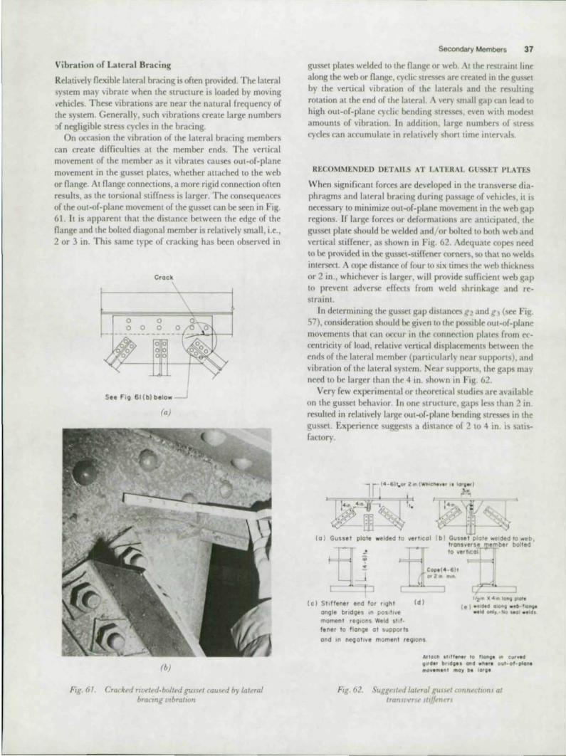
Vibration of Laleral Bracing
Relali,e1y nexible laleral bracing is of len provided. The laleral system may vibrate when the structure is loaded by moving vehicles. These vibrations are near the natural frequency of the system. Generally, such vibrations create large numbers f negligible Slress cycles in Ihe bracing.
On occasion the nbralion of the lateral bracing members can creale difficulties at the member ends. The vertical mO\ement of the member as it vibrates causes out·of·plane movement in the gusset plates, whether auached to the web or nange, At nange connections, a more rigid connection oflcn resuits, as the torsional stiffness is larger. The consequences of Ihe oUl-of-plane mo'ement of Ihe gussel can be seen in Fig. 61. It is apparent Ihal Ihe dislance belween Ihe edge of Ihe nange and Ihe bolted diagonal member is relali,e1y smali, i.e., 2 or 3 in . This same I)'PC of cracking has been observed in
Crack
o 0
o 0 0 01_,~4.Jl.---l o
See FIg 61(b)below ---.1
(a)
(6)
Fuf. (JI. Cra(Red nl't'ted·btlilt'd gUHt'l {'owed by laft'ral bracmg l'lbrallOn
Secondaty Members 37
gusset plates welded to the nan~c: or web. At the r~traint line along the web or nam~e, cydic Str('\l;eS are ('feilled In the ~us~t by the vertical vibration of the laterals and the rr~uhin~ rotation at the end of thr lateral" H.'r) \mall ~ap (an le~ld l() high out-of· plane cyelit bendine; stresses, even with modest amounts of vibration, In addition, lar~e numbers of stress cycles can accumulate 111 relau"e1y short time intef\als.
RECOMMt.NOW Ot.TAILS T LAnKAI (,l' '>St.T PLATES
When significant forces are developed in the Iransvtrse dia· phragms and laleral bracing during passa~e of ,ehicles. il is ne<'ess..1ry to minimize out·of.planr movtment in the web ~ap regions. If large forces or deformallons are anticipatrd, Ihe gussel pi ale shou ld be welded and lor bolted 10 bolh web and verlical stiffener, as shown in FI~ _ 62. Adequate ropes need to be: provided in the gussct·sliITene:r corners, so thal no we:1d~ intcrseel. A rope distance of four 10 six times the "-eb lhitkncs'S or 2 in., whichever is larger. will provide suffitient we:b gap to prevent adverse dfnts from we:ld shrinkage and re:· strain!.
In dClermillill~ the gusset gap dist~lnct'S g] .111d g, (sce Fie;. 57), consideralion should be gi,en {() Ihe pos.ible oUl-of-plane movements thai can o('cur in thl' ronnenion plates from cr· centricity of load, relative vertical displacements between the ends of Ihe laleral member (par{l,"ulariy near supports). and vibration of the lateral sys tem. Near supportS, the gaps may need to be larger than the 4 in . shown in Fi~ , 62.
Very few experimental or theoretical studies are: available on the gusset behavior In one struuure. gaps less than 2 111
resulted in reialiveiy large oUl-of-plane bendin~ stresses in Ihe guS!)Cl. Experience uggests a distanfe of :! to 4 in. is salis· fa<lory .
(a ) Gussel plait welded 10 vertlcOI ( b ) Gusse t plote welded to "'eb , . F ~
• "
( ' "J
tron.veru ember balled 10 ... erllcal
Cop.( 4 · 61t 01' Z", "',"
(c) StIffener end t ar r lghl (d) '2'" x ..... lonq g.IoI,
(e) .. ,414010"9 • • b -IIIIl"ll' .,14 onI,.·,I\Io "al .,td. angle bridges '" poslll ... e
momenl regions 'A'eld 1I1f
tener to f lange 01 supports
and In negative momenl regions
"tlac,. " 111",,, " 110"9' III elllv,d ,lrd,r br,d". CIIId .,.", 0111-0,·,10" ' IM/v, ... , nl 1110, 0, lar"
Fig. 62. Suggl.·\l, d la/aul ,eliOt'! nm/lt't·'wnJ al IrUrl.ll·,'r_\(· ~ItUt'TI~n

38 Bridge Faligue Guide
61012111
FIg. 63. Suggested lataai gusset plait' at pomts wah no tranroerse stiffen"
\"hen the gusset is not attached to the transverse stiffener, a gap distance g. equal 10 3 in. is salisfactory, provided Ihe transverse latera l member is connected to the transverse stiffener and Ihe gussel (see Fig. 62b). This Iype of detail should nOt be used when only diagonal members frame into the gusset. unless reasonable estimates of the displacements can be made and the gap length g. satisfies Eq . ( 12).
If the gusset is attached LO the transverse stiffener, the end gapg" Fig. 57a, must be evaluated as dIscussed earlier under "Summary and Recommendations for Diaphragms and
ross-Frames" and illustrated in Figs. 56 and 62. When the latera l bracing and cross-frames transmit significant outof-plane forces into the girder, as is the case in curved girders, the stiffener shou ld be welded or bolted to the flange. This can be accompli'hed by welding the stiffener directly to Ihe tension flange, as shown in Fig. 62d, or by using a secondary end plate, as illustrated in Fig. 62e. The st iffener can be welded to the plate and the plate in turn only welded along the flange-web weld . This detail has a vcf] favorable orientation when a significant stress gradient exists across the nange. even though its length places it in Category D. Another possibility is to bolt the gusset to the nange. By resisting Ihe lateral forces at the nange. out-of-plane web distortion can be minimized.
When the lateral plate can be allached to the web at points with no vertical stiffeners. as shown in Fig. 63, many of the gap problems can be minimized. This type of connect ion can be used if no significant forces are being transmitted into the girder.
The problem of vibration of the lateral bracing system must also rcCt'ive careful consideration . There are two factors to consider in solving this type of problem. One is to minimize the magnitude of the out-or-plane movement by decreasing Ihe flexibility of the lateral bracing members. This may be
~ C:==!=:E:tf:::;:~,91 :=::J~ I V,b,.".n on I.'ml
r.--
Moderately RIQld Support
~ -.7--69 ---
(c) DIStorttOn In the lateral gusset gap
FIg. 64. SchematIC of VIbratIon dISplacement at lateral gussets
accomplished by increasing the member size or providing an intermediate support. The intermediate support (hanger) forces the member to vibrate in a higher mode and decreases the end movement. The Olher is to minimize the out-or-plane bending stresses al the gusset gap region by making it as flexible as possible. This is illustrated in Fig. 64 . The larger the gusset gap, L , and the thinner the plate thickness, I, the smaller will be the stresses produced by the vibration movement.
Of len Ihe fatigue strength of lateral bracing details is low (i.e., Calegory E) and may influence the main girder design. Also, the lateral bracing system provides a potential for fatigue damage unless properly designed. Lateral bracing shou ld only be used where nece~sar)' . Bracing that is required for erection alone should be remmcd , so that a major source of secondary stress and potential fatl~ue problems can be eliminated.

Miscellaneous Fat~ Considerations 39
CHAPTER 7
MISCELLANEOUS FATIGUE CONSIDERATIONS
In the earlier chapters of this booklet, consideration was gJ\;en to the more mmmonly used bridge ('Onneaions. Thi included their behayior when transmitting primary forctS and the second.ry effects created because ('Omponents of a bridge seldom act independently of each other. In lhis chapter, several miscellaneous fatigue conditions are discussed. ~f ost arc indirectly related to several of the cases discussed previously. Some are ",,'Ondary stress conditions, and others deal with the unusual features of skewed and orthotropic bridges.
DISPLAO.MENT INDUC W SECONDAR V STRESSlS tN OTHER STRUCTURAL SVSTlMS
$e.,eral m,sc.·ell.nrolls cases of displacement-induced secondary st~ a~ rrviewed in this stelion. These include the behavior at cantile\-er noor ~am brackets, trussjoints. and hangers in trusses.
Out-o f· Plane Bend ing in Connection Plates of Ca ntilever Floor Beam Brackets
Girder brid~es art: sometimes constructed with noor beams lhat cantile,er beyond the outside of the longitudinal girders, as shown sc.hematirally in Fig. 65. The tringer system can either be placed on top of the noor beams, as in Fig. 65a, or framed into them, as in Fig. 65b. The perpendicular intersection of the noor beams and main girders makes each member suscrptible to the deformation of the other. 'ince the members arr perpendicular to each other, this results in outof-plane deformalions and higher secondary bending stresses. The ncor beam is subjectrd to this condition when the girder defleas (tOP nange .honens or ICn<llhcns) under live load The stiff slab w,lI not change I<ngth and there will be a relative movement between the slab and the girder. Between expansion joints in the slab, the movement will produce a lateral deneaion of the noor beam, as shown schematically in Fi~. 66. This is especially Critical when the stringers are placed on top of the noor beam, providing a very rigid connection.
A number of bridge structures have experien ed fallgue cracktn~ as a result of the type of deforma,ion shown "hematically '" Fig. 66. 38.39 ThIS has only occurred when the slrin~ers wer~ placed on top of the noor beams. ~ I easurements
of the structural responsr have ronfirmrd that the changrs in curvature of the maIO longitudinal girders under traffir arc responsiblr for ven: large IO-plane bending stre~s in the tic plate conn(,('ung the cantilr\-er bratket to the ncor beam"~ The~ displacement-induced stresses arc often very high in ma~nilude .md can result in visible fatigue dJmage in a short period of time.
(0) Grrder brrd~t" u'lth Ilrl1lgf'rJ 1m Itlp 0/ /100' ~am
J • '.. •• ~
(b) G,rdrr Imd~t" u'uh Itrmgt'Tf frammg mil} jl()(Jr Mom and connt'dwn platt· rm'~ddt'd In j/ab
tlf.:E" .. :-.~ . , . , 9
- • Girder NA
Floor beam
,i.J---I G,rd, r
Strm ..
Sect,on AA
9
In-plane bend", \}
~ :~r~ss and locotlOl'I ~rOCk' (, .. F'9 67)
Pt~ . f}(J Schnnaltf /J/ dt/fmnallfm mlroduud mto floor tKQm~ (antr/el'!'r brarlft'l )/)"el platl' (H't FIg oj)

40 Bridge Fatigue Guide
Fi~urr 67 shows a fatigue crack in a floor beam top flange splice plate, at the girder edge. In this case it is also apparent that the crack has ~ro\\'n from a tack weld . which was made to hold the connection plate to the bracket flange while ri,ets wefe placed. This, of course, is an undesirable condition; tack welds should always be avoided in regions where high cydic stress will octur The A \ VS specification requires that tack welds be properly remoo.:oo or incorporated in the permanent weld Designs should point out areas where no tack welding is permitled . In the example shown, tack welding was not permitted, but did in fact occur. This type of cracking has also developed in plates where no tack welds existed . T he measurements reported in Rer. 38 indicated that the stress amplification would result in eventual cracking at bolted and welded connct'\lons.
J-i(. h7. Fall~f'('radt In cantliel," bracket connf'CtlOn plate
••
FIg. 6R Contllel'l'r bracket lhowmg web connectIOn
Recommended Detai ls for Canti lever Bracket Connection Plates
One way to avoid the type of cracking that h .. o<'Curred m the nange splice plates of cantile\ler brackets is to embtd the floor beam and girder nan~es in the connele slab. ~l easuremenlS
on a number of bridges ha\le demonstrated that no in-plane bending stresses develop in the connection plates ixcause the slab is infinitely stiff in its own plane. Jq li enee, the distortion shown schematica ll y in Fig. 66 rannot develop.
When stringers are plared on top of Ihe floor beams as shown in Fig. 65a, the flange splice plates for the floor beam-cantilever should not be {luached to the main girders. w Releasing this connettion will permitthr structure to deform without introducing undesirable restraint IntO the connection plate. Field measurements have demonstrated that releasing the girder connection is the most efrmivr way to minimize the large in-plane bending stresses. Although this provides a more flexible connection, the bracket web ronncoion to the ~irder must have adequatc nexibility to permit the displacement without de\eloping web crackln~ 10 the bracket and girder As Fig. 68 illustrates, the web connection must pro\lide a large enough gap between its connl"tlion to the girder slirrener and the flange of the cantilever brarket. Generally, coping the bracket flange to dear the mam girder flange will provide adequate "breathing" room .
econdary Bending Stresses in Trus!, Joi nts
Secondary stresses can also be detrimental In truss JOlOts ir weld ends are located at points where cydif stresses o('(:ur This is illustrated schematically in Fi~. 69. A gu<set at an end panel point had a support shoe welded to the gusset plalC. \!though the lower chord is a "zero" stressed member at that point, secondary stresses were developed by bendin~ in the gusset plate. Since the suppon shoe was welded to the ed~e of the gusset plate, the weld end was )()('ated ne-ar th~ stressed r~ion Crack growth occurred in the !(ussct under the cydic «rondary bendin~ stresses.
o 01 1
o 01 1
o 01 r: --------"'r--~ 00 1 0 000
o 01
0 0 0 0 0
End of Weld on Gusset Plo"
rIg. 69. Schema/lc oj cradt UI Kllud "Ia/l' of tnw cauH'd by H'cQru/ar}, l/rt'H

In this cast. thr probkm could br avoidrd by ronnrctin~ the suppon shoe to the end post only. rather than partly welding It to the gusset plate rd~e. Care should br exercised in truss joints to Insun: that wtld ends do not occur allocations of high secondary strtsS<:s. This is also true for tack welds whi h may br used to temporarily hold bolted romponents 10 alignment prior to final bolting. as was shown in Fig. 67 for the cantilever bracke ..
Floor-Ixam-IO-hanger connections in railroad bridges are particularly senslti .. to secondary stress effects. 4O The hanger is both brnt and twisted by the noor bram as it deforms. The degree of brndin~ and twisting also depends on the stringer mnnee-lions to the noor beam. Actual stress mr-3suremenlS ha\'t' indicated that the st~ in the hanger can tx estimated with reasonable 3ccural)' ir a three-dimensional model is usaf and ngld JOintS as umed even at pinned <'Onn«1Ions.41
The AREA Spectfications (An. 1.3.16) require that for truss web members the calculated stress, when Increased by one-third, must meet the fatigue requirements. orne struclUral sySlt'ms may resulL in e\-cn higher increases in the han~er Slress range as a result of the brnding and twisting. Every effort should br made to eSlimate these effects.
SKEWED BRIDGES
As noted when discussing the out-of-plane deformation at noor-bram-to-girder ronnections in Chap"r 5. the out-ofplane movement can bt more severe with skewed bridges. In a skewed bridge, the noor beam not only experiences end rotation as a result of curvature, but also has an increase in end rotation b«au~ of the differenttS in the "ertical mo\emenl at the ends of the noor brams. Any skewed bridge structure using framing members perpendicular to the main girder will experienct some rdative movement between the ends of the tranS"'e~ members.
This means that skewed bridges are much more sensili"e to cracking than ri~ht-angle bridges, because the out-of-pl,,"r movement at the conn~uons are grealer. This is illustrated in Figs. 48 and 53b, where examples of web cracking in two skewed brldges are shown.
The design rcrommendations provided for rlght-angle bridges will not. in general, br adequate for skewed bridge structures. For example. the vertical connection plates at cros ·frames and diaphragms will usually require that the ends of the conne<uon plate br welded to the gtrder nanges. Furthermore. the magnitude of for~ in the cross-frame members will bt largrr, and hence more attention will need to be gi\en to the cross-frame member connections.
Figure -:0 shows a SU~esled diaphragm-girder wnnection for a deck plate gIrder railroad brid~e. It is preferable 10 weld the \'ertiral stiffeners and connection plates to the girder lension flange, rather than attempt to provide large ~aps bttween the end of the ronneCllon plate and the gtrder nange. Depending on the brld~e confi~uration, impraclleallargr gaps would be rrquired to accommodate the differential movrment of adjacent girder.
Miscellaneous Fat.gue ConSlder8110flS 41
Connmions brtween membr,., In ,kewrd brid~ .. , esproall) those connecting members at othrr than rie;ht Jn~lr\, need special auention. ThiS IS particularly true if .. Imple" rnd connections an: planned. Fi~urr 71 a ",hows .t noor-beamto-girdrr conneuion that experirnfed ('ra(klO~ In thr noor bram web. This prohably resulted from erSlr"IOt a, well a' out-of-plane dislOrtion. After the nan~es were spli,rd (see Fig 7tb) so that both weh brnding from the prlmar) fortes and out-of-plane di~tortion Slresses were minimized or riimmate(L satisfactory behavior was obt31nrd
At many skewed bridge mnncrtlOns it appears undeslrablt" to use implc shear ronnenions. TheM' C"CInnrUlOns arr ~n-
r: --, Weld conMcflon plate to top and bottom flang ..
~ .. -=== I~_c -' 0 0: :0 I 0 0: :0 0 o • • 0 0 o· :0 0 0: :0 0 0' '0 0 0: 0 -z , r-~.
L----...J
J
~ Framing Plan
Crock In end floorbeam
=J
ra) Dt/a,1 A a~ buill, ihotl'lnK Jallp(, crtU k locallOn
1
1
Flanljle splice pial" top and bOflom
(I» Dt'lail A lJi modl},,·tJ
Fig. 71 Slt.t'u~d f/ovr beam 10 g.rd,.,.- (umu'cl.on

42 Bridge FaUgoe Guide
siti\'e to OUl-or-plane m \ernent. ~lanv time it is n«'essary to provide bends in the web or connect ing angles that will be e"en more sensiti'vc to both oUl-or-plane movement and restraint. Providing a moment resistant connection, as illustrated in Fig 7 1 b, will minimize the potential problems at such connections. Where cracking has developed at skewed connections. providing restraint to the flange has stopped the cracking and provided a sen'ieeable JOint.
If noor beams are framed into a skewed end noor beam and simple end connections are used, the conncnions must not be sensitive to restraint and out-or-plane distortion. Figure 72 shows one possibility for providing uch a connection. The conne lion plates attached to the end noor beam should be welded to both nanges and the web, so that no out-of-plane rno,cment is introdu~ into the web. Providi ng double plitt plates on each side of the lxam web also mcreases its resistance to out-of-plane movement.
Experience with skewed STeel structures has demonstrated that they are much more prone to significant out.of.plane distortion than right.an~le brid~es. This must be considered when selecting connections ror all components or a skewed bridge, including noor-heam-to-girder and end noor beam connections and secondary members such as cross·rrames, diaphragms, and lateral bradng.
END FLOOR BEAM
t BRIOGE
~G PLAN
t. END FLOOR BEAM A
r- t fLOOR BEAM
DETAIL "A"
"CONN It
SECTION A- A
fig. 72. Suggel/ed "umple" co"n~clJOn at jk~wed end floor beam
DRTItOTROPtC STUL DECKS
Care must be exercised in the design of onhOlropic stetl bridge decks because the frequency of loading and the proportion of stress due to live load is very high . tany details will be subjected to more than one stress cycle per truck, as each axle (or wheel) may cause a stress cycle.
Obviously, low fa tigue strength details should be avoided. For example, splice plates which fall Into ategory E would decrease the fatigue resistance of deck stiffeners substantially. ~teasurements on an orthotropic bridge deck have indicated that cracking is probable after 20 to 40 X 106 variable stress rycles42 with Category E details.
Work in England43 on experimcmal orthotropic bridge panels and the field studies reported in Ref. 44 have demonst rated that high cyclic stresses occur in the deck transver~ to the stiffeners. When stiffeners are attached to the nange plate. the longitudinal welds are often partial-penetration welds and available studies indicate thai Category C is probably applicable, considering the stress range at the weld root 4 2.43 In any evcnt, the stiffener should be welded directly to the plate, as illustrated in Fig. 73a. The weld throat should provide at least 80% of the sliffener plate thickness, in order 10 minimize the notch effect at the weld rool.
One should avoid the use of a nanged stiffener as shown in Fig. 73b. This results in a much more severe stress condition at the weld root as the deck plate deforms. The stiffener nange provides a more severe "effective crack length" at the weld root and this enhances the fatigue crack propagalion.
(a) Ruomm~nded Jil/fi:ner-flarlgt ronnectwn
l - -. -r 11
(6) Al.101d bendmg Jtlbl"Tler top to form flange
Fig. 73. At/achmg J/lf/enerJ 10 deck plate

Another important connection in orthotropic steel decks is between the stiffener and the noor beam. The stiffener should not be interrupted at the web of the noor beam by a welded joint placed at theend of the stiffener. It is preferablefor the stiffener to run continuously through an opening in the noor beam without a break. This also permits the stress range to be more effectively controlled, as the critical point is the weld to< termination at the end of the weld auaching the stiffener to the web. By reducing the weld length, a significant reduction in the bending stresses In the trapezoidal stiffener will occur. Figure 74b shows the preferred means of connecting the sllffener to the noor beam. This connection also permits 'he noor beam web to ne. more readily.
Ex~riente on an experimental orthotropic deck panel, which had trapezoidal stiffening ribs framing into the noor beams without a cutout (Fig. 74a), demonstrated that premature fallgue was possible in the load carrying welds which ronnwffl the stiffener 10 the floor btam ",eb.o ,"'"
plices of the orthotropic deck panels can be made by high-strength bolts and welding. Sometimes a combination of these methods is used, such as welding the deck plate and bolting the ribs and noor beams·'·46 Under the local wheel load r"'ponse, the welded jomt is near the neutral axis of the deck and is subjected to lower cyclic stress.
Figure 75a shows the field deck splices used for the POrt
Mann Bridge." lIigh-S1ren~th rivctcdjoints provided a good fatigue strength detail IIlgh-strength bolted joints would provide an ('vcn better splitt. A combination joint is shown in Fig. 75b. A, noted above, it places the groove welded splice near the ncutral axis for local bending of the orthotropic deck. Hence. a good fatigue strength detail is provided for both deck plate and stiffening ribs.
+ +
11 1 I J
r
(b) Sitl/en" ConIInUf)UJ thmul!h rutout In f/(~r /worn u"t'h IS pr~f(Tabir
I
Miscellaneous Fatigue Considerations 43
WlLD REQU IREMENTS AND SPECIAL CONSIDERATIO S
Groove Welded Splices
It has bttn common practict for many years to require thr nondestructive inspection of groove welded nan~e 'pi ices. Both the MSIITO and AREA specifications have reqUIred testing of groove welds in main members (see AA I-ITO Standard
fH'oJicatlons/or Il'ddm~ nfStrudllral Slt"d III~h a} Bndt:" (1975) and Art . 3.5.5 of the "REA Specifications) .
The >;'1me degree of quality has not been Imposed on many groove welded components that are attached to bnd~e girders. &V'eral bridge gIrders hale experienced faugue crack intll.tion and growth because the groo\'r welds used to splice longIlu· dinal stiffeners had inromplrt(' pt'ne-tration .47 in('e- thr Ion· gilUdinal stiffener was conside-rrd an attachment, no wdd quality criteria were established and no nonde-structiv'(, test reqUIrement were imposed on the lonl(itudinal tiffener welds. even though the welded spltre W3\ perpendicular to the primar)' bendmg stress. Srleral of th<Se splices existed along the girder length, and in st\eral inst~1nn· they existl'd in posItive moment regions for drchiteClural purposes. The: iargr naws permitted crack growth to occur at lery low levels of (,lIrulated tre. ran~e (about 1 ksi and abme) making fraflure of the
girder inrvitable, ..\ more dNailed discussion of one of the structurrs IS gl\rn in Ref 47
This incident illustrates that we-Ided butt splitt's m ('ton· dar) material sub,teetrd to main mrmber St~ses must be- madr in accordance with the requirements for splices m thr mam material .
A related type of behavior w," ol"" .... ed 10 ~roole weld, that ronne<1ro lateral gusset plates 10 trans\ eNt sliffrners.11 I n this detail a backup bar Iva, used 10 make a ~roole weld perpendirular to the bendm~ stres< field . Lark of fusion 10 this transvrr'>t groove weld resuitr-d in fati~ur crack ~rowth III
those areas,
ra)
'J
Du ll spbu ( Purl " tann Bndgd
rr • G
. " " " .. .
(b) Go mbmatmn spill r u",h g""d fa/II!U~ rt'w lan l"
fig. 75. Drek pa",{ Ipl","

44 Bridge Fatigue Guode
BoCkup Bors
Transverse Stiffener
Loterol Gusset
Potential Lock of Fusion Area
Fig. 76. SchematIc of taclt-of-funon OTta when baclcup bar IS
perpendIcular to Slress field
The history of crack inilialion and growlh in Ihe laleral gussel plale, and Ihe propagalion 10 failure of the girder to which it was attached, also illustrate a related problem to which designers should be continuou Iy alert. The facI Ihat the gusset plate transverse groove weld was detailed to come into contact with the girder web provided a path into the girder which eventua lly destroyed the cross section. This can be prevented by providing interruplions in potential crack paths when attachments are connec-ed to main girders. For example, adequate cope holes bet weer the transverse groove weld and Ihe girder web, as shown in Ihe gusset plate in Fig. 57, would prevent a fatigue crack in the transverse welded gusset plate from growing into the girder web.
This failure also dernonSlraled Ihal it IS undesirable to leave backup bars in place when Ihey are perpendicular 10 Ihe applied stress field. As illustraled schematically in Fig. 76, Ihis can result in a crack-like defect perpendicular to the stress field . No nondestructive testing process can con istently detect lack of fusion . Any lack of fusion in Ihe weld makes Ihe condition very critical.
Transition Radii
When nanges of different widlhs have been spliced, il has been the practice to use a transition radius or straight tapered transition. Criteria for the transition radius are given in Art. 1.7. I 5 of Ihe AAS IITO Specifications.
Backup bar splict must bt fu ll penetration butt weld
Grind flush before ottochinv to pIote ";th lonQitudinol
Fig. 77. Schematic showmg bUll splice In bacJClng bar
The 1977 AASHTO and AREA specifications permit groove welded and fillet welded attachments with various transition radii . Large radii permit a more favorable stress category. (See Fig. 1.7.2, Example 14 , AASHTO Specifications, and Fig. 1.3.13, Example 19, AREA Specificalions.)
Care must be exercised when a transition, whether radiused or straight tapered, is used to improve fatigue strength. The specificalions require Ihal Ihe weld end be ground smoolh. Every dfon must be made to insure a smooth transition, with no rejectable weld imperfections. Recent testS have indicated that rejectable weld discontinuilies, such as slag inclusion or large ga pockets. must not be apparent in the ground tran~ silion radius. Care should also be taken wilh the rOOl pass of longiludinal groove welds which conncel radiused details 10
a flange. These can also lead to crack initiation sites if a smooth weld is not made.
When permanent backup bars are essentially parallel to the direction of applied stress, they must be cont inuous. AIIhough backup bars are not usually counted upon 10 resist Ihe loads, they are in fact subjected to the same stress range as the S1ressed elements of the section. Therefore, a welded bUll splice in the backup bar muSl be a fu ll-penetration bUll weld which is made prior to allaching Ihe backup bar to the member elements as illustrated in Fig. 77. Any lack of fusion Ihat is parallel to Ihe direction of applied stress has no effect on the fatigue resistance.

Relerences 45
APPENDIX A REFERENCES
1. Fisher, J W. Classification of Typical Welded Bridge Details for Fatigue loading Research Results Digest No. 59, Transportation Research Board. 1974.
2 Fisher. J W .. K H. Frank. M. A. Hirt. and 8 . M McNamee Effect of Weldments 00 the Fatigue Strength of Steel Beams NCHIP Report
102. Highway Research Board. 1970. 3. MunS6. W. H. and J . H. StalfmeytJr Fatigue In We'ded Beams and
Girders Highway Research Board Bulletin 315, 1962. 4 ASCE SWcommittee 00 W_ CoYm--Ptated Beams Commentary
on Wetded Cover-Plated Beams ,Jotrnal of the Structural Division.
ASCE. Vol. 93. No. STA. Aug. f967 5 Watkll1SOO. F., P H. Elodg«, and J. 0 Hamson The Fatigue Strength
of Welded Joints and Methods lor its Improvement Proceedings. Fatigue of Welded Structures Conference, The Weldmg Institute, England, Paper No. 7, Vol. I , 1971.
6 Fisher, J. W. and I M. Viest Fatigue Ule 01 Bridge Beams Subjected to Control~ Truck Traffic Preliminary Publication. 7th Congress. IA8SE, pp. 497- 510, 1964.
7. Bowers, D. G. Loading HistO!')' Span No. 10 Vellow Mill Pond Bridge 1-95. Bridgeport. Connecticut Research Project NPR 175-332.
Dopart~ 01 Transporlation, COOn .. May 1972. (See also Hi!jlway Research Record 428. Highway Research Board. 1973.)
8 Founlain, R. 5 , W. H. Moose. and R. D. Sunb<Iy Specifications and Destgn Relations Jocxnal of the Structural DiVISion. ASCE. Vol. 94. No STl2, Doc. 1968.
9. WRC Committee for Fatigue Testing Calculation and Graphical
Representation of the Fatl!}Je Strength of Structll8l ..Joints Welding Journal ReS6arch Supplement. Vol 21. No. 2. 1942.
10. Fisher. J. W .• P. A. Albrecht, B. T Yen. D. J. Klingerman. and B. M McNamee Fatigue Strength of Steel Beams. With Transverse StoffOflefS and AttacIvnonts NCIflP Report 147, H'iflway_ Board. 1974.
11. Yen, 8. T .• N. ItA Marchica. andJ. W. Fisher Stress Measurements and Behavior of the Lehigh Canal Brldge Fritz Engineering laboratory Report 386. t, Lehigh University, Dec. 1973.
12 Miner, M. A. Cumulatiye Damage In Fatigue Journal of Applied Mechanics, Vol 12. Sept. 1945.
13 Cudney. G. R The Effects 01 Loading on Bridge life Highway Re
search Record No. 253. Highway Research Board. 1968. 14 Galambos. C. F and C. P. Heins loading History of Highway
Bridges. Comparison of Stress Range Histograms Highway Research Record No. 354, Highway Research Board. 197'.
15 Munse. W. H aOOL. H. G"overFa1igue of Welded Steel Struch.res
Weldmg Research Council. New York. 1964
16 GtKney, T. R. Fattgue of Welded Structures cambridge University Press. , 968.
17 Signes. E. G .• R G. Baket'. J . D. Harrison. andF. M Bt.rdei(inFactors Atloct'ng the Fatigue Strength of Welded High Strength Stools British WekJmg Journal. Vol. 14, March 1967.
18 Harrison. J. D .• F M. Burdekin, and J . G. Young A Proposed Acceptance Standard for Weld Defects Based Upon Suitability for
Service Proceedings. Second Conference. The Significance of Defects in Welds. The WekJmg Institure. 1969
19. Basler, K. and B Thurlimann Plate Girder Research National En· gineering Conference Proceedings, AISC. 1959
20. Schillmg. C. G , K. H. K/lppstein. J. ItA aarsom. and G T Blake Fatig.oo ot Welded Steel Bridge Mofrbors L\ldor Variabl&-Amplotudo loadings ReS6srch Results Digest 60. NCHRP, TransportatIOn Research Board. 1974
21 . Schilling. C. G . K H. KI'ppstem. J. M. aarsom. and G T Blake Fatig.oo ot Welded Steel Bridge MorrOors L\ldor Variabl&-AmphtOOo loadings Final Report. NCI#lP Project 12- 12. TransportatlOfl Research Board. Aug. 1975
22 . Rolfe. S. T .• and J M. aarsom Fracture and Fatigue Control In Structures- Applications of Fracture Mechanics PrentiCe-Hail. Inc .. Englewood Cliffs. N J . t977
23. Barsom. J. M. Development of the AASHTO Fracture-Toughness Requirements for Bridge Steels Journal of Engineering Fracture Mechanics. 7. 1975. p . 605 (Also available fromAISI. 1000 16th St .• Washington, D.C.)
24 . Boyer. K D .• J . W Fisher, G R. Irwin. G V Krishna. U Mort. R Roberts, and R. E. Slockbower DetermU18tKHl of Tolerable FlawSizes in Full Size We'ded Bridge Details Fritz Englneermg laboratory Repon No 399-3(761, Doc. 1976.
25 . Slockbo_, R E. and J. W Fis/Jet'Fatog.JO _stanco of Full Scale Cover-plated Beams Fritz Eng1neermg Laboratory Reporl No 386-9{771, March 1977
26 Moses, F M .• G G Goble and A . Pavia Truck loading Model lor Bridge Fatigue Specialty Conference on Metal Bridges ASCE. 51 Louis, Mo .. Nov 1974
27 . Johnston, 8 . G. and E. H Mount Flexible Welded Angle Connect"",s
Weld'ng Journal, Vol 19, No 10, 1940 28. Lewlft. C. W .• E. Chesson. and W H Munse Restraint Char9cler~
istics of Flexible Riveted and Bolted Beam--to-CollXlYl Conoectoos Engineering Expeflmenral StatIOn Bulletin 500. University of illinois. 1969.
29. Wilson, W. and J V. Coombe Fatigue Tests of Connecllon Angles Engineering Experimental Station Bulletin 317. Vol 37. No. 6, University of IfIlIlo/s. Oct 1939
30. Wilson. W. DeSign of Connection Angles lor Stnngers of Railway Bridges Proceedings. AREA. Vol. 4 I. 1940.
31 . Manual for Railway Engineering Chapter 15, Steel Structures. American RaJlway Engm8enng Association. 1976
32. Specification for StnJCtu'"al..Joints Using ASTM A325 or A490 Bolts 10th Edition. Feb. 4. 1976. R8S8arch Council on Riveted and Boned Structural Joints
33 . Yen , B. T. and J A Mueller Fatigue Tests of Large-Size Welded Plate Girders WRC Bulletin No , 18. Dec. 1966
34 . Lew. H W and A A. Toprac Fatigue Strength of Hybrid Plate
Girders Under Constant Moment Highway Research Record No. 167, 1967.
35. Vincent. G. S. Tentative Criteria for load Factor Design of Steel Highway Bridges AISI &Ilel,n No. IS, March 1969

46 Bridge Fatigue Guide
36 . PaNerson. P. J .. J. A. Corrado, J. S. Huang, and B. T. Yen Fatigue and Static Tests of Two Welded Plate Girders WRC Bulletin No.
'55, Oct. '970. 37 . Fisher, J . w.. A. W. Pense. and R. Roberls Evaluation of Fracture
of Lafayette Street Bridge Jotxnal of the Structural Division, ASCE. Vol. 103, No. ST7, July '977.
38. Fisher. J. W.o B. T. Yen. and J . H. Daniels Fatigue Damage in the lehigh Canal Bridge from Displacement Induced Secondary Stresses Transportation Research Record 607. TRB, 1977.
39 . Yen , B. T., N. V. Marchica. A. L. Coates. and J. W. Fisher Studies on Bridges with Cantilever Brackets Fritz Engineering Laboratory
Repor1386.3, April '977. 40. Field Investigation of Two Truss Spans on the Southern Pacific
Company. Report ER-82. Association of American Railways,
Chicago, III" May '968. 41 . Fisher, J . W. and J. H. Daniels An In\lestigation of the Estimated
Fatigue in Members of the 380-ft . Main Span, Fraser River Bridge AREA Bulletin 658, Proceedmgs Vol. 77. JUIl8-..July 1976.
42 . Daniels, J. H., B. T. Yen, and J. W. Fisher Stresses in Orthotropic Deck of Rio-Niteroi Bridge Under Traffic Transportation Research
Record 607, me, '977. 43. Nunn, D. E. An Investigation into the Fatigue of Welds in an Ex
perimental Orthotropic Bridge Deck Panel Department of the Environment, TRRL Report LR629, Crowthorne. England. 1974.
44 . Nunn, D. E. and S. A. H. Morris Trials of Experimental Orthotropic Bridge Deck Panels Under Traffic Loading Department of the Environment. TRRL Report LR627, Crowthorne. England. 1974.
45. Troitsky. M. S. Orthotroplc Bridges Theory and Design The James F. Lincoln Arc Welding Foundation. Cleveland. Ohio. 1967.
46. Design Manual 'or Orthotropic Steel Plate Deck Bridges American Institute of Steel Construction, New York. N. Y .• '963.
47 . Fisher, J. W., M. D. Sullivan. and A. W. Pense Improving Fatigue Strength and Repairing Fatigue Damage NCHRP Report 12-15,
'977. 48. 1977 Interim Specifications, Bridges American Association of State
Highway and Transportation Officials, Washington, D.C.

AASHTO and AREA Fatigue ~1IiC8tlons 47
APPENDIX B
AASHTO AND AREA FATIGUE SPECIFICATIONS
Artielt 1.7.2 of tht 1977 AASHTO Specifications, and Arts. 1.3.13 and 2.3.1 of the 1977 AREA Specifications (with Commtntary) art rtproduttd in full in this Appendix. Thty contain tht following major changtS:
(a) Full us< of tht livt load and impact strtSS rangt conctpt, insttad of tht maximum allowablt strtss bastd on strtSS ratio, R I and t~nsile strength of steel.
(b) Mattrial subjecttd to fluctuating comprtSSion strtSStS was exempted from fatigue requirements.
(c) Us< of six basic dtSign strtSS rangt cattgoritS in Tablt 1.7.2AI of tht AASHTO Specifications and Tablt 1.3.13B of tht AREA Specifications.
(d) Rtarrangement of Table 1.7 .2B, StrtSS Cyclts, of tht AA HTO Specifications to provide for structurts subjecttd to extrtme truck traffic volumt and for stparale transverse member requirements. Development of Tablt 1.3.13A of tht AREA Specifications to aocount for strtSS eyelts depending on span Itngth , type of member, and frequency of trains.
(t) Inelusion of Tables 1.7.2A2 and Fig. 1.7.2 in tht AASHTO Specifications and Tablt 1.3.13C and Fig. 1.3.13 in tht AREA Specifications to illustralt tht scope and applicability of tach cattgory and dttail classification.
AASHTO SPECIFICATIONS-BRIDGES (1977) ARTICLE 1.7.2 REPETITIVE LOADING AND TOUGHNESS
CONSIDERATIONS
(A) Allowable Fatigut Stress
Members and fasteners subject to repeated variations or rrvtrsals of strtss shall bt designtd so that tht maximum strtSS dOtS not tXcttd tht basic allowablt strtSsts given in Artielts 1.7.1 and 1.7.4.1 (B) and that the actual range of strtSS dots not excttd the allowable fatigue stress range given in Table 1.7.2A I for tht appropriatt type and location of mattrial shown in Tablt 1.7.2A2 and illustrattd in Fig. 1.7.2.
Main load carrying mtmbtr compontnts subjecttd to Itnsilt strtSses which may bt considtrtd nonrtdundant load path membtrs that is, where failurt of a singlt dtmtnt could caust collapst shall bt designed for tht allowable stress rangts indicated to Tablt 1.7.2AI for Nonredundant Load Path Structures,
Tht rangt of stress is defintd as tht algtbraic difftrenct between the maximum suus and the minimum stress. Tension stress is considtrtd to havt tht oppositt algtbraic sign from compr~sion stress.
In Table 1.7.2A2, "T" signifitS range in Itnsile strtSS only; "Rev." signifies a range of st~ss involving both tension and compression during a stress cycle.
(B) Load Cycles
The numbtr of eyeitS of maximum strtSs range to bt considtrtd in tht design shall bt s<lecttd from Table 1.7.28 unltSs traffic and loadometer surveys or other considerations indicate otherwise.
Allowable fatigue stresses shall apply to those Group Loadings that inelude livt load or wind load.
The numbtr of cyeles of stress rangt to bt considertd for wind loads in combination with dead loads, except for struc~ tures where other considerations indicate a substantially different numbtr of eyeltS, shall bt 100,000 eyeles.
(C) Charpy V-Notch Impact Requirements
Main load carrying membtr compontnts subjecttd to ttnsilt stress requirt supplemental impact propenies as dtSCribtd in the Material Specifications.
These impact requirtmtnts vary depending on the type of sted, type of construction, wdded or mechanically fastened , and the average minimum service temperature to which the structurt may bt subjecttd. ' Table 1.7.2C contains the temperature zone designations.
Components rtquiring mandatory impact properties shall bt dtsignattd on tht drawings and tht appropriatt zont shall be designated in the contract documents.
A514 sttel shall bt supplitd to Zone 2 rtquirtmtnts as a minimum.
Main load carrying mtmbtr compontnts subjecttd to tensile stresses which may be considered nonredundant that is, where failure of a singlt tlemtnt could cause colla pst- shall bt designtd for tht allowablt strtSS rangtS indicattd in Tablt 1.7.2Al for nonredundant structures.
I The hons and philosophy used to de~/op these requ rrnnmts are gwen m a paper enlltled uThe Development of AASIITO Fracture-Toughness ReqUIrements For Bndge Steels" by John M . Bar-10 m , fe bruary }975, avaIlable from the Amen can Iron and Stul Institute, Washmgton, D.C.

48 Bridge Fallgue Guide
Tabk I. 7 .2A 1
REDUNDANT LOAD PATH STRUCTURES'
Allowable Ranse of Stress. F3,
Category Fo' For Fo' For OVC'T
{SeC' Tablt 100,000 500,000 2,000,000 2,000,000 1.7.2A2)
I-Cydes Cycles Cyclcs Cycles
ksi MPa ksi \1Pa ksi MP. ksi MPa
A 60 4 15.69 56 248.21 24 165.47 24 165.47 -I--
8 45 310.26 27.5 189.60 18 124.10 16 110.51 -C 52 220.63 19 13 1.00 15 89.65 10 68.95
12' 82.74'"
D 27 186.16 16 110.31 10 68.95 7 48.26
E 21 144.79 12.5 86.18 8 55.15 5 34.47
F 15 105.42 12 82.74 9 62.05 8 55.15
NONREDUNDANT LOAD PATJI STRUCTURES'
A 56 248.21 24 165.47 24 165.47 24 165.47
B 27 .5 189.60 18 124.10 16 I IO.S! 16 II O.S!
C 19 is 1.00 13 89.63 10 68.95 9 62.05 12' 82.74· II' 75.84·
D 16 110.3 1 10 68.95 7 48.26 5 34.47
E 12.5 86.18 8 55. 15 5 34.47 2.5 17.24
F 12 82.74 9 62.05 8 55. 15 7 48.26
• For transverse stiffener welds on girder webs or n"nges. IStrucluTe types wilh multi-load paths where a sinliil1e fracture in a member cannot lead to the collapse. For example, a simply supported single span multi-beam bridge or a multi-clement C'\ e bar truss member have redundant load paths.
lStrucluTe types with a sin~ l c oad path when: a single fracture can lead to a catastrophic collapse. For example, nam~e and web plal~ in one or two girder brid1r;cs. main one-clement tNS manbers, han~er plates, caps at sin~le or two column bents have nonredundant load paths.
Table 1 72A2 - r-Stress Il lustrative
Category Example No. General Kind of (See Table (Sec fig.
Conditio n Si tuat ion Stress l.7.2A I ) I. 7.2) ---Plain matt'flill Ba~ metal with rolled or cleaned surfaces. J-lame cut T or Rev. A 1,2
edges with ANSI smoothness or 1.000 or less
Built ·up members Boue metal and weld metal in members without at· T or Rev. 8 3,4,5,7 t.lchments. bUIIt·up of plates or shapes connected by continuous full or partial penetration ~roove welds or by continuous fillet welds parallel to the direct ion of applied stress
Calculated flexural stress at toe of tr • .msver~ stiffen· T or Rev. C 6 er welds on girder webs or nanges
Base metal at end or partial length welded cO\er plates T or Rev. E 7 ha\'in~ squart' or tapered ends. with or without "dds across the ends
- I-Croove wdds Base metal and weld metal at full penetration groove T or Rev. B 8,10, 14
"dded splices of rolled and welded sections hay· ing simi lar profiles when welds arc ground flush and weld soundness established by nondestructive inspection
Icont'd nrxt pGgr)

AASHTO and AREA Fatigue Specilications 49
Table 1.7.2A2 (cont'd) -
Stress 11Iustr.IIVC' Catc:gory Exampk ;.lu,
General Kind of (!ke Table (See hit. Condition Situation Strns L1.2AI) L1.2) --Groove welds Base metal and weld metal In or adjacent to full Tor Re .... 8 II, 12
(cont'd) ~nelration !{roove wt'lded splices at transitions in width or thicknell, with welds ground to provide slopes no steeper than I to 2\0'.1, with grinding in the direction of applied nrc:oss, and weld sound-ness established by nondestructive inspection
Ba~ metal and weld metal In or adja«nt to fun T or Rev. 8,10,11, 12. 14 pc:oNration groove welded splices, with or without transitions having slopes no greater than 1 to 2~, when reinforcement is no t removed and weld soundness is established by nondestructive inspection
Base m~tal at d~tails attach~d by groov~ w~lds sub- T or R~v. D 15 j~ct to longitudinal loading wh~n the detail I~ngth L. paralkl to th~ line of strc". is bc.'twctn 2 in. (50.8 mm) and 12 IIm~s th~ platc thickn~ss. but less than 4 in. (101.6 mm)
-. Base: m~tal at details attachcd by grOO\lc welds sub· Tor Rcv. E I~
j~ct to longitudinalloadmg whcn the d~tail length L, greater than 12 limes thc platc thickncss or greatcr than 4 in. (101.6 mm)
BaS<' mctal at details attached by groove welds sub· jected to transversc .tOd/or longitudinal loading rcgardless of detail kngth when weld soundn~ss transvcrse to thc direction of strcss is established by nond~stru tivc inspection (a) When pro\'ided with transition radius ~qual to T or Rev. S 14
or grcater than 24 in. (0.610 m) and weld end ground smooth
(b) When provided with transition radius less T o r Rev. C Ii than 24 to (0.610 m) but not less than 6 in (0. 152 m) and weld end ground smooth
(e) When provided with tranSition ~diu, less T or R~v. D 14 than 6 in. (0.152 m) but not It'ss than 2 in. (0.051 m) and weld end grou nd smooth
(d) Wh~n provided with transition radius between T or Rev. E I' o in. and 2 in. (O and 0.051 m) - , ---
Fillt' t welded Base: metal at int~rmittent fill~t welds T or R~v. E conncctions
Base metal adjacent to fillet welded attachments Tor R~. C I~, 15, 16, 17 with length L in dlr~ction of stress less than 2 in. (50.8 mm) .U1d stud-1YP~ §h~ar connectors
- I-Sase metal at dctails altach~d by rillet welds with T o r R~v. D 15, 15, 16
detail length L in direction of stress between 2 in. (50.8 mm) and 12 times the plate thicitness but less than 4 in. (101.6 mm)
Base m~tal at allachm~nt detoliis with d~taillength T or Rev. E 7,9, IS, 16 Lin dlTectioo of stress (length of fill~t weld) gruttT than 12 timu the platc thickncss or grUtu than 4 in. (101.6 mm)
B~ mual a\ details 'attached by fiUr:\ wdds r~z.lot"d-less of length in dirrctlon of slrrss (shcar strrss on the throat of fillet w~lds govrrn~d by SlrC'ss catC'gory F): (a) When provided with transition radius rqual T or Rcv. S 14
to or gre&tler than 24 in. (0.6 10 m) and wdd rnd 1V0und smooth
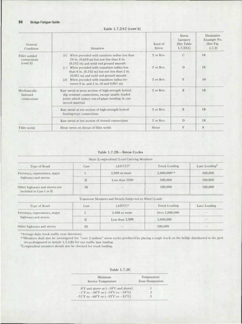
50 Bridge Fatigue Guide
Table 1. 7.2 \ 2 (co nt 'd)
Stress Category
Kind of (Se< Tabl e C~n('r.&1
Condition Situation Strc$5 1.1.2A I)
hllN wdded <:onneclions (cont'd)
\tnhamully fastcned connections
Fillet welds
s than (b) When pro\ided with tiln ilion radius les 24 in. (0.610 m) bU(Jlot kn than 6111.
(0.152 m) and weld rood ground smooth (c) When provided with transition radiUS Ie
than 6 m . (0.152 m) but not less than 2 (0.051 m) and weld end ground smooth
(d) When pro\,jded with Ir.msilion radius be
on.
{",un 0 in. ;and 2 in. (0 and 0.051 m)
hed But" metal at gros Kellon of high-strength bo slip resistant connections, U~pl axially load joints which induct' out-of-plane bendmg In
<d con-
neeted material
B..LSC metal at net ('Clion of high ·st rength b o lt bearing-typt' connection
<d
B.tsc metal at net s<:clion of rjvC'ted connection s
Shear stress on throat of fillet welds ----~- -----
Table 1.7 .2B SLress Cycles
T or Rev.
T or Rev.
Tor Rcv.
Tor Rcv.
T or Rev.
T or Rev.
Shear
'bin (Lon~itudIll.JI) Lo.ad Cotrrying ~tcmbcrs
Type of Ro.ad
t 'ret'wa.)"s. t'xprcss\\otys, m.i.Jor
hll~h\O;.tY' and SIrt'clS
Otllt'r hl'th\\.t)", .lIld tree" not induded m (:;15(, I or II
II
III
(.J DlT)' Truck LOdding
2,500 or more 2,000.000 ------1-----
Lt'SJi than 2500 500,000
100,000
Tran5\o'crsc: Members and Detail> Subje~lcd to \\h~1 Loads
-------r------~- ------T)'pe.' of Ro;,ul
rrt'l"ways. t'xprcssw.lys, maJor
highwot)'! .lfId strcelS
Othcr hlghwJ)'s Jnd str('cts
"A\lcraj{(' d;ul)" lruc..k tra(fi~ (Ole dircctlon).
au<
II
III
(.10111
2.500 or morc
Less than 2.500
Truck Loadm!.;
Over 2,000,000
2,000,000
500,000
C
D
E
8
8
D
~
lIIustrJtivc Example ~o.
(SC( Fig. 1.7.2)
14
14
14
18
18
18
9 ---
1...&11t' Loadin'tt
500,000
100,000 ---
100,000
I_me Loadin~
··\lC'mbC"f shotll .. bo bt' 1O\oC'StigalC'd for "ovcr 2 1111lllon" strcss cycles produc('d b)' placing.l slngl(' truck on (he bridli\:C' distributed 10 the gird' US oJ dtjlf{Iwt'd m \rlldc 1.3.1(B) (or One lraf(jc I.HIe Joadin't.
tCongltudmal membcn should also be chec..ked for tTU(k loadmg.
Table 1.7.2C
~hnlmum
Service [cmperatun:
o t imd abO\ot' or ( ISDC and abo\oe) 1 I' to 30D I- or ( IgOC to 34°C)
. .31'1-(0 60°Joor{- 'SOCia 51 0q
Temperaturc Zone Oesi~n.:ttion
I 2 l

AASHTO and AREA F8Ioguo Specllocaloons 51
- c l-
eI j) 2
c / ~
~ )
10
2' (0610 m) Rod II - E ~-A 514 and A 517 --,
:3
C:;~i~) Dlop~ Gusset 6
c Category 8
SQuared End I Tapered or W,der than Flange
Cote Or 8
Ca tegory e: -7
)
12
13
- Cat.gory C " •
WELD CONOtTION · T UneQuoi Ttucknns· R,1f'I In PkK. E Unequal Thlcw •• - Rt"" RtlNMd 0 EQI,IOI Thtckness-R,..., ItI Ptoce C
/'\-:&~~, __ !E~:' T:""~';;"'~"~-;;;R'"' RemoYed B - • For transvers. IOodrIQ· cneCk
"
15
16
IrOl'lSll1On radIUs for pon_tIIe Iow. r COltQOty
R~24 (oom) B 24"(6K>ml>R> 6"1I~2ml C 6"II!IZ m»R> 2"( 05lml 0 2"(05Iml>R E •• Also ~. 10 tronsvefM .......
8
.... J-cJ::::7==J~-,Co tegOry e: Ca tegory F (I (on bose metal) n wall'
F==~~~~~~,c~o~tegory e: _ _ , (, n bO.:...,:ato/)
- -t==r.~~ \ () () -() () -9 18
• AI End of Weld. Has No Length
FIg. I 7.2. Il/uslra(we e)(amp/~J

52 Bridge Fatigue Guide
AREA SPECIFICATIONS FOR STEEL RAILWAY BRIDGES' (t977)
1.3.13 Fatigue
(a) Members and connections subjected to repeated nuctuations of stress shall meet the fatigue requirements of paragraphs (c), (d), (e), and (r), as well as the strength re
quirements of Section 1.4 or 2.4.
(b) The major factors governing fatigue strength are the
number of stress cycles, the magnitude of the stress range, and the type and location of constructional detail.
(c) The number of stress cycles, N, to be considered shall be selected from Table 1.3.13A, unless traffic surveys or other considerations indicate otherwise. The selection depends on the span length in the case of longitudinal members) and on the number of tracks in the case of floorbeams and hangers,
(d) The stress range , SR, is defined as the algebraic difference between the maximum and mjnimum calculated stress due to dead load, live load, tmpact , and centrifugal force. If live load, impact, and centrifugal force result in compressive stresses and the dead load is compression, fatigue need not be considered .
(e) The type and location of the various construct ional deta ils are ca tegorized in Table 1.3. 13C and illustrated in Fig. 1.3.13.
(r) The stress range shall not exceed the a llowable fatigue
stress range, SR/al' listed in Table 1.3. 138.
• Tak.en from Chapter 15, Steel Structures, of the American Railway Engmeenng AssOctollon Manual for ROIlway Engmeenng (";xed Properlles) of 1976.
Table 1.3. 13 A
Member Description
Span Length, L. of Flexural
~lembe r or Truss
L > 100'
100' ;. L > 75'
Constant· Stress
Cycles, N
150,000
200,000 Classificat ion I
Longitudinal flexural members .tnd their connections: or f-------+------
75' ;;. 1. > 50' 500,000 truss chord members. includ- f--------+-----in~ end posts, and their con· nections
Classification II Truss web members and their
connections except as listed In Classification III
ClassifiaHion IH Floorbeams dnd their connec
tions; or truss hanRcrs and sub·diagonals, which carry f100rbeam reactions only, and their connections
50' ;. L > 3D'
30' ;. L
Two tracks lOAded
One track loaded
Two uitck'i loaded
One track loaded
2.000,000
> 2.000,000
200,000
500,000
500,000
> 2.000,000
Note: Tables 1.3.1SA and B are based on bridges designed for E80 loading. For the procedure to be used for J. design loading other than E80, sec the Commentary, Art. 9.1.3.13, Step 5.
2.3.1 Fatigue
(a) Members and connections subjected to repeated nuctuations of stress shaJ l meet the fatigue requirements of Article 1.3. 13.
AREA COMMENTARY
9.1.3.13 and 9.2.3.1 Fatigue
Members subjected to repeated applications of load under
certain conditions will fail at a lower unit stress than they would under a single application of load. Such failures are
commonly referred to as fatigue failures. All editions of these specifications between 1910 and 1969, inclusive, have required that members subject to reversal of stress (whether axial, bending or shearing) during the passage of Ihe live load be
proportioned as follows:
Determine the maximum stress of one sign and the maximum stress of the opfK>site sign and increase each by 50 percent of the smaller; proportion the member to
satisfy each stress so increased; and proportion the connection for the sum of the maximum stresses.
Tests on small- and medium-size laboratory specimens and tests on full- size structures have shown that under some conditions, repealed loadings will reduce the life of members and their connections even if all stresses are tensile. Thus, reversal of stress is nOt necessary to cause failures from fatigue. The Specifications jor Welded I lighway and RaIlway Bndges (now titled the Structural Welding Code, 01.1 ) of the American Welding Society (A WS) has always recognized this fact and has included requirements for modifying the allowable design unit stresses for certain types of welded members and their connections. Tests6.7 have aJso shown that riveted or bolted members and connections are similarly affected when there is no reversal.
Table 1.3.13U
Allowable Fatigue Stress Range, SRfa r (ksi)
for No. of Constant-Stress Cycles, N Stress
Category 150,000 200,000 500.000 2,000.000 > 2,000,000
A 53 48 36 24 24
B 40 36 27 18 16
C 28 26 /9 13 /0 12a
D 24 22 16 10 7
E 19 17 12 8 5
F 14 13 12 9 8
a For transverse stiffener welds on webs or flanges,

General Condition
Plain matt' rial
Built-up members
Groove welds
Fillet welded (:onnt'(;(ions
AASHTO and AREA Fatigue SpecIfications 53
Table L3.ISe
Kind of Slrt'ss
Situation Ran~(' --8a\(' metal with rollc:d or clea.ned surfaces. Flame cut edge5 with A:"lSI smoothness " or Rt·y.
of 1000 or less
--
Stre s CA((1tOrv
(S('('
Tabk 1.3.138)
-A
Ilhhtratl\t'
~.xampl(' "Ilo. (St't' h!C.
1.3.15)
- I- +--'.' Rd\(' metal and weld mn.1 in rnembt'TS without attachments. built up of plJtts or
hapt's connected by continuous full or partial penetr..ltion groovt' welds or by cI)ntinuQus Witt welds paraJld to the direction of applied stft'U
Calculated Ouural stress at toe of tnnsverK stiffener wt'lds on girder wt'b or nan~es
Ba\(' metal at end of partiallt'n~th wC'lded cover platC's h.1Vin~ squarC' or tapt'red C'nds, with or without welds across the C'od!>
---801 metal dnd wC'ld mela! at trdnwersc full penetration groove welded spli('cs of
Qlled and welded seuions havinj( lmilar profiles when welds Mt' ground flu\h, and wtld soundness verified b) NOl
8.t'ot metal Jnd weld metal in or JdJdcent to transverse full penC'tr.lIion Kroon' wC'lded splices at tranSitions in width or thic:kness. with welds gt(lund to provide slopt's no steeper than I to 2Yl. with Q;rindin~ in the direction of .tppliC'd tress, and weld soundness verified by NI)l
Ba~ mctal and wdd metal in or otdJacent to full penetration groo.,.e wc\ded plict's, with or without transilions h;l\inQ; slopes no grC'att'r than I to 2~. when
rt'infor.,;C'mcOi is not removed
8a\<: metal at details atlJcht'd by groove welch subject to lransvcrS<' .md/()r lona;ludinalloadin~ when tht" detaillenlitth L. IMrallel to the line of ~trC'ss, is bt"tw('('n
:.! in. and 12 times the plal(, thickness, but l('s) than 4 in.
8a~ metal .tt details attached by groove wclds subjt'ct to trans\'('rsC" ilnd/or lona;iudinal loadin,\: when lht' dt'tail It'na;th I i\ gJ"eatcr than 12 tllne~ the pl .l1t' hickneu or grt'ater than 4 in,
t---Ba'OC.' metal at C'nds of dt'tdils attacht"d by groO\'( wdds subjeclt'd «I Ir.tnsv('rS('
and lor 10flQ;lludinalloadlll~ regardless of dC't .lillenfitth : a) WhC'n pro,ided with 24 in. or more transition radius and wdd ('nd ground
~mo()th
b) When providt'd with 6 in. or more transition radius and weld end ground smooth
c) When provided with 2 in. or mort' tr.lTlsition radius and wdd ('nd ~rullnd ~mooth ------
Ba-.c mt'ul ,.it intc:rmiuC'nt fillet welds parallC'l to direuion of str('\\
----~
Sa\(' meu.1 "djJ.cent to fillct weld('"d attachments with lrm;:th L in dirt"c:tion of tress IC'st th.m 2 in. and stud·typC' shear connt'ctors
t---B""it' 1l'tt't;,).\ acl)a(:eOl to fiUet ""dded aHa(:hmtnts (or dt'tails) with Itl\l~th L In
direction of stress between 2 in. and 12 times lhe plate thickness but It'ss han 4 in,
Ba .. e metal adjacent to fillet welded attachments (or details) with \(n~th I. in lireuion or 5trt'ss greater than 12 times the plate thickness or gfC';tler than 4 in.
Sao,(' met.tl .;It details iltta(;hcd by fillet welds reR;trdk~5 of \('n~th in dircuion of lr('!>s : .. ) When pro\ idt'd With 24 in. or morC' tr.tnsition radius .tnd wdd ('od gruund
smooth b) Whell pro"'ided with 6 in. or J(rcdtcr trdnsition radius and weld end Rround
~mooth
l ) WhC'n pro'ided with 2 lO. or f{l"tatcr transition radIUS and w('"ld rnd grnund smooth
-
Tor Rt'v.
Tor Re\,.
TorRn,
Tor Rrv.
lor Rev.
,. or RC'\.
I or Rev.
lorRC'\,
T or Rev.
Tor RC'v,
'lor Rn.
r or Rc\,.
--Tor RC'\',
._-Tor Re".
-T or Rn',
r or RC'\ .
I or Re\.
I or Rc\.
B 3.4.5.7
. - ,_ . ---C 6
. ~-
E 7
8 8. 10
S 11,12
.- -C 8. 10, II. 12
--\} I'. 14
--t 13. 14
.- f-
8 19
C 19
\} 19
F
-' -C 15.16. t7
t} 14.15. t6
[ 14. 16
-.
S 19
C 19
\} 19
--(('t.nt d nfOxt pell"

54 Bridge Fatigue Guide
General Condition
~1c(.hanically
faSlC'ocd
connections
--Fillet welds --
Table 1.3. DC (cont'd )
Situation
Base metal ,It gross section of high-strength bolted slip resistant connections. cxCCp l aXially loadt'd joints which induce oUI-of-plane bending in connected material
Base metal ill ne t section of riveted connections or bolted connections not covered ahove
Shear stress on throat of fillet welds
-~-I
c~) 2
c ~~)
5
9
==~==-,, -II
-~-12
~ G(oo\/e~ o. F,"., O",E --
"'"f" 14
~ 15
• At End of W-'d t Has No L. oo t tl
FIg. 7.3.73. Illustratwe examples
Stress Category
Kind of (S~e
Stress Table Range 1.3.138)
T Or Rev. S
T or Rev. 0
Shea r F
R CO leoory
R > 24" 8 24 >R56" C 6>R52" 0
< 2" (see ill. 811. 13)
Note : The weld end must be ground sm ooth a t Ihe t ronsition rodius .
19
Illustrative Example No.
(See Fig. 1.3.13)
18
18
9

The fatigue fonnulas in Parts I and 2, 1969 edition of these specifications, were based on the formulas in AASHO (now known as AASHTO) Interim SpecifIcatIOns, Bridges, 1966 and 1967,8 and on additional data published in 1968 and 1 969 29•JO These formulas included consideration of:
(I) Frequency of applications of the critical loadings. Two cas<$: 500,000 constant-stress cycles or less, and more than 500,000 constant-stress cycles. Wind load plus dead load was not included as a case.
(2) R. the ratio of the minimum stress to the maximum stress.
(3) The methods used to fabricate members and fastener materials used to connect members.
ince 1969 additional research32 .33 has demonstrated that:
(I) tress range (SR) is the significant factor for fatigue strength, rather than the stress ratio (R).
AASHTO and AREA Fatigue SpeclfiC8t,ons 55
(2) Cracks that may form in nuctuating compression regions are self.arresting. Therefore, these compression regions are nOL subject to fatigue failure .
(3) Allowable stress range (SR) for the various detatls can be expressed in terms of the number of constant·strrss cycles (N).
SR-A' curves, whl h were developed" b) using 95% confidence limits for 95% survival applied to test data, arr shown in Fig. 9.1.3.13A.l'." The categories, A through F, ha" the same definitions as ~iven in AASllrO Intmm SpmficatlOnj, Bndgt'j, 1974 A discussion of the tfrtu of various welded deta ils on the fatigue life of a typical bridge member is included in Bndge Fatigue GUIde Dmgn ali(I f) ,,
talls. 38
The relationship between the allowable fatigue stress ranges, SR/tlll and the eqU ivalent number of conSlallteSlreSS cycles, Nt was determined as descrilxd hereafter
Cot ~ S.f~' 'o j N (Constont -ktrtss c yeiesl I I I
60 50
40
~ 30 ~
W
" z 20 <[ 0: 0/) 15 0/) w 0: .... 10 0/)
w 8 :::>
" ;:: 6 <[ ....
~ 4 .. 0/)
2
- - - ExtenSIon for SRR WS and N .... (Varloble - Stress Cycles) -f--+-f-+---+---+- LOQ N I LOQ S. rotoo " 3 ~ 4.
rZ4~ r--36
~ ~ 26 24 E~ ttt: 17
~I. 13
2 3 4 •
-r--_ -1-- ----- - --- -- ---- ----- -----
10' 2 3., N - NUMBER OF STRESS
107
CYCLES
FIg. 9. U.tJA. SR-N CUro<l
------
2
16 Ff=B-.. 12 10
o ;-- C~T rans .... erse ::. '-- c.2!'fftntrl
8 7
F -tt--+-D -
5 -++-+--E-
3 4 • 10"

56 Bridge Fatigue Gu;de
A Rayldgh probability density function was uS<d to describ< the frequency of the stross range experienttd by various memb<rs and connections. Figure 9.1.3.138 shows schematically the assurn~d stress range distribution. For derivation of the design stress cycles gil en in Table 1.3.13A, SRm= was taken as a RJ ... (usually, for E80 loading), rf> = I, SRm .. = O.ISR,~, and SHJ = 0.3SRm=. The regular traffic is usually given as E-Ioading. Sin e SR is directly proportional to the applied E-Ioading, the function is describ<d by SR.
The following steps wen' followed when estimating the number of constant stress range cycles:
(I) The loadings to which a bridge will actually b< subjected wrrc assumed 10 have a frequency distribution compa· rable to the Rayleigh probability density function. This assumed characteristic was based on limited experimental data 1() obtained on older structures which had been designed for E72 and higher loadings including impact. This frequency distribution was used to obtain a n:lationship brtween the maximum E-Ioading and the rootmean-square E-Ioading.
(2) ' ille maximum and minimum E-loadings for the Rayleigh function were selected using E80 loading as the design reference loading and 35suming that the regular traffic would be between E40 to E55 loadtngs with occasional heavier loadings. Sine<: the SR at a given location is directly proportional to the E-loading producing it , R was used to describe the Rayleigh fun ction (so< Step 5 for rcsLri Lions on the use of SRmax)·
Th. stress range mode value for the function, SRd = (SRm= - SRm .. ),'3, gave a r<asOnable fit to available test data. For this distribution , the desired relationship becomes:
)'i = 1.011 Xi/rIl2 (xj)2
Xi = (SR - SR mln)/SRd
SRI = Width ot interval = I ks i
~ S ..... = 0.51 5 .....
,., ... c Q)
o
o 5 ...
,; .. " cr
Vl
(3)
(4)
For <I> = I and SRm .. = O.ISR_:
SRRMS = 0.5ISRm= Eq . la
~1iner's Rule, ~n/N, txpressed in terms of strtss range, RN = (L'Y.SR. B)I/B, would give a similar rdationship
if 8 = 3 were used instead of 8 = 2, as was used with the Rayleigh distribution.
aSRjot r.pr<sents the SR cr.ating th. fatigue damage and may be substituted forSllmox in Eq . l a, which then b<comes:
SRRMS = 0.51 ctSRjot
Since Edm," is proJXlrtionalto SR:
ERMS = 0.5IctE",,,1" in terms of E-Ioading
Eq.2
The assumed valu", of ct for the vanous span i<ngths and the respective valu", of SRRMS ar< listed in Columns 6 and 7, Table 9. 1.3. I3A .
The reciprocal of the slope of the SoN log-log-curves represonts the V/SR r<lationship and has an approximate value of 3 for most details.36 N, lhen, vanes inversely with SR'. Using Eq. 2, for which SRm .. = O.la Rio" the relationship between Nand Nv may b< approximated by:
N = (0.51 ct)'N. or N/Nv = (0.51 al' Eq. 3
Substituting the N,. valu", from Col. 5, Table 1.9.3.I3A, into Eq . 3 provided the approximate values of N which arc listed in T ables 1.3. I3A and 8 and in Col. 9. In Table 9. 1.3. I3A, valucs of SR/o, for each value of N were taken from Fig. 9.1.3.I3A and listed in Table 1.3.138.
The projected numb<r of variabl. stress cycles, N v ,
given in Col. 5 corresponds to an average main-line volume of 60 daily trains over an 80 year period. Where more specific data is available for a bridge, those values can be used to estimate the variable stress cycles. Ir more pr«ise estimates of a are available, they also can be substituted for the values listed in Table 9.1.3.13A. Likewise, the actual frequency distribution, if known, can b< utilized in placo of the idealized Rayleigh distribution for Col. 7.
(5) teps I through 4 and Tables 1.3. 13A and 8 apply when the maximum predicted loading is approxirnat.ly equal to the design loading, <I> '" I. and the Rayl.igh function shown in Fig. 9.1.3.13 8 is used.
<I> > I represents a second condition when the design loading for the structure is loss than the desired maximum regular traffic loading to be used on the structure.
<I> < 1 represents a third condition when the design loading for the structure is more than the maximum regular traffic loading to b< used on the structure.
With referenco to Step 3, the scope of Eq. 2 can b< widened to include all thro< conditions by the insertion of <1>:
RRMS = <I> (0.5 1 a)SR/o, Eq.2a

AASHTO and AREA Fatigue Specifications 57
Tabl~ 9.1.3.13A. Paramt"ter~ (used to devdop Tables 1.3. 13A and 1.3. 13") - ',--
I 2 3 4 ~ 6 7 8 9 = - f-. ~
~ Stress SRRMS ,. Span Cydcs -
'" ·I)RIIlI S ,.
~ Len~th Life pcr (Ust"d III
:3 L in Days Daily rrain Projected «(or .. I I ',. T.lbk (in fcct) (80 yr) frdins Crossing \~. ~ f.q.2 Eq.3 1.3.13,\)
- - - 1-- - - --- f-' -L > 100 29 ,200 60 2.0 3.5 X 10' ,70 ,357 .045 1.5 X 10'
-100 >£>75 29.200 60 2.0 3.5 X 10" .80 .408 .068 2 x IO~
.-- --'"
75;;. L > 50a 29,200 60 3.0 5.3 X 10' .85 .4 .13 .081 .~ )( tO~
- - - -- . - '- -50 .. £ ·30 29,200 60 12.0 2 1.0 x 10' .8~ .433 .081 2 X 10'
--- ---- f--30 .. £' 29,200 60 6O.0b 105.0 X 10' .90 .459 .097 >2.0 '( 10'<;
-= -----cc= b-- --- = f~ ~.
Wrb \lC'mbrr 29,200 60 1.0 1.8 X 10' .9~ .484 .11 ~ 2 )( 10' 2 Tracks
= -- -- r- ' -Wrb \iC'mbcr 29,200 60 2.0 3.5X IO· .95 .184 .1 t' 5 X 10'
I Track -
• Also includes members In Classific.:ation III . Table 1.3.13:\. b Based on on(: cycle- per car or ('n~ in t' for trams ;tH'raging 60 load units (cars or cntiU l1es). ('See Figure 9.1.3. 13.\ probabl)- unlimited f.ltlkUC life.
Similarly, in tep 4, (~should be inserted in Eq. 3:
N = (<I> 0.5 I a)'Nv Eq. 3a
In summary, the.\' values in Table 1.3.131\ should be multiplied by the factor (<1>') to obtain the proper value of N for the desired condition. For <I> > I , design loading smaller than trafric loading, .v will be increased for the same value of Xl'. Appropriate values of SR/DJ for the new values of ,\ ' may be obtained from Table 1.3. \38 or scaled from Fig. 9.1.3.131\. These values for RR/a' will be smaller than those for 4> = I.
For <I> < 1, N will be decreased for the same value of N" I\gai n, appropriate values of RIa' for the new value of ;V may be obtained from Table 1.3. I 38 or scaled from Fig. 9.1.3.13A. These values of SRh' will be increased over those for ~ = 1.
For shoft spans and transverse members which receive one or morc Stress cycles per car passage, an additional column, ">2,000,000", has been added to Table 1.3.138. The SRja' values listed represem the uthreshold ," or probable fatigue limit, for each category.
In Table 1.3.13C. base metal at the gross section of highstrength ( H.S.) bolted friction-type connections was placed in Category B. Existing lest data on H.S. bolted connections were plotted" with the R-.\' design curve, Fig. 9.1.3.13A, for Category 8 The plot showed that all data were well above the Stress ranges permitted by Category B. imilarly, for the base metal at the nct section of riveted connections) a plot of existing test data and the SR'.\' design curve for Category 0
gave the same result . ategory 0 was then used for riveted connections.
The existing test data which were used as desrri~d in the preceding paragraph also showed that the failures were in the connected material and not in the fasteners. If the fasteners and connected material are proportioned in accordance with Sections 1.3. I 3 and 1.4 , the fasteners wi)) have a greater fatigue life than the ronnectt"d material . Thus, no categories for bolts or rivets in shear or btarin~ are requir«l to replact the 1969 formulas.
For the usual design condition, only the bending SR needs to be considered for details such as trans ... ·ersr stiffeners, which are innuenced by shear st~ as well . The classification into design categories has taken the shear innuence: into account. Therc:fore:, principal stresses need not be considered in the usual design condition. For unusual design conditions, details may be used which require the principal tresses to be considered.
List of Symbols
B = Reciprocal of the slope of the log-log SR-tv
= n =
curves or the .\' R ratio. See Fig. 9.1.3.131\. Design load based on E-Ioading
umber of occurren~ of constant stress eydes which would cause fatigue damage equiva lent to the fatigue damage caused by a larger number, N,. of variable: stress cvcles

58 Bridge Faligue Guide
n = Number of Slress cycles for each of Ihe stress· range values reprcS(!ntcd in the disIribulion being considered
N" or!n = Total number of variable stress cycles in the distribution or life
SR = lress range, the algebraic difference bel ween the maximum stress and the minimum stress for a Slress cycle
SRal t = Stress range actually created at a given location in the structure by a moving load
SRd = Iress range al Ihe peak value based on Ihe
SRtknp = SRfal =
SR. =
SRm =
SRmox =
SRmln =
SRN =
SRRMS =
staning point of the function . Therefore, SRd = SRm - SHmln
Required SR for E-design loading Allowable fatigue stress range as listed in Table 1.3.13B Widlh of Ihe interval thaI was used to subdivide Ihe Rayleigh function Stress range at the peak value, or mode, for Ihe Rayleigh function based on the origin or SR = 0 poinl Maximum stress range or upper limit value for Ihe function being considered Minimum stress range or lower limit value for lite slarling poinl of Ihe funclion being considered Slress range which corresponds 10 N conSlanl stress cycles for a given detail tress range for Ihe Rool Mean Squa re
(RMS); equals the square rOOI of Ihe sum of Ihe squares of each value of (SR - Rmm)
within the function being considered plus
SRmin o
a = SRoe' / R or E"" / E.ppI.", ratio when SR is calculaled by using Ihe same load which was applied when SR~. was measured. Field measurements have shown the measured SR is equal to a factor, a , limes the calculated SR.
This reduction reneClS the beneficia l effeclS of participation by Ihe bracing, noor system, or other Ihree-dimensional response of Ihe structure and, also, the fact that full impact does nOI occur for every stress cycle. Since SR al a given localion i. directly proponionallo Ihe loading used, E." / E."t"d also equals this ratio
1', = ProbabililY densily for an inlerval of 1 ksi , or the ratio of the number of occurrences of SRI
to the total number or orcurences, ~n , within the runction being considered
(~ = Ratio of Ihe maximum traflic loading \0 Ihe design loading for Ihe structure. For Tables 1.3.13A and B. <I> = I.
References (Arts. 9.1.3. 13 and 9.2.3. 1)
5. Reduction of Impact Forces on BallastecJ..Oeck Bridges Discussion 01 Committee Report. AREA Proceedings. Vol 67. 1966. page 699. as lIIustrated in the following test results; Vol. 44, 1943, page 29: Vot. 45. 1944. page 47; Vol 46. 1945. page 190; Vat. 47. 1946. page 207; Vat. 52. 1951. page I ; Vol. 55. 1954. page 37; Vat. 57. 1956. page 15; Vat. 58. 1957. page 85; Vol 59. 1958. page I ; which are summarized in Vol. 61, 1960, page 51 .
6. Studies of the Behavior of HIgh--Strength Bolts and Bolted Joints University of illinois Engineering Expenment Station. Bulletin 469.
7 Effect of Bearing Pressure on Fatigue Strength of Riveted Connect/ons University 0' Illinois Engineering Experiment Station, Bulletin 481 .
8 SIat1darcI5pecilications 1« Htghway Bridges American Associalion of State Highway Officials, Interim Specifications 1966- 1967.
29. Moose, W. H.; Stallmeyer. J. E.: and Drew, F. P. Strvctcxal Fatigue and Steel Railroad Bridges Proceedings 01 AREA Seminar, 1968.
30. Symposium on Fatigue 01 Steel Structures Jo\.mat 01 It1e Slructu'al Division. ASCE. Vat. 94. No. STt2. Dec. 1968. pages 2663-2797 .
32. Fisher, J . W.: Frank. K H.; Hirt, M. A.: and McNamee, B M. Effect of Weldments on the Fatigue-Strength of Steel Beams NCHRP Research Results Olgesl 18. June 1970.01' 101' l1lOI'e detail. NCfflP Report 102, 1970, both-Highway Research Board.
33 Fisher. J . W.; Albrechl. P A .• Ven. B T .• Klingerman. 0 J .; and McNamee, 8. M. Fat~ Strength of Steel Beams with Transverse Stiffeners and Attachments NCHAP Research Results Digest 44, March, 1973, ex for more detail, NCHAP Report 147, 1974, both TransportaUon Research Board
34 See RelMonee (33) NCHRP Report No 147. pages 40 and 41. 35. Wilson, W. M. Fatigue Strength of Fillet Weld and Plug Weld Con
neclions in Sleel Structural Members Englneering Experimenl Statton, Bulletin No. 350, University of illinois, Urbana, Illinois, vat 41. No. 30. MBrch 14. 1944
36. ScI1lll1ng. C. GI: KlipPslein. K H.; Barsom. J . M.; Btake. G. T. Fatigue of Welded Steel Bridge Members under Variable-Amplitude Loadings NCHRP Research Results Digest 60, April, 1974, page 4. Fig. 6 and Fig. 7.
37. Fisher. J. W. and Struik. J. H. A. Guide 10 Design Criteria 1« Boned andRivetedJoinls,JohnWiley, 1974,pages 120 and 121.
38 Bridge Fatigue Guide I Design and Details Al"Tl8f"ican Institute of Sleel Construc1ion. 1221 Avenue 01 It1e Americas. New Vork. N V. 10020. 1977.

PUBl. NO. T1129!Bl PRINTED IN USA