Bosch Telecom, Inc 1125 E. Collins Blvd. Scott Marin ...Bosch Telecom, Inc 1125 E. Collins Blvd....
21
Bosch Telecom, Inc 1125 E. Collins Blvd. Richardson, Tx 750816 6 March, 1999 Scott Marin 972-852-7109 [email protected] Subject: Question ITU-R 119/9 PRELIMINARY DRAFT REVISION OF ITU-R RECOMMENDATION F. 1191, BANDWIDTH AND UNWANTED EMISSIONS OF DIGITAL RADIO-RELAY SYSTEMS 1. Introduction This paper contributes to studies concerning unwanted emissions [1] and proposes minor changes to ITU-R Recommendation F.1191. This contribution highlights considerations for point-to-multipoint (P-MP) radio systems, stations assigned a block of spectrum, and situations where several stations operate under a single license over a geographic area. In many cases, the concepts also apply at the edges of allocated bands in general. The paper proposes that unwanted emissions that fall outside an assigned band should be restricted, but that emissions within an assigned band should not be restricted other than to the level of intentional emissions 1 . The paper further proposes that unwanted emissions below the spurious emission level should not be restricted. The ITU-R has adopted several recommendations associated with unwanted emissions [2,3,4]. The recent development of new P-MP systems that use several transmitters, each occupying part of an assigned band, provides new perspectives on unwanted emissions issues. P-MP systems are evolving as a sub-set of digital radio relay systems (DRRS). Unwanted emissions recommendations for DRRS transmitters are contained in ITU-R Recommendation F.1191. To date, ITU-R Recommendation F.1191 primarily addresses point-to-point systems and systems assigned using channelized-band plans. Several ITU documents [2,3,4] attempt to address multi-carrier operations by allowing emission limitations to be calculated relative to the 3 dB bandwidth of the final amplifier. While this method is appropriate for some systems, in many systems the 3 dB bandwidth of the amplifier is not related to an assigned-band edge or the occupied 1 For this paper, the terms "authorized" and "assigned" bands use the ITU-R Radio Regulation 1-3 definitions where the ITU designates "authorized" bands for use by specific radio services and administrations "assign" licensees bands for station operations. An edge of an authorized band normally coincides with an edge of an assigned band. Administrations often partition or invoke channel plans within an authorized band so that many assigned bands fit within an authorized band. Within this paper, the term license refers to the generic method used by an administration to grant a station authorization.
Transcript of Bosch Telecom, Inc 1125 E. Collins Blvd. Scott Marin ...Bosch Telecom, Inc 1125 E. Collins Blvd....

Bosch Telecom, Inc1125 E. Collins Blvd.
Richardson, Tx 750816
6 March, 1999Scott [email protected]
Subject: Question ITU-R 119/9
PRELIMINARY DRAFT REVISION OF ITU-R RECOMMENDATION F. 1191,ÒBANDWIDTH AND UNWANTED EMISSIONS OF DIGITAL RADIO-RELAY
SYSTEMSÓ
1. Introduction
This paper contributes to studies concerning unwanted emissions [1] and proposes minorchanges to ITU-R Recommendation F.1191. This contribution highlights considerationsfor point-to-multipoint (P-MP) radio systems, stations assigned a block of spectrum, andsituations where several stations operate under a single license over a geographic area. Inmany cases, the concepts also apply at the edges of allocated bands in general. The paperproposes that unwanted emissions that fall outside an assigned band should be restricted,but that emissions within an assigned band should not be restricted other than to the levelof intentional emissions1. The paper further proposes that unwanted emissions below thespurious emission level should not be restricted.
The ITU-R has adopted several recommendations associated with unwanted emissions[2,3,4]. The recent development of new P-MP systems that use several transmitters, eachoccupying part of an assigned band, provides new perspectives on unwanted emissionsissues. P-MP systems are evolving as a sub-set of digital radio relay systems (DRRS).Unwanted emissions recommendations for DRRS transmitters are contained in ITU-RRecommendation F.1191. To date, ITU-R Recommendation F.1191 primarily addressespoint-to-point systems and systems assigned using channelized-band plans.
Several ITU documents [2,3,4] attempt to address multi-carrier operations by allowingemission limitations to be calculated relative to the 3ÊdB bandwidth of the final amplifier.While this method is appropriate for some systems, in many systems the 3ÊdBbandwidth of the amplifier is not related to an assigned-band edge or the occupied
1 For this paper, the terms "authorized" and "assigned" bands use the ITU-R Radio Regulation 1-3definitions where the ITU designates "authorized" bands for use by specific radio services andadministrations "assign" licensees bands for station operations. An edge of an authorized band normallycoincides with an edge of an assigned band. Administrations often partition or invoke channel plans withinan authorized band so that many assigned bands fit within an authorized band. Within this paper, the termÒlicenseÓ refers to the generic method used by an administration to grant a station authorization.
2USWP9B-9
802.bwa Unwanted Emissions1.doc
bandwidth of the emission. It is suggested that additional restrictions are needed whenusing amplifier bandwidth as a term in an unwanted emissions mask.
2. Recent trends in Station Licensing Methods
As a result of de-regulation and other events, administrations now commonly issuestation licenses for geographic areas and blocks of spectrum, e.g. wide-band personalcommunications service (W-PCS) and local multipoint distribution service (LMDS). Thelicensee normally installs several hub stations to provide coverage throughout the licensearea. LMDS systems use point-to-point (P2P) and point-to-multipoint (P-MP) radios todeliver service. Many administrations have historically invoked channelized bandplans [5]and many ITU-R recommendations assume that channelized bandplans are used. The useof area licensing eliminates the need to invoke channelized bandplans.
For the systems mentioned above, self-management of interference between stations inthe coverage area is a significant part of the system design. A licensee may place payloadsignals anywhere in the assigned frequency block. If the administration doesnÕt invoke aspecific channel plan, the licensee may develop a channel plan to match the local market.Payload signals are typically subject to maximum EIRP and coordination near license areaboundaries. For proper operation of the array of stations, the licensee manages unwantedemissions within the assigned band in the best way to deliver services to subscribers.Although unwanted emissions are normally kept to low levels, in some cases the mostcost-effective solution is to allow some unwanted emissions in order to obtain lowerequipment cost. Within an assigned band, the licensee should have the freedom to choosethe best approach to manage unwanted emissions rather than having to adhere toregulatory requirements beyond EIRP and coordination rules.
3. Point-to-Multipoint System Architecture
New P-MP systems have several stages of amplifications, RF combining andtransmission between the modulator and the antenna [6,7]. The bandwidth of theamplifier may or may not relate to the occupied band of the emission.
P-MP radio systems have several bandwidths as a modulated signal is processed throughvarious combiners, upconverters, mixers, and amplifiers. The occupied bandwidth of asingle carrier might be 2 MHz, a channel perhaps 30 MHz, and the finalupconverter/amplifier may have a 300 MHz bandwidth. P-MP transmitters may use ablock upconversion architecture for the final upconverter/amplifier. The blockupconversion method allows amplifiers of identical design and filtering to be operated ondifferent frequencies and different assigned bands. Wave-guide filters are often used tolimit out-of band emissions that occur outside an assigned band. The center frequencies ofsignals are adjusted by tuning the intermediate frequencies but not the final amplifier orupconverter. Typically, the transmission would not fully occupy the bandwidth of thefinal mixer/amplifier.
3USWP9B-9
802.bwa Unwanted Emissions1.doc
Hub stations that fully utilize the assigned band are normally built using severaltransmitters that each operate in a portion of the assigned band. A transmitter typicallytransmits multiple carriers, although they could be widely spaced in frequency within thebandwidth of the final upconverter/amplifier.
4. Desired Emissions
Desired emissions are characterized by necessary bandwidth, nominal center frequency,and power level as shown in Figure 1, which is reprinted from [4]. For this paper, thedesired emissions occur at frequencies within an assigned band. The assigned band mayoccupy several channels or may have no channel assignments. The necessary bandwidthmay include several carriers.

4USWP9B-9
802.bwa Unwanted Emissions1.doc
1191
-01
ZS
FIG
UR
E 1
Unw
ante
d em
issi
on a
tten
uati
on o
bjec
tive
s an
d ba
ndw
idth
def
init
ions
of
DR
RS
RF
chan
nel
Nom
inal
cen
tre
freq
uenc
y
Occ
upie
d se
mi-
band
wid
thof
out
erm
ost t
rans
mitt
er +
1 ↔
freq
uenc
y to
lera
nce
Nec
essa
ry b
andw
idth
i.e.
99%
of
tota
lm
ean
pow
er
End
of
the
band
allo
cate
dto
the
fixe
d se
rvic
e
Unw
ante
d em
issi
ons
250%
of
RF
chan
nel s
epar
atio
n
Unw
ante
d em
issi
ons
RF
chan
nel
250%
of
RF
chan
nel s
epar
atio
n
End
of
the
band
allo
cate
dto
the
fixe
d se
rvic
e
Nom
inal
cen
tre
freq
uenc
y
Lim
its re
port
ed in
reco
mm
ends
2.1
1L
imits
repo
rted
inre
com
men
ds 2
.11
≤ 0.5
% o
f
tota
l mea
n po
wer
≤ 0.5
% o
f
tota
l mea
n po
wer

5USWP9B-9
802.bwa Unwanted Emissions1.doc
As a product of desired emissions, transmitters also emit undesired signals such as thoseshown in Figure 2. Figure 2 is reprinted from [4].
1191-02
FIGURE 2
Frequency bands and unwanted emissions of a digital radio-relay system(typical scenario)
Note 1 Ð Example of noise-like component of unwanted emissions.
Note 2 Ð Example of discrete component of unwanted emissions.
Note 3 Ð Non-linearity due to transmitter results in out-of-band emission which is immediately adjacentto the necessary bandwidth, due to odd order intermodulation products.
Guard band
RF channel separation
nth clock lines(Note 2)
IF 2nd harmonic(conversion product)
(Note 1)
Adjacent RF channels
3rd orderintermodulation
product(Notes 1 and 3)
Local oscillatorleakage(Note 2)
Image signal(conversion
product)(Note 1)
nth harmonic of the wanted signal(Note 1)
and of the local oscillator(Note 2)
Adjacentallocated band
Band allocated to FS withetablished channel arrangements
Adjacentallocated band
Non adjacentallocated band
4.1. Necessary and Occupied Bandwidth
Knowledge of the necessary bandwidth, Bn, of a transmission is required both forspecifying the out-of-band emission limits (since the abscissa is normalized to thenecessary bandwidth) and for determining the boundary beyond which spurious emissionlimits apply.
The definition of necessary bandwidth depends on the modulation method. For digitallymodulated systems, recommendation 2.2 of [4] defines necessary bandwidth to be thesame as the occupied bandwidth. Recommendation 2.4 states that the occupiedbandwidth be measured or calculated by integration of an emitted spectrum. Emissiondesignators are also related to occupied bandwidth as suggested in recommendation 2.3 of[3]. Multi-carrier transmission is comprehended within the emission designator system.
Occupied bandwidth is defined as the frequency band such that, below the lower andabove the upper frequency limits, the mean powers emitted are each equal to a specifiedpercentage _/2 of the total mean power of a given emission (RR Article 1, No 147). Notethat for the percentage _/2 to apply to the lowest and highest frequency carrier in a multi-

6USWP9B-9
802.bwa Unwanted Emissions1.doc
carrier emissions, that a number less than _/2 must be used as a percentage of the totalpower in a multi-carrier emission. If the same value of _/2 is used for a single carrier and amulti-carrier emission, then in a multi-carrier case a portion of the necessary emission ofthe lowest and highest frequency carrier will be incorrectly designated as outside theoccupied bandwidth. On the other extreme, if the value of _/2 made too small, thenbroadband noise-like emissions from a transmitter that are not related to the intendedemission can dominant emissions outside the necessary bandwidth. In other words, if _/2is too small the occupied bandwidth can appear to increase substantially beyond thebandwidth necessary for the emission. Because the noise like power at frequencies belowan intended emission may differ from the power at frequencies above an emission, thevalue of _/2 may need to be different on each side of the intended emission. Note that,when measuring occupied bandwidth, the frequency span setting of the measurementinstrument can influence the value of occupied bandwidth reported by the instrument.
Given the above discussion, the _/2 values above and below a multi-carrier emissionshould be adjusted such that the frequency below the lowest carrier and above the highestcarriers are the same as if the lowest and highest frequency carriers were measuredindividually.
Recent revisions to ITU-R Recommendation SM.329 [3] and other ITU-R documentsacknowledge multi-carrier operations such as those often implemented in satellitetransponders systems and P-MP systems. The recommendations allow the 3 dBbandwidth of the amplifier to be used as the necessary bandwidth. For many P-MPsystems, the 3 dB bandwidth of the final stage may be several hundred MHz, but theoccupied bandwidth may be only a few MHz. Using the 3ÊdB bandwidth of an amplifiercapable of operation over several hundred MHz results in an OOB mask that coversmuch more spectrum than necessary to accommodate unwanted emissions due tomodulation products. It is suggested that for the purpose of OOB mask calculations, the50% frequency offset point should not extend outside the assigned band even if theamplifier is capable of such transmission.
As another example of how defining unwanted emissions relative to the 3 dB bandwidthcan cause undesired results, consider a solid-state amplifier capable of amplification from1Êto 8ÊGHz. Taking the current wording in the recommendations literally, an emissionmask based solely on amplifier bandwidth allows 7 GHz of necessary bandwidth andunwanted emissions that span several frequency allocations. Equipment vendors aremotivated to lower equipment cost. Designing an amplifier that can support the largestmarket, including several allocated bands, usually results in the lowest cost. Somerestrictions other than amplifier bandwidth are needed to determine the necessarybandwidth for mask calculation purposes.
Draft CPM text for WRC-2000 states that the amplifier bandwidth can be used todetermine the necessary bandwidth for narrow or un-modulated signals [1, Annex 9,
7USWP9B-9
802.bwa Unwanted Emissions1.doc
p.124]. It is suggested that, as stated, substantial abuse of the definition could occur byequipment vendors. Without additional restrictions, a wide-band amplifier coveringseveral allocated bands could be used to determine necessary bandwidth. Severalharmonics of the fundamental signal could be emitted, without limitation, if the 3 dBamplifier bandwidth is used to determine necessary bandwidth. It is recommended thatoccupied bandwidth be used to define the necessary bandwidth of narrow or un-modulated signals.
4.2. Center Frequency of Emissions
The distance ZS noted in Figure 1 is set so that the nominal center frequency, Fc, of theintended emission is within the assigned band. The distance ZS is normally at least halfthe necessary bandwidth plus the frequency tolerance of the transmitter.
The center frequency of an intentional emissions should be determined as the centerfrequency of the occupied bandwidth frequencies rather than using parameters related tothe 3ÊdB bandwidth of the amplifier..
4.3. Mean Power and Power Spectral Density
Masks have historically been calculated relative to the total mean power of the emissions.The advent of broadband digitally modulated signals has made the use of spectral densitypopular.
For digitally modulated signals power is often specified as a spectral density. Forbroadband signals, power ratios can be defined in dBs units as the ratio of the powerspectral density at a frequency with respect to the mean power spectral density measuredwithin the occupied bandwidth [1, Annex 11, p. 163].
A transmitter must transmit with sufficient power to meet system performanceobjectives while keeping unwanted emissions below required levels.
Systems that employ automatic transmit power control (ATPC) reduce total mean powerto a value sufficient to meet the link margin requirements during clear-air conditions.These transmitters increase power occasionally to compensate for excess path loss suchas caused by rain fade. If OOB masks are determined as a function of reduced power, thenthe resultant mask can force attenuation to several orders of magnitude below spuriouslevels. OOB masks that require attenuation below spurious limits are unnecessarilyrestrictive.
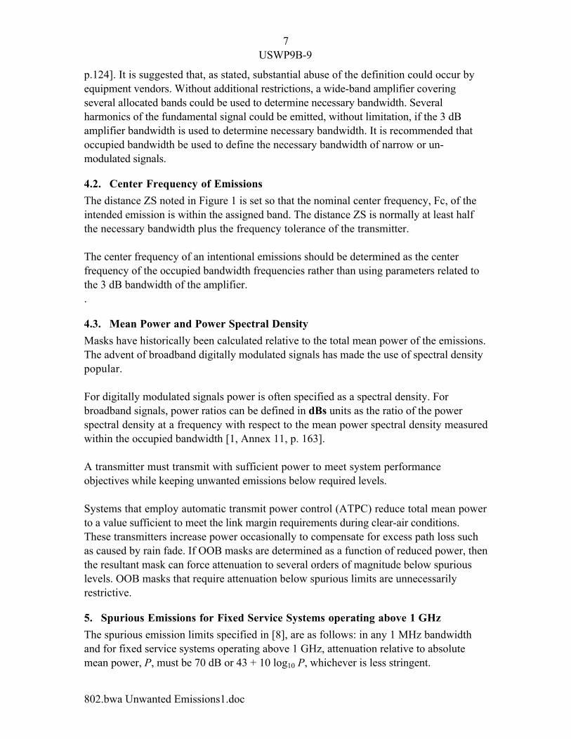
5. Spurious Emissions for Fixed Service Systems operating above 1ÊGHz
The spurious emission limits specified in [8], are as follows: in any 1 MHz bandwidthand for fixed service systems operating above 1 GHz, attenuation relative to absolutemean power, P, must be 70ÊdB or 43 + 10 log10 P, whichever is less stringent.
8USWP9B-9
802.bwa Unwanted Emissions1.doc
When a licensee operates with a payload carrier just inside the assigned frequency block,the modulation process typically produces out-of-band emissions that fall outside theassigned frequency block (Figure 2). For relatively high power transmitters, OOBemissions need to exceed the level normally allowed for spurious emissions.2
Spurious and OOB emissions are often studied separately. In this paper, both spuriousand OOB emissions are considered to highlight the discontinuity that can exist at theOOB-to-spurious boundary if one studies each region in separate documents.
6. Out of Band Emissions
A mask in the OOB frequency region is typically defined in a way that allows emissionsabove the spurious level. Administrations have adopted various limits, equations, andalgorithms for controlling the shape of the OOB mask as a function of frequency.3 Mostof the methods are a function of mean transmitter power, operating frequency, andnecessary bandwidth.
The method of calculating a mask as a function of power works fine for high powertransmitters, but for low power transmitters the same algorithm can require unwantedemissions to be far less than spurious emissions levels.
The OOB emission requirements should not require attenuation below the levels allowedfor spurious emissions because such a requirement restricts one transmitter while allowingother transmitters to emit higher unwanted emissions. Consider a transmitter site withseveral transmitters operating in different assigned bands and perhaps in differentservices. A given frequency might be in the OOB region for one transmitter and in thespurious region for several other transmitters. Interference to a victim receiver isdominated by the largest signal, which could be as high as the spurious level. If a spurioussignal is present at the allowed spurious level, effort to restrict the OOB emission tobelow spurious levels doesnÕt significantly reduce interference into the victim system.
Services that are assigned using channelized band plans [5] and fully occupy the channelrequire a two-sided mask around the necessary bandwidth. Services that are assignedusing block allocations or partially occupy a channel can safely control unwantedemissions using a one-sided mask on the side of the necessary bandwidth that fallsoutside of the assigned band.
2 For this paper, out of band (OOB) emissions are unwanted emissions that occur at frequencies offset fromthe center frequency by 50 to 250% of necessary bandwidth, and spurious emissions are all unwantedemissions at frequency offsets greater that 250% of necessary bandwidth. This definition is the same as in[3].3 For this paper, the OOB mask from US CFR47, Part 101, Para 101.111a2ii is used as an example. Therule applies in the US for fixed microwave systems operated above 15ÊGHz.

9USWP9B-9
802.bwa Unwanted Emissions1.doc
Figure 3 shows a mask that is typically used for a high power transmitter in a channelizedband. The mask is calculated for a 30 MHz necessary bandwidth (line gi) and a meanpower of +15ÊdBW. The center frequency, Fc (line gi midpoint), has been selected suchthat the lower portion of the mask is outside an assigned band (line BC). The upperportion of the mask falls inside an assigned band. Lines ab and op represent spuriousemission limits. Lines cd and lm represent the portion of the OOB mask that is limited byan attenuation of 56ÊdBc . The center frequency of the transmission is set to the lowerassigned band + Bn/2 + 0.001% Fc. A relatively high-power transmitter is shown todemonstrate a region where attenuation beyond 56 dB is not required.
The example of Figure 3 shows that unwanted emissions requirements also apply insidethe assigned band.4 While the portion of the mask outside the assigned band is anappropriate requirement, the portion of the mask inside the assigned band is unnecessarybecause the unwanted emissions will only produce self-interference to the licensee'ssystem.
4 The example uses 27.5-28.35 GHz band. Administrations often designate this band for LMDS/LMCSsystems and issue area licenses for the entire assigned band.
27.4 27.6 27.8 28.0 28.2 28.4-60
-40
-20
0
20
40
a bc d
e
g i
k
l mo
A
B C
D
Assigned Band
Mask
Figure 3, Example unwanted emissions mask typically used for a channelizedband and a high power transmitter operated near the assigned band edge. (30
MHz Necessary Bandwidth, 15ÊdBW Mean Power, 27515.28ÊMHz CenterFrequency, any 1 MHz resolution).

10USWP9B-9
802.bwa Unwanted Emissions1.doc
Figure 4 shows a mask that is typically used for a low power transmitter in a channelizedband. The mask is calculated for a 30ÊMHz necessary bandwidth (line gi) and a meanpower of 0ÊdBW. The center frequency, Fc (line gi midpoint), has been selected such thatthe lower portion of the mask is outside an assigned band (line BC). The upper portion ofthe mask falls inside an assigned band. Lines ab and op represent spurious emissionlimits. Lines cd and km represent the portion of the OOB mask that is limited by anattenuation of 56ÊdBc and is also below the level allowed for spurious emissions. Notethat in the out-of-band region, attenuation is below the spurious limits. Transmittersoperating at reduced power due to automatic power control exaggerate this example. Notealso the requirement for unwanted emission control within the assigned band. This maskis unnecessarily restrictive for block allocated bands.
7. Proposed Out-of-Band Emission Limits
Given the previous discussion, the following recommendations are made for restrictingOOB emissions:
1) OOB emission requirements apply in the 50% to 250% offset region if the frequencyis outside the assigned band.
27.4 27.6 27.8 28.0 28.2 28.4-60
-40
-20
0
20
40
a b
c d
e
g i
j
k m
o
A
B C
D
Assigned Band
Mask
Figure 4, Example emissions mask for a channelized band and a lowpower transmitter and operating near an assigned band edge. (30 MHz
Necessary Bandwidth, 0ÊdBW Mean Power, 27515.28 MHz Center frequency,any 1 MHz resolution).

11USWP9B-9
802.bwa Unwanted Emissions1.doc
2) No unwanted emission requirements apply within the assigned band other than thesame limitations as intended emissions, e.g., maximum authorized power andcoordination procedures.
3) Attenuation of OOB emissions to levels below the spurious emission limit is notrequired.
4) For multiple carrier transmitters, the necessary bandwidth of the modulated carrier orgroup of modulated carriers nearest the edge of the assigned band is taken to be theoccupied bandwidth of the transmitter. The bandwidth of the emission designator alsocorresponds with the occupied bandwidth. Carriers are assumed to be contiguous infrequency. For transmitters in which multiple carriers or groups of carriers areseparated in frequency such that carriers are not contiguous, the necessary bandwidthshould be calculated as if the carriers were contiguous. The amplifier bandwidthshould not be used unless the 3 dB points of the amplifier fall within the assignedband. The _/2 values above and below a multi-carrier emission may differ and shouldbe adjusted such that the frequencies below the lowest carrier and above the highestcarrier are the same frequencies used for the lowest and highest frequency carriersindividually.
5) The OOB mask is defined as: ÒIn any 1 MHz at frequencies outside the assignedband, attenuation relative to total mean power should be greater than 11 dB, greaterthan 11 + 0.4 (p Ð 50) + 10 log10 (Bn), less than 56ÊdB5, or power levels limited by 3)above, whichever is the less restrictive (where p is the percent of necessary bandwidthoffset from the center frequency of the emission and has a value between 50% and250% and Bn is the necessary bandwidth).Ó
6) Appendix A provides example interpretations.
8. Preliminary Draft Revision of ITU-R Recommendation F.1191
After considering the previous discussion, it appears minor adjustments to F.1191-1 areneeded. A preliminary draft revision to ITU-R Recommendation F.1191 is contained inAppendix B. The proposed changes are summarized as follows:
in Section 1.3 add, the definition of ÒAssigned BandÓ is restated from the radio regulations.
in Section 2.11, add, the phrase Òfalling outside the assigned band,Ó when determining the frequencies in whichspurious emissions apply.
5 See Footnote 3. Attenuation relative to total mean power was used in the example although an equivalentmask can be set in terms of dBs. The attenuation minimum, slope, and maximum shown here is the sameas that stated in the document from Footnote 3. The mask is suitable for intra-service sharing, which asnoted in [1, Annex 4, p. 36], may be more restrict than necessary for inter-service sharing.

12USWP9B-9
802.bwa Unwanted Emissions1.doc
Note that F.1191 is currently silent on OOB requirements.
after Section 2.12 add New Considering, that, the level of out-of-band emissions falling outside of an assigned band, should be nomore restrictive than the limit for spurious emissions (see Notes 3, 4, and 7).
add New Note 7, Unwanted emissions within an assigned band are restricted to no greater than theintentional emissions per the specified conditions of the station license.
Add New Note 8 for considering 2.1, The stated _/2 value applies to an individual carrier. The _/2 values above and below amulti-carrier emission may differ and should be adjusted such that the frequencies belowthe lowest carrier and above the highest carrier are the same frequencies used for thelowest and highest frequency carriers individually.
9. Conclusion
This document discusses several issues associated with unwanted emissions and makes aproposal for revising ITU-R Recommendation F.1191. The key points of this paperinclude: applying unwanted emission limitations only outside the stationÕs assigned band,not requiring OOB limitations below spurious emission levels, and not using amplifier3ÊdB bandwidth to determine unwanted emission parameters.

13USWP9B-9
802.bwa Unwanted Emissions1.doc
References
1. Chairman T/G 1/5, ÒReport of the Third Meeting of Task Group 1/5, Ò Munich, 9-15July 1998, Doc 1-5/92, 14 Aug 1998
2. ITU-R Recommendation SM.328-8, ÒSpectra and Bandwidth of Emissions,Ó 1994.3. ITU-R Recommendation SM.329-7, ÒSpurious Emissions,Ó 1997.4. ITU-R Recommendation F.1191-1, ÒBandwidth and Unwanted Emissions of Digital
Radio-Relay SystemsÓ5. ITU-R Recommendation F. 746, ÒRadio Frequency Channel Arrangements for Radio-
Relay Systems.Ó6. ITU Study Group 9,ÓDraft Revision of Recommendation ITU-R F.755-1 Point-to-
Multipoint systems in the Fixed Service,Ó SG9/74(rev 2)-E, 21 Oct. 1998.7. ITU Study Group 9, ÒDraft Revision of Recommendation ITU-R F1332 Radio
Frequency Transport through Optical Fibres,Ó SG9/48-E, 13 Oct 98.8. ITU WRC-97 Final Acts, ÒSpurious Emission Limits for Transmitters installed after
1ÊJanuary 2003 and for all Transmitters after 1 January 2012,Ó Appendix S3.

14USWP9B-9
802.bwa Unwanted Emissions1.doc
Appendix A
Examples of Out Of Band Emission Masks Relative to an Assigned Band6
Figure A-1 shows the mask proposed by Section 7 calculated for a high powertransmitter. The mask is based on one RF carrier operating near the lower edge of theassigned band and one RF carrier operating near the upper edge of the assigned band. Bothcarriers have 30 MHz necessary bandwidth. Lines ab and km are spurious emissionlimits. Lines cd and hj are OOB limits in which attenuation beyond 56ÊdBc is notrequired. Note there is no mask requirement inside the assigned band.
Figure A-1 Unwanted emissions mask as defined in Section 7 for a high-power transmitter with carrier just inside the assigned band. (Two 32 Watts mean
power carriers, two 30 MHz bandwidth carriers, 27,515.28 MHz lower carriercenter frequency, 28,334.73 MHz upper carrier center frequency, any 1 MHz
resolution).
6 The examples in this Appendix use the 27.5-28.35 GHz band. Administrations often designate this bandfor LMDS/LMCS systems and issue area licenses for the entire assigned band.
27.4 27.6 27.8 28.0 28.2 28.4 28.6-60
-40
-20
0
20
40
a bc d
e g
hi j k
A
B C
D
Assigned Band
Mask Mask
15USWP9B-9
802.bwa Unwanted Emissions1.doc
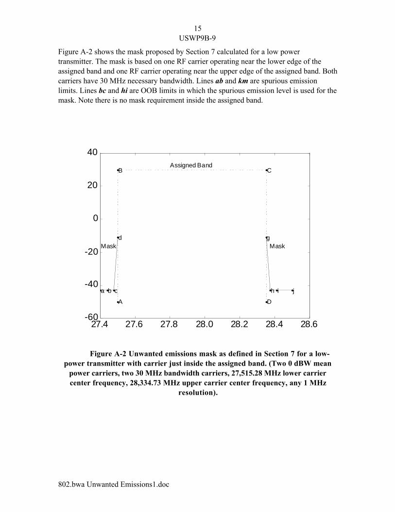
Figure A-2 shows the mask proposed by Section 7 calculated for a low powertransmitter. The mask is based on one RF carrier operating near the lower edge of theassigned band and one RF carrier operating near the upper edge of the assigned band. Bothcarriers have 30ÊMHz necessary bandwidth. Lines ab and km are spurious emissionlimits. Lines bc and hi are OOB limits in which the spurious emission level is used for themask. Note there is no mask requirement inside the assigned band.
Figure A-2 Unwanted emissions mask as defined in Section 7 for a low-power transmitter with carrier just inside the assigned band. (Two 0ÊdBW mean
power carriers, two 30 MHz bandwidth carriers, 27,515.28 MHz lower carriercenter frequency, 28,334.73 MHz upper carrier center frequency, any 1ÊMHz
resolution).
27.4 27.6 27.8 28.0 28.2 28.4 28.6-60
-40
-20
0
20
40
a b c
d g
h i j
A
B C
D
Assigned Band
Mask Mask

16USWP9B-9
802.bwa Unwanted Emissions1.doc
Appendix B,
Preliminary Draft Revision to RECOMMENDATION ITU-R F.1191-1
BANDWIDTHS AND UNWANTED EMISSIONS OF DIGITALRADIO-RELAY SYSTEMS*
(Question ITU-R 119/9)
(1995-1997)Rec. ITU-R F.1191-1
The ITU Radiocommunication Assembly,
consideringa) that the definitions of necessary and occupied bandwidth and allocated band arereported in Nos. 146, 147 andÊ17 of the Radio Regulations (RR) respectively;b) that the definitions of unwanted, out-of-band and spurious emissions are reportedin RR Nos. 140, 138 and 139 respectively;c) that it is necessary to give guidance for the application of these definitions todigital radio-relay systemsÊ(DRRS);d) that it is relatively unlikely that out-of-band emissions from DRRS will causesignificant interference into systems operating in adjacent bands, because:Ð the power spectrum of a DRRS decays rapidly outside the occupied bandwidth;
Ð the e.i.r.p. of line-of-sight DRRS is low or medium;
Ð trans-horizon DRRS employing a high e.i.r.p. are not widely used;e) that from the viewpoint of interference into other systems sharing the samefrequency band, interference due to out-of-band emissions will be, in general, lesssignificant than that due to emissions within the necessary bandwidth;f) that intra-system interference related problems, which may be caused byunwanted emissions, are normally taken into account by DRRS designers;g) that bands are allocated to radio-relay fixed services on a primary or co-primarybasis, where a radio-frequency channel arrangement has been established by a relevantITU-R Recommendation or by a National Regulatory Authority;h) that transmitter frequencies should be determined so that out-of-band emissionsdo not cause harmful interference outside the allocated band in accordance with RR No.343 (S4.5); the transmitters on the radio-frequency channels at the allocated band edgesshould comply with the general occupied bandwidth compatibility criteria as required byRR No. 147;j) that at the allocated band edges, radio-frequency bands ZS, as defined inRecommendation ITU-R F.746, are given by the relevant ITU-R Recommendations inorder to control power spill-over into adjacent allocated bands;k) that it is not always possible or convenient to make the occupied bandwidth ofDRRS smaller than or equal to the bandwidth of the radio-frequency channel provided by
* This Recommendation should be brought to the attention of Radiocommunication Study Group 1(TG 1/5).

17USWP9B-9
802.bwa Unwanted Emissions1.doc
the relevant radio-frequency channel arrangement established for the allocated band byITU-R or by a National Regulatory Authority;l) that within the allocated band, coordination between various radio-relay systemsused on the basis of a radio-frequency channel arrangement is covered by an efficientconcept summarized by RecommendationÊITU-RÊF.746Êand by the statistical propagationbehaviour reported in Recommendation ITU-R P.530 andRecommendationÊITU-RÊF.1093;m) that DRRS, with suitable scrambling applied, have in general a transmittedspectral density and unwanted emissions with power peak factors that may beconservatively considered noise-like;n) that DRRS have unwanted emissions composed of both noise-like and discretecomponents, made up of out-of-band and spurious emissions, which are not easy todistinguish one from the other;
18USWP9B-9
802.bwa Unwanted Emissions1.doc
o) that Recommendation ITU-R SM.329 gives the limits and the reference bandwidthfor spurious emissions of all services, including the fixed service;p) that Recommendation ITU-R SM.329 defines the frequency boundary betweenspurious and out-of-band emissions as ±Ê250% of the necessary bandwidth; howeverallowance is given for different definitions, and this frequency boundary may bedependent on the type of modulation used, the maximum bit rate in the case of digitalmodulation, the type of transmitter, and frequency coordination factors. For example, inthe case of some digital systems, the frequency boundary may need to differ from the±Ê250% factor (see Note 3);q) that, in fixed service applications, different emissions with different modulationformats and necessary bandwidth may co-exist in the same channel separation; it istherefore convenient, for ease of frequency coordination and for regulatory purposes, toconsider the 250% of the constant channel separation as the boundary between out-of-band and spurious emissions, instead of the various different necessary bandwidths ofany specific system (see Note 3),
recommends1 that the following general definitions apply to DRRS:
1.1 Occupied bandwidth
The width of a frequency band such that, below the lower and above the upper frequencylimits, the mean powers emitted are each equal to a specified percentage β/2 of the totalmean power of a given emission (RR Article 1, No.Ê147).
1.2 Necessary bandwidth
For a given class of emission, the width of the frequency band which is just sufficient toensure the transmission of information at the rate and with the quality required underspecified conditions (RR Article 1, No. 146).
1.3 Allocated frequency band
Allocation (of a frequency band): entry in the Table of Frequency Allocations of a givenfrequency band for the purpose of its use by one or more terrestrial or spaceradiocommunication services or the radioastronomy service under specific conditions.This term shall also be applied to the frequency band concerned (RR Article 1, No. 17).For DRRS the allocated frequency band may be considered as the overall frequency bandallocated to the FS on a primary or co-primary basis.
1.3.x Assigned Frequency BandAuthorization given by an administration for a radio station to use a radio frequency orradio frequency channel under specified conditions. (RR Article 1, No. 19)
1.4 Radio-frequency channel separation

19USWP9B-9
802.bwa Unwanted Emissions1.doc
Bandwidth equal to the frequency separation, defined in Recommendation ITU-R F.746,of adjacent channels of the relevant radio-frequency channel arrangement establishedwithin the allocated frequency band.
1.5 Guardband
Bandwidth equal to the frequency separation, defined in Recommendation ITU-R F.746as ZS, between the nominal centre frequency of the outermost channel of a radio-frequency channel arrangement and the limit of the allocated band.
1.6 Unwanted emissions
Consist of spurious emissions and out-of-band emissions (RR Article 1, No. 140).For DRRS an example of a typical scenario is reported in Fig. 2.
1.7 Out-of-band emission
Emission on a frequency or frequencies immediately outside the necessary bandwidthwhich results from the modulation process, but excluding spurious emissions (RR Article1, No. 138).
1.8 Spurious emission
Emission on a frequency or frequencies which are outside the necessary bandwidth andthe level of which may be reduced without affecting the corresponding transmission ofinformation. Spurious emissions include harmonic emissions, parasitic emissions,intermodulation products and frequency conversion products, but exclude out-of-bandemissions (RR Article 1, No. 139);2 that the following specific design objectives and definitions be used for DRRS; anillustration of those objectives and definitions can be found in Fig. 1;2.1 that, for DRRS, the value of percentage β/2 should be taken as 0.5% (Note 8);2.2 that, for DRRS, the necessary bandwidth is to be considered to have the samevalue as the occupied bandwidth;2.3 that, according to the type of the utilized radio-frequency channel arrangement(see Note 1), the capacity and the modulation format of the transmitted signal, similarDRRS could have a necessary bandwidth which is no more than 20% wider than theradio-frequency channel separation (see Note 1); however, since dissimilar systemsoperating in the same band could give rise to certain incompatibilities, the relationshipbetween the RF channel separation and the necessary bandwidth requires further study;2.4 that the determination of occupied bandwidth should be done with a spectrumanalyser method described in Recommendation ITU-R SM.328 or, whenever possible, bynumerical evaluation or integration of the actual emitted spectrum as reported in Annex 1;2.5 that when burst transmission is used (e.g. for TDMA DRRS) the evaluation ofbandwidths and emissions should be done averaging the power over burst duration;2.6 that DRRS should use suitable scrambling circuitry in order to maintain all thespectral emissions (both wanted and unwanted) independent from the input data stream;
20USWP9B-9
802.bwa Unwanted Emissions1.doc
2.7 that any unwanted emission which falls at frequencies separated from the centrefrequency of the emission by less than 250% of the relevant channel separation, wherethe system is intended to be used, will generally be considered out-of-band emission (seeNotes 3 and 4);2.8 that any unwanted emission which falls at frequencies separated from the centrefrequency of the emission by 250% or more of the relevant channel separation, where thesystem is intended to be used, will generally be considered spurious emission (see Notes3 and 4);2.9 that, above and below the limits of the necessary bandwidth, the permissible meanpower level of unwanted emission should be less than or equal to 0.5% of the totaltransmitted mean power taken at the radio antenna port (seeÊNoteÊ2);2.10 that, from the viewpoint of the international regulations, it is presently notnecessary to establish any additional limitation on the spectral shape of unwantedemissions from DRRS;2.11 that the levels of spurious emissions falling outside of an assigned band of thestation, the frequency range to their measurement and the reference bandwidth in whichlevels are specified should be those defined by ITU-R Recommendation SM.329 asdetailed in Annex 2 (seeÊNotes 3, and 5, and 7);
2.12 that, without other specific agreement between administrations sharing the sameband edge, the digital radio-relay transmitters operating on the outermost channelfrequencies of a radio-frequency channel arrangement should have an occupied bandwidthso that the outermost halfÊof it, when added to the absolute value of the frequencytolerance (see Note 6), results in a bandwidth smaller than or equal to the value of ZS asdefined in ¤ 1.5.
2.13 that, the level of out-of-band emissions falling outside of an assigned band of thestation, should be no more restrictive than for spurious emissions (see Notes 3, 5, and 7).
NOTEÊ1ÊÐÊSee Recommendation ITU-R F.746 for definitions of alternated, co-channel mode band re-useand interleaved mode band re-use radio-frequency channel arrangements. Channel separation is defined asXS/2 for alternated frequency channel arrangements and XS for co-channel and interleaved frequency channelarrangements.
NOTEÊ2ÊÐÊDue to possible compatibility problems, caution should be exercised when applying thisRecommendation to high capacity systems, bands which have dissimilar systems in adjacent channels, andbands which are shared with other services.
NOTEÊ3ÊÐÊAs Recommendation ITU-R SM.329 allows for boundary values differentthan ±250%, the following is provisionally recommended for DRRS operating above1ÊGHz with channel separation less than 2ÊMHz:Ð that the boundary between the spurious and out-of-band emissions is established as ±Ê500% of the
channel separation;
Ð that the reference bandwidth is 100 kHz in the frequency range between this boundary and ±Ê20 MHzof the nominal centre frequency;

21USWP9B-9
802.bwa Unwanted Emissions1.doc
and also for DRRS operating above 1 GHz with transmitter power 20 watts or more andwith channel separation between 2 MHz and 14 MHz:Ð that the boundary between the spurious and out-of-band emissions is established as ±Ê250% of the
channel separation;
Ð that the reference bandwidth is 100 kHz in the frequency range between this boundary and ±Ê70 MHzof the nominal centre frequency.
NOTEÊ4ÊÐÊWhen the radio-relay system is intended for use in a frequency band where an RF channelarrangement has not been established, the necessary bandwidth should be used, instead of channelseparation, in evaluating the 250% boundary.
NOTEÊ5ÊÐÊIt is recognized that the reference bandwidth of 1 MHz may result in spectral densityrequirement of up to 24ÊdB more stringent than with the 4ÊkHz bandwidth given in the previous version ofthis Recommendation. Applicability of these new limits to the existing systems will be subject to nationalregulations or regulations eventually established by World Radiocommunication Conference, (Geneva,1997) (WRC-97).
NOTEÊ6ÊÐÊThe precise specification of frequency tolerance values is left to the National RegulatoryAuthorities.NOTE 7 Ð U nwanted emissions within an assigned band are restricted to no greater than intentionalemissions per the specified conditions of the station license. NOTE 8 Ð The stated _/2 value applies to an individual carrier. The _/2 values above and below a multi- carrier emission may differ and should be adjusted such that the frequenc ies below the lowest carrier andabove the highest carrier are the same frequenc ies used for the low est and highest frequency carrier s individually.
(The remaining pages of ITU-R Recommendation F.1191-1 not changed and therefore notreplicated)
FIGURE 1..[1191-01] = page pleine � l'italienne