Bombas hidráulicas PV Hydraulic...
28
PV Bombas hidráulicas Hydraulic motors Reparaciones Repairs Ref : 800178191L REPAR.PV E/GB Rev : A – Feb 2000 POCLAIN HYDRAULICS Industrie B.P. 106 60411 VERBERIE CEDEX - FRANCE Tel.: 33 3 44 40 77 77 Fax: 33 3 44 40 77 99 www.poclain-hydraulics.com POCLAIN HYDRAULICS Certifié ISO 9001 054 064 075 089 105 PV 0334 Reparación de las averías Trouble Shooting Mantenimiento Maintenance Reparaciones Repairs Piezas de repuesto Spare parts
Transcript of Bombas hidráulicas PV Hydraulic...

PVBombas hidráulicasHydraulic motors
ReparacionesRepairs
Ref : 800178191L
REPAR.PV E/GB
Rev : A – Feb 2000
POCLAIN HYDRAULICS IndustrieB.P. 10660411 VERBERIE CEDEX - FRANCETel.: 33 3 44 40 77 77Fax: 33 3 44 40 77 99www.poclain-hydraulics.com
POCLAIN HYDRAULICS
Certifié ISO 9001
054 064 075 089 105PV �� �� �� �� ��
0334
Reparación de lasaverías
Trouble Shooting
MantenimientoMaintenance
ReparacionesRepairs
Piezas de repuestoSpare parts

POCLAIN HYDRAULICS
2 REPAR.PV E/GB 800178191L
Este documento, dirigido a los fabricantes de máquinas y circuitos queusen productos POCLAIN HYDRAULICS, presenta las recomenda-ciones para la instalación y puesta en marcha que permiten asegurarun funcionamiento óptimo de estos sistemas.
Es aconsejable que todas las operaciones las lleven a cabo técnicoscon una formación específica, previa lectura y comprensión de lainformación facilitada en este documento y con autorización del fabri-cante de la máquina.Es indispensable que los técnicos respeten las instrucciones deseguridad a fin de evitar daños.Este documento contiene avisos de seguridad importantes, presenta-dos de la siguiente forma:
! Advertencia.
Incluye asimismo instrucciones esenciales para el funcionamiento delproducto e información general, que se identifican del modo siguiente:
Instrucción importante.
Información general.
POCLAIN HYDRAULICS diseña productos que sus clientes integrana máquinas que ellos fabrican. Por esta razón, POCLAINHYDRAULICS no acepta responsabilidad alguna por errores deriva-dos de una integración deficiente de sus productos o de una configu-ración errónea de sus dispositivos ajustables. POCLAINHYDRAULICS tampoco se hace responsable de instrucciones deoperación y mantenimiento incompletas o erróneas facilitadas al usua-rio final por el fabricante de la máquina ni de los fallos que pudieraocasionar la aplicación de los procesos recomendados en este docu-mento.Cualquier modificación de los parámetros de los dispositivos ajusta-bles podría requerir una nueva homologación de las máquinas.
Para ofrecer un servicio de la mejor calidad, recomendamos a nues-tros clientes que sometan todas las aplicaciones a la aprobación dePOCLAIN HYDRAULICS.Si el usuario abre los productos, anula la garantía.Utilice únicamente piezas de repuesto fabricadas por POCLAINHYDRAULICS. El uso de piezas de otros fabricantes podría disminuirel rendimiento del sistema y provocar un riesgo de seguridad.
En su afán de perfeccionamiento, POCLAIN HYDRAULICS se reser-va el derecho de realizar, sin previo aviso, todas las modificacionesque considere necesarias para la mejora de los productos descritos eneste documento.
Este documento incluye secciones escritas en español y secciones encursiva que constituyen la traducción al inglés de la versión francesa.En caso de dudas, la versión francesa servirá como referencia.Las medidas se expresan en unidades métricas. Los valores corres-pondientes a otros sistemas de medida (en especial anglosajones) seofrecen a título indicativo.
Las ilustraciones no son contractuales.
POCLAIN HYDRAULICS Industrie 1998.La marca POCLAIN HYDRAULICS es propiedad de POCLAINHYDRAULICS S.A.Este documento, propiedad de POCLAIN HYDRAULICS Industrie, esestrictamente confidencial. Queda prohibido su uso, reproducción,copia o divulgación total o parcial por terceros sin nuestra autorizaciónprevia y por escrito.
FACOM es una marca registrada de FACOM SA.LOCTITE es una marca registrada de LOCTITE SA.AUTO-TOP es una marca registrada de AGIP SPA.
This document is provided to machine manufacturers integratingPOCLAIN-HYDRAULICS products. It suggests basic installationspecifications and commissioning processes that manufacturers mayutilize to assure optimal functioning of the products.
It is recommended that any operation be performed by engineerstrained accordingly. The engineers schould read and understand theinformation given in this document and be authorized by the machinemanufacturer.It is essential that the engineers comply with safety instructions toprevent injury.
This document includes major safety warnings announced in thisway:
! Safety warning.
Additionally, this document includes instructions essential to productfunction as well as those providing general information. Both areannounced similar to the following examples:
Essential instruction.
General information.
POCLAIN HYDRAULICS designs products which are integrated byits customers in the machines they design. Subsequently, POCLAINHYDRAULICS disclaims liability for consequences of improper inte-gration of its products and of improper set-up of adjustable devices. Inthe same way, POCLAIN HYDRAULICS may not be liable for in-complete or improper operating and maintenance instructions pro-vided to the end user by the machine manufacturer nor for failuresresulting from operations performed by any person using these sug-gested procedures.A re-certification of the machine may be required for every change inset-up of adjustable devices.
In order to offer the best quality service, POCLAIN HYDRAULICSrecommends to its customers to have applications approved byPOCLAIN HYDRAULICS.
Opening of products voids the warranty contract.
Use only POCLAIN HYDRAULICS genuine spare parts. Using partsfrom different source could reduce the performance of the compo-nents or systems and pose a safety hazard.
In accordance with its policy of continuous improvement, POCLAINHYDRAULICS reserves the right to modify the specifications of allproducts described herein without prior notice.
This document contains sections written in French and sectionsprinted in italics composing the English translation of the Frenchsections.The French sections will be the reference in case of dispute.All measures are expressed in metric units. Converted values to othersystems (notably US and UK) are given for reference only.
The illustrations for information only.
POCLAIN HYDRAULICS Industrie 1998.The trademark POCLAIN HYDRAULICS is the property of POCLAINHYDRAULICS S.A.This document is the property of POCLAIN HYDRAULICS Industrie.It is strictly confidential. It must not be used, duplicated, copied ordisclosed to a third party in full or in part without our prior writtenconsent.
FACOM is FACOM SA registered trademark.LOCTITE is LOCTITE SA registered trademark.AUTO-TOP is AGIP SPA registered trademark.

POCLAIN HYDRAULICS
800178191L REPAR.PV E/GB 3
Índice
ÍNDICE .....................................................................3
SEGURIDAD Y CALIDAD ........................................4
ANTES DE LA INTERVENCIÓN.........................................4DURANTE LA INTERVENCIÓN .........................................4DESPUÉS DE LA INTERVENCIÓN .....................................4
IDENTIFICACIÓN.....................................................5
LOCALIZACIÓN Y REPARACIONES DE AVERÍAS 6
REPARACIONES ................................................... 10
SUSTITUCIÓN DE LA BOMBA ........................................ 10Desmontaje ......................................................... 10Reinstalación....................................................... 10
SUSTITUCIÓN DE LAS VÁLVULAS .................................. 11Desmontaje ......................................................... 11Reinstalación....................................................... 13
SUSTITUCIÓN DEL RETÉN DEL EJE ............................... 14Desmontaje ......................................................... 14Reinstalación....................................................... 14
SUSTITUCIÓN DE UNA BOMBA AUXILIAR......................... 15Desmontaje ......................................................... 15Reinstalación....................................................... 15
SUSTITUCIÓN DE LA BOMBA DE PRELLENADO ................ 16Desmontaje ......................................................... 16Reinstalación....................................................... 17
SUSTITUCIÓN DEL SENSOR DE VELOCIDAD (OPCIONAL)...19Desmontaje ......................................................... 19Reinstalación....................................................... 19
SUSTITUCIÓN DEL SISTEMA DE MANDO ......................... 20Desmontaje ......................................................... 20Reinstalación....................................................... 20
SUSTITUCIÓN DEL SENSOR DE DOBLAJE (MANDO SA). ...21Desmontaje. ........................................................ 21Reinstalación....................................................... 22
SUSTITUCIÓN DE LAS BOBINAS (MANDO SA)................. 23Desmontaje. ........................................................ 23Reinstalación....................................................... 23
HERRAMIENTAS STANDARD............................... 24
PIEZAS DE REPUESTO ........................................ 25
Table of contents.
TABLE OF CONTENTS........................................... 3
SAFETY AND QUALITY.......................................... 4
BEFORE SERVICING..................................................... 4DURING SERVICING ..................................................... 4AFTER SERVICING ....................................................... 4
IDENTIFICATION..................................................... 5
TROUBLE SHOOTING............................................ 7
REPAIRS. .............................................................. 10
REPLACEMENT OF THE PUMP...................................... 10Removal. ............................................................ 10Reinstallation. ..................................................... 10
REPLACEMENT OF THE RELIEF VALVES......................... 11Disassembly. ...................................................... 11Reassembly........................................................ 13
REPLACEMENT OF THE SHAFT SEAL ............................. 14Disassembly ....................................................... 14Reassembly. ....................................................... 14
REPLACEMENT OF THE AUXILIARY PUMP....................... 15Removal. ............................................................ 15Reinstallation. ..................................................... 15
REPLACEMENT OF THE BOOST (CHARGE) PUMP. ........... 16Disassembly. ...................................................... 16Reassembly. ....................................................... 17
REPLACEMENT OF THE SPEED SENSOR (OPTIONAL). ...... 19Disassembly. ...................................................... 19Reassembly........................................................ 19
REPLACEMENT OF THE CONTROL SYSTEM. ................... 20Removal ............................................................. 20Reinstallation ...................................................... 20
REPLACEMENT OF THE FEEDBACK SENSOR (SA CONTROL).21Disassembly. ...................................................... 21Reassembly........................................................ 22
REPLACEMENT OF THE SOLENOID (SA CONTROL). ........ 23Disassembly. ...................................................... 23Reassembly........................................................ 23
STANDARD TOOLING.......................................... 24
SPARE PARTS...................................................... 25

POCLAIN HYDRAULICS
4 REPAR.PV E/GB 800178191L
Seguridad y calidad
Antes de la intervención• Tome todas las medidas necesarias para evitar
daños personales y materiales, ajustándose a lasnormas de seguridad en vigor.
• Coloque el freno de estacionamiento e inmovilice lamáquina con calces.
• Pare el generador de energía (motor) del sistemahidráulico y desconecte la alimentación eléctrica.
• Si es necesario, delimite una zona de seguridad.
• Lave el exterior de los componentes para eliminarcualquier rastro de lodo y grasa.
• Espere a que el sistema hidráulico se enfríe y se des-presurice por completo (descargue los acumuladores).
• Vacíe el fluido hidráulico que pudiera quedar en loscárteres de los componentes. Recoja el fluido usadoy elimínelo sin contaminar el medioambiente.
! El fluido hidráulico caliente o bajo presión puedeprovocar quemaduras graves e infecciones. Consulte a un médico en caso de accidente.
Durante la intervención• Algunos componentes hidráulicos son muy pesados.
Sujételos con un puente elevador de capacidadadecuada para retirarlos del chasis.
• La limpieza es fundamental para el buen funciona-miento de los componentes hidráulicos. La mayoría delas piezas pueden limpiarse con un solvente limpio.
• Cuando utilice el sistema, proteja todas las superficies sensi-bles a los golpes (zonas de centrado, superficies de frota-miento y soporte, vanos de juntas y rodamientos, etc.).
• Limpie estas superficies antes de volver a montarlas.• Instale siempre juntas nuevas y elimine sistemáti-
camente las juntas desmontadas. Le recomenda-mos que lubrique todas las juntas antes del monta-je.
• Engrase todas las superficies de rozamiento apli-cándoles una película de fluido hidráulico limpia quegarantizará un lubrificado correcto durante el primerarranque.
• No caliente nunca el fluido hidráulico, pues puedeinflamarse a altas temperaturas. Algunos solventestambién son inflamables. No fume durante la insta-lación.
Después de la intervención Vuelva a instalar los componentes y ponga en funcio-namiento el sistema hidráulico según las instruccionesque figuran en los siguientes documentos:• INSTAL PV E/GB (ref. 800178189J)• INSTAL CIRCUITS E/GB (ref. 800178187Z)
! No sobrecargue las válvulas de seguri-dad.
Safety and Quality
Before servicing• Be extremely careful to prevent personal injury and
to avoid damage to material. Comply with all safetyregulations.
• Apply the parking brake and prevent the machinefrom rolling with tire blocks.
• Stop the hydraulic system power source (engine)and disconnect the battery.
• If necessary, block off the safety area.• Wash dirt and grease from exterior of the compo-
nents.• Await the complete cooling down and depressuriza-
tion of the hydraulic system (accumulators must bepurged).
• Flush the casings of the hydraulic componentswhich may retain hydraulic fluid. Collect the old hy-draulic fluid preventing contamination of the envi-ronment.
!Hot or pressurized hydraulic fluid may causeserious burns & infections to the human body.Consult a physician in case of accident.
During servicing• Some hydraulic components are very heavy. Se-
cure them with a lifting device of adequate capacitywhen removing from the machine frame.
• Cleanliness is essential to functioning of the hydrau-lic components. Most of the parts may be cleanedwith a clean solvent.
• During handling, protect all sensitive surfaces fromshocks (piloting and interface surfaces, thrust &bearings surfaces, seal races, etc...)
• Clean up these surfaces before reassembly.
• Always install new O-rings, seals & gaskets dis-carding the old ones. We recommend lubricating allseals prior to assembly.
• Lubricate all surfaces which have relative motionbetween parts by coating them with a film of cleanhydraulic fluid to assure lubrication at first start.
• Never heat hydraulic fluid, as it may flame at hightemperature. Some solvents are also flammable.Do not smoke during servicing.
After servicing
Reinstall the components and restart the hydraulicsystem according to instructions defined in the followingdocuments:• INSTALLATION PV F/GB (ref. 677777843J)• INSTALL CIRCUITS F/GB (ref. 677777831V)
! Do not overset relief valves.

POCLAIN HYDRAULICS
800178191L REPAR.PV E/GB 5
Identificación Identification.
A: Designación comercial de la bomba. Ej.: PVA 40RAMA10A100 B: Código: Código del artículo de la bomba Ej.: 004643501D C: Serie: Número de fabricación de la bomba Ej.: B310131JB
Para un pedido de piezas de repuesto,indique el código del artículo, el númerode serie de la bomba y el número de refe-rencia de la pieza. Consulte las páginas24 a 27.
A : Commercial description.Ex : PVA 40RAMA10A100
B : Code : Part number.Ex : 004643501D
C : Series : Manufacturing serial number.Ex : B310131JB
The part number and the serial numberof the pump as well as the part itemnumber (see pages 24-27) must be speci-fied to order spare parts.
B310131JB
PV 40RAMA10A100
004643501DC
A
B

POCLAIN HYDRAULICS
6 REPAR.PV E/GB 800178191L
LOCALIZACIÓN Y REPARACIONES DE AVERÍAS
AVERÍAS CAUSAS SOLUCIONES
Filtros obstruidos Renovar cartuchos
Canalización de aspiración Limpiarla
obstruida
La bomba no aspira Falta de fluido Llenar el depósito hasta el nivelnormal
Bombas de prellenado o auxiliardeterioradas
Repararla o sustituirla
Sentido erróneo de rotación Invertir el sentido
Sentido erróneo de rotación Invertir el sentido
Acoplamiento motobombadeteriorado
Repararlo o sustituirlo
CAUDAL Válvula HP deteriorada Repararla
BAJO O Deficiente en Imposibilidad de hacer que Inversor no alimentado Repararlo o sustituirlo
VELOCIDAD los dos sentidos el caudal varíe o con aceite o bobinas
DEL caudal nulo no excitadas
RECEPTOR Surtidores obstruidos Repararlos o sustituirlos
INSUFICIENTE Caudal incontrolado La palanca se desplaza sola Sustituir la bomba
Válvula de sobrealimentación
abierta o rota Repararlos o sustituirlos
Inversor bloqueado
Deficiente en Escapes muy grandes en una posición
un sólo sentido en una de las ramascircuito HP
La válvula de cambiopermanece bloqueada
en 1 posición
En punto neutro, comprobar lapresión de prellenado
Escapes receptor superiores Verificar los escapes
al caudal de prellenado Escape externo excesivo Verificar los escapes
Demasiado débil Válvula HP con calibrado Sustituirla
demasiado débil o dañada
Demasiado fuerte Válvula HP con calibrado Sustituirla
PRESIÓN demasiado fuerte o dañada
Presencia de aire en el fluido Purgar el circuito
Irregular Fluido contaminado Sustituirlo
Válvula HP usada Sustituirla

POCLAIN HYDRAULICS
800178191L REPAR.PV E/GB 7
TROUBLE SHOOTING.
TROUBLES CAUSES REMEDIES
Clogged filters Renew cartridges
Obstructed suction line Clean it
No pump suction Lack of fluid Fill the tank up
to normal level
Charge pump or auxiliary Recondition
pump damaged or replace
Wrong rotation Reverse the way
Wrong rotation Reverse the way
Coupling of the pump Recondition
damaged or replace
LOW FLOW Wrong in both ways Impossible to vary Damaged HP valve Recondition
OR BAD The flow or no flow at all or replace
RECEIVER Reverser not fed with oil Recondition
SPEED or coils not excited or replace
Electrical cylinder not fed Check electrical circuit or
or damaged. replace cylinder
Uncontrolled flow Lever moves by itself Replace pump
Check valve open
or broken Recondition
Reverser blocked or replace
Wrong in one way only Heavy leaks in a position
in one of the circuit lines Exchange valve remains At neutral point,
blocked in one position check boost pressure.
Receiver leaks higher than Check the leaks
the boost flow
Excessive internal leak Check leaks
Too low Too low HP valve setting Replace
or damaged HP valve
Too high Too high HP valve setting Replace
PRESSURE or damaged HP valve
Air in the fluid Bleed the circuit
Irregular
Contaminated fluid Replace it
Worn HP valve Replace it

POCLAIN HYDRAULICS
8 REPAR.PV E/GB 800178191L
AVERÍAS CAUSAS SOLUCIONES
Presión de función del circuitodemasiado alta
Ajustar la presión
Componentes del circuitousados (escapes)
Repararlos o sustituirlos
Temperatura del fluido de-masiada alta
Viscosidad del fluidoincorrecta
Renovar el fluido
Refrigeración insuficiente Controlar el funcionamiento orevisar la instalación
Fluido contaminado ode mala calidad
Renovar el fluido
Fluido contaminado ode mala calidad
Renovar el fluido
CALOR En una utilización Filtros obstruidos Renovar cartuchos
EXCESIVO intensa y suave Controlar calibrado válvulas
Cambio de aceite insuficiente prellenado y cambio
Velocidad demasiado alta Ajustar la velocidad
Bomba de prellenado deteriora-da
Repararla o renovarla
Presencia de aireen el fluido
Apretar conexiones de aspira-ción, llenar el depósito hasta elnivel correspondiente, purgar el
aire encerrado en el circuito El servomecanismo Escapes en el circuito Repararla o renovarla
Sólo en una utilización no funciona bomba-válvula de cambio intensa El servomecanismo Válvulas HP calibradas Repararla o renovarla
funciona demasiado bajo o desgastadas Falta de fluido Llenar el depósito hasta
el nivel normal Falta de fluido Llenar el depósito hasta
el nivel normal Filtros obstruidos Sustituirlos
Canalización de aspiración Limpiarla
obstruida Alimentación deficiente Fluido contaminado Sustituirlo
de la bomba Toma de aire del depósitoobstruida
Limpiarla
En aumento con Velocidad demasiado alta Ajustarla
la inclinación de la placa Calibración o estado de las Controlar calibrado
válvulas de prellenado y o EXCESO DE cambio reparar
RUIDOS Presión deprellenado
demasiado baja < 17 bar
Bomba de prellenado deteriora-da
Repararla o sustituirla
Escapes abundantes en los componentes Verificar los escapes
del circuito Apretar conexiones de
En aumento con la inclinación Presencia de aire aspiración, llenar el depósito
en el fluido hasta el nivel correspondiente,purgar el aire
y sin inclinación de la placa encerrado en el circuito,
cambiar la junta del árbol de labomba
Alineamiento erróneo de lamotobomba
Ajustarla o sustituirla
Bomba deteriorada Repararla o sustituirla

POCLAIN HYDRAULICS
800178191L REPAR.PV E/GB 9
TROUBLES CAUSES REMEDIES
Warn circuit component Recondition
(leaks) or replace
Circuit operating Adjust pressure
pressure too high
Too high fluid Incorrect fluid viscosity Replace fluid
temperature
Insufficient cooling Check operating conditions
or check the installation
Contaminated or poor Replace fluid
quality fluid
Contaminated or poor Replace fluid
quality fluid
Clogged filters Replace cartridges
EXCESSIVE High and low utilization Insufficient oil Check LP valve setting
HEAT exchange
Too high speed Adjust speed
Damaged boosting Recondition
pump or replace
Tighten suction
Air in the fluid connections, fill tank
up to level, bleed
air closed in circuit
Servo-positioner doesn’t Leaks in the pump to Recondition
High utilization only work anymore exchange valve circuit or replace
Servo-positioner Setting of HP valves too Recondition
works low or worn valves or replace
Lack of fluid Fill tank up
to normal level
Lack of fluid Fill tank up
to normal level
Clogged filters Replace them
Clean them
Bad pump feeding Contaminated fluid Replace it
Clogged tank air intake Clean it
Increasing with swash Too high speed Replace it
plate incline Setting or recondition of Check setting
EXCESSIVE the boost and or
NOISE exchange valves recondition
Boosting pressure Damaged boosting Recondition
too low <17 bar pump or replace
Heavy leaks
at the Check leaks
circuit components
Tighten the suction
Increasing with swash connections, fill tank up
plate incline and Air in the fluid to level bleed closed
with no incline air in circuit
replace pump shaft seal
Wrong alignment Adjust
pump drive or recondition
Damaged pump Recondition
or replace

POCLAIN HYDRAULICS
10 REPAR.PV E/GB 800178191L
Reparaciones
Sustitución de la bomba
Desmontaje
• Elimine la presión del circuito. • Desconecte y obstruya los conductos o flexiblesconectados a la bomba. • Desmonte los tornillos de fijación y, a continuación,la bomba.
Reinstalación
• Compruebe el estado del plano de fijación. • Instale la bomba. • Monte y apriete los tornillos de fijación. • Destape y conecte los conductos o flexibles. • Rellene y purgue el cárter. Par de arranque de los tornillos de fijación
N.m
Repairs.
Replacement of the pump.
Removal.
• Release the pressure inside the circuit. • Disconnect and plug the pipes and hoses connectedto the pump. • Remove the mounting screws, than the pump.
Reinstallation.
• Check the mounting surface conditions.
• Reinstall the pump.
• Install and tighten the mounting screws.
• Unplug and connect the pipes or hoses
• Fill, than bleed the housing.
Mounting screw tighten torque.
lbf.ft
Tornillo Screw cl 8.8 cl 10.9 cl 12.9
Ø 14 135 N.m [99.5 lbf.ft] 190 N.m [140.1 lbf.ft] 230 N.m [169.6 lbf.ft]

POCLAIN HYDRAULICS
800178191L REPAR.PV E/GB 11
Sustitución de las válvulas Replacement of the reliefvalves.
Desmontaje Disassembly.
Válvulas de alta presión. High pressure valves.
• Desmonte las válvulas. • Remove the valves.
La presión de calibradoestá indicada en la cabe-za.
Setting pressure is men-tioned on the head.
Para bombas equipadas conválvulas de anulación de caudal. • Desmonte los tapones y extraigaa continuación los calces, los mue-lles, los tirantes y las válvulas.
For pumps provided with pres-sure override valve (POR).
• Remove the plugs, than extractthe shins, springs, spacers andpoppets.
0301
0302
0303
0304

POCLAIN HYDRAULICS
12 REPAR.PV E/GB 800178191L
Los calces de reglaje garantizan elcalibrado de las válvulas.
The valve setting is fixed with theadjusting shims.
Válvula de prellenado.
Las bombas entregadas antes de1999 están equipadas con válvulasajustables de mariposa (tipo A).Actualmente, estas válvulas estánprovistas de cartuchos preajustados(tipo B).
Para un pedido de pie-zas de repuesto, indiqueel código del artículo yel número de serie de labomba.
• Si la bomba no está equipadacon cartuchos (tipo A), retire eltapón y extraiga los calzos, el re-sorte y la mariposa.
� Si la bomba está equipada conun cartucho (tipo B), desmóntela.
Charge valve.
Pumps delivered before 1999 arefitted with poppet based adjustablevalves (type A).
Today, they are fitted with pre-adjusted cartridges (type B).
The part number and theserial number of thepump must be specifiedto order spare parts.
• If the pump is not fitted withcartridges (type A) remove theplug, then extract the shims, springand poppet.• If the pump is fitted with a pre-adjusted cartridge (type B) justremove it
0305
6753
B
6752
A

POCLAIN HYDRAULICS
800178191L REPAR.PV E/GB 13
Reinstalación
Válvula de prellenado.• Lubrique y monte la válvula o elcartucho (según ilustración).
Reassembly
Charge valve• Lubricate then install the poppetor the cartridge (see the illustration).
Monte los calces y el muelle en eltapón y después apriete éste últimocomprimiendo el muelle.
170 ± 6 N.m
Install the shims, spring into theplug, then tighten the plug com-pressing the spring.
[125.3 ± 4.4lbf.ft]
Válvulas de anulación de caudal. • Lubrique y monte las válvulas.• Monte los calces, los muelles ylos tirantes en el tapón y a conti-nuación apriete este último.
140 ± 2 N.m
Pressure override valve (POR).
• Lubricate then mount the pop-pets.• Install the shims, springs andspacers into the plug, then tightenthe plug.
[103.2 ± 1.4lbf.ft]
Válvulas de alta presión • Lubrique y monte la válvula.
170 ± 6 N.m
High pressure valve
• Lubricate than mount the valve
[125.3 ± 4.4lbf.
0307
0308
0309
0302

POCLAIN HYDRAULICS
14 REPAR.PV E/GB 800178191L
Sustitución del retén del eje
Desmontaje
Replacement of the shaftseal
Disassembly
• Desmonte el anillo de cierre.• Extraiga la arandela de soporte.• Extraiga y elimine el retén deleje.
• Remove the snap ring.• Extract the thrust washer.• Extract and discard the shaftseal.
Reinstalación Reassembly.
• Lubrique y monte el retén deleje en el cárter.
! No dañe el anillo de es-tanqueidad al pasarlopor las ranuras (mangui-to de protección, adhe-sivo, etc..).
• Lubricate, then install the shaftseal in housing.
!Do not damage the shaftseal when passing overthe shaft splines (protec-tive sleeve, bandageetc…).
• Monte la arandela de soporte. • Install the thrust washer.
• Monte el anillo de cierre y com-pruebe su posición en la garganta.
• Install the snap ring, then secureits position in the groove
0310
0311
0312
0313

POCLAIN HYDRAULICS
800178191L REPAR.PV E/GB 15
Sustitución de una bombaauxiliar
Desmontaje
Replacement of the auxil-iary pump.
Removal.
• Desconecte y obstruya los con-ductos o flexibles de alimentación.• Desmonte los tornillos de fija-ción.• Extraiga la bomba.
• Disconnect and plug the supplypipes or hoses. • Remove the fixing screws.• Extract the pump.
Reinstalación
• Coloque el eje de la bombaauxiliar en el manguito de acopla-miento.• Monte y apriete los tornillos defijación.
30 ± 3 N.m
• Destape y vuelva a conectar losconductos o flexibles de alimenta-ción.
Reinstallation.
• Engage the auxiliary pump shaftin the sleeve. • Mount and tighten the fixingscrews.
[22.1 ± 2.2 lbf.ft]
• Unplug and reconnect the supplypipes or hoses.

POCLAIN HYDRAULICS
16 REPAR.PV E/GB 800178191L
Sustitución de la bomba deprellenado
Desmontaje
Replacement of the boost(charge) pump.
Disassembly.
• Desmonte la bomba auxiliar.
• Localice la posición de la pesta-ña de fijación con respecto al cárterde la bomba.• Desmonte la pestaña.• Extraiga y elimine la junta tórica.
• Remove if necessary the auxil-iary pump.• Mark the position of the mount-ing flange relative to the pumphousing.• Remove the flange.• Extract and release the O-ring.
• Desmonte los tornillos de fija-ción de la tapa de la bomba deprellenado.• Extraiga la tapa y a continuaciónelimine la junta tórica.
• Remove the fixing screws of theboost (charge) pump cover.• Extract the cover, then releasethe O-ring.
• Extraiga el manguito de aco-plamiento con el engranaje interior.• Extraiga el engranaje exterior.
• Extract the sleeve with the inter-nal gear.• Extract the external gear.
• Localice la posición del casquilloexterior con respecto al cárter yextráigalo.
• Mark the position of the externalring relative to the housing, thenextract it.
• Localice la posición de la placade distribución y extráigala.
• Mark the position of the distribu-tion plate than extract it.
0316
0317
0318
0319
0320

POCLAIN HYDRAULICS
800178191L REPAR.PV E/GB 17
Reinstalación Reassembly.
• Lubrique y vuelva a instalar laplaca de distribución siguiendo lasmarcas del desmontaje.
• Lubricate than remount the dis-tribution plate according to the re-moving marks.
La parte estrecha de la ranura tieneque orientarse hacia el orificio Bpara una bomba que gire en elsentido de las agujas del reloj (cw). Para una bomba que gire en elsentido inverso (ccw), la parte es-trecha de la ranura tiene queorientarse hacia el orificio A.
The narrow part of kidney slot mustbe oriented to the B port for a pumpwith clockwise rotation (cw).For pump with counterclockwiserotation (ccw), the narrow part ofthe kidney slot must be oriented tothe A port.
• Vuelva a montar el casquilloexterior siguiendo las marcas deldesmontaje; la parte estrecha delcasquillo tiene que orientarse haciael orificio A para una bomba quegire en el sentido de las agujas delreloj (cw).
• Reassembly the external ringaccording to the removing marks,the narrow part of the ring must beoriented to the A port for a pumpwith clockwise rotation (cw).
ATENCIÓN: Cualquierinversión de la placa dedistribución puede pro-vocar un cebado insufi-ciente de la bomba.
WARNING: The invertedremounting of the dis-tribution plate risks todamage the boost(charge) pump.
• Monte el engranaje exterior.• Monte el engranaje interior so-bre el manguito de acoplamiento,mantenga la clavija sobre el man-guito con vaselina.
• Mount the external gear.• Mount the internal gear on thesleeve, hold the key on the sleeveusing the vaseline.
0321
0322
0323
0324
0325

POCLAIN HYDRAULICS
18 REPAR.PV E/GB 800178191L
• Monte el manguito equipado.• Lubrique y monte a continuaciónuna junta tórica nueva en el cárterde la bomba.
• Install the assembly sleeve.• Lubricate then install a new O-ring into the pump housing.
• Monte la tapa de la bomba deprellenado, con el hueco más an-cho orientado hacia el orificio dealimentación de la bomba de pre-llenado.
• Mount the boost pump cover,the widest recess must be orientedto the supply port of the boostpump.
• Monte y apriete los tornillos defijación.
30 ± 3 N.m
• Mount and tighten the mountingscrews.
[22.1 ± 2.2 lbf.ft]
Para una bomba equipada de bom-ba auxiliar:• Lubrique y monte a continuaciónuna junta tórica nueva en la pesta-ña de fijación de la bomba auxiliar.• Vuelva a montar la pestaña defijación siguiendo las marcas deldesmontaje.• Monte y apriete los tornillos defijación.
For a pump provided with an auxil-iary pump.• Lubricate, then install a new O-ring into the auxiliary pump mount-ing flange.• Remount the mounting flangeaccording the removing marks.• Install and tighten the mountingscrews.
0326
0327
0328
0329

POCLAIN HYDRAULICS
800178191L REPAR.PV E/GB 19
Sustitución del sensor develocidad (opcional)
Desmontaje
Replacement of the speedsensor (optional).
Disassembly.
• Desconecte el conector.• Extraiga el anillo de cierre de lagarganta en el cuerpo de la bomba.• Extraiga el sensor equipado conanillo de cierre.• Elimine la junta tórica.
• Disconnect the connector.• Extract the snap ring from thepump body groove.• Extract the detector providedwith the snap ring.• Release the O-ring.
Reinstalación
• Lubrique y después coloque lajunta tórica en el sensor.• Coloque el sensor equipado delanillo de cierre en su alojamiento.• Monte el anillo de cierre.• Vuelva a conectar el conector.
Reassembly
• Lubricate, then install the O-ringon the detector.• Install the detector provided withthe snap ring into its housing.• Install the snap ring.• Reconnect the connector.
0332

POCLAIN HYDRAULICS
20 REPAR.PV E/GB 800178191L
Sustitución del sistema demando
Desmontaje
Replacement of the controlsystem.
Removal
• Elimine la presión del circuito.• Desacople el mecanismo decontrol. (mando mecánico)• Desconecte las conexioneseléctricas. (mando eléctrico)• Desconecte y obstruya las co-nexiones hidráulicas. (mando hidráulico)• Desmonte los tornillos de fija-ción.• Levante el mando hasta retirarla palanca de retroalimentación.
• Release the pressure in thecircuit.• Disconnect the control mecha-nism. (mechanical control valve)• Disconnect the electrical con-nections. (electrical control valve)• Disconnect and plug the hydrau-lic connections. (hydraulic control valve)• Remove the mounting screws.• Lift the control valve to removethe feed-back lever.
• Elimine la junta plana. • Release the gasket.
Reinstalación Reinstallation
• Monte una junta plana nueva.
• Monte el mando y tenga cuidadoal colocar la palanca de retroali-mentación.• Monte y apriete los tornillos defijación.
30 ± 3 N.m
• Vuelva a conectar las conexio-nes o acople el mecanismo decontrol.
• Install a new gasket.• Install the control valve, becareful installing the feed-backlever.• Install and tighten the mountingscrews.
[22.1 ± 2.2 lbf.ft]
• Reconnect the connections orthe control mechanisms.
0314
0315
POCLAIN HYDRAULICS
800178191L REPAR.PV E/GB 21
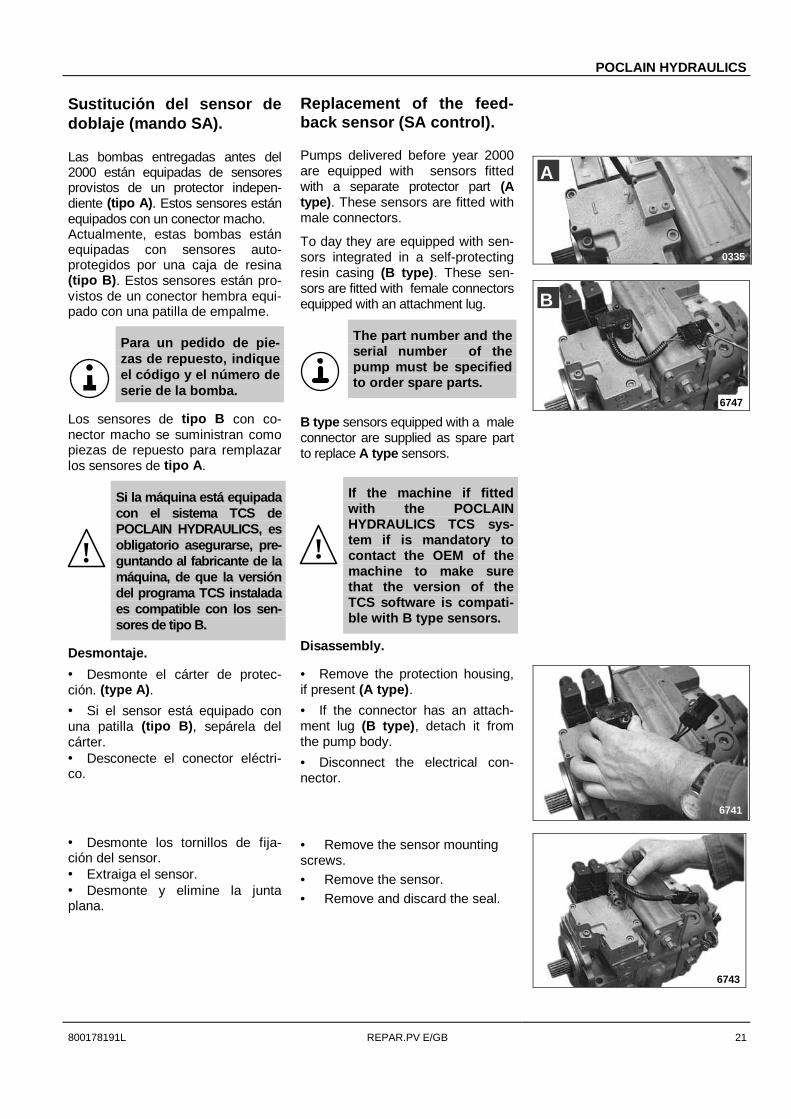
Sustitución del sensor dedoblaje (mando SA).
Las bombas entregadas antes del2000 están equipadas de sensoresprovistos de un protector indepen-diente (tipo A). Estos sensores estánequipados con un conector macho.Actualmente, estas bombas estánequipadas con sensores auto-protegidos por una caja de resina(tipo B). Estos sensores están pro-vistos de un conector hembra equi-pado con una patilla de empalme.
Para un pedido de pie-zas de repuesto, indiqueel código y el número deserie de la bomba.
Los sensores de tipo B con co-nector macho se suministran comopiezas de repuesto para remplazarlos sensores de tipo A.
!
Si la máquina está equipadacon el sistema TCS dePOCLAIN HYDRAULICS, esobligatorio asegurarse, pre-guntando al fabricante de lamáquina, de que la versióndel programa TCS instaladaes compatible con los sen-sores de tipo B.
Desmontaje.
Replacement of the feed-back sensor (SA control).
Pumps delivered before year 2000are equipped with sensors fittedwith a separate protector part (Atype). These sensors are fitted withmale connectors.
To day they are equipped with sen-sors integrated in a self-protectingresin casing (B type). These sen-sors are fitted with female connectorsequipped with an attachment lug.
The part number and theserial number of thepump must be specifiedto order spare parts.
B type sensors equipped with a maleconnector are supplied as spare partto replace A type sensors.
!
If the machine if fittedwith the POCLAINHYDRAULICS TCS sys-tem if is mandatory tocontact the OEM of themachine to make surethat the version of theTCS software is compati-ble with B type sensors.
Disassembly.
• Desmonte el cárter de protec-ción. (type A).
• Si el sensor está equipado conuna patilla (tipo B), sepárela delcárter.• Desconecte el conector eléctri-co.
• Remove the protection housing,if present (A type).
• If the connector has an attach-ment lug (B type), detach it fromthe pump body.
• Disconnect the electrical con-nector.
• Desmonte los tornillos de fija-ción del sensor.• Extraiga el sensor.• Desmonte y elimine la juntaplana.
• Remove the sensor mountingscrews.• Remove the sensor.• Remove and discard the seal.
6743
6741
0335
A
6747
B

POCLAIN HYDRAULICS
22 REPAR.PV E/GB 800178191L
Reinstalación
• Lubrique y monte a continuaciónla junta plana nueva.
• Coloque el árbol del sensor ensu cavidad.• Asegúrese de que hay anillasmetálicas en las pestañas de fija-ción del sensor.
• Oriente el sensor para podermontar los tornillos de fijación.
• Monte los dos tornillos de fija-ción equipados con arandelas pla-nas.• Ajústelos ligeramente para permi-tir la orientación angular del sensor.
!Es imprescindible utilizaruna llave no magnética(suministrada con el kit) paraapretar los tornillos defijación de este sensor.
• Ajuste el punto neutro del sensor:- Aliméntelo a 5 Voltios entre lospasadores A (masa) y C.- Oriéntelo angularmente para ob-tener 2,5 ±0,02 Voltios entre los pa-sadores A y B (ver figura 6751).• Apriete los tornillos de fijaciónmanteniendo la orientación delsensor.
3 ± 0,3 N.m
!
Si la máquina está equipa-da con el sistema TCS dePOCLAIN HYDRAULICS esimprescindible recalibrar lafunción ‘neutra de bombahidráulica’ del controladorTCS.Ver folleto INSTALL TCS ref.677777821K páginas 25 y 30.
Reassembly
• Lubricate, then install a newseal.• Engage the sensor shaft in itshousing.• Make sure of the packing ringposition in the sensor mountingears.• Direct the sensor to be able toinstall the fixing screws.
• Install the both fixing screwsprovided with flat washers.
• Tighten slightly to allow a furtherorientation of the sensor.
!It is compulsory to use anon magnetic key (sup-plied within the kit) totighten the fixing screwsof this sensor.
• Set the sensor neutral point:- Supply voltage 5 Volts betweenpins A (ground) & C.- Orient it to obtain 2,5 ±0,02 Voltsbetween pins A & B (see illustration6751).• Tighten the fixing screws keep-ing the sensor rightly oriented.
[2.2 ± 0.2 lbf.ft]
!
If the machine if fittedwith the POCLAINHYDRAULICS TCS systemit is mandatory to recali-brate the ‘hydraulic pumpneutral’ feature of theTCS controller.See brochure ‘INSTALL TCS’ ref.677777827R pages 25 and 30.
• Reconecte el conector eléctri-co.• Si el sensor está equipado conuna patilla (tipo B), asócielo sobreel cuerpo de bomba con el tornilloprovisto del kit del conector.
• Reconnect the electrical con-nector.• If the connector has an attach-ment lug (B type), attach it onto thepump body with the screw providedwith the connector kit.
6745
6751
67466746
6747

POCLAIN HYDRAULICS
800178191L REPAR.PV E/GB 23
Sustitución de las bobinas(Mando SA)
Se ha introducido un nuevo tipo desolenoide provisto de un conector(tipo B) en enero 2000. No es in-tercambiable con la versión anterior(tipo A) que se sigue suministrandocomo pieza de repuesto..
Para un pedido de pie-zas de repuesto, indiqueel código del artículo, elnúmero de serie de labomba
Desmontaje.
Replacement of the sole-noid (SA control).
A new type of solenoid equippedwith a connector was introduced inJanuary 2000 (B type). It is notinterchangeable with the previousversion (A type) that is still suppliedas spare part.
The part number and theserial number of thepump must be specifiedto order spare parts.
Disassembly.
• Si los solenoides están equipa-dos de conectores (tipo B), aflojelos tornillos de fijación situados enla parte superior y desconecte losdos conectores.• En cualquier caso (tipos A y B)retire las tuercas situadas en los ex-tremos de los solenoides, las aran-delas de soporte y elimine las juntastóricas.• Extraiga los solenoides.
• If the solenoids are equippedwith connectors (B type), loosenthe attaching screws located at thetop then disconnect the twoconnectors.• In all cases ( A & B types) re-move the nuts located at the end ofthe solenoids, the thrust washersand discard the O-rings.
• Extract the solenoids.
Reinstalación
• Monte los solenoides y orién-telos (ver ilustraciones).
Si los solenoides tienenpatillas (tipo A), coló-quelas en el orificio deindexado del mando.
• Lubrique e instale las juntastóricas nuevas en las arandelas desoporte.• Monte las arandelas de soporte.• Monte y apriete las tuercas defijación manualmente.
• Si los solenoides están equipa-dos con conectores (tipo B):- Retire las caperuzas de protec-
ción que protegen los guarda-cabos,
- Reconecte los conectores delos solenoides,
- Apriete los tornillos de fijaciónde los conectores.
Reassembly
• Install and orient the solenoids(see illustrations).
If the solenoids have in-dexing pins (A type) lo-cate the pins in the corre-sponding holes of thecontrol.
• Lubricate then install new O-rings into the thrust washers.
• Install the thrust washers.• Install and tighten the mountingnuts manually.
• If the solenoids are equippedwith connectors ( B type):- Remove the caps protecting the
pins,- Reconnect the solenoids con-
nectors.- Screw and tighten the connec-
tors fixing screws.
0333
A
B
6750
6749
B
6748
0335
A

POCLAIN HYDRAULICS
24 REPAR.PV E/GB 800178191L
Herramientas standard Standard Tooling
Llave hexagonal para tornillo 9 / 16" Hex key (Allen) 9 / 16"
5 / 8" 5 / 8"
5 / 16" 5 / 16"
1 / 4" 1 / 4"
Llave con casquillo 7 / 16" End wrench 7 / 16"
9 / 16" 9 / 16"
1 / 2" 1 / 2"
3 / 4" 3 / 4"
11 / 16" 11 / 16"
1" 1"
5 / 16" 5 / 16"
1 1/4" 1 1/4"
Pinza con anilla de retención interior Internal retaining ring pliers
Pinza con anilla de retención exterior External retaining ring pliers
Llave dinamométrica ................................ 200 N.m Torque wrench ................................... 150 lbf.ft
Martillo minero plástico Hammer (soft face)

POCLAIN HYDRAULICS
800178191L REPAR.PV E/GB 25
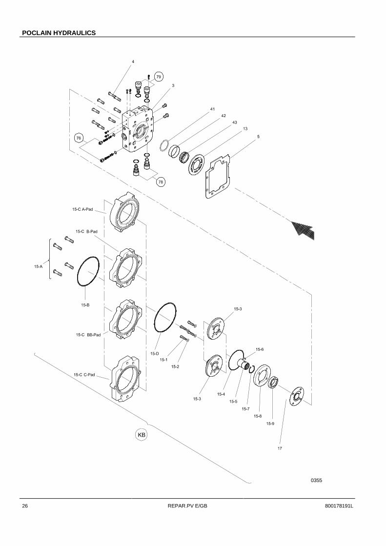
Piezas de repuestoPara un pedido de piezas de repuesto, indique el códi-go del artículo, el numéro de serie de la bomba y elnuméro de orden de la pieza listados a continuación.
Número Designación
O 76 válvulas de anulación de caudalO 78 válvula de seguridad equipada (Orificio A)
O 79 válvula de seguridad equipada (Orificio B)
O 85 taquímetro equipado (opcional)
O K1 junta de eje equipada116 retén117 anillo de cierre118 tirante
O K2 Kit de retroalimentación88 Sensor de retroalimentación equipado
(cable, conector y tornillería incluidos)92 eje de retroalimentación93 junta tórica94 casquillo de guidaje
O K3 Mando equipado6 Mando7 junta plana8 tornillo9 tornillo
O KA Kit mando equipadoK2 sensor equipadoK3 Mando equipado70 palanca de retroalimentación
O KB Kit bomba de prellenado15 - A tornillo15 - B junta tórica15 - C brida de conexión15 - D junta tórica15 - 1 tornillo15 - 2 arandelas15 - 3 tapa bomba de prellenado15 - 4 junta tórica15 - 5 árbol bomba de prellenado15 - 6 clavija15 - 7 arandela de retención15 - 8 leva excéntrica15 - 9 gerotor17 placa de alimentación
Leyenda:
O Subconjunto suministrado en kit.O Pieza suministrada por separado Pieza no suministrada por separado (kit)
Spare partsFor each order indicate part number and serial numberof the hydraulic pump and part item number as shownbelow.
Item Description
O 76 Pressure override valves (POR){ 78 Relief valve POR (A port)
{ 79 Relief valve POR (B port)
{ 85 Speed sensor (optional)
} K1 Shaft seal kit116 Shaft seal117 Retaining ring118 Spacer
} K2 Feedback kit88 Feedback sensor kit
(including wire, connector & screws)92 Feedback shaft93 O-ring94 Hollow dowel
} K3 Control valve kit6 Control valve7 Gasket8 Screw9 Screw
} KA Control valve assembly kitK2 Potentiometer kitK3 Control valve kit70 Control link
} KB Boost (charge) pump kit15 - A Screw15 - B O-ring15 - C Link pad15 - D O-ring15 - 1 Screw15 - 2 Spacer15 - 3 Boost pump cover15 - 4 O-ring15 - 5 Boost pump shaft15 - 6 Shaft key15 - 7 Retain ring15 - 8 Cam15 - 9 Gerotor17 Valve plate
Key:
} Sub assembly kit{ Part supplied separately Part not supplied separately (kit
POCLAIN HYDRAULICS
26 REPAR.PV E/GB 800178191L
0355

POCLAIN HYDRAULICS
800178191L REPAR.PV E/GB 27
0356

China
POCLAIN HYDRAULICS BEIJING rep. officeUnit A0808, Hui Bin OfficiesNo.8 Beichendong St.BEIJING 100101CHINATel.: 86 10 6499 3988Fax: 86 10 6499 3979e-mail: [email protected]
España & Portugal
POCLAIN HYDRAULICS SPAIN S.L.Gran Via Carlos III no84 – 1o 3a
08028 BARCELONAESPAÑATel.: 349 3 491 28 95Fax: 349 3 490 21 79e-mail: [email protected]
Ceská Republika
POCLAIN HYDRAULICS SROKšírova 18661900 BRNOCESKÁ REPUBLIKATel.: 420 5 43217830Fax: 420 5 43217818e-mail: [email protected]
France
POCLAIN HYDRAULICS France SASB.P. 10660411 VERBERIE CEDEXFRANCETel.: 33 3 44 40 77 77Fax: 33 3 44 40 77 91e-mail: [email protected]
Deutschland
POCLAIN HYDRAULICS GMBHBergstrasse 10664319 PFUNGSTADTDEUTSCHLANDTel.: 49 6157 9474 0Fax: 49 6157 9474 74e-mail: [email protected]
Japan
POCLAIN HYDRAULICS KK5-4-6 KugenumashinmeFUJISAWA 251JAPANTel: 81 466 50 4400Fax: 81 466 50 4422e-mail: [email protected]
Italia
POCLAIN HYDRAULICS SRLVia Svizzera 4/A41012 CARPI (MODENA)ITALIA
Tel.: 390 59 64 22 44Fax: 390 59 64 20 44e-mail: [email protected]
United Kingdom
POCLAIN HYDRAULICS LTDNene Valley Business ParkOundlePETERBOROUGH, Cambs PE8 4HNENGLANDTel.: 44 1832 273773Fax: 44 1832 274990e-mail: [email protected]
Nederland
POCLAIN HYDRAULICS BENELUX BVPenningweg 32C4879 AM ETTEN-LEURNEDERLAND
Tel.: 31 76 5021152Fax: 31 76 5012279e-mail: [email protected]
USA
POCLAIN HYDRAULICS INC.7900 Durand AvenueP.O. BOX 801STURTEVANT, WI 53177USATel.: 1 262 554 6739Fax: 1 262 554 4860e-mail: [email protected]
POCLAIN HYDRAULICS INDUSTRIEB.P. 106
60411 VERBERIE CEDEX - FranceTel.: 33 3 44 40 77 77Fax: 33 3 44 40 77 99e-mail: [email protected]
www.poclain-hydraulics.com
S.A.S. au capital de 85 124 000 Francs Siège social: Route de Saint Sauveur VERBERIE (OISE) R.C.S. Senlis B 414 781 823Siret 414 781 823 00011