BNT Virtual Fabric 10Gb Switch Module: Installation...
68
BNT Virtual Fabric 10Gb Switch Module for IBM BladeCenter Installation Guide
-
Upload
nguyenduong -
Category
Documents
-
view
227 -
download
0
Transcript of BNT Virtual Fabric 10Gb Switch Module: Installation...
BNT Virtual Fabric 10Gb Switch Module for IBMBladeCenter
Installation Guide
���


BNT Virtual Fabric 10Gb Switch Module for IBMBladeCenter
Installation Guide
���

Note: Before using this information and the product it supports, read the Warranty Information document and Appendix B,“Notices,” on page 45; and read the IBM Safety Information and the IBM Systems Environmental Notices and User Guide on the IBMDocumentation CD
Second Edition (November 2010)
© Copyright IBM Corporation 2009, 2010.US Government Users Restricted Rights – Use, duplication or disclosure restricted by GSA ADP Schedule Contractwith IBM Corp.
Contents
Safety . . . . . . . . . . . . . . . v
Chapter 1. The BNT Virtual Fabric 10GbSwitch Module . . . . . . . . . . . . 1Specifications . . . . . . . . . . . . . . 3Related documentation . . . . . . . . . . . 3Inventory checklist . . . . . . . . . . . . 4Notices and statements in this document . . . . . 4Major components of the switch module . . . . . 5
Chapter 2. Installing and replacing aswitch module . . . . . . . . . . . . 7Installation guidelines . . . . . . . . . . . 8
System reliability guidelines . . . . . . . . 8Handling static-sensitive devices. . . . . . . 9
Installing a switch module . . . . . . . . . 10Removing or replacing a switch module . . . . . 12
Chapter 3. Installing and removing a 10Gb SFP+ module . . . . . . . . . . 15Handling an SFP+ module . . . . . . . . . 15Installing an SFP+ module . . . . . . . . . 17Removing an SFP+ module . . . . . . . . . 18
Chapter 4. Cabling the switch moduleand the SFP+ module . . . . . . . . 19Connecting the serial console cable . . . . . . 19Disconnecting the serial console cable . . . . . 19Connecting the SFP+ module cable . . . . . . 20Disconnecting the SFP+ module cable . . . . . 20Connecting the RJ-45 cable . . . . . . . . . 21Disconnecting the RJ-45 cable . . . . . . . . 21
Chapter 5. Information panels, LEDs,and external ports . . . . . . . . . . 23Information panel . . . . . . . . . . . . 23Information LEDs . . . . . . . . . . . . 24
Switch-module status LEDs . . . . . . . . 25Port status LEDs. . . . . . . . . . . . 25
Chapter 6. Configuring the switchmodule . . . . . . . . . . . . . . 27Establishing a TCP/IP session through themanagement module . . . . . . . . . . . 28Enabling management through external ports . . . 29Configuring the switch module through the Telnetinterface . . . . . . . . . . . . . . . 30
Connecting to the switch module . . . . . . 30Accessing the main menu . . . . . . . . 30
Configuring the switch module through theserial-port interface . . . . . . . . . . . . 31Configuring the switch module through theswitch-module browser-based interface . . . . . 32
Initial configuration . . . . . . . . . . . 33Logging in to the switch module . . . . . . . 33
Chapter 7. Updating the software . . . 35Determining the level of switch-module software . . 35Obtaining the latest level of switch software . . . 35Upgrading the switch-module software . . . . . 36Resetting and restarting the switch module . . . . 37
Chapter 8. Parts listing . . . . . . . . 39
Chapter 9. Solving problems . . . . . 41Running POST . . . . . . . . . . . . . 41POST errors . . . . . . . . . . . . . . 41
Appendix A. Getting help and technicalassistance . . . . . . . . . . . . . 43Before you call . . . . . . . . . . . . . 43Using the documentation . . . . . . . . . . 43Getting help and information from the World WideWeb . . . . . . . . . . . . . . . . . 44Software service and support . . . . . . . . 44Hardware service and support . . . . . . . . 44IBM Taiwan product service . . . . . . . . . 44
Appendix B. Notices . . . . . . . . . 45Trademarks . . . . . . . . . . . . . . 45Important notes . . . . . . . . . . . . . 46Electronic emission notices . . . . . . . . . 47
Federal Communications Commission (FCC)statement . . . . . . . . . . . . . . 47Industry Canada Class A emission compliancestatement . . . . . . . . . . . . . . 47Avis de conformité à la réglementationd'Industrie Canada . . . . . . . . . . . 47Australia and New Zealand Class A statement . 47United Kingdom telecommunications safetyrequirement . . . . . . . . . . . . . 47European Union EMC Directive conformancestatement . . . . . . . . . . . . . . 47Taiwanese Class A warning statement . . . . 48Germany Electromagnetic Compatibility Directive 48
Deutschland: Einhaltung des Gesetzes überdie elektromagnetische Verträglichkeit vonGeräten. . . . . . . . . . . . . . 49Zulassungsbescheinigung laut dem DeutschenGesetz über die elektromagnetischeVerträglichkeit von Geräten (EMVG) (bzw. derEMC EG Richtlinie 2004/108/EG) für Geräteder Klasse A . . . . . . . . . . . . 49
People's Republic of China Class A warningstatement . . . . . . . . . . . . . . 49Japanese Voluntary Control Council forInterference (VCCI) statement . . . . . . . 49
© Copyright IBM Corp. 2009, 2010 iii

Korean Class A warning statement . . . . . 49
Index . . . . . . . . . . . . . . . 51
iv BNT Virtual Fabric 10Gb Switch Module: Installation Guide
Safety
Before installing this product, read the Safety Information.
Antes de instalar este produto, leia as Informações de Segurança.
Pred instalací tohoto produktu si prectete prírucku bezpecnostních instrukcí.
Læs sikkerhedsforskrifterne, før du installerer dette produkt.
Lees voordat u dit product installeert eerst de veiligheidsvoorschriften.
Ennen kuin asennat tämän tuotteen, lue turvaohjeet kohdasta Safety Information.
Avant d'installer ce produit, lisez les consignes de sécurité.
Vor der Installation dieses Produkts die Sicherheitshinweise lesen.
Prima di installare questo prodotto, leggere le Informazioni sulla Sicurezza.
Les sikkerhetsinformasjonen (Safety Information) før du installerer dette produktet.
Antes de instalar este produto, leia as Informações sobre Segurança.
Antes de instalar este producto, lea la información de seguridad.
Läs säkerhetsinformationen innan du installerar den här produkten.
© Copyright IBM Corp. 2009, 2010 v

Important:
Each caution and danger statement in this document is labeled with anumber. This number is used to cross reference an English-languagecaution or danger statement with translated versions of the caution ordanger statement in the Safety Information document.
For example, if a caution statement is labeled “Statement 1,”translations for that caution statement are in the Safety Informationdocument under “Statement 1.”
Be sure to read all caution and danger statements in this documentbefore you perform the procedures. Read any additional safetyinformation that comes with the server or optional device before youinstall the device.
This device is intended for use with UL Listed IBM BladeCenters.
vi BNT Virtual Fabric 10Gb Switch Module: Installation Guide
Statement 1:
DANGER
Electrical current from power, telephone, and communication cables ishazardous.
To avoid a shock hazard:
v Do not connect or disconnect any cables or perform installation,maintenance, or reconfiguration of this product during an electrical storm.
v Connect all power cords to a properly wired and grounded electrical outlet.
v Connect to properly wired outlets any equipment that will be attached tothis product.
v When possible, use one hand only to connect or disconnect signal cables.
v Never turn on any equipment when there is evidence of fire, water, orstructural damage.
v Disconnect the attached power cords, telecommunications systems,networks, and modems before you open the device covers, unlessinstructed otherwise in the installation and configuration procedures.
v Connect and disconnect cables as described in the following table wheninstalling, moving, or opening covers on this product or attached devices.
To Connect: To Disconnect:
1. Turn everything OFF.
2. First, attach all cables to devices.
3. Attach signal cables to connectors.
4. Attach power cords to outlet.
5. Turn device ON.
1. Turn everything OFF.
2. First, remove power cords from outlet.
3. Remove signal cables from connectors.
4. Remove all cables from devices.
Safety vii
Statement 3:
CAUTION:When laser products (such as CD-ROMs, DVD drives, fiber optic devices, ortransmitters) are installed, note the following:
DANGER
Some laser products contain an embedded Class 3A or Class 3B laser diode.Note the following.
Laser radiation when open. Do not stare into the beam, do not view directlywith optical instruments, and avoid direct exposure to the beam.
Class 1 Laser ProductLaser Klasse 1Laser Klass 1Luokan 1 LaserlaiteAppareil A Laser de Classe 1`
viii BNT Virtual Fabric 10Gb Switch Module: Installation Guide
Statement 8:
CAUTION:Never remove the cover on a power supply or any part that has the followinglabel attached.
Hazardous voltage, current, and energy levels are present inside any componentthat has this label attached. There are no serviceable parts inside thesecomponents. If you suspect a problem with one of these parts, contact a servicetechnician.
Safety ix

x BNT Virtual Fabric 10Gb Switch Module: Installation Guide
Chapter 1. The BNT Virtual Fabric 10Gb Switch Module
The BNT Virtual Fabric 10Gb Switch Module for IBM BladeCenter is a high-speedEthernet component that is installed into a BladeCenter® unit that supportshigh-speed I/O modules.
This Installation Guide contains instructions for and information about:v Setting up and installing or replacing the BNT Virtual Fabric 10Gb Switch
Module for IBM BladeCenterv Installing and removing optional devices in the switch modulev Using the information panel, LEDs, and external ports on the switch modulev Cabling the switch module and its optional devicesv Configuring the switch modulev Updating the switch-module softwarev Solving problems with the switch module
For installation instructions, see Chapter 2, “Installing and replacing a switchmodule,” on page 7 and Chapter 3, “Installing and removing a 10 Gb SFP+module,” on page 15. For additional information about switch modules and otherBladeCenter components, see the BladeCenter documentation that comes withthese devices.
To support each BNT Virtual Fabric 10Gb Switch Module that you install in theBladeCenter unit, you must also install a compatible high-speed Ethernetexpansion card (also known as an Ethernet I/O card) in each blade server that youwant to communicate with the switch module. In this environment, the expansioncard operates as a host channel adapter (HCA). For additional information, seeChapter 2, “Installing and replacing a switch module,” on page 7 and theinstallation information for the Ethernet expansion card.
For information about the types of compatible expansion cards for the blade server,contact your IBM marketing representative or authorized reseller. For a list ofsupported optional devices for the blade server, see http://www.ibm.com/servers/eserver/serverproven/compat/us/. For details about compatible expansion cardinstallation, configuration, and use, see the documentation that comes with theadapter.
You can obtain up-to-date information about the BNT 10-Port 10Gb EthernetSwitch Module for IBM® BladeCenter at http://www.ibm.com/systems/bladecenter/.
Notes:
1. Throughout this document, the BNT Virtual Fabric 10Gb Switch Module forIBM BladeCenter is referred to as the high-speed switch module, the HSSM, theswitch module, or the I/O module.
2. Unless otherwise stated, references to the BladeCenter unit apply to allBladeCenter units that support high-speed I/O modules, such as theBladeCenter H unit.
3. Changes are made periodically to the IBM Web site. Procedures for locatingfirmware and documentation might vary slightly from what is described in thisdocument.
© Copyright IBM Corp. 2009, 2010 1
4. The illustrations in this document might differ slightly from your hardware.5. The screens that are described or referenced in this document might differ
slightly from the screens that are displayed by your system. Screen contentvaries according to the type of BladeCenter unit and the firmware versions andoptions that are installed.
6. Unless otherwise stated, references to the management module apply only tothe BladeCenter Advanced Management Module, which is the only type ofmanagement module that supports the switch module.
The switch module has the following components:v Fourteen internal 10 Gb ports, one connected to each of the blade servers in the
BladeCenter unitv Two internal 1 Gb ports to connect to the management modulev Ten external 10 Gb user ports for connecting small-form-factor pluggable (SFP+)
modulesv One external 1 Gb Ethernet portv One external RS-232 serial port for management use
You can manage and configure the switch module through multiple interfaces:v A Telnet connection to the embedded command-line interface (CLI)v A terminal emulation program connection to the serial-port interfacev A Web browser-based interface (BBI) connection to the switch module
For more information, see Chapter 6, “Configuring the switch module,” on page27.
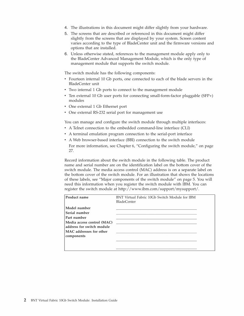
Record information about the switch module in the following table. The productname and serial number are on the identification label on the bottom cover of theswitch module. The media access control (MAC) address is on a separate label onthe bottom cover of the switch module. For an illustration that shows the locationsof these labels, see “Major components of the switch module” on page 5. You willneed this information when you register the switch module with IBM. You canregister the switch module at http://www.ibm.com/support/mysupport/.
Product name BNT Virtual Fabric 10Gb Switch Module for IBMBladeCenter
Model number _____________________________________________Serial number _____________________________________________Part number _____________________________________________Media access control (MAC)address for switch module
_____________________________________________
MAC addresses for othercomponents
_____________________________________________
_____________________________________________
_____________________________________________
2 BNT Virtual Fabric 10Gb Switch Module: Installation Guide
SpecificationsFor detailed information about the switch-module hardware and software features,specifications, and standards, see the switch module Application Guide.
Related documentationThis Installation Guide contains setup and installation instructions for the switchmodule and general information about the switch module, including gettingstarted, how to configure the switch module, and how to get help.
Notes:
v The most recent versions of this Installation Guide and all other BladeCenterdocumentation are at http://www.ibm.com/systems/support/
v Depending on your blade server model, additional documentation might beincluded on the IBM BladeCenter Documentation CD for the IBM BladeCenterunit.
The following related documentation is available at http://www.ibm.com/systems/support/:v BladeCenter Problem Determination and Service Guide
v BladeCenter Hardware Maintenance Manual and Troubleshooting Guide
v BladeCenter Advanced Management Module Installation Guide or BladeCenter TAdvanced Management Module Installation Guide
v IBM BladeCenter Advanced Management Module Command-Line Interface ReferenceGuide
v IBM BladeCenter Advanced Management Module User’s Guide
v Installation and User’s Guide for the BladeCenter unitv Safety Information
v Broadcom 10 Gb 2-Port and 4-Port Ethernet Expansion Cards (CFFh) for IBMBladeCenter Installation and User's Guide
v BNT Application Guide for the switch modulev BNT Browser Based Interface Quick Guide for the switch modulev BNT Command Reference for the switch modulev BNT ISCLI Reference for the switch module
See the IBM Configuration and Options Guide for information about which SFP+module and cable are required to connect the switch module to other networkdevices. This document is available in both HTML and Portable Document Format(PDF) from http://www.ibm.com/servers/eserver/xseries/cog/.
For more information about documentation requirements, see “Using thedocumentation” on page 43.
Chapter 1. The BNT Virtual Fabric 10Gb Switch Module 3
Inventory checklistMake sure that the shipping carton contains the following items:v One switch modulev The BNT Virtual Fabric 10Gb Switch Module for IBM BladeCenter Installation Guide
(this document)v One serial console cablev One filler modulev Safety flyerv End User License Agreement
If any of these items are missing or damaged, contact your authorized reseller forreplacement.
Notices and statements in this documentThe caution and danger statements in this document are also in the multilingualSafety Information document, which is on the IBM BladeCenter Documentation CD forthe BladeCenter unit. Each statement is numbered for reference to thecorresponding statement in your language in the Safety Information document.
The following notices and statements are used in this document:v Note: These notices provide important tips, guidance, or advice.v Important: These notices provide information or advice that might help you
avoid inconvenient or problem situations.v Attention: These notices indicate potential damage to programs, devices, or data.
An attention notice is placed just before the instruction or situation in whichdamage could occur.
v Caution: These statements indicate situations that can be potentially hazardousto you. A caution statement is placed just before the description of a potentiallyhazardous procedure step or situation.
v Danger: These statements indicate situations that can be potentially lethal orextremely hazardous to you. A danger statement is placed just before thedescription of a potentially lethal or extremely hazardous procedure step orsituation.
4 BNT Virtual Fabric 10Gb Switch Module: Installation Guide
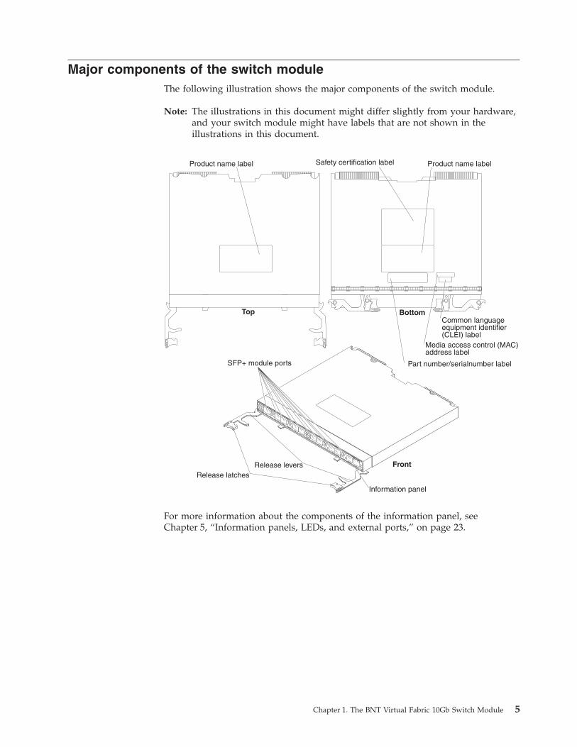
Major components of the switch moduleThe following illustration shows the major components of the switch module.
Note: The illustrations in this document might differ slightly from your hardware,and your switch module might have labels that are not shown in theillustrations in this document.
For more information about the components of the information panel, seeChapter 5, “Information panels, LEDs, and external ports,” on page 23.
Chapter 1. The BNT Virtual Fabric 10Gb Switch Module 5

6 BNT Virtual Fabric 10Gb Switch Module: Installation Guide
Chapter 2. Installing and replacing a switch module
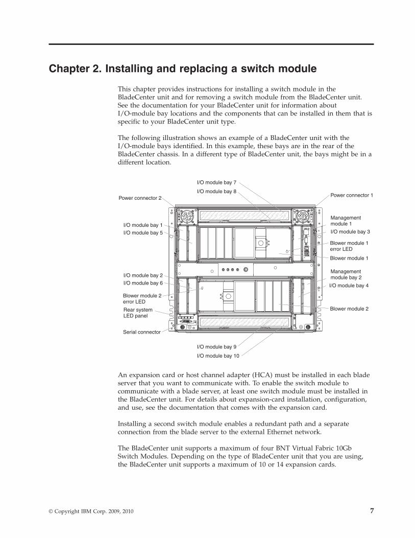
This chapter provides instructions for installing a switch module in theBladeCenter unit and for removing a switch module from the BladeCenter unit.See the documentation for your BladeCenter unit for information aboutI/O-module bay locations and the components that can be installed in them that isspecific to your BladeCenter unit type.
The following illustration shows an example of a BladeCenter unit with theI/O-module bays identified. In this example, these bays are in the rear of theBladeCenter chassis. In a different type of BladeCenter unit, the bays might be in adifferent location.
I/O module bay 4
I/O module bay 3
I/O module bay 2
I/O module bay 6
I/O module bay 1
I/O module bay 7
I/O module bay 9
I/O module bay 8
I/O module bay 10
I/O module bay 5
Power connector 2 Power connector 1
Managementmodule 1
Managementmodule bay 2
Blower module 1
Blower module 1error LED
Blower module 2error LED
Blower module 2Rear systemLED panel
Serial connector
An expansion card or host channel adapter (HCA) must be installed in each bladeserver that you want to communicate with. To enable the switch module tocommunicate with a blade server, at least one switch module must be installed inthe BladeCenter unit. For details about expansion-card installation, configuration,and use, see the documentation that comes with the expansion card.
Installing a second switch module enables a redundant path and a separateconnection from the blade server to the external Ethernet network.
The BladeCenter unit supports a maximum of four BNT Virtual Fabric 10GbSwitch Modules. Depending on the type of BladeCenter unit that you are using,the BladeCenter unit supports a maximum of 10 or 14 expansion cards.
© Copyright IBM Corp. 2009, 2010 7
Notes:
v The blade servers or BladeCenter units that are described or shown in thisdocument might be different from your blade server or BladeCenter unit. Foradditional information, see the documentation that comes with your blade serveror BladeCenter unit.
v If you are installing only one switch module, use I/O-module bay 7 or 9.v When the switch module is installed in a BladeCenter unit, the internal ports
operate at 10 Gbps. The external ports can operate at 10 Gbps or 1 Gbps,depending on the SFP module type.
v Configuration requirements for the switch module and the BladeCenter unitmight vary. You can obtain up-to-date information about the switch module andthe BladeCenter unit at http://www.ibm.com/systems/bladecenter/.
Installation guidelinesBefore you install the switch module in the BladeCenter unit, read the followinginformation:v Read the safety information that begins on page v, “Handling static-sensitive
devices” on page 9, and the safety statements in the BladeCenter unitdocumentation. This information will help you work safely.
v Observe good housekeeping in the area where you are working. Place removedcovers and other parts in a safe place.
v Blue on a component indicates touch points, where you can grip the componentto remove it from or install it in the blade server or BladeCenter unit, open orclose a latch, and so on.
v Orange on a component or an orange label on or near a component on theswitch module, blade server, or BladeCenter unit indicates that the componentcan be hot-swapped, which means that if the BladeCenter unit and operatingsystem support hot-swap capability, you can remove or install the componentwhile the BladeCenter unit is running. (Orange can also indicate touch points onhot-swap components.) See the instructions for removing or installing a specifichot-swap component for any additional procedures that you might have toperform before you remove or install the component.
v You do not have to turn off the BladeCenter unit to install or replace any of thehot-swap modules on the front or rear of the BladeCenter unit.
v When you install a switch module in the BladeCenter unit, you must also installa compatible I/O expansion card in the blade server to support the switchmodule.
v When you are finished working on the blade server or BladeCenter unit,reinstall all safety shields, guards, labels, and ground wires.
v For a list of supported optional devices for the BladeCenter unit and other IBMproducts, see http://www.ibm.com/servers/eserver/serverproven/compat/us/.
System reliability guidelinesTo help ensure proper cooling, performance, and system reliability, make sure thatthe following requirements are met:v Each of the module bays on the rear of the BladeCenter unit contains either a
module or a filler module.v A removed hot-swap module is replaced with an identical module or filler
module within 1 minute of removal.v A removed hot-swap blade server is replaced with another blade server or filler
blade within 1 minute of removal.
8 BNT Virtual Fabric 10Gb Switch Module: Installation Guide
v The ventilation areas on the sides of the blade server are not blocked.v You have followed the reliability guidelines in the documentation that comes
with the BladeCenter unit.
Cable requirements for the switch module are described in the IBM Configurationand Options Guide at http://www.ibm.com/servers/eserver/xseries/cog/. See thedocumentation that comes with the blade server for cable-routing information.
Handling static-sensitive devices
Attention: Static electricity can damage the BladeCenter unit and other electronicdevices. To avoid damage, keep static-sensitive devices in their static-protectivepackages until you are ready to install them.
To reduce the possibility of electrostatic discharge, observe the followingprecautions:v Limit your movement. Movement can cause static electricity to build up around
you.v Handle the device carefully, holding it by its edges or its frame.v Do not touch solder joints, pins, or exposed printed circuitry.v Do not leave the device where others can handle and damage it.v While the device is still in its static-protective package, touch it to an unpainted
metal surface of the BladeCenter unit chassis or an unpainted metal surface onany other grounded rack component in the rack that you are installing thedevice in for at least 2 seconds. This drains static electricity from the packageand from your body.
v Remove the device from its package and install it directly into the BladeCenterunit without setting down the device. If it is necessary to set down the device,put it back into its static-protective package. Do not place the device on theBladeCenter unit or on a metal surface.
v Take additional care when you handle devices during cold weather. Heatingreduces indoor humidity and increases static electricity.
v Some types of BladeCenter units come with electrostatic discharge (ESD)connectors. If the BladeCenter unit is equipped with an ESD connector, see thedocumentation that comes with the BladeCenter unit for using the ESDconnector.
Chapter 2. Installing and replacing a switch module 9

Installing a switch module
Note: The following illustration shows how to install a switch module in a Type8852 BladeCenter unit. The appearance of your BladeCenter unit might bedifferent; see the documentation for your BladeCenter unit for additionalinformation.
To install a switch module, complete the following steps:
1. Read the safety information that begins on page v and “Installationguidelines” on page 8.
2. Select I/O-module bay in which to install the switch module.
Note: For details about I/O-module bay requirements and bay locations, seethe documentation for the BladeCenter unit and blade servers.
3. Remove the filler module from the selected bay. Store the filler module forfuture use.
4. If you have not already done so, touch the static-protective package thatcontains the switch module to an unpainted metal surface of the BladeCenterunit or an unpainted metal surface on any other grounded rack-component forat least 2 seconds.
5. If the removed filler module (from step 3) occupied two bays:v Remove the single-high filler module from its static-protective package.v Install the single-high filler module into the unused bay.
6. Remove the switch module from its static-protective package.7. Make sure that the release levers on the switch module are in the open
position (perpendicular to the module).For specific instructions for installing a switch module in the BladeCenterunit, see the documentation that comes with the BladeCenter unit.
8. Slide the switch module into the applicable I/O-module bay until it stops.9. Push the release levers on the front of the switch module to the closed
position. After you insert and lock the switch module, it is turned on, and apower-on self-test (POST) occurs to verify that the switch module is operatingcorrectly.
10 BNT Virtual Fabric 10Gb Switch Module: Installation Guide
Notes:
a. The switch module takes approximately 60 seconds to complete the POST.When the switch module is turned on, an LED test occurs. All LEDs are litand remain lit during POST; then, all the LEDs except the OK LED turnoff. This indicates normal POST results.
b. To maintain proper airflow, make sure that the ventilation holes on thefront of the switch module are not blocked.
10. Make sure that the LEDs on the switch module indicate that it is operatingcorrectly (see “Information LEDs” on page 24).
11. If you have another switch module to install, repeat step 3 on page 10 throughstep 10; otherwise, go to the next step.
12. Install the SFP+ modules in the switch module. For information andinstructions, see Chapter 3, “Installing and removing a 10 Gb SFP+ module,”on page 15 and the documentation that comes with the SFP+ module.
13. Attach any cables that are required by the switch module. For additionalinformation about cabling the switch module, see Chapter 4, “Cabling theswitch module and the SFP+ module,” on page 19, the documentation thatcomes with the cables, and the optional network devices to which the cableshave been connected. For the locations of the connectors on the BladeCenterunit, see the documentation that comes with the BladeCenter unit. Then,continue with the next step.
14. Make sure that the external ports on the switch module are enabled throughone of the management-module interfaces, such as the Web-based interface orthe CLI.
Chapter 2. Installing and replacing a switch module 11
Removing or replacing a switch module
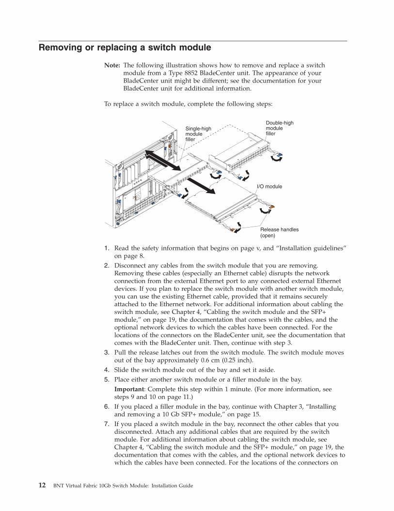
Note: The following illustration shows how to remove and replace a switchmodule from a Type 8852 BladeCenter unit. The appearance of yourBladeCenter unit might be different; see the documentation for yourBladeCenter unit for additional information.
To replace a switch module, complete the following steps:
1. Read the safety information that begins on page v, and “Installation guidelines”on page 8.
2. Disconnect any cables from the switch module that you are removing.Removing these cables (especially an Ethernet cable) disrupts the networkconnection from the external Ethernet port to any connected external Ethernetdevices. If you plan to replace the switch module with another switch module,you can use the existing Ethernet cable, provided that it remains securelyattached to the Ethernet network. For additional information about cabling theswitch module, see Chapter 4, “Cabling the switch module and the SFP+module,” on page 19, the documentation that comes with the cables, and theoptional network devices to which the cables have been connected. For thelocations of the connectors on the BladeCenter unit, see the documentation thatcomes with the BladeCenter unit. Then, continue with step 3.
3. Pull the release latches out from the switch module. The switch module movesout of the bay approximately 0.6 cm (0.25 inch).
4. Slide the switch module out of the bay and set it aside.5. Place either another switch module or a filler module in the bay.
Important: Complete this step within 1 minute. (For more information, seesteps 9 and 10 on page 11.)
6. If you placed a filler module in the bay, continue with Chapter 3, “Installingand removing a 10 Gb SFP+ module,” on page 15.
7. If you placed a switch module in the bay, reconnect the other cables that youdisconnected. Attach any additional cables that are required by the switchmodule. For additional information about cabling the switch module, seeChapter 4, “Cabling the switch module and the SFP+ module,” on page 19, thedocumentation that comes with the cables, and the optional network devices towhich the cables have been connected. For the locations of the connectors on
12 BNT Virtual Fabric 10Gb Switch Module: Installation Guide

the BladeCenter unit, see the documentation that comes with the BladeCenterunit. Then, continue with Chapter 3, “Installing and removing a 10 Gb SFP+module,” on page 15.
Chapter 2. Installing and replacing a switch module 13

14 BNT Virtual Fabric 10Gb Switch Module: Installation Guide
Chapter 3. Installing and removing a 10 Gb SFP+ module
The switch module supports both the 10 Gb small-form-factor pluggable (SFP+)module and the 1 Gb small-form-factor pluggable (SFP) module. The SFP+ andSFP modules are laser products that convert electrical signals to optical signals.
For additional information about the location of the switch module, the networkinterface requirements, and expansion options, see the documentation for yourBladeCenter unit.
Notes:
1. The illustrations in this document might differ slightly from your hardware.2. While the information in this section describes the 10 Gb small-form-factor
pluggable (SFP+) module, it also applies to the 1 Gb small-form-factorpluggable (SFP) module.
3. The switch module also supports MSA-compliant copper direct-attach cables(DAC), up to 7 m (23 ft) in length.
Handling an SFP+ moduleBefore you install an SFP+ module, read the following information:v The module housing of the SFP+ has an integral guide key that is designed to
prevent you from inserting the module incorrectly.v Use minimal pressure when you insert the module into the port. Forcing the
module into the port can cause damage to the module or the module port.v You can insert or remove the module while the BladeCenter unit is turned on.v You must first insert the module into the port before you can connect the cables.v You must remove the cable from the SFP+ module before you remove the SFP+
module from the switch module.
© Copyright IBM Corp. 2009, 2010 15
Statement 3:
CAUTION:When laser products (such as CD-ROMs, DVD drives, fiber optic devices, ortransmitters) are installed, note the following:
– Do not remove the covers. Removing the covers of the laser product couldresult in exposure to hazardous laser radiation. There are no serviceableparts inside the device.
– Use of controls or adjustments or performance of procedures other thanthose specified herein might result in hazardous radiation exposure.
DANGER
Some laser products contain an embedded Class 3A or Class 3B laser diode.Note the following.
Laser radiation when open. Do not stare into the beam, do not viewdirectly with optical instruments, and avoid direct exposure to the beam.
Class 1 Laser ProductLaser Klasse 1Laser Klass 1Luokan 1 LaserlaiteAppareil A Laser de Classe 1`
16 BNT Virtual Fabric 10Gb Switch Module: Installation Guide
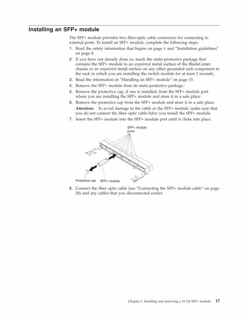
Installing an SFP+ moduleThe SFP+ module provides two fiber-optic cable connectors for connecting toexternal ports. To install an SFP+ module, complete the following steps:1. Read the safety information that begins on page v and “Installation guidelines”
on page 8.2. If you have not already done so, touch the static-protective package that
contains the SFP+ module to an unpainted metal surface of the BladeCenterchassis or an unpainted metal surface on any other grounded rack component inthe rack in which you are installing the switch module for at least 2 seconds.
3. Read the information in “Handling an SFP+ module” on page 15.4. Remove the SFP+ module from its static-protective package.5. Remove the protective cap, if one is installed, from the SFP+ module port
where you are installing the SFP+ module and store it in a safe place.6. Remove the protective cap from the SFP+ module and store it in a safe place.
Attention: To avoid damage to the cable or the SFP+ module, make sure thatyou do not connect the fiber optic cable before you install the SFP+ module.
7. Insert the SFP+ module into the SFP+ module port until it clicks into place.
8. Connect the fiber optic cable (see “Connecting the SFP+ module cable” on page20) and any cables that you disconnected earlier.
Chapter 3. Installing and removing a 10 Gb SFP+ module 17
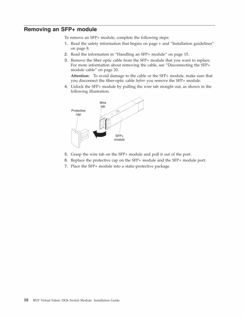
Removing an SFP+ moduleTo remove an SFP+ module, complete the following steps:1. Read the safety information that begins on page v and “Installation guidelines”
on page 8.2. Read the information in “Handling an SFP+ module” on page 15.3. Remove the fiber optic cable from the SFP+ module that you want to replace.
For more information about removing the cable, see “Disconnecting the SFP+module cable” on page 20.Attention: To avoid damage to the cable or the SFP+ module, make sure thatyou disconnect the fiber-optic cable before you remove the SFP+ module.
4. Unlock the SFP+ module by pulling the wire tab straight out, as shown in thefollowing illustration.
5. Grasp the wire tab on the SFP+ module and pull it out of the port.6. Replace the protective cap on the SFP+ module and the SFP+ module port.7. Place the SFP+ module into a static-protective package.
18 BNT Virtual Fabric 10Gb Switch Module: Installation Guide
Chapter 4. Cabling the switch module and the SFP+ module
This chapter describes how to cable the switch module and its optional devices.
Note: The illustrations in this document might differ slightly from your hardware.
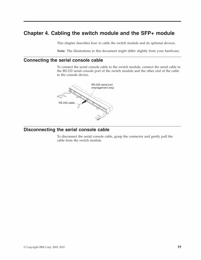
Connecting the serial console cableTo connect the serial console cable to the switch module, connect the serial cable tothe RS-232 serial console port of the switch module and the other end of the cableto the console device.
Disconnecting the serial console cableTo disconnect the serial console cable, grasp the connector and gently pull thecable from the switch module.
© Copyright IBM Corp. 2009, 2010 19
Connecting the SFP+ module cableAttention: To avoid damage to the fiber optic cables, follow these guidelines:v Do not route the cable along a folding cable-management arm.v When you attach the cable to a device on slide rails, leave enough slack in the
cable so that it does not bend to a radius of less than 38 mm (1.5 in.) when thedevice is extended or become pinched when the device is retracted.
v Route the cable away from places where it can be snagged by other devices inthe rack.
v Do not overtighten the cable straps or bend the cables to a radius of less than 38mm (1.5 in.).
v Do not put excess weight on the cable at the connection point. Make sure thatthe cable is well supported.
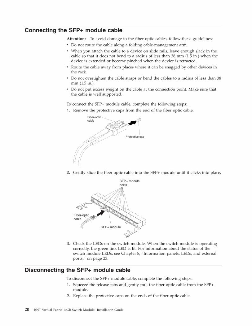
To connect the SFP+ module cable, complete the following steps:1. Remove the protective caps from the end of the fiber optic cable.
Protective cap
Fiber-opticcable
2. Gently slide the fiber optic cable into the SFP+ module until it clicks into place.
3. Check the LEDs on the switch module. When the switch module is operatingcorrectly, the green link LED is lit. For information about the status of theswitch module LEDs, see Chapter 5, “Information panels, LEDs, and externalports,” on page 23.
Disconnecting the SFP+ module cableTo disconnect the SFP+ module cable, complete the following steps:1. Squeeze the release tabs and gently pull the fiber optic cable from the SFP+
module.2. Replace the protective caps on the ends of the fiber optic cable.
20 BNT Virtual Fabric 10Gb Switch Module: Installation Guide
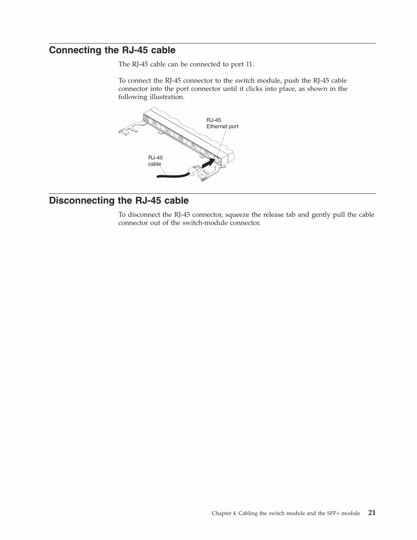
Connecting the RJ-45 cableThe RJ-45 cable can be connected to port 11.
To connect the RJ-45 connector to the switch module, push the RJ-45 cableconnector into the port connector until it clicks into place, as shown in thefollowing illustration.
Disconnecting the RJ-45 cableTo disconnect the RJ-45 connector, squeeze the release tab and gently pull the cableconnector out of the switch-module connector.
Chapter 4. Cabling the switch module and the SFP+ module 21

22 BNT Virtual Fabric 10Gb Switch Module: Installation Guide
Chapter 5. Information panels, LEDs, and external ports
This chapter describes the information panels and LEDs on the switch module andidentifies the external ports on the information panels.
Note: The illustrations in this document might differ slightly from your hardware.
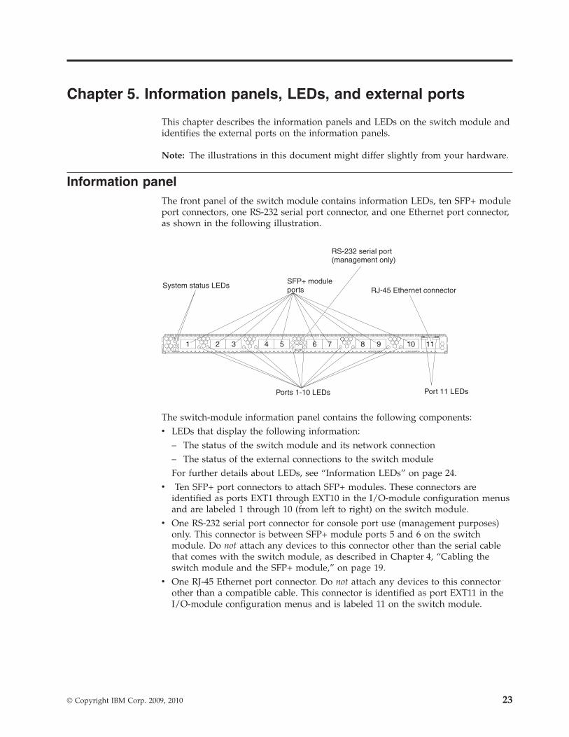
Information panelThe front panel of the switch module contains information LEDs, ten SFP+ moduleport connectors, one RS-232 serial port connector, and one Ethernet port connector,as shown in the following illustration.
The switch-module information panel contains the following components:v LEDs that display the following information:
– The status of the switch module and its network connection– The status of the external connections to the switch moduleFor further details about LEDs, see “Information LEDs” on page 24.
v Ten SFP+ port connectors to attach SFP+ modules. These connectors areidentified as ports EXT1 through EXT10 in the I/O-module configuration menusand are labeled 1 through 10 (from left to right) on the switch module.
v One RS-232 serial port connector for console port use (management purposes)only. This connector is between SFP+ module ports 5 and 6 on the switchmodule. Do not attach any devices to this connector other than the serial cablethat comes with the switch module, as described in Chapter 4, “Cabling theswitch module and the SFP+ module,” on page 19.
v One RJ-45 Ethernet port connector. Do not attach any devices to this connectorother than a compatible cable. This connector is identified as port EXT11 in theI/O-module configuration menus and is labeled 11 on the switch module.
© Copyright IBM Corp. 2009, 2010 23
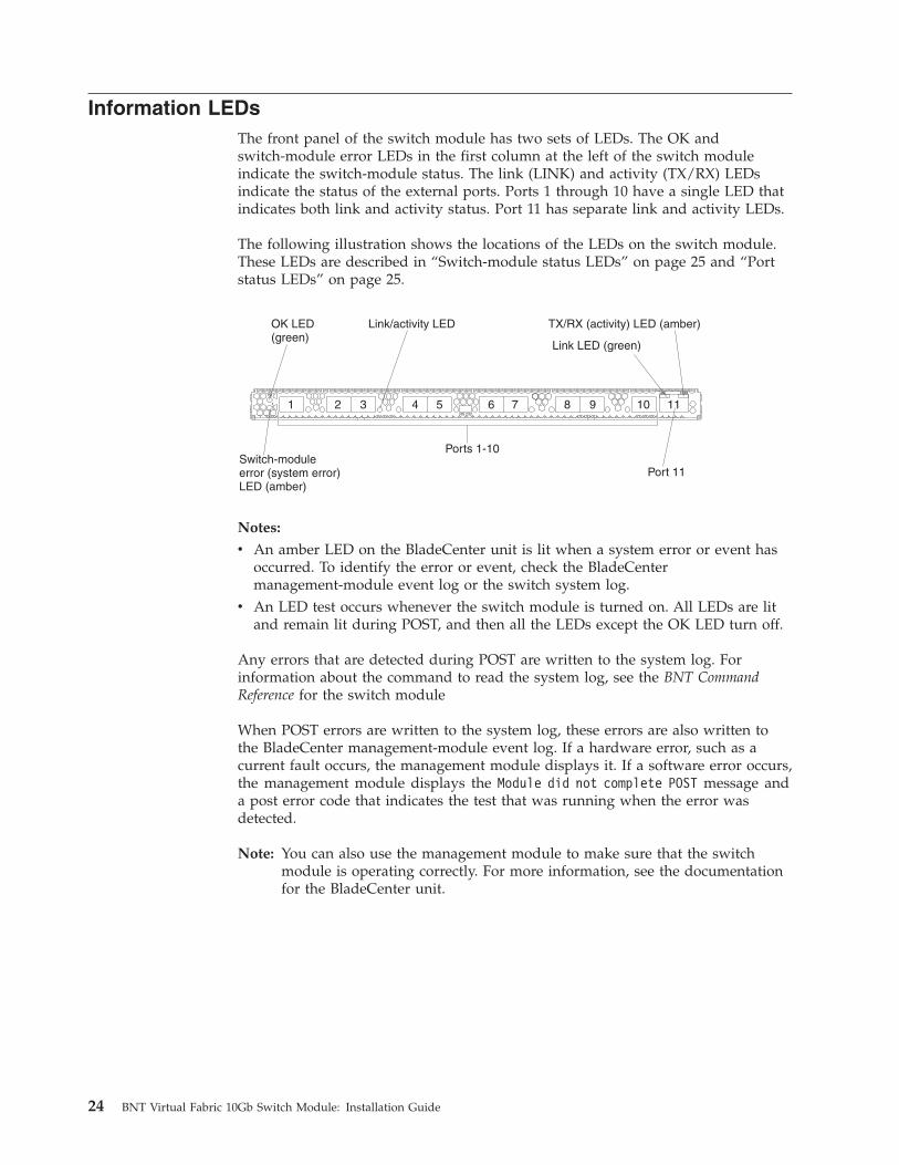
Information LEDsThe front panel of the switch module has two sets of LEDs. The OK andswitch-module error LEDs in the first column at the left of the switch moduleindicate the switch-module status. The link (LINK) and activity (TX/RX) LEDsindicate the status of the external ports. Ports 1 through 10 have a single LED thatindicates both link and activity status. Port 11 has separate link and activity LEDs.
The following illustration shows the locations of the LEDs on the switch module.These LEDs are described in “Switch-module status LEDs” on page 25 and “Portstatus LEDs” on page 25.
Notes:
v An amber LED on the BladeCenter unit is lit when a system error or event hasoccurred. To identify the error or event, check the BladeCentermanagement-module event log or the switch system log.
v An LED test occurs whenever the switch module is turned on. All LEDs are litand remain lit during POST, and then all the LEDs except the OK LED turn off.
Any errors that are detected during POST are written to the system log. Forinformation about the command to read the system log, see the BNT CommandReference for the switch module
When POST errors are written to the system log, these errors are also written tothe BladeCenter management-module event log. If a hardware error, such as acurrent fault occurs, the management module displays it. If a software error occurs,the management module displays the Module did not complete POST message anda post error code that indicates the test that was running when the error wasdetected.
Note: You can also use the management module to make sure that the switchmodule is operating correctly. For more information, see the documentationfor the BladeCenter unit.
24 BNT Virtual Fabric 10Gb Switch Module: Installation Guide
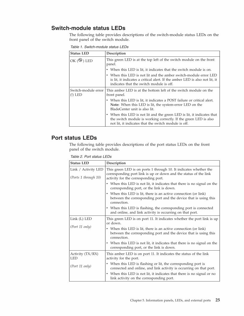
Switch-module status LEDsThe following table provides descriptions of the switch-module status LEDs on thefront panel of the switch module.
Table 1. Switch-module status LEDs
Status LED Description
OK ( ) LED This green LED is at the top left of the switch module on the frontpanel.
v When this LED is lit, it indicates that the switch module is on.
v When this LED is not lit and the amber switch-module error LEDis lit, it indicates a critical alert. If the amber LED is also not lit, itindicates that the switch module is off.
Switch-module error(!) LED
This amber LED is at the bottom left of the switch module on thefront panel.
v When this LED is lit, it indicates a POST failure or critical alert.Note: When this LED is lit, the system-error LED on theBladeCenter unit is also lit.
v When this LED is not lit and the green LED is lit, it indicates thatthe switch module is working correctly. If the green LED is alsonot lit, it indicates that the switch module is off.
Port status LEDsThe following table provides descriptions of the port status LEDs on the frontpanel of the switch module.
Table 2. Port status LEDs
Status LED Description
Link / Activity LED
(Ports 1 through 10)
This green LED is on ports 1 through 10. It indicates whether thecorresponding port link is up or down and the status of the linkactivity for the corresponding port.
v When this LED is not lit, it indicates that there is no signal on thecorresponding port, or the link is down.
v When this LED is lit, there is an active connection (or link)between the corresponding port and the device that is using thisconnection.
v When this LED is flashing, the corresponding port is connectedand online, and link activity is occurring on that port.
Link (L) LED
(Port 11 only)
This green LED is on port 11. It indicates whether the port link is upor down.
v When this LED is lit, there is an active connection (or link)between the corresponding port and the device that is using thisconnection.
v When this LED is not lit, it indicates that there is no signal on thecorresponding port, or the link is down.
Activity (TX/RX)LED
(Port 11 only)
This amber LED is on port 11. It indicates the status of the linkactivity for the port.
v When this LED is flashing or lit, the corresponding port isconnected and online, and link activity is occurring on that port.
v When this LED is not lit, it indicates that there is no signal or nolink activity on the corresponding port.
Chapter 5. Information panels, LEDs, and external ports 25

26 BNT Virtual Fabric 10Gb Switch Module: Installation Guide
Chapter 6. Configuring the switch module
The switch module has an internal Ethernet path to the management module,eleven external Ethernet ports, and a serial console port. The switch modulesupports two remote-access modes for management through Ethernet connections.You can select the mode that is best suited for your BladeCenter environment.v Default mode: The default mode uses the internal path to the management
module only. In this mode, the remote-access link to the management consolemust be attached to the Ethernet connector on the management module. TheInternet protocol (IP) addresses and SNMP parameters of the switch modulescan be automatically assigned by the IBM Director BladeCenter Deploymentwizard (when available), or you must assign them through the BladeCenterManagement and Configuration Program. This mode enables you to provide asecure LAN for management of the BladeCenter subsystems that is separatefrom the data network. See “Establishing a TCP/IP session through themanagement module” on page 28 for more information.
v Remote management mode: You can enable remote management of the switchmodule through the eleven external ports, instead of or in addition to accessthrough the management module. This mode can be enabled only through themanagement-module configuration interface. When this mode is enabled, the tenexternal SFP+ ports and the external RJ-45 Ethernet port support bothmanagement traffic and BladeCenter application data traffic.This mode enables the use of additional switch-module IP addresses on differentIP subnets than the management modules. This is useful when the switchmodules are to be managed and controlled as part of the overall networkinfrastructure, while secure management of other BladeCenter subsystems ismaintained through the management module. See “Enabling managementthrough external ports” on page 29 for additional instructions about configuringthe switch module for this mode of operation.
The RS-232 console port provides an alternative path to manage and configure theswitch for local access.
Important:
v Before you configure the switch module, make sure that the managementmodules in the BladeCenter unit are correctly configured. For more informationabout configuring the switch module, see the following documents:– Installation and User’s Guide for the BladeCenter unit– BladeCenter Advanced Management Module Installation Guide or BladeCenter T
Advanced Management Module Installation Guide
– IBM BladeCenter Advanced Management Module User’s Guide
v The default IP address of the switch module is 192.168.70.133, 192.168.70.134,192.168.70.135, or 192.168.70.136, depending on the switch-module bay where itis installed.
v If you change the IP address of the switch module and restart the BladeCenterunit, the switch module maintains this new IP address as its default value.
v The management module and the switch module can communicate with eachother only if they are on the same IP subnet.
v When you use the management-module Web interface to update theswitch-module configuration, the management-module firmware saves the new
© Copyright IBM Corp. 2009, 2010 27
configuration in its internal nonvolatile random-access memory (NVRAM). If theswitch module restarts, the management module applies the saved configurationto the switch module.If the switch module restarts and the management module cannot apply thesaved configuration, the switch module defaults to using the configuration thatit had previously saved. If the IP subnet address of the switch module does notmatch the IP subnet address of the management module, you can no longermanage the switch module from the management module.
v For switch communication with a remote management station, such as an IBMDirector management server, through the management-module external Ethernetport, the switch-module internal-network interface and the management-moduleexternal interface must be on the same IP subnet.
For specific details about configuring the switch module and preparing for systeminstallation, see the documentation listed in “Related documentation” on page 3.
Notes:
v Unless otherwise stated, references to the management module apply only to theBladeCenter Advanced Management Module, which is the only type ofmanagement module that supports the switch module.
v Throughout this document, the management-module Web-based user interface isalso known as the BladeCenter management-module Web interface.
v Throughout this document, the user name is also known as the login name oruser ID for logging on to interfaces or programs.
v The screens that are described or referenced in this document might differslightly from the screens that are displayed by your system. Screen contentvaries according to the type of BladeCenter unit and the firmware versions andoptions that are installed.
Establishing a TCP/IP session through the management moduleTo establish a TCP/IP session for the switch module through the managementmodule, complete the following steps:1. Log on to the management module as described in the User’s Guide or
Command Line Interface Reference Guide for your advanced management module.If necessary, obtain the IP address of the management module from yoursystem administrator. The management-module window opens.
Note: The User ID and Password fields are case-sensitive. Type yourinformation in uppercase letters only. To maintain system security,change your password after you log on for the first time. The defaultUser ID is USERID, and the default password is PASSW0RD (where the sixthcharacter is the number zero, not the letter O).
2. From the I/O Module Tasks menu, click Configuration.3. In the I/O Module Configuration area, click the bay number that corresponds
to the location of the switch module that you installed.4. In the IP address field in the New Static IP Configuration area, type the new
TCP/IP address of the switch module; then, click Save.
Note: The management module does not check for invalid IP addresses.5. Click Advanced Configuration. You can now start a Web session or a Telnet
session.
28 BNT Virtual Fabric 10Gb Switch Module: Installation Guide
The Web interface and the Telnet program provide different ways to access thesame internal-switching software and configure it.v If your system application requires that you use the Web interface program, see
“Configuring the switch module through the switch-module browser-basedinterface” on page 32 for additional information.
v If your system application requires that you use the Telnet program, see“Configuring the switch module through the Telnet interface” on page 30 foradditional information.
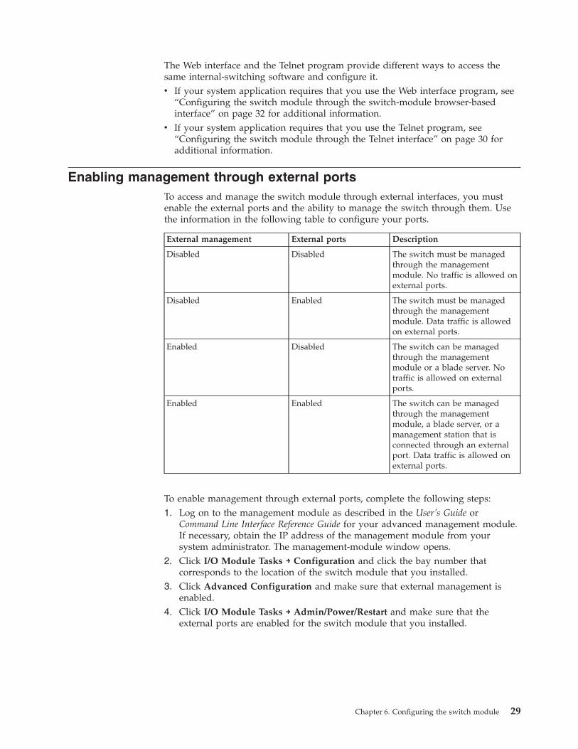
Enabling management through external portsTo access and manage the switch module through external interfaces, you mustenable the external ports and the ability to manage the switch through them. Usethe information in the following table to configure your ports.
External management External ports Description
Disabled Disabled The switch must be managedthrough the managementmodule. No traffic is allowed onexternal ports.
Disabled Enabled The switch must be managedthrough the managementmodule. Data traffic is allowedon external ports.
Enabled Disabled The switch can be managedthrough the managementmodule or a blade server. Notraffic is allowed on externalports.
Enabled Enabled The switch can be managedthrough the managementmodule, a blade server, or amanagement station that isconnected through an externalport. Data traffic is allowed onexternal ports.
To enable management through external ports, complete the following steps:1. Log on to the management module as described in the User’s Guide or
Command Line Interface Reference Guide for your advanced management module.If necessary, obtain the IP address of the management module from yoursystem administrator. The management-module window opens.
2. Click I/O Module Tasks → Configuration and click the bay number thatcorresponds to the location of the switch module that you installed.
3. Click Advanced Configuration and make sure that external management isenabled.
4. Click I/O Module Tasks → Admin/Power/Restart and make sure that theexternal ports are enabled for the switch module that you installed.
Chapter 6. Configuring the switch module 29
Configuring the switch module through the Telnet interfaceThe switch module supports a command-line interface (CLI) that you can use toconfigure and control the switch module over the network through the Telnetprogram. You can use the CLI to perform many basic network-managementfunctions. In addition, you can configure the switch module for managementthrough an SNMP-based network-management system. The following sectionsdescribe how to use the Telnet interface to access the switch module, change itssettings, and monitor its operation.
Connecting to the switch moduleIf you know the IP address for the switch module and you have an existingnetwork connection, you can use the Telnet program from an external managementstation or the management module to access and control the switch module. Themanagement station and the switch module must be on the same IP subnet. If youhave to obtain the IP address for the switch module or establish a networkconnection, contact your system or network administrator. Be sure to use thecorrect IP address in the required command, as specified in “Accessing the mainmenu.”
Accessing the main menuTo connect to the switch module through the Telnet interface, complete thefollowing steps:1. From a DOS command-line prompt, type telnet x and press Enter.
where x is the IP address for the switch module.2. If you do not have an assigned initial password, in the Password field, type the
default password (admin) and press Enter.
Important: The apply command changes the currently active configuration. If youwant your change to persist beyond the next reboot of the switch, you must enterthe save command. This command stores the current switch configuration and allchanges in nonvolatile memory.
For more information about configuring through the CLI, see the BNT 10-Port 10GbEthernet Switch Module for IBM BladeCenter Command Reference.
30 BNT Virtual Fabric 10Gb Switch Module: Installation Guide
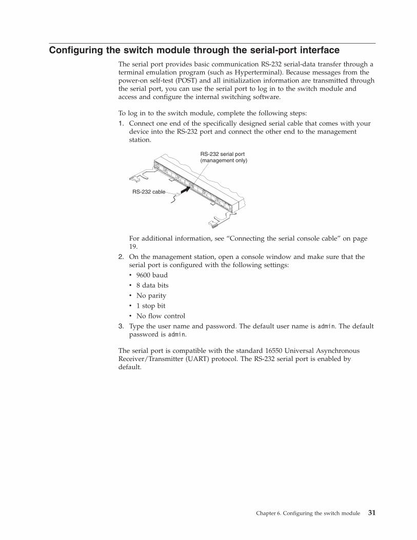
Configuring the switch module through the serial-port interfaceThe serial port provides basic communication RS-232 serial-data transfer through aterminal emulation program (such as Hyperterminal). Because messages from thepower-on self-test (POST) and all initialization information are transmitted throughthe serial port, you can use the serial port to log in to the switch module andaccess and configure the internal switching software.
To log in to the switch module, complete the following steps:1. Connect one end of the specifically designed serial cable that comes with your
device into the RS-232 port and connect the other end to the managementstation.
For additional information, see “Connecting the serial console cable” on page19.
2. On the management station, open a console window and make sure that theserial port is configured with the following settings:v 9600 baudv 8 data bitsv No parityv 1 stop bitv No flow control
3. Type the user name and password. The default user name is admin. The defaultpassword is admin.
The serial port is compatible with the standard 16550 Universal AsynchronousReceiver/Transmitter (UART) protocol. The RS-232 serial port is enabled bydefault.
Chapter 6. Configuring the switch module 31
Configuring the switch module through the switch-modulebrowser-based interface
This section describes how to use the switch-module browser-based interface (BBI)to access and configure the internal switching software. For more informationabout the BBI, see the BNT 10-Port 10Gb Ethernet Switch Module for IBM BladeCenterBrowser Based Interface Quick Guide.
This section also describes some of the Web interface switch-module managementfeatures.
The switch module offers an embedded HTML, browser-based interface that youcan use to manage the switch through Netscape Navigator and Communicator,Mozilla Firefox, or Microsoft Internet Explorer. This interface is enabled by default.The browser-based interface acts as an access tool and can communicate directlywith the switch through HTTP. Your computer might have to access and install aJava plug-in (JRE 1.4.0) to run without errors. Later versions of the JRE might workbut are not officially supported.
Note: This interface does not accept Chinese-language input (or other double-bytecharacter-set languages).
Before you can access and start the browser-based interface, make sure that youhave completed the following procedures:v Install the switch module in the BladeCenter unit.v Make sure that the switch-module software is installed on the switch module.v Configure at least one IP interface on the switch module.v Enable frames and the JavaScript program in your Web browser.
The following hardware and software are required for the Web interface:v A frame-capable Web-browser program, such as Internet Explorer (version 6.0 or
later), Mozilla Firefox (version 1.0.4 or later), or Netscape Navigator (version 4.7or later)
v A computer or workstation with network access to the switch module
To start the browser-based interface, complete the following steps:1. Start a Web browser. The Web-browser window opens.2. In the URL field, enter the IP address of the switch module, in the following
format:http://xxx.xxx.xxx.xxx. The login window opens.
3. Enter your user ID and password and click OK. The default user ID is admin.The default password is admin.
Note: The passwords that are used to access the switch module are case-sensitive.To increase system security, change the password after you log on for thefirst time.
32 BNT Virtual Fabric 10Gb Switch Module: Installation Guide
Initial configurationThe operating software on the switch module contains default configuration filesthat are installed during the software installation. These initial configurationsettings are not in a separate configuration file but are components of the software.When you restore the management module to factory defaults, the originalconfiguration is restored. For more information about configuring and managingthe switch module through the management module, see the BNT CommandReference for the switch module.
Logging in to the switch moduleThe switch module supports user-based security that enables you to preventunauthorized users from accessing the switch or changing its settings.
To log in to the switch module, complete the following steps:1. At the prompt, type your user ID and press Enter. The default user ID is admin.2. Type your password (default is admin) and press Enter. The default password is
admin. The main-menu window opens.
After you log on to the switch module, you must set the date and time. See theCommand Reference for thhe switch module to perform this task and others asneeded.
Chapter 6. Configuring the switch module 33

34 BNT Virtual Fabric 10Gb Switch Module: Installation Guide
Chapter 7. Updating the software
This chapter describes how to determine the level of the software that is installedon the switch module, how to obtain the latest level of switch software, how toupgrade the software, and how to reset the switch module to activate the softwareupgrade.
Determining the level of switch-module softwareAfter you install the switch module in the BladeCenter unit, make sure that thelatest software is installed on the switch module. To determine the level of thesoftware that is installed, complete the following steps:1. Log on to the management module as described in the IBM BladeCenter
Advanced Management Module User’s Guide. If necessary, obtain the IP address ofthe management module from your system administrator. The login windowopens.
2. From the Monitors menu, click Firmware VPD. The Firmware VPD windowopens.
3. In the I/O Module Firmware VPD area, locate the number of theI/O-module-bay that contains the switch module that you installed; then, notethe corresponding level of the software for the switch module.
Obtaining the latest level of switch softwareThe switch module might have features that are not described in thedocumentation that comes with the switch, and the documentation might beupdated occasionally to include information about those features or technicalupdates.
If firmware and documentation updates are available, complete the followingsteps:
Note: Changes are made periodically to the IBM Web site. The procedure forlocating firmware and documentation might change from what is describedin this document.
1. Go to http://www.ibm.com/systems/support/.2. Under Product support, click BladeCenter.3. In the column on the left, click BladeCenter support search.4. In the Search for field, type bnt 10 gb, and click Search.5. In the Task field, select Download, and then click Search.
The switch module can contain two operating-system images. You can revert to theprevious image if the current download process fails.
© Copyright IBM Corp. 2009, 2010 35
Upgrading the switch-module softwareYou can upgrade the switch-module software by using a TFTP server application.Typically, this software runs as an application under your operating system. Makesure that this software is installed on your server; then, download the softwareimages from http://www.ibm.com/systems/support/ into a directory on yourTFTP server. Enable the TFTP server and set its default directory to the one wherethe image is.
To transfer the software image files from the TFTP server to the switch, you canestablish a Telnet session through the management module. Ping the TFTP serverto make sure that you have a connection. The Telnet session performs optimally ifall three network entities (TFTP server, management module, and switch IPaddresses) are on the same subnet. Otherwise, you must use a router and configurea gateway address on the switch. Use the management-module interface toconfigure the IP addresses of the management module external interface (eth0) andthe switch module so that they are both on the same subnet as the TFTP server.
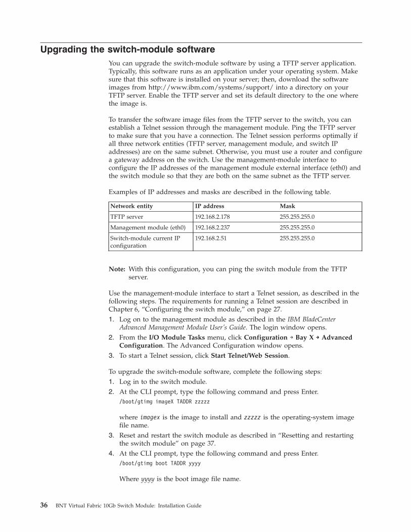
Examples of IP addresses and masks are described in the following table.
Network entity IP address Mask
TFTP server 192.168.2.178 255.255.255.0
Management module (eth0) 192.168.2.237 255.255.255.0
Switch-module current IPconfiguration
192.168.2.51 255.255.255.0
Note: With this configuration, you can ping the switch module from the TFTPserver.
Use the management-module interface to start a Telnet session, as described in thefollowing steps. The requirements for running a Telnet session are described inChapter 6, “Configuring the switch module,” on page 27.1. Log on to the management module as described in the IBM BladeCenter
Advanced Management Module User’s Guide. The login window opens.2. From the I/O Module Tasks menu, click Configuration → Bay X → Advanced
Configuration. The Advanced Configuration window opens.3. To start a Telnet session, click Start Telnet/Web Session.
To upgrade the switch-module software, complete the following steps:1. Log in to the switch module.2. At the CLI prompt, type the following command and press Enter.
/boot/gtimg imageX TADDR zzzzz
where imagex is the image to install and zzzzz is the operating-system imagefile name.
3. Reset and restart the switch module as described in “Resetting and restartingthe switch module” on page 37.
4. At the CLI prompt, type the following command and press Enter./boot/gtimg boot TADDR yyyy
Where yyyy is the boot image file name.
36 BNT Virtual Fabric 10Gb Switch Module: Installation Guide
5. Reset and restart the switch module as described in “Resetting and restartingthe switch module.”
Resetting and restarting the switch moduleTo activate the new image or images, you must reset the switch module. To resetthe switch module, complete the following steps:1. From the I/O Module Tasks menu, click Admin/Power/Restart. The
management module window opens.2. Select the I/O-module bay on which the software update was just installed.3. Click Power Off Module(s).4. Select the I/O-module bay on which the software update was just installed.5. Click Power On Module(s). Wait 60 seconds for POST to be completed.6. Click Monitors, and select Firmware VPD. The Firmware VPD window opens.7. In the Firmware VPD window, locate the I/O Module Firmware VPD area.
Page down to the number of the I/O-module bay that contains the switchmodule that you just installed; then, note the corresponding level of thesoftware for the switch module. Confirm that the software build ID andrevision reflect the correct software release.
Chapter 7. Updating the software 37

38 BNT Virtual Fabric 10Gb Switch Module: Installation Guide
Chapter 8. Parts listing
Replaceable components are of three types:v Tier 1 customer replaceable unit (CRU): Replacement of Tier 1 CRUs is your
responsibility. If IBM installs a Tier 1 CRU at your request, you will be chargedfor the installation.
v Tier 2 customer replaceable unit (CRU): You may install a Tier 2 CRU yourselfor request IBM to install it, at no additional charge, under the type of warrantyservice that is designated for your server.
v Field replaceable unit (FRU): FRUs must be installed only by trained servicetechnicians.
For information about the terms of the warranty, see the Warranty Informationdocument.
The replaceable components in the following table are Tier 1 CRUs. If otherBladeCenter components require replacement, see the following documentationthat comes with these devices:v BladeCenter Problem Determination and Service Guide or Hardware Maintenance
Manual and Troubleshooting Guide
v Installation and User’s Guide or Installation Guide
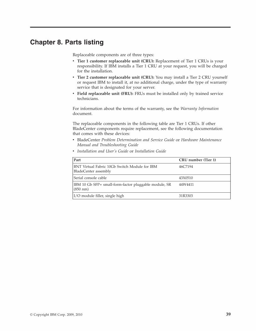
Part CRU number (Tier 1)
BNT Virtual Fabric 10Gb Switch Module for IBMBladeCenter assembly
46C7194
Serial console cable 43X0510
IBM 10 Gb SFP+ small-form-factor pluggable module, SR(850 nm)
44W4411
I/O module filler, single high 31R3303
© Copyright IBM Corp. 2009, 2010 39

40 BNT Virtual Fabric 10Gb Switch Module: Installation Guide
Chapter 9. Solving problems
This section provides basic troubleshooting information to help you solve someproblems that might occur while you are setting up the switch module. TheApplication Guide for the switch module provides more details abouttroubleshooting the switch module.
If you cannot locate and correct a problem by using the information in this section,see Appendix A, “Getting help and technical assistance,” on page 43.
Running POSTTo ensure that it is fully operational, the switch module processes a series of testsduring power-up or a restart (power-on self-test, or POST). These tests takeapproximately 1 minute to complete. The management module reads the testresults and displays them for you. During normal operation, these tests arecompleted without error, and the green OK LED is lit. However, if the switchmodule fails POST, the amber switch-module error LED and the system-error LEDon the BladeCenter unit are lit. An event is stored in the event log in the systemstatus panel of the management module. The specific failure is displayed on thesystem status I/O module panel of the management module.
Note: For the locations and descriptions of the switch module LEDs, see Chapter 5,“Information panels, LEDs, and external ports,” on page 23.
POST errorsThere are two types of errors: noncritical and critical. A noncritical error applies toone port, and the switch module is operational. You can continue to operate theswitch module; however, you must replace it as soon as possible. When criticalerrors occur, the switch module does not operate. To view POST results, completethe following steps:1. Log on to the management module as described in the IBM BladeCenter
Advanced Management Module Command-Line Interface Reference Guide. Ifnecessary, obtain the IP address of the management module from your systemadministrator. The login window opens.
2. Turn off the power to the switch module; then, turn it on again.3. After POST is completed, the management module displays the results. Refresh
the window to view the POST results. If a critical error occurs, replace theswitch module. If a noncritical error occurs, see the switch-module error log foradditional details.
© Copyright IBM Corp. 2009, 2010 41
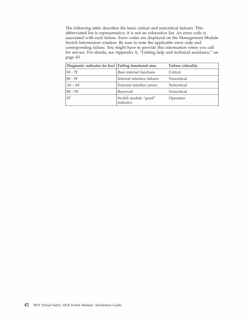
The following table describes the basic critical and noncritical failures. Thisabbreviated list is representative; it is not an exhaustive list. An error code isassociated with each failure. Error codes are displayed on the Management ModuleSwitch Information window. Be sure to note the applicable error code andcorresponding failure. You might have to provide this information when you callfor service. For details, see Appendix A, “Getting help and technical assistance,” onpage 43.
Diagnostic indicator (in hex) Failing functional area Failure criticality
00 - 7F Base internal functions Critical
80 - 9F Internal interface failures Noncritical
A0 - AF External interface errors Noncritical
B0 - FE Reserved Noncritical
FF Switch module “good”indicator
Operation
42 BNT Virtual Fabric 10Gb Switch Module: Installation Guide
Appendix A. Getting help and technical assistance
If you need help, service, or technical assistance or just want more informationabout IBM products, you will find a wide variety of sources available from IBM toassist you. This section contains information about where to go for additionalinformation about IBM and IBM products, what to do if you experience a problemwith your system, and whom to call for service, if it is necessary.
Before you callBefore you call, make sure that you have taken these steps to try to solve theproblem yourself:v Check all cables to make sure that they are connected.v Check the power switches to make sure that the system and any optional
devices are turned on.v Use the troubleshooting information in your system documentation, and use the
diagnostic tools that come with your system. Information about diagnostic toolsis in the Problem Determination and Service Guide on the IBM Documentation CDthat comes with your system.
v Go to the IBM support Web site at http://www.ibm.com/systems/support/ tocheck for technical information, hints, tips, and new device drivers or to submita request for information.
You can solve many problems without outside assistance by following thetroubleshooting procedures that IBM provides in the online help or in thedocumentation that is provided with your IBM product. The documentation thatcomes with IBM systems also describes the diagnostic tests that you can perform.Most systems, operating systems, and programs come with documentation thatcontains troubleshooting procedures and explanations of error messages and errorcodes. If you suspect a software problem, see the documentation for the operatingsystem or program.
Using the documentationInformation about your IBM system and preinstalled software, if any, or optionaldevice is available in the documentation that comes with the product. Thatdocumentation can include printed documents, online documents, readme files,and help files. See the troubleshooting information in your system documentationfor instructions for using the diagnostic programs. The troubleshooting informationor the diagnostic programs might tell you that you need additional or updateddevice drivers or other software. IBM maintains pages on the World Wide Webwhere you can get the latest technical information and download device driversand updates. To access these pages, go to http://www.ibm.com/systems/support/and follow the instructions. Also, some documents are available through the IBMPublications Center at http://www.ibm.com/shop/publications/order/.
© Copyright IBM Corp. 2009, 2010 43
Getting help and information from the World Wide WebOn the World Wide Web, the IBM Web site has up-to-date information about IBMsystems, optional devices, services, and support. The address for IBM System x®
and xSeries® information is http://www.ibm.com/systems/x/. The address forIBM BladeCenter information is http://www.ibm.com/systems/bladecenter/. Theaddress for IBM IntelliStation® information is http://www.ibm.com/intellistation/.
You can find service information for IBM systems and optional devices athttp://www.ibm.com/systems/support/.
Software service and supportThrough IBM Support Line, you can get telephone assistance, for a fee, with usage,configuration, and software problems with System x and xSeries servers,BladeCenter products, IntelliStation workstations, and appliances. For informationabout which products are supported by Support Line in your country or region,see http://www.ibm.com/services/sl/products/.
For more information about Support Line and other IBM services, seehttp://www.ibm.com/services/, or see http://www.ibm.com/planetwide/ forsupport telephone numbers. In the U.S. and Canada, call 1-800-IBM-SERV(1-800-426-7378).
Hardware service and supportYou can receive hardware service through your IBM reseller or IBM Services. Tolocate a reseller authorized by IBM to provide warranty service, go tohttp://www.ibm.com/partnerworld/ and click Find a Business Partner on theright side of the page. For IBM support telephone numbers, seehttp://www.ibm.com/planetwide/. In the U.S. and Canada, call 1-800-IBM-SERV(1-800-426-7378).
In the U.S. and Canada, hardware service and support is available 24 hours a day,7 days a week. In the U.K., these services are available Monday through Friday,from 9 a.m. to 6 p.m.
IBM Taiwan product service
IBM Taiwan product service contact information:IBM Taiwan Corporation3F, No 7, Song Ren Rd.Taipei, TaiwanTelephone: 0800-016-888
44 BNT Virtual Fabric 10Gb Switch Module: Installation Guide
Appendix B. Notices
This information was developed for products and services offered in the U.S.A.
IBM may not offer the products, services, or features discussed in this document inother countries. Consult your local IBM representative for information on theproducts and services currently available in your area. Any reference to an IBMproduct, program, or service is not intended to state or imply that only that IBMproduct, program, or service may be used. Any functionally equivalent product,program, or service that does not infringe any IBM intellectual property right maybe used instead. However, it is the user’s responsibility to evaluate and verify theoperation of any non-IBM product, program, or service.
IBM may have patents or pending patent applications covering subject matterdescribed in this document. The furnishing of this document does not give youany license to these patents. You can send license inquiries, in writing, to:
IBM Director of LicensingIBM CorporationNorth Castle DriveArmonk, NY 10504-1785U.S.A.
INTERNATIONAL BUSINESS MACHINES CORPORATION PROVIDES THISPUBLICATION “AS IS” WITHOUT WARRANTY OF ANY KIND, EITHEREXPRESS OR IMPLIED, INCLUDING, BUT NOT LIMITED TO, THE IMPLIEDWARRANTIES OF NON-INFRINGEMENT, MERCHANTABILITY OR FITNESSFOR A PARTICULAR PURPOSE. Some states do not allow disclaimer of express orimplied warranties in certain transactions, therefore, this statement may not applyto you.
This information could include technical inaccuracies or typographical errors.Changes are periodically made to the information herein; these changes will beincorporated in new editions of the publication. IBM may make improvementsand/or changes in the product(s) and/or the program(s) described in thispublication at any time without notice.
Any references in this information to non-IBM Web sites are provided forconvenience only and do not in any manner serve as an endorsement of those Websites. The materials at those Web sites are not part of the materials for this IBMproduct, and use of those Web sites is at your own risk.
IBM may use or distribute any of the information you supply in any way itbelieves appropriate without incurring any obligation to you.
TrademarksIBM, the IBM logo, and ibm.com are trademarks or registered trademarks ofInternational Business Machines Corporation in the United States, other countries,or both. If these and other IBM trademarked terms are marked on their firstoccurrence in this information with a trademark symbol (® or ™), these symbolsindicate U.S. registered or common law trademarks owned by IBM at the time thisinformation was published. Such trademarks may also be registered or common
© Copyright IBM Corp. 2009, 2010 45
law trademarks in other countries. A current list of IBM trademarks is available onthe Web at “Copyright and trademark information” at http://www.ibm.com/legal/copytrade.shtml.
Adobe and PostScript are either registered trademarks or trademarks of AdobeSystems Incorporated in the United States and/or other countries.
Cell Broadband Engine is a trademark of Sony Computer Entertainment, Inc., inthe United States, other countries, or both and is used under license therefrom.
Intel, Intel Xeon, Itanium, and Pentium are trademarks or registered trademarks ofIntel Corporation or its subsidiaries in the United States and other countries.
Java and all Java-based trademarks are trademarks of Sun Microsystems, Inc., inthe United States, other countries, or both.
Linux is a registered trademark of Linus Torvalds in the United States, othercountries, or both.
Microsoft, Windows, and Windows NT are trademarks of Microsoft Corporation inthe United States, other countries, or both.
UNIX is a registered trademark of The Open Group in the United States and othercountries.
Other company, product, or service names may be trademarks or service marks ofothers.
Important notesProcessor speed indicates the internal clock speed of the microprocessor; otherfactors also affect application performance.
CD or DVD drive speed is the variable read rate. Actual speeds vary and are oftenless than the possible maximum.
When referring to processor storage, real and virtual storage, or channel volume,KB stands for 1024 bytes, MB stands for 1 048 576 bytes, and GB stands for1 073 741 824 bytes.
When referring to hard disk drive capacity or communications volume, MB standsfor 1 000 000 bytes, and GB stands for 1 000 000 000 bytes. Total user-accessiblecapacity can vary depending on operating environments.
Maximum internal hard disk drive capacities assume the replacement of anystandard hard disk drives and population of all hard disk drive bays with thelargest currently supported drives that are available from IBM.
Maximum memory might require replacement of the standard memory with anoptional memory module.
IBM makes no representation or warranties regarding non-IBM products andservices that are ServerProven®, including but not limited to the implied warrantiesof merchantability and fitness for a particular purpose. These products are offeredand warranted solely by third parties.
46 BNT Virtual Fabric 10Gb Switch Module: Installation Guide

IBM makes no representations or warranties with respect to non-IBM products.Support (if any) for the non-IBM products is provided by the third party, not IBM.
Some software might differ from its retail version (if available) and might notinclude user manuals or all program functionality.
Electronic emission notices
Federal Communications Commission (FCC) statementNote: This equipment has been tested and found to comply with the limits for aClass A digital device, pursuant to Part 15 of the FCC Rules. These limits aredesigned to provide reasonable protection against harmful interference when theequipment is operated in a commercial environment. This equipment generates,uses, and can radiate radio frequency energy and, if not installed and used inaccordance with the instruction manual, may cause harmful interference to radiocommunications. Operation of this equipment in a residential area is likely to causeharmful interference, in which case the user will be required to correct theinterference at his own expense.
Properly shielded and grounded cables and connectors must be used in order tomeet FCC emission limits. IBM is not responsible for any radio or televisioninterference caused by using other than recommended cables and connectors or byunauthorized changes or modifications to this equipment. Unauthorized changesor modifications could void the user's authority to operate the equipment.
This device complies with Part 15 of the FCC Rules. Operation is subject to thefollowing two conditions: (1) this device may not cause harmful interference, and(2) this device must accept any interference received, including interference thatmay cause undesired operation.
Industry Canada Class A emission compliance statementThis Class A digital apparatus complies with Canadian ICES-003.
Avis de conformité à la réglementation d'Industrie CanadaCet appareil numérique de la classe A est conforme à la norme NMB-003 duCanada.
Australia and New Zealand Class A statementAttention: This is a Class A product. In a domestic environment this product maycause radio interference in which case the user may be required to take adequatemeasures.
United Kingdom telecommunications safety requirementNotice to Customers
This apparatus is approved under approval number NS/G/1234/J/100003 forindirect connection to public telecommunication systems in the United Kingdom.
European Union EMC Directive conformance statementThis product is in conformity with the protection requirements of EU CouncilDirective 2004/108/EC on the approximation of the laws of the Member Statesrelating to electromagnetic compatibility. IBM cannot accept responsibility for any
Appendix B. Notices 47

failure to satisfy the protection requirements resulting from a nonrecommendedmodification of the product, including the fitting of non-IBM option cards.
This product has been tested and found to comply with the limits for Class AInformation Technology Equipment according to CISPR 22/European Standard EN55022. The limits for Class A equipment were derived for commercial andindustrial environments to provide reasonable protection against interference withlicensed communication equipment.
Attention: This is a Class A product. In a domestic environment this product maycause radio interference in which case the user may be required to take adequatemeasures.
European Community contact:IBM Technical RegulationsPascalstr. 100, Stuttgart, Germany 70569Telephone: 0049 (0)711 785 1176Fax: 0049 (0)711 785 1283E-mail: [email protected]
Taiwanese Class A warning statement
Germany Electromagnetic Compatibility DirectiveDeutschsprachiger EU Hinweis:
Hinweis für Geräte der Klasse A EU-Richtlinie zur ElektromagnetischenVerträglichkeit
Dieses Produkt entspricht den Schutzanforderungen der EU-Richtlinie2004/108/EG zur Angleichung der Rechtsvorschriften über die elektromagnetischeVerträglichkeit in den EU-Mitgliedsstaaten und hält die Grenzwerte der EN 55022Klasse A ein.
Um dieses sicherzustellen, sind die Geräte wie in den Handbüchern beschrieben zuinstallieren und zu betreiben. Des Weiteren dürfen auch nur von der IBMempfohlene Kabel angeschlossen werden. IBM übernimmt keine Verantwortung fürdie Einhaltung der Schutzanforderungen, wenn das Produkt ohne Zustimmung derIBM verändert bzw. wenn Erweiterungskomponenten von Fremdherstellern ohneEmpfehlung der IBM gesteckt/eingebaut werden.
EN 55022 Klasse A Geräte müssen mit folgendem Warnhinweis versehen werden:“Warnung: Dieses ist eine Einrichtung der Klasse A. Diese Einrichtung kann im
48 BNT Virtual Fabric 10Gb Switch Module: Installation Guide

Wohnbereich Funk-Störungen verursachen; in diesem Fall kann vom Betreiberverlangt werden, angemessene Maßnahmen zu ergreifen und dafüraufzukommen.”
Deutschland: Einhaltung des Gesetzes über dieelektromagnetische Verträglichkeit von GerätenDieses Produkt entspricht dem “Gesetz über die elektromagnetische Verträglichkeitvon Geräten (EMVG)”. Dies ist die Umsetzung der EU-Richtlinie 2004/108/EG inder Bundesrepublik Deutschland.
Zulassungsbescheinigung laut dem Deutschen Gesetz über dieelektromagnetische Verträglichkeit von Geräten (EMVG) (bzw. derEMC EG Richtlinie 2004/108/EG) für Geräte der Klasse ADieses Gerät ist berechtigt, in Übereinstimmung mit dem Deutschen EMVG dasEG-Konformitätszeichen - CE - zu führen. Verantwortlich für dieKonformitätserklärung des EMVG ist die IBM Deutschland GmbH, 70548 Stuttgart.
Generelle Informationen:
Das Gerät erfüllt die Schutzanforderungen nach EN 55024 und EN 55022 KlasseA.
People's Republic of China Class A warning statement
Japanese Voluntary Control Council for Interference (VCCI)statement
Korean Class A warning statement
Appendix B. Notices 49

50 BNT Virtual Fabric 10Gb Switch Module: Installation Guide

Index
Aaccessing
main menu 30switch module
through the Telnet interface 30through the Web interface 32
Web interface 32activity (TX/RX) LED, Ethernet switch
module 24activity (TX/RX) LED, switch module or
SFP+ module port 25activity status, port
Ethernet switch module 24switch module or SFP+ module
port 25adapter, host channel 1assistance, getting 43attention notices 4
Bbay locations, BladeCenter unit 7blade server
interconnections with expansion cardand high-speed switch-modules 1,7
network requirements 1BladeCenter documentation Web site 3browser-based interface (BBI)
configuring the switch module 32connecting to the switch module 32starting a session 32
Ccables
requirements for Ethernetnetwork 11, 12
requirements for switch modules 9serial console
installing 19removing 19
SFP+ moduleinstalling 20removing 20
cablingparts listing 39serial console 19SFP+ module 20switch module 19
case-sensitive data fieldsaccessing the switch module 32logging on to the management
module 28caution statements 4Class A electronic emission notice 47Common Language Equipment
Identification (CLEI) label 5communication requirements 1, 7, 11
compatibleBladeCenter options Web site 8host channel adapter (HCA) 1
componentsinformation panel 23switch module 5
configurationcable requirements 9menu 23options 3settings 28Telnet interface requirements 30
configuringswitch module
for remote access 27initial configuration 33through the browser-based
interface 32through the serial-port
interface 31through the Telnet interface 30
connectingRJ-45 cable 21serial console cable 19SFP+ module cable 20
connecting to the switch modulethrough the browser-based
interface 32through the serial-port interface 31through the Telnet interface 30, 33
critical errors 41
Ddanger statements 4default IP address 27default remote-management mode 27determining the current level of switch
software 35disconnecting
RJ-45 cable 21serial console cable 19SFP+ module cable 20
documentationcable requirements 9related 3
Eelectronic emission Class A notice 47enabling management over external
ports 11enabling management through external
ports 29enabling the external ports 11, 29error
critical 41noncritical 41
error logmanagement module 24
error log (continued)power-on self-test (POST) 24
establishing a sessionthrough the management module 28through the Telnet interface 30through the Web interface 32
Ethernetexpansion card 1external management-module
ports 30LEDs 24, 25network requirements 11, 12ports 23, 25
Ethernet switch moduleactivity (TX/RX) LED 23, 24, 25components 5error (!) LED 25features, specifications, and
standards 3information panel 23installation guidelines 8installing 7, 10link LED 23, 24, 25OK LED 23, 24, 25ports 23, 25removing or replacing 12switch-module error (!) LED 23, 24
event log, management module 24expansion card
interconnections with blade serverand high-speed switch-modules 1,7
network requirements 1, 7external ports
enabling 11, 29enabling management 11, 29Ethernet
accessing the switch module 30cable requirements 11, 12
operating speeds on switchmodule 8
remote management 27status LEDs
on Ethernet switch module 23, 24on switch module or SFP+ module
port 25
FFCC Class A notice 47features 3fiber optic cables
installing 20removing 20
filler moduleinstallation requirements 10parts listing 39
front view 23, 24
© Copyright IBM Corp. 2009, 2010 51

Ggetting help 43guidelines
handling an SFP+ module 15handling fiber optic cables 20handling static-sensitive devices 9installation 8system reliability 8
Hhandling
an SFP+ module 15fiber optic cables 20static-sensitive devices 9
hardware features 3hardware requirements 1, 7hardware service and support 44help, getting 43high-speed device interconnections 1, 7high-speed switch-module (HSSM)
documentation 3network requirements 7
host channel adapter (HCA)interconnections with blade server
and high-speed switch-modules 1,7
internal ports 7network requirements 1, 7
host channel requirements 1, 7hot-swap component 8HSSM (high-speed switch module) 1, 7
II/O-module bay locations 7IBM ServerProven list 8IBM Support Line 44identification labels 5important notices 4information panel 32
Ethernet switch module 23initial configuration 33installation
guidelines 8procedure
cables 20cables for switch module 11, 12serial console cable 19SFP+ module 17SFP+ module cable 20switch module 10
requirements 8installing
fiber optic cables 20high-speed switch module 7host channel adapter 1options 8, 15SFP+ module 17switch module 7, 10
internal portson Ethernet switch module 8on host channel adapter 7
Internet protocol (IP) addressconfiguration requirements 30default 27
Internet protocol (IP) address (continued)Telnet program requirements 33
inventory checklist 4
Llabels 5LED
activity (TX/RX), Ethernet switchmodule 24
activity (TX/RX), switch module orSFP+ module port 25
colors 24critical alert 25front view 23, 24illustration 23, 24link, Ethernet switch module 24link, switch module or SFP+ module
port 25locations 23, 24OK 23, 24, 25port status
Ethernet switch module 23, 24switch module or SFP+ module
port 25switch module status 23, 24, 25switch-module error (!) 23, 24, 25system status 23, 24, 25system-error 23, 24
link activity status, portEthernet switch module 23, 24switch module or SFP+ module
port 25link LED 24, 25link up/down status, port
Ethernet switch module 23, 24switch module or SFP+ module
port 25logging in to the switch module
through the serial-port interface 31through the Telnet interface 33through the Web interface 32
logging on to the managementmodule 28
login windowTelnet interface 33Web interface 32
Mmain menu
accessing 30Telnet interface 33Web interface 32
major components 5management module
configuration settings 30establishing a TCP/IP session 28establishing a Telnet session 30establishing a Web session 32event log 24external Ethernet ports 30logging on 28Web interface 28
management workstation 30
media access control (MAC) addresslabel 2, 5
Nnetwork requirements 1, 7, 11noncritical errors 41notes 4notes, important 46notices 45
electronic emission 47FCC, Class A 47
notices and statements 4
Oobtaining the latest level of switch
software 35OK LED 23, 24, 25online product registration 2options
BladeCenter Web site 1, 8configuring 3IBM ServerProven list 8installing 8, 15
Ppart number label 5parts listing 39password rules
Telnet interface 30, 33Web interface 32
port fault 25port link activity status
Ethernet switch module 23, 24switch module or SFP+ module
port 25port link up/down status
Ethernet switch module 23, 24switch module or SFP+ module
port 25port status LEDs
Ethernet switch module 23, 24switch module or SFP+ module
port 25ports
externalEthernet 30operating speeds on switch
module 8status LEDs on Ethernet switch
module 23, 24status LEDs on switch module or
SFP+ module port 25internal
on host channel adapter 7operating speeds on switch
module 8power-on self-test (POST)
completed 11description 11error log 24failure 25normal 11, 24
52 BNT Virtual Fabric 10Gb Switch Module: Installation Guide

productinformation 1name label 5registration Web site 2
protocols 3publications
related 3
Rreal-time information-panel display 32registration, product 2related documentation 3remote access 27remote-management mode 27removing
fiber optic cables 20serial console cable 19SFP+ module 18switch module 12
requirementshardware 1logging on to the management
module 28logging on to the switch module
through the serial-portinterface 31
through the Web interface 32through the Web interface 32
requirements, hardware 7resetting the switch module 37restarting the switch module 37RJ-45 cable
connecting 21disconnecting 21
Ssafety certification label 5serial console cable
connecting 19disconnecting 19parts listing 39
serial numberlabel 5location of 2
serial-port interfaceconfiguring the switch module 31connecting to the switch module 31
ServerProven list, IBM 8SFP+ module
cable, connecting 20cable, disconnecting 20description 15handling 15installation procedure 17installing 17port activity status 25port link status 25removing 18
small form-factor pluggable moduleremoving 18
software features 3software service and support 44software updates 35solving problems 41
specifications 3standards 3starting a session
through the Telnet interface 30through the Web interface 32
statements and notices 4static-sensitive devices, handling 9status
port activityEthernet switch module 23, 24switch module or SFP+ module
port 25port link
Ethernet switch module 23, 24switch module or SFP+ module
port 25system 23, 24, 25
subnet masks 30support, web site 43switch module
accessing from a network-management workstation 30
cable requirements 9cabling 19, 39components 5configuring 27connection
through the browser-basedinterface 32
through the serial-portinterface 31
through the Telnet interface 30,33
documentation 3Ethernet
port status LEDs 23, 24, 25ports 23system-status LEDs 23, 24, 25
external portsenabling 11, 29
features, specifications, andstandards 3
high-speed 7I/O-module bay locations 7installation guidelines 8installing 7, 10interconnections with blade server
and expansion card 1logging in
through the serial-portinterface 31
through the Telnet interface 33network requirements 1, 11operating speeds for internal and
external ports 8parts listing 39product registration 2removing or replacing 12resetting and restarting 37status 25
Ethernet switch module 23switch module 24
switch softwaredetermining the current level 35obtaining the latest level 35updating 35upgrading 36
switch-module error (!) LED 23, 24, 25system log 24system reliability 8system security, switch module 32system-error LED 23, 24, 25system-status LED 23, 24, 25
TTCP/IP session, management
module 28telephone numbers 44Telnet program
accessing the switch module 30configuration requirements 30connecting to the switch module 30,
33starting a session 30
trademarks 46troubleshooting 41
UUnited States electronic emission Class A
notice 47United States FCC Class A notice 47updating the software 35upgrading the switch software 36
WWeb interface
configuring through 32main menu 32requirements 32starting a session 32
web sitepublication ordering 43support 43support line, telephone numbers 44
Web siteBladeCenter documentation 3, 9compatible BladeCenter options 8IBM product information 1IBM ServerProven list 1, 8product registration 2
Web-based network management 32
Index 53

54 BNT Virtual Fabric 10Gb Switch Module: Installation Guide


����
Part Number: 81Y1115
Printed in USA
(1P) P/N: 81Y1115