Bio-implantable passive on-chip RF-MEMS strain sensing
10
Bio-implantable passive on-chip RF-MEMS strain sensing resonators for orthopaedic applications This article has been downloaded from IOPscience. Please scroll down to see the full text article. 2008 J. Micromech. Microeng. 18 115017 (http://iopscience.iop.org/0960-1317/18/11/115017) Download details: IP Address: 139.179.98.102 The article was downloaded on 24/11/2008 at 07:27 Please note that terms and conditions apply. The Table of Contents and more related content is available HOME | SEARCH | PACS & MSC | JOURNALS | ABOUT | CONTACT US
Transcript of Bio-implantable passive on-chip RF-MEMS strain sensing

Bio-implantable passive on-chip RF-MEMS strain sensing resonators for orthopaedic
applications
This article has been downloaded from IOPscience. Please scroll down to see the full text article.
2008 J. Micromech. Microeng. 18 115017
(http://iopscience.iop.org/0960-1317/18/11/115017)
Download details:
IP Address: 139.179.98.102
The article was downloaded on 24/11/2008 at 07:27
Please note that terms and conditions apply.
The Table of Contents and more related content is available
HOME | SEARCH | PACS & MSC | JOURNALS | ABOUT | CONTACT US

IOP PUBLISHING JOURNAL OF MICROMECHANICS AND MICROENGINEERING
J. Micromech. Microeng. 18 (2008) 115017 (9pp) doi:10.1088/0960-1317/18/11/115017
Bio-implantable passive on-chipRF-MEMS strain sensing resonators fororthopaedic applications
Rohat Melik1, Nihan Kosku Perkgoz1, Emre Unal1, Christian Puttlitz2
and Hilmi Volkan Demir1
1 Department of Electrical and Electronics Engineering, Department of Physics, NanotechnologyResearch Center, and Institute of Materials Science and Nanotechnology, Bilkent University,Ankara, 06800, Turkey2 Department of Mechanical Engineering, Orthopaedic Bioengineering Research Laboratory,Colorado State University, Fort Collins, CO 80523, USA
Received 1 May 2008, in final form 5 September 2008Published 7 October 2008Online at stacks.iop.org/JMM/18/115017
Abstract
One out of ten bone fractures does not heal properly due to improper load distribution andstrain profiles during the healing process. To provide implantable tools for the assessment ofbone fractures, we have designed novel, bio-implantable, passive, on-chip, RF-MEMS strainsensors that rely on the resonance frequency shift with mechanical deformation. For thispurpose, we modeled, fabricated and experimentally characterized two on-chip sensors withhigh quality factors for in vivo implantation. One of the sensors has an area of ∼0.12 mm2
with a quality factor of ∼60 and the other has an area of ∼0.07 mm2 with a quality factor of∼70. To monitor the mechanical deformation by measuring the change in the resonancefrequencies with the applied load, we employed a controllable, point load applyingexperimental setup designed and constructed for in vitro characterization. In the case of thesensor with the larger area, when we apply a load of 3920 N, we obtain a frequency shift of∼330 MHz and a quality factor of ∼76. For the smaller sensor, the frequency shift and thequality factor are increased to 360 MHz and 95, respectively. These data demonstrate that oursensor chips have the capacity to withstand relatively high physiologic loads, and that theconcomitant and very large resonant frequency shift with the applied load is achieved whilemaintaining a high signal quality factor. These experiments demonstrate that these novelsensors have the capacity for producing high sensitivity strain readout, even when the totaldevice area is considerably small. Also, we have demonstrated that our bio-implantable,passive sensors deliver a telemetric, real-time readout of the strain on a chip. Placing two moreresonators on the sides of the sensor to serve as transmitter and receiver antennas, we achievedto transfer contactless power and read out loads in the absence of direct wiring to the sensor.With this model, where telemetric measurements become simpler due to the fact that all sensorsystem is built on the same chip, we obtain a frequency shift of ∼190 MHz with an increase inthe quality factor from ∼38 to ∼46 when a load of 3920 N is applied. Therefore, as a firstproof of concept, we have demonstrated the feasibility of our on-chip strain sensors formonitoring the mechanical deformation using telemetry-based systems.
(Some figures in this article are in colour only in the electronic version)
1. Introduction
Treatment of complicated bone fractures continues to be achallenge for modern medicine [1]. In fact, approximately
10% of all bone fractures will not heal properly [2]. Most
operative treatment schema typically require the implantation
of stainless steel or titanium plates. The hardware serves to
0960-1317/08/115017+09$30.00 1 © 2008 IOP Publishing Ltd Printed in the UK
J. Micromech. Microeng. 18 (2008) 115017 R Melik et al
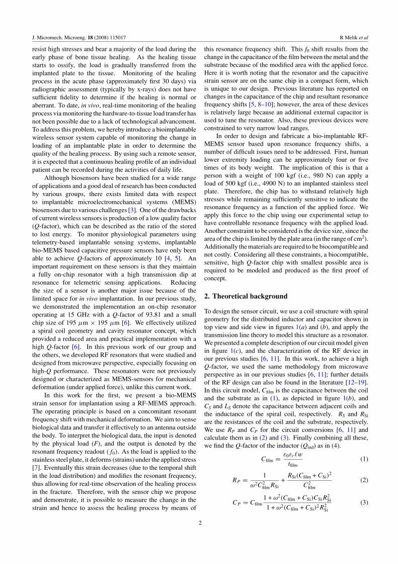
resist high stresses and bear a majority of the load during theearly phase of bone tissue healing. As the healing tissuestarts to ossify, the load is gradually transferred from theimplanted plate to the tissue. Monitoring of the healingprocess in the acute phase (approximately first 30 days) viaradiographic assessment (typically by x-rays) does not havesufficient fidelity to determine if the healing is normal oraberrant. To date, in vivo, real-time monitoring of the healingprocess via monitoring the hardware-to-tissue load transfer hasnot been possible due to a lack of technological advancement.To address this problem, we hereby introduce a bioimplantablewireless sensor system capable of monitoring the change inloading of an implantable plate in order to determine thequality of the healing process. By using such a remote sensor,it is expected that a continuous healing profile of an individualpatient can be recorded during the activities of daily life.
Although biosensors have been studied for a wide rangeof applications and a good deal of research has been conductedby various groups, there exists limited data with respectto implantable microelectromechanical systems (MEMS)biosensors due to various challenges [3]. One of the drawbacksof current wireless sensors is production of a low quality factor(Q-factor), which can be described as the ratio of the storedto lost energy. To monitor physiological parameters usingtelemetry-based implantable sensing systems, implantablebio-MEMS based capacitive pressure sensors have only beenable to achieve Q-factors of approximately 10 [4, 5]. Animportant requirement on these sensors is that they maintaina fully on-chip resonator with a high transmission dip atresonance for telemetric sensing applications. Reducingthe size of a sensor is another major issue because of thelimited space for in vivo implantation. In our previous study,we demonstrated the implementation an on-chip resonatoroperating at 15 GHz with a Q-factor of 93.81 and a smallchip size of 195 μm × 195 μm [6]. We effectively utilizeda spiral coil geometry and cavity resonator concept, whichprovided a reduced area and practical implementation with ahigh Q-factor [6]. In this previous work of our group andthe others, we developed RF resonators that were studied anddesigned from microwave perspective, especially focusing onhigh-Q performance. These resonators were not previouslydesigned or characterized as MEMS-sensors for mechanicaldeformation (under applied force), unlike this current work.
In this work for the first, we present a bio-MEMSstrain sensor for implantation using a RF-MEMS approach.The operating principle is based on a concomitant resonantfrequency shift with mechanical deformation. We aim to sensebiological data and transfer it effectively to an antenna outsidethe body. To interpret the biological data, the input is denotedby the physical load (F), and the output is denoted by theresonant frequency readout (f0). As the load is applied to thestainless steel plate, it deforms (strains) under the applied stress[7]. Eventually this strain decreases (due to the temporal shiftin the load distribution) and modifies the resonant frequency,thus allowing for real-time observation of the healing processin the fracture. Therefore, with the sensor chip we proposeand demonstrate, it is possible to measure the change in thestrain and hence to assess the healing process by means of
this resonance frequency shift. This f0 shift results from thechange in the capacitance of the film between the metal and thesubstrate because of the modified area with the applied force.Here it is worth noting that the resonator and the capacitivestrain sensor are on the same chip in a compact form, whichis unique to our design. Previous literature has reported onchanges in the capacitance of the chip and resultant resonancefrequency shifts [5, 8–10]; however, the area of these devicesis relatively large because an additional external capacitor isused to tune the resonator. Also, these previous devices wereconstrained to very narrow load ranges.
In order to design and fabricate a bio-implantable RF-MEMS sensor based upon resonance frequency shifts, anumber of difficult issues need to be addressed. First, humanlower extremity loading can be approximately four or fivetimes of its body weight. The implication of this is that aperson with a weight of 100 kgf (i.e., 980 N) can apply aload of 500 kgf (i.e., 4900 N) to an implanted stainless steelplate. Therefore, the chip has to withstand relatively highstresses while remaining sufficiently sensitive to indicate theresonance frequency as a function of the applied force. Weapply this force to the chip using our experimental setup tohave controllable resonance frequency with the applied load.Another constraint to be considered is the device size, since thearea of the chip is limited by the plate area (in the range of cm2).Additionally the materials are required to be biocompatible andnot costly. Considering all these constraints, a biocompatible,sensitive, high Q-factor chip with smallest possible area isrequired to be modeled and produced as the first proof ofconcept.
2. Theoretical background
To design the sensor circuit, we use a coil structure with spiralgeometry for the distributed inductor and capacitor shown intop view and side view in figures 1(a) and (b), and apply thetransmission line theory to model this structure as a resonator.We presented a complete description of our circuit model givenin figure 1(c), and the characterization of the RF device inour previous studies [6, 11]. In this work, to achieve a highQ-factor, we used the same methodology from microwaveperspective as in our previous studies [6, 11]; further detailsof the RF design can also be found in the literature [12–19].In this circuit model, Cfilm is the capacitance between the coiland the substrate as in (1), as depicted in figure 1(b), andCS and LS denote the capacitance between adjacent coils andthe inductance of the spiral coil, respectively. RS and RSi
are the resistances of the coil and the substrate, respectively.We use RP and CP for the circuit conversions [6, 11] andcalculate them as in (2) and (3). Finally combining all these,we find the Q-factor of the inductor (Qind) as in (4).
Cfilm = ε0εr�w
tfilm(1)
RP = 1
ω2C2filmRSi
+RSi(Cfilm + CSi)
2
C2film
(2)
CP = Cfilm1 + ω2(Cfilm + CSi)CSiR
2Si
1 + ω2(Cfilm + CSi)2R2Si
(3)
2

J. Micromech. Microeng. 18 (2008) 115017 R Melik et al
(a) (b) (c)
Figure 1. (a) The top-view micrograph of a fabricated resonator, (b) a side-view schematic of the resonator shown along with the lumpedelement representations of its physical model and (c) our equivalent circuit model of the resonator.
Qind = ωLS
RS
× 2RP
2RP +[(
ωLS
RS
)2+ 1
]RS
×[
1 − R2S
(CP
2 + CS
)LS
− ω2LS
(CP
2+ CS
)]. (4)
To determine the change in the resonant frequency readoutwe start from the force (F) and stress (σ ) relationship. Whena force is applied to the structure, it creates stress as givenin (5), where A denotes the cross-sectional area of the plate.The stress causes strain (ε) in the structure as in (6), wherethe strain is calculated from the relationship in (7). E and lrepresent the Young’s modulus (Pa) and length of the plate,respectively. The strain changes the sensor behavior mainlyas a result of the modification in the capacitance. As a resultwe observe a change in the resonance frequency. We apply apoint load to our structure to mechanically deform the activedevice area with the applied load. As we already know theparameters of the deflection, we determine our controllableload from (8) [20]. Here x, y and L represent the positionsalong beam length, the deflection and the beam length (m),respectively. I is the moment of inertia (m4).
σ = F
A(5)
σ = Eε (6)
ε = �l
l(7)
y(x) = F
6EI(3x2L − x3). (8)
3. Sensor design and fabrication
With the aim of designing a biocompatible, high Q-factorsensor resonator chip with a small size and high frequencyshift, we first need to determine the circuit that measures thechange in the resonance frequency to operate either in a passiveor active mode. In the case of an active circuit, minimizationof the circuit space is restricted by the power supply and thedevice size becomes larger with a limited deformation of thedevice. Therefore, we prefer to use a passive circuit. Althoughusing GaAs as the substrate material would enhance the Q-factor, we use Si for its better biocompatibility characteristics.
Nonconductive Si hinders the parallel plate capacitance andthe proper operation of the resonator. On the other hand,conductive Si decreases the Q-factor. Therefore, we employ ahighly resistive Si substrate.
The selection of the dielectric layer affects the capacitanceand the Q-factor. Si3N4 has a relatively high dielectric constant(as high as 8) and low loss, and also it is biocompatible.There are some dielectric materials that feature lower Young’smoduli than Si3N4; however, they have higher loss and lowerdielectric constants, resulting in a low Q-factor and the changeof resonance frequency would not be as high as that of Si3N4.As a result, considering the trade-off between high Q-factor,small dimensions and high shift of resonance frequency, weselect Si3N4 as the dielectric layer.
To observe the change in the resonance frequency (�f0)
easily, we need to have a sufficiently low Young’s modulusof the dielectric material as given in (6) since the stress isset to a fixed value and Young’s moduli of Si and metal arealready high. Therefore, when the area of the dielectric layeris changed, the capacitance is modified as in (1) and we realizea shift in the resonance frequency, which also affects the Q-factor as in (4). In the case of metals, their Young’s moduli arenearly the same, which means that the choice of the metal istrivial for the shift of resonance frequency. Although Al and Cuare mostly utilized as metal layers, they are not biocompatible.Therefore, for future in vivo applications in mind, we prefer touse Au as the metal layer.
When deciding on the film thickness, once again we arerequired to consider the critical constraints such as a high Q-factor and small allowable dimension. Thus, our approach isto favor the high capacitance, which can be obtained from thetank circuit capacitance [6, 11] as opposed to considering thiselement as a parasitic capacitance (as it has been previouslytypically treated by other research groups). Hence, we choosea film thickness (tfilm) as low as 0.1 μm. Using the filmcapacitance for self-tuning the resonator will also increase theresonance frequency shift and improve the sensor sensitivitycompared to the approach of using an external capacitor fortuning.
To realize a high-performance sensor, the width of themetal is a critical design issue because an increase in the widthwould also increase the Q-factor and the resonance frequency,but this would produce an associated increase in the areaat the same time. Therefore, considering these constraints,we choose an optimal value for the width. Also the metal
3

J. Micromech. Microeng. 18 (2008) 115017 R Melik et al
Figure 2. Illustration of the deformed device when a load of 1960 N is applied from the bottom. The area and the thickness of the device arefixed to 340 μm × 340 μm and 500 μm, respectively. The z-direction is scaled down by a factor of 10 for a better view of the image.
spacing affects the device performance. A lower spacingincreases resonance frequency and leads to a more compactchip. However, an increased width and decreased spacing leadto parasitic effects which would decrease the Q-factor. So thevalue of the spacing should be carefully adjusted. With ourdesign methodology, we find that we do not need to considerthe effect of the skin depth, as this effect is relatively reducedand high Q-factors are still obtained; the derivation of thisconclusion can be found elsewhere [11].
Increasing the number of turns of the coil decreases theQ-factor and the resonance frequency and increases the areaof the chip. Two turns is the minimum number needed toproduce a full coil and this is the geometry used in our design.Decreasing the total area leads to an improved Q-factor anda higher resonance frequency. Also, a smaller inner diameterincreases the Q-factor and resonance frequency. However,decreasing the inner diameter to a point where it is less thanthe spacing causes additional parasitic effects. Therefore,considering the width, the spacing, the inner diameter andthe number of turns, we choose an optimal area. Rp, whichwas given in (2), represents the combined resistance of our coilmodel and is an effective component to determine the substratelosses. We choose a high-resistivity substrate to get a high RSi
and thus a high RP. Therefore, in our model, the substrateloss factor is nearly independent of the frequency, and also,we obtain a high Q-factor. Cp, corresponding to the capacitivecomponent of the combined impedance and calculated as in(3), has a significant effect on the self-resonance factor. LowerCp results in an enhanced resonance frequency.
Taking all these different factors into account, we designedtwo sensor chips with the parameters determined as shown intable 1. Here LC and WC represent total length and total widthof the device, respectively. N is the number of turns, w is thewidth of each coil, and s is the spacing between coils. Alsotfilm and tmetal represent the thickness of the dielectric film andthe thickness of the metal, respectively.
Based on the parameters of sensor-1, we ran a simulationusing a commercially-available finite element softwarepackage (Coventorware) to monitor the strain induced inthe device when a load of 1960 N is applied. Figure 2 shows
Table 1. Our device parameters.
Lc Wc w s tfilm tmetal
(μm) (μm) N (μm) (μm) (μm) (μm)
Sensor-1 340 340 2 60 10 0.1 0.1Sensor-2 270 270 2 50 5 0.1 0.1
Table 2. The theoretical and numerical LS values for sensor-1 andsensor-2.
Theoretical NumericalLS (nH) LS (nH)
Sensor-1 2.854 2.842Sensor-2 2.260 2.244
the resulting displacement field. From the simulation, weobserve that the area of the dielectric film changes, modifyingthe value of Cfilm. We note that the change in the area is notuniform, which results in a nonlinear change in Cfilm, and thus,in the resonance frequency, as a function of the applied load(where the resonance frequency is calculated from the pointthat Qind becomes zero as in (4)).
We numerically calculated the inductance of the spiral coil(Ls), which is obtained by the addition of self-inductance withthe positive mutual inductance and subtracted by the negativemutual inductance. We observe a very good agreement withthe results obtained by the MemHenry suite of Coventorware(table 2).
We fabricate our sensors using standard MEMSfabrication processes. For fabrication, the substrate is initiallypatterned with lithography and metallization is performed toobtain a thickness of 0.1 μm using Au. Then the structureis coated by a 0.1 μm thick Si3N4 layer using PECVD.Patterning is realized with lithography and holes are openedusing wet etching by HF. The open parts are metallized with theboxcoater at a thickness of 0.1 μm (Au). Finally, the shape ofthe device is given by a third lithography step and the processis completed with a 0.1 μm thick Au metallization. Thefabricated device is presented in the inset of figure 3(a).
4

J. Micromech. Microeng. 18 (2008) 115017 R Melik et al
(a) (b)
(c)
Figure 3. (a) The experimental setup along with the fabricated sensor in the inset, (b) the cross-sectional sketch of our experimental setupand its components and (c) illustration of the mechanical deformation when the force is applied.
4. Experimental characterization
The experimental characterization consists of applying a pointload in a controlled manner (figure 3). We use two thin clampsat the edges to fix the silicon substrate as shown in figures 3(a)and (b). There is a hole in the middle and we placed the siliconsubstrate into this aperture, fixing the substrate to the edges ofthe experimental apparatus sketched in figure 3(b). We usedthe screw below the silicon substrate to control and modify theload in a controllable manner. We used an ultra fine adjustablescrew so that we could easily modify the applied load. The tipof the screw is a critical part as it should not penetrate orcause failures in the silicon substrate when applying highloads. After fixing our substrate, we measure S21 parametersof our device with microwave probes as presented infigures 3(a) and (b). When we apply load to the whole chipby using screw, a point load is applied to our device while itdeforms on the chip as shown in figure 3(c).
In figures 4(a) and (b), S21 parameters (in dB) are givenas a function of the frequency for sensor-1 and sensor-2,respectively. In figures 4(c) and (d) magnified views ofthe resonance regions are shown for sensor-1 and sensor-2,respectively. One can clearly see the differences between
Table 3. The resonance frequencies of the sensors with thechanging load values.
Load No load 1960 N 2940 N 3920 N
Sensor-1 11.48 GHz 11.72 GHz 11.78 GHz 11.81 GHzSensor-2 13.59 GHz 13.84 GHz 13.91 GHz 13.95 GHz
the sensor responses without any deformation (no load) andthen also with deformation. In the case of no deformationfor sensor-1, the resonance frequency was measured to be11.48 GHz, also given in table 3, with a Q-factor of 59.98.When we apply 1960 N, the resonance frequency changes to11.72 GHz, indicating a 240 MHz shift (also summarized intable 4). When we apply a load of 2940 N, the resonancefrequency increases to 11.78 GHz and for 3920 N, it becomes11.81 GHz (table 3). Therefore, for a load of 2940 N, weobtain a shift of 2940 MHz and for 3920 N, a shift of 330 MHzin the resonance frequency as compared to the initial condition(table 4). Also, the Q-factor of the sensor changes from 59.98to 70.35 when 1960 N load is applied. For a load of 2940 N,the Q-factor is 74.32 and for 3920 N, the Q-factor is 76.00(table 5).
5

J. Micromech. Microeng. 18 (2008) 115017 R Melik et al
(a) (b)
(c) (d )
Figure 4. Experimental measurements of S21 parameters as a function of frequency for (a) sensor-1 and (b) sensor-2, along with theirzoom-in resonance regions for (c) sensor-1 and (d) sensor-2, respectively, for the cases without deformation and when loads of 1960 N,2940 N and 3920 N are applied.
Table 4. The shift of resonance frequencies of the sensors with thechanging load values.
Load 1960 N 2940 N 3920 N
Sensor-1 240 MHz 300 MHz 330 MHzSensor-2 250 MHz 320 MHz 360 MHz
Table 5. Q-factors with the changing load values.
Load No load 1960 N 2940 N 3920 N
Sensor-1 59.98 70.35 74.32 76.00Sensor-2 69.91 87.87 89.22 95.39
Figure 4(b) shows S21 parameter of sensor-2 in decibelsas a function of the frequency. Similar to sensor-1, theresonance frequency increases with the applied load. For theno-deformation case, the resonance frequency is 13.59 GHz(table 3) and the Q-factor is 69.91 (table 5). After theapplication of 3920 N load, the resonance frequency becomes13.95 GHz, representing a resonance frequency shift of360 MHz (table 4) with a Q-factor of 95.39. For 1960 N a13.84 GHz resonance frequency was measured (table 3) withan 87.87 Q-factor (table 5).
From these experimental results it is clear that theresonance frequency increases with the applied load. Thiscan be explained theoretically by the decrease in the area,
and hence the resulting decrease in the capacitance (figure 2),leading to an increase in the resonance frequency with theapplied load. We also observe that the shift is not linear withrespect to the applied load and thus the induced strain (which isexperimentally obtained in the reference strain measurementsusing high-quality semiconductor based wired strain gauges,made by Kyowa, Japan, with a gauge factor of 178) (figure 5).The decrease in the area of the capacitance is not linear so thechange in the capacitance is not linear and also capacitanceaffects the resonance frequency nonlinearly as in (4), and,accordingly, our observation that the change in the resonancefrequency is nonlinear with the applied load is congruent withour theoretical derivation.
We can consider the shift of resonance frequency fromother perspectives. For example, we can define sensitivitywith respect to the applied force as �f0
F. Since we have
similar geometries in sensor-1 and sensor-2, which are bothrectangular, and they are fabricated with the same fabricationprocedure, they are expected to have nearly the same levelof sensitivity. For sensor-1 we have 330 MHz resonancefrequency shift with 3920 N of applied load. So we have0.0842 MHz N−1 sensitivity. For sensor-2 we have 360 MHzresonance frequency shift with 3920 N of applied load, andhence, 0.0918 MHz N−1 sensitivity. The sensor with a higherf0 will have a higher sensitivity since a higher frequency meansa slightly higher shift. Also, we can define sensitivity withrespect to the induced strain as �f0
ε. Because of the structure
6

J. Micromech. Microeng. 18 (2008) 115017 R Melik et al
(a) (b)
Figure 5. Resonance frequency (f0) as a function of the externally applied load and the induced strain (microstrain) (a) for sensor-1 and(b) for sensor-2.
of our load setup, which is explained in detail and illustratedin figure 2, the minimum strain that we can reproducibly applyis 81.5 microstrain, while the maximum strain that we cancontrollably apply is 172.8 microstrain. For sensor-1 wehave 330 MHz resonance frequency shift with an inducedstrain of 172.8 microstrain while we have 360 MHz resonancefrequency shift with 172.8 microstrain for sensor-2. So forsensor-1, we have 1.9 MHz/microstrain sensitivity while wehave 2.1 MHz/microstrain sensitivity for sensor-2. Similarto the sensitivity defined with respect to the applied load,the sensor with higher f0 expectedly yields a slightly highersensitivity also with respect to strain. For another comparison,we can use another definition: relative shift, which is �f0
f0at a
given applied load. For sensor-1, under 3920 N, we have a shiftof 330 MHz at 11.48 GHz resonance frequency; thus we have arelative shift of 2.88%. For sensor-2 we have 360 MHz shift at13.59 GHz resonance frequency; thus we have a relative shiftof 2.65%. From these results, we observe that we have nearlythe same sensitivities and relative shifts. Also, theoreticallywe consider that if two sensors exhibit the same relative shift,the sensor that has a higher resonance frequency will havea higher change of resonance frequency, and hence a highersensitivity. Experimentally, we find out that although sensor-2has a slightly lower relative shift compared to sensor-1, sensor-2 has a slightly higher sensitivity. Presently, by exploringdifferent geometries, different fabrication procedures anddifferent operating frequencies, we are working on increasingthe sensitivity and relative shift.
Another important conclusion of our experiments is thatthe Q-factor of the device is different for each appliedload and the resulting strain, as was predicted theoretically.The increase is shown in figure 6. When LC decreases, theresonance frequency and the Q-factor are increased while thearea decreases, as calculated in (4). Therefore, it is expectedthat sensor-2 has a higher resonance frequency and Q-factorcompared to sensor-1. When the capacitance is decreased,the Q-factor is improved as calculated from (4). Therefore,experimentally we observe an increase both in the resonancefrequency and the Q-factor as shown in figure 6. Also, since thecapacitance change is not linear with applied load and changeof the capacitance affects the Q-factor nonlinearly from (4),
Figure 6. Q-factor as a function of the applied load and the inducedstrain (microstrain) for sensor-1 (top) and for sensor-2 (bottom).
Figure 7. A plan-view micrograph of our fabricated 270 μm × 270μm on-chip sensor along with the on-chip antennas forcommunication.
the Q-factor change is theoretically expected to be nonlinearwith the applied load. From table 5, we also experimentallyobserve that the increase in the Q-factor with applied load isnot fully linear.
There is a strong demand for implantable chips thatmeasure the change in hardware stress without any externalwiring. This would allow the treating clinician to remotelymeasure and report the information. Therefore, to verify thewireless performance of our sensor, we utilized a telemetry-based implantable sensing system to monitor the resonantfrequency shift as a function of the physical load (figure 7).This system consists of two antennas on the chip to serve as
7

J. Micromech. Microeng. 18 (2008) 115017 R Melik et al
Figure 8. Experimental measurement of S21 parameters for thesensor under different loads taken by using the transmitter andreceiver antennas.
external antennas. Between these antennas there is the deviceunder test used as the sensor. The telemetric sensor and theantennas have the same dimensions as those of sensor-2.
Similar to the previous cases, we detected strain bymeasuring the resonance frequencies of the system withoutany applied load and after applying different loads to thesensor chip. By using three similar resonators, we set up atelemetric system on the same chip. The S21 parameter isplotted as a function of the frequency in figure 8. Just likethe previous cases, the area of the chip decreases and theresonance frequency increases with the applied load. Withoutdeformation, the resonance frequency and the Q-factor werefound to be 13.71 GHz and 38, respectively. After applyinga 3920 N, the resonance frequency and the Q-factor wasmeasured to be 13.9 GHz and 46, respectively, representing aresonance frequency shift of 190 MHz.
5. Conclusions
We designed, fabricated and experimentally characterized ahigh Q-factor, bio-implantable RF-MEMS strain sensor tomonitor the fracture healing process by measuring the changein the strain. Such a sensor of our design can withstand loadsup to 3920 N without deterioration in the Q-factor, even forchip areas smaller than 0.1 mm2. When a load of 3920 Nis applied to the sensor with an area of 340 μm × 340 μm(sensor-1), the resonance frequency is shifted by 330 MHzand the Q-factor is increased from ∼60 to ∼76. As the areais decreased to 270 μm × 270 μm (sensor-2), we observethat the resonance frequency shift becomes 360 MHz and theQ-factor is increased from ∼70 to ∼95. We both theoreticallyand experimentally showed that our sensors can be utilized forassessing the osseous fractures through monitoring the shift inthe resonance frequency. We also showed that our approachcan be modified to work telemetrically. By fabricating threedevices, one sensor and two antennas on the same chip, toset up a telemetric system, we demonstrated that the wirelessmeasurement of the resonant frequency shift is possible. In thiscase, the resonance frequency and the Q-factor are increasedwhen a load is applied. As a result of this pilot study, we believethat, by observing the change in resonance frequency, surgeons
can evaluate the fracture healing process longitudinally. Thispaper is the first theoretical and experimental proof of thisconcept. For human implantation applications, the resonancefrequency needs to be shifted to a lower range where absorptionbecomes less considerable. Our future research directions willinclude improving our sensor to operate within the constraintsof the implantation applications.
Acknowledgment
This work is supported by the European Science Foundation(ESF) European Young Investigator Award (EURYI) and theTurkish National Academy of Sciences (TUBA) DistinguishedYoung Scientist Award (GEB_IP), and TUB_ITAK EEEAG105E066, 105E065, 104E114, 106E020, 107E088 and107E297, and EU IRG MOON 021391. We are pleasedto acknowledge M Yorulmaz for his assistance in usingCoventorware, Dr A Dana and E Karaman for their help inthe construction of our experimental setup, and Dr Z Dilli forfruitful discussions with her.
References
[1] Schuylenbergh K V, Puers R, Rodes F, Burny F, DonkenvolckeM and Moulart F 1992 Monitoring orthopaedic implantsusing active telemetry Proc. Ann. Int. Conf. IEEE 6 2672–3
[2] Einhorn T A 1995 Enhancement of fracture healing J. BoneJoint Surg. 77 940–56
[3] Grayson A C R, Shawgo R S, Johnson A M, Flynn N T, Li Y,Cima M J and Langer R A 2004 BioMEMS review: MEMStechnology for physiologically integrated devices Proc.IEEE 92 6–21
[4] Simons R N and Miranda F A 2005 Radiation characteristicsof miniature silicon square spiral chip antenna forimplantable bio-MEMS sensors Antennas and PropagationSoc. Int. Symp., IEEE vol 1B pp 836–9
[5] Simons R N, Hall D G and Miranda F A 2004 RF Telemetrysystem for an implantable Bio-MEMS sensor IEEE MTT-SInter. Microwave Symp. Digest vol 3 pp 1433–6
[6] Melik R, Perkgoz N K, Unal E, Dilli Z and Demir H V 2008Design and realization of a fully on-chip high-Q resonatorat 15 GHz on silicon IEEE Trans. Electron Dev. in press
[7] Stoffel K, Klaue K and Perren S M 2000 Functional load ofplates in fracture fixation in vivo and its correlate in bonehealing Injury 31 37–50
[8] Simons R N, Hall D G and Miranda F A 2004 Spiral chipimplantable radiator and printed loop external receptor forRF telemetry in bio-sensor systems Radio and WirelessConf., IEEE pp 203–6
[9] Miranda F A, Simons R N and Hall D G 2004 Validation ofradio frequency telemetry concept in the presence ofbiological tissue-like stratified media IEEE Antennas andPropagation Society Inter. Symp. Digest vol 2 pp 1335–8
[10] Simons R N and Miranda F A 2003 Radio frequency telemetrysystem for sensors and actuators US Patent 6667725
[11] Melik R and Demir H V 2008 Implementation of highquality-factor on-chip tuned microwave resonators at 7 GHzMicrow. Opt. Technol. Lett. in press
[12] Yue C P and Wong S S 1998 On-chip spiral inductors withpatterned ground shields for Si-based RF IC’s IEEE J.Solid-State Circuits 33 743–52
[13] Bahl I 2003 Lumped Elements for RF and Microwave Circuits(London: Artech House)
8

J. Micromech. Microeng. 18 (2008) 115017 R Melik et al
[14] Collin R E 1992 Foundations for Microwave Engineering(New York: McGraw Hill)
[15] Pozar D M 2005 Microwave Engineering (New York: Wiley)[16] Greenhouse H M 1974 Design of planar rectangular
microelectronic inductors IEEE Trans. Parts HybridsPackag. 10 101–9
[17] Lee T H 1998 The Design of CMOS Radio-FrequencyIntegrated Circuits (New York: Cambridge UniversityPress)
[18] Yue C P, Ryu C, Lau J, Lee T H and Wong S S 1996A physical model for planar spiral inductorson silicon IEEE Int. Electron Dev. Meetingpp 155–8
[19] Koutsoyannopoulos Y K and Papananos Y 2000 Systematicanalytic and modeling of integrated inductors andtransformers in RFIC design IEEE Trans. Circuits Syst.47 699–713
[20] Senturia S D 2001 Microsystem Design (Kluwer: Academic)
9