BILLY GOAT BC2600 Hydro Series Brush Cutter Owner's Manual
26
Part No 501505 1 Form No F041513A BILLY GOAT ® BC2600 Hydro Series Brush Cutter Owner’s Manual
Transcript of BILLY GOAT BC2600 Hydro Series Brush Cutter Owner's Manual

Part No 501505 1 Form No F041513A
BILLY GOAT ® BC2600 Hydro Series Brush Cutter
Owner’s Manual

Part No 501505 2 F041513A
BC2600 Hydro Series Brush Cutter Owner’s Manual
CONTENTS Specifications and Sound/Vibration .................................................................................................................. 3 Instruction Labels .............................................................................................................................................. 4 Assembly Instructions ....................................................................................................................................... 5-6 Operation ........................................................................................................................................................... 7-9 Maintenance ...................................................................................................................................................... 10-16 Battery maintenance ………………………………………………………………………………………………………17 Troubleshooting ................................................................................................................................................. 18 Illustrated Parts List ........................................................................................................................................... 19-26
Go to http://www.billygoat.com for French-Canadian translations of the product manuals.
Visitez http://www.billygoat.com pour la version canadienne-française des manuels de produits

Part No 501505 3 F041513A
BC2600 Hydro Series Brush Cutter Owner’s Manual
BC 2600 SERIES SPECIFICATIONS
BC2600ICH BC2600HH BC2600HEBH
Engine Type Briggs and Stratton
Honda GX390 Honda Electric
Model Number 219972 0151 F! GX390UT2 DABG V390UTDE33
Displacement 344 cc 390 cc 390 cc
Fuel Capacity 3.0 qt (2.80 L) 3.0 qt (2.80 L) 2.3 qt (2.18L)
Oil Capacity 1.5 qt (1.4L) 1.5 qt (1.4L) 1.2 qt (1.13L)
Unit Weight 325 lb (147.4 kg) 325 lb (147.4 kg) 335 lb (152 kg)
Overall Length 72 in (1.83 m)
Overall Width 31 in (0.78 m)
Overall Height 48 in (1.21 m)
Maximum Operating Slope
15o 20
o 20
o
SOUND DATA
SOUND LEVEL 91.6 Dba at Operator’s position
Sound tests were conducted in accordance with 2000/14/EEC and were performed on 11/30/11 under the conditions listed below.
Sound power level listed is the highest value for any model covered in this manual. Please refer to serial plate on the unit for the sound power level for your model.
General Conditions: Sunny Temperature: 47
oF (8.3
oC)
Wind Speed: 9 mph (14.5 kph) Wind Direction: South Humidity: 25% Barometric Pressure: 30.07” Hg (101.83 kPa)
VIBRATION DATA
VIBRATION LEVEL .3g (3.13 m/s2)
Vibration levels at the operator’s handles were measured in the vertical, lateral and longitudinal directions using calibrated vibration test equipment. Tests were performed on 11/30/11 under the conditions listed below. General Conditions: Sunny Temperature: 47
oF (8.3
oC)
Wind Speed: 9 mph (14.5 kph) Wind Direction: South Humidity: 25% Barometric Pressure: 30.07” Hg (101.83 kPa)
112 dB
Part No 501505 4 F041513A
BC2600 Hydro Series Brush Cutter Owner’s Manual
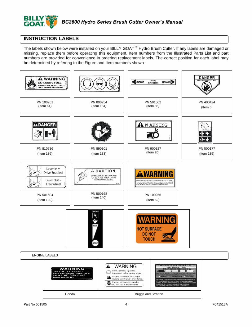
INSTRUCTION LABELS
The labels shown below were installed on your BILLY GOAT
® Hydro Brush Cutter. If any labels are damaged or
missing, replace them before operating this equipment. Item numbers from the Illustrated Parts List and part numbers are provided for convenience in ordering replacement labels. The correct position for each label may be determined by referring to the Figure and Item numbers shown.
PN 100261 (Item 61)
PN 890254 (Item 134)
PN 810736
(Item 136)
PN 890301
(Item 133)
PN 900327 (Item 20)
PN 500177
(Item 135)
PN 501502 (Item 85)
PN 400424
(Item 5)
PN 501504
(Item 139)
PN 500168 (Item 140)
PN 100256
(Item 62)
Honda Briggs and Stratton
ENGINE LABELS
Part No 501505 5 F041513A
BC2600 Hydro Series Brush Cutter Owner’s Manual
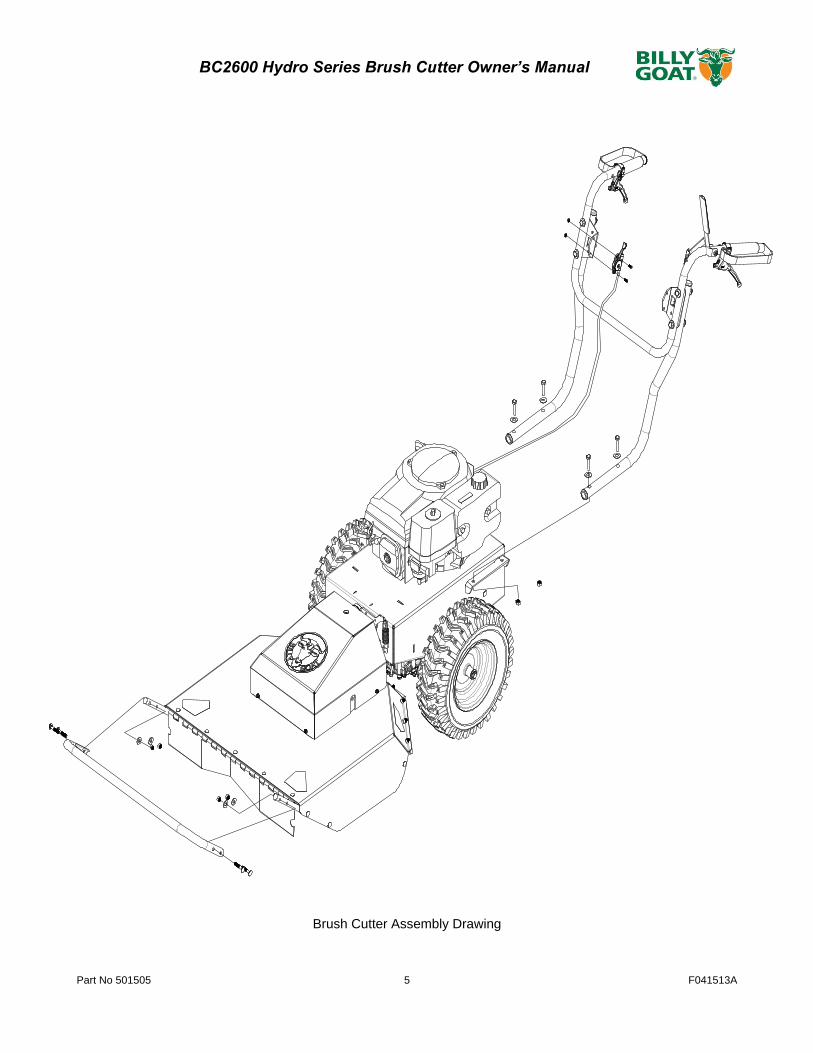
Brush Cutter Assembly Drawing
Part No 501505 6 F041513A
BC2600 Hydro Series Brush Cutter Owner’s Manual
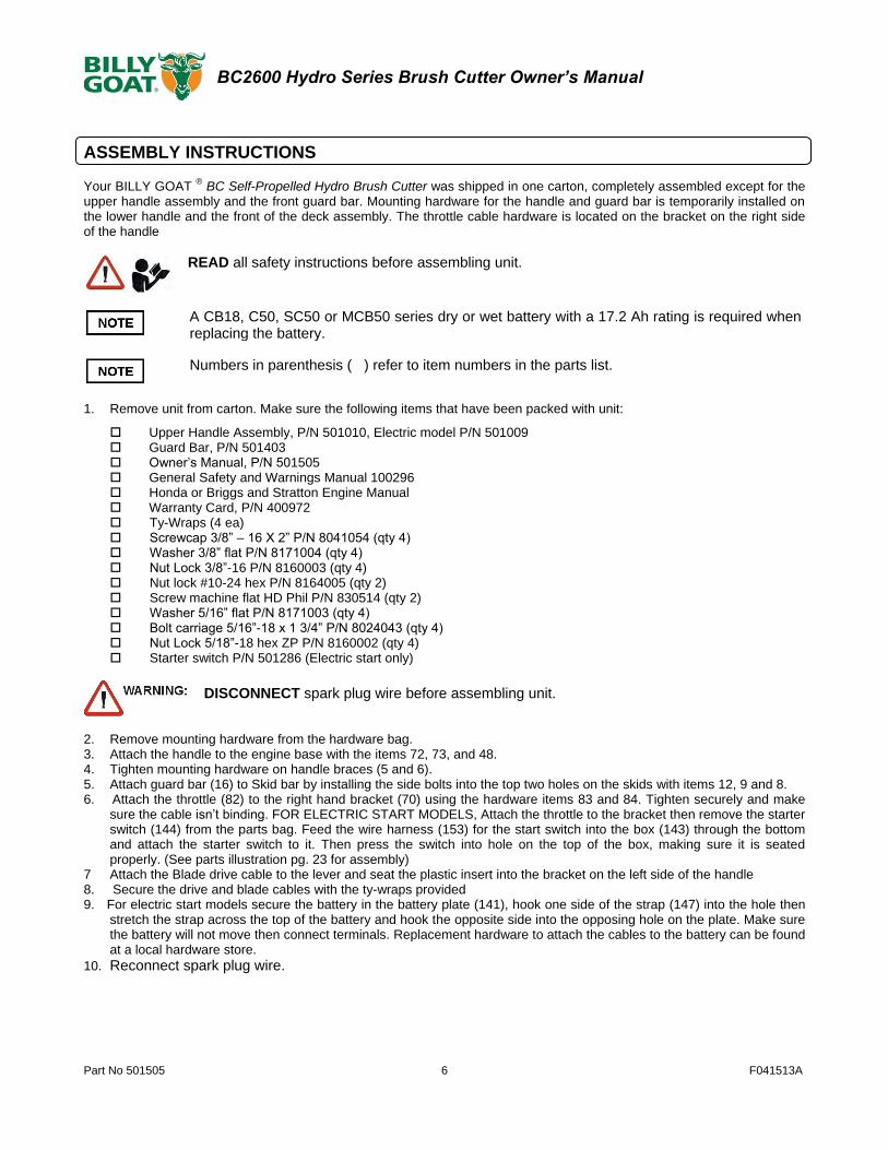
ASSEMBLY INSTRUCTIONS Your BILLY GOAT
® BC Self-Propelled Hydro Brush Cutter was shipped in one carton, completely assembled except for the
upper handle assembly and the front guard bar. Mounting hardware for the handle and guard bar is temporarily installed on the lower handle and the front of the deck assembly. The throttle cable hardware is located on the bracket on the right side of the handle
READ all safety instructions before assembling unit.
A CB18, C50, SC50 or MCB50 series dry or wet battery with a 17.2 Ah rating is required when replacing the battery.
Numbers in parenthesis ( ) refer to item numbers in the parts list.
1. Remove unit from carton. Make sure the following items that have been packed with unit:
Upper Handle Assembly, P/N 501010, Electric model P/N 501009 Guard Bar, P/N 501403 Owner’s Manual, P/N 501505 General Safety and Warnings Manual 100296 Honda or Briggs and Stratton Engine Manual Warranty Card, P/N 400972 Ty-Wraps (4 ea) Screwcap 3/8” – 16 X 2” P/N 8041054 (qty 4) Washer 3/8” flat P/N 8171004 (qty 4) Nut Lock 3/8”-16 P/N 8160003 (qty 4) Nut lock #10-24 hex P/N 8164005 (qty 2) Screw machine flat HD Phil P/N 830514 (qty 2) Washer 5/16” flat P/N 8171003 (qty 4) Bolt carriage 5/16”-18 x 1 3/4” P/N 8024043 (qty 4) Nut Lock 5/18”-18 hex ZP P/N 8160002 (qty 4) Starter switch P/N 501286 (Electric start only)
DISCONNECT spark plug wire before assembling unit.
2. Remove mounting hardware from the hardware bag. 3. Attach the handle to the engine base with the items 72, 73, and 48. 4. Tighten mounting hardware on handle braces (5 and 6). 5. Attach guard bar (16) to Skid bar by installing the side bolts into the top two holes on the skids with items 12, 9 and 8. 6. Attach the throttle (82) to the right hand bracket (70) using the hardware items 83 and 84. Tighten securely and make
sure the cable isn’t binding. FOR ELECTRIC START MODELS, Attach the throttle to the bracket then remove the starter switch (144) from the parts bag. Feed the wire harness (153) for the start switch into the box (143) through the bottom and attach the starter switch to it. Then press the switch into hole on the top of the box, making sure it is seated properly. (See parts illustration pg. 23 for assembly)
7 Attach the Blade drive cable to the lever and seat the plastic insert into the bracket on the left side of the handle 8. Secure the drive and blade cables with the ty-wraps provided 9. For electric start models secure the battery in the battery plate (141), hook one side of the strap (147) into the hole then
stretch the strap across the top of the battery and hook the opposite side into the opposing hole on the plate. Make sure the battery will not move then connect terminals. Replacement hardware to attach the cables to the battery can be found at a local hardware store.
10. Reconnect spark plug wire.

Part No 501505 7 F041513A
BC2600 Hydro Series Brush Cutter Owner’s Manual
OPERATION
OPERATOR CONTROLS The operator’s station is at the rear of the machine between the handlebars. The operator should STAND in a position to allow both handlebars to be grasped firmly and which allows sufficient leverage to steer the machine. Operator’s controls are shown below.
Operator Control Locations
1 Blade Clutch Lever 5 Start Switch (Electric only) 2 Forward Lever 6 Pull Starter 3 Reverse Lever 7 Choke 4 Throttle
STARTING
CHECK engine oil level before operating machine.
1. Place equipment on a level, firm surface that is free of rocks or other debris.
2. Place throttle in Fast position.
Throttle
3. Pull choke out (Honda engine only).
Choke
1
23
67
4

Part No 501505 8 F041513A
BC2600 Hydro Series Brush Cutter Owner’s Manual
4. Units equipped with electric starters: Turn the switch right until engine starts, only cranking over the engine for 10 sec at a time if it does not immediately start.
Start/Stop switch
DO NOT START equipment with drive or blade clutch engaged.
5. Units equipped with manual starters: Pull starter rope to start engine.
PULL STARTER CORD slowly until resistance is felt. Then pull cord rapidly to avoid kickback.
6. Push choke in (Honda engine only).
7. Pull throttle control back to and allow engine to reach correct operating speed.
CUTTING
The best performance is achieved when cutting in dry conditions. The quality of the cut is directly related to ground speed during cutting. Under most conditions cutting should be done at a slower ground speed. Fast speeds should be reserved for conditions where weeds and brush are thinned out or not very tall. If the quality of the cut is not satisfactory, attempt at slower speeds.
1. Press blade clutch handle down to engage blade. Allow blade to spin up to normal operating speed.
Blade Clutch Lever

Part No 501505 9 F041513A
BC2600 Hydro Series Brush Cutter Owner’s Manual
2. Pull Forward or Reverse Drive lever up to engage transaxle in desired direction.
Reverse Drive Lever (left hand) Forward Drive Lever (right hand)
SHUT DOWN 1. Release drive lever to disengage transaxle.
2. Release blade clutch handle to disengage blade.
3. (Non-Electric) Move the throttle to the slowest possible position on the throttle control.
4. (Electric models) Turn the key to the OFF position.
CLEARING A CLOGGED CUTTING DECK
1. Shut engine off and wait for blade to stop completely.
2. Disconnect spark plug wire.
3. Remove clog from cutting deck.
WEAR durable gloves. Clog may contain sharp materials.
4. Reconnect spark plug wire.
DISCONNECT spark plug wire before servicing unit.

Part No 501505 10 F041513A
BC2600 Hydro Series Brush Cutter Owner’s Manual
MAINTENANCE
PERIODIC MAINTENANCE Periodic maintenance should be performed at the following intervals:
Maintenance Operation Every Use Daily or Every 5 Hours
Every 25 Hours Every 50 Hours
Every 100-150 Hours
Inspect for worn or damaged parts.
Check for excessive vibration
Inspect for loose parts.
Sharpen blade.
Inspect belts for wear.
Lubricate throttle control cable and linkage.
Check blade clutch cable tension.
Inspect battery for corrosion, damage or leaks (electric start units only).
Apply anti-seize compound to rear axles.
Check battery strap for excessive wear or rips
Replace blade drive and transaxle drive belts.
COMMON REPLACEMENT PARTS - Blade. P/N 501224. Original equipment replacement blade.
- Transaxle Drive Belt. P/N 501268. Original equipment replacement drive belt.
- Blade Drive Belt. P/N 501220. Original equipment replacement drive belt.
- Skid. P/N 501407. Side deck skid.
- Throttle Control Assembly. Throttle control including cable.
CLEANING Your BILLY GOAT
® Brush Cutter should be cleaned periodically to ensure optimum performance and service life. Clogs and
debris should be removed from the blade area and debris should be removed from the engine cooling fins. A garden hose or pressure washer may be used for cleaning.
DO NOT SPRAY WATER DIRECTLY ON THE BLADE CLUTCH WHEN USING A POWER
WASHER. SEE FIGURE BELOW.

Part No 501505 11 F041513A
BC2600 Hydro Series Brush Cutter Owner’s Manual
BLADE REMOVAL AND SHARPENING
READ all safety instructions before servicing unit.
Numbers in parenthesis (N) refers to the item number in Illustrated Parts List.
DISCONNECT spark plug wire before servicing unit.
1. Disconnect spark plug wire.
2. Lift and support front of unit to allow access to underside.
UNIT IS HEAVY. Make sure support is adequate to support weight of machine.
3. Block blade to prevent it from rotating during removal.
4. Remove blade nut (23), and friction washer (39).
5. Remove blade (40) and install replacement blade.
When replacing the blade use BILLY GOAT Industries PN 501224 only.
6. Attach new blade with new blade lock nut (23), and new friction washer (39) removed earlier included with your new blade.
Inspect fasteners for wear and replace if necessary.
7. Torque blade lock nut to 30-40 ft-lbs.
8. Reconnect spark plug wire.
When sharpening blade make sure to sharpen all cutting edges. If the lock nut is removed and replaced more than once, it should be replaced with a new lock nut (P/N 8160009).

Part No 501505 12 F041513A
BC2600 Hydro Series Brush Cutter Owner’s Manual
BLADE DRIVE BELT TENSION
READ all safety instructions before servicing unit.
DISCONNECT spark plug wire before servicing unit.
The Blade Drive belt is under constant tension by the idler arm on the deck
1. Disconnect spark plug wire.
2. Loosen four screws (27) holding belt deck cover (29) and remove the cover.
3. Examine condition of belt and amount of tension on belt.
4. If the idler is not providing enough tension inspect the spring (item 50) attaching it to the spindle base. If not enough tension is being put on the arm, replace the spring.
7. Replace engine base door (29) and secure with screws removed earlier.
8. Reconnect spark plug wire.
9. Check belt tension by operating unit under conditions that caused belt slippage. If belt continues to slip it may require replacement before operation may continue.
BLADE CLUTCH ADJUSTMENT
READ all safety instructions before servicing unit.
DISCONNECT spark plug wire before servicing unit.
1. Disconnect spark plug wire.
2. As the clutch/brake wears or begins slipping or squealing, adjustment may be required to maintain proper cable tension and clutch engagement. A properly adjusted blade clutch should require 10 lbs. of force to depress the end of the clutch lever. The blade clutch cable spring should stretch 1/4” to 3/8” (6.4-9.5 mm).
3. Adjust cable tension by tightening or loosening cable adjustment nut on rear of engine base (see below). Be sure to leave enough slack in cable to allow blade brake to engage.
Blade Cable Adjustment
If clutch continues to slip or squeal, do not operate equipment until adequate adjustment or repair has been performed. Improper adjustment can cause clutch to overheat and slip, greatly reducing performance and clutch life.
4. Reconnect spark plug wire.

Part No 501505 13 F041513A
BC2600 Hydro Series Brush Cutter Owner’s Manual
TRANSAXLE DRIVE BELT REMOVAL AND REPLACEMENT
READ all safety instructions before servicing unit.
Numbers in parenthesis (N) refers to the item number in Illustrated Parts List.
DISCONNECT spark plug wire before servicing unit.
1. Disconnect spark plug wire.
2. Lift and support the rear of the unit to allow access to the underside
3. Unattach the spring (item 50) from the bracket (item 98) that is keeping tension on the drive belt.
4. Walk the belt (item 121) off of the clutch (item 54) by slowly pulling the engine over. WARNING: use caution not
to pinch fingers between the belt and clutch.
5. Slip the belt off of the transaxle pulley.
6. Replace the belt in reverse order. NOTE: make sure the belt is seated properly in the clutch and transaxle and
make sure that it does not bend over the fan blades on the transaxle.
BLADE DRIVE BELT REMOVAL AND REPLACEMENT
READ all safety instructions before servicing unit.
DISCONNECT spark plug wire before servicing unit.
1. Disconnect spark plug wire.
2. Lift and support rear of unit to allow access to underside.
UNIT IS HEAVY. Make sure support is adequate to support weight of machine.

Part No 501505 14 F041513A
BC2600 Hydro Series Brush Cutter Owner’s Manual
3. Loosen the four screws (27) holding deck belt cover (29) and remove cover.
4. Follow the steps 3 and 4 in the Transaxle drive belt removal section to remove the Transaxle drive belt.
It may be necessary to pry idler pulley (35) away from its original position to release belt, using a ratchet with an extension in the square hole on the idler arm should allow the proper leverage to pull it off the belt.
5. Relieve the tension on the blade belt by pulling the deck idler arm off of the belt. Then walk the belt off of the deck pulley.
6. Feed the belt back to the engine base then slip the belt off of the clutch.
7. Install the new belt in reverse order making sure the belt is seated properly in the clutch.
Removing tension on the blade belt
8. Reconnect spark plug wire.
LOOKING THROUGH TOP
Belt Routing Diagram (Top View of Machine)
Blade Drive Belt (with Transaxle Belt not Shown)
Transaxle Drive Belt (Seated below drive belt on clutch)

Part No 501505 15 F041513A
BC2600 Hydro Series Brush Cutter Owner’s Manual
TRANSAXLE DRIVE ADJUSTMENT
READ all safety instructions before servicing unit.
DISCONNECT spark plug wire before servicing unit.
1. Disconnect spark plug wire.
2. Adjustments to cable tension are made at the barrel entering the Drive Control Levers.
3. Adjust cable tension by tightening or loosening cable adjustment barrel on rear of engine base (see below).
Moving the cable adjustment barrel OUT increases tension. Moving the barrel IN decreases tension. Increasing the tension too much will cause the drive to stay engaged whereas not enough will cause it not to engage when the lever is pulled.
Transaxle Cable Adjustment 4. Reconnect spark plug wire.
DECREASE
INCREASE

Part No 501505 16 F041513A
BC2600 Hydro Series Brush Cutter Owner’s Manual
WIRING DIAGRAMS
Starter Switch Wiring
Starter Circuit Schematic Diagram
STARTER
MOTOR
RED
RED
GREEN/
YELLOW
BLACK
BLACK
BATTERY
ENGINE
GROUND
STARTER
SOLENOID
ENGINE
GROUND
FUSE20 A
M
G
L
S
WHITE
REDSWITCH

Part No 501505 17 F041513A
BC2600 Hydro Series Brush Cutter Owner’s Manual
Battery Care (For Electric-Starting Models) Proper care can extend the life of a battery. Follow these recommendations to ensure your battery’s best performance and long life:
• Do not allow the battery charge to get too low. If the machine is not used, charge the battery every 4
– 6 weeks. Operate the engine for at least 45 minutes to maintain proper battery charge.
• Store an unused battery in a dry area that does not freeze.
• Do not charge an already charged battery. In theory, you cannot overcharge our battery with a trickle
charger; however, when a battery is fully charged and the charger is still on, it generates heat that could be harmful to the battery. A fully charged battery will read 12V-13.2V with a voltmeter.
• Do not continue to crank your engine when the battery charge is low.
Charging the Battery Operate the engine for at least 45 minutes to maintain proper battery charge. If the battery loses its charge, you will need to use a trickle charger to recharge it. Caution: The charger should have an output of 12 volts at no more than 2 amps. Using a charger with higher amps will cause significant damage to the battery.
• At 1 amp, the battery may need charging for as long as 48 hours.
• At 2 amps, the battery may need charging for as long as 24 hours.
NOTE: Using the Recoil Starter and then running the engine will not recharge a dead or significantly discharged battery.
WHEN YOU ARE FINISHED CHARGING THE BATTERY, DISCONNECT THE CHARGER FROM THE OUTLET FIRST, THEN DISCONNECT THE BATTERY CHARGER WIRES FROM THE
BATTERY. IF YOU LEAVE THE BATTERY CHARGER WIRES CONNECTED TO THE BATTERY, THE BATTERY WILL DISCHARGE ITSELF BACK INTO THE CHARGER.

Part No 501505 18 F041513A
BC2600 Hydro Series Brush Cutter Owner’s Manual
TROUBLESHOOTING
Problem Possible Cause Corrective Action
Engine will not start. Throttle is set to Slow/Stop position. Move throttle to fast position.
Out of gasoline. Fill gas tank.
Old or contaminated gasoline. Drain gas tank and fill with fresh gasoline.
Spark plug wire disconnected. Connect spark plug wire.
Dirty air cleaner. Clean or replace air cleaner.
Starter does not turn.
(Electric start only)
Battery low or dead. Charge or replace battery.
Battery cable disconnected or corroded. Clean and secure battery terminals.
Defective starter switch or wiring harness. Replace starter switch or wiring harness.
Defective starter. Replace starter.
Blade drive cable tension incorrect. Adjust blade drive cable tension.
Will not cut or cutting performance is poor. Dull blade. Sharpen or replace blade.
Clogged deck. Unclog deck.
Excessive debris built up on or blocking blade.
Clear debris from blade area.
Engine RPM set too low. Check engine RPM.
Abnormal vibrations. Blade loose or out of balance. Check blade for tightness. Rebalance if necessary.
Engine loose. Check engine mounting bolts.
Blade drive belt worn. Replace blade drive belt.
Belt slips or smokes. Belt tension too low. Adjust belt tension.
Belt worn or stretched. Replace belt.
Pulleys worn or damaged. Replace pulleys.
Clutch slips or squeals. Clutch cable tension too low. Replace spring on idler arm.
Clutch worn or damaged. Replace worn or defective clutch assembly parts.
Blade brake will not engage. Inadequate slack in clutch cable. Adjust clutch cable.
Clutch worn or damaged. Replace clutch/brake assembly.
Transaxle will not engage. Clutch lever not engaging clutch. Adjust clutch cable.
Clutch cable defective. Replace cable.
Belt worn or broken. Replace belt.
Transaxle will not disengage. Clutch cable out of adjustment. Adjust clutch cable.
Engine will not turn over. Defective blade clutch. Replace clutch.
Engine problem. Contact an authorized servicing dealer for your engine.
Part No 501505 19 F041513A
BC2600 Hydro Series Brush Cutter Owner’s Manual
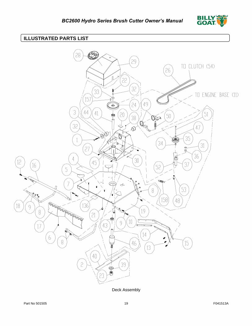
ILLUSTRATED PARTS LIST
Deck Assembly
Part No 501505 20 F041513A
BC2600 Hydro Series Brush Cutter Owner’s Manual
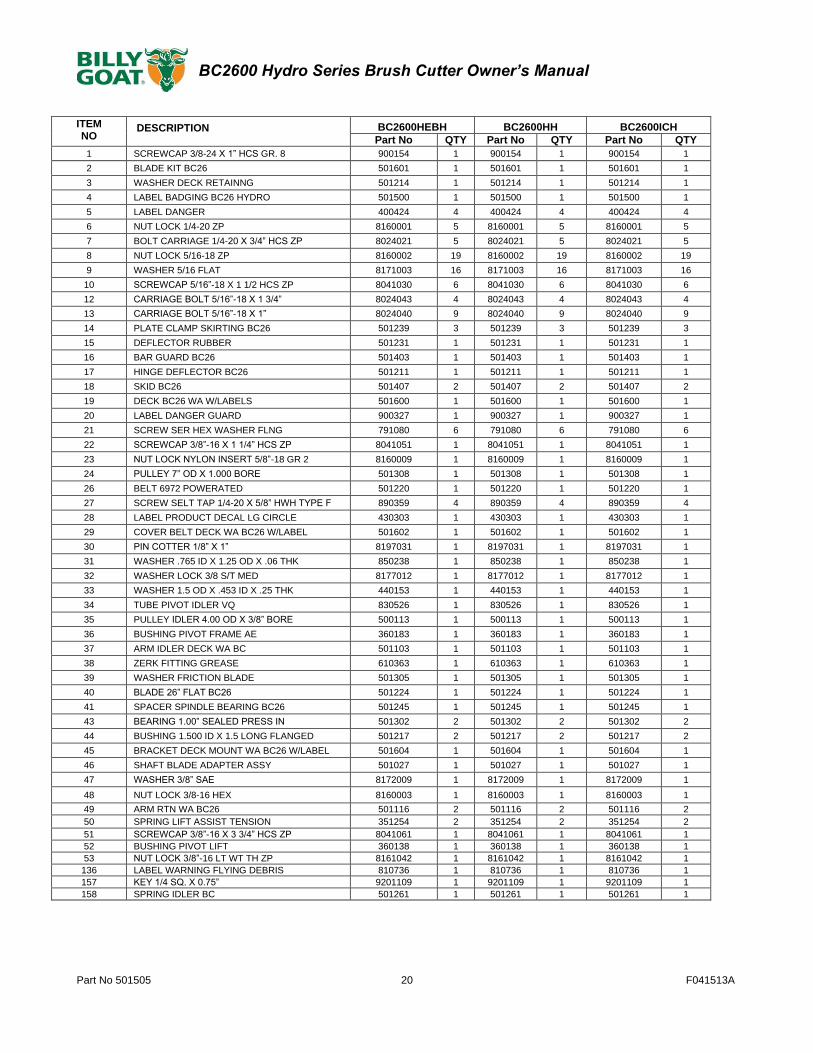
ITEM NO
DESCRIPTION BC2600HEBH BC2600HH BC2600ICH
Part No QTY Part No QTY Part No QTY
1 SCREWCAP 3/8-24 X 1” HCS GR. 8 900154 1 900154 1 900154 1
2 BLADE KIT BC26 501601 1 501601 1 501601 1
3 WASHER DECK RETAINNG 501214 1 501214 1 501214 1
4 LABEL BADGING BC26 HYDRO 501500 1 501500 1 501500 1
5 LABEL DANGER 400424 4 400424 4 400424 4
6 NUT LOCK 1/4-20 ZP 8160001 5 8160001 5 8160001 5
7 BOLT CARRIAGE 1/4-20 X 3/4” HCS ZP 8024021 5 8024021 5 8024021 5
8 NUT LOCK 5/16-18 ZP 8160002 19 8160002 19 8160002 19
9 WASHER 5/16 FLAT 8171003 16 8171003 16 8171003 16
10 SCREWCAP 5/16”-18 X 1 1/2 HCS ZP 8041030 6 8041030 6 8041030 6
12 CARRIAGE BOLT 5/16”-18 X 1 3/4” 8024043 4 8024043 4 8024043 4
13 CARRIAGE BOLT 5/16”-18 X 1” 8024040 9 8024040 9 8024040 9
14 PLATE CLAMP SKIRTING BC26 501239 3 501239 3 501239 3
15 DEFLECTOR RUBBER 501231 1 501231 1 501231 1
16 BAR GUARD BC26 501403 1 501403 1 501403 1
17 HINGE DEFLECTOR BC26 501211 1 501211 1 501211 1
18 SKID BC26 501407 2 501407 2 501407 2
19 DECK BC26 WA W/LABELS 501600 1 501600 1 501600 1
20 LABEL DANGER GUARD 900327 1 900327 1 900327 1
21 SCREW SER HEX WASHER FLNG 791080 6 791080 6 791080 6
22 SCREWCAP 3/8”-16 X 1 1/4” HCS ZP 8041051 1 8041051 1 8041051 1
23 NUT LOCK NYLON INSERT 5/8”-18 GR 2 8160009 1 8160009 1 8160009 1
24 PULLEY 7” OD X 1.000 BORE 501308 1 501308 1 501308 1
26 BELT 6972 POWERATED 501220 1 501220 1 501220 1
27 SCREW SELT TAP 1/4-20 X 5/8” HWH TYPE F 890359 4 890359 4 890359 4
28 LABEL PRODUCT DECAL LG CIRCLE 430303 1 430303 1 430303 1
29 COVER BELT DECK WA BC26 W/LABEL 501602 1 501602 1 501602 1
30 PIN COTTER 1/8” X 1” 8197031 1 8197031 1 8197031 1
31 WASHER .765 ID X 1.25 OD X .06 THK 850238 1 850238 1 850238 1
32 WASHER LOCK 3/8 S/T MED 8177012 1 8177012 1 8177012 1
33 WASHER 1.5 OD X .453 ID X .25 THK 440153 1 440153 1 440153 1
34 TUBE PIVOT IDLER VQ 830526 1 830526 1 830526 1
35 PULLEY IDLER 4.00 OD X 3/8” BORE 500113 1 500113 1 500113 1
36 BUSHING PIVOT FRAME AE 360183 1 360183 1 360183 1
37 ARM IDLER DECK WA BC 501103 1 501103 1 501103 1
38 ZERK FITTING GREASE 610363 1 610363 1 610363 1
39 WASHER FRICTION BLADE 501305 1 501305 1 501305 1
40 BLADE 26” FLAT BC26 501224 1 501224 1 501224 1
41 SPACER SPINDLE BEARING BC26 501245 1 501245 1 501245 1
43 BEARING 1.00” SEALED PRESS IN 501302 2 501302 2 501302 2
44 BUSHING 1.500 ID X 1.5 LONG FLANGED 501217 2 501217 2 501217 2
45 BRACKET DECK MOUNT WA BC26 W/LABEL 501604 1 501604 1 501604 1
46 SHAFT BLADE ADAPTER ASSY 501027 1 501027 1 501027 1
47 WASHER 3/8” SAE 8172009 1 8172009 1 8172009 1
48 NUT LOCK 3/8-16 HEX 8160003 1 8160003 1 8160003 1
49 ARM RTN WA BC26 501116 2 501116 2 501116 2
50 SPRING LIFT ASSIST TENSION 351254 2 351254 2 351254 2
51 SCREWCAP 3/8”-16 X 3 3/4” HCS ZP 8041061 1 8041061 1 8041061 1
52 BUSHING PIVOT LIFT 360138 1 360138 1 360138 1
53 NUT LOCK 3/8”-16 LT WT TH ZP 8161042 1 8161042 1 8161042 1
136 LABEL WARNING FLYING DEBRIS 810736 1 810736 1 810736 1
157 KEY 1/4 SQ. X 0.75” 9201109 1 9201109 1 9201109 1
158 SPRING IDLER BC 501261 1 501261 1 501261 1

Part No 501505 21 F041513A
BC2600 Hydro Series Brush Cutter Owner’s Manual
Engine Assembly

Part No 501505 22 F041513A
BC2600 Hydro Series Brush Cutter Owner’s Manual
ITEM NO
DESCRIPTION
BC2600HEBH BC2600HH BC2600ICH
Part No QTY Part No QTY Part No QTY
1 SCREWCAP 3/8-24 X 1” HCS GR. 8 900154 1 900154 1 900154 1
3 WASHER DECK RETAINING 501214 1 501214 1 501214 1
8 NUT LOCK 5/16”-18 ZP 8160002 2 8160002 2 8160002 2
11 ENGINE BASE WA W/LABELS 501603 1 501603 1 501603 1
27 SCREW SELT TAP 1/4-20 X 5/8” HWH TYPE F
890359 4 890359 4 890359 4
32 WASHER LOCK 3/8” S/T MED 8177012 1 8177012 1 8177012 1
54 CLUTCH 501223 1 501223 1 501223 1
55 WASHER LOCK S/T MED 8177013 1 8177013 1 8177013 1
56 SCREWCAP 7/16”-20 X 3 1/2” GR 8 W/PATCH
440150 1 440150 1 440150 1
58 ENGINE HONDA ELEC START 500333 1 - - - -
ENGINE BRIGGS - - - - 520046 1
ENGINE HONDA - - 500334 1 - -
59 SCREWCAP 5/16”-18 X 1 3/4 HCS ZP 8041031 2 8041031 2 8041031 2
60 WASHER 5/16” FLAT 8171003 4 8171003 4 8171003 4
61 LABEL WARNING FUEL 100261 1 100261 1 100261 1
62 LABEL SPARK ARRESTOR 100256 1 100256 1 100256 1
63 PLATE CHOKE BC26 500325 1 500325 1 - -
64 SCREWCAP 5/16-24 X 1” GR 8 ZP W/PATCH
400164 2 400164 2 400164 2
65 SCREWCAP 5/16”-18 X 2” HCS ZP 8041032 2 8041032 2 8041032 2
66 NUT FLANGE 5/16”-18 ZP 350346 4 350346 4 350346 4
67 SCREW SER HEX WSHR FLNG 5/16-18 X 3/4”
351264 4 351264 4 351264 4
68 GUARD REAR HYDRO BC26 501295 1 501295 1 501295 1
80 CABLE CLUTCH 501279 1 501279 1 501279 1
132 LABEL MADE IN USA 520116 1 520116 1 520116 1
133 LABEL READ MANUAL 890301 1 890301 1 890301 1
134 LABEL EAR EYE PROTECTION 890254 1 890254 1 890254 1
159 PIN CLEVIS 0.25 X 0.050 440124 1 440124 1 440124 1
160 PIN HITCH CLIP 0.051 X 3/4 440193 1 440193 1 440193 1

Part No 501505 23 F041513A
BC2600 Hydro Series Brush Cutter Owner’s Manual
Handle Assembly

Part No 501505 24 F041513A
BC2600 Series Brush Cutter Owner’s Manual
ITEM NO
DESCRIPTION BC2600HEBH BC2600HH BC2600ICH
Part No QTY Part No QTY Part No QTY 8 NUT LOCK 5/16-18 ZP 8160002 3 8160002 3 8160002 3
48 NUT LOCK 3/8-16 HEX 8160003 8 8160003 8 8160003 8
69 HANDLE LOWER LEFT 501400 1 501400 1 501400 1
70 BRACKET THROTTLE BC26 501251 2 501251 2 501251 2
72 SCREWCAP 3/8”-16 X 2” 8041054 4 8041054 4 8041054 4
73 WASHER 3/8” FLAT 8171004 16 8171004 16 8171004 16
74 BOLT SHOULDER 3/8”-16 X 1 1/2” 501313 1 501313 1 501313 1
75 SCREWCAP 3/8”-16 X 3” HCS ZP 8041058 4 8041058 4 8041058 4
76 WASHER 1/4” FLAT 8171002 2 8171002 2 8171002 2
77 BOLT CARRIAGE 5/16”-18 X 1 1/2” ZP 8024042 2 8024042 2 8024042 2
78 SCREWCAP 5/16”-18 X 1” ZP 8041028 2 8041028 2 8041028 2
79 WASHER LOCK 5/16” S/T MED 8177011 2 8177011 2 8177011 2
80 CABLE CLUTCH 501279 1 501279 1 501279 1
81 LEVER CONTROL BLADE 500312 1 500312 1 500312 1
82 CONTROL THROTTLE 440013 1 440013 1 440013 1
83 NUT LOCK LT #10-24 HEX 8164005 2 8164005 2 8164005 2
84 SCREW MACHINE FLAT HD PHIL #10-24 830514 2 830514 2 830514 2
85 LABEL DRIVE DIRECTION 501502 1 501502 1 501502 1
86 PLUG TUBE INSERT 1.25” OD 791056 4 791056 4 791056 4
87 GRIP HANDLE 500267 2 500267 2 500267 2
88 GUARD HAND BC26 501215 2 501215 2 501215 2
89 CONTROL MAGURA 351209 2 351209 2 351209 2
90 GRIP LEVER 0.125” X 1” X 5” RED 500379 1 500379 1 500379 1
91 HANDLE UPPER 501402 1 501402 1 501402 1
92 HANDLE LOWER RIGHT 501401 1 501401 1 501401 1
107 CABLE SPEED CONTROL RT 501276 1 501276 1 501276 1
130 CABLE SPEED CONTROL LFT 351271 1 351271 1 351271 1
135 LABEL BLADE ENGAGE 500177 1 500177 1 500177 1
137 LABEL THROTTLE 810656 1 - - - -
LABEL THROTTLE PULL START BC - - 501314 1 501314 1
138 CABLE THROTTLE 440178 1 440014 1 440014 1
141 BATTERY BRACKET REAR BC 500347 1 - - - -
142 BATTERY 12V W/LABEL 520200 1 - - - -
143 BOX THROTTLE CONTROL 501250 1 - - - -
144 SWITCH IGNITION 501286 1 - - - -
145 DELTA KEY REPLACEMENT 501286-S 1 - - - -
146 CABLE BATTERY BLACK 10” 790133 1
147 BUNGEE CORD BLACK 9” STRAP 79 790303 1 - - - -
148 CABLE BATTERY POSITIVE BC26 501222 1 - - - -
150 TUBE PIVOT IDLER VQ 830526 2 - - - -
151 BOLT CARRIAGE 5/16”-18 X 3/4” ZP 8024039 2 - - - -
152 SCREWCAP 1/4”-20 X 1” HCS ZP 8041006 2 - - - -
153 HARNESS WIRING BC26 501219 1 - - - -
154 WASHER 5/16” FLAT ZP 8171003 2 - - - -
155 NUT LOCK 5/16”-18 HEX ZP 8160002 2 - - - -
156 NUT LOCK 1/4”-20 HEX 8160001 2 - - - -

Part No 501505 25 F041513A
BC2600 Hydro Series Brush Cutter Owner’s Manual
Transaxle Drawing

Part No 501505 26 F041513A
BC2600 Series Brush Cutter Owner’s Manual
ITEM NO
DESCRIPTION BC2600HEBH BC2600HH BC2600ICH
Part No QTY Part No QTY Part No QTY 6 NUT LOCK 1/4”-20 HEX ZP 8160001 2 8160001 2 8160001 2
8 NUT LOCK 5/16”-18 8160002 10 8160002 10 8160002 10
11 ENGINE BASE WA W/LABELS 501603 1 501603 1 501603 1
27 SCREW SELT TAP 1/4-20 X 5/8” HWH TYPE F 890359 2 890359 2 890359 2
47 WASHER 3/8” SAE 8172009 1 8172009 1 8172009 1
48 NUT LOCK 3/8”-16 HEX 8160003 2 8160003 2 8160003 2
72 SCREWCAP 3/8”-16 X 2” HCS ZP 8041054 1 8041054 1 8041054 1
76 WASHER 1/4” SAE 8172007 1 8172007 1 8172007 1
78 SCREWCAP 5/16”-18 X 1” HCS ZP 8041028 1 8041028 1 8041028 1
79 WASHER LOCK 5/16” S/T MED 8177011 4 8177011 4 8177011 4
80 CABLE CLUTCH 501279 1 501279 1 501279 1
93 BRACKET IDLER ARM HYDRO BC26 501269 1 501269 1 501269 1
94 BOLT SHOULDER 1/2” X 2” 520031 1 520031 1 520031 1
95 BOLT CARRIAGE 5/16”-18 X 3/4” PLAIN 9024039 4 9024039 4 9024039 4
96 ARM IDLER DRIVE HYDRO BC26 WA 501112 1 501112 1 501112 1
97 PULLEY INSIDE IDLER BC26 501216 1 501216 1 501216 1
98 BRACKET SPRING IDLER 501297 1 501297 1 501297 1
99 BRACKET SPEED CONTROL BC26 501105 1 501105 1 501105 1
100 PLATE CAM SPEED CONTROL BC26 351110 1 351110 1 351110 1
101 BEARING 1/2” ID X 1.125” OD 351257 2 351257 2 351257 2
102 SPACER STEPPED SPEED CONTROL HYDRO DR 351255 2 351255 2 351255 2
103 SPACER EYELET SPEED CONTROL 351256 2 351256 2 351256 2
104 BUSHING 3/8” ID 1/2” OD X 3/8” LONG 840078 4 840078 4 840078 4
105 BUSHING PIVOT FRAME AE 360183 2 360183 2 360183 2
106 SCREWCAP 1/4-20 X 1 3/4 SKT BUT HD 840199 2 840199 2 840199 2
107 CABLE SPEED CONTROL RT 501276 1 501276 1 501276 1
108 WASHER 1/4” SAE 8172007 2 8172007 2 8172007 2
109 NUT LOCK 5/8”-11 LT WT TH ZP 8161046 1 8161046 1 8161046 1
110 BOLT SHOULDER 3/8” X 1 3/4” 351258 2 351258 2 351258 2
111 WASHER 5/8” FLAT 8172013 1 8172013 1 8172013 1
112 SPRING TENSION 800242 2 800242 2 800242 2
113 BELLCRANK SPEED CONTROL BC26 501114 2 501114 2 501114 2
114 ROD TRANS BYPASS BC26 501265 1 501265 1 501265 1
115 HAIR PIN COTTER 1/4” 900471 1 900471 1 900471 1
116 WASHER .765 ID X 1.25” OD X .06 850238 2 850238 2 850238 2
117 TRANSAXLE TUFF TORQ BC26 501218 1 501218 1 501218 1
118 BRACKET SUPPORT HYDRO TRANSAXLE 501267 1 501267 1 501267 1
119 TIRE 16” AG SP 501275 2 501275 2 501275 2
120 TRANS ROD ASSY 501025 1 501025 1 501025 1
121 BELT HYDRO TRANSAXLE BC26 501268 1 501268 1 501268 1
122 SCREW SELF TAP 5/16” X 3/4” HEX 8123128 1 8123128 1 8123128 1
123 SCREWCAP 5/16”-18 X 2 3/4” HCS ZP 8041035 4 8041035 4 8041035 4
124 WASHER 5/16” SAE 8172008 1 8172008 1 8172008 1
125 SCREWCAP 5/16”-18 X 3/4” HCS ZP 8041026 1 8041026 1 8041026 1
126 WASHER 3/4” SAE 8172015 6 8172015 6 8172015 6
127 RING RETAINING E 3/4” 850230 2 850230 2 850230 2
128 KEY 3/16” SQ X 2 1/8” 9201087 2 9201087 2 9201087 2
129 BRACKET BYPASS ROD 501272 1 501272 1 501272 1
130 CABLE SPEED CONTROL LFT 351271 1 351271 1 351271 1
139 LABEL DRIVE RELEASE 501504 1 501504 1 501504 1
140 LABEL CHOCK WHEELS 500168 2 500168 2 500168 2
158 SPRING IDLER BC 501261 1 501261 1 501261 1
161 SPRING PIN CONTROL ROD 501262 1 501262 1 501262 1
162 SPHERICAL ROD END MSF-5 351278 1 351278 1 351278 1
163 CONTROL ROD 501260 1 501260 1 501260 1
164 NUT JAM 5/16” NC 8143002 2 8143002 2 8143002 2
165 YOKE FEMALE STEEL 5/16” – 24 RH X 2.25” 501274 1 501274 1 501274 1