BH 24 - Wacker Neusonproducts.wackerneuson.com/manuals/Operators/0209743en_003.pdf · minimum...
30
Operator´s Manual Gasoline demolition hammer BH 24... 0209743en 003 04.2007
Transcript of BH 24 - Wacker Neusonproducts.wackerneuson.com/manuals/Operators/0209743en_003.pdf · minimum...
Operator´s Manual
Gasoline demolition hammer
BH 24...
0209743en 003
04.2007


T00940GB.fm 3
Important information
This machine has been provided with an EPA-certified engine.
Additional information can be found in the enginemanufacturer‘s notes.
Engine exhaust, some of its constitvents, and certain vehicle components contain or emit chemicals known to the State of
California to cause cancer and birth defects or other reproduc-tive harm.
WARNING
Caution
This engine is an EPA engine.Adjusting the engine speed will interfere with EPA certification and
the emissions.
Only authorized personnel can make adjustments to this engine.Please contact you nearest engine dealer or your Wacker Dealer for more
information.

T00953GB.fm 4
Emission Control System Information
Source of EmissionsThe combustion process produces carbon monoxide, oxides ofnitrogen, and hydrocarbons. Control of hydrocarbons and oxides ofnitrogen is very important because, under certain conditions, theyreact to form photochemical smog when subjected to sunlight. Carbonmonoxide does not react in the same way, but it is toxic.
Wacker utilizes lean carburetor settings and other systems to reducethe emissions of carbon monoxide, oxides of nitrogen, andhydrocarbons.
The U.S. and California Clean Air ActsEPA and California regulations require all manufacturers to furnishwritten instructions describing the operation and maintenance ofemission control systems.
The following instructions and procedures must be followed in order tokeep the emissions from your Wacker engine within the emissionsstandards.
Tampering and AlteringTampering with or altering the emission control system may increaseemissions beyond the legal limit. Among those acts that constitutetampering are:
•Removal or alteration of any part of the intake, fuel, or exhaustsystems.
•Altering or defeating the speed-adjusting mechanism to cause theengine to operate outside its design parameters.
Problems That May Affect EmissionsIf you are aware of any of the following symptoms, have your engineinspected and repaired by your servicing dealer.
•Hard starting or stalling after starting.
•Rough idle.
•Misfiring or backfiring under load.
•Afterburning (backfiring).
•Black exhaust smoke or high fuel consumption.

T00953GB.fm 5
Replacement Parts
The emission control systems on your Wacker engine were designed,built, and certified to conform with EPA and California emissionsregulations. We recommend the use of genuine Wacker partswhenever you have maintenance done. These original-designreplacement parts are manufactured to the same standards as theoriginal parts, so you can be confident of their performance. The useof replacement parts that are not of the original design and quality mayimpair the effectiveness of your emission control system.
A manufacturer of an aftermarket part assumes the responsibility thatthe part will not adversely affect emission performance. Themanufacturer or rebuilder of the part must certify that use of the partwill not result in a failure of the engine to comply with emissionregulations.
Maintenance
Follow the maintenance schedule. Remember that this schedule isbased on the assumption that your machine will be used for itsdesigned purpose. Sustained high-load or high-temperature operation,or use in unusually wet or dusty conditions, will require more frequentservice.
OXYGENATED FUELS
Some conventional gasolines are being blended with alcohol or anether compound. These gasolines are collectively referred to asoxygenated fuels. To meet clean air standards, some areas of theUnited States and Canada use oxygenated fuels to help reduceemissions.
If you use an oxygenated fuel, be sure it is unleaded and meets theminimum octane rating requirement.
Before using an oxygenated fuel, try to confirm the fuel’s contents.Some States / Provinces require this information to be posted on thepump.
The following are EPA-approved percentages of oxygenates:
ETHANOL - (ethyl or grain alcohol) 10% by volume. You may usegasoline containing up to 10% ethanol by volume. Gasoline containingethanol may be marketed under the name “Gasohol”.
MTBE - (methyl tertiary butyl ether) 15% by volume. You may usegasoline containing up to 15% MTBE by volume.

T00953GB.fm 6
METHANOL - (methyl or wood alcohol) 5% by volume. You may usegasoline containing up to 5% methanol by volume, as long as itcontains cosolvents and corrosion inhibitors to protect the fuel system.Gasoline containing more than 5% methanol by volume may causestarting and/or performance problems. It may also damage metal,rubber, and plastic parts of your fuel system.
If you notice any undesirable operating symptoms, try another servicestation, or switch to another brand of gasoline.
Fuel system damage or performance problems resulting from the useof an oxygenated fuel containing more than the percentages ofoxygenates mentioned above are not covered under warranty.
Emission Control System Warranty
Your new Wacker engine complies with the U.S. EPA emissionsregulations. Wacker provides the same emission warranty coveragefor engines sold in all 50 states.
YOUR WARRANTY RIGHTS AND OBLIGATIONS
All States
Wacker must warrant the emission control system on your engine forthe period of time listed below provided there has been no abuse,neglect or improper maintenance of your engine. Where a warrantablecondition exists, Wacker will repair your engine at no cost to youincluding diagnosis, parts and labor.
Your emission control system may include such parts as thecarburetor, the ignition system and the catalytic converter.
Also included may be hoses, connectors and other emission-relatedassemblies.
MANUFACTURER’S WARRANTY COVERAGE:
The 1998 and later engines are warranted for two years. If anyemission-related part on your engine is defective, the part will berepaired or replaced by Wacker.

T00953GB.fm 7
OWNER’S WARRANTY RESPONSIBILITY:
As the engine owner, you are responsible for the performance of therequired maintenance listed in your owner’s manual. Wackerrecommends that you retain all receipts covering maintenance on yourengine, but Wacker cannot deny warranty coverage solely for the lackof receipts or for your failure to ensure the performance of allscheduled maintenance.
As the engine owner, you should be aware that Wacker may deny youwarranty coverage if your engine or a part has failed due to abuse,neglect, improper maintenance or unapproved modifications.
You are responsible for presenting your engine to a Wacker dealer assoon as a problem exists. The warranty repairs should be completedin a reasonable amount of time, not to exceed 30 days.
If you have any questions regarding your warranty rights andresponsibilities, you should contact your local Wacker dealer.
WARRANTY COVERAGE:
Wacker engines sold after January 1, 1998, are covered by thisEmission Control System Warranty for a period of two years from thedate of delivery to the original retail purchaser. This warranty istransferable to each subsequent purchaser for the duration of thewarranty period.
Warranty repairs will be made without charge for diagnosis, parts orlabor. All defective parts replaced under this warranty become propertyof Wacker. A list of warranted parts is located on the next page. Normalmaintenance items, such as spark plugs and filters, that are on thewarranted parts list are warranted up to the required replacementinterval only.
Wacker is also liable for damages to other engine components causedby a failure of any warranted parts during the warranty period.
Only Wacker approved replacement parts may be used in theperformance of any warranty repairs and must be provided withoutcharge to the owner. The use of replacement parts not equivalent tothe original parts may impair the effectiveness of your engine emissioncontrol system. If such a replacement part is used in the repair ormaintenance of your engine, and an authorized Wacker dealerdetermines it is defective or causes a failure of a warranted part, yourclaim for repair of your engine may be denied. If the part in question isnot related to the reason your engine requires repair, your claim will notbe denied.

T00953GB.fm 8
TO OBTAIN WARRANTY SERVICE:
You must take your Wacker product along with proof of originalpurchase date, at your expense, to any Wacker authorized dealerduring their normal business hours. Claims for repair or adjustmentfound to be caused solely by defects in material or workmanship willnot be denied because the engine was not properly maintained andused.
EXCLUSIONS:
FAILURES OTHER THAN THOSE RESULTING FROM DEFECTS INMATERIAL OR WORKMANSHIP ARE NOT COVERED BY THISWARRANTY. THIS WARRANTY DOES NOT EXTEND TOEMISSION CONTROL SYSTEMS OR PARTS WHICH AREAFFECTED OR DAMAGED BY OWNER ABUSE, NEGLECT,IMPROPER MAINTENANCE, MISUSE, MISFUELING, IMPROPERSTORAGE, ACCIDENT AND/OR COLLISION, THEINCORPORATION OF, OR ANY USE OF, ANY ADD-ON ORMODIFIED PARTS, UNSUITABLE ATTACHMENTS, OR THEUNAUTHORIZED ALTERATION OF ANY PART.
THIS WARRANTY DOES NOT COVER REPLACEMENT OFEXPENDABLE MAINTENANCE ITEMS MADE IN CONNECTIONWITH REQUIRED MAINTENANCE SERVICES AFTER THE ITEM’SFIRST SCHEDULED REPLACEMENT AS LISTED IN THEMAINTENANCE SECTION OF THE PRODUCT OWNER’S MANUAL,SUCH AS SPARK PLUGS AND FILTERS.
DISCLAIMER OF CONSEQUENTIAL DAMAGE AND LIMITATIONSOF IMPLIED WARRANTIES:
WACKER DISCLAIMS ANY RESPONSIBILITY FOR INCIDENTALOR CONSEQUENTIAL DAMAGES SUCH AS LOSS OF TIME ORTHE USE OF THE POWER EQUIPMENT, OR ANY COMMERCIALLOSS DUE TO THE FAILURE OF THE EQUIPMENT; AND ANYIMPLIED WARRANTIES ARE LIMITED TO THE DURATION OF THISWRITTEN WARRANTY. THIS WARRANTY IS APPLICABLE ONLYWHERE THE U.S. EPA EMISSION CONTROL SYSTEMWARRANTY REGULATION IS IN EFFECT.

T00953GB.fm 9
SYSTEMS COVERED BY THIS WARRANTY
PARTSDESCRIPTIONS
FUEL METERING CARBURETOR ASSEMBLY
EXHAUST SYSTEM MUFFLER
AIR INDUCTION AIR FILTER HOUSINGAIR FILTER ELEMENT*
IGNITION FLYWHEEL MAGNETOIGNITION MODULESPARK PLUG CAPSPARK PLUG*
MISCELLANEOUS PARTS
TUBING, FITTINGS, SEALS, GASKETSAND CLAMPS ASSOCIATED WITH THESE LISTED ITEMS
* Indicates expendable maintenance items.

T00953GB.fm 10

Vorwort.fm 11
Foreword1. Foreword
For your own safety and protection from bodily injuries, carefully read,understand and follow the safety instructions in this manual.
Please operate and maintain your Wacker machine in accordance withthe instructions in this manual. Your Wacker machine will reward yourattention by giving trouble-free operation and a high degree ofavailability.
Replace faulty or defective components Immediately.
All rights, especially the right for copying and distribution are reserved
Copyright 2007 by Wacker Construction Equipment AG
No part of this publication may be reproduced in any form or by anymeans, electronic or mechanical, including photocopying, withoutexpress permission in writing from Wacker Construction Equipment AG.
Any type or manner of reproduction, distribution or storage on datacarriers or storage mediums not authorized by Wacker represents aninfringement of valid copyrights and will be prosecuted. We expresslyreserve the right to make technical modifications - even without duenotice - which aim at improving our machines or increasing their safetystandards.

Table of contents
12
1. Foreword 11
2. Safety instructions 13
2.1 General ................................................................................................132.2 Operation .............................................................................................132.3 Safety checks ......................................................................................152.4 Maintenance ........................................................................................162.5 Transport .............................................................................................162.6 Maintenance checks ............................................................................16
3. Technical Data 17
4. Description 18
4.1 Applications .........................................................................................184.2 Transport to worksite ...........................................................................184.3 Functional description .........................................................................18
5. Operation 19
5.1 Starting up ...........................................................................................195.2 Engine .................................................................................................195.3 During operation ..................................................................................205.4 After operation .....................................................................................205.5 Tip for working correctly ......................................................................20
6. Maintenance 21
6.1 Maintenance schedule ........................................................................216.2 Engine .................................................................................................226.3 Percussion system, crankcase ............................................................22
7. Malfunction 23
7.1 Troubleshooting ...................................................................................23
8. Signs 24
EC Declaration of Conformity 25
DIN EN ISO 9001 Certificate 27

SV00044GB.fm 13
Safety instructions2. Safety instructions
for the use of drilling and breaking hammers with combustionengines
2.1 General
2.1.1 Drilling and breaking hammers may only be operated by persons who∗ are at least 18 years of age,∗ are physically and mentally fit for this job,∗ have been instructed in operating drilling and breaking hammers and
proven their ability for the job to the employer∗ may be expected to carry out the job they are charged with carefully.
The persons must be assigned the job of operating drilling andbreaking hammers by the employer.
2.1.2 Drilling and breaking hammers are to be applied for their proper use.
Both the manufacturer’s operating instructions and these safetyinstructions have to be observed.
2.1.3 The persons charged with the operation of these hammers have to be
made familiar with the necessary safety measures relating to themachine. In case of extraordinary uses, the employer shall give thenecessary additional instructions.
2.1.4 This machine generates noise that exceeds the country-specific
permissible noise levels (individual rating level). It may therefore benecessary to wear ear protection. WACKER recommends that you always wear ear protection.
2.2 Operation
2.2.1 The function of operation levers or elements is not to be influenced orrendered ineffective.
2.2.2 Before going on breaks, the operator has to switch of the engine and
has to place the drilling and breaking hammer in such a manner that itcannot turn over.

Safety instructions
SV00044GB.fm 14
2.2.3 Wear safety goggles in order to avoid injuries to the eyes.
2.2.4 We recommend wearing suitable working gloves.
2.2.5 Wear safety shoes while working with drilling and breaking hammers.
2.2.6 Drilling and breaking hammers are always to be operated with bothhands on the handles provided for this purpose.
2.2.7 When working with drilling and breaking hammers, especially when
carrying out drilling jobs, the operator has to have a firm stand,particularly when working on scaffolding and ladders.
2.2.8 Drilling and breaking hammers are to be guided such that hand injuries
caused by solid objects are avoided. When carrying out demolitionjobs at elevated places, special care is required to prevent the machineor the operator from falling.
2.2.9 Avoid body contact with earthed components. When breaking
connecting passages, make sure that there are no electric wires or gaspipes. No one may stay in the room to which the passage is brokenthrough, as there is danger of injuries because of falling stones ortools.
2.2.10 During operation the tool holder must be closed. Tools and tool holder
must be checked for wear in order to guarantee proper functioning ofholder.
2.2.11 The operation of this machine may cause broken - off pieces to be
flung away. Therefore, during operation, no one except the operator isto come near this machine.
2.2.12 Switch off the engine of drilling and breaking hammers before
changing tools.
2.2.13 The tools always have to be in perfect conditions.
2.2.14 Do not smoke or handle open fire near this machine.

SV00044GB.fm 15
Safety instructions2.2.15 The tank lid must fit tightly. Shut fuel cock if available when stopping
the engine. For long distance transports of machines operated by fuelof fuel-mixtures, the fuel tank has to be drained competely.Leaky fuel tanks may cause explosions and must therefore bereplaced immediately.
2.2.16 Stop engine before filling fuel tank. When refilling fuel tank, do not
allow fuel to come into contact with the hot parts of the engine or spillonto the ground.
2.2.17 Make sure that sufficient fresh air is available when operating drilling
and breaking hammers with combustion engines in enclosed areas,tunnels, adits, or deep trenches. For this particular use we offerelectrically driven drilling and breaking hammers.
2.2.18 Do not operate this machine in areas where explosions may occur.
2.3 Safety checks
2.3.1 Drilling and breaking hammers may only be operated with all safetydevices installed.
2.3.2 Before starting operation, the operator has to check that all control and
safety devices function properly.
2.3.3 Before starting operation, the overload clutch of drilling hammers hasto be checked for proper functioning.
2.3.4 In case of defects of the safety devices or other defects reducing the
operational safety of the drilling and breaking hammers, the supervisorhas to be informed immediately.
2.3.5 The machine must to be switched off immediately in case of defects
jeopardizing the operational safety of the equipment.

Safety instructions
SV00044GB.fm 16
2.4 Maintenance
2.4.1 Only use original spare parts. Modifications to this machine, includingthe adjustment of the maximum engine speed set by the manufacturer,are subject to the express approval of WACKER. In case ofnonobservance all liabilities shall be refused.
2.4.2 Stop engine and pull off spark plug cap (if available) before carrying
out maintenance jobs, to avoid unintentional starting of the machine.Deviations from this are only allowed if the maintenance job requires arunning engine.
2.4.3 Take care when checking the ignition system.
The electronic ignition system produces a very high voltage.
2.4.4 All safety devices must be reinstalled properly immediately after
maintenance and repair jobs have been completed.
2.5 Transport
2.5.1 When being transported on vehicles, precautions have to be taken thatthese hammers do not slip or turn over.
2.6 Maintenance checks
2.6.1 According to the conditions and frequency of use, drilling and breakinghammers have to be checked for safe operation at least once a yearby skilled technicians, such as those found at WACKER-servicedepots and have to be repaired if necessary.
Please also observe the corresponding rules and regulations valid in yourcountry.
Technical Data
TD00738GB.fm 17
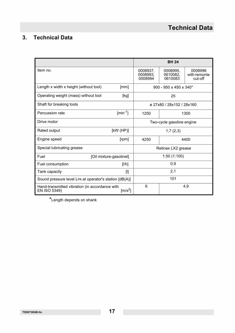
3. Technical Data
*Length depends on shank
BH 24
Item no. 0008937, 0008993, 0008994
0008995, 0610082, 0610083
0008996with remonte
cut-off
Length x width x height (without tool) [mm] 900 - 950 x 450 x 340*
Operating weight (mass) without tool [kg] 25
Shaft for breaking tools ø 27x80 / 28x152 / 28x160
Percussion rate [min-1] 1250 1300
Drive motor Two-cycle gasoline engine
Rated output [kW (HP)] 1,7 (2,3)
Engine speed [rpm] 4250 4400
Special lubricating grease Retinax LX2 grease
Fuel [Oil mixture-gasolinel] 1:50 (1:100)
Fuel consumption [l/h] 0,9
Tank capacity [l] 2,1
Sound pressure level LPA at operator's station [dB(A)] 101
Hand-transmitted vibration (in accordance with EN ISO 5349) [m/s2]
6 4,9

Description
T01112GB.fm 18
4. Description
4.1 Applications
When breaking up concrete and asphalt or soil that is full of boulders,for breaking off in concrete, brickwork and other building materials(overgrown or frozen ground) etc., for tearing up streets and concrete,asphalt, tar, wood and pavement, for paring clay, loam, peat and salts,for crushing soil that has been pressed by vehicles, for ramming inposts and grounding rods with the respective tools. In track laying topack ballast under railway sleepers.
4.2 Transport to worksite
Requirements:
∗ When transporting the Wacker machine, use only suitable hoistinggear with a minimum load-bearing capacity of 30 kg.
∗ Always turn off the motor during transportation!∗ When transporting on the cargo area of a vehicle, fasten the Wacker
machine.
Note: Also observe the regulations in the chapter Safety information!
4.3 Functional description
The drive motor drives the percussion system via gears andconnecting system. The torque is transferred non-positively by thecentrifugal clutch.The drive motor works according to the two-cycle principle and isstarted mechanically via a recoil starter.
Machines with remote cut-off:The machine is equipped for the connection of a remote cut-off. Forfurther information on the remote cut-off, refer to the manufacturer'soperator's manual.To operate machines without remote cut-off, the shorting plug must beplugged into the connector.

Operation
T01112GB.fm 19
5. Operation
5.1 Starting up5.1.1 Inserting the tool
∗ Swivel out the handle (9) on the tool holder (11).∗ Clean shank (10) and grease slightly.∗ Clean the tool shank (10) and lubricate it a little.∗ Press the handle (9) on the tool holder (11).
Only use sharp tools!Faulty shanks may damage the percussion system.
5.2 EngineFuel
Standard: Two-cycle mixture of oil/fuel at a ratio of 1:50 or,alternatively, 1:100.Use two-cycle motor oil of the specification NMMA TC-W3, API TC,JASO FC or ISO EGD. Lead-free fuel can also be used!
Starting the engine
∗ Open the fuel tap.∗ Cold start: Close the choke.∗ Warm start: Open the choke.
Note: The engine is hand warm or hotter with warm start.∗ Press the gas handle all the way through and hold it (full throttle
position).∗ Pull out the starter rope until compression resistance can be felt and
hen let it roll back in again.∗ Pull the starter rope with force, but not suddenly.∗ As soon as you hear the engine start, open the choke to prevent that
too much fuel enters the carburetor.∗ Pull the starter rope again with force.∗ The engine starts.
Note: If the engine does not start after another two attempts, close thechoke again and repeat the procedure.
∗ Let starter rope slowly roll back in.∗ Open the choke while the engine is warming up.
Operation
T01112GB.fm 20
Note the following with regard to winter operation:
The cold grease in the percussion system may increase the resistanceto such an extent that the centrifugal clutch slips. In this case, allow themachine to warm up at low engine speed (do not press the gas handle)to prevent the centrifugal clutch from premature wear.
5.3 During operation
Keep breaker dry and clean. Avoid no-load strokes. Never allow thehammer to run with throttle wide open when forcing away broken or cutoff material or when lifting the hammer. When lifting the hammer, theengine is decelerated by releasing the gas lever in the handle.
5.4 After operation
5.4.1 Brief interruption from workPress short-circuit button.
5.4.2 Finishing the workClose the fuel tap. Let the motor continue to run until the fuel in thecarburetor is used up..
5.4.3 Long break in operationClean the hammer. Add anticorrosive oil to the fuel mixture and let themotor run for 5 minutes. Oil the places that are prone to rust.
5.5 Tip for working correctly
5.5.1 Apply the gasoline demolition hammer with the tool to the material tobe worked on and press the handle down until the hood locksnoticeably into place. Then start operation by pressing the throttlelever.
5.5.2 Pressing forcefully against the surface you are working on does notimprove the tool's performance. The pressure force should besufficient to lock the hood into place, but there should be no contactwith the upper and lower stopmounts. Otherwise there will be anincrease inhand-transmitted vibrations.
5.5.3 Hold the chisel against the material you are working on so that thematerial can be chipped off. This prevents the chisel from jamming andthe breaking output is increased.

Maintenance
T01113GB.fm 21
6. Maintenance
6.1 Maintenance schedule
Component Maintenance work Maintenance interval
Air filter Check for external damage and tight fit.
Daily
Fuel Check the tank seal for leakage - change, if necessary.
Miscellaneous Check that Bowden cable moves freely.
Tools Check the shanks and cutting edges - if necessary, sharpen, reforge or replace
Air filter Check filter element - clean or replace, if necessary.Weekly
Cylinder Cooling ribs dirt-free - dry clean if necessary.
Ignition Clean the spark plug, check the spark plug air gap is 0.5 mm. Monthly
MiscellaneousCheck the tool holder for wear - change, if necessary.
Regrease via grease nipples. 20 hours
Fuel tank Clean.
AnnuallyFuel filter Change.
Fuel line in thetank
Check for porosity and damage - change if necessary
Maintenance
T01113GB.fm 22
6.2 Engine
6.2.1 Air filter: Clean by knocking or blowing (from inside to the outside), donot use gasoline or similar cleaning agent! Replace filters that are verydirty or that have been used often. Check the filter holder beforeinserting.
6.2.2 Fuel supply and carburetor: Clean the components regularly. Blowthrough the jets.
6.2.3 Spark plug: Clean sooted or wet spark plugs. Check the spark plug airgap (0.5 mm).
6.2.4 Ignition: Gap between the fan wheel and ignition armature 0.3 - 0.4 mm.
6.2.5 Cylinder: Keep the cooling ribs clean.6.2.6 Starter: Lightly lubricate the bolts after approx. 200 hours in operation.
6.3 Percussion system, crankcase
Lubricante (see technicla data)
Lubrication check
6.3.1 After 20 hours of operation, the hammer must be lubricated via thelubrication nipple provided with a red mark which is positioned on thecrankcase.

Malfunction
T01121GB.fm 23
7. Malfunction
7.1 Troubleshooting
Malfunction for machines with remote cut-off:
Malfunction Cause Remedy
Engine will not start.
Shorting plug for remote cut-off not occupied.
Connect remote cut-off.
Insert shorting plug.
Remote cut-off is not functioning properly
Check remote cut-off according to the manufacturer's instructions
Signs
SK00642GB.fm 24
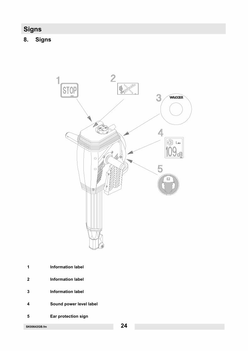
8. Signs
1 Information label
2 Information label
3 Information label
4 Sound power level label
5 Ear protection sign
C0031004GB.fmFile
cer
tific
ate
care
fully
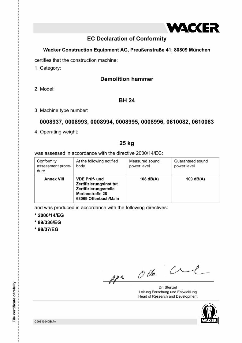
EC Declaration of Conformity
Wacker Construction Equipment AG, Preußenstraße 41, 80809 München
certifies that the construction machine:1. Category:
Demolition hammer2. Model:
BH 243. Machine type number:
0008937, 0008993, 0008994, 0008995, 0008996, 0610082, 06100834. Operating weight:
25 kgwas assessed in accordance with the directive 2000/14/EC:
and was produced in accordance with the following directives:* 2000/14/EG* 89/336/EG* 98/37/EG
Conformity assessment proce-dure
At the following notified body
Measured sound power level
Guaranteed sound power level
Annex VIII VDE Prüf- und ZertifizierungsinstitutZertifizierungsstelleMerianstraße 2863069 Offenbach/Main
108 dB(A) 109 dB(A)
Dr. StenzelLeitung Forschung und EntwicklungHead of Research and Development

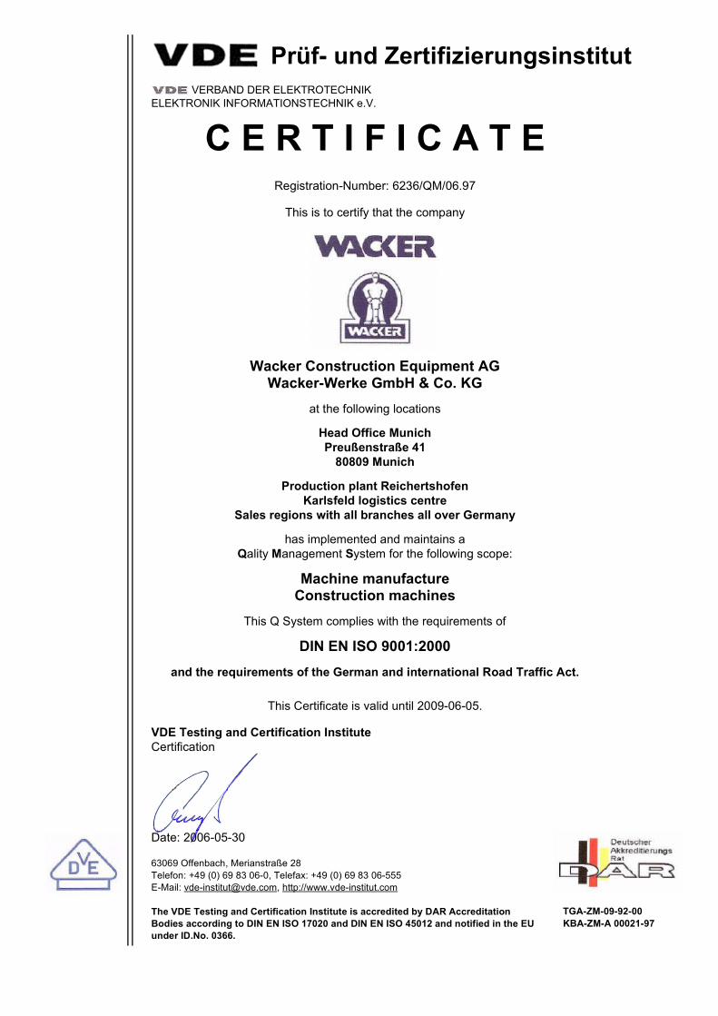
Prüf- und Zertifizierungsinstitut VERBAND DER ELEKTROTECHNIK
ELEKTRONIK INFORMATIONSTECHNIK e.V.
C E R T I F I C A T ERegistration-Number: 6236/QM/06.97
This is to certify that the company
Wacker Construction Equipment AGWacker-Werke GmbH & Co. KG
at the following locations
Head Office MunichPreußenstraße 41
80809 Munich
Production plant ReichertshofenKarlsfeld logistics centre
Sales regions with all branches all over Germany
has implemented and maintains a Qality Management System for the following scope:
Machine manufactureConstruction machines
This Q System complies with the requirements of
DIN EN ISO 9001:2000and the requirements of the German and international Road Traffic Act.
This Certificate is valid until 2009-06-05.
VDE Testing and Certification InstituteCertification
Date: 2006-05-30
63069 Offenbach, Merianstraße 28Telefon: +49 (0) 69 83 06-0, Telefax: +49 (0) 69 83 06-555E-Mail: [email protected], http://www.vde-institut.com
The VDE Testing and Certification Institute is accredited by DAR AccreditationBodies according to DIN EN ISO 17020 and DIN EN ISO 45012 and notified in the EUunder ID.No. 0366.
TGA-ZM-09-92-00KBA-ZM-A 00021-97
DIN EN ISO 9001 Certificate

Wacker Construction Equipment AG - Preußenstraße 41 - 80809 München - Tel.: +49-(0)89-3 54 02-0 - Fax: +49-(0)89-3 54 02-390Wacker Corporation - P.O. Box 9007 - Menomonee Falls, WI 53052-9007 - Tel.: +1-(1)(262)-255-0500 - Fax: +1-(1)(262)-255-0550 - Tel.: (800)770-0957Wacker Asia Pacific Operations-Skyline Tower, Suite 2303, 23/F, 39 Wang Kwong Road, Kowloon Bay, Hong Kong-Tel.: +852 2406 6032-Fax: +852 2406 6021