Bentley substation civil instruction manual-v2.3
88
Bentley Substation Civil Design Instruction Manual Page 1 1/31/2013 Bentley Substation Instruction Manual v2.3 Civil Design Guide
-
Upload
gilberto-mejia -
Category
Engineering
-
view
152 -
download
9
Transcript of Bentley substation civil instruction manual-v2.3

Bentley Substation Civil Design Instruction Manual
Page 1 1/31/2013
Bentley Substation
Instruction Manual v2.3
Civil Design Guide
Bentley Substation Civil Design Instruction Manual
Page 2 1/31/2013
Table of Contents
Preface ................................................................................................................................................... 6
A. Purpose: ......................................................................................................................................... 6
B. Requirements: ................................................................................................................................ 6
C. Legends: .......................................................................................................................................... 6
E. Glossary, Definition, and Terminology: .......................................................................................... 6
I. General Approach ............................................................................................................................. 8
A. Software Overview ........................................................................................................................ 8
B. Drawing Size, Page Format, Title Block, and Scaling ..................................................................... 8
C. Handling Existing Vector/Raster Drawings .................................................................................... 8
II. Design Approach .............................................................................................................................. 9
III. Launching Bentley Substation and Working with Project Manager ........................................... 10
A. Restoring a Project from Backup ................................................................................................. 11
B. Creating a New Project ................................................................................................................ 13
C. Creating a New Drawing Page ..................................................................................................... 14
D. Copying a project ....................................................................................................................... 17
E. Copying a Drawing Page ............................................................................................................. 18
F. Rename a Project or Drawing Page ............................................................................................ 19
G. Modify a Project or Drawing Page .............................................................................................. 21
H. Running Reports ......................................................................................................................... 22
IV. Designing with Existing Vector/Raster Drawings .......................................................................... 22
A. General Method ......................................................................................................................... 22
B. Bringing in Existing Vector Files to a Bentley Substation Drawing ............................................. 23
C. Placing Symbols into Vector/Raster Graphics ............................................................................. 26
V. Section NOT used in Civil Manual ................................................................................................... 26
Bentley Substation Civil Design Instruction Manual
Page 3 1/31/2013
VI. Designing the Civil Master Site Layout .......................................................................................... 26
A. Creating a New Civil 3D Layout Page .......................................................................................... 28
B. Creating a 3D Civil Master Site Layout using Elements from a 3D Topographical drawing ........ 29
C. Creating a 3D Master Site Layout from an Existing Grading Plan ............................................... 29
D. Creating the DTM ......................................................................................................................... 30
E. Additional Features that need to be added to the 3D Civil Master Site Layout File. ................... 31
F. Accuracy Check ............................................................................................................................. 34
G. Level Locking ................................................................................................................................ 34
VII. Inserting 3D Objects ..................................................................................................................... 36
A. Insert Substation Object in the Civil Master Site Layout ............................................................ 36
B. Inserting Single Objects .............................................................................................................. 38
C. Inserting Variable Objects .......................................................................................................... 40
D. Inserting Repeating Objects ....................................................................................................... 40
E. Assigning Balloon Numbers to Foundations. ................................................................................ 40
F. Assigning Job Numbers to Foundations. ...................................................................................... 42
VIII. Design Construction Drawings ..................................................................................................... 44
A. Creating a Construction Drawing(s) from the Civil Master Site Layout ....................................... 44
B. Creating Standard 2D Drawings (i.e., Structure and Foundation Drawings) ............................... 51
C. Annotating Drawings ................................................................................................................... 55
D. Dimensioning Drawings............................................................................................................... 55
E. Creating Section Callouts ............................................................................................................. 55
IX. Foundations Data Sheet Report ..................................................................................................... 55
A. Running Foundation Data Sheet Report ..................................................................................... 55
B. Embedding Excel Report into Foundation Data Sheet Drawing .................................................. 58
C. Modifying, Moving, Resizing or Deleting Embedded Excel Report ............................................. 60
Bentley Substation Civil Design Instruction Manual
Page 4 1/31/2013
X. Generating Drawing List .................................................................................................................. 61
XI. Plotting Construction Drawing(s) ................................................................................................... 61
A. Printing Full Size Drawings for Final Issue ................................................................................... 61
B. Printing Drawings for Review (not full size) ................................................................................. 67
C. Publishing a Project in PDF with Links maintained ..................................................................... 68
D. Creating 3D PDFs ........................................................................................................................ 69
XII. Backing up and archiving a Project ............................................................................................... 70
A. Overview ..................................................................................................................................... 70
B. Interim Mandatory Backup for Data Retention .......................................................................... 71
C. Archiving a Project upon Completion ........................................................................................... 72
Appendix A. Quick Guide ..................................................................................................................... 73
Appendix B. Basic Bentley Substations Drafting Overview ................................................................ 74
1. Accudraw “o” and “enter” commands ......................................................................................... 74
2. DGN files, design models, and sheet model ................................................................................. 75
3. Levels ............................................................................................................................................ 76
4. Reference Command .................................................................................................................... 79
5. Merge to Master Command ......................................................................................................... 81
Appendix C: Creating Details ............................................................................................................... 83
Appendix D: Retaining Legacy Title Blocks and 0, 1, and 2 Drawings ................................................ 88

Bentley Substation Civil Design Instruction Manual
Page 5 1/31/2013
Date Rev. Description By Chk by
2.0 Will be Updated Later JOSB
01/31/13 2.3 Updated and revised to be consistent with Electrical V2.3 LD

Bentley Substation Civil Design Instruction Manual
Page 6 1/31/2013
Preface
A. Purpose:
This document outlines all necessary steps and procedures for Civil related work required to
complete a substation design project utilizing Bentley Substation software within PG&E
configured environment. All users need to follow these steps to ensure contents can be properly
utilized among PG&E and contractors.
B. Requirements:
1. Bentley Substation should be properly Installed and Configured.
2. Master PG&E Parts Database has been installed.
3. Master catalogs (2D/3D) are present.
C. Legends:
1. Text in single quote is: ‘Running a command’.
2. Text in double quote is: “Column or field name existing in the software”.
3. Text in bold is: USER TO KEY-IN VALUE(S).
4. Text in Italic and bold is: Hint or CAUTION or PAY CLOSE ATTENTION.
E. Glossary, Definition, and Terminology:
Backup: The process, which bundles all related files/data of a project to one single file (*.prj)
Construction Drawing: Drawings to be issued out to construction or vendor drawing. These
drawings contain the Title Block and where annotation, dimensioning and clouding occurs.
Design Model: A 2D or 3D workspace model within Bentley Substation. These model(s) are
referenced into the Construction Mode Drawing. The 2D and 3D design models are
available with x & y and x, y, & z coordinates respectively. Typically text or annotations are
not placed within design models and items are drawn at 1:1 scale. This model has no Title
Block.
Drawing Set: Typically all drawings for a specific project will be assigned to the same
drawing set (i.e., Civil). Note that Electricals will populate this field differently.
DTM: Digital Terrain Model
font001: Font style to be used in PG&E Bentley Substation environment for Civil drawings
(Note that Electrical drawings use font style font style “RomanS”).
G.A.O.: General Arrangement Outdoors

Bentley Substation Civil Design Instruction Manual
Page 7 1/31/2013
Live Nesting Level: Defines how many levels of a reference the software needs to look
through to display the reference. For example, if set at 0 or No Nesting, only the referenced
file itself will be appear in the destination file. If set to 1, any file referenced into the
reference file will also be referenced into the destination file, and so on.
Master Civil Model: 3D drawing containing civil components such as DTM, road, fence,
gate(s), PRP, topo…This model will not be issued to construction; it’s used to create the
Arrangement of Foundations, Grading Plans, etc.
Master Electrical Model: 3D drawing containing all actual inserted 3D symbols which will
not be issued for construction.
Master Model: 3D workspace model within Bentley Substation. Design can be done on this
model. No Title Block is to be included here; and do not issue designs done in this model.
My Projects: The folder which contains all active substation projects
Page Name: Drawing number
Project Name: Substation Name (e.g. East Nicolaus Substation)
PRP: Project Reference Point. Typically the origin of X,Y axis located at Z=0.
Bentley Substation Civil Design Instruction Manual
Page 8 1/31/2013
I. General Approach
A. Software Overview
Bentley Substation is an intelligent and integrated CADD software which consists of
Microstation and a database running in the background. Bentley Substation users can
perform all basic drafting tasks that used to be done in Microstation.
Existing drawings with non-intelligent graphics can be brought into the new environment
and mixed with new intelligent symbols as necessary. Similarly, legacy 2D physical objects
can be on the same drawing with new 3D intelligent symbols.
All drawings for a substation will eventually be bundled into one project file. The project
name will be the name of the substation. No individual DGN files will be available for editing
or archiving.
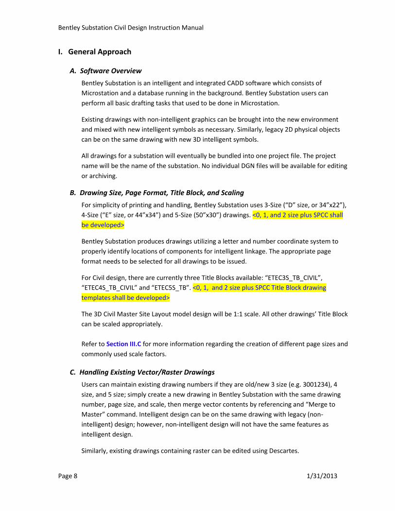
B. Drawing Size, Page Format, Title Block, and Scaling
For simplicity of printing and handling, Bentley Substation uses 3-Size (“D” size, or 34”x22”),
4-Size (“E” size, or 44”x34”) and 5-Size (50”x30”) drawings. <0, 1, and 2 size plus SPCC shall
be developed>
Bentley Substation produces drawings utilizing a letter and number coordinate system to
properly identify locations of components for intelligent linkage. The appropriate page
format needs to be selected for all drawings to be issued.
For Civil design, there are currently three Title Blocks available: “ETEC3S_TB_CIVIL”,
“ETEC4S_TB_CIVIL” and “ETEC5S_TB”. <0, 1, and 2 size plus SPCC Title Block drawing
templates shall be developed>
The 3D Civil Master Site Layout model design will be 1:1 scale. All other drawings’ Title Block
can be scaled appropriately.
Refer to Section III.C for more information regarding the creation of different page sizes and
commonly used scale factors.
C. Handling Existing Vector/Raster Drawings
Users can maintain existing drawing numbers if they are old/new 3 size (e.g. 3001234), 4
size, and 5 size; simply create a new drawing in Bentley Substation with the same drawing
number, page size, and scale, then merge vector contents by referencing and “Merge to
Master” command. Intelligent design can be on the same drawing with legacy (non-
intelligent) design; however, non-intelligent design will not have the same features as
intelligent design.
Similarly, existing drawings containing raster can be edited using Descartes.
Bentley Substation Civil Design Instruction Manual
Page 9 1/31/2013
Refer to Appendix D for a procedure when an existing legacy Title Block needs to be
retained.
II. Design Approach
It’s important that project design be based on existing and approved design standards, not from
other projects when design standards are available. This means all applicable existing standards
will need to be modeled ahead of time. For creation of standard (and nonstandard) 3D symbols,
a request should be made to the Civil Bentley Administrator.
For the Civil Arrangement of Foundation or Grading Plan design, users can start the design by
placing 3D symbols (i.e., foundations) from the catalog into the Civil Master Site Layout model.
Final construction drawings will be made by referencing the Civil Master Site Layout model.
Dimensions, text and Foundation Item Number (balloon number) will be placed manually on the
final construction drawings to be issued.
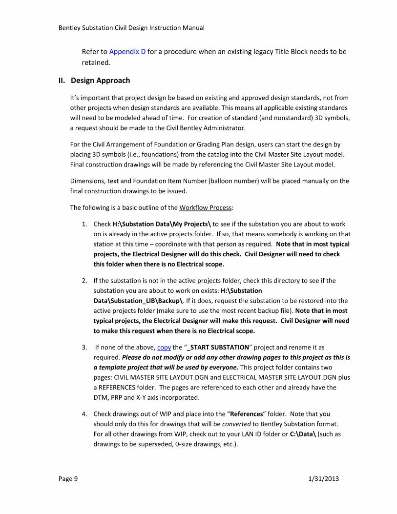
The following is a basic outline of the Workflow Process:
1. Check H:\Substation Data\My Projects\ to see if the substation you are about to work
on is already in the active projects folder. If so, that means somebody is working on that
station at this time – coordinate with that person as required. Note that in most typical
projects, the Electrical Designer will do this check. Civil Designer will need to check
this folder when there is no Electrical scope.
2. If the substation is not in the active projects folder, check this directory to see if the
substation you are about to work on exists: H:\Substation
Data\Substation_LIB\Backup\. If it does, request the substation to be restored into the
active projects folder (make sure to use the most recent backup file). Note that in most
typical projects, the Electrical Designer will make this request. Civil Designer will need
to make this request when there is no Electrical scope.
3. If none of the above, copy the “_START SUBSTATION” project and rename it as
required. Please do not modify or add any other drawing pages to this project as this is
a template project that will be used by everyone. This project folder contains two
pages: CIVIL MASTER SITE LAYOUT.DGN and ELECTRICAL MASTER SITE LAYOUT.DGN plus
a REFERENCES folder. The pages are referenced to each other and already have the
DTM, PRP and X-Y axis incorporated.
4. Check drawings out of WIP and place into the “References” folder. Note that you
should only do this for drawings that will be converted to Bentley Substation format.
For all other drawings from WIP, check out to your LAN ID folder or C:\Data\ (such as
drawings to be superseded, 0-size drawings, etc.).
Bentley Substation Civil Design Instruction Manual
Page 10 1/31/2013
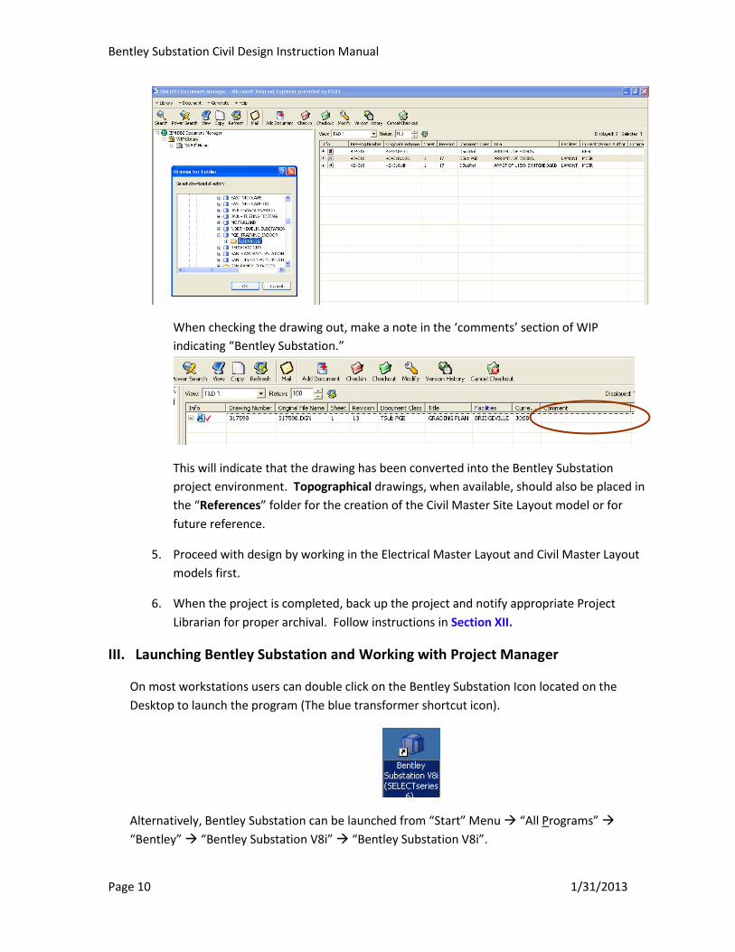
When checking the drawing out, make a note in the ‘comments’ section of WIP
indicating “Bentley Substation.”
This will indicate that the drawing has been converted into the Bentley Substation
project environment. Topographical drawings, when available, should also be placed in
the “References” folder for the creation of the Civil Master Site Layout model or for
future reference.
5. Proceed with design by working in the Electrical Master Layout and Civil Master Layout
models first.
6. When the project is completed, back up the project and notify appropriate Project
Librarian for proper archival. Follow instructions in Section XII.
III. Launching Bentley Substation and Working with Project Manager
On most workstations users can double click on the Bentley Substation Icon located on the
Desktop to launch the program (The blue transformer shortcut icon).
Alternatively, Bentley Substation can be launched from “Start” Menu “All Programs”
“Bentley” “Bentley Substation V8i” “Bentley Substation V8i”.

Bentley Substation Civil Design Instruction Manual
Page 11 1/31/2013
Once Bentley Substation has launched, the “Project Manager” dialog appears as shown below.
The following tasks can be done by the “Project Manager”:
- Restore a project from backup/archive
- Create a new project and new drawing page
- Copy a new project or drawing page
- Rename and Modify a project or drawing page
- Run Reports (i.e., the Foundation Data Sheet report)
A. Restoring a Project from Backup
On a regular production run, after a project has been completed using Bentley Substation, it
will be backed up into one single file which will be archived. This archived project needs to
be restored in Bentley Substation’s Project Manager before it can be worked on again.
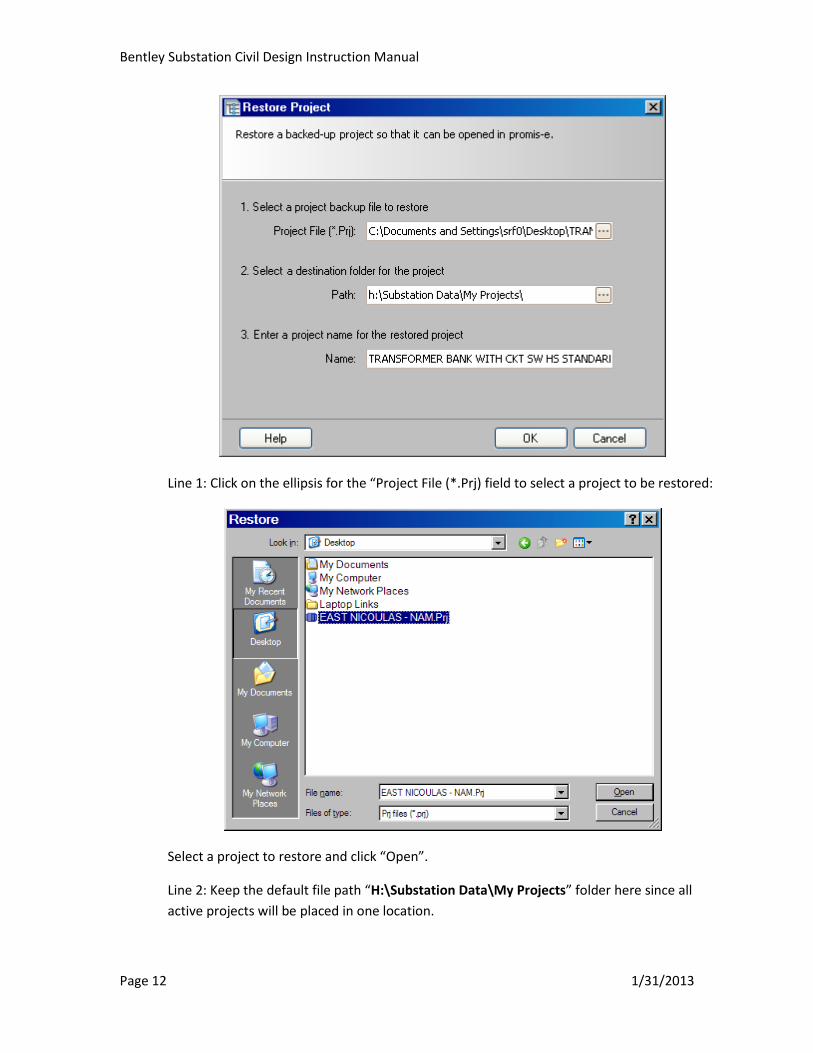
On “Project Manager”, point to “File” “Restore”, the “Restore Project” dialog box appears
Bentley Substation Civil Design Instruction Manual
Page 12 1/31/2013
Line 1: Click on the ellipsis for the “Project File (*.Prj) field to select a project to be restored:
Select a project to restore and click “Open”.
Line 2: Keep the default file path “H:\Substation Data\My Projects” folder here since all
active projects will be placed in one location.
Bentley Substation Civil Design Instruction Manual
Page 13 1/31/2013
Line 3: Assign a new project name if needed; otherwise, the name for the project to be
restored will be kept.
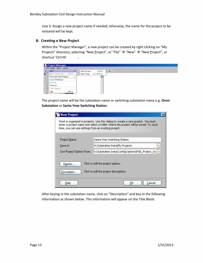
B. Creating a New Project
Within the “Project Manager”, a new project can be created by right clicking on “My
Projects” directory, selecting “New Project”, or “File” “New” “New Project”, or
shortcut ‘Ctrl+N’ .
The project name will be the substation name or switching substation name e.g. Orosi
Substation or Santa Ynez Switching Station.
After keying in the substation name, click on “Description” and key-in the following
information as shown below. This information will appear on the Title Block.

Bentley Substation Civil Design Instruction Manual
Page 14 1/31/2013
C. Creating a New Drawing Page
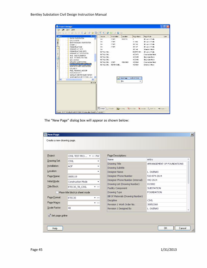
After successfully creating a new project, the “New Page” dialog box immediately appears
which asks the user to create a new drawing page.

Bentley Substation Civil Design Instruction Manual
Page 15 1/31/2013
1. Project – Defaults to the name of the project which is also the name of the facility
(Substation, Switching Station, etc.). Ensure you are creating the drawing in the proper
project.
2. Drawing Set – Type in “CIVIL” for all Civil drawings so they are easily recognized within
Project Manager.
3. Installation – Type in drawing type: Arrangement of Foundations, Grading Plan,
Foundation Data Sheet, Structural, SPCC, etc.
4. Location – Typically Leave Blank.
Note:
Drawing Set, Installation and Location fields are intended to be used for organizing the
drawings, and to be able to filter and search in the future. Civil is populating these fields
with different information than the Electricals. Refer to latest edition of Electrical Manual
for more details on what information Electricals use in these fields.
Do not use special characters for Installation or Location (#, &, commas, apostrophes,
colons, semicolons, parentheses, *, etc)
5. Page Name – Type in a Page Name, most likely will be a PG&E drawing number
beginning with 3-, 4-, or 5-, or “Civil Master Site Layout” for the Civil Master Site Layout
drawing.
6. Initial Mode – Choose the type of drawing you are creating from the list of available
types. “3D Layout” for the Civil Master Site Layout; “Construction Mode” for all other
Civil Construction Drawings.
7. Title Block – Select the appropriate size for drawings to be issued. Leave Title Block
blank for 3D Layout.
a. For 3-size drawings, choose ETEC3S_TB_CIVIL
b. For 4-size drawings, choose ETEC4S_TB_CIVIL
c. For 5-size drawings, choose ETEC5S_TB.
Note that depending on your settings, you may need to choose ellipses at the right hand
side of the Title Block field, left click on it. This brings up the “Select Title Block” dialog
box. Within the “Catalog Tree” panel, select “Master Catalog 2d” and double click with
left mouse button, then select the appropriate Title Block from the list.
Refer to Appendix D for what to do if you have an existing drawing that has an older
legacy Title Block that you would like to retain or if you have a 0, 1 or 2 size drawing.
8. Place Title Block in sheet mode – ensure this box is NOT checked for new drawings.
9. Page Format – Select the appropriate size for drawings to be issued. Select as follows:
a. For Civil Master Site Layout, choose 3D Layout.

Bentley Substation Civil Design Instruction Manual
Page 16 1/31/2013
b. For 3-size drawings, choose ETEC3S,
c. For 4-size drawings, choose ETEC4S
d. For 5-size drawings, choose ETEC5S.
10. Page Macro – Leave Blank (highlight and clear any text in this field) unless an established
page macro exists, not typical for Civil drawings. Refer to latest edition of Electrical
manual for more information on page macros.
11. Scale Factor – This is where you set your page scale. For the Civil Master Site Layout,
the Scale Factor should be set to 1. For Construction Drawings, type in the appropriate
scale factor for the drawing page. The following are some common scale factor values:
Scale Scale Factor Scale Scale Factor
1’ = 1’-0” 1 1/16” = 1’-0” 192
3” = 1’-0” 3 1” = 10’ 120
2” = 1’-0” 6 1” = 20’ 240
1½” = 1’-0” 8 1” = 30’ 360
1” = 1’-0” 12 1” = 40’ 480
¾” = 1’-0” 16 1” = 50’ 600
½” = 1’-0” 24 1” = 60’ 720
3/8” = 1’-0” 32 1” = 100’ 1200
¼” = 1’-0” 48 1” = 200’ 2400
3/16” = 1’-0” 64 1” = 400’ 4800
1/8” = 1’-0” 96 1” = 500’ 6000
3/32” = 1’-0” 128 1” = 1000’ 12000
12. Set page online – This needs to always be checked
13. Page Descriptions – The information entered here will appear in various spots on the
Title Block. Information can be entered here, or at a later time by either selecting
“Modify Page” after right clicking on the drawing listed in the Project Manager or right
clicking anywhere on the Title Block in the active drawing.
Once all these fields are properly filled out, clicking “OK” will open the new drawing page.
Bentley Substation Civil Design Instruction Manual
Page 17 1/31/2013
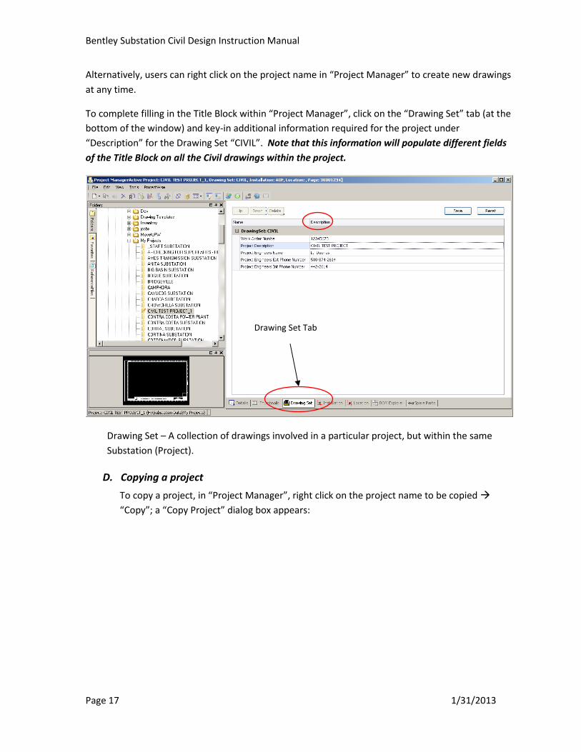
Alternatively, users can right click on the project name in “Project Manager” to create new drawings
at any time.
To complete filling in the Title Block within “Project Manager”, click on the “Drawing Set” tab (at the
bottom of the window) and key-in additional information required for the project under
“Description” for the Drawing Set “CIVIL”. Note that this information will populate different fields
of the Title Block on all the Civil drawings within the project.
Drawing Set – A collection of drawings involved in a particular project, but within the same
Substation (Project).
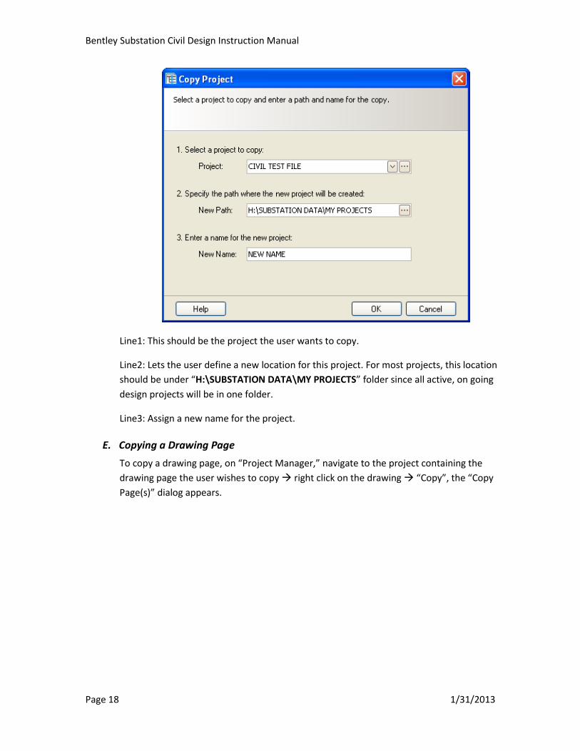
D. Copying a project
To copy a project, in “Project Manager”, right click on the project name to be copied
“Copy”; a “Copy Project” dialog box appears:
Drawing Set Tab
Bentley Substation Civil Design Instruction Manual
Page 18 1/31/2013
Line1: This should be the project the user wants to copy.
Line2: Lets the user define a new location for this project. For most projects, this location
should be under “H:\SUBSTATION DATA\MY PROJECTS” folder since all active, on going
design projects will be in one folder.
Line3: Assign a new name for the project.
E. Copying a Drawing Page
To copy a drawing page, on “Project Manager,” navigate to the project containing the
drawing page the user wishes to copy right click on the drawing “Copy”, the “Copy
Page(s)” dialog appears.

Bentley Substation Civil Design Instruction Manual
Page 19 1/31/2013
The most important thing to do first is to select the destination for the project where you
want to copy the drawing(s) to. Left click on the small triangle at the right hand side of the
“Project” field, select within the list of folder locations, or click on the ellipses to navigate to
the correct folder location. Fill in the rest of the fields as needed or leave “(Keep Existing)”.
If drawing description needs to be changed, click on the “Description” button and key-in all
drawing info/description. Click “OK” when done.
For the “Page Options” field, “Maintain Device ID” should be checked and the pull down
menu should have “Tag Only” selected.
The “Set Pages Online” box should also be checked.
For the “Wire Number Options” field, leave options shown in above image
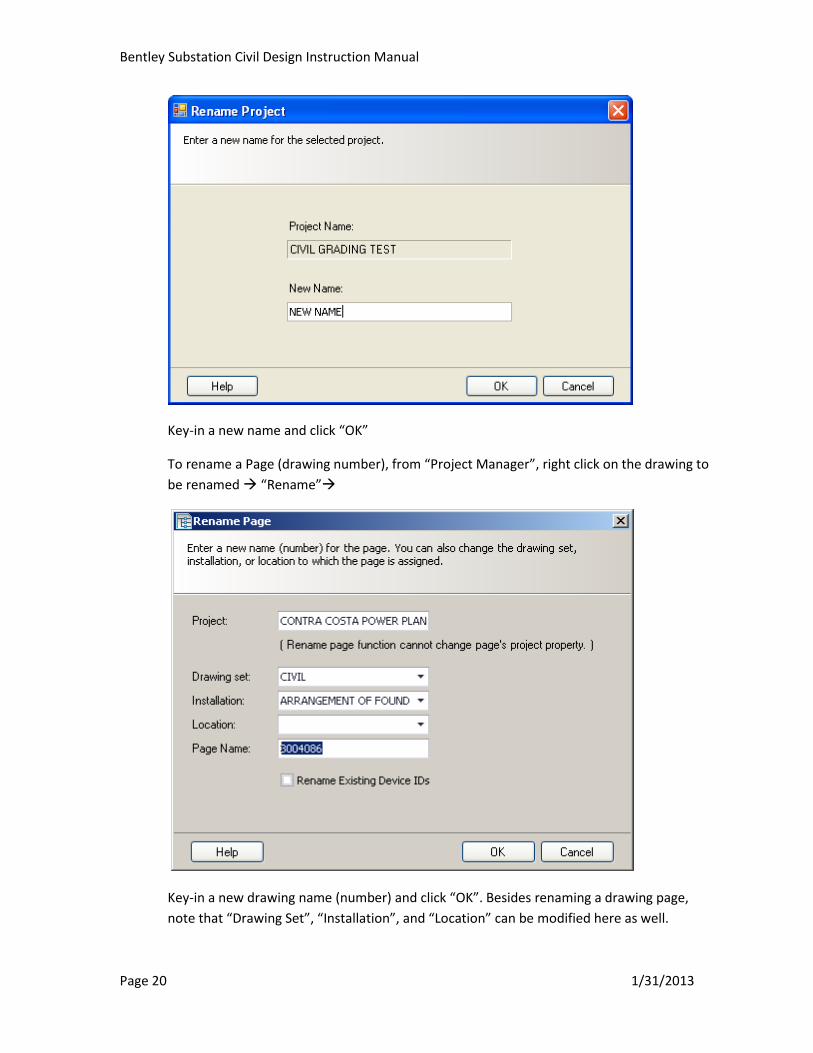
F. Rename a Project or Drawing Page
To rename a project, from “Project Manager”, right click on the project to be renamed
“Rename”
Bentley Substation Civil Design Instruction Manual
Page 20 1/31/2013
Key-in a new name and click “OK”
To rename a Page (drawing number), from “Project Manager”, right click on the drawing to
be renamed “Rename”
Key-in a new drawing name (number) and click “OK”. Besides renaming a drawing page,
note that “Drawing Set”, “Installation”, and “Location” can be modified here as well.
Bentley Substation Civil Design Instruction Manual
Page 21 1/31/2013
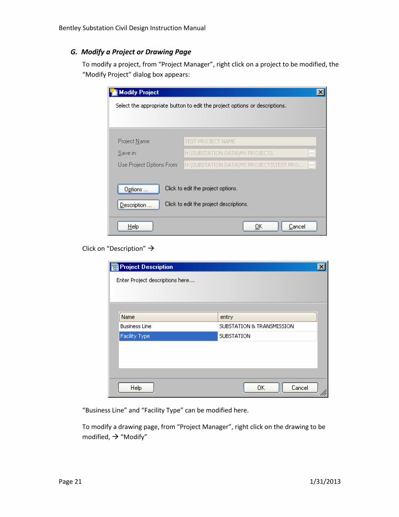
G. Modify a Project or Drawing Page
To modify a project, from “Project Manager”, right click on a project to be modified, the
“Modify Project” dialog box appears:
Click on “Description”
“Business Line” and “Facility Type” can be modified here.
To modify a drawing page, from “Project Manager”, right click on the drawing to be
modified, “Modify”

Bentley Substation Civil Design Instruction Manual
Page 22 1/31/2013
All active fields can be modified here. Note: to modify inactive fields (Project:, Drawing Set:,
Installation:, Location:, Page Name:), use the “Rename” command.
Note: the use of the “Place Title Block in sheet mode” check box is no longer necessary.
Please do not check this box under any circumstances. Failure to do so may result in losing
work.
H. Running Reports
Foundation Data Sheet Reports can be run in Project Manager or from a drawing page.
Refer to Section IX for more detailed instructions on Running Report commands and
features.
IV. Designing with Existing Vector/Raster Drawings
A. General Method
Since Bentley Substation carries full Microstation features, modification of raster and vector
files will be handled similarly to how Microstation handled them.
After vector files are copied to a Bentley Substation drawing by “Referencing” and “Merge
to Master” commands, users can still use familiar drawing tools to modify vector contents
Bentley Substation Civil Design Instruction Manual
Page 23 1/31/2013
just like in Microstation. New intelligent symbols can be combined with non-intelligent
(vector) graphics.
B. Bringing in Existing Vector Files to a Bentley Substation Drawing
Users should place the existing raster/vector files in the “References” folder within the
project’s main folder. This folder contains all drawings checked out from WIP that are to be
converted into Bentley Substation format; this includes both vector and raster files. Note
that Topographical files should also be placed in the “References” folder.
In “Project Manager”, open a drawing (this becomes the active Bentley Substation drawing)
that the user wishes to bring existing vector content into. It’s important to ensure that the
active Bentley Substation drawing’s scale is compatible with the referenced vector drawing
scale. Run the “Reference”( ) command
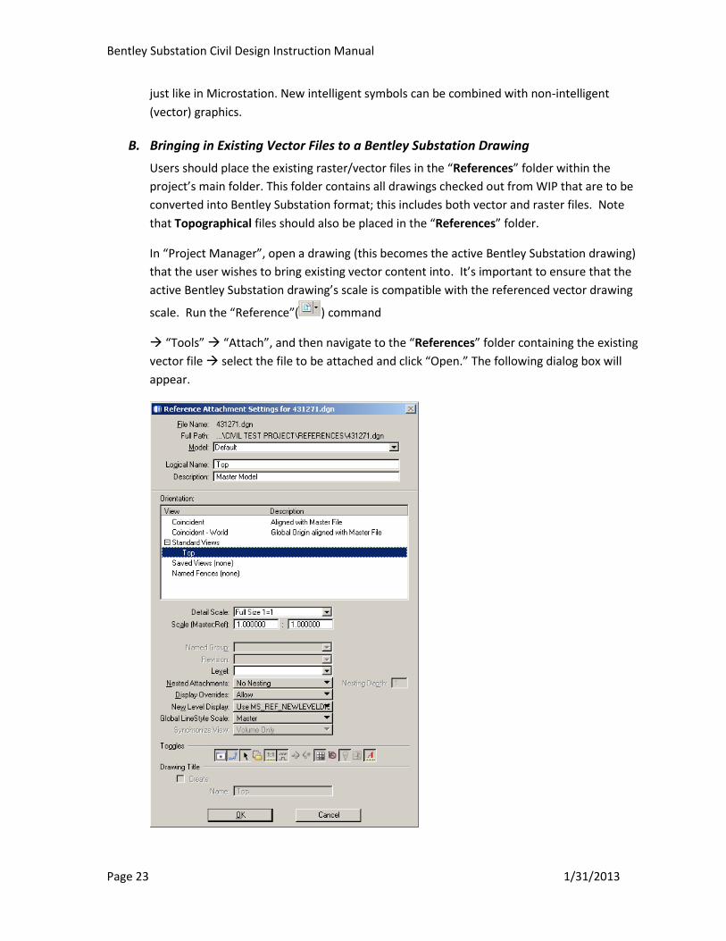
“Tools” “Attach”, and then navigate to the “References” folder containing the existing
vector file select the file to be attached and click “Open.” The following dialog box will
appear.

Bentley Substation Civil Design Instruction Manual
Page 24 1/31/2013
Select “Top” under the “Orientation”, “Standard Views” section, verify “Detail Scale”,
“Nested Attachments” and “Nesting Depth” as required. Refer to Section VIII for additional
discussion on “Nested Attachments”. Select “OK”.
Place the cursor within the active drawing at the spot where the referenced drawing is to be
located, and left click.
Once the vector file has been referenced in, use clip reference to exclude unwanted data
(such as drawing numbers in the border, revision block info, extraneous data outside the
format, etc.). Then, merge the vector drawing into the Bentley Substation drawing.
From the “References” dialog box, with the drawing to be merged highlighted select “Tools”
“Merge into Master”
Note: if the vector file to be referenced and merged to the Bentley Substation drawing
contains a raster file, that raster file will be referenced into the Bentley Substation drawing
as well. Click on the “Raster Manager” command to verify.
The example below shows the raster file listed in the Raster Manager. Basic raster file
manipulations such as move, scale, copy, rotate…can be done using Descartes tools.

Bentley Substation Civil Design Instruction Manual
Page 25 1/31/2013
Verify the raster file name is correct and that the path to the raster file is pointing to the
correct file location. To verify path, right click on the file name within “Raster Manager” and
select “File Name”.
This will bring up the following dialog box,
Select the magnifying glass, which will bring up the “Find Raster File” dialog box.
Navigate to and select the correct file, then click “Open”

Bentley Substation Civil Design Instruction Manual
Page 26 1/31/2013
The full file path should now be shown. Verification of the path is important in case the
Raster file had been moved from its’ originally saved location. If the above steps are not
done the raster drawing file may become unattached from the vector file drawing. If
this happens, then the user will need to manually reattach the raster file.
C. Placing Symbols into Vector/Raster Graphics
For Arrangement of Foundations or Grading Plans, insert 3D objects in the Civil Master Site
Layout model, then reference that 3D drawing into the construction drawing containing
raster/vector graphics. Refer to Section VI for more details.
V. Section NOT used in Civil Manual
VI. Designing the Civil Master Site Layout
Historically, all drawings were stored individually and could not be tied or linked to one another.
Bentley Substation uses a “project setting” where all information for one substation is stored
and archived together. This design approach allows items to be defined only once within the
project and referenced into various drawings and models throughout the project. For example,
the fence line, defined in the Civil Master Site layout, will be referenced into numerous
individual construction drawings. Any changes to the fence line will be done on the Civil Master
Site Layout and this change will echo throughout any drawings that use it as a reference.
The project setting also allows the Civil and Electrical master site layouts to be referenced
between each other for a real-time “overlay” at any point in the design process.
Below is a general overview of the interdisciplinary design outline that shows how the Civil
Master Layout model is utilized (arrows represent referencing):
Bentley Substation Civil Design Instruction Manual
Page 27 1/31/2013
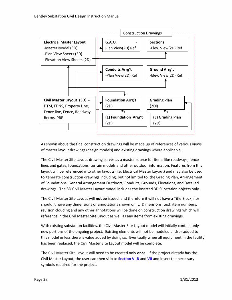
As shown above the final construction drawings will be made up of references of various views
of master layout drawings (design models) and existing drawings where applicable.
The Civil Master Site Layout drawing serves as a master source for items like roadways, fence
lines and gates, foundations, terrain models and other outdoor information. Features from this
layout will be referenced into other layouts (i.e. Electrical Master Layout) and may also be used
to generate construction drawings including, but not limited to, the Grading Plan, Arrangement
of Foundations, General Arrangement Outdoors, Conduits, Grounds, Elevations, and Detailed
drawings. The 3D Civil Master Layout model includes the inserted 3D Substation objects only.
The Civil Master Site Layout will not be issued, and therefore it will not have a Title Block, nor
should it have any dimensions or annotations shown on it. Dimensions, text, item numbers,
revision clouding and any other annotations will be done on construction drawings which will
reference in the Civil Master Site Layout as well as any items from existing drawings.
With existing substation facilities, the Civil Master Site Layout model will initially contain only
new portions of the ongoing project. Existing elements will not be modeled and/or added to
this model unless there is value added by doing so. Eventually when all equipment in the facility
has been replaced, the Civil Master Site Layout model will be complete.
The Civil Master Site Layout will need to be created only once. If the project already has the
Civil Master Layout, the user can then skip to Section VI.B and VII and insert the necessary
symbols required for the project.
Electrical Master Layout
-Master Model (3D)
-Plan View Sheets (2D)
-Elevation View Sheets (2D)
(2D)(2D)
G.A.O. -
Plan View(2D) Ref
Sections
-Elev. View(2D) Ref
Civil Master Layout (3D) -
DTM, FDNS, Property Line,
Fence line, Fence, Roadway,
Berms, PRP
Conduits Arrg’t
-Plan View(2D) Ref
Ground Arrg’t
-Elev. View(2D) Ref
Foundation Arrg’t
(2D)
Grading Plan
(2Dl)
(E) Foundation Arrg’t
(2D)
(E) Grading Plan
(2D)
Construction Drawings
Bentley Substation Civil Design Instruction Manual
Page 28 1/31/2013
A. Creating a New Civil 3D Layout Page
Note: The following sections describe how to create the Civil Master Site Layout page from
scratch. Generally it is much easier to copy the template page “CIVIL MASTER SITE
LAYOUT” located in the folder “_START SUBSTATION” in “My Projects”. This template
page already contains the DTM, PRP, and the X and Y Axis.
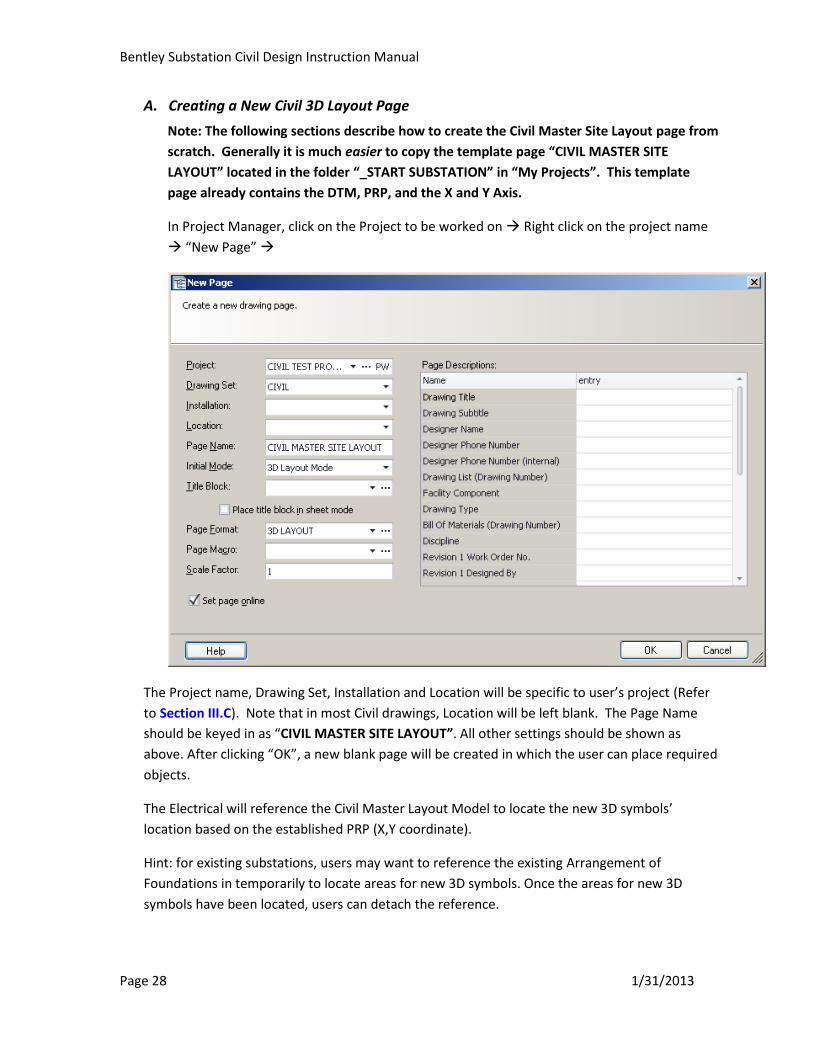
In Project Manager, click on the Project to be worked on Right click on the project name
“New Page”
The Project name, Drawing Set, Installation and Location will be specific to user’s project (Refer
to Section III.C). Note that in most Civil drawings, Location will be left blank. The Page Name
should be keyed in as “CIVIL MASTER SITE LAYOUT”. All other settings should be shown as
above. After clicking “OK”, a new blank page will be created in which the user can place required
objects.
The Electrical will reference the Civil Master Layout Model to locate the new 3D symbols’
location based on the established PRP (X,Y coordinate).
Hint: for existing substations, users may want to reference the existing Arrangement of
Foundations in temporarily to locate areas for new 3D symbols. Once the areas for new 3D
symbols have been located, users can detach the reference.

Bentley Substation Civil Design Instruction Manual
Page 29 1/31/2013
If components needed for the project are available in the Master Catalog 3D catalog, follow
Section VII to insert 3D objects. If components are not available, submit 3D symbol requests to
the Civil Bentley Substation Administrator.
B. Creating a 3D Civil Master Site Layout using Elements from a 3D Topographical
drawing
At this point a new, blank Civil Master Layout page should have been created and a blank 3D
model (black screen with x,y &z coordinates) should be displayed on the screen.
Use the “Reference” command to reference in the 3D Topographical drawing which
should be located within the “References” folder.
Typically many elements shown in the “topo” drawing will not be required to be part of
the Civil Master Site Layout. Only once the intended levels are selected and shown is
the referenced “topo” merged to the Civil Master Site Layout.
Once the “topo” has been merged, manipulate any of the various elements into new
levels if required. Also create any new levels as required (Refer to Appendix B).
Continue to Section D to create the Digital Terrain Model (DTM) if required for the
project.
Note -If regrading is required this file could be manipulated with a 3rd party software
program such as GeoPak. Alternatively the file could be converted to a 2D file,
manipulated, and then follow the procedures in the next section.
C. Creating a 3D Master Site Layout from an Existing Grading Plan
Creating the 3D Civil Master Layout from an existing 2D vector grading plan is done in a
similar fashion as the process used to create one from a Topographical drawing. The 2D
vector file should be referenced into the 3D model of the Civil Master Site Layout. Existing
elements from that drawing (fenceline, x-y axis, etc.) should be copied (or merged) into the
3D Civil Master Site Layout.
To generated a 3D DTM from existing contour, the contours will need to be moved to their
correct elevation. To do this, each contour should be selected individually, then select the
element information tool ( ) or alternatively select “Element””Information”. The
following dialogue box appears.

Bentley Substation Civil Design Instruction Manual
Page 30 1/31/2013
Under the Geometry tab, change the elevation field that is circled above to match the
correct elevation of the specific contour.
Any new elements (Contours, Contour Numbers, Property Line, X-Y axis) should also be
grouped into specific levels if they are not already done so.
Once all contours are moved to their respective elevations and then grouped together in the
same Level, the DTM should be created using the method described in the next section.
D. Creating the DTM
The DTM (Digital Terrain Model) represents the ground surface and is typically generated
from either contours or spot elevations.
The Contours and/or Spot elevations should already be isolated on their own Level and
located at the proper elevation (z value).
Tip- If any contour is circular and ends up back upon itself, use the ‘”break element” tool on
any point of the contour. This prevents areas within the contour to appear “pond-like”
when the 3D file is displayed as “smooth”.
Select the required Contours or Spot Elevations that will be used to generate the DTM using
the element selection tool as mentioned above. These elements should already be assigned
to their own level.
Bentley Substation Civil Design Instruction Manual
Page 31 1/31/2013
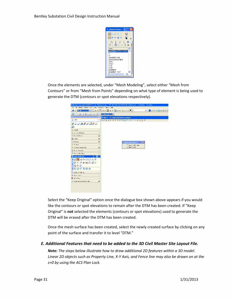
Once the elements are selected, under “Mesh Modeling”, select either “Mesh from
Contours” or from “Mesh from Points” depending on what type of element is being used to
generate the DTM (contours or spot elevations respectively).
Select the “Keep Original” option once the dialogue box shown above appears if you would
like the contours or spot elevations to remain after the DTM has been created. If “Keep
Original” is not selected the elements (contours or spot elevations) used to generate the
DTM will be erased after the DTM has been created.
Once the mesh surface has been created, select the newly created surface by clicking on any
point of the surface and transfer it to level “DTM.”
E. Additional Features that need to be added to the 3D Civil Master Site Layout File.
Note: The steps below illustrate how to draw additional 2D features within a 3D model.
Linear 2D objects such as Property Line, X-Y Axis, and Fence line may also be drawn on at the
z=0 by using the ACS Plan Lock.
Bentley Substation Civil Design Instruction Manual
Page 32 1/31/2013
To do this ensure that you in the Top View( ). Then select. Now it is possible to draw in
a 2D plane.
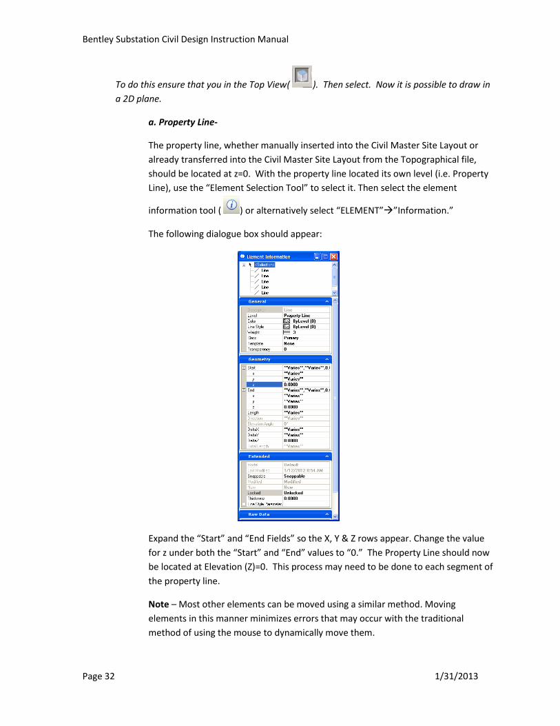
a. Property Line-
The property line, whether manually inserted into the Civil Master Site Layout or
already transferred into the Civil Master Site Layout from the Topographical file,
should be located at z=0. With the property line located its own level (i.e. Property
Line), use the “Element Selection Tool” to select it. Then select the element
information tool ( ) or alternatively select “ELEMENT””Information.”
The following dialogue box should appear:
Expand the “Start” and “End Fields” so the X, Y & Z rows appear. Change the value
for z under both the “Start” and “End” values to “0.” The Property Line should now
be located at Elevation (Z)=0. This process may need to be done to each segment of
the property line.
Note – Most other elements can be moved using a similar method. Moving
elements in this manner minimizes errors that may occur with the traditional
method of using the mouse to dynamically move them.
Bentley Substation Civil Design Instruction Manual
Page 33 1/31/2013
b. X-Y Axis-
The user will need to establish the location of the X-Y axis. The X-Y axis will show up
on all plan views of construction drawings and like the Property Line, it also should
also be located at Elevation (Z) =0
c. Fence line-
The user will also need to establish the location of the Fence Line. The Fence Line
will show up on all plan views of construction drawings and like the Property Line
and the X-Y Axis, it also should also be located at Elevation (Z) =0.
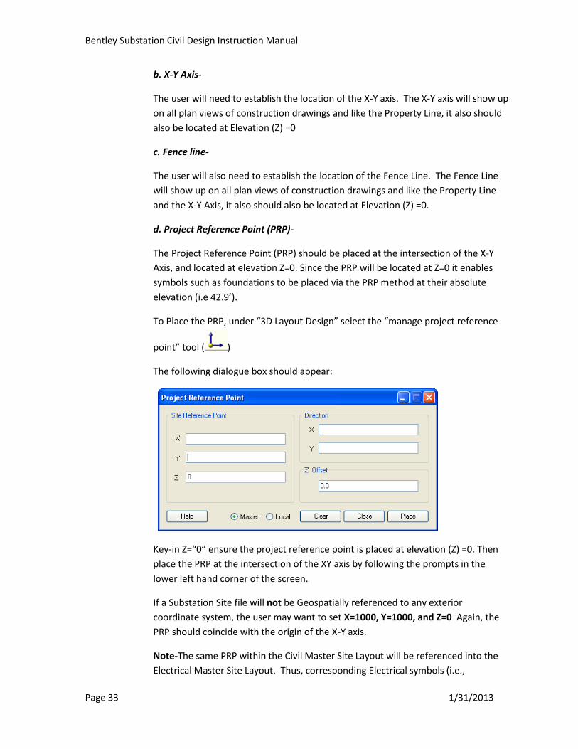
d. Project Reference Point (PRP)-
The Project Reference Point (PRP) should be placed at the intersection of the X-Y
Axis, and located at elevation Z=0. Since the PRP will be located at Z=0 it enables
symbols such as foundations to be placed via the PRP method at their absolute
elevation (i.e 42.9’).
To Place the PRP, under “3D Layout Design” select the “manage project reference
point” tool ( )
The following dialogue box should appear:
Key-in Z=“0” ensure the project reference point is placed at elevation (Z) =0. Then
place the PRP at the intersection of the XY axis by following the prompts in the
lower left hand corner of the screen.
If a Substation Site file will not be Geospatially referenced to any exterior
coordinate system, the user may want to set X=1000, Y=1000, and Z=0 Again, the
PRP should coincide with the origin of the X-Y axis.
Note-The same PRP within the Civil Master Site Layout will be referenced into the
Electrical Master Site Layout. Thus, corresponding Electrical symbols (i.e.,
Bentley Substation Civil Design Instruction Manual
Page 34 1/31/2013
structures) and Civil symbols (i.e., foundations) placed relative to the same PRP
should coincide with one another when the Electrical Master Layout and Civil
Master Layout are referenced between one another.
EXTREMELY IMPORTANT- Ensure that the PRP is correctly aligned with the X-Y
axis. When 3D symbols are placed, their orientation is established according to the
orientation of the PRP.
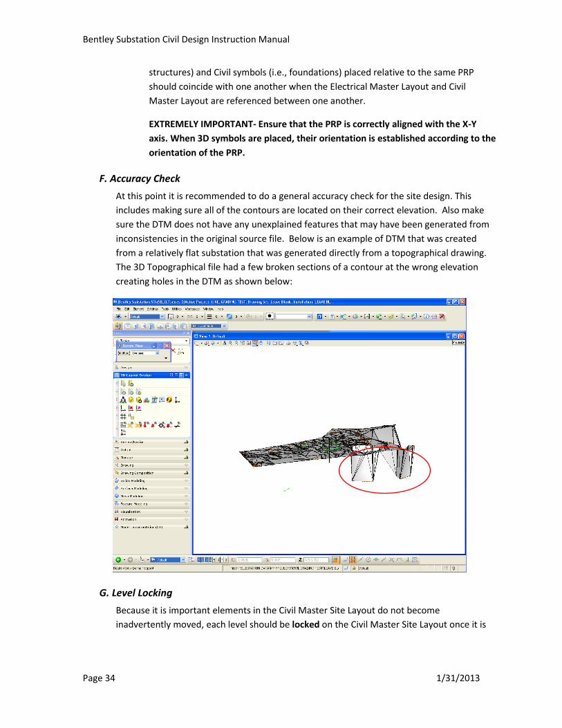
F. Accuracy Check
At this point it is recommended to do a general accuracy check for the site design. This
includes making sure all of the contours are located on their correct elevation. Also make
sure the DTM does not have any unexplained features that may have been generated from
inconsistencies in the original source file. Below is an example of DTM that was created
from a relatively flat substation that was generated directly from a topographical drawing.
The 3D Topographical file had a few broken sections of a contour at the wrong elevation
creating holes in the DTM as shown below:
G. Level Locking
Because it is important elements in the Civil Master Site Layout do not become
inadvertently moved, each level should be locked on the Civil Master Site Layout once it is

Bentley Substation Civil Design Instruction Manual
Page 35 1/31/2013
complete. To lock levels go “Tools””Levels” ”Level Manager” or alternatively select the
icon. Right click on which level that needs to be lock, the go to “Properties”.
Another dialogue box appears.
Select the box next to “Lock”
Bentley Substation Civil Design Instruction Manual
Page 36 1/31/2013
Alternatively, it is possible to lock multiple levels simultaneously by holding down the
“CTRL” key and selecting multiple levels at once. Then right click on one of the levels, select
properties, and then select “Lock”
The locked levels will need to be unlocked when future changes are required.
VII. Inserting 3D Objects
A. Insert Substation Object in the Civil Master Site Layout
Once the DTM has been created and is located on level “DTM”, it is now possible to place
objects relative to that surface according to the DTM method. (Alternatively, since the PRP
is set at z=0, when elements are placed via the PRP method they can be placed at the
absolute elevation.)
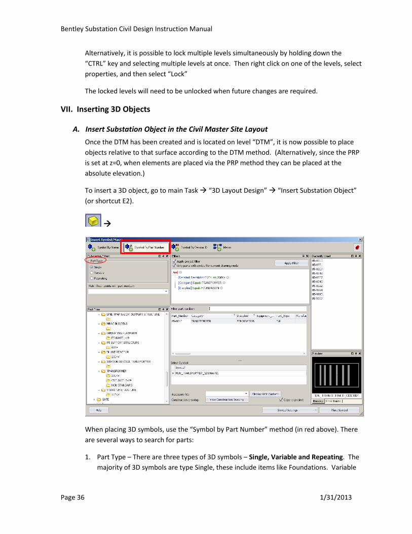
To insert a 3D object, go to main Task “3D Layout Design” “Insert Substation Object”
(or shortcut E2).
When placing 3D symbols, use the “Symbol by Part Number” method (in red above). There
are several ways to search for parts:
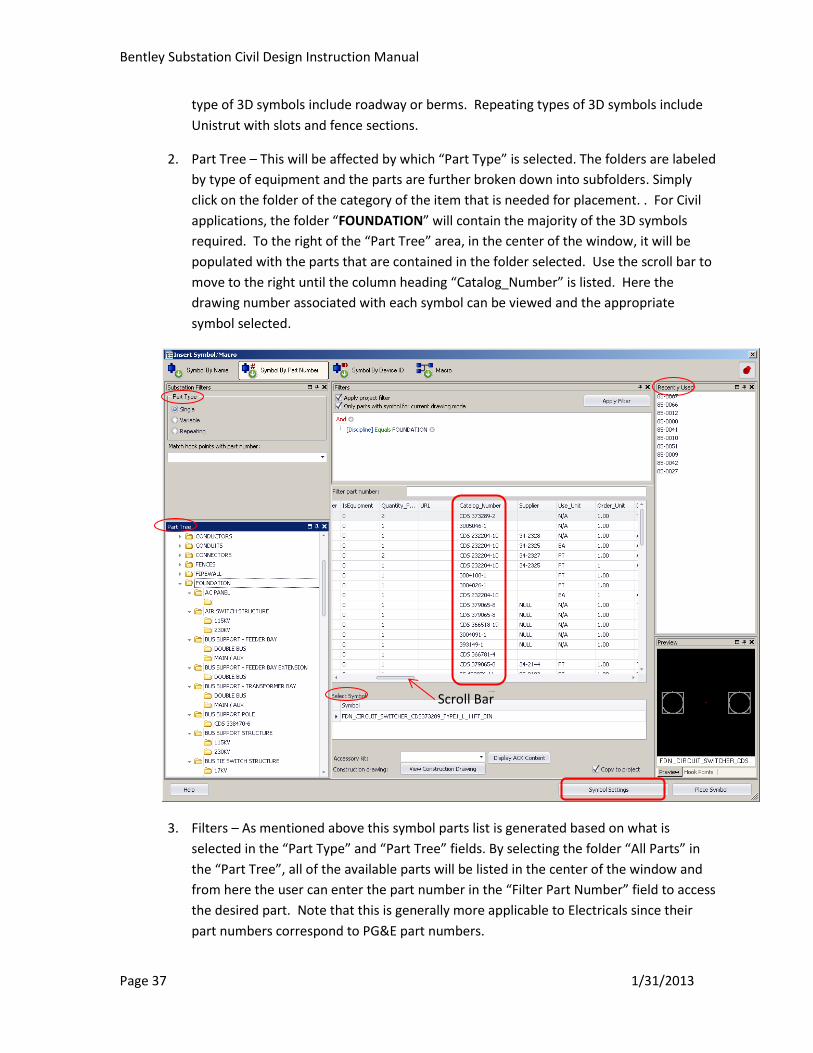
1. Part Type – There are three types of 3D symbols – Single, Variable and Repeating. The
majority of 3D symbols are type Single, these include items like Foundations. Variable
Bentley Substation Civil Design Instruction Manual
Page 37 1/31/2013
type of 3D symbols include roadway or berms. Repeating types of 3D symbols include
Unistrut with slots and fence sections.
2. Part Tree – This will be affected by which “Part Type” is selected. The folders are labeled
by type of equipment and the parts are further broken down into subfolders. Simply
click on the folder of the category of the item that is needed for placement. . For Civil
applications, the folder “FOUNDATION” will contain the majority of the 3D symbols
required. To the right of the “Part Tree” area, in the center of the window, it will be
populated with the parts that are contained in the folder selected. Use the scroll bar to
move to the right until the column heading “Catalog_Number” is listed. Here the
drawing number associated with each symbol can be viewed and the appropriate
symbol selected.
3. Filters – As mentioned above this symbol parts list is generated based on what is
selected in the “Part Type” and “Part Tree” fields. By selecting the folder “All Parts” in
the “Part Tree”, all of the available parts will be listed in the center of the window and
from here the user can enter the part number in the “Filter Part Number” field to access
the desired part. Note that this is generally more applicable to Electricals since their
part numbers correspond to PG&E part numbers.
Scroll Bar
Bentley Substation Civil Design Instruction Manual
Page 38 1/31/2013
4. Select Symbol – This area will list the available symbols depending on the Part Number
selected from the “Part Tree” or through using the “Filter part number” list above. Once
the appropriate symbol from the list (in the middle of the window) is identified, the user
will select it by left clicking on it.
5. Recently Used – This list is populated based on the parts the user has recently placed.
The user can simply select the item from this list and place as needed.
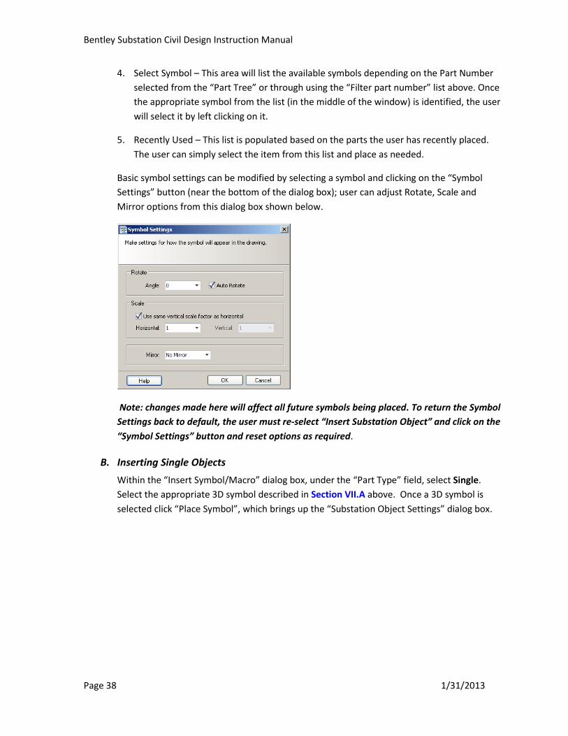
Basic symbol settings can be modified by selecting a symbol and clicking on the “Symbol
Settings” button (near the bottom of the dialog box); user can adjust Rotate, Scale and
Mirror options from this dialog box shown below.
Note: changes made here will affect all future symbols being placed. To return the Symbol
Settings back to default, the user must re-select “Insert Substation Object” and click on the
“Symbol Settings” button and reset options as required.
B. Inserting Single Objects
Within the “Insert Symbol/Macro” dialog box, under the “Part Type” field, select Single.
Select the appropriate 3D symbol described in Section VII.A above. Once a 3D symbol is
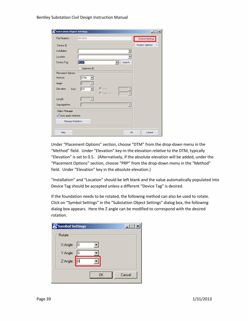
selected click “Place Symbol”, which brings up the “Substation Object Settings” dialog box.
Bentley Substation Civil Design Instruction Manual
Page 39 1/31/2013
Under “Placement Options” section, choose “DTM” from the drop-down menu in the
“Method” field. Under “Elevation” key-in the elevation relative to the DTM, typically
“Elevation” is set to 0.5. (Alternatively, if the absolute elevation will be added, under the
“Placement Options” section, choose “PRP” from the drop-down menu in the “Method”
field. Under “Elevation” key in the absolute elevation.)
“Installation” and “Location” should be left blank and the value automatically populated into
Device Tag should be accepted unless a different “Device Tag” is desired.
If the foundation needs to be rotated, the following method can also be used to rotate.
Click on “Symbol Settings” in the “Substation Object Settings” dialog box, the following
dialog box appears. Here the Z angle can be modified to correspond with the desired
rotation.
Bentley Substation Civil Design Instruction Manual
Page 40 1/31/2013
Click “OK” which will take the user back to the “Substation Object Settings”, Click the “OK”
button which will take the user back to the active drawing where the 3D symbol can be
placed. Within the Civil Master Site Layout place the 3D symbol in the location desired, then
left click. When done placing the foundation(s), right click to clear. This will take the user
back to the “Insert Symbol” dialog box where another 3D symbol can be selected. If no
further 3D symbols are required, exit this dialog box by clicking on the “X” in the upper right
hand of the dialog box.
Note: clicking on the red push pin located at the top right corner of the window of the “Insert
Symbol/Macro” dialog box toggles this dialog box from displaying again after users had
placed a symbol.
Note on symbol scaling: with a few exceptions, all symbols were created with 1:1 scale. This
means that if the user is inserting 3D symbols on a drawing other than the Civil Master
Layout (uses the 1:1 scale), the symbol may need to be scaled. This would not be a typical
scenario.
C. Inserting Variable Objects
Under the “3D Layout Design” tab, choose the “Insert Substation Object” command. Once
the “Insert Symbol/Macro” dialog opens up, under the “Part Type” field, select Variable.
Refer to “Inserting Variable Objects Section” in the Electrical Manual for an example that
places a variable rigid bus.
D. Inserting Repeating Objects
Under the “3D Layout Design” tab, choose the “Insert Substation Object” command. Once
the “Insert Symbol/Macro” dialog opens up, under the “Part Type” field, select Repeating.
The remaining steps are similar to inserting a Single Object, refer to Section VII.B above.
E. Assigning Balloon Numbers to Foundations.
After an object has been placed, it is possible to manually assign a balloon number
(Foundation Item Number) and also give the item a corresponding job number (refer next
section). This information will be used and exported to create the Foundation Data Sheet
report.
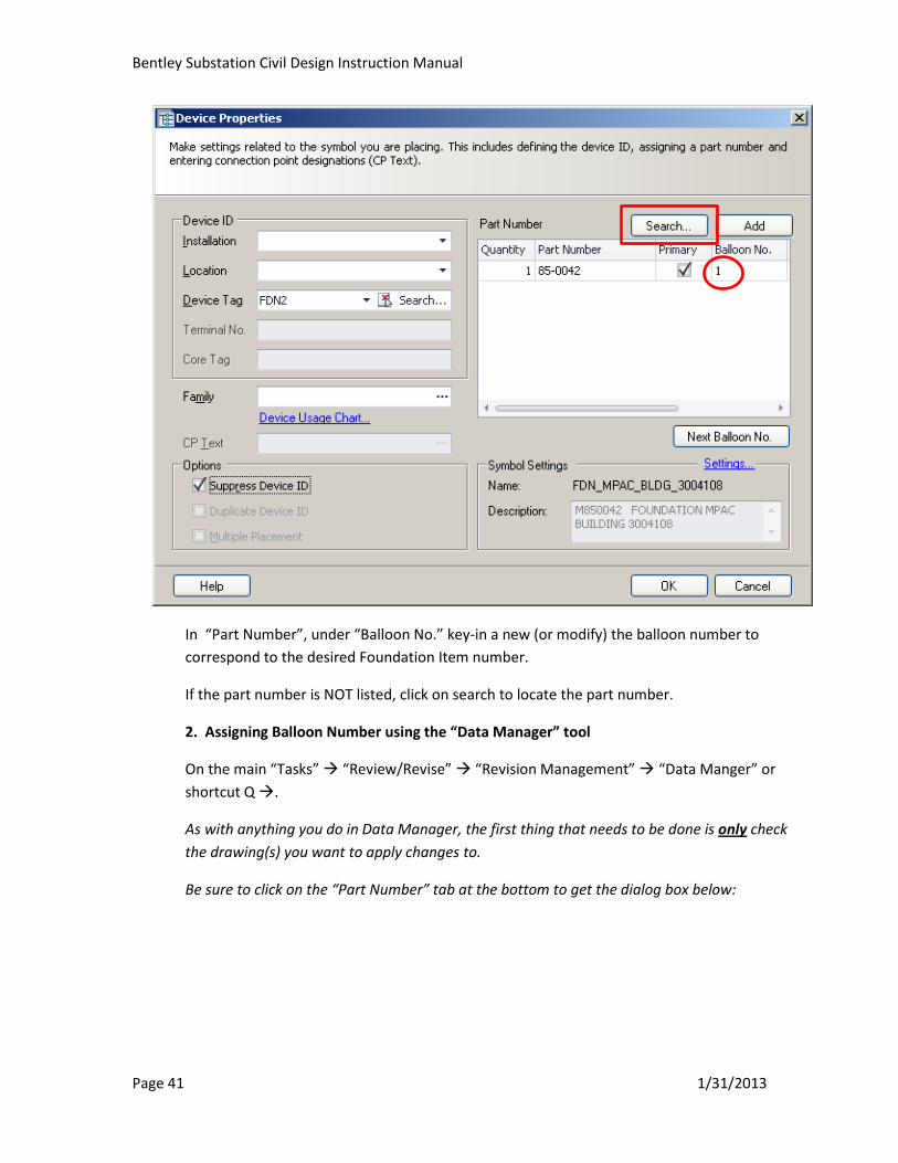
1. Assigning Balloon Number by “Device Properties” Dialog Box
To assign a balloon number: After a 3D symbol has been inserted on the 3D Civil Master Site
Layout drawing, right click on the 3D object and select “Device ID” this brings up the Dialog
box “Device Properties”.
Bentley Substation Civil Design Instruction Manual
Page 41 1/31/2013
In “Part Number”, under “Balloon No.” key-in a new (or modify) the balloon number to
correspond to the desired Foundation Item number.
If the part number is NOT listed, click on search to locate the part number.
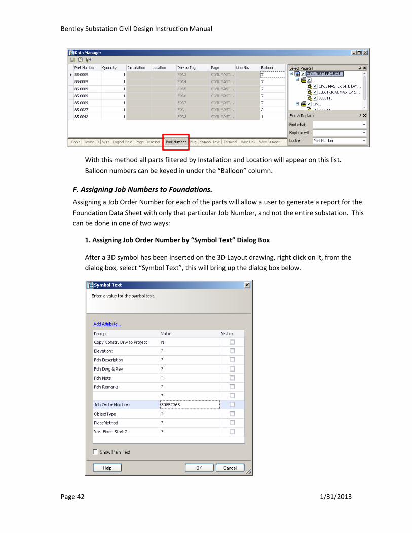
2. Assigning Balloon Number using the “Data Manager” tool
On the main “Tasks” “Review/Revise” “Revision Management” “Data Manger” or
shortcut Q .
As with anything you do in Data Manager, the first thing that needs to be done is only check
the drawing(s) you want to apply changes to.
Be sure to click on the “Part Number” tab at the bottom to get the dialog box below:
Bentley Substation Civil Design Instruction Manual
Page 42 1/31/2013
With this method all parts filtered by Installation and Location will appear on this list.
Balloon numbers can be keyed in under the “Balloon” column.
F. Assigning Job Numbers to Foundations.
Assigning a Job Order Number for each of the parts will allow a user to generate a report for the
Foundation Data Sheet with only that particular Job Number, and not the entire substation. This
can be done in one of two ways:
1. Assigning Job Order Number by “Symbol Text” Dialog Box
After a 3D symbol has been inserted on the 3D Layout drawing, right click on it, from the
dialog box, select “Symbol Text”, this will bring up the dialog box below.
Bentley Substation Civil Design Instruction Manual
Page 43 1/31/2013
Add/Modify the job order number for the foundation item by replacing the default value of
“?”. Leave the box under the heading “Visible” unchecked unless it is desired to display the
job number text on the symbol within the drawing.
Note that there is also other information that could be added such as Elevation, Foundation
description, etc. if desired.
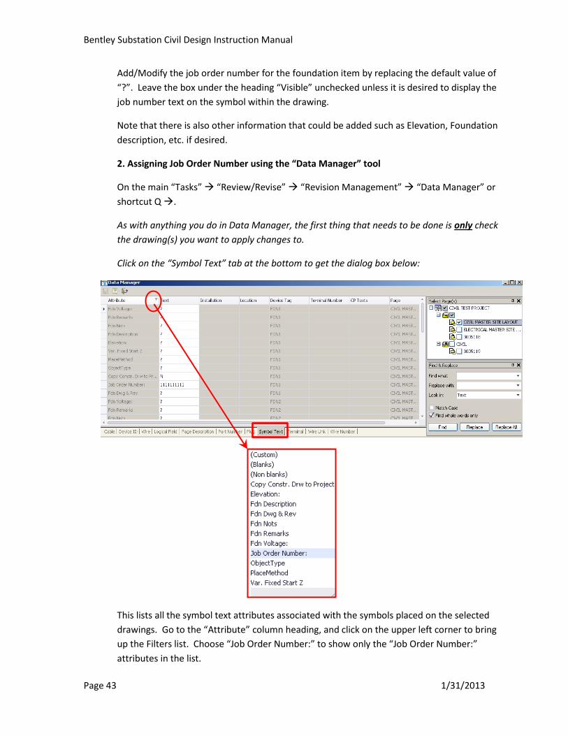
2. Assigning Job Order Number using the “Data Manager” tool
On the main “Tasks” “Review/Revise” “Revision Management” “Data Manager” or
shortcut Q .
As with anything you do in Data Manager, the first thing that needs to be done is only check
the drawing(s) you want to apply changes to.
Click on the “Symbol Text” tab at the bottom to get the dialog box below:
This lists all the symbol text attributes associated with the symbols placed on the selected
drawings. Go to the “Attribute” column heading, and click on the upper left corner to bring
up the Filters list. Choose “Job Order Number:” to show only the “Job Order Number:”
attributes in the list.
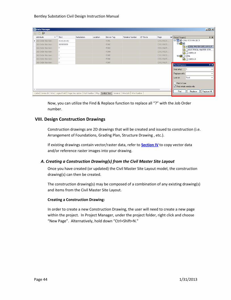
Bentley Substation Civil Design Instruction Manual
Page 44 1/31/2013
Now, you can utilize the Find & Replace function to replace all “?” with the Job Order
number.
VIII. Design Construction Drawings
Construction drawings are 2D drawings that will be created and issued to construction (i.e.
Arrangement of Foundations, Grading Plan, Structure Drawing , etc.).
If existing drawings contain vector/raster data, refer to Section IV to copy vector data
and/or reference raster images into your drawing.
A. Creating a Construction Drawing(s) from the Civil Master Site Layout
Once you have created (or updated) the Civil Master Site Layout model, the construction
drawing(s) can then be created.
The construction drawing(s) may be composed of a combination of any existing drawing(s)
and items from the Civil Master Site Layout.
Creating a Construction Drawing:
In order to create a new Construction Drawing, the user will need to create a new page
within the project. In Project Manager, under the project folder, right click and choose
“New Page”. Alternatively, hold down “Ctrl+Shift+N.”
Bentley Substation Civil Design Instruction Manual
Page 45 1/31/2013
The “New Page” dialog box will appear as shown below:
Bentley Substation Civil Design Instruction Manual
Page 46 1/31/2013
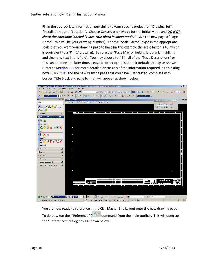
Fill in the appropriate information pertaining to your specific project for “Drawing Set”,
“Installation”, and “Location”. Choose Construction Mode for the Initial Mode and DO NOT
check the checkbox labeled “Place Title Block in sheet mode.” Give the new page a “Page
Name” (this will be your drawing number). For the “Scale Factor”, type in the appropriate
scale that you want your drawing page to have (in this example the scale factor is 48, which
is equivalent to a ¼” = 1’ drawing). Be sure the “Page Macro” field is left blank (highlight
and clear any text in this field). You may choose to fill in all of the “Page Descriptions” or
this can be done at a later time. Leave all other options at their default settings as shown.
(Refer to Section III.C for more detailed discussion of the information required in this dialog
box). Click “OK” and the new drawing page that you have just created, complete with
border, Title Block and page format, will appear as shown below.
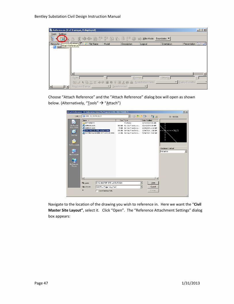
You are now ready to reference in the Civil Master Site Layout onto the new drawing page.
To do this, run the ‘”Reference” ( )command from the main toolbar. This will open up
the “References” dialog box as shown below.
Bentley Substation Civil Design Instruction Manual
Page 47 1/31/2013
Choose “Attach Reference” and the “Attach Reference” dialog box will open as shown
below. (Alternatively, “Tools” “Attach”)
Navigate to the location of the drawing you wish to reference in. Here we want the “Civil
Master Site Layout”, select it. Click “Open”. The “Reference Attachment Settings” dialog
box appears:

Bentley Substation Civil Design Instruction Manual
Page 48 1/31/2013
In the “Model” drop-down menu, select the model you wish to reference in. In this
example, we will be referencing in the “Default” model. In the “Detail Scale” field, make
sure “Full Size 1=1” is selected from the drop-down menu. Change the “Nested
Attachments” setting to “Live Nesting” and set the “Nesting Depth” value as appropriate.
**Note: The Depth of the Live Nesting may need to be changed when creating a
new page which references in another drawing that already contains a reference.
Set or change the “Nesting Depth” value as appropriate in order to maintain the
intelligence of all the references.
Tip- When referencing either a 2D or 3D model, choose “Top” under “Standard Views”
within the “Orientation” field to interactively place the reference within the active drawing.
If “Top” is not selected the reference may appear far from its’ intended location and the
reference may need to be moved within the active drawing by using “References””Move
Reference”

Bentley Substation Civil Design Instruction Manual
Page 49 1/31/2013
Leave all other options at their default settings as shown above and click “OK”. After left
clicking in the active drawing, the reference should appear. At this point you have now
created your Plan View construction drawing (i.e., Arrangement of Foundations). You can
use your basic Reference commands to further reposition the reference in the active
drawing page as desired.
References can also be cropped as needed to only show what is desired. Cropping portions
of a reference will be useful when replacing an original Title Block.
Using the “Level Display” option ( ) in the main tool bar, various levels can be turned on
and off depending what needs to be shown on the construction drawing. Refer to Appendix
B, for more information on levels.
1. Arrangement of Foundations
a. Automatically Adding Foundation Items Numbers
While in the Arrangement of Foundation construction drawing, Activate the Civil
Master Site Layout by selecting a referenced element (i.e., foundation), right
click on it, the “Active Reference” dialog box should appear, click on it to
activate referenced drawing. Right click on the foundation to be labeled. If a
Balloon number had not previously been assigned then the following “Balloon
Numbering” dialog box will appear.
Enter in the Foundation Item Number Under “Balloon Number”, select “OK”.
If the balloon number had previously been added or if it had been added in the
steps above, the user can now place the cursor on the foundation item, left
click, select the location where the balloon should be located, then do a series
of right clicks to place the foundation item number where you would like it.
Bentley Substation Civil Design Instruction Manual
Page 50 1/31/2013
Example of Automatic Balloon
After placing all the balloon numbers, deactivate the Civil Master Site Layout by
right clicking on one of the foundations or anywhere on the active drawing and
select “Deactivate Reference” from the dialog box that appears.
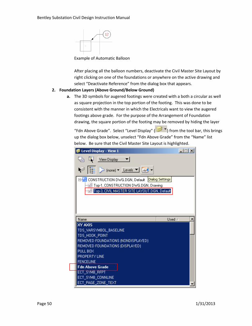
2. Foundation Layers (Above Ground/Below Ground)
a. The 3D symbols for augered footings were created with a both a circular as well
as square projection in the top portion of the footing. This was done to be
consistent with the manner in which the Electricals want to view the augered
footings above grade. For the purpose of the Arrangement of Foundation
drawing, the square portion of the footing may be removed by hiding the layer
“Fdn Above Grade”. Select “Level Display” ( ) from the tool bar, this brings
up the dialog box below, unselect “Fdn Above Grade” from the “Name” list
below. Be sure that the Civil Master Site Layout is highlighted.
Bentley Substation Civil Design Instruction Manual
Page 51 1/31/2013
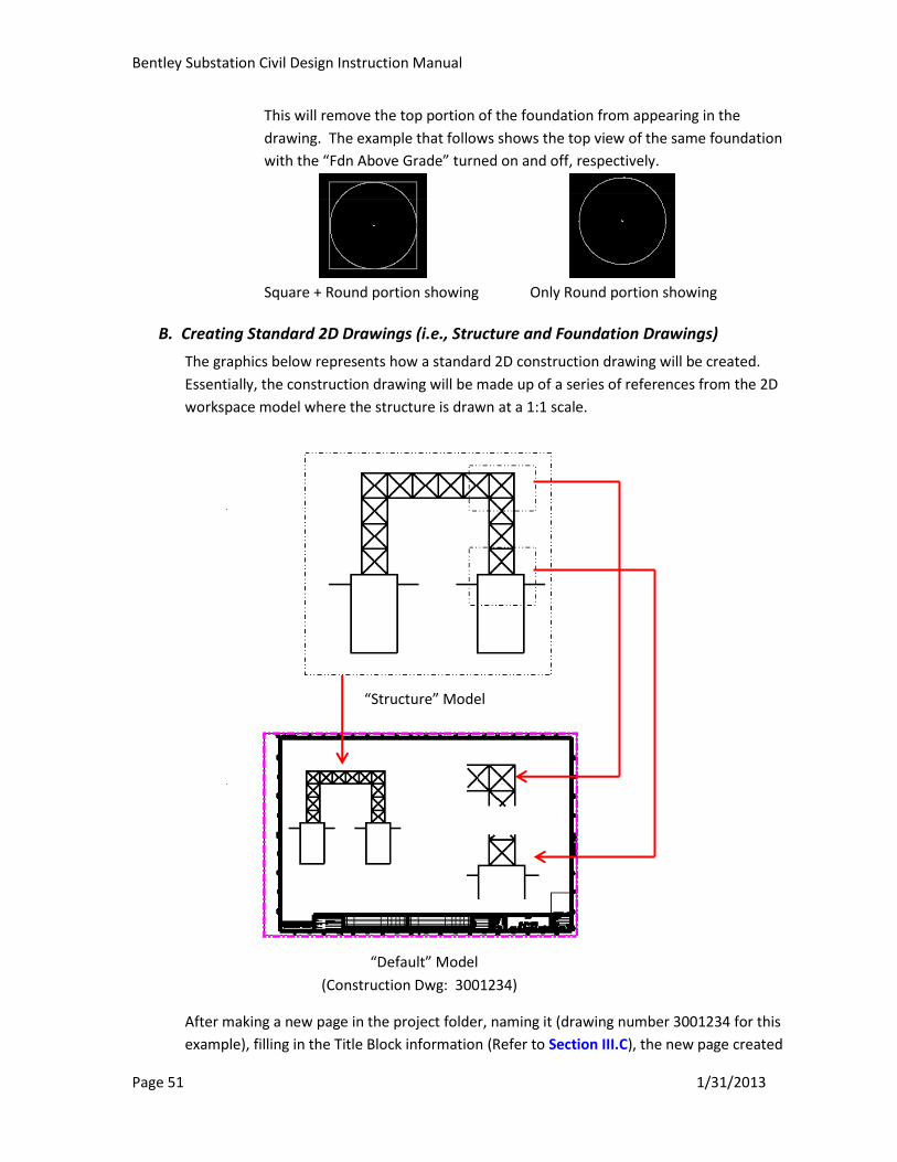
This will remove the top portion of the foundation from appearing in the
drawing. The example that follows shows the top view of the same foundation
with the “Fdn Above Grade” turned on and off, respectively.
Square + Round portion showing Only Round portion showing
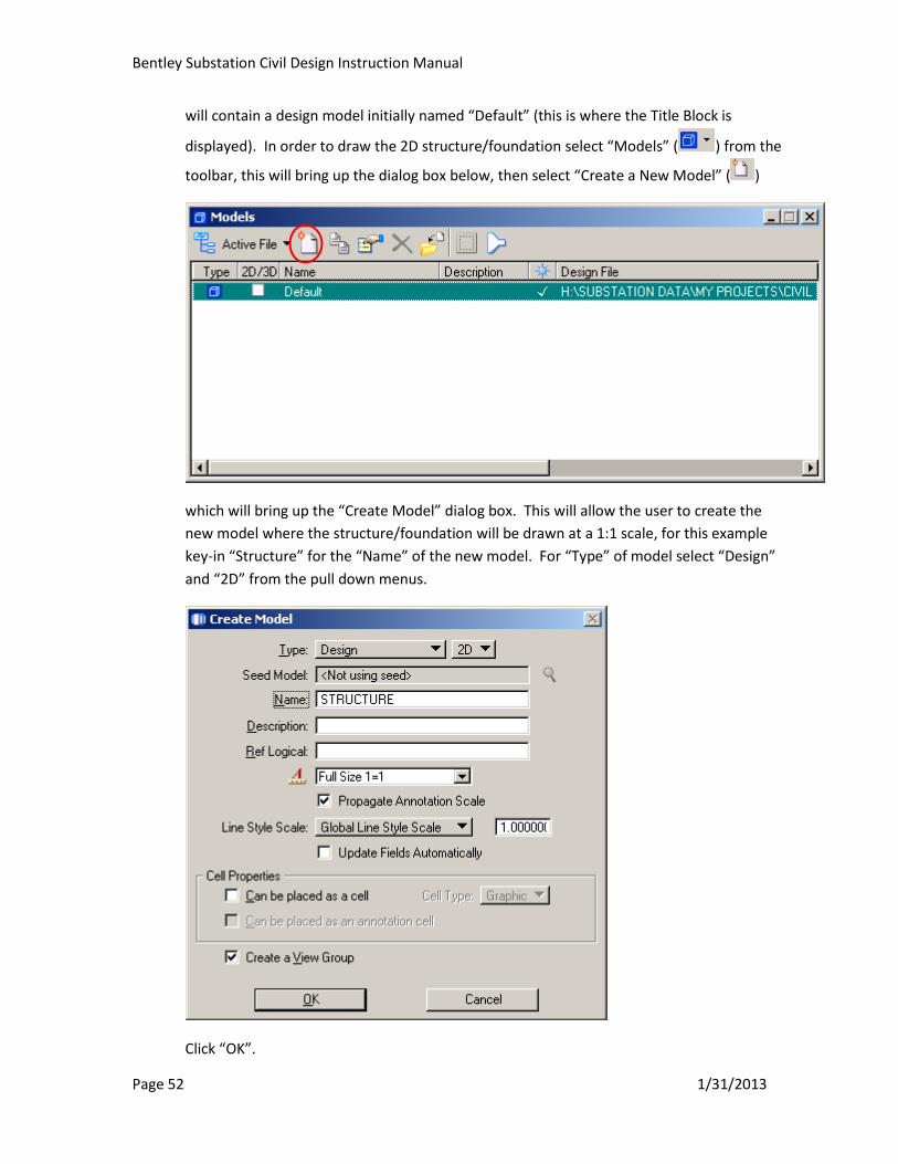
B. Creating Standard 2D Drawings (i.e., Structure and Foundation Drawings)
The graphics below represents how a standard 2D construction drawing will be created.
Essentially, the construction drawing will be made up of a series of references from the 2D
workspace model where the structure is drawn at a 1:1 scale.
After making a new page in the project folder, naming it (drawing number 3001234 for this
example), filling in the Title Block information (Refer to Section III.C), the new page created
“Structure” Model
“Default” Model
(Construction Dwg: 3001234)
Bentley Substation Civil Design Instruction Manual
Page 52 1/31/2013
will contain a design model initially named “Default” (this is where the Title Block is
displayed). In order to draw the 2D structure/foundation select “Models” ( ) from the
toolbar, this will bring up the dialog box below, then select “Create a New Model” ( )
which will bring up the “Create Model” dialog box. This will allow the user to create the
new model where the structure/foundation will be drawn at a 1:1 scale, for this example
key-in “Structure” for the “Name” of the new model. For “Type” of model select “Design”
and “2D” from the pull down menus.
Click “OK”.
Bentley Substation Civil Design Instruction Manual
Page 53 1/31/2013
This will place you into the newly created “Structure” model.
Once all the detail for the structure and foundation are drawn in this “Structure” model, the
user goes back to the “Default" model by double clicking on it in the “Models” dialog box.
Once back in the “Default” model, different portions of the structure/foundation can be
referenced from the “Structure” model. For each portion of the “Structure” model that is
referenced, it needs to be scaled and possibly clipped for final placement on the
construction drawing.
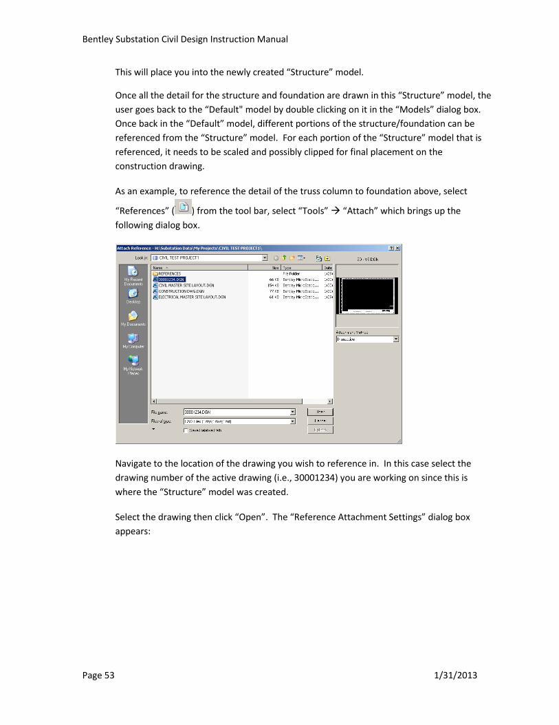
As an example, to reference the detail of the truss column to foundation above, select
“References” ( ) from the tool bar, select “Tools” “Attach” which brings up the
following dialog box.
Navigate to the location of the drawing you wish to reference in. In this case select the
drawing number of the active drawing (i.e., 30001234) you are working on since this is
where the “Structure” model was created.
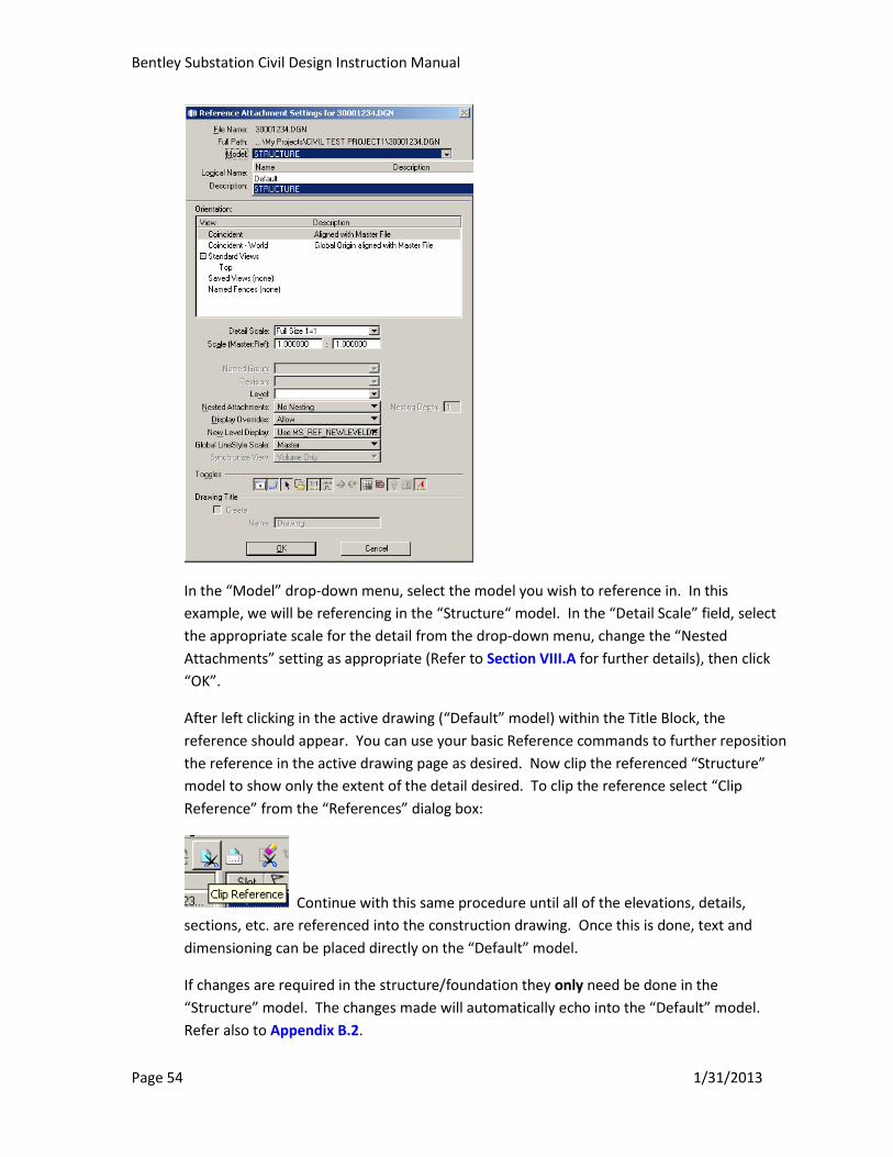
Select the drawing then click “Open”. The “Reference Attachment Settings” dialog box
appears:
Bentley Substation Civil Design Instruction Manual
Page 54 1/31/2013
In the “Model” drop-down menu, select the model you wish to reference in. In this
example, we will be referencing in the “Structure“ model. In the “Detail Scale” field, select
the appropriate scale for the detail from the drop-down menu, change the “Nested
Attachments” setting as appropriate (Refer to Section VIII.A for further details), then click
“OK”.
After left clicking in the active drawing (“Default” model) within the Title Block, the
reference should appear. You can use your basic Reference commands to further reposition
the reference in the active drawing page as desired. Now clip the referenced “Structure”
model to show only the extent of the detail desired. To clip the reference select “Clip
Reference” from the “References” dialog box:
Continue with this same procedure until all of the elevations, details,
sections, etc. are referenced into the construction drawing. Once this is done, text and
dimensioning can be placed directly on the “Default” model.
If changes are required in the structure/foundation they only need be done in the
“Structure” model. The changes made will automatically echo into the “Default” model.
Refer also to Appendix B.2.
Bentley Substation Civil Design Instruction Manual
Page 55 1/31/2013
C. Annotating Drawings
Plan, Detail, Notes, and Reference annotations will be added directly to the construction
drawing in a similar fashion as they were done in Microstation.
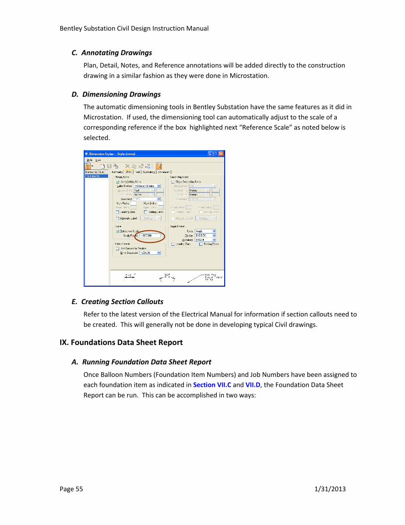
D. Dimensioning Drawings
The automatic dimensioning tools in Bentley Substation have the same features as it did in
Microstation. If used, the dimensioning tool can automatically adjust to the scale of a
corresponding reference if the box highlighted next “Reference Scale” as noted below is
selected.
E. Creating Section Callouts
Refer to the latest version of the Electrical Manual for information if section callouts need to
be created. This will generally not be done in developing typical Civil drawings.
IX. Foundations Data Sheet Report
A. Running Foundation Data Sheet Report
Once Balloon Numbers (Foundation Item Numbers) and Job Numbers have been assigned to
each foundation item as indicated in Section VII.C and VII.D, the Foundation Data Sheet
Report can be run. This can be accomplished in two ways:
Bentley Substation Civil Design Instruction Manual
Page 56 1/31/2013
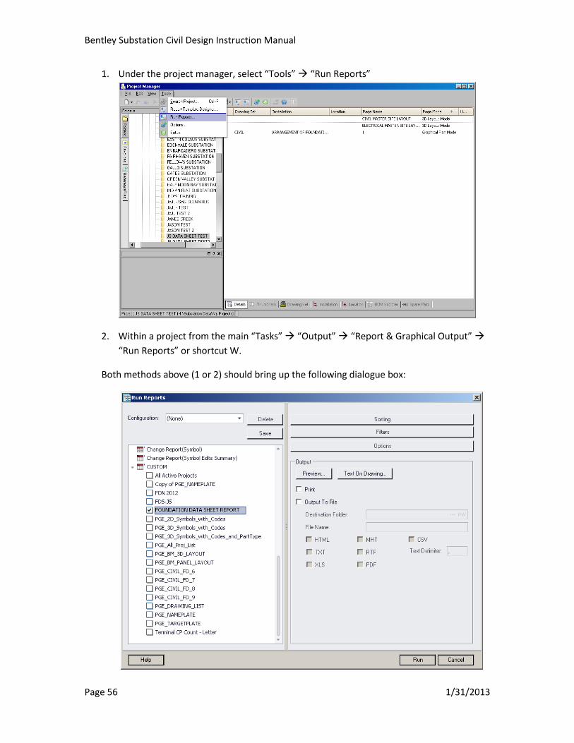
1. Under the project manager, select “Tools” “Run Reports”
2. Within a project from the main “Tasks” “Output” “Report & Graphical Output”
“Run Reports” or shortcut W.
Both methods above (1 or 2) should bring up the following dialogue box:
Bentley Substation Civil Design Instruction Manual
Page 57 1/31/2013
On the left panel, scroll down to the bottom and click to expand the “CUSTOM” report
template; then click on the box to check “FOUNDATION DATA SHEET REPORT”. In the
Output panel, click on “Preview…” to generate a preview of the selected report. If the data
is not correct (or nothing is shown) – you must apply filters to get the desired data. Close
the Preview and click on “Filters.”
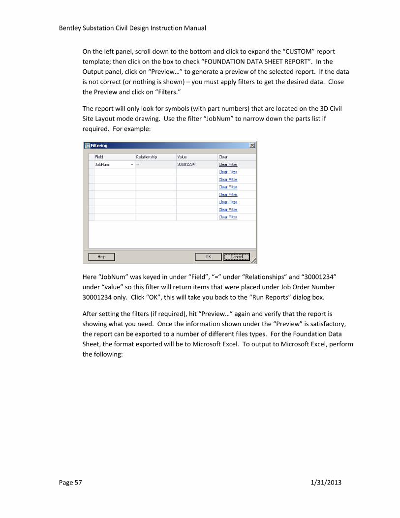
The report will only look for symbols (with part numbers) that are located on the 3D Civil
Site Layout mode drawing. Use the filter “JobNum” to narrow down the parts list if
required. For example:
Here “JobNum” was keyed in under “Field”, “=” under “Relationships” and “30001234”
under “value” so this filter will return items that were placed under Job Order Number
30001234 only. Click “OK”, this will take you back to the “Run Reports” dialog box.
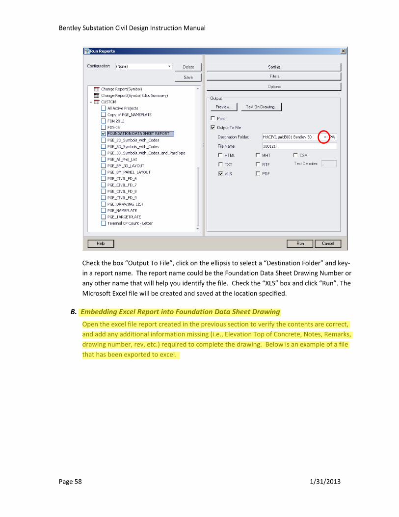
After setting the filters (if required), hit “Preview…” again and verify that the report is
showing what you need. Once the information shown under the “Preview” is satisfactory,
the report can be exported to a number of different files types. For the Foundation Data
Sheet, the format exported will be to Microsoft Excel. To output to Microsoft Excel, perform
the following:
Bentley Substation Civil Design Instruction Manual
Page 58 1/31/2013
Check the box “Output To File”, click on the ellipsis to select a “Destination Folder” and key-
in a report name. The report name could be the Foundation Data Sheet Drawing Number or
any other name that will help you identify the file. Check the “XLS” box and click “Run”. The
Microsoft Excel file will be created and saved at the location specified.
B. Embedding Excel Report into Foundation Data Sheet Drawing
Open the excel file report created in the previous section to verify the contents are correct,
and add any additional information missing (i.e., Elevation Top of Concrete, Notes, Remarks,
drawing number, rev, etc.) required to complete the drawing. Below is an example of a file
that has been exported to excel.
K. Chiu
Highlight
Bentley Substation Civil Design Instruction Manual
Page 59 1/31/2013
.
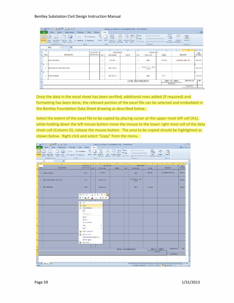
Once the data in the excel sheet has been verified, additional rows added (if required) and
formatting has been done, the relevant portion of the excel file can be selected and embedded in
the Bentley Foundation Data Sheet drawing as described below.
Select the extent of the excel file to be copied by placing curser at the upper most left cell (A1),
while holding down the left mouse button move the mouse to the lower right most cell of the data
sheet cell (Column O), release the mouse button. The area to be copied should be highlighted as
shown below. Right click and select “Copy” from the menu.
K. Chiu
Highlight
Bentley Substation Civil Design Instruction Manual
Page 60 1/31/2013
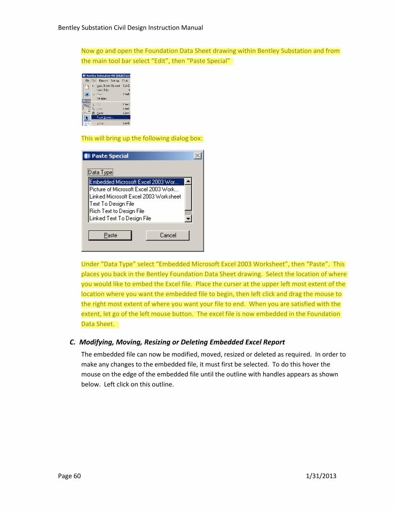
Now go and open the Foundation Data Sheet drawing within Bentley Substation and from
the main tool bar select “Edit”, then “Paste Special”
This will bring up the following dialog box:
Under “Data Type” select “Embedded Microsoft Excel 2003 Worksheet”, then “Paste”. This
places you back in the Bentley Foundation Data Sheet drawing. Select the location of where
you would like to embed the Excel file. Place the curser at the upper left most extent of the
location where you want the embedded file to begin, then left click and drag the mouse to
the right most extent of where you want your file to end. When you are satisfied with the
extent, let go of the left mouse button. The excel file is now embedded in the Foundation
Data Sheet.
C. Modifying, Moving, Resizing or Deleting Embedded Excel Report
The embedded file can now be modified, moved, resized or deleted as required. In order to
make any changes to the embedded file, it must first be selected. To do this hover the
mouse on the edge of the embedded file until the outline with handles appears as shown
below. Left click on this outline.
K. Chiu
Highlight
K. Chiu
Highlight
K. Chiu
Highlight

Bentley Substation Civil Design Instruction Manual
Page 61 1/31/2013
Once the outline is selected, double the left mouse button. This will launch the embedded
file into Excel again where modifications can be made to the data or the formatting. Once
the changes have been made, save the file and then exit from Excel. “File” ”Save”
”Close”. The changes made should now be reflected in the excel file embedded within in
the Foundation Data Sheet drawing
To resize the embedded excel file, hover over the file until the outline is selected as
described above and the handles are present. Left click and hold one of the handles on the
outline then drag the mouse to change the size to that desired. Let go of the mouse button
when the file is the correct size.
To delete the embedded excel file, hover over the file until the outline is selected as
described above and the handles are present. Select “Delete” on the keyboard or from the
main tool bar select “Edit” ”Cut”.
X. Generating Drawing List
To run a list of drawings for the project filtered by Installation, Location, and/or Drawing Set,
refer to Electrical Manual for further details.
XI. Plotting Construction Drawing(s)
Drawings can be printed individually similar to how they were printed in Microstation.
However, multiple drawings can also be plotted simultaneously.
A. Printing Full Size Drawings for Final Issue
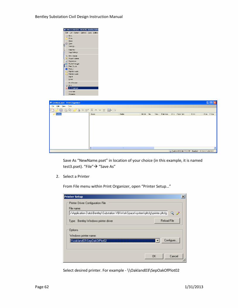
1. From File menu, open “Print Organizer”
Bentley Substation Civil Design Instruction Manual
Page 62 1/31/2013
Save As “NewName.pset” in location of your choice (in this example, it is named
test3.pset). “File” “Save As”
2. Select a Printer
From File menu within Print Organizer, open “Printer Setup…”
Select desired printer. For example - \\Oakland03\SepOakOfPlot02

Bentley Substation Civil Design Instruction Manual
Page 63 1/31/2013
Click “OK”.
3. Add Drawings to Print Set
Click “Add Files to Set” button
Note: If the “Select Files” dialog does not appear immediately, and instead the
“CreatePrint Definitions” box appears, click “Add”, on the “Select Files” click
“Cancel”.
Navigate to the correct folder where the drawings are loacted. Select files to be
added to print set. Hold down “CTRL” or “SHIFT” to select multiple drawings.
Click “Done”.
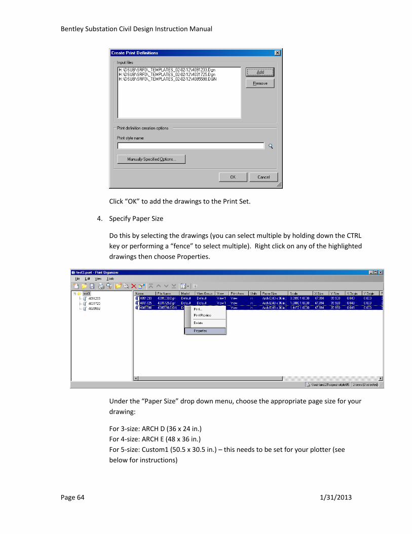
Bentley Substation Civil Design Instruction Manual
Page 64 1/31/2013
Click “OK” to add the drawings to the Print Set.
4. Specify Paper Size
Do this by selecting the drawings (you can select multiple by holding down the CTRL
key or performing a “fence” to select multiple). Right click on any of the highlighted
drawings then choose Properties.
Under the “Paper Size” drop down menu, choose the appropriate page size for your
drawing:
For 3-size: ARCH D (36 x 24 in.)
For 4-size: ARCH E (48 x 36 in.)
For 5-size: Custom1 (50.5 x 30.5 in.) – this needs to be set for your plotter (see
below for instructions)
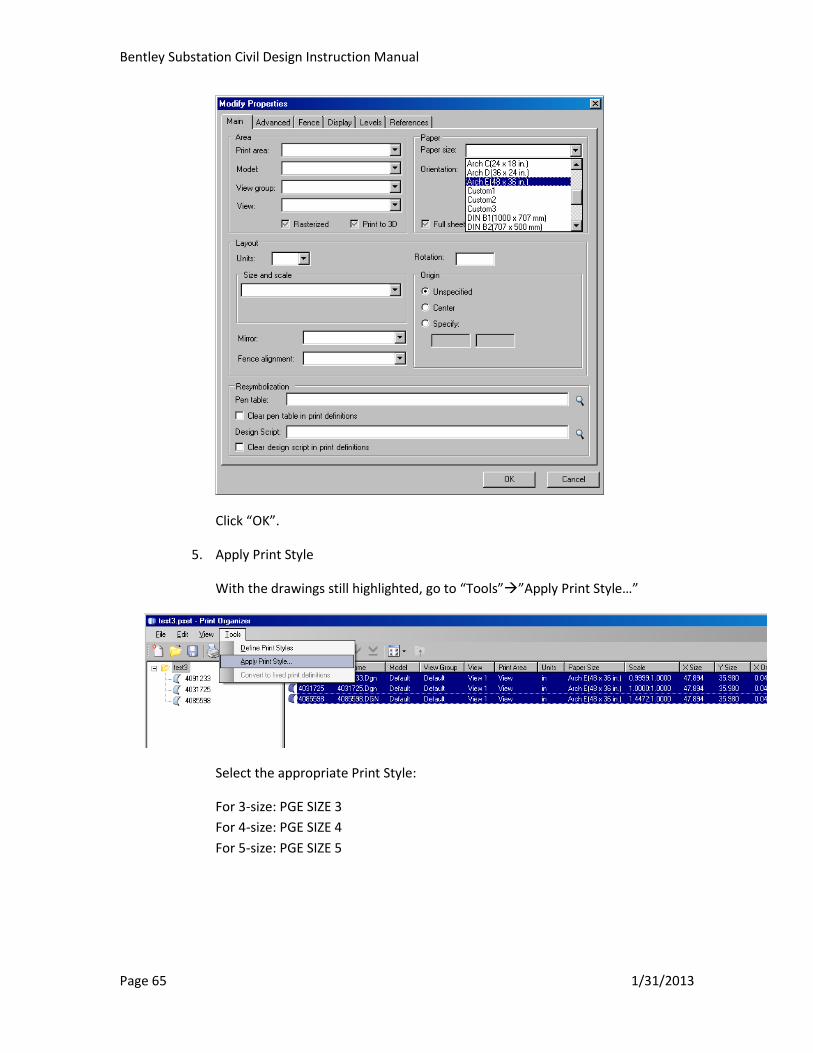
Bentley Substation Civil Design Instruction Manual
Page 65 1/31/2013
Click “OK”.
5. Apply Print Style
With the drawings still highlighted, go to “Tools””Apply Print Style…”
Select the appropriate Print Style:
For 3-size: PGE SIZE 3
For 4-size: PGE SIZE 4
For 5-size: PGE SIZE 5
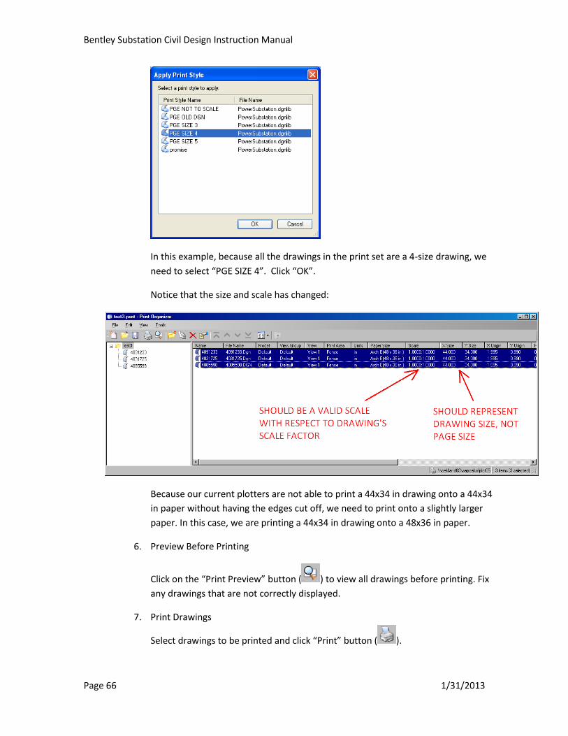
Bentley Substation Civil Design Instruction Manual
Page 66 1/31/2013
In this example, because all the drawings in the print set are a 4-size drawing, we
need to select “PGE SIZE 4”. Click “OK”.
Notice that the size and scale has changed:
Because our current plotters are not able to print a 44x34 in drawing onto a 44x34
in paper without having the edges cut off, we need to print onto a slightly larger
paper. In this case, we are printing a 44x34 in drawing onto a 48x36 in paper.
6. Preview Before Printing
Click on the “Print Preview” button ( ) to view all drawings before printing. Fix
any drawings that are not correctly displayed.
7. Print Drawings
Select drawings to be printed and click “Print” button ( ).
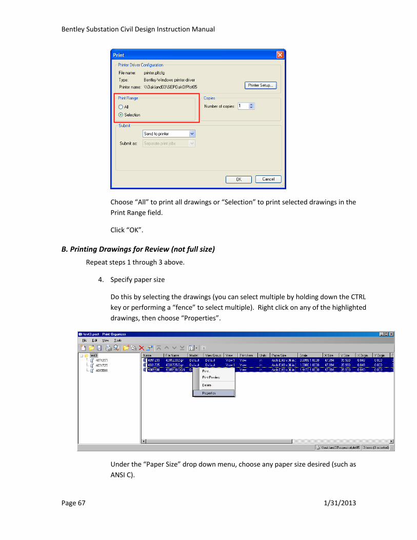
Bentley Substation Civil Design Instruction Manual
Page 67 1/31/2013
Choose “All” to print all drawings or “Selection” to print selected drawings in the
Print Range field.
Click “OK”.
B. Printing Drawings for Review (not full size)
Repeat steps 1 through 3 above.
4. Specify paper size
Do this by selecting the drawings (you can select multiple by holding down the CTRL
key or performing a “fence” to select multiple). Right click on any of the highlighted
drawings, then choose “Properties”.
Under the “Paper Size” drop down menu, choose any paper size desired (such as
ANSI C).
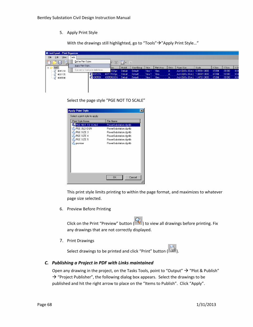
Bentley Substation Civil Design Instruction Manual
Page 68 1/31/2013
5. Apply Print Style
With the drawings still highlighted, go to “Tools””Apply Print Style…”
Select the page style “PGE NOT TO SCALE”
This print style limits printing to within the page format, and maximizes to whatever
page size selected.
6. Preview Before Printing
Click on the Print “Preview” button ( ) to view all drawings before printing. Fix
any drawings that are not correctly displayed.
7. Print Drawings
Select drawings to be printed and click “Print” button ( ).
C. Publishing a Project in PDF with Links maintained
Open any drawing in the project, on the Tasks Tools, point to “Output” “Plot & Publish”
“Project Publisher”, the following dialog box appears. Select the drawings to be
published and hit the right arrow to place on the “Items to Publish”. Click “Apply”.
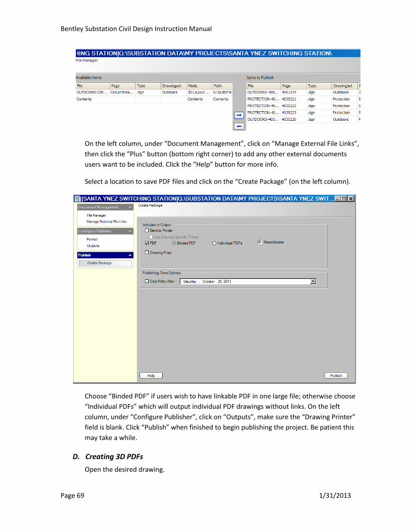
Bentley Substation Civil Design Instruction Manual
Page 69 1/31/2013
On the left column, under “Document Management”, click on “Manage External File Links”,
then click the “Plus” button (bottom right corner) to add any other external documents
users want to be included. Click the “Help” button for more info.
Select a location to save PDF files and click on the “Create Package” (on the left column).
Choose “Binded PDF” if users wish to have linkable PDF in one large file; otherwise choose
“Individual PDFs” which will output individual PDF drawings without links. On the left
column, under “Configure Publisher”, click on “Outputs”, make sure the “Drawing Printer”
field is blank. Click “Publish” when finished to begin publishing the project. Be patient this
may take a while.
D. Creating 3D PDFs
Open the desired drawing.
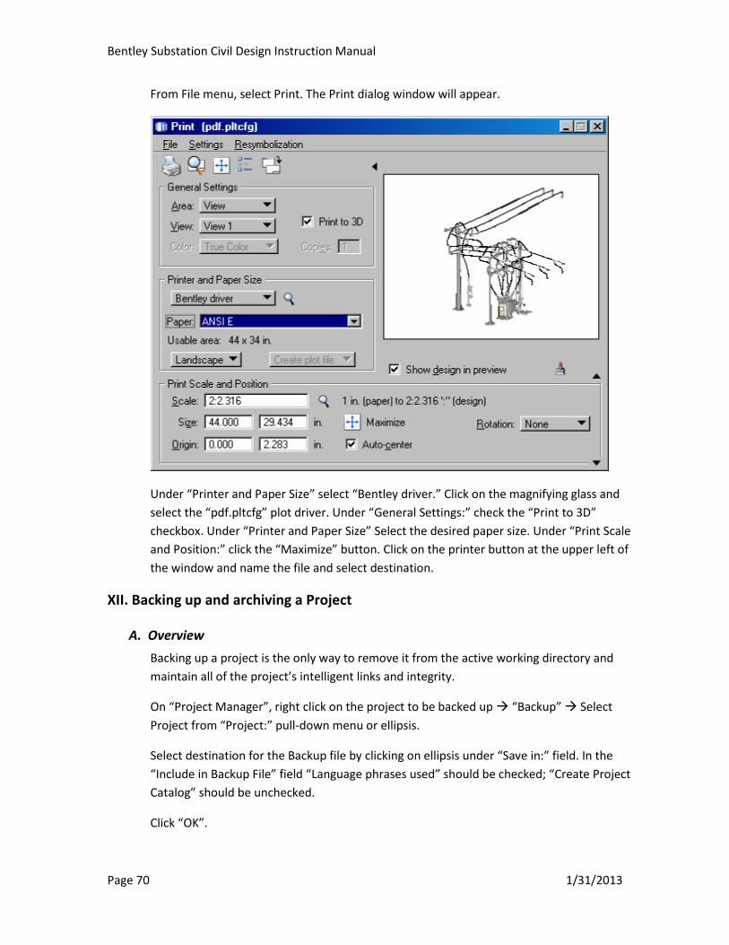
Bentley Substation Civil Design Instruction Manual
Page 70 1/31/2013
From File menu, select Print. The Print dialog window will appear.
Under “Printer and Paper Size” select “Bentley driver.” Click on the magnifying glass and
select the “pdf.pltcfg” plot driver. Under “General Settings:” check the “Print to 3D”
checkbox. Under “Printer and Paper Size” Select the desired paper size. Under “Print Scale
and Position:” click the “Maximize” button. Click on the printer button at the upper left of
the window and name the file and select destination.
XII. Backing up and archiving a Project
A. Overview
Backing up a project is the only way to remove it from the active working directory and
maintain all of the project’s intelligent links and integrity.
On “Project Manager”, right click on the project to be backed up “Backup” Select
Project from “Project:” pull-down menu or ellipsis.
Select destination for the Backup file by clicking on ellipsis under “Save in:” field. In the
“Include in Backup File” field “Language phrases used” should be checked; “Create Project
Catalog” should be unchecked.
Click “OK”.

Bentley Substation Civil Design Instruction Manual
Page 71 1/31/2013
The project backup file can be stored your C:\Data folder; however, it needs to be restored
before users can work on it. Refer to Section III.A for project restoration instructions.
B. Interim Mandatory Backup for Data Retention
***Important: these steps are required to be performed at least once a day to help
prevent substantial data loss***
Create the Bentley Substation Backup folder on your C:\Data folder as follows:
Right click on the “Start” menu “Explore” then navigate to C:\Data
Point to the C:\Data folder, right click “New” “New Folder” and Key-in Bentley
Substation Backup
Before closing Bentley Substation or at the end of the day, follow Section XII.A above to
backup your active project to the “Bentley Substation Backup” folder on the C:\Data folder.
This C:\Data folder is backed up regularly by IT.
We recommend a minimum of 3-day’s worth of backup data per project. Only the project
team lead is responsible for backing up the project he/she is responsible for; and each
project needs to be backed up by only one person. Typically the Electrical will perform the
backup for the project. However, this should be verified when starting a project. If the
project is Civil only, then the backup must be done by Civil.

Bentley Substation Civil Design Instruction Manual
Page 72 1/31/2013
C. Archiving a Project upon Completion
Pending Projectwise implementation, once a project has been completed, issued, and
incorporated, please back it up and inform one the project librarians below to have him/her
place your backup project to H:\Substation Data\Substation_LIB\Backup
The following individuals are identified as the librarians:
Civil: Alex Chung
Electrical: Kwan Chan, Anthony Chueng, Joe Leong, Anna Lewis, Rosencruz Sumera

Bentley Substation Civil Design Instruction Manual
Page 73 1/31/2013
Appendix A. Quick Guide
To be developed
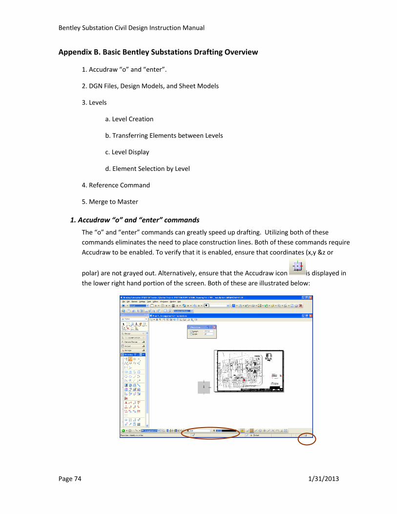
Bentley Substation Civil Design Instruction Manual
Page 74 1/31/2013
Appendix B. Basic Bentley Substations Drafting Overview
1. Accudraw “o” and “enter”.
2. DGN Files, Design Models, and Sheet Models
3. Levels
a. Level Creation
b. Transferring Elements between Levels
c. Level Display
d. Element Selection by Level
4. Reference Command
5. Merge to Master
1. Accudraw “o” and “enter” commands
The “o” and “enter” commands can greatly speed up drafting. Utilizing both of these
commands eliminates the need to place construction lines. Both of these commands require
Accudraw to be enabled. To verify that it is enabled, ensure that coordinates (x,y &z or
polar) are not grayed out. Alternatively, ensure that the Accudraw icon is displayed in
the lower right hand portion of the screen. Both of these are illustrated below:
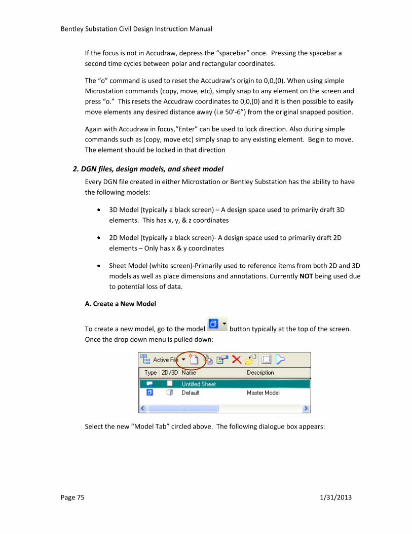
Bentley Substation Civil Design Instruction Manual
Page 75 1/31/2013
If the focus is not in Accudraw, depress the “spacebar” once. Pressing the spacebar a
second time cycles between polar and rectangular coordinates.
The “o” command is used to reset the Accudraw’s origin to 0,0,(0). When using simple
Microstation commands (copy, move, etc), simply snap to any element on the screen and
press “o.” This resets the Accudraw coordinates to 0,0,(0) and it is then possible to easily
move elements any desired distance away (i.e 50’-6”) from the original snapped position.
Again with Accudraw in focus,“Enter” can be used to lock direction. Also during simple
commands such as (copy, move etc) simply snap to any existing element. Begin to move.
The element should be locked in that direction
2. DGN files, design models, and sheet model
Every DGN file created in either Microstation or Bentley Substation has the ability to have
the following models:
3D Model (typically a black screen) – A design space used to primarily draft 3D
elements. This has x, y, & z coordinates
2D Model (typically a black screen)- A design space used to primarily draft 2D
elements – Only has x & y coordinates
Sheet Model (white screen)-Primarily used to reference items from both 2D and 3D
models as well as place dimensions and annotations. Currently NOT being used due
to potential loss of data.
A. Create a New Model
To create a new model, go to the model button typically at the top of the screen.
Once the drop down menu is pulled down:
Select the new “Model Tab” circled above. The following dialogue box appears:
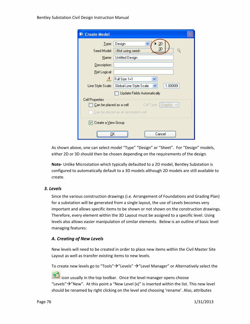
Bentley Substation Civil Design Instruction Manual
Page 76 1/31/2013
As shown above, one can select model “Type” “Design” or “Sheet”. For “Design” models,
either 2D or 3D should then be chosen depending on the requirements of the design.
Note- Unlike Microstation which typically defaulted to a 2D model, Bentley Substation is
configured to automatically default to a 3D models although 2D models are still available to
create.
3. Levels
Since the various construction drawings (i.e. Arrangement of Foundations and Grading Plan)
for a substation will be generated from a single layout, the use of Levels becomes very
important and allows specific items to be shown or not shown on the construction drawings.
Therefore, every element within the 3D Layout must be assigned to a specific level. Using
levels also allows easier manipulation of similar elements. Below is an outline of basic level
managing features:
A. Creating of New Levels
New levels will need to be created in order to place new items within the Civil Master Site
Layout as well as transfer existing items to new levels.
To create new levels go to “Tools””Levels” ”Level Manager” or Alternatively select the
icon usually in the top toolbar. Once the level manager opens choose
“Levels””New”. At this point a “New Level (x)” is inserted within the list. This new level
should be renamed by right clicking on the level and choosing ‘rename’. Also, attributes
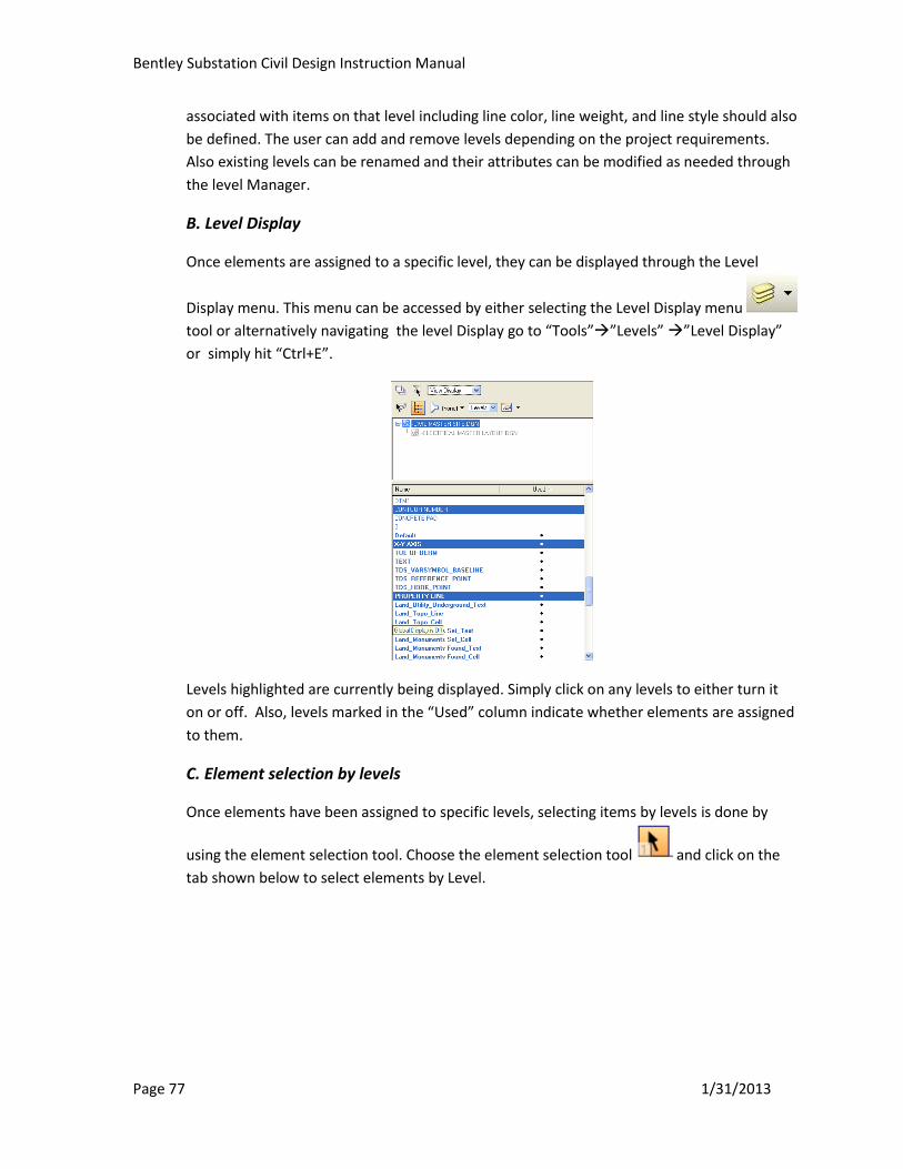
Bentley Substation Civil Design Instruction Manual
Page 77 1/31/2013
associated with items on that level including line color, line weight, and line style should also
be defined. The user can add and remove levels depending on the project requirements.
Also existing levels can be renamed and their attributes can be modified as needed through
the level Manager.
B. Level Display
Once elements are assigned to a specific level, they can be displayed through the Level
Display menu. This menu can be accessed by either selecting the Level Display menu
tool or alternatively navigating the level Display go to “Tools””Levels” ”Level Display”
or simply hit “Ctrl+E”.
Levels highlighted are currently being displayed. Simply click on any levels to either turn it
on or off. Also, levels marked in the “Used” column indicate whether elements are assigned
to them.
C. Element selection by levels
Once elements have been assigned to specific levels, selecting items by levels is done by
using the element selection tool. Choose the element selection tool and click on the
tab shown below to select elements by Level.

Bentley Substation Civil Design Instruction Manual
Page 78 1/31/2013
Elements can also be selected by other attributes (i.e. color, line style, line weight, etc) in a
similar manner simply by selecting a different tab within the element selection tool.
A. Transferring elements to a specific level
Ensure that the “Attributes” toolbar shown below is displayed. This toolbar is typically
located at the top of the Bentley Substation.
If it does not appear select “Tools”and select “Attributes”
To transfer elements to a specific level, select the elements using the element selection tool
then pull down the drop down menu within the “Attributes”toolbar (shown as “Default”
above) and select the appropriate destination level for the elements.

Bentley Substation Civil Design Instruction Manual
Page 79 1/31/2013
The elements should now have been transferred to the desired level.
Tip -To verify the correct elements were correctly transferred, select the destination Level
by using the element selection tool and ensure the elements transferred to that level are
selected.
4. Reference Command
Any drawing can be shown as a reference within another drawing. For example, the
Electrical Master Layout Site can be referenced into the Civil Master Site Layout to ensure
the location of the foundations correctly match their associated structure.
To reference in a drawing select the “Reference” command “Attach”, then navigate to
the folder containing the file to be referenced. If the file being referenced is located within
the same substation project, the files are typically found in H:\Substation Data\My
Projects\”Substation Name”
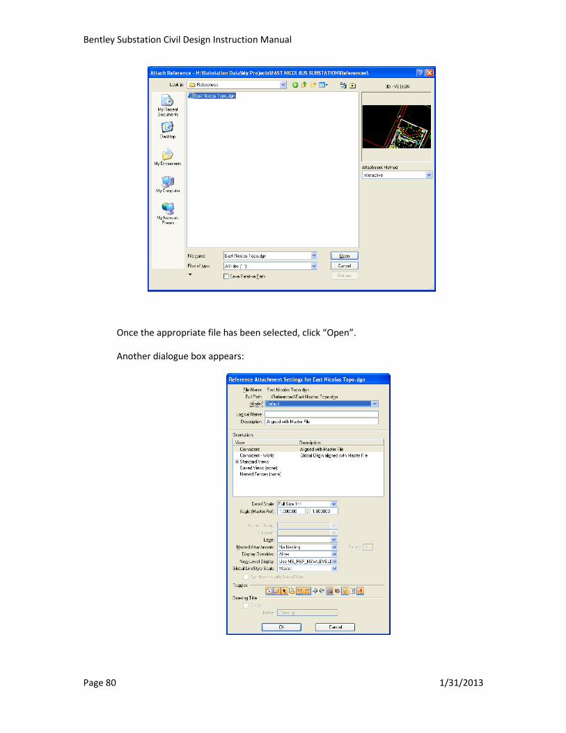
Bentley Substation Civil Design Instruction Manual
Page 80 1/31/2013
Once the appropriate file has been selected, click “Open”.
Another dialogue box appears:

Bentley Substation Civil Design Instruction Manual
Page 81 1/31/2013
Choose the appropriate model within the design files to be referenced (i.e. 2D or 3D). In
Bentley Substation, it will typically default to a 3D model.
Detail Scale: For most referencing this should be set to Full Size 1=1.
Nested Attachments: This determines how many of files referenced into the file being
referenced will show up in the destination file. For example, if set at “0” or “No Nesting”,
only the referenced file itself will be appear in the destination file. If set to 1, any file
referenced into the reference file will also be referenced into the destination file, and so on.
Toggles: Among the various toggles, the “Display Reference” toggle is used to turns on
and off the display of the selected reference.
5. Merge to Master Command
Any file that is referenced into another file can be incorporated into that file using the
“Merge to Master” command. This feature severs the tie to the source reference file and
elements currently displayed to become part of the destination file. This feature will be used
to bring exterior files like Topographical drawings and existing drawings into Bentley
Substation. Prior to using the merge command, the files should already be referenced into
the destination file. At this point, the file should be “Merged into Master” according to the
following steps:
Under the “Reference” command, Select the referenced drawing currently shown in the
referenced in from the list”Tools””Merge into Master”.
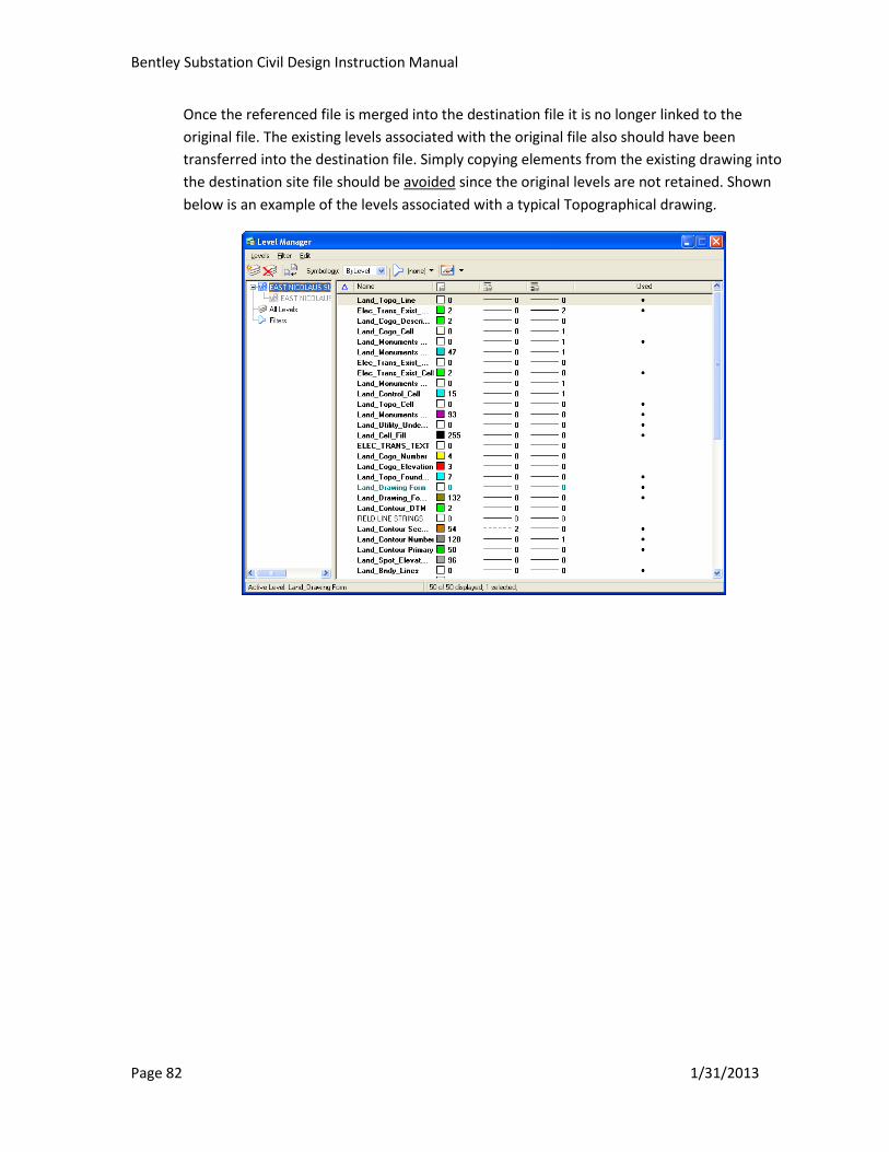
Bentley Substation Civil Design Instruction Manual
Page 82 1/31/2013
Once the referenced file is merged into the destination file it is no longer linked to the
original file. The existing levels associated with the original file also should have been
transferred into the destination file. Simply copying elements from the existing drawing into
the destination site file should be avoided since the original levels are not retained. Shown
below is an example of the levels associated with a typical Topographical drawing.
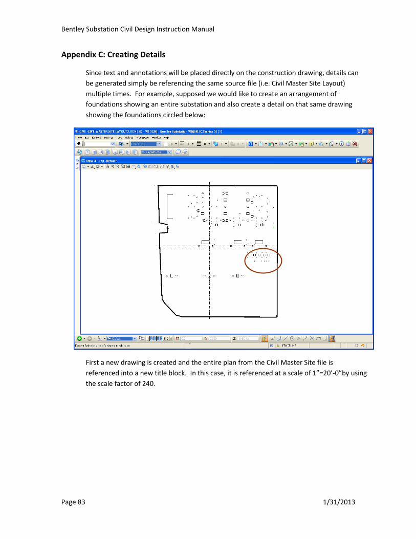
Bentley Substation Civil Design Instruction Manual
Page 83 1/31/2013
Appendix C: Creating Details
Since text and annotations will be placed directly on the construction drawing, details can
be generated simply be referencing the same source file (i.e. Civil Master Site Layout)
multiple times. For example, supposed we would like to create an arrangement of
foundations showing an entire substation and also create a detail on that same drawing
showing the foundations circled below:
First a new drawing is created and the entire plan from the Civil Master Site file is
referenced into a new title block. In this case, it is referenced at a scale of 1”=20’-0”by using
the scale factor of 240.
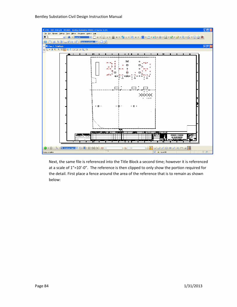
Bentley Substation Civil Design Instruction Manual
Page 84 1/31/2013
Next, the same file is referenced into the Title Block a second time; however it is referenced
at a scale of 1”=10’-0”. The reference is then clipped to only show the portion required for
the detail. First place a fence around the area of the reference that is to remain as shown
below:
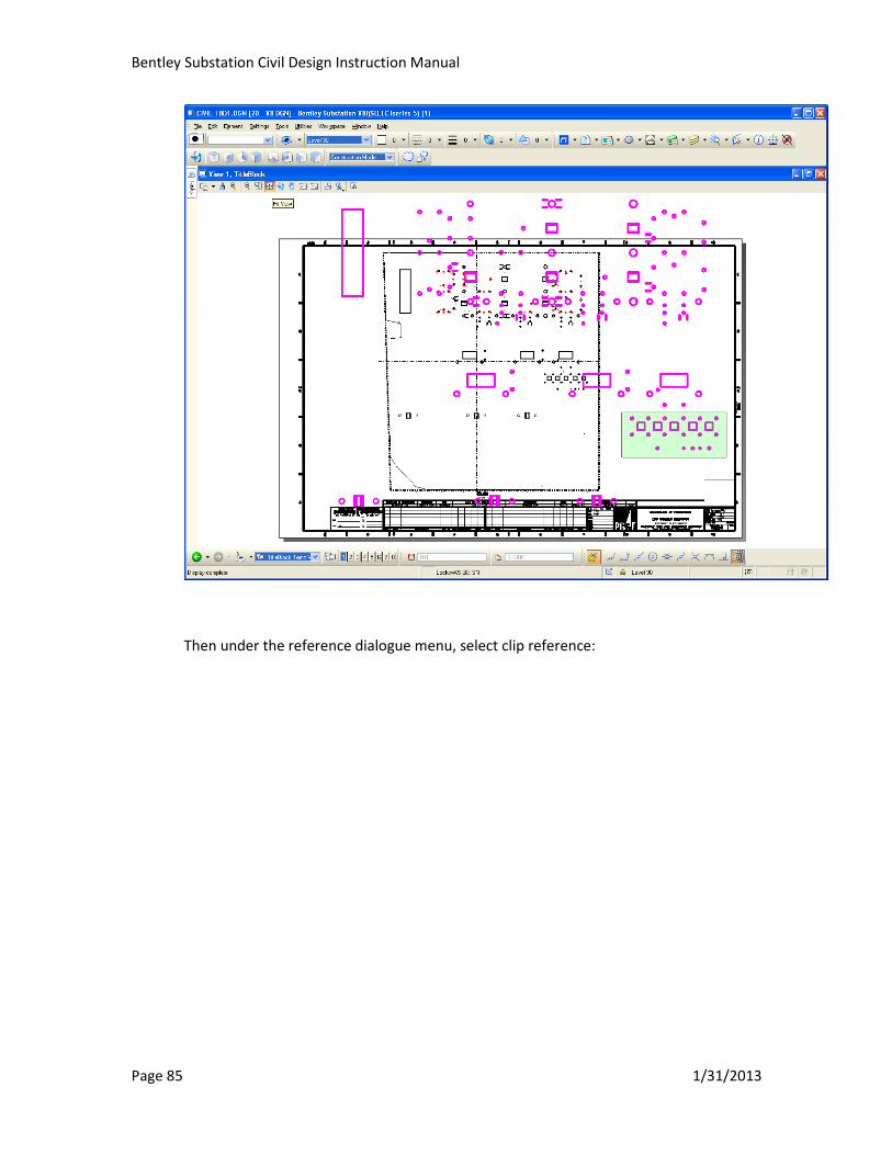
Bentley Substation Civil Design Instruction Manual
Page 85 1/31/2013
Then under the reference dialogue menu, select clip reference:
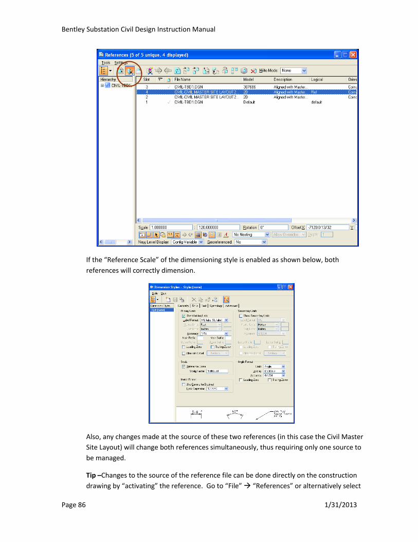
Bentley Substation Civil Design Instruction Manual
Page 86 1/31/2013
If the “Reference Scale” of the dimensioning style is enabled as shown below, both
references will correctly dimension.
Also, any changes made at the source of these two references (in this case the Civil Master
Site Layout) will change both references simultaneously, thus requiring only one source to
be managed.
Tip –Changes to the source of the reference file can be done directly on the construction
drawing by “activating” the reference. Go to “File” “References” or alternatively select
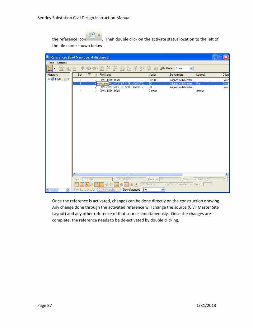
Bentley Substation Civil Design Instruction Manual
Page 87 1/31/2013
the reference icon . Then double click on the activate status location to the left of
the file name shown below:
Once the reference is activated, changes can be done directly on the construction drawing.
Any change done through the activated reference will change the source (Civil Master Site
Layout) and any other reference of that source simultaneously. Once the changes are
complete, the reference needs to be de-activated by double clicking.

Bentley Substation Civil Design Instruction Manual
Page 88 1/31/2013
Appendix D: Retaining Legacy Title Blocks and 0, 1, and 2 Drawings
To be developed