BENDING ACTUATORS BASED ON IONIC ELECTROACTIVE...
81
BENDING ACTUATORS BASED ON IONIC ELECTROACTIVE POLYMERS By SHAYAN MEHRAEEN Submitted to the Institute of Engineering and Natural Sciences in partial fulfillment of the requirements for the degree of Doctor of Philosophy Sabancı University April 2018
Transcript of BENDING ACTUATORS BASED ON IONIC ELECTROACTIVE...

BENDING ACTUATORS BASED ON IONIC
ELECTROACTIVE POLYMERS
By
SHAYAN MEHRAEEN
Submitted to the Institute of Engineering and Natural Sciences
in partial fulfillment of
the requirements for the degree of
Doctor of Philosophy
Sabancı University
April 2018

BENDING ACTUATORS BASED ON IONIC
ELECTROACTIVE POLYMERS
Approved by:
Prof. Dr. Selmiye Alkan Gürsel ……………………………
(Thesis Advisor)
Assoc. Prof. Dr. Gözde İnce ……………………………
(Jury member)
Assoc. Prof. Dr. Güllü Kızıltaş Şendur .……………………………
(Jury member)
Prof. Dr. Alimet Sema Özen .……………………………
(Jury member)
Assoc. Prof. Dr. Ebru Menşur Alkoy .……………………………
(Jury member)
DATE OF APPROVAL: 19 / 04 / 2018

© Shayan Mehraeen 2018
All Rights Reserved.

iv
Bending actuators based on ionic electroactive
polymers
Shayan Mehraeen
Ph.D. Dissertation, April 2018
Thesis Supervisor: Prof. Dr. Selmiye Alkan Gürsel
Co-advisors: Assoc. Prof. Dr. Fevzi Ç. Cebeci, Prof. Dr. Melih Papila
Keywords: polyaniline nanofiber, actuation stroke, bending actuator, gel electrolyte,
poly(vinylidene fluoride), poly(styrene sulfonic acid), PVDF-g-PSSA, IPMC, radiation-
induced graft polymerization
Abstract
In this thesis, two actuation systems based on two different conductive polymers were
designed, prepared and characterized. In the first part, polyaniline nanofibers were used
as main actuation component. Polyaniline nanofibers have shown promising electrical
and electrochemical properties which make them prominent candidates in the
development of smart systems employing sensors and actuators. Their electrochemical
actuation potential is demonstrated in this study. A trilayer composite actuator based on
polyaniline nanofibers was designed and fabricated. Cross-linked polyvinyl alcohol was
sandwiched between two polyaniline nanofibrous electrodes as ion-containing electrolyte
gel. First, electrochemical behavior of a single electrode was studied, showing reversible
redox peak pairs in 1 M HCl using a cyclic voltammetry technique. High aspect ratio
polyaniline nanofibers create a porous network which facilitates ion diffusion and thus
accelerates redox reactions. Bending displacement of the prepared trilayer actuator was
then tested and reported under an AC potential stimulation as low as 0.5 V in a variety of
frequencies from 50 to 1000 mHz, both inside 1 M HCl solution and in the air. The decay
of performance of the composite actuator in the air is investigated and it is reported that
tip displacement in a solution was stable and repeatable for 1000 s in all selected
frequencies.
v
In the second part of the thesis, a high performance ionic polymer-metal composite
actuator (IPMC) based on proton conductivity of poly(styrene sulfonic acid) was
fabricated using a simple and novel method. Poly(styrene sulfonic acid) (PSSA) as a well-
known hydrophilic proton conductive functional group was radiation grafted on
polyvinylidene fluoride (PVDF) at different graft levels. The material system is well
known for the proton exchange membranes of fuel cells, however, its IPMC application
is novel. Flexible, soft and porous membranes were prepared by simple solution casting
technique. Physical, mechanical, thermal and actuation properties of prepared membranes
were characterized and compared with Nafion®. The membrane with highest graft level
showed comparable ion exchange capacity and proton conductivity with that of Nafion
whereas its water uptake is near three-fold greater than Nafion. To make PVDF-g-PSSA
based IPMC actuators, Pt particles were deposited on both sides of the membranes using
electroless plating method. Actuation performance of the IPMC actuators under various
AC potentials and different frequencies were investigated. The results revealed that the
PVDF-g-PSSA membrane with highest graft level showed highest average bending strain
at 0.1 Hz and 4 V. The enhanced bending actuation behavior was attributed to porous
morphology and large water uptake of graft polymerized actuators. Compared with
traditional Nafion-based IPMC, our bending actuator is cheaper, and its preparation is fast
and simple. So, it can be a viable replacement candidate for the traditional Nafion in soft
actuator systems.

vi
İyonik elektroaktif polimer esaslı bükülme
eyleyicileri
Shayan Mehraeen
DoktoraTezi, Nisan 2018
Tez Danışmanı: Prof. Dr. Selmiye Alkan Gürsel
Ortak tez danışmanları: Doç. Dr. Fevzi Ç. Cebeci, Prof. Dr. Melih Papila
Anahtar Kelimeler: polianilin nanofiber, eyleyici hareketi, bükülme eyleyicileri, jel
elektrolit, poli(vinilidin florür), poli(stiren sülfonik asit), PVDF-g-PSSA, IPMC,
radyasyon başlatmalı aşılamalı polimerleşme
Özet
Bu doktora tezinde, iki farklı iletken polimer esaslı iki çeşit eyleyici sistemi tasarlanmış,
hazırlanmış ve karakterizasyonları gerçekleştirilmiştir. İlk kısımda, polianilin
nanofiberleri esas eyleyici bileşeni olarak kullanılmıştır. Polianilin nanofiberleri çok iyi
elektriksel ve elektrokimyasal özellikler gösterdiklerinden, özellikle sensor ve eyleyici
gibi akıllı sistemlerde kullanılmaa potansiyeli göstermektedirler. Bu çalışmada, polianilin
nanofiberlerin elektrokimyasal eyleyici olarak kullanımları gösterilmektedir. Bu amaç
için üç tabakadan oluşan polianilin esaslı kompozit eyleyiciler tasarlanmış ve üretilmiştir.
Çapraz bağlanmış poli (vinil alkol) iyon içeren elektrolit olarak kullanılmış ve polianilin
esaslı iki nanofiber elektrotlar arasına sandviç şeklinde sıkıştırılmıştır. İlk olarak, tekli
elektrotun elektrokimyasal davranışı çevrimsel voltametri yöntemi ile incelenmiş ve 1 M
HCl içinde tersinir redoks çifti gösterdiği saptanmıştır. Üretilen polianilin nanofiberleri,
yüksek en-boy oranına sahip olduğundan ve gözenekli bir yapı oluşturduklarından, iyon
difüzyonunu kolaylaştırmakta ve böylelikle redox tepkimelerin hızlı bir biçimde
gerçekleşmesi sağlanmaktadır. Ardıından, üretilen bu üç tabakalı eyleyicilerin bükülme
deplasmanları AC potansiyeli altında 0.5 V gibi düşük potansiyellerde ve 50-1000 mHz

vii
frekans aralığında, hem 1 M HCl içinde hem de havada incelenmiştir. Ayrıca, kompozit
yapılı bu eyleyicilerin havadaki bozulma performansları incelenmiş ve seçilen frekans
aralığında 1000 s boyunca kararlı ve tekrarlanabilir olduğu da görülmüştür.
Tezin ikinci bölümünde ise, poli(stiren sülfonik asit) esaslı yüksek performanslı iyonik
metal polimer kompozit (IPMC) eyleyiciler oldukça kolay ve yenilikçi bir yöntemle
üretilmiştir. Bu amaç için, oldukça iyi bilinen hidrofilik proton iletken poli(stiren sülfonik
asit (PSSA) fonksiyonel grupları radyasyonla aşılama yöntemiyle poli(vinilidin florür
üzerine çeşitli aşılama derecelerinde aşılanmıştır. Bu şekilde radyasyonla aşılanmış
sistemler, yakıt pilleri için proton değişim membranları olarak yaygın olarak
kullanılmalaarına rağmen, bu tür proton ileten yapıların IPMC uygulamaları için
kullanılmaları oldkça yenilikçi bir yaklaşımdır. Esnek, yumuşak ve gözenekli
membranlar çözeltiden dökme yöntemiyle kolaylıkla üretlmiştir. Üretilen membranlaarın
fiziksel, mekanik, ısıl özellikleri ve eyleyici performansları incelenmiş ve benzer yapıdaki
ticari Nafion® membranlarıyla kıyaslamaları yapılmıştır. Üretilen radyasyonla aşılanmış
membranlardan yüksek aşılama derecesine sahip olan membran, ticari Nafion
membranlarıyla kıyaslanabilir bir iyon değişim kapasitesi ve proton ilekenliğe sahip
oldukları ve yaklaşık olarak üç kat daha fazla su alımına sahip oldukları görülmüştür.
PVDF-g-PSSA esaslı IPMC eyleyiciler, radyasyonla aşılanmış üstün özellikli bu
membranların iki tarafına, elektrokaplama yöntemiyle Pt nanoparçacıklarının
kaplanmasıyla üretilmişlerdir. Bu IPMC eyleyicilerinin, performansları farklı AC
potansiyellerinde ve çeşitli frekanslarda incelenmişlerdir. En yüksek aşılama derecesine
sahip membran ile hazırlanan IPMC’nin, 0.1 Hz ve 4 V’de en yüksek bükülme gerilimi
gösterdiği bulunmuştur. IPMC’lerin gözenekli yapısı ve yüksek miktarda su alımı
sayesinde, radyasyonla aşılanmış membran içeren eyleyicilerde üstün bükülme
performansı elde edilmiştir. Bu tez kapsamında geliştirilen eyleyiciler, geleneksel Nafion-
esaslı IPMC’lerle kıyaslandıklarında, ucuz olmakla kalmayıp, oldukça kolay üretim
yöntemi gibi bir diğer avantaja sahiptir. Bu sebeplerle, bu tez kapsamında geliştirilen
IPMC’ler yumuşak eylecilerde Nafion’un yerini alabilecek umut vadeden yepyeni
yapılardır.

viii
To my beloved wife, Soheila Ghofrani

ix
Acknowledgment
I would like to express my acknowledgments to all people who have helped and supported
me along my path to fulfilling this goal.
I would like to express my sincere gratitude and appreciation to my thesis advisor, Prof.
Dr. Selmiye Alkan Gürsel for persistent help and support not only by academic and
scientific means but also by taking care of my situation as an international student.
I would like to also gracefully appreciate my other thesis co-advisors, Assoc. Prof. Dr.
Fevzi Çakmak Cebeci and Prof. Dr. Melih Papila for devoting their time and resources to
support and enhance my work and helping me with reviewing and commenting on my
work.
I want to thank also all my friends and colleagues here at Sabancı University for creating
a friendly and hard-working environment. My best respect and appreciations go to my
best friends and coworkers Sajjad Ghobadi, Adnan Taşdemir, Dr. Ali Tufani, and Ali
Ansari for keeping the work atmosphere always cooperative and friendly. Your great help
and assistance during my Ph.D. course are appreciated.
Finally, I wish to express my deepest gratitude and appreciation to my wife and soul mate,
Soheila Ghofrani for persistent love, priceless support and endless encouragement during
my Ph.D. course, without her sacrifice and self-devotion I would not be able to fulfill this
goal.
Shayan Mehraeen

x
TABLE OF CONTENTS
Abstract ............................................................................................................................ iv
Özet .................................................................................................................................. vi
Acknowledgment ............................................................................................................. ix
TABLE OF CONTENTS.................................................................................................. x
LIST OF FIGURES ........................................................................................................ xii
LIST OF TABLES ......................................................................................................... xiv
LIST OF SYMBOLS AND ABBREVIATIONS ........................................................... xv
1. Introduction ............................................................................................................... 1
1.1. Motivation .......................................................................................................... 1
1.2. Electrically conductive polymers ....................................................................... 1
1.3. Polyaniline; synthesis, characterizations, and properties ................................... 2
1.4. Polyaniline nanofibers; synthesis, properties and applications .......................... 6
1.5. Mechanism of actuation in PANI ....................................................................... 8
1.6. Designing an actuator using PANI nanofibers (NF) ........................................ 11
1.7. Ionic polymer metal composites (IPMC) ......................................................... 12
1.8. Manufacturing of IPMCs ................................................................................. 13
1.9. Mechanism of Actuation in IPMCs.................................................................. 15
1.10. Radiation grafted polymers .......................................................................... 16
1.10.1. Radiation source and dose ........................................................................ 17
1.10.2. Nature of base polymer ............................................................................. 18
1.10.3. Monomer concentration ............................................................................ 18
1.10.4. Graft temperature and medium ................................................................. 19
1.11. Designing an IPMC using PVDF-g-PSSA ................................................... 20
1.12. Contributions of this thesis ........................................................................... 22
2. Materials and Methods ............................................................................................ 23
2.1. Materials ........................................................................................................... 23
2.2. PANI nanofiber synthesis ................................................................................ 23
2.3. PANI emeraldine salt (ES) nanofiber electrode preparation............................ 24
2.4. PANI nanocomposite actuator preparation ...................................................... 24
2.5. Direct radiation induced grafting of poly(styrene sulfonic acid) on PVDF ..... 24
2.6. Preparation of IPMC actuator .......................................................................... 25
2.7. Characterizations methods ............................................................................... 26
2.7.1. Morphological characterization .................................................................... 26
2.7.2. Structural characterizations .......................................................................... 27
2.7.3. Electrical conductivity of PANI NF film ..................................................... 27
2.7.4. Surface charge characterization of PANI NF ............................................... 27

xi
2.7.5. Electrochemical characterizations ................................................................ 28
2.7.6. Mechanical characterization ......................................................................... 28
2.8. Physical properties of membranes; water uptake, Ion exchange capacity and
Degree of sulfonation .................................................................................................. 28
2.9. Proton conductivity of membranes .................................................................. 29
2.9.1. Thermal characterization .............................................................................. 30
2.9.2. Actuation test ................................................................................................ 30
2.9.2.1. Actuation measurements of PANI nanocomposite films .......................... 30
2.9.2.2. Actuation measurements of PVDF-g-PSSA films .................................... 31
3. Results and Discussion ............................................................................................ 32
3.1. PANI nanofibers characterizations .................................................................. 32
3.1.1. Morphology of PANI NFs ............................................................................ 32
3.2. Conductivity of PANI NFs .............................................................................. 32
3.3. Electroactivity of PANI NFs ............................................................................ 33
3.4. EQCM characterization of PANI NFs ............................................................. 33
3.5. Zeta potential, casting, and film forming behavior of PANI NFs .................... 34
3.5.1. Morphology characterizations ...................................................................... 36
3.5.2. Structural characterization of PANI NF film ............................................... 36
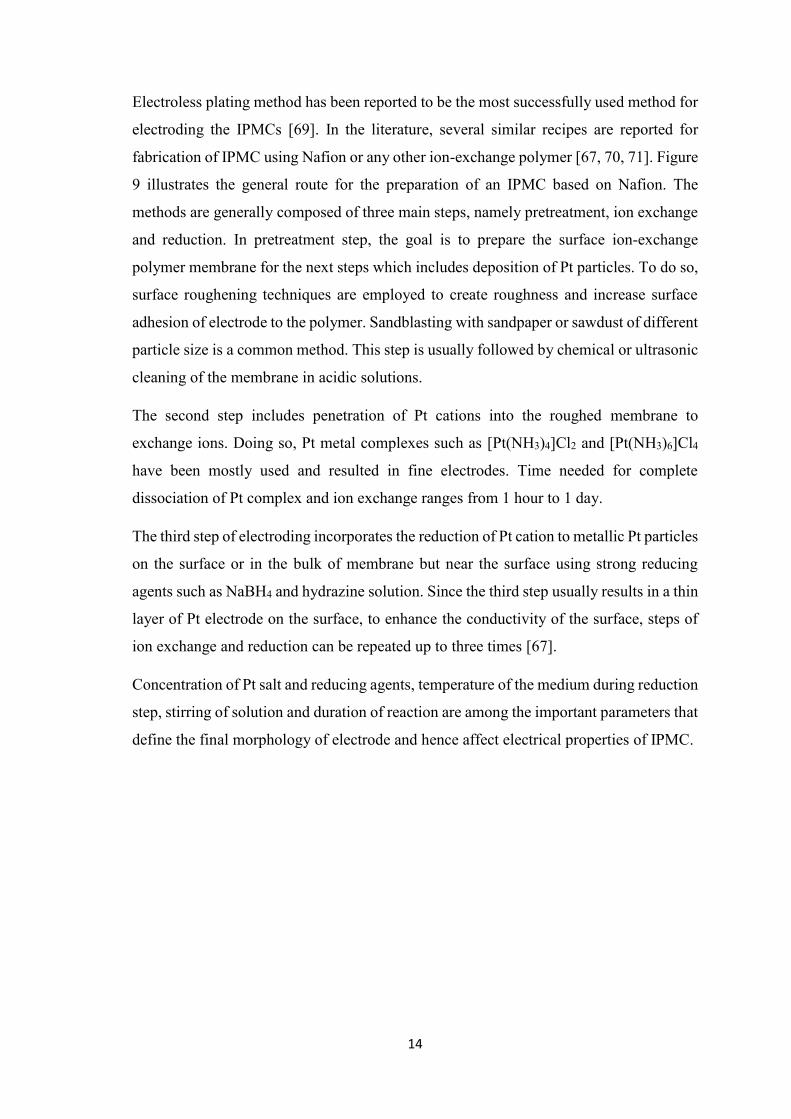
3.5.3. Electrical conductivity and electrochemical activity of PANI NF film ....... 37
3.5.4. Actuation behavior of PANI NF film actuator ............................................. 38
3.6. PVDF-g-PSSA actuator ................................................................................... 44
3.6.1. Graft level (GL) and degree of sulfonation (DOS) ...................................... 44
3.6.2. Structural characterization of PVDF-g-PSSA .............................................. 46
3.6.3. Morphology of PVDF-g-PSSA membranes ................................................. 48
3.6.4. Thermogravimetric characterization of PVDF-g-PSSA membrane ............. 50
3.6.5. Mechanical characterization of PVDF-g-PSSA membranes ........................ 50
3.6.6. Physical properties of PVDF-g-PSSA membranes ...................................... 51
3.6.7. Actuation properties of PVDF-g-PSSA IPMC actuators ............................. 52
4. Conclusions ............................................................................................................. 57
5. References ............................................................................................................... 59

xii
LIST OF FIGURES
Figure 1. Chemical (uncharged) structures of some typical conductive polymers. ..................... 2
Figure 2. Chemical structure of PANI in the base form. x=1 leucoemeraldine, x=0.5
emeraldine, x=0 pernigraniline. .................................................................................................... 3
Figure 3. Six chemical structures of PANI at different oxidation states pHs [8]. A- denotes acid
counterion. .................................................................................................................................... 3
Figure 4. Mechanism of oxidative polymerization of aniline by ammonium persulfate in acidic
solution. (a) initiation, (b) chain propagation, (c) termination by reduction of pernigraniline salt
to emeraldine salt. (HA denotes an acid with counter ion A-) [15]. .............................................. 5
Figure 5. Schematic of the so-called rapid mixing method for synthesis of PANI nanofibers. ... 7
Figure 6. Electrochemical oxidation states of PANI in salt and base forms. A- denotes acid
counter ion [8]. .............................................................................................................................. 9
Figure 7. A typical CV curve of PANI in HCl, depicting two sets of redox peaks. the
undertaking reactions are shown for each peak [36]. .................................................................. 10
Figure 8. The common chemical structure of Nafion. Na+ can be replaced with other cations
[67]. ............................................................................................................................................. 13
Figure 9. Fabrication method of an IPMC based on Nafion [69]. .............................................. 15
Figure 10. Mechanism of actuation in a typical IPMC. ............................................................. 16
Figure 11. Reaction schematic for radiation-induced graft copolymerization with different
methods [74]. .............................................................................................................................. 17
Figure 12. Schematic of home-made actuation set-up. .............................................................. 30
Figure 13. (a,b) SEM micrographs of as-synthesized PANI NFs at two magnifications. (c,d)
TEM micrographs of PANI NFs. The average aspect ratio of nanofibers was calculated as 60. 32
Figure 14. CV curve of PANI NFs in 1 M HCl at scan rate of 50 mV/s.................................... 33
Figure 15. Weight change of PANI NFs using EQCM technique performed simultaneously with
CV. .............................................................................................................................................. 34
Figure 16. Zeta potential of synthesized PANI NFs dispersed in pH=2.5 HCl solution. ........... 35
Figure 17. A flexible PANI NF film can be cast and peeled off when it is mixed with CL-PVA.
..................................................................................................................................................... 35
Figure 18. Morphological characterizations of prepared nanocomposite electrode; PANI ES
NF/CL-PVA. (a, b) SEM micrographs at two magnifications. .................................................. 36
Figure 19. FT-IR spectra of the nanocomposite electrode which is compared to the cross-linked
PVA (CL-PVA) and pristine PANI NF ES films. ....................................................................... 37
Figure 20. Cyclic voltammetry at three scan rates of 1, 5, 10 mV/s in 1M HCl. Gold coating
was applied on one side of the electrode. Inset graph illustrates corresponding oxidation peak
current vs. square root of scan rate which shows a linear behavior. ........................................... 38
Figure 21. (a) Schematic mechanism of actuation stroke of the prepared nanocomposite
bending actuator. (b) Cross section of the actuator without the gold electrode. The white color
on top of actuator film is reflection of light from nanocomposite actuator surface. (c, d)
Snapshots of the bending actuator strokes in the air. .................................................................. 40
Figure 22. Horizontal tip displacement of PANI ES NF/CL-PVA actuator under 1 M HCl
solution at various frequencies of; a) 50 mHz, b) 100 mHz, c) 500 mHz, d) 1000 mHz. ........... 41
Figure 23. Horizontal tip displacement of the PANI ES NF/CL-PVA actuator in the air at
various frequencies of: a) 50 mHz, b) 100 mHz, c) 500 mHz, d) 1000 mHz. ............................ 42
Figure 24. Total displacement of actuator tip in each cycle under 1 M HCl solution as a
function of time/cycle number at various of frequencies. ........................................................... 43
Figure 25. Total displacement of actuator tip in each cycle in the air as a function of time/cycle
number at various frequencies. ................................................................................................... 44
Figure 26. Schematic of graft polymerization method used in this work. ................................. 45

xiii
Figure 27. (a) Dependency of the graft level on sulfuric acid concentration as the main grafting
parameter. (b) Degree of sulfonation based on IEC for different grafted polymers. .................. 46
Figure 28. FT-IR spectra of PVDF-g-PSSA with different graft level compared with pristine
PVDF and Nafion(a). Magnified spectrum to illustrate details (b) and (c). ................................ 47
Figure 29. 1H NMR spectrum of grafted polymers compared with pristine PVDF. .................. 48
Figure 30. SEM micrographs of prepared G35 IPMC actuator before Pt electroless plating (a,b)
and after electroless plating (c,d). cross-section of plated G35 IPMC actuator (e). The red arrow
depicts EDS line scan along with cross section. (f) shows elemental line scan analysis curves for
Pt, S, and F along with the red arrow shown in (e). .................................................................... 49
Figure 31. Thermogravimetric curves of prepared graft copolymers as well as pristine PVDF. 50
Figure 32. Tensile modulus (a), and Tensile strength (b), of the prepared membrane in dry and
wet states, compared with Nafion. .............................................................................................. 51
Figure 33. Ion exchange capacity (a), water uptake (b), and proton conductivity (c) of prepared
membranes compared with Nafion. ............................................................................................ 52
Figure 34. Actuation of prepared IPMC actuators compared with Nafion under 4 V DC
potential. ...................................................................................................................................... 53
Figure 35. Average bending strain versus voltage for prepared IPMC actuators at (a) 0.1 Hz, (b)
0.5 Hz and (c) 1 Hz. (d) comparison of various frequencies for 35% graft IPMC actuator. ...... 54
Figure 36. Average bending strain versus frequency for prepared IPMC actuators for various
graft levels of (a) G19, (b) G29, (c) G35, (d) Nafion. (e) comparison of all prepared IPMC
actuators at highest potential of 4 V. ........................................................................................... 55
Figure 37. Bending strain as a function of time for selected conditions of (a) 4 V, 0.1 Hz. (b) 4
V, G35. (c) G35, 0.1 Hz. (d) Illustrates potential-time square-wave form which is used to
stimulate IPMC actuators. ........................................................................................................... 56
Figure 38. Successive snapshots of G35 IPMC actuator during actuation at 4 V DC potential in
the air. ......................................................................................................................................... 57

xiv
LIST OF TABLES
Table 1. FT-IR characteristic absorption bands of PANI NF and CL-PVA [64], [100], [101, 102].
..................................................................................................................................................... 37

xv
LIST OF SYMBOLS AND ABBREVIATIONS
°C Degree of Celsius
1D One dimensional
APS Ammonium persulfate
APS Ammonium persulfate
CL-PVA Cross-linked polyvinyl alcohol
cm Centimeter
CV Cyclic voltammetry
DIW Deionized water
DMSO Dimethyl sulfoxide
DOS Degree of sulfonation
DW Distilled water
EDS Energy-dispersive X-ray Spectroscopy
EQCM Electrochemical quartz crystal microbalance
ES Emeraldine salt
FE-SEM Field effect scanning electron microscope
FT-IR Fourier-transform infrared spectroscopy
g Gram
GA Glutaraldehyde
GL Graft level
H NMR Proton nuclear magnetic resonance
Hz Hertz
I Current
IEC Ion exchange capacity
IPMC Ionic polymer-metal composites
L Liter
l Electrode distance
LB Leucoemeraldine base
M Molar
min Minute

xvi
mL Milliliter
mm Millimeter
mV Millivolt
MW Molecular weight
NF Nanofibers
nm Nanometer
PANI Polyaniline
PANI NFs Polyaniline nanofibers
PB Pernigraniline base
p-Phenylenediamine p-PDA
PS Polystyrene
PSSA Poly(styrene sulfonic acid)
PSSS Poly(sodium styrene sulfonate)
Pt Platinum
PVA Polyvinyl alcohol
PVDF Poly(vinylidene fluoride)
PVDF-g-PSSA Poly(vinylidene fluoride) grafted poly(styrene sulfonic acid)
R Resistance
rpm Revolutions per minute
s Second
S Siemens
SSS Styrene-4-sulfonic acid sodium salt
t Thickness
T Temperature
TEM Transmission electron microscope
Tg Glass transition temperature
TGA Thermogravimetric analysis
V Voltage
wt. % Weight percent
WU Water uptake

xvii
δ Displacement
ε Strain
μ Micro
σ Conductivity

1
1. Introduction
1.1. Motivation
During the last decade, we have witnessed a rapid progress and development of smart
materials and structures, especially in the field of conductive polymers and soft actuators.
Thanks to pioneers in the field and numerous researchers working on this topic, a wide
range of actuator products are commercially available today. The science and technology
of soft actuators have reached the point that numerous comprehensive review articles and
handbooks are written in details of subtopics. Among all types of electroactive polymers
polypyrrole, poly(3,4-ethylenedioxythiophene) polystyrene sulfonate and polyaniline
have received much attraction for various applications due to ease of synthesis and higher
range of conductivity. However, the actuation potential of polyaniline nanofibers has not
been investigated yet.
On the other hand, ionic polymer-metal composite actuators have been considered as the
best candidate to be used in bioapplications due to their biocompatibility. However, some
important challenges are yet remained to be solved. Production of Nafion as the most
used and commercially available proton conductive polymer is still not cost effective and
simple. For this reason, researchers are looking for a replacement candidate to show good
mechanical and electrical properties of Nafion but with simpler and cheaper preparation
method.
In this thesis, two different actuation systems were designed, fabricated and investigated.
In the first system, polyaniline, an electronically conductive polymer was synthesized and
used to make bending actuator. In the second system, an ionic polymer-metal composite
actuator based on a synthetic proton conductive polymer was designed and fabricated.
1.2. Electrically conductive polymers
With the discovery of electrical conductivity in polyacetylene in 1977 [1] a new era in
polymer science and engineering began. The topic of electrically conductive polymers
was so interesting because they could merge together beneficial properties of polymers
such as light weight, flexibility and low-cost production with electrical conductivity in
the range of semiconductors or even metals. For that reason, they were called synthetic
metals at the beginning by the pioneers of the field [2]. In the following years number of
published researches in this field skyrocketed due to diverse and numerous applications

2
of conductive polymers in different disciplines such as sensors, smart membranes, soft
robotics, actuators and artificial muscles.
Conductive polymers are organic polymers which can conduct electricity in the range of
semiconductors or higher. In this regard, they are highly conjugated, meaning that they
include alternating double and single bonds in which they have delocalization of electrons
in the bonds. In fact, the origin of electrical conductivity as well as unique optical
properties in such polymers is delocalization of electrons in alternating bonds
throughout the structure [3].
Most typical conductive polymers include poly(p-phenylene), polypyrrole,
polythiophenes, polyphenylene vinylene and polyaniline whose chemical structures are
shown in Figure 1.
1.3. Polyaniline; synthesis, characterizations, and properties
PANI has been known and used for more than a decade ago when it was used in textile
industries and called as “aniline black” [4]. However, considerable attention to the
carefully controlled synthesis of PANI as well as characterizing its properties began only
after the discovery of its electrical conductivity by MacDiarmid and coworkers in the
mid-1980s [5-7].
The accepted chemical structure of polyaniline is shown in Figure 2 in which three
oxidation states in the base form are shown, namely leucoemeraldine (most reduced
state), emeraldine (half oxidized state) and pernigraniline (most oxidized state).
Figure 1. Chemical (uncharged) structures of some typical conductive polymers.

3
Accordingly, since it has three oxidation states in two pH conditions (salt and basic),
totally PANI can show six chemical structures corresponding to certain chemical or
electrochemical oxidation states which are all depicted in Figure 3.
The fully oxidized chemical structure of PANI contains only imine nitrogen atoms
whereas the fully reduced one contains amine nitrogen atoms only. In the oxidized
structure, imine nitrogen atoms can form radical cations by bonding with hydrogen
cations in an acidic environment or in the other word, they can get protonated [9]. This is
usually referred to as acid doping. Degree of doping (protonation) depends on the degree
of oxidation as well as pH of environmental media. As Figure 3 illustrates,
leucoemeraldine is formed at pKa≈1, for which protonation starts at pH≈2 and completes
at pH≈ −1 [10]. Formation of emeraldine salt begins at pKa≈3 and pH<4 and fully
Figure 2. Chemical structure of PANI in the base form. x=1 leucoemeraldine, x=0.5
emeraldine, x=0 pernigraniline.
Figure 3. Six chemical structures of PANI at different oxidation states pHs [8]. A-
denotes acid counterion.
4
protonated salt is reported to form at pH<0, although in most actual acidic media there is
a mixture of x and y segments shown in Figure 3. Emeraldine salt form of PANI is the
only electrically conductive form of PANI among all illustrated structures in Figure 3 [4].
PANI is unique among the other kinds of conductive conjugated polymers from several
aspects. The nitrogen atoms in PANI in contrast to nitrogen in PPy and sulfur in
polythiophene, contribute to conjugation and electrical conduction to a greater extent. In
addition, its structure can be rapidly changed from base to salt and reverse by changing
the pH of media. Furthermore, doping mechanism of PANI is different from the other
conductive polymers. In most of the conductive polymers such as PPy and
polythiophenes, doping is done by redox reaction which means that number of electrons
in the polymer main chain changes by doping. However, in PANI doping number of
electrons on the main chain are constant i.e. it does not involve redox reaction which
indicates a simpler doping mechanism in PANI [11].
Polyaniline has been synthesized mainly through two methods; chemical and
electrochemical polymerization of aniline. In electrochemical polymerization, aniline
monomer dissolved in an acidic solution is oxidized near the working electrode through
constant potential or potentiodynamic methods. Then, radical cations of aniline which are
formed on the electrode surface propagate the chain polymerization. Since in this work,
chemical polymerization of aniline is used, the details of this method will be further
explained here.
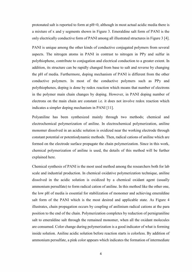
Chemical synthesis of PANI is the most used method among the researchers both for lab
scale and industrial production. In chemical oxidative polymerization technique, aniline
dissolved in the acidic solution is oxidized by a chemical oxidant agent (usually
ammonium persulfate) to form radical cation of aniline. In this method like the other one,
the low pH of media is essential for stabilization of monomer and achieving emeraldine
salt form of the PANI which is the most desired and applicable state. As Figure 4
illustrates, chain propagation occurs by coupling of anilinium radical cations at the para
position to the end of the chain. Polymerization completes by reduction of pernigraniline
salt to emeraldine salt through the remained monomer, when all the oxidant molecules
are consumed. Color change during polymerization is a good indicator of what is forming
inside solution. Aniline acidic solution before reaction starts is colorless. By addition of
ammonium persulfate, a pink color appears which indicates the formation of intermediate

5
oligomers. Then a deep blue color shows the presence of protonated pernigraniline salt
and finally, green color denotes reduction to emeraldine salt PANI [12].
Initial studies on chemical synthesis of PANI were performed at room temperature but
resulted in low molecular weight and significantly branched product which showed low
conductivity as well. The reason was ascribed to ortho-coupling of anilinium radical
cations instead of para-coupling, which resulted in a structure full of defects and branches
[13, 14]. To overcome such problem, low temperature (1-5 °C) polymerization was
suggested and successfully achieved PANI emeraldine salt with a molecular weight of
30,000-60,000 g/mol. Even lower temperatures up to -40 °C together with additive salts
such as CaF2 and LiF showed to increase the molecular weight of PANI up to 417,000
g/mol [16].
Figure 4. Mechanism of oxidative polymerization of aniline by ammonium persulfate in
acidic solution. (a) initiation, (b) chain propagation, (c) termination by reduction of
pernigraniline salt to emeraldine salt. (HA denotes an acid with counter ion A-) [15].
(a)
(b)
(c)
(NH4)2S2O8
6
Since discovery of electrical conductivity in PANI, it has received so much attention and
it has been investigated for numerous different applications including supercapacitors
[17], electrochromic displays [18], fuel cells [19], anticorrosion coatings [20], smart
membranes [21], sensors [22] and actuators [23].
1.4. Polyaniline nanofibers; synthesis, properties and applications
One-dimensional (1D) nanostructures including nanowires, nanorods, nanotubes etc.
which have width or diameter less than 100 nm have shown interesting properties and
received much attention during last two decades. However, in contrast to some inorganic
compounds such as ZnO and GaN for which 1D growth is well-established and effective
parameters are well studied, for many organic polymers, synthesis procedures are not
well-established. For this reason, achieving 1D nanostructures of organic polymers is of
great importance and highly desired [24].
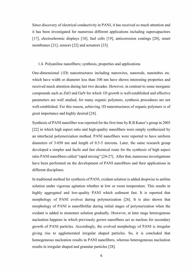
Synthesis of PANI nanofiber was reported for the first time by R.B Kaner’s group in 2003
[22] in which high aspect ratio and high-quality nanofibers were simply synthesized by
an interfacial polymerization method. PANI nanofibers were reported to have uniform
diameters of 3-050 nm and length of 0.5-5 microns. Later, the same research group
developed a simpler and facile and fast chemical route for the synthesis of high aspect
ratio PANI nanofibers called “rapid mixing” [24-27]. After that, numerous investigations
have been performed on the development of PANI nanofibers and their applications in
different disciplines.
In traditional method for synthesis of PANI, oxidant solution is added dropwise to aniline
solution under vigorous agitation whether at low or room temperature. This results in
highly aggregated and low-quality PANI which sediment fast. It is reported that
morphology of PANI evolves during polymerization [26]. It is also shown that
morphology of PANI is nanofibrillar during initial stages of polymerization when the
oxidant is added to monomer solution gradually. However, at later stage heterogenous
nucleation happens in which previously grown nanofibers act as nucleus for secondary
growth of PANI particles. Accordingly, the evolved morphology of PANI is irregular
giving rise to agglomerated irregular shaped particles. So, it is concluded that
homogeneous nucleation results in PANI nanofibers, whereas heterogeneous nucleation
results in irregular shaped and granular particles [28].

7
The successful strategy for achieving nice PANI nanofibers is concluded to be avoiding
heterogeneous nucleation during chemical oxidative polymerization. To do so, it is
possible to stop the reaction in the initial stage before secondary growth begins. However,
the yield of the method is very low, and it is not suitable for large-scale production. The
final modification that is used is to rapidly mix all oxidant solution with monomer
solution in one shut instead of gradual addition, to create many homogenous nucleation
points simultaneously. Besides, the concentration of the oxidant should be less than
monomer to confirm complete consumption of oxidant molecules in the initial stage of
polymerization [25].
There are some important parameters in regard to achieving high aspect ratio nice
nanofibers of PANI in rapid mixing method which are described briefly. An important
parameter is agitation or stirring during polymerization. It is shown that any kind of
agitation helps heterogeneous nucleation and secondary growth of PANI leading to
irregularly shaped particles [28, 29]. So, it is essential to put the reaction vessel still
without any mechanical agitation during polymerization.
Another important factor is the type of acid and oxidant for rapid mixing technique. Three
acid type namely, camphorsulfonic acid, perchloric acid and hydrochloric acid were
investigated to affect the morphology of grown PANI nanofibers. It is reported that using
hydrochloric acid, camphorsulfonic acid and perchloric acid results in nanofibers with an
Figure 5. Schematic of the so-called rapid mixing method for synthesis of PANI
nanofibers.
Oxidant solution
Aniline solution

8
average diameter of about 30 nm, 50 nm, and 120 nm, respectively. Also, a narrow
distribution of diameter is observed for all kind of acids used [22, 26].
Ammonium persulfate is the typical and most used oxidant for the polymerization of
aniline. other oxidants are also used including FeCl3, silver nitrate, H2O2, ferric sulfate or
even their combinations. As a rule, oxidants with E0>1 V (such as persulfates,
dichromates, etc.) can oxidize aniline in acidic medium. Weaker oxidants may result in
low-quality or branched polymer [30]. On the other hand, very strong oxidants may result
in heterogeneous nucleation of PANI on preformed particles, which results in irregular
shape product. So, attaining high aspect ratio PANI nanofibers best results have been
reported for ammonium persulfate.
Since the invention of PANI nanofiber synthesis method by R.B Kaner research group
many studies have been done to develop and make use of PANI nanofibers for various
applications. The key processing feature of rapid mixing method, in addition to simplicity
and cost-effectivity of the method, is that it finally delivers a well-dispersed stable
suspension of PANI nanofibers in emeraldine salt state which is the most applicable state
of PANI, ready for application. In this regard, thin or thick films of PANI nanofibers can
be easily prepared by a variety of techniques like spraying, dip coating, or simple casting
of a stable suspension. Furthermore, rapid mixing method involves no stabilizer,
dispersant or any organic additive which makes it a versatile technique for different
applications [25].
1.5. Mechanism of actuation in PANI
Figure 6 illustrates oxidation states of PANI as well as the protonation states in details.
As it is seen, all state transforms involve either counterion or proton transport. This is the
basic reason of volume change in PANI. By increasing oxidation level of PANI (moving
vertically down in Figure 6) polymer backbone becomes positive. To compensate this
charge and keep charge neutrality, PANI absorbs acid counterions from surrounding
media. Insertion of acid counterions results in expansion of PANI chains and polymer
volume increases. This volume change can be utilized for actuation of the bulk polymer.
Accordingly, for actuation of PANI path 1 in Figure 6 is suitable, since along path 1
leucoemeraldine base (LB) transforms to emeraldine salt (ES). This transform is
accompanied by absorption of acid counter ion and PANI expands [31-33] and its mass
increases [31]. However, along with the path 2, from ES to pernigraniline base (PB) the

9
polymer releases some ions and contracts [34, 35]. Due to the instability of pernigraniline
state in most of the acidic media, for actuation of PANI, path 1 is typically used.
Water transport is another important aspect in actuation of PANI, although it is not
included in the actuation schematic of Figure 6. We know that ions are hydrated in
aqueous media. So, by transferring counter ions and protons, some water molecules are
also transferred. In addition, due to interactions of water and PANI, the osmotic pressure
changes, and this results in an independent water flow which definitely affects actuation
of PANI. It is reported that up to ten water molecules can accompany an ion which creates
a substantial influence [35]. However, there is no agreement on a specific model among
the researchers to include water transport in PANI.
Electrochemical properties of PANI has been investigated and well documented in the
literature using cyclic voltammetry (CV) technique [5, 36]. Positions and intensities of
the peaks greatly depend on CV measurement details such as electrode area, voltage
range, scan rate, pH of the electrolyte and preparation method of PANI. Nevertheless, the
general voltammogram of typical PANI can be shown in Figure 7. The CV curve of PANI
in an acidic solution shows two distinct pairs of redox peaks. The first redox pairs occur
at about 0.2 V vs. Ag/AgCl reference electrode. In the forward scan, the anodic peak is
ascribed to the conversion of leucoemeraldine to partially oxidized emeraldine salt form
Figure 6. Electrochemical oxidation states of PANI in salt and base forms. A- denotes
acid counter ion [8].

10
of PANI. The second peak pair which occurs at about 0.7 V associates with oxidation of
emeraldine salt to pernigraniline salt. It is reported that pH of media affects the potential
of first redox pair while the potential of the second pair is independent of pH [36]. This
shows that protons contribute to reaction mechanism in the second redox reaction but not
in the first one. This issue is shown in the reaction path and chemical structure of PANI
in Figure 7.
Another notable aspect of PANI is its doping behavior. Most of the electroactive polymers
get doped electrochemically i.e. by changing the oxidation state of the polymer in which
total number of electrons on the polymer backbone changes. However, PANI in addition
to that can get doped by a non-redox procedure of changing the pH of media in which
total number of electrons on the polymer backbone remain constant [11]. Simpler pH
doping behavior of PANI facilitates working with PANI and therefore expands its
applications’ domain.
Doping PANI with acidic solutions results in the formation of radical cations at imine
nitrogen atoms which are mainly responsible for electronic conduction mechanism in
Figure 7. A typical CV curve of PANI in HCl, depicting two sets of redox peaks. the
undertaking reactions are shown for each peak [36].

11
PANI. The fact that leucoemeraldine and pernigraniline states of PANI are both insulating
implies that the number of radical cations increases with decreasing the pH and it is
consistent with the given chemical formula of PANI states. In the other word, emeraldine
salt form of PANI shows the highest conductivity forms in lowest pH which indicates that
it owns the highest number of radical cations. Therefore, the highest conductivity is
achieved when PANI is fully protonated but half-oxidized i.e. PANI emeraldine salt.
Overoxidation of PANI beyond the potential of 0.7 V results in the formation of
quinonediimine which is a non-conductive, non-electroactive structure [37].
1.6. Designing an actuator using PANI nanofibers (NF)
Electro-actuation has been observed in many electroactive polymers such as,
poly(ethylene dioxythiophene) [38], poly(p-phenylene vinylene) [39], polypyrrole [40],
polythiophenes [41] as well as polyaniline (PANI) [23]. Although electrochemistry and
actuation behavior of PANI with different morphologies are well-studied [8, 42-46],
electroactuation of polyaniline nanofibers (PANI NFs) are rarely investigated[47, 48].
Baker et. al reported chemo-actuation of flash-welded PANI NF film in acidic and basic
media [49]. PANI NFs synthesized through so-called rapid mixing method[48], [26, 50]
have merits of high charge/discharge rate [51], high surface area [52], high molecular
weight [53], and good conductivity [54] all of which contribute to high electrochemical
activity and thus high actuation stroke. However, the main problem of PANI based
actuators is that they need to work under acidic solutions because the mechanism of
expansion and contraction of PANI is based on, respectively, injection and rejection of
ions due to applied electric potential stimuli. This limitation restricts the application of
PANI-based actuators in many fields especially biology (human artificial muscles) and
soft robotics. To overcome this limitation, a gel electrolyte soaked in the acid solution
can be sandwiched between two PANI electrodes to supply ions for actuation as well as
keeping PANI electrodes wet. Although this idea is not recent [55], there are not many
studies on PANI actuators [56, 57]. In a recent work [56], Liu et al. have prepared PANI/r-
GO nanocomposite active electrode and sandwiched PVA/sulfuric acid between two
electrodes as gel electrolyte to make an air-working actuator. However, using r-GO may
affect the total conductivity of active electrode and result in slower kinetics.
Another way to address this problem is using ionic liquids as electrolyte [58]. It is shown
that durability and long-term stability [59] of actuators improve very much and they can
work in the air as well [60]. However, ionic liquids are usually moisture sensitive [61],

12
expensive, toxic and environmentally harmful [62], which limit their usage in
bioengineering and biomimetic applications. For these reasons, we selected aqueous
electrolyte although it is important to preserve the humidity of the environment in order
to maintain the long-term stability due to water evaporation from the electrolyte.
In this thesis, a bending actuator using PANI NFs which can work in the air as well has
been designed and prepared. Supplying mobile ions, cross-linked PVA as gel electrolyte
was sandwiched between two electrodes. PVA is a hydrophilic polymer which can absorb
water if gets mildly cross-linked. Glutaraldehyde is a well-known and well-studied cross-
linking agent of PVA [63, 64] and was used in this study as well. Mildly cross-linked
PVA grants high flexibility and film-forming ability of pristine PVA as well as water
absorbance property of a gel electrolyte. Our proposed actuator with the use of PANI NFs
demonstrated interesting results in terms of very low excitation voltage, stability and high
actuation stroke when fully doped and the challenge of stable air-working actuators.
1.7. Ionic polymer metal composites (IPMC)
Ionic polymer-metal composites are an important family among polymeric actuators
which utilize ionic conductivity of a polyelectrolyte membrane. A typical IPMC is made
of an ionically conductive polymer electrolyte membrane which is electroded on both
sides. The ion exchange conductive membrane is composed of fixed negative moieties
among which positive ions hydrated with water can migrate [65]. By application of
electric field between metal electrodes, cations hydrated by water molecules migrate
toward the cathode and accumulate near the electrode interface, whereas negative
moieties are fixed in the polymer network and cannot compensate volume change due to
the accumulation of cation clusters and water electro-osmosis [66]. This volume change
can be utilized to convert into shape change such as bending of the membrane in
cantilever kind of actuators.
The basic component of any IPMC sensor or actuator which plays a crucial role in
functioning is the ion-exchange material or sometimes called ionomer. The ion-exchange
material is usually an organic polymer which has a long backbone with side branches that
include fixed ionic groups. This structure enables the ion-exchange polymer to selectively
pass some ions which can be single-charged or multiple-charged anions or cations
depending on the chemical structure.

13
Nafion, as the most typical ion-exchange polymer has a Teflon like structure; a
perfluorinated backbone with side chains end in sulfonate or carboxylate groups (Figure
8). In such structures, large backbone determines mechanical properties of the polymer
and side branches with ionic groups determine the ion selectivity properties.
The other ion-exchange polymer that is popular in membrane industries as well as fuel
cell researches is a copolymer of divinylbenzene and styrene. Cation exchange property
is given to the polymer by sulfonation of styrene. Although there several ion-exchange
polymers have been invented and developed by various technologies, Nafion is the most
used one for sensing and actuation.
1.8. Manufacturing of IPMCs
As explained before, an IPMC is composed of an ion-exchange polymer film which is
electroded at both sides. This electrode conducts electric field uniformly throughout the
ion-exchange film and increases the diffusion of ions inside IPMC. However, the type
and thickness of electrode should be optimized in such a way that it should not make
IPMC stiff, not to hinder its movement. In addition, the metal electrode should be very
stable both chemically and mechanically and should not get separated or get into reaction
with environment especially during hydration or after hundreds of working cycles [68].
There are two main classes of methods for electroding IPMCs; physical techniques and
chemical techniques. Chemical methods involve electroless plating techniques while
physical methods such as sputtering, physical vapor deposition, and solution casting are
alternatively used to form a uniform metal layer. Chemical methods are more time-
consuming and involve harsh chemical conditions, whereas physical methods are cleaner
and faster and form a more uniform electrode layer. However, in practice, chemical
methods resulted in better performance and longer lifetime due to better adhesion to ion-
exchange polymer membrane in hydrated conditions [68]. In this thesis chemical
electroless plating is used for electroding the ion-exchange membrane. So, here details of
the method will be briefly described.
Figure 8. The common chemical structure of Nafion. Na+ can be replaced with other
cations [67].
14
Electroless plating method has been reported to be the most successfully used method for
electroding the IPMCs [69]. In the literature, several similar recipes are reported for
fabrication of IPMC using Nafion or any other ion-exchange polymer [67, 70, 71]. Figure
9 illustrates the general route for the preparation of an IPMC based on Nafion. The
methods are generally composed of three main steps, namely pretreatment, ion exchange
and reduction. In pretreatment step, the goal is to prepare the surface ion-exchange
polymer membrane for the next steps which includes deposition of Pt particles. To do so,
surface roughening techniques are employed to create roughness and increase surface
adhesion of electrode to the polymer. Sandblasting with sandpaper or sawdust of different
particle size is a common method. This step is usually followed by chemical or ultrasonic
cleaning of the membrane in acidic solutions.
The second step includes penetration of Pt cations into the roughed membrane to
exchange ions. Doing so, Pt metal complexes such as [Pt(NH3)4]Cl2 and [Pt(NH3)6]Cl4
have been mostly used and resulted in fine electrodes. Time needed for complete
dissociation of Pt complex and ion exchange ranges from 1 hour to 1 day.
The third step of electroding incorporates the reduction of Pt cation to metallic Pt particles
on the surface or in the bulk of membrane but near the surface using strong reducing
agents such as NaBH4 and hydrazine solution. Since the third step usually results in a thin
layer of Pt electrode on the surface, to enhance the conductivity of the surface, steps of
ion exchange and reduction can be repeated up to three times [67].
Concentration of Pt salt and reducing agents, temperature of the medium during reduction
step, stirring of solution and duration of reaction are among the important parameters that
define the final morphology of electrode and hence affect electrical properties of IPMC.

15
1.9. Mechanism of Actuation in IPMCs
As briefly mentioned before, ion migration is the fundamental basis for actuation of
IPMCs. Figure 10 shows the mechanism of actuation for a typical IPMC. In the normal
condition, positive ions which can be protons or metal cations are dispersed throughout
the polymer membrane. when a potential is applied to the IPMC, positive cations which
are free to move, migrate toward the cathode and accumulate there whereas negative
moieties are fixed in the polymer network and cannot compensate volume change due to
the accumulation of cation clusters and water electro-osmosis [66]. This volume change
can be utilized to convert into shape change such as bending of the membrane in
cantilever kind of actuators.
Figure 9. Fabrication method of an IPMC based on Nafion [69].

16
A model that is proposed by Nemat Nasser includes elastic, osmotic, electrostatic and
hydraulic forces to explain actuation movements in Nafion [72]. It is finally concluded
that a balance between electrostatic forces and osmotic pressure from one side with elastic
forces of ion-exchange polymer from another side results in actuation. This model
proposed an explanation for the back relaxation of Nafion. Accordingly, redistribution of
cations in cathode due to a decrease in osmotic pressure in the anode side of IPMC
because of depletion of cations can be a reason for back relaxation of Nafion. Although,
the direction of back relaxation depends on the type of cations and nature of the ion-
exchange polymer. In anode side, depletion of cations induces the repulsive forces
between fixed ions in the ion-exchange polymer and this results in local expansion and
flow of excess water molecules toward the anode, which contributes in back relaxation
mechanism.
In the cathode side of IPMC, accumulation of cations leads to reduction of electrical
permittivity of clusters and thus increase in electrostatic attraction forces between cations
and fixed anions. It is shown that this phenomenon which is called electro-osmotic
pressure contribute to back relaxation of IPMC toward cathode [73].
1.10. Radiation grafted polymers
The structure of a grafted copolymer can be described as the main polymer backbone
which is connected to some side branches as a block. The side chains have different
Figure 10. Mechanism of actuation in a typical IPMC.

17
configurational or constitutional properties than the main chains. Therefore, with altering
the nature of side chain and main chain a combination of variant properties can be
expected from the grafted copolymer. This feature grants excellent possibilities to design
and fabricate novel and optimized polymers for different applications. Radiation-induced
grafting includes two main steps; creating free radicals on main polymer chains and
polymerization and growth of side chains. This method has the advantage of
polymerization of some monomers that are hard to polymerize through conventional
ways. Besides, since no initiator molecule is required, polymerization system is simpler
and high polymerization temperatures, residue of initiator molecules and catalysts can be
avoided.
Figure 11 shows the schematic of radiation-induced grafting copolymerization reaction.
As it is seen, monomer polymerization and radical formation can be simultaneous, or
irradiation can be done in advance and growth as the next step.
In this topic, the most important parameters of graft copolymerization will be briefly
described including radiation rate and dose, nature of the base polymer, monomer
concentration, graft temperature and medium.
1.10.1. Radiation source and dose
Source of radiation can be particles such as high energy ions/electrons or photons such as
X-ray / γ-ray. The properties of result copolymer strongly depend on the type of
Figure 11. Reaction schematic for radiation-induced graft copolymerization with
different methods [74].

18
irradiation. The basic difference between them is the depth of penetration. High energy
photons can penetrate deeper into the bulk of the materials and membranes while
irradiation of high energy electrons is limited to nearly surface of membranes. In addition,
photon irradiation has the advantage of controllability of dose rate according to
attenuation of passing wave. Today, Co60 is the mostly used irradiation source with a half-
life of 5.3 years and average irradiation energy of 1.25 MeV. The radiation dose is defined
as the amount of emitted energy toward the specimen. The most used unit for radiation
dose is Gray (Gy) and kGy. One Gy is equal to 104 erg/s. In this regard, the dose rate is
defined as the amount of energy per unit of time that the specimen receives.
1.10.2. Nature of base polymer
The chemical structure of the base polymer is of great importance in radiation grafting of
membranes. In this regard, fluorinated base polymers have been attractive to researchers
more than other polymers due to their thermal and chemical stability. In addition, they
offer structural modifiability which is very useful property in membrane technology. In
this respect, fluorocarbon and hydrocarbon structures including polyethylene (PE),
polytetrafluoroethylene (PTFE), Poly(tetrafluoroethylene-co-hexafluoropropylene)
(FEP), poly(ethylene-alt-tetrafluoroethylene) (ETFE) and poly(vinylidene fluoride)
(PVDF) have been promising candidates. The basic physicochemical properties of the
base polymer like molecular weight, Tg, membrane thickness etc. affect the grafting and
final product properties to much extent. For instance, it is believed that increasing in
molecular weight of base polymer results in a decrease of graft level. It is also reported
that higher radiation dose is needed for thinner base polymer films to obtain comparable
graft level with a thicker one [75]. The interesting feature of irradiation grafting is pre-
graft storage of membranes in which the membrane or the base polymer is irradiated in
vacuum previously and preserved at low temperature to keep the free radicals. It is
observed that fluorinated polymers (ETFE and PVDF) irrespective of chemical structure
can preserve free radicals at temperature of -18 °C for longer than a year [76]. This feature
creates potential processing opportunities to irradiate membranes and keep them at low
temperature for later use.
1.10.3. Monomer concentration
Concentration of monomer is probably the most effective parameter in the radiation graft
copolymerization. Increasing the monomer concentration increases diffusion paths of

19
monomers toward propagating polymer chain and thus results in graft level enhancement.
However, monomer concentration has an optimum level beyond which graft level drops
rapidly due to a sudden increase in homopolymerization. Effect of styrene concentration
on radiation grafting into ETFE is investigated by S. A. Gürsel et al. in water/ethanol
solvent [75]. The optimum monomer concentration is reported as 20 vol. % for 2 hours
reaction time. Beyond such concentration, a decrease in the graft level is observed.
Interestingly, a similar trend is reported for grafting of styrene into PTFE and FEP
membranes. The monomer concentration at which maximum grafting degree occurs can
be altered by other parameters such as solvent type and reaction medium. Grafting chains
must swell in the solvent to allow monomer diffusion and increase the graft level.
1.10.4. Graft temperature and medium
The grafting reaction temperature has a substantial effect on graft level and final product
properties. It is observed that increase in medium temperature, generally results in a
decrease in the graft level. However, initial grafting rate shows a sudden increase with
increasing of temperature. To explain this opposite behavior, it should be mentioned that
graft level is controlled by three different factors working at the same time; monomer
diffusion, chain termination and loss of active radicals. As the grafting temperature
increases, the monomer diffusion also increases and results in acceleration of chain
initiation and propagation. Consequently, graft rate initially increases. However, at the
same time, active radicals may become deactivated in higher temperatures. In addition,
since grafted chains remain swollen in the grafting zone, the mobility of swollen chains
increases. Thus, chain termination dominates in higher temperatures. This results in
lowering of final grafting level in higher temperatures. This phenomenon has been
observed for grafting of styrene into ETFE in different studies. A reason for such behavior
can be related to Tg of the polymer. If the Tg of the grafted polymer is lower than the
reaction temperature, chain mobility increases, and chain termination is dominant, which
results in a lower degree of graft. However, in the same condition higher initiation and
propagation rates may result in a rapid increase in graft level. Therefore, precise
prediction of graft level is very difficult since it depends on many parameters at the same
time [75].
The monomer and grafting copolymer chains come together through a medium that is
solvent. A proper solvent should swell both monomer molecules and propagating polymer
chains. If the solvent does not swell either of them very well, only a surface and non-

20
homogeneous grafting may occur. However, choosing proper solvent results in
homogeneous bulk grafting especially for grafting of membranes. In this regard, nature
of solvent and additives are of great importance. Alcohols, benzine dichloromethane, and
toluene are investigated for grafting of styrene and styrene derivative monomers. It is
believed that both solubility parameter and chain transfer constant of the solvent are to be
considered in this regard. For example, benzene with solubility parameter of 18.6 is more
likely to result in higher grafting level of styrene with solubility parameter of 19
comparing with dichloromethane and methanol with solubility parameters of 17.6 and
29.7, respectively. Another important factor is chain transfer constant of the solvent. It is
reported that solvents with low chain transfer constants give rise to higher graft levels
because growing chain in low chain transfer constant has greater propagation step which
results in higher graft levels. This constant for methanol, dichloromethane, and benzene
are 0.296, 0.15 and 0.2, respectively.
Another interesting factor that influences the degree of graft is using non-solvents.
Normally it is believed that using non-solvents results in lowering of swelling of
propagating chain or the monomer and thus lowering the diffusion of monomer toward
growing chains which gives rise to lowering graft level as well. However, some
investigations showed the opposite trend. In case of grafting of polystyrene on PVDF
partially substitution of toluene with some alcohols which are non-solvent for polystyrene
resulted in an increase of grafting level up to 4 times. The reason has been ascribed to
auto-termination effect because of limitation of diffusion of monomer molecules due to a
localized increase in viscosity. This effect is observed to be higher by using, in order,
propanol, ethanol, and methanol. The local higher concentration of monomer due to
higher viscosity is reported to be the reason for higher grafting level when propanol is
used [75].
1.11. Designing an IPMC using PVDF-g-PSSA
Nafion (DuPont) is a traditional and the most studied ionic polymer for making IPMCs
due to its good proton conductivity, chemical stability, availability and good repeatability
of performance. However, it has some drawbacks such as complicated production steps,
high production cost, low water uptake (WU) and not being environmentally friendly,
which limit its applications [68, 69, 77]. Consequently, there has been motivation to
explore replacement of Nafion in making versatile and commercial IPMCs [78].

21
Generally, polymer electrolytes which are used as IPMC benefit from either carboxylic
acid [79] or sulfonic acid group [80-82] as main functional group to grant proton
conductivity to an ordinary polymer backbone. In the latter category, radiation grafting
of vinyl monomers onto fluoropolymers has been proposed as a preparation method and
investigated to be used as IPMC actuator [82, 83]. In this regard, poly(styrene sulfonate)
is grafted on various backbones including poly(vinylidene fluoride)-co-
(hexafluoropropylene) [80], poly(ethylene-co-tetrafluoroethylene) [81], and
poly(tetrafluoroethylene-co-hexafluoropropylene) [82]. In this method, a fluorinated
polymer is irradiated by high energy electrons or rays to create free radicals on the
backbone which can later initiate polymerization reactions [74, 84]. Afterward, grafted
polymer is sulfonated using usually sulfuric acid or chlorosulfonic acid which requires
tedious and very careful laboratory work.
a novel method is used to perform grafting and sulfonation process in one step without
involving harsh conditions [85] . We selected PVDF as polymer backbone and PSSA was
directly radiation grafted on it to prepare PVDF-g-PSSA as proton conductive material.
This system has been characterized and studied well for the proton exchange purposes
[86-89], however, to the best of our knowledge study on the actuation behavior is lacking.
Panwar et al. research group has reported several studies on an actuator system of similar
constituent materials, but they are all based on a blend of PVDF, PSSA and poly(vinyl
pyrrolidone) (PVP), and no radiation-induced grafting was involved. Their results show
higher ion exchange capacity (IEC), WU and enhanced actuation performance compared
with Nafion [90-92].
In this thesis, PSSA was directly radiation-induced graft polymerized on PVDF in
solution to donate proton conductivity to the backbone. Details of the graft reaction, its
mechanism, and effective parameters are reported elsewhere [85] . Here, with altering
sulfuric acid concentration as the grafting parameter, three different graft levels of
poly(sodium styrene sulfonate) (PSSS) on PVDF were achieved. Membranes were
fabricated by solution casting of synthesized polymer and activated by acid treatment.
IEC, as well as WU and proton conductivity of prepared membranes for various graft
levels, were investigated and compared with Nafion. Electromechanical bending of the
PVDF-g-PSSA based IPMC actuators was finally demonstrated by a cantilever form of
sample using AC voltage in the air and compared with Nafion as a typical IPMC
benchmark material.

22
1.12. Contributions of this thesis
In this thesis, two actuation systems were designed, fabricated and characterized. In the
first system, high aspect ratio PANI nanofibers were used to create actuation stroke.
Forming a porous microstructure, high aspect ratio PANI nanofibers provided large
surface area for the acid counter ions to defuse into/out of the actuating electrode. This
resulted in total bending displacement as high as 20 mm under 1 M HCl at frequency of
50 mHz consuming a low potential of 0.5 V. Total displacement of the actuator under the
acid solution was stable for 1000 cycles at frequency of 1 Hz. The enhanced performance
of this bending actuator was attributed to optimized porosity of PANI nanocomposite
actuator as well as high reversibility of PANI nanofibers according to cyclic voltammetry
curves.
In the second system, a grafted electroactive polymer was synthesized through a novel
method and was used as ion exchange membrane of IPMC actuator. Inspired by proton
conduction mechanism of Nafion, polystyrene sulfonic acid was radiation graft
polymerized as side branch on PVDF backbone. Physical properties of the grafted
polymer including ion exchange capacity, proton conductivity and water uptake of the
grafted polymer was investigated and compared with Nafion. According to the results,
membrane with the highest graft level (35 wt.%) showed ion exchange capacity of 1
mmol/g and proton conductivity of 82 mS/cm which are almost as high as Nafion.
However, it exhibited nearly 3 times greater water uptake (62 wt.%) than Nafion. The
reason was attributed to high sulfonic acid content of the grafted membrane as well as
presence of cluster networks in Nafion due to orientation of sulfonic acid groups. Higher
water uptake in the actuator (G35) gave rise to enhanced average bending strain of 920
x10-6 at 4 V and 0.1 Hz in air which is superior than Nafion. The results reported herein
suggest that PVDF-g-PSSA can be a promising candidate for Nafion in many applications
as soft actuator and sensor.

23
2. Materials and Methods
2.1. Materials
Aniline, p-phenylenediamine (p-PDA), ammonium persulfate (APS), polyvinyl alcohol
(PVA) (Mw = 89,0000-98,000, 99% hydrolysis), glutaraldehyde, 25 wt.% in water (GA),
and hydrochloric acid were purchased from Sigma-Aldrich and used as received.
Very high molecular weight (Mw = 573,000) PVDF powder (Solef®) was purchased
from Solvay. Nafion® 115 were purchased from Fuel Cell Store (USA). Styrene-4-
sulfonic acid sodium salt (SSS), dimethyl sulfoxide (DMSO), sulfuric acid (H2SO4),
hydrochloric acid (HCl), tetraamineplatinium chloride hydrate ([Pt(NH3)4]Cl2),
hydroxylammonium chloride (NH2OH·HCl), sodium borohydride (NaBH4) and methanol
were all purchased from Sigma Aldrich. All materials were reagent grade and used as
received without any further purification. Deionized water (DIW) (Mili-Q, 18 MΩ) was
used during the synthesis and conditioning of graft copolymers
2.2. PANI nanofiber synthesis
PANI nanofibers were synthesized using so-called rapid mixing method [24, 26]. Briefly,
3.65 mL of aniline was dissolved in 100 mL of 1 M HCl. 0.054 g of p-PDA was dissolved
in minute amount of methanol and added to the monomer solution. p-PDA with two amine
functional groups is used to accelerate oxidative polymerization rate of PANI especially
when rapid mixing synthesis of PANI is required. It has been shown that small amount of
p-PDA gives rise to faster growth rate than nucleation rate which results in high aspect
ratio and less entangled PANI nanofibers [24]. In another vessel, 2.51 g APS was
dissolved in 100 mL of 1M HCl. Both solutions were stirred for 30 min, then were kept
in refrigerator at 4 °C for 30 min. Aniline and APS solutions were mixed together rapidly.
The mixture was shaken severely for 5 seconds, then stored in refrigerator at 4 °C for 24
hours to complete the polymerization. Purification of nanofibers was done using a 4-step
centrifuge plan. In each step, the precipitate was diluted with HCl solution (pH=2.5), re-
dispersed by shaking vigorously, and centrifuged (5000 rpm, 15 min). The supernatant of
3rd and 4th steps were used as stable suspension of PANI nanofibers for film preparation

24
2.3. PANI emeraldine salt (ES) nanofiber electrode preparation
In a typical procedure, a cleaned microscope glass slide was coated with high purity gold
(commercial 1g gold coin, 99.99%) using thermal evaporation technique (Torr
International Inc.). Thickness was adjusted to 30 nm.
Polyvinyl alcohol was dissolved in hot 1M HCl at 90 °C to form a clear 4 wt.% solution.
2.5 mL of PVA solution was mixed with 15 µL GA (2.5 wt.% in water) and stirred for 30
min at room temperature and followed by 30 min stirring at 50 °C to complete cross-
linking reaction. The cross-linked PVA stock solution (CL-PVA) was then stored at room
temperature.
2 mL of PANI ES NF suspension (3 mg/mL) in HCl (pH=2.5) was mixed with a proper
amount of CL-PVA solution (PANI NF / CL-PVA=80 / 20 by weight) at room
temperature and stirred for 30 min. Next, it was drop casted on a gold-coated glass slide
(25 x 38 mm) and dried on a leveled hot plate at 50 °C for 3 hours. Resultant
nanocomposite PANI ES NF/CL-PVA electrode films with a thickness of 10-15 were
easily peeled-off by adding a little water.
2.4. PANI nanocomposite actuator preparation
Hot-pressing technique was utilized to prepare actuator composite. About 0.5 mL of CL-
PVA stock solution was sandwiched between two films of PANI ES NF/CL-PVA
electrodes at 45 °C for 30 min with a pressure of 2 MPa. Prepared films were cut into
dimension (3 x 20 mm) for actuation test.
2.5. Direct radiation induced grafting of poly(styrene sulfonic acid) on PVDF
Radiation-induced grafting method was used by an innovative method for direct
polymerization of sodium styrene sulfonate on PVDF backbone. PVDF powder weighted
and packed in small polyethylene plastic bags. Irradiation process was performed by γ-
rays from 60Co source at 100 kGy total irradiation dose at room temperature (Gamma-
Pak Sterilization, Çerkezköy, Turkey). Afterward, irradiated PVDF was kept in a deep
freezer at -80 °C before further use. Graft polymerization was performed in a mixture of
aqueous DMSO and H2SO4. Aqueous DMSO solution was prepared by DIW: DMSO =
1:4 (volume ratio) and H2SO4 concentration, as the main grafting condition, was varied
from 0.2 to 1 mol/L. Two monomer (SSS) concentrations of PVDF:SSS = 1:1 and 1:2
(weight ratio), were selected. A 100-mL round flask was filled with 40 mL of prepared

25
aqueous DMSO and 10 mL of H2SO4 solution. The desired amount of monomer was
dissolved in the solution and was degassed with N2 for 30 minutes. 5 g of irradiated PVDF
was added to the flask directly from freezer, and the polymerization reaction was
proceeded for 8 hours at 60 °C in an oil bath under vigorous stirring. After grafting, the
resultant polymer was precipitated firstly by acetone, then by methanol and washed with
distilled water (DW). Finally, rinsed grafted polymer was filtered by filter paper and dried
in an oven for 24 hours at 60 °C.
2.6. Preparation of IPMC actuator
0.26 g of PVDF-g-PSSS was added to 2 mL of DMSO to form a 13 w/v% solution at 60
°C under stirring for two hours. The viscous solution was sonicated in hot water bath to
extract air bubbles for 5 minutes. 2 mL polymer solution was cast on a clean and oxygen-
treated microscope glass sheet (2.5x7 cm2) at room temperature and dried in a pre-heated
oven at 180 °C under vacuum for 15 minutes followed by cooling down to room
temperature slowly inside the oven. To convert grafted polymer (PVDF-g-PSSS) to acidic
form (PVDF-g-PSSA), prepared membranes were treated with 1 M HCl solution at 50 °C
overnight to remove sodium ions and get protonated. Then, membranes were peeled-off,
rinsed with and soaked in DW for 1 hour. The thickness of the dried membranes was
measured using a digital micrometer and found in the range of 80-100 µm.
Electroding of the PVDF-g-PSSA membranes, as well as Nafion membrane, were
performed using electroless plating method [70, 71]. Electroless plating generally
includes three main steps, namely pre-treatment, ion exchange, and reduction.
Membranes were cut into pieces with a dimension of 2x5 cm2. Briefly, Nafion membrane
surfaces were roughened by using sandpaper of 1200 grit. However, grafted membranes
did not need the sanding due to their porous nature (Figure 30). The membranes were
sonicated in DW for 15 minutes to remove any debris from the surfaces, then were treated
in 2 M HCl solution at 50 °C for 30 minutes followed by sonication in DW for 30 minutes.
Membranes were stored inside DW before further use.
Pre-treated membranes then were ion exchanged in which Pt cations were exchanged with
H+. 40 mg Pt salt ([Pt(NH3)4]Cl2) was added to 80 mL of DIW and 1.7 mL ammonia
solution (5wt.%) was added to keep the pH neutral. The membrane was soaked in the
above mentioned solution for 2 days under gentle stirring to complete ion exchange
process. Then, membranes were rinsed with DW.

26
Reduction of Pt cations to metallic Pt was done in two steps. In primary reduction, the
ion-exchanged membrane was soaked in 60 mL DIW at 40 °C. Then, every 30 minutes
0.67 mL of NaBH4 (wt.5%) was added to the reduction bath for 8 times under gentle
stirring. Temperature was gradually increased from 40 to 60 °C within 4 hours. In the
end, 6.67 mL of NaBH4 (wt.5%) was added to the solution and continued stirring for 1.5
hours at 60 °C to complete the reduction. The membrane was then rinsed with DW,
soaked in 0.1 M HCl for 1 hour, and rinsed with DW until the filtrate was neutral.
Since deposition of Pt on the surface of the membrane was not usually enough at this
point, a secondary plating step for reduction of Pt salt was carried out. 40 mg Pt salt was
added to 80 mL DIW and 1.7 mL ammonia solution (5%) to neutralize the solution. The
membrane was soaked in above-mentioned solution at 40 °C. Every 30 minutes, 2 mL of
NH2OH·HCl (5%) and 1 mL of hydrazine solution (20%) were added to the solution
under gentle stirring for 8 times. Within 4 hours, the temperature was increased from 40
to 60 °C gradually. Then, the membrane was rinsed with DW and soaked in 0.1 M HCl
for 1 hour and rinsed with DW until the filtrate was neutral. Finally, electroded actuator
membrane was cut into strips with a dimension of 5x40 mm2 and soaked in 1 M NaOH to
absorb Na+ cations before actuation test.
2.7. Characterizations methods
2.7.1. Morphological characterization
Microstructure and morphology of PANI ES NF/CL-PVA freestanding film were
investigated by FE-SEM (Zeiss, LEO Supra 35VP SEMFEG) and TEM (JEOL, JEM
200FX). The aspect ratio of PANI NFs was calculated and averaged using ImageJ
software.
Morphology of the solution cast membranes prior and after Pt plating was investigated
by FESEM (Cemini Supra 35 VP, LEO). Pt and sulfur concentration profile of the
membrane was analyzed by energy dispersive spectrometer (Bruker AXS Microanalysis,
GmbH) along the cross-section of the membrane.

27
2.7.2. Structural characterizations
Structural analysis of synthesized materials was performed using FT-IR (Thermo
Scientific iS10) with diamond crystal in ATR mode with a resolution of 2 cm-1. Chemical
structure of synthesized membranes was investigated by 1H NMR (VARIAN, INOVA,
AS500) using DMSO-d6 as solvent operating at 600 MHz.
2.7.3. Electrical conductivity of PANI NF film
Sheet conductivity of PANI ES film without gold coating was measured using 4-point
probe technique (Lucas Labs, PRO4-4400). for this purpose, a PANI NF/CL-PVA with
the identical procedure was prepared and cast on a clean glass microscope slide and dried.
After peeling-off, it was doped by 1 M HCl for 1 hour and dried at room temperature
under the hood. Dimensions of the sample after drying was 15 x 15 x 0.025 mm. The
conductivity of electrode film was measured using the formula below, where t is the
thickness of the film, I is the current passed by the current source and V is corresponding
potential drop.
( 1 ) σ =(ln2
πt)
I
V
Average value of 5 different points is reported as the conductivity of the nanocomposite
film electrode.
Electrical conductivity of PANI NFs was also measured using the same procedure. Dried
PANI NFs were mildly ground to open the agglomerates, then pressed into a pellet with
a diameter of 10 mm using a hand-press machine. The rest of procedure was similar to
PANI NF film.
2.7.4. Surface charge characterization of PANI NF
Surface charge of PANI NFs was measured by Zeta Sizer (Nano ZS, Malvern
Instruments). A few mL of PANI suspension was fed into special cuvette using a syringe.
A closed-cap cuvette was placed into Malvern Zeta Sizer and the measurement performed
at room temperature. Zeta potential was measured as the average of 20 separate sub-
measurements.

28
2.7.5. Electrochemical characterizations
Electroactivity of the prepared gilded active electrode was investigated by cyclic
voltammetry method (Gamry 3000 potentiostat/galvanostat/ZRA) using 3-electrode
arrangement with scan rates of 1, 5 and 10 mV/s. Prepared nanocomposite was used as
working electrode. A strip of gilded nanocomposite (3x20 mm) was immersed in 1 M HCl
in such a way that 10 mm of the strip was in the solution. Ag/AgCl and Pt wires were
used as reference electrode and counter electrode, respectively.
Electrochemical ion exchange behavior of PANI NFs was also investigated by
electrogravimetric method using electrochemical quartz crystal microbalance (EQCM).
About 1 g of PANI NFs were deposited on Au-coated quartz crystal electrode (10 MHz)
and was used in an electrochemical 3-electrode arrangement set-up (eQCM 10M, Gamry)
as working electrode. Pt wire and Ag/AgCl electrodes were used as counter and reference
electrode, respectively. 1 M HCl was used as the electrolyte. PANI NFs were cycled
between -0.2 and 0.6 V with the scan rate of 25 mV/s.
2.7.6. Mechanical characterization
Tensile strength and tensile modulus of the grafted membranes, as well as commercial
Nafion, were measured by universal testing machine (Zwick/Roell Z100) in both dry and
wet conditions. Gage length was 50 mm and test speed was 1 mm/min. Membranes were
cut into pieces with a dimension of 5x70 mm2. The average value of 5 samples was
reported.
Graft level (GL) of synthesized PVDF-g-PSSA was calculated through weight change of
the grafted polymer with respect to the pristine PVDF powder, using the equation below:
( 2 ) GL=Wg-Wp
Wp×100
where Wg and Wp are the weights of grafted and pristine PVDF powder, respectively.
2.8. Physical properties of membranes; water uptake, Ion exchange capacity and
Degree of sulfonation
Water uptake (WU) of the PVDF-g-PSSA membranes and Nafion were measured by
weight change of the membranes before and after water absorption using the equation
below:

29
( 3 ) WU=Ww-Wd
Wd×100
where Ww and Wd are the weight of membrane in wet and dry conditions, respectively.
To condition and measure Ww, membranes were soaked in DIW for 1 day. Then, the water
content on the surfaces was dried by a tissue. For measuring Wd, membranes were
completely dried at 60 °C for 6 hours in vacuum oven.
Ion exchange capacity (IEC) of the PVDF-g-PSSA membranes were measured using
back-titration method. First, the prepared membranes, as well as Nafion, were immersed
in 1 M NaCl solution for 2 days at 40 °C to exchange Na+ with H+. Then, H+ was titrated
with standard 0.025 M NaOH solution using automatic titrator (Mettler Toledo, EasyPlus
Easy pH). IEC was calculated by following equation [93, 94]:
( 4 ) IEC=VNaOH×MNaOH
Wdry
where VNaOH, MNaOH, and Wdry are respectively, the volume of used NaOH solution, the
molarity of used NaOH solution and weight of the dry membrane. Degree of sulfonation
(DOS) was calculated in mole percent according to IEC using following equation [93,
94]:
( 5 ) DOS=246×IEC
1000-80×IEC×100
in which 246 and 80 are molar mass of synthesized polymer repeat unit and ―SO3 group,
respectively.
2.9. Proton conductivity of membranes
The proton conductivity of the activated PVDF-g-PSSA membranes, as well as Nafion
membrane, were measured using 4-electrode electrochemical impedance spectroscopy
method in potentiostatic mode (Gamry 3000 potentiostat/galvanostat/ZRA) at the
frequency range of 1-300,000 Hz under 10 mV oscillating voltage at room temperature.
Membranes were kept in contact with Pt electrodes in DIW by a Teflon sample holder
inside a Faraday's cage to avoid electromagnetic fields. Activated membranes were
immersed in DIW 24 hours prior to test so that they became fully hydrated. Proton
conductivity () of the prepared membranes, as well as Nafion membrane, was calculated
using following equation:

30
( 6 ) σ = l
wRt
where l, w, t, and R are the electrode distance, membrane width, membrane thickness and
impedance resistance, respectively.
2.9.1. Thermal characterization
Thermal properties of the membranes were examined by thermogravimetric analysis
(NETZSCH, 449C Jupiter) from room temperature to 800 °C with a heating rate of 10 °C
per minute in N2 atmosphere.
2.9.2. Actuation test
To characterize displacement and bending response, a home-made set-up was used. As
shown in Figure 12, our set-up consists of a chamber and Kelvin clip, a function generator
(Agilent, 33120A) digital camera (IDS Imaging Development Systems GmbH, USB 3
uEye) and a computer equipped with image analysis software (Mavis Ltd.) that can
control function generator and analyse for the displacement data. The strip actuator
samples were hanged from Kelvin clip in the air inside a chamber to eliminate air
circulation effects.
2.9.2.1. Actuation measurements of PANI nanocomposite films
For this set of actuator samples, square-wave voltage stimulation with an amplitude of
0.5 V and variety of frequencies (50, 100, 500, 1000 mHz) was applied by the function
generator. The total displacement of tip of the strip bending actuator was calculated using
x and y coordination’s of tip point of the actuator during 1000 s. Actuator sample, prior
Figure 12. Schematic of home-made actuation set-up.

31
to test, was immersed in 1 M HCl for 1 hour to fully dope the PANI nanofibers. It should
be noted that all the measurements were performed on the same actuator sample.
Therefore, the actuator’s performance in the air was recovered by re-doping in 1 M HCl
solution before starting each test and the recoverability of the sample was measured to
assure the sample’s performance. Fully doping was confirmed when actuation stroke
under 1 M HCl solution reached a reference amount. As for the performance in the
electrolyte, the same electrical stimulation procedure was followed while the actuator is
immersed in the 1 M of HCl.
2.9.2.2. Actuation measurements of PVDF-g-PSSA films
For the actuation tests of IPMCs, electroded membranes were cut into strip dimensions
of 5x40 mm2 and the strips were immersed in 1 M NaOH solution for 1 hour before the
test. Effective length of the strips (from hanging point to the tip) was 30-35 mm. Square-
wave Potential signals with various magnitudes (1-4 V) at working frequencies of 0.1,
0.5 and 1 Hz were generated by the function generator. Resulting bending tip
displacement of the sample was recorded by the camera. Recorded displacement of the
actuator tip was used for calculation of bending strain using the following equations [95,
96]:
( 7 ) δave=δmax - δmin
2
( 8 ) ε = δt
L2
in which max, min, and ave are maximum, minimum and average displacement of sample
tip within each cycle, respectively. is normalized average bending strain, t is actuator
thickness and L is free length of the sample. For calculation of average bending strain,
the average value of first 10 cycles was used as ave , while for calculation of bending
strain, displacement values were used directly in equation ( 8 ) as

32
3. Results and Discussion
3.1. PANI nanofibers characterizations
3.1.1. Morphology of PANI NFs
High aspect ratio PANI NFs which are synthesized by rapid mixing method. Morphology
of as-synthesized PANI NFs was characterized by SEM and TEM and are illustrated in
Figure 13. Morphology investigation of PANI NFs confirmed the synthesis of high aspect
ratio uniform PANI NFs. The aspect ratio of PANI NFs was calculated to be 60 from
TEM micrographs (Figure 13 c, d).
3.2. Conductivity of PANI NFs
4-point probe conductivity of PANI NFs was measured as 24 S/cm. This result is in
agreement with reported conductivity of PANI NF in the literature [97].
Figure 13. (a,b) SEM micrographs of as-synthesized PANI NFs at two magnifications.
(c,d) TEM micrographs of PANI NFs. The average aspect ratio of nanofibers was
calculated as 60.
a b

33
3.3. Electroactivity of PANI NFs
Electroactivity of synthesized PANI NFs was investigated using CV technique. Casted
PANI NF suspension on carbon paper was used as working electrode and 1 M HCl
solution was used as the electrolyte. Pt wire was used as counter electrode. Figure 14
shows electroactivity of PANI NFs inside 1 M HCl solution. As it is seen, two
characteristic peak pairs of PANI can be seen. Since the experiment was done inside the
acidic solution, all the phases included are in salt forms. As it is explained in section
2.7.51.5, the oxidation peak that happens at about 0.2 V corresponds to oxidation of
leucoemeraldine salt to partially oxidized emeraldine salt and the peak that occurs at about
0.8 V corresponds to oxidation of emeraldine salt to pernigraniline salt. A very small peak
at about 0.5 V is observed and can be attributed to some side reactions of impurities such
as hydroquinone and benzoquinone [98].
3.4. EQCM characterization of PANI NFs
Electrochemical activity of PANI NFs was also investigated by EQCM technique. This
method establishes weight change of PANI NFs during the cycling associated with
oxidation state of PANI. Figure 15 depicts simultaneous CV and quartz crystal
microbalance weight change of PANI in 1 M HCl. Accordingly, the first oxidation peak
Figure 14. CV curve of PANI NFs in 1 M HCl at scan rate of 50 mV/s.

34
of PANI NF is accompanied by a 98 µg/cm2 weight increase. This weight change can be
ascribed to insertion of Cl¯ as well as water molecules into the PANI structure as it gets
oxidized at about 0.2 V vs. Ag/AgCl reference electrode. It is notable that at this potential
leucoemeraldine salt oxidizes to emeraldine salt which does not include any proton
exchange. The negative weight change at the end of the cycle may be related to the fact
that during cycling individual PANI NFs expand and contract accompanying water and
ions insertion and rejection. This individual actuation of PANI NFs may cause some of
them to separate from the electrode and disperse in surrounding media.
3.5. Zeta potential, casting, and film forming behavior of PANI NFs
adequate surface charge for preparation of a fully dispersed suspension is essential. Zeta
potential measurement provides information about the surface charge of synthesized
PANI NFs. As Figure 16 illustrates, the average zeta potential of PANI NFs is measured
to be 49.9 mV which shows it forms well-dispersed and stable colloidal suspension that
is suitable for casting purposes.
Figure 15. Weight change of PANI NFs using EQCM technique performed
simultaneously with CV.

35
Individual PANI NFs are not flexible very much, so they form a relatively brittle film
upon casting on glass or Teflon surfaces. To cast a flexible film which can deform due to
actuation, PANI NFs were blended with small amount of cross-linked PVA and after
solvent extraction, a flexible film was peeled off the glass substrate (Figure 17).
Figure 16. Zeta potential of synthesized PANI NFs dispersed in pH=2.5 HCl solution.
Figure 17. A flexible PANI NF film can be cast and peeled off when it is mixed with
CL-PVA.

36
3.5.1. Morphology characterizations
A mixture of PANI NFs and cross-linked PVA were used to fabricate active electrodes,
and cross-linked PVA was also used as gel electrolyte. The morphology of prepared
electrode was investigated by SEM and TEM.
SEM micrographs of the PANI ES NF/CL-PVA nanocomposite electrode in two
magnifications are illustrated in Figure 18 a, b. It is notable that for SEM sample
preparation, no conductive coating was applied to the nanocomposite sample because the
conductivity of the PANI nanofibers was high enough to avoid charging effect. High
aspect ratio nanofibers provide a large surface area for ions to diffuse in/out during
actuation. Since ion migration plays an essential role in the actuation [99], we believe that
high aspect ratio PANI NFs benefits from this feature to a large extent. Amount of the
CL-PVA was optimized in such a way that it enhanced the film’s flexibility, but did not
decrease the conductivity much and therefore electroactivity of the prepared electrode.
This is confirmed by measuring the conductivity and cyclic voltammetry of the
nanocomposite electrodes (Figure 20).
3.5.2. Structural characterization of PANI NF film
Figure 19 illustrates FT-IR spectra of PANI ES NF, PANI ES NF/CL-PVA, and CL-PVA.
Characteristic absorption bands of PANI NF and CL-PVA are collected and explained in
Table 1. In sample PANI ES NF/CL-PVA, since weight percent of CL-PVA is 20% the
characteristic peaks of CL-PVA are not present or they are overlapped with PANI ES NF
which is the dominant component.
Figure 18. Morphological characterizations of prepared nanocomposite electrode;
PANI ES NF/CL-PVA. (a, b) SEM micrographs at two magnifications.
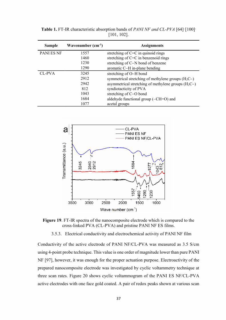
37
Sample Wavenumber (cm-1) Assignments
PANI ES NF 1557 stretching of C=C in quinoid rings
1460 stretching of C=C in benzenoid rings
1230 stretching of C−N bond of benzene
1290 aromatic C−H in-plane bending CL-PVA 3245 stretching of O−H bond
2912 symmetrical stretching of methylene groups (H2C−)
2942 asymmetrical stretching of methylene groups (H2C−)
812 syndiotacticity of PVA
1043 stretching of C−O bond
1684 aldehyde functional group (−CH=O) and
1077 acetal groups
3.5.3. Electrical conductivity and electrochemical activity of PANI NF film
Conductivity of the active electrode of PANI NF/CL-PVA was measured as 3.5 S/cm
using 4-point probe technique. This value is one order of magnitude lower than pure PANI
NF [97], however, it was enough for the proper actuation purpose. Electroactivity of the
prepared nanocomposite electrode was investigated by cyclic voltammetry technique at
three scan rates. Figure 20 shows cyclic voltammogram of the PANI ES NF/CL-PVA
active electrodes with one face gold coated. A pair of redox peaks shown at various scan
Table 1. FT-IR characteristic absorption bands of PANI NF and CL-PVA [64], [100],
[101, 102].
Figure 19. FT-IR spectra of the nanocomposite electrode which is compared to the
cross-linked PVA (CL-PVA) and pristine PANI NF ES films.

38
rates confirms the electroactivity of PANI ES NF film in 1 M HCl solution. Semi-porous
nature of the prepared electrode illustrated in SEM micrographs (Figure 18 a, b) allows
Clˉ counter ions to diffuse in/out easily during cycling in 1 M HCl solution which results
in high anodic and cathodic current. Reversibility of redox reactions in the PANI NF ES
nanocomposite film was also confirmed by linear relation of peak current vs square root
of scan rate (inset graph of Figure 20).
3.5.4. Actuation behavior of PANI NF film actuator
Bending stroke of the prepared composite actuator was characterized using our home-
made set-up. The mechanism of actuation is attributed to injection/rejection of acid
counterions together with solvent molecules to/from PANI chains which results in
expansion/contraction of the polymer [42]. As schematic in Figure 21 a depicts, when a
positive potential is applied to PANI, it is oxidized to a positively charged polymer. To
maintain neutral state, positive polymer backbone attracts negative ions (Clˉ counter ions
surrounded by water molecules) from surrounding media (CL-PVA gel electrolyte) which
results in swelling and expansion of polymer chains [8]. The opposite phenomenon
happens simultaneously at the negative electrode in which PANI reduces, rejects out
counter ions and thus the polymer contracts. In the next half cycle, oxidizing and reducing
electrodes are reversed and opposite stroke happens as a result. Cross section of the
prepared bending actuator without gold electrode is shown in Figure 21 b. Nanocomposite
actuator with a thickness of 28-30 has a semi-porous microstructure which creates
Figure 20. Cyclic voltammetry at three scan rates of 1, 5, 10 mV/s in 1M HCl. Gold
coating was applied on one side of the electrode. Inset graph illustrates corresponding
oxidation peak current vs. square root of scan rate which shows a linear behavior.

39
pathways for higher ion/solvent mobility and thus results in higher actuation stroke [103].
Since little amount of CL-PVA gel electrolyte is hot-pressed between two electrodes and
it is from the same type of electrode film matrix (CL-PVA) the electrolyte has diffused
and spread all over the porosities of electrodes during hot-pressing. Therefore,
homogenous film along the cross-section is formed in such a way that interface of
electrodes and gel electrolyte is not distinguishable. In Figure 21 c, d snapshots of
actuation strokes in the air are demonstrated from a recorded video clip.

40
Figure 22 shows the horizontal projection of tip movement of the actuator strip in 1 M
HCl solution versus time for various frequencies. The graphs compare the first 10 cycles
at each frequency. Since AC square voltage stimulation was used, in low frequencies
actuator is subject to the electrical field for longer times, and thus moves a longer distance.
Figure 21. (a) Schematic mechanism of actuation stroke of the prepared nanocomposite
bending actuator. (b) Cross section of the actuator without the gold electrode. The white
color on top of actuator film is reflection of light from nanocomposite actuator surface.
(c, d) Snapshots of the bending actuator strokes in the air.

41
In other words, with increasing frequency the total path that actuator can move in each
cycle decreases.
Figure 23 shows horizontal tip displacement of the actuator strip in the air. As it is seen
in Figure 23 a, actuation stroke decays from the first cycle and this decay is observed at
all frequencies. To better understand the deteriorating behavior of the actuator, life cycle
and stability were investigated under 0.5 V square wave potential at four frequencies (50,
100, 500, 1000 mHz) for at least 1000 s in both air and 1 M HCl solution.
Figure 22. Horizontal tip displacement of PANI ES NF/CL-PVA actuator under 1 M HCl
solution at various frequencies of; a) 50 mHz, b) 100 mHz, c) 500 mHz, d) 1000 mHz.

42
Figure 24 illustrates total displacement of the PANI NF composite actuator under 1M
HCl solution. At all frequencies, stable behavior was observed during scan interval of
1000 s. Since the actuator response was not necessarily symmetrical to the left and right,
for a better comparison, the total displacement of actuator tip in each cycle was measured
as a function of time (or cycle number) and reported in this set of graphs. The total
displacement of the PANI NF composite actuator at 50 mHz is about 22 mm which is
promising in comparison with the performance of reported pure PANI actuators at the
same voltage or frequency range [104, 105]. High actuation stroke of the PANI NFs is
attributed to porous microstructure made by high aspect ratio PANI NFs in active
electrodes (Figure 18) which facilitates ion diffusion [103].
However, the performance of the PANI NF actuator in air deteriorates with time as it is
shown in Figure 25 for all used frequencies. In this graph, since the data values in high-
frequency tests i.e. 500 and 1000 mHz, are scattered, an average curve was fit. The decay
of actuation stroke was attributed to evaporation of water from gel electrolyte in the air
which is expedited by applied electrical field due to Joule heating effect [106]. Final
Figure 23. Horizontal tip displacement of the PANI ES NF/CL-PVA actuator in the air
at various frequencies of: a) 50 mHz, b) 100 mHz, c) 500 mHz, d) 1000 mHz.

43
values of the total displacements for frequencies of 50, 100, 500, 1000 mHz are about
2.5, 0.3, 0.15, 0.05 mm, respectively.
In comparison with other air actuators reported in the state-of-the-art, which used PANI
or its composites to our knowledge, our actuator shows higher linear displacement (4.5
mm stroke) during first cycles in the air at similar test conditions (0.5V, 100 mHz).
Specifically, ≈0.25 mm and ≈0.5 mm displacements were reported for, respectively,
PANI and PANI/reduced graphene oxide nanocomposite by Liu et al. [56]. However,
after about 70 cycles, displacement of our actuator decays to under 0.5 mm due to water
evaporation from the actuator. The air-actuator could retain 16.67% of initial actuation
stroke after 1600 seconds of working in air at 50 mHz. At the same frequency of 10 mHz,
under higher voltage stimuli of 2 V, a displacement of ≈ 2 mm and a very high stability
is reported for non-PANI based air-working actuators such as for MWCNT and reduced
graphene oxide/MWCNT in the literature [107].
Figure 24. Total displacement of actuator tip in each cycle under 1 M HCl solution as a
function of time/cycle number at various of frequencies.

44
3.6. PVDF-g-PSSA actuator
3.6.1. Graft level (GL) and degree of sulfonation (DOS)
Radiation-induced grafting of PSSS on PVDF and its activation to PVDF-g-PSSA is
schematically shown in Figure 26. In the first step, γ-ray irradiation creates some active
radicals along the PVDF chains. Since binding energy of H to C is less than F to C, most
of the radicals are assumed to be formed by detaching the hydrogen atoms. In the next
step, as soon as the irradiated PVDF chains containing free radicals meet the monomer
polymerization starts, resulting in polystyrene sulfonate in side branches. As mentioned
before, the concentration of sulfuric acid has an essential role in controlling the graft level
of the product.
Figure 25. Total displacement of actuator tip in each cycle in the air as a function of
time/cycle number at various frequencies.

45
Graft level (GL) of radiation grafted polymer was quantified by the concentration of
H2SO4 used. Figure 27 a illustrates the effect of the H2SO4 concentration on GL of the
synthesized polymer. For the lower monomer concentration (PVDF/SSS=1:1) an
optimum H2SO4 concentration was 0.4 mol/L, while the optimum acid concentration for
the reaction with higher monomer concentration (PVDF/SSS=1:2) was achieved at 0.8
mol/L. Degree of sulfonation (DOS) of grafted polymers which is illustrated in Figure 27
b is consistent with the GL. Increasing the GL of grafted polymers, DOS increases as
well. For the rest of this work, graft levels of 19%, 29%, and 35% were selected and
named as G19, G29, and G35, respectively.
Figure 26. Schematic of graft polymerization method used in this work.

46
3.6.2. Structural characterization of PVDF-g-PSSA
To investigate graft polymerization of the polystyrene sulfonic acid on PVDF backbone,
FT-IR and 1H NMR characterizations were performed. FT-IR spectra of polymerized
samples at different GLs are shown in Figure 28. Characteristic peaks of sulfonic acid
group occur at around 1034 cm-1 (symmetric stretch of −SO3H) and 1650 cm-1 (stretching
vibration of benzene rings) [71, 94] which are shown in magnified graphs of Figure 28 b
and Figure 28 c, respectively. The broad peak around 3420 cm-1 (Figure 28 a) is attributed
to water absorption of sulfonic groups. It is notable that intensity of all mentioned peaks
depends on the concentration of sulfonic acid groups and increases with GL especially
from G19 to G29.
1H NMR spectra of synthesized grafted polymers are depicted in Figure 29. The peaks at
2.5 and 3.4 ppm correspond to solvent (DMSO) and water, respectively. The peaks of
head-to-tail and head-to-head bonding arrangements of PVDF appeared at 2.9 and 2.3
ppm, respectively [108]. The peaks at 6.5 and 7.5 ppm in all grafted polymers were
attributed to PSSS side branch [108], as they are shown in the structure schematic in
Figure 29. This data confirms FT-IR results which indicate successful and controlled graft
polymerization of PSSS on PVDF.
Figure 27. (a) Dependency of the graft level on sulfuric acid concentration as the main
grafting parameter. (b) Degree of sulfonation based on IEC for different grafted
polymers.
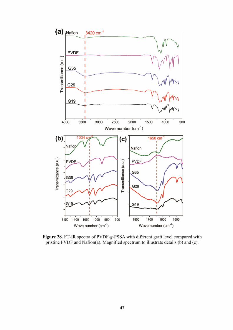
47
Figure 28. FT-IR spectra of PVDF-g-PSSA with different graft level compared with
pristine PVDF and Nafion(a). Magnified spectrum to illustrate details (b) and (c).

48
3.6.3. Morphology of PVDF-g-PSSA membranes
Morphology of surface and cross-section of the PVDF-g-PSSA IPMC actuators were
investigated before and after Pt plating (Figure 30). As Figure 30 a,b illustrate, surface
morphology of G35 membrane before Pt plating is dominated by porosities. For this
reason, abrasion of the PVDF-g-PSSA membranes before ion exchange process was
skipped. This porosity rich microstructure also enhances WU and conductivity of the
membranes which can be expected to result in higher actuation strokes [109, 110]. In
addition, such a porous microstructure facilitates deeper diffusion of Pt salt into the
membrane. As a consequence, only one reduction step suffices for the formation of a
continuous and effective electrode which requires two or three reduction times for other
reported IPMC actuators membranes [71, 94]. Figure 30 c,d depict G35 IPMC actuator
Figure 29. 1H NMR spectrum of grafted polymers compared with pristine PVDF.

49
surface after electroless Pt plating. As it can be clearly seen from the images, the entire
surface is completely covered with Pt particles in such a way that surface porosity is no
longer visible in micrographs. Figure 30 e shows the cross-section of G35 IPMC actuator
after Pt plating. EDS line scan elemental analysis results for Pt, S, and F along the red
arrow is illustrated in Figure 30 f.
Accordingly, sulfur and fluorine show uniform dispersion through the thickness, while Pt
accumulated near the surface of the membranes without deep penetration into the bulk of
Figure 30. SEM micrographs of prepared G35 IPMC actuator before Pt electroless plating
(a,b) and after electroless plating (c,d). cross-section of plated G35 IPMC actuator (e). The
red arrow depicts EDS line scan along with cross section. (f) shows elemental line scan
analysis curves for Pt, S, and F along with the red arrow shown in (e).

50
the membrane which substantiates successful electroplating procedure. From Figure 30 f,
depth of Pt penetration as electrode thickness can be approximated about 15-20 .
3.6.4. Thermogravimetric characterization of PVDF-g-PSSA membrane
Thermogravimetric behavior of the grafted polymers as well as pristine PVDF from room
temperature to 800 °C is shown in Figure 31. For all samples, three weight loss steps can
be noted as also reported earlier for radiation grafted membranes [111]. The first step
which occurs about 70-150 °C corresponds to evaporation of water molecules absorbed
due to hydrophilic sulfonic acid groups. The second step of the weight loss at about 250-
380 °C is attributed to the decomposition of sulfonic acid groups. The main weight loss
which is similar to pristine PVDF occurs at 420-500 °C due to degradation of the PVDF
backbone. The weight loss above 550 °C ascribed to decomposition of the PVDF chain.
3.6.5. Mechanical characterization of PVDF-g-PSSA membranes
Mechanical properties of PVDF-g-PSSA membranes, as well as Nafion membrane, were
investigated by tensile tests in dry and wet states. As Figure 32 a illustrates, tensile
modulus of the grafted membranes decreases with GL in the dry state. The reason is
ascribed to the absorbed water molecules due to sulfonic acid groups which act as
Figure 31. Thermogravimetric curves of prepared graft copolymers as well as pristine
PVDF.

51
plasticizer [112]. Such an effect can also be seen in the tensile strength of the grafted
membranes in the dry state. It is notable that radiation grafted membranes’ tensile
modulus in the dry state is much higher than the Nafion due to the rigidity of high
molecular weight PVDF backbone in the grafted membranes. This feature is reported for
other radiation grafted membranes as well [113]. However, the tensile strength of Nafion
(Figure 32 b) is in the same range with that of the grafted membranes. It is remarkable
that tensile strength and modulus of membrane G19 which has lower GL in the wet state
is slightly lower than its dry state while for membranes of G29 and G35 they are at least
2-fold less. This is can also be attributed to the plasticizing effect of water molecules
attached to sulfonic acid groups [112]. Generally, low tensile modulus facilitates higher
bending displacement, so membranes of G29 and G35 can be considered promising
candidates for making bending actuator in the wet state.
3.6.6. Physical properties of PVDF-g-PSSA membranes
Physical properties of the radiation grafted membranes and Nafion including IEC, WU,
and proton conductivity are compared in Figure 33. As expected, with GL increasing, the
properties reported increase because of increasing number of sulfonic acid groups. On the
other hand, Nafion shows high IEC and therefore high conductivity almost as high as G35
membrane with highest graft level.
Note that the membrane with highest graft level (G35) shows IEC (1 mmol/g) and proton
conductivity (82 mS/cm) almost as high as Nafion. These two properties are crucial for
application of our membranes as IPMC actuators. It is considerable that membrane G35
exhibits near 3 times greater WU (62 wt. %) than the Nafion, but their conductivities are
Figure 32. Tensile modulus (a), and Tensile strength (b), of the prepared membrane in
dry and wet states, compared with Nafion.
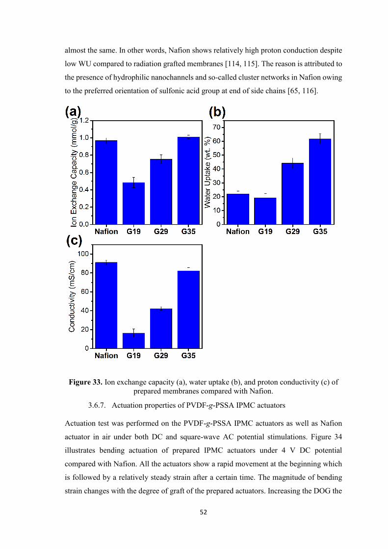
52
almost the same. In other words, Nafion shows relatively high proton conduction despite
low WU compared to radiation grafted membranes [114, 115]. The reason is attributed to
the presence of hydrophilic nanochannels and so-called cluster networks in Nafion owing
to the preferred orientation of sulfonic acid group at end of side chains [65, 116].
3.6.7. Actuation properties of PVDF-g-PSSA IPMC actuators
Actuation test was performed on the PVDF-g-PSSA IPMC actuators as well as Nafion
actuator in air under both DC and square-wave AC potential stimulations. Figure 34
illustrates bending actuation of prepared IPMC actuators under 4 V DC potential
compared with Nafion. All the actuators show a rapid movement at the beginning which
is followed by a relatively steady strain after a certain time. The magnitude of bending
strain changes with the degree of graft of the prepared actuators. Increasing the DOG the
Figure 33. Ion exchange capacity (a), water uptake (b), and proton conductivity (c) of
prepared membranes compared with Nafion.
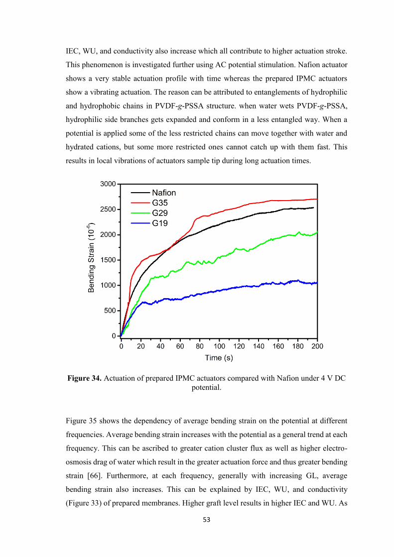
53
IEC, WU, and conductivity also increase which all contribute to higher actuation stroke.
This phenomenon is investigated further using AC potential stimulation. Nafion actuator
shows a very stable actuation profile with time whereas the prepared IPMC actuators
show a vibrating actuation. The reason can be attributed to entanglements of hydrophilic
and hydrophobic chains in PVDF-g-PSSA structure. when water wets PVDF-g-PSSA,
hydrophilic side branches gets expanded and conform in a less entangled way. When a
potential is applied some of the less restricted chains can move together with water and
hydrated cations, but some more restricted ones cannot catch up with them fast. This
results in local vibrations of actuators sample tip during long actuation times.
Figure 35 shows the dependency of average bending strain on the potential at different
frequencies. Average bending strain increases with the potential as a general trend at each
frequency. This can be ascribed to greater cation cluster flux as well as higher electro-
osmosis drag of water which result in the greater actuation force and thus greater bending
strain [66]. Furthermore, at each frequency, generally with increasing GL, average
bending strain also increases. This can be explained by IEC, WU, and conductivity
(Figure 33) of prepared membranes. Higher graft level results in higher IEC and WU. As
Figure 34. Actuation of prepared IPMC actuators compared with Nafion under 4 V DC
potential.

54
a result, proton conductivity enhances which finally gives rise to increase in cation and
water accumulation in actuator cathode, hence bending strain surges. In comparison with
Nafion, the PVDF-g-PSSA based IPMC actuator with the highest graft level (G35) shows
superior average bending actuation in low frequency (0.1 Hz) and higher voltages (4 V).
Figure 36 depicts frequency dependency of actuation bending strain for various IPMC
actuators with different graft levels. As it can be seen in all graphs, average bending strain
decreases with increasing frequency which is a typical behavior of the IPMC actuators.
In higher frequencies, the actuator has a shorter time to comply with potential stimulation
thus exhibits smaller displacements. Another point which can be noted in Figure 36 is
that at each frequency average bending increases with potential which is consistent with
Figure 35. Average bending strain versus voltage for prepared IPMC actuators at (a)
0.1 Hz, (b) 0.5 Hz and (c) 1 Hz. (d) comparison of various frequencies for 35% graft
IPMC actuator.

55
Figure 35. Figure 36 e compares average bending strain of different IPMC actuators with
different graft degree at highest potential of 4V. IPMC actuator G35 shows highest
average bending actuation which can be explained according to its higher graft level and
therefore higher IEC and conductivity together with low tensile modulus in the wet state.
To demonstrate the progressive variation of the actuation strain (not average strain) with
applied square-wave potential, in Figure 37 bending strain versus time is shown at the
highest average bending conditions for our best IPMC actuator (G35) (0.1 Hz, 4 V, in
Figure 35 and Figure 36). As shown in Figure 37 a-c, PVDF-g-PSSA based IPMC
actuators can function in sync with periodically changing excitation voltage, which
Figure 36. Average bending strain versus frequency for prepared IPMC actuators for
various graft levels of (a) G19, (b) G29, (c) G35, (d) Nafion. (e) comparison of all
prepared IPMC actuators at highest potential of 4 V.

56
indicates the robustness of actuators as well as the successful integration of electrode-
membrane.
Actuation stroke of our most prosperous IPMC actuator (G35) is visually demonstrated
also under DC potential. Several successive snapshots taken during actuation stroke at
different times are shown in Figure 38. Bending strain and curvature of the actuator
increased, after 35 seconds of constant 4 V, the bending strain was in excess of 2825 x
10-6 with bending angle of 136 degrees.
Figure 37. Bending strain as a function of time for selected conditions of (a) 4 V, 0.1
Hz. (b) 4 V, G35. (c) G35, 0.1 Hz. (d) Illustrates potential-time square-wave form
which is used to stimulate IPMC actuators.

57
4. Conclusions
In this thesis, two different actuators based on electroactive polymers were designed,
successfully fabricated and characterized. In the first part of the study, electroactuation
of polyaniline nanofibers-based nanocomposite actuator was investigated in air and in 1
M HCl solution. Mildly CL-PVA hydrogel was added to PANI NFs to make it pliable
and used also as gel electrolyte to provide ions during actuation. According to SEM
micrographs and cyclic voltammetry characterizations, the porous microstructure of
PANI NF film enhanced fast ion diffusion. At the initial cycles of the actuation in the air,
stroke as high as 7 mm is observed that makes the total displacement of 15 mm. However,
general performance of actuator decayed due to draining water from PVA gel electrolyte.
The air-actuator could retain 16.67% of initial actuation stroke after 1600 s of working in
air at 50 mHz. Displacement of the strip actuator by a voltage stimulus as low as 0.5 V
under solution showed stable and repeatable results. High actuation stroke PANI NFs was
attributed to the microporous structure of active electrode made from high aspect ratio
PANI NFs.
In the second part of the study, a novel method was exploited for directly grafting of
PSSA onto PVDF which is simple and fast. In this way, PVDF-g-PSSA with three graft
levels were successfully synthesized. Membranes were cast from synthesized graft
polymer solutions. IEC, WU and conductivity measurements of PVDF-g-PSSA
Figure 38. Successive snapshots of G35 IPMC actuator during actuation at 4 V DC
potential in the air.

58
membranes showed an increase with the increase of graft level. In this respect, IEC, WU
and proton conductivity of our most prosperous membrane (G35) were 1 mmol/g, 62
wt.% and 82 S/cm, respectively. To make an IPMC actuator, membranes were Pt
electroded by electroless plating method and their actuation performance was investigated
in the air. For comparison, Nafion membrane was also electroless plated and tested. To
the best of our knowledge, the PVDF-g-PSSA was demonstrated as an IPMC actuator for
the first time. With the highest graft level (G35), it showed the highest performance in
terms of average bending strain (920x10-6) among other ones in frequency of 0.1 Hz and
potential of 4 V. The results reported herein suggest that PVDF-g-PSSA can be a
promising candidate for Nafion in many applications as soft actuator and sensor due to
its simple and cheap preparation procedure.

59
5. References
1. H. Shirakawa, et al., Synthesis of electrically conducting organic polymers: Halogen derivatives of polyacetylene, (ch). Journal of the Chemical Society, Chemical Communications, 1977(16): p. 578-580.
2. A.G. Macdiarmid, Synthetic metals: A novel role for organic polymers. Synthetic Metals, 2001. 125(1): p. 11-22.
3. K.M. Molapo, et al., Electronics of conjugated polymers (i): Polyaniline. International Journal of Electrochemical Science, 2012. 7(12): p. 11859 - 11875.
4. E.M. Geniès, et al., Polyaniline: A historical survey. Synthetic Metals, 1990. 36(2): p. 139-182.
5. W.-S. Huang, B.D. Humphrey, and A.G. Macdiarmid, Polyaniline, a novel conducting polymer. Morphology and chemistry of its oxidation and reduction in aqueous electrolytes. Journal of the Chemical Society, Faraday Transactions 1: Physical Chemistry in Condensed Phases, 1986. 82(8): p. 2385-2400.
6. A.G. Macdiarmid, et al., Polyaniline - interconversion of metallic and insulating forms. Molecular Crystals and Liquid Crystals, 1985. 121(1-4): p. 173-180.
7. S. Stafstrom, et al., Polaron lattice in highly conducting polyaniline - theoretical and optical studies. Physical Review Letters, 1987. 59(13): p. 1464-1467.
8. E. Smela, W. Lu, and B.R. Mattes, Polyaniline actuators: Part 1. Pani(amps) in hcl. Synthetic Metals, 2005. 151(1): p. 25-42.
9. A.J. Heeger, Semiconducting and metallic polymers: The fourth generation of polymeric materials. The Journal of Physical Chemistry B, 2001. 105(36): p. 8475-8491.
10. S. Tawde, D. Mukesh, and J.V. Yakhmi, Redox behavior of polyaniline as influenced by aromatic sulphonate anions: Cyclic voltammetry and molecular modeling. Synthetic Metals, 2001. 125(3): p. 401-413.
11. A.G. Macdiarmid, “Synthetic metals”: A novel role for organic polymers (nobel lecture). Angewandte Chemie International Edition, 2001. 40(14): p. 2581-2590.
12. I. Sapurina and J. Stejskal, The mechanism of the oxidative polymerization of aniline and the formation of supramolecular polyaniline structures. Polymer International, 2008. 57(12): p. 1295-1325.
13. P.N. Adams, D.C. Apperley, and A.P. Monkman, A comparison of the molecular weights of polyaniline samples obtained from gel permeation chromatography and solid state 15n n.M.R. Spectroscopy. Polymer, 1993. 34(2): p. 328-332.
14. A.M. Kenwright, et al., Solution-state carbon-13 nuclear magnetic resonance studies of polyaniline. Polymer, 1992. 33(20): p. 4292-4298.
15. G.G. Wallace, et al., Conductive electroactive polymers: Intelligent polymer systems : Intelligent materials systems. 2nd Edition ed. 2003, Boca Raton, Florida: CRC Press LLC.
16. L.H.C. Mattoso, A.G. Macdiarmid, and A.J. Epstein, Controlled synthesis of high molecular weight polyaniline and poly(o-methoxyaniline). Synthetic Metals, 1994. 68(1): p. 1-11.
17. V. Gupta and N. Miura, High performance electrochemical supercapacitor from electrochemically synthesized nanostructured polyaniline. Materials Letters, 2006. 60(12): p. 1466-1469.
18. F.M. Kelly, et al., Polyaniline: Application as solid state electrochromic in a flexible textile display. Displays, 2013. 34(1): p. 1-7.
19. Y. Qiao, et al., Carbon nanotube/polyaniline composite as anode material for microbial fuel cells. Journal of Power Sources, 2007. 170(1): p. 79-84.
20. C.-H. Chang, et al., Novel anticorrosion coatings prepared from polyaniline/graphene composites. Carbon, 2012. 50(14): p. 5044-5051.

60
21. M.R. Anderson, et al., Conjugated polymer films for gas separations. Science, 1991. 252(5011): p. 1412-5.
22. J.X. Huang, et al., Polyaniline nanofibers: Facile synthesis and chemical sensors. Journal of the American Chemical Society, 2003. 125(2): p. 314-315.
23. K. Kaneto, et al., Artificial muscle - electromechanical actuators using polyaniline films. Synthetic Metals, 1995. 71(1-3): p. 2211-2212.
24. H.D. Tran, et al., Toward an understanding of the formation of conducting polymer nanofibers. ACS Nano, 2008. 2(9): p. 1841-1848.
25. D. Li, J.X. Huang, and R.B. Kaner, Polyaniline nanofibers: A unique polymer nanostructure for versatile applications. Accounts of Chemical Research, 2009. 42(1): p. 135-145.
26. J. Huang and R.B. Kaner, Nanofiber formation in the chemical polymerization of aniline: A mechanistic study. Angewandte Chemie International Edition, 2004. 43(43): p. 5817-5821.
27. J. Huang and R.B. Kaner, The intrinsic nanofibrillar morphology of polyaniline. Chemical Communications, 2006(4): p. 367-376.
28. D. Li and R.B. Kaner, Shape and aggregation control of nanoparticles: Not shaken, not stirred. Journal of the American Chemical Society, 2006. 128(3): p. 968-975.
29. D. Li and R.B. Kaner, How nucleation affects the aggregation of nanoparticles. Journal of Materials Chemistry, 2007. 17(22): p. 2279-2282.
30. I.Y. Sapurina and M.A. Shishov, Oxidative polymerization of aniline: Molecular synthesis of polyaniline and the formation of supramolecular structures, in New polymers for special applications, D.A.D.S. Gomes, Editor. 2012, InTech.
31. Y. Sonoda, W. Takashima, and K. Kaneto, Characteristics of soft actuators based on polypyrrole films. Synthetic Metals, 2001. 119(1–3): p. 267-268.
32. M. Kaneko and K. Kaneto, Electrochemornechanical deformation in polyaniline and poly(o-methoxyaniline). Synthetic Metals, 1999. 102(1): p. 1350-1353.
33. H. Varela and R.M. Torresi, Ionic exchange phenomena related to the redox processes of polyaniline in nonaqueous media. Journal of The Electrochemical Society, 2000. 147(2): p. 665-670.
34. G. Horányi and G. Inzelt, Anion-involvement in electrochemical transformations of polyaniline. A radiotracer study. Electrochimica Acta, 1988. 33(7): p. 947-952.
35. S. Pruneanu, et al., Electrochemical quartz crystal microbalance study of the influence of the solution composition on the behaviour of poly(aniline) electrodes. Electrochimica Acta, 1998. 43(16): p. 2305-2323.
36. E. Song and J.-W. Choi, Conducting polyaniline nanowire and its applications in chemiresistive sensing. Nanomaterials, 2013. 3(3): p. 498.
37. A.H. Saheb and S.S. Seo, Uv-vis and raman spectral analysis of polyaniline/gold thin films as a function of applied potential. Analytical Letters, 2011. 44(7): p. 1206-1216.
38. J. Zhou, et al., High-ampacity conductive polymer microfibers as fast response wearable heaters and electromechanical actuators. Journal of Materials Chemistry C, 2016. 4(6): p. 1238-1249.
39. S. Niamlang and A. Sirivat, Dielectrophoresis force and deflection of electroactive poly(p-phenylene vinylene)/polydimethylsiloxane blends. Smart Materials & Structures, 2008. 17(3).
40. T.F. Otero, et al., Electrochemomechanical properties from a bilayer: Polypyrrole / non-conducting and flexible material — artificial muscle. Journal of Electroanalytical Chemistry, 1992. 341(1): p. 369-375.
41. P.A. Anquetil, et al., Thiophene-based conducting polymer molecular actuators, in Smart structures and materials 2002: Electroactive polymer actuators and devices, Y. BarCohen, Editor. 2002, Spie-Int Soc Optical Engineering: Bellingham. p. 424-434.

61
42. W. Takashima, et al., The electrochemical actuator using electrochemically-deposited poly-aniline film. Synthetic Metals, 1995. 71(1–3): p. 2265-2266.
43. W. Lu and B.R. Mattes, Electrochemical behavior and electromechanical actuation of pani in nonaqueous electrolytes. Journal of The Electrochemical Society, 2003. 150(9): p. E416-E422.
44. W. Lu, et al., Development of solid-in-hollow electrochemical linear actuators using highly conductive polyaniline. Chemistry of Materials, 2004. 16(9): p. 1615-1621.
45. H. Gao, et al., Monolithic polyaniline/polyvinyl alcohol nanocomposite actuators with tunable stimuli-responsive properties. Sensors and Actuators B: Chemical, 2010. 145(2): p. 839-846.
46. Y.A. Ismail, et al., Electrochemical actuation in chitosan/polyaniline microfibers for artificial muscles fabricated using an in situ polymerization. Sensors and Actuators B: Chemical, 2008. 129(2): p. 834-840.
47. Y.-Z. Long, et al., Recent advances in synthesis, physical properties and applications of conducting polymer nanotubes and nanofibers. Progress in Polymer Science, 2011. 36(10): p. 1415-1442.
48. D. Li, J. Huang, and R.B. Kaner, Polyaniline nanofibers: A unique polymer nanostructure for versatile applications. Accounts of chemical research, 2008. 42(1): p. 135-145.
49. C.O. Baker, et al., Monolithic actuators from flash-welded polyaniline nanofibers. Advanced Materials, 2008. 20(1): p. 155-158.
50. Z.D. Zujovic, et al., Structure of ultralong polyaniline nanofibers using initiators. Macromolecules, 2011. 44(8): p. 2735-2742.
51. X. Zhang, W.J. Goux, and S.K. Manohar, Synthesis of polyaniline nanofibers by “nanofiber seeding”. Journal of the American Chemical Society, 2004. 126(14): p. 4502-4503.
52. M. Bhaumik, R.I. Mccrindle, and A. Maity, Enhanced adsorptive degradation of congo red in aqueous solutions using polyaniline/fe0 composite nanofibers. Chemical Engineering Journal, 2015. 260: p. 716-729.
53. J. Huang and R.B. Kaner, A general chemical route to polyaniline nanofibers. Journal of the American Chemical Society, 2004. 126(3): p. 851-855.
54. H.D. Tran, D. Li, and R.B. Kaner, One-dimensional conducting polymer nanostructures: Bulk synthesis and applications. Advanced Materials, 2009. 21(14-15): p. 1487-1499.
55. K. Kaneto, et al., “Artificial muscle”: Electromechanical actuators using polyaniline films. Synthetic Metals, 1995. 71(1–3): p. 2211-2212.
56. Q. Liu, et al., Synergistic effect of a r-go/pani nanocomposite electrode based air working ionic actuator with a large actuation stroke and long-term durability. Journal of Materials Chemistry A, 2015. 3(16): p. 8380-8388.
57. S.D. Deshpande, et al. Actuation behavioral studies on polyaniline-cellophane based electroactive paper. 2005.
58. W. Lu, et al., Use of ionic liquids for pi-conjugated polymer electrochemical devices. Science, 2002. 297(5583): p. 983-987.
59. W. Lu and B.R. Mattes, Factors influencing electrochemical actuation of polyaniline fibers in ionic liquids. Synthetic Metals, 2005. 152(1): p. 53-56.
60. F. Vidal, et al., Long-life air working conducting semi-ipn/ionic liquid based actuator. Synthetic Metals, 2004. 142(1-3): p. 287-291.
61. I. Must, et al., Ionic liquid-based actuators working in air: The effect of ambient humidity. Sensors and Actuators B: Chemical, 2014. 202: p. 114-122.
62. M. Amde, J.F. Liu, and L. Pang, Environmental application, fate, effects, and concerns of ionic liquids: A review. Environmental Science & Technology, 2015. 49(21): p. 12611-12627.
62
63. X. Wang, et al., High flux filtration medium based on nanofibrous substrate with hydrophilic nanocomposite coating. Environmental Science & Technology, 2005. 39(19): p. 7684-7691.
64. K.C.S. Figueiredo, T.L.M. Alves, and C.P. Borges, Poly(vinyl alcohol) films crosslinked by glutaraldehyde under mild conditions. Journal of Applied Polymer Science, 2009. 111(6): p. 3074-3080.
65. S. Mohsen and J.K. Kwang, Ionic polymer-metal composites: I. Fundamentals. Smart Materials and Structures, 2001. 10(4): p. 819.
66. J.H. Lee, et al., Water uptake and migration effects of electroactive ion-exchange polymer metal composite (ipmc) actuator. Sensors and Actuators A: Physical, 2005. 118(1): p. 98-106.
67. J.K. Kwang and S. Mohsen, Ionic polymer–metal composites: Ii. Manufacturing techniques. Smart Materials and Structures, 2003. 12(1): p. 65.
68. R. Tiwari and E. Garcia, The state of understanding of ionic polymer metal composite architecture: A review. Smart Materials and Structures, 2011. 20(8): p. 083001.
69. C. Jo, et al., Recent advances in ionic polymer–metal composite actuators and their modeling and applications. Progress in Polymer Science, 2013. 38(7): p. 1037-1066.
70. Y. Joanne, et al., Experimentally validated improvement of ipmc performance through alternation of pretreatment and electroless plating processes. Smart Materials and Structures, 2011. 20(1): p. 015009.
71. Y. Tang, et al., Novel sulfonated polysulfone ion exchange membranes for ionic polymer–metal composite actuators. Sensors and Actuators B: Chemical, 2014. 202: p. 1164-1174.
72. S. Nemat-Nasser, Micromechanics of actuation of ionic polymer-metal composites. Journal of Applied Physics, 2002. 92(5): p. 2899-2915.
73. S. Nemat-Nasser and Y. Wu, Comparative experimental study of ionic polymer–metal composites with different backbone ionomers and in various cation forms. Journal of Applied Physics, 2003. 93(9): p. 5255-5267.
74. M.M. Nasef, et al., Radiation-grafted materials for energy conversion and energy storage applications. Progress in Polymer Science, 2016. 63(Supplement C): p. 1-41.
75. S. Alkan Gürsel, et al., Radiation grafted membranes, in Fuel cells i, G.G. Scherer, Editor. 2008, Springer Berlin Heidelberg: Berlin, Heidelberg. p. 157-217.
76. J.A. Horsfall and K.V. Lovell, Synthesis and characterisation of sulfonic acid-containing ion exchange membranes based on hydrocarbon and fluorocarbon polymers. European Polymer Journal, 2002. 38(8): p. 1671-1682.
77. S. Mohsen and J.K. Kwang, Ionic polymer–metal composites: Iv. Industrial and medical applications. Smart Materials and Structures, 2005. 14(1): p. 197.
78. S.A. Wilson, et al., New materials for micro-scale sensors and actuators: An engineering review. Materials Science and Engineering: R: Reports, 2007. 56(1): p. 1-129.
79. H.Y. Jeong and B.K. Kim, Electrochemical behavior of a new type of perfluorinated carboxylate membrane/platinum composite. Journal of Applied Polymer Science, 2006. 99(5): p. 2687-2693.
80. J.Y. Lee, et al., Radiation-grafted fluoropolymers soaked with imidazolium-based ionic liquids for high-performance ionic polymer–metal composite actuators. Macromolecular Rapid Communications, 2010. 31(21): p. 1897-1902.
81. J.Y. Lee, et al., Performance enhancement of ionic polymer-metal composite actuators based on radiation-grafted poly(ethylene-co-tetrafluoroethylene). Macromolecular Research, 2011. 19(10): p. 1014.
82. M.J. Han, et al., Ionic polymer-metal composite actuators employing radiation-grafted fluoropolymers as ion-exchange membranes. Macromolecular Rapid Communications, 2006. 27(3): p. 219-222.

63
83. T.R. Dargaville, et al., High energy radiation grafting of fluoropolymers. Progress in Polymer Science, 2003. 28(9): p. 1355-1376.
84. L. Gubler, S.A. Gürsel, and G.G. Scherer, Radiation grafted membranes for polymer electrolyte fuel cells. Fuel Cells, 2005. 5(3): p. 317-335.
85. S. Sadeghi, et al., Enhancing proton conductivity via sub-micron structures in proton conducting membranes originating from sulfonated pvdf powder by radiation-induced grafting. Solid State Ionics, 2018. 314: p. 66-73.
86. G.B. Guo, E.D. Han, and S.L. An, Preparation and characterization of modified pvdf-g-pssa membrane, in New materials and advanced materials, pts 1 and 2, Z.Y. Jiang, J.T. Han, and X.H. Liu, Editors. 2011, Trans Tech Publications Ltd: Durnten-Zurich. p. 44-+.
87. L.F. Li, et al., A novel approach to prepare proton exchange membranes from fluoropolymer powder by pre-irradiation induced graft polymerization. Journal of Membrane Science, 2010. 346(1): p. 113-120.
88. C. Li, et al., Synthesis of pvdf-g-pssa proton exchange membrane by ozone-induced graft copolymerization and its application in microbial fuel cells. Journal of Membrane Science, 2017. 527: p. 35-42.
89. Y.H. Su, et al., The effect of side chain architectures on the properties and proton conductivities of poly(styrene sulfonic acid) graft poly(vinylidene fluoride) copolymer membranes for direct methanol fuel cells. Journal of Membrane Science, 2010. 349(1-2): p. 244-250.
90. V. Panwar, et al., New ionic polymer-metal composite actuators based on pvdf/pssa/pvp polymer blend membrane. Polymer Engineering and Science, 2011. 51(9): p. 1730-1741.
91. V. Panwar, et al., High actuation response of pvdf/pvp/pssa based ionic polymer metal composites actuator. Sensors and Actuators B-Chemical, 2012. 161(1): p. 460-470.
92. V. Panwar, et al., Enhanced and fast actuation of fullerenol/pvdf/pvp/pssa based ionic polymer metal composite actuators. Sensors and Actuators B-Chemical, 2013. 183: p. 504-517.
93. L. Unnikrishnan, et al., Polyethersulfone membranes: The effect of sulfonation on the properties. Polymer-Plastics Technology and Engineering, 2010. 49(14): p. 1419-1427.
94. Y. Tang, et al., The enhanced actuation response of an ionic polymer-metal composite actuator based on sulfonated polyphenylsulfone. Polymer Chemistry, 2014. 5(20): p. 6097-6107.
95. B.J. Akle, M.D. Bennett, and D.J. Leo, High-strain ionomeric–ionic liquid electroactive actuators. Sensors and Actuators A: Physical, 2006. 126(1): p. 173-181.
96. J. Lu, et al., A biomimetic actuator based on an ionic networking membrane of poly(styrene-alt-maleimide)-incorporated poly(vinylidene fluoride). Advanced Functional Materials, 2008. 18(8): p. 1290-1298.
97. J. Qiang, et al., Polyaniline nanofibers synthesized by rapid mixing polymerization. Synthetic Metals, 2008. 158(13): p. 544-547.
98. B. Silwana, et al., Inhibitive determination of metal ions using a horseradish peroxidase amperometric biosensor, in State of the art in biosensors - environmental and medical applications, T. Rinken, Editor. 2013, InTech: Rijeka. p. Ch. 05.
99. W. Hong, et al., Evidence of counterion migration in ionic polymer actuators via investigation of electromechanical performance. Sensors and Actuators B: Chemical, 2014. 205: p. 371-376.
100. S. Ashokan, V. Ponnuswamy, and P. Jayamurugan, Fabrication and characterization pani/cuo hybrid films by nebulizer spray pyrolysis technique for diode applications. Optik - International Journal for Light and Electron Optics, 2015. 126(20): p. 2591-2595.
101. D.S. Patil, et al., Chemical synthesis of highly stable pva/pani films for supercapacitor application. Materials Chemistry and Physics, 2011. 128(3): p. 449-455.

64
102. M. Trchová and J. Stejskal, Polyaniline: The infrared spectroscopy of conducting polymer nanotubes (iupac technical report). Pure and Applied Chemistry, 2011. 83(10): p. 1803-1817.
103. Y.A. Ismail, M.K. Shin, and S.J. Kim, A nanofibrous hydrogel templated electrochemical actuator: From single mat to a rolled-up structure. Sensors and Actuators B: Chemical, 2009. 136(2): p. 438-443.
104. A. Khan, Inamuddin, and R.K. Jain, Easy, operable ionic polymer metal composite actuator based on a platinum-coated sulfonated poly(vinyl alcohol)–polyaniline composite membrane. Journal of Applied Polymer Science, 2016. 133(33): p. n/a-n/a.
105. S.H. Kim, K.W. Oh, and J.H. Choi, Preparation and self-assembly of polyaniline nanorods and their application as electroactive actuators. Journal of Applied Polymer Science, 2010. 116(5): p. 2601-2609.
106. B. Cetin and D. Li, Effect of joule heating on electrokinetic transport. Electrophoresis, 2008. 29(5): p. 994-1005.
107. L. Lu, et al., Highly stable air working bimorph actuator based on a graphene nanosheet/carbon nanotube hybrid electrode. Advanced Materials, 2012. 24(31): p. 4317-4321.
108. Y.W. Kim, et al., Single-step synthesis of proton conducting poly(vinylidene fluoride) (pvdf) graft copolymer electrolytes. European Polymer Journal, 2008. 44(3): p. 932-939.
109. S.Y. Jung, et al., Enhanced ionic polymer-metal composite actuator with pore size-controlled porous nafion membrane using silica sol-gel process. Journal of Intelligent Material Systems and Structures, 2017. 28(11): p. 1514-1523.
110. D.X. Zhao, et al., Large deformation ionic polymer-metal composites actuators based on porous nafion membranes, in Electroactive polymer actuators and devices, Y. BarCohen and F. Vidal, Editors. 2016, Spie-Int Soc Optical Engineering: Bellingham.
111. S.A. Gürsel, et al., Thermal properties of proton-conducting radiation-grafted membranes. Journal of Applied Polymer Science, 2008. 108(6): p. 3577-3585.
112. E. Sgreccia, et al., Mechanical properties of proton-conducting sulfonated aromatic polymer membranes: Stress–strain tests and dynamical analysis. Journal of Power Sources, 2010. 195(23): p. 7770-7775.
113. H. Ben Youcef, et al., Influence of radiation-induced grafting process on mechanical properties of etfe-based membranes for fuel cells. Fuel Cells, 2010. 10(3): p. 401-410.
114. L. Gubler, et al., Proton exchange membranes prepared by radiation grafting of styrene/divinylbenzene onto poly(ethylene-alt-tetrafluoroethylene) for low temperature fuel cells. Solid State Ionics, 2005. 176(39): p. 2849-2860.
115. S. Alkan Gürsel, et al., Radiation-grafted membranes using a trifluorostyrene derivative. Journal of The Electrochemical Society, 2006. 153(10): p. A1964-A1970.
116. K.A. Mauritz and R.B. Moore, State of understanding of nafion. Chemical Reviews, 2004. 104(10): p. 4535-4586.