BEHAVIOUR OF A MODEL MV PILE IN SAND BEARING CAPACITY ...
43
BEHAVIOUR OF A MODEL MV PILE IN SAND BEARING CAPACITY IMPLICATIONS JOHN EVELYN GUY A dissertation submitted to the Faculty of Engineering, University of the Witwatersrand, Johannesburg, in fulfilment of the requirements for the Degree of Master of Science in Engineering. O JOHANNESBURG, 198 7
Transcript of BEHAVIOUR OF A MODEL MV PILE IN SAND BEARING CAPACITY ...
BEHAVIOUR OF A MODEL MV PILE IN SAND
BEARING CAPACITY IMPLICATIONS
JOHN EVELYN GUY
A dissertation submitted to the Faculty of Engineering,
University of the Witwatersrand, Johannesburg, in
fulfilment of the requirements for the Degree of Master
of Science in Engineering.
O
JOHANNESBURG, 198 7
DECLARATION
I declare that this dissertation is my own, unaided work.
It is being submitted for the Degree of Master of Science
in Engineering in the University of the Witwaterz: and.
Johannesburg. It has not been submitted before tor r 4
degree or examination in any other University.
(Signature of Candidate)
~7~n day of o & r~n 19»

(iii)
ABSTRACT
This report presents the results of a model MV pile test
conducted in ‘-.he laboratory and provides data on
measurements of the displacement of sand around the base
of the pile, as veil as o^ the loud distribution down
the pile during testing and installation. T ’se experi
ments were conducted in an attempt to cldtily some
the bearing capacity characteristics of the MV pile.
This is a driven displacement grouted in situ pile
formed by using a mandrel to drive an over-sized pile
shoe, the void behind the shoe being continually
supplied with grout.
During tne experiment, a 60 mm diameter semi-circular
half pile was driven into a steel box filled with an
approximately homogenous dense sand placed by a
"raining" technique. Tne pile was installed with the
sand submerged in water and with the flat face of the
semi-circular pile shoe lying against a glass panel
which formed one side of the sand box. Loads in the
pile shaft were measured during pile installation and
subsequent static load testing by strain gauges located
in the drive mandrel. Photographs of the soil around
the base of the pile were obtained at small penetration
(iv )
increments and the displacement components of individual
grains measured using a Wild A7 stereoplotter. Detailed
contour diagrams of the soil displacements and the
associated strain components are presented and discussed.
It was found that the lateral eurth pressure
cc—efficients applicable to the shaft friction capacity
approached those of the passive lateral earth pressure
co-efficienLs. The possible slip-line field arouid the
pile toe was found to differ significantly from that
conventionally assumed in the theoretical determination
of the bearing capacity factory, Nq. It was found
instead to resemble that indicated by an analysis of the
expansion of a cavity in an elastic solid. A possible
explanation for the reduction of shaft friction capacity
near a pile toe, referred to in the literature as an
"arching" effect, may be due to slip lines originating
at the pile toe interfering with those originating at
the pile shaft.
A preliminary proposal for a design method for MV piles
is presented on the basis of the model test results and
selected fieLJ test results.
( V)
ACKNOWLEDGEMENTS
Many people have been involved in the completion of this
report. To all of them, I wish to record my heartfelt
gratitude for their lielp, support, encouragement and
advice. Special mention should be made of tne fr_lowing:
The workshop and technical staff of the Department of
Civil Engineering for their never failing good humour
and companionship. In particular, Vince Newey and
Bernie de Bernier - craftsmen both.
Professor J M Ridley and Dr G S Wells of the Department
of Mathematics for their co-ordinate transformation
techn ique.
My colleagues at Grinaker Dura Piling who have
uncomplainingly tolerated the additional workload they
have had to carry during my absences. Special thanks to
Nico Maas, Brian McCartney and Chris Long.
Michel Antelme and his colleagues who graciously and
patiently allowed me free rein in the use of their Wild
A7 stereoplotter.

Dr Irvin Luker , who aught me a great deal, ac-.isted me
in all stages o£ this work, and who always made time for
discuss ions.
Professor G E Blight for his support and patience.
Guntner MUller whose enthusiasm fcr unis project never
waned .
The Directors of Grinaker Dura Piling (Pty) Ltd for
their continued support and for permission to publish
this report.
The Directors of Grinaker Holdings (Pty) Ltd and, in
particular Mr Wouter de Villiers and Mr Jack Saulez, for
their considerable patience and support. Thank you.
Jean Campbell who cheerfully typed the text many times
over .
Finally, L would like to thank my wife Lynda, and
children Micnelle and Carol, for their encouragement and
stoic support.
Financial assistance was provided by the Grinaker Group
of Compan ies.
(vi)

TABLE OF CONTENTS
DECLARATION
ABSTRACT
ACKNOWLEDGEMENTS
TABLE OF CONTENTS
LIST OF TABLES
LIST OF FIGURES
LIST OF PHOTOGRAPHS
1 INTRODUCTION
1.1 Historical
1.2 Pile Design
2 PILE DESIGN
2.1 Static Bearing Capacity Design
2.2 Dynamic Bearing Capacity Design
2.3 Empirical Pile Design
2.4 Comment on Pile Design
3 THE MV PILE
3.1 Description
3.2 Historical Development
3.3 South African Experience
(vi i )
Page
( ii )
(iii)
( v )
(vii)
(xii)
(xi v )
(xx.i )
1 . 1
1.11.3
2.1
2 . 1
2. 2
2.5
2.6
3.1
3.1
3.4
3.7

TABLE OF CONTENTS
DECLARATION
ABSTRACT
ACKNOWLEDGEMENT?
TABLE OF CONTENTS
LIST OF TABLES
LIST OF FIGURES
LIST OF PHOTOGRAPHS
1 INTRODUCTION
1.1 Historical
1.2 Pile Design
2 PILE DESIGN
2.1 Static Bearing Capacity Design
2.2 Dynamic Bearing Capacity Design
2.3 Empirical Pile Design
2.4 Comment on Pile Design
3 THE MV PILE
3.1 Description
3.2 Historical Development
3.3 South African Experience
(vii)
Page
(ii)
(iii)
(v)
(vii)
(xii)
(xiv)
(xxii)
1.11 . 1
1.3
2.1
2.1
2.2
2.5
2 . 6
3.1
3.1
3.4
(viii)
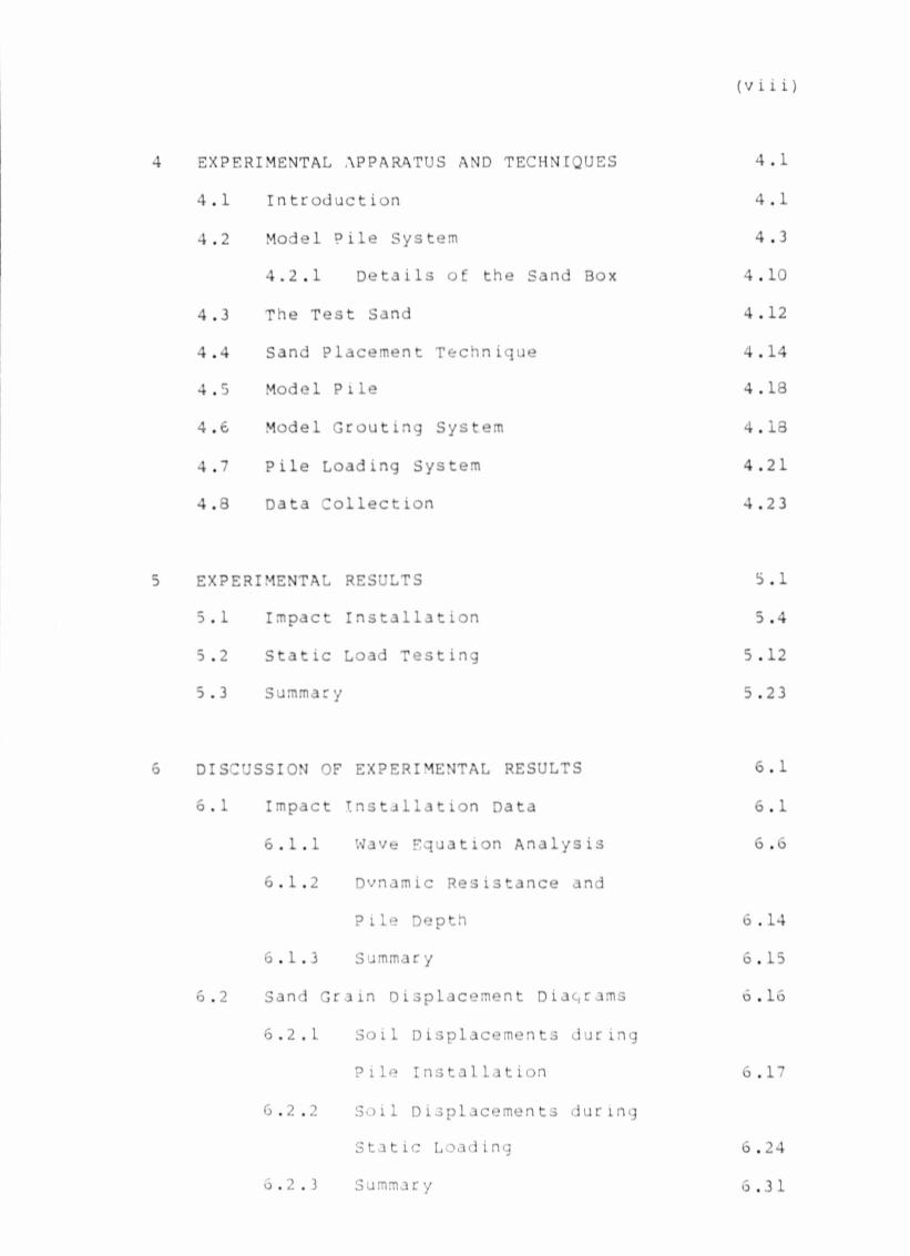
4 EXPERIMENTAL APPARATUS AND TECHNIQUES 4.1
4.1 Introduction 4.1
4.2 Model Pile System 4.3
4.2.1 Details of the Sand Box 4.10
4.3 The Test Sand 4.12
4.4 Sand Placement Technique 4.14
4.5 Model Pile 4.18
4.6 Model Grouting System 4.13
4.7 Pile Loading System 4.21
4.8 Data Collection 4.23
5 EXPERIMENTAL RESULTS 5.1
5.1 Impact Installation 5.4
5.2 Static Load Testing 5.12
5.3 Summar y 5.23
6 DISCUSSION OF EXPERIMENTAL RESULTS 6.1
o.l Impact Installation Data 6.1
6.1.1 Wave Equation Analysis 6.6
6.1.2 Dvnamic Resistance and
Plle Depth 6 .14
6.1.3 Summar y 6.15
6.2 Sand Grain Displacement Diagrams 6.16
6.2.1 Soil Displacements during
Pile Installation 6.17
6.2.2 Soil Displacements during
Static Loading 6.24
6.2.3 Summar y 6.31
(ix)
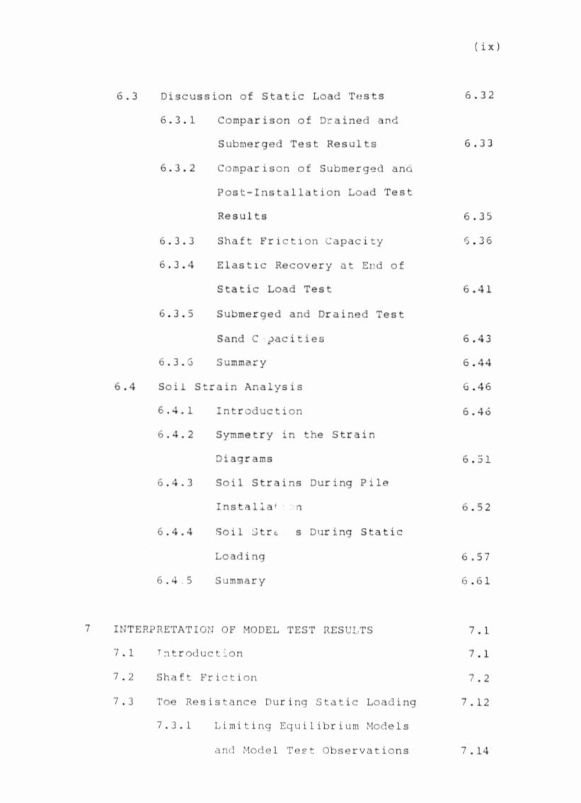
6.3 Discussion of Static Load Tests
6.3.1 Comparison of Drained and
Submerged Test Results
6.3.2 Comparison of Submerged ana
Post-Installation Load Test
Results
6.3.3 Shaft Friction Capacity
6.3.4 Elastic Recovery at End of
Static Load Test
6.3.5 Submerged and Drained Test
Sand C pacities
6.3.5 Summary
6.4 Soil Strain Analysis
6.4.1 Introduction
6.4.2 Symmetry in the Strain
Diagrams
6.4.3 Soil Strains During Pile
Instalia' n
6.4.4 Soil Strc s During Static
Load i ng
6.4.5 Summary
7 INTERPRETATION OF MODEL TEST RESULTS
7.1 t ntroduction
7.2 Shaft Friction
7.3 Toe Resistance During Static Loading
7.3.1 Limiting Equilibrium Models
and Model Test Observations
6 .32
6.33
6.35
6.36
6.41
6 .43
6.44
6.46
6.46
6.51
6.52
6.57
6.61
7 .1
7.1
7.2
7 . 12
7 . 14

(x)
7.3.2 Bearing Capacity Factory, Nq,
for the Model Pile 7.19
7.4 Comparison with Field Tests 7.22
7.5 Summary 7.25
8 SUMMARY AND RECOMMENDATIONS FOR FURTHER
WORK 8 . 1
3.1 Summary 8.1
8.2 Recommer.dations for Further Work 8.4
9 REFERENCES
10 APPENDICES
APPENDIX A A .1
A.l Measurement of Grain Displacements A.l
A . 2 Co-ordinate Transformation A.6
A . 3 Data Accuracy A . 11
A.4 Accuracy of Displacement Contour
Diagrams A . 25
A . 5 Axial Symmetry in the Model System A . 29
APPENDIX B B.l
B.l Dijv>ns ional Analysis B.l
B.1.1 Dynamic Analysis B.l
B.1.2 Static Analysis B.2
APPENDIX C
Typical Computer Printout of Wave
Equation Analysis C.l

appe*:1 x n n.l
Calculation cl Soil Strains D.l
APPENDIX E E.l
F.l Significance of the Load Data E.l
E.2 Friction Between Pile Shoe and
Glass E.2
E .3 Friction Between Plastic Separator
and Glass E.8
E.4 Friction Between Pile Shaft and
Glass Panel E. 11
(xi)
( X ’ i)
TABLE 5.1
TABLE 5.2
TABLE 5.3
TABLE 6.1
TABLE 6.2
TABLE 6.3
TABLE 6.4
TABLE 6.5
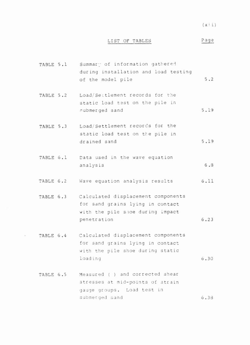
LIST OF TABLES
Summary of information gather during installation and load testing of the model pile
Load/Settlement records for the static load test on the pile in submerged sand
Load/Settlement records for the static load test on tte pile in drained sand
Data used in the wave equation analys is
Wave equation analysis results
Calculated displacement components for sand grains lying in contact with the pile s ioe during impact penetration
Calculated displacement components for sand grains lying in contact with the pile shoe during static load ing
Measured ( ) and corrected shear stresses at mid-points of strain gauge groups. Load test in submerged sand
Page
5 .2
5 . 19
5 .19
6 .3
6 . 1 1
6.23
6 .30
6.33

(xi i i)
TABLE 7.1
TABLE 7.2
TABLE 7.3
TABLE 7.4
TABLE A . 3
Measured ( ) and corrected shear stresses at mid-points of strain gauge groups. Load test in drained sand
Friction stress soil parameters determined by equation (7-1) Load test in submerged sand (for L4 load increment)
Friction stress soil parameters determined by equation (7-1).Load test in drained sand (for L8 load increment)
Friction stress soil parameters from equation (7-1) related to grout pressure. Load test in submerged sand (for L4 load increment)
Summary of some MV pile test load data. Compression tests
.1 A summary of measurement dataaccuracy for both control points and sand grains
6.38
7.6
7.6
7.7
7.23
A. 22
(:; i v )
FIGURE
FIGURE
FIGURE
FIGURE
FIGURE
FIGURE
FIGURE
FIGURE
FIGURE
FIGURE
FIGURE
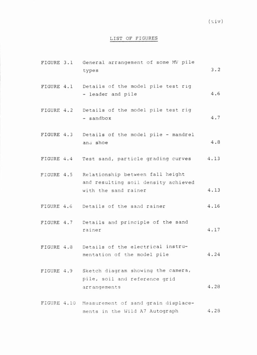
LIST OF FIGURES
.1 General arrangement of some MV pile types
.1 Details of the model pile test n g- leader and pile
.2 Details of the model pile test rig- sandbox
.3 Details of the model pile - mandrel ana shoe
.4 Test sand, particle grading curves
.5 Relationship between fall heightand resulting soil density achieved with the sand rainer
.6 Details of the sand rainer
.7 Details and principle of the sand ra iner
.8 Details of the electrical instrumentation of the model pile
.9 Sketch diagram showing the camera, pile, soil and reference grid arrangements
.10 Measurement of sand grain displacements in the Wild A7 Autograph
3.2
4.6
4.7
4.8
4. 13
4.13
4. 16
4.17
4.24
4.28
4.28
(XV)
FIGURE
FIGURE
FIGURE
FIGURE
FIGURE
FIGURE
FIGURE
FIGURE
FIGURE 5
FIGURE
FIGURE 5
'.1 Dynamic aata recorded during pileinstallation. (Refer to Plate 5.1b)
.2 Horizontal (X axis) sand graindisplacements. Plates 1-2 Dynamic.
.3 Vertical (Y axis) sand grain displacements. Plates 1-2 Dynamic.
.4 Horizontal (X axis) sand graindisplacements. Plates 1-3 Dynamic.
.5 Vertical (Y axis) sand grain displacements. Plates 1-3 Dynamic.
.6 Load/settlement behaviour of the model pxie.
.7 Settlement/time data for the model pile tests showing when soil displacements were photographed.
.8 Load distribution down the pile shaft during load testing of the pile in submerged sand.
.9 Load distribution down the pile shaft during load testing of the pile in drained sand.
.10 Horizontal (X axis) sand graindisplacements. Plates 1-2 Static.
.11 Vertical (Y axis) sand grain dis-placements. Plates 1-2 Static.
5.5
Rear pocke t
5.15
5 .16
5 .17
5 .18
Rearpocket
(xvi)
FIGURE
FIGURE
FIGURE
FIGURE
FIGURE
FIGURE
FIGURE
FIGURE 6
FIGURE 6
FIGURE 6
FIGURE 6
.12 Horizontal (X axis) sand graindisplacements. Plates 1-3 Static.
.13 Vertical (Y axis) sand graindisplacements. Plates 1-3 Static.
.14 Horizontal (X axis) sand graindisplacements. Plates 1-4 Static.
.15 Vertical (Y axis) sand graindisplacements. Plates 1-4 Static.
.16 Horizontal VX axis) sand graindisplacements. Plates 1-5 Static.
,'.7 Vertica' (Y axis) sand graindisplacements. Plates 1-5 Static.
.1 Mass/spring approximation of the model pile for the wave equation analys is
.2 Wave equation soil model
.3 Dynamic pile resistance plotted against pile penetration depth
.4 Sketch showing displacement of a sand grain remaining in contact with the pile shoe, and calculation of its displacement components
.5 Shear stress distribution down the pile shaft during the load test in submerged sand
Rea i pocket
it
ii
••
M
it
6 .7
o .10
6.15
6.23
6 .39

(xv i i)
FIGURE
FIGURE
FIGURE
FIGURE
FIGURf.
FIGURE
FIGURE
FIGURE
FIGURE
FIGURE
FIGURE
FIGURE
.6 Shear stress distribution down the oile shaft during the load test in drained sand
.7 Rectangular grid used to estimate pile installation soil strains
.8 Major principal strain contours at lO^U-strain. Plates 1-2 Dynamic.
.9 Major principal strain directions. Plates 1-2 Dynamic.
.10 Minor principal strain contours at 10 u-strain. Plates 1-2 Dynamic.
.11 Circumferential strain contours at 10^u-strain. plates 1-2 Dynamic.
.12 Maximum shear strain contours at 10^u-strain. Plates 1-2 Dynamic.
.13 Volumetric strain contours at10^u-strain. Plates 1-2 Dynamic.
.14 Major principal strain contours at lO^u-strain. Plates 1-3 Dynamic.
.15 Major principal strain directions. Plates 1-3 Dynamic.
.16 Minor principal strain contours at 10 u-strain. Plates 1-3 ?/namic.
.17 Circumferential strain contours at10 u-strain. Plates 1-3 Dynamic.
6 .40
Rear pocke t

(xv i i i)
FIGURE
FIGURE
FIGURE
FIGURE
FIGURE
FIGURE
FIGURE
FIGURE
FIGURE
FIGUKc
FIGURE
FIGURE
.18 Maximum shear strain contours at IQ"* u-strain . Plates 1-3 Dynamic.
.19 Volumetric strain contours at 10^ u- strain. Plates 1-3 Dynamic.
.20 Rectangular grid used to estimate soil strains during pile loading,
.21 Major principal strain contours at lO^u-strain. Plates 1-2 Static.
.22 Major principal strain directions. Plates 1-2 Static.
.23 Minor principal strain contours at 103 u-strain. Plates 1-2 Static.
.24 Circumferential strain contours at 10 u-strain. Plates 1-2 Static.
.25 Maximum shear strain contours at I03u-strain. Plates 1-2 Static.
.26 Volumetric strain contours at 10^U- strain. Plates 1-2 Static.
.27 Major principal strain contours at lO^u-strain. Plates 1-3 Static.
.28 Major principal strain directions. Plates 1-3 Static.
.29 Minor principal strain contours at1.0^u-strain. Plates 1-3 Static.
Re at pocket
ii
•i
ii
ii
ii
ii
M
II
II
II

(xix)
FIGURE 6.30 Circumferential strain contours at 103 u-strain. Plates 1-3 Static.
FIGURE 6.31 Maximum shear strain contours at 103 u-strain. Plates 1-3 Static.
FIGURE 6.32 Volumetric strain contours at 10 3 u- strain. Plates 1-3 Static.
FIGURE 6.33 Major principal strain contours at 10ii-atrain. Plates 1-4 static.
FIGURE 6.34 Major principal strain directions. Plates 1-4 Static.
FIGURE 6.35 Minor principal strain contours at 103 u-strain. Plates 1-4 Static.
FIGURE 6.36 Circumferential strain tort ’t3 at10 u-strain. Plates 1-4 Static.
FIGURE 6.37 Maximum shear strain contours at 103 u-strain. Plates 1-4 Static.
FIGURE 6.38 Volumetric strain contours ~ t 103u- strain. Plates 1-4 Static.
FIGURE 6.39 Major principal strain contours at 103 u-strain. Plates 1-5 Static.
FIGURE 6.40 Major principal strain directions. Plate3 1-5 Static.
FIGURE 6.41 Minor principal strain contours at 10^u-atrain. Plates 1-5 Static.
FIGURE 6.42 Circumferential strain contours at103u-strain. Plates 1-5 Static.
Rearpocket
ii
II
II
II
• I
it
II
• I
II
II
II
(XX)
FIGURE
FIGURE
FIGURE
FIGURE
FIGURE
FIGURE
FIGURE
FIGURE
i’IGURE
6.43 Maximum shear strain contours at lO^u-strain Plates 1-5 Static.
6.44 Volumetric st: 'in contours at 10 u- strain. Plates 1-5 Static.
7.1 a possible slip-line field around the model pile.
7.2 Test sand shear strength data from triaxial tests.
A.l Sketch illustrating the mechanical arrangement of Wild A7 Autograph.
A.2 Sketch illustrating how the control points on the reference grid were co-ordinated in the Wild A7 Autograph
A.3 Geometrical relationships betweencontrol points located on correctly aligned and mis-aligned photographs
\.4 Illustrates the positions of control points on a mis-aligned photograph superimposed on a correctly alignedphotogr aph
\.5 Parabolic deflection of the glass pic. te
Rearpocket
ii
7 .16
7 .17
A .4
A .4
A. 7
A.7
A . 18
FIGURE A.6 Deflection of the glass plateapproximated as a rotated plane A . 13

(xxi )
FIGURE A.
FIGURE A.
FIGURE D.
FIGURE D.
FIGURE E..
FIGURE E.;
FIGURE A. 7 Section through film holder showing possi e distortion of a sheet of photographic film
Effect of image plane rotations
Graph showing the logarithm of the displacements plotted against distance from the pile shoe
Notation for deformation of a rectangular d e m e n t .
Use of contour diagrams to obtain displacements at nodes.
Summary of force end stress Components resisting penetration of the model pile
Summary of friction lo*d components in the grout column and on the pile sha £ t
A. 18
A. 20
A.30
D . 4
D.5
E. 3
E . 9
(xxi i )
PLA'iii 4.
PLATE 4.2
PLATE 4.3
PLATE 5.1
PLATE 5.2
PLATE 5.3
LIST OF PHOTOGRAPHS
General views . pile testing equipment and plate f;im camera.
Pile loading system.
Wild A 7 Autograph.
Showinq four osci1loscopu traces of impact records on the model pile during pile installation
Showing four oscilloscope traces of impact records on the model pile obtained at various depths while installing the pile during experiment No. 8.
Showing variour aspects of the model pile after removal from the sandbox.
4.5
*.22
4.27
5.7 &3.6
5.9 & 5 .10
5.21
Page 1.1
1. INTRODUCTION
1.1 Histor ical
Piles perform their load carrying function by
transmitting the load applied at the pile head to the
underlying soils through skin friction on the pile shaft
and end bearing on the pile toe. Some piles generate
most of their load carrying capacity tnrougn shaft
friction - for example MV piles - and are therefore
suitable as "floating" or "friction" piles whereas
others, such as cased oscillator piles (eg Penoto
piles), are more suited for use as end bearing piles.
Generally, aach piling system is sufficiently different
in both installation technique and load performance for
different pile types of similar dimensions in the same
soil to develop significantly wide ranging load
capacities. Braadtvedt (1980) highlighted this point
when he stated that, depending solely on .nstallation
technique, the capacity of a pile of given dimensions
may vary by as much as a factor of six.
Piled foundations have been a recognised construction
technique for many centuries. "Certainly, as far back
as the time of Vitruvius we find piles being recommended
when a suitable foundation cannot be found by excavating?
the various lake dwellings in Europe provide examples of

still earlier use. In Arrian's Life of Alexander the
Great (Book II) a description is given of the use of
piles for the construction of the mole used for the
reduction of the city of Tyre (20th Aug., 332 3 C) "
(Little, [1961, p . 128]). Caesar, in De Bello Gallico IV
(translated by Handford [1951]} presents a detailed
description of the use of piled wooden piers for a
’-'t idge constructed across the Rhine river.
Piles were not uncommon in the foundations of medieval
structures. Little (1961, p.125), for example, mentions
the use of piles in the construction of Winchester
Cathedral (completed A D 1093) and Filarete (translated
by Spencer [1965]) describes how piles would be used for
construction of a oridge (Spencer, 1965 p.164 and 290).
The cover panels of Chellis' book "Pile Foundations"
(1961) present some excellent illustrations of medieval
and primitive pile driving equipment.
"Until somt time in the nineteenth century, wood piles
were the only common type; since then, steel, concrete
and composite piles of many kind have come into wide
use" (Taylor, 1948, p.640). It is not altogether clear
from the early literature what the exact sequence was in
either tne emergence of new pile tvpes or the development
of new installation and driving techniques. Poulos and
Davis (1980 p.l) suggest that, "Modern literature on
piles can be said to date from the publication of 'Piles
Page 1.2
and Pile Driving' edited by Wellington of the Eng j. leer ing
News ..... in 1893 .....". It is apparent, however,
that the period 1850 to 1950 saw a proliferation of pile
equipment and design techniques of large magnitude which
reflected the rapid industrial expansion of the period.
The industrialization of South Africa lagged somewhat
behind that of the northern hemisphere countries and it
was not until about 1938 that South A f r i c a ’s first
specialist piling contractor, McLaren and Eger, came
into existence.
1.2 Pile Design
Increasing cost and frequency of use of pile foundations
during the last century have obliged the foundation
engineer to develop methods to predict more accurately
and reliably the performance of the piles specified in
his design. " ..... until the late nineteenth century,
the design of pile foundations was based entirely o:
experience, or even divine providence." (Poulos and
Davis, op cit). Despite the considerable volume of
published literature on the subject, both practical and
theoretical research into pile performance parameters
have advanced hesitantly with the result that today pile
design still tends to be largely d e ^ n d e n t on empirical
data and thus on the experience of the designer.
Nevertheless, the design of a single pile foundation for
ultimate axial capacity is conveniently divisible into
Page 1.3

three major approaches which may be applied singly or in
combination. These include use o£ static bearing
capacity formulae, dynamic bearing capacity formulae and
empirical approaches ba ;ed on past experience and/or on
in situ test methods. Chapter 2 presents a brief review
of these topics.
This report presents the results of an attemp*. to obtain
data on both tne installation characteristics and ioading
benaviour of a laboratory scale model pile instai led m
Sind. The pile type used for this investigation was a
driven d l spl ace:nen t grouted in situ pile known as the MV
pile. Features of the MV pile are described in Chapter 3.
Page 1.4
Page 2 .1
2. PILE DESIGN
2.1 Static Bearing Capacity Design
Static bearing capacity design methods attempt to
determine ultimate pile capacity by use of in situ soil
strength parameters. Typically, ultimate capacity, Qu,
is expressed as the sum of the ultimate shaft friction,
Os, and the ultimate toe resistance, Qb, (eg Bowies
1977 p.523),
Qu - Qs ♦ Qb (2-1)
wher e :
Qs * As (K. pv.tan ?) (2-2)
and:
Qb * Ab (>.b.Ny.S'r ♦ c.Nc.Sc. ♦ pv.Nq.Sq) (2-3)
for which As * surface area of the pile shaft: K « a
lateral earth pressure coefficient: pv » average
effective overburden pressure along the shaft: ? ■
friction angle between pile and soil; Ab *■ area of the
pile toe: y » effective unit weight of the soil at the
pile poir- • b * toe diameter; c ■ cohesion of the
soil; pv = effective overburden pressure at the pile
toe; and N y , N c , Nq « theoretical bearing capacity
factors related to the friction angle of the soil and on
assumed failure pattern; and Sv, Sc, and Sq are shape
factor s .

No single equation has been found to be adequate for ail
s i tuat ions.
Most of the standard foundation texts describe the use
of these equations in pile design. It is not certain
where or when the static bearing capacity design
approach originated, but it is apparent (Terzahi [1943],
p.137) that it had been proposed prior to 1910.
2.2 Dynamic Bearing Capacity Design
Estimation of driven pile capacity by consideration of
the dynamics 3f the lile/hammer system, has lead to two
different approaches. The first, and historically the
oldest invol/es a large family of "dynamic formulae” .
These are based on impulse-mome.ntum principles using
classical mechanics for which an energy balance equation
is established. The equation is usually expressed in a
form in which the pile "set" (penetration per hammer
blov.) required to ensure a particular pile capacity, can
be calculated. Bowles (1977, p.561) presents an in
depth review of how the detailed version of such an
equation termed the "rational pile formula", is derived.
The second approach to the determination of driven pile
capacity by dynamic methods, is based on a mathematical
^odel using the one dimensional wave equation for stress
transmission in elastic rods.
Page 2.2
Simplifications and assumptions applied to the "rational
pile formula" by various authors have led to the
publication of a large family of related dynamic
formulae, some of which d - U from the early 1300's.
Chellis (1961 Appendix 1) lists about forty different
versions, some of which ace also discussed by Bowles
(1977) and Taylor (1948). According to Smith (1960),
"... the editors of Engineering News Record have on file
lour hundred and fifty such formulae." Terzaghi (1943
p.141-142), basing his comments on a report by Cummings
(1940), expressed reservations about both the theoretical
basis of th_- impact equations and their applicability to
the pile/soil system. He comments as follows, "On
account of tneir inherent defects all the existing pile
formulas are utterly misleading as to the influence of
vital conditions, such as the ratio between the weight
of the pile and the hammer, on the result of the pile
driving operations." Despite the undeniable objections
to the theoretical basis of the dynamic formulae, they
have remained in popular use and have been incorporated
into various standards (eg SABS 088 [1972]).
A number of statistical studies into the reliability of
dynamic pile driving formulae have been undertaken.
Some of these include the Michigan State highway
Commission (1965), Olsen and Flaate (1967) and ASCE
(1946). Although a large amount of data was considered
in these analyses, no single preferred dynamic formula
Page 2.3

could be I rivint i f >ed. The better performers were found
to inclL--,<» ■ i Hiley, Janbu and Gates formulae.
Commenting cr. the ASCE (1941) report on their
investigation into pile driving formulae, Peck (1942)
was prompted to observe that a bearing capacity formula
of Qu = 91 tons was, for the recorded data, statistically
as accurate as the dynamic formulae used to predict
their capacity.
It appears chat the first to recognise the applicability
of the "wave equation" to the analysis of pile driving
was Isaacs in 1931. Fox (in Glanville et al, 1938) also
published a driven pile solution to the wave equation.
The design method given by these two authors, however,
was not widely adopted, mainly because of the tedious
calculation involved. Edward A. Smith of the Raymond
Concrete Pile Company provided the first tractable
application of the wave equation to driven piles.
Smith formalized his ideas in publications dated 1955 and
1960. A considerable amount of practical and theoretical
research into the wave equation and related methods have
since been carried out, particularly in America. The
first international conference on the application of
stress wave theory on pile3 was held at Stockholm in
June 1980 (Bredenberg [1980]). A state of the art review
of the wave equation and a list of the major research
publications was presented oy Goble et al (1980) .
Page 2.4

So.e " :cel]ent correlations between pile capacity
pre. d by the wave equation and measured failure
loads, have been reported (eg Goble et al [1975],
Rausche et al [1972], Forehand and Reese [1964]). Goble
et. al (1975) for example indicate an error range of —
10% from the predicted pile capacity. Other authors (eg
Lowery et al [1968], Ramey and Hudgins [1977]), found
that the error ranged up to as high as — 40% while
Tavenas and Audibert (1977) concluded that there was no
correlation at all between wave equation predictions and
measured pile performance. It must oe accepted therefore
that the wave equation, in common with otner pile design
techniques, has its limitations.
2.3 Empirical Pile Design
Empirical design by the installation and testing of
trial piles is relatively expensive. Consequently, only
contracts of reasonable size can justify the experimental
costs. Further, such experiments are time consuming and
require between three and five weeks to conduct.
Because empirical design by use of full scale field
tests is not generally justifiable, much effort has been
expended in developing alternative in situ test tech
niques. Most of these involve the use of penetrometers,
tho argument for their use being that the resistance to
penetration experienced by the penetrometer can be
Page 2.5

correlated to pile bearing capacity. Also in favour of
using penetrometers as a pile design tool, is that they
are frequently used in site investigation to obtain both
soil properties and an indication of the subsurface
prof ile.
Sanglerat (1972, 1979) has described in some depth, the
theory and practice related to many of the large variety
of both static and dynamic penetrometers in use around
the world. He aiso describes an equally large variety
of pile/penetrometer design correlations. As a method
of design, it would appear that the subject is little
better off than alternative methods. Amongst the many
penetrometer pile design techniques those of Van der
Veen and Boersma (1957), de Beer (1965) and Meyerhof
(1956, 1976) may be considered the most popular.
There is considerable potential in the use of penetro
meter data for the -sign of piles. Until penetrometer/
soil interaction is properly understood, and until some
technique is developed to extrapolate this information
in a rational manner to pile behaviour however, the
design correlations must remain empirical and subject to
uncer tainty.
2.4 Comment on Pile Design
Of the three main approaches to pile design, pile bearing
capacity determination by the use of "static" formulae
P aye 2.6

is considered the most i iportant method. The static
design approach is usually used in conjunction with, or
in suppott of the other design methods, and will
therefore be routinely used in most situations where the
need for piles is being considered. Considerable
reliance is therefore often placed on this metnod.
Static pile design, however, remains a largely empirical
science. In a succinct analysis of existing design
methods, Tomlinson (1977) has drawn attention to some of
the weaknesses of the design formula. In his analysis
Tomlinson makes the following comments:
"... the effects of the various methods of pile
installation on the carrying capacity and deformation
characteristics (of piles) cannot be calculated by
strict application of soil or rock mechanics theory".
(Op cit, p.li.) Consequently, calculation of the load
carrying capacity of piles, "... is based partly on
theoretical concepts ..., but mainly on empirical
methods based on experience". (Op cit, p.10.) Despite
the apparently scientific nature of pile design,
therefore "The overriding influence of experience and
the limitations of theory make piling practice an art
rather than a scien;e . . .". (Op cit, p. 11.) In an
attempt to reduce this dependence on experience as a
necessary component in pile design, various theocetical
and practical (laboratory and full scale) studies have
been carried out to investigate the parameters thought
Page 2 .7
to affect pile behaviour. Summaries of the findings of
the major full scale investigations can be found in the
standard texts. Theoretical studies into the behaviour
of piles are limited by the ap licability of the soil
models used in the analyses and by the availability of
suitable experimental data with which to compare the
theoretical findings. Some of the laboratory scale
studies which have been carried out, are discussed in
Chapter 4. As Tomlinson notes (op cit, p.11), however,
"Attempts to study the behaviour of piles in the
laboratory have not produced any worthwhile design rules
because of the impossibility of reproducing installation
effects in model piles. At best, they have given an
insight into the fundamental matters of the transfer of
load from the pile to the soil ...". Whilst reproduction
of pile installation effects using model piles may be of
limited value when extrapolating the findings to full
scale piles, it is suggested that model pile tests
constitute the most reliable way of investigating the
mechanism of pile/soil interaction and through this, of
obtaining improved design methods.
Page 2.3

Page 3.1
3. THE MV PILE
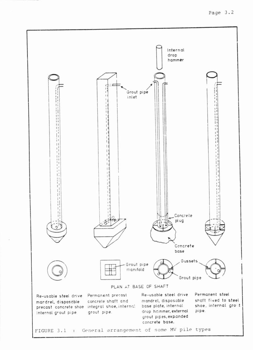
3.1 Descr i pt ion
The MV pile .nay be described is a driven displacement
grouted in situ pile. The equipment generally comprises
a p . oversize pile shoe, a drive mandrel which may or may
not be a permanent fixture and a grouted annulus which
fills the cavity formed by the shoe between the soil and
the mandrel. Pile installation is achieved by dynamic
methods and use may be made of any of the pile driving
hammer techniques including a vibro-hammer. Usually
grout is pumped continuously to the pile toe during
driving. Figure 3.1 shows the general arrangement of
some of tne MV pile types which have been used in past
contracts.
Within th:s general arrangement for the MV piling system
a considerable variety of piles can be manufactured for
particular applications. Shaft diameter and shape are
determined by the diameter and shape of the pile shoe.
Complex shapes have been used to ensure panel inter
locking for contiguous pile walling. Typically the MV
pile shoes are made of manufactured plate steel box
structures or precast reinforced concrete elements.
The drive mandrel may be made from any dimensiona1ly and
structurally suitable steel section (including hollow
Page 3 . 2
Re-usable steel dr ive m a r d r e l , d isposab le precas t concrete shoe in terna l grou t pipe
In te rn a ldrophammer
Grout pipe mani fo ld
PLAN nT BASE OF SHAFT
Gussets
Grout pipe
Permanent precast concrete s h a f t and in teg ra l shoe, i n te r n a l grou t pipe
Re-usable s tee l dr ive mandre l , d isposable base plate, i n te rna l drop hcmmer, external grou t p ipes ,expanded concrete base.
Permanent steel sha f t f i <ed to s tee l shoe , i n t e r n a l gro t p ipe
FIGURE 3.1 : General arrangement of some MV pile types
Page 3.3
sections) or it may be made from a reinforced precast
concrete column. Hollow steel section mandrels may also
be filled with concrete on completion of driving, or a
bulbous shape may be formed by driving out a concrete
plug with an internal drop hammer.
MV piles may be installed at rakes ranging from vertical
to as little as 2D degrees inclination from the
horizontal. Techniques have also been developed to
install MV piles under water. Shaft friction capacity
of MV piles in a given soil is hign in comparison to,
for example, preformed driven displacement p ;les such as
precast piles or steel joists, and is of a similar order
of magnitude to the shaft capacity of similar sized
driven displacement cast in situ pile types such as
Franki piles. For this reason MV piles are generally
identified as "friction piles'* and consequently their
most frequent application is in deep soft soils including
loose sands, and soft silty and clayey soils. Their low
driving resistance also enables MV piles to be installed
into gravels and dense sands.
Due to the hign snaft friction capacity a frequent
application of MV piles is .in tensile load applications
such as high capacity retaining wall anchors and dry
dock and weir foundations. Transmission line tower
masts and chimnev unions have also been supported
on MV piles, which, in such cases, are usea to provide
Page 3.4
reaction to both tensile and compressive loads. In
terms of numbers of piles installed the most frequent
use of MV piles has been as anchor piles, particularly
in harbour and canal construction where they have been
used as a cost effective alternative to conventional
tendon type ground anchors. The harbour authorities of
Duisborg, West Germany for example consider MV pile
anchors a preferred anchor technique, and the EAU (1975)
recommend MV piles tor retaining wail support and other
tensile load applications.
3.2 Historical development
The MV piling system was invented and developed by
Dr. -Ing Ludwig Muller in the early 1950s in West
Germany. The Company. Dr. -Ing Ludwig Muller und Sonne
Gesellschaft fur Neuzeitliche Bautechnik K.G. (later to
become Dr. -ing Ludwig Muller und Sohne Gesellscnaft fur
Bautechnik MBH i Co K.G.), was subsequently established
in Marburg an der Lahn, West Germany, to market the MV
piling system under a licensee arrangement, with
Dr. -Ing Muller remaining as patent holder and licensor.
The first licensee of the MV piling system was Dortmund
Hoeder Hiittenunion, a West German sheet pile manufac
turer, in 1955 . The initials "MV" in MV pile are an
abbreviation of the German - M uller Verpress pfahl -,
which roughly translated, means Muller grouted pile.
Page 3.5
Fundamental to the successful operation of the MV piling
system is the use of a grout with suitable stability,
flow and strengtn properties. Early MV grouts contained
materials such as trass, bentonite and asbestos fibre in
addition to a fluid sand-cement-water mix. Tricosal M V ,
an additive to MV grout which now finds wide acceptance
and success, was subsequently developed specifically for
Muller und Sohne by Chemische Fabrik Gr'unau GmbH, also
of West Germany. The original intention with early MV
piles was that the hardened grout need oe o m y as stiong
as was required to safely transfer the applied axial
load in shear to tne surrounding soil and that the drive
mandrel would be designed to support applied axial and
bending loads.
Grout made with Tricosal M V , however, possesses
sufficient strength for 1 .. to be used to both shed load
to the soil through shaft friction as well as to
function as the main axial load bearing member. The
drive mandrel thus becomes a recoverable item, and its
original function is now usually supplanted by the grout
column, reinforced as required.
To date, over 600 000m of MV piles ranging in length
from 3,0 to rarely more than 30m (typically about 3m)
and with diameter ranging from 0,1m up to 0,9m have been
installed throughout the world, but mostly in West
Germany and bordering European countries. Despite their
Page 3.6
considerable success in Europe very little appears to be
known about the MV piling system elsewhere. Begcmann
(1965) briefly refers to the MV pile in presenting a
tensile load capacity design approach using the "adhesion
jacket cone". Hammond (1967 pp. 58-61) describes MV
piles as "a driven steel pile in which pressure grouting
is ingeniously employed", and Bazant (1979 p. 363)
simply observes that MV piles are useful in resisting
tensile loads. A number of European publications
aescriue siie conditions and contractz, often with test
load data, in which MV piles were used. Some of these
include, Mtfller (1961, 1965), Kiessling (1960), Forster
(1956), Hecht (1961), Jeske and Haman (1962) and Kdhling
(1962). The "Grundbau Taschenbuch" (1966, p. 621) refers
briefly to MV piles as a general piling technique, while
MV piles are recommended as a preferred anchoring
technique in embankment construction in EAU (1975). MV
pil«'3 had not been incorporated in EAU recommendations
prior to 1975. Their inclusion in the 1975 edition
signifies impo tant recognition of the technique by
construction authorities in West Germany. The Larssen
sheet piling handbook (Larssen-Handbuch [I960])
frequently refers to MV piles, again as an alternative
to conventional ground anchors.
Jelinek (1962) submitted the first proposal for a
general design approach to MV pile bearing capacity and
Jelinek and Ostermayer (1964) discussed the tensile load
capacity of M7 piles.

Page 3.7
The Larssen-Handbuch (1960) describes the design of MV
piles when used as retaining wall anchors. Their
approach is similar to that of EAU (1975, S. 238 fl).
3.3 South African Experience
South African experience with the MV piling technique
has been limited to a single contract of significance,
though a number of small contracts nave been performed.
During 1977 GrinaKer Filed foundations (t'ty) Limited
installed some 1300m of MV piles, rated at working loads
of between 350kN and 1200kN for the Wentworth Hospital
redevelopment. The site is located in the Bluff area of
Durban, Natal, where extensive and deep deposits of
Berea Red Sand occur. Pile lengths ranged from 4m to
9m. The pilinq contract was won in competition to
vibroflotation.
An MV pile field testing programme has also been
initiated by the South African Licensees and the present
laboratory investigation is an extension of this work.

Author Guy John Evelyn
Name of thesis Behaviour Of A Model Mv Pile In Sand Bearing Capacity Implications. 1987
PUBLISHER: University of the Witwatersrand, Johannesburg
©2013
LEGAL NOTICES:
Copyright Notice: All materials on the Un i ve r s i t y o f the Wi twa te r s rand , Johannesbu rg L ib ra ry website are protected by South African copyright law and may not be distributed, transmitted, displayed, or otherwise published in any format, without the prior written permission of the copyright owner.
Disclaimer and Terms of Use: Provided that you maintain all copyright and other notices contained therein, you may download material (one machine readable copy and one print copy per page) for your personal and/or educational non-commercial use only.
The University of the Witwatersrand, Johannesburg, is not responsible for any errors or omissions and excludes any and all liability for any errors in or omissions from the information on the Library website.