
Bedienungsanleitung Operating Manual Instrução … DEUTSCH Software-Update, Kanalwechsel und...
24
Bedienungsanleitung Operating Manual Instrução de funcionamento ”EK-Tool” Supervisor 102806 D/GB/PTB12.2013
-
Upload
phungkhanh -
Category
Documents
-
view
228 -
download
0
Transcript of Bedienungsanleitung Operating Manual Instrução … DEUTSCH Software-Update, Kanalwechsel und...

BedienungsanleitungOperating Manual
Instrução de funcionamento”EK-Tool”
Supervisor
1028
06 D
/GB
/PTB
12.2
013
2
DEUTSCHDEUTSCH/ENGLISH/PorTUGUêS
Inhaltsverzeichnis Seite
Installationsanweisung 3
Software-Update, Kanalwechsel und Parameteränderungenam Empfänger per USB 5
Software-Update, Kanalwechsel und Parameteränderungenam Sender per USB 6
Kanalwechsel und Parameteränderung am Sender per Funk 7
Allgemeine Hinweise 8
Sonstiges 9
Table of contents Page
Installation instruction 10
Software update, port change and parameter change to receiver per USB 12
Software update, port change and parameter change to transmitter per USB 13
Port change and parameter change to transmitter per radio 14
General information 15
Miscellaneous 16
Índice Page
Preparação para a instalação 17
Atualizações do software, troca de canal e alterações de parâmetros no receptor por USB 19
Atualizações do software, troca de canal e alterações de parâmetros no Transmissor por USB 20
Troca de canal e alterações de parâmetros no transmissor por rádio 21
Instruções gerais 22
Outros 23

3
DEUTSCHDEUTSCH
Installationsanweisung
Vorbereitung Installation
ordner <EK-Tool>, <Sender>, <Empfänger> und <Treiber> in beliebiges Verzeichnis kopieren.
Installation EK-Tool Empfänger
1. Empfänger K52899-020 oder K52899-030 über USB-Kabel mit PC verbinden.
2. Wenn dazu aufgefordert, Suchpfad für Treiber angeben oder manuell Installation starten – ev. wird Installation auch selbstständig ausgeführt (Suchpfad: ordner Treiber, EK-Tool, Datei: PL2303_Prolific_DriverInstaller_v1.5.0.exe – bei manueller Installation PL2303_Prolific_DriverInstaller_v1.5.0.exe mit Doppelklick starten.
3. Ggf. die weiteren Anweisungen befolgen.
4. Beachten: USB-Kabel für Empfänger immer am USB-Anschluss betreiben, an dem die Installation durchgeführt wurde.
Installation USB-Programmierkabel Sender
1. USB-Programmierkabel mit PC verbinden.
2. Wenn dazu aufgefordert: Suchpfad für Treiber angeben oder manuell Setup starten (Suchpfad: ordner Treiber, USB-Programmierkabel Sender, CDM20602 – bei manueller Installation CDM20802_Setup.exe mit Doppelklick starten).
3. Ggf. die weiteren Anweisungen befolgen.
4. Beachten: USB-Programmierkabel für Sender immer am USB-Anschluss betreiben an dem die Installation durchgeführt wurde.
Sonstiges
Verknüpfung von EK_Tool_DEU.exe auf Desktop erstellen (Anwendung ist in ordner EK-Tool, Datei: EK_Tool_DEU.exe).

4
DEUTSCH
Verschiedene Berechtigungen für den Anwender
Damit der Anwender die für ihn vorgesehenen Änderungen ausführen darf, muss im gleichen Verzeichnis wie die Anwendung EK_Tool_DEU.exe die Schlüsselwortdatei WH_EKT.txt vorhan-den sein (wenn Anwendung auf Desktop gestartet werden soll bitte EK_Tool_DEU.exe immer mit “Verknüpfung erstellen“ kopieren).Über die Datei WH_EKT.txt werden die verschiedenen Berechtigungen gesteuert. In diese Datei können die Schlüsselwörter eingetragen werden, die die Berechtigungen vorgeben.Die erforderlichen Schlüsselwörter funktionieren nur wenn sie in der 1. Zeile ganz links des Textfiles stehen. Die Schlüsselwörter können nicht kombiniert werden.
Ohne Schlüsselwort oder ohne Datei:Sender: Berechtigung zum Ändern der Serien Nr., Maschinen-Bezeichnung, Funkkanal und Werkzeug-Nr.Empfänger: keine Berechtigung zum Ändern.
Mit Schlüsselwort PROGRAMMER:Sender: Berechtigung zum Ändern der Serien-Nr., Maschinen-Bezeichnung, Funkkanal und Werkzeug-Nr.Empfänger: Berechtigung zum Ändern der Serien-Nr., Maschinen-Bezeichnung und Funkkanal.
Mit Schlüsselwort SUPERVISOR:Sender: Berechtigung für alle Funktionen.Empfänger: Berechtigung für alle Funktionen.

5
DEUTSCH
Software-Update, Kanalwechsel und Parameteränderung am Empfänger per USB
1. Empfänger über USB-Kabel mit PC verbinden.
2. Anwendung EK_Tool_DEU.exe starten.
3. Kanal CoM _ _ _ wählen, bei Verbindung Schaltfläche “Verbinden“ wählen.
4. Ggf. “Stopp Senderüberw.“ anklicken damit Schaltfläche “Empfänger Einstellungen“ aktiviert wird.
5. Bei Funktionen per USB Schaltfläche “Empfänger Einstellungen“ anklicken.
6. Für Software-Update “Datei auswählen“ anklicken, (Suchpfad für Emfängersoftware ordner Empfänger, Datei: PFSys_EK_Empfaenger.hex), “Datei aufspielen“, warten bis Datenübertragung abgeschlossen, Meldung von Datenübertragung mit oK bestätigen und “Schließen“ wählen.
7. Für Kanalwechsel “Funkkanal“ 4 auswählen und entsprechend ändern, “Einstellungen aufspielen“, Meldung von Datenübertragung mit oK bestätigen und “Schließen“ wählen.
8. Für Parameteränderung “1, 2, 3 oder 5“ auswählen und entsprechend ändern, “Einstellungen aufspielen“, Meldung von Datenübertragung mit oK bestätigen und “Schließen“ wählen.
9. Vor dem Entfernen des USB-Kabels Verbindung “Trennen“ und “Programm beenden“ wählen.
1
2
3
4
5

6
DEUTSCH
Software-Update, Kanalwechsel und Parameteränderung am Sender per USB
1. Batterie entfernen.
2. Programmierkabel (USB-Stecker) mit PC verbinden (noch nicht mit Platine).
3. Anwendung EK_Tool_DEU.exe starten.
4. Programmierkabel mit Senderplatine verbinden.
5. Batterie einsetzen, LED auf Senderplatine leuchtet (sollte LED nicht leuchten muss die Sender-Elektronik aufgeweckt werden – hierzu EK-Gehäuse zu EK-Schaft min. ¼ Umdrehung verdrehen und wieder zurückdrehen, bis die Halteeinrichtung einrastet).
6. Kanal CoM _ _ _ wählen, bei Verbindung Schaltfläche “Verbinden“ wählen
7. Bei Funktionen per USB Schaltfläche “Sender Einstellungen“ wählen.
8. Für Software-Update “Datei auswählen“ anklicken, (Suchpfad für Sendersoftware ordner Sender, Datei: PFSys_EK_Sender_Abtast.hex), “Datei aufspielen“, warten bis Datenübertragung abgeschlossen, Meldung von Datenübertragung mit oK bestätigen und “Schließen“ wählen.
9. Für Kanalwechsel “Funkkanal“ 5 auswählen und entsprechend ändern, “Einstellungen aufspielen“, Meldung von Datenübertragung mit oK bestätigen und “Schließen“ wählen.
10. Für Parameteränderung “1, 2, 3, 4, 6, 7 oder 8“ auswählen und entsprechend än-dern, “Einstellungen aufspielen“, Meldung von Datenübertragung mit oK bestätigen und “Schließen“ wählen.
11. Schaltfläche Verbindung “Trennen“ wählen.
12. Batterie entfernen.
13. Programmierkabel an Senderplatine ausstecken.
14. Vor dem Entfernen des USB-Kabels bzw. zum Beenden des Programms “Programm
beenden“ wählen.
1
2
3
4
5
6
7
8

7
DEUTSCH
Kanalwechsel und Parameteränderung am Sender per Funk
1. Empfänger über USB-Kabel mit PC verbinden.2. Anwendung EK_Tool_DEU.exe starten.
3. Kanal CoM _ _ _ wählen, bei Verbindung Schaltfläche “Verbinden“ wählen.
4. Ggf. “Stopp Senderüberw.“ anklicken, damit Schaltfläche “Empfänger Einstellungen“ aktiviert wird.
5. Funkkanal für Änderungen ist 0, daher bei Bedarf Schaltfläche “Empfänger Einstellungen“ anklicken, für Kanalwechsel “Funkkanal“ auswählen und auf 0 ändern, “Einstellungen auf-spielen“, Meldung von Datenübertragung mit oK bestätigen und “Schließen“ wählen (für die Änderungen / Programmierarbeiten wird ein gesonderter Empfänger = EK-Tool verwendet – dieser Empfänger wird einmal auf Funkkanal 0 eingestellt und braucht dann nicht mehr geän-dert zu werden, dieser Empfänger ist nicht für den Einsatz als Maschinenempfänger gedacht).
6. Schaltfläche “Starte Überwachung“ wählen.
7. Sendeelektronik aufwecken, hierzu EK-Gehäuse zum EK-Schaft min ¼ Umdrehung verdre-hen und wieder zurückdrehen, bis die Halteeinrichtung einrastet.
8. Umprogrammieren aktivieren – mit Magnet seitlich neben dem Fenster (markierte Stelle) den Programmiermodus einschalten. Bitte beachten: nach dem “Aufwecken“ (Punkt 7) muss innerhalb von 2 Sekunden das Umprogrammieren aktiviert werden. Nach dem Aktivieren ist die LED auf der Senderplatine Ein (rot). Der Sender ist bereit zum Umprogrammieren und kann mit einem Empfänger auf Funkkanal 0 Kontakt aufnehmen. Der Programmiermodus ist für 2 Minuten aktiv. Innerhalb dieser Zeit muss der Umprogrammiervorgang abgeschlossen sein.
8
DEUTSCH
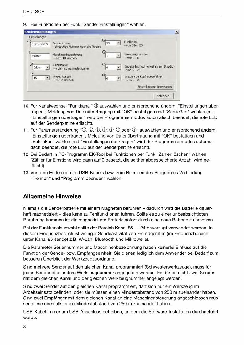
9. Bei Funktionen per Funk “Sender Einstellungen“ wählen.
10. Für Kanalwechsel “Funkkanal“ 5 auswählen und entsprechend ändern, “Einstellungen über-tragen“, Meldung von Datenübertragung mit ”oK“ bestätigen und “Schließen“ wählen (mit “Einstellungen übertragen“ wird der Programmiermodus automatisch beendet, die rote LED auf der Senderplatine erlischt).
11. Für Parameteränderung “1, 2, 3, 4, 6, 7 oder 8“ auswählen und entsprechend ändern,“Einstellungen übertragen“, Meldung von Datenübertragung mit ”oK“ bestätigen und “Schließen“ wählen (mit “Einstellungen übertragen“ wird der Programmiermodus automa-tisch beendet, die rote LED auf der Senderplatine erlischt).
12. Bei Bedarf in PC-Programm EK-Tool bei Funktionen per Funk “Zähler löschen“ wählen (Zähler für Einstiche wird dann auf 0 gesetzt, die seither abgespeicherte Anzahl wird ge-löscht)
13. Vor dem Entfernen des USB-Kabels bzw. zum Beenden des Programms Verbindung “Trennen“ und “Programm beenden“ wählen.
Allgemeine Hinweise
Niemals die Senderbatterie mit einem Magneten berühren – dadurch wird die Batterie dauer-haft magnetisiert – dies kann zu Fehlfunktionen führen. Sollte es zu einer unbeabsichtigten Berührung kommen ist die magnetisierte Batterie sofort durch eine neue Batterie zu ersetzen.
Bei der Funkkanalauswahl sollte der Bereich Kanal 85 – 124 bevorzugt verwendet werden. In diesem Frequenzbereich ist weniger Sendeaktivität von Fremdgeräten (im Frequenzbereich unter Kanal 85 sendet z.B. W-Lan, Bluetooth und Mikrowelle).
Die Parameter Seriennummer und Maschinenbezeichnung haben keinerlei Einfluss auf die Funktion der Sende- bzw. Empfangseinheit. Sie dienen lediglich dem Anwender bei Bedarf zum besseren Überblick der Werkzeugzuordnung.
Sind mehrere Sender auf den gleichen Kanal programmiert (Schwesterwerkzeuge), muss für jeden Sender eine andere Werkzeugnummer angegeben werden. Es dürfen nicht zwei Sender mit dem gleichen Kanal und der gleichen Werkzeugnummer angelegt werden.
Sind zwei Sender auf den gleichen Kanal programmiert, darf sich nur ein Werkzeug im Arbeitseinsatz befinden, oder sie müssen einen Mindestabstand von 250 m zueinander haben. Sind zwei Empfänger mit dem gleichen Kanal an eine Maschinensteuerung angeschlossen müs-sen diese ebenfalls einen Mindestabstand von 250 m zueinander haben.
USB-Kabel immer am USB-Anschluss betreiben, an dem die Software-Installation durchgeführt wurde.
1
2
3
4
5
6
7
8

9
DEUTSCH
Sonstiges
Der Sender geht nach 2 Sekunden Inaktivität, also keine Impulse vorhanden, sofort in den Sleepmodus (Sleepmodus => reset beim Wiederaufwecken).Ausnahme 1: Der Kopf ist “ausgefahren“ (Zustand wird ermittelt durch ablaufendes reedkontakt-Muster). Dann greift die “reset Auszeit“. Die Zeit bis zum Sleepmodus wird um die ”reset Auszeit“ verlängert.Ausnahme 2: Parametermodus. Man muss innerhalb von 2 Sekunden mit einem Magneten den Parametermodus aktivieren. Dann bleibt der Sender bis zum Speichern bzw. max 1 Minute aktiv (LED auf Senderplatine Ein).
Die Zeit in der der Sender aktiv ist, begrenzt sich auf die Einstichzeit + 2 Sekunden.Ist ein Stopp-Signal vorhanden wird die ”reset Auszeit“ abgeschaltet.Beispiel: Einstechdauer 9 Sek., reset Auszeit 15 Sek.:Aktive Zeit: 9 Sek. + 2 Sek. = 11 Sek.
Hinweis zu Reset Auszeit
Die Elektronik sendet ein Stopp-Signal nur wenn der komplette Einstechzyklus abgeschlossen ist.
Zweck 1 der “reset Auszeit“ ist, zu verhindern, dass beim Durchdrehen der Antriebseinheit von Hand ein Stoppsignal ausgegeben wird. Dieses Fehlsignal könnte fälschlicherweise einen EK auf einer Maschine stoppen.
Zweck 2 der “reset Auszeit“ ist, die Überbrückung der Zeit ohne Impulse im ausgefahrenen Bereich, wenn z.B. bei einer langsamen Drehzahl die Zeit ohne Impulse größer als 2 Sekunden ist.
Die “reset Auszeit“ ist daher so zu wählen, dass bei der gewählten Arbeitsdrehzahl das Stopp-Signal gesendet wird, aber beim Durchdrehen eines kompl. Einstechzyklus von Hand kein Stopp-Signal gesendet wird.Beim Standard EK wurden folgende Zeiten ermittelt:reset Auszeit 10 Sek. = kleinst möglichste Drehzahl mit Funktion auf Maschine 155 min-1
reset Auszeit 15 Sek. = kleinst möglichste Drehzahl mit Funktion auf Maschine 110 min-1
reset Auszeit 20 Sek. = kleinst möglichste Drehzahl mit Funktion auf Maschine 85 min-1
Bei einer “reset Auszeit“ von 15 Sekunden konnte durch Drehen von Hand kein Stopp-Signal erzeugt werden.
Die “reset Auszeit“ ist als Standard-Voreinstellung auf 15 Sekunden eingestellt.

10
ENGLISH
Installation instruction
Installation preparation
Copy folders <EK-Tool>, <Sender>, <receiver> and <Drivers> into optional directory.
EK Tool Receiver Installation
1. Connect receiver K52899-020 or K52899-030 through USB cable to PC.
When required enter search path for drivers or manually start installation – the installation may run automatically (search path: Folder for drivers, EK-Tool, file: PL2303_Prolific_DriverInstaller_v1.5.0.exe – for manual installation PL2303_Prolific_DriverInstaller_v1.5.0.exe – start with double click).
2. Where applicable, follow the additional instructions.
3. Note: Always connect USB cable for receiver to USB port on which the installation was conducted.
Installation of USB sender programming cable
1. Connect programming cable to PCB.2. If prompted to do so, enter search path for drivers or manually run Setup (Search path
Folder for drivers, sender USB programming cable, CDM20602 – for manual installation start CDM20802_Setup.exe with double click).
3. Where applicable, follow the additional instructions.4. Note: Always connect USB cable for sender to USB port on which the installation was
conducted.
Miscellaneous
Create short cut for EK_Tool_ENG.exe on Desktop (Application is located in Folder for EK-Tool, file EK_Tool_ENG.exe).

11
ENGLISH
Different authorizations for user
To ensure that the user can execute the changes the user is entitled to, the same directory as the EK_Tool_ENG.exe application must contain the code word file WH_EKT.txt (if application is to be run from the Desktop please always copy EK_Tool_ENG.exe with ”Create Shortcut“).The WH_EKT.txt file enables the various authorizations to be managed. Code words can be entered into this file which define the authorizations.The required code words only function when they are located in the 1st. line at the extreme left of the text file. Code words cannot be combined.
Without code word or without file:Sender: Authorization to change serial number, machine name, radio channel and tool number.receiver: No authorization to change.
With PROGRAMMER code word:Sender: Authorization to change serial number, machine name, radio channel and tool number.receiver: Authorization to change serial number, machine name, radio channel.
With SUPERVISOR code word:Sender: Authorization for all functions.receiver: Authorization for all functions.

12
ENGLISH
Software update, port change and parameter change to receiver per USB
1. Connect receiver using USB cable to PC.
2. run EK_Tool_ENG.exe application.
3. Select CoM port _ _ _, for connection press the “Connect“ button.
4. Where applicable, click on “Stop Sender Monitor“ so that the “receiver Setup“ button is activated.
5. For Actions on USB click on the “receiver Setup“ button.
6. To update software click on “GetFile“, (search path for receiver software, receiver folder, file: PFSys_EK_Empfaenger.hex), “Flash it“, wait until the data transmission has been completed, confirm data transmission prompt with oK and select “Close“.
7. To change the port select “Channel Number“ 4 and change accordingly, “Set it“, confirm data transmission prompt with oK and select “Close“.
8. To change parameters select “1, 2, 3 or 5“ and change accordingly, “Set it“, confirm data transmission prompt with oK and select “Close“.
9. Before disconnecting the USB cable connection, select “Disconnect“ and “Exit“.
1
2
3
4
5

13
ENGLISH
Software update, port change and parameter change to sender per USB
1. remove battery.
2. Connect programming cable (USB plug) to PC (do not yet connect to PCB).
3. run EK_Tool_ENG.exe application.
4. Connect programming cable to transmitter PCB.
5. Insert battery, LED on transmitter PCB lights up (if the LED fails to light up the transmitter circuit has to be woken up – to do so, turn EK housing relative to EK shaft through a ¼ rota-tion at least and then turn back again until the machine lock engages).
6. Select CoM port _ _ _, for connection press the “Connect“ button.
7. For Actions on USB functions click on the “Sender Setup“ button.
8. To update software click on “GetFile“, (search path for sender software, sender folder, file: PFSys_EK_Sender_Abtast.hex), “Flash it“, wait until the data transmission has been completed, confirm data transmission prompt with oK and select “Close“.
9. To change the port select “Channel Number“ 5 and change accordingly, “Set it“, confirm data transmission prompt with oK and select “Close“.
10. To change parameters select “1, 2, 3, 4, 6, 7 or 8“ and change accordingly, “Set it“, confirm data transmission prompt with oK and select “Close“.
11. Select “Disconnect“ connection button.
12. remove battery.
13. Plug programming cable onto sender PCB.
14. Before disconnecting the USB cable or when ending the program, select ”Exit“.
1
2
3
4
5
6
7
8

14
ENGLISH
Port change and parameter change to sender per radio
1. Connect receiver using USB cable to PC.
2. run EK_Tool_ENG.exe application.
3. Select CoM port _ _ _, for connection press the “Connect“ button.
4. Where applicable, click on “Stop Sender Monitor“ so that the “receiver Setup“ button is activated.
5. The radio channel for changes is 0, therefore if necessary click on the “receiver Setup“ button, to change a channel select “Channel Number“ and change to 0, “Set it“, confirm data transmission prompt with oK and select “Close“ (for changes / programming tasks a special receiver = EK-Tool is used – this receiver is set once to radio channel 0 and then no longer needs to be altered; this receiver is not designed for service as a machine receiver).
6. Select “run Sender“ button.
7. Wake up transmission circuit, to do so turn EK housing relative to EK shaft through a ¼ turn at least and then turn back until the machine lock engages.
8. Activate reprogramming – use magnet at side next to window (marked position) to switch on the Programming Mode. Please note: Following “Wake up“ (Point 7) the reprogramming function must be activated within a period of 2 seconds. once activated the LED on the transmitter PCB is on (red). The transmitter is ready for programming and it can make con-tact with the receiver on radio channel 0. The programming mode is active for 2 minutes. The reprogramming procedure must be completed within this period.

15
ENGLISH
9. For Actions on radio click on the “Sender Setup“ button.
10. To change channel, select ”Channel Number“ 5 and change accordingly, ”Set It“ confirm data transmission prompt with oK and select ”Close“ (”Set It“ means that the programming mode is automatically ended, the red LED on the transmitter PCB goes off).
11. To change parameter, select “1, 2, 3, 4, 6, 7 or 8“ and change accordingly, “Set It“ confirm data transmission prompt with oK and select “Close“ (“Set It“ means that the programming mode is automatically ended, the red LED on the sender PCB goes off).
12. If necessary, in the PC program EK-Tool, select “Clear Counter“ for Actions on radio (counter for grooving is reset to 0, any number saved up until that time is then deleted).
13. Before disconnecting the USB cable or when ending the program, select “Disconnect“ and “Exit“.
General information
Never touch the sender battery with magnets – if this occurs the battery is permanently magnetized – this can lead to malfunctions. Should there be any unintended contact the magne-tic battery should be replaced immediately by a new battery.
When choosing the radio channel the channel range 85 – 124 should be used. This frequency range contains a great deal less sender activity by external devices. (A frequency range at chan-nel 85 transmits, e.g. W-LAN, Bluetooth and microwave).
The serial number and machine name parameters do not exert any influence on the sender and receiver unit. They only serve to provide the user with a clearer overview of the tool allocation.
If several senders are programmed to the same channel (sister tools), then a different tool number must be allocated to each sender. Two senders with the same channel and identical tool number are not permitted.
If two senders are programmed to the same channel only one tool must be in operation or they must have a minimum distance to each other of 250 m. If two receivers with the same channel are connected to a machine control system, this must also have a minimum distance of 250 m to each other.
Always connect USB cable to USB port on which the software installation was conducted.
1
2
3
4
5
6
7
8

16
ENGLISH
Miscellaneous
The sender changes immediately to Sleep Mode after 2 seconds inactivity, i.e. no impulses (Sleep Mode => reset at wake up again).
Exception 1: The head is “outside“ (State is determined through developing reed contact samp-le). “reset Timeout“ is then activated. Time to Sleep Mode is extended by the ”reset Timeout“.
Exception 2: Parameter Mode. The Parameter Mode has to be activated within a period of 2 seconds using a magnet. The sender remains active up to saving or for a maximum of 1 minute (LED on transmitter PCB on).
The time for which the sender is active is limited by the grooving time + 2 seconds.If a Stop signal is present the ”reset Timeout“ is switched off.Example: Grooving time 9 seconds, reset Timeout 15 seconds:Active time: 9 seconds + 2 seconds = 11 seconds.
Information on Reset Timeout
The electronic circuit only transmits a Stop signal once the complete grooving cycle has been completed.
Purpose 1 of “reset Timeout“ is to prevent a stop signal from being issued when the drive unit is manually turned. This faulty signal could erroneously result in an EK tool stopping on a machine.
Purpose 2 of “reset Timeout“ is to bridge the time without any impulses in the extended range if, e.g. at a slow speed the time without any impulses is greater than 2 seconds.
“reset Timeout“ is therefore to be selected such that at the selected working speed the Stop signal is sent but when turning through a complete grooving cycle manually a Stop signal is not issued.
The following times have been determined for the standard EK tool:reset Timeout 10 seconds = Smallest possible speed with function on machine 155 min-1 (rpm)reset Timeout 15 seconds = Smallest possible speed with function on machine 110 min-1 (rpm)reset Timeout 20 seconds = Smallest possible speed with function on machine 85 min-1 (rpm)
For a “reset Timeout“ of 15 seconds a Stop signal could not be generated by manually turning.
“reset Timeout“ is configured as a default presetting at 15 seconds.

17
PorTUGUêS
Preparação para a instalação
Preparação para a instalação
Copiar a pasta <EK-Tool>, <Transmissor>, <receptor> e <Driver> em um diretório desejado
Instalação do Receptor da EK-Tool
1. Conectar o receptor K52899-020 ou K52899-030, através do cabo USB, ao PC.
2. Ao ser solicitado, informar um caminho de busca para o driver ou iniciar a instalação manual – em alguns casos, a instalação será realizada automaticamente (caminho de busca: Pasta Driver, EK-Tool, Arquivo: PL2303_Prolific_DriverInstaller_v1.5.0.exe – na instalação manual, iniciar o executável PL2303_Prolific_DriverInstaller_v1.5.0.exe com um clique duplo).
3. Siga as outras instruções se necessário.
4. observação: Sempre utilizar o cabo USB para o receptor em uma conexão USB onde a ins-talação do software tenha sido executada.
Instalação do cabo de programação USB do transmissor
1. Conectar o cabo de programação USB ao PC.2. Ao ser solicitado, informar o caminho de busca para o driver ou iniciar o Setup manual (ca-
minho de busca: Pasta Driver, Cabo de programação USB do transmissor, CDM20602 – na instalação manual, iniciar o executável CDM20802_Setup.exe com um clique duplo).
3. Siga as outras instruções se necessário.4. observação: Sempre utilizar o cabo USB para o transmissor em uma conexão USB onde a
instalação tenha sido executada.
Outros
Criar link da EK_Tool_PTB.exe na área de trabalho (o aplicativo se encontra na Pasta EK-Tool, Arquivo: EK_Tool_PTB.exe).

18
PorTUGUêS
Diferentes permissões para o usuário
Para que o usuário possa fazer as alterações previstas para ele, o arquivo de senhas WH_EKT.txt, deverá existir no mesmo diretório que o aplicativo EK_Tool_PTB.exe (se o aplicativo tiver que ser iniciado na área de trabalho, o EK_Tool_PTB.exe, deverá sempre ser criado com ”Criar link“). As diferentes permissões serão controladas através do arquivo WH_EKT.txt. Nesse arquivo é possível inserir as senhas e atribuir as permissões.As senhas necessárias só funcionam se estiverem na 1ª linha na extrema esquerda do arquivo de texto. As senhas não podem ser combinadas.
Sem senha ou sem arquivo:Transmissor: Permissão para alteração do nº de série, designação da máquina, canal de rádio e nº da ferramenta.receptor: Nenhuma permissão para alterações.
Com a senha PROGRAMMER:Transmissor: Permissão para alteração do nº de série, designação da máquina, canal de rádio e nº da ferramenta.receptor: Permissão para alteração do nº de série, designação da máquina e canal de rádio.
Com a senha SUPERVISOR:Transmissor: Permissão para todas as funções.receptor: Permissão para todas as funções.

19
PorTUGUêS
Atualizações do software, troca de canal e alterações de parâmetros no receptor por USB
1. Conectar o receptor ao PC através do cabo USB.
2. Iniciar o aplicativo EK_Tool_PTB.exe.
3. Selecionar o canal CoM _ _ _, no botão para a conexão, selecionar ”Conectar“.
4. Caso necessário, clicar em ”Parar monitoramento“, para que o botão ”Configurações do receptor“ seja ativado.
5. Para as Ação através de USB, clicar em ”Configurações do receptor“.
6. Para atualizações de software, clicar em ”Selecionar arquivo“, (caminho de busca para o software do receptor pasta receptor, arquivo: PFSys_EK_Empfaenger.hex), ”reproduzir arquivo“, aguardar até que a transmissão de dados seja concluída, confirmar o aviso de transmissão de dados com oK e selecionar ”Fechar“.
7. Para a troca de canal, selecionar ”Canal de rádio“ 4 e alterar respectivamente; selecionar ”reproduzir configurações“, confirmar aviso de transmissão de dados com oK e selecionar ”Fechar“.
8. Para a alteração de parâmetro, selecionar ”1, 2, 3 ou 5“ e alterar respectivamente; seleci-onar ”reproduzir configurações“, confirmar aviso de transmissão de dados com oK e seleci-onar ”Fechar“.
9. Antes da remoção do cabo USB, selecionar ”Desligar“ e ”Finalizar programa“.
1
2
3
4
5

20
PorTUGUêS
Atualizações do software, troca de canal e alterações de parâmetros no Transmissor por USB
1. remover a bateria.
2. Conectar o cabo de programação (conector USB) ao PC (ainda sem a placa).
3. Iniciar o aplicativo EK_Tool_PTB.exe.
4. Conectar cabo de programação à placa do transmissor.
5. Inserir a bateria, o LED da placa do transmissor acende (se o LED não acender, a eletrônica do transmissor deverá ser acordada – para isso, girar a carcaça da EK na direção do eixo da mesma com no mínimo ¼ de torção e girar de volta até que o suporte encaixe).
6. Selecionar o canal CoM _ _ _, no botão para a conexão, selecionar ”Conectar“.
7. Para as Ação de USB, clicar em ”Configurações do transmissor“.
8. Para atualizações de software, clicar em ”Selecionar arquivo“, (caminho de busca para o software do transmissor pasta Transmissor, arquivo: PFSys_EK_Sender_Abtast.hex), ”reproduzir arquivo“, aguardar até que a transmissão de dados seja concluída, confirmar o aviso de transmissão de dados com oK e selecionar ”Fechar“.
9. Para a troca de canal, selecionar ”Canal de rádio“ 5 e alterar respectivamente; selecionar ”reproduzir configurações“, confirmar aviso de transmissão de dados com oK e selecionar ”Fechar“.
10. Para a alteração de parâmetro, selecionar ”1, 2, 3, 4, 6, 7 ou 8“ e alterar respectiva-mente; selecionar ”reproduzir configurações“, confirmar aviso de transmissão de dados com oK e selecionar ”Fechar“.
11. Selecionar o botão ”Desligar“.
12. remover a bateria.
13. remover o cabo de programação da placa do transmissor.
14. Antes da remoção do cabo USB ou para a finalização da conexão do programa, selecionar ”Finalizar programa“.
1
2
3
4
5
6
7
8

21
PorTUGUêS
Troca de canal e alterações de parâmetros no transmissor por rádio
1. Conectar o receptor ao PC através do cabo USB.
2. Iniciar o aplicativo EK_Tool_PTB.exe.
3. Selecionar o canal CoM _ _ _, no botão para a conexão, selecionar ”Conectar“.
4. Caso necessário, clicar em ”Parar monitoramento“, para que o botão ”Configurações do receptor“ seja ativado.
5. o canal de rádio para alterações é 0, portanto, em caso de necessidade, clicar no botão ”Configurações do receptor“, para a troca de canal, selecionar ”Canal de rádio“ e alterar para 0, selecionar ”reproduzir configurações“, confirmar com oK o aviso da transmissão de dados e selecionar ”Fechar“ (para as alterações / programações, é utilizado um receptor especial = EK-Tool – esse receptor é configurado uma vez para o canal o e, portanto, não precisa mais ser alterado; o mesmo não é destinado para o uso como receptor da máquina).
6. Selecionar o botão ”Iniciar monitoramento“.
7. Para acordar, a eletrônica do transmissor: girar a carcaça da EK na direção do eixo da mesma, com no mínimo ¼ de torção e girar de volta até que o suporte encaixe.
8. Ativar a reprogramação – ativar o modo de programação, com a chave magnética lateral ao lado da janela (local marcado). observação: após o “acordar“ (item 7), é preciso que a desprogramação seja ativada dentro de 2 segundos. Após a ativação, o LED na placa do transmissor acende (vermelho). o transmissor estará pronto para a desprogramação e poderá estabelecer contato com um receptor no canal de rádio 0. o modo de programação permanece ativo por 2 minutos. Durante esse tempo, o processo de desprogramação deverá ser concluído.

22
PorTUGUêS
Para as Ação de rádio, selecionar ”Configurações“. Para a troca de canal, selecionar ”Canal de rádio“ 5 e alterar respectivamente; selecio-nar ”reproduzir configurações“, confirmar Transmissão de dados com ”oK“ e selecionar ”Fechar“ (com ”reproduzir configurações“, o modo de programação é finalizado automati-camente e o LED vermelho da placa do transmissor apaga).
9. Para a alteração de parâmetros, selecionar ”1, 2, 3, 4, 6, 7 ou 8“ e alterar respectiva-mente; selecionar ”reproduzir configurações“, confirmar aviso de transmissão de dados com ”oK“ e selecionar ”Fechar“ (com ”reproduzir configurações“, o modo de programação é finalizado automaticamente e o LED vermelho da placa do transmissor apaga).
10. Em caso de necessidade no programa do PC da EK-TooL em Ação des rádio, selecionar ”Apagar contador“ (o contador para punções será definido para 0, o número armazenado até o momento será apagado).
11. Antes da remoção do cabo USB ou para a finalização da conexão do programa, selecionar ”Desligar“ e ”Finalizar programa“.
Instruções gerais
Nunca toque na bateria do transmissor com um magneto – se fizer isso, a bateria será magne-tizada permanentemente – isso pode causar erros nas funções. Se ocorrer um contato indeseja-do, a bateria magnetizada deverá ser trocada imediatamente por uma nova bateria.
Ao selecionar um canal de rádio, as faixas entre os canais 85 – 124, devem ser as preferenci-ais. Nessas frequências de transmissão ocorrem menos atividades de transmissão de outros equipamentos. (A faixa de frequências abaixo do canal 85, são utilizadas, por exemplo, pelas W-Lan, Bluetooth e microondas).
os parâmetros Número de série e Designação da máquina, não influem de forma alguma na função da unidade de transmissão ou envio. Eles servem apenas para que o usuário, em caso de necessidade, tenha uma melhor visão geral da atribuição da ferramenta.
Se diversos transmissores estiverem programados para o mesmo canal (ferramentas iguais), será necessário atribuir um número de série diferente para cada número de ferramenta. Não é possível criar dois transmissores com o mesmo canal e o mesmo número de ferramenta.
Se dois transmissores forem programados no mesmo canal, apenas uma ferramenta poderá ser utilizada por vez ou, as mesmas deverão estar afastadas a uma distância mínima de 250 m. Se dois receptores com o mesmo canal, estiverem conectados a um controlador de máquina, esses deverão estar também afastados a uma distância mínima de 250 m.
Sempre utilizar o cabo USB em uma conexão USB, onde a instalação do software tenha sido executada.
4
1
2
3
5
6
7
84
23
PorTUGUêS
Outros
o transmissor entra imediatamente em modo de hibernação após 2 segundos de inatividade, ou seja quando nenhum impulso existir (modo de hibernação => reset no retorno da atividade).Exceção 1: o cabeçote foi ”movimentado para fora“ (o estado é determinado através do modelo corrente de contato reed). Em seguida, ”redefinir tempo limite“ assume. o tempo para o modo de hibernação é prolongado pelo comando ”redefinir tempo limite“.Exceção 2: Modo parâmetro. É preciso ativar o modo parâmetro, dentro de 2 segundos, com um magneto. Com isso, o transmissor permanece no máx. 1 minuto ativo até o armazenamento (o LED na placa do transmissor está ligado).
o tempo no qual o transmissor está ativo, se limita ao tempo de punção + 2 segundos.Se um sinal de parada estiver presente, o comando ”redefinir tempo limite“ é desligado.Exemplo Tempo de punção 9 seg., Tempo de redefinição de limite, 15 seg:Tempo ativo: 9 seg + 2 seg = 11 seg.
Observação sobre o comando Redefinir tempo limite
A eletrônica envia um sinal de parada, somente quando o ciclo completo de punção estiver concluído.A 1ª finalidade do ”redefinir tempo limite“ é evitar que quando a unidade de acionamento for girada, um sinal de parada seja dado manualmente. Esse sinal indevido poderia erroneamente parar uma EK em uma máquina.A 2ª finalidade do ”redefinir tempo limite“ é o override do tempo sem impulso em área já passa-da, quando, p.ex., em uma rotação lenta, o tempo sem impulso for maior do que 2 segundos.
Portanto, o comando ”redefinir tempo limite“ deverá ser selecionado, de forma que o sinal de parada, na rotação selecionada, seja enviado, mas na conclusão de um ciclo de punção completo, nenhum sinal manual seja enviado.
Na EK padrão, foram apurados os seguintes tempos:• redefinição de tempo limite para 10 seg. = menor rotação possível com função em máquina
155 min-1 (rpm)• redefinição de tempo limite para 15 seg. = menor rotação possível com função em máquina
110 min-1 (rpm)• redefinição de tempo limite para 20 seg. = menor rotação possível com função em máquina
85 min-1 (rpm)
Em uma ”redefinição de tempo“ de 15 segundos, não foi possível, através de rotação, criar um sinal manual de parada.
A ”redefinição de tempo limite“ é por padrão, definida para 15 segundos.

Wohlhaupter GmbH PräzisionswerkzeugeMaybachstraße 4 72636 FrickenhausenPostfach 1264 72633 FrickenhausenTel. +49 (0)7022 408-0 Fax +49 (0)7022 408-212www.wohlhaupter.com E-Mail: [email protected]
Wohlhaupter ProgrammWohlhaupter rangeLe programme Wohlhaupter
Zertifiziertes Qualitätsmanagement – bei Wohlhaupter selbstverständlichCertificated Quality Management goes
without saying with WohlhaupterLe management de la qualité est
naturellement certifié chez Wohlhaupter
Allg_Rueckseite_Layout 1 11.09.13 12:44 Seite 1