Beat the Book - Mouser Electronics
14
Application Note Work safely This application note is intended as a guide for the professional mechanic. It describes some of the test procedures commonly used by experienced technicians. However, some of the procedures require you to take certain pre- cautions to avoid personal injury and/or damage to equipment or vehicles. Fluke cannot anticipate all possible precautions that you must take on all the different vehicles for which this guide is applicable. For this reason, you should thoroughly familiarize yourself with proper safety habits and take all precautions described in the vehicle’s repair manuals to avoid injury or damage. Testing automotive systems with an analog/digital multimeter Perhaps the most important tool you’ll use in troubleshoot- ing auto electrical systems is the multimeter. The basic multimeter measures voltage, current and resistance, while more elaborate multimeters, such as the new Fluke 88V, have features that can check things such as frequency, duty cycle, pulse width, make diode tests, and even measure temperature. In this application note you will find troubleshooting tech- niques using the high quality, affordable and popular line of Fluke analog/digital multimeters and automotive troubleshooting accessories. Fluke’s analog/ digital combination has distinct advantages over either digital or analog meters alone, and the accessories are designed to make your job easier and more profitable. Beat the Book Automotive electrical diagnosis. Better diagnosis, faster repair. From the Fluke Digital Library @ www.fluke.com/library Although automotive multi- meters with various capabilities have been around for years, many of them didn’t have the scales and functions required for todays’ automotive applica- tions. Hybrid, electric and fuel cell powered vehicles have special requirements, ones met with the new 88V. Now that computers and their sensors are a part of everyday automobile troubleshooting, you need a true multimeter to do the job. The common analog type mul- timeter is not only inadequate, it can damage delicate computer circuitry. Both analog meters and test lights, due to their low internal resistance (input imped- ance), draw too much power from the device they’re testing to be used on computers. What’s more, many analog meters use 9 V to power the resistance test, which is enough to destroy sensitive digital components.
Transcript of Beat the Book - Mouser Electronics

Application Note
Work safelyThis application note is intended as a guide for the professional mechanic. It describes some of the test procedures commonly used by experienced technicians. However, some of the procedures require you to take certain pre-cautions to avoid personal injury and/or damage to equipment or vehicles. Fluke cannot anticipate all possible precautions that you must take on all the different vehicles for which this guide is applicable. For this reason, you should thoroughly familiarize yourself with proper safety habits and take all precautions described in the vehicle’s repair manuals to avoid injury or damage.
Testing automotive systems with an analog/digital multimeterPerhaps the most important tool you’ll use in troubleshoot-ing auto electrical systems is the multimeter. The basic multimeter measures voltage, current and resistance, while more elaborate multimeters, such as the new Fluke 88V, have features that can check things such as frequency, duty cycle, pulse width, make diode tests, and even measure temperature.
In this application note you will find troubleshooting tech-niques using the high quality, affordable and popular line of Fluke analog/digital multimeters and automotive troubleshooting accessories. Fluke’s analog/ digital combination has distinct advantages over either digital or analog meters alone, and the accessories are designed to make your job easier and more profitable.
Beat the BookAutomotive electrical diagnosis. Better diagnosis, faster repair.
F r o m t h e F l u k e D i g i t a l L i b r a r y @ w w w . f l u k e . c o m / l i b r a r y
Although automotive multi-meters with various capabilities have been around for years, many of them didn’t have the scales and functions required for todays’ automotive applica-tions. Hybrid, electric and fuel cell powered vehicles have special requirements, ones met with the new 88V. Now that computers and their sensors are a part of everyday automobile troubleshooting, you need a true multimeter to do the job.
The common analog type mul-timeter is not only inadequate, it can damage delicate computer circuitry. Both analog meters and test lights, due to their low internal resistance (input imped-ance), draw too much power from the device they’re testing to be used on computers. What’s more, many analog meters use 9 V to power the resistance test, which is enough to destroy sensitive digital components.
The presence of voltage tells you that the circuit is delivering elec-tricity to the component you’re testing.
The voltage reading tells you whether the proper voltage is arriving at the component.
By measuring available volt-age at a component, you can determine whether the voltage reaching the device is adequate.
The voltage drop across a component tells you how much of the voltage is being consumed by that component.
For example, if a relay has 12.8 volts on the input side and only 9.2 volts on the output side, the voltage drop is said to be 3.6 volts. Remember that wire and connections can also be considered components and may cause voltage drops if faulty.
2 Fluke Corporation Beat the book
Over the last couple decades, a different type of multimeter has evolved to solve problems not addressed by analog multimeters. Digital multimeters (DMMs) have much higher input impedance than analog meters, generally 1 Meg ohms (million ohms) to 10 Meg ohms. The high imped-ance means that the meter will draw very little power from the component under test. Besides providing more accurate mea-surements, this type of meter will not damage sensitive computers.
The one problem with digi-tal readouts has been that the numbers displayed didn’t give much information about whether the reading was increasing or decreasing. You may have expe-rienced the frustration of trying to read the constantly changing numbers on digital exhaust gas analyzers or scan tools.
Fluke has overcome the prob-lems associated with traditional analog and digital meters by providing a combination display that gives you the accuracy of a digital readout with the dynamic measurement capabilities of an analog meter. Rather than adding new meters to test every gizmo that comes along, one good multimeter will suffice.
Thinking about troubleshootingWhen troubleshooting electrical systems, it’s important to use a logical process of deductive reasoning to solve the problem. This process is most important since you can’t see inside or dismantle the majority of electri-cal components to tell whether they’re functioning, as you can with mechanical devices.
Jumping to conclusions can be expensive and time consum-ing. With well thought-out and organized steps, you can usually determine the source of the prob-lem the first time.
The key tool in this process is the DMM.
Types of measurementsWhen troubleshooting auto-electrical systems, you measure voltage, current and resistance. Probably the easiest and most useful measurement is voltage. It can answer these questions:
• Is voltage present?
• What is the voltage reading?
• What is the available voltage?
• What is the voltage drop across a component or connector?
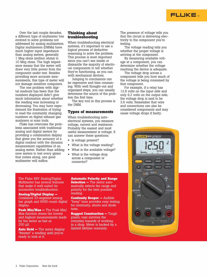
The Fluke 88V Analog/Digital Multimeter has several features that make it well suited for automotive troubleshooters:Analog/Digital Display — Combined 33-segment analog bar graph and 6000-count digital display.Peak Min/Max — The Peak Min/Max function stores the lowest and highest measurements made by the meter as fast as 250 µS.Auto Hold — The meter display “freezes” a reading until you’re ready to look at it.
Automatic Polarity and Range Selection — The meter auto-matically selects the range and polarity for the best possible reading.Continuity Beeper — Audible “beep” tone provides easy testing for continuity, shorts and diode tests.Rugged Construction — Tough plastic case survives the everyday hazards of working in a shop. Meter is backed by a limited lifetime warranty.
Vol
ts A
C
Vol
ts D
C
Mill
ivol
ts
Ohm
s
Cont
inui
ty
Dio
de T
est
Am
ps D
C*
Hz
% D
uty
Cycl
e
mS
Puls
e W
idth
RPM
**
Tem
pera
ture
Pres
sure
***
Vac
uum
***
Min
/Max
Bar
Gra
ph
3 Fluke Corporation Beat the book
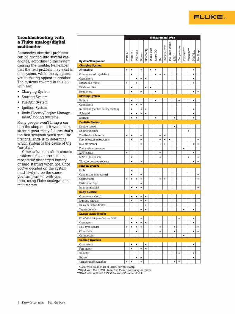
Troubleshooting with a Fluke analog/digital multimeterAutomotive electrical problems can be divided into several cat-egories, according to the system causing the trouble. Remember that the real problem may exist in one system, while the symptoms you’re testing appear in another. The systems covered in this bul-letin are:
• Charging System
• Starting System
• Fuel/Air System
• Ignition System
• Body Electric/Engine Manage-ment/Cooling Systems
Many people won’t bring a car into the shop until it won’t start, so for a great many failures that’s the first symptom you’ll see. The first challenge is to determine which system is the cause of the “no-start.”
Other failures result in chronic problems of some sort, like a repeatedly discharged battery or hard starting when hot. Once you’ve decided on the system most likely to be the cause, you can proceed with your tests, using Fluke analog/digital multimeters.
Measurement Type
System/Component
Charging System Alternators • • • • • •
Computerized regulators • • • • •
Connectors • • • •
Diodes (ac ripple) • • •
Diode rectifier • • •
Regulators • • • • • Starting System Battery • • • •
Connectors • • •
Interlocks (neutral safety switch) • • • •
Solenoid • • • • •
Starters • • • • •
Fuel/Air System Engine speed •
Engine vacuum • Feedback carburetor • • • • •
Fuel injectors (electronic) • • • • • • Idle air motors • • • • • Fuel system pressure •
MAF sensor • • • MAP & BP sensors • • • • Throttle position sensors • • • • Igniton System Coils •
Condensors (capacitors) • • • Contact sets • • • • • • • Distributor cap •
Ignition modules • • • • Body Electric Compressor clutch • • • •
Lighting circuits • • •
Relay & motor diodes •
Transmissions • • • •
Engine Management Computer temperature sensors • • • •
Connectors • • • • •
Hall-type sensor • • • • • • • O2 sensors • • • • • Oil pressure •
Cooling Systems Connectors • • • •
Fan motor • • •
Radiator • •
Relays • • •
Temperature switches • • • • •
*Used with Fluke i410 or i1010 current clamp **Used with the RPM80 Inductive Pickup accessory (included)***Used with optional PV350 Pressure/Vacuum Module
4 Fluke Corporation Beat the book
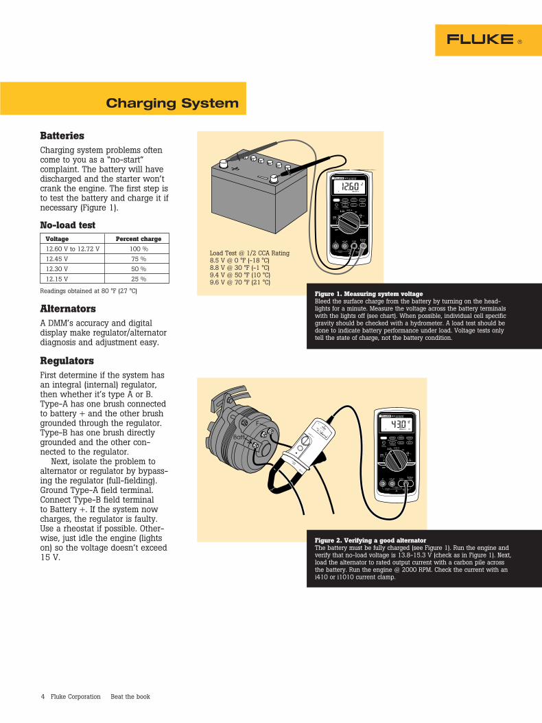
BatteriesCharging system problems often come to you as a “no-start” complaint. The battery will have discharged and the starter won’t crank the engine. The first step is to test the battery and charge it if necessary (Figure 1).
No-load test Voltage Percent charge
12.60 V to 12.72 V 100 %
12.45 V 75 %
12.30 V 50 %
12.15 V 25 %
Readings obtained at 80 °F (27 °C)
AlternatorsA DMM’s accuracy and digital display make regulator/alternator diagnosis and adjustment easy.
RegulatorsFirst determine if the system has an integral (internal) regulator, then whether it’s type A or B. Type-A has one brush connected to battery + and the other brush grounded through the regulator. Type-B has one brush directly grounded and the other con-nected to the regulator.
Next, isolate the problem to alternator or regulator by bypass-ing the regulator (full-fielding). Ground Type-A field terminal. Connect Type-B field terminal to Battery +. If the system now charges, the regulator is faulty. Use a rheostat if possible. Other-wise, just idle the engine (lights on) so the voltage doesn’t exceed 15 V.
Charging System
Load Test @ 1/2 CCA Rating8.5 V @ 0 °F (-18 °C)8.8 V @ 30 °F (-1 °C)9.4 V @ 50 °F (10 °C)9.6 V @ 70 °F (21 °C)
Figure 1. Measuring system voltageBleed the surface charge from the battery by turning on the head-lights for a minute. Measure the voltage across the battery terminals with the lights off (see chart). When possible, individual cell specific gravity should be checked with a hydrometer. A load test should be done to indicate battery performance under load. Voltage tests only tell the state of charge, not the battery condition.
ZERO
A
600V 600A
CAT
A
RR
NT LAMP 600V
TPUT mV
T
i10
Figure 2. Verifying a good alternatorThe battery must be fully charged (see Figure 1). Run the engine and verify that no-load voltage is 13.8-15.3 V (check as in Figure 1). Next, load the alternator to rated output current with a carbon pile across the battery. Run the engine @ 2000 RPM. Check the current with an i410 or i1010 current clamp.
5 Fluke Corporation Beat the book
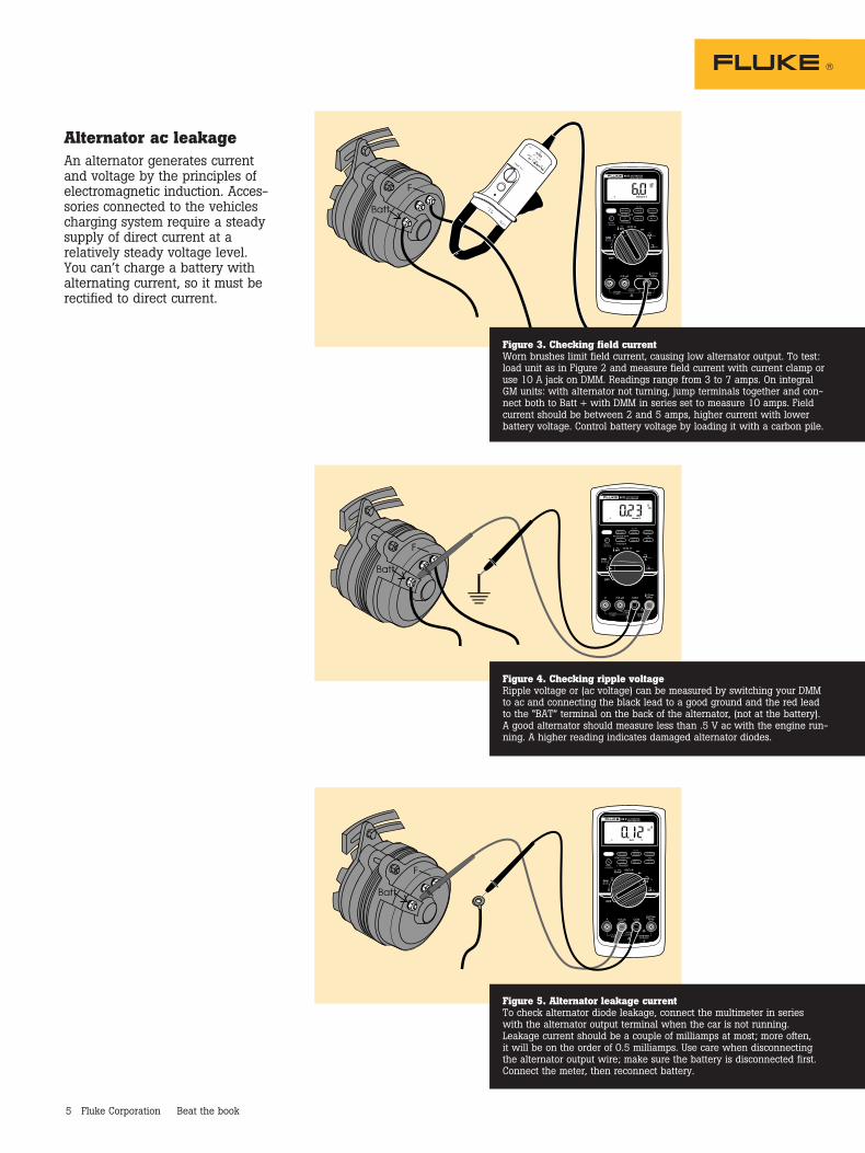
Alternator ac leakageAn alternator generates current and voltage by the principles of electromagnetic induction. Acces-sories connected to the vehicles charging system require a steady supply of direct current at a relatively steady voltage level. You can’t charge a battery with alternating current, so it must be rectified to direct current.
Figure 5. Alternator leakage currentTo check alternator diode leakage, connect the multimeter in series with the alternator output terminal when the car is not running. Leakage current should be a couple of milliamps at most; more often, it will be on the order of 0.5 milliamps. Use care when disconnecting the alternator output wire; make sure the battery is disconnected first. Connect the meter, then reconnect battery.
Figure 4. Checking ripple voltageRipple voltage or (ac voltage) can be measured by switching your DMM to ac and connecting the black lead to a good ground and the red lead to the “BAT” terminal on the back of the alternator, (not at the battery). A good alternator should measure less than .5 V ac with the engine run-ning. A higher reading indicates damaged alternator diodes.
ZERO
A
60V 0
A
CAT
AD
RR
NT LAMP 600V
UTUT mV
T
i10
Figure 3. Checking field currentWorn brushes limit field current, causing low alternator output. To test: load unit as in Figure 2 and measure field current with current clamp or use 10 A jack on DMM. Readings range from 3 to 7 amps. On integral GM units: with alternator not turning, jump terminals together and con-nect both to Batt + with DMM in series set to measure 10 amps. Field current should be between 2 and 5 amps, higher current with lower battery voltage. Control battery voltage by loading it with a carbon pile.
Z
0
600V 600
T
00600V
TT
V
T
6 Fluke Corporation Beat the book
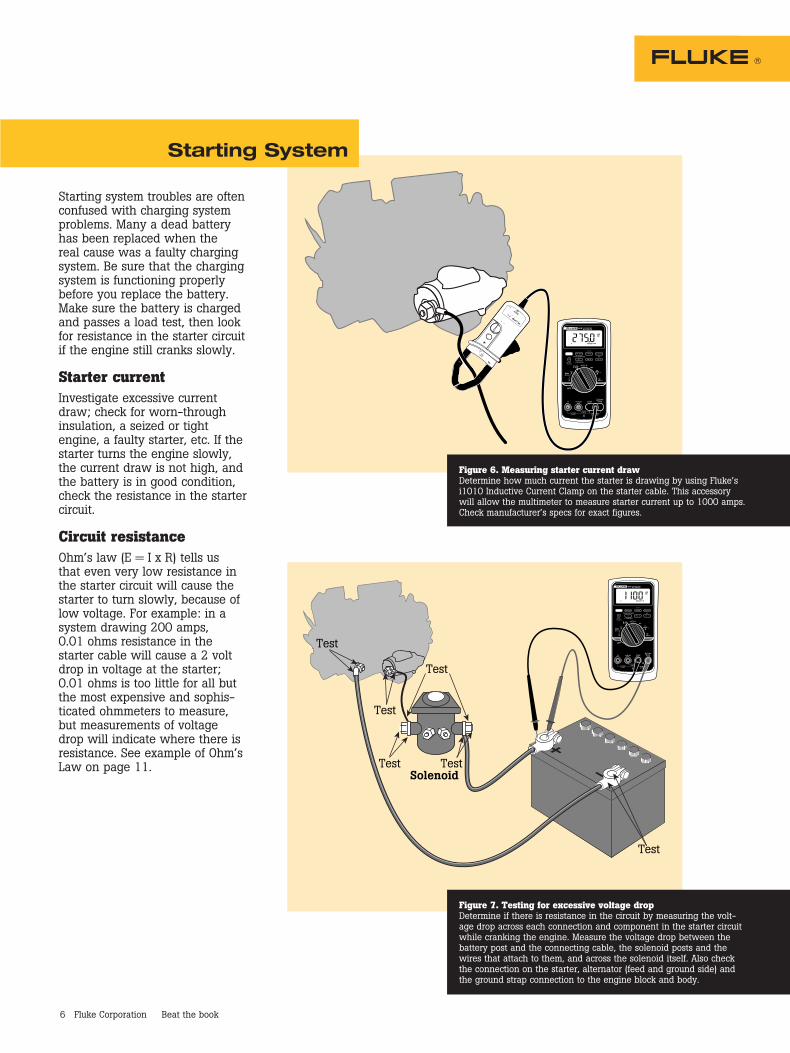
Starting system troubles are often confused with charging system problems. Many a dead battery has been replaced when the real cause was a faulty charging system. Be sure that the charging system is functioning properly before you replace the battery. Make sure the battery is charged and passes a load test, then look for resistance in the starter circuit if the engine still cranks slowly.
Starter currentInvestigate excessive current draw; check for worn-through insulation, a seized or tight engine, a faulty starter, etc. If the starter turns the engine slowly, the current draw is not high, and the battery is in good condition, check the resistance in the starter circuit.
Circuit resistanceOhm’s law (E = I x R) tells us that even very low resistance in the starter circuit will cause the starter to turn slowly, because of low voltage. For example: in a system drawing 200 amps, 0.01 ohms resistance in the starter cable will cause a 2 volt drop in voltage at the starter; 0.01 ohms is too little for all but the most expensive and sophis-ticated ohmmeters to measure, but measurements of voltage drop will indicate where there is resistance. See example of Ohm’s Law on page 11.
Starting System
Figure 6. Measuring starter current drawDetermine how much current the starter is drawing by using Fluke’s i1010 Inductive Current Clamp on the starter cable. This accessory will allow the multimeter to measure starter current up to 1000 amps. Check manufacturer’s specs for exact figures.
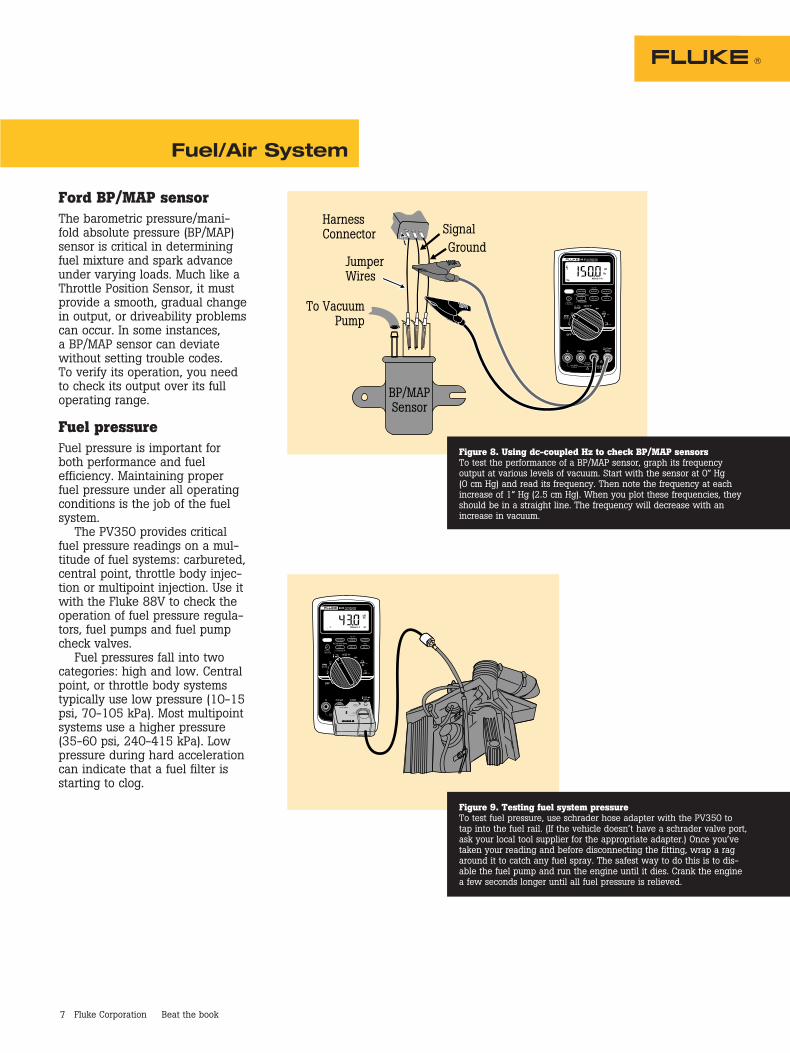
TestSolenoid
Test
Test
Test
Test
Test
Figure 7. Testing for excessive voltage dropDetermine if there is resistance in the circuit by measuring the volt-age drop across each connection and component in the starter circuit while cranking the engine. Measure the voltage drop between the battery post and the connecting cable, the solenoid posts and the wires that attach to them, and across the solenoid itself. Also check the connection on the starter, alternator (feed and ground side) and the ground strap connection to the engine block and body.
7 Fluke Corporation Beat the book
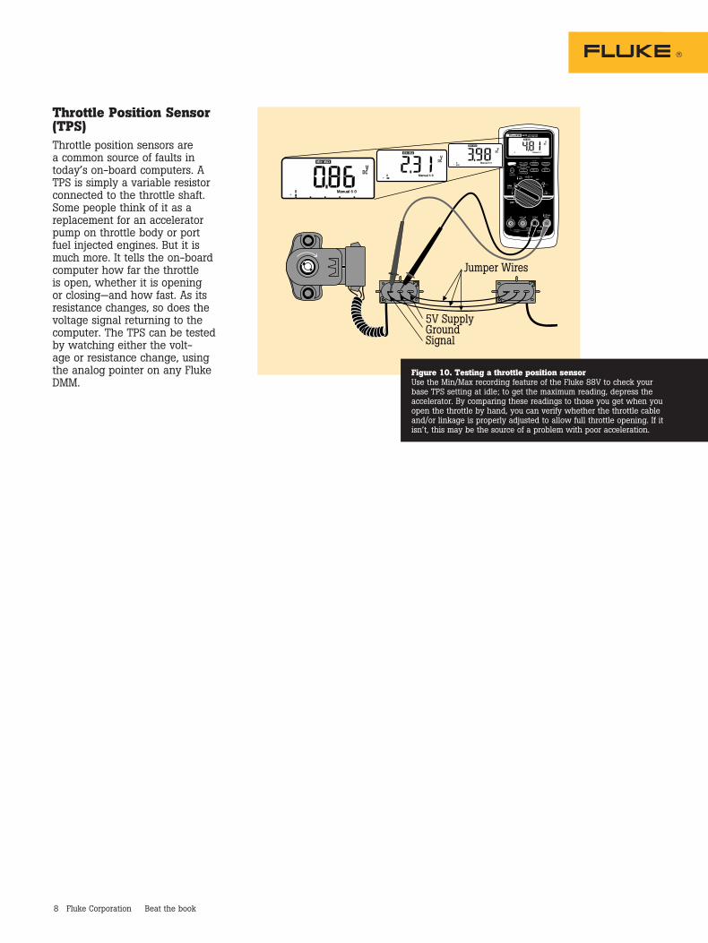
Ford BP/MAP sensorThe barometric pressure/mani-fold absolute pressure (BP/MAP) sensor is critical in determining fuel mixture and spark advance under varying loads. Much like a Throttle Position Sensor, it must provide a smooth, gradual change in output, or driveability problems can occur. In some instances, a BP/MAP sensor can deviate without setting trouble codes. To verify its operation, you need to check its output over its full operating range.
Fuel pressureFuel pressure is important for both performance and fuel efficiency. Maintaining proper fuel pressure under all operating conditions is the job of the fuel system.
The PV350 provides critical fuel pressure readings on a mul-titude of fuel systems: carbureted, central point, throttle body injec-tion or multipoint injection. Use it with the Fluke 88V to check the operation of fuel pressure regula-tors, fuel pumps and fuel pump check valves.
Fuel pressures fall into two categories: high and low. Central point, or throttle body systems typically use low pressure (10-15 psi, 70-105 kPa). Most multipoint systems use a higher pressure (35-60 psi, 240-415 kPa). Low pressure during hard acceleration can indicate that a fuel filter is starting to clog.
Fuel/Air System
HarnessConnector
JumperWires
To VacuumPump
SignalGround
BP/MAPSensor
Figure 8. Using dc-coupled Hz to check BP/MAP sensorsTo test the performance of a BP/MAP sensor, graph its frequency output at various levels of vacuum. Start with the sensor at 0” Hg (O cm Hg) and read its frequency. Then note the frequency at each increase of 1” Hg (2.5 cm Hg). When you plot these frequencies, they should be in a straight line. The frequency will decrease with an increase in vacuum.
PV350
Figure 9. Testing fuel system pressureTo test fuel pressure, use schrader hose adapter with the PV350 to tap into the fuel rail. (If the vehicle doesn’t have a schrader valve port, ask your local tool supplier for the appropriate adapter.) Once you’ve taken your reading and before disconnecting the fitting, wrap a rag around it to catch any fuel spray. The safest way to do this is to dis-able the fuel pump and run the engine until it dies. Crank the engine a few seconds longer until all fuel pressure is relieved.
8 Fluke Corporation Beat the book
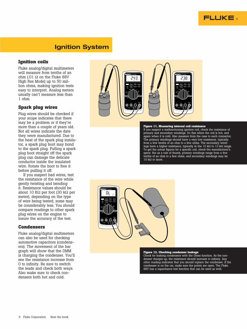
Throttle Position Sensor (TPS)Throttle position sensors are a common source of faults in today’s on-board computers. A TPS is simply a variable resistor connected to the throttle shaft. Some people think of it as a replacement for an accelerator pump on throttle body or port fuel injected engines. But it is much more. It tells the on-board computer how far the throttle is open, whether it is opening or closing—and how fast. As its resistance changes, so does the voltage signal returning to the computer. The TPS can be tested by watching either the volt-age or resistance change, using the analog pointer on any Fluke DMM.
5V SupplyGroundSignal
Jumper Wires
Figure 10. Testing a throttle position sensorUse the Min/Max recording feature of the Fluke 88V to check your base TPS setting at idle; to get the maximum reading, depress the accelerator. By comparing these readings to those you get when you open the throttle by hand, you can verify whether the throttle cable and/or linkage is properly adjusted to allow full throttle opening. If it isn’t, this may be the source of a problem with poor acceleration.
9 Fluke Corporation Beat the book
Ignition coilsFluke analog/digital multimeters will measure from tenths of an ohm (.01 Ω on the Fluke 88V High Res Mode) up to 50 mil-lion ohms, making ignition tests easy to interpret. Analog meters usually can’t measure less than 1 ohm.
Spark plug wiresPlug wires should be checked if your scope indicates that there may be a problem or if they’re more than a couple of years old. Not all wires indicate the date they were manufactured. Due to the heat of the spark plug insula-tor, a spark plug boot may bond to the spark plug. Pulling a spark plug boot straight off the spark plug can damage the delicate conductor inside the insulated wire. Rotate the boot to free it before pulling it off.
If you suspect bad wires, test the resistance of the wire while gently twisting and bending it. Resistance values should be about 10 KΩ per foot (30 kΩ per meter), depending on the type of wire being tested; some may be considerably less. You should compare readings to other spark plug wires on the engine to insure the accuracy of the test.
CondensersFluke analog/digital multimeters can also be used for checking automotive capacitors (condens-ers). The movement of the bar graph will show that the DMM is charging the condenser. You’ll see the resistance increase from 0 to infinity. Be sure to switch the leads and check both ways. Also make sure to check con-densers both hot and cold.
Ignition System
Figure 11. Measuring internal coil resistanceIf you suspect a malfunctioning ignition coil, check the resistance of primary and secondary windings. Do this when the coil is hot, and again when it is cold. Also measure from the case to each connector. The primary windings should have a very low resistance, typically from a few tenths of an ohm to a few ohms. The secondary wind-ings have a higher resistance, typically in the 10 kΩ to 13 kΩ range. To get the actual figures for a specific coil, check the manufacturer’s specs. But as a rule of thumb, primary windings range from a few tenths of an ohm to a few ohms, and secondary windings may be 10 kΩ or more.
Figure 12. Checking condenser leakageCheck for leaking condensers with the Ohms function. As the con-denser charges up, the resistance should increase to infinity. Any other reading indicates that you should replace the condenser. If the condenser is on the car, make sure the points are open. The Fluke 88V has a capacitance test function that can be used as well.

10 Fluke Corporation Beat the book
Hall-Effect position sensorsHall-Effect position sensors have replaced ignition points in many distributors and are used to directly detect crank and/or cam position on distributorless ignition systems (DIS), telling the com-puter when to fire the coils.
Hall-Effect sensors produce a voltage proportional to the strength of a magnetic field pass-ing through them, which can come from a permanent magnet or an electric current.
Magnetic position sensorsThe magnetic type of position sensor is simply a magnet with a coil of wire wrapped around it. The clearance between the pickup and reluctor is critical. Be sure to check it. Specs are usually between 0.030” and 0.070” (0.8 mm to 1.8 mm).
RPMThe RPM80 Inductive Pickup accessory allows the Fluke 88V to measure engine RPM via the secondary ignition impulses in the spark plug wires. The meter features a selection for DIS or conventional systems.
Hall EffectDevice Shields
Dist.Shaft
OutputSignal
12V
12V +
OpenClosed, connected to ground
0V
Insert knife bladeor steel feeler gaugebetween Hall device
and magnet
SwitchingTransistor
Gnd -
Check for outputpulses hereDist. Ref.
(Signal Out)
Connectwith jumpers
to battery
FixedPositionMagnet
Figure 13. Checking Hall-Effect sensorsCheck for reference voltage from battery at connector. Hall sensors require power where magnetic sensors do not. To test sensor: con-nect +12 V from battery to power terminal, set DMM to measure volts and connect it between signal output and ground. Insert feeler blade between sensor and magnet while watching for the bar graph to move. Signal should vary from 12 V to 0 V.
Output Plug
SparkPlug
SparkPlugWire
ToDistributor
InductivePickup
Spark Plug Side
Figure 14. Measuring RPM with the RPM80 Inductive PickupThe RPM80 Inductive Pickup converts the magnetic field created by the current in the spark plug wire to a pulse that triggers an RPM measurement. To measure RPM using the pickup, attach the probe to any accessible sparkplug wire and select the normal (2) or DIS (1) setting to read the correct RPM for the engine you are working on. Warning: Because the ignition system creates a shock hazard, turn off the engine before connecting or removing the inductive pickup.
PickupCoil
Figure 15. Checking for pulses from magnetic distributor pickupDisconnect the distributor from the ignition module. Connect the DMM across the pickup and set it to ac volts. When the engine is cranked, pulses should appear on the bar graph. If no pulses appear, it is likely the reluctor wheel or the magnetic pickup is faulty. Use this technique for other magnetic position sensors too, such as VSS or ABS wheel speed sensors. On GM cars, remove the distributor cap for access.

11 Fluke Corporation Beat the book
Locating current drainsCurrent drains, shorts and bad grounds are the cause of many problems. The cause of the prob-lem often seems to have nothing to do with the symptom. But, using a DMM, you can find the cause quickly without burning a whole box of fuses.
Current drains that run the battery dead are often referred to as shorts, although they may not actually be short circuits. In fact, they may be related to Keep Alive Memory or K.A.M.
Shorts that blow fuses can be found using the same trouble-shooting techniques used to find current drains even though the symptoms are different.
Caution: Each vehicle manu-facturer has a different procedure for locating current drains. Using the wrong testing method will give you erroneous results. To make sure you use the proper procedure, please refer to the vehicle manufacturer.
Example of Ohm’s LawIf you measure 0.5 V across the ground connection in a starter circuit, and the starter draws 100 amps, calculate the resis-tance as follows:Ohm’s Law: E = I x R 0.5 V = 100 A x R Solve for R R = 0.5 V 100 A Therefore R = .005 Ω.005 Ω is too much, so clean the connection. .5 Volts tells you the same thing—the connection is dirty or corroded.
Bad groundsHigh resistance among grounds can be among the most frustrat-ing of electrical problems. They can produce bizarre symptoms that don’t seem to have anything to do with the cause, once you finally find it.
The symptoms include lights that glow dimly, lights that come on when others should, gauges that change when the headlights are turned on, or lights that don’t come on at all.
With the new computer sys-tems, high resistance in ground wires and sensor leads can produce all sorts of unpredictable symptoms.
Apply silicone dielectric lubri-cant, available at radio supply stores, to connections before you assemble them. This will reduce corrosion.
Pay particular attention to ground terminals in the vicinity of the battery, where acid speeds corrosion. Often a wire that is corroded through except for a few strands will produce the same symptom as a corroded ground connection.
Just looking at the insulated connector does not insure that the connection inside is good. Physically disconnect connectors and use a wire brush or sand paper to “shine” the metal connections.
How to use the Ohm’s Law trianglePut your finger over the value you want to find. Multiply the remaining values if side-by-side; divide if one is over the other.
Voltage dropIn automotive circuits even the smallest loss of voltage will cause poor performance. Set your Fluke multimeter in the mV or VDC setting and connect the meter + lead to the side of the device nearer the battery + terminal and the - lead to the side nearer the battery - terminal or ground and engage the Min/Max function. Current must be flowing for the meter to register the voltage drop found. This procedure is helpful on components and connections (both on the + feed side and - ground side) except solenoids, which read battery voltage if you measure across them when the engine is being cranked.
Voltage drops should not exceed the following:200 mV Wire or cable300 mV Switch100 mV Ground0 mV to < 50 mV Sensor Connections0.0 V Connections
Body Electric / Engine Management / Cooling Systems
E
I R
E = I x RWhere:E = VoltsI = Current in AmpsR = Resistance in Ohms

12 Fluke Corporation Beat the book
Rear window grid defoggerFluke DMMs allow you to check for opens in the rear window defroster grid. The rear window glass has a series of horizontal grid lines made of a conductive ceramic silver compound that are baked onto the inside surface of the glass. Terminals are soldered to two vertical conductors called bus bars on each side of the glass; one serving as the feed connection (battery voltage) and the other as the chassis ground. Current flows through a relay to the rear grid when both the igni-tion switch and the rear window grid switch are turned on, usually drawing about 20 amps. (A por-tion of the grid can be damaged by scratching the inside of the window usually by placing items on the package shelf.) When the circuit of any horizontal grid is interrupted, no current will flow and that particular grid will not heat up. By determining where the open is, you can repair it with a grid repair kit.
Duty cycleDuty cycle is the measurement made of pulse width modu-lated circuits, such as a charcoal canister purge solenoid. The higher the duty cycle, the longer the on-time of that circuit. The higher the on-time, the higher the flow rate, or purging of the canister. 100 % duty cycle means the solenoid is on all the time. 10 % duty cycle means that the circuit is energized only a small portion of the time. The ECU determines when to purge the canister and at what flow rate based upon such variables as engine temperature, how long the engine has been running since startup, vehicle speed and other parameters.
Figure 16. Testing rear window grid with a DMMRun the engine at idle and set the rear window grid switch to “ON”. Connect the black lead from your DMM to one of the vertical “bus bars” and the red lead to the other bus bar. With the meter set to measure dc volts, the display should indicate 10 to 14 volts; a lower reading indicates a loose ground wire. With the black lead of the DMM grounded, touch each grid wire at its midpoint with the red lead. A reading of approximately 6 volts identifies a grid with no opens. A reading of 0 volts indicates the current path is broken between the midpoint and the battery side of the grid. A reading of 12 volts indicates that the circuit is open between the midpoint of the grid line and ground.
Figure 17. Measuring duty cycle on a charcoal canisterTo measure the duty cycle of a solenoid, attach the red lead to the signal wire and the black lead to a good engine ground. Select duty cycle and read the value directly.
13 Fluke Corporation Beat the book
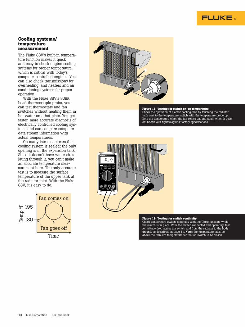
Cooling systems/ temperature measurementThe Fluke 88V’s built-in tempera-ture function makes it quick and easy to check engine cooling systems for proper temperature, which is critical with today’s computer-controlled engines. You can also check transmissions for overheating, and heaters and air conditioning systems for proper operation.
With the Fluke 88V’s 80BK bead thermocouple probe, you can test thermostats and fan switches without heating them in hot water on a hot plate. You get faster, more accurate diagnosis of electrically controlled cooling sys-tems and can compare computer data stream information with actual temperatures.
On many late model cars the cooling system is sealed; the only opening is in the expansion tank. Since it doesn’t have water circu-lating through it, you can’t make an accurate temperature mea-surement here. The only accurate test is to measure the surface temperature of the upper tank at the radiator inlet. With the Fluke 88V, it’s easy to do.
Figure 18. Testing for switch on-off temperatureCheck the operation of electric cooling fans by touching the radiator tank next to the temperature switch with the temperature probe tip. Note the temperature when the fan comes on, and again when it goes off. Check your figures against factory specifications.
Figure 19. Testing for switch continuityCheck temperature-switch continuity with the Ohms function, while the switch is in place. With the switch connected and operating, test for voltage drop across the switch and from the radiator to the body ground, as described on page 11. Note: the temperature must be above the “fan-on” temperature for the fan switch to be closed.
Fan goes off
Time
Fan comes on
195
180Tem
p °F

14 Fluke Corporation Beat the book
Fluke 115/A Automotive Multimeter KitA compact full featured digital multimeter designed for electrical systems found on today’s vehicles.
Kit includes:• Fluke 115/A • Soft carrying case• Test Leads • Back probe pins• Alligator clips • Training DVD
Fluke 179/A Automotive Multimeter KitA hybrid ready multimeter with a combination of preci-sion, features, ease-of-use, safety and reliability, includes temperature, MIN/MAX/AVG data recording.
Kit includes:• Fluke 179/A • Soft carrying case• Test leads • Back probe pins• Alligator clips • Training DVD• Thermocouple probe
Fluke 233/A Automotive Multimeter KitAn advanced hybrid ready digital multimeter with remov-able magnetic display allows you to be 30 feet away from the measurement point.
Kit includes:• Fluke 233/A • Soft carrying case• Test leads • Magnetic meter hanging strap• Alligator clips • Automotive backprobe pins• Thermocouple probe • Training DVD
Fluke 87V/A Automotive Multimeter KitA hybrid ready 4-1/2 digit, 20,000 count processor with dc and ac frequency/duty cycle for magnetic and hall-effect sensor diagnosis.
Kit includes:• Fluke 87V/A • Soft carrying case• Test leads • Magnetic meter hanging strap• Alligator clips • Automotive backprobe pins• Thermocouple probe • Training DVD
Fluke 88V Automotive MultimeterThe Fluke 88V Automotive Multimeter is designed to help automotive professionals beat the book. This DMM has more measurement functions, troubleshooting features and accuracy to solve virtually any problems on conven-tional and hybrid vehicles. Available as a stand alone meter or in a kit.
Kit includes:• Fluke 88V • Inductive RPM pickup• Heat resistant test leads • Back probe pins• Large jaw alligator clips • Insulation piercing probe• Sharp point test probes • Magnetic meter hanging strap• Temperature probe • Hard carrying case
Fluke multimeters and accessories
i410 and i1010 DC/AC Clamp-On Current Probes
i30 Low Current Clamp
C115 Soft Carrying Case
PV350 Pressure/Vacuum Module
80PK-8 Pipe Clamp Temperature Probe
80BK-A Integrated DMM Temperature Probe
80AK-A Thermocouple Adapter
TL82 Automotive Pin and Socket Adapter Set
TLK282 Deluxe Automotive Test Lead Kit
TP81and TP82 Insulation Piercing Probes
TP40 Automotive Back Probe Pin Set
TP88 Rigid Backprobe Pin Set
Fluke CorporationPO Box 9090, Everett, WA 98206 U.S.A.
Fluke Europe B.V.PO Box 1186, 5602 BD Eindhoven, The Netherlands
For more information call:In the U.S.A. (800) 443-5853 or Fax (425) 446-5116 In Europe/M-East/Africa +31 (0) 40 2675 200 or Fax +31 (0) 40 2675 222 In Canada (800)-36-FLUKE or Fax (905) 890-6866 From other countries +1 (425) 446-5500 or Fax +1 (425) 446-5116 Web access: http://www.fluke.com
©2000-2010 Fluke Corporation. Specifications subject to change without notice. Printed in U.S.A. 2/2010 1547394K A-EN-N
Modification of this document is not permitted without written permission from Fluke Corporation.
Fluke. Keeping your world up and running.®