BMI088 Data sheet - Mouser Electronics
51
BMI088: Data Sheet Document revision 1.4 Document release date September 2018 Document number BST-BMI088-DS001-14 Technical reference code 0 273 141 365 Notes Data and descriptions in this document are subject to change without notice. Product photos and pictures are for illustration purposes only and may differ from the real product appearance BMI088 6-axis Motion Tracking for High-performance Applications
Transcript of BMI088 Data sheet - Mouser Electronics

BMI088: Data Sheet
Document revision 1.4
Document release date September 2018
Document number BST-BMI088-DS001-14
Technical reference code 0 273 141 365
Notes Data and descriptions in this document are subject to change without notice. Product photos and pictures are for illustration purposes only and may differ from the real product appearance
BMI088 6-axis Motion Tracking for High-performance Applications

Bosch Sensortec | BMI088 Data sheet 2 | 50
Modifications reserved | Data subject to change without notice Document number: BST-BMI088-DS001-14
Revision_1.4_092018
Basic Description BMI088 is an inertial measurement unit (IMU) for the detection of movements and rotations in 6 degrees of freedom (6DoF). It combines the functionality of two inertial sensors in one device: an advanced triaxial 16-bit gyroscope and a versatile, leading-edge triaxial 16-bit accelerometer. BMI088 is designed to meet all requirements for high performance consumer applications in harsh vibration environments such as those encountered in drones and robotics applications. The IMU is designed to effectively suppress vibrations above a few hundred Hz that could occasionally occur due to resonances on the pcb or the structure of the total system. The sensor has an extended measurement range of up to ±24g to avoid signal clipping under strong signal exposure. An evaluation circuitry (ASIC) converts the output of the micro-electro-mechanical sensing structures (MEMS), which are developed, produced and tested in BOSCH facilities. The corresponding chip-sets are packed into one single LGA 3.0mm x 4.5mm x 0.95mm housing. For optimum system integration, BMI088 is fitted with digital interfaces (SPI or I2C), offering a wide VDDIO voltage range from 1.2V to 3.6V. To provide maximum performance and reliability, each device is tested and is ready-to-use calibrated. To increase flexibility, both gyroscope and accelerometer can not only be operated individually, but tied together for data synchronization purposes. The on-chip features comprise FIFOs for acceleration and gyroscope data and interrupt controllers. The BMI088 has an excellent temperature behavior with an outstanding low temperature coefficient of the offset (TCO) and temperature coefficient of the sensitivity (TCS).

Bosch Sensortec | BMI088 Data sheet 3 | 50
Modifications reserved | Data subject to change without notice Document number: BST-BMI088-DS001-14
Revision_1.4_092018
Index of Contents
Basic Description ...................................................................................................................................2
1. Specification ......................................................................................................................................7
1.1 Electrical Specifications ............................................................................................................. 7 Electrical Specifications: Accelerometer/Gyroscope .................................................8
1.2 Accelerometer Specifications .................................................................................................... 9
1.3 Gyroscope Specifications ........................................................................................................ 10
1.4 Temperature Sensor Specifications ......................................................................................... 11
1.5 Absolute Maximum Ratings ..................................................................................................... 12
2. Block Diagram ................................................................................................................................ 13
3. Quick Start Guide – Device Initialization ..................................................................................... 13
4. Functional Description .................................................................................................................. 14
4.1 Power Management and Power Modes .................................................................................. 14 4.1.1 Power Modes: Accelerometer ................................................................................. 14
4.1.2 Power Modes: Gyroscope ...................................................................................... 15
4.2 Sensor Data ............................................................................................................................. 15
4.3 Sensor Time............................................................................................................................. 16
4.4 Output Data Rate (ODR) and Low-pass Filter ......................................................................... 16 4.4.1 Accelerometer ......................................................................................................... 16
4.4.2 Gyroscope .............................................................................................................. 16
4.5 Range Settings ........................................................................................................................ 16
4.6 Self-test .................................................................................................................................... 16 4.6.1 Accelerometer ......................................................................................................... 17
4.6.2 Gyroscope .............................................................................................................. 17
4.7 New Data Interrupt .................................................................................................................. 18 4.7.1 Accelerometer ......................................................................................................... 18
4.7.2 Gyroscope .............................................................................................................. 18

Bosch Sensortec | BMI088 Data sheet 4 | 50
Modifications reserved | Data subject to change without notice Document number: BST-BMI088-DS001-14
Revision_1.4_092018
4.8 Soft-Reset ................................................................................................................................ 18
4.9 FIFO ......................................................................................................................................... 18
5. Register Maps ................................................................................................................................. 19
5.1 Communication with the sensor .............................................................................................. 19
5.2 Register Map: Accelerometer .................................................................................................. 20
5.3 Register Description: Accelerometer ....................................................................................... 21 5.3.1 Register 0x00: ACC_CHIP_ID ................................................................................ 21
5.3.2 Register 0x02: ACC_ERR_REG ............................................................................. 21
5.3.3 Register 0x03: ACC_STATUS ................................................................................ 21
5.3.4 Register 0x12 – 0x17: ACC data ............................................................................ 21
5.3.5 Register 0x18 – 0x1A: Sensortime data ................................................................. 22
5.3.6 Register 0x1D: ACC_INT_STAT_1 ......................................................................... 22
5.3.7 Register 0x22 – 0x23: Temperature sensor data.................................................... 22
5.3.8 Register 0x40: ACC_CONF .................................................................................... 23
5.3.9 Register 0x41: ACC_RANGE ................................................................................. 24
5.3.10 Register 0x53: INT1_IO_CONF .............................................................................. 24
5.3.11 Register 0x54: INT2_IO_CONF .............................................................................. 25
5.3.12 Register 0x58: INT1_INT2_MAP_DATA ................................................................. 25
5.3.13 Register 0x6D: ACC_SELF_TEST ......................................................................... 25
5.3.14 Register 0x7C: ACC_PWR_CONF ......................................................................... 26
5.3.15 Register 0x7D: ACC_PWR_CTRL .......................................................................... 26
5.3.16 Register 0x7E: ACC_SOFTRESET ........................................................................ 26
5.4 Register Map: Gyroscope ........................................................................................................ 27
5.5 Register Description: Gyroscope ............................................................................................. 28 5.5.1 Register 0x00: GYRO_CHIP_ID ............................................................................. 28
5.5.2 Register 0x02 – 0x07: Rate data ............................................................................ 28
5.5.3 Register 0x0A: GYRO_INT_STAT_1 ...................................................................... 28
5.5.4 Register 0x0F: GYRO_RANGE .............................................................................. 29
5.5.5 Register 0x10: GYRO_BANDWIDTH ..................................................................... 29
5.5.6 Register 0x11: GYRO_LPM1 .................................................................................. 30
5.5.7 Register 0x14: GYRO_SOFTRESET ..................................................................... 30

Bosch Sensortec | BMI088 Data sheet 5 | 50
Modifications reserved | Data subject to change without notice Document number: BST-BMI088-DS001-14
Revision_1.4_092018
5.5.8 Register 0x15: GYRO_INT_CTRL .......................................................................... 30
5.5.9 Register 0x16: INT3_INT4_IO_CONF .................................................................... 31
5.5.10 Register 0x18: INT3_INT4_IO_MAP ...................................................................... 31
5.5.11 Register 0x3C: GYRO_SELF_TEST ...................................................................... 32
6. Digital Interface............................................................................................................................... 33
6.1 Serial Peripheral Interface (SPI) .............................................................................................. 34 6.1.1 SPI interface of gyroscope part .............................................................................. 35
6.1.2 SPI interface of accelerometer part ........................................................................ 35
6.2 Inter-Integrated Circuit (I²C) ..................................................................................................... 36
7. Pin-out and Connection Diagram ................................................................................................. 41
7.1 Pin-out ..................................................................................................................................... 41
7.2 Connection diagram SPI .......................................................................................................... 42
7.3 Connection diagram I2C........................................................................................................... 42
8. Package ........................................................................................................................................... 43
8.1 Outline Dimensions ................................................................................................................. 43
8.2 Sensing axes orientation ......................................................................................................... 44
8.3 Marking .................................................................................................................................... 45 8.3.1 Mass production samples ....................................................................................... 45
8.3.2 Engineering samples .............................................................................................. 45
8.4 PCB layout and soldering guidelines ....................................................................................... 45
8.5 Handling instructions ............................................................................................................... 46
8.6 Tape and Reel specification ..................................................................................................... 46 8.6.1 Orientation within the reel ....................................................................................... 47
8.7 Environmental safety ............................................................................................................... 47 8.7.1 Halogen content ...................................................................................................... 47
9. Legal Disclaimer ............................................................................................................................. 48
9.1 Engineering samples ............................................................................................................... 48
9.2 Product use.............................................................................................................................. 48

Bosch Sensortec | BMI088 Data sheet 6 | 50
Modifications reserved | Data subject to change without notice Document number: BST-BMI088-DS001-14
Revision_1.4_092018
9.3 Application examples and hints ............................................................................................... 48
10. Document History and Modification ............................................................................................. 49

Bosch Sensortec | BMI088 Data sheet 7 | 50
Modifications reserved | Data subject to change without notice Document number: BST-BMI088-DS001-14
Revision_1.4_092018
1. Specification If not stated otherwise, the given values are over lifetime and full performance temperature and voltage ranges, minimum/maximum values are ±3σ.
1.1 Electrical Specifications
Table 1: Electrical parameter specification
Parameter Symbol Condition Min Max Unit Supply Voltage
Internal Domains VDD 2.4 3.6 V
Supply Voltage I/O Domain
VDDIO 1.2 3.6 V
Voltage Input Low Level
VIL,a SPI & I²C 0.3VDDIO -
Voltage Input High Level
VIH,a SPI & I²C 0.7VDDIO -
Voltage Output Low Level
VOL,a IOL<= 2mA, SPI 0.23VDDIO -
Voltage Output High Level
VOH IOH <= 2mA, SPI 0.8VDDIO -
Operating Temperature
TA -40 +85 °C

Bosch Sensortec | BMI088 Data sheet 8 | 50
Modifications reserved | Data subject to change without notice Document number: BST-BMI088-DS001-14
Revision_1.4_092018
Electrical Specifications: Accelerometer/Gyroscope
Table 2: Electrical parameter specification accelerometer
Parameter Symbol Condition Min Typ Max Units Total Supply Current in
Normal mode
IDD VDD = VDDIO =3.0V, 25°C, gFS4g
150 µA
Total Supply Current in
Suspend Mode
IDDsum VDD = VDDIO =3.0V, 25°C
3 µA
Power-up time ts_up Time to first valid sample from suspend
mode
1 ms
Table 3: Electrical parameter specification gyroscope
Parameter Symbol Condition Min Typ Max Unit Supply Current in
Normal Mode IDD VDD = VDDIO = 3.0V,
25°C, ODR =1kHz 5 mA
Supply Current in Suspend Mode
IDDsum VDD = VDDIO = 3.0V, 25°C
25 µA
Supply Current in Deep Suspend
Mode
IDDdsum VDD = VDDIO = 3.0V, 25°C
<5 µA
Start-up time tsu to ±1º/s of final value; from power-off
30 ms
Wake-up time twusm From suspend- and deep suspend-modes
30 ms
Wake-up time twufpm From fast power-up mode
10 ms

Bosch Sensortec | BMI088 Data sheet 9 | 50
Modifications reserved | Data subject to change without notice Document number: BST-BMI088-DS001-14
Revision_1.4_092018
1.2 Accelerometer Specifications Table 4: Accelerometer specifications
Parameter Symbol Condition Min Typ Max Units Acceleration Range gFS3g
Selectable via serial digital interface
±3 g gFS6g ±6 g gFS12g ±12 g gFS24g ±24 g
Sensitivity S3g gFS3g, TA=25°C 10920 LSB/g S6g gFS6g, TA=25°C 5460 LSB/g S12g gFS12g, TA=25°C 2730 LSB/g S24g gFS24g, TA=25°C 1365 LSB/g
Sensitivity Temperature Drift
TCS 0.002 %/K
Zero-g Offset Off Nominal VDD and VDDIO, 25°C, gFS6g
20 mg
Zero-g Offset Temperature Drift
TCO <0.2 mg/K
Output Data Rate ODR 12.5 1600 Hz
Bandwidth range BW 3dB cut-off frequency of the accelerometer
depends on ODR and OSR
5 280 (245 for Z axis)
Hz
Nonlinearity NL best fit straight line, gFS3g 0.5 %FS Output Noise
Density nrms gFS3g, TA=25°C
Nominal VDD supplies Normal mode
190 (Z-axis)
160
(X- & Y- axis)
µg/√Hz
Cross Axis Sensitivity
S relative contribution between any two of the
three axes
0.5 %
Alignment Error EA relative to package outline 0.5 °

Bosch Sensortec | BMI088 Data sheet 10 | 50
Modifications reserved | Data subject to change without notice Document number: BST-BMI088-DS001-14
Revision_1.4_092018
1.3 Gyroscope Specifications Table 5: Gyroscope specifications
Parameter Symbol Condition Min Typ Max Unit
Range RFS125
Selectable via serial digital interface
125 °/s
RFS250 250 °/s
RFS500 500 °/s
RFS1000 1000 °/s
RFS2000 2000 °/s
Sensitivity
Ta=25°C, RFS125 262.144 LSB/°/s
Ta=25°C, RFS250 131.072 LSB/°/s
Ta=25°C, RFS500 65.536 LSB/°/s
Ta=25°C, RFS1000 32.768 LSB/°/s
Ta=25°C, RFS2000 16.384 LSB/°/s
Sensitivity tolerance
Ta=25°C, RFS2000 ±1 %
Sensitivity Change over Temperature
TCS Nominal VDD supplies -40°C ≤ TA ≤ +85°C
RFS2000
±0.03 %/K
Sensitivity Supply Volt. Drift
SVDD TA=25°C, VDDmin ≤ VDD ≤ VDDmax
<0.4 %/V
Nonlinearity NL best fit straight line RFS1000, RFS2000
±0.05 %FS
g-Sensitivity Sensitivity to acceleration stimuli in
all three axis (frequency <20kHz)
0.1 °/s/g
Zero-rate Offset Off Ωx Ωy
and Ωz Nominal VDD supplies TA=25°C, slow and fast offset cancellation off
±1 °/s
Zero-rate Offset Change over Temperature
TCO Nominal VDD supplies -40°C ≤ TA ≤ +85°C
RFS2000
±0.015 °/s per K
Zero-rate Offset Supply Volt. Drift
OffΩ VDD TA=25°C, VDDmin ≤ VDD ≤ VDDmax
<0.1 °/s /V
Output Noise nrms rms, BW=47Hz (@ 0.014°/s/√Hz)
0.1 °/s

Bosch Sensortec | BMI088 Data sheet 11 | 50
Modifications reserved | Data subject to change without notice Document number: BST-BMI088-DS001-14
Revision_1.4_092018
Bandwidth BW f-3dB 523 230 116 64 47 32 23 12
Hz
Data rate (set of x,y,z rate)
2000 1000 400 200 100
Hz
Data rate tolerance (set of x,y,z rate)
±0.3 %
Cross Axis Sensitivity
Sensitivity to stimuli in non-sense-direction
±1 %
1.4 Temperature Sensor Specifications Table 6: Temperature sensor specifications
Parameter Symbol Condition Min Typ Max Units Temperature Sensor Measurement Range
TS -104 150 °C
Temperature Sensor Slope
dTS 0.125 K/LSB
Temperature Sensor Offset error
OTS at 25°C ±1 K

Bosch Sensortec | BMI088 Data sheet 12 | 50
Modifications reserved | Data subject to change without notice Document number: BST-BMI088-DS001-14
Revision_1.4_092018
1.5 Absolute Maximum Ratings Table 7: Absolute maximum ratings
Parameter Condition Min Max Units
Voltage at Supply Pin
VDD Pin -0.3 4 V
VDDIO Pin -0.3 4 V
Voltage at any Logic Pin Non-Supply Pin -0.3 VDDIO+0.3 V
Passive Storage Temp. Range ≤ 65% rel. H. -50 +150 °C
Mechanical Shock
Duration ≤ 200µs 10,000 g
Duration ≤ 1.0ms 2,000 g
Free fall onto hard surfaces
1.8 m
ESD HBM, at any Pin 2 kV
CDM 500 V
MM 200 V Note: Stress above these limits may cause damage to the device. Exceeding the specified electrical limits may affect the device reliability or cause malfunction.

Bosch Sensortec | BMI088 Data sheet 13 | 50
Modifications reserved | Data subject to change without notice Document number: BST-BMI088-DS001-14
Revision_1.4_092018
2. Block Diagram
Figure 1 shows the basic building blocks of the BMI088:
Figure 1: Block diagram of BMI088
3. Quick Start Guide – Device Initialization
For a proper device initialization, the following steps should be considered: • The user must decide on the interface (I2C or SPI) already during HW design: with the PS pin
the user determines which interface the sensor should listen to (see chapter 6). • The gyroscope part of the BMI088 initializes its I/O pins according to the selection given by the
PS pin. • The accelerometer part starts in I2C mode. It will stay in I2C mode until it detects a rising edge
on the CSB1 pin (chip select of the accelerometer), on which the accelerometer part switches to SPI mode and stays in this mode until the next power-up-reset.
• To change the accelerometer to SPI mode in the initialization phase, the user could perform a dummy SPI read operation, e.g. of register ACC_CHIP_ID (the obtained value will be invalid).
After the POR the gyroscope is in normal mode, while the accelerometer is in suspend mode. To switch the accelerometer into normal mode, the user must perform the following steps:
a. Power up the sensor b. Wait 1 ms c. Enter normal mode by writing ‘4’ to ACC_PWR_CTRL d. Wait for 50 ms

Bosch Sensortec | BMI088 Data sheet 14 | 50
Modifications reserved | Data subject to change without notice Document number: BST-BMI088-DS001-14
Revision_1.4_092018
4. Functional Description
4.1 Power Management and Power Modes The BMI088 has two distinct power supply pins:
• VDD is the main power supply for the internal blocks • VDDIO is a separate power supply pin mainly used for the supply of the interface
There are no limitations on the voltage levels of both pins relative to each other, as long as each of them lies within its operating range. Furthermore, the device can be completely switched off (VDD = 0V) while keeping the VDDIO supply on (VDDIO > 0V) or vice versa. When the VDDIO supply is switched off, all interface pins (CSB, SDI, SCK, PS) must be kept close to GNDIO potential. The device contains a power-on reset (POR) generator. It resets the logic part and the register values after powering-on VDD and VDDIO. This means that all application specific settings which are not equal to the default settings (refer to 6.2 register map accelerometer and to 8.2 register map gyroscope), must be changed back to their designated values after POR. Please note: the POR resets also the interface. For the gyroscope part, the interface is defined by the voltage level on the PS pin. The interface of the accelerometer part is defined by the voltage level of the CSB1 pin at the moment when the POR is initiated (see chapter 3).
4.1.1 Power Modes: Accelerometer The power state of the BMI088 accelerometer is controlled through the register ACC_PWR_CTRL. The register ACC_PWR_CTRL enables and disables the accelerometer and the temperature sensor. To enter normal mode, the value 0x04 must be written to ACC_PWR_CTRL. To enter suspend mode, register ACC_PWR_CTRL must be cleared. Note: the sensor is in suspend mode after reset (POR or soft-reset), thus the user actively needs to enter normal mode in order to obtain acceleration values. Note: after POR or soft-reset, the acceleration sensor needs up to 1ms boot time. When changing power modes, the sensor needs up to 5ms to settle. Any communication with the sensor during this time should be avoided.

Bosch Sensortec | BMI088 Data sheet 15 | 50
Modifications reserved | Data subject to change without notice Document number: BST-BMI088-DS001-14
Revision_1.4_092018
4.1.2 Power Modes: Gyroscope The gyroscope has 3 different power modes. Besides normal mode, which represents the fully operational state of the device, there are 2 energy saving modes: suspend mode and deep-suspend mode. After power-up gyro is in normal mode so that all parts of the device are held powered-up and data acquisition is performed continuously. In suspend mode the whole analog part is powered down. No data acquisition is performed. While in suspend mode the latest rate data and the content of all configuration registers are kept. The registers can still be read (though they are not updated). Suspend mode is entered by writing 0x80 to the register GYRO_LPM1. It can be left by writing 0x00 to GYRO_LPM1 or by a soft reset (see 4.8). Although write access to registers is supported at the full interface clock speed (SCL or SCK), a waiting period must be inserted between two consecutive write cycles (please refer also to section 9.2.1). In deep suspend mode the device reaches the lowest possible power consumption. Only the interface section is kept alive. No data acquisition is performed and the content of the configuration registers is lost. Deep suspend mode is entered by writing 0x20 to the register GYRO_LPM1. It can be left by writing 0x00 to GYRO_LPM1 or by a soft reset (see 4.8). Please note, that all application specific settings, which are not equal to the default settings, must be re-set to its designated values after leaving deep-suspend mode. Note: after POR or soft-reset, or when switching between the different power modes, the gyroscope sensor needs up to 30ms time to reach the new state. Any communication with the sensor during this time should be avoided.
4.2 Sensor Data The width of the gyroscope and accelerometer sensor data is 16 bits (11 bits for the temperature sensor) given in two’s complement representation. The bits for each axis are split into an MSB upper part and an LSB lower part. Reading the sensor data registers shall always start with the LSB part. In order to ensure the integrity of the sensor data, the content of an MSB register is locked by reading the corresponding LSB register (shadowing procedure). For details regarding the registers and the interpretation of the data found in these registers see:
• chapter 5.5.2 for the gyroscope part • chapter 5.3.4 or the accelerometer part • chapter 5.3.7 for the temperature sensor
The burst-access mechanism provides an efficient way to read out the angular rate data in I2C or SPI mode. During a burst-access, the sensor automatically increments the starting read address after each byte. The burst-access allows data to be transferred over the I2C bus with an up to 50% reduced data density. The sensor data (angular rate or acceleration data) in all read-out registers is locked as long as the burst read access is active. Reading the sensor data registers of each gyroscope and accelerometer part in burst read access mode ensures that the sensor values in all readout registers belong to the same sample.
Bosch Sensortec | BMI088 Data sheet 16 | 50
Modifications reserved | Data subject to change without notice Document number: BST-BMI088-DS001-14
Revision_1.4_092018
4.3 Sensor Time The accelerometer part of BMI088 has a built-in counter with a width of 24 bits. It increments periodically with a resolution of 39.0625µs. Details can be found in chapter 5.3.5.
4.4 Output Data Rate (ODR) and Low-pass Filter The sensor signals from the acceleration sensor and gyroscope analog front-end are each routed through a low-pass filter.
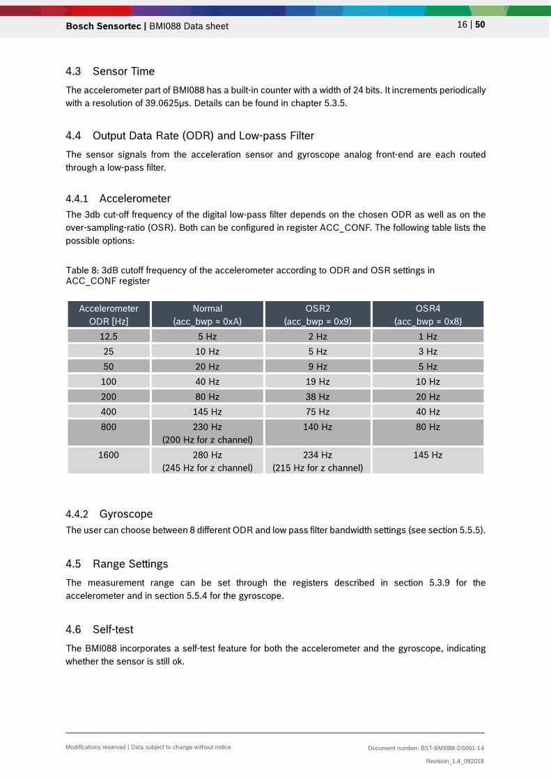
4.4.1 Accelerometer The 3db cut-off frequency of the digital low-pass filter depends on the chosen ODR as well as on the over-sampling-ratio (OSR). Both can be configured in register ACC_CONF. The following table lists the possible options:
Table 8: 3dB cutoff frequency of the accelerometer according to ODR and OSR settings in ACC_CONF register
Accelerometer ODR [Hz]
Normal (acc_bwp = 0xA)
OSR2 (acc_bwp = 0x9)
OSR4 (acc_bwp = 0x8)
12.5 5 Hz 2 Hz 1 Hz 25 10 Hz 5 Hz 3 Hz 50 20 Hz 9 Hz 5 Hz 100 40 Hz 19 Hz 10 Hz 200 80 Hz 38 Hz 20 Hz 400 145 Hz 75 Hz 40 Hz 800 230 Hz
(200 Hz for z channel) 140 Hz
80 Hz
1600 280 Hz (245 Hz for z channel)
234 Hz (215 Hz for z channel)
145 Hz
4.4.2 Gyroscope The user can choose between 8 different ODR and low pass filter bandwidth settings (see section 5.5.5).
4.5 Range Settings The measurement range can be set through the registers described in section 5.3.9 for the accelerometer and in section 5.5.4 for the gyroscope.
4.6 Self-test The BMI088 incorporates a self-test feature for both the accelerometer and the gyroscope, indicating whether the sensor is still ok.

Bosch Sensortec | BMI088 Data sheet 17 | 50
Modifications reserved | Data subject to change without notice Document number: BST-BMI088-DS001-14
Revision_1.4_092018
4.6.1 Accelerometer The self-test feature allows for checking the sensor functionality by applying electrostatic forces to the sensor core instead of external accelerations. By physically deflecting the seismic mass, the entire signal path of the sensor is tested. Activation of the self-test results in a static offset in the acceleration data. Any external acceleration or gravitational force, which is applied to the sensor during a self-test, will be observed in the sensor output as a superposition of the acceleration and the self-test signal. This means that the self-test signal depends on the orientation of the sensor. To overcome this, the full self-test procedure should be performed under static circumstances, e.g. when the part is not excited to any acceleration except gravity. The recommended self-test procedure is as follows: 1) Set ±24g range by writing 0x03 to register ACC_RANGE (0x41) 2) Set ODR=1.6kHz, continuous sampling mode, “normal mode” (norm_avg4) by writing 0xA7 to
register ACC_CONF (0x40) • Continuous filter function: set bit7 in ACC_CONF • “normal avg4 mode”: ACC_CONF |= 0x02<<4 • ODR=1.6kHz: ACC_CONF |= 0x0C
3) Wait for > 2 ms 4) Enable the positive self-test polarity (i.e. write 0x0D to register ACC_SELF_TEST (0x6D)) 5) Wait for > 50ms 6) Read the accelerometer offset values for each axis (positive self-test response) 7) Enable the negative self-test polarity (i.e. write 0x09 to register ACC_SELF_TEST (0x6D)) 8) Wait for > 50ms 9) Read the accelerometer offset values for each axis (negative self-test response) 10) Disable the self-test (i.e. write 0x00 to register ACC_SELF_TEST (0x6D)) 11) Calculate difference of positive and negative self-test response and compare with the expected
values (see table below) 12) Wait for > 50ms to let the sensor settle to normal mode steady state operation
Table 9: Accelerometer self-test: resulting minimum difference signal between positive and negative self-test signal
x-axis signal y-axis signal z-axis signal
≥1000 mg ≥1000 mg ≥500 mg It is recommended to perform a reset of the device after a self-test has been performed, since the self-test response also affects the interrupt generation. If the reset cannot be performed, the following sequence must be kept to prevent unwanted interrupt generation: disable interrupts, change parameters of interrupts, wait for at least 50ms, and enable desired interrupts.
4.6.2 Gyroscope A built-in self-test facility of the gyro does not deflect the mechanical MEMS structure (as the accelerometer self-test does), but this test also provides a quick way to determine if the gyroscope is operational within the specified conditions.
To trigger the self-test, bit #0 (‘bite_trig’) in address GYRO_SELF_TEST must be set. When the test is finished, bit #1 (‘bist_rdy’) will be set by the gyro and the test result can then be found in bit #2 (‘bist_fail’). A ‘0’ indicates that the test was passed without issues. If a failure occurred, the bit ‘bist_fail’ will be set to ‘1’. A further test which is running continuously in the background can be checked by reading bit #4 in address GYRO_SELF_TEST. Proper sensor function is indicated if the bit is set to ‘1’.

Bosch Sensortec | BMI088 Data sheet 18 | 50
Modifications reserved | Data subject to change without notice Document number: BST-BMI088-DS001-14
Revision_1.4_092018
4.7 New Data Interrupt Both accelerometer and gyroscope part offer a new data ready interrupt, which fires whenever a new data sample set is complete and made available in the corresponding sensor data registers. This allows a low latency data readout.
4.7.1 Accelerometer The new data interrupt flag can be found in the register ACC_INT_STAT_1 (bit #7). It is set whenever new data is available in the data registers and cleared automatically. The interrupt can be mapped to the interrupt pins INT1 and/or INT2 in register INT1_INT2_MAP_DATA. Both interrupt pins INT1 and INT2 can be configured regarding their electrical behavior (see INT1_IO_CONF and INT2_IO_CONF).
4.7.2 Gyroscope The gyroscope provides a new data interrupt, which will generate an interrupt every time after storing a new value of z-axis angular rate data in the data register. The interrupt is cleared automatically after 280-400 µs. In contrast to the accelerometer part, for the gyro the new data interrupt must be explicitly enabled by writing 0x80 to the register GYRO_INT_CTRL. The interrupt can be mapped to the interrupt pins INT3 and/or INT4 in register INT3_INT4_IO_MAP. Both interrupt pins INT3 and INT4 can be configured regarding their electrical behavior (see INT3_INT4_IO_CONF).
4.8 Soft-Reset A soft-reset can be initiated at any time
• for the accelerometer part by writing the command soft-reset (0xB6) to register ACC_SOFTRESET (see 5.3.16)
• for the gyroscope part by writing the command soft-reset (0xB6) to register GYRO_SOFTRESET (see 5.5.7)
The soft-reset performs a fundamental reset to the device, which is largely equivalent to a power cycle. Following a delay, all user configuration settings are overwritten with their default state wherever applicable.
4.9 FIFO
BMI088 offers two integrated FIFO (First In, First Out) buffers for accelerometer and gyroscope sensor signals, helping the user to reduce or even omit time critical read access to the sensor in order to obtain data with a high timing precision.
For details, refer the Application Note: BMI08x FIFO Usage

Bosch Sensortec | BMI088 Data sheet 19 | 50
Modifications reserved | Data subject to change without notice Document number: BST-BMI088-DS001-14
Revision_1.4_092018
5. Register Maps
5.1 Communication with the sensor The entire communication with the device is performed by reading from and writing to registers. Registers have a width of 8 bits; they are mapped to an 8-bit address space. Accelerometer and gyroscope have individual register maps. The selection of the appropriate register map is done on digital interface level by either selecting the corresponding chip select pin (SPI mode) or I2C address (I2C mode). For details regarding the digital interface, see chapter 0. The functional registers and the register addresses containing functional bits are marked in the following register maps. All non-functional registers are marked as reserved and should be completely ignored by the user. It is recommended to mask out (logical and with zero) non-functional bits (marked with ‘-‘) of registers which partially contain functional bits (i.e. read the register content first, changing bit by means of bit-wise operations, and write the modified byte back to the register). Meaning of colors in the register maps:
read/write read only write only
Bosch Sensortec | BMI088 Data sheet 20 | 50
Modifications reserved | Data subject to change without notice Document number: BST-BMI088-DS001-14
Revision_1.4_092018
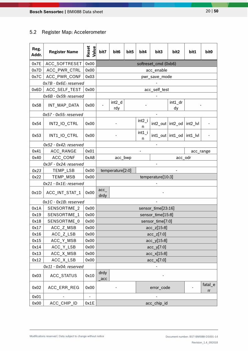
5.2 Register Map: Accelerometer
Reg. Addr. Register Name
Res
et
Valu
e
bit7 bit6 bit5 bit4 bit3 bit2 bit1 bit0
0x7E ACC_SOFTRESET 0x00 softreset_cmd (0xb6) 0x7D ACC_PWR_CTRL 0x00 acc_enable 0x7C ACC_PWR_CONF 0x03 pwr_save_mode
0x7B - 0x6E: reserved - 0x6D ACC_SELF_TEST 0x00 acc_self_test
0x6B - 0x59: reserved -
0x58 INT_MAP_DATA 0x00 - int2_drdy - int1_dr
dy -
0x57 - 0x55: reserved -
0x54 INT2_IO_CTRL 0x00 - int2_i
n int2_out int2_od int2_lvl -
0x53 INT1_IO_CTRL 0x00 - int1_in
int1_out int1_od int1_lvl -
0x52 - 0x42: reserved - 0x41 ACC_RANGE 0x01 - acc_range 0x40 ACC_CONF 0xA8 acc_bwp acc_odr
0x3F - 0x24: reserved - 0x23 TEMP_LSB 0x00 temperature[2:0] - 0x22 TEMP_MSB 0x00 temperature[10:3]
0x21 - 0x1E: reserved -
0x1D ACC_INT_STAT_1 0x00 acc_drdy -
0x1C - 0x1B: reserved - 0x1A SENSORTIME_2 0x00 sensor_time[23:16] 0x19 SENSORTIME_1 0x00 sensor_time[15:8] 0x18 SENSORTIME_0 0x00 sensor_time[7:0] 0x17 ACC_Z_MSB 0x00 acc_z[15:8] 0x16 ACC_Z_LSB 0x00 acc_z[7:0] 0x15 ACC_Y_MSB 0x00 acc_y[15:8] 0x14 ACC_Y_LSB 0x00 acc_y[7:0] 0x13 ACC_X_MSB 0x00 acc_x[15:8] 0x12 ACC_X_LSB 0x00 acc_x[7:0]
0x11 - 0x04: reserved -
0x03 ACC_STATUS 0x10 drdy_acc
-
0x02 ACC_ERR_REG 0x00 - error_code - fatal_e
rr 0x01 - - - 0x00 ACC_CHIP_ID 0x1E acc_chip_id
Bosch Sensortec | BMI088 Data sheet 21 | 50
Modifications reserved | Data subject to change without notice Document number: BST-BMI088-DS001-14
Revision_1.4_092018
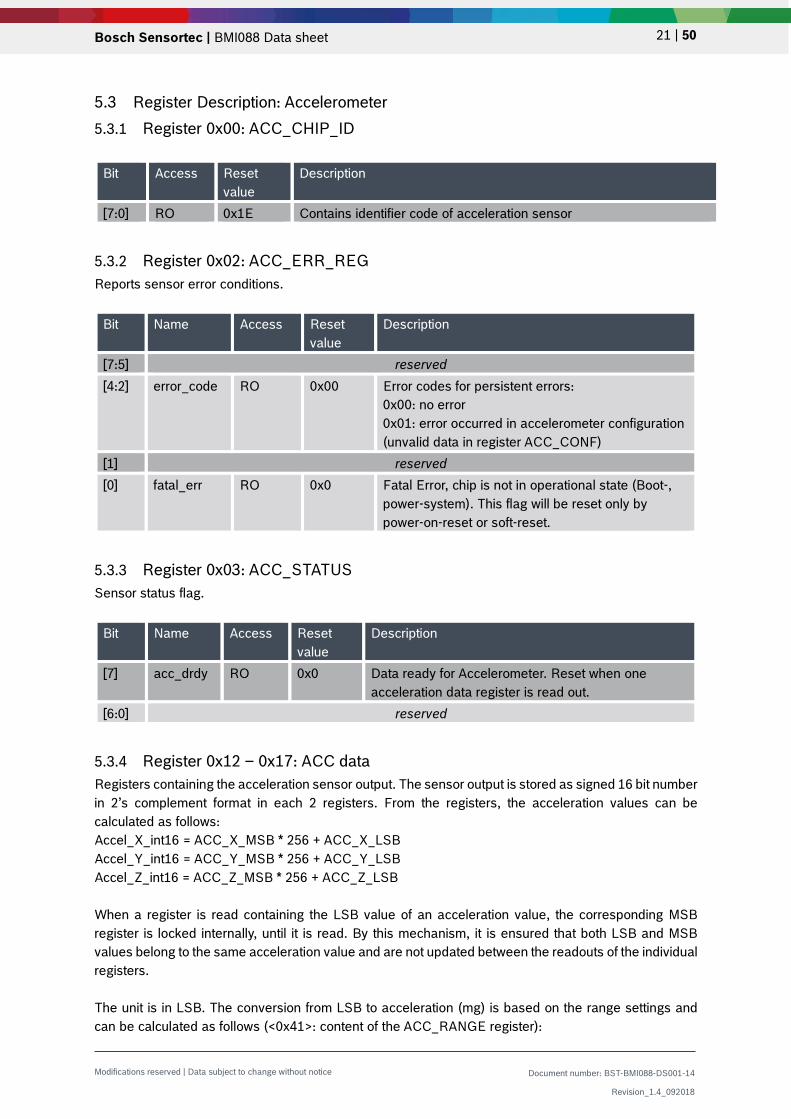
5.3 Register Description: Accelerometer 5.3.1 Register 0x00: ACC_CHIP_ID
Bit Access Reset value
Description
[7:0] RO 0x1E Contains identifier code of acceleration sensor
5.3.2 Register 0x02: ACC_ERR_REG Reports sensor error conditions.
Bit Name Access Reset value
Description
[7:5] reserved [4:2] error_code RO 0x00 Error codes for persistent errors:
0x00: no error 0x01: error occurred in accelerometer configuration (unvalid data in register ACC_CONF)
[1] reserved [0] fatal_err RO 0x0 Fatal Error, chip is not in operational state (Boot-,
power-system). This flag will be reset only by power-on-reset or soft-reset.
5.3.3 Register 0x03: ACC_STATUS Sensor status flag.
Bit Name Access Reset value
Description
[7] acc_drdy RO 0x0 Data ready for Accelerometer. Reset when one acceleration data register is read out.
[6:0] reserved
5.3.4 Register 0x12 – 0x17: ACC data Registers containing the acceleration sensor output. The sensor output is stored as signed 16 bit number in 2’s complement format in each 2 registers. From the registers, the acceleration values can be calculated as follows: Accel_X_int16 = ACC_X_MSB * 256 + ACC_X_LSB Accel_Y_int16 = ACC_Y_MSB * 256 + ACC_Y_LSB Accel_Z_int16 = ACC_Z_MSB * 256 + ACC_Z_LSB When a register is read containing the LSB value of an acceleration value, the corresponding MSB register is locked internally, until it is read. By this mechanism, it is ensured that both LSB and MSB values belong to the same acceleration value and are not updated between the readouts of the individual registers. The unit is in LSB. The conversion from LSB to acceleration (mg) is based on the range settings and can be calculated as follows (<0x41>: content of the ACC_RANGE register):

Bosch Sensortec | BMI088 Data sheet 22 | 50
Modifications reserved | Data subject to change without notice Document number: BST-BMI088-DS001-14
Revision_1.4_092018
Accel_X_in_mg = Accel_X_int16 / 32768 * 1000 * 2^(<0x41> + 1) * 1.5 Accel_Y_in_mg = Accel_Y_int16 / 32768 * 1000 * 2^(<0x41> + 1) * 1.5 Accel_Z_in_mg = Accel_Z_int16 / 32768 * 1000 * 2^(<0x41> + 1) * 1.5
5.3.5 Register 0x18 – 0x1A: Sensortime data Registers containing the value of the internal 24-bit counter.
• Register 0x18 (SENSORTIME_0) contains the lower 8 bits of the counter. This register is incremented every 39.0625 µs.
• Register 0x19 (SENSORTIME_1) contains the middle 8 bits of the counter. This register is incremented on SENSORTIME_0 overflow, which is every 10 ms.
• Register 0x1A (SENSORTIME_2) contains the higher 8 bits of the counter. This register is incremented on SENSORTIME_1 overflow, which is every 2.56 s.
The complete 24-bit counter overflows after 655.36 s or almost 11 minutes.
5.3.6 Register 0x1D: ACC_INT_STAT_1 Interrupt status register.
Bit Name Access Reset value
Description
[7] acc_drdy RO 0x00 Acceleration data ready interrupt. Cleared on read of this register
[6:0] reserved
5.3.7 Register 0x22 – 0x23: Temperature sensor data Registers containing the temperature sensor data output. The data is stored in an 11-bit value in 2’s complement format. The resolution is 0.125°C/LSB, thus the temperature can be obtained as follows: Temp_uint11 = (TEMP_MSB * 8) + (TEMP_LSB / 32) if Temp_uint11 > 1023: Temp_int11 = Temp_uint11 – 2048 else:
Temp_int11 = Temp_uint11 Temperature = Temp_int11 * 0,125°C/LSB + 23°C
TEMP_MSB TEMP_LSB Temp_int11 Temperature 0x3E 0x00 496 85 °C
… … … … 0x00 0x60 3 23.375 °C 0x00 0x40 2 23.250 °C 0x00 0x20 1 23.125 °C 0x00 0x00 0 23.0°C
… … … … 0xC1 0x00 -504 -40 °C 0x80 Invalid
The temperature sensor data is updated every 1.28 s.

Bosch Sensortec | BMI088 Data sheet 23 | 50
Modifications reserved | Data subject to change without notice Document number: BST-BMI088-DS001-14
Revision_1.4_092018
5.3.8 Register 0x40: ACC_CONF Accelerometer configuration register.
Bit Name Access Reset value
Description
[7:4] acc_bwp RW 0x0A This parameter influences the bandwidth of the accelerometer low pass filter. For details, see section 4.4.1. Possible values:
acc_bwp Filter setting
0x08 OSR4 (4-fold oversampling)
0x09 OSR2 (2-fold oversampling)
0x0A Normal
others reserved
[3:0] acc_odr RW 0x08 This parameter sets the output data rate ODR.
Possible values:
acc_odr ODR in Hz 0x00 – 0x04 reserved
0x05 12.5
0x06 25
0x07 50
0x08 100
0x09 200
0x0A 400
0x0B 800
0x0C 1600
0x0D – 0X0F reserved

Bosch Sensortec | BMI088 Data sheet 24 | 50
Modifications reserved | Data subject to change without notice Document number: BST-BMI088-DS001-14
Revision_1.4_092018
5.3.9 Register 0x41: ACC_RANGE Accelerometer range setting register.
Bit Name Access Reset value
Description
[7:2] reserved [1:0] acc_range RW 0x01 This parameter sets the measurement range.
Possible values:
acc_range Range setting 0x00 ±3g
0x01 ±6g
0x02 ±12g
0x03 ±24g
5.3.10 Register 0x53: INT1_IO_CONF Configures the input/output pin INT1.
Bit Name Access Reset value
Description
[7:5] reserved [4] int1_in RW 0x00 Enable INT1 as input pin. [3] int1_out RW 0x00 Enable INT1 as output pin. [2] int1_od RW 0x00
int1_od Pin behavior 0x00 Push-pull
0x01 Open-drain
[1] int1_lvl RW 0x00
int1_lvl Active state
0x00 Active low
0x01 Active high
[0] reserved

Bosch Sensortec | BMI088 Data sheet 25 | 50
Modifications reserved | Data subject to change without notice Document number: BST-BMI088-DS001-14
Revision_1.4_092018
5.3.11 Register 0x54: INT2_IO_CONF Configures the input/output pin INT2.
Bit Name Access Reset value
Description
[7:5] reserved [4] int2_io RW 0x00 Enable INT2 as input pin. [3] int2_out RW 0x00 Enable INT2 as output pin. [2] int2_od RW 0x00
int2_od Pin behavior 0x00 Push-pull
0x01 Open-drain
[1] int2_lvl RW 0x00
int2_lvl Active state 0x00 Active low
0x01 Active high
[0] reserved
5.3.12 Register 0x58: INT1_INT2_MAP_DATA Map data ready interrupt to output pin INT1 and/or INT2.
Bit Name Access Reset value
Description
[7] reserved [6] Int2_drdy RW 0x00 Map data ready interrupt to pin INT2 [5:3] reserved [2] Int1_drdy RW 0x00 Map data ready interrupt to pin INT1 [1:0] reserved
5.3.13 Register 0x6D: ACC_SELF_TEST Enables the sensor self-test signal, occurring as a steady offset to the sensor output. Note that the self-test needs to be switched off actively by the user (details see 4.6.1).
Bit Access Reset value
Description
[7:0] RW 0x00 self_test Behaviour
0x00 Self-test is switched off.
0x0D Enable positive self-test signal.
0x09 Enable negative self-test signal.

Bosch Sensortec | BMI088 Data sheet 26 | 50
Modifications reserved | Data subject to change without notice Document number: BST-BMI088-DS001-14
Revision_1.4_092018
5.3.14 Register 0x7C: ACC_PWR_CONF Switches accelerometer into suspend mode for saving power. In this mode the data acquisition is stopped.
Bit Name Access Reset value
Description
[7:0] acc_pwr_save RW 0x03 acc_pwr_save Filter setting
0x03 Suspend mode
0x00 Active mode
5.3.15 Register 0x7D: ACC_PWR_CTRL Switches accelerometer ON or OFF. Required to do after every reset in order to obtain acceleration values.
Bit Name Access Reset value
Description
[7:0] acc_enable RW 0x00 acc_enable Filter setting
0x00 Accelerometer off
0x04 Accelerometer on
5.3.16 Register 0x7E: ACC_SOFTRESET
Bit Access Reset value
Description
[7:0] W N/A Writing a value of 0xB6 to this register resets the sensor. (Do not write any other content to this register.) Following a delay of 1 ms, all configuration settings are overwritten with their reset value. The soft-reset can be triggered from any operation mode.

Bosch Sensortec | BMI088 Data sheet 27 | 50
Modifications reserved | Data subject to change without notice Document number: BST-BMI088-DS001-14
Revision_1.4_092018
5.4 Register Map: Gyroscope
Reg
. A
ddr.
Register name
Res
et
valu
e bit7 bit6 bit5 bit4 bit3 bit2 bit1 bit0
0x3F - 0x3D: reserved - 0x3C
GYRO_SELF_TEST N/A - rate_ok - bist_fail bist_rdy trig_bist
0x3B - 0x19: reserved - 0x18
INT3_INT4_IO_MAP
0x00 int3_int4_io_map
0x17: reserved - 0x16
INT3_INT4_IO_CONF
0x0F
- Int4_od
Int4_lvl Int3_od Int3_lvl
0x15 GYRO_INT_CTRL
0x00 gyro_int_ctrl
0x14
GYRO_SOFTRESET N/A
softreset
0x13 - 0x12: reserved -
0x11 GYRO_LPM1 0x00 gyro_pm
0x10
GYRO_BANDWIDTH
0x80 gyro_bw
0x0F GYRO_RANGE
0x00 gyro_range
0x0E - 0x0B: reserved - 0x0A
GYRO_INT_STAT_1 N/A gyro_drdy -
0x09 - 0x08: reserved - 0x07 RATE_Z_MSB N/A
rate_z[15:8]
0x06 RATE_Z_LSB N/A rate_z[7:0]
0x05 RATE_Y_MSB N/A
rate_y[15:8]
0x04 RATE_Y_LSB N/A rate_y[7:0]
0x03 RATE_X_MSB N/A
rate_x[15:8]
0x02 RATE_X_LSB N/A rate_x[7:0]
0x01 Reserved N/A
-
0x00 GYRO_CHIP_ID
0x0F gyro_chip_id

Bosch Sensortec | BMI088 Data sheet 28 | 50
Modifications reserved | Data subject to change without notice Document number: BST-BMI088-DS001-14
Revision_1.4_092018
5.5 Register Description: Gyroscope 5.5.1 Register 0x00: GYRO_CHIP_ID
Bit Access Reset value
Description
[7:0] RO 0x0F Contains identifier code of gyroscope.
5.5.2 Register 0x02 – 0x07: Rate data Registers containing the angular velocity sensor output. The sensor output is stored as signed 16-bit number in 2’s complement format in each 2 registers. From the registers, the gyro values can be calculated as follows: Rate_X: RATE_X_MSB * 256 + RATE_X_LSB Rate_Y: RATE_Y_MSB * 256 + RATE_Y_LSB Rate_Z: RATE_Z_MSB * 256 + RATE_Z_LSB When a register is read containing the LSB value of a rate value, the corresponding MSB register is locked internally, until it is read. By this mechanism, it is ensured that both LSB and MSB values belong to the same rate range value and are not updated between the readouts of the individual registers. The unit is in LSB. The conversion from LSB to angular velocity (degree per second) is based on the range settings (see 5.5.4). For example, for the default range setting of 0x00 in register 0x0F, the following conversion table applies:
Sensor output [LSB] Angular rate (in 2000°/s range mode) +32767 + 2000°/s
… … 0 0°/s … …
-32767 - 2000°/s
5.5.3 Register 0x0A: GYRO_INT_STAT_1
Bit Name Access Reset value
Description
[7] gyro_drdy RO N/A Data ready interrupt status. The interrupt is cleared automatically after 280-400 µs.
Bosch Sensortec | BMI088 Data sheet 29 | 50
Modifications reserved | Data subject to change without notice Document number: BST-BMI088-DS001-14
Revision_1.4_092018
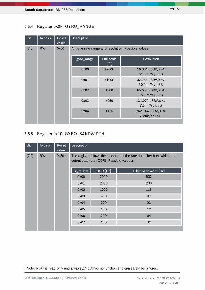
5.5.4 Register 0x0F: GYRO_RANGE
Bit Access Reset value
Description
[7:0] RW 0x00 Angular rate range and resolution. Possible values:
gyro_range Full scale [°/s]
Resolution
0x00 ±2000 16.384 LSB/°/s 61.0 m°/s / LSB
0x01 ±1000 32.768 LSB/°/s 30.5 m°/s / LSB
0x02 ±500 65.536 LSB/°/s 15.3 m°/s / LSB
0x03 ±250 131.072 LSB/°/s 7.6 m°/s / LSB
0x04 ±125 262.144 LSB/°/s 3.8m°/s / LSB
5.5.5 Register 0x10: GYRO_BANDWIDTH
Bit Access Reset value
Description
[7:0] RW 0x801 The register allows the selection of the rate data filter bandwidth and output data rate (ODR). Possible values:
gyro_bw ODR [Hz] Filter bandwidth [Hz] 0x00 2000 532
0x01 2000 230
0x02 1000 116
0x03 400 47
0x04 200 23
0x05 100 12
0x06 200 64
0x07 100 32
1 Note: bit #7 is read-only and always ‚1‘, but has no function and can safely be ignored.

Bosch Sensortec | BMI088 Data sheet 30 | 50
Modifications reserved | Data subject to change without notice Document number: BST-BMI088-DS001-14
Revision_1.4_092018
5.5.6 Register 0x11: GYRO_LPM1 Selection of the main power modes. Please note that only switching between normal mode and the suspend modes is allowed, it is not possible to switch between suspend and deep suspend and vice versa.
Bit Access Reset value
Description
[7:0] RW 0x00 Switch to the main power modes.
gyro_pm Power mode
0x00 normal
0x80 suspend
0x20 deep suspend
5.5.7 Register 0x14: GYRO_SOFTRESET
Bit Access Reset value
Description
[7:0] W N/A Writing a value of 0xB6 to this register resets the sensor. (Other values are ignored.) Following a delay of 30 ms, all configuration settings are overwritten with their reset value. The soft reset can be triggered from any operation mode.
5.5.8 Register 0x15: GYRO_INT_CTRL
Bit Access Reset value
Description
[7:0] RW 0x00 gyro_int_ctrl Behavior
0x00 No data ready interrupt is triggered
0x80 Enables the new data interrupt to be triggered on new data. See section Gyroscope for mapping
the interrupt to an interrupt pin.

Bosch Sensortec | BMI088 Data sheet 31 | 50
Modifications reserved | Data subject to change without notice Document number: BST-BMI088-DS001-14
Revision_1.4_092018
5.5.9 Register 0x16: INT3_INT4_IO_CONF Sets electrical and logical properties of the interrupt pins.
Bit Name Access Reset value
Description
[3] Int4_od RW ‘0’
Int4_od Pin INT4 output configuration
‘0’ Push-pull
‘1’ Open-drain
[2] Int4_lvl RW ‘0’
Int4_lvl Pin INT4 active state ‘0’ Active low
‘1’ Active high
[1] Int3_od RW ‘0’
Int3_od Pin INT3 output configuration
‘0’ Push-pull
‘1’ Open-drain
[0] Int3_lvl RW ‘0’
Int3_lvl Pin INT3 active state
‘0’ Active low
‘1’ Active high
5.5.10 Register 0x18: INT3_INT4_IO_MAP Map the data ready interrupt pin to one of the interrupt pins INT3 and/or INT4.
Bit Access Reset value
Description
[7:0] RW 0x00 int3_int4_io_map Behavior
0x00 Data ready interrupt is not mapped to any INT pin.
0x01 Data ready interrupt is mapped to INT3 pin.
0x80 Data ready interrupt is mapped to INT4 pin.
0x81 Data ready interrupt is both mapped to INT3 and INT4 pin.

Bosch Sensortec | BMI088 Data sheet 32 | 50
Modifications reserved | Data subject to change without notice Document number: BST-BMI088-DS001-14
Revision_1.4_092018
5.5.11 Register 0x3C: GYRO_SELF_TEST Built-in self-test of gyroscope.
Bit Access Name Reset value
Description
[4] R rate_ok
‘0’ A value of ‘1’ indicates proper sensor function.
[2] R bist_fail ‘0’ If ‘0’ and bist_rdy = ‘1’: built-in self-test is ok, sensor is ok If ‘1’ and bist_rdy = ‘1’: built-in self-test is not ok, sensor values may not be in expected range
[1] R bist_rdy ‘0’ If bit is ‘1’, built-in self-test has been performed and finished
[0] W trig_bist N/A Setting this bit to ‘1’ (i.e. writing 0x01 to this register) starts the built-in self-test.
Bosch Sensortec | BMI088 Data sheet 33 | 50
Modifications reserved | Data subject to change without notice Document number: BST-BMI088-DS001-14
Revision_1.4_092018
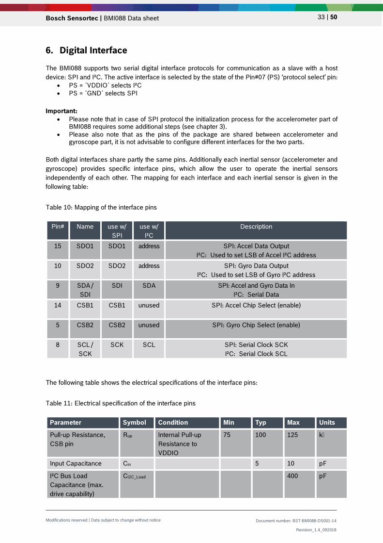
6. Digital Interface
The BMI088 supports two serial digital interface protocols for communication as a slave with a host device: SPI and I²C. The active interface is selected by the state of the Pin#07 (PS) ‘protocol select’ pin:
• PS = ´VDDIO´ selects I²C • PS = ´GND´ selects SPI
Important:
• Please note that in case of SPI protocol the initialization process for the accelerometer part of BMI088 requires some additional steps (see chapter 3).
• Please also note that as the pins of the package are shared between accelerometer and gyroscope part, it is not advisable to configure different interfaces for the two parts.
Both digital interfaces share partly the same pins. Additionally each inertial sensor (accelerometer and gyroscope) provides specific interface pins, which allow the user to operate the inertial sensors independently of each other. The mapping for each interface and each inertial sensor is given in the following table:
Table 10: Mapping of the interface pins
Pin# Name use w/ SPI
use w/ I²C
Description
15 SDO1 SDO1 address SPI: Accel Data Output I²C: Used to set LSB of Accel I²C address
10 SDO2 SDO2 address SPI: Gyro Data Output I²C: Used to set LSB of Gyro I²C address
9 SDA / SDI
SDI SDA SPI: Accel and Gyro Data In I²C: Serial Data
14 CSB1 CSB1 unused SPI: Accel Chip Select (enable)
5 CSB2 CSB2 unused SPI: Gyro Chip Select (enable)
8 SCL / SCK
SCK SCL SPI: Serial Clock SCK I²C: Serial Clock SCL
The following table shows the electrical specifications of the interface pins:
Table 11: Electrical specification of the interface pins
Parameter Symbol Condition Min Typ Max Units
Pull-up Resistance, CSB pin
Rup Internal Pull-up Resistance to VDDIO
75 100 125 k
Input Capacitance Cin 5 10 pF
I²C Bus Load Capacitance (max. drive capability)
CI2C_Load 400 pF

Bosch Sensortec | BMI088 Data sheet 34 | 50
Modifications reserved | Data subject to change without notice Document number: BST-BMI088-DS001-14
Revision_1.4_092018
In order to allow for the correct internal synchronisation of data written to the BMI088, a wait time of at least 2 µs (normal mode) or 1000 µs (suspend mode) must be followed.
6.1 Serial Peripheral Interface (SPI) The behavior of the SPI interface is slightly different between gyroscope part and accelerometer part:
• Initialization phase: as described in chapter 3, the interface of the gyroscope part is selected by the level of the PS pin. In contrast to this, the accelerometer part starts always in I2C mode (regardless of the level of the PS pin) and needs to be changed to SPI mode actively by sending a rising edge on the CSB1 pin (chip select of the accelerometer), on which the accelerometer part switches to SPI mode and stays in this mode until the next power-up-reset. To change the sensor to SPI mode in the initialization phase, the user could perfom a dummy SPI read operation, e.g. of register ACC_CHIP_ID (the obtained value will be invalid).
• In case of read operations, the SPI interface of the accelerometer part does not send the requested information directly after the master has send the corresponding register address, but sends a dummy byte first, whose content is not predictable. Only after this dummy byte the desired content is sent. (This dummy byte procedure does not apply to the gyroscope part.) Please find more details below in section 6.1.2.
The timing specification for SPI of the BMI088 is given in the following table:
Table 12: SPI timing
Parameter Symbol Condition Min Max Units
Clock Frequency fSPI Max. Load on SDI or SDO = 25pF
10 MHz
SCK Low Pulse tSCKL 45 ns SCK High Pulse tSCKH 45 ns SDI Setup Time tSDI_setup 20 ns SDI Hold Time tSDI_hold 20 ns SDO Output Delay tSDO_OD Load = 25pF 30 ns
Load = 250pF, VDDIO > 2.4V
40 ns
CSB Setup Time tCSB_setup 40 ns CSB Hold Time tCSB_hold 40 ns Idle time between write accesses
tIDLE_wacc normal mode 2 µs

Bosch Sensortec | BMI088 Data sheet 35 | 50
Modifications reserved | Data subject to change without notice Document number: BST-BMI088-DS001-14
Revision_1.4_092018
The following figure shows the definition of the SPI timings:
tSDI_hold
tSCKH
tCSB_holdtCSB_setup
tSDI_setup
tSCKL
tSDO_OD
CSB
SCK
SDI
SDO
Figure 2: SPI timing diagram
The SPI interface of the BMI088 is compatible with two modes, ´00´ and ´11´. The automatic selection between [CPOL = ´0´ and CPHA = ´0´] and [CPOL = ´1´ and CPHA = ´1´] is controlled based on the value of SCK after a falling edge of CSB (1 or 2).
6.1.1 SPI interface of gyroscope part For single byte read as well as write operations, 16-bit protocols are used. The SPI interface also supports multiple-byte read operations (burst-read). The communication starts when the CSB (1 or 2) is pulled low by the SPI master and stops when CSB (1 or 2) is pulled high. SCK is also controlled by SPI master. SDI and SDO (1 or 2) are driven at the falling edge of SCK and should be captured at the rising edge of SCK. The data bits are used as follows:
• Bit #0: Read/Write bit. When 0, the data SDI is written into the chip. When 1, the data SDO from the chip is read.
• Bit #1-7: Address AD(6:0). • Bit #8-15: when in write mode, these are the data SDI, which will be written into the
address. When in read mode, these are the data SDO, which are read from the address.
Multiple read operations (burst-read) are possible by keeping CSB low and continuing the data transfer (i.e. continuing to toggle SCK). Only the first register address has to be written. Addresses are automatically incremented after each read access as long as CSB stays active low.
6.1.2 SPI interface of accelerometer part In case of read operations of the accelerometer part, the requested data is not sent immediately, but instead first a dummy byte is sent, and after this dummy byte the actual reqested register content is transmitted.

Bosch Sensortec | BMI088 Data sheet 36 | 50
Modifications reserved | Data subject to change without notice Document number: BST-BMI088-DS001-14
Revision_1.4_092018
This means that – in contrast to the description in section 6.1.1 – a single byte read operation requires to read 2 bytes in burst mode, of which the first received byte can be discarded, while the second byte contains the desired data. The same applies to burst-read operations. For example, to read the accelerometer values in SPI mode, the user has to read 7 bytes, starting from address 0x12 (ACC data). From these bytes the user must discard the first byte and finds the acceleration information in byte #2 – #7 (corresponding to the content of the addresses 0x12 – 0x17). The data bits are used as follows:
• Bit #0: Read/Write bit. When 0, the data SDI is written into the chip. When 1, the data SDO from the chip is read.
• Bit #1-7: Address AD(6:0). • Bit #8-15:
o When in write mode, these are the data SDI, which will be written into the address.
o When in read mode, these bits contain unpredictable values, and the user has to read Bit #16-23 to get the actual data from the reading address.
6.2 Inter-Integrated Circuit (I²C) The I²C bus uses SCL (= SCx pin, serial clock) and SDA (= SDx pin, serial data input and output) signal lines. Both lines are connected to VDDIO externally via pull-up resistors so that they are pulled high when the bus is free. The I²C interface of the BMI088 is compatible with the I²C Specification UM10204 Rev. 03 (19 June 2007), available at http://www.nxp.com. The BMI088 supports I²C standard mode and fast mode, only 7-bit address mode is supported. The default I²C addresses are:
Accelerometer: SDO1 pin pulled to ‘GND’: 0011000b (0x18) SDO1 pin pulled to ‘VDDIO’: 0011001b (0x19)
Gyroscope: SDO2 pin pulled to ‘GND’: 1101000b (0x68) SDO2 pin pulled to ‘VDDIO’: 1101001b (0x69)
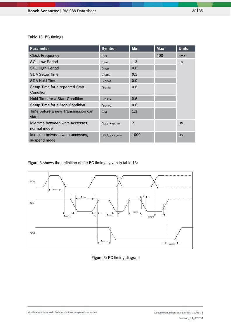
The timing specification for I²C of the BMI088 is given in table 13:
Bosch Sensortec | BMI088 Data sheet 37 | 50
Modifications reserved | Data subject to change without notice Document number: BST-BMI088-DS001-14
Revision_1.4_092018
Table 13: I²C timings
Parameter Symbol Min Max Units
Clock Frequency fSCL 400 kHz SCL Low Period tLOW 1.3 µs SCL High Period tHIGH 0.6 SDA Setup Time tSUDAT 0.1 SDA Hold Time tHDDAT 0.0 Setup Time for a repeated Start Condition
tSUSTA 0.6
Hold Time for a Start Condition tHDSTA 0.6 Setup Time for a Stop Condition tSUSTO 0.6 Time before a new Transmission can start
tBUF 1.3
Idle time between write accesses, normal mode
tIDLE_wacc_nm 2 µs
Idle time between write accesses, suspend mode
tIDLE_wacc_sum 1000 µs
Figure 3 shows the definition of the I²C timings given in table 13:
Figure 3: I²C timing diagram
tHDDAT
tf
tBUF
SDA
SCL
SDA
tLOW
tHDSTA tr
tSUSTA
tHIGH
tSUDAT
tSUSTO

Bosch Sensortec | BMI088 Data sheet 38 | 50
Modifications reserved | Data subject to change without notice Document number: BST-BMI088-DS001-14
Revision_1.4_092018
The I²C protocol works as follows: START: Data transmission on the bus begins with a high to low transition on the SDA line while SCL is held high (start condition (S) indicated by I²C bus master). Once the START signal is transferred by the master, the bus is considered busy. STOP: Each data transfer should be terminated by a Stop signal (P) generated by master. The STOP condition is a low to HIGH transition on SDA line while SCL is held high. ACK: Each byte of data transferred must be acknowledged. It is indicated by an acknowledge bit sent by the receiver. The transmitter must release the SDA line (no pull down) during the acknowledge pulse while the receiver must then pull the SDA line low so that it remains stable low during the high period of the acknowledge clock cycle. In the following diagrams, these abbreviations are used: S Start P Stop ACKS Acknowledge by slave ACKM Acknowledge by master NACKM Not acknowledge by master RW Read / Write A START immediately followed by a STOP (without SCL toggling from ´VDDIO´ to ´GND´) is not supported. If such a combination occurs, the STOP is not recognized by the device. I²C write access: I²C write access can be used to write a data byte in one sequence. The sequence begins with start condition generated by the master, followed by 7 bits slave address and a write bit (RW = 0). The slave sends an acknowledge bit (ACK = 0) and releases the bus. Then the master sends the one byte register address. The slave again acknowledges the transmission and waits for the 8 bits of data, which shall be written to the specified register address. After the slave acknowledges the data byte, the master generates a stop signal and terminates the writing protocol. Example of an I²C write access to the accelerometer, writing 0xA8 to address ox40 (i.e. setting continuous filter function, averaging to 4 samples, ODR to 100Hz):
Figure 4: I²C write
Star
t
RW
ACKS
dum
my
ACKS
ACKS
Stop
S 0 0 1 1 0 0 0 0 A 0 1 0 0 0 0 0 0 A 1 0 1 0 1 0 0 0 A P
Slave address (0x18) Data (0xA8)Register address (0x40)

Bosch Sensortec | BMI088 Data sheet 39 | 50
Modifications reserved | Data subject to change without notice Document number: BST-BMI088-DS001-14
Revision_1.4_092018
I²C read access: I²C read access also can be used to read one or multiple data bytes in one sequence. A read sequence consists of a one-byte I²C write phase followed by the I²C read phase. The two parts of the transmission must be separated by a repeated start condition (Sr). The I²C write phase addresses the slave and sends the register address to be read. After slave acknowledges the transmission, the master generates again a start condition and sends the slave address together with a read bit (RW = 1). Then the master releases the bus and waits for the data bytes to be read out from slave. After each data byte the master has to generate an acknowledge bit (ACK = 0) to enable further data transfer. A NACKM (ACK = 1) from the master stops the data being transferred from the slave. The slave releases the bus so that the master can generate a STOP condition and terminate the transmission. The register address is automatically incremented and, therefore, more than one byte can be sequentially read out. Once a new data read transmission starts, the start address will be set to the register address specified in the latest I²C write command. By default, the start address is set at 0x00. In this way, repetitive multi-bytes reads from the same starting address are possible.

Bosch Sensortec | BMI088 Data sheet 40 | 50
Modifications reserved | Data subject to change without notice Document number: BST-BMI088-DS001-14
Revision_1.4_092018
Example of an I²C read access to the accelerometer, reading all 6 bytes containing acceleration data (0x12-0x17):
Figure 5: I²C multiple read
Sta
rt
RW
AC
KS
dum
my
AC
KS
S 0 0 1 1 0 0 0 0 A x 0 0 1 0 0 1 0 A
Sta
rt
RW
AC
KS
AC
KM
AC
KM
Sr 0 0 1 1 0 0 0 1 A x x x x x x x x A x x x x x x x x A …A
CK
S
AC
KM
AC
KM
… A x x x x x x x x A x x x x x x x x A …
AC
KS
AC
KM
NA
CK
M
Sto
p
… A x x x x x x x x A x x x x x x x x NA P
Slave address (0x18) Register address (0x12)
Slave address (0x18) Read data (0x12) Read data (0x13)
Read data (0x14) Read data (0x15)
Read data (0x16) Read data (0x17)

Bosch Sensortec | BMI088 Data sheet 41 | 50
Modifications reserved | Data subject to change without notice Document number: BST-BMI088-DS001-14
Revision_1.4_092018
7. Pin-out and Connection Diagram
Figure 6: Pin-out top view Figure 7: Pin-out bottom view
7.1 Pin-out
Table 14: Pin description
Pin# Name I/O Type Description SPI mode I2C mode 1* INT2 Digital I/O Interrupt pin 2 (accel int #2) INT2 INT2 2 NC -- -- GND GND 3 VDD Supply Power supply analog & digital
domain (2.4 – 3.6V) VDD VDD
4 GNDA Ground Ground for analog domain GND GND 5 CSB2 Digital in SPI Chip select Gyro CSB2 DNC (float) 6 GNDIO Ground Ground for I/O GND GND 7 PS Digital in Protocol select gyroscope
(GND = SPI, VDDIO = I²C) GND VDDIO
8 SCL / SCK
Digital in SPI: serial clock SCK I²C: serial clock SCL
SCK SCL
9 SDA / SDI
Digital I/O I²C: SDA serial data I/O SPI 4W: SDI serial data I SPI 3W: SDA serial data I/O
SDI SDA
10 SDO2 Digital out SPI Serial data out Gyro Address select in I²C mode see chapter 9.2
SDO2 GND for default addr.
11 VDDIO Supply Digital I/O supply voltage (1.2V … 3.6V)
VDDIO VDDIO
12* INT3 Digital I/O Interrupt pin 3 (gyro int #1) INT3 INT3 13* INT4 Digital I/O Interrupt pin 4 (gyro int #2) INT4 INT4
14 CSB1 Digital in SPI Chip select Accel CSB1 VDDIO or DNC (float)
15 SDO1 Digital out SPI Serial data out Accel Address select in I²C mode see chapter 9.2
SDO1 GND for default addr.
16* INT1 Digital I/O Interrupt pin 1 (accel int #1) INT1 INT1 * If INT are not used, do not connect them (DNC)!
1

Bosch Sensortec | BMI088 Data sheet 42 | 50
Modifications reserved | Data subject to change without notice Document number: BST-BMI088-DS001-14
Revision_1.4_092018
7.2 Connection diagram SPI
Figure 8: SPI connection
7.3 Connection diagram I2C
Figure 9: I2C connection
BMI088

Bosch Sensortec | BMI088 Data sheet 43 | 50
Modifications reserved | Data subject to change without notice Document number: BST-BMI088-DS001-14
Revision_1.4_092018
8. Package
8.1 Outline Dimensions The sensor housing is a standard LGA package. Its dimensions are the following. Unit is mm. Note: Unless otherwise specified tolerance = decimal ± 0.05
Figure 10: Package outline dimensions
Top view
Bottom view

Bosch Sensortec | BMI088 Data sheet 44 | 50
Modifications reserved | Data subject to change without notice Document number: BST-BMI088-DS001-14
Revision_1.4_092018
8.2 Sensing axes orientation If the sensor is accelerated and/or rotated in the indicated directions, the corresponding channels of the device will deliver a positive acceleration and/or yaw rate signal (dynamic acceleration). If the sensor is at rest without any rotation and the force of gravity is acting contrary to the indicated directions, the output of the corresponding acceleration channel will be positive and the corresponding gyroscope channel will be “zero” (static acceleration). Example: If the sensor is at rest or at uniform motion in a gravity field according to the figure given below, the output signals are: • 0g for the X ACC channel and 0°/sec for the ΩX GYR channel • 0g for the Y ACC channel and 0°/sec for the ΩY GYR channel • + 1g for the Z ACC channel and 0°/sec for the ΩZ GYR channel
Figure 11: Orientation of sensing axis
The following table lists all corresponding output signals on X, Y, Z while the sensor is at rest or at uniform motion in a gravity field under assumption of a top down gravity vector as shown above. The gyroscope signals ΩX, ΩY, ΩZ show 0dps output under these static conditions. Table 15: Output signals depending on device orientation
Sensor orientation (gravity vector )
Output Signal X 0g +1g 0g -1g 0g 0g
Output Signal Y -1g 0g +1g 0g 0g 0g
Output Signal Z 0g 0g 0g 0g +1g -1g
upright
upright
o
o
o
o
force of gravity

Bosch Sensortec | BMI088 Data sheet 45 | 50
Modifications reserved | Data subject to change without notice Document number: BST-BMI088-DS001-14
Revision_1.4_092018
8.3 Marking 8.3.1 Mass production samples Table 16: Marking of mass production parts
Labeling Name Symbol Remark
Product number 365 3 numeric digits, fixed to identify product type
Sub-con ID L 1 alphanumeric digit, variable to identify sub-con
Date-Code YYWW 4 numeric digits, fixed to identify YY = “year” WW = “working week
Lot counter CCCC 4 alphanumeric digits, variable to generate mass production trace-code
Pin 1 identifier • --
8.3.2 Engineering samples
Table 17: Marking of engineering samples
Labeling Name Symbol Remark
Eng. sample ID N 1 alphanumeric digit, fixed to identify engineering sample, N = “+” or “e” or “E”
Sample ID PYYWW P: assembly house YYWW: Year (last 2 digits)/Work week
Counter ID CC C-samples; lot number (e.g.C5: C-samples, 5th lot)
Pin 1 identifier • --
8.4 PCB layout and soldering guidelines
The following general layout rules are recommended • PCB land width = LGA solder pin width • PCB land length = LGA solder pin length + 0.1 mm on each side • Solder mask opening width = PCB land width + 0.05 mm on each side • Solder mask opening length = PCB land length + 0.05 mm on each side
Recommendation about stencil design and solder paste application
• It is recommended to keep the openings of the stencil mask for the signal pads between 70% and 90% of the PCB pad area.
• An accurate alignment of the stencil and the printed circuit board (within 0.025mm) is recommended.
• A stencil thickness of 80 – 150 μm is recommended for screen printing
088N PYYWW
CC
365 LYYWW
CCCC

Bosch Sensortec | BMI088 Data sheet 46 | 50
Modifications reserved | Data subject to change without notice Document number: BST-BMI088-DS001-14
Revision_1.4_092018
The moisture sensitivity level (MSL) of the BMI088 sensors corresponds to JEDEC Level 1. See also: • IPC/JEDEC J-STD-020C “Joint Industry Standard: Moisture/Reflow Sensitivity Classification
for non-hermetic Solid State Surface Mount Devices” • IPC/JEDEC J-STD-033A “Joint Industry Standard: Handling, Packing, Shipping and Use of
Moisture/Reflow Sensitive Surface Mount Devices” The sensor fulfils the lead-free soldering requirements of the above-mentioned IPC/JEDEC standard, i.e. reflow soldering with a peak temperature up to 260°C. For more details, refer the Handling, Soldering and Mounting Instructions document available at https://www.bosch-sensortec.com/bst/support_tools/downloads/overview_downloads
8.5 Handling instructions Micromechanical sensors are designed to sense acceleration with high accuracy even at low amplitudes and contain highly sensitive structures inside the sensor element. The MEMS sensor can tolerate mechanical shocks up to several thousand g’s. However, these limits might be exceeded in conditions with extreme shock loads such as e.g. hammer blow on or next to the sensor, dropping of the sensor onto hard surfaces etc. We recommend to avoid g-forces beyond the specified limits during transport, handling and mounting of the sensors in a defined and qualified installation process. This device has built-in protections against high electrostatic discharges or electric fields (e.g. 2kV HBM); however, anti-static precautions should be taken as for any other CMOS component. Unless otherwise specified, proper operation can only occur when all terminal voltages are kept within the supply voltage range. Unused inputs must always be tied to a defined logic voltage level.
8.6 Tape and Reel specification BMI088 is shipped in a standard cardboard box. The box dimension for each reel is L x W x H = 35cm x 35cm x 5cm. Each reel contains 5,000pcs of BMI088.
A0 = 4.85; B0 = 3.35; K0 = 1.20
Tape and reel dimensions in mm

Bosch Sensortec | BMI088 Data sheet 47 | 50
Modifications reserved | Data subject to change without notice Document number: BST-BMI088-DS001-14
Revision_1.4_092018
8.6.1 Orientation within the reel
Orientation of the BMI088 devices relative to the tape
8.7 Environmental safety The BMI088 sensor meets the requirements of the EC restriction of hazardous substances (RoHS) directive, see also:
Directive 2011/65/EU of the European Parliament and of the Council of January 3rd, 2013 on the restriction of the use of certain hazardous substances in electrical and electronic equipment.
8.7.1 Halogen content The BMI088 is halogen-free. For more details on the analysis results please contact your Bosch Sensortec representative.

Bosch Sensortec | BMI088 Data sheet 48 | 50
Modifications reserved | Data subject to change without notice Document number: BST-BMI088-DS001-14
Revision_1.4_092018
9. Legal Disclaimer
9.1 Engineering samples Engineering Samples are marked with an asterisk (*) or (e). Samples may vary from the valid technical specifications of the product series contained in this data sheet. They are therefore not intended or fit for resale to third parties or for use in end products. Their sole purpose is internal client testing. The testing of an engineering sample may in no way replace the testing of a product series. Bosch Sensortec assumes no liability for the use of engineering samples. The Purchaser shall indemnify Bosch Sensortec from all claims arising from the use of engineering samples.
9.2 Product use Bosch Sensortec products are developed for the consumer goods industry. They are not designed or approved for use in military applications, life-support appliances, safety-critical automotive applications and devices or systems where malfunctions of these products can reasonably be expected to result in personal injury. They may only be used within the parameters of this product data sheet. The resale and/or use of products are at the Purchaser’s own risk and the Purchaser’s own responsibility. The Purchaser shall indemnify Bosch Sensortec from all third party claims arising from any product use not covered by the parameters of this product data sheet or not approved by Bosch Sensortec and reimburse Bosch Sensortec for all costs in connection with such claims. The Purchaser accepts the responsibility to monitor the market for the purchased products, particularly with regard to product safety, and inform Bosch Sensortec without delay of any security relevant incidents.
9.3 Application examples and hints With respect to any examples or hints given herein, any typical values stated herein and/or any information regarding the application of the device, Bosch Sensortec hereby disclaims any and all warranties and liabilities of any kind, including without limitation warranties of non-infringement of intellectual property rights or copyrights of any third party. The information given in this document shall in no event be regarded as a guarantee of conditions or characteristics. They are provided for illustrative purposes only and no evaluation regarding infringement of intellectual property rights or copyrights or regarding functionality, performance or error has been made.

Bosch Sensortec | BMI088 Data sheet 49 | 50
Modifications reserved | Data subject to change without notice Document number: BST-BMI088-DS001-14
Revision_1.4_092018
10. Document History and Modification
Rev. No Chapter Description of modification/changes Date 1.0 - Initial release 03-Dec-2017 1.1 All Typos 30-Jan-2018
1.2
3 + 4.1.1 5.2 5.3.6 5.2+5.3.10+5.3.11 5.4
Updated switching between power modes Fixed typo in register range Added clearing condition of data ready int bit Corrected INT pin settings bits Fixed typo in bit naming in register 0x16
23-Mar-2018
1.3 7.1 Updated pin 14 assignment in I2C mode 27-Apr-2018
1.4
4.4.1 + 5.2 + 5.3.8 4.9 5.3.4 7.2 + 7.3 7.2 8.3 8.6
Clarified how to set Accel bandwidth setting Included info on FIFO Corrected conversion from LSB to mg Updated pin 4 and 6 assignment in SPI/I2C mode Clarified connection to SPI host interface Updated marking Included tape & reel specifications
16-Sep-2018

Bosch Sensortec | BMI088 Data sheet 50 | 50
Modifications reserved | Data subject to change without notice Document number: BST-BMI088-DS001-14
Revision_1.4_092018
Bosch Sensortec GmbH Gerhard-Kindler-Straße 9 72770 Reutlingen / Germany [email protected] www.bosch-sensortec.com Modifications reserved Preliminary - specifications subject to change without notice Document number: BST-BMI088-DS001-14 Revision_1.4_092018

Mouser Electronics
Authorized Distributor
Click to View Pricing, Inventory, Delivery & Lifecycle Information: Bosch:
BMI088