Bearings - MTO & Co. AG · Minebea Co., Ltd., was established in 1951 as Japan’s first...
64
Miniature Precision Ball Bearings Bearings
Transcript of Bearings - MTO & Co. AG · Minebea Co., Ltd., was established in 1951 as Japan’s first...

Miniature Precision Ball Bearings
Bearings

NMB Technologies Corporation is a subsidiary of NMB (USA) Inc., the North American headquarters and operating center of the Minebea Group of Companies.
Minebea Co., Ltd., was established in 1951 as Japan’s first specialized manufacturer of miniature ball bearings. Today, the Company is the world’s leading comprehensive manufacturer of miniature ball bearings and high precision components, supplying customers worldwide in the
information and telecommunications equipment industry, as well as automotive, medical, aerospace, industrial and household electrical appliance industry. The Minebea Group consists of 49 subsidiaries and affiliates in 14 countries, including Japan, Thailand, Cambodia, Singapore and China, as well as several others in Europe and the Americas. The Group main-tains 29 plants, R&D facilities and 44 sales offices, and employs over 54,000 people worldwide.
NMB’s miniature and small ball bearings are manufac-tured in Thailand and Singapore, and range in size from .1181 to 1.000 inch, outside diameter, providing high performance within a small envelope design.
NMB Technologies Corporation’s domestic headquarters are located in Chatsworth, California. Highly trained application engineers, experienced product managers and customer service representatives work closely with customers to develop the most cost effective solution for today’s challenging applications. Pre-design and after-delivery follow up assure complete customer satisfaction. Contact NMB Technologies Corporation today. Visit our web site at www.nmbtc.com or call our Bearing Support Group directly at 818-341-3355.
NMB Technologies Corporation

Section 1 Introduction ..................................................................................................................................................4 - 11
Section 2Bearing Engineering .................................................................................................................................. 12 - 43
Section 3Metric Series Bearings .............................................................................................................................. 44 - 53
Section 4Inch Series Bearings .................................................................................................................................. 54 - 57
Section 5Bearing Damage & Countermeasure ..................................................................................................... 58 - 59
Section 6 Appendix .................................................................................................................................................... 60 - 62
Table of Contents

NMBTC.COM / 818.341.3355NMBTC.COM / 818.341.3355
Section 1
Quality Assurance System
Minebea produces the same level of high quality products at all of our factories located world wide. All of the product departments have acquired and maintained registration to ISO9000 and ISO/TS16949 international standards of quality. At major produc-tion sites in Thailand, Singapore, and China, R&D centers have been founded for the purpose of per-forming various analyses, and improving quality levels at each production site.
Environmental Activities
A most important theme upheld by the whole Minebea group is environmental protection. Since 1993, environmental protection activities have been accomplished with “environment vision” being estab-lished as a fundamental policy. The Minebea group has acquired registration to international environ-mental management standard ISO14001. From the design development phase to the production and shipment phase, Minebea makes every effort to pro-duce products which meet goals such as “No harmful substances for environment, health, and safety,” “less energy consumption,” and “3R reduced, reused, and recycled.”
Minebea does not just follow every environmental regulation. We also protect the environments of the communities where our offices are located. In addi-tion to regular environmental checkups at each fac-tory and office, employees are educated to maintain clean environments at both their workplace and home.
Warnings and PrecautionsBall bearings are precise components that require careful handling. Without understanding the per-formance and application conditions of the ball bearing, optimum performance can not be achieved. Improper usage could lead to malfunctioning and/or failure. Please adhere to the warnings that follow.
Warnings
• NMB is not responsible for damage to products caused by installed ball bearings that were used in unforeseeable ways.
• NMB is not responsible for damage to ball bearings and/or products caused by installed ball bearings if modified in any way.
• NMB is not responsible for any damage caused by installed ball bearings if the application conditions and/or equipment specifications are changed after determining the specification.
• The products described in this catalog are not meant to be used for nuclear power related equipment. NMB is not responsible for damage to products caused by ball bearings if used for nuclear power related applications.
Precautions
Selecting a Ball Bearing
Please contact NMB if any of the conditions described below apply to your application.
• If ball bearings are used under extreme condi-tions (i.e. high speed, high and/or low tempera-tures, high and low humidity, and high loads).
• If the application requires high precision.
• If ball bearings are utilized as the critical security parts of the following applications: aircraft, aerospace related equipment, public services (i.e. electricity and gas), automotive, shipping equipment, parking structure devices, elevating devices, medical equipment, and toys.
• If mating parts contain plastics, these may be degraded and/or damaged from interaction with certain oils and/or greases.
• If electrical current passes through ball bearings.
• If the ball bearing is used in a potentially cor-rosive environment (i.e. exposure to gas, vapor, and/or liquid).
Intr
oduc
tion
4
Activities of Minebea

NMBTC.COM / 818.341.3355NMBTC.COM / 818.341.3355
Introduction
5
Storing Ball Bearings
To avoid potential issues with ball bearings during storage (i.e. contamination, rust, and/or grease degradation), please adhere to the following directions:
• Avoid high temperature and high humidity environments.
• Avoid placing the product packages directly on the floor and utilize pallets during storage.
• Unpack the product package in clean areas and do not leave the ball bearings unprotected.
• Avoid contact with dirty cloths, which could possibly transfer contamination particles.
• Avoid handling the ball bearings with bare hands.
• Avoid placing ball bearings in corrosive conditions (gas, vapor, and liquid).
• Avoid placing ball bearings near magnets or magnetized metals.
During Installation into Equipment
Careful handling is required during bearing installation. Impacts and high loads can produce dents and damage within the bearings that will degrade performance and reduce bearing life.
• Please do not drop the ball bearings.
• Please do not use tools like hammers which can produce impact loads.
• Excessive loads must not be applied.
• Please keep the installation environment clean.
• Please use designated installation tools and fixtures, and keep them clean.
• Please keep the parts near shafts or housings clean.
• Please do not touch the bearings directly with bare hands. Use dust free gloves or finger cots.
Storing and Shipping of Equipment
If vibration is applied to equipment using ball bearings, fretting could occur inside the ball bearings. This eventually causes bearing noise and early end of life. If impact loads are applied, damage and dents gener-ated inside the bearing could cause degradation and early end of life.
• Equipment assembled with ball bearings should be packed by shock absorbing methods to avoid damage from impact loads. If the equipment has rotational parts like impellers, they should not be allowed to rotate inside the packing boxes.
• During shipping, no vibration or shock should be applied to the equipment.
Operation Test of Ball Bearings
• After installing ball bearings, we recommend performing an operation test to confirm no abnormal phenomena have occurred. During the test, the rotation speed should be raised gradually.
• If any abnormalities are found, the operation test should be terminated and the source should be investigated. Please do not use bearings if they are suspect or damaged.
Other
• Please confirm the types of lubricants at the time of purchase. Some sealed and shielded bearings in the market use only oil lubrication.
• In “the foreign exchange and foreign trade law,” some ball bearing components are considered as foreign goods under export control. Export approval from the Japanese minister of economy is required to export the foreign goods defined in the law.
Section 1

NMBTC.COM / 818.341.3355NMBTC.COM / 818.341.3355
Section 1
Minebea’s main ball bearing product is the single row radial deep groove ball bearing. Deep groove radial ball bearings with shields or seals are available to provide protection from contamination and grease leakage. Flange type and snap ring type bearings are available for improved housing fits. NMB also produces ultra thin type radial ball bearings, thrust ball bearings, and bearings.
Intr
oduc
tion
6
Radial Deep Groove Ball Bearings (R-, L-, RI-)
Characteristics:This is the most common type of radial ball bearing. This type of ball bearing can support both radial and axial loads.
Types:Open, shielded, and sealedMetric and Inch series
Flanged Radial Deep Groove Ball Bearings (RF-, LF-, RIF-)
Characteristics:This is a radial ball bearing with a flange featured on one side of the outer ring surface. It assists with axial positioning of the bearing in a housing.
Types:Open, shielded, and sealedMetric and Inch series
Radial Deep Groove Ball Bearings with Outer Snap Ring (RNR-, LNR-)
Characteristics:This is a radial ball bearing with an external retaining ring featured on one side of the outer ring surface. This design assists with axial positioning of the bearing in a housing.
Types:Open and shielded*High carbon chromium steel is the standard material
Ultra Thin Radial Ball Bearings (A-)
Characteristics:The bore relative to the outer diameter is larger than those of standard radial ball bearings.
Types:Open and shielded*Stainless steel is the standard material
Bearing Types

NMBTC.COM / 818.341.3355NMBTC.COM / 818.341.3355
Introduction
7
Section 1
Bearing Types (continued)
Thrust Ball Bearings (T-)
Characteristics:A thrust ball bearing bears axial loads, but not radial loads.
Types:With or without raceway grooves.*Stainless Steel is the standard material.

NMBTC.COM / 818.341.3355NMBTC.COM / 818.341.3355
Section 1
Names and SymbolsA ball bearing is composed of an outer and inner ring, balls and a retainer. It is also available with shields, seals, flanges, and snap rings.
Intr
oduc
tion
8
Outer Ring
Inner Ring Chamfer
Inner Ring
Outer Ring Chamfer
Ball
Retainer
Width (B)
Width (B)
Snap RingShield
Flange Width (C1)
ExternalRetaining Ring
ExternalRetaining RingPosition (C2)
Bor
e (d
)B
ore
(d)
Inne
r Rin
gSh
ould
er D
iam
eter
(Li)
Out
er R
ing
Shou
lder
Dia
met
er (L
o)
Inne
r Rin
gSh
ould
er D
iam
eter
(Li)
Out
er R
ing
Shou
lder
Dia
met
er (L
o)
Out
er D
iam
eter
(D)
Out
er D
iam
eter
(D)
Flan
ge O
uter
Dia
met
er (D
1)
Exte
rnal
Ret
aini
ng R
ing
Out
er D
iam
eter
(D2)
Standard Shield Type
External Retaining Ring TypeFlange Type
Ball Bearing Components

NMBTC.COM / 818.341.3355NMBTC.COM / 818.341.3355
IntroductionSection 1
NMB Part Number
Part Numbering SystemThe NMB Part Numbering System is comprised of the base part number and specification. The NMB Part Numbering system is unique to Minebea. JIS Part Numbering is based on a system that is defined in the JIS 1513 standard.
Base Part NumberRing & Ball Material Series Size
Details: Page 15 - -DD R- 1560
Base Part NumberEnclosure Noise Grade/Special Feature Retainer
Details: Page 16 - Details: Page 17ZZ MT R
No Code SAE52100 or Equivalent Bearing SteelDD Martensitic Stainless SteelCE Outer/Inner Ring: SAE52100 or Equivalent Bearing Steel Ball: Ceramic
Metric Radial Ball Bearing:R-(RF-) R-Series (Flanged)
L-(LF-) L-Series (Flanged)
A- Ultra Thin Type
RNR- R-Series with External Retaining Ring
LNR- L-Series with External Retaining RingInch Radial Ball Bearing:
RI- Inch Type
(R-) Used for particular Inch Types
RIF- Inch Flanged TypeThrust Ball Bearing:T-
Special Type:ZB- Integrated Shaft BearingAS- Special Type
Derived from the outside and bore diameters.
Ex: Metric Size1560 OD 15mm Bore 6mm
Ex: Inch Size418 OD 4/16 inch Bore 1/8 inch
X If the bearing design is different from basic, this comes after basic symbols.
Ex: 1560X2OD = 15 mmBore = 6 mmInternal Design = X2 Type
No Code OpenZ Metallic Shield (Fitted with Snap-Ring)H Metallic Shield (Pressed)K Metallic Shield (Staked)D Rubber Seal (Contact)S Rubber Seal (Non-Contact)
Note: Double symbol indicates enclo-sures on both sides (e.g. ZZ, DD).
No Code StandardMT Electric motor quality (For extremely noise sensitive applications)
SD Special DesignW Wider width than standardY Narrower width than standardEE Extended Inner Ring
R Ribbon Retainer (Steel)H Crown Retainer (Steel)MN Plastic Retainer (Glass Fiber reinforced)
Note: Other materials are also available for the plastic retainer.
9

NMBTC.COM / 818.341.3355
Section 1
NMB Part Number (Example #1)
R Series Outer Diameter: 8mmBore Diameter: 3mmInternal Design: X10 TypeMetallic ShieldsSpecial Design Specification
NMB Part Number (Example #2)
Material: Stainless SteelL SeriesOuter Diameter: 16mmBore Diameter: 8mmRubber Seals (Contact)
Lubricant: LY551 (Grease) Radial Play: 12.5µm ~ 20.0µm ABEC Grade 5 Plastic Retainer
R - 8 3 0 X10 ZZ S D1 0 MTR A 5 P 2 4 L O 1
DDL - 1 6 8 0DDMN A 5 P 5 8 L Y 5 5 I
Intr
oduc
tion
10
Bearing SpecificationABEC Grade Radial Play Lubricant Grease Fill Amount
Details: Page 21 Details: Page 28 Details: Page 40 Details: Page 40A1 P25 LY121 L
A1 ABEC grade 1A3 ABEC grade 3A5 ABEC grade 5A7 ABEC grade 7
P13 .0001”~.0003” (2.5µm~ 7.5µm)
P24 .0002”~.0004” (5.0µm~ 10.0µm)
P25 .0002”~.0005” (5.0µm~ 12.5µm)
P58 .0005”~.0008” (12.5µm~ 20.5µm)
Note: Letter “P” followed by two to four numbers indicates the radial play range in ten thousandths of an inch.
Ex: P25 indicates radial play of .0002” to .0005” (5.0µm to 12.5µm).
LO OilLG GreaseLY Grease or OilLD No Lubrication
No Code Standard (25% ~ 35%)
X 5% ~ 10%
L 10% ~ 15%
T 15% ~ 20%
H 40% ~ 50%
J 50% ~ 60%Note 1: Precentage of the void space within the assembled bearing that is filled with grease.
Note 2: Some miniature ball bearings need amount adjustment.
NMB Part Number (continued)
Lubricant: LO1 (Oil)Radial Play: 5.0µm - ~ 10.0 µm
ABEC Grade 5Ribbon Retainer
Electric Motor Quality
1.5
NMBTC.COM / 818.341.3355NMBTC.COM / 818.341.3355
Section 1
JIS Part Number
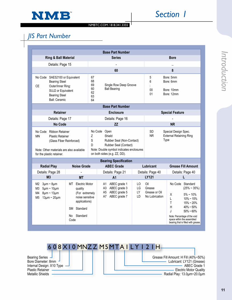
Bearing Series Bore Diameter: 8mmInternal Design: X10 TypePlastic RetainerMetallic Shields
Grease Fill Amount: H Fill (40%~50%)Lubricant: LY121 (Grease)
ABEC Grade 1Electric Motor Quality
Radial Play: 13.0µm~20.0µm
Introduction
11
Base Part NumberRing & Ball Material Series Bore
Details: Page 15 - _
60 8
Base Part NumberRetainer Enclosure Special Feature
Details: Page 17 Details: Page 16 -No Code ZZ NR
Bearing SpecificationRadial Play Noise Grade ABEC Grade Lubricant Grease Fill Amount
Details: Page 28 - Details: Page 21 Details: Page 40 Details: Page 40M3 MT A1 LY121 L
No Code SAE52100 or Equivalent Bearing SteelCE Outer/Inner Ring: SUJ2 or Equivalent Bearing Steel Ball: Ceramic
67 68 69 Single Row Deep Groove 60 Ball Bearing62 6364
5 Bore: 5mm6 Bore: 6mm:00 Bore: 10mm01 Bore: 12mm
No Code Ribbon RetainerMN Plastic Retainer (Glass Fiber Reinforced)
Note: Other materials are also available for the plastic retainer.
No Code Open Z Shield S Rubber Seal (Non-Contact) D Rubber Seal (Contact)Note: Double symbol indicates enclosures on both sides (e.g. ZZ, DD).
SD Special Design Spec.NR External Retaining Ring Type
M2 3µm ~ 8µmM3 5µm ~ 10µmM4 8µm ~ 13µmM5 13µm ~ 20µm
LO OilLG GreaseLY Grease or OilLD No Lubrication
MT Electric Motor quality (For extremely noise sensitive applications)
SM Standard
No Standard Code
A1 ABEC grade 1A3 ABEC grade 3A5 ABEC grade 5A7 ABEC grade 7
No Code Standard (25% ~ 35%)
X 5% ~ 10%L 10% ~ 15%T 15% ~ 20%H 40% ~ 50%J 50% ~ 60%
Note: Percentage of the void space within the assembled bearing that is filled with grease.
6 0 8 X1 0 MNZ Z M5MTA I L Y 1 2 1 H

2.2
NMBTC.COM / 818.341.3355
Section 2Be
arin
g En
gine
erin
g
12
To select a ball bearing part number and specification properly, it is necessary to fully understand the required performance of the ball bearing by confirming the structures, dimensions, environment, and conditions of each application using the ball bearing. The process of selecting a ball bearing is shown below.
Application Conditions, Environment, Required Performance Application Structure and Functions .............. Page 14 Application Conditions (Temperature, Humidity, Vibration, Dust, etc.) Loads Dimension and Material of Shaft and Housing Speed, Rotation Precision, Rotating Ring Torque Noise Life Regulated Substance(s)
Selecting Part Number Bearing Material ........................... Page 15 Enclosure ...................................... Page 16 Retainer ........................................ Page 17 Load Rating and Life ................. Page 18
Tolerance and Grades Tolerance ..................................... Page 21 Measurement Methods ............ Page 26
Determining Performance Level Internal Clearance ...................... Page 28 Fits .................................................. Page 29 Design of Shaft and Housing .... Page 32 Preload (Preload and Stiffness) ... Page 34 Displacement ............................... Page 35
Selecting Lubricant .......... Page 40-41
Handling .................................. Page 42
Ball Bearing Selection Process
Torque ........................................ Page 36 Vibration by Forced Rotation ... Page 37 Noise .......................................... Page 38 Plastics Compatibility .............. Page 39
Application Conditions, Environment,
Required Performance
Selecting Part Number
Tolerance and Grades
Determining Performance Level
Selecting Lubricant
Handling

NMBTC.COM / 818.341.3355NMBTC.COM / 818.341.3355
Bearing Engineering
F1aFaF2a
F1r F2r
Fi Fr
ca b
13
F1aFaF2a
F1r F2r
Fi Fr
ca b
Section 2
Selecting the Proper BearingThe following work sheet will prove to be very valuable in assisting you in the selection of the correct ball bearing for your application.
Application ConditionsLoads: Fr N F1r N Fa N F1a N Fi N F2r N a mm F2a N b mm c mm
Load Type: Fitting - Shaft: Fitting - Housing Continuous: Diameter: Diameter: Shock: Tolerance: Tolerance: Preload Force: N Material: Material: Applied to: Inner Ring Roundness: Roundness: Outer Ring Surface Finish: Ra µm Surface Finish: Ra µm
Rotation: Speed in RPM: Reverse: Other Rotational Details: Inner Ring Rotation: Oscillating: Outer Ring Rotation: Oscillating Angle: Continuous:
Environment: AmbientTemp.Range: C˚toC˚ Dust: Autoclave: WorkingTemp: C˚ Humidity: OtherDetails: ShaftTemp: C˚ Water: HousingTemp: C˚ Chemicals:
Torque: Torque Sensitive: Yes No Max Torque Increase Allowed: N-mm Output Torque of Motor: N-mm Misalignment: Shaft Alignment Tolerance: mm Bearing Concentricity: mm
Test Plan: Type of Test (life, salt spray, etc.): Run time of test: hours. Duration of test: weeks. Additional Details:
Other Information: Plastic Compatibility Concerns: Yes No Type of Plastic: LifeExpectancy: Hours Current Supplier: Current Part Number: Issues with Current Bearing:
Additional Application Details:

2.2
NMBTC.COM / 818.341.3355
Section 2Be
arin
g En
gine
erin
g
14
The structure of the application, dimensions of the equipment or component which the bearing will be assembled to, and the application environment and conditions need to be confirmed. It is necessary to take several factors into account in order to decide the bearing part number and specification. It is also important to take market factors into account for selecting the bearing part number and specification.
Structure & Function of the EquipmentThe required dimensions and performance need to be based on an understanding of the structure and function of the equipment. Structure limitations are becoming more severe due to downsizing of applications. We recommend taking into account the items listed below and selecting properly to achieve the required bearing performance.
Application Environment
The bearing material, retainer and lubricants are selected based on the ranges of predicted tempera-ture and humidity. The proper preload and lubricant are selected based on the vibration conditions. The presence of dust influences the selection of the shield or seal type. Depending on the operation conditions, bearing temperature is occasionally higher than envi-ronmental temperature.
LoadsThe bearing dimension (Part Number) is selected based on the magnitude, position, and direction of loads applied to the bearing. It is necessary to review the structure of the equipment to determine if excessive loads would be applied to the bearing. If so, select a larger size bearing or decrease the loads.
Material and Dimensions of the Shaft and HousingThe dimensions and tolerances of the bore diameter, outer diameter, and width are selected based on the dimensions and material of the shaft and housing.
Temperature changes can affect the bearing internal clearance if there are differences in linear expansion coefficients of the shaft, housing, and bearing materials.
Speed, Rotation Precision, Rotation RingDimensional tolerance, retainer, clearance, preload, and lubricant are selected based on speed, rotation preci-sion, and rotation conditions (continuous/intermittent/back and forth/outer or inner ring rotation).
TorqueTorque can be classified into either starting torque or running torque. When an application is torque sensitive, enclosure types, lubricant types, fill amount, and retainer types need to be considered carefully.
NoiseWhen an application is noise sensitive, it is necessary to take bearing noise characteristics, lubricants, and preloads into account. Care must be taken during installation and handling. Improper installation, handling damage, or contamination could worsen the noise level.
LifeAlthough rating life is defined in JIS B 1518, life can be defined in various ways because it is affected by the application and the progress of degradation for the required performance level (noise, torque, runout, etc.) for each customer. The various types of life include rating life, noise life, performance life, and lubricant life.
Regulated Substance(s)In recent years, various regulations have been estab-lished for environment, health and safety. It is necessary to confirm if regulated substances listed in the laws are present or not. Substances harmful to the environment and humans are restricted.
Application Conditions, Environment, Required Performance

1.5
NMBTC.COM / 818.341.3355NMBTC.COM / 818.341.3355
Ball bearing performance is significantly influenced by the selection of the proper material for components such as balls, inner and outer rings.
Bearings are exposed to severe stress. The contact area of the outer and inner rings, as well as the balls, are repeatedly exposed to stress exceeding 1,000 MPa. Material type, purity, and hardness are very important factors for long bearing life under repeated high stresses.
High carbon chromium bearing steel and high corrosion-resistant martensitic stainless steels are used for raceway rings and balls in our products.
High carbon chromium bearing steel rings and balls are made from high quality vacuum outgassed steel (JIS G 4805, SUJ2, AISI/SAE52100 or equivalent material). With proper heat treatment, they have high load capacity, longer life and low noise levels.
Minebea developed stainless steel “DD400.” The hardness of DD400 after heat treatment is higher than that of SUS440C. The DD400 material also shows longer life, and high load capacity.
The noise level of DD400 material is close to that of chromium steel because the carbon is dispersed spherically. From results of tests based on ASTM-A380, the corrosion resistance of DD400 material is equal to SUS440C.
To meet longer life and low noise level requirements, ball bearings with ceramic balls are also available. When compared to the conventional chromium bearing steel balls, improved noise level and life can be achieved by using ceramic balls (Silicon Nitride) with the use of conventional chromium rings. The extremely low conductive characteristics (insulation properties) of silicon nitride protect bearings from electric corrosion, which is generated under a conductive environment. In addition, torque reduction can be expected because the ceramic has less mass than bearing steel.
Chromium Bearing Steel
Stainless Steel
Section 2
15
Bearing Engineering
Chemical Composition of Materials
Spec Symbol Chemical Composition (wt%)C Si Mn P S Cr Mo
- DD400 0.60 ~ 0.75 1.00 MAX 1.00 MAX 0.03 MAX 0.02 MAX 11.50 ~ 13.50 0.30 MAX
Spec Symbol Chemical Composition (wt%)C Si Mn P S Cr Mo
JIS G 4805 SUJ2 0.95 ~ 1.10 0.15 ~ 0.35 0.50 MAX 0.025 MAX 0.025 MAX 1.30 ~ 1.60 -
AISI/SAE E52100 0.98 ~ 1.10 0.15 ~ 0.35 0.25 ~ 0.45 0.025 MAX 0.025 MAX 1.30 ~ 1.60 -
Application Conditions, Environment, Required Performance Material

2.2
NMBTC.COM / 818.341.3355
Section 2Be
arin
g En
gine
erin
g
16
Compared to the open type, the shielded and sealed bearing types provide better protection from contamination and grease leakage. They are selected based on the application type and environment.
Shield and Seal
Shield (Snap Ring Type)
NMB part number symbol: ZZ
• Components are shield and snap ring.
• The shield is secured in the outer ring with a snap ring.
• No contact between shield bore and circumfer-ence of inner ring land.
Shield
NMB part number symbol: KK or HHJIS part number symbol: ZZ
• The shield is secured directly in the outer ring.
• No contact between shield bore and circumfer-ence of outer ring land.
Rubber Seal
Common symbol: SS and DD
• Rubber seal with steel insert is secured directly in the outer ring.
• Seals contact circumference of inner ring in DD type, and do not contact in SS type.
• DD is highly sealed, but torque to rotate is higher than non-contact enclosures.
鋼板シールド(スナップリング固定)
鋼板シールド
ゴムシール
鋼板をインサート成形したゴム製シールを直接外輪に固定する構造。 シールと内輪外周が接触しないSSタイプ、接触するDDタイプがある。 DDは密閉性を有するが、トルクが大きくなる。
鋼板シールドとスナップリングで構成される。 鋼板シールドを、スナップリングを用いて外輪に固定する構造。 シールド内径と、内輪外周は接触していない。
NMB呼び型式記号 : ZZ
NMB呼び型式記号 : KK または HH JIS呼び型式記号 : ZZ
共通記号 : SS および DD
鋼板シールドを直接外輪に固定する構造。 シールド内径と、内輪外周は接触していない。
DDSS
④ シールド・シール
シールド付、シール付は、開放形に比べて軸受内への異物侵入やグリースの漏れ出しを抑制することが出来ます。 使用用途や使用環境により選択します。
波形保持器(リボンリテーナ)
冠形保持器(クラウンリテーナ)
樹脂保持器(樹脂リテーナ)
鋼板をプレス成形した2つの部品から構成される。 組立て時には玉を2つの部品で挟み込むように配置し、片方の部品に設けられた爪をもう一方の部品に、かしめて固定する。 一般的な方式で、多く用いられる。
鋼板をプレス成形した1つの部品から構成される。 保持器自体の内径・外径の差を小さく作ることができ、肉薄 タイプや極小径の転がり玉軸受に使用される。
樹脂の成形品や切削品で、1つの部品から構成される。 樹脂は、ポリアミド系、ポリアセタール等がある。 高速回転、低騒音の用途に使用される。
⑤ 保持器(リテーナ)
保持器(リテーナ)は、転がり玉軸受内の玉を等間隔に保つ役割を果たしています。 型式ごとに、標準タイプの保持器を設定していますが、要求性能に合わせて選択する場合もあります。
18 19
1-4 軸受 の選定

1.5
NMBTC.COM / 818.341.3355NMBTC.COM / 818.341.3355
Retainer
Ribbon Retainer
Composed of two stamped steel parts. The balls are held between the two steel parts and the tabs of one of the steel parts are bent over the second steel part to fasten them together. This is the most common type.
Crown Retainer
Composed of a stamped steel part. The small difference in inner and outer diameters of the retainer allows them to be used for thin type and very small ball bearings.
Plastic Retainer
Composed of molded or machined plastic, including Polyamide, Polyacetal and others. It is used for high speed rotation and low noise level.
Section 2
17
Bearing Engineering
Retainers keep the balls separated and equally spaced. Retainer types are set based on the bearing size but can be selected based on the required performance.
鋼板シールド(スナップリング固定)
鋼板シールド
ゴムシール
鋼板をインサート成形したゴム製シールを直接外輪に固定する構造。 シールと内輪外周が接触しないSSタイプ、接触するDDタイプがある。 DDは密閉性を有するが、トルクが大きくなる。
鋼板シールドとスナップリングで構成される。 鋼板シールドを、スナップリングを用いて外輪に固定する構造。 シールド内径と、内輪外周は接触していない。
NMB呼び型式記号 : ZZ
NMB呼び型式記号 : KK または HH JIS呼び型式記号 : ZZ
共通記号 : SS および DD
鋼板シールドを直接外輪に固定する構造。 シールド内径と、内輪外周は接触していない。
DDSS
④ シールド・シール
シールド付、シール付は、開放形に比べて軸受内への異物侵入やグリースの漏れ出しを抑制することが出来ます。 使用用途や使用環境により選択します。
波形保持器(リボンリテーナ)
冠形保持器(クラウンリテーナ)
樹脂保持器(樹脂リテーナ)
鋼板をプレス成形した2つの部品から構成される。 組立て時には玉を2つの部品で挟み込むように配置し、片方の部品に設けられた爪をもう一方の部品に、かしめて固定する。 一般的な方式で、多く用いられる。
鋼板をプレス成形した1つの部品から構成される。 保持器自体の内径・外径の差を小さく作ることができ、肉薄 タイプや極小径の転がり玉軸受に使用される。
樹脂の成形品や切削品で、1つの部品から構成される。 樹脂は、ポリアミド系、ポリアセタール等がある。 高速回転、低騒音の用途に使用される。
⑤ 保持器(リテーナ)
保持器(リテーナ)は、転がり玉軸受内の玉を等間隔に保つ役割を果たしています。 型式ごとに、標準タイプの保持器を設定していますが、要求性能に合わせて選択する場合もあります。
18 19
1-4 軸受 の選定

2.2
NMBTC.COM / 818.341.3355
Section 2Be
arin
g En
gine
erin
g
18
In general, if bearings are made of high quality steel with high level production skills, the load rating and rating life can be calculated based on the specification defined in JIS and ISO.
Life of a Ball BearingThe required life of a ball bearing depends on the application and requirements of the equipment. Because there are many different applications for the equipment, definitions of life also vary. Therefore, life needs to be defined based on the application and requirements.
There are different types of life definitions: rating life, noise life, lubricant life, and performance life. The noise life is considered when bearings become noisier than the originally set level. The lubricant life is considered as when lubricants lose their function due to degradation. The performance life is consid-ered when speed and runout go beyond the accept-able limits and no longer meets the application requirements.
In this section, the rating life of single row deep groove ball bearings, which is specified in JIS B 1518, is explained. Rating life is a predicted life calculated based on the basic dynamic radial load rating.
Basic Rating Life (L10)Defined as the life associated with 90 percent reliability.
According to ABMA Std. 9, for an individual bearing, or a group of apparently identical bearings operating under the same conditions, the life associated with 90% reliability, with contemporary, commonly used material and manufacturing quality, and under conven-tional operating conditions.
The calculation is based on JIS B 1518
L10: Basic rating life (106 revolutions)Cr: Basic dynamic radial load rating (N)Pr: Dynamic equivalent radial load (N)
If the speed is constant, the life is usually expressed in hours. The relationship between basic rating life and life hours is as follows:
L10: Hours (h)n: Speed (rpm)
Basic Dynamic Radial Load Rating (Cr)Defined as the calculated, constant radial load that a group of apparently identical bearings will theoreti-cally endure for a rating life of one million revolutions. The calculation is explained in JIS B 1518. The Basic Dynamic Radial Load Ratings are for reference only.
Dynamic Equivalent Radial Load (Pr)Bearings subjected to primarily dynamic radial loads are often also subject to some axial force. To interpret this combined radial and axial load it is convenient to consider a hypothetical load with a constant magnitude passing through the center of the bearing. This hypo-thetical load is referred to as the Dynamic Equivalent Radial Load and is calculated with the following equation.
Pr = XFr + YFa
X, Y: These values can be found in the table that follows.
Fr: Radial Load (N)Fa: Axial Load (N)
( )L10 =Cr 3
Pr
( )L10 = x 106
60n ( )Cr 3
Pr
Load Rating and Rating Life

2.1
NMBTC.COM / 818.341.3355NMBTC.COM / 818.341.3355
19
1. Calculate Relative Axial Load
2. Calculate e Value to the Relative Axial Load
3. Calculate the Ratio of Radial and Axial Loads
4. Compare the Load Ratio and e Value
5. Determine X and Y
6. Calculate Dynamic Equivalent Load
Pr = 0.56 x 6 + 1.84 x 8 = 18.08
7. Calculate Life Hours
The basic static radial load rating and static equivalent radial load of a
ball bearing are specified in JIS B 1519, “calculation method of static load
rating of a ball bearing.”
Bearing EngineeringSection 2
Fa
ZDw2
8 6 (1.58752)
= = 0.529
(0.529 - 0.345) (0.689 - 0.345)
e = 0.22 + x (0.26 - 0.22) = 0.24
Fa 8
Fr 6= = 1.33
Relative Axial Load Fa/Fr ≤ e Fa/Fr > e Fa Z*Dw
2 e X Y X Y (N) 0.172 0.19 2.30 0.345 0.22 1.99 0.689 0.26 1.71 1.03 0.28 1.55 1.38 0.30 1 0 0.56 1.45 2.07 0.34 1.31 3.45 0.38 1.15 5.17 0.42 1.04 6.89 0.44 1.00
Z: Number of ballsDw: Diameter of ball (mm)*X, Y, e values which are not in the above table can be determined by linear interpolation.*The number of rows for calculating the axial load ratio (specified in JIS) is excluded from the table because it is for a single row bearing.
Calculation ExampleUnder the conditions below, the L10 life of an R-830ZZ bearing is calculated.
Basic Dynamic Radial Load Rating (Cr): 553NBall Diameter (Dw): 1.5875mm Number of Balls: (Z): 6Speed in rpm (n): 3600 min-1
Radial Load (Fr): 6NAxial Load (Fa): 8N
Fa
Fr = 1.33, e = 0.24 > e
Fa
Fr. ..
(0.529 - 0.345) (0.689 - 0.345)
Y =1.99 - (1.99 - 1.71) = 1.84
X = 0.56
( )L10 = x = 132473h 106 60 x 3600 ( ) 553 3
18.08
Basic rating life =132473h
Load Rating and Rating Life

2.2
NMBTC.COM / 818.341.3355
Section 2Be
arin
g En
gine
erin
g
20
Basic Static Radial Load Rating (Cor)The static radial load rating (Cor) given on the product listing pages is the radial load which a non-rotating ball bearing will support without damage, and will continue to provide satisfactory perfor-mance and life.
The static radial load rating is dependent on the maximum contact stress between the balls and either of the two raceways. The load ratings shown were calculated in accordance with the ABMA standard. The ABMA has established the maximum acceptable stress level resulting from a pure radial load, in a static condition, to be 4.2 GPa (609,000 psi).
Static Equivalent Radial Load (Por)For a stationary or slowly rotating bearing, the theoretical static radial load that produces the same contact stress at the area of contact between the most heavily stressed ball and raceway, as the con-tact that occurs under the actual load conditions. Using the calculations below, the larger of the two values should be used as the Static Equivalent Radial Load:
Por = XoFr + YoFa Por = Fr
Xo, Yo : JIS B 1519
Coefficient of deep groove ball bearing Xo = 0.6
Yo = 0.5
Fr: Radial Load (N)
Fa: Axial Load (N)

1.5
NMBTC.COM / 818.341.3355NMBTC.COM / 818.341.3355
Section 2
21
Bearing Engineering
Tolerance and Precision GradeBearings are classified into certain precision grades. The tolerances for each grade are found in JIS and ANSI/ABMA standards. Minebea’s products are based on JIS B 1514-1,-3, ANSI/ABMA Std. 12.2 and ANSI/ABMA Std. 20.
The symbols used in the specification are as follows:
Symbol
Remark ( ) is defined by ANSI/ABMA. Reference [ ] is the expression used in previous JIS. Attention: Above is only for radial ball bearing.
Dimensionsd Nominal Bore DiameterD Nominal Outside DiameterD1 Outer Ring Flange Outside DiameterB Nominal Inner Ring WidthC Nominal Outer Ring Widthr Chamfer Dimension of Inner Ring or Outer Ring
Inequality of DimensionsVBs Variation of Inner Ring WidthVCs Variation of Outer Ring WidthVC1s Variation of Flange Width
Dimensional Differences∆ds Dimensional Difference of Bore Diameter∆dmp Dimensional Difference of Mean Bore Diameter in the Plane of Rotation(∆dm) Dimensional Difference of Mean Bore Diameter∆Ds Dimensional Difference of Outside Diameter ∆Dmp Dimensional Difference of Mean Outside Diameter in the Plane of Rotation(∆Dm) Dimensional Difference of Mean Outside Diameter∆Bs Dimensional Difference of Inner Ring Width∆Cs Dimensional Difference of Outer Ring Width∆D1s Deviation of a Single Flange Outside Diameter∆C1s Deviation of a Single Width of the Outer Ring Flange
Rotation PrecisionKia (Ki) Radial Runout of Inner RingSia (Si) Axial Runout of Inner RingSd (Sdi) Side Runout of Inner Ring [Runout of Inner Ring Reference Face with respect to the bore]Kea (Ke) Radial Runout of Outer RingSea (Se) Axial Runout of Outer RingSD(SD) Side Runout of Outer Ring [variation of outside surface generatrix inclination with
respect to the outer ring reference face]SD1 [variation of outside surface generatrix inclination with respect to the outer ring
flange back face]Sea1 Axial Runout of Outer Ring Flange Back Face
Limit Values of Chamfer/Radius Dimensionrs Chamfer Dimension of Inner Ring or Outer Ring
rs min Minimum Dimension Limit of Inner Ring and Outer Ring Chamferrs max Maximum Dimension Limit of Inner Ring and Outer Ring Chamfer
2.2
NMBTC.COM / 818.341.3355
Section 2Be
arin
g En
gine
erin
g
22
GradeDimensional Difference Radial
Runout Perpendicularity Axial Runout
Dimensional Difference of Width
Variation of Width
Δdmp ∆ds Kia Sd Sia ΔBs VBs
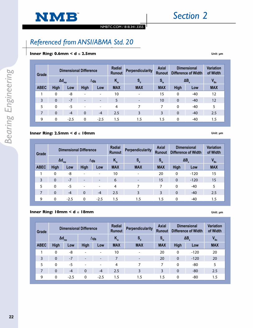
ABEC High Low High Low MAX MAX MAX High Low MAX1 0 -8 - - 10 - 15 0 -40 12
3 0 -7 - - 5 - 10 0 -40 12
5 0 -5 - - 4 7 7 0 -40 5
7 0 -4 0 -4 2.5 3 3 0 -40 2.5
9 0 -2.5 0 -2.5 1.5 1.5 1.5 0 -40 1.5
GradeDimensional Difference Radial
Runout Perpendicularity Axial Runout
Dimensional Difference of Width
Variation of Width
Δdmp ∆ds Kia Sd Sia ΔBs VBs
ABEC High Low High Low MAX MAX MAX High Low MAX1 0 -8 - - 10 - 20 0 -120 15
3 0 -7 - - 6 - 15 0 -120 15
5 0 -5 - - 4 7 7 0 -40 5
7 0 -4 0 -4 2.5 3 3 0 -40 2.5
9 0 -2.5 0 -2.5 1.5 1.5 1.5 0 -40 1.5
GradeDimensional Difference Radial
Runout Perpendicularity Axial Runout
Dimensional Difference of Width
Variation of Width
Δdmp ∆ds Kia Sd Sia ΔBs VBs
ABEC High Low High Low MAX MAX MAX High Low MAX1 0 -8 - - 10 - 20 0 -120 203 0 -7 - - 7 - 20 0 -120 205 0 -5 - - 4 7 7 0 -80 57 0 -4 0 -4 2.5 3 3 0 -80 2.59 0 -2.5 0 -2.5 1.5 1.5 1.5 0 -80 1.5
Inner Ring: 0.6mm < d ≤ 2.5mm
Inner Ring: 2.5mm < d ≤ 10mm
Inner Ring: 10mm < d ≤ 18mm
Referenced from ANSI/ABMA Std. 20 Unit: µm
Unit: µm
Unit: µm

2.1
NMBTC.COM / 818.341.3355NMBTC.COM / 818.341.3355
23
Bearing EngineeringSection 2
GradeDimensional Difference Radial
Runout Perpendicularity Axial Runout
Dimensional Difference of Width
Variation of Width
ΔDmp ΔDs Kea SD Sea ΔCs VCs
ABEC High Low High Low MAX MAX MAX High Low MAX1 0 -8 - - 15 - 15 0 -40 123 0 -7 - - 8 - 10 0 -40 125 0 -5 - - 5 8 8 0 -40 57 0 -4 0 -4 3 4 5 0 -40 2.59 0 -2.5 0 -2.5 1.5 1.5 1.5 0 -40 1.5
GradeDimensional Difference Radial
Runout Perpendicularity Axial Runout
Dimensional Difference of Width
Variation of Width
ΔDmp ΔDs Kea SD Sea ΔCs VCs
ABEC High Low High Low MAX MAX MAX High Low MAX1 0 -8 - - 15 - 20 0 -120 15
3 0 -7 - - 8 - 15 0 -120 15
5 0 -5 - - 5 8 8 0 -40 5
7 0 -4 0 -4 3 4 5 0 -40 2.5
9 0 -2.5 0 -2.5 1.5 1.5 1.5 0 -40 1.5
GradeDimensional Difference Radial
Runout Perpendicularity Axial Runout
Dimensional Difference of Width
Variation of Width
ΔDmp ΔDs Kea SD Sea ΔCs VCs
ABEC High Low High Low MAX MAX MAX High Low MAX1 0 -9 - - 15 - 25 0 -120 203 0 -8 - - 9 - 15 0 -120 205 0 -6 - - 6 8 8 0 -80 57 0 -5 0 -5 4 4 5 0 -80 2.59 0 -4 0 -4 2.5 1.5 2.5 0 -80 1.5
Outer Ring: 2.5mm < D ≤ 6mm
Outer Ring: 6mm < D ≤ 18mm
Outer Ring: 18mm < D ≤ 30mm
Referenced from ANSI/ABMA Std. 20 Referenced from ANSI/ABMA Std. 20.0 Unit: µm
Unit: µm
Unit: µm

2.2
NMBTC.COM / 818.341.3355
Section 2Be
arin
g En
gine
erin
g
24
Tolerances of Flange Width and Tolerance of Rotation Precision related to Flange
D ABEC 1, 3 ABEC 5, 7, 9 ABEC 1, 3 ABEC 5 ABEC 7 ABEC 9
(mm) ∆C1s VC1s
Over Incl. High Low High Low MAX
-40**
-40*** 12**
2.5*
30 0-120
0 -80
15***
5 2.5 1.5
20
D ABEC 5 ABEC 7 ABEC 9 ABEC 5 ABEC 7 ABEC 9
(mm) SD1 Sea1
Over Incl. MAX MAX2.5* 18 8 4 1.5 11 7 3
18 30 8 4 1.5 11 7 4
*D = 2.5mm is included in this dimension division **The values apply only up to and including d = 2.5mm ***The values apply only up to and including d = 10mm
Flange Outside Diameter Tolerance
Unit: µm
Unit: µm
Referenced from JIS B 1514-1
D1 D1s
(mm) Non-Locating Flange Locating Flange
Over Incl. High Low High Low
10 +220 -36 0 -36
10 18 +270 -43 0 -43
18 30 +330 -52 0 -52

2.1
NMBTC.COM / 818.341.3355NMBTC.COM / 818.341.3355
25
Inner ring bore side/outer ring outer diameter side
(Rad
ial d
irect
ion)
Side
face
of
inne
r/out
er ri
ng
(Axial direction)
Bearing
Bearing EngineeringSection 2
Maximum Values of Chamfer Dimension for Radial Bearings
Referenced from JIS B 1514-3
rs mind rs max
Over Incl. Radial Direction Axial Direction
0.05 - - 0.1 0.2
0.08 - - 0.16 0.3
0.1 - - 0.2 0.4
0.15 - - 0.3 0.6
0.2 - - 0.5 0.8
0.3- 40 0.6 1
40 - 0.8 1
0.6- 40 1 2
40 - 1.3 2
1- 50 1.5 3
50 - 1.9 3
Unit: mm
Tolerances of Flange Width and Tolerance of Rotation Precision related to Flange
Referenced from JIS B 1514-1

2.2
NMBTC.COM / 818.341.3355
Section 2Be
arin
g En
gine
erin
g
26
Bore (ds) ....................................................................... Figure 2-1 Outer Diameter (Ds) ................................................. Figure 2-2 Inner Ring Width (Bs) ............................................... Figure 2-3 Outer Ring Width (Cs) .............................................. Figure 2-4 Side Runout of Inner Ring (Sd) ............................... Figure 2-5 Outside Cyl. Surface Runout w/ Side (SD) ..............Figure 2-6 Radial Runout of Inner Ring (Kia) .......................... Figure 2-7 Radial Runout of Outer Ring (Kea) ....................... Figure 2-8 Axial Runout of Inner Ring (Sia) ............................. Figure 2-9 Axial Runout of Outer Ring (Sea) ........................... Figure 2-10
DimensionsBore (ds)
Figure 2-1Measure the amount of change within the radial plane.
Outer Diameter (Ds)
Figure 2-2Measure the amount of change within the radial plane.
Inner Ring Width (Bs)
Figure 2-3Measure while rotating inner ring one revolution.
Outer Ring Width (Cs)
Figure 2-4Measure while rotating outer ring one revolution.
⑧ 測定方法
1 実測内径(ds) 図8-12 実測外径(Ds) 図8-23 実測内輪幅(Bs) 図8-34 実測外輪幅(Cs) 図8-4
転がり玉軸受の寸法及び振れの検証に関する一般原則はJIS B 1515-2 に規定されています。 実測寸法および振れの測定方法の概要を次に示します。
寸法関係 1 内径の軸線に対する内輪側面の直角度 [内輪の横振れ](Sd) 図8-52 側面に対する外輪外径面の直角度 [外径面の倒れ](SD) 図8-63 内輪のラジアル振れ(Kia) 図8-74 外輪のラジアル振れ(Kea) 図8-85 内輪のアキシアル振れ(Sia) 図8-96 外輪のアキシアル振れ(Sea) 図8-10参考 [ ]内は旧JISでの表現。
振れ関係
内輪のラジアル振れ(Kia) 図8-7
外輪のアキシアル振れ(Sea) 図8-10内輪幅(Bs) 図8-3 外輪幅(Cs) 図8-4
外径(Ds) 図8-2内径(ds) 図8-1
ラジアル平面内で角度を変えて測定する。
内輪を1回転させ、測定する。 外輪を1回転させ、測定する。
ラジアル平面内で角度を変えて測定する。
内輪を回転 外輪を回転
内輪側面の直角度(Sd) 図8-5
内輪のアキシアル振れ(Sia) 図8-9
外輪外径面の直角度(SD) 図8-6
内輪を回転
内輪を回転
外輪を回転
外輪を回転
外輪を回転
内輪を回転
内輪を1回転させながら指示計を読む。
外輪のラジアル振れ(Kea) 図8-8
外輪に荷重を負荷し、1回転させながら指示計を読む。
外輪を1回転させながら指示計を読む。
内輪に荷重を負荷し、1回転させながら指示計を読む。
外輪に荷重を負荷し、1回転させながら指示計を読む。内輪に荷重を負荷し、1回転させながら指示計を読む。
26 27
1-4 軸受 の選定
Measurement MethodsGeneral rules regarding verifying ball bearing dimensions and runout are specified in JIS B 1515-2. Please refer to the following for the dimensions and measurement methods of runout.
Rotating inner ring
Rotating outer ring
⑧ 測定方法
1 実測内径(ds) 図8-12 実測外径(Ds) 図8-23 実測内輪幅(Bs) 図8-34 実測外輪幅(Cs) 図8-4
転がり玉軸受の寸法及び振れの検証に関する一般原則はJIS B 1515-2 に規定されています。 実測寸法および振れの測定方法の概要を次に示します。
寸法関係 1 内径の軸線に対する内輪側面の直角度 [内輪の横振れ](Sd) 図8-52 側面に対する外輪外径面の直角度 [外径面の倒れ](SD) 図8-63 内輪のラジアル振れ(Kia) 図8-74 外輪のラジアル振れ(Kea) 図8-85 内輪のアキシアル振れ(Sia) 図8-96 外輪のアキシアル振れ(Sea) 図8-10参考 [ ]内は旧JISでの表現。
振れ関係
内輪のラジアル振れ(Kia) 図8-7
外輪のアキシアル振れ(Sea) 図8-10内輪幅(Bs) 図8-3 外輪幅(Cs) 図8-4
外径(Ds) 図8-2内径(ds) 図8-1
ラジアル平面内で角度を変えて測定する。
内輪を1回転させ、測定する。 外輪を1回転させ、測定する。
ラジアル平面内で角度を変えて測定する。
内輪を回転 外輪を回転
内輪側面の直角度(Sd) 図8-5
内輪のアキシアル振れ(Sia) 図8-9
外輪外径面の直角度(SD) 図8-6
内輪を回転
内輪を回転
外輪を回転
外輪を回転
外輪を回転
内輪を回転
内輪を1回転させながら指示計を読む。
外輪のラジアル振れ(Kea) 図8-8
外輪に荷重を負荷し、1回転させながら指示計を読む。
外輪を1回転させながら指示計を読む。
内輪に荷重を負荷し、1回転させながら指示計を読む。
外輪に荷重を負荷し、1回転させながら指示計を読む。内輪に荷重を負荷し、1回転させながら指示計を読む。
26 27
1-4 軸受 の選定

1.5
NMBTC.COM / 818.341.3355NMBTC.COM / 818.341.3355
Section 2
27
Bearing Engineering
Radial Runout of Outer Ring (Kea)
Figure 2-8Read the indicator while rotating outer ring one revolution with dead weight placed on outer ring.
Axial Runout of Inner Ring (Sia)
Figure 2-9Read the indicator while rotating inner ring one revolution with dead weight placed on inner ring.
Axial Runout of Outer Ring (Sea)
Figure 2-10Read the indicator while rotating outer ring one revolution with dead weight placed on outer ring.
Side Runout of Inner Ring (Sd)
Figure 2-5Read the indicator while rotating inner ring one revolution.
Outside Cylindrical Surface Runout
with Side (SD)
Figure 2-6Read the indicator while rotating outer ring one revolution.
Radial Runout of Inner Ring (Kia)
Figure 2-7Read the indicator while rotating inner ring one revolution with dead weight placed on inner ring.
Runout
Rotating inner ring
Rotating inner ring
Rotating inner ring Rotating outer ring
Rotating outer ring
Rotating outer ring

NMBTC.COM / 818.341.3355
Section 2Be
arin
g En
gine
erin
g
28
Clearance Symbols Clearance (µm)
P13 2.5 ~ 7.5
P24 5.0 ~ 10.0
P25* 5.0 ~ 12.5
P58 12.5 ~ 20.0
Clearance Symbols Clearance (µm)
M2 3 ~ 8
M3* 5 ~ 10
M4 8 ~ 13
M5 13 ~ 20
Moment Clearance ( )
Figure 2-13The angular displacement generated by tilting the inner ring in the axial direction while securing the outer ring.
*Standard
Internal Clearance The radial internal clearance of a ball bearing affects life, noise, vibration, and heat generation. It is important to select the appropriate internal clearance for each application.
The three types of internal clearance of a ball bearing are radial clearance, axial clearance, and moment clearance.
Radial internal clearance decreases when a ball bear-ing is fitted to either a shaft or housing with interfer-ence. Radial internal clearance is a specified value in the NMB or JIS part number, as shown in the follow-ing tables.
The fits and temperature affect the radial internal clearance. Therefore, actual application conditions need to be reviewed when radial internal clearance is selected.
Radial Clearance (Gr)
Figure 2-11The displacement generated by moving the outer ring in the radial direction while securing the inner ring.
Axial Clearance (Gt)
Figure 2-12The displacement generated by moving the inner ring in the axial direction while securing the outer ring.
Radial Clearance of NMB Part Number
Radial Internal Clearance
O
Load
Load
Radial Clearance of JIS Part Number

2.1
NMBTC.COM / 818.341.3355NMBTC.COM / 818.341.3355
29
Bearing EngineeringSection 2
FitsWhen a ball bearing is used, it is not used only by itself. It is always fitted to either a shaft or a housing bore. Fit is the value of tightness between the shaft and bearing bore when the bearing is installed. Fit can also be the tightness between the housing bore and the bearing outside diameter. Fits are classified into clearance fit, intermediate fit, and transition fit.
Fits Fits prevent bearings from having unfavorable slip called “Creep” by firmly securing the inner ring and outer ring on the shaft and in the housing, respectively. Fits also minimize vibration during rotation. When creep happens, abnormal heat and wear particles can be generated. Abnormal heat hastens the degradation of grease and retainers. Wear particles could migrate inside the bearing, and cause vibration and surface degradation. It is necessary to choose a proper fit for each application because improper fits can not only degrade the bearing performance, but also they could cause seizure due to heat generation and premature failure. In the case of interference fits, the interference causes a change in radial internal clearance. The change in radial clearance generated by interference can be calculated as shown below.
Decrease in Internal Clearance Due to Fits Interference Fit of the Inner Ring to the Shaft
The sketches drawn in solid lines and dotted lines are the bearing prior to fit, and the bearing after fit, respectively. When press fit with an interference ( i ) the inner ring groove diameter (d2) increases by an amount (δ). This value (δ) is also equal to the decrease in radial internal clearance.
Pressfitsoftheinnerringtotheshaft:
d: Nominal Bore Diameter Nominal Outside Diameter of the Shaftd1: Shaft Bore
(In the case of Solid Shafts: = 1)
d2: Inner Ring Groove Diameteri: Interference (i/2 in radial direction)Eb: Young’s Modulus of Inner Ring (outer ring)Es: Young’s Modulus of Shaft Materialmb: Poisson’s Ratio of Inner Ring (outer ring)ms: Poisson’s Ratio of Shaft Material
(d/d1)2+1
(d/d1)2-1
δ =
(d2/d)2−1(d2/d)2-1
(d2/d)2+1+ mb
1 (d/d1)2-1
(d/d1)2+1− ms
1ES
Eb+
2i(d2/d)

NMBTC.COM / 818.341.3355
Section 2Be
arin
g En
gine
erin
g
30
Interference Fit of the Outer Ring to the Housing
The sketches drawn in solid lines and dotted lines are the bearing prior to fit, and the bearing after fit, respectively. When it is press fit with an interference ( I ) the outer ring groove diameter D1 decreases by an amount (∆). This amount (∆) is also equal to the decrease in radial clearance.
Press fits of the inner ring to the housing:
Securing with AdhesiveWhen the bearing is fit to the shaft and housing with adhesive without interference, it is necessary to select the proper clearance to enhance the effectiveness of the adhesive. It is recommended to consult with the adhesive manufacturer because the proper clearance depends on the type of adhesive. Please be aware that the roundness of the ring raceways could deteriorate due to the curing stress of the adhesive.
Referenced from JIS B 0401-1Deviation of Holes for Common Fits
Nominal Dimensions (mm) G H JS K M N POver Incl. G7 H5 H6 H7 JS5 JS6 JS7 K5 K6 K7 M5 M6 M7 N6 N7 P7
- 3+12 +4 +6 +10
±2 ±3 ±50 0 0 -2 -2 -2 -4 -4 -6
+2 0 0 0 -4 -6 -10 -6 -8 -12 -10 -14 -16
3 6+16 +5 +8 +12
±2.5 ±4 ±60 +2 +3 -3 -1 0 -5 -4 -8
+4 0 0 0 -5 -6 -9 -8 -9 -12 -13 -16 -20
6 10+20 +6 +9 +15
±3 ±4.5 ±7.5+1 +2 +5 -4 -3 0 -7 -4 -9
+5 0 0 0 -5 -7 -10 -10 -12 -15 -16 -19 -24
10 18+24 +8 +11 +18
±4 ±5.5 ±9+2 +2 +6 -4 -4 0 -9 -5 -11
+6 0 0 0 -6 -9 -12 -12 -15 -18 -20 -23 -29
18 30+28 +9 +13 +21
±4.5 ±6.5 ±10.5+1 +2 +6 -5 -4 0 -11 -7 -14
+7 0 0 0 -8 -11 -15 -14 -17 -21 -24 -28 -35
Δ = (D/D1)2−1
(D/D1)2−1
(D/D1)2+1− mb
1(D2/D)2 −1
(D2/D)2 +1++ mh
1Eh
Eb
2 I (D/D1)
D: Nominal outside fiameter of outer ring, Nominal housing boreD1: Outer ring groove diameterD2: Housing outer diameterI: Interference (I/2 in radial direction)Eh: Young’s Modulus of housing materialmh: Poisson’s Ratio of housing material
Unit: µm
Housing

2.1
NMBTC.COM / 818.341.3355NMBTC.COM / 818.341.3355
31
Bearing EngineeringSection 2
Unit: µmDeviation of Shafts for Common Fits
Nominal Dimensions (mm) f g h js k m n p rOver Incl. f6 g5 g6 h4 h5 h6 js4 js5 js6 k4 k5 k6 m5 m6 n6 p6 r6
- 3-6 -2 -2 0 0 0
±1.5 ±2 ±3+3 +4 +6 +6 +8 +10 +12 +16
-12 -6 -8 -3 -4 -6 0 0 0 +2 +2 +4 +6 +10
3 6-10 -4 -4 0 0 0
±2 ±2.5 ±4+5 +6 +9 +9 +12 +16 +20 +23
-18 -9 -12 -4 -5 -8 +1 +1 +1 +4 +4 +8 +12 +15
6 10-13 -5 -5 0 0 0
±2 ±3 ±4.5+5 +7 +10 +12 +15 +19 +24 +28
-22 -11 -14 -4 -6 -9 +1 +1 +1 +6 +6 +10 +15 +19
Unit: µm
Unit: µm
Stationary Outer Ring LoadThe line of action of the load does not rotate in relation to the outer ring of the bearing
Rotating Outer Ring LoadThe line of action of the load is rotating in relation to the outer ring of the bearing
Indeterminate Direction LoadThe direction of the load cannot be determined
Referenced from JIS B 1566Fits of Inner Ring in Radial Bearings*
Fits of Outer Ring in Radial Bearings*
*Tolerance of Bearing Bore is based on JIS B 1514-1.
**Symbol of Tolerance Zone Class is based on JIS B 0401.
***Tolerance of Outer Diameter of Bearings is based on JIS B1514-1.
Definitions
Rotating Inner Ring Load The line of action of the load is rotating in relation to the inner ring of the bearing
Stationary Inner Ring LoadThe line of action of the load does not rotate in relation to the inner ring of the bearing
Bearing ABEC Rating
Rotating inner ring load or indeterminate direction load Stationary inner ring loadTolerance zone class of shaft**
ABEC 1 r6 p6 n6 m6 k6 js6 h5 h6 g6 f6
ABEC 3 r6 p6 n6 m5 k5 js5 h5 h5 g5 f6
ABEC 5 - - - m5 k4 js4 h4 h5 - -
Fits Interference Intermediate Clearance
Bearing ABEC Rating
Stationary outer ring load Indeterminate direction load or rotating outer ring loadTolerance zone class of hole**
ABEC 1 G7 H7 JS7 - JS7 K7 M7 N7 P7
ABEC 3 G7 H6 JS6 - JS6 K6 M6 N6 P7
ABEC 5 - H5 JS5 K5 - K5 M5 - -
Fits Interference fit Intermediate fit Clearance fit

NMBTC.COM / 818.341.3355
Section 2Be
arin
g En
gine
erin
g
32
Shaft and Housing
Finish Precision of Shaft & HousingWhen the bearings are installed, roundness of the bearings is degraded if the precision and surface roughness of the shaft and housing are not at satisfactory levels.
Fillet Radii of Corners of Shaft & HousingThe side faces of the shafts and housing (areas contact-ing the bearing’s side face) should be at right angles to the shaft center line and fit surfaces. The maximum permissible radius (ras max) of the fillet radii of the shaft and housing corners is smaller than or equal to the minimum permissible chamfer dimensions of the bearings.
Unit: µm
Height of ShoulderThe height of the shaft and housing shoulders must be taller than the minimum permissible chamfer dimensions. They also need to contact the side faces of the bearing inner and outer rings.
The minimum height of the housing shoulder (h), must be four times the chamfer dimension (ras). Please refer to the table below and Figure 2-14 for dimensions.
Designs of Shaft and Housing
Referenced from JIS B 1566
The shaft and housing dimensions and precision should be carefully designed to optimize the performance of the bearing in the application.
Figure 2-14
s min
s min
as max
as max
h
h
The height of outer ring shoulder
The height of outer ring shoulder
Housing
Shaft
*The shoulder height needs to be greater than this when axial load applied is significant.**This is used when axial load applied is insignificant.***This is not specified in JIS B 1566.
Chamfer Dimensions of Inner and Outer Ring
Shaft and HousingRadii of Rounding Corners General Case * Particular Case **
r s min ras max h (min)0.05*** 0.05 0.2 0.2
0.08*** 0.08 0.3 0.3
0.1 0.1 0.4 0.4
0.15 0.15 0.6 0.6
0.2 0.2 0.8 0.8
0.3 0.3 1.25 1
NMBTC.COM / 818.341.3355NMBTC.COM / 818.341.3355
33
Bearing EngineeringSection 2
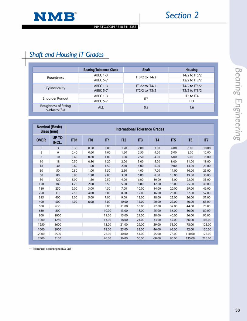
Shaft and Housing IT Grades
***Tolerances according to ISO 286
Bearing Tolerance Class Shaft Housing
RoundnessABEC 1-3 IT3/2 to IT4/2 IT4/2 to IT5/2ABEC 5-7 IT2/2 to IT3/2
Cylindricality ABEC 1-3 IT3/2 to IT4/2 IT4/2 to IT5/2ABEC 5-7 IT2/2 to IT3/2 IT2/2 to IT3/2
Shoulder RunoutABEC 1-3
IT3IT3 to IT4
ABEC 5-7 IT3Roughness of fitting
surfaces (Ra)ALL 0.8 1.6
Nominal (Basic) Sizes (mm) International Tolerance Grades
OVER UP TO INCL. IT01 IT0 IT1 IT2 IT3 IT4 IT5 IT6 IT7
0 3 0.30 0.50 0.80 1.20 2.00 3.00 4.00 6.00 10.003 6 0.40 0.60 1.00 1.50 2.50 4.00 5.00 8.00 12.006 10 0.40 0.60 1.00 1.50 2.50 4.00 6.00 9.00 15.00
10 18 0.50 0.80 1.20 2.00 3.00 5.00 8.00 11.00 18.0018 30 0.60 1.00 1.50 2.50 4.00 6.00 9.00 13.00 21.0030 50 0.80 1.00 1.50 2.50 4.00 7.00 11.00 16.00 25.0050 80 0.80 1.20 2.00 3.00 5.00 8.00 13.00 19.00 30.0080 120 1.00 1.50 2.50 4.00 6.00 10.00 15.00 22.00 35.00
120 180 1.20 2.00 3.50 5.00 8.00 12.00 18.00 25.00 40.00180 250 2.00 3.00 4.50 7.00 10.00 14.00 20.00 29.00 46.00250 315 2.50 4.00 6.00 8.00 12.00 16.00 23.00 32.00 52.00315 400 3.00 5.00 7.00 9.00 13.00 18.00 25.00 36.00 57.00400 500 4.00 6.00 8.00 10.00 15.00 20.00 27.00 40.00 63.00500 630 9.00 11.00 16.00 22.00 32.00 44.00 70.00630 800 10.00 13.00 18.00 25.00 36.00 50.00 80.00800 1000 11.00 15.00 21.00 28.00 40.00 56.00 90.00
1000 1250 13.00 18.00 24.00 33.00 47.00 66.00 105.001250 1600 15.00 21.00 29.00 39.00 55.00 78.00 125.001600 2000 18.00 25.00 35.00 46.00 65.00 92.00 150.002000 2500 22.00 30.00 41.00 55.00 78.00 110.00 175.002500 3150 26.00 36.00 50.00 68.00 96.00 135.00 210.00

NMBTC.COM / 818.341.3355
Section 2Be
arin
g En
gine
erin
g
34
PreloadThe purpose of applying preload to a bearing is to improve the runout precision of the rotating axis, and to reduce vibration and noise. It is important to select the proper amount of preload and method for each application. Otherwise, bearing performance such as life, noise, and vibration will be degraded. Excessive heat could also be generated.
The Purpose of PreloadThe necessary radial internal clearance in an assembled ball bearing may increase noise and rotational vibration in an application due to the movement of the balls inside the bearings. To combat the relative movement of the balls, an axial “preload” should be applied to the bearing, as shown in the diagram below. Preload increases the stiffness of the bearing and reduces potential noise and vibration.
The appropriate preload force depends on the size of the ball bearing. Higher preload will increase the bearing stiff-ness but excessive preload may result in premature failures. If insufficient preload is applied, vibration and fretting wear may occur inside of the bearing.
Optimum PreloadMinebea recommends an optimum preload based on the calculation of the optimum surface stress. When the preload is applied to the ball bearing, a contact ellipse is generated as a result of elastic deformation of the contact areas between the balls and raceways. The surface stress is given by dividing the loads, Q (ball loads), which are generated in the perpen-dicular direction at the contacts between the balls and race-ways, by the surface areas of the contact ellipses.
In Figure 2-15, the contact ellipse area (S) between the balls and raceways is formulated as: S = πab (a: the major axis of the contact ellipse area, b: the minor axis of the contact ellipse area). P represents the average surface
Q
Q
stress, and Q represents the loads generated in the perpen-dicular direction at the contact areas between the balls and raceways.
P = Q / S [MPa]
If the preload is the dominant load applied to the bearing, the guideline to meet the noise life is as follows.
• Over 10,000 hours noise life requirement. The specific preload should not generate an average surface contact stress (P) higher than 800MPa.
• 5,000 - 10,000 hours noise life requirement (general products) The specific preload should be generating an average surface contact stress (P) of roughly 1,000MPa.
• Less than 5,000 hours noise life requirement (critical stiffness application) The specific preload should be generating an average surface contact stress (P) of roughly 1,500MPa.
Simple calculation of preload using dynamic load rating (Cr)
• Over 10,000 hours noise life requirement: 0.5/100Cr - 1/100Cr• 5,000 - 10,000 hours noise life requirement: 1/100Cr - 1.5/100Cr• Less than 5,000 hours noise life requirement: 1.5/100Cr - 2/100Cr
Maximum Permissible LoadIn general, a permanent deformation will occur if the average surface stress generated on high carbon chromium steel is greater than 2,700 MPa. So, even for a very short period of time, the loads should not generate greater than 2,700 MPa of average surface stress. Based on our experience, the loads applied to the bearing should not generate more than 1,600 MPa of average surface stress. Besides preload, other types of loads should also be considered because they could generate surface stress.
Preload and StiffnessThere are two basic methods of preloading: Solid Preload (Figure 2-16) and Spring Preload (Figure 2-17) shown on the following pages.
Solid Preload can be obtained by mechanically locking all of the rings in position. The advantages of this type of design are simplicity and high stiffness. However, expansion and shrinkage of the components due to temperature change can cause changes in preload.
Figure 2-15

NMBTC.COM / 818.341.3355NMBTC.COM / 818.341.3355
35
Bearing EngineeringSection 2
DisplacementWhen the loads are applied to the bearings, the dis-placement takes place at the contact points between the balls and raceways.
Radial DisplacementWhen the loads are applied in radial directions as shown in Figure 2-20, Q is expressed as:
(Fr, Q, and Z represent a radial load, the maximum load applied to the balls, and the number of balls, respectively.) Radial displacement at the contact points between balls and raceways is expressed below.
eδ : Coefficient based on the relationship between balls and racewaysΣρ : Total major curvature
In order to determine the total displacement, the displace-ment between the balls inner ring and outer ring needs to be summed because the balls are contacting both the inner ring and outer rings.
δr : Total radial displacementδi : Radial displacement between balls and inner ring racewayδe : Radial displacement between balls and outer ring raceway
Total displacement is represented as follows: δr = δi + δe
Figure 2-20
Axial Displacement
Axial displacement (Fa) can be calculated in the following series of calculations:
Initial Contact Angle (α0)
For a bearing with the radial internal clearance (Gr) eliminated from an axial load, the initial contact angle can be calculated as follows.
Q = Fr5_Z
The components could also wear, and eventually the preloads could be reduced.
Spring Preload (constant pressure preload) can be applied by using a coil spring, wave spring, etc. An advantage of spring preload is stability despite tem-perature variation. The disadvantages are complexity and low stiffness.
The preload can be applied in two directions: Duplex Face to Face (DF) (Figure 2-18) and duplex Back to Back (DB) (Figure 2-19). The stiffness is higher in DB.
Preload MethodSolid Preload
Figure 2-16
Spring Preload
Figure 2-17
Preload DirectionDuplex Face to Face (DF)
Figure 2-18
Duplex Back to Back (DB)
Figure 2-19
(Σρ)Q2δ=eδ 3
NMBTC.COM / 818.341.3355
Section 2Be
arin
g En
gine
erin
g
36
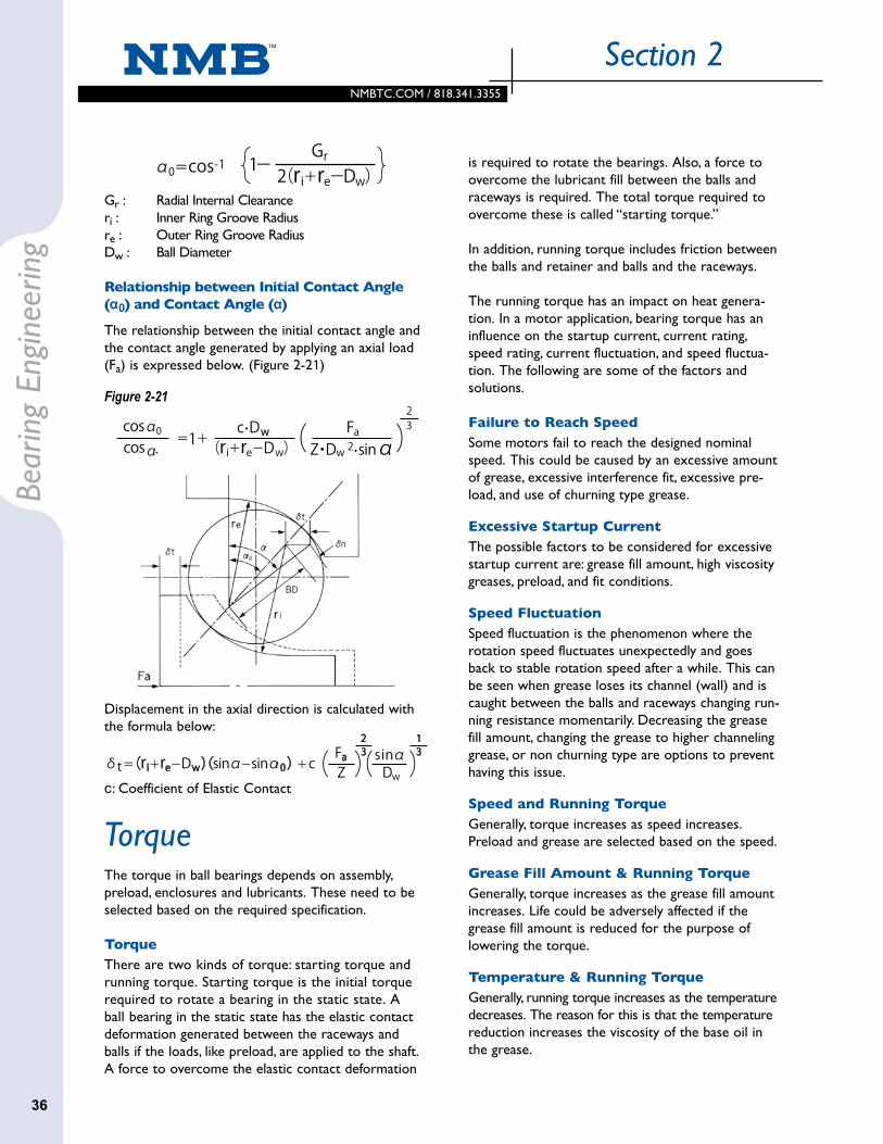
Gr : Radial Internal Clearanceri : Inner Ring Groove Radiusre : Outer Ring Groove RadiusDw : Ball Diameter
Relationship between Initial Contact Angle (α0) and Contact Angle (α)
The relationship between the initial contact angle and the contact angle generated by applying an axial load (Fa) is expressed below. (Figure 2-21)
Figure 2-21
Displacement in the axial direction is calculated with the formula below:
c: Coefficient of Elastic Contact
The torque in ball bearings depends on assembly, preload, enclosures and lubricants. These need to be selected based on the required specification.
TorqueThere are two kinds of torque: starting torque and running torque. Starting torque is the initial torque required to rotate a bearing in the static state. A ball bearing in the static state has the elastic contact deformation generated between the raceways and balls if the loads, like preload, are applied to the shaft. A force to overcome the elastic contact deformation
Torque
is required to rotate the bearings. Also, a force to overcome the lubricant fill between the balls and raceways is required. The total torque required to overcome these is called “starting torque.”
In addition, running torque includes friction between the balls and retainer and balls and the raceways.
The running torque has an impact on heat genera-tion. In a motor application, bearing torque has an influence on the startup current, current rating, speed rating, current fluctuation, and speed fluctua-tion. The following are some of the factors and solutions.
Failure to Reach SpeedSome motors fail to reach the designed nominal speed. This could be caused by an excessive amount of grease, excessive interference fit, excessive pre-load, and use of churning type grease.
Excessive Startup CurrentThe possible factors to be considered for excessive startup current are: grease fill amount, high viscosity greases, preload, and fit conditions.
Speed FluctuationSpeed fluctuation is the phenomenon where the rotation speed fluctuates unexpectedly and goes back to stable rotation speed after a while. This can be seen when grease loses its channel (wall) and is caught between the balls and raceways changing run-ning resistance momentarily. Decreasing the grease fill amount, changing the grease to higher channeling grease, or non churning type are options to prevent having this issue.
Speed and Running TorqueGenerally, torque increases as speed increases. Preload and grease are selected based on the speed.
Grease Fill Amount & Running TorqueGenerally, torque increases as the grease fill amount increases. Life could be adversely affected if the grease fill amount is reduced for the purpose of lowering the torque.
Temperature & Running TorqueGenerally, running torque increases as the temperature decreases. The reason for this is that the temperature reduction increases the viscosity of the base oil in the grease.
NMBTC.COM / 818.341.3355NMBTC.COM / 818.341.3355
37
Bearing EngineeringSection 2
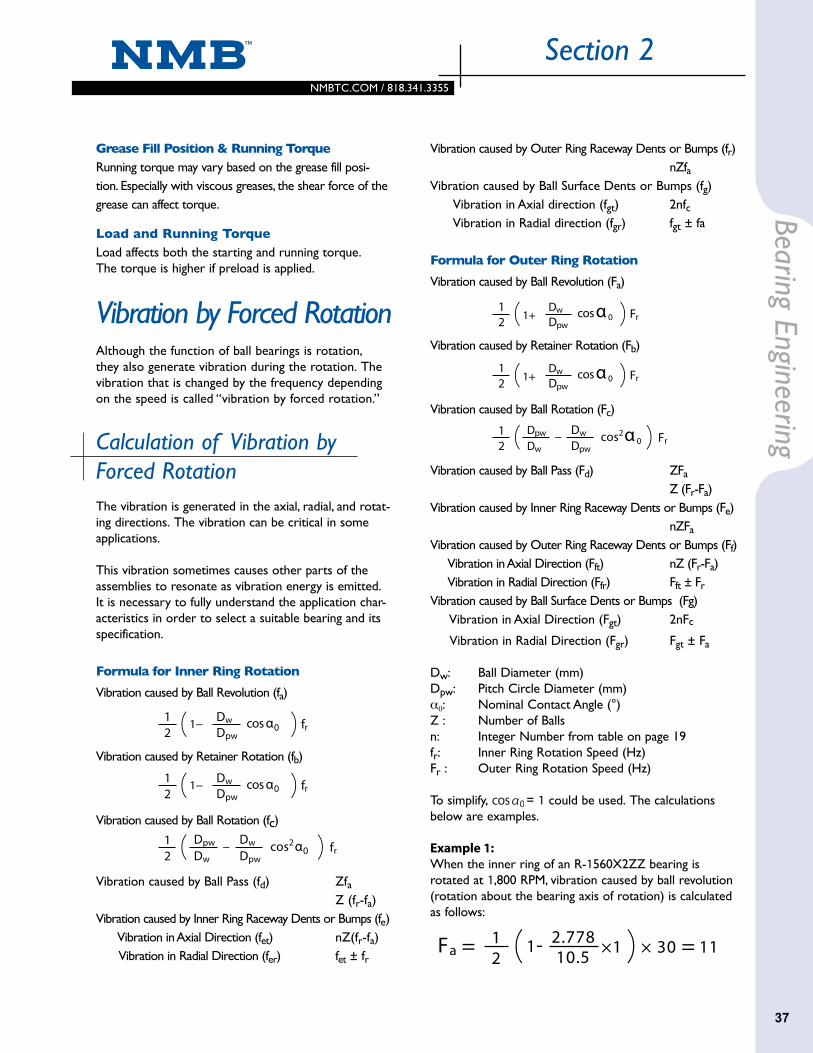
2Fa = 1 1-
10.52.778 ×1 × 30 = 11
Vibration caused by Outer Ring Raceway Dents or Bumps (fr) nZfaVibration caused by Ball Surface Dents or Bumps (fg) Vibration in Axial direction (fgt) 2nfc Vibration in Radial direction (fgr) fgt ± fa
Formula for Outer Ring Rotation
Vibration caused by Ball Revolution (Fa)
Vibration caused by Retainer Rotation (Fb)
Vibration caused by Ball Rotation (Fc)
Vibration caused by Ball Pass (Fd) ZFa
Z (Fr-Fa)Vibration caused by Inner Ring Raceway Dents or Bumps (Fe) nZFa
Vibration caused by Outer Ring Raceway Dents or Bumps (Ff) Vibration in Axial Direction (Fft) nZ (Fr-Fa) Vibration in Radial Direction (Ffr) Fft ± Fr
Vibration caused by Ball Surface Dents or Bumps (Fg) Vibration in Axial Direction (Fgt) 2nFc
Vibration in Radial Direction (Fgr) Fgt ± Fa
Dw: Ball Diameter (mm)Dpw: Pitch Circle Diameter (mm)α0: Nominal Contact Angle (°)Z : Number of Ballsn: Integer Number from table on page 19fr: Inner Ring Rotation Speed (Hz)Fr : Outer Ring Rotation Speed (Hz)
To simplify, = 1 could be used. The calculations below are examples.
Example 1: When the inner ring of an R-1560X2ZZ bearing is rotated at 1,800 RPM, vibration caused by ball revolution (rotation about the bearing axis of rotation) is calculated as follows:
Grease Fill Position & Running TorqueRunning torque may vary based on the grease fill posi-tion. Especially with viscous greases, the shear force of the grease can affect torque.
Load and Running TorqueLoad affects both the starting and running torque. The torque is higher if preload is applied.
Vibration by Forced RotationAlthough the function of ball bearings is rotation, they also generate vibration during the rotation. The vibration that is changed by the frequency depending on the speed is called “vibration by forced rotation.”
Calculation of Vibration by Forced RotationThe vibration is generated in the axial, radial, and rotat-ing directions. The vibration can be critical in some applications.
This vibration sometimes causes other parts of the assemblies to resonate as vibration energy is emitted. It is necessary to fully understand the application char-acteristics in order to select a suitable bearing and its specification.
Formula for Inner Ring Rotation
Vibration caused by Ball Revolution (fa)
Vibration caused by Retainer Rotation (fb)
Vibration caused by Ball Rotation (fc)
Vibration caused by Ball Pass (fd) Zfa Z (fr-fa)Vibration caused by Inner Ring Raceway Dents or Bumps (fe) Vibration in Axial Direction (fet) nZ(fr-fa) Vibration in Radial Direction (fer) fet ± fr
cos α 02Fr
11+
−
Dpw
Dw
cos2 α 02Fr
1 Dpw
Dw Dpw
Dw
cos α 02fr
1 1−
−
Dpw
Dw
cos2 α 02fr
1 Dpw
Dw Dpw
Dw
cos α 02fr
1 1−
−
Dpw
Dw
cos2 α 02fr
1 Dpw
Dw Dpw
Dw
cos α 02fr
1 1−
−
Dpw
Dw
cos2 α 02fr
1 Dpw
Dw Dpw
Dw
cos α 02Fr
11+
−
Dpw
Dw
cos2 α 02Fr
1 Dpw
Dw Dpw
Dw
cos α 02Fr
11+
−
Dpw
Dw
cos2 α 02Fr
1 Dpw
Dw Dpw
Dw

2.2
NMBTC.COM / 818.341.3355
Section 2Be
arin
g En
gine
erin
g
38
The detected vibration is classified into three different frequency bands. The unit for the Anderon meter is referred to as the Anderon value.
NoiseNoise level is checked by an Anderon meter, which is explained below.
Anderon Meter
It is impossible to see the interior of the bearing once it is assembled. The noise levels of bearings must be checked when they are rotating. The Anderon meter checks the noise of assembled bearings and displays the noise level. In order to accurately perform the noise evaluation, the bearings are preloaded. The bearing’s inner ring is rotated at 1,800 RPM and the outer ring is stationary during the measurement. Mechanical vibration of the bearings outer ring is detected in the radial direction by contacting the outer ring with a velocity sensor. The signal from the sensor is converted to a variable electrical output. It is possible to detect even small vibrations because a direct detection system is used instead of a system that converts from rotational vibrations to air vibra-tions. Vibration from other sources can be eliminated in this method.
Spring
Pusher
Preload
Pickup
Spindle
Bearing
1800min-1
Range Frequency Range (Hz)L : Low Band 50 ~ 300
M : Medium Band 300 ~ 1,800
H : High Band 1,800 ~ 10,000

2.1
NMBTC.COM / 818.341.3355NMBTC.COM / 818.341.3355
39
Bearing EngineeringSection 2
Some plastics are susceptible to degradation and cracking due to the lubrication used in ball bearings. Minebea does chemical tests for plastics and grease compatibility.
Chemical AttackDepending on the chemical compatibility, plastic parts such as housings in some application could be degraded by the grease inside the bearings or rust preventative oils on the exterior.
This phenomenon is called a chemical attack. A chem-ical attack can occur in some combinations of plastic materials and lubricants. There are many factors that affect the chemical attacks.
When some physical force is applied to the plastics, grease penetration can cause the chemical attacks.
Stress of Plastic PartsInternal residual stress can occur within injection molded plastic parts. This can be relieved by a secondary process such as machining or ultra sonic adhesion. Although internal residual stress decreases slowly by gradual alleviation and annealing treatments, it is difficult to remove completely.
Oil and GreaseEster is a common base oil of grease. Compared to other types of oil, chemical attacks occur in ester oil more often because it tends to penetrate plastics easily. Some types of oil such as Synthetic Hydrocarbon, Silicone, and Fluorinated resist oil penetration more effectively.
Weld LineIn injection molding, weld lines may reduce the mechanical strength of the part, leaving them vulner-able to penetration and chemical compatibility issues with the lubricant. Interference fit may also present issues at the weld lines.
Compatibility with Plastic PartsPlastic MaterialsWhile chemical attack tends to occur more in non-crystalline plastics (PS: Polyethylene, ABS, PC: Polycarbonate), crystalline plastics (PP: Polypropylene, PE: Polyethylene, POM: Polyacetal) have stronger resistance against chemical attack. Lubricants penetrate into intermolecular spaces more in non-crystalline plastics, and intermolecular bonding tends to break easily.
Plastic CompatibilityPlastic compatibility issues are less common if the internal stress is reduced and the appropriate grease is selected. Minebea has developed synthetic greases that provide improved resistance against plastic compatibility issues.

NMBTC.COM / 818.341.3355
NotesPlastic CompatibilityPlastics are now used more frequently for assemblies using ball bearings due to the trends toward smaller and lighter devices. Unfavorable combinations of grease and plastics could result in a chemical reaction that degrades and cracks components.
When selecting lubrication, application conditions and environment need to be reviewed. Please refer to the Application Guide on the following page for details.
ConductivityConductive grease is available for specific applications. Conductive capability depends on the application condi-tions (Speed, Load, etc.). Please note that the grease life and conductivity life are not equivalent.
Section 2Be
arin
g En
gine
erin
g
40
LubricantsLubricant selection has a strong impact on ball bearing performance. Bearing performance such as life, torque, rotation stability, and noise depends on lubricants even if the bearings use the same material and components.
Bearings are typically filled with either grease or oil. After the initial fill, the grease or oil is rarely changed or replenished. Generally, grease is standard in enclo-sure type bearings (bearings with seals or shields) because the life of grease is longer than that of oils.
Grease is composed of thickener and base oil. Fiber bonding and oil separation of the thickener plays an important role in grease. Fiber bonding keeps the oils in, and the oils are released gradually by oil separation. If only oils were filled in the bearings, they would tend to leak out of the bearing. The slow release of base oils due to oil separation makes longer lubrication life possible. When an application requires extremely low torque or torque fluctuations needs be minimized, oils are the preferred choice. This is because oils spread more than grease but greases are semi-solid and could add resistance against rotation. Grease performance may be enhanced by additives such as oxidation-resis-tant agents, lube agents (improving boundary lubrica-tion), extreme pressure agents, and rust-inhibitor agents.
Lubricant Fill AmountThe standard lubricant fill amount for small and minia-ture size bearings is 25-35%. Grease fill amount varies in each application, and is specified as follows.
Lubricant Fill Amount
Fill Amount Symbols Fill AmountX 5 ~ 10%
L 10 ~ 15%
T 15 ~ 20%
No Code (Standard) 25 ~ 35%
H 40 ~ 50%
J 50 ~ 60%

NMBTC.COM / 818.341.3355NMBTC.COM / 818.341.3355
41
Bearing EngineeringSection 2
* These values shown are typical.
**These ranges are based on the information given by each grease manufacturer.
Please note that they are not the specific temperature ranges for bearing application.
Table of Commonly Used Lubricant Types
Application Guide
Grease Type Lithium Soap Grease Urea Grease Fluorinated Grease Conductive Grease OilThickener Lithium Soap Urea PTFE Carbon -
Base Oil EsterSyn-thetic Hydro- carbon
Ester
FluorinatedFluori-nated
+ EsterSynthetic Hydrocarbon Ester
Syn-thetic
Hydro- carbon
NMB Code LY121 LY72 LY552 LY551 LY532 LY500 LY586 LY699 LY655 LY727 LY707 LY722 LO1 LY650Base Oil Viscosity
[mm2/S@40˚C]26 15 55 48 100 190 85 210 85 148 420 20 12 32
Worked Penetration* 250 275 240 225 255 280 280 280 280 235 263 263 - -
Temperature Range**
[˚C]-50 ~
+150-50 ~
+150-40 ~
+130-40 ~
+200-40 ~
+180-50 ~
+260-50 ~
+220-40 ~
+200-50 ~
+200-40 ~
+125-40 ~
+125-40 ~
+125-50 ~
+120-40 ~
+130
NMB Code LY121 LY72 LY552 LY551 LY532 LY500 LY586 LY699 LY655 LY727 LY707 LY722 LO1 LY650Noise BETTER BETTER BETTER BETTER FAIR FAIR GOOD GOOD FAIR POOR POOR POOR BETTER BETTER
Torque BETTER BETTER GOOD GOOD FAIR FAIR BETTER BEST FAIR FAIR POOR FAIR BETTER BETTER
High Temperature
GOOD FAIR BETTER BETTER BETTER BEST BEST BEST BEST BETTER BEST GOOD FAIR FAIR
Low Temperature GOOD BETTER GOOD GOOD FAIR FAIR BETTER BEST FAIR GOOD GOOD GOOD BETTER BETTER
High Speed GOOD FAIR GOOD BETTER BETTER FAIR FAIR FAIR FAIR FAIR FAIR FAIR FAIR FAIR
Plastic Compatability POOR POOR POOR BETTER POOR FAIR - - BETTER BETTER - - POOR BETTER
Cost Performance BETTER BETTER GOOD BETTER GOOD POOR POOR POOR FAIR FAIR POOR FAIR FAIR GOOD

2.2
NMBTC.COM / 818.341.3355
Section 2Be
arin
g En
gine
erin
g
42
Handling of a BearingBall bearings can be damaged from improper handling or installation. This may shorten the life due to noise, vibration, and heat generation. Careful handling is also required during shipping and storing. If adhesive needs to be used, please use it with a full understand-ing of its characteristics.
Ball bearings favor clean environments as they are very precise mechanical parts. Please maintain clean environments for their usage.
Installation of a Ball BearingThere are many methods to install bearings onto shafts or into housings. The following are important for the installation process.
When bearings are assembled to either shafts or housings, by any fit methods, their centers must be aligned (Figure 2-28). If an interference fit is used, the pressing force has to be applied to either the inner ring or outer ring side face at a right angle. Apply the load slowly and continuously without the use of a shock or impact load.
Brinelling damage can occur when loads are applied in the wrong positions and/or when excessive loads due to misalignment are applied to the bearing during installation. If the bearing has enclosures, installation loads should not be applied to them.
Handling of Shafts and HousingsIf shafts and housings are contaminated, bearing mis-alignment may occur during the installation (Figure 2-30). The same thing happens when the shaft and housing are scratched. If the bearing is pressed with these conditions, shafts and housings will be damaged further.
Since the inner and outer rings of ball bearings are very thin, the raceways will be affected easily by the shapes of shafts and housings when they are installed with interference fits. Inner and outer rings could be deformed easily, especially when shaft or housing roundness is poor. As a result, noise will increase and life will be shortened.
Shipping and Storing After Assembly
Bearing damage can occur even after installation. If the motor experiences a strong impact through the shaft, brinell damage can occur on the internal surfaces of the bearings. False brinell damage or fretting may also occur from vibration of the assembly.
Assembling with Adhesive
If adhesive is used for bearing installations, please note the following: Rust preventative oils on the outer surfaces of ball bearings need to be wiped away. Please use clean cloths saturated with alcohol. Avoid the use of exces-sive amounts of alcohol as it may result in migrations into the bearing along with contamination.
A list of common adhesives is shown below. Please select an adhesive after confirming characteristics with the adhesive manufacturer.
1. Liquid type: Anaerobic, heat cure, UV cure, visible light cure, etc.
2. Liquid combined type: Room temperature cure, heat cure, etc.
Adhesive amount should be minimized to prevent its ingress into the bearings. The anaerobic, UV and visible light type adhesives should be handled especially carefully because it is difficult to notice adhesive migration at the time of installation. Only the necessary amounts, as shown in Figure 2-31, should be applied. A shaft or housing groove for the adhesive is also effective.
Avoid exposing bearings to high temperature during the hardening process. Lower temperature is favor-able for hardening. UV lighting devices could introduce excessive heat, so avoid using for long periods of time or under high power because some greases may migrate or degrade due to the temperature.
Cyanoacrylate adhesives could cause outgassing during hardening resulting in rotational issues.

2.1
NMBTC.COM / 818.341.3355NMBTC.COM / 818.341.3355
43
Bearing EngineeringSection 2
Apply glue to the side face Inserting
directionInserting direction
Apply glue to the front end of groove
Off Center Tilted Good
Contamination, metal particles, etcDamage, dents
Loads on outer ring
Loads on outer ring
Loads on inner ring
Loads on inner ring
Handling During InsertionFigure 2-28
Load Position for Press FitFigure 2-29
Misalignment Due to Contamination and Damage Figure 2-30
Applying Adhesive (Examples)Figure 2-31

NMBTC.COM / 818.341.3355
Section 3M
etric
Ser
ies B
earin
gs
Basic Dimension NMB P/N **
Bored
ODD
WidthB Chamfer
rs min OpenOpen Shielded
mm Inch mm Inch mm Inch mm Inch mm Inch
R-Series & L-Series
Deep Groove Radial Ball Bearings
44
1.0 0.0394 3.0 0.1181 1.0 0.0394 - - 0.05 0.002 L-310 - - 681 2.41 1.60 - - 0.5000 7 80 234.0 0.1575 1.6 0.0630 - - 0.10 0.004 R-410 - - 691 3.16 2.05 - - 0.7938 6 158 44
1.2 0.0472 4.0 0.1575 1.8 0.0709 - - 0.10 0.004 R-412 - - - 3.16 2.05 - - 0.7938 6 158 441.5 0.0591 4.0 0.1575 1.2 0.0472 - - 0.05 0.002 L-415 - - 68/1.5 3.25 2.26 - - 0.6350 7 125 38
4.0 0.1575 - - 2.0 0.0787 0.05 0.002 - L-415X5ZZ - 68/1.5 - - 3.42 2.15 0.6000 7 113 345.0 0.1969 2.0 0.0787 2.6 0.1024 0.15 0.006 R-515 R-515ZZ - 69/1.5 3.73 2.60 4.03 2.60 0.7938 7 184 576.0 0.2362 2.5 0.0984 3.0 0.1181 0.15 0.006 R-615 R-615ZZ - 60/1.5 4.73 2.90 5.06 2.90 1.1906 6 324 97
2.0 0.0787 5.0 0.1969 1.5 0.0591 2.3 0.0906 0.08 0.003 L-520 L-520ZZ - 682 4.00 2.90 4.28 2.90 0.7938 7 187 595.0 0.1969 2.5 0.0984 2.5 0.0984 0.08 0.003 L-520W52 L-520ZZW52 - - 4.00 2.90 4.28 2.90 0.7938 7 187 596.0 0.2362 2.3 0.0906 - - 0.15 0.006 R-620 - - 692 4.78 3.16 - - 1.0000 7 279 896.0 0.2362 - - 3.0 0.1181 0.15 0.006 - R-620ZZ - 692 - - 5.23 3.10 1.1906 6 330 996.0 0.2362 2.5 0.0984 - - 0.15 0.006 R-620W52 - - - 4.93 3.10 - - 1.1906 6 330 996.0 0.2362 - - 2.5 0.0984 0.15 0.006 - R-620ZZY52 - - - - 5.23 3.10 1.1906 6 330 997.0 0.2756 2.8 0.1102 3.5 0.1378 0.15 0.006 R-720 R-720ZZ - 602 5.52 3.80 5.93 3.80 1.1906 7 380 1267.0 0.2756 - - 3.0 0.1181 0.15 0.006 - R-720ZZY03 - - - - 5.93 3.80 1.1906 7 380 126
2.5 0.0984 6.0 0.2362 1.8 0.0709 2.6 0.1024 0.08 0.003 L-625 L-625ZZ - 68/2.5 4.93 3.80 5.23 3.80 0.7938 8 206 737.0 0.2756 2.5 0.0984 3.5 0.1378 0.15 0.006 R-725 R-725ZZ - 69/2.5 5.52 3.80 5.93 3.80 1.1906 7 380 1268.0 0.3150 2.8 0.1102 4.0 0.1575 0.15 0.006 R-825 R-825ZZ - 60/2.5 6.53 4.10 7.19 4.10 1.5875 6 553 176
3.0 0.1181 6.0 0.2362 2.0 0.0787 2.5 0.0984 0.08 0.003 L-630 L-630ZZ - 673 4.93 3.80 5.23 3.80 0.7938 8 206 737.0 0.2756 2.0 0.0787 3.0 0.1181 0.10 0.004 L-730 L-730ZZ - 683 5.83 4.10 6.13 4.10 1.1906 7 384 1298.0 0.3150 3.0 0.1181 4.0 0.1575 0.15 0.006 R-830 R-830ZZ - 693 6.53 4.10 7.19 4.10 1.5875 6 553 1769.0 0.3543 3.0 0.1181 5.0 0.1969 0.15 0.006 R-930 R-930ZZ - 603 7.23 4.80 7.64 4.80 1.5875 7 634 2199.0 0.3543 2.5 0.0984 - - 0.15 0.006 R-930Y52 - - - 7.23 4.80 - - 1.5875 7 634 2199.0 0.3543 - - 4.0 0.1575 0.15 0.006 - R-930ZZY04 - - - - 7.64 4.80 1.5875 7 634 219
10.0 0.3937 4.0 0.1575 4.0 0.1575 0.15 0.006 R-1030 R-1030ZZ - 623 8.20 5.08 8.20 5.08 1.5875 7 641 2264.0 0.1575 7.0 0.2756 2.0 0.0787 2.5 0.0984 0.08 0.003 L-740 L-740ZZ - 674 5.93 4.80 6.33 4.80 0.7938 11 252 106
8.0 0.3150 2.0 0.0787 3.0 0.1181 0.10 0.004 L-840 L-840ZZ - - 6.93 5.20 7.24 5.20 1.1906 7 391 1409.0 0.3543 2.5 0.0984 4.0 0.1575 0.10 0.004 L-940 L-940ZZ - 684 7.48 5.20 7.93 5.20 1.5875 7 641 226
10.0 0.3937 3.0 0.1181 4.0 0.1575 0.15 0.006 L-1040X2 L-1040X2ZZ - - 7.96 5.80 8.50 5.46 1.5875 8 708 26611.0 0.4331 4.0 0.1575 4.0 0.1575 0.15 0.006 R-1140 R-1140ZZ - 694 9.54 6.40 9.54 6.40 1.5875 8 714 27612.0 0.4724 4.0 0.1575 4.0 0.1575 0.20 0.008 R-1240 R-1240KK1 - 604 9.99 5.62 9.68 5.62 2.0000 7 959 34713.0 0.5118 5.0 0.1969 5.0 0.1969 0.20 0.008 R-1340 R-1340KK DD 624 11.22 5.97 11.22 5.97 2.3813 7 1306 48716.0 0.6299 5.0 0.1969 5.0 0.1969 0.30 0.012 R-1640 R-1640HH DD 634 13.41 7.80 13.41 7.80 2.7781 7 1735 671

NMBTC.COM / 818.341.3355NMBTC.COM / 818.341.3355
45
Section 3M
etric Series Bearings
NMB P/N **
ISO/JISP/N*
Reference Diameter (mm) Ball Basic Load Rating
Shielded SealedOpen Shield
Seal SizeDw
No. Z
Dynamic Cr (1)
Static Cor (2)OR
LoIR Li
OR Lo
IR Li
mm mm mm mm mm N N1.0 0.0394 3.0 0.1181 1.0 0.0394 - - 0.05 0.002 L-310 - - 681 2.41 1.60 - - 0.5000 7 80 23
4.0 0.1575 1.6 0.0630 - - 0.10 0.004 R-410 - - 691 3.16 2.05 - - 0.7938 6 158 441.2 0.0472 4.0 0.1575 1.8 0.0709 - - 0.10 0.004 R-412 - - - 3.16 2.05 - - 0.7938 6 158 441.5 0.0591 4.0 0.1575 1.2 0.0472 - - 0.05 0.002 L-415 - - 68/1.5 3.25 2.26 - - 0.6350 7 125 38
4.0 0.1575 - - 2.0 0.0787 0.05 0.002 - L-415X5ZZ - 68/1.5 - - 3.42 2.15 0.6000 7 113 345.0 0.1969 2.0 0.0787 2.6 0.1024 0.15 0.006 R-515 R-515ZZ - 69/1.5 3.73 2.60 4.03 2.60 0.7938 7 184 576.0 0.2362 2.5 0.0984 3.0 0.1181 0.15 0.006 R-615 R-615ZZ - 60/1.5 4.73 2.90 5.06 2.90 1.1906 6 324 97
2.0 0.0787 5.0 0.1969 1.5 0.0591 2.3 0.0906 0.08 0.003 L-520 L-520ZZ - 682 4.00 2.90 4.28 2.90 0.7938 7 187 595.0 0.1969 2.5 0.0984 2.5 0.0984 0.08 0.003 L-520W52 L-520ZZW52 - - 4.00 2.90 4.28 2.90 0.7938 7 187 596.0 0.2362 2.3 0.0906 - - 0.15 0.006 R-620 - - 692 4.78 3.16 - - 1.0000 7 279 896.0 0.2362 - - 3.0 0.1181 0.15 0.006 - R-620ZZ - 692 - - 5.23 3.10 1.1906 6 330 996.0 0.2362 2.5 0.0984 - - 0.15 0.006 R-620W52 - - - 4.93 3.10 - - 1.1906 6 330 996.0 0.2362 - - 2.5 0.0984 0.15 0.006 - R-620ZZY52 - - - - 5.23 3.10 1.1906 6 330 997.0 0.2756 2.8 0.1102 3.5 0.1378 0.15 0.006 R-720 R-720ZZ - 602 5.52 3.80 5.93 3.80 1.1906 7 380 1267.0 0.2756 - - 3.0 0.1181 0.15 0.006 - R-720ZZY03 - - - - 5.93 3.80 1.1906 7 380 126
2.5 0.0984 6.0 0.2362 1.8 0.0709 2.6 0.1024 0.08 0.003 L-625 L-625ZZ - 68/2.5 4.93 3.80 5.23 3.80 0.7938 8 206 737.0 0.2756 2.5 0.0984 3.5 0.1378 0.15 0.006 R-725 R-725ZZ - 69/2.5 5.52 3.80 5.93 3.80 1.1906 7 380 1268.0 0.3150 2.8 0.1102 4.0 0.1575 0.15 0.006 R-825 R-825ZZ - 60/2.5 6.53 4.10 7.19 4.10 1.5875 6 553 176
3.0 0.1181 6.0 0.2362 2.0 0.0787 2.5 0.0984 0.08 0.003 L-630 L-630ZZ - 673 4.93 3.80 5.23 3.80 0.7938 8 206 737.0 0.2756 2.0 0.0787 3.0 0.1181 0.10 0.004 L-730 L-730ZZ - 683 5.83 4.10 6.13 4.10 1.1906 7 384 1298.0 0.3150 3.0 0.1181 4.0 0.1575 0.15 0.006 R-830 R-830ZZ - 693 6.53 4.10 7.19 4.10 1.5875 6 553 1769.0 0.3543 3.0 0.1181 5.0 0.1969 0.15 0.006 R-930 R-930ZZ - 603 7.23 4.80 7.64 4.80 1.5875 7 634 2199.0 0.3543 2.5 0.0984 - - 0.15 0.006 R-930Y52 - - - 7.23 4.80 - - 1.5875 7 634 2199.0 0.3543 - - 4.0 0.1575 0.15 0.006 - R-930ZZY04 - - - - 7.64 4.80 1.5875 7 634 219
10.0 0.3937 4.0 0.1575 4.0 0.1575 0.15 0.006 R-1030 R-1030ZZ - 623 8.20 5.08 8.20 5.08 1.5875 7 641 2264.0 0.1575 7.0 0.2756 2.0 0.0787 2.5 0.0984 0.08 0.003 L-740 L-740ZZ - 674 5.93 4.80 6.33 4.80 0.7938 11 252 106
8.0 0.3150 2.0 0.0787 3.0 0.1181 0.10 0.004 L-840 L-840ZZ - - 6.93 5.20 7.24 5.20 1.1906 7 391 1409.0 0.3543 2.5 0.0984 4.0 0.1575 0.10 0.004 L-940 L-940ZZ - 684 7.48 5.20 7.93 5.20 1.5875 7 641 226
10.0 0.3937 3.0 0.1181 4.0 0.1575 0.15 0.006 L-1040X2 L-1040X2ZZ - - 7.96 5.80 8.50 5.46 1.5875 8 708 26611.0 0.4331 4.0 0.1575 4.0 0.1575 0.15 0.006 R-1140 R-1140ZZ - 694 9.54 6.40 9.54 6.40 1.5875 8 714 27612.0 0.4724 4.0 0.1575 4.0 0.1575 0.20 0.008 R-1240 R-1240KK1 - 604 9.99 5.62 9.68 5.62 2.0000 7 959 34713.0 0.5118 5.0 0.1969 5.0 0.1969 0.20 0.008 R-1340 R-1340KK DD 624 11.22 5.97 11.22 5.97 2.3813 7 1306 48716.0 0.6299 5.0 0.1969 5.0 0.1969 0.30 0.012 R-1640 R-1640HH DD 634 13.41 7.80 13.41 7.80 2.7781 7 1735 671
Please consult with NMB Application Engineering for bearing selection.
*Only open type is shown.
**Column shows the availabilities and types.
(1) Based on JIS B 1518
(2) Based on JIS B 1519
Radial Shielded Ball BearingsRadial Open Ball Bearings
rs
rs
B
Dø Lo d L i ø ø ø ø ø ø ø
B
rs
rs
D Lo d L i

NMBTC.COM / 818.341.3355
Section 3M
etric
Ser
ies B
earin
gs
Basic Dimension NMB P/N **
Bored
ODD
WidthB Chamfer
rs min OpenOpen Shielded
mm Inch mm Inch mm Inch mm Inch mm Inch
R-Series & L-Series
Deep Groove Radial Ball Bearings (continued)
46
5.0 0.1969 8.0 0.3150 2.0 0.0787 2.5 0.0984 0.08 0.003 L-850 L-850ZZ - 675 6.95 5.80 7.26 5.80 0.7938 13 274 1309.0 0.3543 2.5 0.0984 3.0 0.1181 0.10 0.004 L-950 L-950ZZ - - 7.73 6.00 8.04 6.00 1.1906 10 495 207
10.0 0.3937 3.0 0.1181 4.0 0.1575 0.10 0.004 L-1050 L-1050ZZ SS - 8.63 6.40 8.94 6.40 1.5875 8 714 27611.0 0.4331 3.0 0.1181 5.0 0.1969 0.15 0.006 L-1150 L-1150ZZ - 685 8.63 6.40 9.54 6.40 1.5875 8 714 27611.0 0.4331 - - 4.0 0.1575 0.15 0.006 - L-1150ZZY04 - - - - 9.54 6.40 1.5875 8 714 27613.0 0.5118 4.0 0.1575 4.0 0.1575 0.20 0.008 R-1350 R-1350ZZ DD 695 11.14 6.66 11.14 6.66 2.0000 8 1074 42214.0 0.5512 5.0 0.1969 5.0 0.1969 0.20 0.008 R-1450 R-1450ZZ - 605 12.14 6.88 12.14 6.88 2.3813 7 1329 50816.0 0.6299 5.0 0.1969 5.0 0.1969 0.30 0.012 R-1650 R-1650HH DD SS 625 12.50 7.80 13.41 7.80 2.7781 7 1735 67119.0 0.7480 6.0 0.2362 6.0 0.2362 0.30 0.012 R-1950 R-1950ZZ - 635 15.63 8.67 16.26 8.67 3.9688 6 2805 1060
6.0 0.2362 10.0 0.3937 2.5 0.0984 3.0 0.1181 0.10 0.004 L-1060 L-1060ZZ DD SS 676 8.73 6.95 9.04 6.95 1.1906 9 457 19412.0 0.4724 3.0 0.1181 4.0 0.1575 0.15 0.006 L-1260 L-1260ZZ DD SS - 9.94 7.70 10.48 7.70 1.5875 10 831 36313.0 0.5118 3.5 0.1378 5.0 0.1969 0.15 0.006 L-1360 L-1360ZZ DD SS 686 10.98 8.00 11.44 7.33 2.0000 8 1083 43815.0 0.5906 5.0 0.1969 5.0 0.1969 0.20 0.008 R-1560X2 R-1560X13KK DD 696 13.20 7.80 13.20 7.80 2.7781 7 1735 67116.0 0.6299 - - 5.0 0.1969 0.30 0.012 - R-1660HH DD - - - 13.41 7.80 2.7781 7 1735 67117.0 0.6693 6.0 0.2362 6.0 0.2362 0.30 0.012 R-1760X2 R-1760X2ZZ - 606 14.70 8.22 14.70 8.22 3.5000 6 2265 83919.0 0.7480 6.0 0.2362 6.0 0.2362 0.30 0.012 R-1960 R-1960ZZ DD 626 15.63 8.67 16.26 8.67 3.9688 6 2805 1060
7.0 0.2756 11.0 0.4331 2.5 0.0984 3.0 0.1181 0.10 0.004 L-1170 L-1170ZZ - 677 9.83 8.10 10.14 8.10 1.1906 9 449 19913.0 0.5118 3.0 0.1181 4.0 0.1575 0.15 0.006 L-1370 L-1370ZZ - - 11.13 8.90 11.54 8.43 1.5875 11 880 41414.0 0.5512 3.5 0.1378 5.0 0.1969 0.15 0.006 L-1470 L-1470KK - 687 12.03 9.00 12.88 9.00 2.0000 9 1175 51119.0 0.7480 6.0 0.2362 6.0 0.2362 0.30 0.012 R-1970 R-1970ZZ - 607 16.24 9.55 16.24 9.55 3.1750 7 2240 91222.0 0.8661 7.0 0.2756 7.0 0.2756 0.30 0.012 R-2270 R-2270HH - 627 19.07 10.80 19.07 10.80 3.9688 7 3297 1368
8.0 0.3150 12.0 0.4724 2.5 0.0984 3.5 0.1378 0.10 0.004 L-1280 L-1280ZZ - 678 10.93 9.10 11.24 9.10 1.1906 11 506 24914.0 0.5512 3.5 0.1378 4.0 0.1575 0.15 0.006 L-1480 L-1480ZZ SS - 12.13 9.90 12.55 9.90 1.5875 10 819 38616.0 0.6299 4.0 0.1575 5.0 0.1969 0.20 0.008 L-1680 L-1680KK DD 688 13.40 10.30 14.18 9.68 2.3813 9 1606 71219.0 0.7480 6.0 0.2362 6.0 0.2362 0.30 0.012 R-1980 R-1980KK DD SS 698 16.68 10.60 16.68 10.60 3.1750 8 2463 105922.0 0.8661 7.0 0.2756 7.0 0.2756 0.30 0.012 R-2280 R-2280HH DD 608 19.07 10.80 19.07 10.80 3.9688 7 3297 136824.0 0.9449 - - 8.0 0.3150 0.30 0.012 - R-2480KK - 628 - - 19.10 11.80 3.9688 7 3297 1368
9.0 0.3543 17.0 0.6693 4.0 0.1575 5.0 0.1969 0.20 0.008 L-1790 L-1790ZZ DD 689 14.84 11.20 15.34 11.20 2.3813 10 1724 81320.0 0.7874 6.0 0.2362 6.0 0.2362 0.30 0.012 L-2090 L-2090KK - 699 16.71 12.32 17.44 12.32 2.7781 9 2123 985
10.0 0.3937 19.0 0.7480 5.0 0.1969 7.0 0.2756 0.30 0.012 L-1910 L-1910ZZ DD 6800 16.71 12.32 17.44 12.32 2.7781 9 2123 98519.0 0.7480 - - 5.0 0.1969 0.30 0.012 - L-1910KKY05 DD - - - 17.44 12.32 2.7781 9 2123 98522.0 0.8661 6.0 0.2362 6.0 0.2362 0.30 0.012 R-2210X3 R-2210X3KK DD SS 6900 19.40 13.40 19.40 13.40 3.1750 9 2697 1273
12.0 0.4724 21.0 0.8268 5.0 0.1969 5.0 0.1969 0.30 0.012 L-2112 L-2112KK DD SS 6801 19.22 14.40 19.22 14.40 2.3813 12 1917 104224.0 0.9449 6.0 0.2362 6.0 0.2362 0.30 0.012 R-2412X3 R-2412X3KK DD 6901 21.69 14.28 21.69 14.28 3.5719 8 3082 1433

NMBTC.COM / 818.341.3355NMBTC.COM / 818.341.3355
47
Section 3M
etric Series Bearings
NMB P/N **
ISO/JISP/N*
Reference Diameter Ball Basic Load Rating
Shielded Sealed Open Shield
Seal SizeDw
No.Z
DYNCr(1)
StaticCor(2)OR
LoIRLi
ORLo
IRLi
mm mm mm mm mm N N
Please consult with NMB Application Engineering for bearing selection.
*Only open type is shown.
**Column shows the availabilities and types.
(1) Based on JIS B 1518
(2) Based on JIS B 1519
Radial Shielded Ball BearingsRadial Open Ball Bearings
rs
rs
B
Dø Lo d L i ø ø ø ø ø ø ø
B
rs
rs
D Lo d L i
5.0 0.1969 8.0 0.3150 2.0 0.0787 2.5 0.0984 0.08 0.003 L-850 L-850ZZ - 675 6.95 5.80 7.26 5.80 0.7938 13 274 1309.0 0.3543 2.5 0.0984 3.0 0.1181 0.10 0.004 L-950 L-950ZZ - - 7.73 6.00 8.04 6.00 1.1906 10 495 207
10.0 0.3937 3.0 0.1181 4.0 0.1575 0.10 0.004 L-1050 L-1050ZZ SS - 8.63 6.40 8.94 6.40 1.5875 8 714 27611.0 0.4331 3.0 0.1181 5.0 0.1969 0.15 0.006 L-1150 L-1150ZZ - 685 8.63 6.40 9.54 6.40 1.5875 8 714 27611.0 0.4331 - - 4.0 0.1575 0.15 0.006 - L-1150ZZY04 - - - - 9.54 6.40 1.5875 8 714 27613.0 0.5118 4.0 0.1575 4.0 0.1575 0.20 0.008 R-1350 R-1350ZZ DD 695 11.14 6.66 11.14 6.66 2.0000 8 1074 42214.0 0.5512 5.0 0.1969 5.0 0.1969 0.20 0.008 R-1450 R-1450ZZ - 605 12.14 6.88 12.14 6.88 2.3813 7 1329 50816.0 0.6299 5.0 0.1969 5.0 0.1969 0.30 0.012 R-1650 R-1650HH DD SS 625 12.50 7.80 13.41 7.80 2.7781 7 1735 67119.0 0.7480 6.0 0.2362 6.0 0.2362 0.30 0.012 R-1950 R-1950ZZ - 635 15.63 8.67 16.26 8.67 3.9688 6 2805 1060
6.0 0.2362 10.0 0.3937 2.5 0.0984 3.0 0.1181 0.10 0.004 L-1060 L-1060ZZ DD SS 676 8.73 6.95 9.04 6.95 1.1906 9 457 19412.0 0.4724 3.0 0.1181 4.0 0.1575 0.15 0.006 L-1260 L-1260ZZ DD SS - 9.94 7.70 10.48 7.70 1.5875 10 831 36313.0 0.5118 3.5 0.1378 5.0 0.1969 0.15 0.006 L-1360 L-1360ZZ DD SS 686 10.98 8.00 11.44 7.33 2.0000 8 1083 43815.0 0.5906 5.0 0.1969 5.0 0.1969 0.20 0.008 R-1560X2 R-1560X13KK DD 696 13.20 7.80 13.20 7.80 2.7781 7 1735 67116.0 0.6299 - - 5.0 0.1969 0.30 0.012 - R-1660HH DD - - - 13.41 7.80 2.7781 7 1735 67117.0 0.6693 6.0 0.2362 6.0 0.2362 0.30 0.012 R-1760X2 R-1760X2ZZ - 606 14.70 8.22 14.70 8.22 3.5000 6 2265 83919.0 0.7480 6.0 0.2362 6.0 0.2362 0.30 0.012 R-1960 R-1960ZZ DD 626 15.63 8.67 16.26 8.67 3.9688 6 2805 1060
7.0 0.2756 11.0 0.4331 2.5 0.0984 3.0 0.1181 0.10 0.004 L-1170 L-1170ZZ - 677 9.83 8.10 10.14 8.10 1.1906 9 449 19913.0 0.5118 3.0 0.1181 4.0 0.1575 0.15 0.006 L-1370 L-1370ZZ - - 11.13 8.90 11.54 8.43 1.5875 11 880 41414.0 0.5512 3.5 0.1378 5.0 0.1969 0.15 0.006 L-1470 L-1470KK - 687 12.03 9.00 12.88 9.00 2.0000 9 1175 51119.0 0.7480 6.0 0.2362 6.0 0.2362 0.30 0.012 R-1970 R-1970ZZ - 607 16.24 9.55 16.24 9.55 3.1750 7 2240 91222.0 0.8661 7.0 0.2756 7.0 0.2756 0.30 0.012 R-2270 R-2270HH - 627 19.07 10.80 19.07 10.80 3.9688 7 3297 1368
8.0 0.3150 12.0 0.4724 2.5 0.0984 3.5 0.1378 0.10 0.004 L-1280 L-1280ZZ - 678 10.93 9.10 11.24 9.10 1.1906 11 506 24914.0 0.5512 3.5 0.1378 4.0 0.1575 0.15 0.006 L-1480 L-1480ZZ SS - 12.13 9.90 12.55 9.90 1.5875 10 819 38616.0 0.6299 4.0 0.1575 5.0 0.1969 0.20 0.008 L-1680 L-1680KK DD 688 13.40 10.30 14.18 9.68 2.3813 9 1606 71219.0 0.7480 6.0 0.2362 6.0 0.2362 0.30 0.012 R-1980 R-1980KK DD SS 698 16.68 10.60 16.68 10.60 3.1750 8 2463 105922.0 0.8661 7.0 0.2756 7.0 0.2756 0.30 0.012 R-2280 R-2280HH DD 608 19.07 10.80 19.07 10.80 3.9688 7 3297 136824.0 0.9449 - - 8.0 0.3150 0.30 0.012 - R-2480KK - 628 - - 19.10 11.80 3.9688 7 3297 1368
9.0 0.3543 17.0 0.6693 4.0 0.1575 5.0 0.1969 0.20 0.008 L-1790 L-1790ZZ DD 689 14.84 11.20 15.34 11.20 2.3813 10 1724 81320.0 0.7874 6.0 0.2362 6.0 0.2362 0.30 0.012 L-2090 L-2090KK - 699 16.71 12.32 17.44 12.32 2.7781 9 2123 985
10.0 0.3937 19.0 0.7480 5.0 0.1969 7.0 0.2756 0.30 0.012 L-1910 L-1910ZZ DD 6800 16.71 12.32 17.44 12.32 2.7781 9 2123 98519.0 0.7480 - - 5.0 0.1969 0.30 0.012 - L-1910KKY05 DD - - - 17.44 12.32 2.7781 9 2123 98522.0 0.8661 6.0 0.2362 6.0 0.2362 0.30 0.012 R-2210X3 R-2210X3KK DD SS 6900 19.40 13.40 19.40 13.40 3.1750 9 2697 1273
12.0 0.4724 21.0 0.8268 5.0 0.1969 5.0 0.1969 0.30 0.012 L-2112 L-2112KK DD SS 6801 19.22 14.40 19.22 14.40 2.3813 12 1917 104224.0 0.9449 6.0 0.2362 6.0 0.2362 0.30 0.012 R-2412X3 R-2412X3KK DD 6901 21.69 14.28 21.69 14.28 3.5719 8 3082 1433

NMBTC.COM / 818.341.3355
Met
ric S
eries
Bea
rings
Section 3
Basic Dimension
Bored
ODD
WidthB Chamfer
rs min
FlangeOpen Shielded
Open Shielded ODD1
WidthC1
ODD1
WidthC1
mm Inch mm Inch mm Inch mm Inch mm Inch mm mm mm mm
RF-Series & LF-Series
Deep Groove Flanged Radial Ball Bearings
48
1.0 0.0394 3.0 0.1181 1.0 0.0394 - - 0.05 0.002 3.80 0.30 3.80 - LF-310 - - F681 2.41 1.60 - - 0.5000 7 80 231.5 0.0591 4.0 0.1575 1.2 0.0472 2.0 0.0787 0.05 0.002 5.00 0.40 5.00 0.60 LF-415 LF-415ZZ - F68/1.5 3.24 2.26 3.49 2.26 0.6350 7 125 38
5.0 0.1969 2.0 0.0787 2.6 0.1024 0.15 0.006 6.50 0.60 6.50 0.80 RF-515 RF-515ZZ - F69/1.5 3.73 2.60 4.03 2.60 0.7938 7 184 576.0 0.2362 2.5 0.0984 3.0 0.1181 0.15 0.006 7.50 0.60 7.50 0.80 RF-615 RF-615ZZ - F60/1.5 4.73 2.90 5.06 2.90 1.1906 6 324 97
2.0 0.0787 5.0 0.1969 1.5 0.0591 2.3 0.0906 0.08 0.003 6.10 0.50 6.10 0.60 LF-520 LF-520ZZ - F682 4.00 2.90 4.28 2.90 0.7938 7 187 596.0 0.2362 2.3 0.0906 3.0 0.1181 0.15 0.006 7.50 0.60 7.50 0.80 RF-620 RF-620ZZ - F692 4.75 3.16 5.23 3.10 1.1906 6 330 997.0 0.2756 2.8 0.1102 3.5 0.1378 0.15 0.006 8.50 0.70 8.50 0.90 RF-720 RF-720ZZ - F602 5.52 3.80 5.93 3.80 1.1906 7 380 126
2.5 0.0984 6.0 0.2362 1.8 0.0709 2.6 0.1024 0.08 0.003 7.10 0.50 7.10 0.80 LF-625 LF-625ZZ - F68/2.5 4.93 3.80 5.23 3.80 0.7938 8 206 737.0 0.2756 2.5 0.0984 3.5 0.1378 0.15 0.006 8.50 0.70 8.50 0.90 RF-725 RF-725ZZ - F69/2.5 5.52 3.80 5.93 3.80 1.1906 7 380 1268.0 0.3150 2.8 0.1102 4.0 0.1575 0.15 0.006 9.50 0.70 9.50 0.90 RF-825 RF-825ZZ - F60/2.5 6.53 4.10 7.19 4.10 1.5875 6 553 176
3.0 0.1181 6.0 0.2362 2.0 0.0787 2.5 0.0984 0.08 0.003 7.20 0.60 7.20 0.60 LF-630 LF-630ZZ - - 4.93 3.80 5.23 3.80 0.7938 8 206 737.0 0.2756 2.0 0.0787 3.0 0.1181 0.10 0.004 8.10 0.50 8.10 0.80 LF-730 LF-730ZZ - F683 5.83 4.10 6.13 4.10 1.1906 7 384 1298.0 0.3150 3.0 0.1181 4.0 0.1575 0.15 0.006 9.50 0.70 9.50 0.90 RF-830 RF-830ZZ - F693 6.53 4.10 7.19 4.10 1.5875 6 553 1769.0 0.3543 3.0 0.1181 5.0 0.1969 0.15 0.006 10.50 0.70 10.50 1.00 RF-930 RF-930ZZ - F603 7.23 4.80 7.64 4.80 1.5875 7 634 2199.0 0.3543 - - 4.0 0.1575 0.15 0.006 10.60 - 10.60 0.80 - RF-930ZZY04 - - - - 7.64 4.80 1.5875 7 634 219
10.0 0.3937 4.0 0.1575 4.0 0.1575 0.15 0.006 11.50 1.00 11.50 1.00 RF-1030 RF-1030ZZ - F623 8.20 5.08 8.20 5.08 1.5875 7 641 2264.0 0.1575 7.0 0.2756 2.0 0.0787 2.5 0.0984 0.08 0.003 8.20 0.60 8.20 0.60 LF-740 LF-740ZZ - - 5.93 4.80 6.33 4.80 0.7938 11 252 106
8.0 0.3150 2.0 0.0787 3.0 0.1181 0.10 0.004 9.20 0.60 9.20 0.60 LF-840 LF-840ZZ - - 6.93 5.20 7.24 5.20 1.1906 7 391 1409.0 0.3543 2.5 0.0984 4.0 0.1575 0.10 0.004 10.30 0.60 10.30 1.00 LF-940 LF-940ZZ - F684 7.48 5.20 7.93 5.20 1.5875 7 641 226
10.0 0.3937 3.0 0.1181 4.0 0.1575 0.15 0.006 11.60 0.60 11.60 0.80 LF-1040 LF-1040ZZ - - 7.96 5.80 8.50 5.46 1.5875 8 708 26611.0 0.4331 4.0 0.1575 4.0 0.1575 0.15 0.006 12.50 1.00 12.50 1.00 RF-1140 RF-1140ZZ - F694 9.54 6.40 9.54 6.40 1.5875 8 714 27612.0 0.4724 4.0 0.1575 4.0 0.1575 0.20 0.008 13.50 1.00 13.50 1.00 RF-1240 RF-1240ZZ - F604 9.99 5.62 9.99 5.62 2.0000 7 959 34713.0 0.5118 5.0 0.1969 5.0 0.1969 0.20 0.008 15.00 1.00 15.00 1.00 RF-1340 RF-1340HH - F624 11.04 7.00 11.04 7.00 2.3813 7 1306 48716.0 0.6299 5.0 0.1969 5.0 0.1969 0.30 0.012 18.00 1.00 18.00 1.00 RF-1640 RF-1640ZZ - F634 13.41 7.80 13.20 7.80 2.7781 7 1735 671
5.0 0.1969 8.0 0.3150 2.0 0.0787 2.5 0.0984 0.08 0.003 9.20 0.60 9.20 0.60 LF-850 LF-850ZZ - F675 6.95 5.80 7.26 5.80 0.7938 13 274 1309.0 0.3543 2.5 0.0984 3.0 0.1181 0.10 0.004 10.20 0.60 10.20 0.60 LF-950 LF-950ZZ - - 7.73 6.00 8.04 6.00 1.1906 10 495 207
10.0 0.3937 3.0 0.1181 4.0 0.1575 0.10 0.004 11.20 0.60 11.60 0.80 LF-1050 LF-1050ZZ - - 8.63 6.40 8.94 6.40 1.5875 8 714 27611.0 0.4331 3.0 0.1181 5.0 0.1969 0.15 0.006 12.50 0.80 12.50 1.00 LF-1150 LF-1150ZZ - F685 8.63 6.40 9.54 6.40 1.5875 8 714 27613.0 0.5118 4.0 0.1575 4.0 0.1575 0.20 0.008 15.00 1.00 15.00 1.00 RF-1350 RF-1350ZZ - F695 11.14 6.66 11.14 6.66 2.0000 8 1074 42214.0 0.5512 5.0 0.1969 5.0 0.1969 0.20 0.008 16.00 1.00 16.00 1.00 RF-1450 RF-1450ZZ - F605 12.14 6.88 12.14 6.88 2.3813 7 1329 50816.0 0.6299 5.0 0.1969 5.0 0.1969 0.30 0.012 18.00 1.00 18.00 1.00 RF-1650 RF-1650HH - F625 13.41 7.80 13.41 7.80 2.7781 7 1735 67119.0 0.7480 6.0 0.2362 6.0 0.2362 0.30 0.012 22.00 1.50 22.00 1.50 RF-1950 RF-1950ZZ - F635 15.60 8.67 16.26 8.67 3.9688 6 2805 1060

NMBTC.COM / 818.341.3355NMBTC.COM / 818.341.3355
49
Section 3M
etric Series Bearings
D 1 L o d L i D
r
r
C1
s
s
B
ø ø ø ø ø
B
C1
D1 DLo d L i
r s
r s
ø ø ø ø ø
Radial Flanged Shielded Ball BearingsRadial Flanged Open Ball Bearings
Stainless Steel material is standard for the flanged bearings.
Please consult with NMB Application Engineering for bearing selection.
*Only open type is shown.
**Column shows the availabilities and types.
(1) Based on JIS B 1518
(2) Based on JIS B 1519
NMB P/N**
ISO/JISP/N*
Reference Diameter Ball Basic Load Rating
Open Shielded Sealed
Open Shield/SealSizeDw
No.Z
DYNCr(1)
StaticCor(2)OR
LoIRLi
ORLo
IRLi
mm mm mm mm mm N N1.0 0.0394 3.0 0.1181 1.0 0.0394 - - 0.05 0.002 3.80 0.30 3.80 - LF-310 - - F681 2.41 1.60 - - 0.5000 7 80 231.5 0.0591 4.0 0.1575 1.2 0.0472 2.0 0.0787 0.05 0.002 5.00 0.40 5.00 0.60 LF-415 LF-415ZZ - F68/1.5 3.24 2.26 3.49 2.26 0.6350 7 125 38
5.0 0.1969 2.0 0.0787 2.6 0.1024 0.15 0.006 6.50 0.60 6.50 0.80 RF-515 RF-515ZZ - F69/1.5 3.73 2.60 4.03 2.60 0.7938 7 184 576.0 0.2362 2.5 0.0984 3.0 0.1181 0.15 0.006 7.50 0.60 7.50 0.80 RF-615 RF-615ZZ - F60/1.5 4.73 2.90 5.06 2.90 1.1906 6 324 97
2.0 0.0787 5.0 0.1969 1.5 0.0591 2.3 0.0906 0.08 0.003 6.10 0.50 6.10 0.60 LF-520 LF-520ZZ - F682 4.00 2.90 4.28 2.90 0.7938 7 187 596.0 0.2362 2.3 0.0906 3.0 0.1181 0.15 0.006 7.50 0.60 7.50 0.80 RF-620 RF-620ZZ - F692 4.75 3.16 5.23 3.10 1.1906 6 330 997.0 0.2756 2.8 0.1102 3.5 0.1378 0.15 0.006 8.50 0.70 8.50 0.90 RF-720 RF-720ZZ - F602 5.52 3.80 5.93 3.80 1.1906 7 380 126
2.5 0.0984 6.0 0.2362 1.8 0.0709 2.6 0.1024 0.08 0.003 7.10 0.50 7.10 0.80 LF-625 LF-625ZZ - F68/2.5 4.93 3.80 5.23 3.80 0.7938 8 206 737.0 0.2756 2.5 0.0984 3.5 0.1378 0.15 0.006 8.50 0.70 8.50 0.90 RF-725 RF-725ZZ - F69/2.5 5.52 3.80 5.93 3.80 1.1906 7 380 1268.0 0.3150 2.8 0.1102 4.0 0.1575 0.15 0.006 9.50 0.70 9.50 0.90 RF-825 RF-825ZZ - F60/2.5 6.53 4.10 7.19 4.10 1.5875 6 553 176
3.0 0.1181 6.0 0.2362 2.0 0.0787 2.5 0.0984 0.08 0.003 7.20 0.60 7.20 0.60 LF-630 LF-630ZZ - - 4.93 3.80 5.23 3.80 0.7938 8 206 737.0 0.2756 2.0 0.0787 3.0 0.1181 0.10 0.004 8.10 0.50 8.10 0.80 LF-730 LF-730ZZ - F683 5.83 4.10 6.13 4.10 1.1906 7 384 1298.0 0.3150 3.0 0.1181 4.0 0.1575 0.15 0.006 9.50 0.70 9.50 0.90 RF-830 RF-830ZZ - F693 6.53 4.10 7.19 4.10 1.5875 6 553 1769.0 0.3543 3.0 0.1181 5.0 0.1969 0.15 0.006 10.50 0.70 10.50 1.00 RF-930 RF-930ZZ - F603 7.23 4.80 7.64 4.80 1.5875 7 634 2199.0 0.3543 - - 4.0 0.1575 0.15 0.006 10.60 - 10.60 0.80 - RF-930ZZY04 - - - - 7.64 4.80 1.5875 7 634 219
10.0 0.3937 4.0 0.1575 4.0 0.1575 0.15 0.006 11.50 1.00 11.50 1.00 RF-1030 RF-1030ZZ - F623 8.20 5.08 8.20 5.08 1.5875 7 641 2264.0 0.1575 7.0 0.2756 2.0 0.0787 2.5 0.0984 0.08 0.003 8.20 0.60 8.20 0.60 LF-740 LF-740ZZ - - 5.93 4.80 6.33 4.80 0.7938 11 252 106
8.0 0.3150 2.0 0.0787 3.0 0.1181 0.10 0.004 9.20 0.60 9.20 0.60 LF-840 LF-840ZZ - - 6.93 5.20 7.24 5.20 1.1906 7 391 1409.0 0.3543 2.5 0.0984 4.0 0.1575 0.10 0.004 10.30 0.60 10.30 1.00 LF-940 LF-940ZZ - F684 7.48 5.20 7.93 5.20 1.5875 7 641 226
10.0 0.3937 3.0 0.1181 4.0 0.1575 0.15 0.006 11.60 0.60 11.60 0.80 LF-1040 LF-1040ZZ - - 7.96 5.80 8.50 5.46 1.5875 8 708 26611.0 0.4331 4.0 0.1575 4.0 0.1575 0.15 0.006 12.50 1.00 12.50 1.00 RF-1140 RF-1140ZZ - F694 9.54 6.40 9.54 6.40 1.5875 8 714 27612.0 0.4724 4.0 0.1575 4.0 0.1575 0.20 0.008 13.50 1.00 13.50 1.00 RF-1240 RF-1240ZZ - F604 9.99 5.62 9.99 5.62 2.0000 7 959 34713.0 0.5118 5.0 0.1969 5.0 0.1969 0.20 0.008 15.00 1.00 15.00 1.00 RF-1340 RF-1340HH - F624 11.04 7.00 11.04 7.00 2.3813 7 1306 48716.0 0.6299 5.0 0.1969 5.0 0.1969 0.30 0.012 18.00 1.00 18.00 1.00 RF-1640 RF-1640ZZ - F634 13.41 7.80 13.20 7.80 2.7781 7 1735 671
5.0 0.1969 8.0 0.3150 2.0 0.0787 2.5 0.0984 0.08 0.003 9.20 0.60 9.20 0.60 LF-850 LF-850ZZ - F675 6.95 5.80 7.26 5.80 0.7938 13 274 1309.0 0.3543 2.5 0.0984 3.0 0.1181 0.10 0.004 10.20 0.60 10.20 0.60 LF-950 LF-950ZZ - - 7.73 6.00 8.04 6.00 1.1906 10 495 207
10.0 0.3937 3.0 0.1181 4.0 0.1575 0.10 0.004 11.20 0.60 11.60 0.80 LF-1050 LF-1050ZZ - - 8.63 6.40 8.94 6.40 1.5875 8 714 27611.0 0.4331 3.0 0.1181 5.0 0.1969 0.15 0.006 12.50 0.80 12.50 1.00 LF-1150 LF-1150ZZ - F685 8.63 6.40 9.54 6.40 1.5875 8 714 27613.0 0.5118 4.0 0.1575 4.0 0.1575 0.20 0.008 15.00 1.00 15.00 1.00 RF-1350 RF-1350ZZ - F695 11.14 6.66 11.14 6.66 2.0000 8 1074 42214.0 0.5512 5.0 0.1969 5.0 0.1969 0.20 0.008 16.00 1.00 16.00 1.00 RF-1450 RF-1450ZZ - F605 12.14 6.88 12.14 6.88 2.3813 7 1329 50816.0 0.6299 5.0 0.1969 5.0 0.1969 0.30 0.012 18.00 1.00 18.00 1.00 RF-1650 RF-1650HH - F625 13.41 7.80 13.41 7.80 2.7781 7 1735 67119.0 0.7480 6.0 0.2362 6.0 0.2362 0.30 0.012 22.00 1.50 22.00 1.50 RF-1950 RF-1950ZZ - F635 15.60 8.67 16.26 8.67 3.9688 6 2805 1060

NMBTC.COM / 818.341.3355
Met
ric S
eries
Bea
rings
Section 3
RF-Series & LF-Series
Deep Groove Flanged Radial Ball Bearings (continued)
50
Basic Dimension
Bored
ODD
WidthB Chamfer
rs min
FlangeOpen Shielded
Open Shielded ODD1
WidthC1
ODD1
WidthC1
mm Inch mm Inch mm Inch mm Inch mm Inch mm mm mm mm6.0 0.2362 10.0 0.3937 2.5 0.0984 3.0 0.1181 0.10 0.004 11.20 0.60 11.20 0.60 LF-1060 LF-1060ZZ - - 8.73 6.95 9.04 6.95 1.1906 9 457 194
12.0 0.4724 3.0 0.1181 4.0 0.1575 0.15 0.006 13.20 0.60 13.60 0.80 LF-1260 LF-1260ZZ - - 9.94 7.70 10.48 7.70 1.5875 10 831 36313.0 0.5118 3.5 0.1378 5.0 0.1969 0.15 0.006 15.00 1.00 15.00 1.10 LF-1360 LF-1360ZZ - F686 10.98 8.00 11.44 7.33 2.0000 8 1083 43815.0 0.5906 5.0 0.1969 5.0 0.1969 0.20 0.008 17.00 1.20 17.00 1.20 RF-1560 RF-1560ZZ DD F696 13.20 7.80 13.20 7.80 2.7781 7 1735 67117.0 0.6693 6.0 0.2362 6.0 0.2362 0.30 0.012 19.00 1.20 19.00 1.20 RF-1760X2 RF-1760X2ZZ - F606 14.70 8.22 14.70 8.22 3.5000 6 2265 83919.0 0.7480 6.0 0.2362 6.0 0.2362 0.30 0.012 22.00 1.50 22.00 1.50 RF-1960 RF-1960ZZ - F626 16.26 8.67 16.26 8.67 3.9688 6 2805 1060
7.0 0.2756 11.0 0.4331 2.5 0.0984 3.0 0.1181 0.10 0.004 12.20 0.60 12.20 0.60 LF-1170 LF-1170ZZ - - 9.83 8.10 10.14 8.10 1.1906 9 449 19913.0 0.5118 3.0 0.1181 4.0 0.1575 0.15 0.006 14.20 0.60 14.60 0.80 LF-1370 LF-1370ZZ - - 11.13 8.90 11.54 8.43 1.5875 11 880 41414.0 0.5512 3.5 0.1378 5.0 0.1969 0.15 0.006 16.00 1.00 16.00 1.10 LF-1470 LF-1470ZZ - F687 12.03 9.00 12.45 9.00 2.0000 9 1175 51119.0 0.7480 - - 6.0 0.2362 0.30 0.012 - - 22.00 1.50 - RF-1970ZZ DD F607 - - 16.24 9.55 3.1750 7 2240 91222.0 0.8661 7.0 0.2756 7.0 0.2756 0.30 0.012 25.00 1.50 25.00 1.50 RF-2270 RF-2270HH - F627 19.07 10.80 19.07 10.80 3.9688 7 3297 1368
8.0 0.3150 12.0 0.4724 2.5 0.0984 3.5 0.1378 0.10 0.004 13.20 0.60 13.60 0.80 LF-1280 LF-1280ZZ - - 10.93 9.10 11.24 9.10 1.1906 11 506 24914.0 0.5512 3.5 0.1378 4.0 0.1575 0.15 0.006 15.60 0.80 15.60 0.80 LF-1480 LF-1480ZZ DD - 12.13 9.90 12.55 9.90 1.5875 10 819 38616.0 0.6299 4.0 0.1575 5.0 0.1969 0.20 0.008 18.00 1.00 18.00 1.10 LF-1680 LF-1680HH DD F688 13.40 10.30 14.18 9.68 2.3813 9 1606 71219.0 0.7480 6.0 0.2362 6.0 0.2362 0.30 0.012 22.00 1.50 22.00 1.50 RF-1980 RF-1980ZZ DD F698 16.24 9.55 16.24 9.55 3.1750 7 2240 91222.0 0.8661 7.0 0.2756 7.0 0.2756 0.30 0.012 25.00 1.50 25.00 1.50 RF-2280 RF-2280HH - F608 18.89 10.80 19.07 10.80 3.9688 7 3297 1368
9.0 0.3543 17.0 0.6693 4.0 0.1575 5.0 0.1969 0.20 0.008 19.00 1.00 19.00 1.10 LF-1790 LF-1790ZZ - F689 14.81 11.20 15.34 11.20 2.3813 10 1724 81310.0 0.3937 19.0 0.7480 - - 7.0 0.2756 0.30 0.012 - - 22.00 1.50 - LF-1910ZZ - F6800 - - 17.44 12.32 2.7781 9 2123 985
22.0 0.8661 - - 6.0 0.2362 0.30 0.012 - - 25.00 1.50 - RF-2210X2HH - F6900 - - 19.08 12.40 3.1750 9 2697 1273

NMBTC.COM / 818.341.3355NMBTC.COM / 818.341.3355
51
Section 3M
etric Series Bearings
D 1 L o d L i D
r
r
C1
s
s
B
ø ø ø ø ø
B
C1
D1 DLo d L i
r s
r s
ø ø ø ø ø
Radial Flanged Shielded Ball BearingsRadial Flanged Open Ball Bearings
Stainless Steel material is standard for the flanged bearings.
Please consult with NMB Application Engineering for bearing selection.
*Only open type is shown.
**Column shows the availabilities and types.
(1) Based on JIS B 1518
(2) Based on JIS B 1519
NMB P/N**
ISO/JISP/N*
Reference Diameter Ball Basic Load Rating
Open Shielded Sealed
Open Shield/SealSizeDw
No.Z
DYNCr(1)
StaticCor(2)OR
LoIRLi
ORLo
IRLi
mm mm mm mm mm N N6.0 0.2362 10.0 0.3937 2.5 0.0984 3.0 0.1181 0.10 0.004 11.20 0.60 11.20 0.60 LF-1060 LF-1060ZZ - - 8.73 6.95 9.04 6.95 1.1906 9 457 194
12.0 0.4724 3.0 0.1181 4.0 0.1575 0.15 0.006 13.20 0.60 13.60 0.80 LF-1260 LF-1260ZZ - - 9.94 7.70 10.48 7.70 1.5875 10 831 36313.0 0.5118 3.5 0.1378 5.0 0.1969 0.15 0.006 15.00 1.00 15.00 1.10 LF-1360 LF-1360ZZ - F686 10.98 8.00 11.44 7.33 2.0000 8 1083 43815.0 0.5906 5.0 0.1969 5.0 0.1969 0.20 0.008 17.00 1.20 17.00 1.20 RF-1560 RF-1560ZZ DD F696 13.20 7.80 13.20 7.80 2.7781 7 1735 67117.0 0.6693 6.0 0.2362 6.0 0.2362 0.30 0.012 19.00 1.20 19.00 1.20 RF-1760X2 RF-1760X2ZZ - F606 14.70 8.22 14.70 8.22 3.5000 6 2265 83919.0 0.7480 6.0 0.2362 6.0 0.2362 0.30 0.012 22.00 1.50 22.00 1.50 RF-1960 RF-1960ZZ - F626 16.26 8.67 16.26 8.67 3.9688 6 2805 1060
7.0 0.2756 11.0 0.4331 2.5 0.0984 3.0 0.1181 0.10 0.004 12.20 0.60 12.20 0.60 LF-1170 LF-1170ZZ - - 9.83 8.10 10.14 8.10 1.1906 9 449 19913.0 0.5118 3.0 0.1181 4.0 0.1575 0.15 0.006 14.20 0.60 14.60 0.80 LF-1370 LF-1370ZZ - - 11.13 8.90 11.54 8.43 1.5875 11 880 41414.0 0.5512 3.5 0.1378 5.0 0.1969 0.15 0.006 16.00 1.00 16.00 1.10 LF-1470 LF-1470ZZ - F687 12.03 9.00 12.45 9.00 2.0000 9 1175 51119.0 0.7480 - - 6.0 0.2362 0.30 0.012 - - 22.00 1.50 - RF-1970ZZ DD F607 - - 16.24 9.55 3.1750 7 2240 91222.0 0.8661 7.0 0.2756 7.0 0.2756 0.30 0.012 25.00 1.50 25.00 1.50 RF-2270 RF-2270HH - F627 19.07 10.80 19.07 10.80 3.9688 7 3297 1368
8.0 0.3150 12.0 0.4724 2.5 0.0984 3.5 0.1378 0.10 0.004 13.20 0.60 13.60 0.80 LF-1280 LF-1280ZZ - - 10.93 9.10 11.24 9.10 1.1906 11 506 24914.0 0.5512 3.5 0.1378 4.0 0.1575 0.15 0.006 15.60 0.80 15.60 0.80 LF-1480 LF-1480ZZ DD - 12.13 9.90 12.55 9.90 1.5875 10 819 38616.0 0.6299 4.0 0.1575 5.0 0.1969 0.20 0.008 18.00 1.00 18.00 1.10 LF-1680 LF-1680HH DD F688 13.40 10.30 14.18 9.68 2.3813 9 1606 71219.0 0.7480 6.0 0.2362 6.0 0.2362 0.30 0.012 22.00 1.50 22.00 1.50 RF-1980 RF-1980ZZ DD F698 16.24 9.55 16.24 9.55 3.1750 7 2240 91222.0 0.8661 7.0 0.2756 7.0 0.2756 0.30 0.012 25.00 1.50 25.00 1.50 RF-2280 RF-2280HH - F608 18.89 10.80 19.07 10.80 3.9688 7 3297 1368
9.0 0.3543 17.0 0.6693 4.0 0.1575 5.0 0.1969 0.20 0.008 19.00 1.00 19.00 1.10 LF-1790 LF-1790ZZ - F689 14.81 11.20 15.34 11.20 2.3813 10 1724 81310.0 0.3937 19.0 0.7480 - - 7.0 0.2756 0.30 0.012 - - 22.00 1.50 - LF-1910ZZ - F6800 - - 17.44 12.32 2.7781 9 2123 985
22.0 0.8661 - - 6.0 0.2362 0.30 0.012 - - 25.00 1.50 - RF-2210X2HH - F6900 - - 19.08 12.40 3.1750 9 2697 1273

NMBTC.COM / 818.341.3355
Section 3M
etric
Ser
ies B
earin
gs
Basic Dimension NMB P/N (3)**
Bored
ODD
WidthB
Chamferrs min Open Shielded
mm Inch mm Inch mm Inch mm Inch
JIS Series
Deep Groove Radial Ball Bearings
Basic Dimension
Bored
ODD
WidthB
Chamferrs min
NR Ring (3)
mm Inch mm Inch mm Inch mm Inch OD D2
Position C2
NR Type
52
6.0 0.2362 13.0 0.5118 5.0 0.1969 0.15 0.006 14.50 1.10 LNR-1360X3ZZ 686ZZNR 10.48 7.70 1.5875 10 831 363
15.0 0.5906 5.0 0.1969 0.20 0.008 17.20 1.50 RNR-1560ZZ 696ZZNR 13.20 7.80 2.7781 7 1735 671
17.0 0.6693 6.0 0.2362 0.30 0.012 19.20 1.20 RNR-1760X2ZZ 606ZZNR 14.70 8.22 3.5000 6 2265 839
19.0 0.7480 6.0 0.2362 0.30 0.012 22.10 1.50 626ZZNR 626ZZNR 16.68 9.20 3.5000 7 2614 1053
7.0 0.2756 19.0 0.7480 6.0 0.2362 0.30 0.012 22.10 1.50 607ZZNR 607ZZNR 16.68 9.20 3.5000 7 2614 1053
8.0 0.3150 16.0 0.6299 5.0 0.1969 0.20 0.008 18.20 0.95 LNR-1680KK 688ZZNR 14.18 9.68 2.3813 9 1606 712
22.0 0.8661 7.0 0.2756 0.30 0.012 25.10 2.30 608ZZNRSD06 - 19.10 10.80 3.9688 7 3297 1368
10.0 0.3937 22.0 0.8661 6.0 0.2362 0.30 0.012 24.70 1.62 RNR-2210X9KK - 19.40 13.40 3.1750 9 2697 127326.0 1.0236 8.0 0.3150 0.30 0.012 29.20 2.31 6000ZZNR - 22.88 13.75 4.7625 7 4578 1970
5.0 0.1969 19.0 0.7480 6.0 0.2362 0.30 0.012 635 635ZZ DD 635 16.68 9.20 3.5000 7 2614 10536.0 0.2362 19.0 0.7480 6.0 0.2362 0.30 0.012 626 626ZZ DD SS 626 16.68 9.20 3.5000 7 2614 10537.0 0.2756 19.0 0.7480 6.0 0.2362 0.30 0.012 607 607ZZ DD SS 607 16.68 9.20 3.5000 7 2614 1053
22.0 0.8661 7.0 0.2756 0.30 0.012 627 627ZZ DD SS 627 19.10 10.80 3.9688 7 3297 13688.0 0.3150 22.0 0.8661 7.0 0.2756 0.30 0.012 608 608ZZ DD SS 608 19.10 10.80 3.9688 7 3297 13689.0 0.3543 24.0 0.9449 7.0 0.2756 0.30 0.012 609 609ZZ DD SS 609 19.10 12.40 3.9688 7 3297 1368
26.0 1.0236 8.0 0.3150 0.30 0.012 629 629ZZ DD SS 629 22.80 12.88 4.7625 7 4578 197010.0 0.3937 26.0 1.0236 8.0 0.3150 0.30 0.012 6000 6000ZZ DD SS 6000 22.80 13.75 4.7625 7 4578 1970

NMBTC.COM / 818.341.3355NMBTC.COM / 818.341.3355
53
Section 3M
etric Series Bearings
NMB P/N**
ISO/JISP/N*
Reference Diameter Ball Basic Load Rating
Sealed ORLo
IRLi
SizeDw No.
Z
DYNCr(1)
StaticCor(2)
mm mm mm N N
Please consult with NMB Application Engineering for bearing selection.
*Only open type is shown.
**Column shows the availabilities and types.
(1) Based on JIS B 1518
(2) Based on JIS B 1519
(3) Column refers to the term specified in JIS B 1513
Radial Shielded Ball BearingsRadial Open Ball Bearings
L iD ø øL oøø d L iD
BB
ø øL oøø
r s
r s r s
r s
Please consult with NMB Application Engineering for bearing selection.
(1) Based on JIS B 1518
(2) Based on JIS B 1519
(3) There is a case that the dimensions are different than JIS B 1509.
r s
r s
Radial Shielded Ball Bearings
dø DøL iøL oøD 2
B
C 2
ø
NMB P/N**
ISO/JISP/N
Reference Diameter Ball Basic Load Rating
Shielded ORLo
IRLi
SizeDw No.
Z
DYNCr(1)
StaticCor(2)
mm mm mm N N
6.0 0.2362 13.0 0.5118 5.0 0.1969 0.15 0.006 14.50 1.10 LNR-1360X3ZZ 686ZZNR 10.48 7.70 1.5875 10 831 363
15.0 0.5906 5.0 0.1969 0.20 0.008 17.20 1.50 RNR-1560ZZ 696ZZNR 13.20 7.80 2.7781 7 1735 671
17.0 0.6693 6.0 0.2362 0.30 0.012 19.20 1.20 RNR-1760X2ZZ 606ZZNR 14.70 8.22 3.5000 6 2265 839
19.0 0.7480 6.0 0.2362 0.30 0.012 22.10 1.50 626ZZNR 626ZZNR 16.68 9.20 3.5000 7 2614 1053
7.0 0.2756 19.0 0.7480 6.0 0.2362 0.30 0.012 22.10 1.50 607ZZNR 607ZZNR 16.68 9.20 3.5000 7 2614 1053
8.0 0.3150 16.0 0.6299 5.0 0.1969 0.20 0.008 18.20 0.95 LNR-1680KK 688ZZNR 14.18 9.68 2.3813 9 1606 712
22.0 0.8661 7.0 0.2756 0.30 0.012 25.10 2.30 608ZZNRSD06 - 19.10 10.80 3.9688 7 3297 1368
10.0 0.3937 22.0 0.8661 6.0 0.2362 0.30 0.012 24.70 1.62 RNR-2210X9KK - 19.40 13.40 3.1750 9 2697 127326.0 1.0236 8.0 0.3150 0.30 0.012 29.20 2.31 6000ZZNR - 22.88 13.75 4.7625 7 4578 1970
5.0 0.1969 19.0 0.7480 6.0 0.2362 0.30 0.012 635 635ZZ DD 635 16.68 9.20 3.5000 7 2614 10536.0 0.2362 19.0 0.7480 6.0 0.2362 0.30 0.012 626 626ZZ DD SS 626 16.68 9.20 3.5000 7 2614 10537.0 0.2756 19.0 0.7480 6.0 0.2362 0.30 0.012 607 607ZZ DD SS 607 16.68 9.20 3.5000 7 2614 1053
22.0 0.8661 7.0 0.2756 0.30 0.012 627 627ZZ DD SS 627 19.10 10.80 3.9688 7 3297 13688.0 0.3150 22.0 0.8661 7.0 0.2756 0.30 0.012 608 608ZZ DD SS 608 19.10 10.80 3.9688 7 3297 13689.0 0.3543 24.0 0.9449 7.0 0.2756 0.30 0.012 609 609ZZ DD SS 609 19.10 12.40 3.9688 7 3297 1368
26.0 1.0236 8.0 0.3150 0.30 0.012 629 629ZZ DD SS 629 22.80 12.88 4.7625 7 4578 197010.0 0.3937 26.0 1.0236 8.0 0.3150 0.30 0.012 6000 6000ZZ DD SS 6000 22.80 13.75 4.7625 7 4578 1970

NMBTC.COM / 818.341.3355
Section 4In
ch S
erie
s Be
arin
gs
RI-Series & R-Series (inch)
Deep Groove Radial Ball Bearings
54
Basic Dimension NMB P/N *
Bored
ODD
Width B Chamfer
rs min OpenOpen Shielded
Inch mm Inch mm Inch mm Inch mm Inch mm
0.0400 1.016 0.1250 3.175 0.0469 1.191 - - 0.003 0.08 RI-2X2 - 0.101 0.065 - - 0.6350 6 106 280.0469 1.191 0.1562 3.967 0.0625 1.588 0.0937 2.380 0.003 0.08 RI-21/2 RI-21/2ZZ - 0.124 0.081 0.135 0.081 0.7938 6 158 440.0550 1.397 0.1875 4.762 0.0781 1.984 0.1094 2.779 0.003 0.08 RI-3 RI-3ZZ - 0.158 0.093 0.169 0.093 1.1906 5 264 710.0781 1.984 0.2500 6.350 0.0937 2.380 0.1406 3.571 0.003 0.08 RI-4 RI-4ZZ - 0.193 0.122 0.206 0.122 1.1906 6 330 990.0937 2.380 0.1875 4.762 0.0625 1.588 0.0937 2.380 0.003 0.08 RI-3332 RI-3332ZZ - 0.163 0.118 0.169 0.118 0.7938 7 187 59
0.3125 7.938 0.1094 2.779 0.1406 3.571 0.003 0.08 RI-5 RI-5ZZ - 0.271 0.173 0.283 0.173 1.5873 6 563 1830.1250 3.175 0.2500 6.350 0.0937 2.380 0.1094 2.779 0.003 0.08 RI-418 RI-418ZZ - 0.217 0.161 0.230 0.161 1.0000 7 285 97
0.3125 7.938 0.1094 2.779 0.1406 3.571 0.003 0.08 RI-518 RI-518ZZ - 0.271 0.173 0.283 0.173 1.5879 6 563 1830.3750 9.525 0.1562 3.967 0.1562 3.967 0.012 0.30 R-2 R-2ZZ DD 0.301 0.200 0.322 0.200 1.5879 7 641 2260.3750 9.525 0.1094 2.779 0.1406 3.571 0.005 0.13 RI-618 RI-618ZZ - 0.271 0.173 0.283 0.173 1.5879 6 563 183
0.1562 3.967 0.3125 7.938 0.1094 2.779 0.1250 3.175 0.003 0.08 RI-5532 RI-5532ZZ - 0.279 0.221 0.288 0.221 1.1906 7 391 1420.1875 4.762 0.3125 7.938 0.1094 2.779 0.1250 3.175 0.003 0.08 RI-5632 RI-5632ZZ - 0.279 0.221 0.288 0.221 1.1906 7 391 142
0.3750 9.525 0.1250 3.175 0.1250 3.175 0.003 0.08 RI-6632 RI-6632ZZ - 0.343 0.235 0.343 0.235 1.5879 8 712 2710.5000 12.700 0.1562 3.967 0.1960 4.978 0.012 0.30 R-3 R-3KK DD 0.413 0.276 0.433 0.276 2.3813 7 1306 487
0.2500 6.350 0.3750 9.525 0.1250 3.175 0.1250 3.175 0.003 0.08 RI-614 RI-614ZZ - 0.340 0.285 0.350 0.285 1.0000 13 417 2050.5000 12.700 0.1250 3.175 0.1875 4.762 0.005 0.13 RI-814 RI-814ZZ - 0.432 0.330 0.455 0.330 1.5879 10 828 3740.6250 15.875 0.1960 4.978 0.1960 4.978 0.012 0.30 R-4 R-4KK DD SS 0.513 0.323 0.513 0.323 2.3813 8 1470 5990.7500 19.050 0.2188 5.558 0.2812 7.142 0.016 0.41 RI-1214 RI-1214ZZ - 0.598 0.386 0.641 0.340 3.5719 6 2411 912
0.3125 7.938 0.5000 12.700 0.1562 3.967 0.1562 3.967 0.005 0.13 RI-8516 RI-8516ZZ - 0.450 0.362 0.463 0.362 1.5873 11 878 4190.3750 9.525 0.8750 22.225 0.2188 5.558 0.2812 7.142 0.016 0.41 RI-1438 RI-1438KK DD SS 0.709 0.488 0.752 0.488 3.9688 7 3297 13680.5000 12.700 1.1250 28.575 0.2500 6.350 0.3125 7.938 0.016 0.41 RI-1812 RI-1812KK - 0.947 0.676 0.989 0.630 4.7625 8 5113 2387
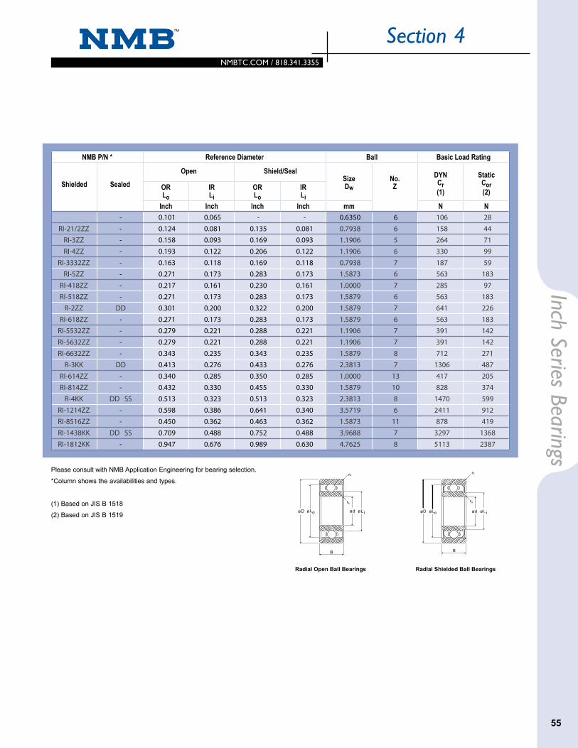
NMBTC.COM / 818.341.3355NMBTC.COM / 818.341.3355
55
Section 4Inch Series Bearings
NMB P/N * Reference Diameter Ball Basic Load Rating
Shielded Sealed Open Shield/Seal
SizeDw
No.Z
DYNCr(1)
StaticCor(2)OR
LoIRLi
ORLo
IRLi
Inch Inch Inch Inch mm N N
Please consult with NMB Application Engineering for bearing selection.
*Column shows the availabilities and types.
(1) Based on JIS B 1518
(2) Based on JIS B 1519
Radial Shielded Ball BearingsRadial Open Ball Bearings
rs
rs
B
Dø Lo d L i ø ø ø ø ø ø ø
B
rs
rs
D Lo d L i
0.0400 1.016 0.1250 3.175 0.0469 1.191 - - 0.003 0.08 RI-2X2 - 0.101 0.065 - - 0.6350 6 106 280.0469 1.191 0.1562 3.967 0.0625 1.588 0.0937 2.380 0.003 0.08 RI-21/2 RI-21/2ZZ - 0.124 0.081 0.135 0.081 0.7938 6 158 440.0550 1.397 0.1875 4.762 0.0781 1.984 0.1094 2.779 0.003 0.08 RI-3 RI-3ZZ - 0.158 0.093 0.169 0.093 1.1906 5 264 710.0781 1.984 0.2500 6.350 0.0937 2.380 0.1406 3.571 0.003 0.08 RI-4 RI-4ZZ - 0.193 0.122 0.206 0.122 1.1906 6 330 990.0937 2.380 0.1875 4.762 0.0625 1.588 0.0937 2.380 0.003 0.08 RI-3332 RI-3332ZZ - 0.163 0.118 0.169 0.118 0.7938 7 187 59
0.3125 7.938 0.1094 2.779 0.1406 3.571 0.003 0.08 RI-5 RI-5ZZ - 0.271 0.173 0.283 0.173 1.5873 6 563 1830.1250 3.175 0.2500 6.350 0.0937 2.380 0.1094 2.779 0.003 0.08 RI-418 RI-418ZZ - 0.217 0.161 0.230 0.161 1.0000 7 285 97
0.3125 7.938 0.1094 2.779 0.1406 3.571 0.003 0.08 RI-518 RI-518ZZ - 0.271 0.173 0.283 0.173 1.5879 6 563 1830.3750 9.525 0.1562 3.967 0.1562 3.967 0.012 0.30 R-2 R-2ZZ DD 0.301 0.200 0.322 0.200 1.5879 7 641 2260.3750 9.525 0.1094 2.779 0.1406 3.571 0.005 0.13 RI-618 RI-618ZZ - 0.271 0.173 0.283 0.173 1.5879 6 563 183
0.1562 3.967 0.3125 7.938 0.1094 2.779 0.1250 3.175 0.003 0.08 RI-5532 RI-5532ZZ - 0.279 0.221 0.288 0.221 1.1906 7 391 1420.1875 4.762 0.3125 7.938 0.1094 2.779 0.1250 3.175 0.003 0.08 RI-5632 RI-5632ZZ - 0.279 0.221 0.288 0.221 1.1906 7 391 142
0.3750 9.525 0.1250 3.175 0.1250 3.175 0.003 0.08 RI-6632 RI-6632ZZ - 0.343 0.235 0.343 0.235 1.5879 8 712 2710.5000 12.700 0.1562 3.967 0.1960 4.978 0.012 0.30 R-3 R-3KK DD 0.413 0.276 0.433 0.276 2.3813 7 1306 487
0.2500 6.350 0.3750 9.525 0.1250 3.175 0.1250 3.175 0.003 0.08 RI-614 RI-614ZZ - 0.340 0.285 0.350 0.285 1.0000 13 417 2050.5000 12.700 0.1250 3.175 0.1875 4.762 0.005 0.13 RI-814 RI-814ZZ - 0.432 0.330 0.455 0.330 1.5879 10 828 3740.6250 15.875 0.1960 4.978 0.1960 4.978 0.012 0.30 R-4 R-4KK DD SS 0.513 0.323 0.513 0.323 2.3813 8 1470 5990.7500 19.050 0.2188 5.558 0.2812 7.142 0.016 0.41 RI-1214 RI-1214ZZ - 0.598 0.386 0.641 0.340 3.5719 6 2411 912
0.3125 7.938 0.5000 12.700 0.1562 3.967 0.1562 3.967 0.005 0.13 RI-8516 RI-8516ZZ - 0.450 0.362 0.463 0.362 1.5873 11 878 4190.3750 9.525 0.8750 22.225 0.2188 5.558 0.2812 7.142 0.016 0.41 RI-1438 RI-1438KK DD SS 0.709 0.488 0.752 0.488 3.9688 7 3297 13680.5000 12.700 1.1250 28.575 0.2500 6.350 0.3125 7.938 0.016 0.41 RI-1812 RI-1812KK - 0.947 0.676 0.989 0.630 4.7625 8 5113 2387
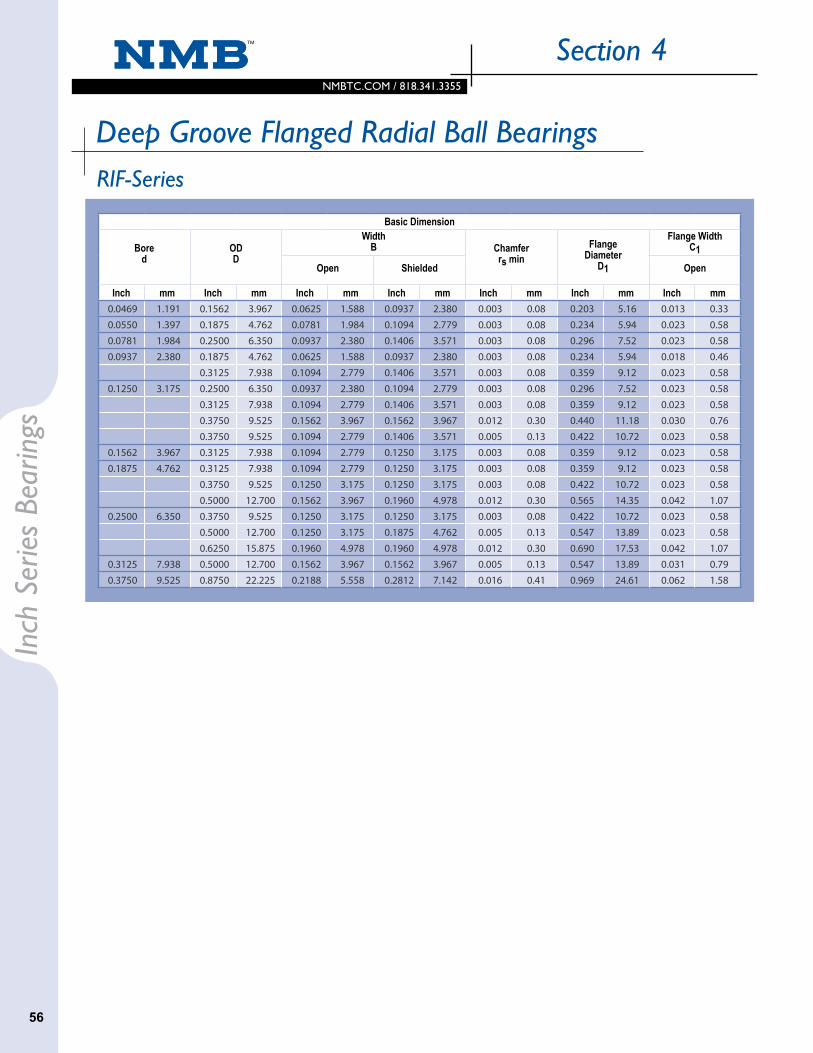
NMBTC.COM / 818.341.3355
Section 4In
ch S
erie
s Be
arin
gs
Basic Dimension
Bored
ODD
Width B Chamfer
rs minFlange
DiameterD1
Flange Width C1
Open Shielded Open
Inch mm Inch mm Inch mm Inch mm Inch mm Inch mm Inch mm
RIF-Series
Deep Groove Flanged Radial Ball Bearings
56
0.0469 1.191 0.1562 3.967 0.0625 1.588 0.0937 2.380 0.003 0.08 0.203 5.16 0.013 0.33 0.031 0.79 RIF-21/2 RIF-21/2ZZ - 0.124 0.081 0.135 0.081 0.7938 6 158 440.0550 1.397 0.1875 4.762 0.0781 1.984 0.1094 2.779 0.003 0.08 0.234 5.94 0.023 0.58 0.031 0.79 RIF-3 RIF-3ZZ - 0.158 0.093 0.169 0.093 1.1906 5 264 710.0781 1.984 0.2500 6.350 0.0937 2.380 0.1406 3.571 0.003 0.08 0.296 7.52 0.023 0.58 0.031 0.79 RIF-4 RIF-4ZZ - 0.193 0.122 0.206 0.122 1.1906 6 330 990.0937 2.380 0.1875 4.762 0.0625 1.588 0.0937 2.380 0.003 0.08 0.234 5.94 0.018 0.46 0.031 0.79 RIF-3332 RIF-3332ZZ - 0.163 0.118 0.169 0.118 0.7938 7 187 59
0.3125 7.938 0.1094 2.779 0.1406 3.571 0.003 0.08 0.359 9.12 0.023 0.58 0.031 0.79 RIF-5 RIF-5ZZ - 0.271 0.173 0.283 0.173 1.5875 6 563 1830.1250 3.175 0.2500 6.350 0.0937 2.380 0.1094 2.779 0.003 0.08 0.296 7.52 0.023 0.58 0.031 0.79 RIF-418 RIF-418ZZ - 0.217 0.161 0.230 0.161 1.0000 7 285 97
0.3125 7.938 0.1094 2.779 0.1406 3.571 0.003 0.08 0.359 9.12 0.023 0.58 0.031 0.79 RIF-518 RIF-518ZZ - 0.271 0.173 0.283 0.173 1.5875 6 563 1830.3750 9.525 0.1562 3.967 0.1562 3.967 0.012 0.30 0.440 11.18 0.030 0.76 0.030 0.76 RF-2 RF-2ZZ - 0.301 0.200 0.322 0.200 1.5875 7 641 2260.3750 9.525 0.1094 2.779 0.1406 3.571 0.005 0.13 0.422 10.72 0.023 0.58 0.031 0.79 RIF-618 RIF-618ZZ - 0.271 0.173 0.283 0.173 1.5875 6 563 183
0.1562 3.967 0.3125 7.938 0.1094 2.779 0.1250 3.175 0.003 0.08 0.359 9.12 0.023 0.58 0.036 0.91 RIF-5532 RIF-5532ZZ - 0.279 0.221 0.288 0.221 1.1906 7 391 1420.1875 4.762 0.3125 7.938 0.1094 2.779 0.1250 3.175 0.003 0.08 0.359 9.12 0.023 0.58 0.036 0.91 RIF-5632 RIF-5632ZZ - 0.279 0.221 0.288 0.221 1.1906 7 391 142
0.3750 9.525 0.1250 3.175 0.1250 3.175 0.003 0.08 0.422 10.72 0.023 0.58 0.031 0.79 RIF-6632 RIF-6632ZZ - 0.343 0.235 0.343 0.235 1.5875 8 712 2710.5000 12.700 0.1562 3.967 0.1960 4.978 0.012 0.30 0.565 14.35 0.042 1.07 0.042 1.07 RF-3 RF-3ZZ - 0.413 0.276 0.435 0.276 2.3813 7 1306 487
0.2500 6.350 0.3750 9.525 0.1250 3.175 0.1250 3.175 0.003 0.08 0.422 10.72 0.023 0.58 0.036 0.91 RIF-614 RIF-614ZZ - 0.340 0.285 0.350 0.285 1.0000 13 417 2050.5000 12.700 0.1250 3.175 0.1875 4.762 0.005 0.13 0.547 13.89 0.023 0.58 0.045 1.14 RIF-814 RIF-814ZZ - 0.432 0.330 0.454 0.330 1.5875 10 828 3740.6250 15.875 0.1960 4.978 0.1960 4.978 0.012 0.30 0.690 17.53 0.042 1.07 0.042 1.07 RF-4 RF-4HH DD 0.513 0.323 0.513 0.323 2.3813 8 1470 599
0.3125 7.938 0.5000 12.700 0.1562 3.967 0.1562 3.967 0.005 0.13 0.547 13.89 0.031 0.79 0.031 0.79 RIF-8516 RIF-8516ZZ - 0.450 0.362 0.463 0.362 1.5875 11 878 4190.3750 9.525 0.8750 22.225 0.2188 5.558 0.2812 7.142 0.016 0.41 0.969 24.61 0.062 1.58 0.062 1.58 RIF-1438 RIF-1438KK DD 0.741 0.520 0.752 0.488 3.9688 7 3297 1368

NMBTC.COM / 818.341.3355NMBTC.COM / 818.341.3355
57
Section 4Inch Series Bearings
Basic Dimension
NMB Part Number * Reference Diameter Ball Basic Load RatingFlange Width
C1Open Shielded Sealed
Open ShieldSeal Size
DwNo.Z
DYNCr(1)
StaticCor(2)Shielded OR
LoIRLi
ORLo
IRLi
Inch mm Inch Inch Inch Inch mm N N
Please consult with NMB Application Engineering for bearing selection.
*Column shows the availabilities and types.
(1) Based on JIS B 1518
(2) Based on JIS B 1519
Radial Flanged Shielded Ball BearingsRadial Flanged Open Ball Bearings
L o d L i DD1
r
r
s
s
B
C1 C1
B
ø D1øø ø ø ø DLo Lid
rs
rs
ø ø ø ø
0.0469 1.191 0.1562 3.967 0.0625 1.588 0.0937 2.380 0.003 0.08 0.203 5.16 0.013 0.33 0.031 0.79 RIF-21/2 RIF-21/2ZZ - 0.124 0.081 0.135 0.081 0.7938 6 158 440.0550 1.397 0.1875 4.762 0.0781 1.984 0.1094 2.779 0.003 0.08 0.234 5.94 0.023 0.58 0.031 0.79 RIF-3 RIF-3ZZ - 0.158 0.093 0.169 0.093 1.1906 5 264 710.0781 1.984 0.2500 6.350 0.0937 2.380 0.1406 3.571 0.003 0.08 0.296 7.52 0.023 0.58 0.031 0.79 RIF-4 RIF-4ZZ - 0.193 0.122 0.206 0.122 1.1906 6 330 990.0937 2.380 0.1875 4.762 0.0625 1.588 0.0937 2.380 0.003 0.08 0.234 5.94 0.018 0.46 0.031 0.79 RIF-3332 RIF-3332ZZ - 0.163 0.118 0.169 0.118 0.7938 7 187 59
0.3125 7.938 0.1094 2.779 0.1406 3.571 0.003 0.08 0.359 9.12 0.023 0.58 0.031 0.79 RIF-5 RIF-5ZZ - 0.271 0.173 0.283 0.173 1.5875 6 563 1830.1250 3.175 0.2500 6.350 0.0937 2.380 0.1094 2.779 0.003 0.08 0.296 7.52 0.023 0.58 0.031 0.79 RIF-418 RIF-418ZZ - 0.217 0.161 0.230 0.161 1.0000 7 285 97
0.3125 7.938 0.1094 2.779 0.1406 3.571 0.003 0.08 0.359 9.12 0.023 0.58 0.031 0.79 RIF-518 RIF-518ZZ - 0.271 0.173 0.283 0.173 1.5875 6 563 1830.3750 9.525 0.1562 3.967 0.1562 3.967 0.012 0.30 0.440 11.18 0.030 0.76 0.030 0.76 RF-2 RF-2ZZ - 0.301 0.200 0.322 0.200 1.5875 7 641 2260.3750 9.525 0.1094 2.779 0.1406 3.571 0.005 0.13 0.422 10.72 0.023 0.58 0.031 0.79 RIF-618 RIF-618ZZ - 0.271 0.173 0.283 0.173 1.5875 6 563 183
0.1562 3.967 0.3125 7.938 0.1094 2.779 0.1250 3.175 0.003 0.08 0.359 9.12 0.023 0.58 0.036 0.91 RIF-5532 RIF-5532ZZ - 0.279 0.221 0.288 0.221 1.1906 7 391 1420.1875 4.762 0.3125 7.938 0.1094 2.779 0.1250 3.175 0.003 0.08 0.359 9.12 0.023 0.58 0.036 0.91 RIF-5632 RIF-5632ZZ - 0.279 0.221 0.288 0.221 1.1906 7 391 142
0.3750 9.525 0.1250 3.175 0.1250 3.175 0.003 0.08 0.422 10.72 0.023 0.58 0.031 0.79 RIF-6632 RIF-6632ZZ - 0.343 0.235 0.343 0.235 1.5875 8 712 2710.5000 12.700 0.1562 3.967 0.1960 4.978 0.012 0.30 0.565 14.35 0.042 1.07 0.042 1.07 RF-3 RF-3ZZ - 0.413 0.276 0.435 0.276 2.3813 7 1306 487
0.2500 6.350 0.3750 9.525 0.1250 3.175 0.1250 3.175 0.003 0.08 0.422 10.72 0.023 0.58 0.036 0.91 RIF-614 RIF-614ZZ - 0.340 0.285 0.350 0.285 1.0000 13 417 2050.5000 12.700 0.1250 3.175 0.1875 4.762 0.005 0.13 0.547 13.89 0.023 0.58 0.045 1.14 RIF-814 RIF-814ZZ - 0.432 0.330 0.454 0.330 1.5875 10 828 3740.6250 15.875 0.1960 4.978 0.1960 4.978 0.012 0.30 0.690 17.53 0.042 1.07 0.042 1.07 RF-4 RF-4HH DD 0.513 0.323 0.513 0.323 2.3813 8 1470 599
0.3125 7.938 0.5000 12.700 0.1562 3.967 0.1562 3.967 0.005 0.13 0.547 13.89 0.031 0.79 0.031 0.79 RIF-8516 RIF-8516ZZ - 0.450 0.362 0.463 0.362 1.5875 11 878 4190.3750 9.525 0.8750 22.225 0.2188 5.558 0.2812 7.142 0.016 0.41 0.969 24.61 0.062 1.58 0.062 1.58 RIF-1438 RIF-1438KK DD 0.741 0.520 0.752 0.488 3.9688 7 3297 1368

2.1
NMBTC.COM / 818.341.3355
Bear
ing
Dam
age
&
Coun
term
easu
reSection 5
58
Bearing Damage and CountermeasureIf equipment assembled with ball bearings isn’t working correctly, or if the ball bearings themselves were damaged, the root causes of the failure can be determined by looking at the condition of the bearings. Better performance and longer life can be achieved by preventing the damage. Some common failure modes and preventive methods are described below.
Failure Modes Major Causes Countermeasure
Rotation
Unable to rotate
or hard to rotate
Grease Type and Amount Review grease selection and improve drive system (motor).
Parts Rubbing Review process and design.
Grease Degradation (Particles) Review lubricants. Review types and increase fill amount.
Flaking (caused by Metal Fatigue) Review load and rotational conditions. Increase bearing size.
Noise
Resonance of Components Review dimensions (thickness) and materials of the components.
Continuous Noise
Brinell Damage on the RacewaysReview handling and installation of bearings.
Review transportation process of the applications. (Check for excessive load and shock loads)
Contamination Dents on the Raceways
Select a sealed type bearing. Review installation environment.
Intermittent Noise
Insufficient Preload Review preload amount based on the load and rotation conditions.
Contamination Dents Select a sealed type bearing. Review installation environment.
Damage on Balls Review process and installation environment. (Contamination, and excessive loads).
Vibration
Excessive Internal Clearance Decrease internal clearance.
Improper Preload Review preload amount based on the load and rotation conditions.
Misalignment Review process, dimensional tolerance, cleanliness of the components.
Deformation of the Raceways Review precision (roundness) of the shafts or housings. Review adhesive and its process.
TemperatureIncrease
Improper Grease Type and Amount Review grease and fill amount.
Excessive Load Review load carrying capability and fits.
Grease Leak
Grease Type and Amount Review grease and fill amount.
Improper Selection of Shield and Seal Review seal or shield type.
Plastic Damage
(Cracking)
Chemical Attack Review lubricant types. Reduce stress to the plastic or change the material type.
Excessive Interference Review fits.
Weld Line Review molding conditions and gate position.
Abnormal Conditions

2.1
NMBTC.COM / 818.341.3355NMBTC.COM / 818.341.3355
59
Bearing Dam
age &
Countermeasure
Section 5
Damage Types
Damage Conditions Major Causes Countermeasure
Flaking (by Metal Fatigue) Excessive Load Review bearing size and load conditions.
Improper Installation Review dimensions and precision of shafts and housings.
Improper Lubrication Review lubricant type and fill amount.
Dents (Brinelling) Excessive Load Applied
During AssemblyCareful handling.
Shock Loads Applied During Handling
Careful handling.
Rough SurfaceContamination Review process and
installation environments.
Improper Lubrication Review lubricant type and fill amount.
Creeping
Insufficient Interference Review fits and Interference.
Electric Corrosion (Arcing)
Surface Fluting Caused by electricity passing through bearings.
Insulate and install ground wire.

NMBTC.COM / 818.341.3355
Section 6
Miniature and Instrument Ball Bearings Inner Ring
Tolerances
Ring Width
Outer Ring
Characteristic Configuration Size Range ABEC 1 ABEC 3 ABEC 5 ABEC 7
Mean O.D. Tolerance Limits All 0-18mm +.0000 +.0000 +.0000 +.0000 (0-.709) -.0003 -.0003 -.0002 -.0002 All over 18-30mm +.00000 +.0000 +.0000 +.0000 (.709-1.1811) -.00035 -.0003 -.0002 -.0002
Radial Runout All 0-18mm .0006 .0004 .0002 .00015 All over 18-30mm .0006 .0004 .0002 .00015Width Variation All 0-30mm — — .0002 .00010O.D. Runout with Face All 0-30mm — — .0003 .00015Race Runout with Face Plain 0-18mm — — .0003 .00020 Plain over 18-30mm — — .0003 .00020 Flanged 0-30mm — — .0003 .00030
Flange Width Tolerance Limits — — — +.0000 +.0000 +.0000 — — — -.0020 -.0020 -.0020
Flange Diameter — — — +.0050 +.0000 +.0000Tolerance Limits — — — -.0020 -.0010 -.0010
Characteristic ABEC 1 ABEC 3 ABEC 5 ABEC 7
Width Tolerance +.000 +.000 +.000 +.000 -.005 -.005 -.001 -.001
Characteristic ABEC 1 ABEC 3 ABEC 5 ABEC 7
Mean Bore Tolerance Limits +.0000 +.0000 +.0000 +.0000 -.0003 -.0002 -.0002 -.0002
Radial Runout .0003 (1) .0002 (1) .00015 .0001Width Variation — — .00020 .0001
Bore Runout with Face — — .00030 .0001
Race Runout with Face — — .00030 .0001
(1) Add .0001 to the tolerance if bore size is over 10mm (.3937 inch).
Appe
ndix
60

NMBTC.COM / 818.341.3355NMBTC.COM / 818.341.3355
61
Section 6
-79-73-68-62-57
-51-46-40-34-29
-23-17.7-17.2-16.6-16.1
-15.5-15.0-14.4-13.9-13.3
-12.7-12.2-6.6-1.14.4
9.915.621.026.832.1
-110-100-90-80-70
-60-50-40-30-20
-100123
45678
910203040
5060708090
-166-148-130-112-94
-76-58-40-22-4
1432
33.835.637.4
39.241.042.844.646.4
48.250.068.086.0
104.0
122.0140.0158.0176.0194.0
37.743495460
6571768388
9399
104110115
121127132138143
149154160165171
177182188193199
100110120130140
150160170180190
200210220230240
250260270280290
300310320330340
350360370380390
212230248266284
302320338356374
392410428446464
482500518536554
572590608626644
662680698716734
204210215221226
232238243249254
260265271276282
288293299304310
315321326332338
343349354360365
400410420430440
450460470480490
500510520530540
550560570580590
600610620630640
650660670680690
752770788806824
842860878896914
932950968986
1004
10221040105810761094
11121130114811661184
12021220123812561274
371376382387393
565571576582587
593598604609615
620626631637642
648653659664670
675681686692697
700 710 720 730 740
10501060107010801090
11001110112011301140
11501160117011801190
12001210122012301240
12501260127012801290
12921310132813461364
19221940195819761994
20122030204820662084
21022120213821562174
21922210222822462264
22822300231823362354
°C °C/°F °F °C °C/°F °F °C °C/°F °F °C °C/°F °F
Appendix
61
Temperature Conversion TableThe numbers in the center column refer to the temperatures either in Celsius or Fahrenheit which need conversion to the other scale. When converting from Fahrenheit to Celsius, the equivalent temperature will be found to the left of the center column. If converting from Celsius to Fahrenheit the answer will be found to the right.

NMBTC.COM / 818.341.3355
Section 6Ap
pend
ix
1/64
1/32
3/64
1/16
5/64
3/32
7/64
1/8
9/645/32
11/643/16
13/64
7/3215/64
1/417/64
9/32
0.01560.02500.03120.03940.04000.04690.04720.05500.05910.06250.07090.07810.07870.09060.09370.09840.10000.10240.10940.11000.11020.11810.12500.12560.13780.14060.15620.15750.17190.18750.18920.19690.20310.21650.21870.23440.23620.25000.26560.27560.2812
0.39690.63500.79371.00001.01601.19061.20001.39701.50001.58751.80001.98442.00002.30122.38122.50002.54002.60002.77812.79402.80003.00003.17503.19023.50003.57193.96874.00004.36564.76254.80575.00005.15945.49915.55625.95316.00006.35006.74697.00007.1437
19/645/16
21/6411/32
23/643/825/64
13/32
27/64
7/1629/64
15/32
31/641/2
33/6417/3235/64
9/1637/64
19/3239/645/8
41/64
21/32
43/64
0.28830.29690.31250.31500.32810.34370.35430.35940.37500.39060.39370.40620.41000.42190.42500.43310.43750.45310.46000.46870.47240.48440.50000.51180.51560.53120.54690.55120.56250.57810.59060.59370.60940.62500.62990.64060.65000.65620.66200.66930.6719
7.32287.54067.93758.00008.33448.73129.00009.12819.52509.921310.000010.318710.414010.715610.795011.000011.112511.509411.684011.906212.000012.303112.700013.000013.096813.493713.890614.000014.287514.684415.000015.081215.478115.875016.000016.271916.510016.668716.814817.000017.0656
11/1645/64
23/3247/64
3/449/64
25/32
51/6413/16
53/6427/3255/64
7/857/64
29/3259/6415/16
61/6431/32
63/64
1-1/16
1-1/8
1-3/161-1/41-1/2
0.68750.70310.70870.71870.73440.74350.74800.75000.76560.77170.78120.78740.79690.81250.82680.82810.84370.85940.86610.87500.89060.90550.90620.92190.93750.94490.95310.96870.98430.98441.00001.02361.04151.04801.06251.06301.10251.12501.14171.18121.18751.25001.5000
17.462517.859418.000018.256218.653218.884919.000019.050019.446919.601219.843320.000020.240220.637521.000021.034421.431221.828122.000022.225022.621923.000023.018723.415623.812524.000024.209424.606225.000025.003125.400026.000026.454126.619226.987527.000028.000028.575029.000030.000030.162531.750038.1000
Fraction Inch MM Fraction Inch MM Fraction Inch MM
Metric Conversion Table
62

Additional Products From NMB Small Motors
NMB’s small motor products include a line of hybrid and permanent magnet stepper motors, as well as NMB’s brush and brushless DC motors. The brush DC motor line is ideal for applications that require small size and excellent power output. The brushless DC line is perfect for applications where
the environment is sensitive to interference, battery powered equipment and clean room. Standard NMB hybrid and permanent magnet stepper motors are available, as well as many customizable features for your unique application.
For more information on our motor products, e-mail us at: [email protected]
Cooling Fans
NMB offers a comprehensive line of more than 100 axial fans ranging in size from 25mm to 173mm. DC & AC Axial fans and blowers are designed to solve thermal management problems for our OEM customers. Producing over 100 million fans per year, NMB’s focus is on total thermal management solutions. With three engineering centers for cooling fan design, our own vertical manufacturing process and a dedicated sales force we are committed to providing a quality solution for your cooling needs.
For more information on our cooling fans, e-mail us at: [email protected]
Mechanical Bearing Assemblies
NMB’s Miniature Precision Ball Bearings are the first component of a highly successful design of a mechanical bearing assembly. Machined components such as magnets, gears, molded and machine plastic parts, die cast parts and special materials are
designed and manufactured to work precisely with NMB precision ball bearings. Complex mechanical bearing assemblies are custom made to your design specifications, and are ideal for medical, office automation, and currency machines, as well as factory and lab automation applications.
For more information on our mechanical assembly products, e-mail us at: [email protected]
Fan Trays
NMB’s extensive selection of AC and DC cooling fans, as well as the latest range of high efficiency motorized impellers are your turn-key solution for your custom fan tray designs. NMB’s fan tray product offerings include single or multiple devices, redundant and single-point of failure proof design, intelligent and self regulated control functions, two way communication with system for remote access and wide voltage range design.
For more information on our custom Fan Trays e-mail us at: [email protected]
North America
Corporate Headquarters
9730 Independence Avenue
Chatsworth, CA 91311
P: 818-341-3355, F: 818-341-8207
www.nmbtc.com
International Sales Offices
Sao Paulo, Brazil
Shanghai, China
Bracknell, England
Baillet en France, France
Langen, Germany
Kowloon, Hong Kong
Haryana, India
Milan, Italy
Tokyo, Japan
Kuala Lumpur, Malaysia
Manila, Philippines
Singapore
Seoul, South Korea
Taipei, Taiwan
Bangkok, Thailand
Hanoi, Vietnam
4.2015
Represented by:
NMB Technologies Corporation
Barracuda
Typewritten Text
Barracuda
Typewritten Text