Beamline CDR Template · 2010-04-15 · CDR Conceptual Design Report CFD Conventional Facilities...
18
LT-XFD_CDR_BLI-00120 NSLS-II Project CONCEPTUAL DESIGN REPORT for the BEAMLINES INFRASTRUCTURE at NSLS-II final draft Sep 2009
Transcript of Beamline CDR Template · 2010-04-15 · CDR Conceptual Design Report CFD Conventional Facilities...

LT-XFD_CDR_BLI-00120
NSLS-II Project CONCEPTUAL DESIGN REPORT for the
BEAMLINES INFRASTRUCTURE at NSLS-II
final draft Sep 2009

NSLS-II Project, Brookhaven National Laboratory
ii September 2009
Intentionally blank.

Conceptual Design Report for the Beamlines Infrastructure at NSLS-II
September 2009 iii
Approvals and Reviewers
Compiled by Signature Date
Andrew Broadbent, Beamlines Manager, NSLS-II
Reviewers
Nicholas Gmür, ESH Coordinator, NSLS-II
Sushil Sharma, Mechanical Engineering Group Leader, NSLS-II
Approvals
Qun Shen, XFD Director, NSLS-II
Document Updates The Conceptual Design Report for the Beamlines Infrastructure at NSLS-II is a controlled document, revised under change control.
Version No. Date Authorized by Changes made
A 9/22/09 A. Broadbent Initial draft
1 9/30/09 final draft submitted

NSLS-II Project, Brookhaven National Laboratory
iv September 2009
Intentionally blank.
Conceptual Design Report for the Beamlines Infrastructure at NSLS-II
September 2009 v
Contents
1. INTRODUCTION ...............................................................................................................................................1
2. SAFETY ...........................................................................................................................................................1
2.1 Safety Review Process ......................................................................................................................1
2.2 Radiation Shielding ............................................................................................................................1
3. CONVENTIONAL FACILITIES INTERFACES..................................................................................................2
3.1 Experimental Floor and Building ...................................................................................................2
3.2 Beamline Locations ............................................................................................................................2
3.3 Utilities ................................................................................................................................................5
3.3.1 General .................................................................................................................................5
3.3.2 UPS systems.........................................................................................................................5
3.4 Laboratory Office Buildings (LOBs)....................................................................................................5
3.5 Hard X-ray Nanoprobe Remote Station .............................................................................................8
3.6 Construction Phasing Plan. ................................................................................................................9
4. ACCELERATOR SYSTEMS DIVISION INTERFACES ..................................................................................11
4.1 Insertion Devices..............................................................................................................................11
4.2 Front Ends........................................................................................................................................11
NSLS-II Project, Brookhaven National Laboratory
vi September 2009
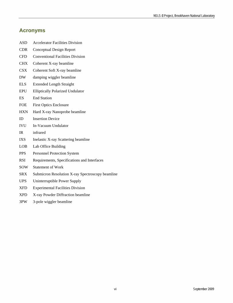
Acronyms
ASD Accelerator Facilities Division
CDR Conceptual Design Report
CFD Conventional Facilities Division
CHX Coherent X-ray beamline
CSX Coherent Soft X-ray beamline
DW damping wiggler beamline
ELS Extended Length Straight
EPU Elliptically Polarized Undulator
ES End Station
FOE First Optics Enclosure
HXN Hard X-ray Nanoprobe beamline
ID Insertion Device
IVU In-Vacuum Undulator
IR infrared
IXS Inelastic X-ray Scattering beamline
LOB Lab Office Building
PPS Personnel Protection System
RSI Requirements, Specifications and Interfaces
SOW Statement of Work
SRX Submicron Resolution X-ray Spectroscopy beamline
UPS Uninterruptible Power Supply
XFD Experimental Facilities Division
XPD X-ray Powder Diffraction beamline
3PW 3-pole wiggler beamline
Conceptual Design Report for the Beamlines Infrastructure at NSLS-II
September 2009 1
1. INTRODUCTION This document is written as an accompaniment to the Conceptual Design Reports for each of the six NSLS-II project beamlines. It will describe the infrastructure necessary to support the beamlines, including a number of items outside the formal Experimental Facilities Division (XFD) responsibility, such as insertion devices and front ends (ASD responsibility) and the experimental floor and utility interface points (CFD responsibility). This document also covers the x-ray shielding hutches and the local utilities provisions.
2. SAFETY
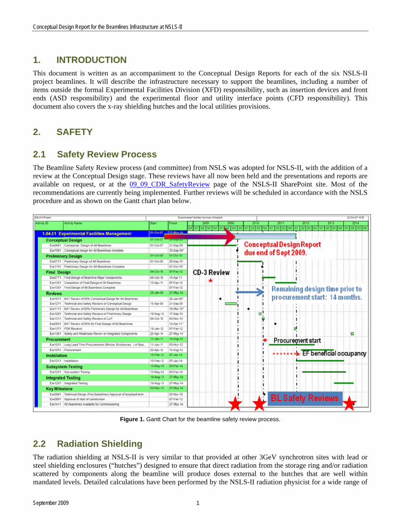
2.1 Safety Review Process The Beamline Safety Review process (and committee) from NSLS was adopted for NSLS-II, with the addition of a review at the Conceptual Design stage. These reviews have all now been held and the presentations and reports are available on request, or at the 09_09_CDR_SafetyReview page of the NSLS-II SharePoint site. Most of the recommendations are currently being implemented. Further reviews will be scheduled in accordance with the NSLS procedure and as shown on the Gantt chart plan below.
Figure 1. Gantt Chart for the beamline safety review process.
2.2 Radiation Shielding The radiation shielding at NSLS-II is very similar to that provided at other 3GeV synchrotron sites with lead or steel shielding enclosures (“hutches”) designed to ensure that direct radiation from the storage ring and/or radiation scattered by components along the beamline will produce doses external to the hutches that are well within mandated levels. Detailed calculations have been performed by the NSLS-II radiation physicist for a wide range of

NSLS-II Project, Brookhaven National Laboratory
2 September 2009
generic “standard” configurations, and these calculations will be continued to cover specific beamline situations not covered by the standard configurations. A review committee will evaluate all beamline and front end shielding designs. A document entitled “Shielding Guidelines for Beamlines” has been written and is available on request. For many standard beamline configurations, lead hutches will be required for First Optics Enclosures (FOEs), with steel hutches used for end stations. Notable exceptions are the requirement for lead hutches on the end stations of damping wiggler beamlines, and no lead requirement for experimental hutches on soft x-ray beamlines; this is in line with practice elsewhere. A detailed Statement of Work (SOW) has been written for hutch procurement; this is available on request. This SOW will be used to ensure standardization of labyrinths, guillotines, doors, and Personnel Protection System (PPS) interfaces. It is anticipated that a specification sheet and drawing will accompany the general SOW for each hutch to be procured; the specification sheets are relatively short and an example is provided in the Statement of Work.
3. CONVENTIONAL FACILITIES INTERFACES
3.1 Experimental Floor and Building The general environment for the beamlines is defined in the document “Experimental Facilities Requirements, Specifications and Interfaces for the Ring Building and Experimental Floor.” This discusses such important environmental factors as the facility temperature, temperature and humidity stability, as well as ambient noise, vibration, lighting, fire safety, emergency egress and infrastructure, beamline floor territory, accommodation of long beamlines, etc. The floor layout, including the walkway boundaries between beamlines, is shown in Figure 2. This layout slightly favors insertion device (ID) floor space over floor space for bending magnets (BMs) and three-pole wiggler (3PW) magnets, while allowing access to the front-end access doors in the ratchet wall (for ID front ends only). Note 1 on the drawing refers to emergency access “duck-unders.” These are discussed in a Safety Committee memo dated 3 April 2008.
3.2 Beamline Locations The beamline locations need to be finalized by the end of March 2010 to enable advanced sequencing of the construction activities to continue. Table 1 documents the absolute beamline location constraints and some of the preferences for beamline locations. Prior assumptions Project damping wigglers require three-fold symmetry and are installed on the “8’s” (i.e., straights 8, 18, and 28). Straights reserved for future damping wigglers, also with three-fold symmetry, are installed on the “6’s” (i.e., straights 6, 16, and 26).

Conc
September 2009 3
eptual Design Report for the Beamlines Infrastructure at NSLS-II
Figure 2. Floor layout.

NSLS-II Project, Brookhaven National Laboratory
4 September 2009
Beamline Straight Extended experimental floor? Long beamline? Location requirements Options Location preferences Preference
IXS Hi-beta
Y N Non damping wiggler straight
4, 10, 12
ELS capability (at least with shorter adjacent straights, even if not with three-fold symmetry).
10-ID
HXN Low-beta Not required Y Not adjacent to LOB loading docks.
27, 3, 9
Optimized location with low vibration levels.
3-ID
CHX Low-beta Y N Extended experimental floor to allow emergency duck-under between FOE and ES.
5, 11, 17, 23, 29
None 5-ID
CSX Low-beta Y N Located away from sources of draughts (exposed optics and end station).
5, 11, 17, 23, 29
Straight 23 is between RF straights and therefore likely to have convenient “parking” space for additional end stations.
23-ID
SRX Low-beta, canted N N Does not require extended experimental floor.
Ideally near an IR beamline position. Close to bio village.
21-ID
XPD Hi-beta
Y N DW source
18, 28
At beneficial occupancy, there is a long duration between the floor at straight 28 and straight 18 being available.
28-ID
ELS = Extended Length Straight (a future concept to give a single very long straight at the expanse of adjacent straight lengths)
Table 1: Absolute Beamline Location Constraints and Some Preferences.
ES = end station FOE = first optics enclosure ID = insertion device LOB = lab office building

NSLS-II Project, Brookhaven National Laboratory
5 September 2009
3.3 Utilities
3.3.1 General The strategy with the utility distribution system has been to define a set of convenient interface points for a standardized set of beamline utilities. These interface points will generally serve one or two beamlines. The requirements, specifications, and interfaces (RSI) document entitled “Requirements, Specifications and Interfaces for the Experimental Facilities Utilities” (available on request) defines the utility interfaces and provides information on the estimated utility loads. This document also provides information on how the utilities are to be distributed along the beamline to the various pieces of equipment.
3.3.2 UPS systems Review committees in the past have commented on the need for, and made recommendations relating to, the inclusion of uninterruptable power supply (UPS) systems. Considerable time has been spent working with the ASD staff and local agents for the large UPS system manufacturers to define systems suitable for the beamlines. The conclusion is that the UPS systems should have a reasonable “whole of life” cost, remote monitoring, high reliability, and low environmental impact while retaining some compatibility with the distributed system proposed for the storage ring controls and data-archiver. Two discussion papers recommend distributed systems and then further analyze the life cycle costs and options. See “Beamline UPS Systems Discussion Sept09.doc” and “UPS discussion document.doc,” available on request. In summary, the reports recommend small, distributed UPS systems sized to provide adequate power for a single beamline. The electrical distribution costs alone dictate against sharing UPS systems over several beamlines, and distributed systems minimize issues of earthing, electrical noise propagation, and safety concerns.
3.4 Laboratory Office Buildings (LOBs) The laboratory office buildings are on an accelerated schedule, with the 100% design submission due from the architects at the end of September 2009. Considerable interaction with representatives of the user community has occurred to ensure that the standard building footprint planned for all five LOBs is suitable for all communities, including the biology community, who are expected to have a different configuration within the LOB to allow for specific laboratory requirements (including cold rooms, etc.). The RSI document for the LOBs is available on request. This document defines the number of offices, labs, kitchen areas, etc. within the building; states the intended lab and workshop purposes; and defines the utilities needed by users. A color-coded drawing of the LOB is provided on the following page. Please note:
The chamfered left-hand end is to allow long beamlines to pass the building.
Scientists’ offices (green) are around the perimeter.
A wide central atrium links the entrance door with the main door to the Experimental Floor.
Seating for students and users is perpendicular to the central atrium. Both of these areas have clerestory windows to give good natural light with minimal solar gain.
A double conference room can be merged to form a single large conference room near the main entrance. There is also another conference room close to the Experimental Floor.
There is an area for administrative staff (yellow).
Ten workshops and laboratories plus a small machine shop (blue) are provided.
The shipping and receiving area with stores space is adjacent to the Experimental Floor at the right-hand end of the LOB.
Images of the LOB are shown overleaf, provided by HDR (Architects) on 10 Sept 2009, 3 weeks prior to 100% design submittal.

ect, Brookhaven National Laboratory
6 September 2009
Figure 3. Drawing of the LOB floor plan.
NSLS-II Proj

Conceptual Design Report for the Beamlines Infrastructure at NSLS-II
7 September 2009
Figure 4. Views of the LOB interior.
Figure 5. The central atrium of the LOB.

NSLS-II Project, Brookhaven National Laboratory
8 September 2009
3.5 Hard X-ray Nanoprobe Remote Station The remote station for the nanoprobe is something of a misnomer, since it is located very close to the LOB. Earlier versions of the building were located further away from the storage ring building; the move closer was made for scientific/optics reasons, but there are some engineering benefits including utility connections directly from the LOB and reduced wind loading on the structure. Very considerable steps have been taken to minimize vibration levels, including holding a workshop at BNL inviting many experts from on site and across the United States, using the services of the CFD vibration expert (Nick Simos), who made many measurements and models to predict the likely impact of traffic, site noise, ocean waves, NSLS-II services, and the filtering effect of the concrete slabs. A sketch of the proposed building is shown below. Some key points are as follows:
The building should be completely separate from the storage ring building with no interconnected columns or girders.
The separation is critical; it will be thick concrete with isolating foam used between the ring building and the satellite building.
The building will be fully concrete construction based on the “house within a house” concept. The inner “house” is the concrete hutch (8" thick walls – 4" walls required for radiation shielding, doubled to avoid porosity problems). The hutch doors will be steel and the personnel door will incorporate an airlock. (emergency egress requirements are currently being reviewed with BNL staff).
Connections from the satellite building to the ring building (e.g., for personnel access and for the beampipe) will be done in a lightweight, insulated fabricated steel (or similar) construction material.
Figure 6. Sketch of the proposed HXN remote station.

Conc
eptual Design Report for the Beamlines Infrastructure at NSLS-II
9 September 2009
3.6 Construction Phasing Plan One key interface during the facility construction will be the coordination with CFD and ASD activities. Upon beneficial occupancy of each phase, the experimental floor will be used as a staging area for magnet girders and power supplies before they are installed in the storage ring and on the tunnel roof, respectively. Some advanced planning has occurred and this will be further developed over the coming year. The key points are as follows:
XFD will try to remain out of the way of ASD installation activities.
Girders will enter the storage ring building (and be moved onto the experimental floor) through the main entrance, which will not be completed until the whole building is complete. The concrete pad for the entrance lobby will be used for offloading girders from trucks before they are wheeled into the building through a temporary opening. The girders will be towed around the facility on the 10-ft wide walkway (and not via the bypass corridors).
Current schedules call for hutch installation to start after beneficial occupancy of the whole ring building (a very conservative assumption); we now anticipate gaining earlier access to the floor, in sections, after each individual phase is complete and the ASD activity finishes.
The first activity after ASD work is completed would be floor painting, prior to hutch erection. The phasing plan for construction of the synchrotron building, agreed with Torcon, is shown in Figure 7 on the following page.

NSLS-II Project, Brookhaven National Laboratory
Figure 7. Phasing plan for construction of the synchrotron building.
10 September 2009

NSLS-II Project, Brookhaven National Laboratory
11 September 2009
4. ACCELERATOR SYSTEMS DIVISION INTERFACES
4.1 Insertion Devices A significant amount of work has been done over the past year to further define and refine the insertion devices for the NSLS-II project beamlines. The standard in-vacuum undulator (IVU) remains the 3m long U20 device; however, a number of variants are envisaged to optimally meet the scientific requirements of the beamlines while maintaining performance of the storage ring. The elliptically polarized undulator (EPU) has also been optimized to meet the scientific requirements for energy range. The damping wiggler remains the standard device with a 90mm period.
In-vacuum undulators IXS Beamline U22 6m long (probably 2 x 3m devices)
HXN Beamline U20 3m long – standard device
CHX Beamline U20 3m long – standard device
SRX Beamline U21 1.5m long (note; this is one device of a canted pair)
Other insertion devices CSX Beamline EPU 49 2m long
XPD Beamline DW90 7m long (standard, 2 x 3.5m sections, uncanted). The Insertion Devices for NSLS-II are described in a document discussing the NSLS-II radiation sources (actually a recent update of Chapter 5 of the NSLS-II Conceptual Design Report), this is available on request. A paper presented by Chubar et al. at the SRI 09 conference, “Parametric Optimization of Undulators for NSLS-II Project Beamlines,” provides further information and detail about the detailed optimization procedure employed, (this is also available on request).
4.2 Front Ends The front ends for the project beamlines are currently in the design phase. Currently, detailed designs exist for standard hard and soft x-ray undulator beamline front ends, and work is proceeding on the damping wiggler and canted beamline front ends. The design work has included detailed value engineering studies and the building of prototypes, which have been subjected to life cycle testing (e.g., shutter bellows to >800k cycles). There have also been several formal reviews; this work will continue and it is anticipated that a fully working prototype will be constructed shortly. A presentation, “Front Ends for NSLS-II” by Lewis Doom, which describes the current status of the front end program, was presented to the BNL Light Sources Beamline Safety Review Committee on 24 August 2009. That presentation and the committee report are available on request. The standard Front end is shown overleaf.

NSLS-II Project, Brookhaven National Laboratory
Figure 8. Standard Front End layout.
12 September 2009