BDC01MR-1 - New Jersey€¦ · BDC01MR-1 8/31/01 NJDOT Design Manual - Roadway 14-1 Traffic Control...
39
BDC01MR-1 8/31/01 NJDOT Design Manual - Roadway 14-1 Traffic Control Plans and Details SECTION 14 GUIDELINES FOR TRAFFIC CONTROL PLANS AND DETAILS 14-01 INTRODUCTION This Section along with the Traffic Control Details presented in the Standard Roadway Construction / Traffic Control / Bridge Construction Details and the Traffic Control Plans and Traffic Control and Staging Plans presented in the Sample Plans were prepared to provide designers with general guidelines and examples of minimum desirable applications for typical situations requiring lane closures and/or lane shifts. This information may be used along with the current Manual on Uniform Traffic Control Devices (MUTCD) Part VI to prepare more detailed and site specific Traffic Control Plans that will enable the contractor to construct the project with adequate consideration of safety to motorists, pedestrians and construction workers. Designers should not refer to or use the Traffic Control Details without proper evaluation of the specific site constraints and construction procedures required to construct the project. Traffic Control Plans should be prepared in accordance with the current Sample Plans. The Traffic Control and Staging methods established for each project should be consistent with the general provisions of this Section and should be based on good safety practices, engineering judgement, the speed and volume of traffic, the duration of the operation, the exposure to potential hazards, sight distance constraints and the physical features of the roadway including horizontal alignment, vertical alignment and the presence of intersections and driveways. 14-02 GENERAL The first two sheets of the Traffic Control Plans should be Standard Traffic Control Detail sheets TCD-1A and TCD-1B as appropriately modified for individual project needs. These sheets contain a standard legend of typical traffic control devices, general traffic control notes, an escape ramp detail, a typical section for placement of construction barrier, a table showing recommended spacing of the channeling devices and a table showing recommended sight distances to the beginning of channelizing tapers. The legend and general traffic control notes should be reviewed and modified to include other project specific symbols and notes as necessary for each project. The standard sheets can also be modified to include other project specific information necessary to adequately address traffic control needs. Where required for clarification, sectional views showing the placement of traffic control devices adjacent to the traveled way and the work site should be provided.
-
Upload
truongphuc -
Category
Documents
-
view
213 -
download
1
Transcript of BDC01MR-1 - New Jersey€¦ · BDC01MR-1 8/31/01 NJDOT Design Manual - Roadway 14-1 Traffic Control...

BDC01MR-1 8/31/01
NJDOT Design Manual - Roadway 14-1
Traffic Control Plans and Details
SECTION 14
GUIDELINES FOR TRAFFIC CONTROL PLANS AND DETAILS
14-01 INTRODUCTION
This Section along with the Traffic Control Details presented in the StandardRoadway Construction / Traffic Control / Bridge Construction Details andthe Traffic Control Plans and Traffic Control and Staging Plans presented in theSample Plans were prepared to provide designers with general guidelines andexamples of minimum desirable applications for typical situations requiring laneclosures and/or lane shifts. This information may be used along with the currentManual on Uniform Traffic Control Devices (MUTCD) Part VI to prepare moredetailed and site specific Traffic Control Plans that will enable the contractor toconstruct the project with adequate consideration of safety to motorists, pedestriansand construction workers.
Designers should not refer to or use the Traffic Control Details without properevaluation of the specific site constraints and construction procedures required toconstruct the project. Traffic Control Plans should be prepared in accordance with thecurrent Sample Plans. The Traffic Control and Staging methods established foreach project should be consistent with the general provisions of this Section andshould be based on good safety practices, engineering judgement, the speed andvolume of traffic, the duration of the operation, the exposure to potential hazards, sightdistance constraints and the physical features of the roadway including horizontalalignment, vertical alignment and the presence of intersections and driveways.
14-02 GENERAL
The first two sheets of the Traffic Control Plans should be Standard Traffic ControlDetail sheets TCD-1A and TCD-1B as appropriately modified for individual projectneeds. These sheets contain a standard legend of typical traffic control devices,general traffic control notes, an escape ramp detail, a typical section for placement ofconstruction barrier, a table showing recommended spacing of the channeling devicesand a table showing recommended sight distances to the beginning of channelizingtapers. The legend and general traffic control notes should be reviewed and modifiedto include other project specific symbols and notes as necessary for each project. Thestandard sheets can also be modified to include other project specific informationnecessary to adequately address traffic control needs. Where required for clarification,sectional views showing the placement of traffic control devices adjacent to thetraveled way and the work site should be provided.

BDC01MR-1 8/31/01
NJDOT Design Manual - Roadway 14-2
Traffic Control Plans and Details
Additional Traffic Control Plans should follow standard sheets TCD-1A and TCD-B.These additional plans should be included to show plan views of project specific worksites when those locations need to be represented or where design features of trafficcontrol devices (such as the type of precast construction barrier) or temporarypavement markings need to be indicated. The scale of the Traffic Control Plans shouldbe selected so that the optimum amount of information is shown on a minimumnumber of plan sheets. The Traffic Control Plans should include a tabulation of thechannelization devices needed for the project.
As a minimum, Traffic Control Plans should include the following items:
1. Required lane widths for each staging plan
2. Grading for temporary roadways and cross-overs
3. Detours with respective detour signing
4. Pay items for temporary work
5. Temporary drainage associated with traffic staging
6. Temporary staging for drainage and other utilities
7. Temporary traffic signals and associated signal phasing design
8. Signing for each staging plan
9. Traffic control and safety devices that are necessary for each stage ofconstruction
10. Township and county
11. Graphic scale and north arrow
12. Allowable working hours
13. Accommodation for Pedestrian traffic (i.e. locations of temporary sidewalks)
14. Appropriate use of temporary / permanent barriers and end treatments
15. Appropriate plans and specifications to address safety concerns

BDC01MR-1 8/31/01
NJDOT Design Manual - Roadway 14-3
Traffic Control Plans and Details
14-03 TRAFFIC CONTROL AND STAGING PLANS
Traffic Control and Staging Plans should be utilized when a staging or sequence ofconstruction needs to be specified. Notes pertaining to the various stages ofconstruction should be included on these plans. The notes should thoroughly describeeach phase of construction in the sequence to be performed.
The Legend on standard sheets TCD-1A and TCD-1B should be modified to showsymbols for the work to be performed during each stage of construction and for workcompleted while construction is being performed during subsequent stages. Whentemporary pavement areas are required, a typical section should be provided.
During all phases of paving, staging should provide for a minimum exposure to drop-offs and uneven pavement adjacent to and between travel lanes.
To improve the riding quality of new bituminous concrete pavements, whereverpractical, the top layer of the bituminous concrete surface course should be paved asa single stage of construction for the full width of the traveled way, shoulder andauxiliary lanes. Therefore, development of the Traffic Control and Staging Plans forprojects involving paving operations should specify a Construction Sequence in whichwork progresses up to the bottom of the top layer of the surface course. The top layershould be shown as the final paving stage.
Designers should, upon completion of Traffic Control Plans, review the use of UnboundPaving Materials in those portions of roadway under improvement which will incurextensive traffic as a result of stage construction. In these situations, the designershould substitute Bituminous Stabilized Base Course for the Unbound Material. Thissubstitution may be made without a Supplemental Pavement Recommendation. If thissituation occurs during construction, the Resident Engineer should make this change.
14-04 TRAFFIC IMPACT REPORT
As part of the development of the Traffic Control Plans, designers should conduct ananalysis of construction related impacts. Findings should be presented in a detailedTraffic Impact Report that addresses the following items:
1. The existing traffic volumes and capacity data on the roads likely to besubstantially impacted.
2. The projected traffic data at the start of construction including nearby highwayconstruction projects as well as private construction projects.
3. The potential impacts of the construction on traffic through the project andalong any detours.

BDC01MR-1 8/31/01
NJDOT Design Manual - Roadway 14-4
Traffic Control Plans and Details
4. Recommendations for traffic impact mitigation, e.g., nighttime work, restrictedhours of operation, number of lanes available for traffic, width of lanes,requirement for alternating traffic, staging requirements, public informationprogram, and transportation demand management strategies such as park andrides, shuttle buses, flextime, etc.
The Bureau of Transportation and Corridor Analysis should be consulted during thedevelopment and approval of the data in items 1, 2 and 3. The Regional TrafficOperations Unit should be consulted during the development and approval of therecommendations contained in item 4.
14-05 DEVELOPMENT OF TRAFFIC CONTROL PLAN DESIGNPARAMETERS
The Department recognizes the need to effectively and efficiently manage trafficthrough construction projects in order to reduce congestion, maintain high levels ofsafety for workers, pedestrians and motorists, and minimize impacts to the localcommunity both business and residential.
To this end, the scoping, design, scheduling and construction of projects should beaccomplished in a manner that will provide a high level of safety for workers and thetraveling public, minimize congestion and community impacts by maintaining levels ofservice close to preconstruction levels and provide the contractor with adequate accessto the roadway to complete the work efficiently, while meeting the quality requirementsof the contract.
In order to achieve these objectives, designers can utilize the NJDOT Road User CostManual to evaluate potential alternatives, in terms of cost to the traveling public.Projects should be designed to minimize road user costs impacts. This may beaccomplished through a variety of means including, but not liminited to, reduceddaytime hours, nighttime operations, detours, diversionary roads, crossovers, use ofshoulders as travel lanes, temporary roads and bridges, and alternating traffic patterns.The incorporation of design elements to ease traffic impacts during future constructionshould also be considered. These could include wider lanes, shoulders or right of way,full depth shoulders, removable sidewalks on bridges, and other alternatives.
The basic safety principles governing the design of permanent roadways and roadsidesshould also govern the design of construction, maintenance and utility work sites. Thegoal should be to safely route traffic through these areas with geometrics and trafficcontrol devices, as nearly as possible, comparable to those for normal highwaysituations. The following items should be considered in determining the overallapproach to project specific traffic control:
1. Regarding hours of operation or lane restrictions, consideration should be givento the location of the project and calendar of events. Unless there are valid

BDC01MR-1 8/31/01
NJDOT Design Manual - Roadway 14-5
Traffic Control Plans and Details
reasons to the contrary, travel lanes should not be reduced in number or width,nor work be permitted to interfer with traffic, on weekends, holidays (includingthe PM peak the day before and the AM peak the day after) and days of specialevents of major traffic generators near the project site, such astheMeadowlands Complex and shore areas during the summer.
2. Using site visit and traffic count information, determine the number of laneswhich can be closed during the day, during the night, or on weekends.Incorporate seasonal variations into the analysis. Contact the agency which hasjurisdiction and ask what lane or road closings they will allow and discussindependent findings with them. With concurrence from the responsibleagency, define the allowable lane closings (see Section 14-04).
3. Provide minimum lane widths of 3.3 m (11 feet) for all lane shifts anddiversionary roads, except where existing lane widths are 3.0 m (10 feet) or asrequired in the Traffic Control Standard Details.
4. Determine if detour routes are available. If potential detour routes exist,determine if their use would enhance the constructibility of the project.
5. Determine if shoulders or temporary pavements can be used by traffic.Shoulders may require reconstruction prior to placing traffic on them. Shorttemporary roads may provide access to other existing roads making a detourpossible.
6. Determine if guiderail has to be removed or relocated. If removal of guiderailreveals a blunt end then temporary impact attenuators should be provided.
7. Determine if temporary signals are required.
8. Determine if there are any reasons why the construction project should besubstantially accelerated when under construction. If there are reasons for anaccelerated construction process, discuss proposed methods of implementationwith the Department’s Project Manager and the QMS Construction Schedulingand Assessment Section to determine the details of the acceleration (i.e. numberof crews required, hours of work etc.).
9. Using Preliminary Roadway Plans, determine the duration of the variousconstruction operations required to build the project. Using this information,determine if lane closings can be set up and broken down over one work shift(8 hours±), over the weekend (Friday night to Monday morning), or must laneclosings be maintained for longer continuous durations. All of the above mayapply.

BDC01MR-1 8/31/01
NJDOT Design Manual - Roadway 14-6
Traffic Control Plans and Details
10. Determine whether or not Movable Construction Barrier should be used. Referto Section 14-09.
11. Review the guidelines for nighttime construction described in Section 14-10.
12. Review the time allowed for the staging of paving operations. Determine thatan appropriate amount of time is provided for sufficient curing, deck patchingand/or cooling asphalt pavement.
14-06 TRAFFIC STRIPES AND TRAFFIC MARKINGS
Department Policy on Traffic Stripes and Traffic Markings is as follows:
1. All permanent longitudinal center, edge and lane lines, and edge lines on rampsand left turn slots, shall be long life epoxy resin traffic stripes. The traffic stripesshall be calculated in linear meters for each 100 mm (4 inch) width of actualstripe (gaps are not counted) under the item TRAFFIC STRIPES, LONG LIFE,EPOXY RESIN.
2. All permanent diagonal gore lines, crosswalks, stop lines, words, arrows andother pavement symbols shall be long life thermoplastic traffic markings. Thediagonal gore lines, crosswalks, and stop lines shall be calculated in linearmeters for each 100 mm (4 inch) width of actual stripe under the item TRAFFICMARKINGS, LINES, LONG LIFE, THERMOPLASTIC (Linear Meter). The words,arrows and other pavement symbols shall be calculated in square meters underthe item TRAFFIC MARKINGS, SYMBOLS, LONG LIFE, THERMOPLASTIC(Square Meter).
3. Placement of long life material may be delayed for up to 4 days after paving.Temporary pavement markers shall be used to delineate center and lane lineson newly paved sections of roadways that need to be opened to traffic prior tothe placement of epoxy resin traffic stripes. The requirements for temporarypavement markers shall be in accordance with the Standard Specifications.
4. Traffic paint (latex or alkyd) shall be used when traffic stripes or traffic markingsare required on intermediate pavement layers that need to be opened to trafficdue to stage construction. The traffic stripes shall be calculated in linear metersfor each 100 mm (4 inch) width of actual stripe (gaps are not counted) underthe item TRAFFIC STRIPES. Diagonal gore lines, crosswalks, and stop linesshall be calculated in linear meters for each 100 mm (4 inch) width of actualstripe under the item TRAFFIC MARKINGS, LINES (Linear Meter). Words,arrows and other pavement symbols shall be calculated in square meters underthe item TRAFFIC MARKINGS, SYMBOLS (Square Meters). Where lane shiftsare necessary on the intermediate layers, or on existing pavements not beingrepaved, removable pavement marking tape or temporary pavement markers

BDC01MR-1 8/31/01
NJDOT Design Manual - Roadway 14-7
Traffic Control Plans and Details
shall be specified and calculated accordingly. The placement of temporarypavement markers shall be in accordance with construction detail CD-617-2.6.
5. Long life traffic stripes or traffic markings may be considered for stageconstruction, detours, and diversionary roads on those occasions when it canbe justified based on cost considerations, site conditions, or length of timewhen the stripes or markings will be in place.
14-07 LANE AND ROADWAY CLOSURES
14-07.1 Lane Closures
Designers should modify standard sheet TCD-1A to provide a table showing specificrestrictions placed on travel lanes, durations of closures and hours when work may beperformed, including holidays and weekends. The closures and lane restrictions shallbe evaluated in the Traffic Impact Report (see Section 14-04) and approved by theRegional Traffic Operations and Local Authorities. The following table is provided asan example of the form of presentation of this information:
RoadwayRoute
Designationand
DirectionType of Closure
Mondaythru
Thursday Friday Saturday Sunday
No Closure
One Lane Closure
Two Lane Closures
Full Closures(indicateduration and type ofoperation)
14-07.2 Total Roadway Closures
Total roadway closures (i.e. all lanes, single direction or two directions) required for theerection of overhead sign structures, cantilevered sign structures or bridge steel shallbe performed in accordance with the following:
BDC01MR-1 8/31/01
NJDOT Design Manual - Roadway 14-8
Traffic Control Plans and Details
• The use of total roadway closures shall be specifically addressed in the TrafficImpact Report (see Section 14-04) and shall be considered only after detourshave been determined to be unavailable or infeasible.
• Closures shall be approved by the Regional Traffic Operations and LocalAuthorities.
C Closures shall be performed during non-peak hours and with prior approval ofthe Engineer concerning the timing and method of operation.
• The application of nighttime operation of the closure shall be considered (seeSection 14-10).
• The erection of overhead and cantilever sign support structures shall be donewhen the overhead electric lines have been de-energized.
• Closures shall be initiated with a slow down of traffic 1 kilometer in advance ofthe work area. The slow down shall be accomplished with the assistance ofTraffic Safety Services.
• Closures, whether single direction or two directions, shall be limited to 15minute intervals. At the end of each 15 minute interval the work must stop, thespan must be secured and traffic allowed to pass. After traffic has cleared, theroadway may again be closed for another maximum 15 minute interval(following the procedures in this section) and work may resume. Continue thisprocedure until all work over the roadway is complete.
14-07.3 Center/Interior Lane Closures
Existing roadway facilities with three or more lanes in each direction often require theclosure of interior lanes to perform construction activities. The Standard Traffic ControlDetails TCD-14A, “6 Lanes, Divided, Two Lane Closing” and TCD-14B, “6 Lanes,Divided, Center Lane Closure, Maintain Two Through Lanes” provide two methods formaintaining traffic during construction in an interior lane. The functional differencebetween these two details is the number of through lanes that remain open after theclosure is setup. In general, TCD-14A is the preferred method for closing an interiorlane when the open lane has the capacity to carry the traffic. In addition to this generalguideline, specific project/site conditions should be evaluated when determining theappropriate use of these details.
The decision to use TCD-14B should consider capacity and safety along with thefollowing:
1. Determine if the lane closing is for the short term (one day) or long term.

BDC01MR-1 8/31/01
NJDOT Design Manual - Roadway 14-9
Traffic Control Plans and Details
C The lane closure layout shown on TCD-14B is intended for short termuse.
C A buffer space should be used at the upstream end of the closed interiorlane. For long term operations a barrier should be used to shield theoperation in the closed interior lane.
C If barriers are used, sufficient room must be provided for the placementof end treatments.
C If barriers are not used, traffic and construction personnel should bemonitored by traffic safety services personnel.
C If barriers are not used, a TMA/arrowboard equipped vehicle should beused at the beginning of the interior buffer. If the work operation movesmore than 50 meters from the buffer zone, a TMA equipped shadowvehicle should follow the work operation.
C For long term operations, solid white lines should be used in the twolane section. DO NOT PASS signs may also be used.
2. Determine the type of activity, size of construction equipment and workerproximity to travel lane. If barriers are not used, work should not be conductedwithin 0.5 m (1 ½ feet) of a live travel lane.
3. Determine if there is adequate distance to establish the lane closures. Considervolume, speed and road alignment. Installation and removal of lane closuresshould be initiated with a slow down of traffic accomplished with theassistance of Traffic Safety Services.
4. Determine if there is an exit within the work zone area.
• Establish whether the closure should be from the right or left lane anddetermine the type and location of signing (i.e. a right lane exit shoulduse a left lane closure, in this way the right lane will be continuous andthe signing will direct exiting traffic to keep right).
• When TCD-14B is used and an interchange is located either within thelimits of the closure or within 1.6 km (½ mile) of the end of the closure,temporary guide signs indicating “All Exiting Traffic Keep Right (Left)must be placed on both sides of the roadway as follows: 400 m (1300feet) before sign W20-1D, “Road Work ½ Mile” and 150 m (500 feet)before sign W20-5A, “Right (Left) Lane Closed 1500 Feet”.

BDC01MR-1 8/31/01
NJDOT Design Manual - Roadway 14-10
Traffic Control Plans and Details
• TCD-14B should not be used when multiple interchanges occur withinthe limits of the closure.
5. Determine if shoulders can be used in conjunction with TCD-14A to increasecapacity in lieu of TCD-14B.
Applications
The use of Standard Detail TCD-14B should be limited to projects and roadwayconditions where a greater benefit can be attained than if TCD-14A were used. Listedbelow are examples where the use of TCD-14B should be considered:
1. Bridge rehabilitation projects.
2. TCD-14B can be used as a valve to provide increased capacity by intermittentlycontrolling the use of one or two through lanes.
3. Sign structure and sign repair projects (i.e. changing the existing sign on anoverhead sign structure where working on the catwalk is not feasible).
14-07.4 Alternate Traffic Routes
1. General
Alternate traffic routes located where high approach speeds are anticipatedshould be of a high-type design. Transition lengths, curve radii, superelevationand other design features should be consistent with the speed of traffic that willbe entering the alternate traffic route.
2. Diversionary Roads
If a temporary roadway is to be constructed on State right-of-way or easementas part of the contract to carry traffic around a construction site it should bereferred to as a “diversionary road” and not an official detour. It is desirable thatdiversionary roads used for construction zone traffic control have the samedesign speed and cross section as the existing roadway. The minimum designspeed of the diversionary road shall be 16 km/h (10 mph) less than the designspeed of the existing roadway.
3. Detours
An official detour exists whenever, as a result of State Highway construction,existing roadways are to be closed temporarily and it becomes necessary to

BDC01MR-1 8/31/01
NJDOT Design Manual - Roadway 14-11
Traffic Control Plans and Details
reroute State Highway, Municipal or County Road traffic over other existingstreets or roads to maintain the normal flow of pedestrian and vehicular traffic.
Even though the Department is not legally required to obtain County orMunicipal permission to close down roads or streets because of State Highwayconstruction and designate other roads and streets for detours, it is theDepartment’s policy to meet with the proper authorities and to try to obtaintheir permission and cooperation beforehand.
The roads or streets to be used for the detour should be examined to make surethey are acceptable from the standpoint of condition, safety, necessary signing,lighting and repair. A detour map, together with recommendations for signing,repair, limitations, if any, should be prepared and submitted as part of theproject design. Approval of the project makes the detour “legal” and also setsup funds for the improvement, maintenance and repair that is required. TheDepartment is required by Statute to obtain prior permission to improveMunicipal streets.
The Department is responsible for all of these arrangements. Should situationsof this type exist which are not being handled as described, the Department’sproject manager should immediately be contacted so that proper action can betaken.
4. Haul Roads
The local roads which the Contractor uses to transport materials for theconstruction project. Haul roads are not considered detours. Municipalities maynot levy charges against the haul vehicles because they are licensed to travelon any road in the State.
14-08 PRECAST CONCRETE CURB, CONSTRUCTION BARRIER
14-08.1 Introduction
In general, Precast Concrete Curb, Construction Barrier should be installed only if it isclear that the barrier offers the least hazard potential. Elimination of the warrantingobstruction should always be the first alternative considered. Limiting excavations tothat which can be backfilled the same work shift or covering minor excavations arepractical examples of how obstructions, commonly encountered during construction,can be eliminated. In some cases, a detour may be the most practical solution,especially on projects that would require large quantities of construction barrier.
When construction barrier is not warranted, other traffic control devices such as cones,drums and breakaway barricades are still warranted.

BDC01MR-1 8/31/01
NJDOT Design Manual - Roadway 14-12
Traffic Control Plans and Details
There may be situations where there is not a clear choice as to whether or not aconstruction barrier is warranted or where site conditions or construction operationswill exclude the use of a construction barrier even though one is warranted. Thedesigner should constantly be on the lookout for situations where the site conditionsand/or the operational characteristics of the road such as adverse geometrics, highoperating speed and high traffic volume, will make the use of construction barrierappropriate even though not specifically required by the warrants shown in the nextsubsection. Such cases should be evaluated on an individual basis and, in the finalanalysis, must usually be resolved by engineering judgement. In such cases, adequatedocumentation should be included in the job file so that whatever action is takencannot be misconstrued as being arbitrary.
14-08.2 Warrants
The following guidelines are to be used to establish warrants for using PrecastConcrete Curb, Construction Barrier when developing Traffic Control Plans. Threefactors must be considered in determining if an obstruction warrants a constructionbarrier:
• The physical characteristics of the obstruction.• The distance from the traveled way to the obstruction.• How long the obstruction will exist.
For an obstruction to warrant a construction barrier, all three of these criteria mustindicate that a barrier is needed.
Physical Characteristics: A warranting obstruction is defined as a nontraversableroadside or a fixed object which is located within the clear zone and whose physicalcharacteristics are such that injuries resulting from an impact with the obstructionwould probably be more severe than injuries resulting from an impact withconstruction barrier.
See Section 8-02.4, “Warrants”, for examples of fixed objects and nontraversablehazards whose physical characteristics are such that they may warrant a constructionbarrier.
Also, other examples of using construction barrier to protect vehicles from warrantingobstructions are:
• To protect traffic from entering work areas such as excavations.
• To separate two-lane, two-way traffic on one roadway of a normally dividedroadway. Whenever two-way traffic is to be maintained on one side of anormally divided highway, opposing traffic shall be separated as follows andsuch separation shall be shown on the Traffic Control Plan.

BDC01MR-1 8/31/01
NJDOT Design Manual - Roadway 14-13
Traffic Control Plans and Details
Where the TLTWO is used, the TCP shall include the above provisions for theseparation of opposing traffic except:
A. Transition Zones - Positive Barrier(Pre-cast Concrete Construction Barrieror approved alternate).
B. Between Transitions - Positive Barrier, as described in A above or bydelineation devices, such as drums, cones or vertical panels, as deemedappropriate by the Design Unit and with the concurrence of the Bureauof Traffic Signal and Safety Engineering.
C. Striping and complimentary signing shall be used in conjunction with Aand B above.
• To protect construction such as falsework for bridges and other exposedobjects.
Distance From the Traveled Way: An obstruction within the clear zone maywarrant a construction barrier. The clear zone is the area, starting at the edge of thetraveled way, available for safe use by errant vehicles. See Section 8-02.3, “ClearZone”, on directions on how to determine if an obstruction is within the clear zone.
Duration of Existence: A construction barrier may be warranted if an obstructionwill remain within the clear zone for more than one work shift.
14-08.3 Applications
Precast Concrete Curb, Construction Barrier, Types 1 and 4 are the only types approvedfor use on construction projects.
Construction Barrier Type 4, Alternate A should only be used at those locations wherean allowable movement of the barrier, when hit, of 275 mm to 1050 mm (11 to 42inches) is acceptable, when the allowable deflection is less than 275 mm (11 inches),a Type 1 should be used. The type to be used at specific locations should be indicatedon the Traffic Control and Staging Plans.
An alternate design to the Construction Barrier Type 4, Alternate A has been developedwhich may be substituted for the Type 1 barrier. This alternate Type 4 design,designated as Alternate B, Joint Class D has the same features as Alternate A, but haspockets to receive 25 mm (1 inch) diameter anchor bolts to meet the requirements forthe Type 1 Construction Barrier. Refer to Construction Detail Sheets CD-617-4 and CD-617-5.
When a Type 4 Construction Barrier is specified, the Joint Class and limits for thebarrier should be indicated on the Traffic Control and Staging Plans. Joint Class A

BDC01MR-1 8/31/01
NJDOT Design Manual - Roadway 14-14
Traffic Control Plans and Details
should be specified where an allowable movement of over 400 mm to 1050 mm (16to 42 inches) is acceptable. Joint Class B should be specified where an allowablemovement of over 275 mm to 400 mm (11 to 16 inches) is acceptable. Joint Class Cshould be specified where a maximum allowable movement of 275 mm (11 inches) isacceptable. Joint Class D (Alternate B) only, should be specified when there is noallowable movement such as when a construction barrier is to be used as a bridgeparapet.
The following chart summarizes the respective joint treatments:
JointClass
Use Joint Treatment
A Allowable movement over 400 mm to 1050 mm (16 to 42 inches)
Connection Key only
B Allowable movement over 275 mm to 400 mm (11 to 16 inches)
Connection Key and grout in every joint
C Maximum allowable movement of 275 mm (11 inches)
Connection Key and grout inevery joint and pin every otherunit. In units to be anchored,pins should be required in everyrecess.
D No allowable movement (i.e. bridge parapet)
Connection Key and grout inevery joint and bolt every anchor pocket hole in every unit.
Precast Concrete Curb, Construction Barrier shall not be installed on side slopes steeperthan 1:10. The approach end shall either be flared at 8:1 beyond the clear distance or,when terminated within the clear zone, the approach end of the barrier shall beshielded. The following crash cushions may be used; Inertial barriers, Quad GuardCZor ADIEM.
The approach length of need (L.O.N.) is the minimum length of construction barrierrequired in front of the warranting obstruction to shield the hazard effectively. SeeFigure 14-A for instructions on how to determine the L.O.N. of a Precast Concrete CurbConstruction Barrier.

BDC01MR-1 8/31/01
NJDOT Design Manual - Roadway 14-15
Traffic Control Plans and Details
INSERT FIGURE 14-A

BDC01MR-1 8/31/01
NJDOT Design Manual - Roadway 14-16
Traffic Control Plans and Details
14-09 MOVABLE CONSTRUCTION BARRIER
14-09.1 Warrants
The following guidelines are to be used to establish the warrants for using PrecastConcrete Curb, Construction Barrier, Moveable (CBM) to achieve an efficient andeffective Traffic Control Plan. CBM will provide additional traffic capacity lanes foraccommodation of both AM and PM peak traffic, a safe and expeditious means ofexpanding the Contractor’s work area (all work is done using positive separation), orthe opportunity to stage projects in a more efficient method.
CBM’s should be a type that can be quickly moved laterally from 1.2 m (4 feet) to 5.5m (18 feet) in one continuous operation and at speeds of about 8 km/h (5 mph). Thedecision to use a CBM system should be made by the designer with capacity, safetyand economics as the guidelines and should include the following considerations:
1. Additional traffic lane capacity can be gained during peak hour traffic periods.
2. Additional contractor working area can be gained during off peak hours andsubstantially reduce construction time.
3. Construction time can be shortened either through staging or increasedproductivity by the contractor.
4. Timing required to set up staging can be kept to a minimum.
5. Construction sites with limited work zones in urban or restricted areas wherefrequent day or nighttime lane closures will be required.
6. Their use will provide a greater degree of safety for motorists.
7. Projects which are located in non-attainment areas and Clean Air Issues requirea reduction in emissions.
Input for justification should be obtained from Traffic Signal and Safety Engineering andRegional Construction.
14-09.2 Applications

BDC01MR-1 8/31/01
NJDOT Design Manual - Roadway 14-17
Traffic Control Plans and Details
When developing the Traffic Control Plan, the use of these CBM systems should belimited to projects where a greater benefit can be attained than if standard methodsand equipment were used. Listed below are types of projects where it would be aviable option for use.
1. Widening or reconstruction projects on highways or expressways with highpeak hour traffic volumes (i.e. 50,000 AADT and greater for four lane facilitiesand 90,000 AADT and greater for 6 lane facilities).
2. Projects where a reversible traffic lane would be beneficial during peak trafficdurations and which would allow for better staging.
3. Median and shoulder reconstruction projects. Examples includeshoulder/median improvements or widenings, such as a new permanentconcrete barrier being installed. The CBM is especially beneficial when the sizeof the work zone is either very restricted or if repeated lane closures areanticipated.
4. Resurfacing projects. By closing one side of a divided highway and creatingopposing traffic lanes on the open side of the road, a contractor can resurfaceone side of the roadway at night without interference from traffic.
5. Reconstruction of parallel structures. Design of a reversible lane to increase thecapacity of one structure while closing down the other.
6. Alternate routes do not have excess capacity for suitable detour.
7. Alternate routes do not exist.
14-09.3 Safety and Cost Considerations
In construction projects, the CBM generally is used to open traffic lanes during peaktraffic periods and close the lanes during off peak periods to allow improved access tothe work zone. In this application the CBM has the unique ability to providecontinuous positive protection before, during and after the opening and closing oftraffic lanes. Once these barriers are on the road, it takes significantly less time toperform a lane closure with this barrier than it does using traditional methods. Adetermination should be made by the designer that this feature and resulting increasedworker safety makes the use of the CBM system a viable alternative to conventionaltraffic control devices. Its use should be clearly described in the Traffic Control Plan.
When considering this product the designer should also prepare a cost comparison ofthe CBM and the next best alternative. The following items should be considered:

BDC01MR-1 8/31/01
NJDOT Design Manual - Roadway 14-18
Traffic Control Plans and Details
1. Cost of the CBM. The designer should work with the supplier to determineoperational costs and a lease price to contractors.
2. The next best alternative and its cost.
3. If possible, the accident cost savings associated with the use of the CBM andthe next best alternative. It is assumed that there is no difference in accidentcosts when CBM is compared to precast concrete curb construction barrier ofother types.
4. The savings in time for the projects schedule should also be considered with theoverall savings.
5. Consideration for congestion and clean air issues where a reduction inemissions is required.
Use of CBM on land service roads should take into consideration access to propertiesand businesses. Access must be maintained during construction.
When using CBM, consideration for additional wide load signing in the Traffic ControlPlans may be appropriate. If the barrier is used to reverse traffic flow and there is asingle lane in one direction, it shall not be less than 3.3 m (11 feet).
CBM should only be used on tangent sections and flat curves where an angle of impactof not more than seven degrees exists and where an allowable movement of thebarrier, when hit, of 0.5 m (1 ½ feet) is acceptable. The CBM can be used on thefollowing sharp curves where an allowable movement of the barrier, when hit, of 1.5m (5 feet) is acceptable:
Number of Lanes1.5 m Deflection
where Radius is less than
1 150 m (500 feet)
2 275 m (900 feet)
3 400 m (1300 feet)
Approved safety end treatments such as NEAT (Non-Redirective Energy AbsorbingTerminal), Inertial Barriers and Quad Guard CZ must be used for the CBM to shield theapproach ends of the barrier. Where possible, the barriers may be tucked behindconventional concrete barrier curb. The NEAT system shall not be used as a safety endtreatment when the posted speed is greater than 70 km/h (45 mph).

BDC01MR-1 8/31/01
NJDOT Design Manual - Roadway 14-19
Traffic Control Plans and Details
14-10 NIGHTTIME CONSTRUCTION
In keeping with the Department’s mission of delivering a safe, reliable and affordabletransportation system and to alleviate traffic congestion and improve air quality, it isproposed that any activity that requires the temporary closing of traffic lanes whichresults in a sufficient degradation of the highway level of service, should be performedat night provided that certain conditions outlined below are met. Excluded will beemergency operations such as: locations where safety conditions preclude nighttimework; locations where existing municipal ordinances have been enacted that prohibitnighttime work; or locations where the traffic volumes are such that the work activitycan be accomplished during the day without significant negative impacts.
It is the intent of the Department to perform construction activities at night that wouldotherwise cause unacceptable negative impact on traffic flow. It is recognized thatthere are certain influencing factors that must be reviewed when considering whetheror not to perform nighttime work.
The decision to perform nighttime work will be determined during the scoping processbut the final approval for nighttime construction should be made by the Department’sProject Manager. The following guidelines are to be used for establishing the warrantsfor nighttime work.
1. The conditions listed below must be met before nighttime work can beperformed:
C Compliance with local noise restriction ordinances.
C Office of Community Relations has obtained local government approvalfor nighttime work within the project limits. (Inform local governmentof what type of work will be taking place.)
C Work zone safety must not be compromised by nighttime constructionactivities.
C The quality of construction work must not be compromised by nighttimework.
2. Some factors that may eliminate the need for nighttime work:
C A shoulder which may be used in place of the lane to be closed.
C A viable detour is available.

BDC01MR-1 8/31/01
NJDOT Design Manual - Roadway 14-20
Traffic Control Plans and Details
C Traffic Operations staff and the Traffic Impact Report indicate that a laneclosure during the day would not cause a significant impact.
3. Projects which may require both day and nighttime construction operations areas follows:
C Projects where the location has specific seasonal requirements (such asshore routes during the summer, major shopping centers at the HolidaySeason).
C Projects where the work required has specific temperature orenvironmental constraints.
C Projects with accelerated construction schedules.
14-11 CONSTRUCTION DETAILS
Construction details should be provided for any traffic control device not adequatelycovered by the Standard Roadway Construction Details.
14-11.1 Crash Cushions
Crash cushions in construction zones shall not be placed on side slopes steeper than5%, or on islands, curbs, platforms, etc. greater than 100 mm (4 inches) in height.Designers should refer to Section 9 - Guidelines for the Selection and Design of CrashCushions for information on the design of the ADIEM, Quad Guard and Inertial Barriersystems. The designer should provide design specific information such as the requirednumber of bays or modules for each location. For Inertial Barrier systems, provide alayout of the modules including the weight of each module.
14-11.2 Signs
1. General
• Any construction sign not depicted on the Standard RoadwayConstruction Details should be shown in detail.
• “Trail blazers” should be sized relative to the posted speed limit (i.e. use1 200 by 900 mm for posted speeds greater than 60 km/h).
• Determine if specific site conditions require special supplementalsigning. The use of variable message boards should be considered andapproved by Regional Traffic Operations.

BDC01MR-1 8/31/01
NJDOT Design Manual - Roadway 14-21
Traffic Control Plans and Details
2. W99-2 Signs
All projects should include provisions for construction signs with the legend“GIVE US A BRAKE - SLOW DOWN”. These signs should be designated asW99-2 and should be 1 200 by 1 200 mm. The following guidelines should beused for determination of location and quantity of W99-2 signs:
• Signs will be located 60 m (200 feet) in advance of the project, one signfor each direction of traffic flow.
• Signs will be installed on existing highways within the scope of theproject.
• Signs are to be installed in accordance with the Standard Detail forConstruction Signs.
The W99-2 signs are now eligible for Federal-aid funding participation.
3. Construction Identification Signs
Construction Identification Signs should be included in all projects. Thefollowing guidelines should be used to determine the location and quantity ofConstruction Identification Signs:
• Signs are to be located in advance of the project, one sign for eachdirection of traffic flow.
• Signs are to be installed on major existing intersecting highways withinthe limits of the project.
4. Tables for Construction Signs
In order to estimate the required quantity of signs in square meters, designersshould prepare a summary of signs for the project. This summary ofconstruction signs should be shown on a table, and included on the first sheetof the Traffic Control Plans. An example of a completed table listing the signdesignation, quantity and area in square meters is shown on TC-1 of theSample Plans.
14-11.3 Guide Rail
Guide rail in construction zones shall not be installed on side slopes steeper than 1:10.Otherwise, guide rail shall be used in construction zones in accordance with Section8, “Guidelines for Guide Rail Design and Median Barriers”.

BDC01MR-1 8/31/01
NJDOT Design Manual - Roadway 14-22
Traffic Control Plans and Details
14-12 UTILITIES
Utility relocations that affect staging or traffic control should be clearly identified on thestaging and traffic control plans. This information should include both temporary andpermanent relocation work. Notes pertinent to the relocations should be provided onthe applicable staging plan(s) and/or traffic control plan(s). In addition, the designershould review the need for general utility notes to be added or modified on TCD-A.
14-13 QUANTITIES
Quantities should be estimated based upon actual usage / requirements shown on theplans.
For quantity purposes, the If and Where Directed number of units or linear meters oftraffic control devices and signs should be the maximum quantity required to be in useat any one time. Construction signs should be tabulated by sign designation, quantityand area in square meters (see Section 14-11.2 above). Signs indicating speed limitsor speed reductions should be included.
Temporary pavement to be used for traffic control should be shown as plan sheetquantities. Quantities for the removal of temporary pavement must also be considered.Standard Item Numbers with construct quantities and a TO BE CONSTRUCTED boxshould be shown on the Traffic Control and Staging Plans where temporary pavementis to be constructed or removed.
14-14 INSTALLATION AND REMOVAL SEQUENCE FOR WORK ZONETRAFFIC CONTROL
The manner in which traffic control schemes are installed and removed may affectsafety and traffic flow. The following is a suggested guideline describing the properinstallation and removal sequence for work zone traffic control schemes:
1. Required advance warning signs should be installed first so that protection isprovided when channelizing devices are installed near the work area. If workzone signing is necessary for both directions of travel, sign installation shouldbegin with the advance warning sign located furthermost in advance of thework area and on the side of the roadway opposite the work area. Signinstallation should proceed down the roadway toward the work area. After thenecessary signs are erected on the side of the roadway opposite the work area,sign installation may begin for the other direction of travel, beginning with thesign furthermost form the work area. In the process of installing the work zonesigning, existing signs with conflicting messages shall be completely covered,removed or modified.

BDC01MR-1 8/31/01
NJDOT Design Manual - Roadway 14-23
Traffic Control Plans and Details
2. If the work area is such that flagging operations are necessary, the flaggers maybegin flagging operations after the advance warning signs are in place.Otherwise, the installation of channelizing devices at the work area can beginafter the placement of the advance warning signs. These devices should alsobe installed in the direction of travel starting with the device furthermost inadvance of the work area.
3. A shadow vehicle with a TMA should be placed between approaching trafficand the workers who are installing channelizing devices around the work area.After the channelizing devices are installed, the vehicle may be removed ormoved inside the work area and the work may begin.
4. After work is completed, the work zone traffic control scheme may bedismantled. The removal of the traffic control scheme should be carried out inreverse order from the installation procedure. The channelizing devices whichsurround the work site should be removed first, followed by flaggers which mayhave been used. The work area signing may then be removed and normal trafficpatterns restored.
14-15 TRAFFIC CONTROL PLAN SUBMISSION REQUIREMENTS
14-15.1 INITIAL SUBMISSION: Investigate project site specific conditions andPrepare Preliminary Staging Plans:
1. Visit project site and note locations of the following:
• Horizontal and vertical sight distance restrictions due to existingroadway conditions (i.e. roadside vegetation, adjacent property usage,overpass bridge structures, sign structures, barrier curb, guiderail and/orhorizontal and vertical geometry).
• Expected pedestrian activity, crosswalks, parks, schools, bus routes,school bus routes, bus stops, emergency vehicle access routes,churches, stadiums, and/or shopping and industrial areas. When a parkis located within the project limits, obtain a calendar of events and thename, address and phone number of the individual to contact forcoordination of construction staging. Also obtain University calendarevents where applicable.
• Existing emergency facilities for fire, rescue and/or police; where trafficsignals exist, note if they are equipped with an optically controlledemergency vehicle detection system or a pre-empted system to providefor clearance of adjacent railroad crossings.
• Look for alternate routes which can be used as detour routes.

BDC01MR-1 8/31/01
NJDOT Design Manual - Roadway 14-24
Traffic Control Plans and Details
2. Review of Existing Information
• Review as-built plans and/or collect field data necessary to determine thehorizontal and vertical sight distances of the existing roadwaythroughout the project limits including 300 m (1,000 feet) beyond eachterminus.
• Obtain existing peak hour traffic counts with vehicle classification and24 hour ATR traffic counts. Use this data to support decisions regardingminimum lanes to be maintained, detour requirements and work hours.
• Review existing accident information to determine if any specific type ofvehicle accidents may affect the proposed staging plans.
• Determine if the traffic flow within the project area has any seasonalcharacteristics such as shore route, Christmas shopping route, etc.
• Determine the agencies which have jurisdiction over the project area andpotential detour routes.
3. Prepare Preliminary Roadway plans in accordance with current “PhaseSubmission Requirements”. Note features that will effect traffic control such asnumber of lanes and lane widths, existing shoulder widths and pavementthickness, lateral clearance restrictions, vertical and horizontal clearances atstructures, structural widths (i.e., parapet to parapet, abutment to abutment,stringer spacing, etc.) and the location of major utilities.
4. Prepare Preliminary Staging Plans to show the overall approach to the requiredstages of construction of the project considering site specific conditions andwork to be accomplished. Identify issues, constraints and time framesassociated with the various stages to be studied in greater detail during FinalDesign.
5. Prepare a Traffic Impact Report as discussed in Section 14-04 above.
6. Contact and coordinate with appropriate State Highway Authorities (i.e. NewJersey Turnpike, Garden State Parkway, Atlantic City Expressway, etc.) toobtain the required permits needed to enter upon lands under their jurisdiction.This coordination effort should include, but not be limited to:
• Permits required and fees.• Authorities Traffic Control Plan Standards.• Insurance requirements.• Materials specifications.

BDC01MR-1 8/31/01
NJDOT Design Manual - Roadway 14-25
Traffic Control Plans and Details
• Agreements between NJDOT and affected Highway agency to performcertain type of work.
14-15.2 FINAL SUBMISSION: Prepare Final Traffic Control Plans and StagingPlans:
1. Perform field visits and collect additional field data as necessary during thedevelopment of the Final Traffic Control Plans and Staging Plans.
2. The first two sheets of the Traffic Control Plans should be Standard TrafficControl Plan sheets TCD-1A and TCD-1B modified to address project sitespecific conditions. This sheet should contain General Notes, a StandardLegend of typical traffic control devices and a table showing recommendedspacing of the channeling devices if project specific traffic control plans havebeen added to the contract plans.
3. Review the Traffic Control Details, select details applicable to the project andmodify to reflect the specific site constraints and construction proceduresrequired to construct the project.
4. Review the Legend and modify to include other project specific symbols asnecessary for traffic control.
5. Review the need for travel lane restrictions.
6. Review hours of operations or lane restrictions determined in the InitialSubmission, consideration should be given to the location of the project,calendar of events, etc.
7. Review the Traffic Control Detail General Notes and select the notes applicableto the project. Additional project specific notes should be added as necessary.The notes should include but not be limited to:
• specific restrictions placed on travel lanes,
• durations of closures,
• hours when work may be performed (include holidays and weekendhours),
• number of lanes of unobstructed traffic to be maintained in eachdirection,
• staging of traffic signals,

BDC01MR-1 8/31/01
NJDOT Design Manual - Roadway 14-26
Traffic Control Plans and Details
• temporary drainage,
• allowable minimum widths of traveled way and if detour routes have tobe established for over width vehicles,
• number of lanes to be open to traffic,
• diversionary routes with any restrictions,
• traffic lanes or patterns to be maintained during construction for localroads affected by construction,
• contractor’s access and staging areas,
• provisions for maintaining access to driveways,
• signing for temporary access driveways to commercial developments.
8. Standard sheets TCD-1A and TCD-1B can be modified to include other projectspecific information necessary to adequately address traffic control needs asfollows:
• Where required for clarification, sectional views showing the placementof traffic control devices, such as construction barrier, adjacent to thetraveled way and the work site should be provided.
• When ramps or jughandles are to be reconstructed, consideration shouldbe given to the effect that the work will have on traffic patterns or flow.Traffic Timing Plans for traffic signals may have to be altered.
• The need for a detour route should be considered if a ramp or jughandleis to be closed for construction. Also, where work is to be performed ona ramp or jughandle whose width is less than 4.3 m, that ramp orjughandle should be closed while the work is being done or if the rampcannot be closed, a temporary ramp widening may be required. Whenreconstructing a shoulder, consider the use of a temporary traffic shiftto provide a buffer.
9. Following standard sheets TCD-1A and TCD-B, prepare additional TrafficControl Plans to show plan views of project specific work sites when theselocations need to be represented or where design features of traffic controldevices or temporary pavement markings need to be indicated. Issues toaddress on the plans should include but are not limited to those listed in Item7 above. These plans should contain notes pertaining to the various stages ofconstruction that thoroughly describe each phase of construction in the

BDC01MR-1 8/31/01
NJDOT Design Manual - Roadway 14-27
Traffic Control Plans and Details
sequence to be performed. In addition, utility relocations that affect the stagingof construction should be clearly identified within the sequence of work.
10. When temporary pavement areas are required, a typical section should beprovided.
11. Prepare and include in the Traffic Control Plans the method of removal ofsurface water runoff during each stage of construction.
12. Review the construction staging to determine any seasonal constraints due toweather (i.e. snow removal etc).
13. Determine the constructibility of the construction staging by reviewing thesequencing of work and methods of construction.
14. When staging the successive passes of resurfacing, consideration should begiven to the location of the longitudinal pavement edge. Designers should avoidplacement of these edges within the wheel path.
15. Determine if underground work (i.e. new storm drains, pipelines, gas, electric,etc.) is sequenced to coincide with or enhance construction phasing, and thatthis work will meet traffic control constraints for lanes, etc. (i.e. check limits onapplying a back slope in trenches when calculating lateral clearances. Alsocheck if sheeting or a trench box will be required. Standard segment lengthsof pipe should also be considered.)
16. If required, prepare temporary traffic signal plans, details and traffic signaltiming plans associated with the staged installation of new signals.
17. Prepare construction details for any traffic control device not adequately coveredin the Standard Roadway Construction Details such as the following:
• Details for all temporary barriers and crash cushions to be utilized on theproject (see Section 14-11 above).
• Construction signs not depicted in the Standard Roadway ConstructionDetails.
18. Prepare and include in the Traffic Control Plans, a tabulation of thechannelization devices needed for the project.
19. Obtain Traffic and Parking restriction ordinances approved by municipalities.
20. Establish a maximum length of lane closure, length of alternating traffic andmaximum number of intersections affected.

BDC01MR-1 8/31/01
NJDOT Design Manual - Roadway 14-28
Traffic Control Plans and Details
14-16 Quality Control Checklist for Designers
Designers shall review the following checklist throughout the development of theTraffic Control Plans. Explanations are required for all “No’s” checked.
Design / Quality Control YES NO
General
Stage construction is required for the project and the proposedstaging is constructible.
A Traffic Impact Report was prepared.
Warrants for nighttime construction have been evaluated.
Nighttime construction is warranted and has been approved by the Department’s Project Manager for use on this project.
All staging designs and diversionary roads meet NJDOT Design and Construction Standards.
All work zone pavement markings and traffic control devices meet MUTCD and NJDOT Standards.
Adequate work zones and transitions are provided.
Traffic Control Plans provide staging that facilitates constructionphasing.
Traffic Control Plans include NJDOT Standard Traffic ControlDetails that have been modified based on specific site constraints and construction procedures required to construct the project.
The Legend and General Notes contained within the NJDOTStandard Traffic Control Details were reviewed, modified and/orexpanded to address project specific conditions.
Where required for clarification, sectional views showing theplacement of traffic control devices, such as construction barrier,adjacent to the traveled way and the work site have been provided.

BDC01MR-1 8/31/01
Design / Quality Control YES NO
NJDOT Design Manual - Roadway 14-29
Traffic Control Plans and Details
Construction details for any traffic control device not adequatelycovered by NJDOT Standard Roadway Construction Details have been provided (i.e. temporary crash cushions).
A tabulation of the channelization devices needed for the project is provided in the Traffic Control Plans.
Appropriate designs, specifications and/or notes are provided forsafety during work and non-work periods (i.e. storage ofequipment, materials and vehicle parking outside clear zone, use of appropriate channelizing devices, etc.).
Earthwork phasing is compatible with the actual construction andTraffic Control Plan for the project.
The project makes appropriate use of flaggers, local police and/orState Police to supplement Traffic Safety Services.
Emergency facilities for fire, rescue and/or police exist within theproject limits.
Special regulations are needed for speed limits, turn prohibitions,parking prohibitions and/or one-way designations.
The hours of operation for this project (i.e. lane closures) have beenestablished with Traffic Operations and are provided on the TrafficControl Plans.
Expected pedestrian activity and crosswalks for parks, schools,residential, churches, stadiums, shopping, industrial and otherappropriate areas have been identified within the project limits.
A schedule of construction staging has been established tominimize interference with the timing of local events like shoretraffic, county fairs, race tracks, sporting events, high volume trafficgenerators, etc.
A park is located within the project limits and a calendar of eventsand the name, address and phone number of the individual to contact for coordination of construction staging is provided on the Traffic Control Plans.
All pay items for temporary work are provided.

BDC01MR-1 8/31/01
Design / Quality Control YES NO
NJDOT Design Manual - Roadway 14-30
Traffic Control Plans and Details
Adjacent projects which may pose a conflict with trafficmanagement during construction, including on parallel routes have been reviewed.
All adjacent projects and/or agreements have been accounted for in the specifications.
The completion date for this project has been reviewed in relationto area traffic management.
The proper liquidated damages clauses are included for trafficmanagement.
Appropriate State Highway Authorities (i.e. New Jersey Turnpike,Garden State Parkway, Atlantic City Expressway, etc.) have beencontacted and the required permits have been obtained in accordance with Section 14-15.1, 6.
Detours / Diversionary Roads
The project will require a detour.
Resolution(s) of concurrence from the agency(ies) havingjurisdiction over the detour route have been received and are on filewith the designer and the Bureau of Traffic Signal and SafetyEngineering.
The appropriate Detour Plans are complete and presented correctly.
Detour routes meet the minimum requirements to carry the volume and type of traffic detoured.
The Traffic Control Plans and Specifications providing the requiredmaintenance of traffic and/or work zones are completed and presented correctly.
The temporary traffic signal timing and sequence is appropriate forthe volumes projected to use the detour.
Diversionary roads are required for the proposed stage constructionand the design meets the minimum standards.
The project specifications include provisions for videotaping thedetour road before and after construction.

BDC01MR-1 8/31/01
Design / Quality Control YES NO
NJDOT Design Manual - Roadway 14-31
Traffic Control Plans and Details
Planned detour / diversionary road grades and existing ground contours appear to reasonably conform to the existing conditions.
Temporary roadway/pavement design fits field needs.
Detour / diversionary road grades coincide with crossroadselevations.
Detour / diversionary road ends meet the existing or proposedalignment.
Enough area is available inside the detour / diversionary roadalignment to perform planned work.
While the detour / diversionary road is in use, access for affectedlocal business or residents is provided.
Temporary striping is required.
The cost of using temporary striping with latex versus long lifestriping was evaluated.
Geometry
The project site was visited and horizontal / vertical sight distancerestrictions due to existing roadway conditions were identified (i.e.roadside vegetation, adjacent property usage, overpass bridgestructures, sign structures, barrier curb, guiderail and/or horizontaland vertical geometry).
The limits of construction have been extended based on fieldconditions (i.e. insufficient sight distance) at the proposed end limits.
Required lane widths are shown for each staging plan.
Minimum lane widths of 3.3 m (11 feet) have been provided for all lane shifts and diversionary roads, except where existing lane widths are 3.0 m (10 feet) or as required in the Standard Details.
Constructibility of the horizontal and vertical alignment wasevaluated (i.e., widening on one side of the roadway may be more cost effective than widening on both sides because of physicalrestrictions).

BDC01MR-1 8/31/01
Design / Quality Control YES NO
NJDOT Design Manual - Roadway 14-32
Traffic Control Plans and Details
Widths of roadway widenings are compatible with equipment sizes
(i.e. most placement/finishing units need widths of 3.6 m + (12 feet) to operate. Anything less becomes a grading tractor/handlabor activity with high costs).
Roadway widths for projects which are not compatible withstandard equipment sizes were avoided where ever possible (i.e. anything less than 3.0 m to 3.6 m (10 feet -12 feet) in width for base course becomes a grading tractor/hand labor activity. Asphalt pavingmachines usually have a standard screed width of 3.0 m (10 feet).
Work zones have sufficient size for the intended constructionoperation (i.e. allow 750 mm to 900 mm for concrete paver tracks for work operations).
Transition areas meet or exceed the minimum standards set forth in the MUTCD.
Grading for all temporary roadways and cross-overs is shown.
A maximum length of lane closure, length of alternating traffic andmaximum number of intersections affected have been established.
Pavement
Temporary overlays or patching are needed for staging.
Temporary pavement areas are required and a typical section has been provided.
Full depth shoulder reconstruction is needed for staging operations.
Existing shoulder can be used to carry traffic for staging operations.
Distressed areas of existing pavement will require joint repair or bituminous patch.
Sawing and sealing of joints is required.
Rutting in the existing pavement will require special millingtreatments to achieve new cross slope or typical section.

BDC01MR-1 8/31/01
Design / Quality Control YES NO
NJDOT Design Manual - Roadway 14-33
Traffic Control Plans and Details
Conflicting pavement markings and/or plowable pavement reflectors have to be removed and replaced.
Access
Provisions were made for workers, equipment and materialdeliveries to safely enter/exit work zones.
Provisions were made for emergency vehicle travel through the detour/road closure/lane closure area.
Provisions were made for bus routes and bus stops within thedetour/road closure/lane closure area.
Access for local business/residents is provided.
Freeway closure information is clearly shown in plans.
Required lanes and closure periods for freeways and local streets, are clearly listed in the plans or special provisions.
Restrictions on access to site or other sensitive environmental issues were evaluated.
Areas are available for: stockpiling processed material, form lay down and fabrication yards, equipment parking, temporary fieldoffices, personnel parking, and purchased material storage.
Temporary sidewalks are required.
Temporary Barriers / Guiderail
Where temporary barrier is required, all staged moves areaccounted for.
The transition lengths for temporary barrier curb or guiderail meetor exceed the minimum design standards.

BDC01MR-1 8/31/01
Design / Quality Control YES NO
NJDOT Design Manual - Roadway 14-34
Traffic Control Plans and Details
Temporary barriers are flared to 9 m (30 feet) outside roadway edge where ever space permits to reduce the use of sand barrelcushions.
Approved end treatments have been provided for the ends of the barrier curb, guiderail or bridge parapets.
A warrant evaluation was conducted regarding the use of the quick change movable barrier system as a cost effective method to safely expedite or improve productivity in the construction work zone and shorten the construction duration.
Input for the justification of use of a quick change movable barriersystem was obtained from Traffic Engineering and RegionalConstruction.
A quick change movable barrier system will be used on the project.
Staging requires guiderail to be extended, removed or upgraded along with appropriate approved end treatments and attachments.
Staging requires existing guiderail to be reset along withappropriate approved end treatments and attachments.
Temporary Traffic Signals
Temporary traffic signals are provided for the proposed stageconstruction and the design has been certified by a New Jerseylicensed professional engineer.
The Traffic Control Plans for the temporary traffic signal(s),including signal phasing design, signs, pavement markings andtiming sequence(s) are complete and presented correctly.
The traffic signal timing has the minimum change, clearance and pedestrian intervals based on the location and approach speed.
Existing traffic signals are equipped with an optically controlled emergency vehicle detection system.
Traffic signal timing provides for pre-emption and clearance cycleswhen adjacent to RR crossings.

BDC01MR-1 8/31/01
Design / Quality Control YES NO
NJDOT Design Manual - Roadway 14-35
Traffic Control Plans and Details
Utilities / Drainage
All utility conflicts for the stage construction have been resolved.
Underground work (new storm drains, pipelines, gas, electric, etc.) is sequenced to coincide with or enhance construction phasing.
Utility relocations that affect the staging of construction are clearlyidentified within the appropriate sequence of work.
Underground utilities are located to meet traffic control constraintsfor lanes, etc. (i.e. check limits on applying a back slope in trencheswhen calculating lateral clearances. Also check if sheeting or atrench box will be required. Standard segment lengths of pipe should also be considered.)
Temporary drainage through the project is provided for specific construction phases.
Consideration was given to obstructions that may pose a hazard to the motoring public during the various stages of construction, i.e.manholes, inlets, sign foundations and footings. (The Designer should not specify full depth precast units for various stageconstruction with elevation changes.)
Review the construction staging to determine any seasonal constraints due to weather (i.e. snow removal).
Consideration was given to the particular stage of construction thatwill be in place during the winter months, i.e. elevation of manholesand inlets. (This is not only to provide drainage but a smoothpavement and not to interfere with snow plow operations.)
Detour/diversionary road drains properly to avoid ponding on thepavement.
Conduit for lighting, ITS and/or signals can be installed duringconstruction sequencing for alignment shown.
Excavated embankment material is suitable for conduit trenchbackfilling.
Power for temporary lighting, signals and utilities is provided.
Existing inlets and drainage structures need to be cleaned out priorto construction staging.
BDC01MR-1 8/31/01
Design / Quality Control YES NO
NJDOT Design Manual - Roadway 14-36
Traffic Control Plans and Details
Existing inlets and/or manholes need to be reconstructed or havecastings replaced prior to construction staging.
Drainage problems with adjacent properties have been evaluatedfor the construction staging shown on the Traffic Control Plans.
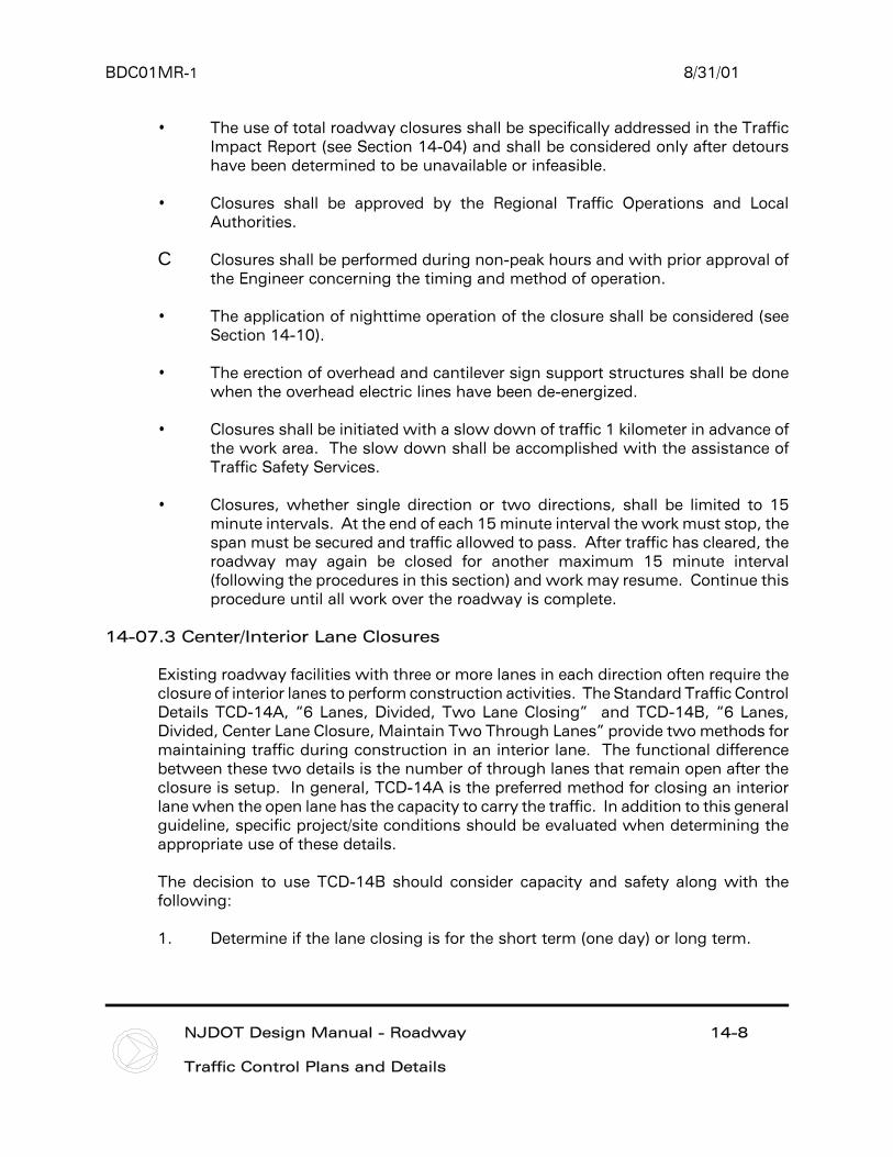
Structures
Work area needs were considered during easement procurement(i.e. space is needed adjacent to a major structure for a form lay downsite).
Sufficient room is provided between new foundations and existing roadways for the excavation, a working area, and a barrier.
Access to structure locations can be provided which will permit a free flow for transit mixers or trucking and the access is compatible with traffic patterns and safe to merge.
Pedestrian traffic at structures was addressed and protectionprovided where required.
Design of bridges which require falsework construction over trafficconditions allows a 5.0 m (16 feet) minimum clearance to the bottom of the falsework.
Falsework requires illumination for nighttime traffic.
Traffic flow for phased construction of elevated or depressedstructures was considered (i.e. elevation differences that mayrequire the use of sheet piling or some other technique to maintaintraffic lanes were evaluated).
In high volume areas, construction of temporary over/under passes for hauling equipment were considered to avoid traffic conflicts.
Adequate protection has been provided for the roadway or water course under the structure.
Traffic stoppage and time limits for stoppage for setting steel over roadway have been indicated.
BDC01MR-1 8/31/01
Design / Quality Control YES NO
NJDOT Design Manual - Roadway 14-37
Traffic Control Plans and Details
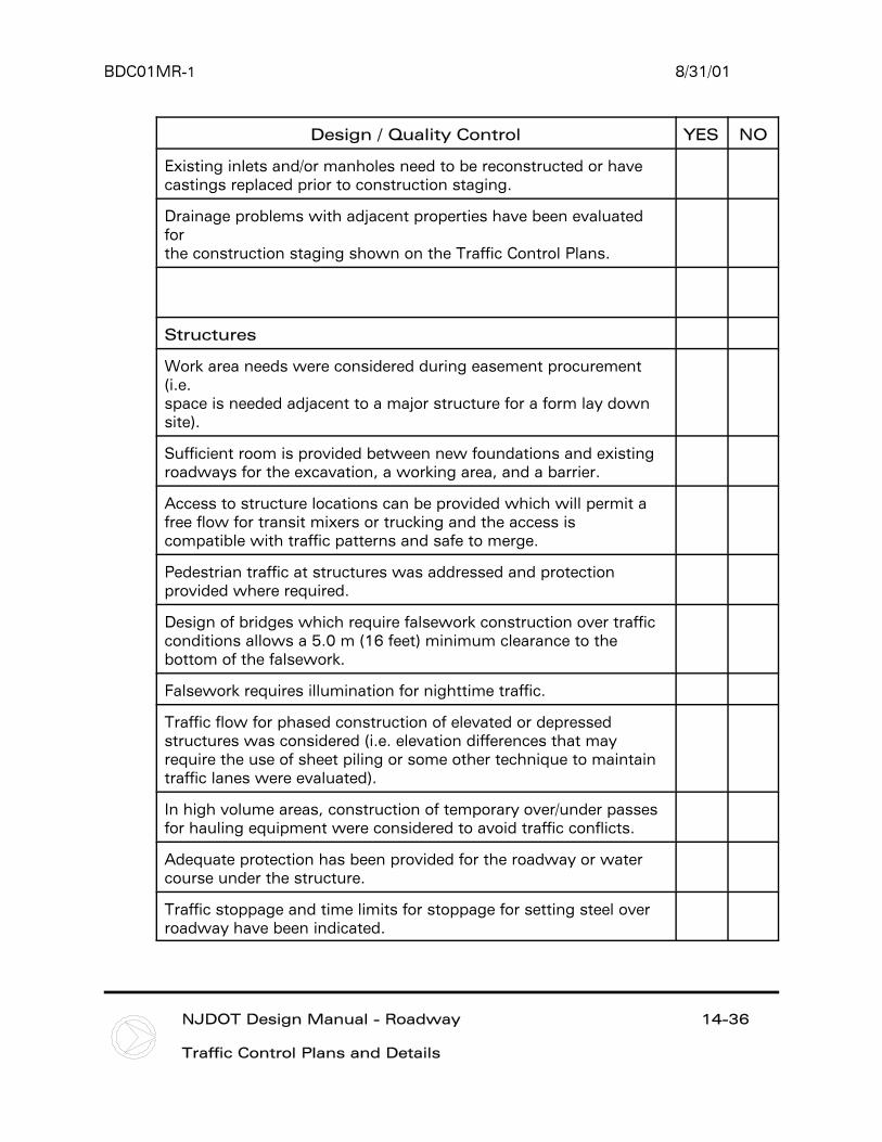
Signing
Signing diagram is clear and understandable.
Traffic Control signing meets MUTCD standards and the traffic needs in each phase.
Traffic Control signing is shown for all detours.
Variable message signs and/or highway advisory radio are needed.
Special signs are needed for businesses and safety of pedestrians.
Existing highway signing needs refurbishing or replacement prior toconstruction staging.

BDC01MR-1 8/31/01
NJDOT Design Manual - Roadway 14-38
Traffic Control Plans and Details
REFERENCES
Section 14-03 Traffic Control and Staging Plans
C ADU dated May 12, 1992 - “Stage Construction”C ADU dated January 22, 1990 - “Use of Unbound Materials in
Resurfacing and Widening”
Section 14-04 Traffic Impact Report
C ADU 93075 dated February 3, 1994 - “Traffic Impact Reports”
Section 14-05 Development of Traffic Control Design Parameters
C June 24, 1996 Departmental Letter - “Mitigation of Congestion onConstruction Projects”
C ADU 92034 dated December 8, 1992 - “Traffic Control in ConstructionZones”
Section 14-06 Traffic Stripes and Traffic Markings
• ADU 94001 dated October 11, 1995 - “Revised Policy and SpecificationsFor Traffic Stripes and Traffic Markings”
Section 14-07 Lane and Road Closures
C ADU dated April 11, 1984 - “Maintenance and Protection of Traffic”C December 7, 1967 Departmental letter - “Alternate Traffic Routes,
Department Responsibility”, James R. Schyler, State Highway Engineerto Messrs. Cunningham, Doll, all Division Heads, Bureau Heads.
Section 14-08 Precast Concrete Curb Construction Barrier
C ADU 93020 dated September 20, 1993 - “Precast Concrete CurbConstruction Barrier”
C ADU dated April 11, 1984 - “Maintenance and Protection of Traffic”C ADU dated January 2, 1980 - “2 Way - 2 Lane”C ADU dated March 6, 1978 - “Traffic Control in Construction Zones”C ADU dated June 3, 1977 - “Traffic Control in Construction Zones”C Policy 1.052-A dated March 7, 1975 - “Detours”

BDC01MR-1 8/31/01
NJDOT Design Manual - Roadway 14-39
Traffic Control Plans and Details
Section 14-09 Movable Construction Barrier
C Letter from Dennis Merida,FHWA to Charles Takacs, NJDOT, datedNovember 20, 1995 - “Precast Concrete Curb Moveable ConstructionBarrier”
Section 14-10 Nighttime Construction
C Second draft of “Design Guidelines for Nighttime Construction” datedSeptember 11, 1996 prepared by Traffic Signal and Safety Engineering.
Section 14-11 Construction Details
C ADU dated November 9, 1990 - “Traffic Control Devices - Give Us aBrake Sign”
C ADU dated August 1, 1988 - “Construction Identification Signs”C ADU dated March 14, 1995 - “Signs - Pay Item”C ADU dated April 11, 1984 - “Maintenance and Protection of Traffic”
Section 14-15 Traffic Control Plan Submission Requirements
• Quality Improvement Advisory, QIA-004 - Coordination with otherAuthorities