Basics of Radio Wave Propagation Range km 200
16
Basics of Radio Wave Propagation Iulian Rosu, YO3DAC / VA3IUL, http://www.qsl.net/va3iul/ Propagation Modes • Ground-wave propagation - The radio waves follow contour of the earth. - The radio waves can Propagate considerable distances. - Ground Wave = Direct Wave + Reflected Wave + Surface Wave - At Medium Wave frequencies (300kHz to 3MHz) and in the lower HF bands (3MHz to 30MHz), aerials tend to be close to the ground (in terms of wavelength). Hence the direct wave and reflected wave tend to cancel each other out (there is a 180° phase shift on reflection). This means that only the surface wave remains. - A surface wave travels along the surface of the earth by virtue of inducing currents in the earth. The imperfectly conducting earth leads to some of its characteristics. Its range depends upon: Frequency, Polarization, Location and Ground Conductivity. - The surface waves die more quickly as the frequency increases: ) ( 200 ) ( MHz f km Range = • Sky-wave propagation In radio communication, skywave or skip refers to the propagation of radio waves reflected or refracted back toward Earth from the ionosphere, an electrically charged layer of the upper atmosphere. Since it is not limited by the curvature of the Earth, skywave propagation can be used to communicate beyond the horizon, at intercontinental distances. It is mostly used in the shortwave frequency bands. - Signal reflected from ionized layer of atmosphere back down to earth. - Signal can travel a number of hops, back and forth between ionosphere and earth’s surface. - Reflection effect caused by refraction. Short-waves (3MHz – 30MHz) generally travel to their destination in four ways: - Directly from one point to another. - Along the ground, bending slightly to follow the curvature of the Earth for some distance. TX RX Direct wave Reflected Wave Ground
Transcript of Basics of Radio Wave Propagation Range km 200
Basics of Radio Wave Propagation
Iulian Rosu, YO3DAC / VA3IUL, http://www.qsl.net/va3iul/
Propagation Modes
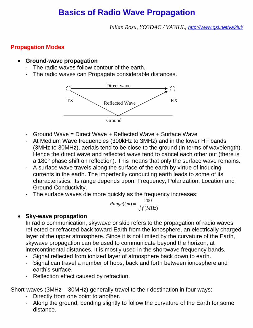
• Ground-wave propagation - The radio waves follow contour of the earth. - The radio waves can Propagate considerable distances.
- Ground Wave = Direct Wave + Reflected Wave + Surface Wave - At Medium Wave frequencies (300kHz to 3MHz) and in the lower HF bands
(3MHz to 30MHz), aerials tend to be close to the ground (in terms of wavelength). Hence the direct wave and reflected wave tend to cancel each other out (there is a 180° phase shift on reflection). This means that only the surface wave remains.
- A surface wave travels along the surface of the earth by virtue of inducing currents in the earth. The imperfectly conducting earth leads to some of its characteristics. Its range depends upon: Frequency, Polarization, Location and Ground Conductivity.
- The surface waves die more quickly as the frequency increases:
)(
200)(
MHzfkmRange =
• Sky-wave propagation In radio communication, skywave or skip refers to the propagation of radio waves reflected or refracted back toward Earth from the ionosphere, an electrically charged layer of the upper atmosphere. Since it is not limited by the curvature of the Earth, skywave propagation can be used to communicate beyond the horizon, at intercontinental distances. It is mostly used in the shortwave frequency bands. - Signal reflected from ionized layer of atmosphere back down to earth. - Signal can travel a number of hops, back and forth between ionosphere and
earth’s surface. - Reflection effect caused by refraction.
Short-waves (3MHz – 30MHz) generally travel to their destination in four ways:
- Directly from one point to another. - Along the ground, bending slightly to follow the curvature of the Earth for some
distance.
TX RX
Direct wave
Reflected Wave
Ground
- Traveling a longer distance than normal before coming back to the Earth's surface, because they are trapped in a layer of the Earth's atmosphere.
- Refracted, or bent, back to Earth by the ionosphere. (The ionosphere is a layer of charged particles called ions, in the Earth's outer atmosphere. These ionized gases make long-distance radio contacts possible on the HF bands.)
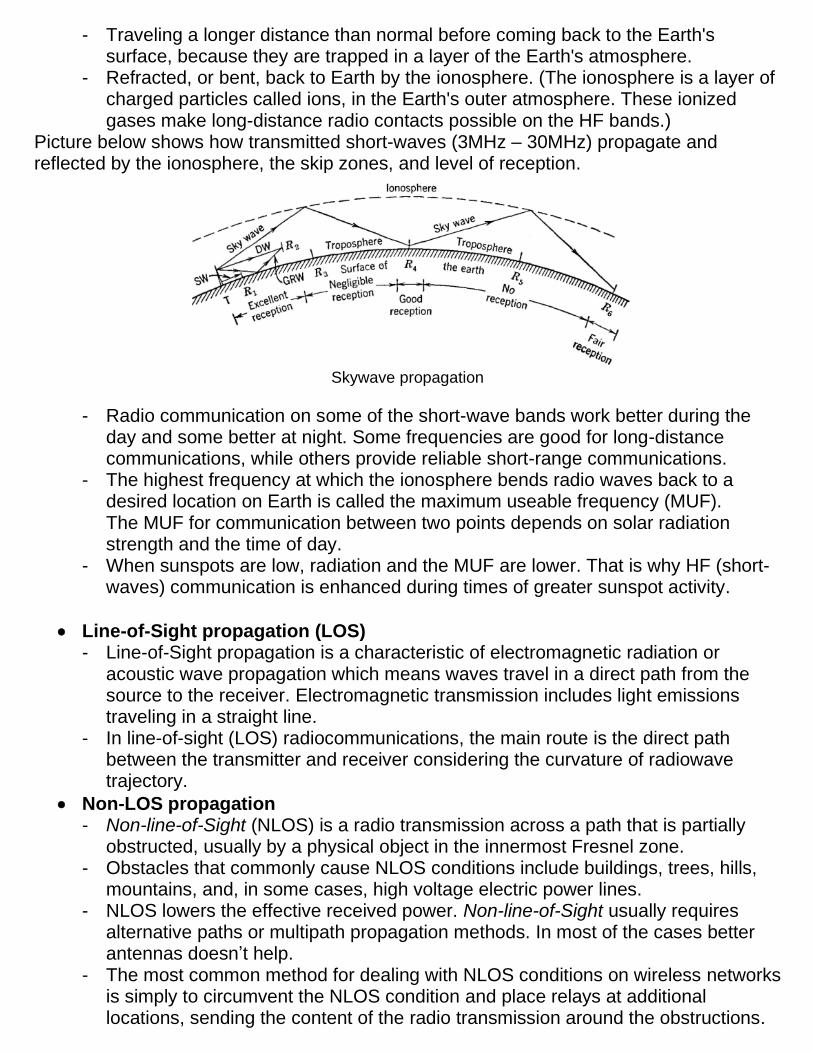
Picture below shows how transmitted short-waves (3MHz – 30MHz) propagate and reflected by the ionosphere, the skip zones, and level of reception.
Skywave propagation
- Radio communication on some of the short-wave bands work better during the day and some better at night. Some frequencies are good for long-distance communications, while others provide reliable short-range communications.
- The highest frequency at which the ionosphere bends radio waves back to a desired location on Earth is called the maximum useable frequency (MUF). The MUF for communication between two points depends on solar radiation strength and the time of day.
- When sunspots are low, radiation and the MUF are lower. That is why HF (short-waves) communication is enhanced during times of greater sunspot activity.
• Line-of-Sight propagation (LOS) - Line-of-Sight propagation is a characteristic of electromagnetic radiation or
acoustic wave propagation which means waves travel in a direct path from the source to the receiver. Electromagnetic transmission includes light emissions traveling in a straight line.
- In line-of-sight (LOS) radiocommunications, the main route is the direct path between the transmitter and receiver considering the curvature of radiowave trajectory.
• Non-LOS propagation - Non-line-of-Sight (NLOS) is a radio transmission across a path that is partially
obstructed, usually by a physical object in the innermost Fresnel zone. - Obstacles that commonly cause NLOS conditions include buildings, trees, hills,
mountains, and, in some cases, high voltage electric power lines. - NLOS lowers the effective received power. Non-line-of-Sight usually requires
alternative paths or multipath propagation methods. In most of the cases better antennas doesn’t help.
- The most common method for dealing with NLOS conditions on wireless networks is simply to circumvent the NLOS condition and place relays at additional locations, sending the content of the radio transmission around the obstructions.
Wave Polarization
• The plane of polarization of a radio wave is the plane in which the E-field propagates with respect to the Earth. - If the E-field component of the radiated wave travels in a plane perpendicular to
the Earth's surface (vertical), the radiation is said to be Vertically Polarized. - If the E-field propagates in a plane parallel to the Earth's surface (horizontal), the
radiation is said to be Horizontally Polarized. - Circular Polarization produces an electric field that rotates as it travels. Circular
polarization falls into two categories, depending on the direction of rotation: ‘right-hand circular’ and ‘left-hand circular’.
• The polarization of a radio wave can rotate as it propagates. - If a Linear polarized wave (vertical or horizontal) reflects off a surface that is not
vertical or horizontal, its polarization will be changed. - One advantage of Circular polarization is that rotation does not affect it: it remains
circular. For this reason, circular polarization is commonly used in links to geostationary satellites at frequencies below 10 GHz.
Direction of Propagation
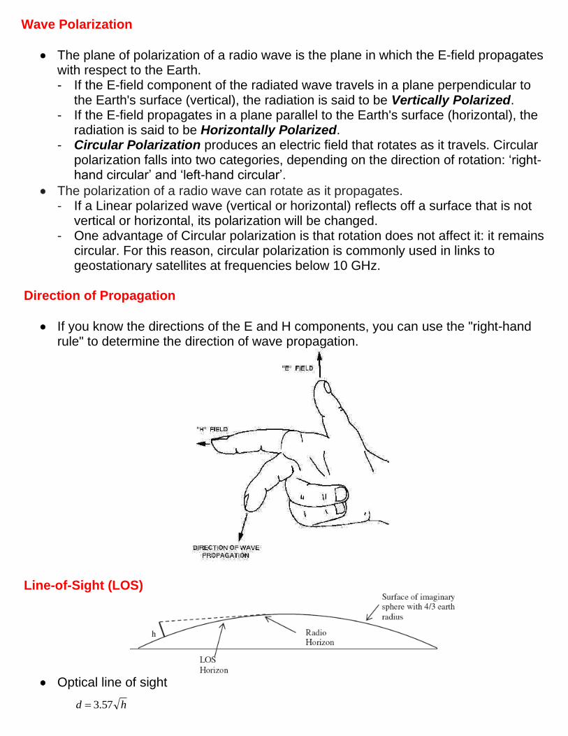
• If you know the directions of the E and H components, you can use the "right-hand rule" to determine the direction of wave propagation.
Line-of-Sight (LOS)
• Optical line of sight
hd 57.3=

• Effective, or radio, line-of-sight
- d = distance between antenna and horizon (km) - h = antenna height (m) - K = adjustment factor to account for refraction, rule of thumb K = 4/3
• Maximum distance between two antennas for LOS propagation:
- h1 = height of antenna one - h2 = height of antenna two
• Line-Of-Sight Wireless Transmission Impairments: - Free space loss - Attenuation and Scattering - Atmospheric absorption - Ducting - Multipath and Fading - Refraction - Reflection
Non-LOS Propagation
• Indirect or Obstructed Propagation - The efficacy of indirect propagation depends upon the amount of margin in the
communication link and the strength of the diffracted or reflected signals. - The operating frequency has a significant impact on the viability of indirect
propagation, with lower frequencies working the best.
• Tropospheric Propagation - Tropospheric propagated signals travel in the part of the atmosphere adjacent to
the surface and extending to about 10km. Such signals are thus directly affected by weather conditions extending over about 1000km or more.
- Consists the reflection or refraction of the radio waves from temperature and moisture layers in the atmosphere.
• Ionospheric Propagation. - Ionosphere is an ionized plasma around the earth that is essential to sky-wave
propagation and provides the basis for nearly all HF communications beyond the horizon. These are the ionospheric layers around the Earth:
Ionospheric Layers
hd = 57.3
( )2157.3 hh +

Fresnel Zone
• Radio waves diffracted by objects can affect the strength of the received signal. This happens even though the obstacle does not directly obscure the direct visual path. This area, known as the "Fresnel Zone", must be kept clear of all obstructions.
d1 and d2 = km, f = GHz, h = meters
Fresnel Zones
• The 1st Fresnel zone is a spheroid space formed within the trajectory of the path when the path difference when radio wave energy reaches the receiver by the shortest distance, and when it gets there by another route, is within λ/2. - If a signal is vertically polarized and it deflects off a horizontal object such as a
flat roof, and then bounces up to a receiving antenna, and if the roof is within the 1st region of the Fresnel zone, the resulting signal will be inverted relative to the original signal.
- If a signal is horizontally polarized and it deflects off a horizontal object such as a flat roof, and then bounces up to a receiving antenna, and if the roof is within the 1st region of the Fresnel zone, the resulting signal will be received favorably - as it will be in-phase.
- The 2nd Fresnel region surrounds the 1st Fresnel region but excludes the first region. If a reflective object is located in the 2nd Fresnel region, the stray sine-wave which has bounced from this object and has been captured by the receiver will be shifted more than 90º but less than 270º because of the increased path length, and will potentially be received out-of-phase.
- The 3rd Fresnel region surrounds the 2nd Fresnel region and deflected waves captured by the receiver will have the same effect as a wave in the 1st region. S So, the sine wave will have shifted more than 270º but less than 450º (ideally it would be a 360º shift) and will therefore arrive at the receiver with the same shift as a signal might arrive from the 1st region. A wave deflected from this region has
the potential to be shifted precisely one wavelength so that it is exactly in sync with the line-of-sight wave when it arrives at the receiving antenna.
• Odd-numbered Fresnel zones have relatively intense field strengths, whereas even numbered Fresnel zones are nulls.
• When the radio signal pass from site A to site B, the lack of adequate Fresnel Zone clearance caused signal diffraction, and degradation of the radio signal.
• If the 1st Fresnel zone is not clear, then free-space loss does not apply and an adjustment term must be included. To avoid this, have to: - Use an antenna with a narrower lobe pattern, usually a higher gain antenna will
achieve this. - Raise the antenna mounting point on Site A and/or Site B.
Free Space Loss
• Radio waves travel from a source into the surrounding space at the “speed of light” (approximately 3.0 x 10⁸ meters per second) when in “free space”. Literally, “free space” should mean a vacuum, but clear air is a good approximation to this.
Free Space Path Loss(dB) = 27.6 – 20*LOG(Frequency(MHz)) – 20*LOG(Distance(meter))
• The equations for free-space loss and link-loss can be used between two antennas only for distances greater than the near-field distance of each antenna.
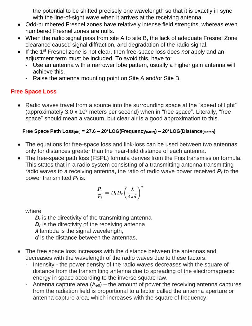
• The free-space path loss (FSPL) formula derives from the Friis transmission formula. This states that in a radio system consisting of a transmitting antenna transmitting radio waves to a receiving antenna, the ratio of radio wave power received Pr to the power transmitted Pt is: where Dt is the directivity of the transmitting antenna Dr is the directivity of the receiving antenna λ lambda is the signal wavelength, d is the distance between the antennas,
• The free space loss increases with the distance between the antennas and decreases with the wavelength of the radio waves due to these factors: - Intensity - the power density of the radio waves decreases with the square of
distance from the transmitting antenna due to spreading of the electromagnetic energy in space according to the inverse square law.
- Antenna capture area (Aeff) – the amount of power the receiving antenna captures from the radiation field is proportional to a factor called the antenna aperture or antenna capture area, which increases with the square of frequency.

Atmospheric absorption
• The atmosphere, due to the many different gases, water and particles contained therein, absorbs and transmits many different wavelengths of electromagnetic radiation.
• The wavelengths that pass through the atmosphere unabsorbed constitute the "atmospheric windows."
• A significant atmospheric effect is that of attenuation due to rain. Below about 10GHz, rain fading is not very significant, but, at higher microwave frequencies, it becomes the major factor limiting path length, particularly in areas that experience high levels of rainfall. In addition to the attenuation of electromagnetic waves, rain and other precipitation tend to cause depolarization of the wave.
Atmospheric absorption
Ducting
• Atmospheric ducting is a mode of propagation of electromagnetic radiation, usually in the lower layers of Earth’s atmosphere, where the waves are bent by atmospheric refraction. It causes long distance propagation of radio signals in bands that would normally be limited to line of sight.
• A duct is something that will confine whatever is traveling along it into a narrow ‘pipe’.
• The atmosphere can assume a structure that will produce a similar effect on radio waves. When a radio wave enters a duct, it can travel with low loss over great distances. The atmosphere will then act in the manner of a giant optical fiber, trapping the radio wave within the layer of high refractive index.
• A wave trapped in a duct can travel beyond the radio horizon with very little loss, producing signal levels within a few dB of the free-space level.
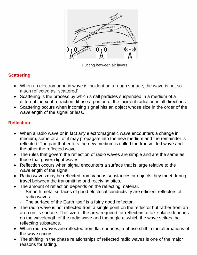
Ducting between air layers
Scattering
• When an electromagnetic wave is incident on a rough surface, the wave is not so much reflected as “scattered”.
• Scattering is the process by which small particles suspended in a medium of a different index of refraction diffuse a portion of the incident radiation in all directions.
• Scattering occurs when incoming signal hits an object whose size in the order of the wavelength of the signal or less.
Reflection
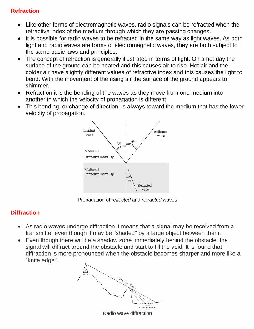
• When a radio wave or in fact any electromagnetic wave encounters a change in medium, some or all of it may propagate into the new medium and the remainder is reflected. The part that enters the new medium is called the transmitted wave and the other the reflected wave.
• The rules that govern the reflection of radio waves are simple and are the same as those that govern light waves.
• Reflection occurs when signal encounters a surface that is large relative to the wavelength of the signal.
• Radio waves may be reflected from various substances or objects they meet during travel between the transmitting and receiving sites.
• The amount of reflection depends on the reflecting material. - Smooth metal surfaces of good electrical conductivity are efficient reflectors of
radio waves. - The surface of the Earth itself is a fairly good reflector.
• The radio wave is not reflected from a single point on the reflector but rather from an area on its surface. The size of the area required for reflection to take place depends on the wavelength of the radio wave and the angle at which the wave strikes the reflecting substance.
• When radio waves are reflected from flat surfaces, a phase shift in the alternations of the wave occurs
• The shifting in the phase relationships of reflected radio waves is one of the major reasons for fading.
Refraction
• Like other forms of electromagnetic waves, radio signals can be refracted when the refractive index of the medium through which they are passing changes.
• It is possible for radio waves to be refracted in the same way as light waves. As both light and radio waves are forms of electromagnetic waves, they are both subject to the same basic laws and principles.
• The concept of refraction is generally illustrated in terms of light. On a hot day the surface of the ground can be heated and this causes air to rise. Hot air and the colder air have slightly different values of refractive index and this causes the light to bend. With the movement of the rising air the surface of the ground appears to shimmer.
• Refraction it is the bending of the waves as they move from one medium into another in which the velocity of propagation is different.
• This bending, or change of direction, is always toward the medium that has the lower velocity of propagation.
Propagation of reflected and refracted waves
Diffraction
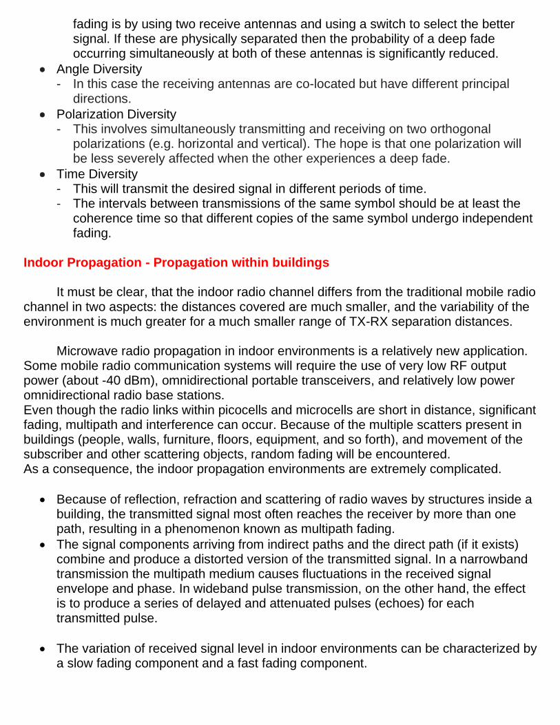
• As radio waves undergo diffraction it means that a signal may be received from a transmitter even though it may be "shaded" by a large object between them.
• Even though there will be a shadow zone immediately behind the obstacle, the signal will diffract around the obstacle and start to fill the void. It is found that diffraction is more pronounced when the obstacle becomes sharper and more like a "knife edge".
Radio wave diffraction

• Diffraction is the name given to the mechanism by which waves enter into the shadow of an obstacle.
• Diffraction occurs at the edge of an impenetrable body that is large compared to wavelength of radio wave.
• A radio wave that meets an obstacle has a natural tendency to bend around the obstacle. The bending, called diffraction, results in a change of direction of part of the wave energy from the normal line-of-sight path. This change makes it possible to receive energy around the edges of an obstacle.
• The ratio of the signal strengths without and with the obstacle is referred to as the diffraction loss. The diffraction loss is affected by the path geometry and the frequency of operation. The signal strength will fall by 6 dB as the receiver approaches the shadow boundary, but before it enters into the shadow region.
• Deep in the shadow of an obstacle, the diffraction loss increases with 10*log(frequency). So, if double the frequency, deep in the shadow of an obstacle the loss will increase by 3 dB. This establishes a general truth, namely that radio waves of longer wavelength will penetrate more deeply into the shadow of an obstacle.
Multipath
• In radio communication, multipath is the propagation phenomenon that results in radio signals reaching the receiving antenna by two or more paths. Causes of multipath include atmospheric ducting, ionospheric reflection and refraction, and reflection from water bodies and terrestrial objects such as mountains and buildings.
• Multipath propagation causes multipath interference, including constructive and destructive interference, and phase shifting of the signal; destructive interference causes fading. This may cause a radio signal to become too weak in certain areas to be received adequately, so multipath propagation can be detrimental in radio communication systems.
• Multipath is a term used to describe the multiple paths a radio wave may follow between transmitter and receiver. Such propagation paths include the ground wave, ionospheric refraction, reradiation by the ionospheric layers, reflection from the Earth's surface or from more than one ionospheric layer, etc.
• If the two signals reach the receiver in-phase (both signals are at the same point in the wave cycle when they reach the receiver), then the signal is amplified. This is known as an “upfade.” If the two waves reach the receiver out-of-phase (the two signals are at opposite points in the wave cycle when they reach the receiver), they weaken the overall received signal. If the two waves are 180º apart when they reach the receiver, they can completely cancel each other out so that a radio does not receive a signal at all. A location where a signal is canceled out by multipath is called a “null” or “downfade.”
• If the reflecting surfaces that cause the multipath situation do not move, the locations of the maxima and minima will not move, hence the name ‘standing wave’.
• The depth of the null in a standing wave pattern is dependent upon the magnitude of the reflection coefficient of any reflecting surface.
• The Effects of Multipath Propagation

- Multiple copies of a signal may arrive at different phases - If phases add destructively, the signal level relative to noise declines, making
detection more difficult. - Dealy Spread resulting in Intersymbol interference (ISI) - one or more delayed
copies of a pulse may arrive at the same time as the primary pulse for a subsequent bit.
Multipath Propagation
Fading
• In wireless communications, fading is variation of the attenuation of a signal with various variables. These variables include time, geographical position, and radio frequency. Fading is often modeled as a random process. A fading channel is a communication channel that experiences fading. In wireless systems, fading may either be due to multipath propagation, referred to as multipath-induced fading, weather (particularly rain), or shadowing from obstacles affecting the wave propagation, sometimes referred to as shadow fading.
• There is a large dependence of fading on distance. - The probability of a fade of a particular depth increases with the cube of distance.
Thus, as the distance is doubled, the probability of a particular fade depth increases by a factor of eight. Or, alternatively, the fade for a given probability increases by 9 dB. So, doubling the distance will increase the free-space loss by 6 dB, and increase the probability of fading by 9 dB, thus increasing the overall link-budget loss by 15 dB.
• There is a slight dependence of fading on frequency. Increasing the frequency by 1GHz will decrease the probability of a fade by a factor of 1.08.
• There is a fairly strong dependence of fading on the height of the path above sea level. - There is simply less atmosphere at higher altitudes and therefore the effect of
atmospheric fading is smaller. - For every 1000 meter increase in altitude the required fade margin reduces by 10
dB.
• Types of Fading - Fast fading - occurs when the coherence time of the channel is small relative to
the delay constraint of the channel. Fast fading causes rapid fluctuations in phase and amplitude of a signal if a transmitter or receiver is moving or there are changes in the radio environment (e.g. car passing by). If a transmitter or receiver is moving, the fluctuations occur within a few wave lengths. Because of its short distance fast fading is considered as small-scale fading.

- Slow fading - arises when the coherence time of the channel is large relative to the delay constraint of the channel. Slow fading occurs due to the geometry of the path profile. This leads to the situation in which the signal gradually gets weaker or stronger.
- Flat fading – occurs when the coherence bandwidth of the channel is larger than the bandwidth of the signal.
- Selective fading – occurs when the coherence bandwidth of the channel is smaller than the bandwidth of the signal.
- Rayleigh fading - assume that the magnitude of a signal that has passed through a communications channel will vary randomly.
- Ricean fading - occurs when one of the paths, typically a line of sight signal, is much stronger than the others.
- Nakagami fading - occurs for multipath scattering with relatively larger time-delay spreads, with different clusters of reflected waves.
- Weibull fading - considers a signal composed of clusters of one multipath wave, each propagating in a non-homogeneous environment.
Types of Fading
Diversity Techniques
• In telecommunications, a diversity scheme refers to a method for improving the reliability of a message signal by using two or more communication channels with different characteristics. Diversity is mainly used in radio communication and is a common technique for combatting fading and co-channel interference and avoiding error bursts. It is based on the fact that individual channels experience different levels of fading and interference. Multiple versions of the same signal may be transmitted and/or received and combined in the receiver.
Fade margin on the transmitter path is not an efficient solution at all, and one alternate solution is to take the advantage of the statistical behavior of the fading channel. This is the basic concept of Diversity, where two or more inputs at the receiver are used to get uncorrelated signals.
• Frequency Diversity - Different frequencies mean different wavelengths. The hope when using
frequency diversity is that the same physical multipath routes will not produce simultaneous deep fades at two separate wavelengths.
• Space Diversity - Deep multipath fade has unlucky occurrence when the receiving antenna is in
exactly in the ‘wrong’ place. One method of reducing the likelihood of multipath
fading is by using two receive antennas and using a switch to select the better signal. If these are physically separated then the probability of a deep fade occurring simultaneously at both of these antennas is significantly reduced.
• Angle Diversity - In this case the receiving antennas are co-located but have different principal
directions.
• Polarization Diversity - This involves simultaneously transmitting and receiving on two orthogonal
polarizations (e.g. horizontal and vertical). The hope is that one polarization will be less severely affected when the other experiences a deep fade.
• Time Diversity - This will transmit the desired signal in different periods of time. - The intervals between transmissions of the same symbol should be at least the
coherence time so that different copies of the same symbol undergo independent fading.
Indoor Propagation - Propagation within buildings
It must be clear, that the indoor radio channel differs from the traditional mobile radio channel in two aspects: the distances covered are much smaller, and the variability of the environment is much greater for a much smaller range of TX-RX separation distances.
Microwave radio propagation in indoor environments is a relatively new application. Some mobile radio communication systems will require the use of very low RF output power (about -40 dBm), omnidirectional portable transceivers, and relatively low power omnidirectional radio base stations. Even though the radio links within picocells and microcells are short in distance, significant fading, multipath and interference can occur. Because of the multiple scatters present in buildings (people, walls, furniture, floors, equipment, and so forth), and movement of the subscriber and other scattering objects, random fading will be encountered. As a consequence, the indoor propagation environments are extremely complicated.
• Because of reflection, refraction and scattering of radio waves by structures inside a building, the transmitted signal most often reaches the receiver by more than one path, resulting in a phenomenon known as multipath fading.
• The signal components arriving from indirect paths and the direct path (if it exists) combine and produce a distorted version of the transmitted signal. In a narrowband transmission the multipath medium causes fluctuations in the received signal envelope and phase. In wideband pulse transmission, on the other hand, the effect is to produce a series of delayed and attenuated pulses (echoes) for each transmitted pulse.
• The variation of received signal level in indoor environments can be characterized by a slow fading component and a fast fading component.

• The slow fading or the loss-distance relationship characterizes the fact that the average signal level decreases, normally monotonically, as the distance from the transmitter increases.
• The fast fading component characterizes the fluctuation of the signal level from this mean (slow fading curve). This more rapid variation is caused by the interference of the received multipath signals and is generally determined in terms of the distribution and statistics of the signal level from the mean.
While fast fading in quasi-static indoor environments has been routinely examined, study of fading caused by activity by people on an essentially fixed indoor radio link has to be taken into consideration. The knowledge of this fading is also very important in the design of a reliable radio system.
• Fades with magnitude of more than 10 dB could be caused by the movement of people around the radio link. Deeper fading is more likely to be observed when there is more people activity.
• For measurements, traditional practice has been to average the measured signal by moving the transmitter or the receiver over a spatial area having linear dimensions of 10 to 20 wavelengths (often in a circular path) to remove the rapid signal variation.
• In both outdoor mobile and indoor environments, the signal level in the space changes from point to point due to the standing wave pattern as a result of the interference of the multipaths. In outdoor mobile measurements, at the time when the effect of the atmosphere is negligible, the signal level in the space is usually sampled radially.
• The variation of signal level at a local area is generally referred to as fast fading.
• Fast fading is usually reported in terms of the distribution of the signal level from the local average, and the associated statistics, which are very useful in determining the reliability of a radio access design. Although the spacing of the samples in time may vary depending on the speed of the mobile receiver, the fast fading statistics will not change as long as the sampling is performed uniformly.
• The fast fading of the signal level observed in outdoor propagation measurements generally follows a Rayleigh distribution when there is no dominant line-of-sight (LOS) power contribution, and Rician distribution when a dominant LOS power component exists.
• In the indoor environment the addition of the random multipath signals can only be approximated by a Gaussian distributed signal, and therefore the envelope of the addition of the LOS ray and random rays is only approximately Rayleigh or Rician distributed.
Some studies encountered about 3 dB less penetration loss at 1900 MHz than 800 MHz. This may due to that typical building walls were somewhat frequency selective, and tended to favor frequencies in the area of 1900 MHz over 800 MHz frequencies. This is understandable, since a wall can be considered as a dielectric structure containing conducting objects such a structural steel, window casements, etc. Meanwhile, in the non-metallic single-family-type homes, the important materials are glass, brick and mortar, dry wall, plywood, wood, and cinder block. In these structures, the

penetration is primarily through windows, walls, and the roof where the loss through the material is relatively low and goes up as the frequency increases. Propagation into (and inside) buildings has to some extent a more complex multipath structure than that of the terrestrial mobile radio channel. This is mainly because of the building structure, layout of rooms and, most importantly, the type of construction materials. For example, a factory building is quite different to an office building both in its structure and the materials used. There are also variations in the types of materials used in internal partitions, walls to outside and floors as well as the sizes and percentage of windows. The type of objects inside the buildings, which may be lossy or good reflectors, also provide an undeterministic situation. Building attenuation for houses, which are metallic, side metallic or wood constructed, were found to vary from 2 dB to 24 dB, increasing with frequency.
• Another important analysis factor is the physical surroundings, whereas the wide variations in field intensity can be attributed to its nature. The RF field may enter the building directly from the transmitting antenna or may be bounced off the many reflecting surfaces presented by the surrounding buildings. For example, a comparison done between penetration losses in urban and suburban environments indicates that the average penetration loss for the urban group that is approximately 5 dB greater.
• The reflection of radiowaves from sheet glass depends on the angle of incidence of the signal, therefore the angle of arrival of the signal relative to the unshielded side of the building has also to be included. Some brands of mirror (light reflective) glass have thin metal film coatings which may be detrimental to radio waves penetration.
• The energy present in an incident radiowave that does not reflect from a surface must penetrate that surface. - The reflection coefficient of the material affects the amount that penetrates into
the material. - Once inside the material, the wave will travel through the material. In most
materials, the strength will decay as it travels. - Good insulators tend to allow the wave to propagate through them with only low
loss. - Good conductors tend to reflect the radio wave at its surface and very little signal
passes through
• Signal propagation within a building is strongly dependent upon the topology, construction and content of the building and is influenced by the following: - Reflection from flat conducting surfaces such as metal cladding, galvanized
roofing, foil backed plasterboard, metal coated anti-reflection glazing or any surfaces greater than a wavelength in size.
- Re-radiation from thin conductors such as pipe work, electrical wiring, steel frame works and any conductor of greater than a half wave in length.
- Absorption by lossy materials such as damp concrete, stonework and people. - People moving around: Additional multipath induced attenuation of 10 dB
- Buildings with few metal and hard partitions: RMS delay spread of 30 to 60 ns - Buildings with metal/open aisles: RMS delay spread of up to 300 ns - Between floors:
o Concrete/steel flooring yields less attenuation than steel plate flooring o Metallic tinted windows yield greater attenuation 15 dB for first floor
separation, 6 - 10 dB for next four floors, 1 - 2 dB for each additional floor of separation
• A building with an open-plan structure whose walls contain large glass windows will introduce little extra path loss (less than 5 dB), whereas a building with thick stone walls and small windows and an internal structure consisting of many solid walls can introduce extra path loss amounting to several tens of dB.
• Physical Effects of Indoor Propagation: - Signal decays much faster - Coverage contained by walls, etc. - Walls, floors, furniture attenuate/scatter radio signals
• Indoor Propagation Path Loss formula: Path_Loss[dB] = Unit_Loss[dB] + n*10*log(d) = k*F + N*W[dB]
where: Unit loss = power loss (dB) at 1m distance n = power-delay index d = distance between transmitter and receiver k = number of floors the signal traverses F = loss per floor N = number of walls the signal traverses W = loss per wall
References:
1. Essentials of Radio Wave Propagation – C. Haslett 2. Introduction to RF Propagation – J. Seybold 3. Radio Propagation and Adaptive Antennas for Wireless Communication Links – N. Blaunstein, C.
Christodoulou 4. ARRL Handbook 1995 – 2008 5. Radio Propagation course – prof. R. Katz – University of Berkeley 6. Penetration and transmission of UHF radio waves into/through buildings - Noelia Vàzquez Mejuto 7. Measurements of PCS Microwave Propagation in Buildings – Y. Tang, H. Sobol 8. A Statistical Model for Indoor Multipath Propagation - A. Saleh, R. Vanenzuela 9. Applied Microwave and Wireless Magazine – 1990 - 2002
home: http://www.qsl.net/va3iul/