BASIC DESIGN STUDY REPORT ON THE PROJECT FOR …open_jicareport.jica.go.jp/pdf/11821931_01.pdf ·...
105
No. BASIC DESIGN STUDY REPORT ON THE PROJECT FOR EXPANSION OF RADIO BROADCASTING COVERAGE IN THE REMOTE AREA IN THE REPUBLIC OF INDONESIA MARCH, 2006 JAPAN INTERNATIONAL COOPERATION AGENCY 06-027 JR GM
Transcript of BASIC DESIGN STUDY REPORT ON THE PROJECT FOR …open_jicareport.jica.go.jp/pdf/11821931_01.pdf ·...

No.
BASIC DESIGN STUDY REPORT ON
THE PROJECT FOR
EXPANSION OF
RADIO BROADCASTING COVERAGE IN THE REMOTE AREA
IN THE REPUBLIC OF INDONESIA
MARCH, 2006
JAPAN INTERNATIONAL COOPERATION AGENCY
06-027
JR
GM

PREFACE
In response to a request from the Government of the Republic of Indonesia, the Government of
Japan decided to conduct a basic design study on the Project for Expansion of Radio Broadcasting
Coverage in the Remote Area and entrusted the study to the Japan International Cooperation Agency
(JICA).
JICA sent to Indonesia a study team from November 27 to December 23, 2005.
The team held discussions with the officials concerned of the Government of Indonesia, and
conducted a field study at the study area. After the team returned to Japan, further studies were made.
Then, a mission was sent to Indonesia in order to discuss a draft basic design, and as this result, the
present report was finalized.
I hope that this report will contribute to the promotion of the project and to the enhancement of
friendly relations between our two countries.
I wish to express my sincere appreciation to the officials concerned of the Government of the
Republic of Indonesia for their close cooperation extended to the teams.
March 2006
Seiji Kojima
Vice President
Japan International Cooperation Agency

March, 2006
Letter of Transmittal
We are pleased to submit to you the basic design study report on the Project for Expansion of
Radio Broadcasting Coverage in the Remote Area in the Republic of Indonesia.
This study was conducted by NHK Integrated Technology Inc., under a contract to JICA, during
the period from November, 2005 to March, 2006. In conducting the study, we have examined the
feasibility and rationale of the project with due consideration to the present situation of Indonesia and
formulated the most appropriate basic design for the project under Japan’s grant aid scheme.
Finally, we hope that this report will contribute to further promotion of the project.
Very truly yours,
Akira Nagase Chief Consultant, Basic design study team on the Project for Expansion of Radio Broadcasting Coverage in the Remote Area
NHK Integrated Technology Inc.

Project Sites
W E
S
N
Toli-Toli
Tarakan
Tarakan Airport
Tarakan Port
Project Site
RRI Tarakan Broadcast Station
Radar (Air Force)
8.0 km4.0 km 0
W E
S
N
RRI Tarakan MW Transmitting Station
Toli-Toli Port
Project Site
RRI Toli-ToliBroadcast Station
To Airport
3.0 km1.5 km0
W E
S
N
RRI Toli-Toli MW Transmitting Station
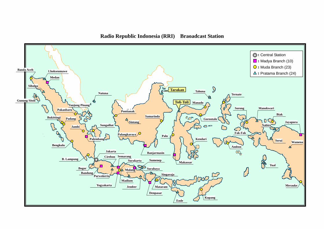
Radio Republic Indonesia (RRI) Braoadcast Station
Lhokseumawe
Medan
Banda Aceh
Tanjung Pinang
Bukittingi Padang
Bengkulu
Sungailiat
Palembang
B. Lampung
Jakarta
Bogor Bandung
Yogyakarta
Purwokerto
Cirebon SemarangSurakarta
Madium
Malang
Jember
Surabaya
Sumenep
Singaraja
Denpasar
Mataram
Ende Kupang
Makassar
Kendari Palu
Toli-Toli
Gorontalo
Manado
Banjarmasin
Palangkaraya
Sintang
Pontianak Samarinda
Tarakan TahunaTernate
Ambon
Sorong Manokwari
Biak
Nabire
Fak-Fak
Serui Wamena
Jayapura
Merauke
Tual
Natuna
Pakanbaru
Jambi
:Central Station :Madya Branch (10) :Muda Branch (23) :Pratama Branch (24)
Gunung Sitoli
Sibolga

List of Figures & Tables
Table 2-1 : Equipment Needed for the MW Broadcasting Systems
Table 2-2 : List of Equipment
Table 2-3 : Table of Items for Which the Governments of the Two Countries Will Be Respectively Responsible
Table 2-4 : List of Main Equipment and Countries of Production Thereof
Table 2-5 : Work Implementation Schedule
Table 2-6 : Periodical Check and Maintenance Items for the 10kW Transmitters
Table 2-7 : MW Transmitting Antenna Periodical Check and Maintenance Items
Fig. 2-1 : The MW Radio Broadcasting System of the Toli-Toli and Tarakan Broadcasting Stations
Fig. 2-2 : The MW and FM Broadcasting Service Areas of the Toli-Toli Broadcasting Station
Fig. 2-3 : The MW and FM Broadcasting Service Areas of the Tarakan Broadcasting Station
Fig. 2-4 : Toli-Toli Broadcasting Station / Site Layout of MW Radio Transmitting Station
Fig. 2-5 : Tarakan Broadcasting Station / Site Layout of MW Radio Transmitting Station
Fig. 2-6 : Toli-Toli & Tarakan Broadcasting Station / Equipment Layout of MW Radio Transmitting Station
Fig. 2-7 : Toli-Toli & Tarakan Broadcasting Station / Scope of Works on Incidental Facilities in the Transmitter Room
Fig. 2-8 : Toli-Toli Broadcasting Station / Floor Layout of FM Transmitter Room
Fig. 2-9 : Toli-Toli Broadcasting Station / Floor Layout of Continuity Studio
Fig. 2-10 : Tarakan Broadcasting Station / Floor Layout of FM Transmitter Room
Fig. 2-11 : Tarakan Broadcasting Station / Floor Layout of Continuity Studio
Fig. 2-12 : Toli-Toli & Tarakan Broadcasting Station / Overall Block Diagram of MW Broadcasting System
Fig. 2-13 : Toli-Toli & Tarakan Broadcasting Station / Block Diagram of MW Transmitting System
Fig. 2-14 : Toli-Toli & Tarakan Broadcasting Station / Block Diagram of 10kW MW Transmitter
Fig. 2-15 : Toli-Toli & Tarakan Broadcasting Station / Block Diagram of 40kVA AVR
Fig. 2-16 : Toli-Toli & Tarakan Broadcasting Station / External View of Program Input & Monitoring Rack and STL/Measuring Rack
Fig. 2-17 : Toli-Toli & Tarakan Broadcasting Station / Elevation of 65m MW Transmitting Antenna
Fig. 2-18 : Toli-Toli Broadcasting Station / Block Diagram of MW Broadcast Program Transmission
Fig. 2-19 : Tarakan Broadcasting Station / Block Diagram of MW Broadcast Program Transmission

Fig. 2-20 : Toli-Toli Broadcasting Station / Block Diagram of Power Supply (Broadcasting Station Side)
Fig. 2-21 : Tarakan Broadcasting Station / Block Diagram of Power Supply (Broadcasting Station Side)
Fig. 2-22 : Toli-Toli Broadcasting Station / Elevation of 65 m Self-Supporting Tower
Fig. 2-23 : Tarakan Broadcasting Station / Elevation of 65 m Self-Supporting Tower

Abbreviations
AC : Alternating Current
A/C : Air Conditioner
A/D : Analog/Digital
ADA : Audio Distribution Amplifier
AES : Audio Engineering Society
AM : Amplitude Modulation
ANT : Antenna
ATT : Attenuator
ATU : Antenna Tuning Unit
AVC : Automatic Voltage Control
AVR : Automatic Voltage Regulator
BAPPENAS : National Development Planning Agency
BPF : Band Pass Filter
CH : Channel
COAX : Coaxial
CoS : Changeover Switch
CTR : Cassette Tape Recorder
DAW : Digital Audio Workstation
DC : Direct Current
DHY : Dehydrator
D/L : Dummy Load
E/G : Engine Generator
EIAJ : Standards of Electric Industries Association of Japan
EX : Exciter
F : Fuse
FL : Fluorescent Light
FM : Frequency Modulation
GBHN : Garis-Garis Baser Haluan Negara
HPF : High Pass Filter
HY : Telephone Hybrid
Hz : Hertz
IEC : International Electrotechnical Commission
ISO : Industrial Organization for Standardization
ITU-R : International Telecommunication Union-Radio Communication Sector
IVR : Induction Voltage Regulator
JIS : Japan Industrial Standards
KfW : Kreditanstalt fur Wiederaubau
KOMINFO : Ministry of Communication & Information Technology
LIM : Limiting Amplifier
LPF : Low Pass Filter
MC : Magnet Contactor
MDF : Main Distribution Board
MF : Medium Wave Frequency
MIC : Microphone
MIX : Mixer
MOD : Modulation
MONI : Monitor
N : Neutral
NFB : No Fuse Breaker
OB Light : Obstruction Light
OECD : Organization for Economic Cooperation and Development
OMI : Omni-directional
OP : Open Phase
OS : Oscillator
OSC : Oscilloscope
OV : Over Voltage
P : Phase
PA : Power Amplifier
PDB : Power Distribution Board

PIE : Program Input & Monitoring Equipment
PROPENAS : Program Pembagunan Nasional (2000 ~ 2004)
PS : Power Supply
REPELITA : Rencana Pembanguan Lima Tahun
REPENAS : Rencana Pembangunan Nasional (2004 ~ 2009)
RF : Radio Frequency
RRI : Radio Republic Indonesia
RX : Receiver
SP : Speaker
STL : Studio Transmitter Link
SW : Switcher
TH : Thermal Relay
TRPA : Transistor Power Amplifier
TVRI : Television Republic of Indonesia
TX : Transmitter
UPS : Uninterruptible Power Supply
UV : Under Voltage
V : Volt
VSWR : Voltage Standing Ratio
W : Wire

SUMMARY
The Republic of Indonesia (hereinafter refereed to as “Indonesia”) is the world’s largest
archipelago country, with some 18,000 islands, large and small, stretching east-west over a distance of
approximately 5,000 km and north-south over a distance of around 2,000 km. It has a population of
about 215 million (as of 2003) and a total national territory of about 1.89 million km2 (five times
bigger than Japan). In view of the fact that Indonesia is a multiethnic, multilingual nation with a vast
territory, the government of Indonesia sees radio broadcasting as a means of striving for peaceful
national unity (promotion of wide use of the Indonesian language as the national language, rapid
conveyance of information, etc.) and as a tool for purposes such as promotion of healthy life,
dissemination of education and enhancing communication among its different ethnic groups and
regions. In this situation, the government of Indonesia has been putting effort on dissemination of its
policy and national principle, expansion of public relations regarding such as the National
Development Plan. As printed media towards the multiethnic population of more than 200 million
people and towards the vast land faced an extreme difficulty, the government puts utilization of
broadcasting media as one of its basic policies.
Broadcasting in Indonesia had been managed and supervised by the Department of Radio
Television Film (RTF) under the former Ministry of Information (DEPPEN). At the time of
inauguration of the Wahid government in October 1999, the former Ministry of Information was
abolished together with the RTF as considered that “the information shall be managed not by the
government but by the people”. Consequently, the broadcasting administration service that had been
conducted by the former Ministry of Information became ineffective, resulted in significant decline in
the quality of broadcasting services such as by frequent false reports by broadcasters as well as by the
wave interference due to upsurge of private broadcasting stations. Later in 2002, the Law on
Broadcast (Law No.32/2002 on Broadcast) was enacted , containing the rules such as on ① freedom
of press/expression, ② the role of broadcasting, ③ responsibility of public business, ④ protection
from human right violation by the press, and ⑤ establishment of press regulation agency. Now
under this Law on Broadcast, only the public broadcasting institutions of Radio Republic Indonesia
(radio broadcast service) and Television Republic Indonesia (TV broadcast service) are permitted to do
services on the national network, while commercial broadcasters’ services are limited only in the
specific regions.
Radio Republic Indonesia (RRI) was established in 1945 as the state owned radio broadcasting
station and became a corporation (PERJAN) in August of 2000. Later in October of 2005, RRI has
stipulated as the public broadcast institution (LPP) under the Government Regulation No.11 and No.12.
( 1 )

At the time of establishment, RRI was limited to the island of Java, with a central broadcasting station
in Jakarta and branch stations at Bandung, Purwokerto, Yogyakarta, Surakarta, Sumarang, Malang and
Surabaya. Subsequently, efforts have been put into expanding the area of reception of medium-wave
(MW) radio broadcasts so as to be able to provide stable broadcasting service to all corners of
Indonesia as a public broadcasting operator. Since 1990, RRI has continued to make efforts to
expand its broadcasting service areas through procurement of some 100 new MW broadcast
transmitters with its own funds or with loans (including yen loans). Presently 53 of the 58 radio
stations organized nationwide (not including international radio stations) carry out MW radio
broadcasting service, and about 90% of the country’s population (i.e. about 193 million people) and
80% of the national territory have reception thereof.
In Indonesia’s national development plan formulated in November 2000 (PROPENAS
2000-2004), five cross-cutting issues are identified which are; ① establishment of democratic
political system and maintenance of national unity, ② establishment of rule of law and good
governance, ③ economic reconstruction and strengthening of the base for sustainable and fair
development (reduction of poverty), ④ enhancement of the welfare of the people and creation of
vigorous culture (development of education and science and technology) and ⑤ promotion of
regional development (narrowing of interregional gap). Regarding information and communications
and the mass media, the plan places emphasis on improvement of the quality of information services
and establishes the following activity guiding principles:
i) Making efforts for equal furnishing of information to all classes of Indonesian society
ii) Reporting in such a way as to abide by reporting ethics and to observe the law and human
rights, while recognizing freedom of reporting
iii) Improving the quality of information and communications in the different fields through
research on and application of information and communications technology
iv) Working for improvement of the content of broadcasting and expansion of broadcasting
service in remote areas
The purpose of those guiding principles is to increase the quantity of information available to the
public, to avoid occurrence of distrust of the government by the people, and to eliminate the gap in
opportunity to obtain information between urban and rural areas which jeopardizes national unity.
Besides being conducive to narrowing of the interregional gap, equal access of all of the people of the
country to information is also recognized as a means of promoting the country’s development and
eliminating poverty. In remote area of the country, broadcasting, particularly MW radio broadcasting
which has reception anywhere with inexpensive radio receivers, plays a significant role. As a public
broadcasting institution RRI is expected to carry out the task of “improving and expanding its MW
( 2 )

radio broadcasting network so as to make it possible for all of the people of the country to enjoy the
benefit of radio broadcasting.” Succeeding to PROPENAS, these active guiding principles are placed
in the mid-term national development plan (REPENAS 2004-2009) issued on January 2005.
For the sake of achieving “provision of radio broadcasting service to the whole national
population”, as called for in the national development plan, RRI recognizes the urgent need to build a
nationwide broadcasting network based primarily on improvement and strengthening of MW radio
broadcasting facilities and is therefore in the process of providing 3 of its 5 radio stations that do not
have them with MW radio broadcasting facilities. FM broadcasting services are provided in the
Toli-Toli and Tarakan areas, both located in remote, poverty-stricken regions but their covering areas
are limited because of low power output. Accordingly as things stand, the residents of those regions
are able to obtain hardly any Indonesian information since they can receive only broadcasts from
neighboring Malaysia and the Philippines, which has given rise to the problem of information gap
within the regions. However, in view of budget limitations, it has been difficult to make progress in
that regard concerning the other two broadcasting stations that have been left behind. In order to
remedy that situation the Government of Indonesia has requested the Government of Japan to
implement grant aid project for improving those two MW radio broadcasting stations, one in Toli-Toli
Regency in Central Sulawesi Province and the other at Tarakan Regency in East Kalimantan Province,
with MW radio broadcasting equipment.
In September 2005, the Government of Japan sent the Preliminary Study Team. The study team
surveyed and confirmed the current status of frequency allocation and the project sites. Based on the
results of this preliminary study, the Basic Design Study Team on “The Project for Expansion of Radio
Broadcasting Coverage in the Remote Area in the Republic of Indonesia (hereinafter referred to as “the
Project”) was sent to Indonesia over the period of 28 days from November 27, 2005 to December 24,
2005, to examine the relevance of the Project and to draw up the necessary and most appropriate basic
design for the Project. The study team reviewed and discussed the content of the request with the
relevant parties from the Indonesian side, and conducted the field survey at the project sites.
Since in the discussions with RRI, additional request was made by RRI for the equipment needed
for a fully digitalized studio, the study team reviewed and made priorities in the equipment the
Indonesian side requested from the viewpoint of whether or not and to what extent it was necessary
after having closely examined the whole content of the request, including those additions, and having
identified problems in the situation as it now stands.
After returning to Japan, while taking the contents of the request into consideration, the study
team examined the optimum range, scale and quantity of equipment from the view points of operation
and management capability of RRI, the relevance, the need and socio economical effect of the Project,
and formulated the most appropriate content and the optimal equipment layout. The study team
( 3 )

summed up the content in the Draft Basic Design Report, and revisited Indonesia for 7 days from
March 12 to March 18, 2006 to explain to the relevant parties from the Indonesian side and to make the
final confirmation of the project content through discussion.
The aim of this Project is to furnish the Toli-Toli broadcasting station and the Tarakan
broadcasting station, the only two remaining RRI broadcast stations without MW radio broadcasting
facilities, with MW radio broadcasting system so as to be able to start MW radio broadcasting service
in the Toli-Toli Regency area of Central Sulawesi Province and the Tarakan Regency area of East
Kalimantan Province and thereby attain the goal set forth in the national development plan “to make it
possible for all of the people of the county to enjoy the benefit of radio broadcasting through expansion
of MW radio broadcasting network.”
Based on the premise of using the existing equipment, the study on what would be required as
minimum for the MW radio broadcasting systems results in procuring the following equipment in the
Project.
Equipment for Toli-Toli and Tarakan Broadcasting Station
Equipment Quantity Purpose of use Place to be installed 10kW MW Broadcast Transmitter 2 sets Transmission of MW signal MW Transmitting Station
10kW Dummy Load 2 sets Apparatus for adjustment of the 10kW MW broadcast transmitter MW Transmitting Station
10kW Lightning Protector 2 sets Included in the 10kW MW broadcast transmitter MW Transmitting Station
3-port U-Link Panel 2 sets Switching of MW broadcast transmitter output between antenna and dummy load
MW Transmitting Station
MW Transmitting Antenna 2 sets Radiation of MW radio wave MW Transmitting Station Program Input and Monitoring Equipment (PIE)
2 sets Monitoring of program signal and adjustment of signal level MW Transmitting Station
45kVA Isolation Transformer 2 sets Protection of the equipment from
lightning surge MW Transmitting Station
40kVA Automatic Voltage Regulator (AVR) 2 sets Stable supply of electric power MW Transmitting Station
Studio-Transmitter Link (STL) 2 sets Sending the program signal to the
MW transmitting station
Transmitter Part: Existing Broadcast Station Receiver Part: MW Transmitting Station
16CH Audio Mixer for Program Transmission 2 sets
Switching between local programs and programs from Jakarta and sending the program signal to the STL transmitter
Existing Broadcast Station
VHF Communication Link 2 sets Liaison between transmitting station and existing broadcasting station
Fixed Station: Existing Broadcast Station Mobile Station: MW Transmitting Station
Cooling Equipment 2 sets Cooling of the procured equipment MW Transmitting Station
( 4 )

Equipment Quantity Purpose of use Place to be installed
Measuring Equipment 2 sets Equipment maintenance MW Transmitting Station
Spare Parts 2 sets Parts/modules for trouble shooting of the equipment
Installation Materials 2 sets Power cables, signal cables for the installation of the equipment
Scope of works for which the Indonesian side is responsible in the Project are as below.
① Obtaining of the MW broadcasting frequencies for Toli-Toli and Tarakan MW Transmitting
Stations
② Preparation of the land of the sites for the Toli-Toli and Tarakan MW Transmitting Stations
③ Construction of a transmitter building, a power supply building (including generator), an
STL tower, etc. at the Toli-Toli and Tarakan MW transmitting stations
④ Obtaining of the construction permits for the above buildings and MW transmitting antenna
In case this Project is implemented under Japan’s grant aid cooperation, the implementation
schedule would totally be 17 months long including 4 months for detailed design and 13 months of
procurement and installation of the equipment. The total project cost is estimated 520 million
Japanese yen (Approx. 354 million Japanese yen to be borne by Japanese side and approx. 13.8 billion
Rp equivalent to about 166 million Japanese yen to be borne by Indonesian side.).
The implementation of this Project will be supervised by the Ministry of Communication of
Information Technology (KOMINFO) and the project implementing agency will be RRI. RRI’s
Toli-Toli and the Tarakan broadcasting stations will be responsible for the operation and maintenance
after the Project implemented. As the scope of works for which the Indonesian side is responsible in
this Project, Toli-Toli and Tarakan regional governments have already obtained and been preparing the
land of the project sites respectively. Construction cost of MW transmitting station buildings has
already applied to the National Development Planning Agency (BAPPENAS) in June 2005, and would
be earmarked from the budget of the government project (DIPA) in the fiscal year 2006. Frequencies
for MW broadcasting have also been applied to International Telecommunication Union (ITU) and
notified to all countries through ITU circular on February 7, 2006. In addition, the project
implementation system has already been established, and there is no problem either in operation or
maintenance cost after the completion of this Project.
The effect that can be expected of implementation of this Project is as follows:
(1) Direct Effect
1) Expansion of MW Radio Broadcasting Service
MW radio broadcasting service will be started in the Toli-Toli Regency area of Central
( 5 )

Sulawesi Province and in the Tarakan Regency area of East Kalimantan Province, by which
residents of 670,000 (250,000 and 420,000 in respective areas) will be able to receive MW
radio broadcasting service. With that, all 58 RRI broadcasting stations will be equipped
with MW radio broadcasting facilities, and all of them will be providing MW radio
broadcasting service.
2) Increase in Broadcasting Programs
Thanks to combination of the MW radio broadcasting facilities that will be procured in this
Project and the FM transmitting equipment that will be provided on the basis of aid
provided by the German state-owned development bank (KfW), the residents of the areas in
question will have more diversified obtaining of information as a result of increase of
broadcasted programs (18 hours/day) following two systems.
• 10kW MW transmitter: broadcast of local programs and nationwide news programs
form Jakarta (Toli-Toli and Tarakan)
• FM transmitter: broadcast of programs from Palu broadcasting station (Toli-Toli)
broadcast of program form Samarinda broadcasting station
(Tarakan)
(2) Indirect Effect
1) With MW radio broadcasting service, the residents of the Toli-Toli and Tarakan areas will
have more opportunity to obtain Indonesian information, and that will reduce the
information gap in Indonesia between different regions. In addition, the living
environment will be improved through easier access to various useful information as to
health, sanitation, education, agriculture, social and public welfare as well as cultural and
international information. Accordingly, it can be expected to favor industrial and other
economic activity and to help reduce poverty.
2) With provision of emergency systemized MW radio broadcasting equipment, it will increase
the stability of broadcasting. Immediate conveyance of emergency information on natural
disasters, accidents and incidents, riots, etc. can be expected to reduce casualties.
( 6 )

CONTENTS
Preface
Letter of Transmittal
Location Map
List of Figures & Tables
Abbreviations
Summary
Chapter 1 Background of the Project .....................................................................................I – 1
1-1 Background of the Project ................................................................................................I – 1
1-2 Contents of the Project .....................................................................................................I – 2
Chapter 2 Contents of the Project ...........................................................................................II – 1
2-1 Basic Concept of the Project ............................................................................................II – 1
2-1-1 National Development Objectives and Project Goals...............................................II – 1
2-1-2 Outline of the Project ................................................................................................II – 2
2-2 Basic Design of the Requested Japanese Assistance ........................................................II – 4
2-2-1 Design Policy............................................................................................................II – 4
2-2-2 Basic Plan .................................................................................................................II – 10
2-2-2-1 Present Conditions of the Project Sites.....................................................................II – 10
2-2-2-2 The Necessary Equipment for MW Radio Broadcasting Service .............................II – 13
2-2-2-3 Basic Design of the Equipment.................................................................................II – 15
2-2-2-4 Basic Design of the Facility......................................................................................II – 28
2-2-2-5 Coverage Area of MW Radio Broadcasting Service ................................................II – 32
2-2-3 Basic Design Diagrams.............................................................................................II – 36
2-2-4 Implementation Plan .................................................................................................II – 57
2-2-4-1 Implementation Policy..............................................................................................II – 57
2-2-4-2 Implementation Conditions.......................................................................................II – 59
2-2-4-3 Scope of Works .........................................................................................................II – 61
2-2-4-4 Consultants Supervision ...........................................................................................II – 62
2-2-4-5 Quality Control Plan .................................................................................................II – 64
− i −

2-2-4-6 Procurement Plan......................................................................................................II – 66
2-2-4-7 Soft Component ........................................................................................................II – 68
2-2-4-8 Implementation Schedule .........................................................................................II – 69
2-3 Obligations of Recipient Country.....................................................................................II – 70
2-4 Project Operation Plan......................................................................................................II – 75
2-4-1 Operation and Maintenance System .........................................................................II – 75
2-4-2 Project Maintenance Plan .........................................................................................II – 75
2-5 Outline of the Project Cost ...............................................................................................II – 79
2-5-1 The Project Cost........................................................................................................II – 79
2-5-2 Management Cost after Completion of the Project...................................................II – 80
Chapter 3 Project Effect and Recommendations ...................................................................III – 1
3-1 Project Effect ....................................................................................................................III – 1
3-1-1 Direct Effect..............................................................................................................III – 1
3-1-2 Indirect Effect ...........................................................................................................III – 2
3-2 Recommendations ............................................................................................................III – 3
Appendices
1. Member of the Study Team
2. Study Schedule
3. List of Parties Concerned in Indonesia
4. Minutes of Discussions
− ii −

Chapter 1 Background of the Project

Chapter 1 Background of the Project
1-1 Background of the Project
The Republic of Indonesia (hereinafter referred to as “Indonesia”) is the world's largest
archipelago country, with some 18,000 islands, large and small, stretching east-west over a distance of
approximately 5,000km and north-south over a distance of around 2,000km. It has a population of
about 215 million (as of 2003) and a total national territory of about 1.89 million km2. In view of the
fact that Indonesia is a multiethnic, multilingual nation with a vast territory, radio broadcasting plays a
very big role as a means of striving for peaceful national unity (promotion of wide use of the
Indonesian language as the national language, rapid conveyance of information, etc.) and as a tool for
purposes such as promotion of healthy life, dissemination of education and enhancing communication
among its different ethnic groups and regions.
Radio Republic Indonesia (RRI) was established in 1945 as the state-owned radio broadcasting
station and became a corporation (PERJAN) in August of 2000. At the time of establishment, RRI
was limited to the island of Java, with a central broadcasting station in Jakarta and branch stations at
Bandung, Purwokerto, Yogyakarta, Surakarta, Sumarang, Malang and Surabaya. Subsequently,
efforts have been put into expanding the area of reception of medium-wave (MW) radio broadcasts so
as to be able to provide stable broadcasting service to all corners of Indonesia as a public broadcasting
operator. Since 1990, RRI has continued to make efforts to expand its service areas through
procurement of approximately 100 new MW transmitters with its own funds or with loans (including
yen loans). Presently 53 of the 58 radio stations organized nationwide (not including international
radio stations) carry out MW broadcasting, and about 90% of the country's population (i.e. about 193
million people) and 80% of the national territory have reception thereof.
In remote area of the country, broadcasting, particularly MW radio broadcasting which has
reception anywhere with inexpensive radio receivers, plays a significant role. In Indonesia’s national
development plan formulated in November 2000 (PROPENAS 2000-2004), five cross-cutting issues
are identified which are; ① establishment of democratic political system and maintenance of national
unity, ② establishment of rule of law and good governance, ③ economic reconstruction and
strengthening of the base for sustainable and fair development, ④ enhancement of the welfare of the
people and creation of vigorous culture and ⑤ promotion of regional development, and
improvement and expansion of MW radio broadcasting is also mentioned as one way of reducing
interregional gaps. For the sake of achieving “provision of radio broadcasting service to the whole
national population”, as called for in PROPENAS, RRI recognizes the urgent need to build a
nationwide broadcasting network based primarily on improvement and strengthening of MW radio
I − 1

broadcasting facilities and is therefore in the process of providing 3 of its 5 radio stations that do not
have them with MW broadcasting facilities. FM broadcasting services are provided in the Toli-Toli
and Tarakan areas, both located in remote, poverty-stricken regions but their covering areas are limited
because of low power output. Accordingly as things stand, the residents of those regions are able to
obtain hardly any Indonesian information since they can receive only broadcasts from neighboring
Malaysia and the Philippines, which has given rise to the problem of information gap within the
regions. However, in view of budget limitations no progress has been made in that regard concerning
the other two broadcasting stations that have been left behind.
In order to remedy that situation the Government of Indonesia has requested the Government of
Japan to implement the Project for Expansion of Radio Broadcasting Coverage in the Remote Area
(hereinafter referred to as “the Project”) for providing those two RRI broadcasting stations, one in
Toli-Toli Regency in Central Sulawesi Province and the other at Tarakan Regency in East Kalimantan
Province, with MW radio broadcasting system by Japan’s grant aid assistance.
1-2 Contents of the Project
In view of the fact that after confirmation of the request for this Project in the minutes at the time
of the preliminary study there was an additional request concerning mainly studio equipment, it was
necessary to confirm the final content of the request. Since in the discussions with RRI additional
request was made by RRI for the equipment needed for a fully digitalized studio, the study team
reviewed each equipment item from the viewpoint of whether or not and to what extent it was
necessary after having closely examined the whole content of the request, including those additions,
and having identified problems in the situation as it now stands. As a result of such review,
agreement was reached that the additions concerning studio equipment should be eliminated from the
content of the request in view of the fact that the existing studio equipment could continue to be used
and the fact that studio full digitalization was not necessary for attainment of the purpose of this
Project – provision for MW radio broadcasting service to the residents of the Toli-Toli and Tarakan
Regency areas.
The following table presents the final content of the request from Indonesian side as the
minimally required equipment for attainment of the purpose of the Project, the priorities thereof and
change from the original request.
Items Equipment Quantity Priority Comparison with Original Request
1. 10kW MW Broadcast Transmitter 2 sets A Not Changed
2. 10kW Dummy Load 2 sets A Not Changed
I − 2

Items Equipment Quantity Priority Comparison with Original Request
3. 10kW Lightning Protector 2 sets A Not Changed
4. 10kW Coaxial Switch 2 sets A Not Changed
5. Isolation and Lightning Protection Transformer 2 sets A Not Changed
6. Automatic Voltage Regulator 2 sets A Not Changed
7. Program Input and Monitoring Equipment (PIE) 2 sets A Not Changed
8. MW transmitting Antenna System 2 sets A Not Changed
9. Studio-Transmitter Link (STL) 2 sets A Not Changed
10. Essential Spare Parts 2 sets A Not Changed
11. Consumable Spare Parts 2 sets A Not Changed
12. Installation Materials 2 sets A Not Changed
13. Instruction Manual and Documentation (prepared in English) 2 sets A Not Changed
14. Measuring Equipment 2 sets A Not Changed
15. Standard Accessories 2 sets A Not Changed
16. Digital Audio Mixer for Program Transmission 2 sets B Added Newly
17. VHF Communication Link (154.5MHz) 2 sets B Added Newly
A: First Priority to include in the Project
B: Second Priority to include in the Project As a result of surveying of the equipment at existing 10kW MW Transmitting Station (Palu
broadcasting stations, etc.) and the conclusions reached in discussions with RRI in the site survey,
confirmation was made of the fact that the requested MW transmitting equipment (items 1-15)
constitutes the minimally necessary equipment to carry out MW radio broadcasting service and that
therefore the content of the request was appropriate.
In the survey of the existing equipment at the Toli-Toli and Tarakan broadcasting stations the
study team confirmed that their present studio equipment, consisting of both professional and
consumer equipment, is adequate for their program production needs, particularly insomuch as it is still
relatively new, having been acquired only two years ago. However, as those stations have only one
program transmission audio mixer to switch between programs from Jakarta and locally produced
programs and it has only one output, making it impossible to use it for both MW broadcasting and FM
broadcasting, a digital audio mixer (item 16) for program transmission of MW broadcasting has been
added to the content of the request.
It has also been confirmed that a VHF communication link (item 17), which was overlooked at
the time of drawing up of the list in spite of the fact that RRI considers it indispensable as dedicated
equipment for smooth liaison between the existing broadcasting stations and the MW transmitting
stations, is to be added to the content of the request.
I − 3

Chapter 2 Contents of the Project

Chapter 2 Contents of the Project
2-1 Basic Concept of the Project
2-1-1 National Development Objectives and Project Goals
The national development plan (PROPENAS 2000-2004) formulated in November 2000 and the
mid-term national development plan (REPENAS 2004-2009) issued on January 2005 are the
higher-order plans under which this Project lies. PROPENAS sets forth five cross-cutting issues:
① establishment of a democratic political system and maintenance of national unity, ② establishment
of rule of law and good governance, ③ strengthening of economic reconstruction and a sustained and
equitable development foundation (reduction of poverty), ④ welfare of the people and creation of
cultural vitality (development of education and science and technology) and ⑤ promotion of regional
development (narrowing of interregional gap). Regarding information and communications and the
mass media, the plan places emphasis on improvement of the quality of information services and
establishes the following activity guiding principles:
i) Making efforts for equal furnishing of information to all classes of Indonesian society
ii) Reporting in such a way as to abide by reporting ethics and to observe the law and human
rights while recognizing freedom of reporting
iii) Improving the quality of information and communications in the different fields through
research on and application of information and communications technology
iv) Working for improvement of the content of broadcasting and expansion of broadcasting
service in remote areas
The purpose of those guiding principles is to increase the quantity of information available to the
public, to avoid occurrence of distrust of the government by the people, and to eliminate the gap in
opportunity to obtain information between urban and rural areas which jeopardizes national unity.
Besides being conducive to narrowing of the interregional gap, equal access of all of the people of the
country to information is also recognized as a means of promoting the country’s development and
eliminating poverty. As a public broadcasting institution RRI is expected to carry out the task of
“improving and expanding its MW radio broadcasting facilities so as to make it possible for all of the
people of the country to enjoy the benefit of radio broadcasting.” Succeeding to PROPENAS, above
activity guiding principles are placed in REPENAS.
The aim of this Project is to furnish the Toli-Toli broadcasting station and the Tarakan
broadcasting station, the only two remaining RRI stations without MW radio broadcasting facilities,
with MW radio broadcasting systems so as to be able to start MW radio broadcasting service in the
II − 1

Toli-Toli Regency area of Central Sulawesi Province and the Tarakan Regency area of East Kalimantan
Province and thereby attain the goal set forth in the national development plan “to make it possible for
all of the people of the country to enjoy the benefit of radio broadcasting through expansion of MW
radio broadcasting network.” Furthermore, in the Project there is to be implementation of technical
guidance for appropriate operation of the procured equipment as well as assigning of the necessary
technical personnel for appropriate operation and maintenance and securing of the needed operating
budget. With implementation of all of that, it can be expected to become possible for MW radio
broadcasting service to be accomplished by all 58 RRI broadcasting stations.
Coordination with the project now being implemented for provision of FM transmitter equipment
on the basis of soft loan provided by the German state-owned development bank (KfW) will make it
possible to broadcast the following 2 kinds of programs from the Toli-Toli and Tarakan broadcasting
stations, which will mean a wider choice of programs for the residents of those areas and
diversification of information obtained.
[Toli-Toli broadcasting station]
① Local programs and nationwide news programs from Jakarta (MW)
② Programs of RRI Palu broadcasting station (FM)
[Tarakan broadcasting station]
① Local programs and nationwide news programs from Jakarta (MW)
② Programs of RRI Samarinda broadcasting station (FM)
Besides boosting the national development plan goals of reduction of poverty, closing of the
interregional gap, development of education, etc. that Indonesia is promoting, those outcome can be
expected to lead to the indirect effect of enhancing RRI’s operating and maintenance capabilities.
2-1-2 Outline of the Project
This Project is for procurement and installation of the minimally required equipment for MW
radio broadcasting systems at RRI’s Toli-Toli and Tarakan transmitting stations in order to attain the
above-mentioned goals.
Input
The Japanese side:
[ Equipment ]
Procurement and installation of the equipment for MW radio broadcasting system for the
Tarakan and Toli-Toli broadcasting stations:
• 10kW MW Broadcast Transmitter : 2 sets
• MW Transmitting Antenna : 2 sets
II − 2

• Program Input and Monitoring Equipment (PIE) : 2 sets
• Studio-Transmitter Link (STL) : 2 sets
• Isolation Transformer : 2 sets
• Automatic Voltage Regulator(AVR) : 2 sets
• Uninterruptible Power Supply(UPS) : 2 sets
• VHF Communication Link : 2 sets
• Audio Mixer for Program Transmission : 2 sets
• Measuring Equipment : 2 sets
• Spare Parts : 2 sets
• Installation Material : 2 sets
[Human resources]
Technical personnel to provide initial operation guidance for the procured equipment
The Indonesian side:
Obtaining MW broadcasting frequencies for the Toli-Toli and Tarakan MW transmitting stations
[Facilities]
• Preparation of the sites for the Toli-Toli and Tarakan MW transmitting stations
• Construction of a MW transmitter building (including incidental facilities), a power
supply building (including an emergency generator), an STL tower, etc. at the Toli-Toli
and Tarakan MW transmitting stations
[Human resources]
• Providing the operating and maintenance personnel for the Toli-Toli and Tarakan MW
transmitting stations
Activities
• Training of the operating and maintenance personnel of the Toli-Toli and Tarakan MW
transmitting stations
• Securing of the operating and maintenance budgets of the Toli-Toli and Tarakan MW
transmitting stations
That can be expected to bear the following outputs:
Output
• Conduct the MW radio broadcasting service at all 58 RRI broadcasting stations
• Increasing the population covered by RRI MW radio broadcasting service
• Reduction of broadcasting interruption time (realization of stable broadcasting)
• Increase in broadcasting programs
II − 3

2-2 Basic Design of the Requested Japanese Assistance
2-2-1 Design Policy
(1) Basic Policy of Equipment Design
1) This Project is for the purpose of providing support in the technical field to the RRI’s radio
broadcasting activities in remote areas in order to help it fulfill its mission of “making it
possible for all Indonesians to have access to information through radio broadcasting,” the
project scale of such assistance being as follows:
• Procurement of the minimum equipment necessary for MW radio broadcasting system
at Toli-Toli broadcasting station
• Procurement of the minimum equipment necessary for MW radio broadcasting system
at Tarakan broadcasting station
2) Equipment design that makes for efficient MW radio broadcasting systems for the sake of
stable and continuous furnishing of broadcasting service (126 hours a week of broadcasting)
at the Toli-Toli and Tarakan broadcasting stations from program production to radio wave
transmission.
3) Adopting systems based on those of the existing RRI broadcasting stations operating 10kW
MW broadcast transmitters (the Palu broadcasting station and others).
4) According to function and performance, the equipment used in broadcasting stations is
generally classified into three grades: equipment designed specifically for broadcasting
stations, professional equipment and consumer equipment. In the past most of the
equipment procured for broadcasting stations was equipment designed specifically for
broadcasting stations, but along with the progress in digital technology that has been seen in
recent years professional equipment that is entirely adequate for use at broadcasting stations
has come into wider use. In this Project, too, the grade of the equipment will be set
according to purpose of use. However, the equipment relating to the MW broadcast
transmitters will be mainly broadcasting specifications, including backup function, so as to
be able to ensure stable broadcasting with minimization of interruptions. Furthermore, as
far as possible use of the existing equipment that can still be used will be continued, with
new procurement of only the items and quantities of equipment minimally necessary for
formulating the MW radio broadcasting systems.
II − 4

5) Selection of equipment for which it will be possible for RRI to procure spare parts on its
own and selection of the same types of equipment for both broadcasting stations so that the
spare parts for it can be used by either of them.
(2) MW Frequencies to Be Used
The signal interference situation (as based on field intensity measurement surveys) regarding the
MW frequencies that have been applied for with the International Telecommunication Union
(ITU) for use by the Toli-Toli and Tarakan MW transmitting stations is as follows:
Area Frequencies applied for
Potential electric field intensity
Interference from
Usability
1287kHz 60dB Philippines No Toli-Toli
1377kHz 30dB Noise Yes
Tarakan 1350kHz 33dB Philippines Yes
Interfering signals have been confirmed for all of those frequencies, but the recommendation of
the radio division of the International Telecommunication Union (ITU-R) stipulates that the
frequency can be used if the interference protection ratio (the difference between the intensity of
the signal transmitted by the Toli-Toli or Tarakan MW transmitting station (the desired signal)
and the intensity of the other, interfering signal (the undesired signal)) is at least 26dB. The
interference protection ratio of each frequency is calculated as follows:
• 1287kHz:
Field intensity within the broadcasting service area of 60dB for the desired signal and
60dB for the undesired signal, for a difference of 0dB (unusable)
• 1377kHz:
Field intensity within the broadcasting service area of 60dB for the desired signal and
30dB for the undesired signal, for a difference of 30dB (usable)
• 1350kHz:
Field intensity within the broadcasting service area of 60dB for the desired signal and
33dB for the undesired signal, for a difference of 27dB (usable)
Therefore the frequencies to be used at the two MW transmitting stations are as follows:
Toli-Toli MW transmitting station: 1377kHz
Tarakan MW transmitting station: 1350kHz
II − 5

(3) Setting of Broadcasting Area (Service Area)
In accordance with the ITU-R recommendation (ITU-R BS. 703) the broadcasting service area,
i.e. the area within which the broadcasts can be received with good hearing quality, will be set as
that defined by the scope of the required field strength of 60dB µ V/m (1mV/m). However, in
view of the fact that for ordinary radio receivers satisfactory reception is possible with a field
intensity of about 40dB to 50dB µ V/m, the actual extent of satisfactory reception will be wider
than the broadcasting service area as thus defined.
(4) Policy Regarding Natural Conditions
1) Coping With Rain
Both the Toli-Toli area and the Tarakan area have maximum rainfall in November and
December. That being the case, that period should be avoided for inland transportation of
the equipment and for the installation work. For the MW transmitting antenna foundation
work and the radial earth work, both of which require a long period, particular consideration
should be given in planning the work schedules to measures to cope with rainfall.
2) Temperature and Humidity
The high and low air temperature trends are similar for both the Toli-Toli area and the
Tarakan area. They are both high-temperature areas the year round, the highest monthly
mean high of about 35 °C coming in September and the lowest monthly mean low of about
23 °C coming in May. As for annual mean humidity, it is high the year round, above 80%,
since both areas are located in coastal areas. That is particularly true of the Toli-Toli area,
which has a record high humidity of 97%. That being the case, air conditioner to maintain
constant indoor humidity and temperature will be provided so as to ensure a suitable
operating environment for the MW broadcast transmitter, which is adversely affected by
moisture and dust.
3) Lightning
The maximum number of days a month with thunderstorms in the Toli-Toli area in the past
5 years is 23. For the Tarakan area it is 22. The Indonesian Meteorological Agency
classifies those two areas as areas with medium lightning risk level, the Toli-Toli area
having an IKL (isokeraunic level: annual rate of occurrence of thunderstorms) of 44.7% and
the Tarakan area an IKL of 34.5%. The procured equipment must therefore be designed to
cope with lightning, which means that it must include equipment such as isolation
II − 6

transformers.
4) Wind Speed
The maximum wind speeds experienced in the past 30 years are 26m/s in the Toli-Toli area
and 29m/s in the Tarakan area. On the basis of that data the existing towers (65m) at both
those broadcasting stations were designed for a maximum wind speed of 45m/s, and
therefore that value will be used in the design of the MW transmitting antennas as well.
(5) Policy Concerning Use of Local Contractors
The Indonesian broadcasting equipment manufacturer LEN would be able to do the work of
installation and adjustment of special apparatus such as the broadcasting equipment. However,
it does not do installation work of products of other companies, only its own products. Up to
now the different manufacturers have sent their own specialists to do the installation work for the
broadcasting equipment that RRI has procured. That being the case, in this Project will have the
equipment suppliers dispatched their own engineers for the work of installation of the
broadcasting equipment that requires special work instead of using local subcontractors.
However, for such work as the MW transmitting antenna foundation work and the radial earth
laying work, local electricians will be employed as auxiliary personnel working under the
supervision of specialists dispatched for that purpose.
(6) Policy Concerning RRI’s Operation and Maintenance Capabilities
The technical personnel of the Toli-Toli and Tarakan broadcasting stations have high-level
technical capacity acquired in training at the Radio Education and Training Centre (RETC) in
operation and maintenance techniques for broadcasting equipment of the analog type. The fact
that the existing equipment at those two broadcasting stations has been operated well speaks for
that high technical level. But since most of the existing equipment is analog, they are not
familiar with operation and maintenance of the equipment using digital technology to be procured
in this Project. That being the case, specialists sent by the contractor will provide them with
about 15 days of guidance in operation and maintenance of the procured equipment after the
installation work.
(7) Policy Regarding Construction Work and Procurement Methods and the Period of the
Construction Work
II − 7

1) Policy Concerning Equipment Procurement Method
Existing MW broadcast transmitters of RRI have been supplied by Japanese (NEC,
TOSHIBA), Indonesia (LEN), U.S. (HARRIS), British (BE) and Dutch (PHILIPS)
manufacturers. Of them, only the Japanese manufacturers have supplied MW broadcast
transmitters with a power output of above 10kW. Considering the fact that most of the
solid type MW broadcast transmitters used by RRI are Japanese made and that it has
absolute confidence in Japanese products as regards equipment stability and reliability,
sureness of equipment supply and quality of after-sales service, the equipment to be
procured in this Project will be Japanese made, in principle. However, Indonesian
domestic regulations require the UHF frequency band for the Studio-Transmitter Link
(STL) for sending broadcast programs from the existing broadcasting stations to the MW
transmitting stations. In the aid up to now (yen loans) the UHF band STL has been
Japanese products manufactured by HITACHI, NEC and others. But in the meantime in
Japan the frequency band for STL has changed to SHF, which means that UHF band STL
can no longer be used in Japan. That being the case, consideration will be given to
procurement of the STL from third countries such as the U.S., Canada and European
countries.
2) Policy Regarding Setting of the Period of Installation Work
The following points will be borne in mind in planning for setting the period of installation
work:
① The time that it will take to manufacture and transport the equipment to be procured
The equipment for the MW radio broadcasting systems to be set up in this Project
consists of MW transmitting antenna that takes about 4 months to manufacture and
MW broadcast transmitter equipment that takes about 6 months to manufacture.
Since the installation work, including the foundation work, for the MW transmitting
antennas takes rather long time (3 months), it is necessary to have it done in advance
of the installation work of the MW transmitter equipment. Two ships will therefore
have to be used for separate transportation of the equipment, the first one for the MW
transmitting antenna and the second one for the MW transmitter equipment.
② Installation Work Schedule
Considering the above, in the installation work of MW transmitting antenna, requiring
foundation work, etc., which will take 3 months at each site, will be done first,
followed by the installation work for the MW transmitter equipment, which will take 2
II − 8

months at each site. The installation work will be done by two different teams, a
MW transmitting antenna installation work team and a MW transmitter equipment
installation work team. Furthermore, since the two project sites are located long
distance from one another and since it would be uneconomical in terms of personnel
planning and transportation planning of heavy machines necessary for the installation
work at both sites at the same time, the installation work schedule will be such as to
avoid simultaneous work at the two sites, and it will be made as efficient as possible
by minimizing waiting time.
It has also been proved from the results of the soil surveys at the sites that the ground
foundation is weak at both sites, which means that piling will be necessary before
carrying out the foundation work for the MW transmitting antennas. The work
schedule will therefore have to be such as to finish the piling work (which will take
about one month) before commencement of the foundation work for the MW
transmitting antennas.
③ Inspection and Acceptance
Before shipment of the equipment to Indonesia, the equipment will be inspected by a
third-party organization. Since the equipment procured in this Project will be
transported to Indonesia in two separate shipments, there will be two such inspections
before loading on board. About two weeks will be considered for the time needed for
such inspection from preliminary preparations to actual inspection and approval of the
results.
④ Circumstances in Indonesia Concerning Time Off Work
There are 18 days a year of public holidays in Indonesia (as of 2006). In addition to
that, labor legislation there gives workers who have worked for 12 months in a row at
least 12 days of vacation a year, and workers who have been on the job for at least 6
years are entitled to at least 2 months of vacation a year. The work day is up to 8
hours, and the work week up to 40 hours, the days off generally being Saturday and
Sunday. It will therefore be necessary to consider such circumstances in formulating
the schedule for work involving local labor, such as the foundation work for the MW
transmitting antennas and the work of laying of the radial earth, in which local
electricians are to be employed.
3) Permits and Authorizations That Have to Be Applied For
According to building standards legislation in Indonesia it will be necessary to apply for
II − 9

building authorization for construction of the MW transmitting station buildings (at the
expense of the Indonesian side) and the MW transmitting antenna. That is to be applied by
the client in the areas where the construction is to take place.
In this Project the procedure for application of these permits will be as follows:
• Applicant:
RRI(the project implementing agency)
• Organization to be applied to:
Toli-Toli broadcasting station: Toli-Toli Regency Development Department
Tarakan broadcasting station: Tarakan Regency Urban Planning Department
In the case of both sites, according to the planning of the local governments that issue the
building permits, besides furnishing the land, the local government also does the land
preparation, which means that there should not be any problem concerning obtaining of
building permits after application for them.
2-2-2 Basic Plan
2-2-2-1 Present Conditions of the Project Sites
(1) Site of the Toli-Toli MW Transmitting Station
1) Location of the site:
Nopi, Toli-Toli Regency, Central Sulawesi Province, Sulawesi Island.
N 01° 17’ 03”, E 120° 47’ 26”. Elevation above sea level: 2m.
2) Situation of the site
A 4-hectare strip of marshland (2m elevation above sea level) about 2km west of the
existing Toli-Toli broadcasting station, 5km southwest of the town of Toli-Toli and 2km
from the coast is to undergo leveling of the ground and banking for use as the site of the
MW transmitting station. The Toli-Toli regional government began the ground leveling
work in November 2005 and completed in February 2006. Electric power will be brought
in from the stadium about 450m from it, and a water supply line will be laid from the school
about 500m from it. A paved access road to the site with a length of about 350m was also
improved by the regional government.
II − 10

E
S
Church
Secondary School
Project Site
Approx. 200m
Approx. 200m
Access Road
Jl. LING
KU
NG
AN
Jl. PR
OFE
NS
I to Toli-Toli City, Toli-Toli B
roadcasting Station
(Water Supply)
Bourne
(Power Line)
W
N
Stadium
(2) Site of the Tarakan MW Transmitting Station
1) Location of the site:
Kampung Enam, Tarakan Administrative City, East Kalimantan Province, Kalimantan
Island
N 03° 18’ 34”, E 117° 37’ 41”. Elevation above sea level: 81m.
2) Situation of the site
The site is situated about 1.5km northeast of the existing Tarakan broadcasting station in
southeast part of the Tarakan Island. A 4-hectare plot of thicket behind the economics
college (STIE) is undergoing land preparation for use as the site of the MW transmitting
station. The land preparation (tree felling, excavation and banking) entails a considerable
amount of work since the trees cover the whole plot which even has a great deal of
undulation with a 10m difference between the highest point and the lowest point. The
Tarakan regional government began the preparation work of the land in March 2006 and
will complete it by the end of June 2006. Electric power and water supply lines will be
laid from the STIE to the site, and since there is already a paved road between the two, there
will be no problem regarding access.
II − 11
Approx. 200mApprox. 200m
to Tarakan Broadcasting Station, Tarakan City
Jl. Gn. A
mal
Project Site
STIE (Water Supply)
(Power Line)
Access Road (Paved)
Church
200m
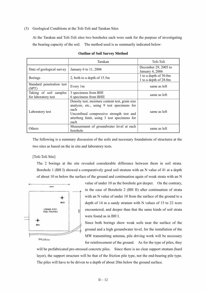
(3) Geological Conditions at the Toli-Toli and Tarakan Sites
At the Tarakan and Toli-Toli sites two boreholes each were sunk for the purpose of investigating
the bearing capacity of the soil. The method used is as summarily indicated below:
Outline of Soil Survey Method
Tarakan Toli-Toli
Date of geological survey January 6 to 11, 2006 December 29, 2005 to January 4, 2006
Borings 2, both to a depth of 15.5m 1 to a depth of 30.0m 1 to a depth of 28.0m
Standard penetration test (SPT) Every 1m same as left
Taking of soil samples for laboratory test
3 specimens from BHI 6 specimens from BHII same as left
Laboratory test
Density test, moisture content test, grain size analysis, etc., using 9 test specimens for each Unconfined compressive strength test and atterberg limit, using 3 test specimens for each
same as left
Others Measurement of groundwater level at each borehole same as left
The following is a summary discussion of the soils and necessary foundations of structures at the
two sites as based on the in situ and laboratory tests.
[Toli-Toli Site]
The 2 borings at the site revealed considerable difference between them in soil strata.
Borehole 1 (BH I) showed a comparatively good soil stratum with an N value of 41 at a depth
of about 10 m below the surface of the ground and continuation again of weak strata with an N
value of under 10 as the borehole got deeper. On the contrary,
in the case of Borehole 2 (BH II) after continuation of strata
with an N value of under 10 from the surface of the ground to a
depth of 14 m a sandy stratum with N values of 15 to 22 were
encountered, and deeper than that the same kinds of soil strata
were found as in BH I.
Since both borings show weak soils near the surface of the
ground and a high groundwater level, for the installation of the
MW transmitting antenna, pile driving work will be necessary
for reinforcement of the ground. As for the type of piles, they
will be prefabricated pre-stressed concrete piles. Since there is no clear support stratum (hard
layer), the support structure will be that of the friction pile type, not the end-bearing pile type.
The piles will have to be driven to a depth of about 20m below the ground surface.
II − 12

[Tarakan Site]
The soils of the site consist of cohesive soils with an
N value of 1 to 8 from the surface of the ground to a
depth of 4 m. The results of the soil tests show a
bearing capacity of the soil of about 60kN/m2 at a
depth of 2m and about 155kN/m2 at a depth of 4m.
Since at least 100kN/m2 is needed for the foundation
of the MW transmitting antenna, it will be necessary
that the foundation depth be at least 4m from the
surface of the ground. On the other hand, since it
is expected that the groundwater level will be no
lower than 0.6m from the surface of the ground,
excavation to a depth of 4m in the foundation work
would require large-scale temporary installations
and drainage, which is not practical. That being the case, just as in the case of the Toli-Toli site, for
the installation of the MW transmitting antenna it will be necessary to do pile driving work to 12m
below the surface of the ground for reinforcement of the ground.
2-2-2-2 The Necessary Equipment for MW Radio Broadcasting Service
The purpose of this Project is to improve MW radio broadcasting systems so as to be able to start
MW radio broadcasting service at the Toli-Toli and Tarakan broadcasting stations. The MW radio
broadcasting system at each of those two broadcasting stations will, as indicated in Fig. 2-1, consist of
a studio system for production of broadcast programs, a system for sending out the programs and a
MW transmitting system for broadcasting of the programs.
Fig. 2-1: The MW Radio Broadcasting System of Toli-Toli and Tarakan Broadcasting Stations
Parabola Antenna
Receiver
Studio Equipment (for production of local programs)
Satellite signal receiving device (for receiving programs from Jakarta)
STL Transmitter
Audio Mixer for Program Transmission
STL Receiver
10kW MW Broadcast Transmitter
(Including Accessory Equipment)
Existing Broadcasting Stations ← → MW Transmitting Stations (to Be Newly Constructed)
PIE
PIE: Program Input and Monitoring Equipment
MW Transmitting
Antenna
MW Transmitting System
ProgramSending SystemStudio System
II − 13

At both the Toli-Toli and the Tarakan broadcasting stations the studio equipment for production
of local programs consists of both professional equipment and consumer equipment. Although the
quantity thereof is not sufficient, it is relatively new, having been procured only 2 years ago, and is
operating satisfactorily. At both broadcasting stations it is possible to continue making use of the
existing studio equipment for production of local programs consisting mainly of music programs that is
presently being implemented (126 hours a week). It will also be possible to continue use of the
satellite receiving equipment for receiving news and other programs from Jakarta since it, too, is
operating satisfactorily. That being the case, it will not be necessary to procure any new studio
equipment or satellite receiving equipment. However, there is presently only one 16-input audio
mixer with one output for switching between local programs and programs (news, etc.) from Jakarta,
which means that it is not possible to use the existing audio mixer for both new MW broadcasting
service and existing FM broadcasting service. Furthermore, the specifications of the existing audio
mixer are not such as to make for stable continuity of programs without a backup power source and an
audio amplifier for amplifying the output to a particular audio level. It is therefore necessary to
procure a new audio mixer for sending out programs that can smoothly switch between local programs
and programs from Jakarta and that has a function of stably sending out program signals to the STL
transmitter equipment.
Moreover, since neither of the two broadcasting stations is equipped with the STL, program input
and monitoring equipment, 10kW MW transmitting system (including accessory equipment), MW
transmitting antenna, VHF communication equipment, etc. that constitute a MW radio broadcasting
system, that equipment will have to be newly procured in this Project as well to start MW radio
broadcasting service.
Table 2-1 below indicates the equipment to be procured in the Project for the MW radio
broadcasting systems as based on the findings of the site survey.
Table 2-1: Equipment Needed for the MW Broadcasting Systems
Equipment Purpose of Use Request or not
New Procurement or Use of the Existing
Equipment Place to Be Installed
Satellite Receiver Receiving programs from Jakarta – Use of the Existing Equipment
Existing Broadcasting Station
Studio Equipment Production of local programs – Use of the Existing Equipment
Existing Broadcasting Station
Audio Mixer for Program Transmission
Switching between local programs and programs from Jakarta and sending the program signal to the STL transmitter
New Procurement Existing Broadcasting
Station
STL Transmitter Sending the program signal to the MW transmitting station
New Procurement Existing Broadcasting Station
STL Receiver Receiving the program signal at the MW transmitting station
New Procurement New MW Transmitting Station
II − 14

Equipment Purpose of Use Request or not
New Procurement or Use of the Existing
Equipment Place to Be Installed
Program Input and Monitoring Equipment
Monitoring of program signal and adjustment of signal level
New Procurement New MW Transmitting Station
10kW MW Broadcast Transmitter (including Cooling Equipment)
Transmission of MW signal
New Procurement New MW Transmitting Station
10kW Dummy Load Apparatus for adjustment of the 10kW MW broadcast transmitter
New Procurement New MW Transmitting Station
10kW Lightning Equipment
Included in the 10kW MW broadcast transmitter
New Procurement New MW Transmitting Station
3-port U-Link Panel Switching of MW broadcast transmitter output between antenna and dummy load
New Procurement New MW Transmitting
Station
45kVA Isolation Transformer
Protection of the equipment from lightning surge
New Procurement New MW Transmitting Station
40kVA Automatic Voltage Regulator (AVR)
Stable supply of electric power
New Procurement New MW Transmitting Station
65kVA Engine Generator Supply of electric power at times of city power failure –
To Be Newly Procured by the Indonesian Side
New MW Transmitting Station
MW Transmitting Antenna System
Radiation of MW radio wave
New Procurement New MW Transmitting Station
Measuring Equipment Equipment maintenance
New Procurement New MW Transmitting Station
VHF Communication Link
Liaison between transmitting station and existing broadcasting station
New Procurement New MW Transmitting Station
2-2-2-3 Basic Design of the Equipment
(1) Basic Conditions for Selection of the Equipment
The equipment for MW radio broadcasting system to be procured in this Project should be
selected to meet the following conditions.
1) Applicable Recommendations and Standards
The recommendations and rules of the following organizations will be applied in view of
their wide international use as norms in the electrical and telecommunications field:
① International Telecommunication Union: Radio Communication Sector (ITU-R)
② International Electrotechnical Commission (IEC)
③ Japan Industrial Standard (JIS)
④ Japan Electronics and Information Technology Industries Association (JEITA)
⑤ International Organization for Standardization (ISO)
⑥ Audio Engineering Society (AES)
II − 15

2) Equipment Operating Environmental Conditions
Ambient air temperature : 15 to 45°C
Indoor temperature : 15 to 45°C
Relative humidity : 97%
Elevation above sea level : Up to 500m
Maximum wind speed : 45m/s
3) Power Supply Voltage and Frequency
Power supply for operation of the equipment: 3-phase, 380V/220V, 50Hz, 4-wire
Commercial power supply voltage fluctuation tolerance: 3-phase, 380V +10/-15%
4) Transmitting Frequency and Transmitter Output
They are to be as follows in accordance with the application made to the ITU:
Transmission Frequency Transmitter Output
Toli-Toli MW Transmitting Station 1377kHz 10kW
Tarakan MW Transmitting Station 1350kHz 10kW
5) Procurement Criteria
① Since ease of operation and maintenance are essential elements in enhancement of
equipment reliability, selection will be made, as far as possible, of equipment that is
manufactured with the same parts and finishing.
② The availability of procurement of spare parts and spare modules should be guaranteed
at least for 10 years. When spare parts and spare modules go out of production,
alternatives with equivalent or better performance should be available.
③ The 10kW MW broadcast transmitters are to be of the solid-state type that does not
use vacuum tubes and adopted the air conditioner cooling system so as to avoid
influence of dust and moisture.
④ Considering the stability of the solid-state type MW broadcast transmitters, standby
MW broadcast transmitters will not be procured. It shall be of a type for which it is
possible to procure spare units such as the power amplifier, Radio Frequency (RF)
exciter, etc. needed in case of trouble.
II − 16

(2) Equipment for MW Radio Broadcasting System
Considering that the Toli-Toli and Tarakan MW transmitting stations will be manned facilities
attended continuously by engineers needed for operation and maintenance as in the case of the
other RRI transmitting stations, all of the basic operations procedures such as starting and
stopping the transmitters, selection and switching of program input and switching back to the
commercial power supply from the emergency power supply when commercial power supply is
failed are in principle to be manual operations. MW radio broadcasting system equipment to be
procured in the Project shall consist of the following: ① 10kW MW Broadcast Transmitter,
② 10kW Dummy Load, ③ 3-port U-link Panel, ④ Program Input and Monitoring Equipment,
⑤ MW Transmitting Antenna System, ⑥ Studio-Transmitter Link (STL), ⑦ Isolation
Transformer, ⑧ Automatic Voltage Regulator, ⑨ Measuring Equipment, ⑩ VHF
Communication Link, ⑪ Audio Mixer for Program Transmission, ⑫ Uninterruptible Power
Supply (UPS), ⑬ Spare Parts, etc. An outline description of each equipment follows.
1) 10kW MW Broadcast Transmitter
In order for it to operate stably over a long time the 10kW MW broadcast transmitter is to
be of full broadcasting specifications using parts with high reliability, and operation of it is
to be manual, with easy operating steps. Furthermore, it is to be of the solid-state type,
which does not need any vacuum tubes, and of the digital modulation method with high
modulation efficiency. Since the solid-state type has high stability and since even if 10%
of the total number of amplifiers of the power amplifier unit malfunction, it is possible to
continue operation without any stoppage, no standby transmitter will be procured.
However, the RF exciter unit consisting of the crystal oscillator, which generates the
transmission carrier wave, and amplifiers that amplify the carrier wave signal to a particular
level is to have a standby with automatic switching in order to avoid, as far as possible,
interruption of broadcasting due to trouble with the RF exciter unit. Furthermore, the
output circuit is to be a band pass filter (BPF) circuit with a lightning resistance function
that consists of combination of a low pass filter (LPF) with the function of eliminating
unwanted high frequencies and a high pass filter (HPF) with the function of attenuating the
lightning surge component.
The advantages of the solid-state type MW broadcast transmitter with the digital modulation
method are as follows:
• Operating cost is reduced by the fact that it does not need vacuum tubes or a
modulation transformer, and also thanks to high overall efficiency.
II − 17

• A operation hindrance doesn’t arise even if about 10% of the total number of the
power amplifier breaks down in power amplification part because it is compensated by
other power amplifiers.
• A protection circuit of the solid-state power amplifier is set up against any unusual
impendence change in the transmitting antenna.
• Maintenance work is made safer by absence of any parts under high voltage.
The following is an outline of the 10kW MW broadcast transmitter to be procured under
the Project.
Station Type of Transmitter
Method of Modulation
Transmitter Output Frequency
Toli-Toli Transmitting Station Solid-state Type Digital modulation 10kW 1377kHz
Tarakan Transmitting Station Solid-state Type Digital modulation 10kW 1350kHz
Adoption of cooling system of the 10kW MW broadcast transmitter by air conditioner will
avoid the influence of moisture and other adverse conditions, thereby making stable
operation for a long time possible. To accomplish cooling system in case the air
conditioner goes out of order the ventilating fan will be provided for control system of
operation by thermostat.
The scope of the air conditioning shall cover the transmitter room, the necessary capacity of
the air conditioner being calculated on the following basis:
① Design conditions
・Design outdoor air temperature conditions
Dry-bulb temperature : 35 °C
Relative humidity : 60%
・ Temperature and humidity conditions inside the transmitter room with air
conditioning
Dry-bulb temperature : 27 °C
Relative humidity : 50%
・Area of transmitter room : 35m2 (5m × 7m)
・Volume of transmitter room : 140m3 (5m × 7m × 4m)
② Calculation of the heat generated by the different equipment ・ 10kW MW broadcast transmitter : 2.5kW
(average degree of modulation of 50%)
II − 18

・ Program input and monitoring equipment
: 0.5kW
・ STL and measuring equipment : 1.0kW
・ Automatic voltage regulator : 0.7kW
・ 3-port U-link panel : 0.3kW
Total : 5.0kW
Total volume of equipment heat : 4,300kcal/H (5kW × 860kcal/H) A
③ Amount of heat intrusion from the building (area × heat reduction rate × actual
temperature difference) ・Quantity of heat from outer wall
(3 surfaces) : 2,000kcal/H
・Quantity of heat from interior walls : 200kcal/H
・Quantity of heat from roof : 2300kcal/H
・Quantity of heat from floor: : 300kcal/H
Total quantity of intrusion of heat: : 4,800kcal/H B
④ Quantity of heat from lighting and an operator: 600kcal/H C
⑤ Degree of leeway in tropical region (10%): 970kcal/H D
The total quantity of heat is 10,670kcal/h (A + B + C + D ), and the required
capacity of the air conditioner is about 11,000kcal/H. Taking into account the operating
efficiency of the air conditioner, coping with the situation when it goes out of order,
maintenance work and other factors, the cooling system should be accomplished by
operation of two air conditioners with a capacity of 5,500kcal/H each.
2) 10kW Dummy Load
A 10kW dummy load is to be installed for maintenance of the 10kW MW broadcast
transmitter. Such a dummy load is for the purpose of checking the MW broadcast
transmitter’s state of operation and electrical characteristics, etc. after switching its output
from the MW transmitting antenna. The load capacity shall be such that the 10kW MW
broadcast transmitter can continuously accomplish 100% modulation. The type of cooling
to be adopted is forced cooling by fan.
3) 3-port U-Link Panel
A coaxial switching equipment (one input and two outputs) will be installed for selecting
II − 19

the output of the 10kW MW broadcast transmitter to the MW transmitting antenna or the
10kW dummy load according to the purpose, i.e. broadcasting, maintenance, etc. It will be
in the form of a 3-port U-link Panel, which for the sake of ease of switching is to be
installed on the wall at the back of the 10kW MW broadcast transmitter.
4) Program Input and Monitoring Equipment (PIE)
There will be installation of a program input and monitoring equipment for automatically
controlling the broadcasted program signal sent from the existing broadcasting station and
for supplying a signal with a stable level to the 10kW MW broadcast transmitter. It will
have such functions as switching inputs, monitoring and adjustment of the input level of the
audio signal, audio monitor, display of transmitter output and degree of modulation, etc. and
will be constituted by the following equipment, which is to be accommodated in a 19” rack.
① Audio Processor
The audio processor is to have the functions of input in the 10kW MW broadcast
transmitter of the program signal sent from the existing broadcasting station after
adjusting it to a certain level and reproducing the same audio quality as FM broadcasts
by compressing and expanding the signal for greater average degree of modulation.
In order to prevent interruption of broadcasting because of trouble, there will be two of
them, one in operation and the other on standby, with manual switching between them.
② FM Receiver
The FM receiver will be used as a backup in case the STL for sending of the program
signal from the existing broadcasting station to the MW transmitting station goes out
of order. Switching between the STL and the FM receiver will be manual.
③ Audio Monitor Switcher and Audio Monitor Speaker
The audio monitor switcher and audio monitor speaker are for making sure that the
broadcasted program signal level and quality is being properly input in the 10kW MW
broadcast transmitter, the audio processor, etc., and the speaker will be equipped with
an amplifier.
④ RF Exciter for 10kW MW Broadcast Transmitter
Since the RF exciter units of the 10kW MW broadcast transmitter, which are to be
redundant, with one in operation and the other on standby, cannot be mounted in the
transmitter itself, it is to be mounted in the PIE rack.
II − 20

5) 10kW MW Transmitting Antenna System
This is a system for radiation of MW broadcast radio waves with an output of 10kW which
consists of an antenna mast, a radial earth system, an antenna tuning unit (ATU), coaxial
cable, dehydrator, obstruction lighting system, etc.
As at the other broadcasting stations the antenna mast with a steel structure is to be of the
type with stays in three directions and an insulated base.
Generally the height of antenna with a transmitter output of 10kW is taken as 0.25 times the
wavelength of the frequency (0.25λ; in the case of 1,000kHz, 0.25λ = 3 × 10⁸/1000000 /4=
75m). But since the frequencies for Tarakan (1350kHz) and Toli-Toli (1377kHz) are both
high frequencies in the MW band, the antenna height would be rather low if designed on the
basis of 0.25λ, which would make for poor radiation effect (a smaller service area than
usual). That being the case, it will be necessary to maximize service area by ① adopting
65m as the antenna height on the basis of the design criterion 0.3λ, which gives optimum
cost-effect ratio considering radiation efficiency and construction cost, ② raising apparent
antenna height by making the upper part of the stays in three directions into an
umbrella-like antenna (top loading) and ③ laying in radial fashion around the antenna at a
depth of 30cm in the ground 120 copper lines (radial earth) with the same length as the
antenna height at intervals of 3° in order to enhance radiation efficiency. The air
navigation obstacle lights are to be installed at the top of the antenna mast besides painting
daytime obstacle signs. The ATU, which is for matching the impedance (50Ω) of the
output of the 10kW MW broadcast transmitter with the impedance of the antenna mast,
which varies with frequency and antenna height, will be installed between the 10kW MW
broadcast transmitter and the antenna mast. The 10kW MW broadcast transmitter and the
ATU will be connected by a 1” 5/8 (39D) coaxial cable (with a length of about 150m) for
the sake of minimizing attenuation of the 10kW MW transmitter output in sending it.
There will also be provision of dehydrator for keeping the coaxial cable filled with dried air
so as to prevent deterioration of transmission efficiency due to the influence of moisture.
Since the findings of the soil surveys at the two sites have shown that both of them have
weak ground, it will be necessary to do pile driving work at both sites for reinforcement of
the ground before the MW transmitting antenna foundation work. Among the possible
types of piles are ① piles made in situ by digging holes in the ground and placing concrete
reinforcement baskets and pouring concrete directly in them, ② square (30cm × 30cm)
concrete piles precast in situ by placing reinforcement baskets in formwork and pouring
concrete in them at the site and ③ round, factory-made prefabricated pre-stressed concrete
II − 21

piles.
The study team compares those methods of pile driving work regarding suitability to the
two sites. Method ① can hardly be said to be suitable from the viewpoints of cost and
quality control considering that large-scale equipment would be needed for prevention of
collapse of the hole walls and for making the concrete. As for method ②, it would entail
lower transportation expense since the piles would be made at the sites, but special care
would have to be taken regarding the work schedule to ensure that proper strength of the
concrete is obtained as well as regarding quality control. On the other hand, although
method ③ would entail higher transportation expense than the others due to fabrication at
the factory, it is outstanding regarding quality assurance, and with it would be possible for
the construction time to be less than half of that for the other methods. That being the case,
the type of piles for ground reinforcement in construction of the MW transmitting antennas
in this Project shall be prefabricated pre-stressed concrete piles. As for the depth to which
the piles are to be driven, it shall be 20m below the surface of the ground in the case of
Toli-Toli and 12m in the case of Tarakan.
Only the foundation under the antenna mast will require piles, direct foundations that do not
make use of piles being sufficient for anchoring the three stays of each mast. However, it
will be necessary to secure an adequate safety margin regarding foundation movement
considering the weakness of the ground.
6) Studio-Transmitter Link (STL)
STL has to be provided for sending the broadcast program signal from the existing
broadcasting station to the MW transmitting station by UHF band. That equipment
consists of the STL transmitter to be installed on the existing broadcasting station side and
the STL receiver to be installed on the MW transmitting station side.
① STL Transmitter Equipment
To be accommodated in a 19” rack in the FM transmitter room of the existing
broadcasting station.
Transmission frequency : 300.75MHz (RRI’s designated frequency)
Transmitting power : 5W (set on the basis of the distance of about 2km between
the existing broadcasting station and the MW transmitting
station)
Transmitting antenna : Yagi antenna (to be installed at the upper section (50m) of the
broadcasting station’s existing 65m self-supporting tower)
II − 22

② STL Receiver Equipment
To be accommodated in a 19” rack in the transmitter room of the MW transmitting
station.
Receiving frequency : 300.75MHz
Signal-to-noise ratio : at least 60dBm
Receiving antenna : Yagi antenna (to be installed at the upper section of
the 50m tower to be newly built by RRI)
7) 40kVA Automatic Voltage Regulator (AVR)
As a result of records over a period of 24 hours of voltage and frequency fluctuation of the
commercial electric power sources of the Toli-Toli and Tarakan broadcasting stations, it has
been confirmed that the voltage fluctuation is +10/-15% of the nominal voltage of 380/220V
at both stations. An automatic voltage regulator (AVR) will therefore have to be installed
to protect the equipment from voltage fluctuation in excess of the stipulated tolerance. It
will be given an input voltage fluctuation range of 380/220V +10/-15%, and its capacity
will be 40kVA considering the total of the capacities of the equipment mentioned below that
is scheduled to be procured under the Project at the MW transmitting station.
Equipment Power source capacity
3-phase / signal phase
10kW MW Broadcast Transmitter 20kVA 3-phase
Program Input and Monitoring Equipment 1kVA Single phase
STL 1kVA Single phase
10kW Dummy Load 1kVA 3-phase
Air Conditioner (1) 5kVA 3-phase
Air Conditioner (2) 5kVA 3-phase
Dehydrator 2kVA Single phase
Obstruction Light 2kVA Single phase
Ventilation Fan 2kVA 3-phase
Measuring Equipment 1kVA Single phase
Total 40kVA
II − 23

8) 45kVA Isolation Transformer
45kVA isolation transformer has to be provided for protection against lightning surge by
attenuation of the lightning surge that penetrates to the equipmentr from the power supply
line. Considering the total capacity of the equipment (40kVA) and a leeway of 10%, its
capacity is set at 45kVA.
9) Measuring Equipment
As the necessary minimum for operation and maintenance of the equipment, an audio signal
generator and distortion meter (for measurement of frequency characteristic, distortion ratio,
S/N ratio, etc.), an oscilloscope (for measurement of degree of modulation, RF output
waveform, etc.) and a resistance attenuator (for adjustment of the transmitter input signal
level) are to be provided. Instead of providing a dedicated rack for them, however, they
will be accommodated in the STL receiver rack.
10) VHF Communication Link
For the sake of smooth accomplishment of daily broadcasting work, a dedicated liaison line
will be installed between the existing broadcasting station and the MW transmitting station.
It will be liaison radio equipment operating on the VHF band allocated to RRI for exclusive
use and will consist of a fixed-station transceiver to be installed at the existing broadcasting
station and a mobile-station transceiver to be installed at the MW transmitting station.
The mobile-station transceiver can be used not only for liaison with the existing
broadcasting station but also for radiated signal confirmation work and for maintenance
work on the MW transmitting antenna. Three mobile-station transceivers will have to be
provided since MW transmitting antenna maintenance work will entail liaison between three
points (the transmitter room, the ATU and the antenna mast).
The main composition of the VHF transceiver and the places where it is to be installed are
as follows:
① Fixed-Station Transceiver (to be accommodated in the STL transmitter rack of the
existing broadcasting station)
• Frequency : 154.5MHz (RRI’s designated frequency)
• Transmitting power : 25W
② Mobile-Station Transceivers (to be placed in the STL receiver rack of the MW
transmitting station)
• Frequency : 154.5MHz (RRI’s designated frequency)
II − 24

• Transmitting power : 5W
11) Audio Mixer for Program Transmission
Audio mixer for program transmission and an audio distribution amplifier have to be
provided for switching between locally produced programs and programs from Jakarta and
for sending the program signal to the STL transmitter. The audio mixer is to be of the
digital type and of professional grade, and it is to have the same number of inputs as the
existing audio mixer, 16 channels. The audio distribution amplifier is to be capable of
4-way distribution of the level-adjusted signal.
12) Uninterruptible Power Supply (UPS)
A backup power source is to be provided so that the equipment to be installed at the existing
broadcasting station can operate even during mains power outages. The UPS, to be
accommodated in the STL transmitter rack, is to have a capacity of 500W to be able to
backup the STL transmitter, the digital audio mixer, the audio distribution amplifier and the
satellite receiving equipment (existing) and a backup time of about 30 minutes.
13) Spare parts
① Consideration to Spare Parts
Selection of spare parts is to be based on the following considerations.
• Spare parts that it will be easy for the RRI personnel to use for replacement
• Mainly the printed circuit boards and units of the main equipment in quantities
such as to ensure operation for at least one year after delivery of the equipment
• Consumables consisting on a priority basis of contactors, relays, parts of
revolving mechanisms, fuses and other things that have to be replaced
periodically.
② Spare Parts to be procured
Since there will be no standby MW broadcast transmitter, to cope with transmitter
failure, essential spare parts to be procured will consist of power amplification (PA)
units, RF driver printed circuit boards, transmitter control printed circuit boards,
analog/digital converter printed circuit boards, AVR control printed circuit boards, etc.
In addition, consumable parts such as fuses, fans, air filters, obstruction lights, magnet
contactors, surge absorbers, choke coils, etc. are also to be procured.
II − 25

14) Installation Materials
There is to be procurement of the different types of power cables and signal lines and the
connectors, special tools and other materials and equipment needed for the equipment
installation work.
• Installation materials : Coaxial cables, Audio cables, Power Cables, Coaxial
Feeder, Sundry installation materials
(3) List of Equipment
Table 2-2 shows the planned equipment to be procured under the Project for the Toli-Toli and
Tarakan broadcasting stations.
Table 2-2: List of Equipment
(Tarakan and Toli-Toli MW Broadcasting Stations: Each 1 set) Equipment Q’ty Main Specifications and Uses
1. 10kW MW Broadcast Transmitter 1 set Frequency: Tarakan 1350kHz Toli-Toli 1377kHz RF Exciter: Main/Standby (Automatic Changeover System)
2 10kW Dummy Load 1 set Load Capacity: 10kW+100% modulation
3 10kW Lightning Protector 1 set Included in the 10kW MW Broadcast Transmitter
4 3-port U-Link Panel 1 set Number of Input :1 Number of Output :2
5 Program Input and Monitoring Equipment 1set
(1) Audio Processor 2 sets Main / Standby (Manual Changeover System)
(2) FM Receiver 1 set Back up for STL Receiving Frequency: 90 to 108MHz
(3) Audio Monitor Switcher 1 set
(4) Audio Jack Panel 1 set
(5) Monitor Speaker 1 set Including Audio Amplifier
(6) NFB Panel 1 set
(7) 19” Rack 1 set
6 MW Transmitting Antenna 1 set
(1) Antenna Mast 1 lot Guy-Wire Type, 65m height
(2) Radial Earth 1 lot 120 Wires, 65m length
(3) Antenna Tuning Unit (ATU) 1 set Including Lightning Protector
(4) Coaxial Cable 1 lot 1-5/8 inch 50Ω, 150m length
(5) Obstruction Light 1 set
(6) Dehydrator 1 set
II − 26

Equipment Q’ty Main Specifications and Uses 7 Studio-Transmitter Link (STL)
7.1 STL Transmitter Equipment 1 set
(1) STL Transmitter 1 set Output Power : 5W Frequency :300.75MHz
(2) UPS (500W) 1 set 30 min Backup for STL Transmitter, Audio Mixer, etc.
(3) NFB panel 1 set
(4) 19” Rack 1 set
(5) Antenna with Coaxial Cable 1 lot Yagi Antenna, Cable: 100m length
7.2 STL Receiver Equipment 1 set
(1) STL Receiver 1 set Frequency: 300.75MHz
(2) NFB Panel 1 set
(3) 19” Rack 1 set
(4) Antenna with Coaxial Cable 1 lot Yagi Antenna, Cable: 100m length
8 40kVA Automatic Voltage Regulation (AVR)
1 set 3-Phase, 380/220V 50Hz Including AC Power Failure Detector such as Under/Over Voltage, Open Phase and Reverse Phase Detector
9 45kVA Isolation Transformer 1 set 3-Phase, 380/220V 50Hz
10 VHF Communication Link 1 set Frequency:154.5MHz
10.1 Fixed Station
(1) VHF Transceiver 1 set Installed in the STL TX Rack
(2) Omni-directional Antenna 1 set High Gain Antenna
(3) Coaxial Cable 1 set 100m length
10.2 Mobile Station
(1) Portable Type VHF Transceiver 3 sets Placed in the STL / Measuring Rack
11 Audio Mixer for Program Transmission 1 set
(1) 16-CH Digital Audio Mixer 1 set Professional Type
(2) Audio Distribution Amplifier 1 set Number of Output: 4
12 Measuring Equipment 1 set
(1) Oscillator with Distortion Meter 1 set Frequency Range : 20Hz to 200kHz, Output +20dBm
(2) Oscilloscope 1 set 200MHz, 2CH
(3) Variable Audio Attenuator 1 set 600Ω, Balanced
(4) Handy Tool set 2 sets Including Soldering sets
13 Cooling Equipment 1 set
(1) Air Conditioner 2 sets Capability: 5500kcal/h
(2) Ventilation Fan 1 set 450mm × 450mm, Thermostat Control Air Quantity: more than 70m3/min. 3-phase 380V, 50Hz
II − 27

Equipment Q’ty Main Specifications and Uses (3) Louver 1 set 1000mm × 1000mm
(4) Dumper 1 set 1000mm × 1000mm, Motor Drive Single phase 220V, 50Hz
(5) Shutter for Ventilation Fan 1 set 450mm × 450mm
(6) Air Filter 1 set 1000mm × 1000mm, including Frame
14 Standard Accessories 1 lot Attached to the Equipment
15 Spare Parts 1 set
(1) Power Amplifier (PA) 5 sets For 10kW MW Broadcast Transmitter
(2) Printed Board of RF Exciter 1 set For 10kW MW Broadcast Transmitter
(3) Printed Board of TX Control 1 set For 10kW MW Broadcast Transmitter
(4) Printed Board of A/D Converter 1 set For 10kW MW Broadcast Transmitter
(5) Printed Board of AVR Control 1 set For 40kVA AVR
(6) Choke Coil for ATU 1 lot For 10kW MW Broadcast Transmitting Antenna
(7) Fuse 1 lot For 10kW MW Broadcast Transmitter, PIE, STL, 40kVA AVR and Dehydrator
(8) Fan 1 pc For 10kW MW Broadcast Transmitter
(9) Surge Absorber 1 lot For 10kW MW Broadcast Transmitter, 45kVA Isolation Transformer and 40kVA AVR
(10) FET for Transistor Power Amplifier 30 pcs For 10kW MW Broadcast Transmitter
(11) Magnet Contactor 1 lot For 10kW MW Broadcast Transmitter and 40kVA AVR
(12) Obstruction Light 3 pcs For MW Transmitting Antenna
(13) Silica Gel 1 set For Dehydrator
16 Installation Materials 1 set
1-5/8” Coaxial Feeder/Cables, Power Cables, Audio Cables Fixing Materials, Installation Tools, etc.
1 lot
2-2-2-4 Basic Design of the Facility
Construction of the transmitter building, the power supply building, the STL tower, etc. for
installation of the equipment to be procured in this Project is to be implemented at the expense of the
Indonesian side. It is necessary that that construction work be done bearing the following matters in
mind and taking into account the data obtained in the soil survey of the two sites. It should also be
noted that some of the incidental facilities work of the transmitter building will be done at the expense
of the Japanese side.
(1) Consistency of the Work to be done by the Indonesian Side and the Japanese Side
For construction of the transmitting station building, the power supply building, etc. the places
II − 28

are to be selected so as not to pose any obstacles to the MW transmitting antenna installation
work, including foundation and laying of the radial earth, that is to be done by the Japanese side
(refer to Fig. 2-4: Toli-Toli Broadcasting Station / Site Layout of MW Radio Transmitting Station,
and Fig. 2-5: Tarakan Broadcasting Station / Site Layout of MW Radio Transmitting Station).
Furthermore, the service entrances are to be wide enough not to give rise to any problems in
bringing in the procured equipment.
(2) Construction of the Transmitter Building and Incidental Facility Work
1) Construction of the Transmitter Building
It is necessary that the transmitter building have a structure with a high degree of air
tightness so as to prevent intrusion of dust from the outside as well as being limited to the
minimal space required for installation and operation of the equipment so as to enhance air
conditioning efficiency. It has to be built in such a way as to meet those conditions and in
accordance with Fig. 2-6: Toli-Toli and Tarakan Broadcasting Stations / Equipment Layout
of MW Radio Transmitting station.
2) Incidental Facility Work
The incidental facility work in the transmitter building necessary for installation of the
procured equipment is divided as indicated below between items for which the Indonesian
side is responsible and items for which the Japanese side is responsible. It is essential that
it be carried out in such a way as not to cause any discrepancies or conflicts between the
work items for which the two sides are respectively responsible (refer to Fig. 2-7: Toli-Toli
and Tarakan Broadcasting Stations / Scope of Works on Incidental Facilities in the
Transmitter Room). It should also be noted that it is necessary that the items for which the
Indonesian side is responsible be completed before commencement of the equipment
installation work that is to be done by the Japanese side.
[ Scope of Work to be carried out by Indonesian Side ]
① Installation of cable ladder
A horizontal cable ladder with a width of 200mm needed for the laying of power
supply lines, audio signal lines, control lines, etc. between the equipment will be
procured and installed in the transmitter room at a height of about 2.5m.
② Installation of Class A grounding
A Class A earth plate (resistance of under 10Ω) needed for the equipment will be
II − 29

installed underground outdoors.
③ Installation of earth terminal box
An earth terminal box needed for connection of the procured equipment earth line will
be installed in the transmitter room. That includes procurement and connection of
the earth line (copper line) from the Class A earth plate installed outdoors to the earth
terminal box.
④ Main power board
A main power board needed for supply of electricity to the equipment will be procured
and installed in the transmitter building. That includes the work of laying the electric
power line from the power supply building. The power capacity should be 65kVA
(380V, 3-phase, 4-wire). (Provision of the wiring from the main power board to the
AVR will be done by the Japanese side.)
⑤ Foundation for Installation of Air Conditioner Outdoor Units
A concrete foundation with a thickness of 100mm (area: 2,200mm × 500mm) needed
for installation of the air conditioner outdoor units for cooling of the equipment is to
be provided. (The Japanese side will procure and install the air conditioner itself.)
⑥ Installation of ventilation fan hood
A hood with an anti-insect screen at the opening of ventilation fan in the transmitter
room shall be procured and installed.
⑦ Installation of canopy
A canopy with a thickness of 50mm (area: 1,600mm × 600mm) is to be procured and
installed above the air intake opening.
⑧ Louver opening work
An opening (1,000m × 1,000m) is to be made for installation of a louver for air intake
(the louver itself will be procured and installed by the Japanese side).
⑨ Air chamber work
An air chamber (area: 900mm × 1,500mm; height: 4,000mm) for removal of dust is to
be set up in the transmitter room.
⑩ Air filter opening work
An opening (1,000mm × 1,000m) needed for installation of the air filter is to be made.
(The air filter itself will be procured and installed by the Japanese side.)
II − 30

⑪ Ventilation fan opening work
An opening (400mm × 400mm) for installation of the ventilation fan is to be made.
(The ventilation fan itself will be procured and installed by the Japanese side.)
⑫ Installation of fluorescent lamps
Lighting fixtures for adequate lighting of each room are to be procured and installed.
[ Scope of Work to be carried out by the Japanese Side ]
① Installation of louver
A louver (1,000mm × 1,000m) is to be installed at the air intake opening made in
advance by the Indonesian side.
② Installation of air filter
A filter frame (1,000mm × 1,000mm) is to be installed in the air chamber.
③ Installation of damper
There is to be installation of a motor-driven damper (1,000mm × 1,000mm) on the
external side of the air filter. Normally the air filter is closed by the damper, shutting
off air from the outside.
④ Installation of ventilation fan with shutter
A ventilation fan with shutter is to be installed as a means of cooling in case the air
conditioner goes out of order. It is to operate automatically, with air intake from the
outside when the motor-driven damper is opened by thermostat.
⑤ Air conditioner
The cooling system is to be by air conditioner for protection of the procured
equipment from dust, moisture, etc. from the outside.
The above work items for which the Japanese side is responsible are to be done at the time
of the equipment installation work.
(3) Construction of Power Supply Building and Procurement of Power Supply Equipment
There is to be procurement of the power supply facilities, including the incoming power receiving
facilities (60kVA) and the emergency generator (65kVA) for use at the time of power outages,
and construction of the building for accommodation thereof. In order to avoid the noise of the
emergency generator it is desirable that the power supply building and the transmitter building be
built at a distance of at least 10m from one another. Switching between the commercial power
source and the emergency generator is to be manually operated by means of a switching board.
II − 31

Connection from the incoming power receiving facilities to the main power board of the
transmitter room is to be by trench (underground).
(4) Construction of STL Self-Supporting Tower
A 50m self-supporting tower for installation of the antenna for the STL receiver for receiving the
broadcast program signal sent from the existing broadcasting station and the antenna for FM
receiver is to be constructed next to the transmitter building. It is appropriate that the height of
installation of the antenna for the STL receiver be at least 40m considering the height of the
coconut trees in the vicinity of the transmitting station. Furthermore, there is to be a horizontal
ladder (about 10m) between the tower and the transmitter building for bringing in the coaxial
cable from the receiving antenna. The receiving antenna, the coaxial cable, etc. are to be
procured and installed by the Japanese side.
2-2-2-5 Coverage Area of MW Radio Broadcasting Service
Although the Toli-Toli and Tarakan broadcasting stations are presently engaged in FM
broadcasting, they have not been able to secure a service area commensurate with transmitting facility
scale because of the fairly mountainous terrain of their respective geographical areas, which is a type
of terrain that does not lend itself to FM broadcasting.
On the other hand, MW broadcasting is propagated as surface waves, which are not influenced all
that much by the terrain, making for good reception even in mountainous area. That means that a
wider service area can be expected with MW broadcasting than with FM broadcasting.
The present FM broadcasting service areas of the two broadcasting stations are compared with
the MW broadcasting service areas that they will have after implementation of this Project in Fig. 2- 2
and Fig. 2- 3, respectively.
Service area is defined in accordance with the ITU-R recommendation as the area within which
the reception field intensity has the values indicated below:
• Reception field intensity within the service area of FM broadcasting:
54dB µ V/m (0.5mV/m)
• Reception field intensity within the service area of MW broadcasting:
60dB µ V/m (1mV/m)
(1) Broadcasting service areas of the Toli-Toli area
1) FM broadcasting service area
Since the southeast, east and northeast parts of Toli-Toli Regency consist of mountainous
II − 32

areas, the present broadcasting service area of the existing 3kW FM transmitter is limited to
the plains of the Ogodide district and the coastal areas of the Baolang, Galang, Bandondo
and North Toli-Toli districts. The population within that broadcasting service area is
estimated at about 110,000, or about 58% of the population of Toli-Toli Regency.
Population of Toli-Toli Regency: 190,579
District Number of Residents District Number of
Residents South Denpai 19,611 Baolang 54,961
North Denpai 12,122 Lanbasio 12,167
Dondo 19,893 Galang 28,860
Ogodide 10,770 North Toli-Toli 22,768
Bandondo 9,427 : Districts covered by FM service
(Source: survey data of the Central Statistics Bureau for 2003)
2) MW broadcasting service area
The broadcasting service area of the Toli-Toli MW transmitting station, which will be
improved by this Project with a 10kW MW broadcast transmitter (1377kHz), will extend
over the entire area of Toli-Toli Regency in Central Sulawesi Province and even the
northern part of Dongara Regency, for an estimated population coverage of about 250,000
people.
Population of Central Sulawesi Province: 2,242,914
Area Surface Area (km2)
Number of Residents Area Surface
Area (km2) Number of Residents
Bangai Island 3,160 150,880 Bagiri Montan Regency 6,231 347,842
Bangai Regency 9,673 284,275 Toli-Toli Regency 4,079 190,579 Morowari Regency 15,490 165,542 Buor Regency 4,043 108,635
Poso Regency 14,433 275,974 Pal Autonomous District 509 281,646
Dongara Regency 10,471 437,541 : Area covered by MW Service
(Source: survey data of the Central Statistics Bureau for 2003)
(2) Broadcasting service areas of Tarakan Region
1) FM broadcasting service area
The present broadcasting service area with the existing 5kW FM transmitter covers all of
Tarakan Regency. But some areas in the eastern and northern parts do not have adequate
II − 33

FM broadcasting reception because of blocking of the radio signal by the mountainous
terrain. It is therefore estimated that in the service area the population with reception is
only about 100,000 (about 77% of the population of Tarakan Regency), centering on the
Central and West Tarakan Districts of Tarakan Regency, instead of all of Tarakan Regency’s
residents.
Population of Tarakan Regency: 124,579
District Number of Residents District Number of
Residents East Tarakan 25,229 West Tarakan 44,885
Central Tarakan 42,885 North Tarakan 11,580
: Districts covered by FM service (Source: survey data of the Central Statistics Bureau for 2003)
2) MW broadcasting service area
The Tarakan MW transmitting station, which will improved by this Project with10kW MW
transmitter (1350kHz) will extend over Tarakan Regency and the Nunukan, Burungan and
Bilau regencies of East Kalimantan Province and an estimated population coverage of
420,000 people.
Population of East Kalimantan Province: 2,609,707
Area Surface Area (km2)
Number of Residents Area Surface
Area (km2) Number of Residents
Nunuka Regency 14,585 82,469 Karutanegara Regency 27,263 424,452
Burungan Regency 18,010 84,438 Samarinda Autonomous District
783 531,912
Tarakan Regency 507 124,579 Bontan Regency 406 106,813
Malinau Regency 42,620 37,237 Balik Papan Regency 749 412,045
Bilau Regency 24,201 123,974 Pasil Regency 14,937 273,495 East Kutai Regency 35,747 151,823 North Pasil
Regency 3,333 117,063
West Kutai Regency 31,628 139,407 : Area covered by MW Service
(Source: survey data of the Central Statistics Bureau for 2003)
The Toli-Toli and Tarakan broadcasting stations chiefly broadcast programs the content of which
is closely related to the local community or region, with programming that meets the desires and
needs of local residents. As mentioned above, the FM broadcasting now being done by those
II − 34

two broadcasting stations is not able to secure a sufficiently wide service area, which means that
the benefit of such FM broadcasting can be enjoyed only by those living not too far from the
stations. Residents who do not have reception of that FM broadcasting are able to receive only
broadcasts from Malaysia and the Philippines. Although they are Indonesian, they do not have
access to Indonesian information, and that has given rise to an information gap within the region.
But as a result of provision of those broadcasting stations with MW transmission facilities, the
broadcasting service areas of those stations will be enlarged, increasing the number of residents
that can receive RRI’s radio broadcasts from about 110,000 to about 250,000 people in the
Toli-Toli region and from about 100,000 to about 420,000 in the Tarakan region.
Fig 2-2:
Fig. 2-3:
Fig
Fig
The MW and FM Broadcasting ServiceAreas of the Toli-Toli BroadcastingStation
. 2- 2
. 2- 3
II − 35
The MW and FM Broadcasting ServiceAreas of the Tarakan BroadcastingStation

2-2-3 Basic Design Diagrams
Fig. 2-4 : Toli-Toli Broadcasting Station / Site Layout of MW Radio Transmitting Station
Fig. 2-5 : Tarakan Broadcasting Station / Site Layout of MW Radio Transmitting Station
Fig. 2-6 : Toli-Toli & Tarakan Broadcasting Station / Equipment Layout of MW Radio Transmitting
Station
Fig. 2-7 : Toli-Toli & Tarakan Broadcasting Station / Scope of Works on Incidental Facilities in the
Transmitter Room
Fig. 2-8 : Toli-Toli Broadcasting Station / Floor Layout of FM Transmitter Room
Fig. 2-9 : Toli-Toli Broadcasting Station / Floor Layout of Continuity Studio
Fig. 2-10 : Tarakan Broadcasting Station / Floor Layout of FM Transmitter Room
Fig. 2-11 : Tarakan Broadcasting Station / Floor Layout of Continuity Studio
Fig. 2-12 : Toli-Toli & Tarakan Broadcasting Station / Overall Block Diagram of MW Broadcasting
System
Fig. 2-13 : Toli-Toli & Tarakan Broadcasting Station / Block Diagram of MW Transmitting System
Fig. 2-14 : Toli-Toli & Tarakan Broadcasting Station / Block Diagram of 10kW MW Transmitter
Fig. 2-15 : Toli-Toli & Tarakan Broadcasting Station / Block Diagram of 40kVA AVR
Fig. 2-16 : Toli-Toli & Tarakan Broadcasting Station / External View of Program Input & Monitoring
Rack and STL/Measuring Rack
Fig. 2-17 : Toli-Toli & Tarakan Broadcasting Station / Elevation of 65m MW Transmitting Antenna
Fig. 2-18 : Toli-Toli Broadcasting Station / Block Diagram of MW Broadcast Program Transmission
Fig. 2-19 : Tarakan Broadcasting Station / Block Diagram of MW Broadcast Program Transmission
Fig. 2-20 : Toli-Toli Broadcasting Station / Block Diagram of Power Supply (Broadcasting Station
Side)
Fig. 2-21 : Tarakan Broadcasting Station / Block Diagram of Power Supply (Broadcasting Station
Side)
Fig. 2-22 : Toli-Toli Broadcasting Station / Elevation of 65 m Self-Supporting Tower
Fig. 2-23 : Tarakan Broadcasting Station / Elevation of 65 m Self-Supporting Tower
II − 36

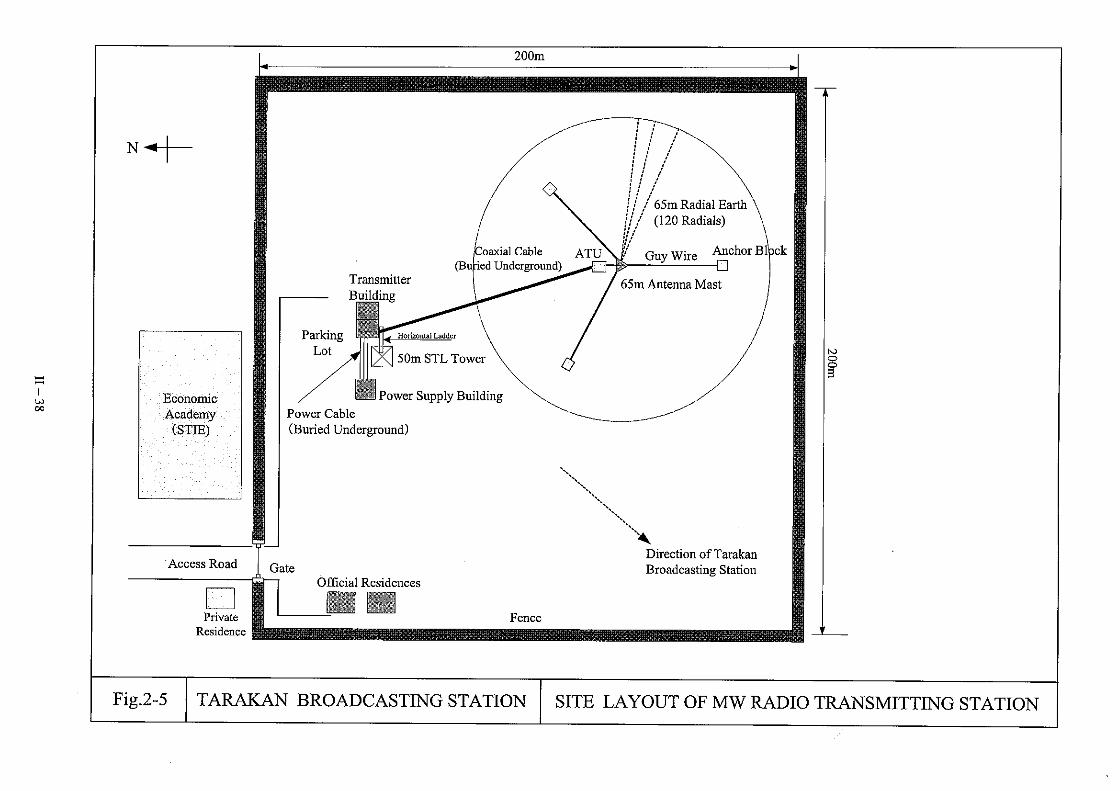


2-2-4 Implementation Plan
2-2-4-1 Implementation Policy
(1) Implementation Setup
1) Implementation Procedure
This Project will be implemented according to the framework of the grant aid scheme of the
Government of Japan. Therefore, it shall be implemented, following cabinet decision by
the Government of Japan and the Exchange of Notes (E/N) between the governments of
both countries. Following the E/N, the project implementing agency shall conclude an
agreement with the consultant, which shall then enter into the detailed design for the project
components.
Tender documents prepared by the consultant shall be distributed to prospective tenderers
after approval has been obtained from the project implementing agency and the Government
of Japan and the announcement of tender. The tender works for the Project up to the
signing of the contract shall be implemented in Japan. Meanwhile, concerning the
consultant agreement, it is normal to be concluded in Indonesia.
The contractor decided by the tender shall start manufacturing of the equipment and carry
out the installation work of the equipment to the buildings constructed by Indonesia side.
Until the total completion of these works, RRI must consolidate the operation and
maintenance setup and secure the necessary operating budget and manpower.
2) Role of Each Organization in Project Implementation
The roles and important duties of each organization concerned with the project
implementation are summarized in the following paragraphs.
① Project Implementing Agency
The project implementing agency is Radio Republic Indonesia (RRI) under the
supervision of the Ministry of Communications and Information Technology
(KOMINFO). In order to ensure full understanding of the grant aid system and the
smooth implementation of the Project, RRI must maintain close communications with
all related agencies on the Indonesian and Japanese sides and appropriately coordinate
work in all stages of the Project. Moreover, the KOMINFO (the responsible
Ministry) should make the utmost effort in order to secure sufficient budget for
carrying out the scope of works of Indonesia side and enabling RRI to conduct
appropriate operation and maintenance.
II − 57

RRI and KOMINFO should place emphasis on implementing the following items:
• Securing of budget for the scope of works done by Indonesia side and
formulation of the schedule and implementation of the scope of works that
complies with the overall project schedule;
• Identification and handling of all the procedures that need to be followed on the
Indonesian side during the project period; and
• Understanding and arrangement of permits and authorizations connected with the
Project, and provision and coordination of relevant information with the
consultant
② Consultant
Following the Exchange of Notes (E/N) between the governments, RRI shall conclude
a consultant service agreement for detailed design and supervision works with the
Japanese consultant, and the Government of Japan shall verify this agreement.
Following the verification, the consultant shall implement survey and discussions
concerning the contents of the detailed design with RRI, and then shall commence the
detailed design according to this basic design study report. The consultant shall
compile the findings of the detailed design into the design drawings and specifications,
and shall also prepare the instructions to tenderer, draft contracts, general contract
conditions and other tender related documents and obtain approval thereof from RRI.
In the tender stage, the consultant shall act on behalf of RRI in carrying out all tender
affairs up to the signing of contracts between RRI and the contractor including
announcement of tender, distribution of tender documents, answer to questionnaire,
opening of tenders, contract negotiations, and so on. Moreover, in the supervision
stage of the Project, the consultant shall implement all supervisory service from the
procurement of the equipment through to installation, adjustment of the equipment and
handing over. In this Project, one of the most important tasks of the consultant is to
act as a coordinator on the interface and work schedule between the works done by
Indonesian side and the equipment installation work done by Japanese side.
③ Contractor
The contractor shall be selected from among Japanese general trading companies that
possess ample experiences in this field. These conditions of tenderers’ qualifications
shall be stipulated in the tender announcement. The contractor shall be decided by
the open tender. The contractor shall complete procurement and installation of the
equipment that comply with the specifications prepared by the consultant within the
II − 58

contract periods. When handing over the equipment, the contractor shall submit
completion drawings and adequate maintenance manuals, and furthermore shall be
responsible for after-sales service such as supply of spare parts, appropriate response
in case of equipment failure, etc.
(2) Need for Sending Technical Personnel From the Manufacturers
Most of the broadcasting equipment to be introduced in this Project will be dismantled, if
necessary, after manufacturing in Japan or a third country and then transported to the site. After
it arrives at the site, it will be necessary to restore it to its original condition through assembly
work and then undertake mounting and adjustment work. In view of the fact that such
dismantling and reassembly work is based on the equipment manufacturer’s special know-how,
that a high technical level is required for adjustment and testing after mounting and that there is a
whole series of steps that have to be taken after the installation/mounting work before the
equipment can be accepted, including explaining of the operation method of the different
equipment, training and quantity inspection, sending of technical personnel for that from the
manufacturers is indispensable. Furthermore, since MW transmitting antenna installation work
requires special technology, sending of technical specialists is necessary for it as well. The
technical personnel that have to be sent, their number and the time for which they are sent are to
be set as the minimum that is necessary, and in the installation/mounting work they are also to
strive for accomplishment of technology transfer to the RRI’s technical staff and other local
technical personnel.
Since the technical personnel of the Toli-Toli and Tarakan broadcasting stations are already
basically versed in broadcasting equipment operation and maintenance techniques, there are no
technical problems regarding maintenance and upkeep. However, in view of the fact that they
are not familiar with operation and maintenance of the latest equipment based on digital
technology, after completion of the installation/mounting work about 15 days of guidance in
operating and maintenance methods mainly concerning the MW broadcast transmitters procured
in this Project will be provided to the technical personnel of the Toli-Toli and Tarakan
broadcasting stations by specialists who are sent for that purpose.
2-2-4-2 Implementation Conditions
(1) Matters Regarding Natural Conditions That Require Attention
As a result of study of the rainfall, air temperature, humidity and wind speed conditions and
frequency of seismic activity in the vicinity of the sites, it has been determined that there are no
II − 59
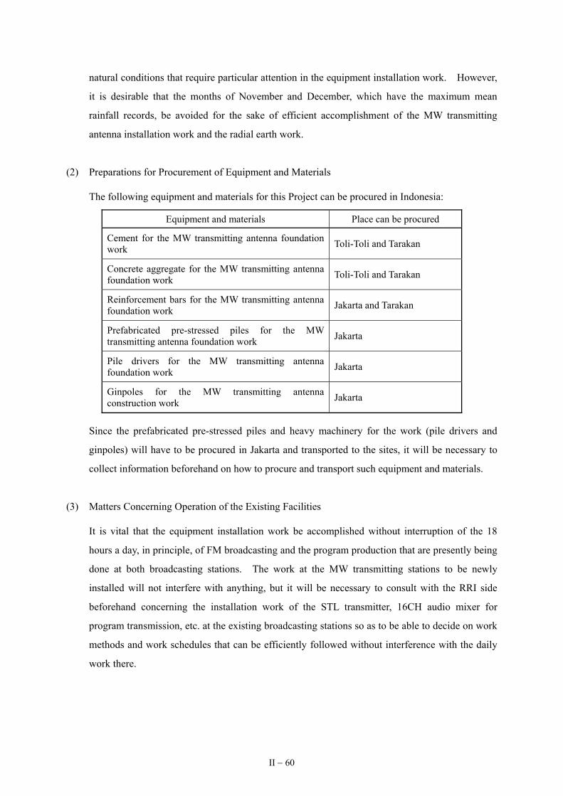
natural conditions that require particular attention in the equipment installation work. However,
it is desirable that the months of November and December, which have the maximum mean
rainfall records, be avoided for the sake of efficient accomplishment of the MW transmitting
antenna installation work and the radial earth work.
(2) Preparations for Procurement of Equipment and Materials
The following equipment and materials for this Project can be procured in Indonesia:
Equipment and materials Place can be procured
Cement for the MW transmitting antenna foundation work Toli-Toli and Tarakan
Concrete aggregate for the MW transmitting antenna foundation work Toli-Toli and Tarakan
Reinforcement bars for the MW transmitting antenna foundation work Jakarta and Tarakan
Prefabricated pre-stressed piles for the MW transmitting antenna foundation work Jakarta
Pile drivers for the MW transmitting antenna foundation work Jakarta
Ginpoles for the MW transmitting antenna construction work Jakarta
Since the prefabricated pre-stressed piles and heavy machinery for the work (pile drivers and
ginpoles) will have to be procured in Jakarta and transported to the sites, it will be necessary to
collect information beforehand on how to procure and transport such equipment and materials.
(3) Matters Concerning Operation of the Existing Facilities
It is vital that the equipment installation work be accomplished without interruption of the 18
hours a day, in principle, of FM broadcasting and the program production that are presently being
done at both broadcasting stations. The work at the MW transmitting stations to be newly
installed will not interfere with anything, but it will be necessary to consult with the RRI side
beforehand concerning the installation work of the STL transmitter, 16CH audio mixer for
program transmission, etc. at the existing broadcasting stations so as to be able to decide on work
methods and work schedules that can be efficiently followed without interference with the daily
work there.
II − 60

(4) Ensuring Safety During the Work
During the period of the installation work, the contractor and the consultant are to obtain the
latest information on the security situation in the regions in question and strive to ensure safety at
the project sites and in movement between them. In cases in which it is judged that safety
cannot be ensured, the two sides—the Embassy of Japan and the JICA office in Indonesia and the
Japanese Ministry of Foreign Affairs and JICA Headquarters in Japan on the Japanese side and
the Ministry of Communications and Information Technology and the RRI on the Indonesian
side—are to discuss the situation and decide measures to be taken.
Also this Project includes the installation work of the MW transmitting antennas with a height of
65m and the work of mounting the STL antennas and VHF communication antennas on the 50m
self-supporting towers to be constructed by the Indonesian side. At the time of such work it will
be necessary to be extremely careful to ensure safety in work at heights, including obligatory use
of helmets and safety belts, placement of signs at the bottom of the towers during the work that
indicate that work at heights is taking place above, assigning of safety monitoring personnel on
the ground and suspension of the work during rain or strong winds.
2-2-4-3 Scope of Works
Table 2-3 below lists the items for which the Government of Japan and the Government of
Indonesia will be responsible, respectively, in case of implementation of this Project on the basis of
Japanese grant aid assistance.
Table 2-3: Table of Items for Which the Governments of the Two Countries Will Be
Respectively Responsible
Items of responsibility Japan IndonesiaObtaining of the MW transmitting frequencies for Toli-Toli and Tarakan Preparation of the land of the sites for the Toli-Toli and Tarakan MW Transmitting Stations
Procurement, transport and installation of the MW broadcasting system equipment and guidance of operation after the installation work
(in connection with construction of the Toli-Toli and Tarakan MW transmitting station buildings)
Construction of the MW transmitter buildings Procurement and installation of the cable ladders Provision of Class A earth facilities Procurement and installation of the earth terminal boxes Procurement and installation of the main power boards Concrete foundations for installation of the air conditioner outdoor units Procurement and installation of the ventilation fan hoods
II − 61

Items of responsibility Japan IndonesiaOpenings for louvers Installation of air chambers Openings for air filter Openings for ventilation fans Procurement and mounting of fluorescent lamps Procurement and mounting of louvers Procurement and mounting of air filters Procurement and installation of ventilation fan dampers Procurement and mounting of ventilation fans with shatter Construction of power supply building Procurement of 65kVA emergency generators Preparation of access roads Preparation of parking space Construction of official residences Construction of the 50m self-supporting towers Procurement and installation of horizontal ladders Work for bringing in commercial power supply Work for laying water supply lines Obtaining of all permits and authorizations required by law in Indonesia Ensuring safety during the period of the work Arrangement of tax exemption for the imported equipment Issue of authorizations to pay (A/P) and payment of bank commissions for issue therefore and changes in them
Appropriate and efficient maintenance and operation of the procured equipment in this Project
Meeting of any other obligations on the part of the recipient country the assistance that are specified in the Exchange of Notes
2-2-4-4 Consultants Supervision
(1) Basic Concept of Supervision
To ensure the smooth execution of the Project, the consultant shall organize a project team to
manage the implementation of detailed design and supervision works based on the purport of the
basic design. The basic concept of the supervision work shall be as follows.
1) Carry out fine-tuned adjustments to ensure that no discrepancies arise on the equipment
installation work, and make the utmost effort to ensure completion of the works on
schedule.
2) Appropriately report on work progress to related organizations in both countries to ensure
there are no discrepancies in their understanding of work status. Moreover, give prompt
II − 62

responses and advice to inquiries from the contractor.
3) Be prepared to offer technical transfer to officials on Indonesia side in order to realize
greater effects of the grant aid. Moreover, always be ready to offer adequate and
appropriate explanations concerning not only the design concept of the equipment but also
execution methods and technology, etc.
(2) Contents of Consultant’s Supervision
The contents of the supervision work to be implemented by the consultant are as follows:
1) Contract-related Service
The consultant shall implement such contract-related services as: preparation of detailed
design and tender documents, handling of tenderers from announcement of tender through
to opening of tenders, evaluation of tenders and selection of the contractor, holding of
contract negotiations, and witnessing of the contract, etc., and report on the progress and
results of such events to RRI at appropriate points.
2) Examination of Items Submitted by the Contractor
The consultant shall review execution plans, work schedules, working drawings, shop
drawings, technical materials and samples, etc. submitted by the contractor and approve
them upon confirming their compliance with design drawings and specifications, etc.
3) Supervision of Work
The consultant shall dispatch supervisors to the project sites at appropriate points during the
execution period to supervise whether the works are being implemented according to the
specifications and drawings and to give the necessary instructions. Moreover, the
consultant shall constantly supervise in detail the work progress and offer appropriate
advice and guidance to the contractors. The consultant shall prepare monthly reports of
work progress and inform the parties related thereto.
4) Cooperation Regarding Payment Approval Procedures
Concerning contract fees to be paid to the contractor during and after the works, the
consultant shall examine all requests for payment, etc. that are submitted by the contractor,
and issue the necessary certificates.
II − 63

5) Inspections and Witnessing
The consultant shall implement inspections of the equipment at the plant before shipment,
and witness various tests implemented at sites such as acceptance inspection on completion
of the work. The consultant shall give approval when the inspection results comply with
specifications and design documents, or issue proper instructions to the contractor if
nonconformities are found. Test results shall be compiled into the monthly reports and fed
back to the related organizations.
6) Assistance of Handing Over Procedures
In addition to compiling the acceptance inspection reports, the consultant shall review and
approve spare parts and equipment manuals and maintenance manuals, etc. that are handed
over by the contractor and provide pertinent advice to RRI concerning the operation and
maintenance of the equipment.
(3) Supervisory Personnel Assignment Plan
Although this Project is one for provision of equipment, it includes the foundation work for the
MW transmitting antennas and the pile driving work for reinforcement of the ground.
Furthermore, the transmitter building is technical structures that require close overseeing of the
installation work. The supervision of the work by the consultant must be accomplished with
constant awareness of the overall situation of the work and close liaison with the Indonesian
governmental organizations concerned and the contractor so as to be able to ensure observance of
the work schedule. For that, sending of a supervisor who is assigned to stay for the whole
period of the foundation work for the MW transmitting antennas is indispensable. Furthermore,
one supervisor at a time is to be sent for the MW transmitting antenna installation work and the
MW transmitter equipment installation work in spot fashion when needed. The criteria for
selection of such supervisory personnel are plentiful experience and appropriate technical
judgment as well as broad vision and good adjustment capability.
2-2-4-5 Quality Control Plan
The consultant shall carry out quality control during the project execution stage based on the
purport of the basic design. The JIS definition of quality control, i.e. ‘the structure of means for
economically producing goods or services of quality that complies with customer requirements’, shall
be adopted as the basic line of the project execution. The consultant will provide the contractors with
appropriate guidance to entirely assure the quality of the equipment procured in this Project, by
II − 64

carrying out detailed surveillance on all the stages of the Project from the tender, installation,
adjustment and inspection, and completion and handover. Among the all processes, the following is
five important points in terms of quality control:
• Tendering
• Manufacturing of equipment
• Shipping and transportation
• Installation work in Indonesia
• Adjustment, acceptance test and handover of the equipment
The priority issues at each of the above five stages are summarized below.
1) Tendering
At the tendering stage, the consultant will examine in detail if the systems proposed by
tenderers comply with the specifications provided for under the tender documents.
2) Equipment manufacturing stage
Reviewing of the technical information materials, manufacturing drawings, samples, etc.
submitted by the contractor and confirming in detail conformity with the written
specifications. Confirmation of the functions and electrical characteristics of the 10kW
MW transmitting equipment, which consists of products manufactured by special order, in
the presence of the consultant at the time of inspection at the plant before shipment and
close review of the degree of completion of the system.
3) Shipping and Transportation
The consultant entrust the following verifications to a reliable, third-party inspection
organization, in prior to shipment of the equipment.
• Comparison of the contract equipment list with the shipping documents
• Comparison of the shipping documents with the equipment
• Issuance of inspection certificates
Furthermore, in the aspect of transportation, the consultant will confirm if the transportation
route is appropriate, and if necessary measures are in place for minimizing a possibility of
accident during transportation, and provide adequate recommendation on rerouting, etc. as
necessary.
II − 65

4) Installation Work in Indonesia
During the installation work stage, it is no exaggeration to say that execution of safe,
accident-free works is the ultimate key to successful installation work of the equipment.
The consultant will provide guidance from this standpoint after prior confirmation of the
details of work plan proposed by the contractor, such as planning an unforced schedule,
allocating appropriate staff, work procedures, etc., so that the works will be smoothly
carried out without any accident.
5) Adjustment, Acceptance Test and Handover of the Equipment
After the installation, adjustment and inspection of the equipment are completed, the
consultant will confirm if the original functions and electric characteristics of the equipment
are reproduced, by comparing the test data taken at the sites and at the factory before
shipment. Further, the consultant will provide the contractor with sufficient guidance on
the handover of the equipment, suggesting, for example, that the contractor confirm the
numbers on the contract equipment list and prepare a detailed spare parts list, so as to
transfer adequate technical information to the Indonesian side.
2-2-4-6 Procurement Plan
(1) Equipment Procurement Plan
In the grant aid projects, qualification as the source of procurement is in principle limited to
Japan and the country receiving the aid, but the MW broadcasting equipment to be procured in
this Project consists of the latest types of electronic parts, which are not produced in Indonesia.
Furthermore, RRI has full confidence in Japanese products because of their stability and
reliability of performance and sureness of supply as well as excellent follow-up system
(particularly the fact that for Japanese made equipment it is guaranteed that spare parts will be
supplied for at least 10 years). Besides that, the main part of the existing equipment consists of
Japanese products. That being the case, the equipment introduced in this Project will, in
principle, be Japanese products.
However, among the equipment in this Project there is some that is no longer produced in Japan
and some for which Japanese products might not be the most appropriate in comparison of
functions, performance and price. For instance, Indonesian regulations require that the STL for
sending broadcast programs from the existing broadcasting station to the MW transmitting station
to be newly built use the UHF frequency band. In aid up to now (yen loan aid) Japanese
products have been procured for the STL in UHF frequency band, but in the meantime in Japan
II − 66

the frequency band for STL has changed to SHF, which would make it extremely difficult now to
procure STL in UHF band from Japan. That being the case, it is necessary to consider products
of OECD countries such as the U.S., Canada or European countries for the STL. Table 2-4
gives a list indicating the likely countries of production of the main equipment in this Project.
Table 2-4: List of Main Equipment and Countries of Production Thereof
Country of Manufacture Equipment
Indonesia Japan Other
CountryReasons for Choice and Remarks
10kW MW broadcast transmitters and accessory equipment
Assured quality and performance, sureness of supply and use by RRI in the past
MW transmitting antenna Assured quality and performance, sureness of supply and use by RRI in the past
Program input and monitoring equipment
Assured quality and performance, sureness of supply and use by RRI in the past
STL Assured quality and performance and use by broadcasting stations in Indonesia and elsewhere in the world in the past
Measuring equipment Assured quality and performance, sureness of supply and use by RRI in the past
VHF communication link Assured quality and performance
Digital audio mixer Assured quality and performance, sureness of supply and use by RRI in the past
Audio distribution amplifier Assured quality and performance, sureness of supply and use by RRI in the past
Legend :Main country of manufacture :Possible country of manufacture
Before shipmen of the equipment, the Contractor shall make up the broadcasting system with the
procured equipment and confirmed function of the system in Japan.
(2) Equipment Transportation Plan
The transportation route for the procured equipment in this Project will be as follows: From
Japan to Jakarta or Surabaya by ocean vessel (container ship); accomplishment of customs
clearance at the port of arrival and transshipment to home-waters vessel for transportation to
Toli-Toli and Tarakan; and after unloading at the port of Toli-Toli or Tarakan transportation to the
site by truck. The necessary transportation time will be about 45 days as per the breakdown by
means of transportation given below.
• For the Toli-Toli site
• Japan to port of Jakarta or Surabaya … About 20 days, by 40 feet container ship
II − 67

• Unloading and customs clearance at port of Jakarta or Surabaya …About 10 days
• Port of Jakarta or Surabaya to port of Toli-Toli … About 14 days, by 20 feet
container ship (40 feet container ship cannot get to Toli-Toli port.)
• Port of Toli-Toli to the Toli-Toli site … About 1 day, by truck
• For the Tarakan site
• Japan to port of Jakarta or Surabaya … About 20 days, by 40feet container ship
• Unloading and customs clearance at the port of Jakarta or Surabaya … About 10 days
• Port of Jakarta or Surabaya to port of Tarakan … About 14 days, by 40 feet container
ship
• Port of Tarakan to the Tarakan site … About 1 day, by truck
The documents that will be needed for the import formalities are as follows:
① Commercial invoice ② Packing list
③ Insurance policy ④ Certificate of origin
⑤ Original bill of lading ⑥ Letter of approval of consignee
⑦ Duty exemption authorization (document to be arranged by RRI)
A matter to which attention must be paid as regards transportation is the need for the
implementing agency to accomplish “State Project Registration” (DIPA formalities) after
conclusion of the E/N of the Project. If those formalities have not been taken care of, it will not
be possible to get the duty exemption confirmation needed for customs clearance, and customs
clearance will be delayed, which could result in major delay in implementation of the Project. It
is therefore necessary for the Ministry of Communications and Information Technology to
accomplish the DIPA formalities by the time of arrival of the equipment at the port of import.
2-2-4-7 Soft Component
The best way to ensure that proper operation and maintenance methods are acquired for the MW
broadcast transmitters to be provided in this Project is to provide guidance in use of the equipment that
is actually installed. Since operating and maintenance methods have been simplified in the solid-state
type MW broadcast transmitters developed on the basis of technological progress, large-scale training
is not necessary. That being the case, there is no need to accomplish operation and maintenance
guidance for the equipment to be procured under the Project on the basis of a soft component and
technical assistance, and it is considered that it will suffice to provide 15 days of initial operating and
maintenance guidance by a specialist sent by the contractor after completion of the installation work.
II − 68

2-2-4-8 Implementation Schedule
The following is the implementation schedule of this Project. (Refer to Table 2-5.)
(1) Detailed design and tendering : 4 months
(2) Equipment procurement / installation works : 13 months
The total period needed for completion of the Project is 17 months.
Table 2-5: Work Implementation Schedule
1 2 3 4 5 6 7 8 9 10 11 12 13
Det
aile
d de
sign
MW
tran
smitt
ing
ante
nna
Equi
pmen
t pro
cure
men
t and
inst
alla
tion
MW
tran
smitt
ing
equi
pmen
t
Site survey
Design work in Japan
Approval of tender documents
Services on tendering
Manufacture and procurement
Transportation
Pile driving work for reinforcement of the ground at the Toli-Toli MW transmitting station
MW transmitting antenna foundation workand installation wok at Toli-Toli MW
transmitting station
Pile driving work for reinforcement of theground at the Tarakan MW transmitting station
MW transmitting antenna foundation work and installation
work at Tarakan MW transmitting station
Manufacture and procurement
Transportation
Installation / adjustment work at theToli-Toli MW transmitting station
II
Installation / adjustment work at the Tarakan MW transmitting station
: W
− 69
Operating and maintenance guidance at theToli-Toli and Tarakan broadcasting stations
ork in Indonesia : Work in Japan

2-3 Obligations of Recipient Country
The matters for which the Indonesian side will be responsible if this Project is implemented on
the basis of Japanese government grant aid are the following:
(1) Obtaining of the MW transmitting frequencies for the Toli-Toli and Tarakan broadcasting stations
For establishment of a new MW radio station (application for new allocation of frequency),
moving of the location of a radio station, changing the frequency, increasing radiation power, etc.
the ITU requires that the formalities stipulated by the Final Acts of the Regional Administrative
LF/MF conference (Regions 1 and 3) held at Geneva in 1975 be carried out.
Since the Toli-Toli and Tarakan broadcasting stations have not been allocated MW broadcasting
frequencies, in connection with new establishment of MW radio transmitting stations at those two
broadcasting stations, they have to obtain new frequencies from the ITU.
The situation regarding the progress that has been made by the Indonesian side in obtaining those
frequencies is as described below.
First they made a list of candidate frequencies—the 4 frequencies 1350kHz, 1260kHz, 1305kHz
and 1395kHz for Tarakan and the 4 frequencies 1287kHz, 1332 kHz, 1377kHz and 1422kHz for
Toli-Toli. Then on September 12 2005, the Ministry of Communications and Information
Technology (its department that manages frequencies) applied to the ITU for the frequencies
indicated below as frequencies among those candidate frequencies with little interference with
broadcasting from other countries.
Site Frequencies Transmitting Power
1287kHz 10kW Toli-Toli
1377kHz 10kW
Tarakan 1350kHz 10kW
These frequencies have officially notified to the all countries by the ITU Circular (BRIFIC 2562,
GE 75/113) on February 7 2006. After due date of lodging the objection to the circular on May
30 2006, these frequencies would be officially allocated.
(2) Preparation of the land of the transmitting station sites
1) Toli-Toli transmitting station
The plans called for leveling and banking on 4 hectares of marshland (elevation above sea
level of 2m) located about 5km southwest of the town of Toli-Toli and about 2km from the
coast to use as the transmitting station site. Because of such low elevation of 2m above
II − 70

sea level, above 1 m of filling was necessary. The Toli-Toli regional government began
preparation work of the land in November 2005 and already finished such work in February
2006. A paved access road to the transmitting station (about 350 m long) was also
improved by the regional government. It spent Rp 4,000,000,000 for the work.
2) Tarakan transmitting station
The plans call for preparation of 4 hectares of woodland behind the economics college
(STIE) to use as the site of the transmitting station. Considerably large-scale work (felling
of trees and filling) will be needed to obtain a level ground since the whole site consists of
undulating ground with a difference in elevation of about 10m. The Tarakan regional
government began the land preparation work in March 2006 and will complete such work
by the end of June 2006. The regional government’s budget allocation for the work is Rp
6,224,000,000.
(3) Construction of transmitting station buildings
Construction of a transmitter building, a power supply building, an STL tower, etc. is necessary at
the Toli-Toli and Tarakan MW transmitting stations, the budget for that being as follows:
1) Toli-Toli transmitting station
Construction of 70m2 Transmitter Building Rp 140,000,000
Construction of 36m2 Power Supply Building Rp 72,000,000
Construction of Access Road (300m × 3m2) Rp 270,000,000
Construction of Parking Lot (200m2) Rp 60,000,000
Construction of 2 Officinal Residences (35m2 × 2) Rp 105,000,000
50m Self-Supporting Tower for STL Rp 700,000,000
Procurement of 65kVA Emergency Engine Generator (1 set) Rp 285,000,000
65kVA Power Supply Construction Rp 70,000,000
Water Supply Works Rp 100,000,000
TOTAL Rp 1,802,000,000
(The Toli-Toli regional government is presently constructing the access road.)
II − 71

2) Tarakan transmitting station
Construction of 70m2 Transmitter Building Rp 140,000,000
Construction of 36m2 Power Supply Building Rp 72,000,000
Construction of Access Road (300m × 3m2) Rp 270,000,000
Construction of Parking Lot (200m2) Rp 60,000,000
Construction of 2 Official Residences (35m2 × 2) Rp 105,000,000
50m Self-Supporting Tower for STL Rp 700,000,000
Procurement of 65kVA Emergency Engine Generator (1 set) Rp 285,000,000
65kVA Power Supply Construction Rp 70,000,000
Water Supply Works Rp 100,000,000
TOTAL Rp 1,802,000,000
RRI estimated those construction costs (total of Rp 3,604,000,000 (about 43.2 million yen) for
the two transmitting stations) on the basis of its past experience and applied to the National
Development Planning Agency (BAPPENAS) for approval in June 2005. The necessary
construction cost will allocate to RRI as a part of the budget for national projects (DIPA) in April
2006. The construction schedule for the transmitting stations is given below.
2006
1 2 3 4 5 6 7 8 9 10 11 12
Tender for selection of the consultant for design of the station buildings and tower
Design of the station buildings and tower
Tender for selection of the contractor for construction of the station buildings and tower
The construction work
(4) Securing of space for the equipment and material storage areas
It is necessary to secure the space for temporary storage of the imported equipment and
installation materials.
(5) Obtaining of the construction permits for the transmitting station buildings and MW transmitting
antenna
Indonesia has restrictions and an authorization system concerning building construction that is
II − 72

prescribed by law. It will therefore be necessary in this Project for the Indonesian side to apply
for and obtain in time authorizations for the construction of transmitting station buildings and
MW transmitting antenna. As the implementing agency, RRI is to apply to the local
governments with jurisdiction over the project sites for such construction authorization.
Furthermore, if new legal provisions are enacted, they could affect the content and work schedule
of this Project. In view of that RRI must stay constantly alert to such developments and furnish
the Japanese side with information on them as well as expeditiously making any necessary
additional applications for authorizations.
(6) Measures for exemption of Tariff/Taxes on the imported equipment and materials
For the formalities for exemption of the equipment to be imported in this Project from customs
duties, RRI must accomplish adequate prior collection of information from BAPPENAS and
other government agencies concerned regarding the details of such formalities, particularly
information on things like the documents that RRI must prepare and the amounts of time that will
be needed for accomplishment of the different steps of authorization. In the past there have
been cases of holding up of Japanese grant aid projects for Indonesia because of failure to carry
out the DIPA formalities and resulting impossibility of applying exemption from customs duties
to the imported equipment. It is therefore necessary for RRI to thoroughly familiarize itself
with the system through sufficient discussions beforehand with the government agencies
concerned.
(7) Issue of Authorization to Pay (A/P) and payment of bank commissions thereof
The Authorization to Pay is normally issued on the basis of agreements between the bank
representing the recipient country side and the bank representing the Japanese side. It is
necessary that about 1/30 % (past records) of the total amount of the aid be made ready for such
bank commissions as expenses to be borne by the Indonesian side. It is necessary that adequate
attention be given to it in budget preparations.
(8) Appropriate and efficient maintenance and operation of the equipment procured in the Project
The details of appropriate and efficient operation and maintenance of the procured equipment
will be discussed in the next chapter.
II − 73

(9) Execution of other obligations stated in the Exchange of Notes (E/N)
RRI must obtain a copy of the exchange of notes as soon as possible after it takes place, in order
to be able to fully understand the work that is to be accomplished by the recipient country side,
and if it has any doubts concerning the content thereof, it must address them to BAPPENAS and
KOMINFO as the places to be contacted on the Indonesian side regarding the Project.
The necessary expenses of the matters for which the Indonesian side will be responsible in this
Project are as follows:
• Toli-Toli transmitting station site preparation work : Rp 4,000,000,000
(including land acquiring and pavement of access road cost)
• Tarakan transmitting station site preparation work : Rp 6,224,000,000
(including land acquiring cost)
• Construction of the Toli-Toli transmitting station buildings : Rp 1,802,000,000
• Construction of the Tarakan transmitting station buildings : Rp 1,802,000,000
Total : Rp 13,828,000,000
(approximately 166 million yen on the basis of the exchange rate of 1 Rp = 0.012 yen)
II − 74

2-4 Project Operation Plan
2-4-1 Operation and Maintenance System
As shown in the table below, equipment operation and maintenance at Toli-Toli and Tarakan
broadcasting stations is presently being accomplished by a technical staff of 4 persons working 4
shifts.
Toli-Toli broadcasting station Tarakan broadcasting station
1st shift (1 person): 5 hours 04:00~09:00 05:00~10:00
2nd shift (1 person): 5 hours 09:00~14:00 10:00~15:00
3rd shift (1 person): 5 hours 14:00~19:00 15:00~20:00
4th shift (1 person): 5 hours 19:00~24:00 20:00~01:00
Training at RRI for enhancement of technical capacity and equipment operating and maintenance
skills is accomplished mainly at its Radio Education and Training Center (RETC) but also at the
Multimedia Training Center (MMTC) and abroad (in Germany and elsewhere). The RETC has had
6,203 trainees from its establishment in 1977 to 2004. The training record there of the technical staffs
of the Toli-Toli and Tarakan broadcasting stations is as indicated below, making for a high technical
level at both of them.
• Toli-Toli broadcasting station:
7 persons of its technical staff of 10 have received training at the RETC.
• Tarakan broadcasting station:
6 persons of its technical staff of 9 have received training at the RETC.
Both MW transmitting stations to be improved in this Project will be manned stations with a
technical staff of 4 working in 4 shifts. Considering the technical staff of 4 at each of the existing
broadcasting stations, that means that a total technical staff of 8 will be needed at each location, 4 for
the existing station and 4 for the new transmitting station. Of the present staff of 40 at the Toli-Toli
broadcasting station and 37 at the Tarakan broadcasting station, there are 10 technical personnel and 9
technical personnel, respectively. That present number of technical personnel is enough to cover the
operation of the new transmitting station as well, which means that there is no need to boost the
personnel strength of either broadcasting station.
2-4-2 Project Maintenance Plan
(1) Maintenance of the MW Transmitting Equipment
As a result of technological innovation, equipment trouble has markedly decreased thanks to
II − 75

improvement of the reliability and durability of the broadcasting equipment and to reduction of
the number of parts constituting it. However, for effective operation of the broadcast equipment
over a long period of time not only routine operating management and periodical checks but also
repairing of trouble, changing of parts and other maintenance work are still necessary. Through
correct operation and strict carrying out of routine checks as well as oiling, adjustment, cleaning,
repairing and other preventive maintenance, it is possible to prevent occurrence of trouble and
accidents and enhance equipment safety and functionality as well as lengthening service life,
which does not depend only on the number of hours that the equipment has been operated. In
periodical checks it is necessary to do dismantling and repairs and changing of consumable parts
in accordance with the maintenance manual.
It is necessary that RRI become thoroughly familiar with the systems of the MW radio
broadcasting system to be newly brought in and establish and operate and manage a system for
obviating accidents before they happen. For that it is essential that maintenance personnel be
designated and that they receive on-the-job training at the sites from the stage of installation and
adjustment of the equipment so as to be thoroughly familiar with the systems by the time that
they are handed over. It is generally considered that the rate of trouble with broadcasting
equipment changes over time as indicated in the diagram below.
Ⅰ Initial trouble period
The trouble in this period is caused by initial defects due to bad lots, etc., and it is
considered important to identify the reasons for the trouble as quickly as possible and take
steps to eliminate it.
Ⅱ Period of chance occurrence of trouble
After eliminating the problems of the initial trouble period, the trouble rate stays just about
Period of Trouble from Wear and Tear
Period of Chance Occurrence of Trouble
Initial Trouble Period
Service Life
Preventive Maintenance
Stable-Period Trouble Rate
Time
Rat
e of
trou
ble
II − 76
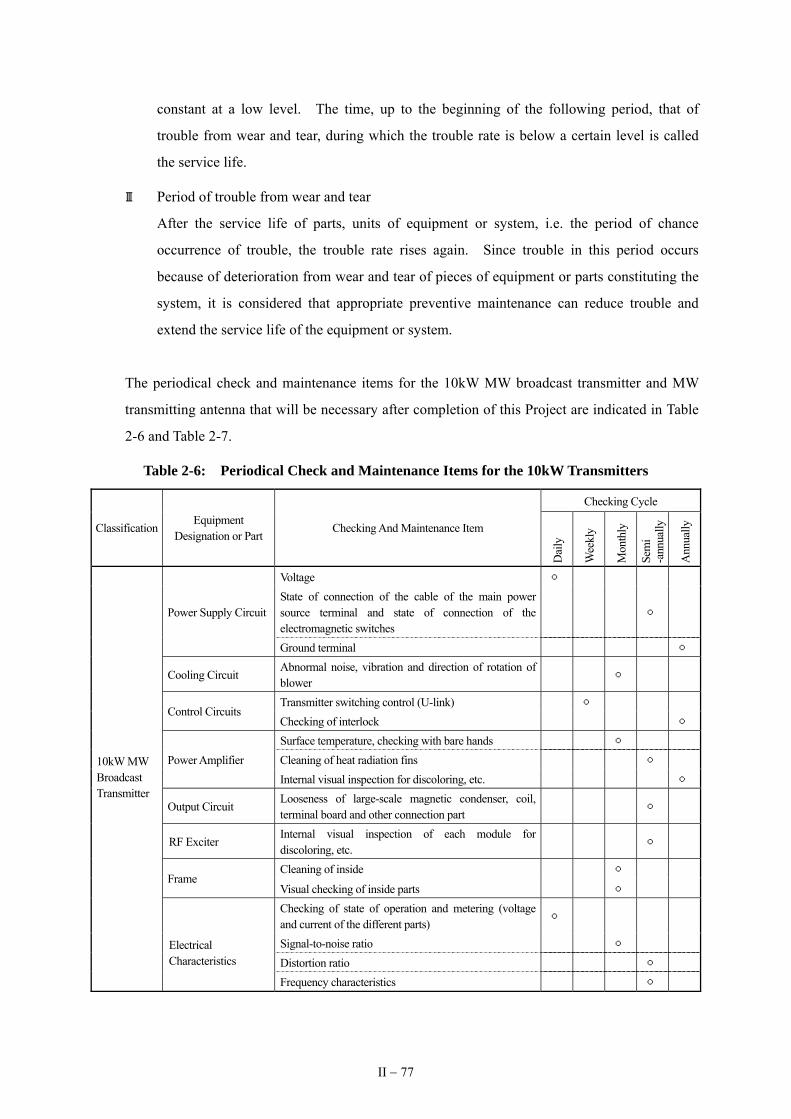
constant at a low level. The time, up to the beginning of the following period, that of
trouble from wear and tear, during which the trouble rate is below a certain level is called
the service life.
Ⅲ Period of trouble from wear and tear
After the service life of parts, units of equipment or system, i.e. the period of chance
occurrence of trouble, the trouble rate rises again. Since trouble in this period occurs
because of deterioration from wear and tear of pieces of equipment or parts constituting the
system, it is considered that appropriate preventive maintenance can reduce trouble and
extend the service life of the equipment or system.
The periodical check and maintenance items for the 10kW MW broadcast transmitter and MW
transmitting antenna that will be necessary after completion of this Project are indicated in Table
2-6 and Table 2-7.
Table 2-6: Periodical Check and Maintenance Items for the 10kW Transmitters
Checking Cycle
Classification Equipment
Designation or Part Checking And Maintenance Item
Dai
ly
Wee
kly
Mon
thly
Sem
i -a
nnua
lly
Ann
ually
Voltage
Power Supply Circuit State of connection of the cable of the main power source terminal and state of connection of the electromagnetic switches
Ground terminal
Cooling Circuit
Abnormal noise, vibration and direction of rotation of blower
Transmitter switching control (U-link)
Control Circuits Checking of interlock
Surface temperature, checking with bare hands Power Amplifier Cleaning of heat radiation fins Internal visual inspection for discoloring, etc.
10kW MW Broadcast Transmitter
Output Circuit Looseness of large-scale magnetic condenser, coil, terminal board and other connection part
RF Exciter
Internal visual inspection of each module for discoloring, etc.
Cleaning of inside
Frame
Visual checking of inside parts Checking of state of operation and metering (voltage
and current of the different parts)
Signal-to-noise ratio
Electrical Characteristics Distortion ratio
Frequency characteristics
II − 77

Table 2-7: MW Transmitting Antenna Periodical Check and Maintenance Items
Part Check and Maintenance Items Checking Cycle
Mast
Checking, by telescope, etc. from at least 2 directions, and repairing, if necessary, of verticality of the steel column from 2 directions perpendicular to one another, damage to bolts, rivets, the body of the tower, platform insulators, top hat, foundation, etc., displacement, state of fitting, etc.
7 to 8 years
Guys
Checking for, and repairing if necessary, deterioration, dirtiness, rusting corrosion, looseness, damage, etc. of the guy anchor blocks, wires, fittings (sockets, clips, turnbuckles, shackles, etc.), guy insulators, insulator fittings, guy choke coils, etc.
7 to 8 years
Accessory equipment
Checking for and repairing deterioration, dirtiness, rust corrosion, looseness, damage, etc. of air navigation obstruction lights, lightning rod, tuning house, tuning box, lead-in bowl-shaped insulators, power feed tubes, power feed lines, protective railing, etc.
7 to 8 years
Others The antenna masts will have to be periodically painted and repaired considering their location in coastal areas. 7 to 8 years
Furthermore, besides such checking and maintenance, it will be necessary to set up a budget for
planned procurement and renewal of the equipment for the sake of maintaining the functionality
of the broadcasting stations. The service lives of the main equipment to be procured in this
Project are set below on the basis of the actual experience to date of RRI and The Independent
State of Papua New Guinea (PNG), etc. of neighboring countries.
10kW MW broadcast transmitter : 15 years
Program input and monitoring equipment : 12 years
STL : 15 years
Air conditioner : 12 years
Emergency engine generator : 15 years
Digital audio mixer : 10 years
MW transmitting antenna : 50 years (It is necessary, however, to carry
out painting and checking and repair work
about every 7 to 8 years.)
(2) Facility Maintenance Management
Maintenance of the transmitting station buildings to be built by the Indonesian side will consist
mainly of routine cleaning and repairs and parts replacement for wear and tear, damage and
deterioration due to age of interior and exterior facings and finishes. For ongoing effective
maintenance it is desirable that RRI itself prepare a building maintenance manual that adequately
takes into account its operation and maintenance management system and the economic and
construction conditions in Indonesia.
II − 78

2-5 Outline of the Project Cost
2-5-1 The Project Cost
In case this Project is implemented under the grand aid scheme of the government of Japan, the
total project cost is estimated at 520 million Japanese Yen. Details of project cost to be born by
Japanese side and Indonesia side are estimated in accordance with the below conditions are as follows;
(1) The project cost to be born by Japanese side
Approximately 354 million
Items Cost (million Yen) Equipment for MW Radio Broadcasting System for Tolitoli Broadcasting Station 156
Equipment procurement & Installation Equipment for MW Radio Broadcasting
System for Tarakan Broadcasting Station 157.5 313.5
Consultant fee 40.5
This cost estimate is provisional and would be further examined by the Government of Japan for
the approval of the grant.
(2) The project cost to be born by the Indonesia side
Approximately 13.8 billion Rp (166 million Japanese Yen)
• Land preparation of the site for Tolitoli MW transmitting station
• Land preparation of the site for Tarakan MW transmitting station
• Construction of transmitter building, power supply building, STL tower, parking lot, etc. for
Toli-Toli MW transmitting Station
• Construction of transmitter building, power supply building, STL tower, parking lot, etc. for
Tarakan MW transmitting station
(3) Estimation conditions
1) Date of cost estimation: December, 2005
2) Exchange rate: 1US$ = 113.53 Japanese Yen
1Rp = 0.012 Japanese Yen
3) Implementation period: Refer to Implementation Schedule.
II − 79

2-5-2 Management Cost after Completion of the Project
(1) The Toli-Toli and Tarakan Broadcasting Stations
The necessary operation expense of RRI broadcasting stations consists of salary, program
production cost, the cost of electric power, water and communications, office expenses, travel
expenses for temporary assignment of personnel elsewhere, facility maintenance and repair
expenses, etc.
After implementation of the Project there will be neither increase in the number of personnel at
the Toli-Toli and Tarakan broadcasting stations nor increase in the quantity of program
production, which means that there will be no need for additional budget allocations for salary
and program production costs. Nor will there be installation of telephone service at the
transmitting stations, and the present budget allocations for office expenses can be shared
between the new transmitting stations and the existing broadcasting stations without requiring
any increase.
That being the case, about the only necessary new items of expense for operation and
maintenance of the Toli-Toli and Tarakan MW transmitting stations after implementation of the
Project will be ① electricity, ② water, ③ facility maintenance and repair and ④ miscellaneous.
The estimated additional annual operation and maintenance costs of the Toli-Toli broadcasting
station and the Tarakan broadcasting station after implementation of the Project are, respectively,
Rp 223,290,000 (about 2.7 million yen) and Rp 255,005,000 (about 3 million yen).
The budgets for running the two broadcasting stations have been allocated by RRI’s head office,
and the necessary additions to those budgets after project implementation will be coming from
there, too. RRI’s ordinary budget for 2005 was Rp 378,644,388,000 (about 4.54 billion yen),
and the total annual operation and maintenance costs of the two broadcasting stations after
implementation of the Project, estimated at Rp 478,345,000 (about 5.7 million yen), is only about
0.12% of that. Since the budgeting mechanism is one whereby the Government of Indonesia
increases the budget allocation to RRI for running its stations if RRI applies for such increase,
there will be no problem covering the necessary operation and maintenance costs after project
implementation. Details on those costs are given below:
Additional Annual Operation and Maintenance Cost After Project Implementation
Toli-Toli Broadcasting Station Tarakan Broadcasting Station Electricity Rp 120,176,000 Rp 152,678,000 Water Rp 3,114,000 Rp 2,327,000 Facility Maintenance and Repairs Rp 90,000,000 Rp 90,000,000
Other Costs Rp 10,000,000 Rp 10,000,000
Total Rp 223,290,000 Rp 255,005,000
II − 80

1) Electricity
① Annual electricity consumption
Item Capacity Power Factor
Operating Time
Hours of Operation a Year
Annual Consumption
Capacity
Annual Power Consumption
10kW MW Broadcast Transmitter 20kVA 0.95 18 h/day 6,570H 131,400kVA 124,830kW
Program Input and Monitoring Equipment 1kVA 0.95 18 h/day 6,570H 6,570kVA 6,241kW
STL 1kVA 0.95 18 h/day 6,570H 6,570kVA 6,241kW
Air Conditioner 5kVA 0.95 18 h/day 6,570H 32,850kVA 31,207kWObstruction Lighting System 1kVA 0.90 12 h/day 4,380H 4,380kVA 3,942kW
Fluorescent Lamps, etc. 1kVA 0.70 20 h/day 7,300H 7,300kVA 5,110kW
Total 177,571kW
② Table of electricity rates
Power Receiving Capacity Basic Rate Meter Rate
Toli-Toli 65kVA 30000Rp/kVA 545Rp/kWH
Tarakan 65kVA 25000Rp/kVA 750Rp/kWH
③ Annual charge for power consumption
Basic rate(65kVA×30,000Rp×12 months) Rp 23,400,000Toli-Toli MW Transmitting Station Meter rate(545Rp×177,571kWH) Rp 96,776,000
Total Rp 120,176,000
Basic rate(65kVA×25,000Rp×12 months) Rp 19,500,000Tarakan MW Transmitting Station Meter rate(750Rp×177,571kWH) Rp 133,178,000
Total Rp 152,678,000
2) Water
From the actual past experience of the existing broadcasting stations the monthly water
consumption is assumed to be 200m3.
① Water rates
Monthly basic rate (0 to 10m3) Meter rates
Toli-Toli 5,760Rp/month 1,043Rp/m3 (11 to 20 m3) 1,352Rp/m3 (over 21 m3)
Tarakan 35,000Rp/ month 5,250Rp/m3 (11 to 20 m3) 7,000Rp/m3 (21 to 30 m3)
10,500Rp/m3 (over 31 m3)
II − 81

② Annual charge for consumption of water
Basic rate (5,760 Rp/month × 12 months) Rp 69,000
Toli-Toli MW Transmitting Station
Meter rate(1,043Rp×10m3+1,352Rp ×180m3)×12 months) Rp 3,045,000
Total Rp 3,114,600
Basic rate(35,000 Rp/month × 12 months) Rp 420,000
Tarakan MW Transmitting Station
Meter rate(5,250Rp×10m3+7,000Rp×10m3
+10,500Rp×170 m3)×12 months Rp 1,907,000
Total Rp 2,327,000
3) Facility maintenance and repairs
This is the necessary cost of maintenance and repairs of the MW transmitting station
facilities. On the basis of the past experience of the broadcasting stations the annual cost
of that at each of the two transmitting stations is estimated at Rp 90,000,000. That does
not include the cost of procurement of spare parts, etc., for the transmitting equipment since
they will be supplied by the RRI head office.
4) Other expenses
For contingency costs an amount of Rp 10,000,000/year is assumed.
(2) RRI Head Office
Procurement of spare parts for maintenance of the broadcasting equipment is all being done by
the RRI head office. That being the case, the RRI head office needs to consider in its budget the
maintenance cost for trouble with the equipment to be procured in this project. In the past the
broadcasting stations estimated annual maintenance costs at about 1% of the cost of the
equipment, but now about 0.5% is considered enough in view of the lower frequency of trouble
brought about by technological progress.
On that basis it is estimated that the cost of maintenance of the MW broadcasting equipment to be
provided in this project will be about 85 million rupiah (about 1 million yen) a year, and thereof
that amount will have to be provided for in the budget.
II − 82

Chapter 3 Project Evaluation and Recommendations