BASIC DESIGN STUDY REPORT ON THE PROJECT FOR NAM …
65
BASIC DESIGN STUDY REPORT ON THE PROJECT FOR NAM NGUM I HYDROPOWER STATION REHABILITATION IN THE LAO PEOPLE’S DEMOCRATIC REPUBLIC JULY 2001 JAPAN INTERNATIONAL COOPERATION AGENCY NIPPON KOEI CO., LTD., TOKYO, JAPAN NO CR ( 1 ) G R 3 01-137
Transcript of BASIC DESIGN STUDY REPORT ON THE PROJECT FOR NAM …

BASIC DESIGN STUDY REPORT
ON
THE PROJECT
FOR
NAM NGUM I HYDROPOWER STATION REHABILITATION
IN
THE LAO PEOPLE’S DEMOCRATIC REPUBLIC
JULY 2001
JAPAN INTERNATIONAL COOPERATION AGENCY
NIPPON KOEI CO., LTD., TOKYO, JAPAN
NO
CR ( 1 )
G R 3
01-137

BASIC DESIGN STUDY REPORT
ON
THE PROJECT
FOR IMPROVEMENT OF EXISTING AIR TRAFFIC SERVICES
EQUIPMENT SYSTEM
UNDER THE TRIBHUVAN INTERNATIONAL AIRPORT
MODERNIZATION PROJECT
IN
THE KINGDOM OF NEPAL
JULY 1999
JAPAN INTERNATIONAL COOPERATION AGENCY
NIPPON KOEI CO., LTD., TOKYO, JAPAN


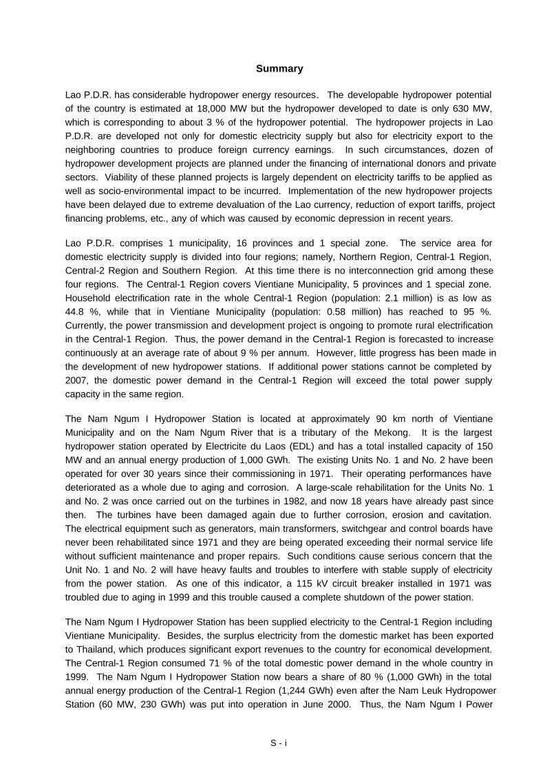
Nam Ngum I Hydropower Station
Turbine and Generator(Unit No. 1 and No. 2)

Nam Ngum I Hydropower Station
Generator Unit No. 1 and No. 2 from this side

LIST OF FIGURES AND TABLES
<FIGURES>
Figure 2-1 Reservoir Water Levels and Rated Net Heads of Turbine............................... 2 - 2
Figure 2-2 Nam Ngum I Hydropower Station Major Equipment for Rehabilitation ............ 2 - 16
<TABLES>
Table 1-1 Development of Nam Ngum I Hydropower Station ......................................... 1 - 1
Table 2-1 Net Heads, Discharge and Output .................................................................. 1 - 2
Table 2-2 Effect of Output Increase on Turbine Performance......................................... 2 - 4
Table 2-3 Additional Cost for Upgrading......................................................................... 2 - 6
Table 2-4 Normal Service Conditions and Climatic Conditions at Site ............................ 2 - 7
Table 2-5 List of Spare Parts to be Supplied.................................................................. 2 - 23
Table 2-6 List of Maintenance Tools to be Supplied ....................................................... 2 - 23
Table 2-7 List of Testing Instruments to be Supplied ...................................................... 2 - 24
Table 2-8 Grouping of Equipment in Two Contract Packages......................................... 2 - 28
Table 2-9 Implementation Schedule............................................................................... 2 - 37
Table 3-1 Effects by Implementation of This Project....................................................... 3 - 1

ABBREVIATIONS
ACSR : Aluminium Conductor Steel Reinforced
ADB : Asian Development Bank
BOT : Build-Operation-Transfer
EGAT : Electricity Generating Authority of Thailand
EDF : Electricite du France
EDL : Electricite du Laos
GDP : Gross Domestic Product
GWh : Gigawatt-hour
IBRD : International Bank for Reconstruction and Development
IDA : International Development Association
IEC : International Electrotechnical Commission
IPP : Independent Power Producer
JEC : Japanese Electromechanical Committee
JIS : Japanese Industrial Standard
LLDC : Least among Less-Developed Countries
MIH : Ministry of Industry and Handicraft
MVA : Megavolt-ampare
MW : Megawatt
NDF : Nordic Development Fund
OJT : On-the-job Training
OPEC : Organization of Petroleum Exporting Countries
S - i
Summary
Lao P.D.R. has considerable hydropower energy resources. The developable hydropower potentialof the country is estimated at 18,000 MW but the hydropower developed to date is only 630 MW,which is corresponding to about 3 % of the hydropower potential. The hydropower projects in LaoP.D.R. are developed not only for domestic electricity supply but also for electricity export to theneighboring countries to produce foreign currency earnings. In such circumstances, dozen ofhydropower development projects are planned under the financing of international donors and privatesectors. Viability of these planned projects is largely dependent on electricity tariffs to be applied aswell as socio-environmental impact to be incurred. Implementation of the new hydropower projectshave been delayed due to extreme devaluation of the Lao currency, reduction of export tariffs, projectfinancing problems, etc., any of which was caused by economic depression in recent years.
Lao P.D.R. comprises 1 municipality, 16 provinces and 1 special zone. The service area fordomestic electricity supply is divided into four regions; namely, Northern Region, Central-1 Region,Central-2 Region and Southern Region. At this time there is no interconnection grid among thesefour regions. The Central-1 Region covers Vientiane Municipality, 5 provinces and 1 special zone.Household electrification rate in the whole Central-1 Region (population: 2.1 million) is as low as44.8 %, while that in Vientiane Municipality (population: 0.58 million) has reached to 95 %.Currently, the power transmission and development project is ongoing to promote rural electrificationin the Central-1 Region. Thus, the power demand in the Central-1 Region is forecasted to increasecontinuously at an average rate of about 9 % per annum. However, little progress has been made inthe development of new hydropower stations. If additional power stations cannot be completed by2007, the domestic power demand in the Central-1 Region will exceed the total power supplycapacity in the same region.
The Nam Ngum I Hydropower Station is located at approximately 90 km north of VientianeMunicipality and on the Nam Ngum River that is a tributary of the Mekong. It is the largesthydropower station operated by Electricite du Laos (EDL) and has a total installed capacity of 150MW and an annual energy production of 1,000 GWh. The existing Units No. 1 and No. 2 have beenoperated for over 30 years since their commissioning in 1971. Their operating performances havedeteriorated as a whole due to aging and corrosion. A large-scale rehabilitation for the Units No. 1and No. 2 was once carried out on the turbines in 1982, and now 18 years have already past sincethen. The turbines have been damaged again due to further corrosion, erosion and cavitation.The electrical equipment such as generators, main transformers, switchgear and control boards havenever been rehabilitated since 1971 and they are being operated exceeding their normal service lifewithout sufficient maintenance and proper repairs. Such conditions cause serious concern that theUnit No. 1 and No. 2 will have heavy faults and troubles to interfere with stable supply of electricityfrom the power station. As one of this indicator, a 115 kV circuit breaker installed in 1971 wastroubled due to aging in 1999 and this trouble caused a complete shutdown of the power station.
The Nam Ngum I Hydropower Station has been supplied electricity to the Central-1 Region includingVientiane Municipality. Besides, the surplus electricity from the domestic market has been exportedto Thailand, which produces significant export revenues to the country for economical development.The Central-1 Region consumed 71 % of the total domestic power demand in the whole country in1999. The Nam Ngum I Hydropower Station now bears a share of 80 % (1,000 GWh) in the totalannual energy production of the Central-1 Region (1,244 GWh) even after the Nam Leuk HydropowerStation (60 MW, 230 GWh) was put into operation in June 2000. Thus, the Nam Ngum I Power

S - ii
Station is the most important power station for EDL even now.
In Lao P.D.R., the domestic power demand will positively increase year by year and no alternativeenergy is available at present. Therefore, the rehabilitation of the Nam Ngum I Hydropower Stationis urgently required to realize a stable supply of electricity.
Under such circumstances, the Government of Lao P.D.R. requested a Grant Aid to the Governmentof Japan for the rehabilitation of the Units No. 1 and No. 2 at the Nam Ngum I Hydropower Station.
In response to the request from the Government of Lao P.D.R., the Government of Japan decided toconduct a basic design study on the Project for the Nam Ngum I Hydropower Station Rehabilitationand entrusted the study to the Japan International Cooperation Agency (JICA). JICA sent to LaoP.D.R. a study team from January 22 to February 25, 2001. The study team held discussions withthe officials concerned of the Government of Lao P.D.R., and conducted a field survey at the projectsite. This study aimed not only to formulate the contents and scope of work for the Project but alsoto ascertain the effect of the project and the eligibility for the Japan’s Grant Aid program. After theteam returned to Japan, further studies were made. Then, a mission was sent to Lao P.D.R. inorder to discuss a draft basic design.
This Japan’s Grant Aid program is to provide non-reimbursable funds to procure the goods andservices required for implementation of the Project for the rehabilitation of the Nam Ngum IHydropower Station, which aims to restore the existing Unit No. 1, Unit No. 2 and their associatedcommon equipment to their original conditions. The basic policy for the rehabilitation plan is asfollows:
(1) Rehabilitation is to achieve further long-term operation of the Units No. 1 and No. 2.
(2) Primary objective of rehabilitation is to restore the existing equipment to its original constructionand/or performance. In case necessary replacement parts and spare parts are no longeravailable in the market and/or the restoration to the original condition has no economic merit, theequipment should be renewed with current technology.
(3) In principle, rehabilitation will be applied to the existing equipment of which the rehabilitation ishighly essential and urgently required for keeping it in service consecutively.
(4) The scope of rehabilitation on the control and relay boards will be limited to the requiredminimum. This is because the control and relaying systems for the Units No. 1 and No. 2 willpreferably be modernized together with the Units Nos. 3 to 5 in the near future.
(5) The turbine parts using grease lubricant, which is causing water pollution, will be renewed withgrease-less construction and the electrical equipment containing toxic chemicals will berenewed with harmless design, to minimize adverse effect to the surrounding environment.
(6) The turbine discharge will be recovered to the original design value. The turbine discharge hasbeen currently decreased due to the elevated reservoir water level after completion of the UnitsNo. 1 and No. 2. (As a result, the output of Units No. 1 and No. 2 will increase by 2.5 MW x 2)

S - iii
Following the examination into the request from Lao P.D.R., the rehabilitation plan is formulated asfollows:
Equipment Extent of Rehabilitation
1. Turbines Repair
2. Generators Repair(Excitation Equipment: Renewal)
3. Intake Gates and Control Panels Repair(Control Panels: Renewal)
4. Protective Relays Supply of Spare Overcurrent Relay
5. Governors and Pressure Oil Supply System Repair(Governors: Renewal)
6. Air Compressors Repair
7. Water Supply System and Drainage System Repair(Drainage Pump: Renewal)
8. Overhead Traveling Crane Repair
9. Main Transformers Renewal(Fire Extinguishing System: Repair)
10. 11 kV Switchgear Renewal
11. 110 V DC Supply Equipment Renewal
12. 115 kV Switchyard Equipment and Busbars Repair (Partly Renewal)
13. House-Service Transformer 22/0.38 kV Transformer: Renewal
14. Control Boards Repair
15. Gantry Cranes Operator Consoles: Renewal
This Project will be completed in 25 months calculated from the conclusion of the Exchange of Notes(E/N) by both Governments. This schedule includes 4 months for bidding and conclusion of thecontract(s), and 21 months for manufacturing, transportation, site rehabilitation works, site tests andtransfer of technology.
The execution of this Project will have the following beneficial effects:
1) The technical performance, reliability and safety of the Units No. 1 and No. 2 will be restoredand the extension of service life can be expected by implementation of the Project.
2) The rated output of the Unit No. 1 and No. 2 will increase from 15 MW x 2 to 17.5 MW x 2 andthe total installed capacity of the Nam Ngum I Hydropower Station will increase from 150 MW to155 MW. This additional output will make some contribution to enhance revenues to thecountry from the power generation.
3) The Units No. 1 and No. 2 can be operated with high working ratio as they used to do before.This will come to restore and improve the reliability of power supply of the entire power station.Then, the Nam Ngum I Hydropower Station is able to continue its important role in a stablesupply of electricity to domestic market as well as acquisition of export revenue by electricityexport to Thailand.
4) The frequency of maintenance intervention and the possibility of faults and troubles on the UnitsNo.1 and No. 2 will be reduced so that the maintenance cost will be greatly mitigated.

S - iv
5) The technical skills for dismantling and re-assembling of the turbines and generators will betransferred to the EDL’s maintenance crews through on-the-job-training so that periodicaloverhaul and trouble shooting in case of emergency of the turbines and generators can bemanaged by them. Especially, this Project will provide a greater opportunity for youngengineers to learn the power station equipment.
Thus, innumerable benefits are expected by the implementation of the Project. In this respect, thisProject has a great significance in being implemented under the Japan’s Grant Aid program.

- i -
CONTENTS
Preface
Letter of Transmittal
Location Map/Perspective
List of Figures and Tables
Abbreviations
Summary
CHAPTER 1 BACKGROUND OF THE PROJECT
CHAPTER 2 CONTENTS OF THE PROJECT
2.1 Basic Concept of the Project ...................................................................................... 2 - 1
2.2 Basic Design of the Requested Japanese Assistance................................................... 2 - 1
2.2.1 Design Policy ............................................................................................ 2 - 1
2.2.1.1 Basic Design Policy..................................................................... 2 - 1
2.2.1.2 Examination on Restoration of Turbine Discharge............................ 2 - 2
2.2.1.3 Design Policy for Environmental Conditions .................................... 2 - 6
2.2.1.4 Policy for Applied Standards ......................................................... 2 - 7
2.2.1.5 Policy for Utilization of Local Contractor and Local Materials............ 2 - 7
2.2.1.6 Policy for Transfer of Technology for Operation and Maintenance...... 2 - 7
2.2.1.7 Policy for Scope and Grade of Works ............................................ 2 - 8
2.2.1.8 Policy for Construction Time Schedule........................................... 2 - 9
2.2.2 Basic Plan................................................................................................. 2 - 10
2.2.3 Basic Design Drawing................................................................................. 2 - 25
2.2.4 Implementation Plan................................................................................... 2 - 26
2.2.4.1 Procurement Plan........................................................................ 2 - 26
2.2.4.2 Implementation Policy .................................................................. 2 - 29
2.2.4.3 Implementation Conditions............................................................ 2 - 32
2.2.4.5 Scope of Works........................................................................... 2 - 33
2.2.4.6 Consultant Supervision................................................................. 2 - 33
2.2.4.7 Quality Control Plan..................................................................... 2 - 36
2.2.4.8 Implementation Schedule.............................................................. 2 - 36
2.3 Obligations of Recipient Country ................................................................................. 2 - 38
2.3.1 Works to be Executed by Lao Side.............................................................. 2 - 38
2.3.2 Project Cost Estimation.............................................................................. 2 - 41
2.4 Project Operation Plan............................................................................................... 2 - 42

- ii -
CHAPTER 3 PROJECT EVALUATION AND RECOMMENDATION
3.1 Project Effect ............................................................................................................ 3 - 1
3.2 Recommendations..................................................................................................... 3 - 2
[DRAWINGS]
[APPENDICES]
1. Member List of the Study Team
2. Study Schedule
3. List of Parties Concerned in the Recipient Country
4. Minutes of Discussions
5. Cost Estimate Borne by the Recipient Country
6. References

CHAPTER 1
BACKGROUND OF THE PROJECT

1 - 1
CHAPTER 1 BACKGROUND OF THE PROJECT
The Nam Ngum I Hydropower Station is located at approximately 90 km north of VientianeMunicipality and on the Nam Ngum river that is a tributary of the Mekong. It is the largesthydropower station operated by Electricite du Laos (EDL) and has a total installed capacity of 150MW and an annual energy production of 1,000 GWh.
The Nam Ngum I Hydropower Station was constructed in three stages as shown in Table-1.
Table 1-1 Development of Nam Ngum I Hydropower Station
Installation of Units Output Completion
First Stage Units No. 1 and No. 2 15 MW x 2 1971
Second Stage Units No. 3 and No. 4 40 MW x 2 1978
Third Stage Unit No. 5 40 MW x 1 1984
The existing Units No. 1 and No. 2 have been operated for over 30 years since its commissioning in1971. Their operating conditions have deteriorated as a whole due to aging and corrosion. Alarge-scale rehabilitation for the Units No. 1 and No. 2 was once carried out on the turbines in 1982,and now 18 years have already past since then. The turbines have been damaged again due tofurther corrosion, erosion and cavitation. The electrical equipment such as generators, maintransformers, switchgear and control boards have never been rehabilitated since 1971 and they areoperated exceeding their normal plant life without sufficient maintenance and proper repairs.Therefore such electrical equipment causes serious concern over the possibility of heavy faults andtroubles. Actually, a 115 kV circuit breaker installed in 1971 was troubled due to aging in 1999 andthis trouble caused a complete shutdown of the power station.
The Nam Ngum I Hydropower Station has been supplied electricity to the Central-1 Region includingVientiane Municipality. Besides, the surplus electricity from the domestic market has been exportedto Thailand, which produces significant export revenues to the country for economical development.
The Central-1 Region consumed 71 % of the total domestic power demand in the whole country in1999. The Nam Ngum I Hydropower Station now bears a share of 80 % (1,000 GWh) in the totalannual energy production of the Central-1 Region (1,244 GWh) even after the Nam Leuk HydropowerStation (60 MW, 230 GWh) was added in June 2000. Thus, the Nam Ngum I Power Station is themost important power station for EDL. In Lao P.D.R., the domestic power demand will positivelyincrease year by year and no alternative energy is available at present. Therefore, the rehabilitationof the Nam Ngum I Hydropower Station is urgently required to realize a stable supply of electricity.
Under such circumstances, the Government of Lao P.D.R. requested a grant aid to the Governmentof Japan for the rehabilitation of the Units No. 1 and No. 2 at the Nam Ngum I Hydropower Station.

CHAPTER 2
CONTENTS OF THE PROJECT

2 - 1
CHAPTER 2 CONTENTS OF THE PROJECT
2.1 Basic Concept of the Project
The Nam Ngum I Hydropower Station is the largest hydropower station operated byElectricite du Laos (EDL) and has a total installed capacity of 150 MW and an annual energyproduction of 1,000 GWh. It was commissioned in 1971 and has performed well for 30years for supplying electricity to the Central-1 Region including Vientiane Municipality.Besides, the surplus electricity from the domestic market has been exported to Thailand toprovide export revenue to the country for economic development.
The existing Units No. 1 and No. 2 have been operated for over 30 years since itscommissioning in 1971. Their operating conditions have deteriorated as a whole due toaging and corrosion. Such conditions causes serious concern that the Units No. 1 and No.2 will have heavy faults and troubles to interfere with stable supply of electricity from thepower station.
Currently, the power transmission and development project is ongoing to promote ruralelectrification in the Central-1 Region. Thus, the power demand in the Central-1 Region isforecasted to increase continuously at an average rate of about 9 % per annum. However,little progress has been made in the development of new hydropower stations.
Under such circumstances, the Government of Lao P.D.R. has an intention of restoring thereliability of the Nam Ngum I Hydropower Station in order to keep its important role not onlyfor a stable supply of electricity to domestic market but also for electricity export to Thailand.
The objective of this Project is to rehabilitate the Unit No. 1, Unit No. 2 and the associatedstation common equipment, which is essential to their operation, for restoration of theirtechnical performances, reliability and safety to the original conditions to achieve their furtherlong-term operation.
Necessary goods and services for implementation of the Project will be procured andinstalled under the Japan’s grant aid program.
2.2 Basic Design of the Requested Japanese Assistance
2.2.1 Design Policy
2.2.1.1 Basic Design Policy
The rehabilitation plan was formulated based on the following design policies.
(1) The rehabilitation is to achieve further long-term operation of the Units No. 1 and No. 2.
The service life of the generating equipment for hydropower plants is expected to be 50to 60 years. A large-scale rehabilitation on the Units No. 1 and No. 2 will extend theirservice life for 20 to 30 years more until complete renewal of their whole units becomenecessary.
This Project is aiming to achieve successful continuous operation of the Units No. 1 forat least 20 years more.

2 - 2
(2) Primary objective of rehabilitation is to restore the existing equipment to its originalperformances and/or conditions. In case necessary replacement parts and spare partsare no longer available in the market and/or the restoration to the original condition hasno economic merit, the equipment should be renewed with current technology.
(3) In principle, rehabilitation will be applied to the existing equipment of which therehabilitation is highly essential and urgently required for keeping it in serviceconsecutively.
(4) The scope of rehabilitation on the control and relay boards will be limited to the requiredminimum. This is because the control and relaying systems for the Units No. 1 and No.2 will preferably be modernized together with the Units Nos. 3 to 5 in the near future.
(5) The turbine parts using grease lubricant, which is causing water pollution, will berenewed with grease-less construction and the electrical equipment containing toxicchemicals will be renewed with harmless design, to minimize adverse effect to thesurrounding environment.
(6) The turbine discharge will be recovered to the original design value. The turbinedischarge has been currently decreased due to the elevated reservoir water level aftercompletion of the Units No. 1 and No. 2. (As a result, the output of Units No. 1 and No.2 will increase by 2.5 MW x 2 to 17.5 MW x 2.)
2.2.1.2 Examination on Restoration of Turbine Discharge
(1) Background of This Examination
At the second stage development for the Units No. 3 and No. 4, the spillway gates wereadded on the dam. Consequently, the maximum and average water levels of thereservoir became 10 m and 5 m higher respectively than they were when the Units No. 1and No. 2 were installed. The rated net head for the turbines No. 1 and No. 2 wasdesigned at 32 m, while that for the turbines Nos. 3 to 5 was set at 37 m to suit theelevated water level of the reservoir.
Figure 2-1 Reservoir Water Levels and Rated Net Heads of Turbines
Rated WL of Tailrace: EL. 165.5 m
Max. WL. at completion of Units 1 & 2: EL. 202.5 m
Max. WL after completion of Units 3 & 4:212.5 m
Min. Operational Level: EL. 196.0 m
Rated WL for Units 1 & 2: EL. 200.0 m
Rated WL for Units 3 & 4 : EL. 205.0 m
Rated Head for Units 1 & 2:32.0 m
Rated Head for Units 3 & 4:37.0 m
Dam

2 - 3
The Units No. 1 and No. 2 cannot operate with loads exceeding their rated output.Whenever operating at net heads higher than their rated net head of 32 m, the turbine isforced to limit its discharge to smaller than the rated so that the turbine output should notexceed its rated one. The maximum discharge of the Units No. 1 and No. 2 at a nethead of 37 m is estimated at 83 % of the rated.
On the other hand, the inflow to the Nam Ngum I Reservoir has increased by additionalinflow from the Nam Son Diversion and the Nam Leuk Hydropower Station. This willcause a spill-out of the water from the dam. Actually, a lot of spill-outs were observedin 2000.
It is a basic design policy to change the rated net head of the turbines No. 1 and No. 2from 32 m to 37 m, which is equal to that for the turbines Nos. 3 to 5, and to recover theturbine discharge to the rated value originally designed for them.
The recovery of the turbine discharge will cause changes of the equipment ratings.The capabilities of the rehabilitated turbines and generators as well as necessarychange of the equipment specifications were examined in the following articles.
The following examinations concluded that the turbine discharge can be recoveredwithout any technical problem and the recovery of the turbine discharge will come toupgrade the Units No. 1 and No. 2 to 17.5 MW x 2. In addition, the examinations showthat the upgrading of the Units No. 1 and No. 2 is technically and economicallyreasonable.
(2) Turbines
The existing turbines No. 1 and No. 2 was designed to operate safely and satisfactory atany net heads between 32 m to 45.5 m and at any discharges up to the rated dischargeof 55.4 m3/s. The turbines are therefore able to operate at a net head of 37 m and adischarge of 55.4 m3/s without any technical problem.
The turbine output is determined by a net head and a turbine discharge. If net headand turbine discharge are changed, the turbine output is also changed.
Table 2-1 Net Head, Discharge and Output
Net Head Discharge TurbineOutput
GeneratorOutput
Original Design 32 m 55.4 m3/s 15.5 MW 15.0 MW
Present Operating Condition 37 m 46.0 m3/s 15.5 MW 15.0 MW
Basic Plan 37 m 55.4 m3/s 18.3 MW 17.5 MW
If the turbine discharge is recovered to 55.4 m3/s at the rated net head of 37 m, theturbine rated output will increase to 18.3 MW.
On the other hand, an increase of turbine output will modify the turbine performance.Whether the turbine output can be increased or not is technically dependent on themodified turbine performance. The technical examination was therefore required for

2 - 4
the following performances.
(a) Maximum pressure
Maximum pressure means maximum momentary pressure developed in the turbineand penstock during a sudden load rejection of the generator. The maximumpressure should not exceed 65.4 m, which is the guaranteed value for the exitingturbines No. 1 and No. 2.
(b) Maximum speed rise
Maximum speed rise means maximum momentary speed rise caused by suddenfull load rejection of the generator. According to current practice in Japan,maximum speed rise for Francis turbine is generally set at 45 to 50 %.
(c) Suction head
Static suction head is conveniently defined as a level difference between elevationof the turbine (guide vane) centerline and the tailrace water level. Insufficientsuction head will cause cavitation problem on the turbine. When the rated outputof the turbine is changed, a change of the suction head will be required in thecalculation. However, the actual suction head is unchanged because the turbinecenter elevation cannot be changed. Therefore, it will be required to ascertain thata suction head calculated for the new turbine output has a sufficient safety marginon the actual suction head.
The results of the technical examination on the above three items are summarized inTable 2-2.
Table 2-2 Effect of Output Increase on Turbine Performance
TurbineOutput
MaximumPressure
MaximumSpeed Rise
Margin onSuction Head
Original Design 15.5 MW 65.4 m 37 % + 1.12 mBasic Plan 18.3 MW 65.4 m 44 % + 1.93 mCriteria - 65.4 m or less 50 % or less + 1.12 m or moreJudgement - No Problem No Problem No Problem
As shown in Table 2-2, upgrading of the turbine output will have no problem with theturbine performance. Accordingly, upgrading of the turbine output is technicallyfeasible.
(3) Generators
The replacement of the generator stator windings is planned but the existing stator coresand rotors are to be re-used for the rehabilitated generators. Although the turbineoutput can be increased, upgrading of the Units No. 1 and No. 2 will not be achievedunless the generator output can be increased by the rehabilitation of the generator.The examination was carried out to check whether the generator output is possible to be

2 - 5
increased only by the replacement of the stator windings.
The stator winding will be replaced in the manufacturer’s current standard practice usingthe latest materials. The replacement of the stator winding will come in effect toincrease the current carrying capacity of the winding, to reduce losses in the windingand to improve the generator efficiency a little bit. That is why the generator output canbe increased by the replacement of the stator windings. This increase can be achievedas a natural consequence because the replacement windings need to fit into the existingstator slots to be re-used. Therefore, no additional cost is required for the increase ofthe generator output.
According to the technical analysis on the temperature rise of the generator windings,the rehabilitated generator can be upgraded to not less than 20 MVA on continuous dutyalthough the existing rotor is re-used.
In this connection, the output of the rehabilitated generator can be limited theoretically tothe existing one (17.5 MVA) if smaller size of conductor is applied to the new statorwindings. In this case, additional spacers of a little bit thick are required to fill the gapsbetween stator coil and stator slot and between stator coil and stator wedge to hold thestator coil securely. Such additional spacers are liable to be loosening subject to slightelectro-magnetic oscillation and will shorten the life of the stator windings.
This idea will be costly for the following reasons.
i) Manufacturing design for the additional spaces are required.ii) Space insert works are additionally required and the period for the
replacement works will become longer.iii) The cost for site supervisor will increase for the additional spacer work.
Therefore, such design to forcedly limit the generator output is not practicable from bothtechnical and economical points of view. The continuous output of the rehabilitatedgenerator can be increased to 20 MVA as a natural consequence of the replacement ofthe stator windings.
In conclusion, the replacement of the stator windings by using a current standardpractice is technically and economically reasonable. Therefore, it is planned to changethe turbine rated output to 18.3 MW and the generator rated output to 17.5 MW (20MVA).
(4) Rating of Other Equipment
According to the basic plan of this Project, the existing excitation equipment and maintransformers are to be renewed because of serious deterioration due to aging. On therenewal of these items, their capacities need to be increased to successfully achieve theupgrading of the Units No. 1 and No. 2.
By the way, the normal current on the generator and main transformer circuits will beincreased by 14.3 % in proportion to the upgrading of the generators and maintransformers. However, the power cables, switchgear and instrument transformers on

2 - 6
the associated circuits have sufficient current ratings and no change is required on theirspecifications.
(5) Cost and Effect of Upgrading of Units No. 1 and No. 2
Additional cost is required to increase the capacities of the excitation equipment andmain transformers. The desired effect for the additional cost was examined as follows:
(a) Additional cost for upgrading
Additional cost to increase the output of the two units from (15 MW x 2) to (17.5MW x 2) is estimated as follows:
Table 2-3 Additional Cost for Upgrading
No Upgrading Upgrading Additional CostTurbine Output 15.5 MW x 2 18.3 MW x 2 ¥ 0Generator Output 17.5 MVA x 2 20.0 MVA x 2 ¥ 0Excitation Capacity 260 kVA x 2 280 kVA x 2 ¥ 700,000Transformer Power 17.5 MVA x 2 20.0 MVA x 2 ¥ 7,000,000Total ¥ 7,700,000
(b) Construction cost for alternative power plant
The restoration of the turbine discharges will result in upgrading the total output ofthe Units No. 1 and No. 2 by 5 MW (2.5 MW x 2).
A diesel power plant is usually considered as an alternative power plant with theinstalled capacity of 5 MW. If the construction cost is assumed at US$ 1,500/kW,the construction of the 5 MW diesel power plant will cost ¥ 898,425,000.
(c) Additional revenue by upgrading of the output
If the increase of the output (5 MW in total) is all exported to Thailand, theadditional revenue is estimated at ¥ 98,000,000 per annum. This estimate isbased on the assumption that export tariff is 0.03 US$/kWh, load factor is 70 % forboth the Units No. 1 and No. 2 and transmission efficiency is 89 %.
It is ascertained by these examinations that the upgrading of the Units No. 1 and No. 2is technically and economically reasonable.
2.2.1.3 Design Policy for Environmental Conditions
Since the project site is located in tropical climate, ambient air and water temperatures arerelatively high. At the project site, yearly average ambient temperature is 7.4 °C higher thanthe normal service condition for designing the equipment, and average water temperature is5 °C higher than it as shown in Table 2-4.
Yearly average ambient temperature will affect the temperature limit on the transformers andwater temperature will affect the cooling effect of the water-cooled equipment. The renewal

2 - 7
of these items needs to be designed considering such high temperature conditions.
Table 2-4 Normal Service Conditions and Climatic Conditions at Site
Normal Service Conditions Climatic Conditions at Site
Altitude Not exceeding 1,000 m 160 m to 230 m
Max. ambient temperature Not exceeding 40 °C 34.7 °C
Yearly average ambienttemperature
Not exceeding 20 °C 27.4 °C
Water temperature Not exceeding 25 °C 30.0 °C (18.8 °C - 32.8 °C)
2.2.1.4 Policy for Applied Standards
The Japanese Industrial Standard (JIS) and the Japanese Electrotechnical CommitteeStandard (JEC) will generally be applied to the design, materials, manufacture, testing,inspection and performance of all electrical and electromechanical equipment. TheInternational Electrotechnical Commission Standard (IEC) will also be acceptable.
Particularly, the IEC standard will be applied to the main transformers that will be procuredfrom Japan or from the third country.
2.2.1.5 Policy for Utilization of Local Contractor and Local Materials
Most of local contractors for electrical works are mainly working for the construction ofsubstations, distribution lines and transmission lines. However, they have no experience forinstallation of generating equipment except mini hydropower stations. Since localcontractors have no sufficient number of skilled and qualified workers, the utilization ofcontractors in Thailand or other third countries needs to be considered for this Project.
A marketing survey shows that the equipment and materials available in Lao P.D.R. for theProject will be limited to some consumables and materials for temporary facilities, such aslubricating oil, grease, paint, etc.
2.2.1.6 Policy for Transfer of Technology for Operation and Maintenance
Proper operation and maintenance of the rehabilitated equipment is essentially required tosecure the desired effect of the rehabilitation for long time. Technical knowledge and skillswill be transferred to the EDL’s personnel to ensure that the equipment rehabilitated underthis Project can be operated and maintained properly by them.
(1) Guidance and Instructions for Operation and Maintenance of Renewed Equipment
The system configurations of the governors and the excitation equipment will bechanged entirely by renewal of these items. Accordingly, their operation andmaintenance methods will also be changed.
Operation guidance and maintenance instructions for these items will be provided at thesite by the contractor to the operators and maintenance crews before the first

2 - 8
rehabilitated unit is put into operation. Necessary instruction manuals for operation andmaintenance of the associated equipment will be prepared by the contractor.
(2) Technical Guidance for Recording of Operation Data and Maintenance Events
Operation data and maintenance results should be recorded properly and compiled as adatabase for the operation management and scheduling of the future maintenance plans.
The technical guidance for improvements in data recording will be provided at the site bythe Consultant to the operators and maintenance crews before the first rehabilitated unitis put into operation.
(3) Transfer of Technical Skills for Dismantling and Reassembling of Turbines andGenerators
Technical skills for dismantling and reassembling of the turbines and generators areessentially required in order that periodical overhaul and trouble shooting in case ofemergency of the turbines and generators can be managed by EDL own.
Transfer of the technical skills will be done by the contractor through on-the-job-training.For this purpose, at least ten (10) personnel of the maintenance crews will participatedirectly in the site rehabilitation works of the turbines and the generators. Workingprocedures and manuals for the disassembling and reassembling works will be preparedby the contractor.
2.2.1.7 Policy for Scope and Grade of Works
(1) Design Policy for Further Long-Term Operation of Units No. 1 and No. 2
The contents of the rehabilitation will be necessary and sufficient to achieve successfulcontinuous operation of the Units No. 1 for at least 20 years more.
The equipment and parts to be re-used will be overhauled as far as possible during thesite rehabilitation work, to maintain their present performance and functions.
(2) Attention to Existing Civil and Building Structures
The renewed equipment will be installed at the same place as the existing one by usingthe existing foundations and floor openings as much as possible to minimize themodification of the existing civil and building structures.
Especially, the main transformers and other heavy equipment will be fixed exactly at thesame locations as the existing ones in order not to change the loading conditions on theexisting structures.
(3) Attention to Other Units and Remaining Parts Not Covered by the Project
The rehabilitation works will be programmed so as not to interfere with continuousoperation of the other units and will be carried out with careful attention to the existingequipment and remaining parts that are not covered by this Project. Necessary

2 - 9
coordination and interface with the existing equipment/parts to be re-used and the civiland building structures will be incorporated in designing the rehabilitation works.
2.2.1.8 Policy for Construction Time Schedule
The rehabilitation works for the Units No. 1 and No. 2 will be carried out for each unit oneafter another taking into account the working space, manpower and manufacturing schedule.Five (5) months of the unit shutdown will be required for the rehabilitation works for each unitincluding site tests and transfer of technology to the EDL’s personnel.
The implementation schedule for each unit will be 16 months including design, procurement,manufacturing, transportation, site rehabilitation works, site tests and transfer of technology.If the site rehabilitation works for the two units will be done in series, the overallimplementation schedule will take twenty-one (21) months.
Judging from the required time schedule, the Project will be implemented from 2002 to 2004.

2 - 10
2.2.2 Basic Plan
(1) Overall Plan
Following the examination into the request from Lao P.D.R. based on the results of thefield survey and the Design Policy described in Clause 2.2, the rehabilitation plan isformulated as tabulated below. The principal equipment for the rehabilitation is shownin Figure 2-2.
Equipment Results of Site Survey Contents of Rehabilitation
1. Turbines Repair of two (2) turbinesTurbine Interior • Damaged by corrosion, erosion
and cavitationRepair with overlay, surfacepreparation and coating
• Corrosion on metallic parts Surface preparation and coatingTurbine operatingmechanism • Grease leakage from bearings Change to grease-less bearings
Shaft sealing box • Grease leakage from seals Change to grease-less seals
• Deterioration of bearing metals Replace of bearing metals
• Deterioration of lubricating oil Replace of lubricating oil
• Corrosion on bearing housing Replace of housing and coolingcoils
• Failure of some detectors Replace of defective detectors
Guide bearing
• Deterioration of resistancetemperature detectors (RTD)
Replace of RTD
• Deterioration of pressure gauges Replace of pressure gaugesInstrumentation
• Failure of pressure switches Replace of pressure switches
Others • Not overhauled for 20 years Overhaul of each turbine part
2. Governors • Old and obsolescent type• Spare parts are not available
because of obsolescence• Deterioration as a whole• Failure of distribution valves
• Frequent trouble with speeder• Failure of limit switches
Renewal of governors
Change to electro-hydraulic typeof latest design
• Deterioration of pressure oil Replace of pressure oil
• Paint peeling from pressure tank Cleaning and coating
• Paint peeling from sump tank Cleaning and coating
• Oil leakage from valves Replace of valves
• Deterioration of pressure gaugesand oil level gauges
Replace of pressure gauges andoil level gauges
3. Pressure Oil System
• Failure of pressure switches Replace of pressure switches
• Failure of safety valves andautomatic drain valves
Replace of safety valves andautomatic drain valves
• Deterioration of pressure gauges Replace of pressure gauges
4. Compressed Air System
• Failure of pressure switches Replacement of the switches

2 - 11
Equipment Results of Site Survey Contents of Rehabilitation
• Corrosion on pipes Replace of exposed pipes
• Failure of strainer Replace of strainer5. Cooling Water System
• Corrosion and failure of valves Replace of valves
• Corrosion on pipes Replace of exposed pipes
• Corrosion and failure of valves Replace of valves
6. Drainage System
• Failure of a drainage pump Replace of the drainage pump
7. Generators Repair of two (2) generators• Residual insulation withstand-
ability of the windings isestimated at 65 %.
• Deterioration of insulationmaterials of the windings
• Removal and loosening ofwedges
Replace of stator windingsStator windings
• Deterioration of resistancetemperature detectors (RTD)
Replace of RTD
• Not overhauled for 20 years Deformation checkRe-tightening of core bolts
Stator cores
• Contamination and rust Cleaning, removal of rust andvarnishing over stator cores
Stator frames • Not overhauled for 20 years Cleaning and deformation check
• Contamination on surface onwindings
Cleaning and varnishing over thesurface of windings
Rotors
• Rust on metallic parts Removal of rust and coating
• Remarkable rust due to waterleakage
Replace of air coolers
• Corrosion on cooling water pipes Replacement of pipes in thegenerator housing
Air coolers
• Deterioration of resistancetemperature detectors (RTD)
Replace of RTD
• Deterioration of bearing metalsand high operating temperatures
Replace of bearing metals andcooling coils
• Deterioration of lubricating oil Replace of lubricating oil
• Deterioration of resistancetemperature detectors (RTD)
Replace of RTD
Generator bearings
• Failure of detectors Replace of defective detectors
• Deterioration of currenttransformers
Replace of current transformers
• Breakage of acrylic plastic coverfor operation indicating lamp
Replace of lamp cover
Others
• Paint peeling from generatorhousing
Coating over all surfaces

2 - 12
Equipment Results of Site Survey Contents of Rehabilitation
8. Excitation Equipment Renewal of two (2) excitationequipment
Main and pilot exciters • Wearing of commutators• Deterioration of insulation on
connection busbars• Deterioration of brush holders
Voltage regulatingequipment
• Old and obsolescent type• Spare parts are not available
because of obsolescence• Deterioration as a whole• Wearing of sliding rheostats
• Wearing and discoloration ofcontacts
• Discoloration and breakage ofauxiliary relays
Excitation transformer • Insulating oil contains toxicchemicals
Change to static type excitationsystem
Capacity of excitation system tosuit the output of the generator
9. Main Transformers • Insulation of windings may havebeen deteriorated
• Deterioration of insulating oil• Oil leakage from various parts• Breakage of 11 kV bushings• Rust on various parts• Corrosion and rust in local
control box
Renewal of two (2) maintransformers
The rated power of transformeris 20 MVA corresponding torated output of the rehabilitatedgenerator
• Breakage of fire detectors Replace of fire detectors
• Failure of water spray nozzles Replace of water spray nozzles
10. Fire ExtinguishingSystem for MainTransformers
• Corrosion and rust in localcontrol boxes
Replace of local control boxes
11. House-Service Transformers
22/0.38 kV Transformer • Long time operation• Windings and cores may have
been loosed because of highoperating noise
11/0.38 kV Transformer • No abnormality was observed
Renewal of 22/0.38 kVtransformer
12. 11 kV Switchgear • Deterioration as a whole• Discoloration of busbars• Trouble with circuit breakers
• The following equipment containstoxic chemicals- Voltage transformers- Capacitors- Excitation transformers- Neutral grounding transformers
• A large-scale modification isrequired to connect the newexcitation transformer
Renewal of 11 kV switchgear

2 - 13
Equipment Results of Site Survey Contents of Rehabilitation
13. 115 kV Switchyard Equipment and Busbars
• Discoloration and corrosion ofblades
• Discoloration and wearing ofcontacts
Replace of rotating insulatorswith blades and contacts
• Open and close operations arevery hard
Replace of operating mechanism
• Rust on metallic parts Removal of rust and coating
• Corrosion of local control box Replace of local control box
• Corrosion of earthing switch for#189-1
Replace of earthing switch
Disconnectors(#189-1, #189-2, #189P,#189B, #189T, #189T1,#189T2)
• #189P has been deterioratedheavily
Renewal of #189P
Current transformers fortransmission line No. 1circuit
• Oil leakage from terminals• Blur on oil level gauge
• Rust on supporting structure• Current transformers for two
phases have already beenreplaced by new ones becauseof heavy oil leakage.
Renewal of current transformerfor one phase only
115 kV surge arrester • Malfunction of discharge counter Replace of discharge counter
115 kV busbars • Lack of current carrying capacityon the existing bus conductorsbecause of additional power flowfrom Nam Leuk P/S
Replace of bus conductors andfittings to suit the size of busconductor for Units Nos. 3 to 5.
14. Control and Protective Relaying Equipment
• Deterioration of measuringinstruments
Replace of measuringinstruments
• Deterioration of control andselector switches
Replace of switches essential tocontrol and operation of UnitsNo. 1 and No. 2
Main control board
• Indication items on operatingstatus and fault indicators will bechanged for new governors andexcitation equipment
Replace of marking plates forindicators
Relay boards • Proper operation of each relaywas confirmed
• There are spare relays exceptovercurrent relay for generator
Supply of one overcurrent relayfor generator as spare for UnitsNo. 1 and No. 2
Automatic control board • Deterioration as a wholeincluding wiring
• Breakage of auxiliary relays
• Wearing of contacts of auxiliaryrelays
• Automatic synchronizing devicewas made in 1990
Renewal of automatic controlboard
Automatic synchronizing devicewill be re-used.
AC control sourcedistribution panel
• Deterioration as a whole,including busbars and wiring
• Malfunction of circuit breakers
• Breakage of terminal blocks
Renewal of AC control sourcedistribution panel

2 - 14
Equipment Results of Site Survey Contents of Rehabilitation
Motor control centers • Deterioration as a whole,including wiring
• Heavy deterioration of magneticcontactors, control switches andindicators
• Spare parts are not availablebecause of obsolescence
Renewal of motor control centers
15. DC Power Supply Equipment
Storage batteries • Breakage of battery containers• Leakage of battery liquid
• Chemical corrosion on terminals• Dropping of active substance
from plates(Typical indication ofterminal stage of battery life)
• Have been used exceedingnormal service life of 10 years
Renewal of storage batteries
Battery chargers • Deterioration as a whole,including wiring
• Wearing of adjusting rheostat• Wearing of contacts of magnetic
contactors• Spare parts are not available
because of obsolescence
Renewal of battery chargers
DC distribution panels • Deterioration as a whole,including wiring
• Malfunction of circuit breakers• Breakage of terminal blocks
Renewal of DC distributionpanels
• Long braking distance Adjustment of braking system16. Overhead TravelingCrane • Looseness of hoist rope Repair and adjustment of rope
tension for 5 ton hoist
17. Intake Gate Facilities
• Breakage of side guide rollers Replace of side guide rollersGate Leaves
• Damage on rubber seals Replace of rubber seals
Hoist • Breakage of strand wires of wireropes
Replace of wire ropes for hoist
Stoplog • Water leakage from bypassvalves
Repair of bypass valves
Local control panels • Deterioration as a whole• Malfunction of measuring
instruments and switches• Corrosion on terminal blocks• Deterioration of packings
Renewal of local control panels

2 - 15
Equipment Results of Site Survey Contents of Rehabilitation
Remote control panes • Common control panel for intakegates Units Nos. 1 to 4
• Deterioration of wiring cables(Chemical deterioration of sheathmaterials)
• Deterioration of control switchesfor Units No. 1 and No. 2
Renewal of left side panel doorfor Units No. 1 and No. 2
18. Gantry Cranes
Gantry crane for intakestoplog
• Deterioration of whole operatorconsole in the cabin
• Malfunction of measuringinstruments and control switches
• Corrosion on terminal blocks
Replace of operator console
Gantry crane for tailracestoplog
• Deterioration of whole operatorconsole in the cabin
• Malfunction of measuringinstruments and control switches
• Corrosion on terminal blocks
Replace of operator console


2 - 17
(2) Equipment Plan
The specifications of the major equipment for the Project are outlined in the tables below.
(a) Water TurbinesFor Two Units
ClassificationEquipmentRepair Replace Renewal
Q’ty Outline of Specifications
1) Spiral case ○ 2 units Surface preparation andcoating
2) Stay ring ○ 2 sets Repair with overlay, surfacepreparation and coating
3) Stay vane ○ 40 vanes Repair with overlay, surfacepreparation and coating
4) Bottom ring ○ 2 sets Surface preparation andcoating
5) Draft tube ○ 2 units Repair with steel platelapping, surface preparationand coating
6) Runner andrunner cone
○ 2 units Repair finishing by grinder,surface preparation andcoating
7) Guide vane ○ 40 panels Repair finishing by grindersurface preparation andcoating
8) Guide bearing ○ 2 sets Babbitt metal lining onSM400
9) Bearing oilreservoir
○ 2 sets
10) Bearing coolingcoil
○ 2 sets Copper tube
11) Sealing box ○ 2 sets SM400
(b) GovernorsFor Two Units
ClassificationEquipmentRepair Replace Renewal
Q’ty Outline of Specifications
1) Speed regulator ○ 2 sets Electronic type2) Hydraulic
actuator○ 2 panels Oil pressure 30 kg/cm2
with turbine control panel
(c) Pressure Oil SystemFor Two Units
ClassificationEquipmentRepair Replace Renewal
Q’ty Outline of Specifications
1) Oil pressure tank ○ 2 sets Cleaning for internal,surface preparation andcoating for external
2) Oil sump tank ○ 2 sets Cleaning for internal,surface preparation andcoating for external
3) Pilot valve forunloader
○ 4 pcs

2 - 18
(d) Generators
For Two UnitsClassificationEquipment
Repair Replace RenewalQ’ty Outline of Specifications
1) Stator windings ○ 2 units F class insulation, one turncopper coil, 312pcs/unit
2) Stator core ○ 2 units Overhaul
3) Stator frame ○ 2 units Overhaul
4) Rotor ○ 2 units Overhaul5) Air cooler ○ 2 sets Air-water heat exchanger
8 pcs/set6) Thrust bearing ○ 2 sets 12 pcs/set7) Guide bearing ○ 2 sets 16 pcs/set
8) Cooling coil forbearing
○ 2 sets Oil-water heat exchangerSeparated in 2 parts
(e) Excitation EquipmentFor Two Units
ClassificationEquipmentRepair Replace Renewal
Q’ty Outline of Specifications
1) Excitationequipment
○ 2 sets Static type with automaticvoltage regulatorFor 20 MVA generator
2) Excitationtransformer
○ 2 units 280 kVA, 11/0.27 kV,molded type transformer
(f) Main TransformersFor Two Units
ClassificationEquipmentRepair Replace Renewal
Q’ty Outline of Specifications
1) Main transformer ○ 2 units 20 MVA, 11/115 kV, 3-phaseOil immersed transformer
(g) House-Service TransformerCommon
ClassificationEquipmentRepair Replace Renewal
Q’ty Outline of Specifications
1) House-servicetransformer
○ 1 unit 1 MVA, 22/0.38 kV, 3-phasemolded type transformer

2 - 19
(h) 11 kV SwitchgearCommon
ClassificationEquipmentRepair Replace Renewal
Q’ty Outline of Specifications
1) Neutralgroundingtransformercubicle
○ 2 panels Transformer: single-phase,70 kVA, 11/0.38 kVResistor: 0.96Ω, 228 ADisconnector: single-pole,12 kV, 400 A
2) Excitationtransformercubicle
○ 2 panels Transformer: 3-phase, 280kVA, 11/0.27 kVCT: 1200/5 AVT: 11/0.11 kV
3) Generator circuitbreaker cubicle
○ 2 panels CB: 12 kV, 1200 A, 25 kACT: 1200/5 A
4) Disconnectorand surgeabsorber cubicle
○ 2 panels DS: 3-pole, 12 kV, 600 ACT: 200/5 AArrester: 14 kV, 10 kACapacitor: 12 kV, 0.3 µF
5) House-servicecircuit breakercubicle
○ 1 panel CB: 12 kV, 600 A, 25 kA
(i) 115 kV Switchyard EquipmentCommon
ClassificationEquipmentRepair Replace Renewal
Q’ty Outline of Specifications
1) Disconnectorwith earthingswitch(#189-1)
○ 1 set 120 kV, 800 A, manualoperated type, mounted onsupporting structureReplacement of:- Conducting parts- Operating mechanism- Earthing switch
2) Disconnector(#189P)
○ 1 set 120 kV, 800 A, manualoperated type, mounted onsupporting structure
3) Disconnector(#189-2 #189B)
○ 2 sets 120 kV, 800 A, manualoperated type, mounted onsupporting structureReplacement of:- Conducting parts- Operating mechanism
4) Disconnector(#189-T)
○ 1 unit 120 kV, 800 A, manualoperated type, mounted onbeam structureReplacement of:- Conducting parts- Operating mechanism

2 - 20
ClassificationEquipmentRepair Replace Renewal
Q’ty Outline of Specifications
5) Disconnectorwith earthingswitch(#189-T1, #189-T2)
○ 2 sets 120 kV, 800 A, pneumaticoperated type, mounted onbeam structureReplacement of:- Conducting parts- Operating mechanism- Earthing switch
6) Currenttransformer
○ 1 set Single-phase, 121 kV,500-250/5 A, 40 VA,Class 0.2
(j) Control BoardsCommon
ClassificationEquipmentRepair Replace Renewal
Q’ty Outline of Specifications
1) Generator controlpanel
○ 2 panels Replacement of: (per panel)- Indicators: 10 pcs- Watt-hour meter: 1 pc- Watt-meter recorder: 1 pc- Switches: 6 pcs- Marking plates foroperating status indicators
2) House-servicecontrol panel
○ 1 panel Replacement of:- Indicators: 4 pcs
3) Transmissionline controlpanel
○ 1 panel Replacement of:- Indicators: 3 pcs- Watt-hour meter: 1 pc
4) Generator relaypanel
○ 2 panels Removal of unnecessaryrelays and circuitsSupply of spare relay: 1 pc
5) Automaticcontrol board
○ 1 panel Floor-standing type metalenclosed panel of duplexconstructionTo re-use existing automaticsynchronizing device
6) AC controlsourcedistributionpanel
○ 1 panel Floor-standing type metalenclosed panel, mounting- Indicators: 9 pcs- Circuit breakers: 15 pcs
7) Motor controlcenter
○ 2 sets Floor-standing type metalenclosed panel for oil pump,generator space heaters, aircompressor and coolingwater pump

2 - 21
(k) DC Power Supply EquipmentCommon
ClassificationEquipmentRepair Replace Renewal
Q’ty Outline of Specifications
1) Storage battery ○ 2 sets Lead acid battery, 300AH,53 cells/set, with steel racks
2) Battery charger ○ 2 sets Thyristor rectifier typeRated DC voltage: 140 VRated DC current: 60 A
3) DC distributionpanel
○ 2 panels Floor-standing, metalenclosed panel, mounting- Instruments: 4 pcs- Circuit breakers: 30 pcs
(l) Overhead Traveling CraneCommon
ClassificationEquipmentRepair Replace Renewal
Q’ty Outline of Specifications
1) Overheadtraveling crane
○ 1 set Adjustment of brakeAdjustment of wire ropetension
(m) Intake Gate FacilitiesFor Two Units
ClassificationEquipmentRepair Replace Renewal
Q’ty Outline of Specifications
1) Local controlpanel
○ 2 panels Outdoor installation, floorstanding type metalenclosed panel
2) Remote controlpanel
○ 1 set Modification of existingpanel for Units Nos. 1 to 4(Renewal of left side panel)
(n) Gantry CranesFor Two Units
ClassificationEquipmentRepair Replace Renewal
Q’ty Outline of Specifications
1) Operator consolefor intake stoploggantry crane
○ 1 panel Installed in the existingcabin
2) Operator consolefor tailracestoplog gantrycrane
○ 1 panel Installed in the existingcabin

2 - 22
By the way, the main transformers are planned to be purchased from Japan or Thailandfor the following reasons.
i) Each main transformer will have a transportation weight of about 30 tons. If themain transformer is purchased form Japan, the price will be much expensivebecause of high transportation cost.
ii) Among the Southeast Asian countries, the transformer manufacturers to bequalified for the said main transformers are available in Thailand and Indonesia.Thailand has an advantage in transportation cost because it is accessible to theProject site by land.
iii) Thai manufacturers can take quick action in case of the transformer trouble.
The specifications of the main transformers are outlined as follows:For Two Units
ClassificationEquipmentRepair Replace Renewal
Q’ty Outline of Specifications
1) Main transformer ○ 2 units 20 MVA, 11/115 kV, 3-phaseOil immersed transformer

2 - 23
(3) List of Spare Parts, Maintenance Tools and Testing Instruments
The spare parts, maintenance tools and testing instruments to be supplied under thisProject are listed in the tables below.
Table 2-5 List of Spare Parts to be Supplied
Spare Parts Q’ty
1. Spare Parts for Turbines
(a) Shear pins 8 pcs
(b) Shaft sealing boxes 2 sets
2. Spare Parts for Governors
(a) Fuses 100 % of actual use
(b) Bulbs for indicating lamps 100 % of actual use
(c) Auxiliary relays 1 pc of each type
3. Spare Parts for Excitation Equipment
(a) Fuses 100 % of actual use
(b) Bulbs for indicating lamps 100 % of actual use
(c) Auxiliary relays 1 pc of each type
(d) Cooling fans 100 % of actual use inone unit
4. Spare Parts for Relay Boards
(a) Over current relay for generator protection 1 pc
Table 2-6 List of Maintenance Tools to be Supplied
Tools Q’ty
Maintenance Tools for Generators
(a) Tools for wedge insertion 5 pcs
(b) Spatula for wedge insertion 60 pcs
(c) Skin hammers 10 pcs
(d) Chisel for wedge removal 5 pcs
(e) Chisel for wedge insertion 5 pcs
(f) Chisel for stator core repair 5 pcs

2 - 24
Table 2-7 List of Testing Instruments to be Supplied
Testing Instruments Q’ty
1. Instruments for Field Tests of Governors
(a) Digital oscillogram for load rejection test 1 set
(b) Pressure transducers for pressure measurement50 kg
4 sets
(c) Pressure transducers for pressure measurement10 kg
2 pcs
(d) Strain meter for signal converter 1 pc
(e) Extension cables, 30 m for measuring data 6 pcs
(f) Stroke detector for servomotor strokemeasurement, 500 mm
1 set
(g) AC-DC converter for measurement of generatorvoltage and speed
2 sets
(h) Shunt for measurement of generator current 1 pc
(i) Digital multi-meter 1 pc
(j) Gauge tester for calibration of pressure gauges 1 set
(k) Signal conditioner for calibration of converters 1 set
(l) Dial gauges, 0.01 - 10 mm with magnetic blockbase
4 sets
(m) Power drum, 50 m, 4 taps 1 pc
2. Instruments for Field Tests of Generators
(a) Insulation resistance tester 2 pcs
(b) AC voltmeter, Class 0.5 3 pcs
(c) AC ammeter, Class 0.5 3 pcs
(d) DC voltmeter/ammeter, Class 0.5 1 pc
(e) Double bridge 1 set
(f) Oscillograph with 8 channels 1 set
(g) Digital multi-meter, basic accuracy 0.05 % 1 pc
(h) Phase rotation meter 1 pc
(i) Anemometer 1 pc
(j) Withstand voltage equipment (DC) 1 set
(k) Stop watch 1 pcs
(l) Handy vibration meter 1 pc
(m) Three-phase short bar 1 set
(n) Digital tachometer 1 set
(o) Portable balancer 1 set
(p) Standard voltage transformer 1 pc
(q) Standard current transformer 1 pc
(r) Vibration meter 1 set

2 - 25
2.2.3 Basic Design Drawing
Basic design drawings for the Project are shown as listed below.
No. Drawing No. Title1 JCOP106-1 Power Station System Diagram2 JCOP106-2 Single Line Diagram - Units No. 1 and No. 23 JCOP106-3 Single Line Diagram – DC Distribution Circuit4 JCOP106-4 Single Line Diagram – AC Distribution Circuit5 JCOP106-5 Nam Ngum I Power Station - Plan6 JCOP106-6 Nam Ngum I Power Station - Elevation7 JCOP106-7 Nam Ngum I Power Station - Section8 JCOP106-8 115kV Outdoor Switchyard for Units No. 1 and No. 2 - Plan9 JCOP106-9 115kV Outdoor Switchyard for Units No. 1 and No. 2 - Section
10 JCOP106-10 115kV Outdoor Switchyard for Units No. 1 and No. 2 - Section11 JCOP106-11 11 kV Switchgear for Units No. 1 and No. 2, Layout Drawing12 JCOP106-12 Main Transformer Connection, Outline Drawing13 JCOP106-13 Control Room, Control Panel Layout Drawing14 JCOP106-14 Existing Main Control Board15 JCOP106-15 Stator Assembly16 JCOP106-16 Foundation for Existing Main Transformer17 JCOP106-17 Piping Diagram for Generator Air Coolers18 JCOP106-18 Arrangement of 115 kV Busbars and Fittings19 JCOP106-21 Sectional View of Water Turbine20 JCOP106-22 Turbine Floor Plan (EL. 168.50)21 JCOP106-23 Turbine Floor Plan (EL. 161.50)22 JCOP106-24 Transverse Section of Units 1 and 223 JCOP106-25 Piping Diagram for Oil-Air pressure System24 JCOP106-26 Outline of Oil Pressure Tank25 JCOP106-27 Piping for Cooling Water (1)26 JCOP106-28 Piping for Cooling Water (2)27 JCOP106-29 General Assembly of Gate Leaf28 JCOP106-30 Details of Side Guide Roller29 JCOP106-31 Details of Seal Rubber30 JCOP106-32 Outline of Local Control Panel31 JCOP106-33 Outline of Remote Control Panel32 JCOP106-34 Sequence Diagram of Intake Gate (1)33 JCOP106-35 Sequence Diagram of Intake Gate (2)34 JCOP106-36 Sequence Diagram of Intake Gantry Crane (1)35 JCOP106-37 Sequence Diagram of Intake Gantry Crane (2)36 JCOP106-38 Sequence Diagram of Tailrace Gantry Crane (1)37 JCOP106-39 Sequence Diagram of Tailrace Gantry Crane (2)

2 - 26
2.2.4 Implementation Plan
2.2.4.1 Procurement Plan
(1) Procurement of Equipment and Materials
This Project is to rehabilitate the existing equipment that was supplied by Japanesemanufacturers. Therefore, the equipment and parts thereof to be supplied under thisProject are required to completely make a technical interface with the existingequipment from both structural and functional point of view.
Such equipment and materials are not available in Lao P.D.R. Accordingly, theequipment and materials for this Project are to be purchased from Japan.
However, the main transformers are to be purchased from Japan or Thailand.
(2) Bidding and Contract Method with the Contractor
All components of the existing Units No. 1 and No. 2 were supplied and installed byJapanese manufacturers. The turbines and generators will be restored to the originalperformance and conditions by repairs and/or replacement of defective parts.
The goods and services for the rehabilitation of the turbines and generators will beprocured by direct negotiation with the original manufacturer for the following reasons:
(a) The equipment and parts for the rehabilitation cannot be designed without detaileddata and information on the existing equipment such as design drawings,specifications, performances, materials and detailed dimensions. These detaileddata are possessed by the original manufacturer only.
(b) These detailed data will not be disclosed or given to the third parties because theyinclude the manufacturer’s own technical know-how.
(c) The third party has no way of collecting such detailed data other than an extra fieldinvestigation on the turbines and generators. This investigation will be carried outby disassembling the turbines and generators, so it will require stopping the UnitsNo. 1 and No. 2 for about 40 days in total. During this period, the Units cannot beoperated for power generation. Thus, the extra field investigation by the thirdparty will cause great inconvenience to the Lao side.
(d) The third party is requested to prepare various design drawings subsequently to theextra field investigation. This will be expensive in extra cost as well as in loss oftime for delivery of the equipment. Accordingly, the equipment cost of the thirdparty will be higher than that of the original manufacturer.
(e) Japanese manufacturers will not repair the equipment supplied by the third partiesfrom his business practice except in special circumstances. This is because theycannot take responsibility on the performances of the equipment rehabilitated bythem and they cannot indemnify any loss caused by their rehabilitation works.

2 - 27
(f) No manufacturer other than the original manufacturer can take over theresponsibility of the existing equipment after the rehabilitation works.
(g) No manufacturer other than the original manufacturer can make successful andreliable coordination for the desired performances with the existing parts to be re-used.
The equipment and facilities associated with the turbines and generators will also beprocured through the direct negotiation as far as their design require good coordinationwith the turbines and/or generators of the Units No. 1 and No. 2.
In the following cases, the equipment and facilities are planned
Besides, the equipment and facilities of which the design has no direct relation with theturbines and the generators will be procured under competitive bidding procedure.
Accordingly, the procurement of the goods for this Project will be carried out by the twocontract packages for direct negotiation and competitive bidding. The equipment andfacilities will be grouped into two package contracts as shown in Table 2-8.
(3) Policy of Spare Parts Supply
The implementation of this Project will much improve the operational reliability of theUnits No. 1 and No. 2. Therefore, the replacement of the spare parts will be notnecessary by next overhaul that should be done ten years after the completion of theProject, except the replacement of consumables.
Accordingly, the spare parts to be supplied under the Project will be limited to theconsumables and parts of which frequent replacement is expected and to the parts thatcan be replaced by EDL personnel. The quantity of the spare parts will be sufficient fortwo years’ operation. However, the consumables, which are usually procured by EDLuntil now, will be excluded from the scope of supply of this Project.

2 - 28
Table 2-8 Grouping of Equipment in Two Contract Packages
Lot 1 Lot 2Equipment WorkDirect Bidding
Remarks
1) Turbines Repair ○ Partial rehabilitation of the existingturbines
2) Governors Renewal ○ Essential equipment to controlturbine speed and outputClose coordination with turbines isrequired
3) Pressure oil system Repair ○ Close coordination with existingsystem equipment is required
4) Air compressors Repair ○ Close coordination with existingsystem equipment is required
5) Water supply system Repair ○ Close coordination with existingsystem equipment is required
6) Drainage system Repair ○ Close coordination with existingsystem equipment is required
7) Generators Repair ○ Partial rehabilitation of the existinggenerators
8) Excitation equipment Renewal ○ Essential equipment to controlgenerator voltageClose coordination with generatorsis required
9) Main transformers Renewal ○ No coordination with turbines andgenerators is required
10) Fire extinguishing systemfor main transformers
Repair ○ Associated facilities for maintransformers
11) House-service transformer Renewal ○ No coordination with turbines andgenerators is required
12) 11 kV Switchgear Renewal ○ Close coordination with generatorsis required
13) 115 kV switchyardequipment and busbars
RepairRenewal
○ No coordination with turbines andgenerators is required
14) Control and protectiverelaying equipment
RepairRenewal
○ Close coordination with governorsand excitation equipment isrequired
15) DC power supply equipment Renewal ○ Essential equipment to supplycontrol source to turbines andgenerators
16) Overhead traveling crane Repair ○ To use for rehabilitation of turbinesand generators
17) Intake gate facilities RepairRenewal
○ No coordination with turbines andgenerators is required
18) Gantry cranes Repair ○ No coordination with turbines andgenerators is required

2 - 29
2.2.4.2 Implementation Policy
This Project is to rehabilitate the Units No. 1 and No. 2 under the condition that the otherunits are kept running. The extent of rehabilitation works covers almost all the equipmentrelated to Units No. 1 and No. 2. Accordingly, appropriate rehabilitation methods and workprocedures will be examined prior to the commencement of the works to carry out therehabilitation works smoothly and effectively without interference with the continuousoperation of the other units.
The basic concept and important notice for implementation of the Project are as shown below.
(1) Executive Agency
The executive agency of Lao side is the Ministry of Industries and Handicrafts(hereinafter referred to as “MIH)” and Electricite du Laos (hereinafter referred to as“EDL”). MIH is responsible for the administrative and supervision of the Project, andEDL is the actual agency in charge of the Project operation and execution.
For implementation of the Project, the Lao side is requested to pay careful attention tothe following three items and to assign the person in charge of the Project for smoothexecution.
(a) Coordination and arrangements for unit shutdown during the rehabilitation works
In implementation of this Project, the Units No. 1 and No. 2 are requested to stoptheir operations for five (5) months for each unit. The operation of the other unitsshould be arranged so that the shutdown of the Units No. 1 and No. 2 will notinterfere with continuous power supply to both domestic and Thai markets.
EDL is requested to make necessary coordination with Electricity GeneratingAuthority of Thailand (EGAT) in time to stop the associated Units for successful andsmooth implementation of the Project.
(b) Preparation of budget and assignment of personnel for proper execution of theworks allocated to the Lao side
The Lao side is requested to take a share in the site rehabilitation works. Theworks shared to the Lao side should be carried out timely in close coordination withthe implementation schedule of the Project. Necessary budget and personnelshould be allocated for smooth and efficient execution of the shared works.
(c) Transfer of Technology
At least ten (10) personnel are requested to participate directly in the siterehabilitation works of the turbines and generators. The prime objective of theirparticipation in the site works is to transfer to them technical skills for dismantlingand reassembling of the turbines and generators through on-the-job-training so thatperiodical overhaul can be managed by them.

2 - 30
(2) Consultant
In accordance with Japan’s Grant Aid procedure, the Government of Lao P.D.R. willmake a contract with Japanese consultant firm for construction supervision. TheConsultant will work for preparation of the bid documents for procurement of the goodsand services, and supervision of the site rehabilitation works.
The major work items for the Consultant to be responsible are listed below.
Pre-Construction Stage (Home Work)
(a) Preparation of bid documents for procurement of the goods and services for therehabilitation works
(b) Bidding and evaluation of bids
(c) Contract negotiation
(d) Approval of drawings/documents
(e) Witnessing of factory inspection before shipment of the goods
(f) Issue of inspection certificate
(g) Reporting and explanation to the parties concerned
Construction Stage (Field Work)
(a) Progress control of transportation, rehabilitation works, site inspections and tests,etc.
(b) Coordination of work schedule among the work lots
(c) Safety control at site
(d) Witnessing of site inspections and tests
(e) Evaluation of site test results
(f) Technical guidance for improvements in recording of operation data and events
(g) Preparation of monthly report regarding the transportation, rehabilitation works, siteinspections and tests
(h) Issue of payment certificate
(i) Preparation of completion report on site works such as transportation, rehabilitationworks, site inspections and tests
(j) Final Inspection one year after taking over (Before the expiry of guarantee period)
(k) Periodical reporting to the parties concerned

2 - 31
(3) Contractor
The rehabilitation of the turbines and generators is carried out on site. Each unit will beshut down for five (5) months and all the works including site tests will be completedwithin this period. Many items of the equipment are installed in the powerhouse, sosome works will be inevitably carried out in parallel at the same time. Since the variousworks are related to each other, proper coordination is essentially required among all theworks and the schedule and method of the other works should be confirmed prior to theexecution of the works.
All the rehabilitation works will be carried out by the Japanese contractor inconsideration of quality control, performance guarantees, defects liabilities and progresscontrol.
The contractor is requested to design, execute and complete the works in accordancewith the specifications prepared by the Consultant. When completed, the works will beinspected for proper installation and the equipment will be tested to demonstrate theirperformances. All site tests will be completed before Taking Over. The contractor isrequested to carry out transfer of technology to the EDL’s personnel during the period ofthe rehabilitation works.
(4) Necessity to Dispatch Specialists
Professional and practical experiences are essential to the site rehabilitation works andsite tests of the generating equipment. Therefore, experienced and qualified engineerswill be assigned for supervision, technical instructions, quality control and progresscontrol of the site works and tests.
Repairs of the turbines and replacement of the generator stator windings cannot bedone without special skills and high working qualities. Therefore, welders, mechanicsand electricians qualified for those works need to be dispatched to the site.
Scope of the rehabilitation covers almost all components of the Units No. 1 and No. 2and it is extended to various special fields. Accordingly, the following specialists will bedispatched to site for successful and smooth execution of the Project.
(a) Supervisor: Six (6) persons for turbines, generators, control system,electrical equipment, switchyard equipment and intake gatefacilities
(b) Testing engineer: Eight (8) persons for governors, excitation equipment, indoorswitchgear, control system, electrical equipment,transformers, outdoor switchgear and intake gate facilities
(c) Technicians: Nine (9) persons for turbine welding work, turbine finishingwork, generator rewinding work (2 persons), piping work andcabling works (3 persons)
2 - 32
2.2.4.3 Implementation Conditions
(1) Coordination with Existing Facilities and Civil Structures
The equipment and parts for the rehabilitation works should be designed to coordinatestructurally and functionally with the existing equipment. In case the new equipmentand parts for replacement are different in size from the existing ones, suitable adaptersor other means will be provided to fit exactly on the designated places. In case the newequipment for renewal is installed at the same place as the existing one, its constructionwill be designed to use the existing foundation and floor openings.
(2) Punctual Delivery of Goods
Punctual delivery of the goods is critical to completion of the Project within thescheduled time for completion. Therefore, the progress of procurement andmanufacturing needs to be monitored for progress control.
(3) Safety Control
Safety is essential to the site works especially when handling heavy equipment, workingat high ground, working at narrow space and working together with different groups.
Prior to the execution of the work, de-energized condition and safety measure for theequipment and circuits should be checked carefully to avoid danger of the workers.When working on the electrical circuits, the associated switchgear should be lockedelectrically and mechanically and the de-energized circuits should be grounded to avoidan accident due to careless operation.
(4) Preparation Works
The rehabilitation works for all items of the equipment will be executed within the sameperiod of the unit shutdown. The access route, handling method and work procedurefor all the items of the equipment should be studied carefully prior to the unit shutdownfor the rehabilitation work. Any temporary works, which may be necessary, should beprovided as far as possible in advance of the unit shutdown.
(5) Attention to Operation of the Other Units
The site rehabilitation works will be carried out while the other four units are kept running.Therefore, the rehabilitation works need to be programmed so as not to interfere withcontinuous operation of the other units.
When the 115 kV busbars and DC power supply equipment are rehabilitated, acomplete shutdown of the power station may be unavoidable. In such case, necessarytemporary measures should be taken to minimize the period of the complete shutdown.
(6) Coordination between the Works
Almost all items of the equipment are installed in the powerhouse, so various works

2 - 33
such as dismantling, removal, handling, assembling, painting and tests will be carriedout in parallel at the same time.
All the works will be carried out under close coordination between various work groupsfor assignment of a responsible person to take care for the safety of all persons entitledto be on site.
2.2.4.5 Scope of Works
Japan side will be responsible for the rehabilitation of the equipment in accordance with theBasic Plan described in Sub-Clause 2.2.2. On the other hand, Lao side will be responsiblefor proper storage and disposal of unnecessary and waste equipment/materials as well asfloor finishing work.
The works by both parties should be carried out in close coordination with each other asshown below.
2.2.4.6 Consultant Supervision
Under the Japan’s Grant Aid scheme, the Consultant shall execute smoothly the consultingservices by organizing a project team for construction supervision, with a full understandingof the Basic Design.
(1) Procurement Control Plan
The Consultant shall monitor the progress of procurement and manufacturing so that thegoods for the Project can be delivered to site in time. The procurement control will becarried out in accordance with the following basic policy.
(a) Contractor’s work program
Within 30 days after the contract signing, the contractor is requested to prepare hisoverall work program covering the design, manufacture, factory testing, delivery,site rehabilitation work, site training and commissioning of all items of the majorequipment.
The procurement control and construction supervision will be carried out based onthe approved overall work program.
Japan Side
• Rehabilitation Work
• Preparation of additional flooropenings
• Removal of existing equipment/materials to outside of powerhouse
Lao Side
• Participation in rehabilitation work
• Floor finishing work
• Removal of unnecessary and wasteequipment/materials to stockyard
Transfer ofTechnology
Coordination
Cooperation

2 - 34
(b) Monitoring of drawing submissions
The contractor will be obliged to prepare necessary design drawings for theequipment for the purpose of quality control.
The review results of the design drawings will affect the contractor’s manufacturingdesign of the equipment. As for the major equipment, the contractor will berequested to submit the drawings for approval within 3 months from the contractsigning and the approved drawings for work within 9 months.
Within 30 days after the contract signing, the contractor will submit a list of keydrawings showing the contractor’s target date for the first submission of eachdrawing. The progress of the drawing submission will be monitored based on thelist of key drawings.
(2) Basic Policy for Construction Supervision
The Consultant is requested to give to the Contractor at any time instructions, whichmay be necessary, for the execution of the Works and to manage the Contractor’sactivities to finish all the Works safely and positively within the scheduled time forcompletion. The basic policy for construction supervision is the following three items.
(a) Progress control
i) To monitor the progress of manufacturing, transportation and site works foreach item of equipment as well as progress of the works undertaken by theLao side.
ii) To coordinate the work schedules for both the contractor and the Lao side.
iii) To arrange a coordination meeting for project management and progresscontrol, from time to time during the implementation of the Project. Such acoordination meeting will be held weekly during the period of the siterehabilitation works and daily during the period of commissioning.
(b) Safety control
i) To enforce a safety check before setting out the works
ii) To avoid complication of some works at a place
iii) To provide a safety man at handling equipment and at working near theenergized parts
iv) To take possible measures to avoid any accident due to careless operation atworking in the waterway or on the electrical circuit
v) To take necessary safety precaution at working near the floor openings or theenergized parts

2 - 35
(3) Consultant Engineers in Charge
To smoothly execute all different types of consultant services, it is required to assign acompetent Project Manager who has ample experience in similar projects and fullyunderstand the contents of the Project. At the same time, the Consultant establish acompetent organization by appointing proper staff in charge for preparation of the BidDocuments, technical review of the Contractor’s drawings, factory inspection,construction supervision and commissioning tests.
(a) Project Manager(1 person)
The Project Manager will manage overall implementation of the Project. He willgive instructions, suggestions and necessary advice to other engineers in charge.
In the site construction stage, he will check working methods, safety, progresscontrol of the whole works and to formulate site organization for constructionsupervision. He will also be responsible for evaluation of the Project effect.
(b) Engineers in Charge of Bid Documents(2 persons)
The engineers are responsible for preparation of the Bid Documents, biddingprocedures including bid announcement, attendance to Bid Opening, Bid evaluation,assistance to the Contract Negotiation and the conclusion of the Contract.
Considering the specialties required for these activities, two engineers; one is anelectrical engineer and another is a mechanical engineer, are required for thisassignment.
(c) Engineers in Charge of Drawing Review and Factory Inspection (2 persons)
The engineers are responsible for technical review of the contractor’s drawings forapproval and witnessing the factory tests for the purpose of quality control of theequipment and materials to be supplied under this Project.
Considering the specialties required for these activities, two engineers; one is anelectrical engineer and another is a mechanical engineer, are required for thisassignment.
(d) Engineers in Charge of Construction Supervision (2 persons)
The resident engineers at site will be in charge of progress control and safetycontrol in the whole period of the site rehabilitation works.
Considering the specialties required for these activities, two engineers; one is anelectrical engineer and another is a mechanical engineer, are required for thisassignment.
(e) Commissioning Engineer(1 person)
The commissioning engineer will witness the individual tests and comprehensivetests necessary for the quality control purpose, and he is also responsible foranalysis and evaluation of the site test results.

2 - 36
2.2.4.7 Quality Control Plan
The quality control of the goods and the site works will be carried out in the following manner:
(1) Review of Contractor’s Design Drawings
The contractor’s design drawings submitted for approval will be reviewed to check theconformity with the requirements specified in the contract specifications.
(2) Factory Tests
In principle, all the goods will be subject to tests at the manufacturer’s factory beforeshipment.
The factory tests for the major equipment will be witnessed to check whether theequipment is manufactured in compliance with the approved drawings and thespecifications.
(3) Site Tests
The results of the rehabilitation works will be verified by site tests. The site tests will becarried out in the following two test stages:
(a) Pre-commissioning test to check individual function of the equipment in drycondition
(b) Commissioning test to check operating performance of the equipment and todemonstrate performance guarantees and technical particulars
(4) Concept of Defects Liability and Performance Guarantees
The defects liability will be applied only to the equipment, materials and/or their partsthat will be supplied and worked under the Project. The defects on the parts beyondthe scope of the Project will also be liable in case such defects are caused by thecontractor. The defect liability period is one (1) year after Taking Over.
The equipment to be renewed and the replacement parts of which the performance canbe measured will be subject to the performance guarantees. Their performance will beverified by site tests.
2.2.4.8 Implementation Schedule
This Project will be completed in twenty-five (25) months calculated from the conclusion ofthe Exchange of Notes (E/N) by both Governments. This schedule includes four (4) monthsfor bidding and conclusion of the contract(s), and twenty (21) months for manufacturing,transportation, site rehabilitation works, site tests and transfer of technology.
The implementation schedule is shown in Table 2-9.

Month 1 2 3 4 5 6 7 8 9 10 11 12 13 14 15 16 17 18 19 20 21 22 23 24 25 26 27 28 29
(Preparation of Bid Documents)
(Approval of Bid Documents)
(Bidding)
(Bid Evaluation and Contracting)
(Design, Manufacture, Factory Test)
(Transportation)
(Preparation Work)
(Rehabilitation Work)
(Site Test)
(Foundation Work at Stockyard)
(Design, Manufacture,
Factory Test)
(Transportation)
(Rehabilitation Work)
(Site Test)
LegendHome Work
Site Work
Transportation
Foundation Work by Lao Side
Total 4.0 months
Total 16.0 months
Table 2-9 Implementation ScheduleB
iddi
ng S
tage
Uni
t No.
1 P
rocu
rem
ent &
Inst
alla
tion
Uni
t No.
2 P
rocu
rem
ent &
Inst
alla
tion
Total 16.0 months
2 - 37

2 - 38
2.3 Obligations of Recipient Country
2.3.1 Works to be Executed by Lao Side
In the implementation of this Project, the Lao side is requested to execute the following worksin addition to the services and works listed in Annex-3 and Annex-4 of the Minutes ofDiscussions on January 31, 2001 as the obligations of the recipient country.
(1) Participation in Rehabilitation Works of Turbines and Generators
The site rehabilitation works of the turbines and generators shall be carried out in activecollaboration with the Lao side.
The Lao side shall provide at least ten (10) personnel of the maintenance crews of theNam Ngum I Power Station to participate directly in the site rehabilitation works of theturbines and the generators during the period of the site rehabilitation works. Thesepersonnel is requested not only to be actively engaged in the rehabilitation works but alsoto improve and master a practical technique for dismantling and re-assembling theturbines and the generators in close collaboration with Japanese technicians.
(2) Proper Storage and Disposal of Unnecessary and Waste Articles of the Existing Plant
The Lao side shall be responsible for proper storage and disposal of all unnecessary andwaste articles of the existing plant. The Lao side plans to store such unnecessaryarticles at the EDL’s stockyard, which is about 600 m distant from the powerhouse.
The following works shall be borne by the Lao side.
(a) Preparation of land and space for storage of unnecessary articles
The land and space for temporary storage of the unnecessary articles shall beprepared by the Lao side prior to the implementation of the Project. The followingfacilities, which may be necessary for the storage purpose, shall also be preparedby the Lao side.
i) Foundation work for the relocated existing main transformers
Appropriate foundations are required to place the existing main transformers atthe EDL’s stockyard. The design and preparation of these foundations shallbe carried out by the Lao side.
The foundation works shall be completed one month before the new maintransformers arrive at the site.
ii) Oil fence at storage space for electrical equipment containing toxic chemicals
It was found that the existing excitation transformers, 11 kV voltagetransformers and 11 kV capacitors use the insulating oils containing toxicchemicals. These items will be removed from the 11 kV switchgear cubiclesand stored securely at a specially designated place in the powerhouse for

2 - 39
safekeeping.
The required space for safekeeping of these items is 2 m x 6 m and it shall besurrounded by a suitable oil fence with a height of at least 20 cm.
The oil fence shall be prepared by the Lao side prior to the commencement ofthe replacement work of the 11 kV switchgear cubicles.
(b) Removal of unnecessary and waste articles of the existing plant
As for removal of unnecessary and waste articles, the boundary points forresponsibility between Japan side and Lao side will be designated at the outside ofthe powerhouse.
The Japan side shall be responsible for removal of unnecessary and waste articlesfrom the existing plant to the boundary points, while the Lao side shall beresponsible for removal of them from the boundary points to the outside of thepower station.
However, removal of the existing main transformers will be included in the scope ofwork for Japan side on condition that the existing main transformer should berelocated to the EDL’s stockyard, which is about 600 m distant from thepowerhouse.
(c) Emptying and re-filling work for insulating oil of the existing main transformers
The Lao side shall be responsible for oil emptying from the existing maintransformer before the relocation work and oil refilling to the relocated maintransformers.
(d) Disposal of existing lead acid batteries
The waste lead acid batteries consisting of 104 cells shall be carefully disposed at afactory of car battery in Laos.
(3) Floor Finishing Work
In relation to the removal of the existing equipment, floor finishing work will be required torepair the floor surfaces. Such finishing works shall be carried out by the Lao side aswell as supply of necessary mortar cement and floor tiles.
(4) Cable Re-Connection Work for DC Supply to Units Nos. 3 to 5
When the DC distribution panels are rehabilitated, the DC power supply to the Units Nos.3 to 5 needs to be secured by changing the cable connections so that the DC power canbe supplied directly from the battery charger.
For this purpose, the existing power cables for the DC power supply to Units Nos. 3 to 5is required to be disconnected from the existing DC distribution panel and to be re-connected to the battery charger.

2 - 40
This cable re-connection work shall be carried out by the Lao side.
(5) Temporary Connection for House-Service Power Supply
When the 115 kV busbars are rehabilitated, the house-service power supply needs to besecured by receiving power from the 22 kV distribution line. Necessary preparation andtemporary connection works for this purpose shall be carried out by the Lao side.
(6) Removal and Re-Installation of Terminal Boxes in the AC/DC Distribution Panels
The existing terminal boxes, which were additionally installed in the existing AC/DCdistribution panels, are required to be removed before the replacement of AC/DCdistribution panels are carried out by the contractor and to be re-installed in the newAC/DC distribution panels after completion of the contractor’s replacement work.
Such removal and re-installation works for the terminal boxes shall be carried out by theLao side including their cable connections.
(7) Remake of Foundations for Fire Extinguishing System for Main Transformers
At the replacement of the main transformers, a part of the water pipes for the fireextinguishing system will be disassembled by the contractor including removal of thefoundations for their supports.
The foundations removed need be remade after completion of the replacement of themain transformers.
Such remaking of the foundations shall be carried out by the Lao Side.
(8) Replacement of Air Compressor for Emergency Diesel Engine Generator
The existing air compressor, which is essential to starting-up of the diesel engine, hasseriously deteriorated in its operating function. Therefore, the replacement of the aircompressor is urgently required to ensure successful operation of the diesel enginegenerator at any time to secure the house-service power supply.
The replacement of the air compressor shall be undertaken by the Lao side as soon aspossible prior to the implementation of the Project.

2 - 41
2.3.2 Project Cost Estimation
In order to execute all the above mentioned works as undertaking obligations by the Lao side,the cost to be borne by the Lao side is estimated as follows:
(a) Personnel expense Kip. 70,000,000
(b) Civil and building works US$ 2,000
i) Temporary foundations for existing main transformers US$ 1,200ii) Oil fence around storage area of harmful equipment US$ 50iii) Floor finishing work US$ 300iv) Remake of foundations for fire extinguishing system US$ 50v) Others US$ 400
(c) Air compressor for diesel engine generator US$ 6,250
To smoothly implement this Project, the Lao side should have the necessary cost ready inadvance.

2 - 42
2.4 Project Operation Plan
The Nam Ngum I Hydropower Station has been operated for over 30 years by the powerstation staffs. The power station has a sufficient number of operators and maintenancecrews who have enough experience for operation and maintenance of the power station.Therefore, they can manage the customary operation and maintenance of the power stationwithout the need of modification of their organization. In order to maintain the effectivenessof this Project and to achieve further long-term operation of the Units No. 1 and No. 2, theoperation and maintenance of the power station need to be improved in the following manner.
(1) Improvement of Periodical Maintenance Works
(a) Ordinary inspection
The ordinary inspection has been carried out periodically to confirm and maintainthe performance of the respective equipment. However, they cannot dosatisfactory inspection and tests due to lack of maintenance tools and testingequipment. Therefore, essential additional maintenance tools and testinginstruments will be supplied as listed in Table 2-6 and Table 2-7. The contractorwill be entitled to use these tools and instruments for his site rehabilitation worksand he will instruct the maintenance crews of the power station how to use theseitems in their works.
(b) Detailed inspection
The power station staffs have never carried out the detailed inspection, which isnecessary to restore the performance of the respective equipment. This isbecause they have no technical skills for dismantling and re-assembling of theturbines and generators.
The detailed inspection is essentially required to achieve the long-term operation ofthe generating units in good conditions.
The technical skills for dismantling and re-assembling of the turbines and generatorswill be transferred to the maintenance crews through on-the-job-training so that theycan manage periodical overhaul and occasional inspection in case of emergency.
(2) Improvements in Recording Operational Data and Events
The operation data have been recorded hourly or half-hourly. The event recording islimited to heavy faults/troubles and major maintenance works. However, there are nosatisfactory records on light faults/events, replacement of spare parts and consumables.
These operation data, faults/troubles and maintenance results are essentially required tomonitor the operating conditions of the respective equipment. Accordingly, these dataand events should be recorded properly and compiled as a database for the operationmanagement and scheduling of the future maintenance plans.
Therefore, the Consultant will provide the technical guidance for improvements in datarecording to the operators and maintenance crews at site.

2 - 43
(3) Proper Replacement of Consumables and Wearing Parts
The extension of the service life of the Units No. 1 and No. 2 is expected for at least 20years after completion of this Project. The extension of the service life can be achievedon assumption that the consumables and wearing parts should be replaced properly andtimely in accordance with maintenance schedule to be formulated carefully. Necessarybudget should be prepared for proper replacement of these items.
(4) Supplement of Spare Parts
The minimum necessary spare parts and consumables required for two years’ operationwill be supplied under this Project as listed in Table 2-5. The following spare parts needto be supplemented for satisfactory operation of the Units No. 1 and No. 2.
(Unit: ¥1,000)
Items Q’ty Budget
1. Spare Parts for Governors
(a) Fuse 50 % of actual use 1(b) Bulbs for indicating lamps 50 % of actual use 49
2. Spare Parts for ExcitationEquipment
(a) Fuse 50 % of actual use 1
(b) Bulbs for indicating lamps 50 % of actual use 12
Total 63
The following replacement parts need to be supplemented at the overhaul of the turbinesNo. 1 and No. 2, which will be scheduled 10 years after completion of this Project.
(Unit: ¥1,000)
Items Q’ty Budget
Spare Parts for Turbines(a) Guide vane packings 40 sets 984
(b) Piston rings、∅400 16 pcs 1,088
(c) Servomotor packings、∅125 4 pcs 148
Total 2,220
In addition, the service life of the storage batteries, which will be renewed under thisProject, is expected to be 10 to 15 years. Accordingly, the storage batteries need to berenewed again within 15 years. The budget for the storage batteries is estimated at¥5,465,000.

CHAPTER 3
PROJECT EVALUATION AND RECOMMENDATIONS

3 - 1
CHAPTER 3 PROJECT EVALUATION AND RECOMMENDATIONS
3.1 Project Effect
The objective of this Project is to rehabilitate the Unit No. 1, Unit No. 2 for restoration of theirtechnical performances, reliability and safety to the original conditions to realize a stablesupply of electricity. The implementation of this Project will have the beneficial effects asshown in Table 3-1.
Table 3-1 Effects by Implementation of This Project
Present Issues Measures by this Project Effect after Implementation
1. The existing Units No. 1 andNo. 2 have been operated forover 30 years since theircommissioning in 1971.Their operating performanceshave deteriorated as a wholedue to aging and corrosion.
The Units No. 1, No. 2 and theassociated station commonequipment will be rehabilitated torestore them to the originalconditions.
The technical performance,reliability and safety of the UnitsNo. 1 and No. 2 will be restoredto the similar level as they werewhen installed in 1971 and theirservice life will be extended forfurther 20 years
2. Deterioration of the operatingperformance interferes withthe continuous operation ofthe Units No. 1 and No. 2.
If the Unit No. 1 and No. 2 areleft as they are, it will have anadverse effect on stablepower supply.
The Units No. 1 and No. 2 can beoperated with high working ratioas they used to do before. Thiswill come to restore and improvethe reliability of power supply ofthe entire power station.
3. The Units No. 1 and No. 2need frequent maintenanceintervention and are oftensubject to faults and troubles.This results in increasing themaintenance cost.Especially, the 115 kV circuitbreakers and low voltagecubicles had serious troublesdue to aging. The renewalof these items resulted in ahigh rise of the maintenancecost.
The frequency of maintenanceintervention and the possibility offaults and troubles on the UnitsNo.1 and No. 2 will be reduced sothat the maintenance cost will begreatly mitigated.
4. The turbine discharge hasbeen currently decreased dueto the elevated reservoirwater level after completion ofthe Units No. 1 and No. 2.
The rated net head of theturbines No. 1 and No. 2 will bechanged from 32 m to 37 m,according to present reservoiroperation, and to recover theturbine discharge to the ratedvalue originally designed forthem.
The rated output of the Unit No. 1and No. 2 will increase from 15MW x 2 to 17.5 MW x 2 and thetotal installed capacity of the NamNgum I Hydropower Station willincrease from 150 MW to 155MW. This additional output willmake some contribution toenhance revenues to the countryfrom the power generation.
5. The turbine parts usinggrease lubricant are causingwater pollution.
These parts will be renewed withgrease-less construction tominimize adverse effect to thesurrounding environment.
The water quality will beimproved.

3 - 2
Present Issues Measures by this Project Effect after Implementation
6. The EDL’s personnel have notechnical skills for dismantlingand reassembling of theturbines and generators.
The desired technical skills will betransferred to the maintenancecrews of the power stationthrough on-the-job-training.
They can manage periodicaloverhaul and occasionalinspection in case of emergencyof the turbines and generators.Especially, this Project willprovide a greater opportunity foryoung engineers to learn thepower station equipment.
The implementation of this Project will also have the following indirect effects:
(1) The implementation of the Project will reinforce the stable power supply to theconsumers, which is essential to socio-economic development. This will lead toimprovements in a living standard of the Lao nationals as well as in public services.
(2) The restoration and improvement the reliability of power supply will make a considerablecontribution to progress of rural electrification program, which is one of the mainobjectives of the Government of Lao P.D.R.
(3) Similarly with the technology built up in the Nam Ngum I Hydropower Station to date, thetechnology provided by this Project will be transferred to the other power stations in thewhole country. This will bring about the improvement of the technical level of the EDL.
3.2 Recommendations
A sufficient and proper maintenance is essentially required to maintain the effectiveness ofthis Project and to achieve further long-term operation of the Units No. 1 and No. 2. Themaintenance works for the Nam Ngum I Hydropower Station need to be improved asdescribed in Clause 2.4, Project Operation Plan. In particular, the following two items arethe most important subjects to achieve successful long-term operation of the Units No. 1 andNo. 2.
(1) Preparation of Necessary Budget
The extension of the service life can be achieved on assumption that the consumablesand wearing parts should be replaced properly and timely in accordance withmaintenance schedule to be formulated carefully. Therefore, EDL is recommended toprepare necessary budget for proper replacement of these items.
(2) Execution of Periodical Maintenance Works
EDL is recommended to execute the desired periodical maintenance works includingoverhaul to maintain the performance of equipment, to detect any trouble in its earlystage and to prevent faults and accidents.
As aforesaid, the Lao engineers and technicians are requested to have technical skills fordismantling and re-assembling of the turbines and the generators through on-the-job-trainingduring the site rehabilitation works. For this purpose, at least ten (10) personnel arerequested to participate directly in the site rehabilitation works and to master a practicaltechnique through on-the-job-training.

3 - 3
It is suggested that key persons of the maintenance crews in the Nam Ngum I HydropowerStation should have a technical training prior to the commencement of the site rehabilitation,in order to ensure that the transfer of technology at the site can be done successfully andefficiently. Technical training in Japan will give a lecture and practical training to them at themanufacturer’s factory and at a training center of a Japanese electric power company.


![[Digital marketing] Close up Viet Nam Case Study](https://static.fdocuments.net/doc/165x107/54b1c4b74a79599c118b45be/digital-marketing-close-up-viet-nam-case-study.jpg)