Bartolomeo - unoosa.org
49
Transcript of Bartolomeo - unoosa.org
Bartolomeo User Guide, Issue 1 2
Bartolomeo User Guide
Issue 1
November 2018
Bartolomeo User Guide, Issue 1 3
Table of Contents
1 Introduction .......................................................................................................................... 9
2 Bartolomeo All-in-One Space Mission Service ............................................................... 14
2.1 Service Scope ............................................................................................................ 15
2.2 Standard Mission Integration Schedule ...................................................................... 15
2.3 Resource Management with ISS Partners ................................................................. 16
3 Bartolomeo Flight Segment .............................................................................................. 17
3.1 General Capabilities ................................................................................................... 17
3.2 ArgUS Multi-Payload Platform .................................................................................... 19 3.2.1 ArgUS Payload Power ............................................................................................................... 21 3.2.2 ArgUS Commanding and Data Handling ................................................................................... 21
3.3 Bartolomeo Field of View Conditions.......................................................................... 22
3.4 International Space Station Orbit and Attitude Characteristics ................................... 23 3.4.1 Payload Attitude Stability ........................................................................................................... 24
3.5 Standard Mechanical and Electrical Interface ............................................................ 25
3.6 Payload Airlock and Robotics Interfaces .................................................................... 26 3.6.1 Japanese Experiment Module Airlock Interfaces ....................................................................... 26 3.6.2 NanoRacks Airlock Interfaces .................................................................................................... 27
3.7 Commanding, Monitoring, Data Handling and Power Function .................................. 27 3.7.1 Communication Function ........................................................................................................... 29 3.7.2 Power Function .......................................................................................................................... 29
4 Ground Segment ................................................................................................................ 30
4.1 AirCloud ...................................................................................................................... 30
5 Payload Life Cycle ............................................................................................................. 33
5.1 Payload Operational Concept Overview..................................................................... 35
5.2 Payload Launch Options ............................................................................................ 36
5.3 Payload On-Orbit Installation ..................................................................................... 37
5.4 Payload Initialization and Operation ........................................................................... 38 5.4.1 Customer Payload Ground Operation ....................................................................................... 38 5.4.2 Payload On-orbit Installation, Uninstallation and Slot Shifting ................................................... 38 5.4.3 Customer Payload Activation ..................................................................................................... 38 5.4.4 Payload Operations ................................................................................................................... 39 5.4.5 Off-Nominal Payload Operations ............................................................................................... 39 5.4.6 Payload Deactivation ................................................................................................................. 39
5.5 Payload Disposal or Return ........................................................................................ 40 5.5.1 Standard Payload Disposal ....................................................................................................... 40 5.5.2 Payload Return Option .............................................................................................................. 40
Bartolomeo User Guide, Issue 1 4
6 Payload Design Guidelines and Requirements .............................................................. 41
6.1 Electrical Design ......................................................................................................... 41
6.2 Software Design ......................................................................................................... 41
6.3 Various Design Requirements .................................................................................... 41 6.3.1 Secondary Locking Feature ....................................................................................................... 41 6.3.2 Batteries .................................................................................................................................... 41 6.3.3 Pressure Vessels ....................................................................................................................... 41 6.3.4 Hazardous Materials .................................................................................................................. 41 6.3.5 Microgravity Environment .......................................................................................................... 41 6.3.6 Micrometeoroids and Orbital Debris .......................................................................................... 41 6.3.7 Atomic Oxygen .......................................................................................................................... 41 6.3.8 Solar Ultraviolet Radiation ......................................................................................................... 42 6.3.9 Robotic Transfer Environment ................................................................................................... 42
6.4 Mechanical Environments .......................................................................................... 42 6.4.1 Launch Load Environment ......................................................................................................... 42 6.4.2 Robotics Load Environment ....................................................................................................... 42
6.5 Thermal Environment ................................................................................................. 43 6.5.1 Payload Thermal Analysis ......................................................................................................... 43 6.5.2 Unpowered Survival .................................................................................................................. 43 6.5.3 Thermal Conduction .................................................................................................................. 43 6.5.4 Thermal Radiation ..................................................................................................................... 43
6.6 Electromagnetic Compatibility .................................................................................... 43
7 Safety .................................................................................................................................. 44
7.1 Hazard Definition ........................................................................................................ 44
7.2 Control of Hazards ..................................................................................................... 44
8 Risk Sharing with Customers ........................................................................................... 46
8.1 Customer Responsibilities .......................................................................................... 46
8.2 Service Conditions ..................................................................................................... 46
8.3 Priority of Use ............................................................................................................. 46
9 Items to be delivered by the Customer ............................................................................ 47
9.1 Mission Information for ISS Partners .......................................................................... 47
9.2 Initial Payload Specification ........................................................................................ 47
9.3 Customer Deliverable Items in Support of Project Implementation ............................ 47
10 Frequently Asked Questions ............................................................................................ 48
Bartolomeo User Guide, Issue 1 5
List of Figures
Figure 1 Bartolomeo location on the International Space Station (ISS) .............................................. 9
Figure 2 Bartolomeo located on the ram-side of the Columbus module at the front of the International Space Station .................................................................................................. 10
Figure 3 Bartolomeo All-in-one Space Mission Service ..................................................................... 11
Figure 4 Bartolomeo versus satellite solutions cost comparison with launch assumed at the 3-year mark ............................................................................................................................. 12
Figure 5 Mission phases within the Bartolomeo All-in-one Space Mission Service .......................... 14
Figure 6 Bartolomeo payload slot designations ................................................................................. 17
Figure 7 Bartolomeo standard (maximum) payload envelope dimensions ........................................ 18
Figure 8 ArgUS payload platform ....................................................................................................... 20
Figure 9 ArgUS payload platform with maximum payload size (a) for JEM-A/L, (b) for NRAL with overhanging payload. ................................................................................................... 20
Figure 10 Payload fields of view .......................................................................................................... 22
Figure 11 Solar beta angle variation over one year, time scale referenced to the vernal equinox and the right ascension of the ascending node referenced to epoch time 15005.54694699. ................................................................................................................. 23
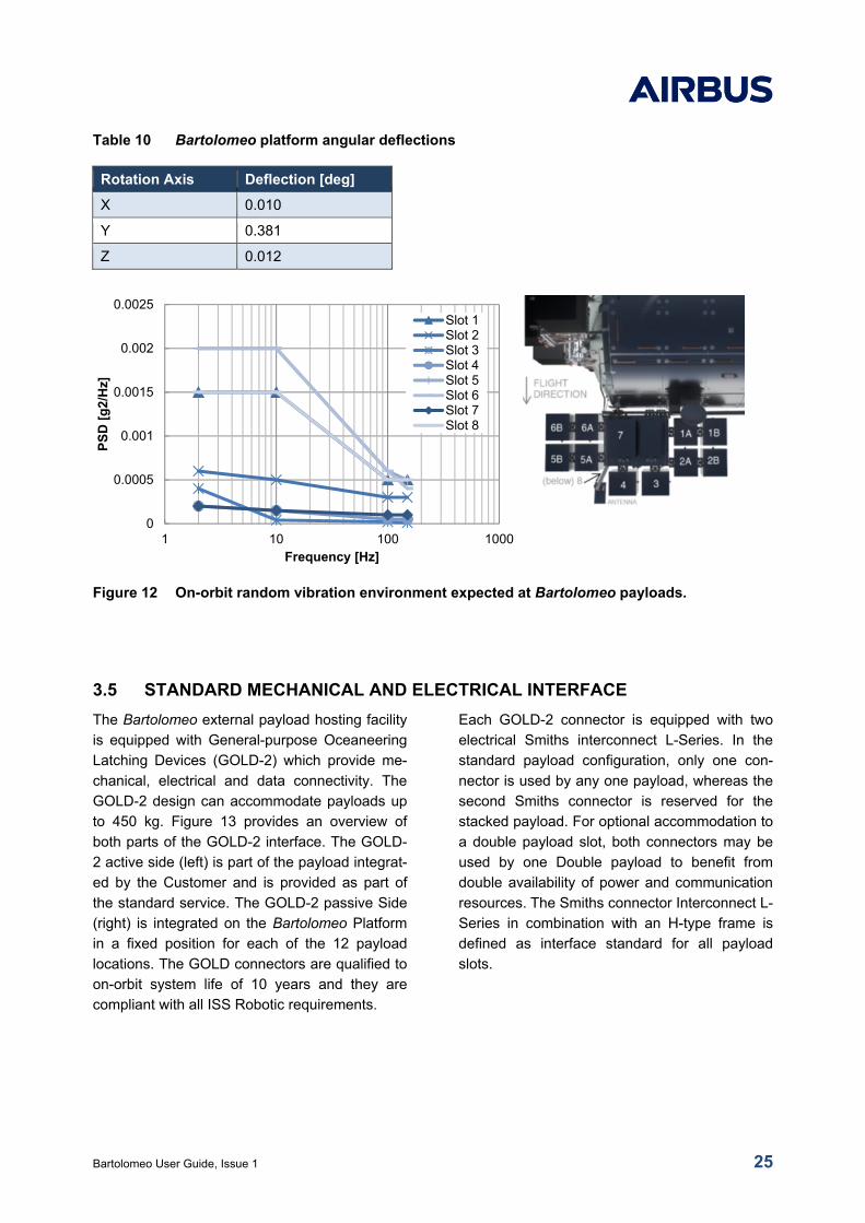
Figure 12 On-orbit random vibration environment expected at Bartolomeo payloads. ....................... 25
Figure 13 General-purpose Oceaneering Latching Device (GOLD-2) ................................................. 26
Figure 14 ArgUS payload in the JEM A/L envelope (example) ............................................................ 27
Figure 15 Bartolomeo avionics system overview ................................................................................. 28
Figure 16 Bartolomeo communication architecture ............................................................................. 28
Figure 17 Bartolomeo cloud as part of the AirCloud ............................................................................ 30
Figure 18 Communication between Space and Ground Segment....................................................... 31
Figure 19 AirCloud web portal (example layout and example data) .................................................... 32
Figure 20 Payload life cycle ................................................................................................................. 34
Figure 21 Unpressurized payload launch in ISS visiting vehicle trunk ................................................ 36
Figure 22 Pressurized payload launch in ISS visiting vehicle pressurized compartment .................... 37
Figure 23 ISS Dextre (SPDM) on the ISS ............................................................................................ 38
Bartolomeo User Guide, Issue 1 6
List of Tables
Table 1 Example missions ................................................................................................................ 13
Table 2 Standard service scope ....................................................................................................... 15
Table 3 Optional add-on service elements ....................................................................................... 15
Table 4 Payload mission preparation schedule and tasks ................................................................ 16
Table 5 Specific payload slot capabilities ......................................................................................... 18
Table 6 Payload sizes, budgets and resources ............................................................................. 19
Table 7 ISS orbit parameters ............................................................................................................ 23
Table 8 ISS flight attitudes ................................................................................................................ 24
Table 9 Pointing performance under the influence of jitter motions ................................................. 24
Table 10 Bartolomeo platform angular deflections ............................................................................. 25
Table 11 Relevant payload options ..................................................................................................... 35
Table 12 Launch static load environment ........................................................................................... 42
Table 13 Launch random vibration environment. ............................................................................... 42
Table 14 Expected thermal environments .......................................................................................... 43
Table 15 Thermal environment parameters ........................................................................................ 43
Table 16 Typical hazard controls ........................................................................................................ 45
Bartolomeo User Guide, Issue 1 7
List of Abbreviations
A/L Airlock payload Bartolomeo Customer Payload BOM Bill of Materials BTL BartolomeoCASIS Center for the Advancement of Science in Space CC Control Center C&M Command and Monitoring CoFR Certification of Flight Readiness CoG Center of Gravity COL ColumbusCOL-CC Columbus Control Center COMMS Communication System CONOPS Concept of Operations CTB Cargo Transfer Bag DHS Data Handling System DMS Data Management System EMC Electro-magnetic Compatibility EMI Electro-magnetic Interference ESA European Space Agency ESD Electrostatic Discharge EVA Extravehicular Activity EVR Extravehicular Robotics FRAM Flight Releasable Attachment Mechanism GOLD-2 General-purpose Oceaneering Latching Device 2 ICD Interface Control Document ICA Interface Control Agreement IP Internet Protocol IPR Intellectual Property Rights ISS International Space Station IVA Intravehicular Activity JAXA Japan Aerospace Exploration Agency JEM Japanese Experiment Module JEM-A/L Japanese Experiment Module Airlock JOTI JEM ORU Transfer Interface LAN Local Access Network LCT Laser Communication Terminal LEO Low Earth Orbit LVLH Local Vertical Local Horizontal MEVR Maximum Effective Vent Ratio MoI Moment of Inertia MPCC (Columbus) Multi-Purpose Computer & Communication system N/A Not Applicable NASA National Aeronautics & Space Administration NRAL NanoRacks Airlock OGS Optical Ground Station OPS Operations OSS Oceaneering Space Systems, Inc. OTCM ORU / Tool Change out Mechanism PDCU Power Distribution & Control Unit
Bartolomeo User Guide, Issue 1 8
P/L Payload PSD Power Spectral Density RH Relative Humidity RMS Remote Manipulator System SPDM Special Purpose Dexterous Manipulator SME Small and Medium Enterprise SRA Slot Reservation Agreement SSRMS Space Station Robotic Manipulation System TBC To Be Confirmed TBD To Be Determined TC Tele Command TDRS Tracking & Data Relays Satellite TDRSS Tracking & Data Relays Satellite Service TEA Torque Equilibrium Attitude TM/TC Telemetry and Telecommand TMM Thermal Mathematical Model USOS United States Orbital Segment VPN Virtual Private Network XCMU (Columbus) External Command & Monitoring Unit
Bartolomeo User Guide, Issue 1 9
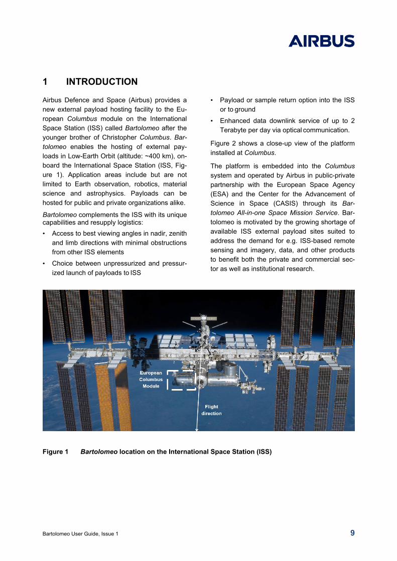
1 INTRODUCTION
Airbus Defence and Space (Airbus) provides a
new external payload hosting facility to the Eu-
ropean Columbus module on the International
Space Station (ISS) called Bartolomeo after the
younger brother of Christopher Columbus. Bar-
tolomeo enables the hosting of external pay-
loads in Low-Earth Orbit (altitude: ~400 km), on-
board the International Space Station (ISS, Fig-
ure 1). Application areas include but are not
limited to Earth observation, robotics, material
science and astrophysics. Payloads can be
hosted for public and private organizations alike.
Bartolomeo complements the ISS with its unique capabilities and resupply logistics:
• Access to best viewing angles in nadir, zenith
and limb directions with minimal obstructions
from other ISS elements
• Choice between unpressurized and pressur-
ized launch of payloads to ISS
• Payload or sample return option into the ISS
or to ground
• Enhanced data downlink service of up to 2
Terabyte per day via optical communication.
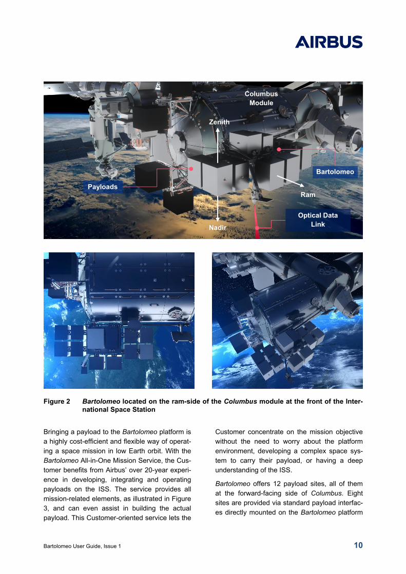
Figure 2 shows a close-up view of the platform
installed at Columbus.
The platform is embedded into the Columbus
system and operated by Airbus in public-private
partnership with the European Space Agency
(ESA) and the Center for the Advancement of
Science in Space (CASIS) through its Bar-
tolomeo All-in-one Space Mission Service. Bar-
tolomeo is motivated by the growing shortage of
available ISS external payload sites suited to
address the demand for e.g. ISS-based remote
sensing and imagery, data, and other products
to benefit both the private and commercial sec-
tor as well as institutional research.
[Image Credit: NASA]
Figure 1 Bartolomeo location on the International Space Station (ISS)
Bartolomeo User Guide, Issue 1 10
Figure 2 Bartolomeo located on the ram-side of the Columbus module at the front of the Inter-national Space Station
Bringing a payload to the Bartolomeo platform is
a highly cost-efficient and flexible way of operat-
ing a space mission in low Earth orbit. With the
Bartolomeo All-in-One Mission Service, the Cus-
tomer benefits from Airbus’ over 20-year experi-
ence in developing, integrating and operating
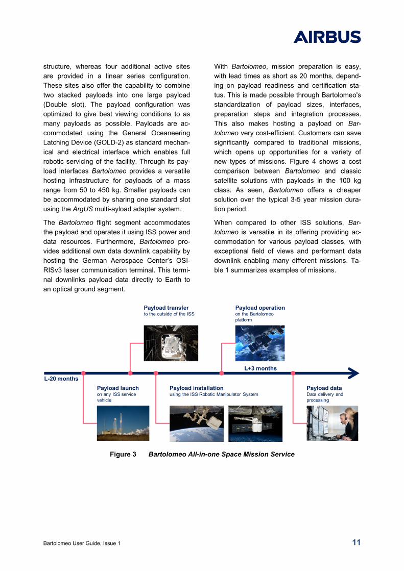
payloads on the ISS. The service provides all
mission-related elements, as illustrated in Figure
3, and can even assist in building the actual
payload. This Customer-oriented service lets the
Customer concentrate on the mission objective
without the need to worry about the platform
environment, developing a complex space sys-
tem to carry their payload, or having a deep
understanding of the ISS.
Bartolomeo offers 12 payload sites, all of them
at the forward-facing side of Columbus. Eight
sites are provided via standard payload interfac-
es directly mounted on the Bartolomeo platform
Payloads
Optical Data Link
Columbus Module
Bartolomeo
Zenith
Nadir
Ram
Bartolomeo User Guide, Issue 1 11
structure, whereas four additional active sites
are provided in a linear series configuration.
These sites also offer the capability to combine
two stacked payloads into one large payload
(Double slot). The payload configuration was
optimized to give best viewing conditions to as
many payloads as possible. Payloads are ac-
commodated using the General Oceaneering
Latching Device (GOLD-2) as standard mechan-
ical and electrical interface which enables full
robotic servicing of the facility. Through its pay-
load interfaces Bartolomeo provides a versatile
hosting infrastructure for payloads of a mass
range from 50 to 450 kg. Smaller payloads can
be accommodated by sharing one standard slot
using the ArgUS multi-ayload adapter system.
The Bartolomeo flight segment accommodates
the payload and operates it using ISS power and
data resources. Furthermore, Bartolomeo pro-
vides additional own data downlink capability by
hosting the German Aerospace Center’s OSI-
RISv3 laser communication terminal. This termi-
nal downlinks payload data directly to Earth to
an optical ground segment.
With Bartolomeo, mission preparation is easy,
with lead times as short as 20 months, depend-
ing on payload readiness and certification sta-
tus. This is made possible through Bartolomeo's
standardization of payload sizes, interfaces,
preparation steps and integration processes.
This also makes hosting a payload on Bar-
tolomeo very cost-efficient. Customers can save
significantly compared to traditional missions,
which opens up opportunities for a variety of
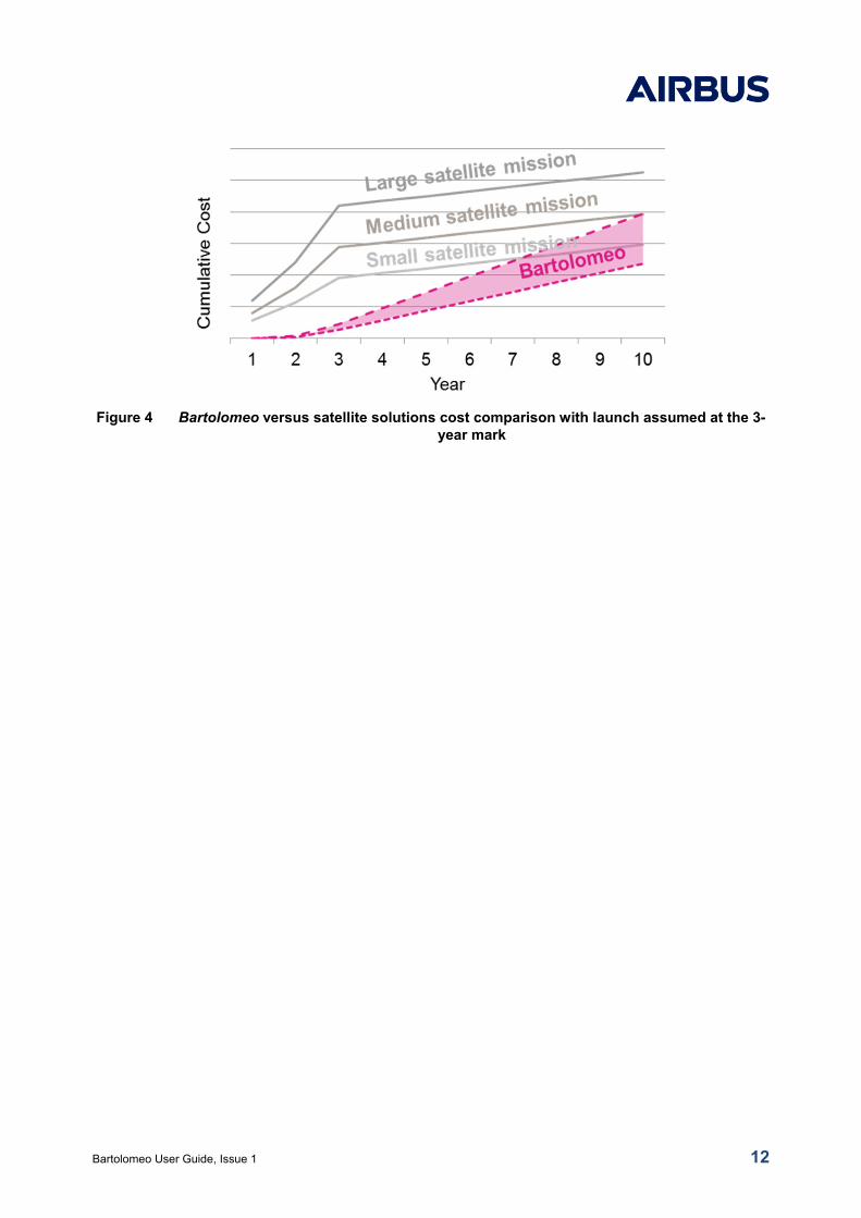
new types of missions. Figure 4 shows a cost
comparison between Bartolomeo and classic
satellite solutions with payloads in the 100 kg
class. As seen, Bartolomeo offers a cheaper
solution over the typical 3-5 year mission dura-
tion period.
When compared to other ISS solutions, Bar-
tolomeo is versatile in its offering providing ac-
commodation for various payload classes, with
exceptional field of views and performant data
downlink enabling many different missions. Ta-
ble 1 summarizes examples of missions.
Figure 3 Bartolomeo All-in-one Space Mission Service
Bartolomeo User Guide, Issue 1 12
Figure 4 Bartolomeo versus satellite solutions cost comparison with launch assumed at the 3-year mark
Bartolomeo User Guide, Issue 1 13
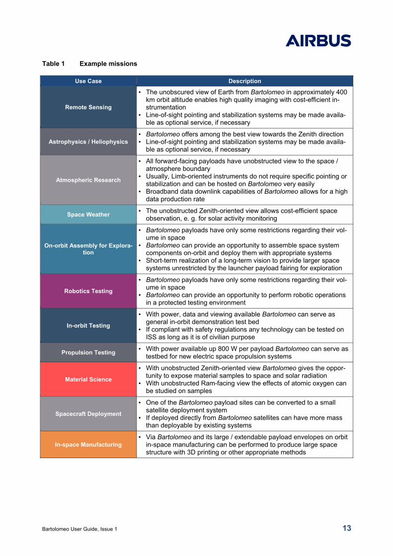
Table 1 Example missions
Use Case Description
Remote Sensing
• The unobscured view of Earth from Bartolomeo in approximately 400 km orbit altitude enables high quality imaging with cost-efficient in-strumentation
• Line-of-sight pointing and stabilization systems may be made availa-ble as optional service, if necessary
Astrophysics / Heliophysics • Bartolomeo offers among the best view towards the Zenith direction • Line-of-sight pointing and stabilization systems may be made availa-
ble as optional service, if necessary
Atmospheric Research
• All forward-facing payloads have unobstructed view to the space / atmosphere boundary
• Usually, Limb-oriented instruments do not require specific pointing or stabilization and can be hosted on Bartolomeo very easily
• Broadband data downlink capabilities of Bartolomeo allows for a high data production rate
Space Weather • The unobstructed Zenith-oriented view allows cost-efficient space
observation, e. g. for solar activity monitoring
On-orbit Assembly for Explora-tion
• Bartolomeo payloads have only some restrictions regarding their vol-ume in space
• Bartolomeo can provide an opportunity to assemble space system components on-orbit and deploy them with appropriate systems
• Short-term realization of a long-term vision to provide larger space systems unrestricted by the launcher payload fairing for exploration
Robotics Testing
• Bartolomeo payloads have only some restrictions regarding their vol-ume in space
• Bartolomeo can provide an opportunity to perform robotic operations in a protected testing environment
In-orbit Testing
• With power, data and viewing available Bartolomeo can serve as general in-orbit demonstration test bed
• If compliant with safety regulations any technology can be tested on ISS as long as it is of civilian purpose
Propulsion Testing • With power available up 800 W per payload Bartolomeo can serve as
testbed for new electric space propulsion systems
Material Science
• With unobstructed Zenith-oriented view Bartolomeo gives the oppor-tunity to expose material samples to space and solar radiation
• With unobstructed Ram-facing view the effects of atomic oxygen can be studied on samples
Spacecraft Deployment
• One of the Bartolomeo payload sites can be converted to a small satellite deployment system
• If deployed directly from Bartolomeo satellites can have more mass than deployable by existing systems
In-space Manufacturing • Via Bartolomeo and its large / extendable payload envelopes on orbit
in-space manufacturing can be performed to produce large space structure with 3D printing or other appropriate methods
Bartolomeo User Guide, Issue 1 14
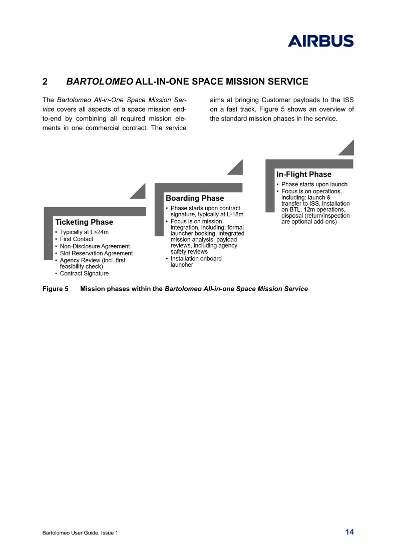
2 BARTOLOMEO ALL-IN-ONE SPACE MISSION SERVICE
The Bartolomeo All-in-One Space Mission Ser-
vice covers all aspects of a space mission end-
to-end by combining all required mission ele-
ments in one commercial contract. The service
aims at bringing Customer payloads to the ISS
on a fast track. Figure 5 shows an overview of
the standard mission phases in the service.
Figure 5 Mission phases within the Bartolomeo All-in-one Space Mission Service
Bartolomeo User Guide, Issue 1 15
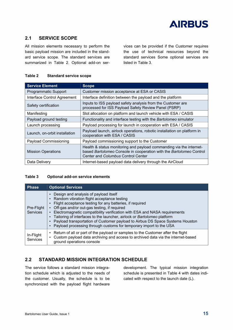
2.1 SERVICE SCOPE
All mission elements necessary to perform the
basic payload mission are included in the stand-
ard service scope. The standard services are
summarized in Table 2. Optional add-on ser-
vices can be provided if the Customer requires
the use of technical resources beyond the
standard services Some optional services are
listed in Table 3.
Table 2 Standard service scope
Service Element Scope
Programmatic Support Customer mission acceptance at ESA or CASIS
Interface Control Agreement Interface definition between the payload and the platform
Safety certification Inputs to ISS payload safety analysis from the Customer are processed for ISS Payload Safety Review Panel (PSRP)
Manifesting Slot allocation on platform and launch vehicle with ESA / CASIS
Payload ground testing Functionality and interface testing with the Bartolomeo simulator
Launch processing Payload processing for launch in cooperation with ESA / CASIS
Launch, on-orbit installation Payload launch, airlock operations, robotic installation on platform in cooperation with ESA / CASIS
Payload Commissioning Payload commissioning support to the Customer
Mission Operations Health & status monitoring and payload commanding via the internet-based Bartolomeo Console in cooperation with the Bartolomeo Control Center and Columbus Control Center
Data Delivery Internet-based payload data delivery through the AirCloud
Table 3 Optional add-on service elements
Phase Optional Services
Pre-Flight Services
• Design and analysis of payload itself • Random vibration flight acceptance testing • Flight acceptance testing for any batteries, if required • Off-gas and/or out-gas testing, if required • Electromagnetic compatibility verification with ESA and NASA requirements • Tailoring of interfaces to the launcher, airlock or Bartolomeo platform • Payload transportation of Customer payload to Airbus DS Space Systems Houston • Payload processing through customs for temporary import to the USA
In-Flight Services
• Return of all or part of the payload or samples to the Customer after the flight • Custom payload data archiving and access to archived data via the internet-based
ground operations console
2.2 STANDARD MISSION INTEGRATION SCHEDULE
The service follows a standard mission integra-
tion schedule which is adjusted to the needs of
the customer. Usually, the schedule is to be
synchronized with the payload flight hardware
development. The typical mission integration
schedule is presented in Table 4 with dates indi-
cated with respect to the launch date (L).
Bartolomeo User Guide, Issue 1 16
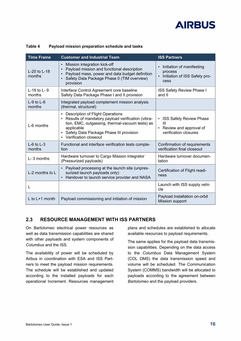
Table 4 Payload mission preparation schedule and tasks
Time Frame Customer and Industrial Team ISS Partners
L-20 to L-18 months
• Mission integration kick-off • Payload mission and functional description • Payload mass, power and data budget definition • Safety Data Package Phase 0 (TIM overview)
provision
• Initiation of manifesting process
• Initiation of ISS Safety pro-cess
L-18 to L- 9 months
Interface Control Agreement core baseline Safety Data Package Phase I and II provision
ISS Safety Review Phase I and II
L-9 to L-6 months
Integrated payload complement mission analysis (thermal, structural)
L-6 months
• Description of Flight Operations • Results of mandatory payload verification (vibra-
tion, EMC, outgassing, thermal-vacuum tests) as applicable
• Safety Data Package Phase III provision • Verification closeout
• ISS Safety Review Phase III
• Review and approval of verification closures
L-6 to L-3 months
Functional and interface verification tests comple-tion
Confirmation of requirements verification final closeout
L- 3 months Hardware turnover to Cargo Mission integrator (Pressurized payloads)
Hardware turnover documen-tation
L-2 months to L • Payload processing at the launch site (unpres-
surized launch payloads only) • Handover to launch service provider and NASA
Certification of Flight readi-ness
L Launch with ISS supply vehi-cle
L to L+1 month Payload commissioning and initiation of mission Payload installation on-orbit Mission support
2.3 RESOURCE MANAGEMENT WITH ISS PARTNERS
On Bartolomeo electrical power resources as
well as data transmission capabilities are shared
with other payloads and system components of
Columbus and the ISS.
The availability of power will be scheduled by
Airbus in coordination with ESA and ISS Part-
ners to meet the payload mission requirements.
The schedule will be established and updated
according to the installed payloads for each
operational Increment. Resources management
plans and schedules are established to allocate
available resources to payload requirements.
The same applies for the payload data transmis-
sion capabilities. Depending on the data access
to the Columbus Data Management System
(COL DMS) the data transmission speed and
volume will be scheduled. The Communication
System (COMMS) bandwidth will be allocated to
payloads according to the agreement between
Bartolomeo and the payload providers.
Bartolomeo User Guide, Issue 1 17
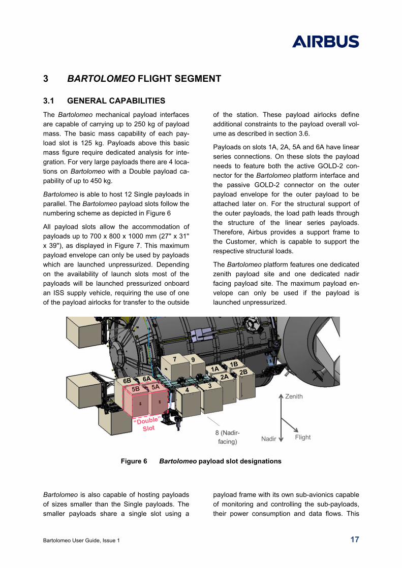
3 BARTOLOMEO FLIGHT SEGMENT
3.1 GENERAL CAPABILITIES
The Bartolomeo mechanical payload interfaces
are capable of carrying up to 250 kg of payload
mass. The basic mass capability of each pay-
load slot is 125 kg. Payloads above this basic
mass figure require dedicated analysis for inte-
gration. For very large payloads there are 4 loca-
tions on Bartolomeo with a Double payload ca-
pability of up to 450 kg.
Bartolomeo is able to host 12 Single payloads in
parallel. The Bartolomeo payload slots follow the
numbering scheme as depicted in Figure 6
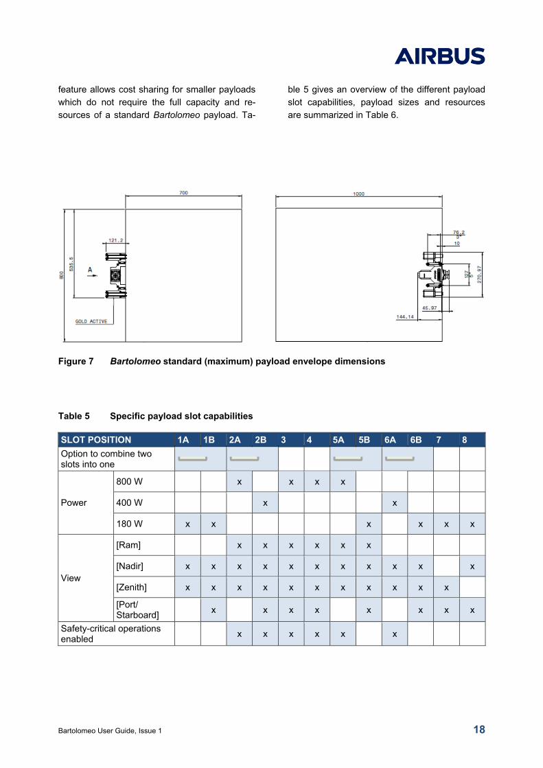
All payload slots allow the accommodation of
payloads up to 700 x 800 x 1000 mm (27'' x 31''
x 39''), as displayed in Figure 7. This maximum
payload envelope can only be used by payloads
which are launched unpressurized. Depending
on the availability of launch slots most of the
payloads will be launched pressurized onboard
an ISS supply vehicle, requiring the use of one
of the payload airlocks for transfer to the outside
of the station. These payload airlocks define
additional constraints to the payload overall vol-
ume as described in section 3.6.
Payloads on slots 1A, 2A, 5A and 6A have linear
series connections. On these slots the payload
needs to feature both the active GOLD-2 con-
nector for the Bartolomeo platform interface and
the passive GOLD-2 connector on the outer
payload envelope for the outer payload to be
attached later on. For the structural support of
the outer payloads, the load path leads through
the structure of the linear series payloads.
Therefore, Airbus provides a support frame to
the Customer, which is capable to support the
respective structural loads.
The Bartolomeo platform features one dedicated
zenith payload site and one dedicated nadir
facing payload site. The maximum payload en-
velope can only be used if the payload is
launched unpressurized.
Figure 6 Bartolomeo payload slot designations
Bartolomeo is also capable of hosting payloads
of sizes smaller than the Single payloads. The
smaller payloads share a single slot using a
payload frame with its own sub-avionics capable
of monitoring and controlling the sub-payloads,
their power consumption and data flows. This
Bartolomeo User Guide, Issue 1 18
feature allows cost sharing for smaller payloads
which do not require the full capacity and re-
sources of a standard Bartolomeo payload. Ta-
ble 5 gives an overview of the different payload
slot capabilities, payload sizes and resources
are summarized in Table 6.
Figure 7 Bartolomeo standard (maximum) payload envelope dimensions
Table 5 Specific payload slot capabilities
SLOT POSITION 1A 1B 2A 2B 3 4 5A 5B 6A 6B 7 8
Option to combine two slots into one
Power
800 W x x x x
400 W x x
180 W x x x x x x
View
[Ram]
x x x x x x
[Nadir] x x x x x x x x x x
x
[Zenith] x x x x x x x x x x x
[Port/ Starboard]
x
x x x
x
x x x
Safety-critical operations enabled
x x x x x x
Bartolomeo User Guide, Issue 1 19
Table 6 Payload sizes, budgets and resources
Item Single Payload Slot Double Payload Slot ArgUS Accommodation
Standard Service
Geometric envelope
up to 1000 x 800 x 800 mm
up to 1000 x 800 x 1600 mm
up to 356 x 300 x 1000 mm or 392 x 300 x 1000 mm
Payload Mass 125 kg nominal[1] 250 kg nominal[1] up to 450 kg maximum
Not specified
Power (operation-al)
120 VDC 180, 400 , and 800 W[2]
120 VDC up to 2x800 W[2]
28 VDC up to 140 W
Power (survival) 120 VDC limited to 20 W 120 VDC limited to 40 W 28 VDC up to 20 W
Data downlink 0.1 - 1 Mbit / s 0.2 - 2 Mbit / s 0.1 - 1 Mbit / s
Commanding and Monitoring
Near Real time through Columbus
Robotic interface (mechanical)
included in the standard payload interface N/A
Optional Service
Return capability Yes, if airlock compatible size
No Yes
Enhanced data downlink
2 TB / day via laser terminal
Robotic interface (electrical)
to be included into the payload
Notes: [1] Overall payload mass budget of the platform to be taken into account [2] Depending on availability and location The Bartolomeo platform also provides three
locations equipped with a coax cable which is
routed to the inside of the Columbus module.
These locations can be utilized for antennae and
provide a robotically compatible GOLD 2 con-
nector. Facilities utilizing these antennae would
typically be installed in the interior volume of the
Columbus module. Use of this feature requires a
unique Customer agreement with the European
Space Agency facilitated by Airbus.
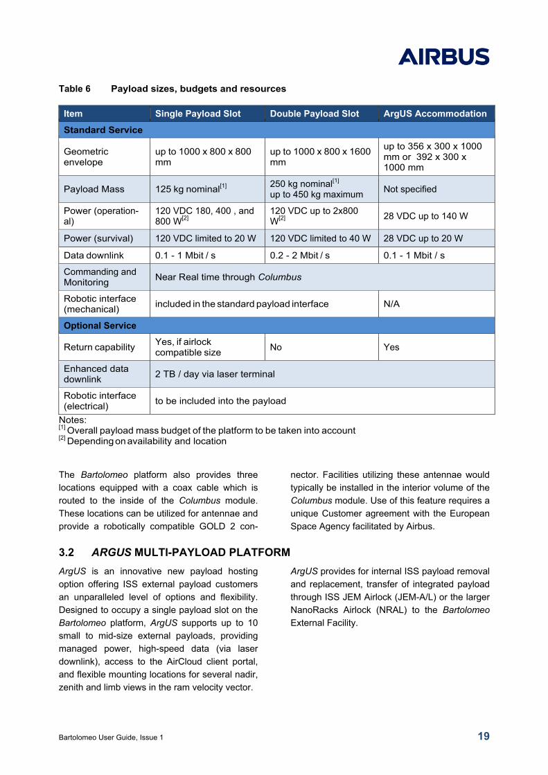
3.2 ARGUS MULTI-PAYLOAD PLATFORM
ArgUS is an innovative new payload hosting
option offering ISS external payload customers
an unparalleled level of options and flexibility.
Designed to occupy a single payload slot on the
Bartolomeo platform, ArgUS supports up to 10
small to mid-size external payloads, providing
managed power, high-speed data (via laser
downlink), access to the AirCloud client portal,
and flexible mounting locations for several nadir,
zenith and limb views in the ram velocity vector.
ArgUS provides for internal ISS payload removal
and replacement, transfer of integrated payload
through ISS JEM Airlock (JEM-A/L) or the larger
NanoRacks Airlock (NRAL) to the Bartolomeo
External Facility.
Bartolomeo User Guide, Issue 1 20
Figure 8 ArgUS payload platform
The ArgUS mechanical plate standard dimen-
sions are 476 mm x 700 mm, however it also
allows certain overhang of payloads, restricted
by the maximum available airlock envelope.
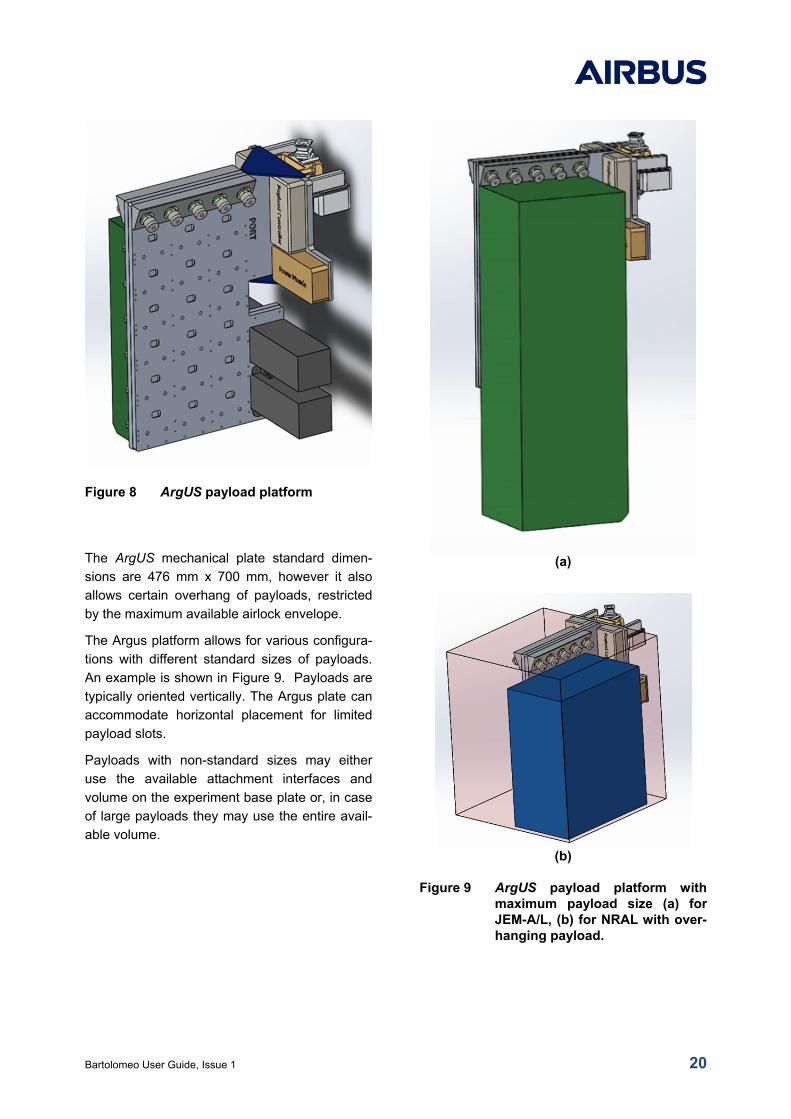
The Argus platform allows for various configura-
tions with different standard sizes of payloads.
An example is shown in Figure 9. Payloads are
typically oriented vertically. The Argus plate can
accommodate horizontal placement for limited
payload slots.
Payloads with non-standard sizes may either
use the available attachment interfaces and
volume on the experiment base plate or, in case
of large payloads they may use the entire avail-
able volume.
(a)
(b)
Figure 9 ArgUS payload platform with maximum payload size (a) for JEM-A/L, (b) for NRAL with over-hanging payload.
Bartolomeo User Guide, Issue 1 21
3.2.1 ARGUS PAYLOAD POWER
Electrical services are available via 10 ArgUS
payload interface connectors. The connectors
are located at the upper side of the base-plate.
The interface to the payload provides a switcha-
ble 28 VDC power outlet with a maximum power
dependent on the size of each payload. Total
power available to all ArgUS payloads is 140
W/5A in a 180 W Bartolomeo payload location
(Table 5). The power allocation is to be divided
between all ArgUS payloads to be accommo-
dated in a mission specific configuration. If other
slot locations are allocated to ArgUS, higher
power can be provided to ArgUS payloads ac-
cordingly.
3.2.2 ARGUS COMMANDING AND DATA HANDLING
The ArgUS platform has a payload control com-
puter onboard. Along with a power control mod-
ule, ArgUS handles all communications and
manages power for all experiments. All com-
manding is handled through a simple TCP pro-
tocol. Health & Status and experiment payload
data is transferred to the ArgUS payload control-
ler using TCP and UDP protocols and streams.
The ArgUS payload controller communicates
directly with the Bartolomeo DHS using a TCP
message bus. The ArgUS payload controller
enables transferring data to the AirCloud for
client use. The AirCloud environment allows
ArgUS-based experiments to command, control
and transfer data and scripts between the
ground and the experiment on the ArgUS plat-
form.
Bartolomeo User Guide, Issue 1 22
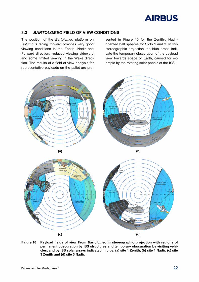
3.3 BARTOLOMEO FIELD OF VIEW CONDITIONS
The position of the Bartolomeo platform on
Columbus facing forward provides very good
viewing conditions in the Zenith, Nadir and
Forward direction, reduced viewing sideward
and some limited viewing in the Wake direc-
tion. The results of a field of view analysis for
representative payloads on the pallet are pre-
sented in Figure 10 for the Zenith-, Nadir-
oriented half spheres for Slots 1 and 3. In this
stereographic projection the blue areas indi-
cate the temporary obscuration of the payload
view towards space or Earth, caused for ex-
ample by the rotating solar panels of the ISS.
(a) (b)
(c) (d)
Figure 10 Payload fields of view From Bartolomeo in stereographic projection with regions of permanent obscuration by ISS structures and temporary obscuration by visiting vehi-cles, and by ISS solar arrays indicated in blue, (a) site 1 Zenith, (b) site 1 Nadir, (c) site 3 Zenith and (d) site 3 Nadir.
Bartolomeo User Guide, Issue 1 23
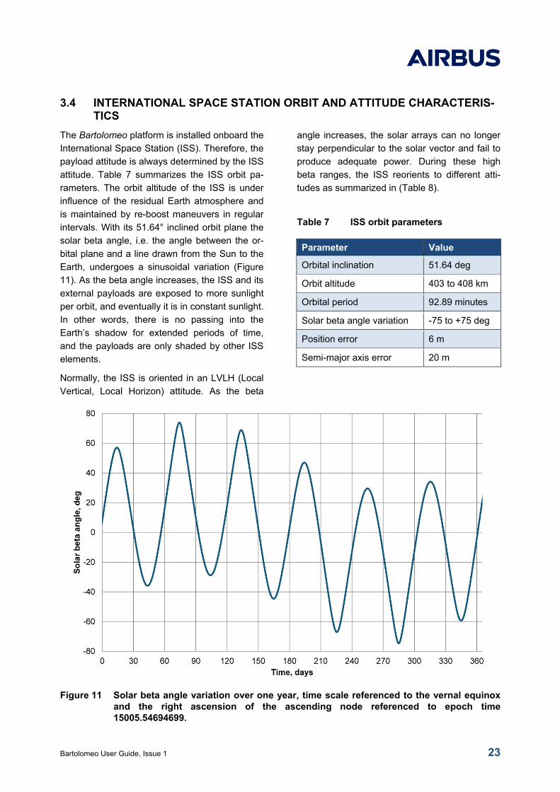
3.4 INTERNATIONAL SPACE STATION ORBIT AND ATTITUDE CHARACTERIS-TICS
The Bartolomeo platform is installed onboard the
International Space Station (ISS). Therefore, the
payload attitude is always determined by the ISS
attitude. Table 7 summarizes the ISS orbit pa-
rameters. The orbit altitude of the ISS is under
influence of the residual Earth atmosphere and
is maintained by re-boost maneuvers in regular
intervals. With its 51.64° inclined orbit plane the
solar beta angle, i.e. the angle between the or-
bital plane and a line drawn from the Sun to the
Earth, undergoes a sinusoidal variation (Figure
11). As the beta angle increases, the ISS and its
external payloads are exposed to more sunlight
per orbit, and eventually it is in constant sunlight.
In other words, there is no passing into the
Earth’s shadow for extended periods of time,
and the payloads are only shaded by other ISS
elements.
Normally, the ISS is oriented in an LVLH (Local
Vertical, Local Horizon) attitude. As the beta
angle increases, the solar arrays can no longer
stay perpendicular to the solar vector and fail to
produce adequate power. During these high
beta ranges, the ISS reorients to different atti-
tudes as summarized in (Table 8).
Table 7 ISS orbit parameters
Parameter Value
Orbital inclination 51.64 deg
Orbit altitude 403 to 408 km
Orbital period 92.89 minutes
Solar beta angle variation -75 to +75 deg
Position error 6 m
Semi-major axis error 20 m
Figure 11 Solar beta angle variation over one year, time scale referenced to the vernal equinox and the right ascension of the ascending node referenced to epoch time 15005.54694699.
Bartolomeo User Guide, Issue 1 24
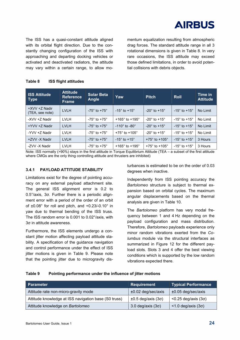
The ISS has a quasi-constant attitude aligned
with its orbital flight direction. Due to the con-
stantly changing configuration of the ISS with
approaching and departing docking vehicles or
activated and deactivated radiators, the attitude
may vary within a certain range, to allow mo-
mentum equalization resulting from atmospheric
drag forces. The standard attitude range in all 3
rotational dimensions is given in Table 8. In very
rare occasions, the ISS attitude may exceed
those defined limitations, in order to avoid poten-
tial collisions with debris objects.
Table 8 ISS flight attitudes
ISS Attitude Type
Attitude Reference Frame
Solar Beta Angle
Yaw Pitch Roll Time in Attitude
+XVV +Z Nadir (TEA, see note)
LVLH -75° to +75° -15° to +15° -20° to +15° -15° to +15° No Limit
-XVV +Z Nadir LVLH -75° to +75° +165° to +195° -20° to +15° -15° to +15° No Limit
+YVV +Z Nadir LVLH -75° to +75° -110° to -80° -20° to +15° -15° to +15° No Limit
-YVV +Z Nadir LVLH -75° to +75° +75° to +105° -20° to +15° -15° to +15° No Limit
+ZVV -X Nadir LVLH -75° to +75° -15° to +15° +75° to +105° -15° to +15° 3 Hours
-ZVV -X Nadir LVLH -75° to +75° +165° to +195° +75° to +105° -15° to +15° 3 Hours
Note: ISS normally (>90%) stays in the first attitude in Torque Equilibrium Attitude (TEA – a subset of the first attitude where CMGs are the only thing controlling attitude and thrusters are inhibited)
3.4.1 PAYLOAD ATTITUDE STABILITY
Limitations exist for the degree of pointing accu-
racy on any external payload attachment site.
The general ISS alignment error is 0.2 to
0.5°/axis, 3σ. Further there is a periodic align-
ment error with a period of the order of an orbit
of ±0.08° for roll and pitch, and +0.23/-0.10° in
yaw due to thermal bending of the ISS truss.
The ISS random error is 0.001 to 0.02°/axis, with
3σ in attitude awareness.
Furthermore, the ISS elements undergo a con-
stant jitter motion affecting payload attitude sta-
bility. A specification of the guidance navigation
and control performance under the effect of ISS
jitter motions is given in Table 9. Please note
that the pointing jitter due to microgravity dis-
turbances is estimated to be on the order of 0.03
degrees when inactive.
Independently from ISS pointing accuracy the
Bartolomeo structure is subject to thermal ex-
pansion based on orbital cycles. The maximum
angular displacements based on the thermal
analysis are given in Table 10.
The Bartolomeo platform has very modal fre-
quency between 1 and 4 Hz depending on the
payload configuration and mass distribution.
Therefore, Bartolomeo payloads experience only
minor random vibrations exerted from the Co-
lumbus module via the structural interfaces as
summarized in Figure 12 for the different pay-
load slots. Slots 3 and 4 offer the best viewing
conditions which is supported by the low random
vibrations expected there.
Table 9 Pointing performance under the influence of jitter motions
Parameter Requirement Typical Performance
Attitude rate non-micro-gravity mode ±0.02 deg/sec/axis ±0.05 deg/sec/axis
Attitude knowledge at ISS navigation base (S0 truss) ±0.5 deg/axis (3σ) <0.25 deg/axis (3σ)
Attitude knowledge on Bartolomeo 3.0 deg/axis (3σ) <1.0 deg/axis (3σ)
Bartolomeo User Guide, Issue 1 25
Table 10 Bartolomeo platform angular deflections
Rotation Axis Deflection [deg]
X 0.010
Y 0.381
Z 0.012
Figure 12 On-orbit random vibration environment expected at Bartolomeo payloads.
3.5 STANDARD MECHANICAL AND ELECTRICAL INTERFACE
The Bartolomeo external payload hosting facility
is equipped with General-purpose Oceaneering
Latching Devices (GOLD-2) which provide me-
chanical, electrical and data connectivity. The
GOLD-2 design can accommodate payloads up
to 450 kg. Figure 13 provides an overview of
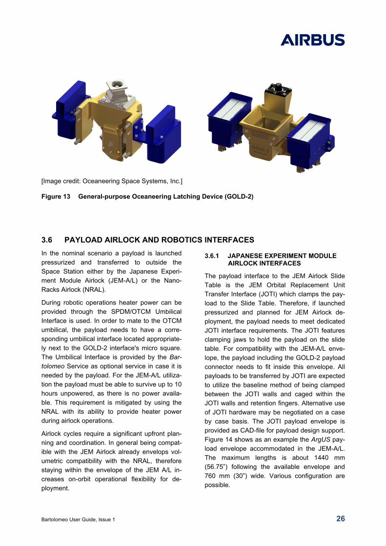
both parts of the GOLD-2 interface. The GOLD-
2 active side (left) is part of the payload integrat-
ed by the Customer and is provided as part of
the standard service. The GOLD-2 passive Side
(right) is integrated on the Bartolomeo Platform
in a fixed position for each of the 12 payload
locations. The GOLD connectors are qualified to
on-orbit system life of 10 years and they are
compliant with all ISS Robotic requirements.
Each GOLD-2 connector is equipped with two
electrical Smiths interconnect L-Series. In the
standard payload configuration, only one con-
nector is used by any one payload, whereas the
second Smiths connector is reserved for the
stacked payload. For optional accommodation to
a double payload slot, both connectors may be
used by one Double payload to benefit from
double availability of power and communication
resources. The Smiths connector Interconnect L-
Series in combination with an H-type frame is
defined as interface standard for all payload
slots.
0
0.0005
0.001
0.0015
0.002
0.0025
1 10 100 1000
PS
D [
g2/
Hz]
Frequency [Hz]
Slot 1Slot 2Slot 3Slot 4Slot 5Slot 6Slot 7Slot 8
Bartolomeo User Guide, Issue 1 26
[Image credit: Oceaneering Space Systems, Inc.]
Figure 13 General-purpose Oceaneering Latching Device (GOLD-2)
3.6 PAYLOAD AIRLOCK AND ROBOTICS INTERFACES
In the nominal scenario a payload is launched
pressurized and transferred to outside the
Space Station either by the Japanese Experi-
ment Module Airlock (JEM-A/L) or the Nano-
Racks Airlock (NRAL).
During robotic operations heater power can be
provided through the SPDM/OTCM Umbilical
Interface is used. In order to mate to the OTCM
umbilical, the payload needs to have a corre-
sponding umbilical interface located appropriate-
ly next to the GOLD-2 interface's micro square.
The Umbilical Interface is provided by the Bar-
tolomeo Service as optional service in case it is
needed by the payload. For the JEM-A/L utiliza-
tion the payload must be able to survive up to 10
hours unpowered, as there is no power availa-
ble. This requirement is mitigated by using the
NRAL with its ability to provide heater power
during airlock operations.
Airlock cycles require a significant upfront plan-
ning and coordination. In general being compat-
ible with the JEM Airlock already envelops vol-
umetric compatibility with the NRAL, therefore
staying within the envelope of the JEM A/L in-
creases on-orbit operational flexibility for de-
ployment.
3.6.1 JAPANESE EXPERIMENT MODULE AIRLOCK INTERFACES
The payload interface to the JEM Airlock Slide
Table is the JEM Orbital Replacement Unit
Transfer Interface (JOTI) which clamps the pay-
load to the Slide Table. Therefore, if launched
pressurized and planned for JEM Airlock de-
ployment, the payload needs to meet dedicated
JOTI interface requirements. The JOTI features
clamping jaws to hold the payload on the slide
table. For compatibility with the JEM-A/L enve-
lope, the payload including the GOLD-2 payload
connector needs to fit inside this envelope. All
payloads to be transferred by JOTI are expected
to utilize the baseline method of being clamped
between the JOTI walls and caged within the
JOTI walls and retention fingers. Alternative use
of JOTI hardware may be negotiated on a case
by case basis. The JOTI payload envelope is
provided as CAD-file for payload design support.
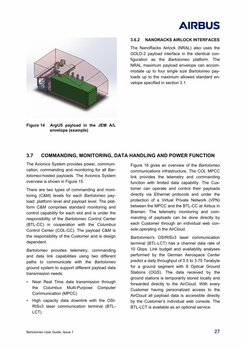
Figure 14 shows as an example the ArgUS pay-
load envelope accommodated in the JEM-A/L.
The maximum lengths is about 1440 mm
(56.75”) following the available envelope and
760 mm (30”) wide. Various configuration are
possible.
Bartolomeo User Guide, Issue 1 27
Figure 14 ArgUS payload in the JEM A/L envelope (example)
3.6.2 NANORACKS AIRLOCK INTERFACES
The NanoRacks Airlock (NRAL) also uses the
GOLD-2 payload interface in the identical con-
figuration as the Bartolomeo platform. The
NRAL maximum payload envelope can accom-
modate up to four single size Bartolomeo pay-
loads up to the maximum allowed standard en-
velope specified in section 3.1.
3.7 COMMANDING, MONITORING, DATA HANDLING AND POWER FUNCTION
The Avionics System provides power, communi-
cation, commanding and monitoring for all Bar-
tolomeo-hosted payloads. The Avionics System
overview is shown in Figure 15.
There are two types of commanding and moni-
toring (C&M) levels for each Bartolomeo pay-
load: platform level and payload level. The plat-
form C&M comprises standard monitoring and
control capability for each slot and is under the
responsibility of the Bartolomeo Control Center
(BTL-CC) in cooperation with the Columbus
Control Center (COL-CC). The payload C&M is
the responsibility of the Customer and is design
dependent.
Bartolomeo provides telemetry, commanding
and data link capabilities using two different
paths to communicate with the Bartolomeo
ground system to support different payload data
transmission needs:
• Near Real Time data transmission through
the Columbus Multi-Purpose Computer
Communication (MPCC)
• High capacity data downlink with the OSI-
RISv3 laser communication terminal (BTL-
LCT)
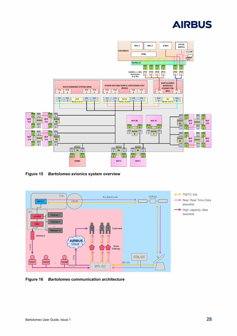
Figure 16 gives an overview of the Bartolomeo
communications infrastructure. The COL MPCC
link provides the telemetry and commanding
function with limited data capability. The Cus-
tomer can operate and control their payloads
directly via Ethernet protocols and under the
protection of a Virtual Private Network (VPN)
between the MPCC and the BTL-CC at Airbus in
Bremen. The telemetry monitoring and com-
manding of payloads can be done directly by
each Customer through an individual web con-
sole operating in the AirCloud.
Bartolomeo's OSIRISv3 laser communication
terminal (BTL-LCT) has a channel data rate of
10 Gbps. Link budget and availability analyses
performed by the German Aerospace Center
predict a daily throughput of 0.5 to 3.75 Terabyte
for a ground segment with 8 Optical Ground
Stations (OGS). The data received by the
ground stations is temporarily stored locally and
forwarded directly to the AirCloud. With every
Customer having personalized access to the
AirCloud all payload data is accessible directly
by the Customer’s individual web console. The
BTL-LCT is available as an optional service.
Bartolomeo User Guide, Issue 1 28
Figure 15 Bartolomeo avionics system overview
Figure 16 Bartolomeo communication architecture
Bartolomeo User Guide, Issue 1 29
3.7.1 COMMUNICATION FUNCTION
The Bartolomeo payload communication system
uses two networks onboard the platform: the
Payload Local Access Network (BTL-PL-LAN)
and the Payload Local Access Network (BTL-
COM-LAN). Payloads can decide either to dump
data to ground via the BTL-LCT or via the
MPCC using different subnet addresses. Pay-
load data sent to the BTL-LCT is buffered first in
the BTL-LCT mass memory before being
dumped to ground. Data transferred to the
MPCC is buffered in the MPCC attached drop
box and then automatically sent to ground via
the ISS link.
The BTL-PL-LAN is in any case used for moni-
toring and commanding of payloads.
3.7.2 POWER FUNCTION
The Bartolomeo platform routes power from
Columbus to all payload slots. The voltage of
power supply is 120 VDC with a nominal opera-
tional power provision of 180 W. Larger power
consumptions up to 800 W are possible. Be-
sides the operational power supply, all payload
locations have an additional survival heater
power supply of 20 W nominal at 120 VDC.
All interfaces have the same pin-out. The prima-
ry and survival heater power is distributed to
payloads in groups of five. A mono-stable relay
allows switching between payload power and
payload survival heater power. The relay control
is under the responsibility of platform operations
and affects one complete group. In case of BTL-
DHS power loss, the relay switches automatical-
ly to survival heating.
Bartolomeo User Guide, Issue 1 30
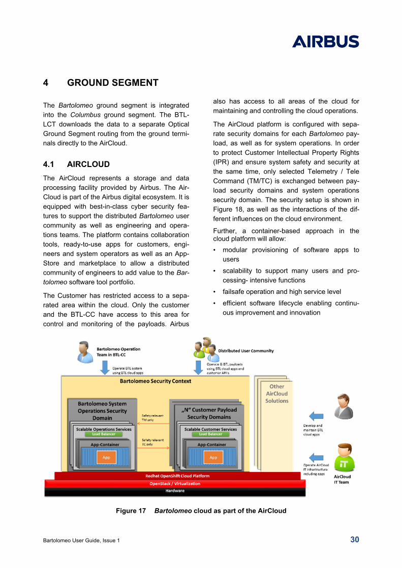
4 GROUND SEGMENT
The Bartolomeo ground segment is integrated
into the Columbus ground segment. The BTL-
LCT downloads the data to a separate Optical
Ground Segment routing from the ground termi-
nals directly to the AirCloud.
4.1 AIRCLOUD
The AirCloud represents a storage and data
processing facility provided by Airbus. The Air-
Cloud is part of the Airbus digital ecosystem. It is
equipped with best-in-class cyber security fea-
tures to support the distributed Bartolomeo user
community as well as engineering and opera-
tions teams. The platform contains collaboration
tools, ready-to-use apps for customers, engi-
neers and system operators as well as an App-
Store and marketplace to allow a distributed
community of engineers to add value to the Bar-
tolomeo software tool portfolio.
The Customer has restricted access to a sepa-
rated area within the cloud. Only the customer
and the BTL-CC have access to this area for
control and monitoring of the payloads. Airbus
also has access to all areas of the cloud for
maintaining and controlling the cloud operations.
The AirCloud platform is configured with sepa-
rate security domains for each Bartolomeo pay-
load, as well as for system operations. In order
to protect Customer Intellectual Property Rights
(IPR) and ensure system safety and security at
the same time, only selected Telemetry / Tele
Command (TM/TC) is exchanged between pay-
load security domains and system operations
security domain. The security setup is shown in
Figure 18, as well as the interactions of the dif-
ferent influences on the cloud environment.
Further, a container-based approach in the cloud platform will allow:
• modular provisioning of software apps to
users
• scalability to support many users and pro-
cessing- intensive functions
• failsafe operation and high service level
• efficient software lifecycle enabling continu-
ous improvement and innovation
Figure 17 Bartolomeo cloud as part of the AirCloud
Bartolomeo User Guide, Issue 1 31
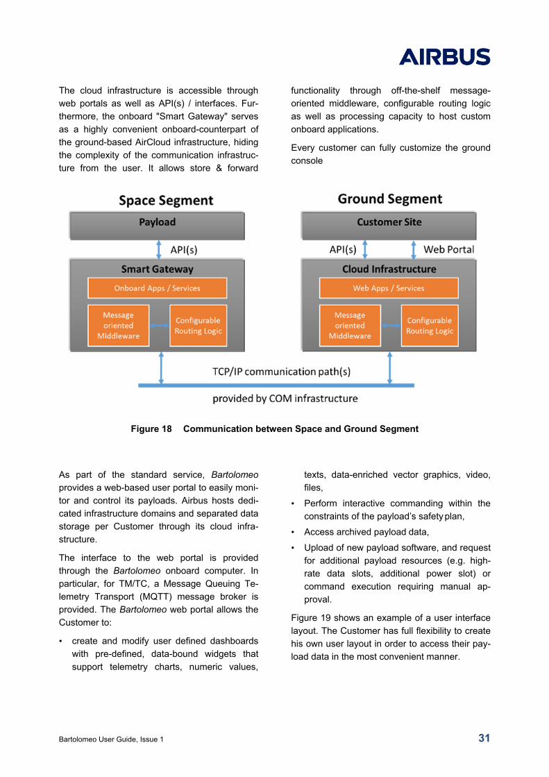
The cloud infrastructure is accessible through
web portals as well as API(s) / interfaces. Fur-
thermore, the onboard "Smart Gateway" serves
as a highly convenient onboard-counterpart of
the ground-based AirCloud infrastructure, hiding
the complexity of the communication infrastruc-
ture from the user. It allows store & forward
functionality through off-the-shelf message-
oriented middleware, configurable routing logic
as well as processing capacity to host custom
onboard applications.
Every customer can fully customize the ground
console
Figure 18 Communication between Space and Ground Segment
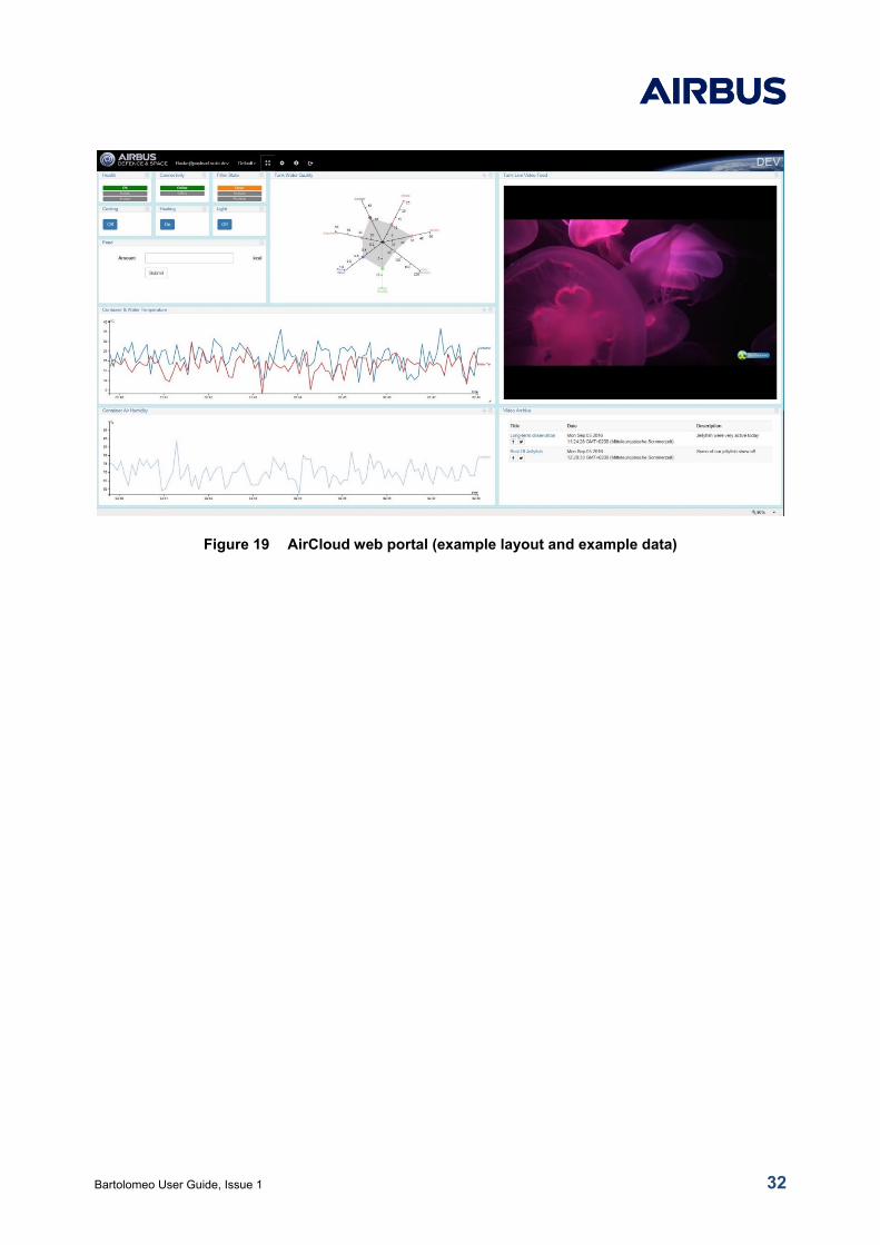
As part of the standard service, Bartolomeo
provides a web-based user portal to easily moni-
tor and control its payloads. Airbus hosts dedi-
cated infrastructure domains and separated data
storage per Customer through its cloud infra-
structure.
The interface to the web portal is provided
through the Bartolomeo onboard computer. In
particular, for TM/TC, a Message Queuing Te-
lemetry Transport (MQTT) message broker is
provided. The Bartolomeo web portal allows the
Customer to:
• create and modify user defined dashboards
with pre-defined, data-bound widgets that
support telemetry charts, numeric values,
texts, data-enriched vector graphics, video,
files,
• Perform interactive commanding within the
constraints of the payload’s safety plan,
• Access archived payload data,
• Upload of new payload software, and request
for additional payload resources (e.g. high-
rate data slots, additional power slot) or
command execution requiring manual ap-
proval.
Figure 19 shows an example of a user interface
layout. The Customer has full flexibility to create
his own user layout in order to access their pay-
load data in the most convenient manner.
Bartolomeo User Guide, Issue 1 32
Figure 19 AirCloud web portal (example layout and example data)
Bartolomeo User Guide, Issue 1 33
5 PAYLOAD LIFE CYCLE
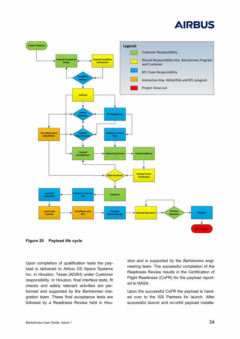
The payload processing is illustrated in Figure
20. Based on the payload conceptual baseline, a
feasibility analysis in combination with the Bar-
tolomeo facility is performed to analyze the pay-
load compatibility with the platform and ISS in-
terface and operational requirements. Upon
contract signature, the Bartolomeo program
organizes the suitable launch depending on the
payload needs and specifications as well as
availability in the ISS program. Based on the
launch manifest and the integration time line, the
Bartolomeo engineering team provides the pay-
load integration schedule and all interface re-
quirements as relevant for the payload devel-
opment.
The payload development itself is the responsi-
bility of the Customer. The following tests are
required as a minimum, details are agreed on
during the mission integration process:
• Vibration test to verify the structural margin of
the payload and the ensure launch survival
• Thermal test to verify the thermal ranges of
the payload, analysis may be sufficient in
specific cases.
• Electro-Magnetic Compatibility and Electro-
Static Discharge (EMC/ESD) test to validate
electromagnetic compatibility
• Functional tests to validate all functional re-
quirements of the payload
• Power quality and interface test
• Command and Data handling interface test
Portable test equipment is available to test the
payload interfaces to Bartolomeo, typically per-
formed shortly before hand-over. However, de-
pending on the particular payload may be ar-
ranged earlier at the payload developer site to
avoid late identification of interface issues.
Bartolomeo User Guide, Issue 1 34
Figure 20 Payload life cycle
Upon completion of qualification tests the pay-
load is delivered to Airbus DS Space Systems
Inc. in Houston, Texas (ADSH) under Customer
responsibility. In Houston, final interface tests, fit
checks and safety relevant activities are per-
formed and supported by the Bartolomeo inte-
gration team. These final acceptance tests are
followed by a Readiness Review held in Hou-
ston and is supported by the Bartolomeo engi-
neering team. The successful completion of the
Readiness Review results in the Certification of
Flight Readiness (CoFR) for the payload report-
ed to NASA.
Upon the successful CoFR the payload is hand-
ed over to the ISS Partners for launch. After
successful launch and on-orbit payload installa-
Bartolomeo User Guide, Issue 1 35
tion the payload is commissioned by the Cus-
tomer supported by the Bartolomeo team. As
soon as the nominal operation capability is es-
tablished the payload operations phase starts
with support from the Bartolomeo team in close
cooperation with the Customer. At the end of the
contractual life time the disposal phase is initiat-
ed. The standard disposal foresees the robotic
detachment of the payload from Bartolomeo and
reintegration into a visiting vehicle for destructive
re-entry. Payload or sample return is available
as optional service.
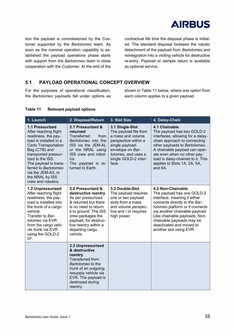
5.1 PAYLOAD OPERATIONAL CONCEPT OVERVIEW
For the purposes of operational classification,
the Bartolomeo payloads fall under options as
shown in Table 11 below, where one option from
each column applies to a given payload.
Table 11 Relevant payload options
1. Launch 2. Disposal/Return 3. Slot Size 4. Daisy-Chain
1.1 Pressurized After reaching flight readiness, the pay-load is installed in a Carto Transportation Bag (CTB) and transported pressur-ized to the ISS. The payload is trans-ferred to Bartolomeo via the JEM-A/L or the NRAL by ISS crew and robotics.
2.1 Pressurized & returned Transferred from Bartolomeo into the ISS via the JEM-AL or the NRAL using ISS crew and robot-ics The payload is re-turned to Earth.
3.1 Single-Slot The payload fits from a mass and volume perspective within a single payload-envelope on Bar-tolomeo, and uses a single GOLD-2 inter-face.
4.1 Chainable The payload has two GOLD-2 interfaces, allowing for a daisy-chain approach to connecting other payloads to Bartolomeo. A chainable payload can oper-ate even when no other pay-load is daisy-chained to it. This applies to Slots 1A, 2A, 5A, and 6A.
1.2 Unpressurized After reaching flight readiness, the pay-load is installed into the trunk of a cargo vehicle. Transfer to Bar-tolomeo via EVR from the cargo vehi-cle trunk via EVR using the GOLD-2 I/F.
2.2 Pressurized & destructive reentry As per pressurized & returned but there is no need to return it to ground. The ISS crew packages the payload, for destruc-tive reentry within a departing cargo vehicle.
3.2 Double-Slot The payload requires one or two payload slots from a mass and volume perspec-tive and / or requires high power.
4.2 Non-Chainable The payload has one GOLD-2 interface, meaning it either connects directly to the Bar-tolomeo platform or it connects via another chainable payload. Like chainable payloads, Non-chainable payloads may be deactivated and moved to another slot using EVR.
2.3 Unpressurised & destructive reentry Transferred from Bartolomeo to the trunk of an outgoing resupply vehicle via EVR. The payload is destroyed during reentry.
Bartolomeo User Guide, Issue 1 36
5.2 PAYLOAD LAUNCH OPTIONS
There are two principal options to launch a Bar-
tolomeo payload depending on its size and
mass properties.
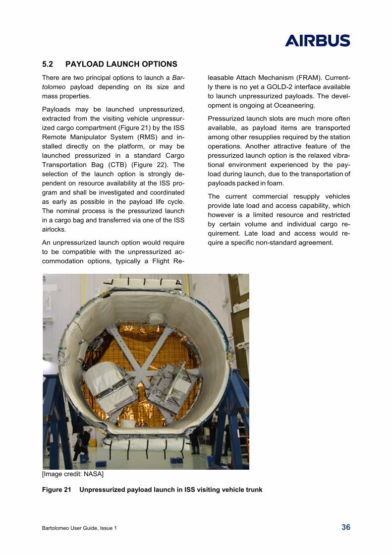
Payloads may be launched unpressurized,
extracted from the visiting vehicle unpressur-
ized cargo compartment (Figure 21) by the ISS
Remote Manipulator System (RMS) and in-
stalled directly on the platform, or may be
launched pressurized in a standard Cargo
Transportation Bag (CTB) (Figure 22). The
selection of the launch option is strongly de-
pendent on resource availability at the ISS pro-
gram and shall be investigated and coordinated
as early as possible in the payload life cycle.
The nominal process is the pressurized launch
in a cargo bag and transferred via one of the ISS
airlocks.
An unpressurized launch option would require
to be compatible with the unpressurized ac-
commodation options, typically a Flight Re-
leasable Attach Mechanism (FRAM). Current-
ly there is no yet a GOLD-2 interface available
to launch unpressurized payloads. The devel-
opment is ongoing at Oceaneering.
Pressurized launch slots are much more often
available, as payload items are transported
among other resupplies required by the station
operations. Another attractive feature of the
pressurized launch option is the relaxed vibra-
tional environment experienced by the pay-
load during launch, due to the transportation of
payloads packed in foam.
The current commercial resupply vehicles
provide late load and access capability, which
however is a limited resource and restricted
by certain volume and individual cargo re-
quirement. Late load and access would re-
quire a specific non-standard agreement.
[Image credit: NASA]
Figure 21 Unpressurized payload launch in ISS visiting vehicle trunk
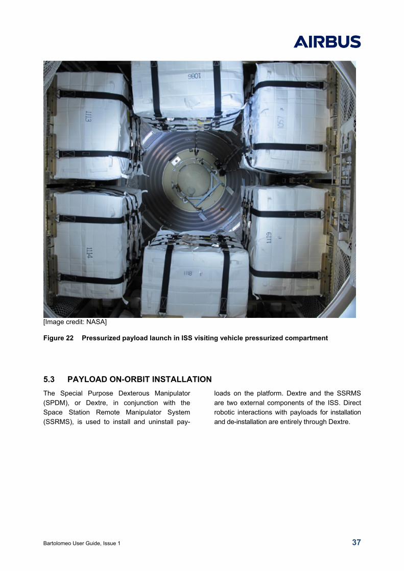
Bartolomeo User Guide, Issue 1 37
[Image credit: NASA]
Figure 22 Pressurized payload launch in ISS visiting vehicle pressurized compartment
5.3 PAYLOAD ON-ORBIT INSTALLATION
The Special Purpose Dexterous Manipulator
(SPDM), or Dextre, in conjunction with the
Space Station Remote Manipulator System
(SSRMS), is used to install and uninstall pay-
loads on the platform. Dextre and the SSRMS
are two external components of the ISS. Direct
robotic interactions with payloads for installation
and de-installation are entirely through Dextre.
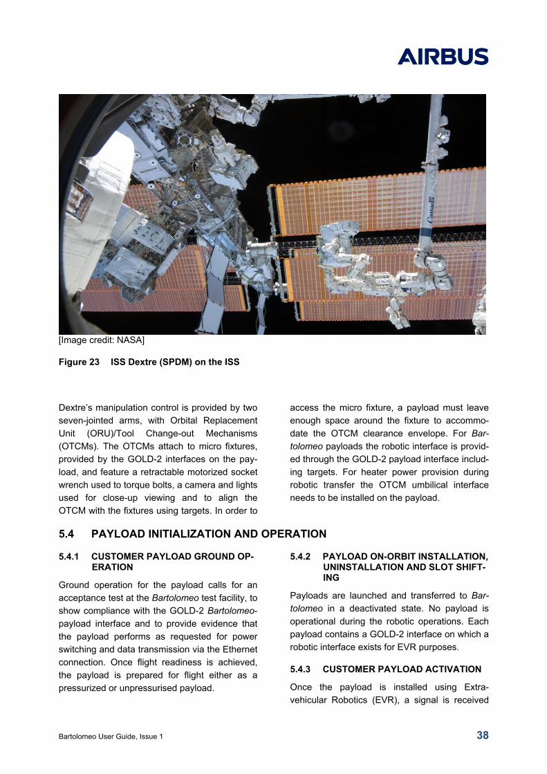
Bartolomeo User Guide, Issue 1 38
[Image credit: NASA]
Figure 23 ISS Dextre (SPDM) on the ISS
Dextre’s manipulation control is provided by two
seven-jointed arms, with Orbital Replacement
Unit (ORU)/Tool Change-out Mechanisms
(OTCMs). The OTCMs attach to micro fixtures,
provided by the GOLD-2 interfaces on the pay-
load, and feature a retractable motorized socket
wrench used to torque bolts, a camera and lights
used for close-up viewing and to align the
OTCM with the fixtures using targets. In order to
access the micro fixture, a payload must leave
enough space around the fixture to accommo-
date the OTCM clearance envelope. For Bar-
tolomeo payloads the robotic interface is provid-
ed through the GOLD-2 payload interface includ-
ing targets. For heater power provision during
robotic transfer the OTCM umbilical interface
needs to be installed on the payload.
5.4 PAYLOAD INITIALIZATION AND OPERATION
5.4.1 CUSTOMER PAYLOAD GROUND OP-ERATION
Ground operation for the payload calls for an
acceptance test at the Bartolomeo test facility, to
show compliance with the GOLD-2 Bartolomeo-
payload interface and to provide evidence that
the payload performs as requested for power
switching and data transmission via the Ethernet
connection. Once flight readiness is achieved,
the payload is prepared for flight either as a
pressurized or unpressurised payload.
5.4.2 PAYLOAD ON-ORBIT INSTALLATION, UNINSTALLATION AND SLOT SHIFT-ING
Payloads are launched and transferred to Bar-
tolomeo in a deactivated state. No payload is
operational during the robotic operations. Each
payload contains a GOLD-2 interface on which a
robotic interface exists for EVR purposes.
5.4.3 CUSTOMER PAYLOAD ACTIVATION
Once the payload is installed using Extra-
vehicular Robotics (EVR), a signal is received
Bartolomeo User Guide, Issue 1 39
confirming that the GOLD-2 interface is properly
engaged.
Once the robotic activity has been completed,
and at an activation time is agreed with ISS op-
erations, COL-CC switches on the power supply
and send a command to the payload for activa-
tion.
Once power is applied to the payload, it con-
nects itself to the Bartolomeo Ethernet. COL-CC
informs the Bartolomeo team, who performs
checks and then works with the payload provider
to activate and commission their payload. Each
payload can be monitored and commanded by
the Customer at their premises, as well as at the
BTL-CC.
5.4.4 PAYLOAD OPERATIONS
The payload is operated by the Customer sup-
ported by the BTL-CC and COL-CC.
The payload is operated by the payload provider
through the payload User Web Console based
on the AirCloud. The AirCloud is the system that
combines both the MPCC-routed data and the
BTL-LCT-provided data. This same ground
software interface is used for both payload
commanding and data access. As the interface
is accessible over the internet, the payload pro-
vider is expected to monitor and operate their
system from their own premises.
• The User Web Console has the capability to:
• Switch their payload on and off
• Send Telecommands (TLC) and software
updates to their payload
• Send requests to the Bartolomeo user center
During the operational phase with attached pay-
loads, the BTL-CC and COL-CC monitors for
each payload:
• The electrical current between the payload
and Bartolomeo
• A single temperature reading for each pay-
load.
• The voltage line activation to each payload
(binary), through a watchdog
• GOLD-2 contact (binary), although this is
only used as a check during installation and
de-installation
The BTL-CC has the capability to:
• Switch the payloads individually on and off
• Switch a group of payloads between opera-
tional power and heater (i.e. survival) power
• Switch the payload off for hazard control
purposes
5.4.5 OFF-NOMINAL PAYLOAD OPERA-TIONS
Due to the baseline requirement that all pay-
loads have to be inherently safe no payload
activity or status may lead to an off-nominal
situation. All issues like unclear power consump-
tion increase, undefined temperature increase or
similar measured issues lead to the switch-off
for the payload either by the payload user or
BTL-CC/COL-CC.
The proper operational performance of a pay-
load is not assessed by the control centers and
is within the responsibility of the Customer.
An off-nominal situation may occur if within Co-
lumbus or the United States Orbital Segment
(USOS) part of the ISS a sudden resources
diminishment occurs which leads to the shut-
down of power, loss of communication etc. Off-
nominal situations also may occur in case a
major reconfiguration or maintenance activities
have to be performed and power resources and
lines have to be switched.
In these cases, all possible precautions are initi-
ated to avoid data loss. Data is stored either in
the BTL-LCT terminal waiting for laser transmis-
sion to ground, or needs to be stored on-board
the payload.
5.4.6 PAYLOAD DEACTIVATION
In nominal, planned, deactivation scenarios,
payload deactivation is similar to the activation
in reverse order. Firstly, the payload provider
puts the payload in a safe state and informs
BTL-CC to go ahead with the switch off of the
power supply by sending a ground command.
Bartolomeo User Guide, Issue 1 40
In off-nominal deactivation scenarios, the pay-
load is put into a safe mode or shut off com-
pletely by the payload User Web Console, the
BTL-CC or the COL-CC, depending on the sce-
nario.
The payload is required to survive in unpowered
state for 6 hours
5.5 PAYLOAD DISPOSAL OR RETURN
After completion of the contractual payload host-
ing period, the payload disposal phase begins.
The standard payload life cycle does not foresee
a payload or sample return service. However,
sample return or return of a payload might be
possible as an option. The following sections
describe both cases.
5.5.1 STANDARD PAYLOAD DISPOSAL
In the standard payload disposal scenario pay-
loads are detached from Bartolomeo by the
SPDM and disposed as pressurized trash after
being returned to the interior ISS volume via one
of the payload airlocks. In the nominal case the
payload burns up during reentry into the Earth’s
atmosphere.
5.5.2 PAYLOAD RETURN OPTION
The return option is available based on ISS visit-
ing vehicles able to return cargo. That means
that the payload item or payload sample re-
quires compatibility with an ISS payload airlock
to be transferred inside the ISS. From inside the
ISS the return item is stowed inside the pressur-
ized return capsule. During reentry the return
item needs to withstand the reentry environment
as present inside the return capsule.
The major requirements for returning payloads
or samples are the compatibility with the follow-
ing interfaces:
• Accessibility by the dexterous manipulator
(SPDM) of the ISS (fulfilled by use of GOLD-
2)
• Compatibility with the ISS Airlock interfaces
and requirements
• Compliance with requirements for ISS pres-
surized payloads for launch and return
In principle, early retrieval of samples can be
accommodated, but it depends on various fac-
tors and requires a specific agreement for an
optional service.
Bartolomeo User Guide, Issue 1 41
6 PAYLOAD DESIGN GUIDELINES AND REQUIREMENTS
This section provides an overview of certain
design guidelines and requirements, further
details are being developed throughout the mis-
sion integration process.
6.1 ELECTRICAL DESIGN
Customer payloads shall comply with the Bar-
tolomeo electrical interfaces described in the
Bartolomeo / Payload Interface Definition Doc-
ument (IDD).
6.2 SOFTWARE DESIGN
The payload shall provide LAN connection by
using IP4 protocol.
The payload shall support telemetry via two sub
addresses, one IP address shall be used for
data uplink and for housekeeping data downlink
to a Bartolomeo Ground station via the BTL-
DHS that creates a VPN tunnel through ISS, one
IP address shall be used for data transfer to the
BTL-LCT.
A virus/malware protection software shall be
implemented.
6.3 VARIOUS DESIGN REQUIREMENTS
6.3.1 SECONDARY LOCKING FEATURE
A secondary locking feature is required for fas-
teners external to the payload chassis that is not
held captive by the spacecraft structure and
enclosure should they come loose.
6.3.2 BATTERIES
The use of batteries in payloads is restricted.
Approval of the use of batteries must be ob-
tained on a case by case basis.
6.3.3 PRESSURE VESSELS
Pressure vessels may be made acceptable for
flight safety with proper hazard controls. If pres-
sure vessels are used, documentation is re-
quired on materials used, pressure vessel histo-
ry (including cycles and life time assessment)
and control measures to assure pressure vessel
integrity (damage control plan), testing per-
formed, fracture control measures planned, in-
spection process and methods, etc. wherever
hazard potential is present.
6.3.4 HAZARDOUS MATERIALS
Payloads shall comply with NASA guidelines for
hazardous materials. The Customer shall submit
a Bill of Materials (BOM) to the service provider
for assessment. Beryllium, cadmium, mercury,
silver or other prohibited materials shall not be
used.
6.3.5 MICROGRAVITY ENVIRONMENT
Micro-vibrations generated from all of the ISS
systems may be transmitted throughout the
structure, and may affect sensitive payloads.
The payload shall restrict mechanical vibrations
to the levels defined in the Bartolomeo-IDD in
order not to disturb sensitive payloads while the
ISS is in microgravity mode.
6.3.6 MICROMETEOROIDS AND ORBITAL DEBRIS
Impacts from micrometeoroids may cause per-
manently degraded performance or damage to
the hosted payload instrument. Further details
are defined in the IDD.
6.3.7 ATOMIC OXYGEN
The average atomic oxygen flux of 5.0 × 10²¹
atoms/cm²/year is expected for the Bartolomeo
external payload locations.
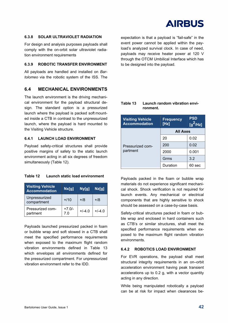
Bartolomeo User Guide, Issue 1 42
6.3.8 SOLAR ULTRAVIOLET RADIATION
For design and analysis purposes payloads shall
comply with the on-orbit solar ultraviolet radia-
tion environment requirements
6.3.9 ROBOTIC TRANSFER ENVIRONMENT
All payloads are handled and installed on Bar-
tolomeo via the robotic system of the ISS. The
expectation is that a payload is “fail-safe” in the
event power cannot be applied within the pay-
load’s analyzed survival clock. In case of need,
payloads may receive heater power at 120 V
through the OTCM Umbilical Interface which has
to be designed into the payload.
6.4 MECHANICAL ENVIRONMENTS
The launch environment is the driving mechani-
cal environment for the payload structural de-
sign. The standard option is a pressurized
launch where the payload is packed soft mount-
ed inside a CTB in contrast to the unpressurized
launch, where the payload is hard mounted to
the Visiting Vehicle structure.
6.4.1 LAUNCH LOAD ENVIRONMENT
Payload safety-critical structures shall provide
positive margins of safety to the static launch
environment acting in all six degrees of freedom
simultaneously (Table 12).
Table 12 Launch static load environment
Visiting Vehicle Accommodation
Nx[g] Ny[g] Nz[g]
Unpressurized compartment
+/10 +/8 +/8
Pressurized com-partment
+7.0/-7.0
+/-4.0 +/-4.0
Payloads launched pressurized packed in foam
or bubble wrap and soft stowed in a CTB shall
meet the specified performance requirements
when exposed to the maximum flight random
vibration environments defined in Table 13
which envelopes all environments defined for
the pressurized compartment. For unpressurized
vibration environment refer to the IDD.
Table 13 Launch random vibration envi-ronment.
Visiting Vehicle Accommodation
Frequency [Hz]
PSD
[g2/Hz]
Pressurized com-partment
All Axes
20 0.02
200 0.02
2000 0.001
Grms 3.2
Duration 60 sec
Payloads packed in the foam or bubble wrap
materials do not experience significant mechani-
cal shock. Shock verification is not required for
launch events. Any mechanical or electrical
components that are highly sensitive to shock
should be assessed on a case-by-case basis.
Safety-critical structures packed in foam or bub-
ble wrap and enclosed in hard containers such
as CTB’s or similar structures, shall meet the
specified performance requirements when ex-
posed to the maximum flight random vibration
environments.
6.4.2 ROBOTICS LOAD ENVIRONMENT
For EVR operations, the payload shall meet
structural integrity requirements in an on–orbit
acceleration environment having peak transient
accelerations up to 0.2 g, with a vector quantity
acting in any direction.
While being manipulated robotically a payload
can be at risk for impact when clearances be-
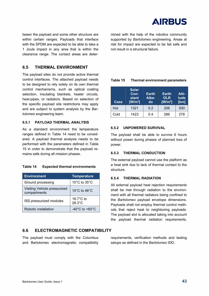
Bartolomeo User Guide, Issue 1 43
tween the payload and some other structure are
within certain ranges. Payloads that interface
with the SPDM are expected to be able to take a
1 Joule impact in any area that is within the
clearance range. The contact areas are deter-
mined with the help of the robotics community
supported by Bartolomeo engineering. Areas at
risk for impact are expected to be fail safe and
not result in a structural failure.
6.5 THERMAL ENVIRONMENT
The payload sites do not provide active thermal
control interfaces. The attached payload needs
to be designed to rely solely on its own thermal
control mechanisms, such as optical coating
selection, insulating blankets, heater circuits,
heat-pipes, or radiators. Based on selection of
the specific payload site restrictions may apply
and are subject to system analysis by the Bar-
tolomeo engineering team.
6.5.1 PAYLOAD THERMAL ANALYSIS
As a standard environment the temperature
ranges defined in Table 14 need to be consid-
ered. A payload thermal analysis needs to be
performed with the parameters defined in Table
15 in order to demonstrate that the payload re-
mains safe during all mission phases.
Table 14 Expected thermal environments
Environment Temperature
Ground processing 10°C to 35°C
Visiting Vehicle pressurized compartments
10°C to 46°C
ISS pressurized modules 16.7°C to 28.3°C
Robotic installation -40°C to +60°C
Table 15 Thermal environment parameters
Case
Solar Con-stant
[W/m²]
Earth Albe-
do
Earth OLR
[W/m²]
Alti-tude [km]
Hot 1321 0.2 206 500
Cold 1423 0.4 286 278
6.5.2 UNPOWERED SURVIVAL
The payload shall be able to survive 6 hours
without power during phases of planned loss of
power.
6.5.3 THERMAL CONDUCTION
The external payload cannot use the platform as
a heat sink due to lack of thermal contact to the
structure.
6.5.4 THERMAL RADIATION
All external payload heat rejection requirements
shall be met through radiation to the environ-
ment with all thermal radiators being confined to
the Bartolomeo payload envelope dimensions.
Payloads shall not employ thermal control meth-
ods that reject heat to neighboring payloads.
The payload slot is allocated taking into account
the payload thermal radiation requirements.
6.6 ELECTROMAGNETIC COMPATIBILITY
The payload must comply with the Columbus
and Bartolomeo electromagnetic compatibility
requirements, verification methods and testing
setups as defined in the Bartolomeo IDD.
Bartolomeo User Guide, Issue 1 44
7 SAFETY
Bartolomeo is part of the International Space
Station, all payload operations are required to be
compliant with the existing ISS Safety require-
ments which are designed to ensure ISS sys-
tem, crew and visiting vehicle safety.
The safety requirements and review processes
are well-defined and straight-forward. The Bar-
tolomeo technical team takes care of the pay-
load safety certification based on Customer pay-
load design and requirements verification. This
section on payload safety describes the bounda-
ry conditions under which the Customer needs
to design the payload.
7.1 HAZARD DEFINITION
Catastrophic hazards are defined as any condi-
tion which may result in either:
• A disabling or fatal personnel injury,
• Loss of the ISS,
• Loss of a crew-carrying vehicle
• Loss of a major ground facility
The payload shall be designed such that no
combination of two failures, two operator errors
(or one of each), can cause a disabling or fatal
personnel injury or loss of one of the following:
loss of ISS, loss of a crew-carrying vehicle, or
loss of major ground facility.
A critical hazard is any condition which may
result in either:
• A non-disabling personnel injury or illness
• Loss of a major ISS element
• Loss of robotic system use
The payload shall be designed such that no
single failure or single operator error can cause
a non-disabling personnel injury or illness, loss
of a major ISS element, loss of redundancy (i.e.
with only a single hazard control remaining) for
on-orbit life sustaining function, or loss of use of
the Space Station Remote Manipulator System
(SSRMS).
Typical hazards to be assessed for hazard po-
tential (critical or catastrophic):
• Structural failure
• Pressure System Failure, Leakage
• Propulsion system hazards
• Deployment of appendages
• Radio Frequency (RF) system operation
• Battery Failure
• Flammable or toxic material usage
• Frangible material usage
• Electrical system failures, and (EMI)
• Magnetic field
• Collision with ISS
• Sharp edges, pinch points, touch hazards
• Operational hazards
7.2 CONTROL OF HAZARDS
Control of hazards shall be appropriate for the
hazard type and occurrence.
Control of hazards have to be appropriate for the
hazard type and occurrence. Typical hazard
controls are summarized in Table 16.
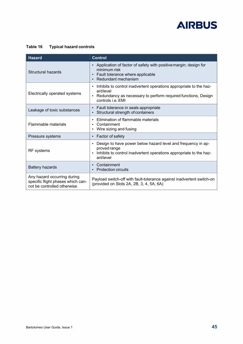
Bartolomeo User Guide, Issue 1 45
Table 16 Typical hazard controls
Hazard Control
Structural hazards
• Application of factor of safety with positive margin; design for minimum risk
• Fault tolerance where applicable • Redundant mechanism
Electrically operated systems
• Inhibits to control inadvertent operations appropriate to the haz-ard level
• Redundancy as necessary to perform required functions, Design controls i.e. EMI
Leakage of toxic substances • Fault tolerance in seals appropriate • Structural strength of containers
Flammable materials • Elimination of flammable materials • Containment • Wire sizing and fusing
Pressure systems • Factor of safety
RF systems
• Design to have power below hazard level and frequency in ap-proved range
• Inhibits to control inadvertent operations appropriate to the haz-ard level
Battery hazards • Containment • Protection circuits
Any hazard occurring during specific flight phases which can-not be controlled otherwise
Payload switch-off with fault-tolerance against inadvertent switch-on (provided on Slots 2A, 2B, 3, 4, 5A, 6A)
Bartolomeo User Guide, Issue 1 46
8 RISK SHARING WITH CUSTOMERS
8.1 CUSTOMER RESPONSIBILI-TIES
The following provides an overview of Bar-
tolomeo customers responsibilities, details are
defined via the IDD and contracts proceedings:
• The Customer agrees to furnish Airbus with
all necessary material and data required to
assure compliance with the Airbus and NASA
safety regulations.
• The launch and insertion of a payload on the
Bartolomeo platform may be subject to regu-
latory requirements. The Customer needs to
ensure compliance with any and all applica-
ble domestic and/or international regulations.
8.2 SERVICE CONDITIONS
Some or all aspects of the space flight program,
including the flight opportunity and the launch
date, the time on-board ISS, the insertion onto
the Bartolomeo platform, the ability of the crew
to interface with the payload, or the specific mis-
sion that will carry the payload may change in
date or duration, or become unable to be real-
ized. The following list identifies potential situa-
tions which may impact a payload deployment
but are outside the control of Airbus, detailed
agreements will be agreed upon in the service
contract:
• Cancelled flight opportunity.
• Launch failure resulting in the loss of the
Customer payload.
• Mission becomes unable to be realized due
to any change in policy, procedure or agree-
ment instituted by ESA or NASA or any or-
ganization
• Customer payload failure.
• NASA is the final arbitrator on all issues re-
lated to the flight opportunity including, but
not limited to, flight manifest, safety review,
and technical review, access to crew time,
deployment and return.
• Airbus and its commercial partners do not
retain any intellectual property rights from da-
ta, research or commercial products resulting
from Customer payload missions. The Cus-
tomer may protect his intellectual property by
appropriate technical means when it is within
the perimeter of the Bartolomeo All-in-one
Mission Service.
8.3 PRIORITY OF USE
Any schedule or milestone in the Customer con-
tract, is estimated based upon the parties’ cur-
rent understanding of the projected availability of
Airbus’s ISS allocations. The use of the ISS by
all parties is subject to and contingent upon the
availability of ESA and NASA goods, services,
facilities, or equipment. The Customer accepts
the risk that ESA or NASA priorities may impact
Customer’s priority and use of the ISS. User
further acknowledges that the availability of
these ESA or NASA resources may be outside
the authority and control of Airbus..
Bartolomeo User Guide, Issue 1 47
9 ITEMS TO BE DELIVERED BY THE CUSTOMER
9.1 MISSION INFORMATION FOR ISS PARTNERS
For general understanding of the payload mis-
sion objectives by the ISS Partners the following
payload mission information is required:
• Short summary of the activity in the targeted
Bartolomeo payload facility, including the re-
search scope and objectives. Brief descrip-
tion of the experimental setup.
• Brief description of the provided hardware
• General description of the expected scientific
deliverables (e.g. returned samples, sensor
data, housekeeping data, and experiment
timing data)
• Description of the end-to-end experiment
process including, duration, timeline
• Programmatic status, hardware development
status, target turnover date and desired on-
orbit performance window
9.2 INITIAL PAYLOAD SPECIFICA-TION
For the initial payload feasibility assessment, the
following data shall be provided by the Custom-
er:
• Preliminary payload property data: mass,
volume, dimensions (for up/download)
• Power consumption data (peak, average,
minimum)
• Battery type and toxicity code (if applicable)
• Emissions (type, quantity if applicable)
• Substances inside/hazardous materials?
(Type, quantity, and hazard response level),
release of (toxic) constituents etc.
• Conditioned stowage required? (during up-
load, on-orbit, download), including the fol-
lowing information: quantities (mass, volume,
dimensions), toxicity level, desired tempera-
ture, coldest/warmest temperature allowed,
loss of science temperature (warm-
est/coldest), total loss of science temperature
(warmest/coldest), post-landing optimal tem-
perature (min/max); specific packaging and
orientation requirements,
• Volume of real-time data or video
up/downlink required (estimate);
• Experiment duration; continuous, intermittent
• Margins in case of launch delays (including
rationale) – how long can the experi-
ment/samples survive without service in case
of delays?
• On-orbit operations (OPS) start constraints;
• Launch site preparation requirements (includ-
ing start date in L-days), and launch site la-
boratory requirements (e.g. consumables,
hardware);
• Payload orientation requirements;
• Disposal type (post-Ops);
• Other/unique payload constraints;
• Project schedule
9.3 CUSTOMER DELIVERABLE ITEMS IN SUPPORT OF PRO-JECT IMPLEMENTATION
All items to be provided by the Customer are
defined in the IDD and later baselined in a pay-
load specific Interface Control Agreement (ICA).
Depending on specific design and complexity
date delivery requirements start at about L – 18
months until the Certificate of Flight Readiness
around L- 4 months.
Bartolomeo User Guide, Issue 1 48
10 FREQUENTLY ASKED QUESTIONS
What happens if my payload fails to launch on schedule?
Answer: Airbus cannot control any changes in launch schedules, delays or cancellations for launches. If
your payload is impacted by these changes, Airbus will work to resolve the issue to ensure that your pay-
load gets to fly as close to originally scheduled as possible.
Can Airbus help with the “paperwork” of obtaining launch readiness?
Answer: Yes! Airbus can assist with every part of the process if requested by the client. These additions
will be built into the contract between the payload Customer and Airbus. Airbus can even help to develop
the payload if needed.
What if my payload fails to perform as planned during its time on orbit?
Answer: Airbus will work to ensure success to the best of their ability during time on orbit, although some
issues cannot be resolved while in orbit. Airbus will work with the client to make sure that they are setup
for success before, during and after flight.
How long will the entire process be from start to finish?
Answer: The length of the process is dependent on the amount of additional services requested by the
client. If the client comes with a ready-to-fly payload, it can take as little as 10 - 12 months before launch,
but depending on development status, it could typically take 24 months until turnover for launch. Airbus
works diligently to provide flexible timelines and launch opportunities to all its customers, depending on
complexity and readiness status.
What if the slot on Bartolomeo I wanted is already booked for launch?
Answer: There are many slots that share capabilities and viewing advantages, although they may go fast.
To best guarantee a slot that will fit your needs for launch, you may need to look at further out launch
dates or consider “ride sharing” with another Customer. Airbus will work with each Customer to make
sure that they each get the best outcome from their projects.
What is the difference between the different payload volumes described in this document?
Answer: First there is the maximum payload envelope which Bartolomeo can accommodate. This is given
by the total Bartolomeo volume available for payloads, minimum clearances, CoG requirements and
structural capabilities.
The NanoRacks airlock which is currently finalizing their design is planned to accommodate up to 4 Bar-
tolomeo payloads within one airlock cycle.
The smaller volume is determined by the JEM airlock JOTI adaptor, ref. section 3.6, which can accom-
modate only one smaller Bartolomeo payload at a time, however this size provides the greatest flexibility
because it can use either airlock based on first availability. Payloads using an airlock will be launched soft
stowed in the pressurized volume.

Bartolomeo User Guide, Issue 1 49