
BALLCENTRIC PLUG VALVE - Henry Pratt Company€¦ · valves (3" – 12"), fitting the tight...
24
BALLCENTRIC ® PLUG VALVE Engineering Creative Solutions for Fluid Systems Since 1901
Transcript of BALLCENTRIC PLUG VALVE - Henry Pratt Company€¦ · valves (3" – 12"), fitting the tight...
BALLCENTRIC® PLUG VALVEEngineering Creative Solutions for Fluid Systems Since 1901
TABLE OF CONTENTSBALLCENTRIC® PLUG VALVE
Scope of Line ............................................................................................................................................................................................................................................................. 1
Features and Benefits ............................................................................................................................................................................................................................................. 2
Dimensional Data ..................................................................................................................................................................................................................................................... 3
Standard Materials of Construction, Fig. 601 / 600, 12" & Smaller ................................................................................................................................................. 4
Standard Materials of Construction, Fig. 601 / 600, 14" & Larger ................................................................................................................................................... 5
Flanged End, Fig. 601 Cast Iron / 611 Ductile Iron 2 1/2" - 12" .......................................................................................................................................................... 6
Mechanical Joint, Fig. 600 Cast Iron / 620 Ductile Iron 3" - 12" ........................................................................................................................................................ 7
Flanged End Fig. 601 Cast Iron / 611 Ductile Iron and Mechanical Joint ...................................................................................................................................... 8
End, Fig. 600 Cast Iron / 620 Ductile Iron 14" & Larger ........................................................................................................................................................................ 8
Flanged End Fig. 602 Class 250 2 1/2" and Larger .................................................................................................................................................................................. 9
Flanged End Rubberlined 3" & Larger ..........................................................................................................................................................................................................10
Grooved End, Fig. 606 2 1/2" - 20" .................................................................................................................................................................................................................11
Adaption .....................................................................................................................................................................................................................................................................12
Technical Specification Series 601 / 600 Cast Iron Valves ..................................................................................................................................................................13
Technical Specification Series 602 Class 250 Valves .............................................................................................................................................................................14
Technical Specification Rubberlined Valves ...............................................................................................................................................................................................15
Technical Specification Series 601S Stainless Steel Valves ................................................................................................................................................................16
Technical Specification Series 611 Ductile Iron Valves ........................................................................................................................................................................17
Technical Specification Glass Lined Valves ................................................................................................................................................................................................18
1
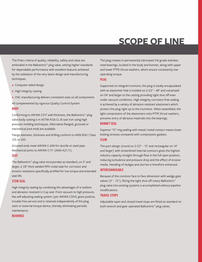
SCOPE OF LINE
The Pratt criteria of quality, reliability, safety and value are embodied in the Ballcentric® plug valve, setting higher standards for dependable performance with excellent features achieved by the utilization of the very latest design and manufacturing techniques.
• Computer aided design
• High integrity casting
• CNC manufacturing delivers consistent sizes on all components
All complemented by rigorous Quality Control System
BODY Conforming to AWWA C517 wall thickness, the Ballcentric® plug valve body casting is in ASTM A126 CL B cast iron using high pressure molding techniques. Alternative flanged, grooved or mechanical joint ends are available.
Flange diameter, thickness and drilling conform to ANSI B16.1 Class 125 or 250.
Grooved ends meet AWWA C-606 for ductile or steel pipe. Mechanical joints to AWWA C111 (ANSI A21.11).
SEAT The Ballcentric® plug valve incorporates as standard, on 3" and larger, a 1/8" thick welded 99% nickel seat for corrosion and erosion resistance specifically profiled for low torque and extended seat life.
STEM SEAL High integrity sealing by combining the advantages of a resilient and abrasion resistant U-Cup seal. From vacuum to high pressure, the self-adjusting sealing system (per AWWA C504) gives positive, trouble-free service and is retained independently of the plug stem or external torque device, thereby eliminating periodic maintenance.
BEARINGS
The plug rotates in permanently lubricated 316 grade stainless steel bearings, located in the body and bonnet, along with upper and lower PTFE thrust washers, which ensure consistently low operating torque.
PLUG Supported on integral trunnions, the plug is totally encapsulated with an elastomer that is molded on 2-1/2" – 48" and vulcanized on 54" and larger to the casting providing tight shut off even under vacuum conditions. High integrity corrosion-free sealing is achieved by a variety of abrasion resistant elastomers which protect the plug right up to the trunnions. When assembled, the light compression of the elastomers onto PTFE thrust washers, prevents entry of abrasive materials into the bearings.
BONNET SEAL Superior “O” ring sealing with metal / metal contact means lower bolting stresses compared with compression gaskets.
FLOW The port design (round on 2-1/2" – 12" and rectangular on 14" and larger) with streamlined internal contours gives the highest industry capacity straight through flow in the full open position, reducing turbulence and pressure drop and the effect of erosive media. Handling of sludges and slurries is therefore enhanced.
INTERCHANGEABLE Because of the common face to face dimension with wedge gate valves (3" – 12"), fitting the tight shut-off rotary Ballcentric® plug valve into existing systems is accomplished without pipeline modifications.
TRAVEL STOPS Adjustable open and closed travel stops are fitted as standard on both wrench and gear operated Ballcentric® plug valves.
2
INSTALLATIONThe Ballcentric® plug valve is suitable for flow and shut-off in either direction. Seat end downstream is the preferred orientation and any reverse flow requirement should be stated at the time of order. For use on fluids with suspended solids, it is recommended that the valve should be installed with the seat upstream and the valve stem horizontal with plug rotation to the top of the valve ensuring smooth operation.
IN-LINE MAINTENANCEIn the unlikely event of stem leakage, the stem seals can be easily replaced without removing the bonnet. Access to the body for cleaning or inspection does not require removal from the line.
MODULAR CONSTRUCTIONDesign of the bonnet and stem allows for on-site adaption of gear operators, power actuators, or extension devices on to standard valves. Conversion can be easily undertaken without removing the valve bonnet, thereby minimizing downtime.
POWER OPERATIONPneumatic, electric or hydraulic operation is available, complete with accessories such as limit switches, solenoid valves and positioners when required.
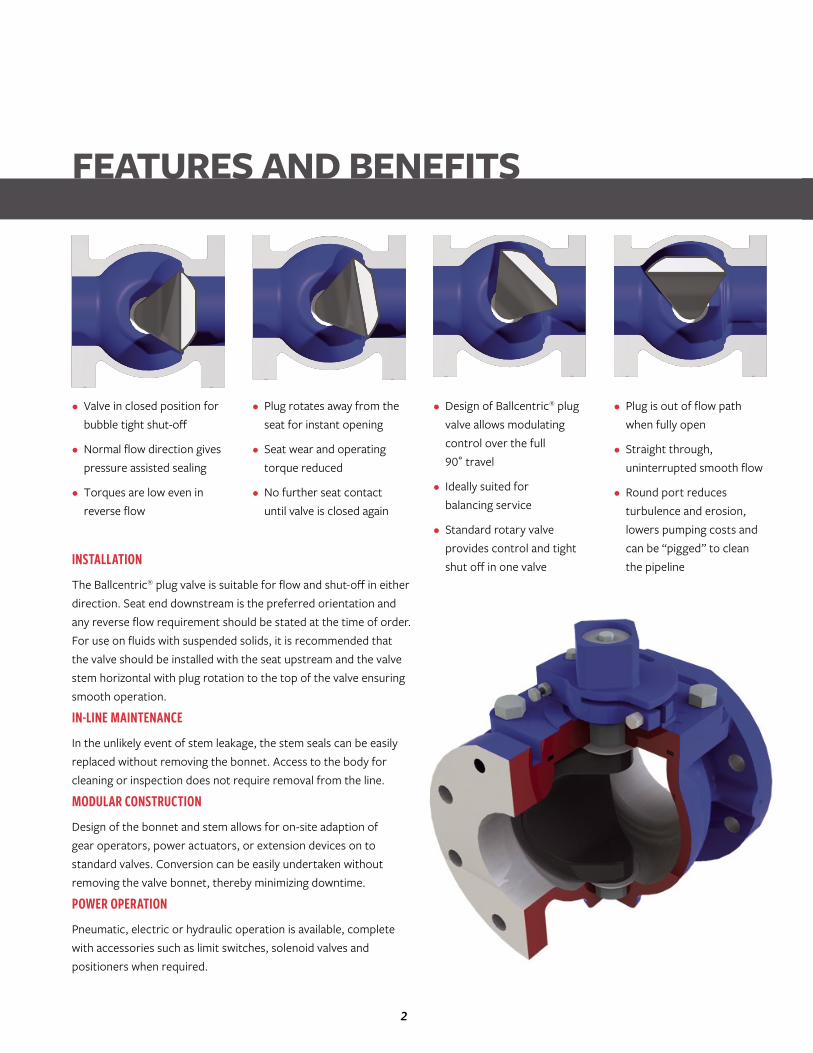
• Valve in closed position for bubble tight shut-off
• Normal flow direction gives pressure assisted sealing
• Torques are low even in reverse flow
• Plug rotates away from the seat for instant opening
• Seat wear and operating torque reduced
• No further seat contact until valve is closed again
• Design of Ballcentric® plug valve allows modulating control over the full 90˚ travel
• Ideally suited for balancing service
• Standard rotary valve provides control and tight shut off in one valve
• Plug is out of flow path when fully open
• Straight through, uninterrupted smooth flow
• Round port reduces turbulence and erosion, lowers pumping costs and can be “pigged” to clean the pipeline
FEATURES AND BENEFITS
3
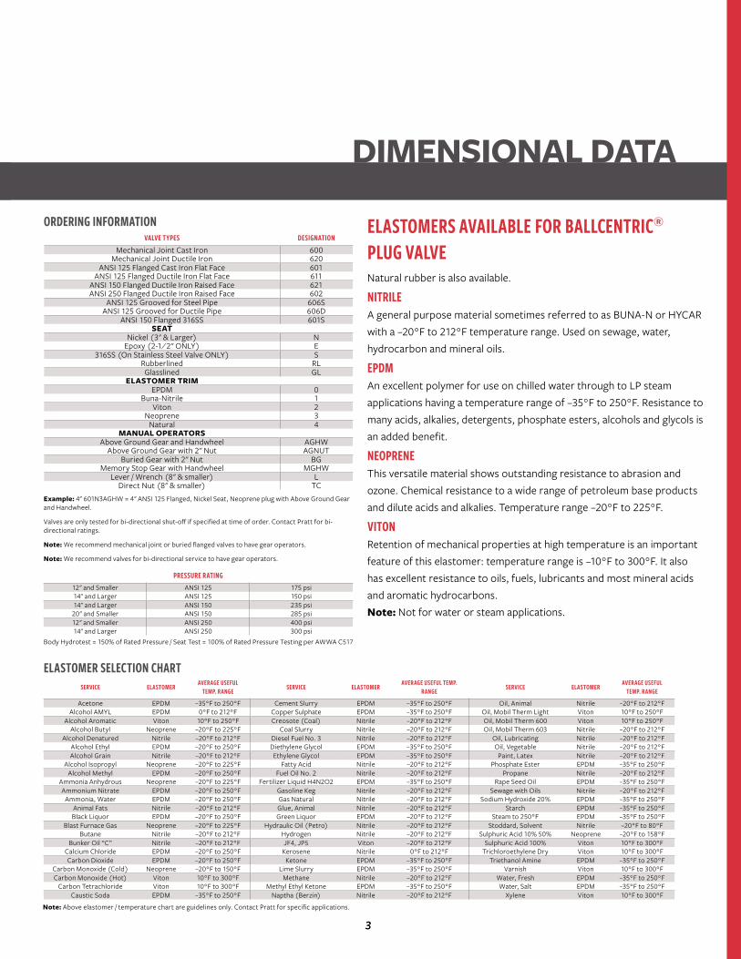
ELASTOMERS AVAILABLE FOR BALLCENTRIC® PLUG VALVENatural rubber is also available.
NITRILE A general purpose material sometimes referred to as BUNA-N or HYCAR with a –20°F to 212°F temperature range. Used on sewage, water, hydrocarbon and mineral oils.
EPDM An excellent polymer for use on chilled water through to LP steam applications having a temperature range of –35°F to 250°F. Resistance to many acids, alkalies, detergents, phosphate esters, alcohols and glycols is an added benefit.
NEOPRENE This versatile material shows outstanding resistance to abrasion and ozone. Chemical resistance to a wide range of petroleum base products and dilute acids and alkalies. Temperature range –20°F to 225°F.
VITON Retention of mechanical properties at high temperature is an important feature of this elastomer: temperature range is –10°F to 300°F. It also has excellent resistance to oils, fuels, lubricants and most mineral acids and aromatic hydrocarbons. Note: Not for water or steam applications.
ORDERING INFORMATION
Example: 4" 601N3AGHW = 4" ANSI 125 Flanged, Nickel Seat, Neoprene plug with Above Ground Gear and Handwheel.
Valves are only tested for bi-directional shut-off if specified at time of order. Contact Pratt for bi-directional ratings.
Note: We recommend mechanical joint or buried flanged valves to have gear operators.
Note: We recommend valves for bi-directional service to have gear operators.
Note: Above elastomer / temperature chart are guidelines only. Contact Pratt for specific applications.
ELASTOMER SELECTION CHART SERVICE ELASTOMER AVERAGE USEFUL
TEMP. RANGE SERVICE ELASTOMER AVERAGE USEFUL TEMP. RANGE SERVICE ELASTOMER AVERAGE USEFUL
TEMP. RANGE
Acetone EPDM –35°F to 250°F Cement Slurry EPDM –35°F to 250°F Oil, Animal Nitrile –20°F to 212°FAlcohol AMYL EPDM 0°F to 212°F Copper Sulphate EPDM –35°F to 250°F Oil, Mobil Therm Light Viton 10°F to 250°F
Alcohol Aromatic Viton 10°F to 250°F Creosote (Coal) Nitrile –20°F to 212°F Oil, Mobil Therm 600 Viton 10°F to 250°FAlcohol Butyl Neoprene –20°F to 225°F Coal Slurry Nitrile –20°F to 212°F Oil, Mobil Therm 603 Nitrile –20°F to 212°F
Alcohol Denatured Nitrile –20°F to 212°F Diesel Fuel No. 3 Nitrile –20°F to 212°F Oil, Lubricating Nitrile –20°F to 212°FAlcohol Ethyl EPDM –20°F to 250°F Diethylene Glycol EPDM –35°F to 250°F Oil, Vegetable Nitrile –20°F to 212°FAlcohol Grain Nitrile –20°F to 212°F Ethylene Glycol EPDM –35°F to 250°F Paint, Latex Nitrile –20°F to 212°F
Alcohol Isopropyl Neoprene –20°F to 225°F Fatty Acid Nitrile –20°F to 212°F Phosphate Ester EPDM –35°F to 250°FAlcohol Methyl EPDM –20°F to 250°F Fuel Oil No. 2 Nitrile –20°F to 212°F Propane Nitrile –20°F to 212°F
Ammonia Anhydrous Neoprene –20°F to 225°F Fertilizer Liquid H4N2O2 EPDM –35°F to 250°F Rape Seed Oil EPDM –35°F to 250°FAmmonium Nitrate EPDM –20°F to 250°F Gasoline Keg Nitrile –20°F to 212°F Sewage with Oils Nitrile –20°F to 212°F
Ammonia, Water EPDM –20°F to 250°F Gas Natural Nitrile –20°F to 212°F Sodium Hydroxide 20% EPDM –35°F to 250°FAnimal Fats Nitrile –20°F to 212°F Glue, Animal Nitrile –20°F to 212°F Starch EPDM –35°F to 250°FBlack Liquor EPDM –20°F to 250°F Green Liquor EPDM –20°F to 212°F Steam to 250°F EPDM –35°F to 250°F
Blast Furnace Gas Neoprene –20°F to 225°F Hydraulic Oil (Petro) Nitrile –20°F to 212°F Stoddard, Solvent Nitrile –20°F to 80°FButane Nitrile –20°F to 212°F Hydrogen Nitrile –20°F to 212°F Sulphuric Acid 10% 50% Neoprene –20°F to 158°F
Bunker Oil “C” Nitrile –20°F to 212°F JF4, JP5 Viton –20°F to 212°F Sulphuric Acid 100% Viton 10°F to 300°FCalcium Chloride EPDM –20°F to 250°F Kerosene Nitrile 0°F to 212°F Trichloroethylene Dry Viton 10°F to 300°FCarbon Dioxide EPDM –20°F to 250°F Ketone EPDM –35°F to 250°F Triethanol Amine EPDM –35°F to 250°F
Carbon Monoxide (Cold) Neoprene –20°F to 150°F Lime Slurry EPDM –35°F to 250°F Varnish Viton 10°F to 300°FCarbon Monoxide (Hot) Viton 10°F to 300°F Methane Nitrile –20°F to 212°F Water, Fresh EPDM –35°F to 250°F
Carbon Tetrachloride Viton 10°F to 300°F Methyl Ethyl Ketone EPDM –35°F to 250°F Water, Salt EPDM –35°F to 250°FCaustic Soda EPDM –35°F to 250°F Naptha (Berzin) Nitrile –20°F to 212°F Xylene Viton 10°F to 300°F
VALVE TYPES DESIGNATIONMechanical Joint Cast Iron 600
Mechanical Joint Ductile Iron 620ANSI 125 Flanged Cast Iron Flat Face 601
ANSI 125 Flanged Ductile Iron Flat Face 611ANSI 150 Flanged Ductile Iron Raised Face 621ANSI 250 Flanged Ductile Iron Raised Face 602
ANSI 125 Grooved for Steel Pipe 606SANSI 125 Grooved for Ductile Pipe 606D
ANSI 150 Flanged 316SS 601SSEAT
Nickel (3" & Larger) NEpoxy (2-1⁄2" ONLY) E
316SS (On Stainless Steel Valve ONLY) SRubberlined RLGlasslined GL
ELASTOMER TRIMEPDM 0
Buna-Nitrile 1Viton 2
Neoprene 3Natural 4
MANUAL OPERATORSAbove Ground Gear and Handwheel AGHW
Above Ground Gear with 2" Nut AGNUTBuried Gear with 2" Nut BG
Memory Stop Gear with Handwheel MGHWLever / Wrench (8" & smaller) L
Direct Nut (8" & smaller) TC
DIMENSIONAL DATA
PRESSURE RATING12" and Smaller ANSI 125 175 psi14" and Larger ANSI 125 150 psi14" and Larger ANSI 150 235 psi20" and Smaller ANSI 150 285 psi12" and Smaller ANSI 250 400 psi14" and Larger ANSI 250 300 psi
Body Hydrotest = 150% of Rated Pressure / Seat Test = 100% of Rated Pressure Testing per AWWA C517
4
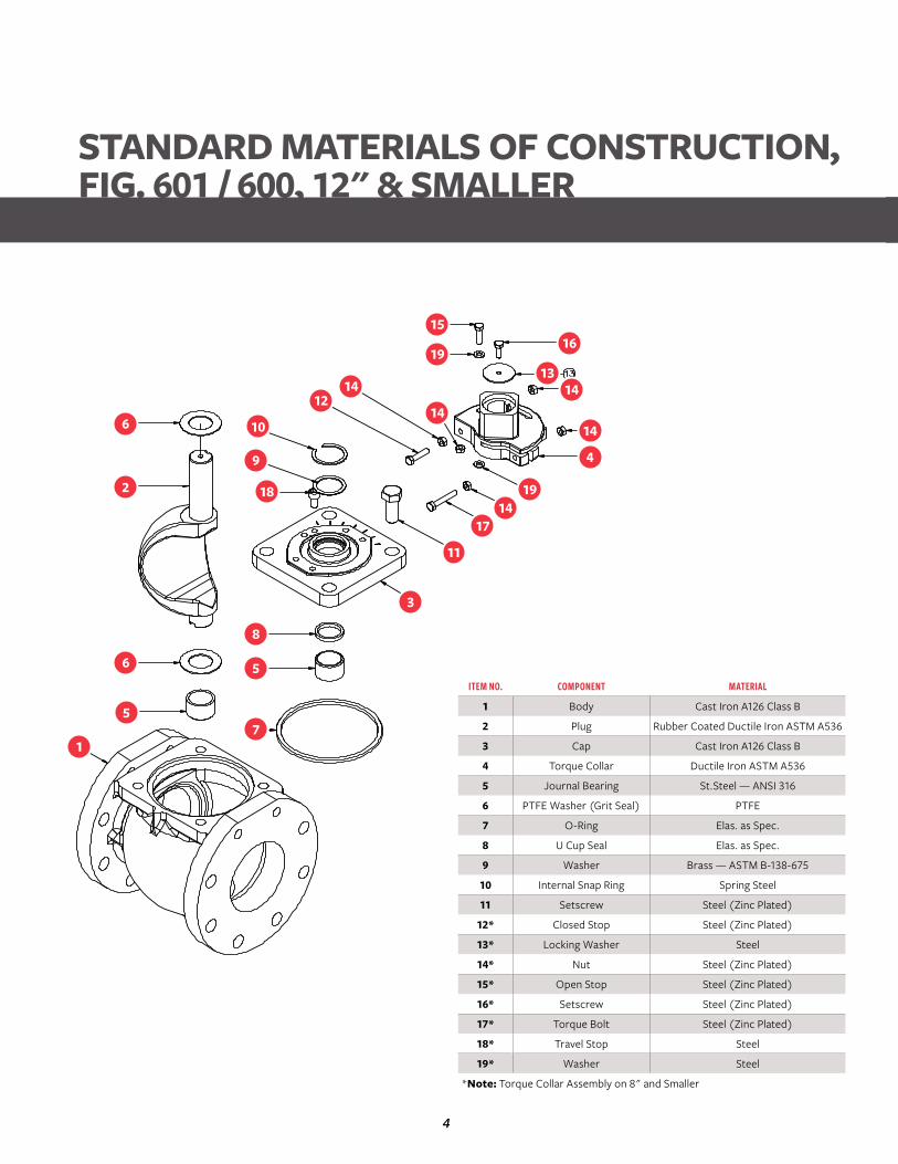
STANDARD MATERIALS OF CONSTRUCTION, FIG. 601 / 600, 12" & SMALLER
ITEM NO. COMPONENT MATERIAL
1 Body Cast Iron A126 Class B
2 Plug Rubber Coated Ductile Iron ASTM A536
3 Cap Cast Iron A126 Class B
4 Torque Collar Ductile Iron ASTM A536
5 Journal Bearing St.Steel — ANSI 316
6 PTFE Washer (Grit Seal) PTFE
7 O-Ring Elas. as Spec.
8 U Cup Seal Elas. as Spec.
9 Washer Brass — ASTM B-138-675
10 Internal Snap Ring Spring Steel
11 Setscrew Steel (Zinc Plated)
12* Closed Stop Steel (Zinc Plated)
13* Locking Washer Steel
14* Nut Steel (Zinc Plated)
15* Open Stop Steel (Zinc Plated)
16* Setscrew Steel (Zinc Plated)
17* Torque Bolt Steel (Zinc Plated)
18* Travel Stop Steel
19* Washer Steel
*Note: Torque Collar Assembly on 8" and Smaller
1
5
6
7
5
8
3
11
1714
19
4
14
1413
1619
14
1412
10
9
18
6
2
15
5
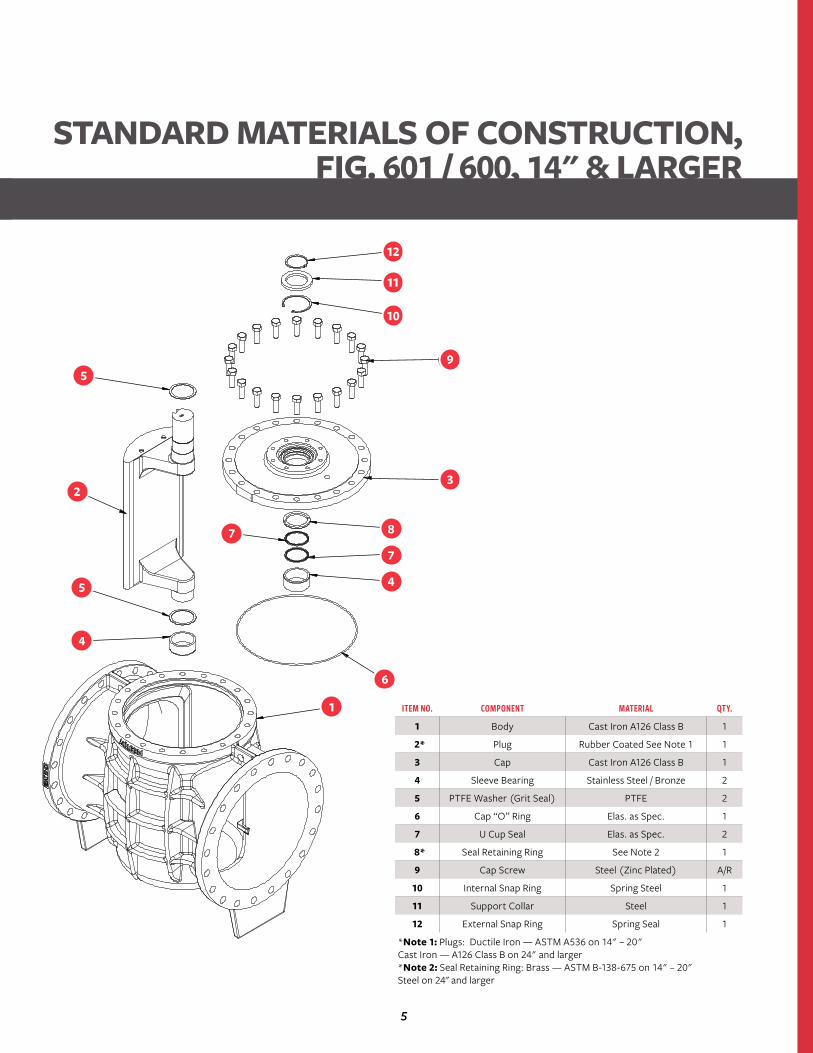
STANDARD MATERIALS OF CONSTRUCTION, FIG. 601 / 600, 14" & LARGER
ITEM NO. COMPONENT MATERIAL QTY.
1 Body Cast Iron A126 Class B 1
2* Plug Rubber Coated See Note 1 1
3 Cap Cast Iron A126 Class B 1
4 Sleeve Bearing Stainless Steel / Bronze 2
5 PTFE Washer (Grit Seal) PTFE 2
6 Cap “O” Ring Elas. as Spec. 1
7 U Cup Seal Elas. as Spec. 2
8* Seal Retaining Ring See Note 2 1
9 Cap Screw Steel (Zinc Plated) A/R
10 Internal Snap Ring Spring Steel 1
11 Support Collar Steel 1
12 External Snap Ring Spring Seal 1
*Note 1: Plugs: Ductile Iron — ASTM A536 on 14" – 20" Cast Iron — A126 Class B on 24" and larger*Note 2: Seal Retaining Ring: Brass — ASTM B-138-675 on 14" – 20" Steel on 24" and larger
1
6
4
7
8
3
9
10
11
12
7
5
2
5
4
6
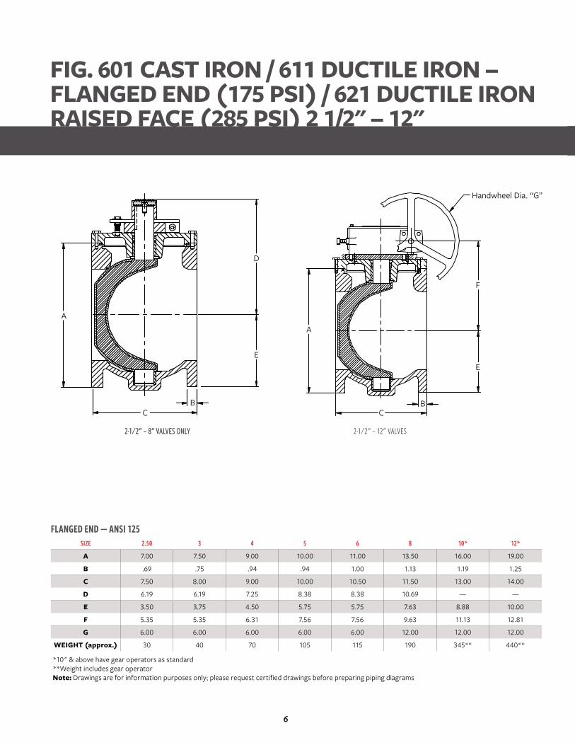
FLANGED END — ANSI 125SIZE 2.50 3 4 5 6 8 10* 12*
A 7.00 7.50 9.00 10.00 11.00 13.50 16.00 19.00
B .69 .75 .94 .94 1.00 1.13 1.19 1.25
C 7.50 8.00 9.00 10.00 10.50 11.50 13.00 14.00
D 6.19 6.19 7.25 8.38 8.38 10.69 — —
E 3.50 3.75 4.50 5.75 5.75 7.63 8.88 10.00
F 5.35 5.35 6.31 7.56 7.56 9.63 11.13 12.81
G 6.00 6.00 6.00 6.00 6.00 12.00 12.00 12.00
WEIGHT (approx.) 30 40 70 105 115 190 345** 440**
*10" & above have gear operators as standard**Weight includes gear operatorNote: Drawings are for information purposes only; please request certified drawings before preparing piping diagrams
2-1⁄2" – 8" VALVES ONLY
FIG. 601 CAST IRON / 611 DUCTILE IRON – FLANGED END (175 PSI) / 621 DUCTILE IRONRAISED FACE (285 PSI) 2 1/2" – 12"
2-1⁄2" – 8" VALVES ONLY 2-1⁄2" – 12" VALVES
A
CB
E
D
A
CB
E
F
Handwheel Dia. “G”
7
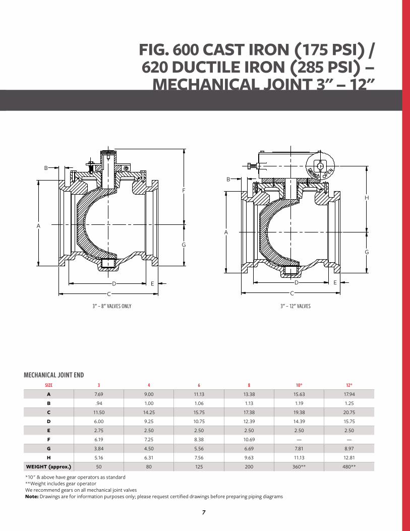
MECHANICAL JOINT ENDSIZE 3 4 6 8 10* 12*
A 7.69 9.00 11.13 13.38 15.63 17.94
B .94 1.00 1.06 1.13 1.19 1.25
C 11.50 14.25 15.75 17.38 19.38 20.75
D 6.00 9.25 10.75 12.39 14.39 15.75
E 2.75 2.50 2.50 2.50 2.50 2.50
F 6.19 7.25 8.38 10.69 — —
G 3.84 4.50 5.56 6.69 7.81 8.97
H 5.16 6.31 7.56 9.63 11.13 12.81
WEIGHT (approx.) 50 80 125 200 360** 480**
*10" & above have gear operators as standard**Weight includes gear operatorWe recommend gears on all mechanical joint valvesNote: Drawings are for information purposes only; please request certified drawings before preparing piping diagrams
3" – 8" VALVES ONLY 3" – 12" VALVES
FIG. 600 CAST IRON (175 PSI) / 620 DUCTILE IRON (285 PSI) –
MECHANICAL JOINT 3" – 12"
3" – 8" VALVES ONLY 3" – 12" VALVES
A
B
D
C
E
G
F
A
B
D
C
E
G
H
8
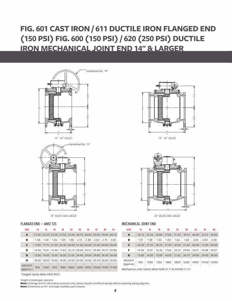
FLANGED END — ANSI 125SIZE 14 16 18 20 24 30 36 42 48 54
A 21.00 23.50 25.00 27.50 32.00 38.75 46.00 53.00 59.00 66.25
B 1.38 1.44 1.56 1.69 1.88 2.13 2.38 2.63 2.75 3.00
C 17.00 17.75 21.50 23.50 42.00 51.00 60.00 72.00 84.00 96.00
D 14.56 15.81 16.36 17.63 25.13 29.00 33.51 33.88 39.57 50.86
G 13.00 14.00 15.00 16.00 21.62 24.43 29.00 29.00 36.00 36.00
H 18.00 18.00 18.00 18.00 24.00 24.00 24.00 30.33 30.00 30.00
WEIGHT (approx.) 905 1030 1355 1880 3800 5200 6950 10160 13350 15100
Flanged Valves Meet ANSI B16.1
MECHANICAL JOINT ENDSIZE 14 16 18 20 24 30 36 42 48
A 20.13 22.56 24.84 27.06 31.50 39.13 46.00 53.13 60.00
B 1.31 1.38 1.43 1.50 1.62 1.68 2.00 2.00 2.00
C 24.50 27.25 29.25 31.00 42.00 51.00 60.00 72.00 84.00
F 14.56 15.81 16.36 17.63 25.13 29.00 33.51 33.88 39.57
G 13.00 14.00 15.00 16.00 21.62 24.75 29.00 29.00 36.00
WEIGHT (approx.) 905 1030 1355 1880 3800 5200 6950 10160 13350
Mechanical Joint Valves Meet ANSI 21.11 & AWWA C-111
14" –20" VALVES 14" –20" VALVES
24" VALVES AND LARGER 24" VALVES AND LARGER
Weight includes gear operatorNote: Drawings are for information purposes only; please request certified drawings before preparing piping diagrams.Note: Dimensions on 60" and larger available upon request.
FIG. 601 CAST IRON / 611 DUCTILE IRON FLANGED END (150 PSI) FIG. 600 (150 PSI) / 620 (250 PSI) DUCTILE IRON MECHANICAL JOINT END 14" & LARGER
Handwheel Dia. “H”
BC
A
D
G
Handwheel Dia. “H”
BC
G
D
A
C
G
B
F
C
A
G
B
F
A
9
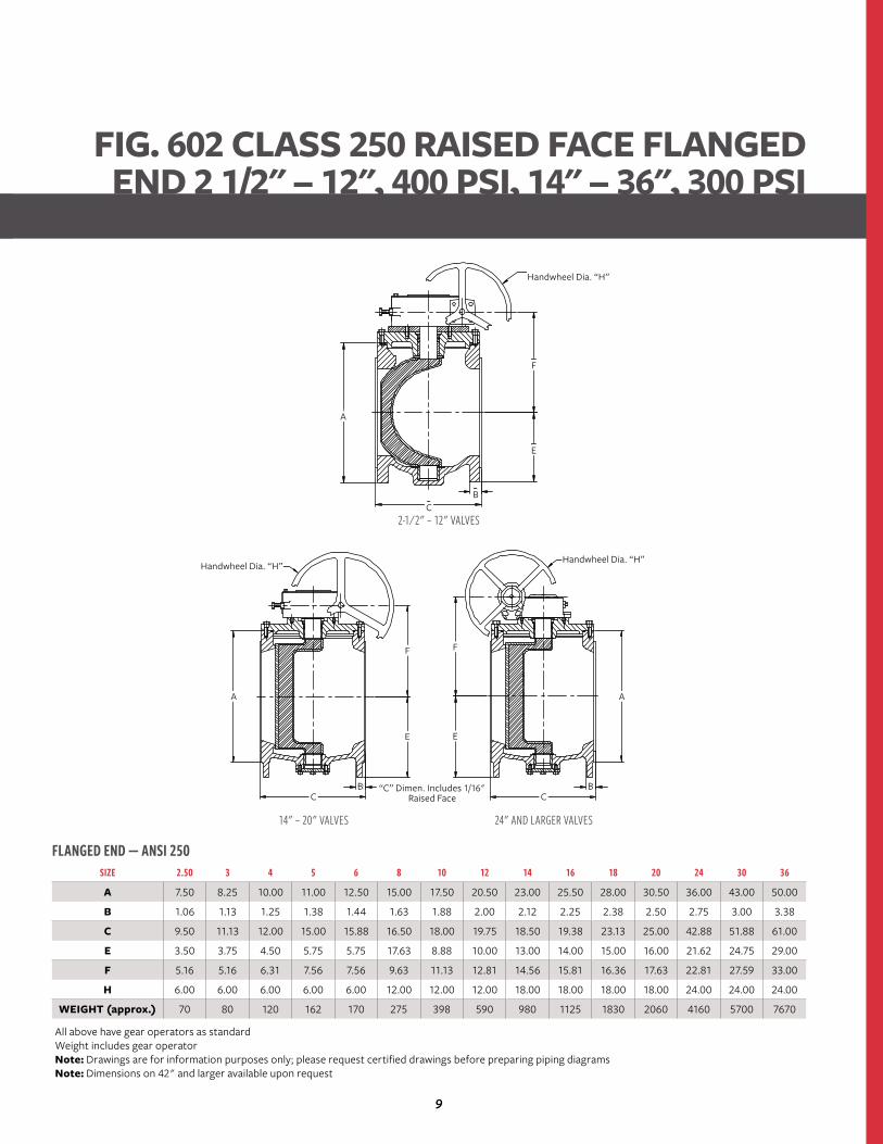
FLANGED END — ANSI 250SIZE 2.50 3 4 5 6 8 10 12 14 16 18 20 24 30 36
A 7.50 8.25 10.00 11.00 12.50 15.00 17.50 20.50 23.00 25.50 28.00 30.50 36.00 43.00 50.00
B 1.06 1.13 1.25 1.38 1.44 1.63 1.88 2.00 2.12 2.25 2.38 2.50 2.75 3.00 3.38
C 9.50 11.13 12.00 15.00 15.88 16.50 18.00 19.75 18.50 19.38 23.13 25.00 42.88 51.88 61.00
E 3.50 3.75 4.50 5.75 5.75 17.63 8.88 10.00 13.00 14.00 15.00 16.00 21.62 24.75 29.00
F 5.16 5.16 6.31 7.56 7.56 9.63 11.13 12.81 14.56 15.81 16.36 17.63 22.81 27.59 33.00
H 6.00 6.00 6.00 6.00 6.00 12.00 12.00 12.00 18.00 18.00 18.00 18.00 24.00 24.00 24.00
WEIGHT (approx.) 70 80 120 162 170 275 398 590 980 1125 1830 2060 4160 5700 7670
All above have gear operators as standardWeight includes gear operatorNote: Drawings are for information purposes only; please request certified drawings before preparing piping diagramsNote: Dimensions on 42" and larger available upon request
14" – 20" VALVES 24" AND LARGER VALVES
FIG. 602 CLASS 250 RAISED FACE FLANGED END 2 1/2" – 12", 400 PSI, 14" – 36", 300 PSI
2-1⁄2" – 12" VALVESC
F F
EE
A A
CCB B
B
E
F
A
Handwheel Dia. “H”
Handwheel Dia. “H”Handwheel Dia. “H”
“C” Dimen. Includes 1/16" Raised Face
10
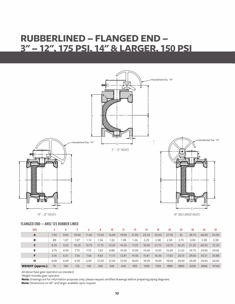
FLANGED END — ANSI 125 RUBBER LINEDSIZE 3 4 5 6 8 10 12 14 16 18 20 24 30 36 42
A 7.50 9.00 10.00 11.00 13.50 16.00 19.00 21.00 23.25 25.00 27.50 32 38.75 46.00 53.00
B .88 1.07 1.07 1.13 1.26 1.32 1.38 1.26 2.25 2.38 2.50 2.75 3.00 3.38 3.38
C 8.25 9.25 10.25 10.75 11.75 13.25 14.25 17.25 18.00 21.75 23.75 42.25 51.25 60.25 72.25
E 3.75 4.50 7.75 7.75 7.63 8.88 10.00 13.00 14.00 15.00 16.00 21.63 24.75 29.00 29.00
F 5.16 6.31 7.56 7.56 9.63 11.13 12.81 14.56 15.81 16.36 17.63 25.13 29.00 33.51 33.88
H 6.00 6.00 6.00 6.00 12.00 12.00 12.00 18.00 18.00 18.00 18.00 24.00 24.00 24.00 24.00
WEIGHT (approx.) 70 100 135 145 240 345 440 905 1030 1355 1880 3800 5200 6940 10160
All above have gear operators as standardWeight includes gear operatorNote: Drawings are for information purposes only; please request certified drawings before preparing piping diagramsNote: Dimensions on 48" and larger available upon request
3" – 12" VALVES
14" – 20" VALVES 24" AND LARGER VALVES
RUBBERLINED – FLANGED END – 3" – 12", 175 PSI, 14" & LARGER, 150 PSI
F
E
BC
A
Handwheel Dia. “H”
F
E
B
C
A
Handwheel Dia. “H”
F
E
BC
A
Handwheel Dia. “H”

11
GROOVED END — AWWA 606SIZE 2.50 3 4 5 6 8 10* 12* 14* 16* 18* 20*
A 2.50 3.00 4.00 5.00 6.00 8.00 10.00 12.00 14.00 15.25 16.19 18.06
C (Duct.) N/A 9.06 10.25 N/A 12.50 14.00 16.56 18.00 21.63 N/A 27.50 30.00
C (Steel) 7.13 8.50 10.13 12.38 12.38 13.88 16.44 17.88 21.63 22.50 27.50 30.00
D 6.19 6.19 7.25 8.38 8.38 10.69 — — — — — —
E 3.50 3.75 4.50 5.75 5.75 7.63 8.88 10.00 10.00 14.00 15.00 16.00
F 5.16 5.16 6.31 7.56 7.56 9.63 11.13 12.86 13.56 15.81 16.35 17.63
H 6.00 6.00 6.00 6.00 6.00 12.00 12.00 12.00 12.00 18.00 18.00 18.00
WEIGHT (approx.) 20 30 50 70 80 145 325** 420** RTF RTF RTF RTF
*10" & above have gear operators as standard**Weight includes gear operatorNote: Drawings are for information purposes only; please request certified drawings before preparing piping diagramsNote: Larger sizes are available. Contact Pratt Valve for data.
2-1⁄2" – 8" VALVES
2-1⁄2" – 12" VALVES 14" – 20" VALVES
FIG. 606 GROOVED END – 2 1/2" – 12", 175 PSI, 14" – 20", 150 PSI
F
E
C (Ductile)C (Steel)
øA
Handwheel Dia. “H”
F
E
C (Ductile)C (Steel)
øA
Handwheel Dia. “H”
D
E
C (Ductile)C (Steel)
øA
12
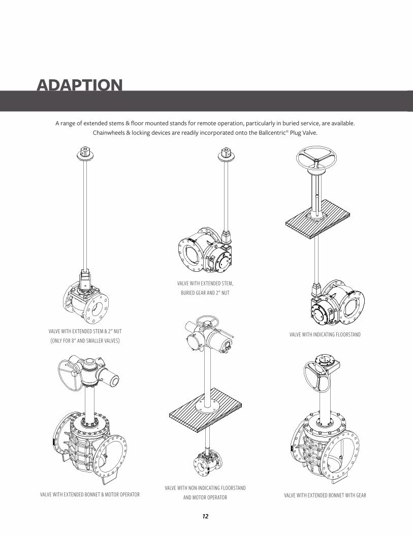
ADAPTION
VALVE WITH EXTENDED STEM & 2" NUT(ONLY FOR 8" AND SMALLER VALVES)
A range of extended stems & floor mounted stands for remote operation, particularly in buried service, are available. Chainwheels & locking devices are readily incorporated onto the Ballcentric® Plug Valve.
VALVE WITH EXTENDED BONNET & MOTOR OPERATOR
VALVE WITH EXTENDED STEM,BURIED GEAR AND 2" NUT
VALVE WITH NON-INDICATING FLOORSTAND AND MOTOR OPERATOR
VALVE WITH INDICATING FLOORSTAND
VALVE WITH EXTENDED BONNET WITH GEAR
13
TECHNICAL SPECIFICATIONBallcentric® Series 601 / 600 Plug Valves
AWWA C-517 STANDARDSValves shall be of the non-lubricated eccentric type with an elastomer covering all seating surfaces. The elastomer shall be suitable for the service intended. Flanged valves shall be manufactured in accordance with ANSI B16.1 Class 125 / 150 including facing, drilling and flange thickness. Mechanical joint ends shall be in compliance with AWWA / ANSI C-111. Grooved ends shall be manufactured to the dimensions of ANSI / AWWA C606 for ductile or steel pipe as required. Ports shall be round on sizes 2-1/2"-12" and rectangular port design on valves 14" and larger. All valves shall be capable of being “pigged” with a soft pig when required.
Valve bodies shall be of ASTM A-126 Class B cast iron and thickness in accordance with AWWA C-517 Section 4.4.1.4. Valves 3" and larger shall be furnished with a welded-in overlay seat of 1⁄8" thick of not less than 99% nickel in accordance with AWWA C-517, Section 4.3.3.4. Sprayed, plated or screwed-in seats are not acceptable.
Plugs shall be of ASTM A-536-Grade 65-45-12 for all sizes in compliance with AWWA C-517 Section 4.3.3.2. The plugs shall be of one piece solid construction with PTFE thrust bearings on the upper and lower bearing journals to reduce torque and prevent dirt and grit from entering the bearing and seal area.
Valves shall be furnished with replaceable sleeve type bearings conforming to AWWA C-517, Section 4.3.3.6. Bearings shall be
of sintered, oil impregnated type stainless steel. Valve shaft seals shall be of the “U” cup type in accordance with AWWA C-517 Section 4.4.7. Seals shall be self adjusting and repackable without removing the bonnet from the valve.
Wrench operated valves 2-1/2"-8" shall be capable of being converted to worm gear or automated operation without removing the bonnet or plug from the valve. All wrench operated valves shall be equipped with a 2" square nut for use with removeable levers or extended “T” handles.
Worm gear operators, where required, shall be of the heavy duty construction with the ductile iron quadrant supported on the top and bottom by oil impregnated bronze bearings. The worm gear and shaft shall be manufactured of hardened steel and run on high efficiency roller bearings.
Valves shall be designed and manufactured to shut off bubble tight at 175 psi for valves 2-1/2"-12" and 150 psi for valves 14" and larger. Each valve shall be given a hydrostatic and seat test with the test results being certified when required by the customer. Certified copies of Proof-of-Design test reports shall be furnished as outlined in AWWA C-517 Section 5.2.2 when requested.
Plug valves shall be Ballcentric® Plug Valve Series 601 / 600 as manufactured by Pratt.
14
TECHNICAL SPECIFICATIONBallcentric® Series 602 ANSI Class 250 Raised Face Plug Valves
AWWA C-517 STANDARDSValves shall be of the non-lubricated eccentric type with an elastomer covering all seating surfaces. The elastomer shall be suitable for the service intended. Flanged valves shall be manufactured in accordance with ANSI B16.1 Class 250 including facing, drilling and flange thickness. Ports shall be round on sizes 2-1/2" through 12" to facilitate “pigging” when required. Valves 14" and larger shall be of a rectangular port design.
Valve bodies shall be of ASTM A-536 Grade 65-45-12 ductile iron and thickness in accordance with AWWA C-517 Section 4.4.1.4. Valves 3" and larger shall be furnished with a welded-in overlay seat of 1/8" thick of not less than 99% nickel in accordance with AWWA C-517 Section 4.3.3.4. Sprayed, plated or screwed-in seats are not acceptable.
Plugs shall be of ASTM A-536-Grade 65-45-12 in compliance with AWWA C-517 Section 4.3.3.2. The plugs shall be of one piece solid construction with PTFE thrust bearings on the upper and lower bearing journals to reduce torque and prevent dirt and grit form entering the bearing and seal area.
Valves shall be furnished with replaceable sleeve type bearings conforming to AWWA C-517 Section 4.3.3.6. Bearings shall be of sintered, oil impregnated type stainless steel. Valve shaft seals shall be of the “U” cup type in accordance with AWWA C-517 Section 4.4.7. Seals shall be self adjusting and repackable without removing the bonnet from the valve.
Worm gear operators shall be of the heavy duty construction with the ductile iron quadrant supported on the top and bottom by oil impregnated bronze bearings. The worm gear and shaft shall be manufactured of hardened steel and run on high efficiency roller bearings. All worm gear operators shall be sized for bi-directional shutoff at the valves design pressure rating.
Valves shall be designed and manufactured to shut off bubble tight at 400 psi for valves 2-1/2"-12" and 300 psi for valves 14"-36" with pressure behind the plug.
Each valve shall be given a hydrostatic and seat test with the test results being certified when required by the customer. Certified copies of Proof-of-Design test reports shall be furnished as outlined in AWWA C-517 Section 5.2.2 when requested.
Plug valves shall be Ballcentric® Plug Valve Series 602 as manufactured by Pratt.
15
TECHNICAL SPECIFICATIONBallcentric® Rubberlined Plug Valves
AWWA C-517 STANDARDSValves shall be of the non-lubricated eccentric type with an elastomer covering all seating surfaces. The elastomer shall be suitable for the service intended. Flanged valves shall be manufactured in accordance with ANSI B16.1 Class 125 / 150 including facing, drilling and flange thickness. Mechanical joint ends shall be in compliance with AWWA / ANSI C-111- 92. Grooved ends shall be manufactured to the dimensions of ANSI / AWWA C606 for ductile or steel pipe as required. Ports shall be round on sizes 2-1/2"-12" and rectangular port design on valves 14" and larger. All valves shall be capable of being “pigged” with a soft pig when required.
Valve bodies shall be of ASTM A-126 Class B cast iron and thickness in accordance with AWWA C-517 Section 4.4.1.4. The interior of the valve bodies shall be covered with a suitable elastomer with a minimum thickness of 1/8". The elastomer shall extend through the valve flow way and onto the flanges to ensure a positive seal.
Plugs shall be of ASTM A-536-Grade 65-45-12 for all sizes in compliance with AWWA C-517 Section 4.3.3.2. The plugs shall be of one piece solid construction with PTFE thrust bearings on the
upper and lower bearing journals to reduce torque and prevent dirt and grit from entering the bearing and seal area.
Valves shall be furnished with replaceable sleeve type bearings conforming to AWWA C-517, Section 4.3.3.6. Bearings shall be of sintered, oil impregnated type stainless steel. Valve shaft seals shall be of the “U” cup type in accordance with AWWA C-517 Section 4.4.7. Seals shall be self adjusting and repackable without removing the bonnet from the valve.
Worm gear operators shall be of the heavy duty construction with the ductile iron quadrant supported on the top and bottom by oil impregnated bronze bearings. The worm gear and shaft shall be manufactured of hardened steel and run on high efficiency roller bearings. All worm gear operators shall be sized for bi-directional shutoff at the valves design pressure rating.
Valves shall be designed and manufactured to shut off bubble tight at 175 psi for valves 2-1/2"-12" and 150 psi for valves 14" and larger. Each valve shall be given a hydrostatic and seat test with the test results being certified when required by the customer. Certified copies of Proof-of-Design test reports shall be furnished as outlined in AWWA C-517 Section 5.2.2 when requested.
Plug valves shall be Ballcentric® Plug Valve as manufactured by Pratt.
16
AWWA C-517 STANDARDS Valves shall be of the non-lubricated eccentric type with an elastomer covering all seating surfaces. The elastomer shall be suitable for the service intended. Flanged valves shall be manufactured in accordance with ANSI B16.1 Class 125 including facing, drilling and flange thickness. Ports shall be round on sizes 2-1/2"-12" and rectangular port design on valves 14" and larger. All valves shall be capable of being “pigged” with a soft pig when required.
Valve bodies shall be of CF8M (316 stainless steel). Valves shall be furnished with 316 stainless steel seat in accordance with AWWA C-517 Section 4.3.3.4.
Plugs shall be of CF8M (316 stainless steel). The plugs shall be of one piece solid construction with PTFE thrust bearings on the upper and lower bearing journals to reduce torque and prevent dirt and grit from entering the bearing and seal area.
Valves shall be furnished with replaceable sleeve type bearings conforming to AWWA C-517 Section 4.3.3.6. Bearings shall be of sintered, oil impregnated type stainless steel. Valve shaft seals shall be of the “U” cup type in accordance with AWWA C-517 Section 4.4.7. Seals shall be self adjusting and repackable without removing the bonnet from the valve.
Wrench operated valves 2-1/2"-8" shall be capable of being converted to worm gear or automated operation without removing the bonnet or plug from the valve. All wrench operated valves shall be equipped with a 2" square nut for use with removable levers or extended “T” handles.
Worm gear operators, where required, shall be of the heavy duty construction with the ductile iron quadrant supported on the top and bottom by oil impregnated bronze bearings. The worm gear and shaft shall be manufactured of hardened steel and run on high efficiency roller bearings. All worm gear operators shall be sized for bi-directional shutoff at the valves design pressure rating.
Valves shall be designed and manufactured to shut off bubble tight at 275 psi. Each valve shall be given a hydrostatic and seat test with the test results being certified when required by the customer. Certified copies of Proof-of-Design test reports shall be furnished as outlined in AWWA C-517 Section 5.2.2 when requested.
Plug valves shall be Ballcentric® Plug Valve Series 601S as manufactured by Pratt.
TECHNICAL SPECIFICATIONBallcentric® Series 601S – Stainless Steel Plug Valves
17
AWWA C-517 STANDARDSValves shall be of the non-lubricated eccentric type with an elastomer covering all seating surfaces. The elastomer shall be suitable for the service intended. Flanged valves shall be manufactured in accordance with ANSI B16.1 Class 125 / 150 including facing, drilling and flange thickness. Mechanical joint ends shall be in compliance with AWWA / ANSI C-111-92. Grooved ends shall be manufactured to the dimensions of ANSI / AWWA C606 for ductile or steel pipe as required. Ports shall be round on sizes 2-1/2"-12" and rectangular port design on valves 14" and larger. All valves shall be capable of being “pigged” with a soft pig when required.
Valve bodies shall be of ASTM A-536 Grade 65-45-12 and thickness in accordance with AWWA C-517 Section 4.4.1.4. Valves 3" and larger shall be furnished with a welded-in overlay seat of 1/8" thick of not less than 99% nickel in accordance with AWWA C-517, Section 4.3.3.4. Sprayed, plated or screwed-in seats are not acceptable.
Plugs shall be of ASTM A-536-Grade 65-45-12 for all sizes in accordance with AWWA C-517 Section 4.3.3.2. The plugs shall be of one piece solid construction with PTFE thrust bearings on the upper and lower bearing journals to reduce torque and prevent dirt and grit from entering the bearing and seal area.
Valves shall be furnished with replaceable sleeve type bearings conforming to AWWA C-517, Section 4.3.3.6. Bearings shall be of sintered, oil impregnated type stainless steel. Valve shaft seals shall be of the “U” cup type in accordance with AWWA C-517 Section 4.4.7. Seals shall be self adjusting and repackable without removing the bonnet from the valve.
Wrench operated valves 2-1/2"-8" shall be capable of being converted to worm gear or automated operation without removing the bonnet or plug from the valve. All wrench operated valves shall be equipped with a 2" square nut for use with removeable levers or extended “T” handles.
Worm gear operators, where required, shall be of the heavy duty construction with the ductile iron quadrant supported on the top and bottom by oil impregnated bronze bearings. The worm gear and shaft shall be manufactured of hardened steel and run on high efficiency roller bearings. All worm gear operators shall be sized for bidirectional shutoff at the valves design pressure rating.
Valves shall be designed and manufactured to shut off bubble tight at 175 psi for valves 2-1/2"-12" and 150 psi for valves 14" and larger. Each valve shall be given a hydrostatic and seat test with the test results being certified when required by the customer. Certified copies of Proof-of-Design test reports shall be furnished as outlined in AWWA C-517 Section 5.2.2 when requested.
Plug valves shall be Ballcentric® Plug Valve Series 611 as manufactured by Pratt.
TECHNICAL SPECIFICATIONBallcentric® Series 611 – Ductile Iron Plug Valves
18
AWWA C517-09 STANDARDS Valves shall be of the non-lubricated eccentric type with an elastomer covering all seating surfaces. The elastomer shall be suitable for the service intended. Flanged valves shall be manufactured in accordance with ANSI B16.1 Class 125 / 150 including facing, drilling and flange thickness. Mechanical joint ends shall be in compliance with AWWA / ANSI C-111-92. Grooved ends shall be manufactured to the dimensions of ANSI / AWWA C606 for ductile or steel pipe as required. Ports shall be round on sizes 3"-12" and rectangular port design on valves 14" and larger. All valves shall be capable of being “pigged” with a soft pig when required.
Valve bodies shall be of ASTM A-126 Class B cast iron and thickness in accordance with AWWA C-517 Section 4.4.1.4. Interior of valves shall be glass lined at .008-.012 mils thickness, covering the entire interior of valve bodies and stopping at the flange faces.
Plugs shall be of ASTM A-536-Grade 65-45-12 for all sizes in compliance with AWWA C-517 Section 4.3.3.2. The plugs shall be of one piece solid construction with PTFE thrust bearings on the upper and lower bearing journals to reduce torque and prevent dirt and grit from entering the bearing and seal area.
Valves shall be furnished with replaceable sleeve type bearings conforming to AWWA C-517, Section 4.3.3.6. Bearings shall be
of sintered, oil impregnated type stainless steel. Valve shaft seals shall be of the “U” cup type in accordance with AWWA C-517 Section 4.4.7. Seals shall be self adjusting and repackable without removing the bonnet from the valve.
Wrench operated valves 2-1/2"-8" shall be capable of being converted to worm gear or automated operation without removing the bonnet or plug from the valve. All wrench operated valves shall be equipped with a 2" square nut for use with removeable levers or extended “T” handles.
Worm gear operators, where required, shall be of the heavy duty construction with the ductile iron quadrant supported on the top and bottom by oil impregnated bronze bearings. The worm gear and shaft shall be manufactured of hardened steel and run on high efficiency roller bearings. All worm gear operators shall be sized for bi-directional shutoff at the valves design pressure rating.
Valves shall be designed and manufactured to shut off bubble tight at 175 psi for valves 2-1/2"-12" and 150 psi for valves 14" and larger. Each valve shall be given a hydrostatic and seat test with the test results being certified when required by the customer. Certified copies of Proof-of-Design test reports shall be furnished as outlined in AWWA C-517 Section 5.2.2 when requested.
Plug valves shall be Ballcentric® Plug Valve Series as manufactured by Pratt.
TECHNICAL SPECIFICATIONBallcentric® Glass Lined Plug Valves

19
NOTES

20
NOTES

21
NOTES
Mueller refers to one or more of Mueller Water Products, Inc., a Delaware corporation (“MWP”), and its subsidiaries. MWP and each of subsidiaries are legally separate and independent entities when providing products and services. MWP does not provide products or services to third parties. MWP and each of its subsidiaries are liable only for their own acts and omissions and not those of each other. MWP brands include Mueller®, Echologics®, Hydro Gate®, Hydro-Guard®, Jones®, Mi.Net®, Milliken®, Pratt®, Singer®, and U.S. Pipe Valve & Hydrant. Please see www.muellerwp.com/about to learn more.
Copyright © 2018 Henry Pratt Company, LLC. All Rights Reserved. The trademarks, logos and service marks displayed in this document are the property of Mueller Water Products, Inc., its affiliates or other third parties. Products above marked with a section symbol (§) are subject to patents or patent applications. For details, visit www.prattvalve.com. These products are intended for use in potable water applications. Please contact your Mueller Sales or Customer Service Representative concerning any other application(s).
For more information about Pratt or to view our full line of water products, please visit www.prattvalve.com or call Pratt customer service at 1.800.423.1323.
401 S. Highland Ave., Aurora, IL 60506, [email protected], P: 1.800.423.1323
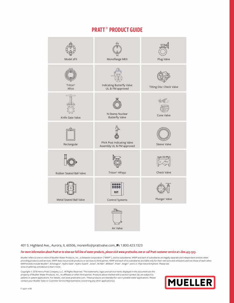
Model 2FII Monoflange MKII Plug Valve
Triton® XR70
Indicating Butterfly ValveUL & FM approved Tilting Disc Check Valve
Knife Gate ValveN-Stamp Nuclear
Butterfly ValveCone Valve
Rectangular PIVA Post Indicating Valve Assembly UL & FM approved Sleeve Valve
Rubber Seated Ball Valve Triton® HP250 Check Valve
Metal Seated Ball Valve Control Systems Plunger Valve
Air Valve
PRATT® PRODUCT GUIDE
F 13271 11/18