
BALL TANKS - frpmfg.com · LIMITED WARRANTY Manufacturer’s Warranty applies only to products...
13
PO Box 220, Asquith SK S0K 0J0 PH: (306) 329-4884 Toll Free: (866) 722-6246 FAX: (306) 329-4886 Email: [email protected] Website: www.frpmfg.com BALL TANKS Underground Installation Instructions Anchor Kit Assembly and Warranty Information
Transcript of BALL TANKS - frpmfg.com · LIMITED WARRANTY Manufacturer’s Warranty applies only to products...
PO Box 220, Asquith SK S0K 0J0
PH: (306) 329-4884 Toll Free: (866) 722-6246 FAX: (306) 329-4886
Email: [email protected] Website: www.frpmfg.com
BALL TANKS
Underground Installation Instructions
Anchor Kit Assembly and Warranty Information

TABLE OF CONTENTS 1. Limited Warranty ………………………………………………………………………..….. 3
2. Warranty Registration Form…………………………………………………………………4
2. Introduction ………………………………………………………………………………..….5
Owner Responsibilities
3. General ………………………………………………………………………………………… 5
4. Handling …………………………………………………………………………………….. 5-6
Tank Inspection
Unloading of Tank
Storing Tank
5. Excavation Parameters
……………………………….……………………………….……………….................. 6-7
Stable Soil Conditions
Unstable Soil Conditions
6. Placing Tank in Hole………………………………………………………….……………... 7
7. Bed and Backfill Material ………………………………………………………………….... 7
Approved Backfill Material
8. Cover …………………………….…………………………………………............................ 7
9. Installation - Dry Hole
………………………………………….…………………....................……………….. 9-10
10. Installation – Wet Hole
………….…………………………………………………………………………..……. 10-11
11. Installation – Freezing Weather
……………………………………………………………………….……………………... 11
12. Anchoring ………………………………………………………………….…………….. 11-13
General
Use of Deadmen
Use of Anchor Pad
Hold Downs
Tie-Down Kit Content

LIMITED WARRANTY
Manufacturer’s Warranty applies only to products manufactured by FRP Manufacturing
FRP Manufacturing (2010) Inc (FRP) fibreglass tanks are warranted against defects in material
and workmanship and will perform according to our specifications provided that assembly and
installation has proved satisfactory to FRP or agents.
Should any part (or parts) prove defective within five (5) years from the date of purchase, (proof
of purchase required) it will be replaced or repaired by FRP without charge. Permission must be
obtained from the factory prior to any warranty work being done.
Transportation to and from a dealer or factory will be at the owner’s expense.
No allowance will be made for labour or other charges in replacement of defective parts.
Consequential damages, if any, are specifically excluded from this warranty.
What is not covered?
This warranty does not cover:
1. A product which has been repaired or altered without written authorization from the
manufacturer or authorized Dealer or Distributor as to affect its use or operation.
2. Equipment or accessories, which are not manufactured by FRP, whether or not warranted
by other manufacturers.
3. Leakage from customer tanks that have been improperly assembled or improperly installed.
4. Product that has been abused, mishandled, accidentally damaged or operated contrary to
printed instructions provided.
5. Loss of time, inconvenience, travel expense or other matters not covered hereunder.
6. Excavation, landscaping, or other installation/removal costs.
7. Products not paid in full per terms of sale.
8. Any act of God.
No oral or written information or advice given by Dealers, representatives, agents, or employees
shall create a warranty or in any way increase the scope of this warranty. The manufacturer does
not authorize any person to extend the time of this warranty or to create or assume for it any
other obligation or liability with respect to its products. No person, including Dealers and
Distributors is authorized to make repairs or replacements under this warranty without the prior
written approval from the Manufacturer. This warranty in not transferable or assignable.
THE MANUFACTURER SHALL NOT BE LIABLE FOR CONSEQUENTIAL, SPECIAL OR
INCIDENTAL DAMAGE RESULTING FROM A BREACH OF THE EXPRESSED OR IMPLIED
WARRANTY WHICH IS NOT DISCLAIMED HEREIN NOR ANY OTHER LOSS OR DAMAGE,
EXCEPT AS SET FORTH ABOVE.
CONTACT INFORMATION FOR ANY WARRANTY INQUIRIES:
PHONE: (866) 722-6246 or (306) 329-4884
FAX: (306) 329-4886
EMAIL: [email protected]

WARRANTY REGISTRATION FORM This form must be completed at the time of installation and returned to FRP Manufacturing (2010) Inc for warranty approved and
validation within ten (10) days of burial.
Customer Name: ____________________________________________ Phone No.: _______________________________
Address: __________________________________________________________________________________________________ STREET ADRESS/BOX NO. CITY STATE/PROV
Tank Site Location: ______________________________________ Site Phone No.: ______________________________________
Tank Model No.: _______________________________ Tank Invoice No.: _____________________________________________
Contractor/Installer: _________________________________________ Phone No.: __________________________
Address: __________________________________________________________________________________________________ STREET ADRESS/BOX NO. CITY STATE/PROV
1. PREINSTALLATION Completed By
Read Burial Instructions On Tank ________________
Water Test: Dig a hole one foot in depth for entire length of tank to stabilize the tank. ________________
Fill tank entirely with water, just above the collar to test for any leak. Test
tank for at least one (1) hour. Water testing applies only to sectional tanks
assembled by customers. One piece tanks are leak tested at the factory.
Visual Inspection: No evidence of physical damage to tank (check for holes, cracks, etc.). If ________________
any physical damage is found do not install tank! Contact FRP Manufacturing (2010) Inc.
Backfill Material: Backfilling must be pea gravel or crushed stone. Any other type of backfill ________________
must be pre-approved by FRP Manufacturing (2010) Inc. Failure to use specified
backfill will void Warranty.
Excavation: Hole dimensions meet requirements from installation instructions. ________________
Hole Condition: Indicate condition of hole:
Dry Hole: Water is not anticipated to reach tank. Area is not subject to flooding. ________________
Wet Hole: Excavation may trap water. Area is subject to flooding.
(If wet hole, please see special wet hole instructions)
2. DURING INSTALLATION Completed By Backfill material bed must be minimum of 12” ________________
Inspect tank for physical damage after setting into hole ________________
Backfill layers pushed and probed under tank and between ribs to eliminate all voids ________________
Tank is properly ballasted during installations (Wet-hole installation only) ________________
Indicate final backfill depth over tank. ______________ ________________
Piping connections are flexible connections where required. ________________
I CERTIFY THE INSTALLATION OF THE ABOVE TANK AT THE ABOVE LOCATION TO MEET ALL INSTALLATION
REQUIREMENTS OF FRP MANUFACTURING (2010) INC AND ALL INFORMATION IN THIS INSTALLATION FORM IS TRUE.
Signature of Owner: ____________________________________ Date: ________________
Signature of Installer/Contractor: ____________________________________ Date: ________________
CONTACT FRP MANUFACTURING (2010) INC FOR ANY TECHNICAL INQUIRIES
PHONE: (866) 722-6246 or (306) 329-4884 FAX: (306) 329-4886
EMAIL: [email protected]
Return Form
To Factory

1. INTRODUCTION
It is the responsibility of the owner, installer,
and the operator to follow all requirements
contained in this Installation Manual. In
addition, they must comply with all Local,
Provincial/State and Federal safety
regulations that may apply to tank
installations and operations.
Instructions or procedures in the Installation
Manual should not be interpreted to place
any person’s health or safety at risk.
Working in and around excavations can be
dangerous!
2. GENERAL
Follow the directions provided by this
Manual for safe and proper installation of
fibreglass underground tanks. Failure to
follow these instructions will void the tank
warranty and may cause tank failure.
Local Provincial/State and Federal
Codes/Regulations always take precedence
over FRP Manufacturing (2010) Inc
requirements/recommendations.
It is necessary to retain all correspondence
regarding variations to installation
requirements for a valid warranty claim.
Pictures are required.
Your tank Warranty Registration Form must
be completed and returned to FRP
Manufacturing (2010) Inc within the time
specified. Retain a copy of the completed
form for your records. (See Appendix).
All product returns must have an RMA
(Return Material Authorization) as approval
from FRP Manufacturing (2010) Inc.
Returned goods must be delivered or
shipped prepaid and will be subject to a 25
percent restocking fee. Special made-to-
order fibreglass products and/or components are
non-refundable.
If inlet is equipped with 4” butyl grommet,
these instructions must be followed:
Grind down the outside edge of the
incoming pipe (chamfer).
Apply pipe lubricant to the pipe and
grommet.
Place pipe through grommet with 3”-
4” of pipe extending into tank.
Glue supplied 4” PVC-DWV elbow
onto pipe with the elbow pointing
towards bottom of tank.
Glue 4” PVC Pipe x 6”L (if supplied)
onto bottom of elbow.
3. HANDLING
Tank Inspection
Before the Ball Tank is unloaded, visually
inspect the entire exterior surface of the tank to
ensure that shipping or handling damage has not
occurred. You may then sign the shipping
document to accept the tank as delivered.
However, if you discover damage to the tank, do
not attempt repairs. Instead, contact your
Factory Sales Representative.
Unloading of Tank
Warning – Do not release the ratchet straps
securing the Ball Tank to the truck or flat bed
trailer, etc. until the lifting equipment is secured
to the tank’s lifting lug(s). Failure to do so could
result in death or serious injury.
Lift the tank by using the lifting lugs only. Use a
spreader bar for lifting a tank that has two or
more lifting lugs. Use a lifting cable instead of a
spreader bar if the angle between the cable and
the tank top exceeds 60 degrees.
Do not drop, impact, or roll the Ball Tank.
Handle the tank with care.

Some Ball Tanks may be rotated on the
truck for shipping purposes. They may have
extra lifting lug(s) to aid in the loading and
unloading process. When the tank is rotated
and has extra lifting lugs, use all the lifting
lugs that are located on top of the tank in its
rotated position to unload the tank. (To
install the tank use all the lifting lugs that
are located on top of the tank in its upright
position.)
Be sure to use equipment that is rated to
handle the load.
Storing Tank
Select a solid, level area to place the tank.
Make sure the area is clear of rocks and
debris.
Anchor the tank at each end with a rope to
prevent it from rolling away.
4. EXCAVATION PARAMETERS
A standard Ball Tank is designed to have a
maximum burial depth of ten (10) feet of cover
over top of the tank. Call FRP Manufacturing
(2010) Inc for a special quotation for a made-to-
order Heavy Duty (H/D) Ball Tank if the burial
depth is to be greater than ten (10) feet.
The following are the minimum required Ball
Tank spacings. The spacings must be increased
as needed to accommodate deadmen or anchor
slabs.
Stable Soil Condition
Holes must be large enough to allow for the
minimum required distance between the Ball
Tank at the flange (if 2-piece model), and the
minimum required distance from the ends and
side of the tank to the walls as specified in
Provincial/State Legislation. Under no
circumstances should the distance between the
tank and the hole walls be less than 12 inches.

If you are installing more that one Ball Tank
in the same hole, at least 18 inches of
backfill material is required between each
tank.
Determine the tank’s hole depth from the
tank ground cover requirements (plumbing
needs).
Under the Ball Tank(s), the bed thickness
must be at least 12 inches thick over native
soil or concrete slab. (24 inches when using
rubber shred)
Unstable Soil Condition
FRP Manufacturing (2010) Inc recommends
that the Ball Tank owner seek the advice of
a local Professional Engineer with training
in soils science if the soil is extremely soft,
unstable, expansive clay, or quicksand, etc.
5. PLACING TANK IN HOLE
Carefully lower end of the Ball Tank into the
excavation by using the lifting lugs and a
spreader bar when necessary. (Under no
circumstances should chains or wire slings be
used around the tank.)
Use guy ropes to guide the tank when necessary.
Do not roll the tank to move it.
Always take extra care when handling a tank
with a bottom fitting or sump to prevent damage
to the fitting.
6. BED AND BACKFILL MATERIAL
Approved Backfill Material
Pea Gravel: A natural, rounded aggregate, clean
and free flowing, with particle size not less than
1/8 inch or more than ¾ inch diameter.
Stone or Gravel Crushings: Stone or gravel
crushings, clean and free flowing with angular
particle size not less than 1/8 inch or more than
½ inch diameter.
Rubber Shred: Recycled rubber shred is an
approved backfill material for the Ball Tank
ONLY. Acceptable shred will be between 2”
and 5”. See next page on proper burial

instructions when utilizing Rubber Shred.
DO NOT USE RUBBER CRUMB.
Rubber Shred: Recycled rubber tire chips
available through various rubber tire
recycler
Note: Using other than approved bedding
and backfill materials without prior written
authorization from FRP Manufacturing
(2010) Inc will void the tank warranty.
Use only specified backfill material
throughout. The backfill material must not
contain any foreign material, such as rocks,
brick, clay, wood, native soil, etc.
Sharp objects must not contact the Ball Tank
at any time. Remove any supports used for
the installation of piping prior to backfilling
to grade.
The object of backfill is to construct a
uniform, homogenous envelope of firm,
aggregate material around the Ball Tank.
If the tank must be filled with liquid (Wet-
hole installation) during the backfilling
process, the level of the liquid inside the
Ball Tank must not exceed the level of the
surrounding backfill material by more than
24 inches.
7. COVER
Minimum Cover – No Traffic
Two (2) feet of backfill material is the
minimum cover required if there will not be
a vehicle load over the tank at any time.
**Minimum Cover – Traffic Loads (Light)
A Heavy Duty tank must be installed where it is
subjected to light traffic loads and must have a
ground cover of at least:
a. Five (5) feet of backfill material, or
b. Two (2) feet of backfill material on top of
the tank including an unreinforced
concrete surface pad at least eight (8)
inches thick, or
c. Two feet of backfill on top of the tank
including a reinforced concrete surface
pad at least six (6) inches thick.
Note: Contact your Factory Representative if
“heavy” traffic load situations occur.
The concrete pad must extend horizontally at
least 18” beyond the tank in all directions.
Asphalt pavement is not a substitute for
concrete pads.
The concrete pad must be designed with a
suitable rebar grid.
Barricade the area to prevent traffic over the
tank until the minimum ground cover
requirements are completed.
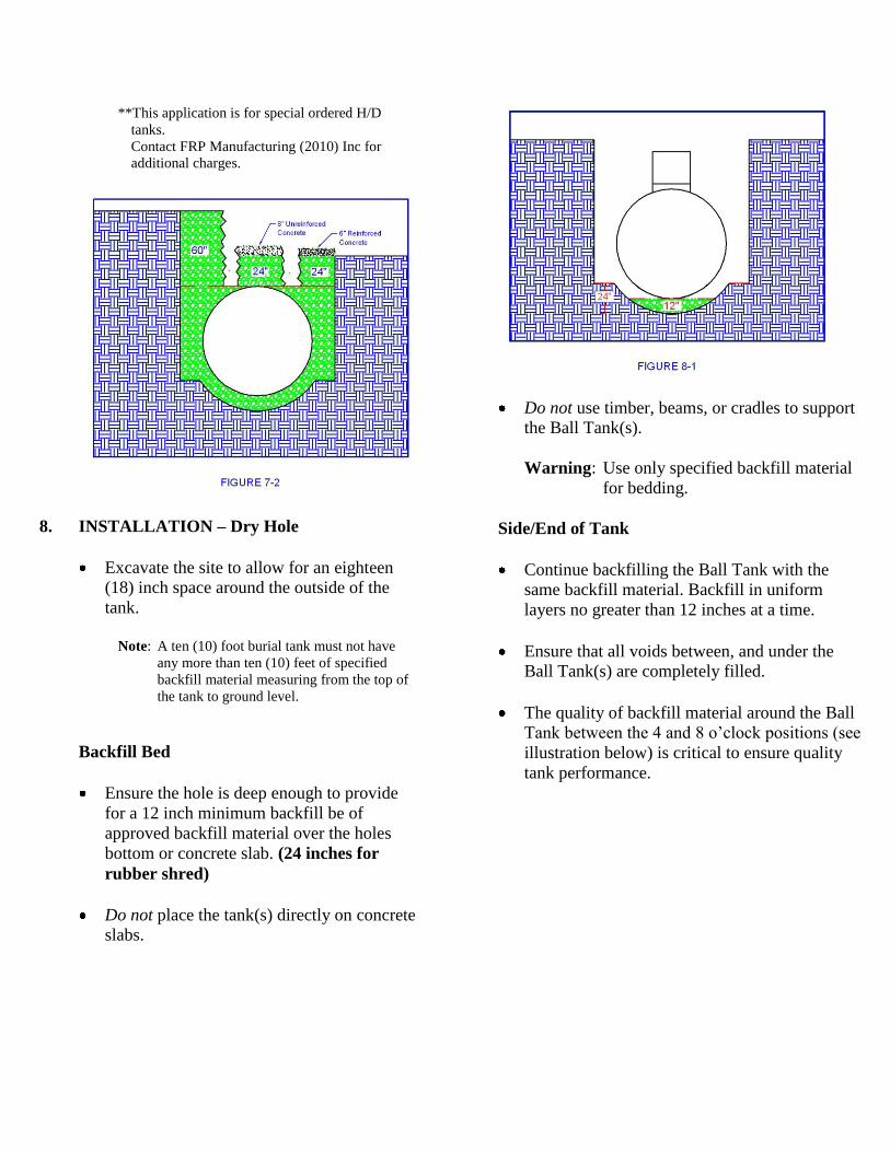
**This application is for special ordered H/D
tanks.
Contact FRP Manufacturing (2010) Inc for
additional charges.
8. INSTALLATION – Dry Hole
Excavate the site to allow for an eighteen
(18) inch space around the outside of the
tank.
Note: A ten (10) foot burial tank must not have
any more than ten (10) feet of specified
backfill material measuring from the top of
the tank to ground level.
Backfill Bed
Ensure the hole is deep enough to provide
for a 12 inch minimum backfill be of
approved backfill material over the holes
bottom or concrete slab. (24 inches for
rubber shred)
Do not place the tank(s) directly on concrete
slabs.
Do not use timber, beams, or cradles to support
the Ball Tank(s).
Warning: Use only specified backfill material
for bedding.
Side/End of Tank
Continue backfilling the Ball Tank with the
same backfill material. Backfill in uniform
layers no greater than 12 inches at a time.
Ensure that all voids between, and under the
Ball Tank(s) are completely filled.
The quality of backfill material around the Ball
Tank between the 4 and 8 o’clock positions (see
illustration below) is critical to ensure quality
tank performance.

Top of Tank
Continue backfilling with the same backfill
material above the top of the tank in 12 inch lifts
until ground requirements are met. (If utilizing
rubber shred, 24” of rubber shred is required
above the top of the tank)
Warning: Do not allow vehicle traffic or heavy
loads to go across the tank; this will
void the warranty!
Contact FRP Manufacturing (2010) Inc for special
order Ball Tanks that can accommodate traffic,
extreme conditions or any other adverse situations
to which the tank may be subjected.
Rubber shred fill:
FRP Manufacturing (2010) Inc Ball tanks
have been tested and approved to be
backfilled with recycled rubber chips.
Rubber shred is available through
numerous vendors throughout the
provinces. Acceptable size of shred is
between 2” and 5”.
Requirements for rubber shred backfill:
- Under the Ball Tank(s), the bed thickness
must be at least 24 inches thick over native
soil or concrete slab.
-Minimum 12 inches of shred must surround
tank on all sides.
-Minimum 24” of rubber shred above the tank
prior to utilizing native fill.
9. INSTALLATION – Wet Hole
Water Level, Pumping, Bed
Excavate pumpout wells at the corners of
excavation to keep the water below the tank
bottom.
Install a 12 inch bed of specified backfill
material and position the tank on the bed.
If extremely difficult water conditions at the site
are suspected, such as underground streams,
surface run-off locations, shorelines or wide
fluctuations in water level, etc., increase the bed
thickness to 18 inches and clearances between
the tank and hole walls to a minimum of 18
inches.

Ballasting
If the ground water level is expected to
exceed the tank bottom level at any stage of
the backfilling process, ballasting will be
necessary until the tank is anchored and
buried to grade.
The tank must not float after commencement
of the backfilling process.
The water ballasting level in the tank must
not be higher than 24 inches above the water
level in the hole.
A lifting cable may be used to guide the Ball
Tank during the sinking process but it must
not become tightened to excessively load the
lugs.
Backfilling
Make sure that the minimum required
clearances are maintained before starting to
backfill. See Section 4.
Proceed with the backfilling processes as per the
dry hole installations instructions mentioned
earlier using only specified backfill material.
To prevent the tank from floating during spring
thaw or high water table condition, leave the
tank approximately 1/3 full over the winter
months. This weight will keep the tank in place.
Freezing of sewage or water when the tank is
1/3 full will not affect the tank since ice will
have room to expand beyond the 1/3 level. Do
not allow liquid to freeze beyond the 1/3 full
level!
10. INSTALLATION – Freezing Weather
To ensure the bed is not frozen under the tank,
the aggregate must be free flowing without the
use of calcium chloride. Under such conditions,
the backfilling process should be completed
within one working day.
Backfill material that has frozen into lumps
must be completely thawed first, before being
used as backfill. (Caution: Steaming may cause
subsequent refreezing of fill material).
The bottom of the excavation must also be free
of frost and the walls of the excavation free of
snow and ice.

11. ANCHORING
General
The decision whether or not to anchor the
tank and the selection of the anchoring
method is the sole responsibility of the
owner.
Consider using concrete deadmen or pads if
there is a problem with extreme water levels
when installing the tank.
Anchoring the tank down will help prevent
any chance of the tank floating due to the
hydraulic effect of ground water when it is
empty.
For severe water conditions or ground
movement, a heavy duty (H/D) Ball Tank
must be installed to handle the increase in
ground water pressure. In addition, the tank
must remain at least 1/3 full at all times.
Anchoring shall be engineered based upon
tank size, ground cover, water table
elevation and calculated uplift force on the
empty tank.
Use of Deadmen
Deadmen are typically reinforced concrete
beams. You may purchase deadmen if each
section contains at least two balance points.
Lay the deadmen in the excavation parallel
to the tank and outside of the tank
“shadow”.
Install the bottom of the concrete deadmen
at the same elevation as the bottom of the
tank.
The Ball Tank and the deadmen should not
come in contact with each other. Instead,
provide sufficient clearance to allow the
deadmen to be set outside the tank “shadow”.
Use of Anchor Pad
An anchor pad is typically a reinforced concrete
base.
The total length of the slab must extend at least
18 inches beyond the tank in all directions.
The thickness of the reinforced slab should be at
least eight (8) inches thick.
Provide a separate anchor point for each hold
down cable.
Allow for sufficient depth in the excavation
for at least 12 inches of approved Bedding
Material between the base of the tank and
the anchor slab.
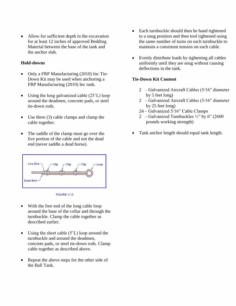
Hold-downs
Only a FRP Manufacturing (2010) Inc Tie-
Down Kit may be used when anchoring a
FRP Manufacturing (2010) Inc tank.
Using the long galvanized cable (25’L) loop
around the deadmen, concrete pads, or steel
tie-down rods.
Use three (3) cable clamps and clamp the
cable together.
The saddle of the clamp must go over the
live portion of the cable and not the dead
end (never saddle a dead horse).
With the free end of the long cable loop
around the base of the collar and through the
turnbuckle. Clamp the cable together as
described earlier.
Using the short cable (5’L) loop around the
turnbuckle and around the deadmen,
concrete pads, or steel tie-down rods. Clamp
cable together as described above.
Repeat the above steps for the other side of
the Ball Tank.
Each turnbuckle should then be hand tightened
to a snug position and then tool tightened using
the same number of turns on each turnbuckle to
maintain a consistent tension on each cable.
Evenly distribute loads by tightening all cables
uniformly until they are snug without causing
deflections in the tank.
Tie-Down Kit Content
2 – Galvanized Aircraft Cables (5/16” diameter
by 5 feet long)
2 – Galvanized Aircraft Cables (5/16” diameter
by 25 feet long)
24 – Galvanized 5/16” Cable Clamps
2 – Galvanized Turnbuckles ½” by 6” (2600
pounds working strength)
Tank anchor length should equal tank length.