TABLE OF CONTENTS – FRP CHEMICAL STORAGE...
12
TABLE OF CONTENTS – FRP CHEMICAL STORAGE TANKS Chemical Storage Tank Capabilities and Variations 1 Reinforced Thermoset Polyester and Vinylester (RTP) Tank Specification 2 ASTM D 2563 Visual Defect Table 8 RTP Visual Inspection Acceptance Criteria 9 Nozzle Detail Drawing 11
Transcript of TABLE OF CONTENTS – FRP CHEMICAL STORAGE...

TABLE OF CONTENTS – FRP CHEMICAL STORAGE TANKS
Chemical Storage Tank Capabilities and Variations 1
Reinforced Thermoset Polyester and Vinylester (RTP) Tank Specification
2
ASTM D 2563 Visual Defect Table 8
RTP Visual Inspection Acceptance Criteria 9
Nozzle Detail Drawing 11

1 FRP Chemical Storage Tanks
620 North Post Street • Post Falls, ID 83854 • 208.777.7444 ph 208.777.7445 fax • www.spunstrand.com
Chemical Storage Tank Capabilities and Variations
With the 2003 acquisition of an existing FRP Tank manufacturing company, Spunstrand®
Inc. added significant large diameter filament winding capability, which enhances our
product offering significantly. Spunstrand® Inc. now has a dedicated facility for
manufacturing chemical and water storage tanks, carbon scrubbers and custom FRP
products that will serve our primary industrial and municipal customers as well as emerging
markets.
FRP tanks have a wide variety of applications, and the below list is only a small example of
the many applications that should be explored.
• Chemical storage (semi-conductor industry, wastewater treatment, water treatment,
plating, oil fields, aerospace, food processing, leachate tanks, etc.)
• Water storage (fire water cisterns, potable water storage, chiller water storage, etc.)
• Chemical Vats (specialty plating operations)
Our tanks are custom configured to our customer’s specific applications, including resin and
liner recommendations, fitting locations and any other job-related needs. Available options
include stiffening ribs for buried tank applications, insulated tanks, sloped bottoms, and any
other customer exacting requests to best suit their application.
Our facility has a customized cantilevered 12’ diameter mandrel that allows us to
manufacture this specific size of tank with the tank bottom and sidewall integrally molded for
the highest level of corrosion resistance. While this option is limited to this one specific
size, it does offer a premium option for highly corrosive applications such as Sodium
Hypochlorite storage tanks. We also have special equipment that allows us to easily
product tanks with a BPO/DMA curing system for applications where traditional cure
systems are not recommended.
Spunstrand® Inc. has many other options available to match our customer’s specific needs.
Please contact us for further information on your FRP storage tank application.

2 FRP Chemical Storage Tanks
Spunstrand® Inc. Specification - 11/1/09 - Version: 1.1
SAMPLE SPECIFICATION FOR REINFORCED THERMOSET POLYESTER AND VINYLESTER (RTP) TANKS
Products 2.01 General A. Reinforced thermoset polyester (RTP) tanks as manufactured by Spunstrand Inc®, and
shall be used to store liquid chemicals, waste water, or process solutions as shown on schedules and drawings.
B. Tank Dimensions and Capacity: Equipment# Chemical Diameter Strt Shell Hgt Liquid Depth Gallon Capacity T-001 Misc 3’∅-14’∅ 20’+ TBD TBD 2.02 Design Criteria: 1. Seismic zone 3. 2. Live loading: a. Internal pressure above liquid surface: Atmospheric b. Domed top, psf 100 psf 3. Process: a. Liquid: Example - Sodium Hydroxide, 25%, specific gravity: 1.27, pH:14. 4. Temperature, degrees F: 50 -105. 5. A minimum structural safety factor of 5 shall be used in the design of the Vessel. 6. Allowable strain for the tanks: 0.0010 in./in. 7. Two lifting lugs per tank, minimum. 2.03 Materials A. FRP Vessel 1. Type: Filament wound rated at design pressures indicated in the drawings.
Minimum wall thickness shall be .250. Wall thickness increases to be determined by diameter and height. Chop hoop winding may only be bid as an alternate.
2. Grade: Type 1, Grade 2 (VE) RTRP, Class V per ASTM D3299-88 and D2996. 3. Vessel shall be designed for not less than the internal pressure and loads as in
design criteria. 4. Tank top and bottom shall be fabricated and joined by contact molding.

3 FRP Chemical Storage Tanks
Spunstrand® Inc. Specification - 11/1/09 - Version: 1.1
5. The resin used shall be Hetron 992SB selected to meet the exposures and
temperatures of chemical to be stored. Fillers other than antimony pentoxide added for flame retardance when required, shall not be allowed, and should not exceed 3% by weight. A thixotropic agent for viscosity control may be used as recommended by the resin manufacturer. No thixotropic agent is to be used in the corrosion liner or on surfaces to be in contact with the corrosive environment. Catalyst shall be DDM9 or High Point 90 as recommended by Ashland Chemicals.
2.04 Laminate Construction 1. Tank Construction – The laminate comprising the structural tank (cylindrical shell, flat bottom, and domed heads) shall consist of a corrosion-resistant laminate comprised of a corrosion liner, corrosion barrier and a structural layer. 2. Corrosion Liner: Inner surface shall contain two (2) layers of a 10 mil thick minimum
C-glass surfacing veil, saturated with vinylester resin. The surface veil shall be overlapped a minimum of 1". Surface veil layers shall be followed by two (2) layers of 1-1/2 oz./sq. ft. chopped strand mat. Corrosion liner is to gel completely before proceeding with structural laminates. In no case shall the interruption exceed 24 hours. Total minimum liner thickness to be 100 mils. No thixotropic agent or fire retardant additive is to be used in the liner resin. Corrosion liner shall contain not less than 20 % nor more than 30% glass by weight. The liner shall pass inspection for ASME RTP-1 Table 6-1 visual acceptance criteria. BPO curing is an option depending on chemical exposure and concentration.
3. Structural layer shall be filament wound of Hetron 992SB premium grade vinylester
resin with 3% Antimony Pentoxide and Type E 250 strand yield continuous glass roving. Filament winding cycle thickness to be 0.06" maximum. Glass content 55 to 65 %. Winding angle shall be 70° to 80°. Chopped hoop winding and hand lay-up will not be allowed in the structural layers. Minimum barcol hardness shall be 36 for all laminates.
Exterior of all laminates shall contain a 10 mil A-veil and sufficient resin to insure a
relatively smooth surface free from exposed glass fibers or sharp projections. Scrubber vessels located outdoors shall contain an exterior colored surface coat. An ultraviolet stabilizer added to the final coat of resin that also incorporates paraffinated wax curing elements. Color to be selected by owner from Spunstrand Inc. color chart.
The manways shall be flanged and drilled per ANSI 16.5, 150 lb. Domed ends shall be factory attached and constructed to the same liner and
structural wall thickness. Chopper gun or hand-lay-up methods are acceptable so long as there is no antimony added to the 100 mil liner.
Interior of the tank floor shall be flat, or sloped to allow complete drainage of the
tank. Vessel shall be equipped with a 2” eccentric or siphon drain located as low as
possible on the tank wall.
4 FRP Chemical Storage Tanks
Spunstrand® Inc. Specification - 11/1/09 - Version: 1.1
Equip tank with a vertical clear strip extending from the top of the tank to the bottom. Form the clear strip by not coating a 6” wide strip with the pigmented exterior coating. The clear strip to have only the color of the resin used in the tank construction. If site glasses, or ultra sonic level are used, the clear strip is eliminated. Any site glasses shall be installed with ball valves top and bottom.
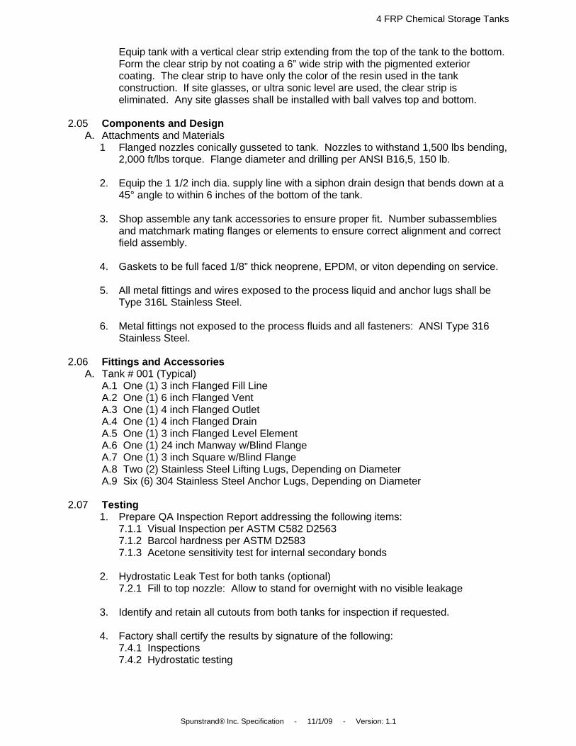
2.05 Components and Design A. Attachments and Materials 1 Flanged nozzles conically gusseted to tank. Nozzles to withstand 1,500 lbs bending,
2,000 ft/lbs torque. Flange diameter and drilling per ANSI B16,5, 150 lb. 2. Equip the 1 1/2 inch dia. supply line with a siphon drain design that bends down at a
45° angle to within 6 inches of the bottom of the tank. 3. Shop assemble any tank accessories to ensure proper fit. Number subassemblies
and matchmark mating flanges or elements to ensure correct alignment and correct field assembly.
4. Gaskets to be full faced 1/8” thick neoprene, EPDM, or viton depending on service. 5. All metal fittings and wires exposed to the process liquid and anchor lugs shall be
Type 316L Stainless Steel. 6. Metal fittings not exposed to the process fluids and all fasteners: ANSI Type 316
Stainless Steel. 2.06 Fittings and Accessories A. Tank # 001 (Typical) A.1 One (1) 3 inch Flanged Fill Line A.2 One (1) 6 inch Flanged Vent A.3 One (1) 4 inch Flanged Outlet A.4 One (1) 4 inch Flanged Drain A.5 One (1) 3 inch Flanged Level Element A.6 One (1) 24 inch Manway w/Blind Flange A.7 One (1) 3 inch Square w/Blind Flange A.8 Two (2) Stainless Steel Lifting Lugs, Depending on Diameter A.9 Six (6) 304 Stainless Steel Anchor Lugs, Depending on Diameter 2.07 Testing 1. Prepare QA Inspection Report addressing the following items: 7.1.1 Visual Inspection per ASTM C582 D2563 7.1.2 Barcol hardness per ASTM D2583 7.1.3 Acetone sensitivity test for internal secondary bonds 2. Hydrostatic Leak Test for both tanks (optional) 7.2.1 Fill to top nozzle: Allow to stand for overnight with no visible leakage 3. Identify and retain all cutouts from both tanks for inspection if requested. 4. Factory shall certify the results by signature of the following: 7.4.1 Inspections 7.4.2 Hydrostatic testing

5 FRP Chemical Storage Tanks
Spunstrand® Inc. Specification - 11/1/09 - Version: 1.1
2.08 Marketing / Nameplate Seal label into laminate exterior with clear resin with the following information:
A. Fabricator’s Name B. Gallon Capacity C. Maximum Temperature D. Design Pressure / Vacuum E. Specific Gravity F. PH G. Resin H. Minimum Thickness I. Tank Number J. Tank Name K. Date Manufactured
2.09 Shop Drawings / Calculations 1. Calculation sheets for Tank #001 shall be included with the drawings and stamped by a Washington professional engineer. 2. Attached drawings for Tank #001 shall be to scale with complete nozzle and attachment schedule.
6 FRP Chemical Storage Tanks
Spunstrand® Inc. Specification - 11/1/09 - Version: 1.1
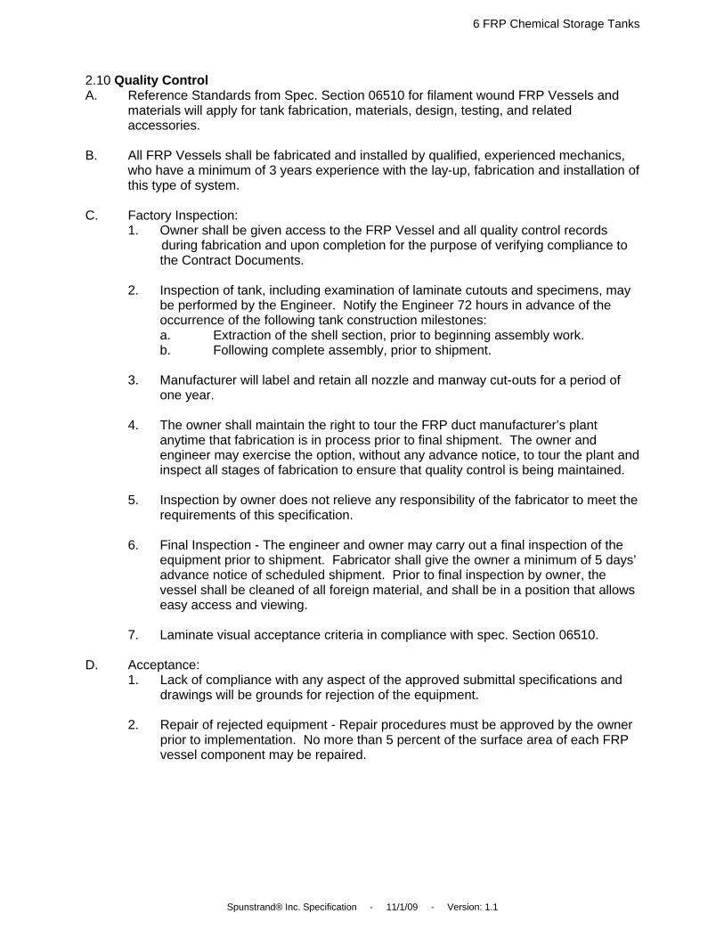
2.10 Quality Control A. Reference Standards from Spec. Section 06510 for filament wound FRP Vessels and
materials will apply for tank fabrication, materials, design, testing, and related accessories.
B. All FRP Vessels shall be fabricated and installed by qualified, experienced mechanics,
who have a minimum of 3 years experience with the lay-up, fabrication and installation of this type of system.
C. Factory Inspection: 1. Owner shall be given access to the FRP Vessel and all quality control records during fabrication and upon completion for the purpose of verifying compliance to
the Contract Documents. 2. Inspection of tank, including examination of laminate cutouts and specimens, may
be performed by the Engineer. Notify the Engineer 72 hours in advance of the occurrence of the following tank construction milestones:
a. Extraction of the shell section, prior to beginning assembly work. b. Following complete assembly, prior to shipment. 3. Manufacturer will label and retain all nozzle and manway cut-outs for a period of
one year. 4. The owner shall maintain the right to tour the FRP duct manufacturer’s plant
anytime that fabrication is in process prior to final shipment. The owner and engineer may exercise the option, without any advance notice, to tour the plant and inspect all stages of fabrication to ensure that quality control is being maintained.
5. Inspection by owner does not relieve any responsibility of the fabricator to meet the
requirements of this specification. 6. Final Inspection - The engineer and owner may carry out a final inspection of the
equipment prior to shipment. Fabricator shall give the owner a minimum of 5 days’ advance notice of scheduled shipment. Prior to final inspection by owner, the vessel shall be cleaned of all foreign material, and shall be in a position that allows easy access and viewing.
7. Laminate visual acceptance criteria in compliance with spec. Section 06510. D. Acceptance:
1. Lack of compliance with any aspect of the approved submittal specifications and drawings will be grounds for rejection of the equipment.
2. Repair of rejected equipment - Repair procedures must be approved by the owner
prior to implementation. No more than 5 percent of the surface area of each FRP vessel component may be repaired.

7 FRP Chemical Storage Tanks
Spunstrand® Inc. Specification - 11/1/09 - Version: 1.1
2.11 Submittals A. Provide the following information in addition to the standard submittal requirements with
the Bid: 1. The fabricator shall submit for approval all reference standards, calculations, fabrication
drawings, and all engineering details of the tank design prior to beginning fabrication.
A. The submittal should include all information utilized by the fabricator which describes specifically how their FRP vessels are manufactured. This should be in the form of shop drawings, standards, specifications, other shop instructions and QC records. This should include, but not be limited to:
1.) Resin Type 2.) Types and amounts of filler. 3.) Corrosion liner description 4.) Reinforcement types for hand lay-up or chopped laminates. 5.) For filament-wound laminates: a.) Helix angle b.) Glass content range c.) Strand yield d.) Strand by inch in the winding band. e.) Ply thickness f.) Amount of chop or unidirectional roving interspersed with
winding, if any, and location within laminate. 6.) For all fabricated parts. a.) Construction type b.) Laminate thickness c.) Ply sequences d.) Glass content range B. Recommended procedure for the protection and handling of tanks prior to installation. C. Complete design calculations for tank signed by a structural engineer registered in the State of Washington, verifying that the tank has been designed to meet all design criteria given in spec. section 13206, 06510 and seismic zone 3. 1. Anchor bolting template for tank. 2. Resin Manufactures verification of compatibility. 3. Manufactures available gel coat colors. D. Complete O&M manuals to be delivered to contractor within 14 days of vessel delivery.
8 FRP Chemical Storage Tanks
Spunstrand® Inc. Specification - 11/1/09 - Version: 1.1
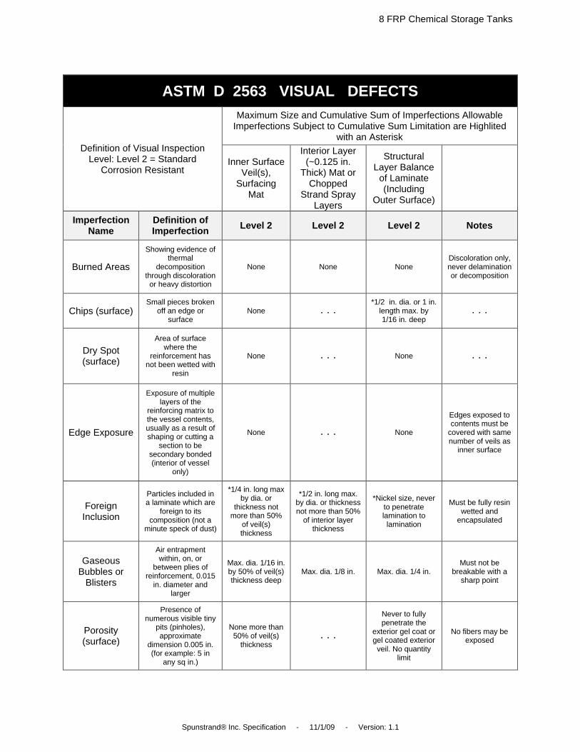
ASTM D 2563 VISUAL DEFECTS
Definition of Visual Inspection Level: Level 2 = Standard
Corrosion Resistant
Maximum Size and Cumulative Sum of Imperfections Allowable Imperfections Subject to Cumulative Sum Limitation are Highlited
with an Asterisk
Inner Surface Veil(s),
Surfacing Mat
Interior Layer (~0.125 in.
Thick) Mat or Chopped
Strand Spray Layers
Structural Layer Balance
of Laminate (Including
Outer Surface)
Imperfection Name
Definition of Imperfection Level 2 Level 2 Level 2 Notes
Burned Areas
Showing evidence of thermal
decomposition through discoloration or heavy distortion
None None None Discoloration only, never delamination or decomposition
Chips (surface) Small pieces broken
off an edge or surface
None . . . *1/2 in. dia. or 1 in.
length max. by 1/16 in. deep
. . .
Dry Spot (surface)
Area of surface where the
reinforcement has not been wetted with
resin
None . . . None . . .
Edge Exposure
Exposure of multiple layers of the
reinforcing matrix to the vessel contents, usually as a result of shaping or cutting a
section to be secondary bonded (interior of vessel
only)
None . . . None
Edges exposed to contents must be
covered with same number of veils as
inner surface
Foreign Inclusion
Particles included in a laminate which are
foreign to its composition (not a
minute speck of dust)
*1/4 in. long max by dia. or
thickness not more than 50%
of veil(s) thickness
*1/2 in. long max. by dia. or thickness not more than 50%
of interior layer thickness
*Nickel size, never to penetrate lamination to lamination
Must be fully resin wetted and
encapsulated
Gaseous Bubbles or
Blisters
Air entrapment within, on, or
between plies of reinforcement, 0.015
in. diameter and larger
Max. dia. 1/16 in. by 50% of veil(s) thickness deep
Max. dia. 1/8 in. Max. dia. 1/4 in. Must not be
breakable with a sharp point
Porosity (surface)
Presence of numerous visible tiny
pits (pinholes), approximate
dimension 0.005 in. (for example: 5 in
any sq in.)
None more than 50% of veil(s)
thickness . . .
Never to fully penetrate the
exterior gel coat or gel coated exterior veil. No quantity
limit
No fibers may be exposed

9 FRP Chemical Storage Tanks
Spunstrand® Inc. Specification - 11/1/09 - Version: 1.1
RTP VISUAL INSPECTION ACCEPTANCE CRITERIA
Definition of Visual Inspection Levels (to be specified by User
or User’s Agent): Level (1) = Critically Corrosion Resistant,
Level (2) = Standard Corrosion Resistant
Maximum Size and Cumulative Sum of Imperfections Allowable [After Repair. See General Notes (a) and (b). Imperfections Subject to
Cumulative Sum Limitation are Highlighted with an Asterisk.]
Notes Inner Surface Veils(s), Surfacing Mat
Interior Layer (-0.125 in Thick) Mat or Chopped Strand Spray Layers
Structural Layer Balance of Laminate (Including
Outer Surface)
Imperfection Name
Definition of Imperfection Level (1) Level (2) Level (1) Level (2) Level (1) Level (2)
Scratches (surface)
Shallow marks, grooves,
furrows, or channels caused by improper handling
*None *None . . . . . . *None
more than 6 in. long
*None more than 12 in. long
No fibers may be exposed
Wet Blisters (surface)
Rounded elevations of the surface, somewhat
resembling a blister on the human skin;
not reinforced
*None over 3/16 in. dia. by 1/16 in. in height
*None over 3/16 in. dia. by 1/16 in. in height
. . . . . . < . . . No Limit . . . >
Must be fully resin filled; no drips loosely
glued to surface,
which are to be removed
Wet-out Inadequate
Resin has failed to saturate
reinforcing (particularly
woven roving)
None None None None
Dry mat or prominent and dry woven roving pattern
not acceptable; discernible but fully
saturated woven pattern acceptable
Split tests on cutouts may be used to
discern degree of
saturation on reinforcing
layers
Wrinkles and Creases
Generally linear, abrupt changes in
surface plane caused by laps of reinforcing
layers, irregular mold
shape, or mylar overlap
Max. deviation
20% of wall or 1/16 in., whichever
is least
Max. deviation
20% of wall or 1/8 in., whichever
is least
. . . . . . Max. deviation 20% of
wall or 1/8 in., whichever is least
Not to cause a cumulative linear defect
(outside defect adding
to inside defect)
Dry Spot (surface)
Area of surface where the
reinforcement has not been wetted with
resin
None None . . . . . . None None . . .
Edge Exposure
Exposure of multiple layers
of the reinforcing
matrix to the vessel
contents, usually as a
result of shaping or cutting a
section to be secondary
bonded (interior of
vessel only)
None None . . . . . . None None
Edges exposed to
contents must be covered with same number of
veils as inner surface

10 FRP Chemical Storage Tanks
Spunstrand® Inc. Specification - 11/1/09 - Version: 1.1
RTP VISUAL INSPECTION ACCEPTANCE CRITERIA CONT’D
Definition of Visual Inspection Levels (to be specified by User
or User’s Agent): Level (1) = Critically Corrosion Resistant,
Level (2) = Standard Corrosion Resistant
Maximum Size and Cumulative Sum of Imperfections Allowable [After Repair. See General Notes (a) and (b). Imperfections Subject to
Cumulative Sum Limitation are Highlighted with an Asterisk.]
Notes Inner Surface Veils(s), Surfacing Mat
Interior Layer (-0.125 in Thick) Mat or Chopped Strand Spray Layers
Structural Layer Balance of Laminate (Including
Outer Surface)
Imperfection Name
Definition of Imperfection Level (1) Level (2) Level (1) Level (2) Level (1) Level (2)
Foreign Inclusion
Particles included in
laminate which are foreign to
its composition (not a minute speck of dust)
*3/16 in. long max. by dia. or thickness not more than 30% of veil(s) thickness
*1/4 in. long max. by dia. or
thickness not more than 50% of veil(s) thickness
*1/2 in. long max. by dia. or thickness not more than 30% of veil(s) thickness
*1/2 in. long max. by dia. or thickness not more than 50% of veil(s) thickness
*Dime size never to
penetrate lamination
to lamination
*Nickel size never to
penetrate lamination
to lamination
Must be fully resin wetted
and encapsulated
Gaseous Bubbles or
Blisters
Air entrapment within, on, or between plies
of reinforcement, 0.015 in. dia.
and larger
Max. dia. 1/16 in. by
30% of veil(s)
thickness deep
Max. dia. 1/16 in. by
50% of veil(s)
thickness deep
Max. dia. 1/3 in.
Max. dia. 1/8 in.
Max. dia. 3/16 in.
Max. dia. 1/4 in.
Must not be breakable
with a sharp point
< . . . Refer to User’s Specifications for Quantity Limitations . . . >
Pimples (surface)
Small, sharp, conical
elevations on the surface of
a laminate
*Max. height or
dia. 1/64 in.
*Max. height or
dia. 1/32 in. . . . . . . < . . . No Limit . . . >
Must be fully resin filled
and wetted: generally, captured
sanding dust
Pit (surface) Small crater in the surface of
a laminate
*1/8 in. dia. max. by 30% of veil(s)
thickness max.
*1/8 in. dia. max. by 50% of veil(s)
thickness max.
. . . . . .
*1/4 in. dia. max X 1/16
in. deep max.
*1/4 in. dia. max X 3/32
in. deep max.
No fibers may be exposed
Porosity (surface)
Presence of numerous
visible tiny pits (pinholes),
approx. dimension
0.005 in. (for example, 5 in.
any sq. in.)
None more than 30% of veil(s) thickness
None more than 50% of veil(s) thickness
. . . . . .
None to fully penetrate the exterior gel coat or gel
coated exterior veil. No quantity limit
No fibers may be exposed
Allowable Cumulative
Sum of Highlighted
Imperfections
Maximum allowable in any sq. ft. Maximum
allowable in any sq. yd.
3 sq. ft. 15 sq. yd.
5 sq. ft. 20 sq. yd
3 sq. ft. 20 sq. yd.
5 sq. ft. 30 sq. yd
5 sq. ft. 30 sq. yd
5 sq. ft. 40 sq. yd . . .
Maximum % Repairs
The maximum allowable area
of repairs made in order to pass visual
inspection
3% 10% 3% 10%
3% structural, no limit to
outer surface repairs
10% structural, no limit to
outer surface repairs
Debond tests required prior
to inner surface repairs
GENERAL NOTES:
(a) Above acceptance criteria apply to condition of laminate after repair and hydrotest. (b) Noncatalyzed resin in not permissible to any extent in any area of the laminate. (c) Refer to Appendix M-9 for rules on repairs.

11 FRP Chemical Storage Tanks
Spunstrand® Inc. Specification - 11/1/09 - Version: 1.1