BAE, Choongsik - OSTI.GOV
33
BAE, Choongsik Engine Laboratory Department of Mechanical Engineering, KAIST KAIST Korea Advanced Institute of SoleAte and T>: t hnoingy Cerc
Transcript of BAE, Choongsik - OSTI.GOV

BAE, ChoongsikEngine Laboratory
Department of Mechanical Engineering, KAIST
KAIST Korea Advanced Institute of Sole Ate and T>: t hnoingy Cerc

Backgroundy
Objectivey
Experimental Resulty
Conclusiony

ackground Homogeneous Charge Compression Ignition
nn
h#
Diesel Engine(compression ignition}
Gasoline Engine(homogeneous premixed charge)
HCCI Engine(Homogeneous Charge Compression Ignition)
3

Background - Advantages & Disadvantages
□ Advantages and disadvantages of HCCI engine
HCCIEngine
Advantages
Usage of the different type of fuels
Ultra low NOx & PM emissions
Improved fuel economy
Excessive combustion rate
Engine noise
HC and CO emissions
HCCIEngine
Disadvantages

r V
Increase of Negative
work
Y
Ja
I—BMBIH rj Co IHW
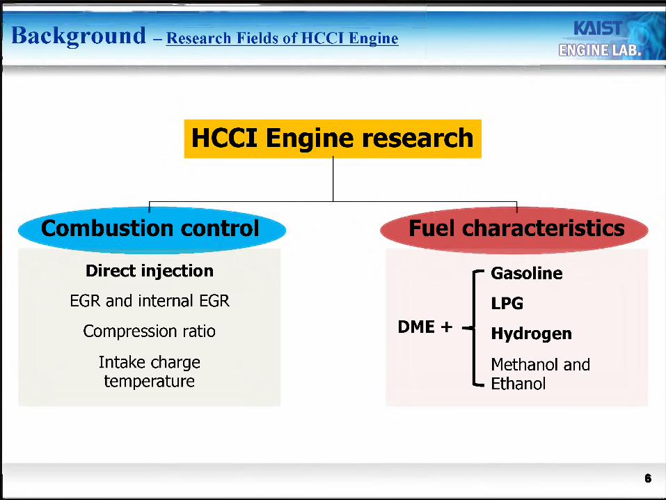
Background - Research Fields of HCCI Engine
HCCI Engine research
i
Combustion control
Direct injection
EGR and internal EGR
Compression ratio
Intake charge temperature
1
Fuel characteristics
r Gasoline
DME + —LPG
Hydrogen
Methanol and Ethanol
6

Anti-knock property
Extend high load limit
LPC.Caolinc.Hydrogen
y
LPG
-42.07 Boiling temperature (°C) -0.5KC\A 1 nnitinn lomnarafnro
•-v v v
114 Octane number 91

Dual-Fuel HCCI CombustionBased on SI Engine
- LPG Port and DME Direct HCCI- Comparing Propane and Butane

Experimental apparatus
Nitre gen
*1
Nitroga
i L
DME
LPG Proyamm able ECUu
-tSs*'
0
Programmable ECU
Proyamm able ECU
Comb u*tion Pm: smj i c Trait
rLdmbtiu meter (LA4)
LxKdutlPressure ^jaye
Exhaust Gas Emission
(MEXAl 50CD)
Number of Cylinder 1
Bore (mm) 82
Stroke (mm) 93.5
Displacement volume (cc)
493.7
Compression ratio 13.0
RPIH 1000
Intake Valve Open (CAD)*
1
AC Dynamometer
9
Mot
ored
in-c
ylin
der p
ress
ure
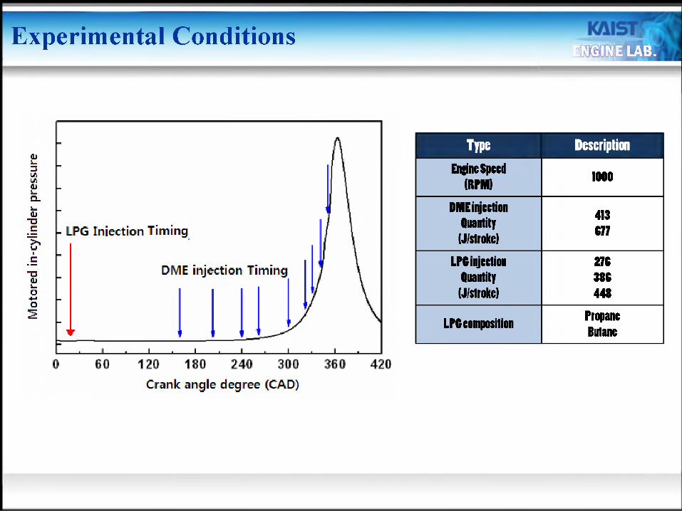
Experimental ConditionsiNESE LAB.
- LPG Injection Timing
DIME injection Timing
120 180 240 300
Crank angle degree (CAD)
Engine Speed(RPIM)
IQQQ
DME injection Quantity
(J/stroke)
413677
LPC injection 276Quantity 386
(J/stroke) 448
LPC composition PropaneButane

Experimental Result and Discussion
Output Performance - Indicated Mean Effective Pressure (IMEP)
DIKE combusted with Propane, Butane
DME injection: 413 J/stroke, at Optimal timing (240 CAD)
IMEP was decreased In spite ofincrcascd Injection propane quantity
280 320 360 400 440
LPG injection quantity (J/stroke)
• The maximum IMEP was increased around 360 kPa• Average IMEP was higher when propane was used
PropaneButane
400 -
350 -
300 -
1
J
Experimental Result and Discussion
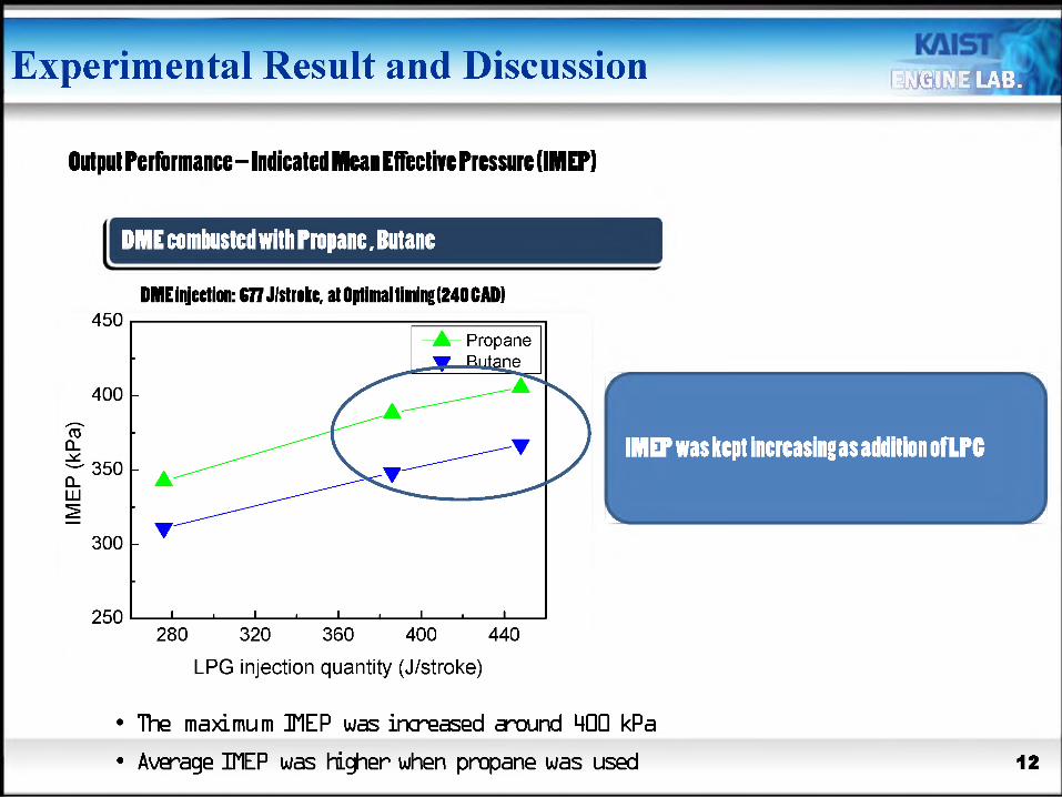
Output rcrfonnancc—lidlcatcd RHeai Effective Pressure (IMEP)
DIRE combusted wltlPmpanc, Butane
DIME injection: 677 J/strokc, at Optimal timing (240CAD)
Propane
400 -
350 -
300 -
LPG injection quantity (J/stroke)
W m
IMEP was kept increasing as addition ofLPG
Si H
• The maximum IMEP was increased around 400 kPa
• Average IMEP was higher when propane was used 12

Experimental Result and Discussion
Output rcrfonnancc—lidlcatcd RHeai Effective Pressure (IMEP)
8.0
7.0ro
CL 6.0
2 5.03V)V) 4.02
Q_t— 3.0d)"Oc 2.0
o 1.0c
0.0
Increased ignition May ■> Portion of positive work is increased
6z
Propane : 276 J/stroke 'T TTTT Butane: 276 J/stroke o, J/stroke
13 J/stroke
330 Soppressed entire combustion reaction -> Total amount of work is decreased
380 390
• AdditLotV-hi i ru ■ inirucKjuu ±yi u.u.ui i uuiay a uuimjckjuu iii am iiiu iii pr hmmlv u
• Better anti-knocking property of propane -> More suppression of combustion
P
13
Experimental Result and Discussion
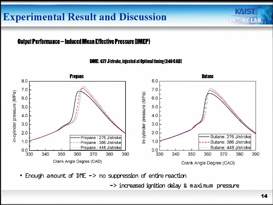
Output Performaucc - Induced Mean Effective Pressure (IMEPI
DIME: 677 J/stroke, injected at Optimal timing (240 CAD)
Propane
6.0 -
4.0 -
2.0 -
— Propane : 276 J/stroke- - Propane : 386 J/stroke
Propane : 448 J/stroke
Crank Angle Degree (CAD)
Butane
— Butane: 276 J/stroke— - Butane: 386 J/stroke— Butane: 448 J/stroke
Crank Angle Degree (CAD)
• Enough amount of DUE -> no suppression of entire reaction
-> increased ignition delay & maximum pressure
14

Experimental Result and Discussion ENGINE LAB.
Output Performance - liductd Mcai Effective Pressure (IMEP)
8.0
03CL
7.0 -
6.0 -
§ 5.01-(/)P 4.01-
o) 3.01-"OI 2 0 I-
i.or0.0
330 34C
Enough ^
Increased ignition delay, maximum pressure . maxkamn pressure rise rate
"TOrJjijjj ^ Jitiiil iJjjjJiuiJLUJ
— propane : z/o j/stroKe- - Propane : 386 J/stroke £ 1.0
TOran^TTrrl7strokeButane: 386 J/stroke
hk'strokeBO 390
Severe noise and knocking occurs
9-> increased ignition delay & maximum pressure
Summary - DME HCCI combustion in Single Fuel Engine
The effect of LPG composition in a DME-LPG dual-fueled HCCI engine at various injection quantity and injection timing was observed
1. In a DME HCCI engine, higher load limit was extended by using LPG as an ignition inhibitor
2. If injection quantity of LPG exceeds certain level compared to injected quantity of DME, IMEP was decreased
3. Propane was more effective way to increase IMEP in this study
16
Summary - DME HCCI combustion in Single Fuel EngineENGINE LAB.
Propane

Dual-Fuel HCCI CombustionBased on SI Engine
- Gasoline + DME HCCI- LPG + DME HCCI

Experimental apparatus
Pressure regulator
n
DME supplying system
Combustion
Pressure Transducer
DME direct injection system
Programmable ECU
fuel injection system
■ Lambda meter (LA4)
1----------JExhaust Pressure gauge
Exhaust Gas Emission
Analysers
(MEXA1500D)
LPG port fuefInjection system

Experimental conditions
□ Experimental conditions
Engine speed, rpm 1000
IVO [ATDC] -29, -19, -9, 1, 11
DME injection timing [ATDC]
110
^TOTAL2.12, 2.41,2.57,
2.77, 2.91
^DME 3.7
Intake air temperature, °C 30
Coolant/Oil temperature, °C 80/80
IVO timings
o.io -
0.05 -
EVC timing
-35-30-25-20-15-10 -5 0 5 10 15
DME injection timing
50 100 150 200 250 300 350 400 450 500
Crank angle degree [CAD]
20
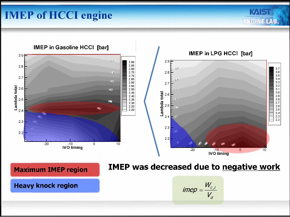
IMEP of HCCI engineENGINE LAB.
IMEP in Gasoline HCCI [bar]
IreT3-Q
Ere
2.9
IVO timing
IMEP in LPG HCCI [bar]2.9
-20 -10 0 10IVO timing
Maximum IMEP region IMEP was decreased due to negative work
Heavy knock region imep W',

Lam
bda
tota
lC02 emissions of HCCI
The difference of C02 emission [%]
-20 -10 0 10IVO timing
emission of than that of Blasolinelow carbon contained
high octane number
HCCI was HCCI
Handmi
Difference = LPG
Theemission
difference
2.
wasincreased
as theIVO timing
retardedand
Bwasdecreased
2.
- gasoline
2.La
mbd
a to
tal
Lam
bda
tota
l
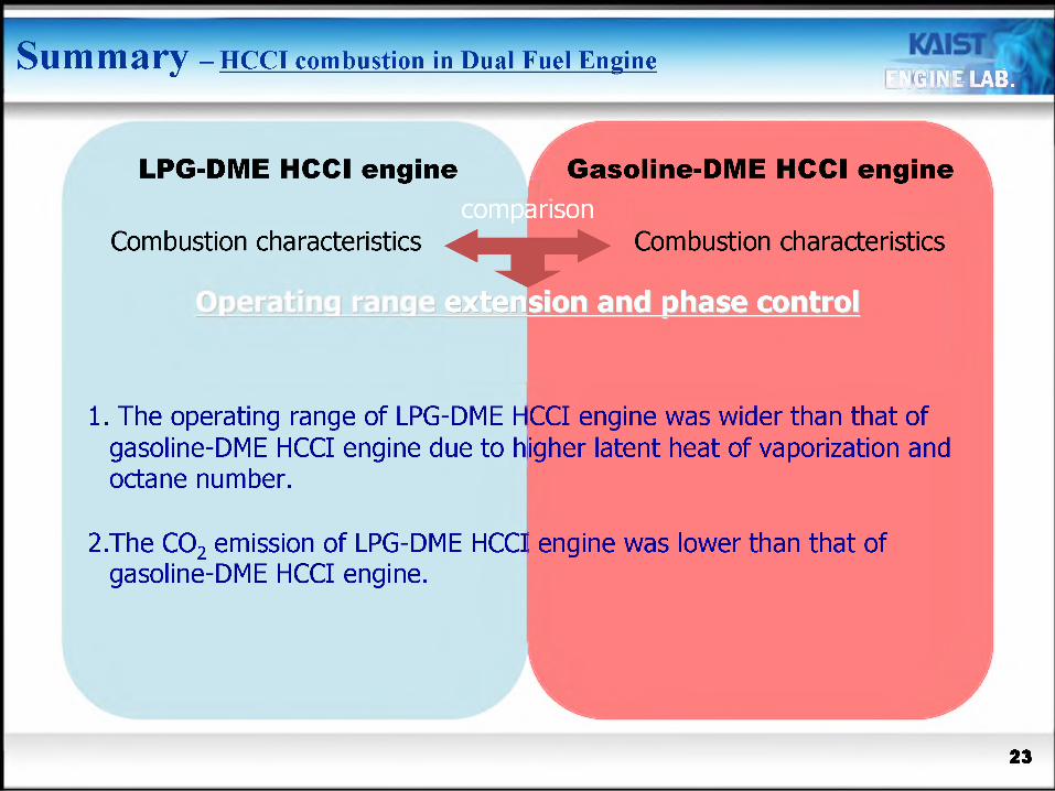
Summary - HCCI combustion in Dual Fuel EngineENGINE LAB.
LPG-DME HCCI engine
Combustion characteristics
Gasoline-DME HCCI engine
Combustion characteristics
1. The operating range of LPG-DME H gasoline-DME HCCI engine due to hi octane number.
CCI engine was wider than that of gher latent heat of vaporization and
2.The C02 emission of LPG-DME HCCI engine was lower than that of gasoline-DME HCCI engine.
23

Dual-Fuel HCCI CombustionBased on Cl Engine
- Hydrogen Port and DME Direct HCCI

Intake air diesel engine
| Common-rail injection system (igniter)ruvi injection type | | CNG injector (port fuel injection)
25
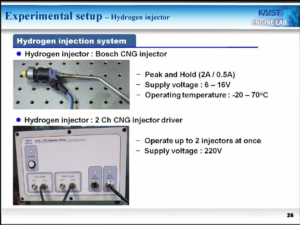
Experimental setup - Hydrogen injector
Hydrogen injection system
Hydrogen injector: Bosch CNG injector
- Peak and Hold (2A f 0.5A)- Supply voltage : 6 - 16V- Operating temperature : -20 - 70°C
Hydrogen injector: 2 Ch CNG injector driver
- Operate up to 2 injectors at once- Supply voltage : 220V

Operating conditions - Effect of DME Injection Timing
Fuel DME / H2
Engine speed 1200 rpm
Compression ratio 14.8
Load 0.2 MPa
Injection timing of DME 40-2 CAD BTDC
Injection timing of H2 360 CAD BTDC
Injection quantity of DME 5mg(fixed)
Injection quantity of H2 varied(meet 0.2MPa IMEP)
Coolant temperature 80°C
Intake air temperature 30°C
27

HR
R[J
/CA
]Experimental results - In-cylinder pressure and HRR
Engine speed: t1 intake 'IMEP:
1200rpm 30°C 0.2 MPa
• DME injection Before BTDC 10 CAD
CtenkAncJe[GAE|
- In-cylinder pressure and HRR were increased with retarding DME injection
- LTR and HTR were observed
DME injection After BTDC 10 CAD
- In-cylinder pressure and HRR were increased with advancing DME injection
- only HTR was observed
28
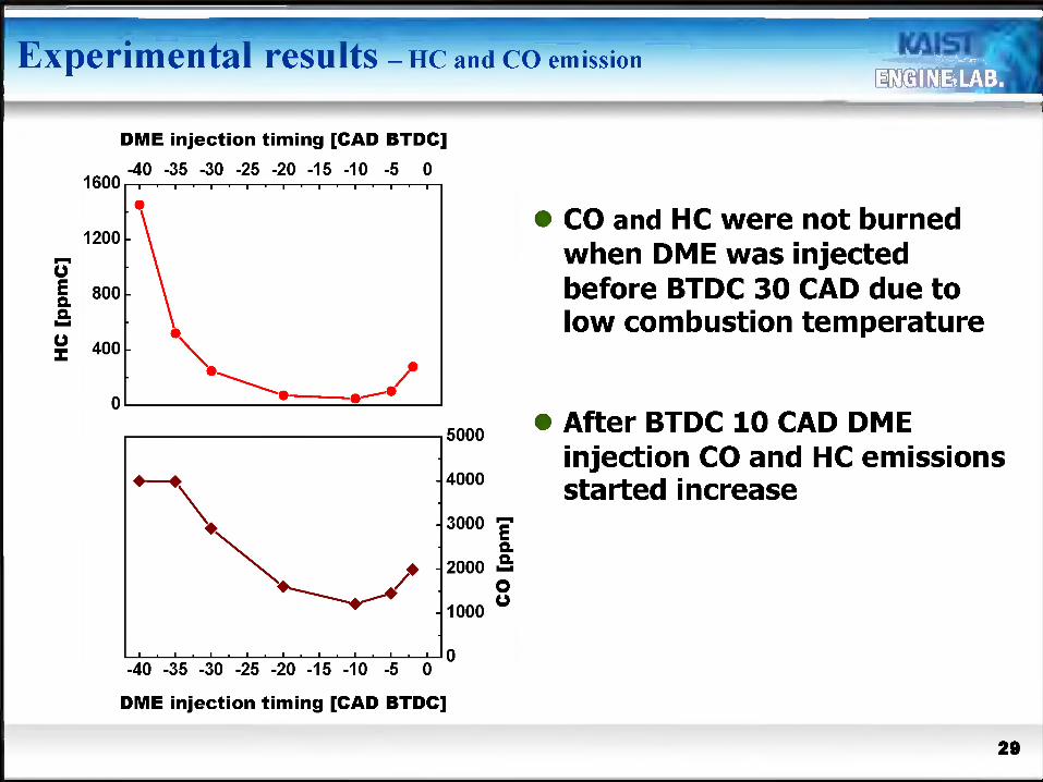
DME injection timing [CAD BTDC]-40 -35 -30 -25 -20 -15 -10 -5 0
1200 -
- 4000
- 3000 T
♦ - 2000 >=
- 1000
-40 -35 -30 -25 -20 -15 -10 -5 0
DME injection timing [CAD BTDC]
• CO and HC were not burned when DME was injected before BTDC 30 CAD due to low combustion temperature
• After BTDC 10 CAD DME injection CO and HC emissions started increase
29
Exper
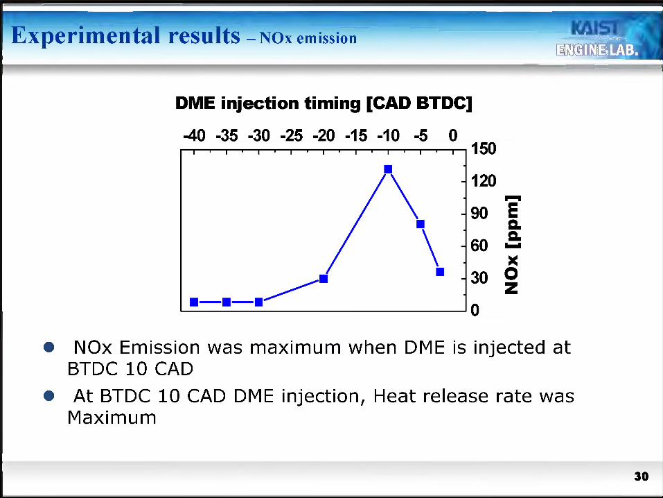
DME injection timing [CAD BTDC]
■40 -35 -30 -25 -20 -15 -10 -5 0
- 90 E
• NOx Emission was maximum when DME is injected at BTDC 10 CAD
• At BTDC 10 CAD DME injection, Heat release rate was Maximum
30
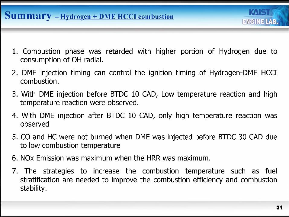
1. Combustion phase was retarded with higher portion of Hydrogen due to consumption of OH radial.
2. DME injection timing can control the ignition timing of Hydrogen-DME HCCI combustion.
3. With DME injection before BTDC 10 CAD, Low temperature reaction and high temperature reaction were observed.
4. With DME injection after BTDC 10 CAD, only high temperature reaction was observed
5. CO and HC were not burned when DME was injected before BTDC 30 CAD due to low combustion temperature
6. NOx Emission was maximum when the HRR was maximum.
7. The strategies to increase the combustion temperature such as fuel stratification are needed to improve the combustion efficiency and combustion stability.
31
Summary
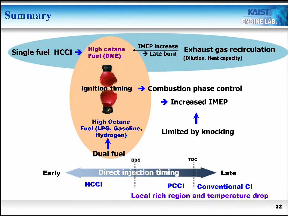
Single fuel HCCI High cetane „ IMEPincrease gy^aust gas recirculation
Early
Fuel (DME) Late burn(Dilution, Heat capacity)
£Ignition liming
vCombustion phase control
» Increased IMEP
High Octane Fuel (LPG, Gasoline,
Hydrogen)
Dual fuelBDC
tLimited by knocking
TDC
Direct injHtion timingHCCI PCCI
Late
Conventional ClLocal rich region and temperature drop

UDoarote ^®oo8