Case 5:07-cr-00063-gec-jgw Document 317 Filed 05/15/2008 ...
WBS: 12.23QA: L
MOL. 19980622.0079
Civlian Radioactive Waste Management SystemManagement & Operating Contractor
Summary Report of Commercial Reactor Criticality Datafor McGuire Unit I
Revision 01
Document Identifier No.- BODOOOOGD-01717-5705S.00063 REV 01
Aprl 13, 1998
PrEpmrd for.
U.S.DqpartmentofE uyYucca MooWn Site Cac on Project Office
P.O. Box 30307Las Vegas, NV 89036-0307
Prqpmrcdb.
Cii Radioactive Waste m t Systemagement & Operating Contractor
180 TownCenterDriveLas V-as, Nevada 89134
Under Conract NumberDE-ACOS.91RW00134

Cvilian Radioactive Waste Management SystemManagement & Operating Contractor
Summary Report of Commercial Reactor Criticality Datafor McGuire Unit 1
Document Identifier No.: B00000000-01717-570500063 REV 01
April 13,1998
I
I
IPeprd by.:
Checked by
ClW. may, '*Neutronics Methodology
K D. WdA CheccrNeutronics Methodology
L B. Wimer, Checker (Refece 5 Input)Neuhrnics Meffiodology
I
Date: 4/Z5 .
Date: ________
Date: c/ S-'
Checked by:
I
Date: ). , 9 8I Aved
I BOOOOOo01717 C705S0063 REV 01 a APrll 1 1998

ISMTORY OF CHANGE PAGE
Initial Issuance, REV 00 _ . . . ...... ............. .. .. _... .b..August 15, 1997
|Update, REV ... .... . ..... ~...... . . . .. Apri 13, 1998
I New data added. Changes wr maremd with change bars in the left margin or as otherwisenoted (Figures 3-1 through 3-15, Tables 3-3 and 3-4).
I BOOOOOO0O-01717-670-5-0063 REV GI Ml pi 2,19April 13, 1998
Acknowledgments
The author (Prepar) would liMe to express his thanks to Duke Power Company for theirassistance with gathering and verification offthe nformation used to model the critical pointconditions for the McGuire Unit 1 reactor. The author would also like to thank Duke PowerCompany for ganting permsion to pubish this information.
I BOOOOOOO41717-S70500063 REV 01 IV April 13, 1998

TABLE OF CONTENTS
I
Section
1.0 IN.RODU .............1 Background........ . ............................. ................... ..1.2 Objectv ....... .1.3 Scope . ... . . . .1A4 Quality Assurne .... . ... ...
2.0 REACIlOR DESIGN INFOR1MAv.ION ..... ..........
3.0 FJEIL CYCLE DESIGN IFORMAI...ON. ........... .3.1 Fuel Batch Data .............. _.3.2 Fuel Assenbly Data........ .*.........*..........
4.0 CORE OPERATIONS AND STATEPOINT INFORMATION.4.1 Core Follow Datta............. .....................................4.2 Statepoint Critical Condition Meases....................
5.0 CONCLUSIONS...- . . . . . ................. . ... ......
6.0 REFERENCES ... .*.*..............
......... n.................. ..............-
I.. . ......._... I
I..................................... ..... . a..&
..................... . ................. .1
.......... .... ................... _3.
Page
I
~~~~.. ................ ...- @@@-......**36,36'2
A.. ................. @ *
....... . ... ...... . ...-..... ... ...... .... auC
.............................. ..aS,..581nM
.......... .. . .. ........... . ....... .I*
......................------------- XVZ
........ 104
............. h
I BOOOOOOO01717.5705-O0 REV 01 AprH 13, 199SBy
I-UST OF FIGURES
Figure Page
2-1.2-2.2-3.2-4.2-5.2-6.2-7.2-8.2-9.2-10.2-11.2-12.2-13.2-14.2-15.2-16.2-17.
2-18.2-19.2-20.3-1.3-2.3-3.3-4.3-5.3-6.3-7.348.3-9.3-10.3-11.3-12.3-13.3-14.3.15.
Horizontal View of Vessel Inernals Along Core _Radial View of Fuel Assimbly Layout Along the Co Flat ............ .... ...... .................. 6Radial View of a Single 17 x 17 STI) or OFA Fuel Assembly 9 ......................... 9Radial View of a Single 17 x 17 MKBW Fuel Assembly .. ...........
Axial Dimensions by Region for 17 x 17 STD Fuel Assembly 1..... ..............
Axial Dimensions by Region for 17 x 17 OFA Fuel Assembly .....-.. .12
Axial Dimensions by Region for 17 x 17 MIMW Fuel Assembly ................. ............. 13Axial Dimensions for Guide TUbes for SID Fuel Assembly ..................... ...... -I1Istzuent Tube Axial Dimensions for SID Fuel Assembly ..................... ... ........ 19Fuel Rod Assembly Axial Dimensions for STD Fuel Assembly ........ ...... ............... .... 20Axial Dimensions for Guide Tlubes for OFA Fuel Assembly ..............................._21Insiz=et Tube Axial Dimensions for OFA Fuel Assenibly ..................... .... . .Fuel Rod Assembly Axial Dimensions for OFA Fuel Assembly ....... ......................... 23Axial Dimensions for Guide Tubes for MOKBW Fuel Assembly ........... ........................... 24
Jinstrument Tue Axial Dimensions for MfW Fuel Assembly ... ............. 25Fuel Rod Assembly Axial Dimensions for MKBW Fuel Assembly ................. 26Axial Dimensions for RCCAs (Rods 0%/ Withdrawn) for STD, OFA, and MKBW
Fuel Assemblies ............ . . . _ 29Axial Dimensions for Pyrex BPRAs for STD, OFA, and MKBW Fuel Assemblies ......32Axial Dimensions for WABA BPRAs for STD, OFA, and MKBW Fuel Assemblies ... 33Axial Dimensons for Thimble Plg for SID, OFA, and MKBW Fuel Assemblies ........ 34Cycle I One-Eighth Core Loading for McGuire Unit I ..............
Cycle 2 One-Eighth Core Loading for McGuire Unit 1 . ................................. A1Cycle 3 One-Eighth Core Loading for McGuire Unit I .................... 42Cycle 4 One-Eighth Core Loading for McGuire Unit I . .. ......................... 43Cycle 5 One-Eighth Core Loading for McGuire Unit I ............................. . ...... 44C(ycle 6 One-Eighth Core Loadi-g for Mc}uire UIoit 1 ............................... . .. ASCycle 7 One-Eigh Core Loading for McGuire Unit 1 .........Burnable Poison Rod Locations within a Fuel Assembly ..... .... ................. ............ 47Cycle 1 Fuel Assembly Identification & Locations for McGuire 1 ................Cycle 2 Fuel Assembly Identification & Locations for McGuire I ................. ..... A9Cycle 3 Fuel Assembly Identification & Locations for McGuire I .................. 50Cycle 4 Fuel Assembly Identification & Locations for McGuire 1 . ..................... 51Cycle S Fuel Assembly Idenicaion& Locations for McGuire 1 ..... ....... 52Cycle 6 Fuel Assembly Idefi & Locations for McGuire 1 .......... ............ . 53Cycle 7 Fuel Assembly Identification & Locations for McGuire 1...................................54
I Bw0000 1717-S70S.00063REV01 vi April 13,1998
LIST OF TABLES
Table Page
2-1. Dimensions fim Core Center to Outside Surfice of Prssurc Vessel .............................. 32-2. McGuire 1 Fuel AssemblylCore Data .. .... .....................2-3. Volume Fractions for Non-Fuel RPeons for Non-Control Assemblies (7) ... 142-4. SID Fuel Rod Assembly Volume Fractions for Regions 3 and 5 ........ 152-5. Volume Fractions for Non-Fuel Regions for Non-Control Assemblies (OFA) ............... 152-6. OFA Fuel Rod Assembly Volume Fractions for Regions 2, 3, and S ............... .. 162-7. Volume Fractions for Non-Fuel Regions for Non-Control Assemblies (MKBW) ..... 162-8. MKW Fuel Rod Asembly Volume Fractions for Rgions2, 3, and 5 ................... .... 172-9. Volume Fractions for SI Assemblies vit RCCAs (0%O Withdrawn) for
Regions 1-3 ).............. ~ 272-10. Volume Fractions for OFA Assemblies with RCCAs (0% WVithdrawn) for
Regions 1-3 ....... .... .. ....2-10a. Vohlme Fractions for MKBW Assemblies with RCCAs (0%/O Withawn) for
Regions 1-3 ---------......... 282-11. Volume Fractions for STD Fuel Assemblies with WABA or Pyrex BPRAs for
Regions 2 - 3 ...... . .3.......................................... ........................ ..312-12. Volume Fractions for OFA Fuel Assemblies with WABA or Pyrex BPRAs for
Regions 2 - 3 .......... _. . . . 312-13. Volume Fractions for MBW Fuel Assemblies with WABA or Pyrex BPRAs for
Regions 2 - 3 ................. 313-1. Fuel AsseniblylnlCycle Description for Cycles 1-7 ....... ..... 373-2. Cycle Length and rime During Cycle Statepoint Data Measured for Cycles 1-7 383-3. Fuel Assembly Locations by Cycle for Burrup Calculations . ..................... 5634. Control Rod and BA Loadings by Cycle for Brnup Calculations ................ ................ 574-1. Axial Node Spacigs for Mc~uire I Burnup Calc...ions .................. .. 594-2. Burnup and TR Feedback Parameters by Axial Node for Assembly B25b .............. ;._.604-3. Bunup and TR Feedback Parameters by Axial Node for Assembly B3la .................... 614-4. Burnup and TH Feedback Parameters by Axial Node for Assembly C25.........................624-5. Bumup and TH Feedback Parameters by Axial Node for Assembly DS .....4-6. Burnup and TH Feedback Parameters by Axial Node for Assembly D14 . . . 654-7. Buroup and TH Feedback Parameters by Axial Node for Assembly D14a ............ ....... 664-8. Burnup and TH Feedback Parameters by Axidal Node for Assembly D17a ....................... 674-9. Burmup and TH Feedback Parameters by Axial Node for Assembly D21 ...... 684-10. Burnup and TB Feedback Parameters by Axial Node for Assembly D25 ......... ............. 694-11. Bumup and TR Feedback Parameters by Axial Node for Assembly D28 ....... .704-12. Burnup and TH Feedback Paameters by Axial Node for Assembly E2 .......... ....714-13. Burnp and TB Feedback Parameters by Axial N.ode for Assembly 8...........................724-14. Burnup and TB Feedback Parameters by Axial Node for Assembly EIO . .......... 734-15. Bumup and TH Feedback Parameters by Axial Node for Assembly E12 . ..... 744-16. Bunmup and TH Feedb Pa eters by Axial Node for Assembly E12a . 7.5........... ..... 754-17. Bumip and TH Feedback Parameters by Axial Node for Assembly E14........ ............ 764-18. Burnup and TH Feedbac Parameters by Axial Node for Assembly E14a ....... 77
I BOODOOOOO-1717-570.50006 REV ClT Arl1319TH . AprU 13,199S

LIST OF TABLES (Contd)
Table Page
4-19. Bumup and TH Fcedback Parameters by Axial Node for Assembly E17 ... . ............. . ..... 784-20. Burmip and TH Feedback Parameters by Axial Node for Assembly E17a ....................... 794-21. Bumup and TH Feedback Parameters by Axial Node for Assembly E21 ......... ............ .. so4-22. Burnup and TH Feedback Parameters by Axial Node for Assembly E23 . . 804-23. Burnup and TH Feedback Parameters by Axial Node for Assembly E25 ....... 814-24. Burnup and TH Feedback Parameters by Axial Node for Assembly E28 .............. 824-25. Bumup and TB Feedback Parameters by Axial Node for Assembly F2 .......... .. . ............ 834-26. Bumup and TH Feedback Parameters by Axial Node for Assembly F4 ....... 844-27. Bumup and TH Feedback Pareters by Axial Node for Assembly F8 ............ ...... . 54-28. Burnmp and TH Feedback.Parameters by Axial Nodefor Assembly F12 .. .......... 864-29. Burnup and TH Feedback Parameters by Axial Node for Assembly F14 ...... 874-30. Burnup and TB Feedback Pametes by Axial Node for Assembly F17 ..... . ............... 884-31. Burmup and TB Feedback Parameters by Axial Node for Assembly F19 .... ......... .. 94-32. Burnup and TH Feedback Parameters by Axial Node for Assembly F21 ....................... 904-33. Burnup and TB Feedback Parameters by Axial Node for Assembly F23 ..... .91
4-34. Burnup and TH Feedback Pameters by Axial Node for Assembly F25 ..-... ................ 924-35. Bumnup and TH Feedback Parameters by Axial Node for Assembly F28 ..934-36. Burnup and TH Feedback Parameters by Axial Node for Assembly G2 ... .................. 944-37. Bumup and TH Feedback Parameters by Axial Node for Assembly G4 .......... ........... 944-38. Burnup and TB Feedback Parameters by Axial Node for Assembly 08 .......................... 954-39. Burnup and TB Feedback Parameters by Axial Node for Assembly 010 .......... 954-40. Burup and TB Feedback Parameters by Axial Node for Assembly C012 .6
4-41. Burnup and TH Feedback Parameters by Axial Node for Assembly 014 ................ 964-42. Bumup and TH Feedback Parameters by Axial Node for Assembly G17 .................... 974-43. Burnup and TH Feedback Parameters by Axial Node for Assembly G19 .......... 974.44. Burnup and TH Feedback Parameters by Axial Node for Assembly 023 ............... 984-45. Burnup and TH Feedback Parameters by Axial Node for Assembly 05 94-46. Bunup and TH Feedback Parameters by Axial Node for Assebly 028 ....... ..... 994-47. Rod Insertion Time by Axiil Node for Assembly B25b ................. 1004-48. Rod Insertion rime by Axiai Node for Assembly B3 la. ...................... ........... ....... 1004.49. Rod Insertion Tune by Axial Node for Assembly D8 ................................ .... .... 1014-50. Rod Insertion Time by Axial Node for Assembly E14a....................................... 1014-51. Critical Boron Data for McGuire I Burrmp Calculations ........ ................... 1024-S2. Statepoint Data for McGuire Unit 1 - Measured Critical Conditions ....... .... ....... -...1034-53. Statepoint Data for McGuire Unit 1 - Shutdown and Startup Dates................................103
I DOOOOOODO.01717-570S.00063 REV 01 Api 3 9April 13,1998
1.0 INTRODUCIION
The 'Summary Report of Commercial Reactor Criticality Data for McGuire Unit 1 contains thedetailed information necessary to perform commercial reactor criticality (CRC) analyses for theMcGuire Unit 1 reactor.
LI Background
The United States Depatment of Energy (DOE) Offlce of Civilian Radioactive WasteManagement (OCRWI) is developing a methodology for critical anadysis to support diosalof commercial spent nuclear fel in a geologic repository. A topical report on the disposalcriticality anaysis methodology is scheduled to be submitted to the United States NuclearRegulatory Commission (NRC for formal review in October 1998. Tbis sumnmary reportprovides data that will be used in analyses that will support the development of parts of thedisposal criticality analysis methodology.
12 Objecfive
The objective of this report is to present the data required for performing analytical CRCevaluations for the McGuire Unit 1 reactor. Results from the CRC evaluations will support thedevelopment and validation of the neutronics models used for criticality analyses involvingcommercial spent nuclear fueL The models and their validation will be discussed in theDisposal Criticality Anablsis Methodology Topical Report
13 Scope
Ihe scope of this Summary Report is the presentation of data required to perform 6 statepointcalculations from cycles 1, 6 and 7 of McGuire Unit 1. The only interface for the developmentofthe information in this document is with Framatome Cogema Fuels (FCF). FCF is one oftheteammates of the Civilian Radioactive Waste Management Systm Mangementand OperatingContrator (&O). FCF idependently requested and received ion from Duke PowerCompany, the ownpor of McGuire Unit 1, to publish the information related to statepointmeasurements that is recorded in this document All the information contained in this report isdocumented in an FCF calculational file (Reference 5). The data provided in Refece 5 wasobtained from various other reports, calculations, and drawings developed under an NRCaccepted quality assurance program (Re1erence 1) and the data has supported prior liceingsubmittals. The data therefore will be considered acceptable for quality affecting activities andfor use in analyses affecting procurement, construction, or fabrication.
1A Quality Assmrance
The Quaity Assurance (QA) program applies to the deveopment ofthis report The dataprovided in this report will indirectly be used to develop the methodology for evaluating theMonitored Geologic Repository (MGR) waste package and engineered barrier segment TheQAP-2-3 (Classficalon ofPermanent items) evaluation entitled aalflcaflon ofthe
I BI000000-01717-570-00063 REV 01 Api1398I Apri 1,1998
Preliminay MGDS Repository Design (eference 2, TBV-228) has identified the waste packageas an MGR (formerly MODS) item important to safety, waste isolation, and physical protectionof materials. The Waste Package responsible manger has evaluated the technical documentdevelopment activity in accordance with QAP-2-0, Conduct ofActvities. The QAP-2-0 activityevaluation, Develop Tecdnical Documents (ROference 3), has determined that the preparation andreview of this technical document is subject to Qualty Assurance Requirements and Description(Rcfrence 4) ents. As specified in NLP-3-1S, Documentation of QA Controls onDrawings, Speclcatons, Design Analses, and Technical Documents, this activity is subject toQA controls. No scintific and epgineeg g software or c taonal software was used in thedevelopment of this report.
I iO0-OO01717-67OS000 REV Al2 April 13,1998

2.0 REAACTOR DESIGN INFORMATION
This section provides general maferial and geometry data for modeling the McGuire Unit 1reactor. Figures 2-1 through 2-20 provide pictorial representations of various components thatmust be modeled. A horizontal view of the vessel internal is presented in Figure 2-1. Ihisincludes the 193 fuel assemblies (FA) in the reactor core region. AMl dimensions in this figureare measured from the center of the reactor core. A radial view of the fuel assembly layout(along the core flat) and edending through the core liner is provided in Figure 2-2. The corelin, core barrel, neutron pad, and vessel weld liner are represented as stainless steel (SS304from Reference S or A240, Type 304 from 1997 Anal Book qfASTMStandards, Vol. 01.03,Section 1, Iron and Steel Products, p. 37, Table 1). The pressure vessel is carbon steel (CSS08firm Reference S or A508, Grade 2, Class 1 from Am=a Book oqfAS7 tndards, Vol. 01.05,Section 1, Iron and Steel Products, p. 281, Table 1). Table 2-1 provides dimensions from thecenter of the core (along the core fla) to the outside suface of the pressure vessel.
Table 2-L Dimensions f&om Core Center to Outside Surfhce of Pressure Vessel
Thickness (cm) Oater Radius (cm)DpesrltionCore Center% FA-1WterFA-2WaterFA-3WaterFA-4WaterFA-SWaterFA-6WaerFA-7Water*FA-8WaerCore LinerWaerCore BaulWaterVessel IinerPressure Vessel
SMI & OFA
10.701020.10160
21A02040.10160
21.402040.10160
21A02040.10160
21.402040.10160
21.402040.10160
21.402040.10160
21AO2040.213502.85000
23.675.72
25.470.56
1 21.99
MWs
10.699750.10414
21.399500. 104 14
21.399500. 104 14
21.399500. 10414
21.399S00.10414
21.399500.10414
21.399500. 10414
21.399500.214772.8500
23.675.72
25.470.56
21.99
00.0000010.7010210.8026232.2046632.3062653.7083053.8099075.2119475.3135496.7155896.81718
118.21922118.32082139.72286139.82446161.22650161.4416429187.96193.68219.15219.71241.70
-MTBW00.0000010.6997510.8038932.2033932.3075353.7070353.8111775.2106775.3148196.7143196.81845
1182179511832209139.72159139.82573161.22523161.4416429187.96193.68219.15219.71241.70
I23
STD - Wesdnghouse 17 x 17 stndard fiel assemblyOFA - Westinghouse 17 x 17 optimld f&el assembyMEW - Fanatome Cogema Fues Mak-BW 171 17 fued assembly
B0000000 I01717-570S00063 REV 01 3 Aprn 13,1998
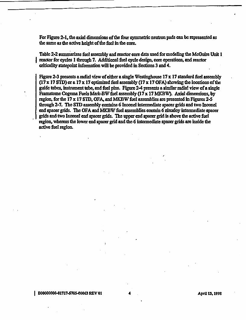
For Figure 2-1, the axial dimensions of the four symmetric neutron pads can be represented asthe same as the active height of the fuel in the core.
Table 2-2 summarizes fuel assembly and reactor core data used for modeling the McGuire Unit Ireactor for cycles 1 through 7. Additional fuel cycle design, or operations, and reactorcriticality statepoint infion will be provided in Sections 3 and 4.
Figue 2-3 presents a radial view of ither a single Westinghouse 17 x 17 standard fuel assembly(17 x 17 STD) or a 17 x 17 optimized fuel assembly (17 x 17 OFA) showin the locations oftheguide tubes, instrument tube, and fuel pins. Figure 2-4 presents a simla radial view of a singleFramaome Cogema Fuels Mark-BW fi assebly (17 x 17 MKBW). Axial dimensions, byregion, for the 17 x 17 STD, OFA, and MKBW fuel assemblies are presented in Figures 2-5through 2-7. The STD assembly contains 6 Inconel intermediate spacer grids and two Inconelend spacer grids. The OFA and MKBW fuel assemblies contain 6 zircaloy intermediate spacergrids and two Inconel end spacer grids. Ihe upper end spacer grid is above the active fuelregion, whereas the lower end spacer grid and the 6 intermediate spacer grids are inside theactive fuel region.
I BOOOOOOOO41717-5700500063 REV 01 4 April M 1998

Figure 241. Horizontal View of Vessel Internals Along Core Mldplane
cge Iner, core bane?, neuronpact &vessel Kner S304
meactorvessel a CWS50
| BOOOD0OO-01717-5705.00063 REV 01 5 April 13, 1998
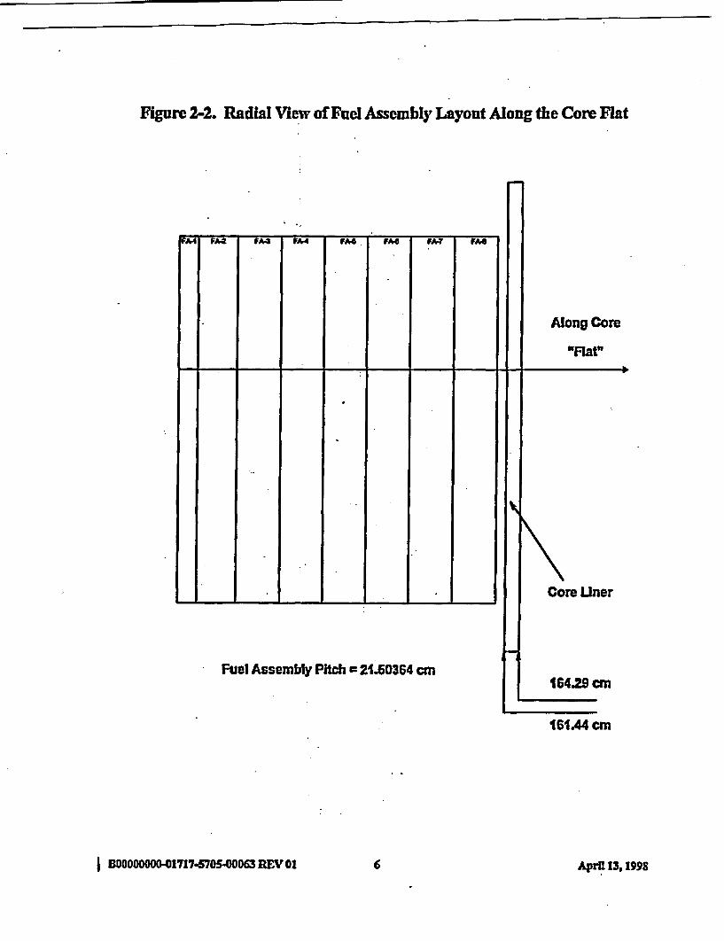
Figure 2-2. Radial View of Fuel Assembly Layout Along the Core Flat
Fuel Assembly Pitch = 21.60364 cm
I BOOOOOOOO-01717.mSX05.0063 REV 01 6 Apri 13,1I998
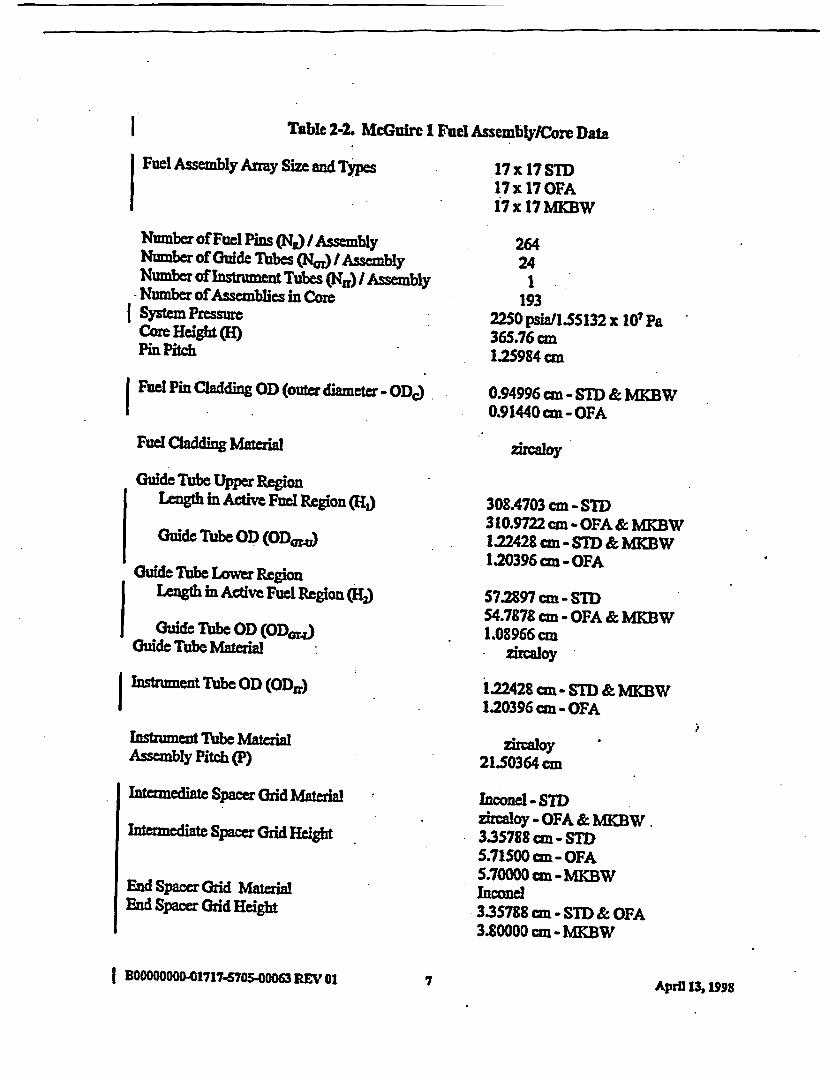
I Table 2-2. McGuire 1 ruel AssemblylCore Data
IFuel Assembly Array Size and Types
Number of Fuel Pins (Nj / AssemblyNumber of Guide Tubes (Ne) I AssemblyNumber of Instmment, Tubes (N.R) Assembly
- Number of Assemblies in CoreI System Pressure
Core Hight(H)Pin Pch
I Fuel Pin Cladding OD (outer diameter - ODc)
Fuel Cladding M ial
Guide Tube Upper RegionLength in Active Fuel Region (H1)
Guide Tube OD (OD=)
Guide Tube Lower RegionLength in Active Fuel Region ,(H)
Guide Tube OD (ODa)Guide Tube Material
17 x 17STD17x 17OFA17x 17MKBW
26424
1193
2250 psiall.55132 x 10 Pa365.76 cm1.25984 cm
0.94996 cm - STD & MKBW0.91440 cm - OFA
zircaloy
308.4703 cm - STI)310.9722 cm - OPA & MKBW1.22428 cm - STD & MKBW1.20396cm - OFA
57.2897 cm - ST)54.7878 cm - OFA & MKBW1.08966 cm
zircaloy
I Instrument Tube OD (ODr)
bstrument Tube MaterialAssembly Pitch (P)
Intrmediate Spacer Grid Material
intenediate Spacer Grid Height
End SpaceriGrd MaterialEnd Spacer Chid Height
1.22428 cm - STD & MKBW1.20396 cm - OFA
21.50364 cm
Inconel - STWzircaloy - OFA & MKBW.3.35788 cm - STI)5.71500 am - OFA5.70000 cm - MKBWInconel335788 cm - STD & OFA3.80000 cm - MKBW
i
I BDOOODOOOO01717170S75.000 REV 01 7 April I3 1998
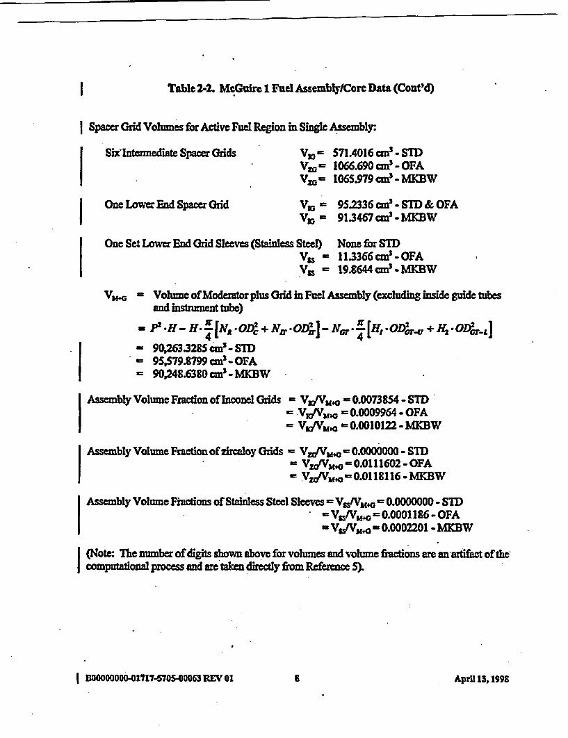
| Table 2-2. McGuire 1 Fuel Assembly/Core Data (Cont'd)
Spacer Grid Vohmes forActive Fuel Region in Single Assembly:
Six Intermediate Spacer Grids V, = 571A016 cm3 - STDVzo 1066.690 cm3 - OFAVz= 1065.979 cm! - MKBW
One Lower End Spacer Grid VY - 95.2336 cma - STD & OFAVl = 91.3467 cm' - MBW
One Set Lower End Grid Sleeves (Stainless Steel) None for SIDVss - 11.3366 cm! - OFAVss - 19.8644 cm - MKBW
V f+G Volune of Moderator plus Grid in Fuel Assembly (excluding inside guide tubesand instrument tube)
P2 *g H -H4 IJr [ARODC' + NtO ,PW] -N *G4 [H. *OPO'G-U + H2 *OP2GT-L= ~~~4
- 90X3.3285 cm'- SDT9S,579.8799 cm5 - OFA90,248.6380 cm! - MKW
Assembly Volume Fraction of Inconel Grids = VmfVuo 0.0073854 - STDVmtVm.G = 0.0009964 - OFAVglVM=a 0.0010122 -MKBW
Assembly Volume Frcdon of zircaloy Grids = Vzr/V = 0.0000000 - STDVz/Vm.o =0.011602 - OFAVzl/Vmo =0.0l18116-MKBW
Assembly Volume Factions of Stainless Steel Sleeves= VOIV. -0.0000000 - SIDV-s/VS+G = 0.000 186 - OFAVufVM.O = 0.0002201 - MKBW
I (Note: The number of digits shown above for volumes and volume fractions are an artifict of thecomnputaional process and are takn directly fiom Reference 5)
I BOOOOOOOO-0o1m716705-00063 REV 01 a Apral 13, 1998

I Figure 2-3. Radial View of a Single 17 1 17 STD or OFA Fuel Assembly
W -Assembly Pitch a 21.60364 c.I I
I Jac- Assembly Outer DImenslons = 21tA0204 cm-$ I
I.
I I I I I I I I I -I I I I I I I 7
I I I 1i I L l 1 1 111 MT I l Fl 1 T l l B l I1 I T T I I Tll I I T _ _ I
_ _ i _ _ @ _ _ s _ _ i _ ,_< _ _ _ _ _ __
_ _ I_ _ _ _ _ _ _ _ _ _ _ _ __ _ i _ _ E _ _ i _ _ E _ _ i _ __ _ _ _ < _ _ _ _ _ _ _ _
_ _ _ _ _ _ _ _ _ _ _ _ _ _ _ _ __ _ i _ _ E _ _ Gi _ _ si _ _ i _ _
__ _ E --- ------Ei- --_ _ _ _ _ Gi _ _ Gi _ _ E _ _ _ _ _
_ __ _ --- 11 _ _ ______I i
Pin Pitch cl1.25984 cmFuel Pin Cell
Guide Tube
®ff Instrument TubeNote: Assembly outer dimension Is less than 17 timesthe pin pitch. The outermost cells (except comers) arerectangularand notsquare lice the othercells
| BOOGOODOOO1717-570S-00063 REV 01 9 April 13,1998
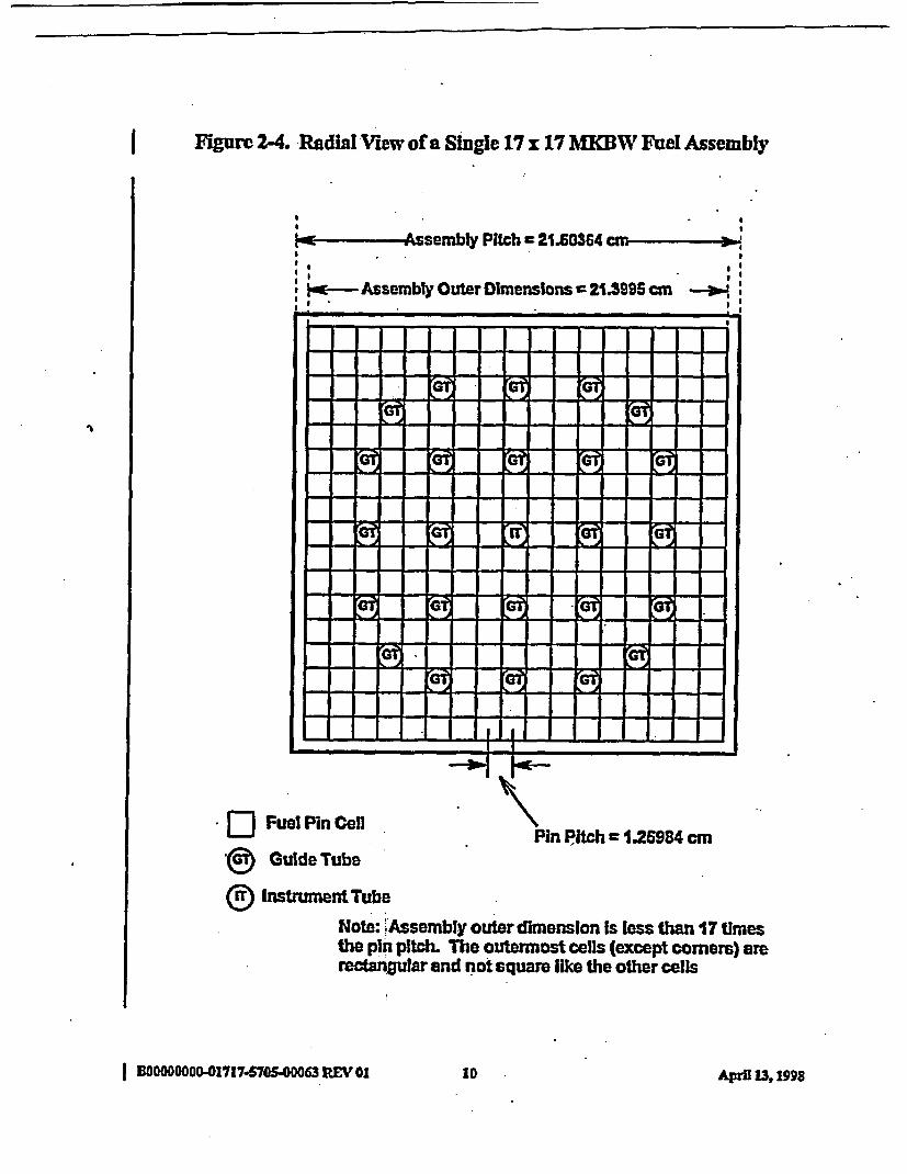
I Figure 2-4. RadIal MVew of a Single 17 x 17 MKBW Fuel Assembly
Jzw Mssembly Pitch = 21.60364 c. -.
II I
* a~~~~~~~~~~~~~~~~~~~~~
Ie- Assembly OuterDimensions =21.3995 cm -1.4I I .
1.
I_ ~~~~I
- _ -
- _ - ---
-- -- i i -- i__
I_- -! l __- __
tS t____ _ __ __-
i ;
Pin Pitch = 1.26984 cm* ID Fuel Pin Cell
t Guide Tube
(D Instrument TubeNote: Assembly outer dimension Is less than 17 timesthe pin pitch. The outermost cells (except corners) arerectangular and not square like the other cells
I 100000000"01717-570S00063 REV 01 10 April 13,199S
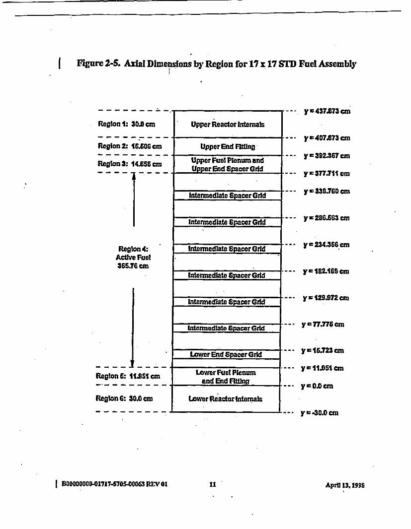
I Figure 2-S. Axal Dimensions by Region for 17 x 17 STD Fuel Assembly
Regbon 1: 30.0 cm
Region 2: 1606 acm
Region 3: 14.656cm
Region 4:Active Fuel365.76 cm
Region 6: 1 t51 cm
Region 6: 30.0 cm
Upper Reactor Internals
Upper End Fiing
Upper Fuel Plenum andUpper End Spacer Grid
Intermediate Spacer Grid
Intermediate Spacer Grid
Intermediate Spacer Grid
Intermedlatz Spacer Grid .
Intermediate Spacer Grid
Wermeate S:pacer Grid .
Lower End Spacer Grid
Lower Fuel Plenumand End FitLng
Lower Reactor Internals
y = 437.873 cm
y = 407.873 cm
y 392*367 cm
y 377.711 cm
y338.760cm
y 286.663 cm
y c 234.366 cm
y 182. 69 cm
y = 129.972 ca
y = 77.776 cm
y = 15.723 cm
y = I1.951 cm
yOC.0cm
y 0.0cm
I BOOOOO04-1717-5S705WO063 REV O0 it April 13,1998

I Figure 2-6. Axial Dimensions by Region for 17 x 17 OFA Fuel Assembly
Region 1: 30.0 cm
Region 2 15606 cm
Region 3: 14.656 cm
Region 4:ActIve Fuel365.76 cm
Region6: 11*51 cm
Regton 6: 30.0 cm
. -
Upper Reactor Internals
.
9.
UpperEnd Fitting
. Upper huel Plenum and ._.Upper End Spacer Grid
Intermediate Spacer Grid
Intermedlate Spacer Gri
Intermediate Spacer Grild
Intemlediate Spacer Grld
Intermediate Spacer Grid
Intermedate SpacerGrd _
Lower End Spacer Grid
Lower Fuel Plenumand End Filting
Lower Reactor Internmas
yc437.873 cm
y e 407.3 cm
Y 392.367 cm
ya377.711 cm
y c 339.928 an
ys287.731 m
y - 23.63 an
y a 183M7 cm
y o 131.140 an
y c 7843 cm
y 1L723 cm
ry11is1 cm
y0G.OCm
y 4-0.0 cm
I BOOOOOOO-01717-S705-00063 REV 2i12 April 13, I"S
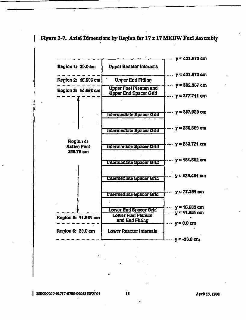
I Figure 2-7. Axial Dimensions by Region for 17 x 17 MKBW Fuel Assembly
RegIon 1: 30.0 cm
Region 2: 16.606 cm
RegIon 3: 14.656 cm
Region 4:Active Fuel365.76 cm
Region 6: 11.951 cm
Region 6: 30.0 cm
Upper Reactor Internals
Upper End Fitting
Upper Fuel Plenum andUpper End Spacer Grid
Intermediate Spacer Grid
Intermediate Spacer Grid
Intermediate Spacer Grld .
Intermediate Spacer Grid
Intermediate Spacer Grid
Intermediate Spacer Grid
Lower End Spacer GrdLower Fuel Plenum
and End Fitting
Lower Reactor Internals
y a 437.873 cm
y c 407.873 cm
y 392.367 cm
y 377.711 cm
y * 337.980 cm
y = 285.869 cm
y = 233.721 cm
y = 181.S2 cm
y = 12A461 cm
y 77.351 cm
y - 16.683 cmy 1 t1.951 cm
y 0.Ocm
y.3o.0 cm
I BO000001717-570S 00063 REV 01 13 Apri 13, 1998
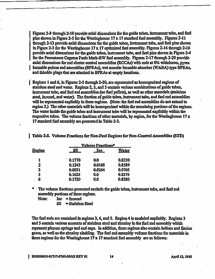
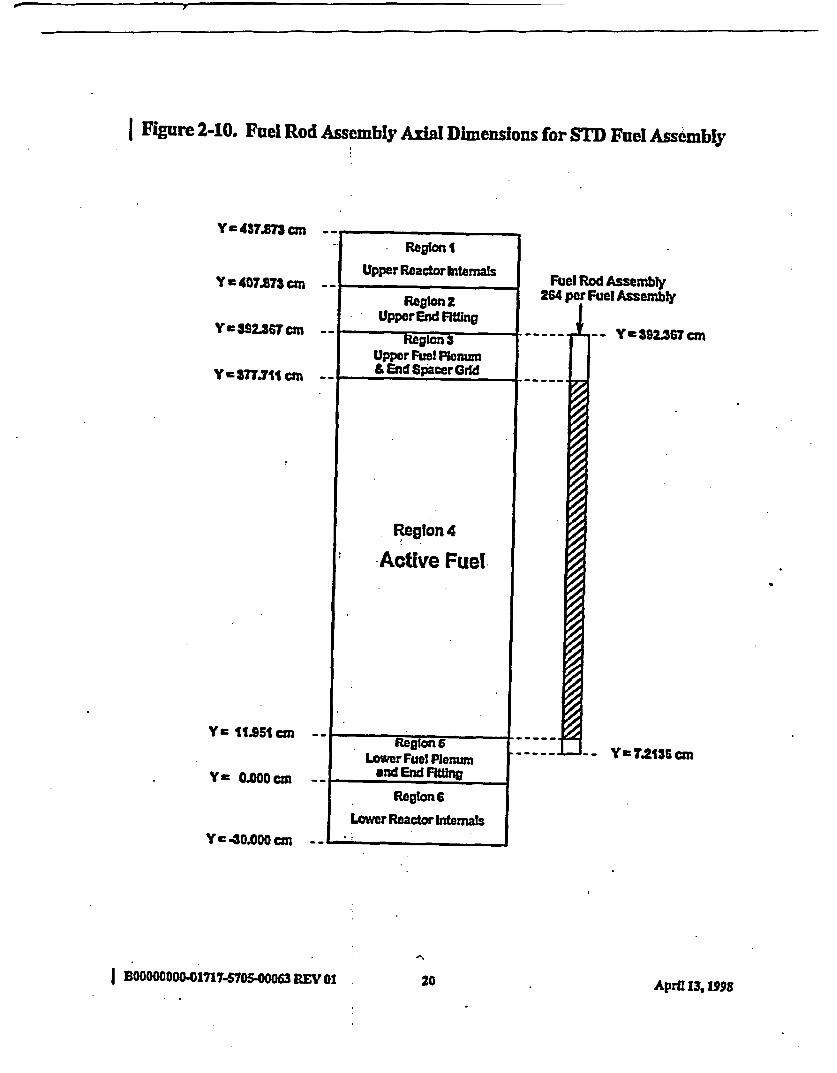
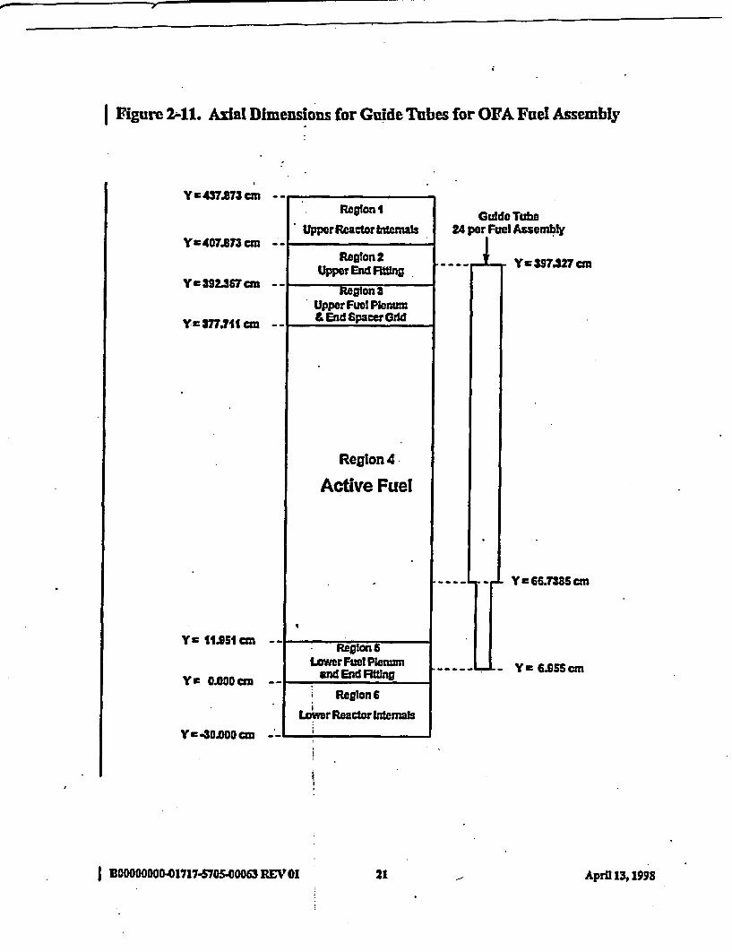
Figures 2-8 through 2-10 provide xial dimensions for the guide tubes, Instrument tube, and fuelpins shown in Figure 2-3 for the Westinghouse 17 x 17 standard fuel assembly. Figures 2-11through 2-13 proside axial dimensions for the guide tubes, instrument tube, and fuel pins shownin Figure 2-3 for the Westinghouse 17x 17 optimized fuel assembly. Figures 2-14 through 2-16provide axial dimensions for the guide tubes, instrument ub, and fuel pins shown in Figure 2-4for the Ftamatome Cogema Fuels Mak-BW fuel assembly. Figures 2-17 through 2-20 provideaxial dimensions for rod cluster control assemblies (RCCAs) with rods at 0%/c withdrawn, pyrexburnable poison rod assemblies (BPRAs), wet annulr burnable absorber (WABA) type BPRAs,and thimble plugs that are attached to BPRAs at empty locations.
Regions I and 6, in Figures 2-5 throuh 2-20, are represented as homogeniz regions ofstainless steel and water. Regions 2, 3, and 5 contain various combinatons oguide tubes,instrument tube, and fuld rod assemblies (no fiel pellets), as well as other materials (stainlesssteel, Inconel, and water). The fraction of guide tubes, intrument tube, and fuel rod assemblieswill be represented explicitly in tese regions. (ote: the fuel rod assemblies do not extend toregion 2.) The other materials will be homogenized within the remaining porions of the regions.The water inside the guide tubes and instrument tube will be represented explicitly within therespective tubes. The volume fractions of der materials, by region, for the Westinghouse 17 x17 standard fuel assembly are presented in Table 2-3.
Table 2-3. Volume Fractions for Non-Fuel Regions for Non-Control Assemblies (STD)
Volume Fraetions*Rep-ion S Inc Water
I 0.1770 0.0 0.82302 0.1243 0.0168 0.85893 0.0031 0.0264 0.97055 0.1625 0.0 0.83756 0.1720 0.0 0.8280
The volume fractions presented exclude the guide tubes, instrument tue, and fuel rodassembly portions of these regions.Note: Inc -Inconel
SS = Stainless Steel
he fuel rods are contained in regions 3,4, and 5. Region 4 is modeled explicitly. Regions 3and 5 contain various amounts of stainless steel and zircaloy in the fuel rod assembly whichrepresent plenum springs and end caps. In addition, these remons also contain helium and fissiongases, as well as the zircaloy cladding. The fdel rod assembly volume fractions for materials inthese regions for the Westinghouse 17 x 17 standard fuel assembly are as follows:
0 BOOOOOOD-01717-5705-00063 REV 01 14 Apral 13, 1998

I Table 2-4. STD Fuel Rod Assembly Volume Fractions for Regions 3 and S
R-edon
3S
Fuel Rod Assemblk Volume Fractions_ SSt - . Zr Cadding! Gs
0.07640.1241
0.05130.1685
0.21730.1898
0.65500.5176
* The eircaloy (Zr)claddingextends fromY-278 cmtoY 391.615 cm. Forall 264 rods,13.904 cm length of fuel cladding is included in region 3 and 3.673 cm length of fielcladding is included in region 5.
The vohume fiactions of other mate: by region, for thie Wesighue 17 s 17 opffiize~d fuxelassembly are presented in Table 2-5.
Table 2-6. Volume Fractions for Non-Fuel Regions for Non-Control Assemblies (OFA)
Volume Fractions*-kne .ReWon
123S6
0.17700.13030.00300.14390.1720
0.00.01780.02490.00.0
0.00.00510.00.01370.0
Water
0.8230.8469
0.97210.84240.8280
* Ihe volume fiactions presented exclude the guide tubes, instrusmt tube, and fuel rodassembly portions ofthese regions.
Ihe fuel rods are contained in regions 2,3,4, and 5. RBgion 4 is modeled cxplicitly. Regions 2,3, and 5 contain various amounts of stainess steel and itaoy in the fuel rod assembly whichrepresents Plenm springs and end caps. In addition, these regions also contain helium andfission gases, as well as the zircaloy cladding. Ihe fiel rod assembly volume fiacdons formaterials in these regions for the Westinghouse 17 x 17 optimized fuel assembly are presnted inTable 2-6.
I BOOOOOOOO.01717-70S40063 REV 01 1S Apri 13,1998

I Table 2.6 OFA Fuel Rod Assembly Volume Fractions for Regions 2,3, and 5
Fuel Rod Assembly Volume FractionsBeioSSr Cladding* Gas
2 0.0703 0.4268 0.1720 033093 0.1342 0.0 0.2344 0.63145 - Solid (diameter - 0.9144 cm) -
T hezircoy claddingexts fiomY 113157cmtoY=394.2309 cm. Foral264rods, the 0.524 cm length of cladding is included in region 2,14.656 cm in region 3, and0.635 cm length is included in region 5.' Region 5 may be modeled as a solid zircaloy rod of1.748 cm length and 0.9144 cm diameter.
I The volume fractions of other materials, by region, for the Ma-BEW 17x 17 fuel assembly arepresented in Table 2-7.
Table 2-7. Volume Fractions for Non-Fuel Regions for NonControl Assemblies (M W)
Volume Fractions*BegiDS Inc _ WaerZeion -j. Su. .s_.
1 0.1770 0.0 0.0 0.82302 0.1040 0.0210 0.0090 0.86603 0.0058 0.0247 0.0 0.96955 0.1417 0.0 0.0059 0.85246 0.1720 0.0 0.0 0.8280
The volume ti presented exclude the guide tubes, instrument tube, and fuel rodassembly portions of these regons.
The fuel rods are contained in regions 3,4. and 5. Region 4 is modeled explicitly. Regions 3and 5 contain various amounts of stainless steel and zicaloy in the fuel rod assembly whichrqpesents plenum spings and end caps. In addition, these regions also contain helium andfission gases, as well as zircaloy cladding. The fuel rod assembly volume fractions for materialsin these regions for the Mark-BW 17 x 17 fiel assembly re presented in Table 2-4.
I BWOOOOO17I7-1SOS-00063.REV Cl1 Arl131916 Apra M 1"S

I Table 2-X MBW Fuel Rod Assembly Volume Fractions for Regions 2,3, and S
Fuel Rod Assemblk Volume FactionsR&ejon la - Zr c daine Gas-
3 0.0779 0.0523 0.2307 0.63915 0.1256 0.1705 0.2040 0.4999
Ihe zircaloy cladding extends from Y = 8278 cm to Y 391.340 cm. For a11 264rods, the 13.629 cm length of cladding Is included in region 3, and 3.673 cm length isincluded in region 5.
1 Boo000000-01717-5705-00063 REV 01 17 April 13� 1998

IFigure 2W. Axial DImensions for Guide Tubes for STD Fuel Assembly
Y-437.873 cm
Y.407A73 cm
Y = 392.367 cm
Yz 377.711 cn
Y 11C.51cm
Yc C.CODan
Y-a30.Ocm -
- -r - -
Region I
Upper Reactor Intemals_ _I_
Reglon 2Upper End Fgang
Guide Tube24 per Fuel Assembly
-Y3989.38m
_--_ .
Keglon 3Upper Fuel Planum& End Spacer Grd
_-_r
Region 4
Active Fuel
_ _ -_1- Y 9S2tcnM n
__-- _ - Y IC "Sscm
I
_--V_ .Region 6
Lower Fuel Plenumand End FWin
-r -
Region 6
Lower Reactor interas
I
I BOOOOO1717S701S00 06 REV 01 Ais APrfI 13, 1998

I 7igure 2-9. Instrument Tube Axial Dimensions for STD Fuel Assembly
Y =437.A73 cn
Y =407.87 cm
Y c392.367 an
Y c377.711 cm
Y = 11.051cmn
Y C 0.000cmn
Yc .30.000cm
* Regon 1
Upper Reactor Internals
Region 2Upper End Ming
Region 3Upper Fuel Plenwn&EndSpacerGrld
Reglon 4
Active Fuel
Reglon 6Lower Fuel Plenum
and End Rfilng
RegionS
Lower Reactor Internas
Instrument TubeI per Fuel Assembly
_ j- - Y a 3TAST an
-- Ye 6.C54canI
I BDOODOCOOO-01717.57054O0D63 REV 0119Arl398 19 Aprf 13,1I§98
0. ~~~7-
I Figure 2-10. Fuel Rod Assembly AxWa Dimensions for STD Fuel Assembly
Y = 437.87 cm
Y = 407.83 cm
Y a392.36T cm
Y -37T.711 an
Y 11.951 cm
Y= a.0cmDa
Y c4ODO0 cm
1 Reon I
Upper Reactor Intemnals
Region 2Upper End FtaTng
Fuel Rod Assembly264 per Fuel Assembly
I _A_
_ ~~Region 3 ._Upper Fuel Plenum& End SpacerGrid -----
- Y 392.SC7 an
. Reglon 4
Active Fuel
- _ X _ _1--
Region 6 -Lower Fuel Plenum
and End RahwY a 7.2136 an
Regon 6
Lower Reactor Internals...
I B00000000-17'17-M750 0063 REV 01 220 April 13, 1998
I Figure 211. Axial Dimensions for Guide Tubes for OFA Fuel Assembly
YEw 437.873 ci
Yc407.673 c
YE 292.367cm
Y c377.7U c=
Ye 11951 cm
Y I 0.800cm=
Yc 30.8000=
Reglon I
Upper Reactor tranalsGuide Tube
24 per Fuel Assemnbly
I_ _l
Reglon 2Upper End PFtng
_ _ I-
Region sUpper Fuel Plenum& End SpacerOldd
Region 4
ActHve Fuel
_ _ ~RegionsLower Fuel Plenm
and End FRing
Y 397.327cm
Y 66.7385 cm
Ye 6955cmI F _
i Region 6Loer Reactor Internals
__-
I BOOODOOOO-1717-5705.00063 REV 01 21 April 131199S.

I Figure 2-12. Instrument Tube Axad Dimensions for OFA Fuel Assembly
I Y*437.873cm ---. -
Y=407.873 cm --
Y a 392.367 a - -
Ya377.71 cm --
ye 1.05=m --
Y e 0.000 cm - -
Region I
UpperReactorlatemals
Region 2Upper End FRtoing
InstrumentTuboI per Fuel Assembly
- - - - Y a 397A44 cm
I. _ .Regiont
Upper Fuel Pen=m& End Spaceradd
._
Region 4
Active Fuel
RegIon 6Lower Fuel Plenum
and End Fitting
Region 6
Ye6654 cm
Lower Reactor Intemals
Yc3.000 cm - -
I BOOWO000-O171757oS700063 REV 01 22 Apra 13,1998
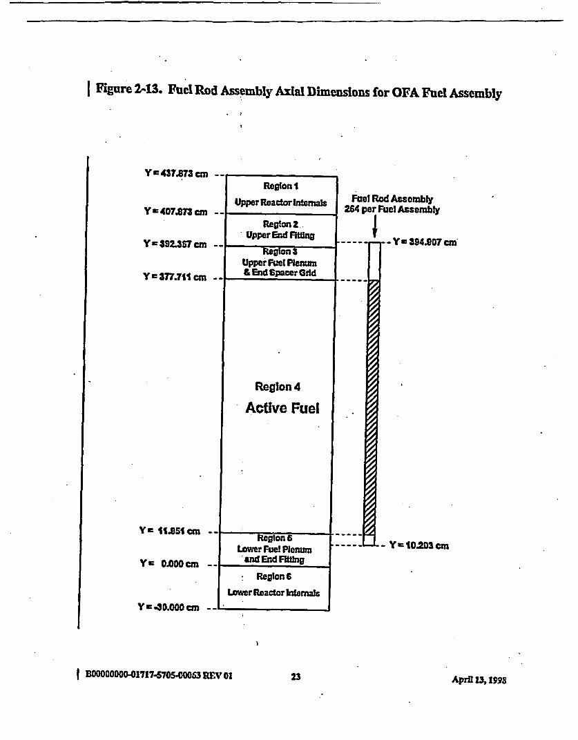
I Figure 2413. Fuel Rod Assembly Axial Dimensions for OFA Fuel Assembly
Y c437.873 cm - ,
Reglon I
Upper Reactor InternasY w4O7.873c
Y a 392.357 cm
Y r-377.711 cm
Y a1I.Sl1cm
Y m 0.000 =
Relon 2 -Upper End FMting
Regton aUpper' Fuzel Penum&EndSpacerGrld
_ _ _ .~~~~~~~~
Fuel Rod Assembly264 per Fuel Assembly
___ _-_ y-Y394.S07 c
- Ye 10203 cm
Region 4
Active Fuel
_ .. _ .
Reston 6Lower Fuel Plenum
and End Fiting_ _
Regson 6
Lower Reactor Inernals
Y4.30.0 cm _-
I BOOOOOOO-017174705.00063 REV 01 23 April 13, IM

Figure 2-14. Axial Dimensions for Guide Tubes for MBW Fuel Assembly
Y c437973 cmn
Y =40.873 cm.
Y c 392.367 an
Y c377.711 cm
Y II.SSIcm
Y 0.000 cm
A,
Regson I
Upper Reactor Intemals_ _ X
Guide Tube24 per Fut Assembly
-- ily- Y 398.99crnRegion 2Upper End FIing
--I_ Reton 3Upper Fuel PlenwnL End SpacerOdd
_ I
Region 4
Active Fuel
- C 66.T3B cm,
-- Y=6.616Cm
I
_ I _ ,
Regton 6Lower Fuel Plenum
nd End FatAX
_
Region 6
Lower ReactorIntaenufs
Y C 4O.O0D cm __
I OOCOOOOOO1717-6005.00063 REV 01 24 April 13,1998
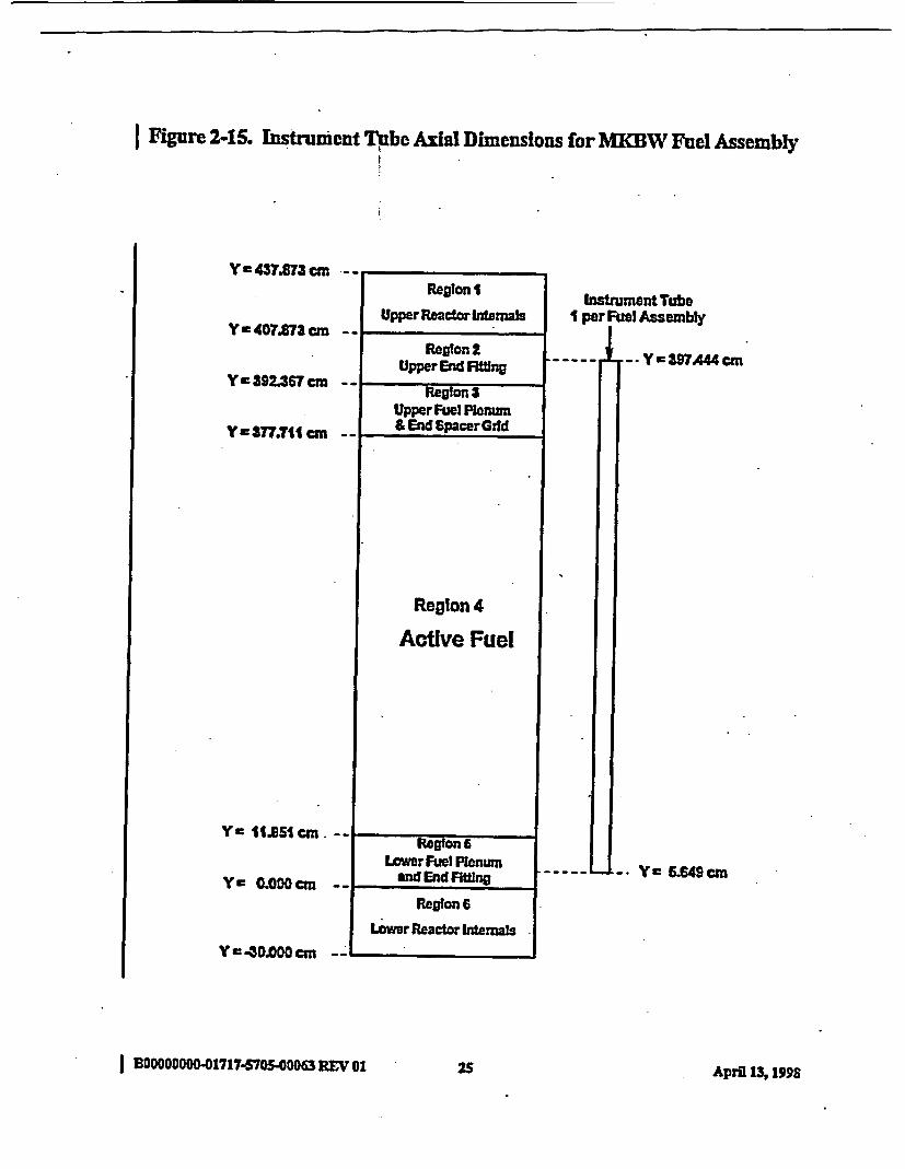
I Figure 2-15. Instrument Tube Axial Dimensions for MKBW Fuel Assembly
I Y a 437.873 cm -- ,Region I
Upper Reactor IntemalsYa4O7.873 cm
Y 392.367 cm
Y=377.71 cm
YC 11.51 cm.
YE 0.000cm
Reagon 2Upper End Mfing
InstrumentTubeI per Fuel Assembly
.__ _ -- Y=39?A44cm
Region 3Upper Fuel Plenum& End SpacerGild
Region 4
Active Fuel
Region 6Lower Fuel Plenum
_ _ eand End FittingI 6.649Y wcm
Region 6
Lower Reactor Internals
YE 40.000 cm _
I DCOOODOO00-01717-57040063 REV 01 i pi 31925 Apru M 1998
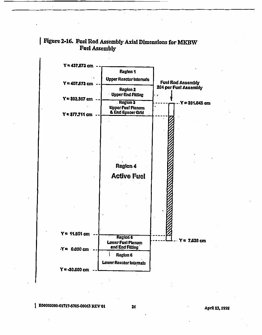
I Figure 2-16. Fuel Rod Assembly Axial Dimensions for MKBWFuel Assembly
Y = 47.873 = -IRegion I
Upper Reactor InternalsY a 407.873 cmn
Y a392.367 an
Y a377.711 cm
Yc 1I.951 an -
*Y m 0.000 cm -
Y r-43.000 an -
-- I
Region 2Upper End Ftg
Fuel Rod Assembly264 per Fuel Assembly
._ I _ -
.Region 3:Upper Fuel Plenum& End SpacerGrld
*1 $,-
Region 4
Active Fuel
.- Y39L848cm
.Y = 7.628 cm-p .
Region aLower Fuel Plenum
and End FiMng.
I Region 6
Lower Reactor Internals
._-
I BDOOOOOON-01717.5705-9- 3 REV 01 26 April L% 1998
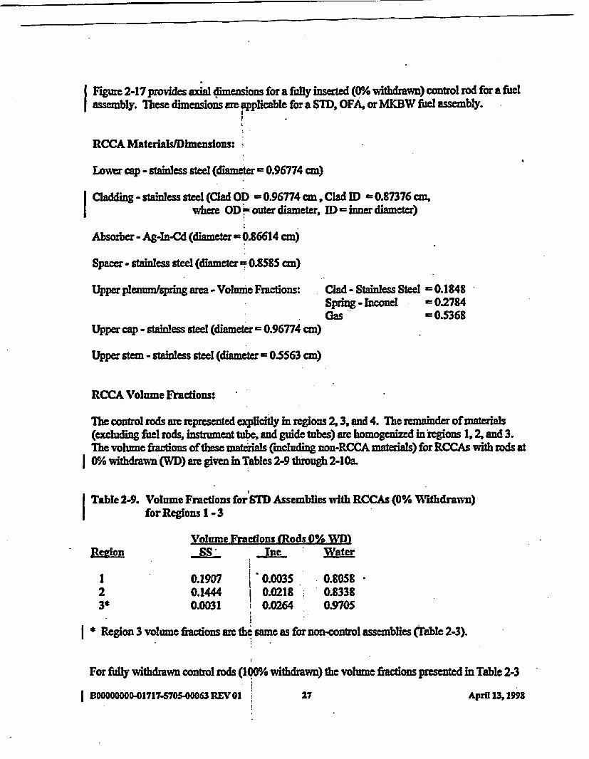
Figure 2-17 povides adal dimensions for a fully inserted (0%h withdrawn) control rod for a fuelassembly. The dimensions ae applicable for a STD, OFA, or MBW fhel assembly.
RCCA Materials/limensions: -
Lower cap - stainless steel (diameter 0.96774 cm)
Cladding - stainless steel (Clad OD = 0.96774 cm, Clad II 0.87376 cm,where OD ! outer diameter, ID inner diameter)
Absorber - Ag-In-Cd (diameter = 0.86614 cm)
Spacer - stainless steel (diameter 0.8585 cm)
Upper plenum/g area - Volume Fractions: Clad - Stainless Steel = 0.1848Spring - Inconel -0.2784Gas =0.5368
Upper cap - stainless steel (diameter = 0.96774 cm)
Upper stem - stainless steel (diameter = 0.5563 cm)
RCCA Volume Fractions:
The control rods are represented explicitly in regions 2, 3, and 4. The remainder of materials(excluding fuel rods, instrument tube, and guide tubes) arc homgenized in regions 1, 2, and 3.The volume fractions of these matedals (including non-RCCA materials) for RCCAs with rods at0% iothdrawn (WD) are given in Tables 2-9 th 2-10a.
Table 2-9. Volume Fractions for SID Assemblies with RCCAs (0% Withdrawn)for Regions 1-3
Volume Fractions (Rods 0% WD}wevlon S Inc Water
I 0.1907 0.0035 0.80582 0.1444 0.0218 0.83383* 0.0031 0.0264 0.9705
Rtgion 3 volume fiacdons are the sameas fornon-conol assemblies (able 2-3).
For fully withdrawn control rods (1Q0% withdrawn) the volume fiactions presented in Table 2-3
BOMOOO"O1717-570S0063 REV01G 27 April 13, 1993

I (for STD non-control assemblies) should be used.
I Table 2-10. Volume Fractions for OFA Assemblies with RCCAs (0% Withdrawn)for Regions 1 -3
I We~onVolume FrActions (Rods 0% WMI)
Inc Zr
123*
0.19070.15160.0030
0.003S0.02320.0249
0.00.00510.0
Mater
0.80580.82010.9721
I * Region 3 volume fractions are the sme as for non-control assemblies (Table 2-).
I
I
For fully widdrawn contro rods (1000% withdrawn) the volume tractions psted in Table 2-5(for OFA non-control asemblies) should be used.
Table 2-10a. Volume Fractions for MKBW Assemblies with RCCAs (0% Withdrawn)for Regions 1 -3
I ReOMVolume Froctions (Rods 0% WID)
SS -nc &Z - Water
I 123*
0.19070.12410.0058
0.00350.0260 '0.0247
0.00.00900.0
0.80580.84090.9695
I * Region 3 volmne fractions are the same as for non-control assemblies (Fable 2-7).
I For fully withdrawn control rods (100% wffidrawn) the volhne fractions presented in Table 2-7(for MWOW non-control assemblies) should be used
I DO0DM OO0-01717-5705-0063 REV 0 8A ril31 9is AprD M 1998

IFgure 2-17. Axial Dimensions for RCCAs (Rods 0% Withdrawn) for STD,I OFA, and MKBW Fuel Assemblies
Y= 437.S73 cm
YC407.873 em
Y c392.367 cm
Yc37.711 cm
YC 11.951 cm
YC OOMDCM
Region I
.Upper Reactor htnutes
Fully InsertedConrol Rod
24 per Fuel Assembly
. 7 .. - _rr - Y = 404.96D cm--
Region 2Upper End Filting
Up5UTT-uI I
_ | _
Region 3Upper Fuel Pienum& End Spacer Grid
Umprcap
Plan mu-Pkn=F.ot
Region 4
Active Fuel
ABS0RBER
RElGI
0~N
- Y =400.6152cm
- Y = 39.712 cm- Y w378.981cm- Y = 7T.711 cm
IY c 17.031 cmYE 15.161 cL4I
_I Region 6- . Lower Fuel Plentm
__1 and End FIng
Lowm Cap Reglan
Reglon6
Lower Reactor Intemals
Y 30.000 cm
| B100000000 1717-5705-00063 REV 01 29 April 13, 1998
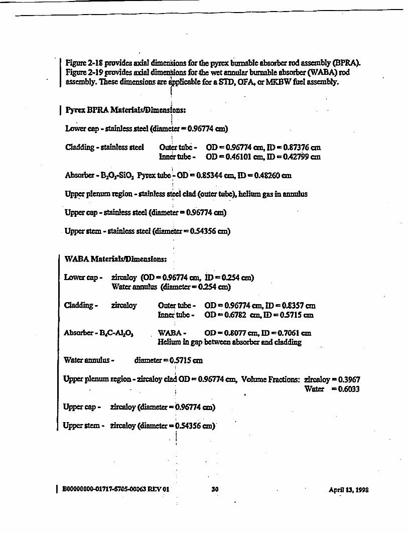
Figure 2-18 provides axial dimensions for the pyrex burnable absorber rod assembly (BPRA).Figure 2-19 provides axial dimeions for the wet annular burnable absorber (WABA) rodassembly. These dimensions are wpplicabIe for a STD, OFA, or MBW fiuel assembly.
Pyrex BPRA Materials/lDlimensions:
Lower cap - stainless steel (diameter - 0.96774 cm)
Claddin - stainless steel Outer tube - OD - 0.96774 ea, ED 0.87376 cmInnrtube- ODO0.46101 cm, ID = 0.42799 cm
Absorber - B20 3-SiO2 Pyrex tube - OD = 0.85344 cm, ID - OA8260 cm
Upper plenum region - stainless steel dad (outer tube), helium gas in annulus
Upper cap - stainless steel (m r0.96774 cm)
Upper stem - stainless steel (diamter 0.54356 cm)
WABA MateriaLhDimenslons:
Lower cap - zircaloy (OD = 0.96774 cm, ID= 0254 cm)Water annulus (diameter- 0.254 cm)
Cladding - zircaloy Outer tube - OD =0.96774 cm, ID 0.8357 cmInnertube - OD 0.6782 cm, ID =0.5715 cm
Absorber- B4C-A160, WABA- OD-0.077 cm, ID - 0.7061 cmHelium in gap between absorber and chaddhg
Water annulus - diameter 0571 Scm
Upper plenum region - zircaloy cla OD = 0.96774 cm, Volume Fractions: zircaloy - 0.3967. Water =0.6033
Upper cap - zircaloy (diameter =0.96774 cn)
Upper stem - zircaloy (diametr =0.54356 cm)
B000000O01717-C70500063 REVY1 30 April 13,19 >98.
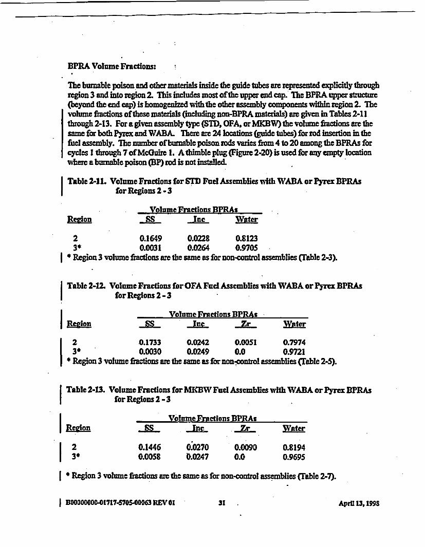
BPRA Volume Fractions:
The brable poison and other materials inside the guide tubes are recesented exlicitly throughregion 3 and into region 2. This includes most of the upper end cap. The BPRA upper structure(beyond the end cap) is homogened with the other assembly components within region 2. Thevolume fiactions ofthese materials (cluding non-BPRA materials) ar given in Tables 2-11through 2-13. For a given assembly type (STD, OFA. or MKBW) the volume fbetons are thesame for both Pyrex and WABA. There are 24 locations (guide tubes) for rod insertion in thefuel assembly. The number of burnable poison rods varies from 4 to 20 among the BPRAs forcycles I through 7 of McGuire L. A thimble plug (Figure 2-20) is used for any empty locationwhere a burnable poison (BP) rod is not installed.
| Table 2-1L Volume Fractions for SID Fuel Assemblies with WABA or Pyrex BPRAsfor Regions2 -3
Volume Froctions BPRAsRedon . SS Inc Water
2 0.1649 0.0228 0.81233P 0.0031 0.0264 0.9705Region 3 volume fractions are the same as for non-control assemblies (Table 2-3).
Table 2-12M Volume Fractions for OFA Fuel Assemblies with WABA or Pyrex BPRAsfor Regions 2 -3
I Volume Freations BPRAsRegon SS Inc r wat
2 .0.1733 0.0242 0.0051 0.79743* 0.0030 0.0249 0.0 0.9721Region 3 volume fractons are the same as for non-control assemblies (Table 2-5).
| Table 2-13. Volume Fractions for MKBW Fuel Assemblies with WABA or Pyrex BPRAsI for Regions 2 -3
I Volume Fractions BP-Redon Ss Inc Zat
2 0.1446 0.0270 0.0090 0.8194P 3 0.0058 0).0247 0.0 0.9695
| * Region 3 volume fiactions are the same as for non-control assemblies (Table 2-7).
I OOOOO0DO-1717-S7O.0540M REV 01 3 pi 31931 AprU 13,1998

Figre 2-18. Axial Dimensions for Pyr BPRAs for STD, OFA, and MKBWFuel Assemblies
Y z437.8T3 cm - -
Y c407.A73cm - -
Y =392.367 cm - -
Y E377.711 cm - -
YC.11.951cm --
Y C 0.000 cm - -
Y=-30.006cmi -- I
,.
Reglon I
UpperReactork nrnals
PyexcBurnable Poison Rod
up to 24 per Fuel Assembly
___ . Y 401.688 cmUppertm _ n Y * 398708 cn
Upu c Tp _ Y = 396.735 an
_ .
Regton 2Upper End Fltng
p _ . _
Region aUpper Fuel Ponum& End SpacerGdd
UpperPlem
RegIon 4
Active Fuel
ABS0RBER
REGI0Z'
- Yc=376A41 cm
Y a 15.761 cm- Ycl3.863an
----.-- _
Reglon 6i LawrFuel Plenumand End Fiing_
IfLwr cp Rogw
I Regton 6
Lower ReactorInernals
.
I EOOOOOD001717-6705-0006 REV GI3 Arl131932 April 13,1I998
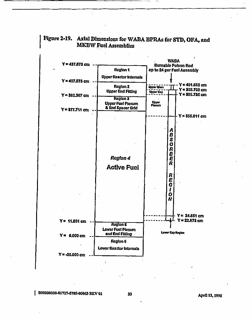
I Figure 2-19. Axial Dimensions for WABA BPRAs for STD, OFA, andMKBW Fuel Assemblies
Y :43T.873cm -
Y r-407M83 cm -
Y=392.367cni -,
y C3T7.T11 cm - '
Y r 1t.951 an -
Y= a0.000an - -
_'
Region I
Upper Reactor Iternals
Reglon 2Upper End Fting
WABABurnable Polson Rod
up to 24 per Fuel Assembly
---- I Y C401.688 cm-4 '-c, Y398.708cm
--__ - Y396.735cm
PUn Flam.-_
Reston 3-Upper Fuet Plenun& End Spacer Grd
. I
--------- 1-4 y a 365.011 cm
ABS0RBER
Region 4
Active Fuel
Region 6Lower Fuel Plenum
and End Fittng
REGI0l
Y~ r24.651 anY =22.873 cm
Low CAP Ragim
Realon 6
Lower Reactor Internals
Y C- 30000 an2 -
I BOOOOOOO -01717-5705.006 REV 0133A rl1, 9D33 April 13, 1 .M
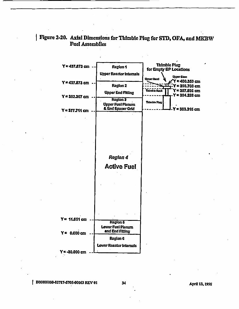
Figure 2-20. Axial Dimensions for Thimble Ping for STD, OFA, and MRBWFuel Assemblies
Y a437.S73crn - -
Y =407.8T3 cm - -
Y c392.3C7cmn --
Y =377.711 cn - -
Region I
Upper Reactor Internals
Region 2
Upper End Fing
Thimble Plugfor Empty BP Locatlons
~~ \ ~Upperflamupw fad \ 400.39cm
. : -Y c398.708 cmTh--Iui;c -Y s397.S9S6cm
*----- Y c394.28 cmT
ThIm. Pl
~~~----- Yr-383.315 cm
. _ -
Reglon 3Upper Fuel Plenum& End SpacerGid
.
Region 4
Active Fuel
Y IiSSI an
YC 0.000cm
-*1Reglon6
Lower Fuel Plenumand End Fitng
Region 6
Lower Reactor Internals
Y cD3.ODO cm _ ..
I BM00OO-01717-S705.00063 REV 01 34 April 3, 1998

Thimble Plug Materials/imensions:
Thimble plug - stainless steel (diameter = 1.08204 cm)
Thimble neck - stainless steel (diameter = 0.4826 cm)
Upper head - stainless steel (diameter - 0.96774 cm)
Upper stem - stainless steel (diameter - 0.54356 cm)
I BOOOOOD-01717-7050063REV01OA 3S AprVz 13X98

3.0 FUEL CYCLE DESIGN INFORMATION
Ihis section provides fuel assembly design data for cycles 1 through 7 of the Mecuire Unit Ireactor. Material and geometzy data for the fiel assembly components along with cycle lengthdata are presented in Section 3.1. The fuel assembly locations for each cycle, fuel enrichmentsand number of burnable absorber rods for each assembly, and control tod bank locations arepresented in Section 3.2.
3.1 Fuel Batch Data
Material and geometry data for each fiesh fuel batch present in cycles 1-7 are given in Table 3-1.This includes the cycle in which the fuel was first loaded, the fuel assembly type, the enrichmentand kilograms of uraium in each fuel assembly (by batch), the diameter of the fuel pellets, theBPRA type, and the type of fuel assembly grid material. The radial dimensions of the fuel clad,instruzmet tube, and guide tube are also prented. In addition, material and radial dimensionsfor RCCAs and BPRAs are prvided. This data should be used in modeling each fuel assemblytpe for burnup calculations and the reactor criticality calculations for the statepoints defined inTable 3-2.
The length of each fuel cycle, expressed as efective-full-power-days (EFPD), is provided inTable 3-2. Ihe time during each cycle where statepoint criticality data was measured is alsopresented.
IBOOOOO041717-6705-00063 REV 01 3 pi 31936 April 13,1993
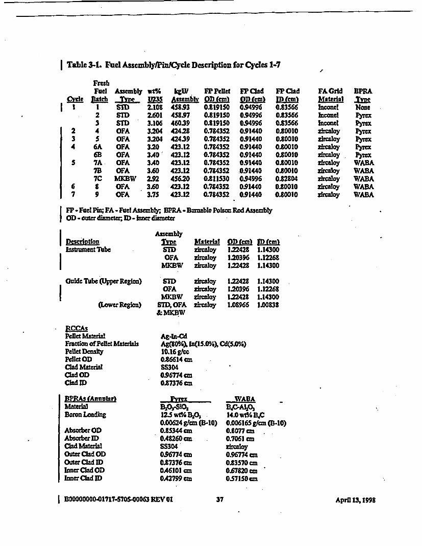
I Table 31. Fuel Asseutbly/Pin/Cycle Description for Cycles 1-7
FreshFuel AssembRy wtA kgUI FP Pellet WPClad
Clyle Batch Type W3S Assembly OD (cm) O D (cmI I Sll 2.108 4S5S3 0.819150 0.94996
2 STD 2.601 4S8.97 0.819150 0.949963 SllD 3.106 460.39 0.119150 0.94996
2 4 OFA 3:204 424.28 0.784352 0.914403 S OFA 3204 424.39 0.7843S2 0.914404 6A OFA 320 423.12 0.784352 0.91440
6B OFA 3A0' 423.12 0.7843S2 0.91440S 7A OFA 3A0 423.12 0.784352 0.91440
70 OFA 3.60 423.12 0.7843S2 :0.914407C WMICW 2.92 4S6.20 0.811530 0.94996
6 8 OFA 3.60 423.12 0.784352 0914407 9 OFA 3.75 423.12 0.784352 0.91440
FP CladID (cm)0.835660e3S660.835660.835660.800100.80010080100.800100200100.80010028040.800100.80010
FA Grid BPRAMoterisl _IueInconel NoneIconel PyreIncoael PY=ezIaoy Pyezrcaloy PyWAzircaoy PYIexzircaoy. P yre
zhvaoy WABArcaloy WABA
zircaloy WABAzhvaoy WABA
FP - Fuel Pin; FA - Fuel Assembly; BPRA - Biniable Polson Rod AssemblyI OD uter diameter, ID - inner diameter
Instrument Tuc
GuId Tube Upper Region)
(Lower Region)
ECCAsPellet MaterialFraction of Pellet MaterialsPellt DensityPCllet ODClad MatraiscladODClad D
BPRAs (Annular)MateraBoron Loading
Absorber0)Absorber IDClad MaterilOuter Clad ODOuterClad IDInner Clad ODInnerCladID
Assemblyfle Material OD (cm) M MlISTD zircaloy 1.22428 1.14300OFA irCaloy 120396 1.12268
MKBW zircaloy 122428 1.14300
SD ziraloy 122428 1.14300OFA zrloy 1.20396 1.12268
MKBW zircaloy 1.22428 1.14300STD,OFA zcaloy 1.08966 1.00838&MKBW
Ag-lnCdAg(80°h), WIn5. ) Cd(S.0%)10.16 gfCC0.86614 cmSS304096774 cm0.87376 cm
WAEABj0,SiOa BPA1I0312.5 wvt% BA 14.0 wle B*C0.00624 gfcm (B-10) 0.006165 gfl (B-10)0.85344 cm 0.1077cmOA8260cm 0.7061 cnSS304 zMIrCuy0.96774cM 0.96774cm0.87376cm 0.83570ccmOA6101cm 0.67820 cm0A2799 cm 0571S0cm
I B0OOO0OO-01717-570S.00063 REV31 37 April 11, 1998
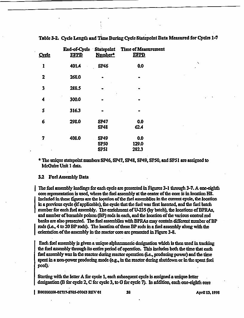
Table 3-2. Cycle Le1gth and Time During Cycle Statepoint Data Measured for Cycles 1-7
CyLeEnd-of-Cycle
4F1D
401A4
StatepointNumber*
SP46
Time of MeasurementE"fl
0.01
2
3
26L.0
288.5
300.0
316.3
4
S
6 298.0
408.0
SP47SP48
SP49SP50SP51
0.062.4
0.0129.0282.3
7
U Ihe unique statepoint numbers SP46, SP47, SP48, SP49, SPSO, and SPS1 are assigned toMcGuire Unit 1 data.
3.2 Fuel Assembly Data
Ihe fuel assembly loadings for each cycle are presented in Pigures 3-1 through 3-7. A one-eighthcore representation is used, where the fuel assembly at the center of the core is in location H8.Included in these figures awe the location of the fuel assemblies in the current cycle, the locationin a previous cycle (if plicable), fih cycle that the fIel was first inserted, and the fuel batchnumber for each felc assembly. The enrichment ofU.235 (by batch), the locations of BPRAs,and number of brnable poison (BP) rods in each, and the location of the various control rodbanks are also presented. The fuel assemblies with BPRAs may contain different number of BProds (ixe, 4 to 20 BProds). The location of these BP rods in a fuel assembly along with teorienttion of the assembly in the reactor core are presented in Figure 3-8.
Each fWel assembly is given a unique alpnueric designation which is then used in trackingthe fuel assembly throug its entire period of operation. This includes both the time that eachfuel assembly was in the reactor during reactor operation (Le, producing power) and the timespent in a non-power producing mode (e.g., in the reactor during shutdown or in the spent fuelpool).
Starting with the letter A for cycle 1, each subsequent cycle is assigned a unique letterdesignation (B for cycle 2, C for cycle 3, to 0 for cycle 7). In addition, each one-eighth core
I BOODOOOCO-01717-570S-00063 REV 01 38 Aprfl 13, 1998
location is assigned a unique number. As noted in Table 2-2, the McGuire Unit 1 reactor -contains 193 fuel assemblies. Assuming eighth core symmetry reduces this number to 31 fuelassemblies represented. Thus, the assemblies are numbered 1 through 31. Starting at the centerof the core, location Kg is number 1. Numbers 2 through 8 are assigned to locations 08 throughAS. Proceeding from left to right (then down), number 9 is assigned to location 039, number 15to location A9, number 16 to location F10, number 22 to location El1, etc., to number 31 beingassigned to locationBl3.
Using this nomenclatue, the assemblies in cycle I are labeled Al (for H8) through A31 (forB13). For subsequent cycles, a complete set of labels is not requiredsince a combination ofburned and frsh fuel is used. From Figure 3-10 it is seen that the fiast fresh fuel assemblyencounteedin cycle 2 is in location A8. Thust he cycle 2 labeling for new fuelstart withassembly BS. Figures 3-9 through 3-15 were constuted by applying this jomenclate to thefiul assembly location data given In Figures 3-1 through 3-7. Note that the nomenclatureaccommodates the shuffin ofsymmetric components of fuel assemblies to two separatelocations in the one-eighth core reprsentao. Iis is seen in Figure 3-10 where assembly A21firm core location Al0 (representing 8 fuel assemblies in the core) in cycle I was shuffled forcycle 2 to core locations FI1 and 09 (each representing 4 fuel assemblies in the core). Theassembly represented at location 09 was then given the identification A2la
One of the four MKBW (batch 7C) assemblies represented by number E2 at location FIO incycle 6 (see Figure 3-14) was removed from the core at the end of cycle 6, and the remaiingthree assemblies were shuffled into full core locations symmetric to location 09 in cycle 7.Assembly number E12 (batch 7A) from core location D8 in cycle 6 was shuffled to location G9in cycle 7. For the statepoint calcuations in cycle 7 (SP49, SP50, and SPS 1), a one-eighth corerepresentation can be used with assembly number E2 inserted in location 09. Howeer, for thebeginning-of-cycle (BOC) statepoin (SP49), a full core representation should be analyzed withassembly number E12 in location G9 and assembly number E2 in the three full-core symmetriclocations (iLe, locations J7, (7, and 19). This will quantify the effect on kff of making the one-eighth core aoximaton for the cycle 7 staepoints.
B00000000-01717-5705-0000 REV 01 39 AprS1 13, 998I
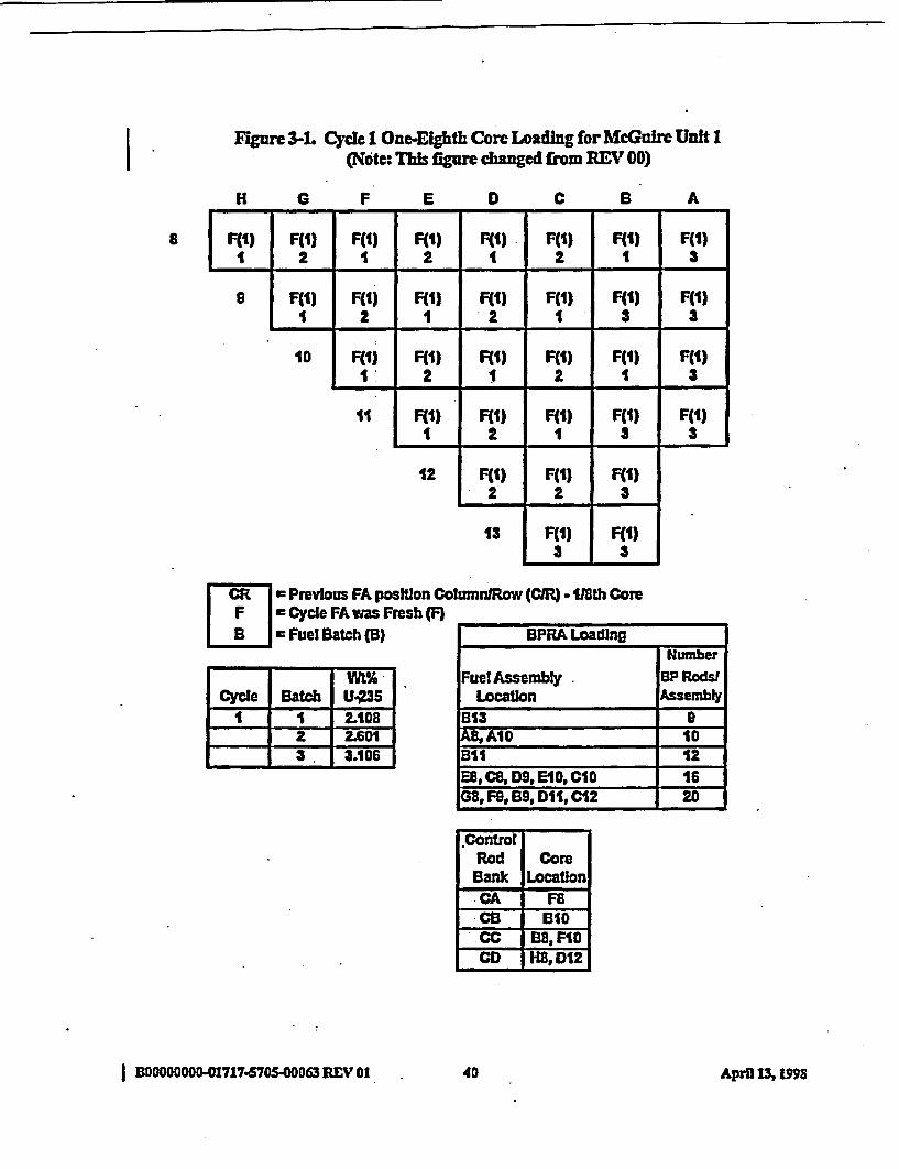
I Figure 3-1 Cycle 1 One-Eighth Core Loading for McGire Unit I(Note: This figure changed from REV 0)
H G F E D C B A- . . .- .- V
8 jFC1)
-I.z
8
F(1) F(13 F(S) F(1) F(1J F(1) F(.)2 1 2 1 2 1 3
F(1) F(1) F(1) F(1) F(S) F(1) F(1)1 2 1 J 2 ' 3 3
10 F(S) F(1) F(1) F(1) F(1) F(I)I 2 1 2 1 3
11 F(1) F(S) F(S) F(1) F(I)I1 2 '1 3 3
- - - I. - I. -
12 F(1)2
F(1)2
F(l)3
- i. - I. -
IfS F(1)3
F(1)3
ClRfl Prevous FA position Column!ow (CIR) - 118th CoreIF I Cycle FA was Fresh (F)
B ! . Fuel Batch (B)
* - - . M A,
Cycle Batch U-235I - - LI- S
2 2.ML 1 3 3.106
BPRA LoadingNumber
FuelAssembty BP RodsJLocatlon Assembly
B13 9A8,A10 10B61 12EGC8,D9,E1D,CI0 16G8, FS.B 19, Di IC12 20
ControlRod
BankCACB
.CCCD
CoreLocation
F8B10
B8, FIGHS, D12
IB000000O-01717-S70-00063 REV 01 40 Aprfl 13,199S

IFre 3-2. Cycle 2 One-Eighth Core Loading for McGuire Unit 1
(Note: This figure was added to REV 01)
H G F E D -C B A- . - * U - * - p a . - -
B108 F(1)Ii
B
C8 AID Gs 611 B8 DM2F(1) F(I) F(S) F(S) F(S) F(S) F(2)
2 3 2 3 1 2 4AID 612 C10 69 E10F(1) F(l) F(1) F(l) F(1) F(2) F(2)
3 3 2 3 2 4 4C13 All D11 C12 09
10 F(1) F(1) F(I) F(1) F(l) F(2)3 3 2 2 2 4
B11 AS FSI1 F(1) F(1) F(I) F(2) F(2)
3 3 2 4 4�9�9���* -
12- ASF(1)
3
613F(1)3
F(2)4
- I. ~__
13ES
F(.)2
F(2)4
CR = Previous FA posiUon ColumnRow (CR) - 118th CoreF a Cycle FA was Fresh (F)
a Fuel Batch (B) BPRA Loading --- IWL%'
Cycle Batch U-235
2 1 2LD82 26013 3.1064 3204
NumberFuel Assembly BP Rodst
Location AssemblyB9,811
ControlRodBank
. CA
CC
CoreILocation
F8B10
B8, FIOH8, D121
1 B1000000-01717M70500063 REV 01 41 April 13, IM9
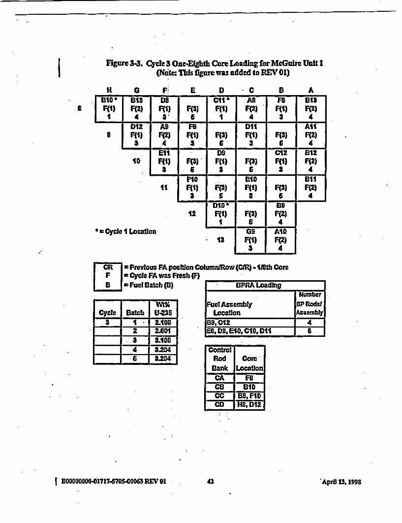
I. Figure 3-3. Cycle 3 OneElghth Core Loading for McGuire Unit I(Note: Tis fgere was added to REV 01)
H 0 F. E D *C 8 A-- F - U U U U U - U
6 10'a F(l)
II- .
9
B13 D8 C11' AS F8 B0SF(2) F(1) F(p) F(1 F(2) F(.) F(2)
4 3 6 1 4 3 4D12 A9 FS D11 AllF(1) F(2) F(I) F(S) F(l) F(3) F(2)3 4 3 6 3 6 4
Ell D9 C12 B1210 F(l) F(3) F(l) F(3) F(1) F(2)
3 6 3 6 3 4F10 E10 611
11 F(l) F(S) F(1) F(O) F(2)3 6 3 6 4
12DIDaF(l)I
F(*)6
B9F(2)4
- _ - _ 1
* C Cycle 1 Location13
IGSF(f)3
AIDF(2)4
CR = Premvous FA positon ColumnlRow (CR) 118th CoreI F I Cycle FAwas Fresh(F)
B~i Fuel Batch (B)
Wt%Cycle Batch U-235
3 1 2.1082 2.601
.3 3.1064 3204
1 -I6 3.204
BPRA LoadingNumber
Fuel Assembly BP RodsWLocation Anembly
B9,C12 4ES, D9, E10, CIO, DII 8
C on r oRodBankCACBccCC
Core
LocationF8e
BIDB8, FloHS, D12
IE00 OOO.O-1717-.570S.40063 REV 01 4 pi 31 942 -April 13,1998
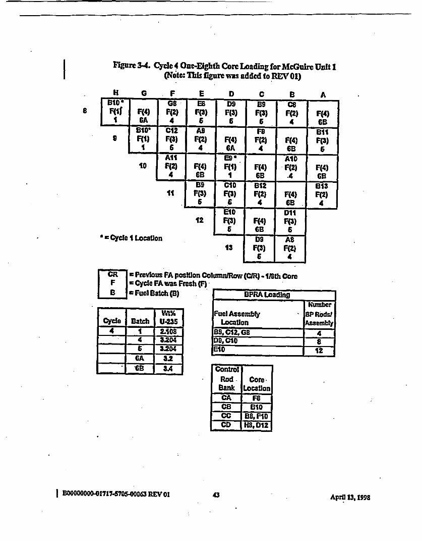
I F-gnre 3-4. Cycle 4 One-Eighth Core Loading for McGuire Unit 1(Not: his figre was added to REV 01)
H 0 F E D C B A
8BtO * 8 EB_ D9 B9 C8 CsF(If F(4) F(2) F(3) F(p) F() F(2) F4)
1 CA 4 6 6 6 4 6B
9a1u-F(1)
1
Ulz
F(O)6
owF(2)
4F(4)6A
FeF(2)
4F(4)6B
ellF(3) I
9GA SBF(2) F(2) F(S)
a f � f a 4. � a �f. �- .1 �.4 4
10A111F(2)
4F(4)GB
9UMF(i)II
F(4)GB
AIDF(2).4
F(4)6s
-4 65- I � I --- 4 � *1 - I -
tt F(3)6
CroF(O)
6
t12F(2)
4F(4)68
813F(2)
4_,_~~~~~6 4
12 F(O)6
F(4)Gs
DtiF(3)
6* = Cycle I Location
a __
13D9
F(3)6
AB
F(2)4
:R r= Previous FA position ColumnlRow (CR) - 118th CoreF = Cycle FA was Fresh (F)LB s Fuel Batch (B)
Wt%CYcle Batch U235
4 1 LI08D4 3.2046 3204-
GA 3.2- -A., . GB 3A
BPRA LoadingNumber
Fuel Assembly BP Rods!Location Assembly
139,0108E10
ControlRod
BankCACB
CD I~
Location
iBIDB08, F10
Hf8, D12
I 1OO00 OOO-01717-570S40 003REV01.3 p111,1943 April 13,1998
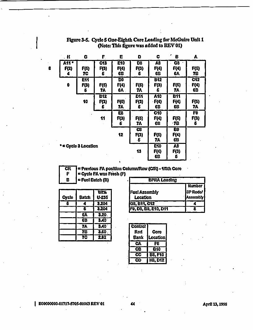
I Figure 3-5. Cyde S One-Eighth Core Loading for McGuire Unit 1(Note: This figure was added to REV 01)
H G F E D C 'B Aq -9' 9' �9' -� 9' - U. -
All a8 F(2)
4- a
e
C13 EID D8 AU G8F(5) F(3) F(4) F(3) F(4) F(4) F(S)rC 6 eB 6 GB GA 7BElt D9 B12 C12F(3) F(S) F(4) F(S) F(3) F(S) F(4)
6 7A GA 7A 6 7A 6E3D12 DII AID 611
10 F(3) F(6) F(3) F(4) F(4) F(S)6 7A 6 GB 6B _A
E. CID FI11 F(3) F(S) F(4) F(S) F(S)
6 7A 6B 713 6-4 * -4 - 4-
12CHF(p)
6F(S)7A
EUF(4)Gs
- _ - _
* = Cycle 3 Location13
E-0F(4)GB
A9F(S)
6
CR r Pteviotus FA position Co umrnJRow (CIR) - 118th ComreF zrCycle FA was Fresh (F)[BI] Fuel Batch (B) .*I B-F- Loading-
Cycle Batch U-2356 4 3.204
6 3204GA 3.20GB AD-TA 3ADTS 3.007C 2.922
Nunber
Fuel Assembly BP RoWLocation Assembl
GS, BSi, C12 E ) 4FS, D9, B9, E10, DII I a
controlRod
BankCA CACCA
CD
CoreLocation
F8I B10I s8, FloH8, D12
I BOO000000-01717-S7OS00063 REV 01 44 April 13, 1"S
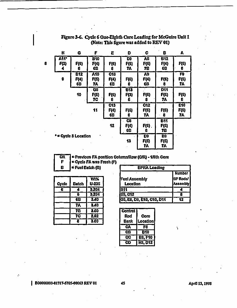
I Figure 3-6. Cycle 6 One-Eighth Core Loading for McGuire Unit I(Note: This figare was added to REV 01)
HI G F E D C B A
8AW BID1 D9 AS 612F(2) F(6) Ff4) F(6) F(6) F(6) Ff4) F(6)4 a 69 8 7A 6B 8~~~~00 A _
S612Ft4)6B
AIDF(5)7A
CIOF(4)6B
F(G)8
A9F(4)6B
F(6)8
-FF(5)7A
Ff4) F(4) F(S)69 60 TAI. - .1� L I -
IDGB6F(S).7C 6
613FO3)5
F(G)S
D11F(S)7A
F(6)8
- ' - I. - I. � � - . -
IllC13F(4)6B
F(6)8
C12F(S)TA
F(S)*
EIOF(Q)7A
- � - I. - I. - � -
12C8
F(4), 6B
F(6)8
B11F(S)70
_ _~0I * Cycle 3 Location13
ID9F(S)7A
B9F(6)TA
CR e Previous FA position ColumntRow (CMR) - 11th CoreF I * Cycle FA was Fresh (F) -= Fuel Batch (B) IPIRA Loading
-~ - -WI%Cycle Batch U-235
6 4 3.2046 3.204
160B 3AA0TA 3A0
- 7B 3.607C 2928 3.60
.NmberFuel Assembly BP RodsJ
Location AssemblyB11 4B9, C12 SG8, ES, DS, E10, CIO, D11 12
ControlRodBankCA0CBCCCD
CoreLocation
FTFBID
IB8,FID
I BO0000000-01717-570540063 REV Q1 4S Aprfl 13, 1998
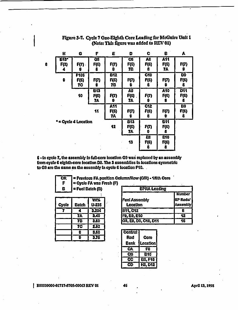
I Flguri 3-7. Cycle 7 One-Eighth Core Loading for McGuire Unit I(Notc: This fgure was added to REV 01)
H G F E D C B A
8B013 GE CB AS AllFf2) FM ff6) Ff7) F(5) ffq) F(5 Ff)4 S 8 9 7B 8 7A -
9FISF(S)70
Ft7)9
B12F(S)7B
Ff7)S
Ci1F(S)
8FO7)9
D9F(6)
8__ _mm 4 _ m -
10B13F(S)7A
F(7m9
ASF(S)7A
Fm9
A10F(S)
8
Dl1F(S)
8m m~ _m _ 9 m 9
IIAllF(6)7A
FmT9
C12F(S)
8Ff7)
9
u9F(6)
8m m 4m . -4t
* * Cycle 4 LocatIon12
513F(S)7A
F(7)9
511F(S)
8_ _ _. m m _m
13Ee
F(S)8
EIOF(6)
a
-.In cycle 7,the assembly Infu~llcore location G9 was replaced by an assemblyfrom cycle 6 efghth-core location D. The 3 assemblies In locations symmetricto G9 are rhe same as the assembly In cycle 6 locaton FIG.
. Previous FA position ColumnlRow (CIR) - 118th CoreIFI Cycle FA was Fresh (F)IBI mFuel Batch (B) I BPRA Loading
a... W- -" F
mm mm. WI%Cycle Batch U-235
7 4 3.204TA 3A0TB 3A0TC 2926 3.600 3.75
Number
Fuel Assembly BP RodsJLocation Assembly
BlP, C12 8FB. B, E10 12,8, ES, D9, CIO DDi 16
ControlRodBank
ICACB
CD
CoreLocation
FSBIG
BB, FIGH8, D12
I BOooooGom041717-5705-00063 REV 01 C6 AprD 13, 1"S

I Figure 34. Burnable Poison Rod Locations within a Fuel Assembly(Note: This figre was changed for REV 01)
U Guide Tubes andI Instrument Tube 20 Burnable Poison Rods 16 Burnable Poison Rods
12 Burnable Poison Rods10 Burnable Poison Rods(BP toward core center)
9 Burnable Poison Rod(BP toward care center)
I:
S Burnable Poison Rods4 Burnable Poison Rods
(CyC Mds2,34,&5) :4 Burubhle Polson Rods
(Cycle6)
I
I
* GuideTube0
Izstr cnt Tbe
0
Burnable Poison Rod
I BOOOOOOOO.01717-6705700063 REV01 47 April 13,1998
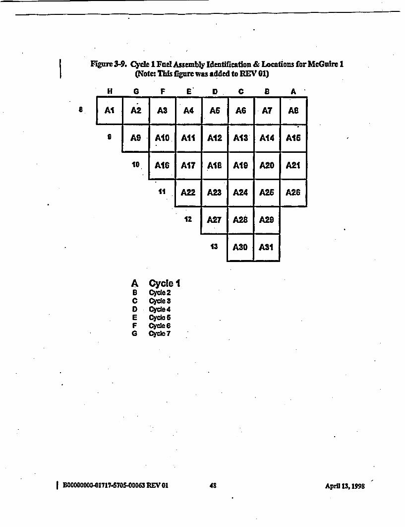
IFguwre 3-9. Cycle 1 Fuel Assembly Identification & Locations for McGuire I
(Note: This figure was added to REV 01)
H G F E D . C B A
8 A|A2| A3 | A4 AS AS A AS
9 ASg A10 All � A12 A13' A14 A16
- I - 1 -* * - 4
10 AIS A17 AIS AIS A20 A21A17 AIS A20- I. - .I-� - '0* - e -
11 A22 .A-22 A24 -A-29 A26
12
. - 1 - 4 * -
A27 A28 A29
- I . 4
13 A30 AS1
A Cycle IB cycle 2C Cycle 3D -CYc~e4E Cycle 5F Cycle 6G CYcde7
I BOOOOOOOO-01717-570S-00063REV01 48 April 13, IM
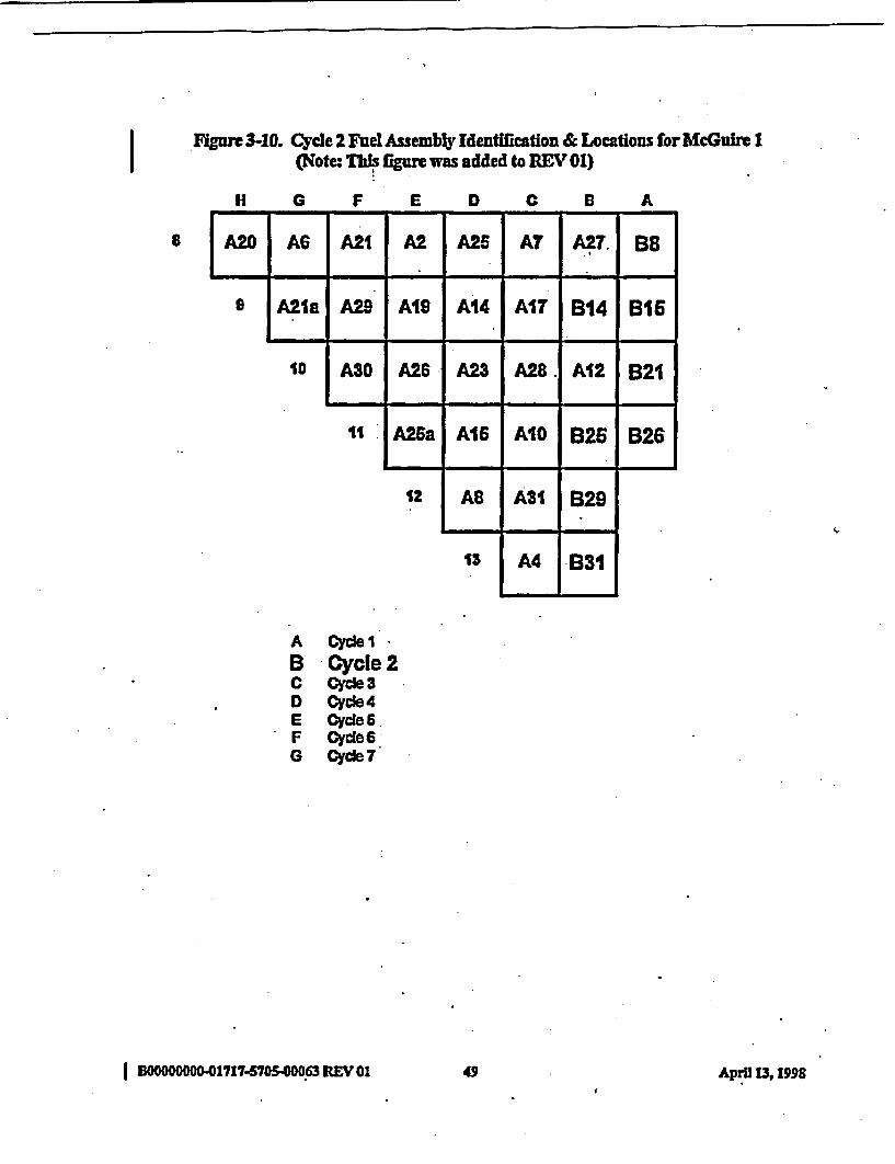
I Figure 3-10. Cycle 2 Fuel Assembly Identfication & Locations for McGuire 1(Note: Ths figure was added to REV 01)
H G F E D C B A
8 JA210 A| A2l |2 A2 j| A27.BB
9 A1la -AIS A19 AU A17 A 14 AlT B 14 B IB16-4 - I - - I - 4 - I.. . ,
10 A30 A26 .- A13 A29. A12 B21- _ - I - . - - . -
dl I A26a A16 AIO A26 B26- . , 49 * -
12 ARAII,
A31 B29
13 A4 B31
A QYd~e1IB -Cycle 2C QYde 3D Cyde 4E Oyd 6.F Cycde 60 Cycde7
I 00000 0O -WOS705.063 REV 01A 49 AprH 13,1999

IFigure 3-11. Cycle 3 Fuel Assembly Identification & Locations for McGuire 1
(Note: T figure was added to REV 01)
_H G F - E D C B A
a A.20aB3 A2- C4 A24 B8 A21 B31aCycle I Cycle I
S A8 B15 AIR 012 A66 � C14 B26
- __ - U 6 6
10 A26a C17 A14 CIO A31 629
- I. - I* - t - q - q. -
1II ASO C23 A26 ^10Crj-.6 626
- I" - -9-9-
12 AIBCycle I
C28 B14_ i
.13 A21a 621
A Cyce 1B Cycle 2C Cycle 3D Cyde4E cyce 6F Cyce 60 Cyce 7
I BOO OOOOOO-171 7.S7050063 REVOI oApi 3,19so April 13,1998.
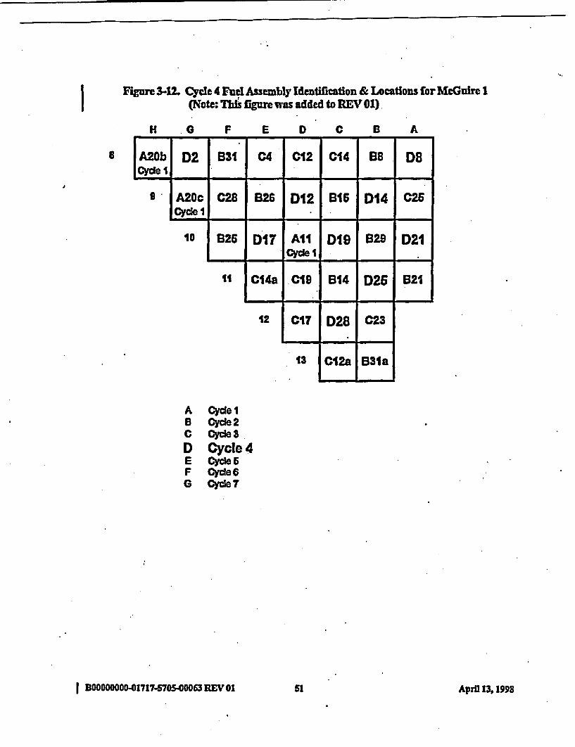
I Figure 3-12. Cycle 4 Fuel Assembly Identification & Locations for McGuire I(Note: Ths igure was added to REV 01)
H G F E D C B A
a A20b D2 B31 C4 C12 C C14 |B8 DSCyclel I I J
J
I A2OcCyle I
028 B26 D12 B16 D14 C26
- _ _ - t - * ,. -
10 B26 DI1T AllCY~e I
D19 B29 D21- t �3*���I. - q -
t1 C14a .cis B14 D26 B21
- I - _
12 CIT D28 C23-
13 C12a B31a
A cyle IB Cycle 2C Cycle 3D Cycle 4E Cyde 6F cycle 6G Cy e 7
I B00000000-01717-570S00063 REV 01 Sl Apri 13, 199
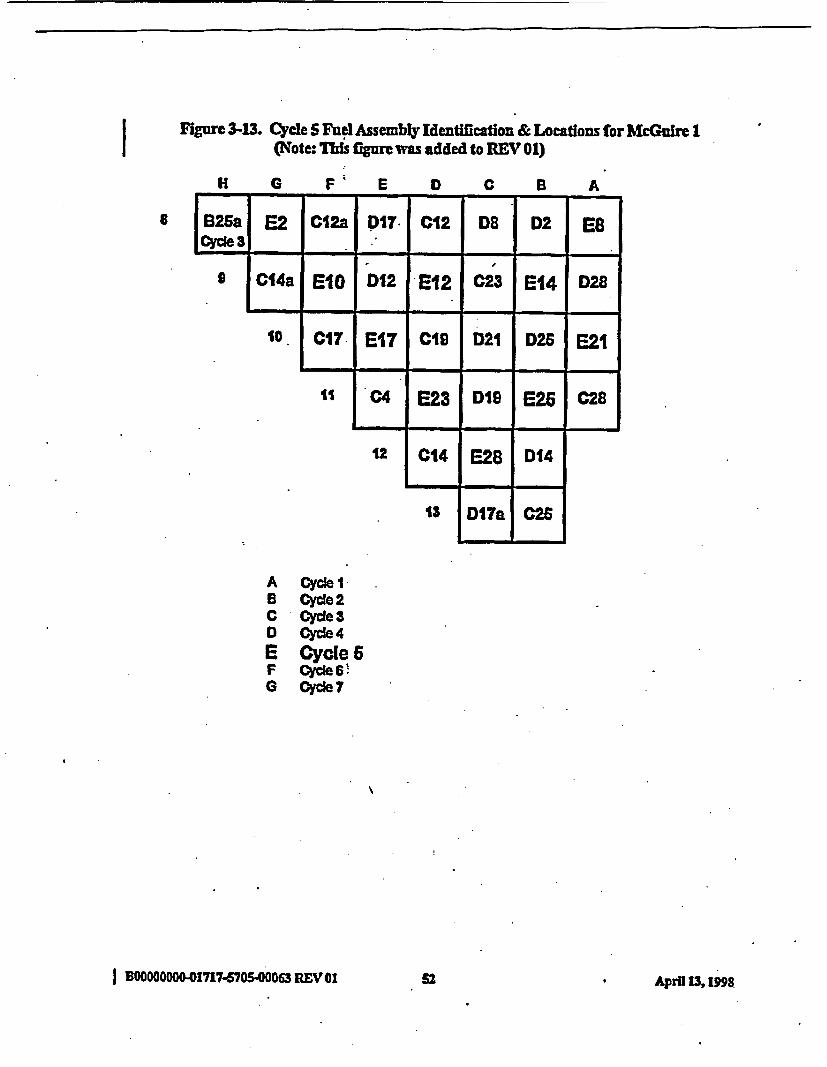
I Figure 3-13. Cycle 5 Fuel Assembly Identification & Locations for McGuire II (Note: This fiure was added to REV 01)
H G F* E D C B A
8 iri s XI 1-1B2a E2 C12a DIT7I C12 DS0 D2 ESCycl 3_ 1 I__ _
9 C'14a ElO D12 E12 C23 E14 D28
50 C17. E17 C19 021 D26 E21
1 0C4 E23 D1S E26 C28
12 C14 E28 D014
1S D17a C26
.- -
A Cycle IB Cycle 2C cyle 3D Cycle 4E Cycle 6F Gyce 6'G cycle 7
I BOOOOOOO-01717S705-00063 REV IA E2 April 13, 1998

Figure 3-14. Cyde 6 Fuel Assembly Identification & Locations for McGuire 1I (Note: Thu figure was added to REV 01)
H 0 F E D C B A
8 825b F2 D2S F4R E12 ES D14 F8Cycle 3 .] D14a E21 D21 F12 D28 F14 E10
10 E2 F17 C26 F19 E23 F21
. 1 D17a F23 E28 F25 E17
12 DS F28 E26
13 E12a E14
A ycle IB cycle 2C Cycle 3D Gycle4E Cycle 6F Cycle 6G Cycle 7
I 0000000-01717470S000 REV 01 S3 Atpril 13, 1998
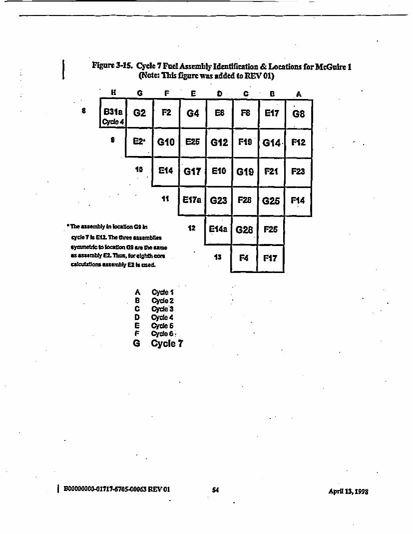
' Figure 3-15. Cycle 7 Fuel Assembly Identification & Locations for McGuire I(Note: This figure was added to BEV 01)
*H 0 F E D C B A
8 SB3a G2 F2 G4 ES F8 E17 GsCycle 4
9 E2E GIO E26 G12 FIG G14- F12
10 E14 G17 EIO GI1 F21 F23
51 E17a G23 F28 G2.6 F14
T*oau IncWonG h2In 12 E14a G28 MSyce 7k EU The dmme. susmbes..
symmqlo kLcwag 095 am mmasasusambL Thusforelghtfom 13 F4 F17calcaons asse k usekL
A Cyle I8 Cyce 2C Cycle3D Cycle 4E Cycle 6F Cycle 6G Cycle 7
I BOOOOO0001717-P70S.00063 REVOI 5 pi1,19S4 April 13,1998
To aid in the burup calcutions, and thus the generation of isotopic data for the statepointcalculaftons, the information provided in Figures 3-1 through 3-15 was reduced to two tables.Table 3-3 tres each fuel assembly (and subsequent split by shuMling symmetric components tomore than one location, If applicable) by assembly identification and cycle firom the time theassembly was first inserted in the reactor to either cycle 6 or cycle 7. Those assemblies whichsplit for a subsequent cycle (Le., with an UV" or fb" designator) carry a hyphen ( - ) designator inthe cycle column to indicate those cycles where the asemblies are present prior to the split Thiswill aid the burnup calculation process by indicating whe redundant data generation is notrequired. Note that only those fuel assemblies which conrtibte to the statepoint calculations incycles 6 or 7 are included in this table. MT e are the fuel assemblies that require burnupcalculations. The location of each assembly In each cycle is indicated by the coordinates givenin the figures (e.g., H8, B 13).
Table 3-4 is a repeat of portions of Table 3-3 where control rod bank insertion and burnableabsorber (BA) loadings are given for those assemblies that contained control rods or burnableabsorber rods during cycle operation. Control rod insertion and burnable absorber rods must bemodeled in the burmup calctions for those assmnblies and axdal locations where either type ofrod ae present (More data concerning control rod insertion time by axial node is given inSection 4.) The rod bank indicator CD is given for those assemblies and cycles where rod bankCD was inserted. (Thisis the only bank inserted during nonnal cycle operation.) e burnableabsorber loadings are given as Ome number of brnable absorber (or burnable poison) rods presentin the fuel assembly. For those cycles where the rod bank or the burnable absorber rods are notpresent, the assembly presence in the core is indicated with an "X".
I BDO0OO -01717-670-00063REVI0 Ss AprHl 13, 1998
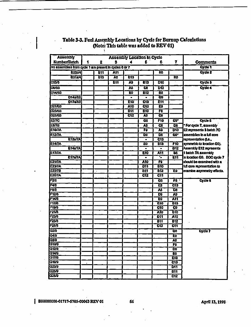
ITable 3-3. Fuel Assembly Locations by Cycle for Burnup Calculations
(Note: This table was added to REV 01)
Assembty Assembly Location In CycleNumberIBatch 1 2 3 4 6 6 7 Comments
No assemblies ftm cycle I am presenti cycles 6 or 7 cycle 1M25ht4 611 All cycle 2931814 B13 A BS 1H
GM5Th 911 o A 613 DtO Cyde a
0W AB_ Ca D12 Cycle 4DU415B 99 912 98
DIM7 EIO C13 Ell021163 AI1 CIO E905MB 911 610 F8
C12 AO CoE217C 0B8 FIO G9 Cycle 6Eg _. AS CS WS Forcycle 7.ssembly'E1017A F9 AD DI1 E2 wpeserds 3 batch 7E1217A D9 DS Gr assemblims h a fuf
' E12aU - . C13 reptesea on (Le..514(7A - 9 613 F1O symmeWcto location G9).
E117 - - D-m12 A E12 epresentsE1717A E10 All 98 I batch 7Asse
El7a7 . . Ell In bcdonG9. OC cydoe 7E21/IA AID F6 shoLd be examned wth aE23rIA DOi Bt1 5 cm Mpresenplon to=W8 91 1 812 E9 exanmine asymmetryeffeds.E2MA C12 CelFM8 -B - F8 Cyle 6F48S ES C13:8,8 BAS CSFI2F De AS
:12t- - -- - A
1418 09 AllP1718 E1o 913P19/8 CIO CsP211B AID BI1F23/5 DII AIDF25/8 a11 912:28/8 C12 CIl3219 aS cycle 73U/9 =8
0819 AS31W9 Fe
G12h9 D9
014/9 - - - - 901719 EtI
199S CIOG231 Dt1G25M Ell
02_1 C12Ga - -- -
I DOOOOWOO O-01717-705S00063REV 01 56 April 13,1998.
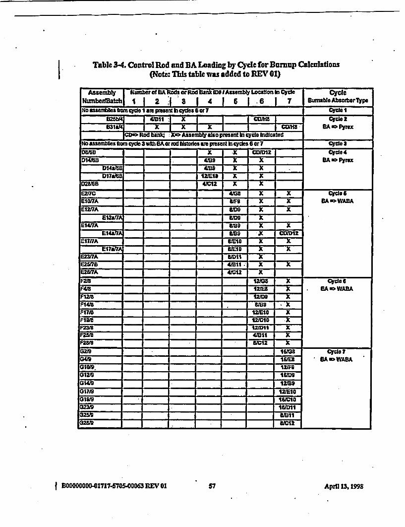
I Table 3-4. Control Rod and BA foading by Cycle for Burnup Calculations(Note: This table was added to REV 01)
Ammbl| Number of A Rods or Rod Bank IU IASs.mbly Lcaion In Cycle CycleN edBatchl 1| 2 .| 3 | 4 | 6 | * 6 | 7 BunableAbsotrTypeNo tlesfomcyde I1ae presIn con 6 cwr7 Cyclel
41 1 ~~4FBl X CCmcbA I cycle 2~~~~~~~~~~~~~~~~~~~~~~~~~~~~~~~~~~~~~~~~~~~~~~~~~~~~~~~~~~~~~~~~~~~~~~~~~~~~~~~~~~~~~~~~~~~~~~~___ ylB31m4 X X X COI 8BA Pyrx
Rodn; Ko Assemr lsko pmresent hi cycle dcaledNo asembIes *omce 3 wth BA or bd bistoes we pest hi cydes or 7 Cycle 3DBMB K X X CDID12 Cycle 40146B - -9 - X | X - BA M Pyrox
D148AM _____ 4/BS x xD17i 12UE10 X X
02Q8fB 4=1.2 X XEZ17C 4168 X X Cycle 6Eli 0/A U X X BA " WABA
1217A £1K X
cl4iTA _ .WA5VB9 X XEIWaIA MS5 K CDIDIZ
E1717A W1OO X X
E~2UE7A 41012 XF2i8 121t; X Cycle 6F48 1ZIEt . EA."WABAF1218 X1 KF1418 UB9 XF17J8 12110 XF19M/3 121010 XF23_ 12011 XF25ta 41911 XF M518 £1012 XG29 - - - 168 Cycle0419 .11S BA WABA10/9. 12lIF
G1219 16109G1419 12159G07I9 125E1009g9' 161010
G23W9 161011G2W"9 wa116 8 / 1C012
I BOOOOOOOO-1717-570S.00063 REV 01 57 Aprll 13, 199

4.0 CORE OPERATIONS AND STATEPOINT INFORMATION
This section provides core operations data for the bumup calculations required to generateisotopic concentations for the statepoint evaluations. The measured critical conditions for thestatepoints evaluated are also contained in this section.
4.1 Core Follow Da-a
The use of commercial reactor criticality data for model validation requires detailed knowledgeof how the reactor was opeated for the lifetime of every fuel assembly ooniributing to thecriticality database. This is necessary in order to adequately model the conditions for burupcalculatios at each axial location of each fuel assembly represented in the reactor core for eachstatepoint evaluation. Thus, core follow calculations based on core operation data are used toprovide local conditions as a fimetion oftime to be used for all bumup calculations performed insupport of the statepoint evaluations. In addition, measured global data such as rod insertionsand boron letdown data are also provided.
The core follow calculations provide tree-dimensionsl thermal-hydraulic feeack andbumup data. These data are presented at axial node locations. The nodal spacingsfor the axialnodes are presented in Table 4-1, Where node I represents the top axial node in the reactor core.Tables 4-2 through 4-46 provide axial bumup, profiles for each assembly at each datapoint orstatepoint along wit axial fuel temperature and moderator specific volume distributions used inthe bumup calculations between datapoints or statepoints. The statepoint evaluations forMcGuire 1 were performed at beginning-of-life (0 EFPD of cycle 1), BOC of cycle 6 (0 EFPD),62A EFPD of cycle 6, BOC (0 EFPD) of cycle 7,129.0 EFPD of cycle 7, and 2823 EFPD ofcycle 7. Some of the fuel assemblies present In cycle 6 and 7 for the statepoint evaluations wereinitiallyinserted inffie core in cycles 2, 3, 4, and S. No cycle I assemblies appearincycles 6 or7. The modeling of fuel assembly operating history for assemblies which were first insertedprior to cycles 6 or 7 require burnup, fuel temperature, and moderator specific volume data forthe cycles since the fuel was first Inserted into the core. These data are provided at datapoints forthe cycles prior to cycle 6 and at statepoints for cycles 6 and 7. The data is also given by axialnode location
Control rod insertion time (by axial node) for each assembly with a control rod inserted duringcore operation is provided in Tables 4-47 trough 4-SO. Tbis data was also obtained firom thecore follow calculations based on oare operation data. In addition, boron letdown data for cycles2through 7areprovidedInTable4-51. Boronletdowndatafor cycle isnotrequired sincenofuel assemblies from cycle 1 are present for the statepoint calculations in cycles 6 or 7 and noburnup calculations are required for cycle 1. The data provided in Table 4-51 are coefficientsfrom a linear regression fit of core operation data for each cycle.
I BOOOOOOO-01717-700500063 REV 01 s8 April 13, 1998
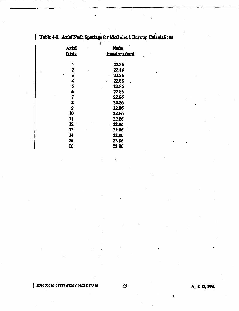
I Table 4-1. Axial Node Spaings for MeGuire 1 Brnump Calculations
Axial NodeNode Snadnns n(cm
1 22.862 22.863 22.864 22.865 22.866 22;867 22.868 22.869 22.86
10 22.8611 22.8612 22.8613 22.8614 22.8615 22.8616 22.86
I BDOOOMOOG01717 470-5.4000 REVO0I9A ri 31959 AprfI M 1998

Table 4-2 Burnup and TH Feedback Parameters by Axial Node for Assembly BtMb
Axil Burnup DPI to DP2Node AP2L M-el EnoLVOl
1 6.956 9783 0M492 11.217 1142.0 0.02473 13.162 1199.6 0.02444 13.932 1212.1 O242S 14263 1210.8 0.396 14.4S6 1207.1 0.02377 14.613 12042 0.023S8 14.763 12U 002329 14.906 1203.0 0.0230
10 1S.044 1204.7 0.0228It IS.176 1208A 0022612 1528S 1213.8 O.OQ2413 15291 1218.8 0.022214 14.894 12133 002201S 13.194 11623 0.021816 8280 9753 .01217
Buruup
1.74814.OC416A.8317A6117.88618.1191828918.A34
* 1856218.67518.76818.8181B.72318.13S16.0131.O079
DP2toDP3MeiL Sec-Vol723.7 0.0227777.6 0.0227795.9 0.226800.S 0.0225800.0 0224797.5 O.223794.1 OA023790.5 0222786.9 0221783.6 0.0220780.1 0.02207762 0.0219770.6 0.021876I.S. 0.0217742.3 0012176893 0.216
BUrnupSPL
1057916.7411939920A0520.80020.99921.14121267213892150621.61621.69421.63321.04718.74711.983
DP3 to SP47T-tuei Smevol
7493 .028794.1 01K227798. 0026794.2 01226788A 0.2S2783.1 0.02247787 O.2237752 o00222772.S 0.0221770.7 0.0221769.8 0.0220770.0 0.0219771.1 0.0218772.0 00M21876S.7 0.0217721.9 0.0216
Axial Burnup 8P47 to SP48Node 4_ Taftel- Spec.Val
1 11391 756.8 0.02422 18.379 850.9 0M413 22.059 995.8 0.02404 23A12 1042.7 0.0237S 23.942 '1057.1 0.02356 24.199 10603 O02337 243SS 1057.0 0.02318 24A64 10493 0.02299 24543 1038.1 0027
10 2459S 1023.9 002211 24.618 1006.7 0022312 24584 9863 0.0213 24378 961.8 0.022014 23.587 930.1 OM19IS 20.929 881.4 0021716 1338S 7943 0.0216
Datapointor
StAtevolnt EMND IycelDPI 0.0 ICy2DP2 0.0/Cy3DP3 160.0 1CySSP47 O.O/Cy6SF48 62A4 /Cy6
Burnup -G MM=1T-FaCl - "FSPeC. VOL -f'IbhM
I MOOOOOOOO01717-570S.00063 REV 01 60 AprH 13,19b98
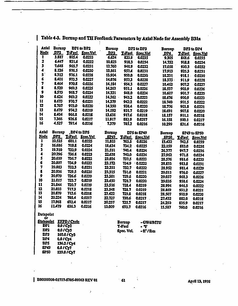
Table 4.3. Burnup and TH Feedbadk Parameters by Axial Node for Assembly B31a
AXIal Brnup DPI to DPNode pP2 TMel i me o
1 3.887 80.SA 0.02332 6A47 921.6 0.02323 7.648 965.7 0.02314 8.126 97.5 0.0230S' 8.312 976.1 002216 8A01 973.3 0.02277 tA64 970.8 0.0226t 8.520 969.3 0.02259 B573 968.7 0.0224
10 8.624 9692 0.022211 8A673 970.7 0.022112 t.707 973.0 O.22013 8.679 974.2 0m21914 3.404 966.8 0.0218IS 7366 926.8 0.021716 4527 797A 0.0216
Burcup
6.62410.82312.76013.5611390414.07614.184142631432114362143791435014.19213.638119177.379
Dn2toD}3T-Foel SmcVol
823.9 0.02359183 0.0234948.9 0.0232957A 0.0231959A 0.02309573 0I0228954.3 0.227951.1 0.0226948.0 O.2249452 0M239422 o022938A 0.0220931.7 0.0219917.6 0.0218883.9 0.021778S2 0.0216
urMnppP49305
14.75217.05817.9131823118.373184A6218S3718.60718.67618.74018.77618.69118.1S716.15810299
DP3toDP4TL-ef ERec.Vol
848.6 0.0235918. O.O234930.3 0.02329253 0.0231918.1 0.0230911.9 0.0228907.2 0.02279039 00226901.7 0.0225900.9 0.02239015 0.0222903.8 0.0221907.8 0.0220911.1 0.0218900.1 0.0217321.6 0.0216
AxialRode
I234S6799
1011121314IS16
Burnup ,DP4 to D5-DPS T'hde -ptLaol1053 681.1 0M2216.686 719.8 0.022419310 732.9 0.022420296 736.8 O22320.659 736.7 .02=220.807 734.9 O.22220.883 732.3 0.022120.936 7295 O0.22020.979 726.6 0.022021.017 723.7 0.021921.044 720.7 O.021921.033 7173 0.021820.879 712.6 0.021820.224 70SA 0.021717.968 692A . 0217IIA79 656.3 0.0216
Burnup DPS to SP49SP49 MiB±el &M
11.03 7035 0.022618.634 7342 0.022S21551 740A 0.022422z638 740.0 0.02423.024 737.S 002323.172 734.9 0.0222232S1 732.7 OA02223315 731.0 0.022123381 729.6 0M022023AS0 725.7 O.22023.516 728A 0.021923548 728.7 O.21923A22 729.8 0J21822.727 730.6 0.021720.237 72S.7 0021713.009 693.7 O0M16
urnuup SP49 to SF50NM&. TMel Sgee Vol
13A22 742S O23922.159 8830 0.023826377 947.7 0.023627.962 971.8 0.023428.576 981.6 0.023328.833 983.8 0.023128.952 981A 0.022929.011 976.0 0.022729.037 968.3 0.022629.035 958.6 0.022428.994 946W OM2228.869 9312 o0.02128507 910.9 0.022027A32 8820 0.021824:2S0 835.9 .0217IS587 760.0 0.0216
Datapointor
Statewoint EM/<!veLDPI OOICy2DP -0.OICy3DP3 160.0 1Cy3DWP4 0OIJy4DPS 136.21ICy4SF49 0.0 l Cy7S50 129.0 Cy7
Burnup -GWdftTrUTFued - 1SpecA VoL -1fP/lbm
61I BOOOOOO01717.570S.00063 REV 01 A4pril 13,1998

Table 4-3. Buup and Tl Feedback Parameters by Aslal Node forAssembly B31a. (Cont'd)
Axial Burkup MPSO to S5Node -Lt TLBel AneaVol
I 15.964 £24.9 0.02412 27354 948.1 0.02403 32.785 9773 0M384 34.675 9833 0.0236S 35346 980.1 OI.2346 35.591 973.9 OJ32
7 35.687 967.7 0.0230t 35.732 962.7 0.J2299 35.762 959.1 OIX227
10 35.7U3 956.9 OX2511 3S.782 9559 0.022412 35.699 9552 0.022213 35.343 952A 0IX22014 34.128 9405 0.0219IS 30.347 907.9 00218-16 19.794 £21.7 00216
Table 4-4. Burnup and TB Feedback Parameten by Aal Node for Assembly C25
AxialNode
1234.S67£9
10111213141s16
Burnup DP2 to DP3,.P3 WN SmceVol3.650 948.8 0.02476.077 1126.6 0.02457328 1199.8 0.02437.946 12273 0.02408271 1236.0 0.02388A60 12372 0M368.579 123S.9 0.02338.658 1234.0 0.02318.710 1232.6 .02291.73S 1231.7 OA2278.727 12309 0.02258.659 1228.5 0.02231.473 1220A 0.0221
8.014 11952 0012196.72 1229 0.02184.167 926.9 0.0216
BDrup DP to DP4DT-Tvel Svec.Vvl
7243 969.7 0245IIA92 1083.0 0.024413377 1110.6 0.024114.142 11102 0.02391A71 11032 0.023714.640 1096.1 0.023514.751 1090.8 0.023314.842 1087.S 0.023114.928 108S9 0.022915.012 10863 0.022715.090 1088.9 0.022S15.136 1094.1 0.022315.72 11OLS 0.022114.643 11O5A 0.022013.060 1083.1 0M188.359 9582 0Q2t17
9A7915.07617.S8418.616190SS192621937719ASS19.S1619.56619.59s19.568193781169716.SS110.S47
DP4 to DP5T-Foi SVol
791.0 0.0234t70.1 0.0233995 0.0231
908.7 0.030909.9 o029907 0.0227904.6 0.0226900.9 0.2258972 0.024$93A O28892 0.0221183.9 0.0220175.6 0.0219
860. 0.0218827.6 0.0217745.S 0.0216
Datapointor
Statepolut EFPD ICycleDP2 0.OICy3DP3 160.0 1Cy3DP4 0. OICy4DrS 136.2 ICY4S0 129.0Cy7SM 28231 C7
Runup MGWdAMTT-FueI *FSpec. VOL *fellbm
I BOOOOOOO-01717-570S.00063 REV OI 62 April 13,199S
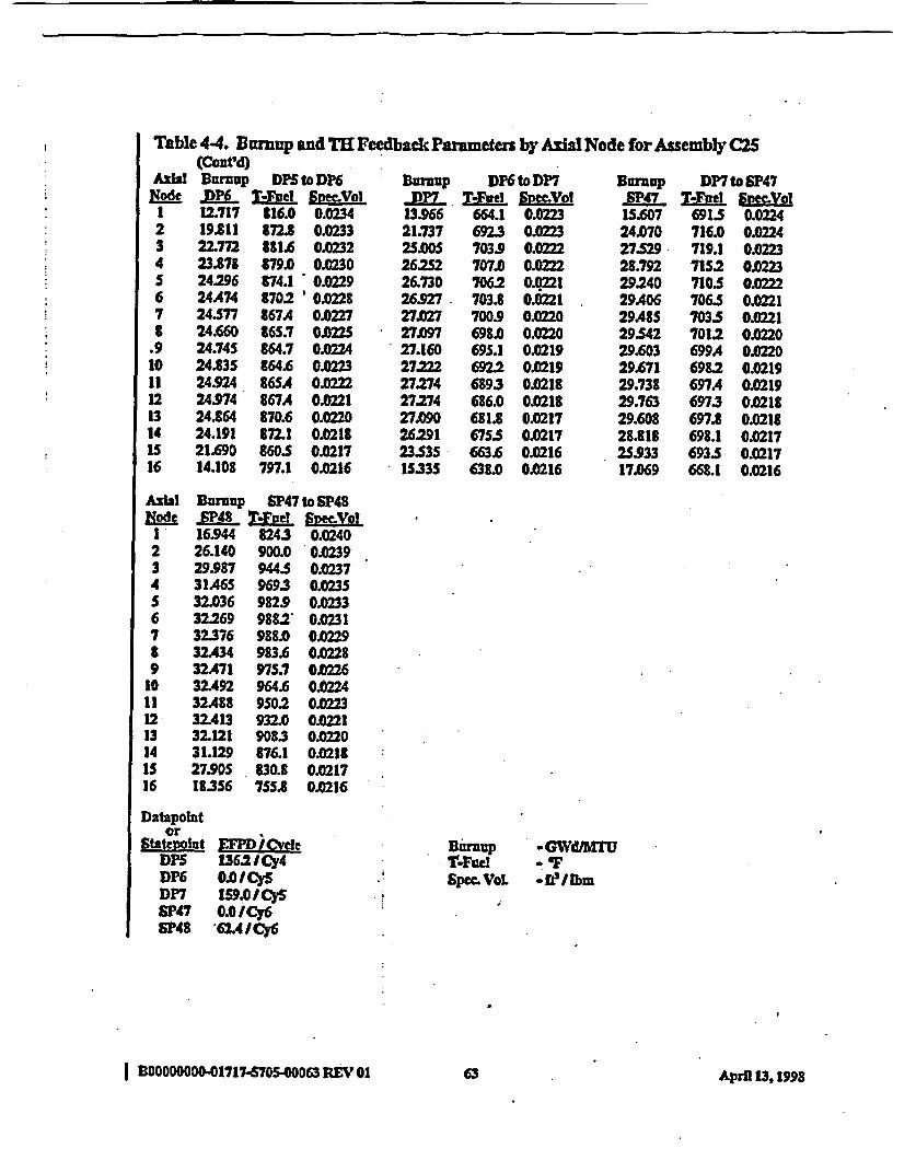
Table 44. Burnup and TXI Feedback Parameters by Axial Node for Assembly C25(Cont'd)
AxiJ! Burnup DPS to DK6 Bomp DP6 to DP7 Burnup DP7 to SP47Eode l)K T.-Fj l megVol -P7 ftd l JTj7SP47 T-Fjiel S;Mec
1 12.717 316.0 0.0234 13.966 664.1 002 15.607 691.5 0.02242 19.11 7.8 0.0233 21.737 6923 023 24.070 716.0 0.02243 22.772 581.6 0.0232 2S.OOS 7039 0.0222 27529 719.1 0.02234 23.878 879.0 O0230 26252 707.0 0.0222 28.792 71S2 0.02235 24.296 874.1 0.0229 26.730 706.2 0O02 29.240 7105 0.026 24A74 8702 'OQ228 26.927 703.8 0.21 29A06 706. 0.02217 24.S77 867.4 0.0227 27.027 700.9 O.M2 29A8S 703.5 O.2218 24.660 865.7 0.0225 27.097 698.0 0.0220 29542 7012 0.0220
.9 24.74S 864.7 0.0224 27.160 695.1 0.0219 29.603 699A 0022010 24.835 864.6 00223 27.222 692.2 0.0219 29.671 698.2 0.021911 24.924 865A 0.0222 27.274 6893 0M18 29.738 697A 0.021912 24.974 867A 0.0221 27274 686.0 0.0218 29.763 697.3 0.021813 24.864 870.6 0.0220 27.090 681.8 0.0217 29.608 697.8 0021814 24.191 872.1 0.0218 26291 675.5 0.0217 28.818 698.1 0.0217IS 21.690 860.S 0.0217 2353S 663.6 0.0216 25.933 693.5 0.021716 14.108 797.1 0.0216 IS33S 638.0 0.0216 17.069 668.1 0.0216
Axil
1234S6789
1011121314IS16
Burnup SP47 to SP48±P48 V-Fel SmzeVol
16.944 824.3 0.024026.140 900.0 O.3929.987 944.5 0.023731A65 969.3 0.023532.036 982.9 0.023332269 9882' 0.023132.376 988.0 0.022932A34 983.6 0.022832A71 975.7 0.632.492 964.6 0.022432.488 950.2 0.022332A13 932.0 0.022132.121 908.3 0.022031.129 876.1 0.021827.9p5 830.8 0.021718.356 755.8 0.0216
Datapolitor
Statevoint E: PD ICgelDPS 136.2 /Cy4DK6 0.0ICySDP7 1S9.I/CySSP47 0.0 /Cy6SP48 621AICy6
Bumupd-l
Spec. VoL
-GWdMTUi
-fWlbm
I B00000000.01717-670S00063 REV 01 63 Akpril 13, 1998

Table4-. Btmup andTl FeedbackParameters byAxialNode forAssembly D
AIa Bunnup DP4 to DPSEgLe P TL-itl 3t mVo1I 2A75 864A 0.02382 4.140 1016.1 OA2373 4.961 1081.1 0.02354 S.329 110SA 0.0234S SA90 1112.7 0.02326 5S57 1113A 0.02307 5.S80 1111.7 0.02298 S580 1109A 0.02279 S566 1107.0 0.0225
10 S5.40 1104.7 O.022411 SA97 1101.7 0.022212 SA20 1096.6 O.0Q2113 5270 108S.7 0.022014 4.946 1059.0 O.02I115 4.189 990.9 0.021736 2496 82SA 0.0216
Bursup Dr5 to DP6
6.0709.613
11.711.58311.7501180611.83311.5911892I1S3311.978I01211.97011.63710.3616.573
T-Lfel Smex:ol8912 0.023;995. 0023
10183 0.02351019.6 O.2341015.6 0023210123 0.02311010.4 0.022910099 002810105 0.02261012.1 O.022510152 O1X2231019.9 0.02221025.9 0.02201028.0 0.02191006.6 O0.2188862 0.0216
Brnaup
10.56716.49018.9451986320209203432039520A1420A1620A0320.36520.26920.01319.27917.095IOS18
DP6toDP7
95S.7 0.02461070.5 0.024411102 0.02421119.6 0.0240118.1 0.023711123 0.0235IOS.0 0.0233097.5 0.0230
10903 0.022810835 0.022610765 0.02241068.2 0.02231056.6 0.02211036.7 0.0219992.7 0.0218874.6 0.0216
Axial Burnup DP7 to SP47Node 04_. TLfetle SIecVolI IS.666 962.8 0.02462 23590 1039.5 002443 265S8 IS2.6 0.62414 27.S12 10462 01X239S 27.798 1036A 0.02376 27.881 10282 0.03S7 27.914 1022.2 0.0233t 27.943 10183 0.02319 27.982 1016.1 OX29
10 28.033 101S.5 0022711 28.088 1016.7 0.022S12 28.119 1020.0 002313 28.011 10252 O0.02114 27363 1028A O.220IS 24827 1013.7 0.021816 16568 924.0 0.0217
Datapointor
St tewlint EX\ Chde -DP4 0.0ICy4DPS 136.2 1Cy4DP6 0.0I CySDP7 159.0/CySSF47 0.0 ICy6SP48 62A/Cy6
BDrup SP47 to $P48-FP48 ZESl g2pym l16375 726.8 0.024125.032 803.8 0.024028.939 936.1 0.023830.2S6 986.2 0.023730.712 1006.9 O023S30.88 1016.0 0.023230.9S 1017.9 0.023031.007 1015. 0.022831JD31 10082 0.022731.041 997.8 002231.030 983.6 OX2233D.9S9 964.9 0022130.702 939.6 0.022029.827 903.6 0.021826.906 8502 0.021717.899 764.8 0.0216
Baruup -GWdAMTUT-Focd * FSpecVoL -fellbm
I BO00O0.01717-670500063 REV 01 64 'April 13t998

Table 4-6 Burnup and TH 1eedback Parameters by AxI Node for Assembly D14
AXWNode1
234S6
.789
101112-1314is16
Buranup DP4 to DP5DU M~et SpmVol
3.568 989.5 0.02SO5.868 1181. 0.02487.004 1261.9 OM457.S21 1292A 0.02437.758 1302.7 0.02407.868 1304.7 0.02377.915 1303.7 O0357.930 1301.7 0M327.924 1299. 0.02307.899 1297A 0.022870 1294.6 0.02257.755 12893 0.02237.561 1276.9 02217.132 1245S 0.02196.103 1162.1 O.S83.707 948.6 0.0216
Burnup DP7 to EP47A4L M-el SeL
14.002 805.6 0.023321.618 858.2 0.0224.740 868.6 0.3125.857 864.5 O.22926.238 8S7A 0.022826.373 851.2 0.022726A40 646.6 0.022626A97 843.3 O.22526.563 8412 0.022426.641 840.0 0.022226.72S $40.0 0.022126.781 841.2 0.M2026.689 843.3 0.021926.03S 843.7 0.021823A73 831.0 OJD217lSA30 775.S O.216
Burnup DPS to DP6DP68.635
13A444ISA3816.1S416i41216.52016.58716.65016.72016.80116.88716.95816.93316534114.609.619
T-eal Euec.VoT1002.6 0.02SO11153 0.024811473 0.02451149.0 0.02421144.7 0.02401141.1 O0.2371139A O1X23511393 0.02331140.6 0.023111433 0.02281147.7 0.022611545 0.02241163.2 0.02221168.0 0.02201141.2 0.02181001.9 0.0217
Bump
11.0321728619.98421.03421A4S21.61821.70521.76421.81S21.86121.89521.88221.71321.03718.76112.107
DP6toDP7T-Fuel f;meo
771.S 0.0232t452 0.0231872.5 0.0230B80.6 0.0229880.1 0.0228876.3 0.0227871A O.022866.4 0.0224161.5 O.223856.9 0.0222852.0 0.02218463 0.02208383 0.021982S.0 0.02187983 0.0217728.8 0.0216
Axhia
123456789
1011121314IS16
Burnup SP47 to SF43_iP48 Me2l Snec.vol15326 827.8 0.023923.669 9029 0.023827.148 943.S 0.023628AS4 964.1 0.023S28.947 974.9 O.23329.146 9793 0.023129.243 979.0 0.022929.304 975.0 0.022729.351 967.8 0.22629388 957.5 0.022429A06 944.1 0.022229369 926.9 0.022129.145 904.8 0.022028.296 875.1 0.02182sA04 830.8 0.021716.681 7562 0.0216
Datapointor
Statepoint EFŽD /CycleDP4 .OI Cy4DPS 1362 ICy4DP6 0.I/CySDP7 159.01CySSP47 O.O ICySP48 62AICY6
BDnarupT-FueISpe. VoL
aGWdMTU-tF* e/lbm
I DOOOOOOOO-01717-5705-00063 REVrO3 6S April M3 1998.

I Table 4.7. Bamup and TH Feedback Pammeters by Axi Node for Assembly D14a
AialNode
Ii34s6789
10111213
'14IS16
Burnup DP4toDP5.M Vt~e1 Smeof '
3568 989.5 00)25S68 1181.0 0.02487.004 12619 0O457.521 12924 0.02437.7S8 1302.7 0.02407.868 1304.7 002377315 1303.7 O357930 1301.7 00373924 1299.5 0.02307.899 1297A 0.87US0 1294.6 0.257.SS 1289.3 0.237561 1276.9 0.0217.132 124S 0.02196.103 11621 0.02183.707 948.6 0-0216
Surnup DPStoDP6JDP6 T.Fel Soe.Yo8.635 1002.6 0.00
13444 1115.3 0.0248ISA38 1147.3 0.024516.154 1149.0 0.024216A12 1144.7 0.024016.S20 1141.1 0.023716.587 1139A 0.023S16.650 11393 0.023316.720 .1140.6 0.023116.801 11433 0.022816.887 1147.7 0.022616SS8 1IS45 0.022416.933 11632 00216.534 1168.0 0022014.860 11412 0.02189.619 1001.9 0.0217
Darnup DP6 to DP7
11.032 771.S 0.023217286 B45.2 0.023119994 872.5 0.023021.034 880.6 0.022921A4S 880.1 0.022821.618 8763 00221.705 871A OA02221.764 866A 0022421.815 861.5 0.022321.861 856.9 OX22221.95 8520 0.022121.882 8463 0.022021.713 838.3 0.021921.037 825.0 0.021818.761 7983 0.021712.107 728.8 0.0216
NodI1
234S67.891011121314is16
Bumup DP7 to SP47-SP47 T-IBlel Stee Vi
14JDOS 805.6 0.023321.622 85B.2 0.023224.742 868.6 0.02312S.858 864.5 O.02926.239 857A 01X22826374 8Si.2 O.022726A41 46.6 0022626A98 U433 O.2526564 841.2 0.22426.643 840.0 0.022226.726 840. 0.02212U783 8412 0.O22026.691 8433 0.021926.038 843.7 0.021823A79 831.0 0.021715A3S 775.S 0.0216
Burnup SP47 to SP48SP48 T.Fued Soe~oS5442 8489 0.0242
23.864 932.7 0.024027AIS 984.1 0.023928.756 10103 0.023629252 1021.S 0.03429A41 10242 O0X03229.522 10214 0.023029564 1014A 0.022829591 1004.1 0.J22629.607 990.7 0JD22529.607 974A 0.022329.556 9SS.I O229326 931.8 0J022028A81 9023 0.021825594 8S83 0.021716.826 778A 0.0216
DUnMup "GWdAMJ
Spec VVoL .tlibm
Datapointor
Statepofnt E I JCycleDP4 0.OICY4DPS 136.2 ICy4DP6 .OICySDP7 159.0 CySSP47 0.0 IJCyGSP48 6u4/ Cy6
| -BOOOOO-01717-5705000 REV 01 66 April 13,1998

I Table 48. Burmup and TH Feedback Parameters by Axial Node for Assemby D17a
AXWMile123456789
1011121314is16
Barnup DP4 to DPS
3.856 1017.7 0226.310 1217.6 0.02507.510 1303A 0.02478.017 1334A 0.02448223 13433 0.02418298 1343.3 0.02398.311 1340.0 0.02368293 1335. 0.023382S4 1331.1 0.02318.196 1326A 0.2288.116 1320.9 0.02268.000 13133 O.2247.802 1300.0 0.02227.387. 1268.7 0.022063S3 1184.1 0.02183.878 965.5 0.0217
guruupDP69265
14A.4816.67917A2417.65417.72317.75317.7821782017.86717.92517.97117.95S17M6615.79210.175
DPS to DPK
10224 0O2541147.1 .02521187.1 0.02491192.2 0.02461189.5 0.02431186.6 0.02401185A 0.0237118S.9 0.23S1187.6 0.0232190.8 0.02301195.7 0.022712032 OX2251213.8 0.02231219.1 O.02201184.6 0S2181026.8 0.0217
DusmnpDP7L
11.88418.71121.73222.8822329923.44723.5032352923.S4623.55623.55523.5142332922.6332020313.021
DP6 to DP7TeFuel SpoVvI
719.8 O.235870.9 0.0234902.0 0.0232912.2 0.02319125 0.0229909A 0.0228904A 0.0227899.1 0.022894.0 .0224889.0 0.0883.8 0.02218775 OA2O868.1 0.0219851.9 0.0218
23.7 0.0217750.9 0.0216
AshINode1234s6789
10111213141s16
Buraup DP7 to SP47-SP47 meFu figmyof15.176 832A 0.023523.S48 890A 0023427.077 904.2 0.023323312 899.1 0.023128A697 390.9 0.023028.805 884.0 0.022928.841 879.0 0.022728.67 875.6 0.022628.904 873MA OX22S28.953 872.4 0.022329.011 872.6 0.02229.050 8742 0.022128.954 876.8 0.02202289 877.6 0.021925.563 8642 0.021716.850 8033 OM0216
Burnup SP47 to SF48_3iP48 T-F el ISyDO'
16.511 827.8 O.024125S659 909.1 o024029.630 961.7 0.023831.114 992.6 0.023631.638 10082 O.023431.821 1014.6 0.023231.889 1014.8 0.023031.918. 1010A 0.022831.930 1002.3 0.022631.931 990.7 O1X025311914 975.6 Ol.t2331.848 9956 0.022131.60S 931.1 0.022030.722 896.7 0.021827.631 846A 0.021718.192 76S.1 OX2t16
Bumup -(GWITVFWd -' FSPe VoL -feII
Datapointor
ktatevotnt EWPD CycleDP4 0.0 ICy4DP5 13M2IICy4DP6 0.0/CySDP7 159.0ICySSP47 0.0/Cy6SP48 62AICy6
Ibm
| B00000000-01717.570S-D0063REVO0 67 April 13, M8

Table 4-9. Bumup and TR Feedback Parameters by Axhl Node for Assembly D21
Axial
fdI
23456789
1011121314Is16
BurnUp DP4 to DPS.ML T-FideFpecyol2322 846.6 0.02373.9D2 991.8 0.02364.688 1054.7 0.02345.044 1078.9 0.02335202 1086.7 0.02315269 1087.8 0.02295.294 1096.S 0.2285.297 1084A.. 0.02265286 1082.3 0M0225S264 10802 0.02235.22S 1077. 0.0222S.ISS 1072.7 00221S.014 1062.2 0.02194.706 10362 0.02183.984 971.0 0.02172369 812.1 0.0216
Burnup DP5 to DP6_ME T-fteI Sg il
5.716 8739 0.02379M91 975A 0M0236
IOA91 999.1 0.023410.988 10003 0.023311.154 997.1 023111212 994.1 OX23011241 992A 0.022811268 -9920 0.0Q2711301 992.6 0.022611342 994.3 O0.22411388 9973 0.022311A23 1001.9 0.022111385 1007.7 0.022011.069 1009.8 02199.849 988.9 .012176234 871A O1D216
Buraup
10.19516.05118.57619.57619.98120.15420.2362027720.298203012027720.18919.93319.18516.9310.846
DP6 to DP7del SVoI
961.9 0.02481084.6 0.02461132:2 0.02441146.0 0.02411146.2 0.023911412 0.02361134A OX23411275 0.02311120.9 0.02291114.6 0.02271108.2 0.02251100.5 0.02231088.9 0.02211067.S 0.02191019.0 0.0218892.1 0.0217
Node1234S6789
1011121314is16
Burnup DP7 to SP47hEL T.iel Spen~Yl1S313 9703 0.0247
23.266 OS23 0.024526380 1067A 0.024227AS1 1061.8 0.024027.808 1051.8 0.023827.935 10433 0.023S28.000 10373 0.023328.0S7 1033.5 0.023128.121 1031A 0.022928.195 1031. 0.02728272 1032A O.22528321 10362 0.0228.224 1041.8 0.022227.567 104S.1 0.022024982 1029A 0.021t16.629 93S2 0.0217
Bumrnp SP47 to SP48_SPi48 T-Iftel Spec.Val16.780 U48.6 0O4125518 931.7 0.024029.019 976A 0.023830293 999.S 0.023630.762 1011.0 0.023430.947 1014.6 0.023231.033 1012 0.023031.081 1P06.8. 0022831.111 9973 0.022631.129 984.8 0.022531.127 969.1 0.022331.069 949.2 O.22130.830 925.9 OX22029.972 894.0 0021827.046 8472 0.021717.981 767.7 0.0216
Bo-nap *GWdJMTU
SPe cVoL -feIlbim
B 0 0 0 0 0 0 0 0 . 0 1 7 7 -5 7 0 5 . . o~6 8 'E 0 1A r l 1 9
Datapointor
Statepoint ME1PDLrcleDP4 0.OICy4DM 136=2/CY4DP6 00/CySDP7 159.01CySSP47 0.OICY6SP42 62.4 ICy6
I B0OOOOO00-01717tO05SO0O3REV OI Aprl 13,1V998
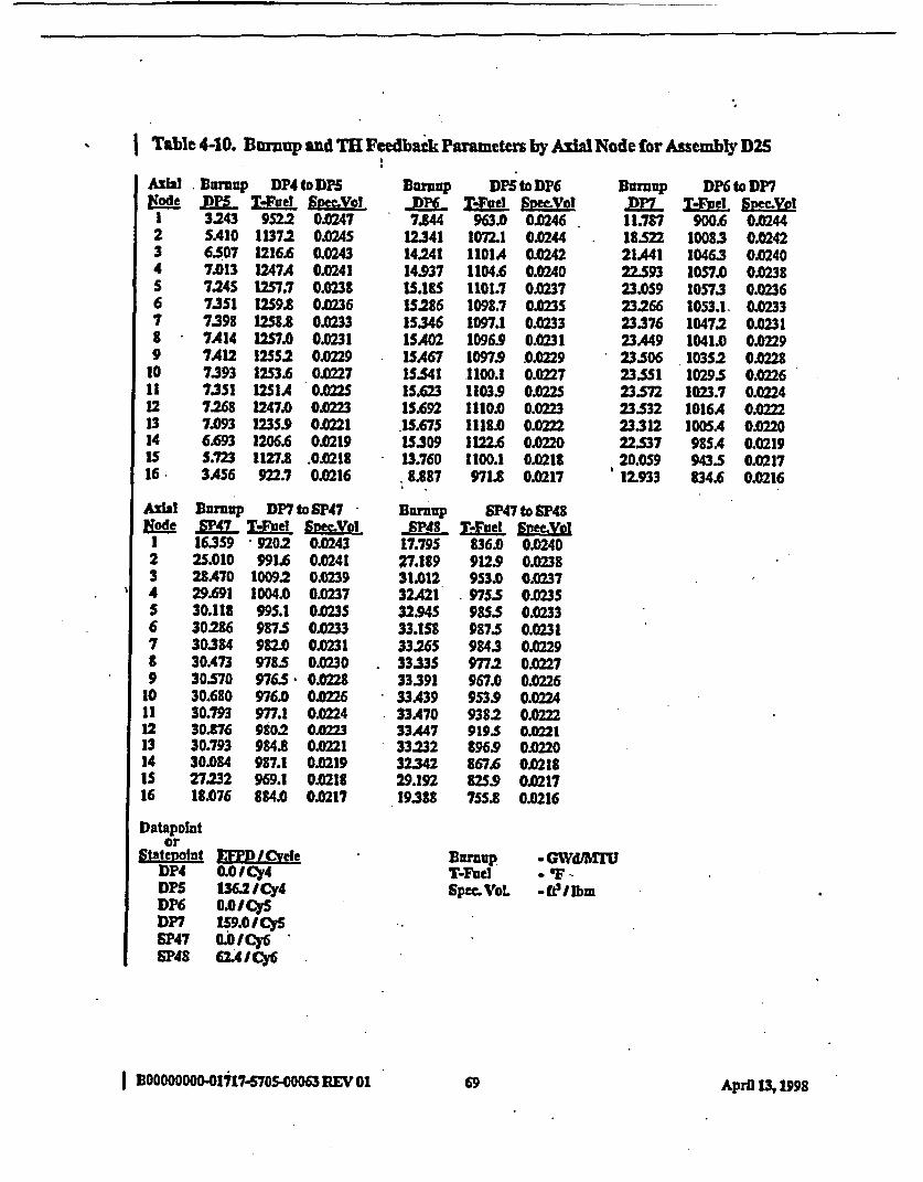
Table 4-10. Bmrup and TH Feedback Parametern by AIa Node for Assembly D25
Axial Burnup DP4 to DPSNode DPKL LiFWl Spec1 3.243 9522 0.02472 SAI0 1137.2 0.02453 6507 1216.6 0.02434 7.013 1247A 0.0241S 7.245 1257.7 0.02386 7351 2W59.8 0.02367 7.398 12S8.8 0.02338 7414 1257.0 0.02319 7A12 12552 0.O229
10 7393 12S3.6 0.022711 7351 12SIA O.02S12 7.268 1247.0 0.022313 7.093 1235.9 0.022114 6.693 1206.6 0.0219IS 5.723 1127.8 .0.021816 3A56 922.7 0.0216
Bhmup DPS to DP6Tite Symd(eViol
7.844 963.0 0.024612341 1072.1 0.024414241 1101A 0.024214937 1104.6 0.024015.18S 1101.7 0.023715.286 1098.7 0.023SIS.346 1097.1 0.0233ISA02 10969 0.023115.467 1097.9 00229IS.541 1100.1 0.022715.623 1103.9 0.022S15.692 1110.0 0.0223.15.675 1118.0 0.22215309 1122.6 OX22013.760 1100.1 0.02188.887 971.8 0.0217
Bornup SP47 to SP48SP48 T-Fvel SymVel
17.795 836. 0024027.189 912.9 0.023831.012 9S3.0 O.23732421 975.5 0M3532.94S 985.5 003333.158 987.5 0.02313326S 9843 0.022933335 977.2 0.022733.391 967.0 0.0226
* 33A39 953.9 022433A70 9382 01322233447 919.5 022133.232 896.9 O.02032L342 867.6 0M1829.192 825.9 0.021719388 755.8 0M16
Bmup
11.78718.52221A4122.59323.059232662337623A4923.50623SI23.57223532233122253720.05912.933
DP6toDP7TI del SnecVol
900.6 O.24410083 0.024210463 0.02401057.0 0.023810S73 0.02361053.1. 0.023310472 0J2311041.0 O29103S2 O.02810295 0.02261023.7 0.02241016A 0.02221005A Ol 22098SA 0.0219943.5 0.0217834.6 0.0216
Axial&ode
123456789
10111213141516
Burnup DP7 to SF47P47 Te- e Vol
16.359 9202 0.024325.010 991.6 0.024128A70 10092 0.023929.691 1004.0 0.023730.118 995.1 0.023530:286 987.5 O.23330384 982.0 0.03130.473 978.5 0.023030.570 976.5 O.02830.680 976.0 022630.793 977.1 O0.02430.876 9802 O.022330.793 984.8 0.022130.084 987.1 0.021927232 969.1 0021818.076 884.0 0.0217
Datapointor
Stateonet EFPD ICycleDP4 0.01 Cy4DPS 136.2 1Cy4DP6 LOCIJySDP7 1S9.0/CySSP47 OICy6 -SP48 62L41Cy6
BurnupT-FuelSpec Vol
GWdlMru-F..Itellbm
I BOOOO0000-P01G77.S-00063 REV01 69 April 13, 1998

f Table 4-11. Buraup and TH Feedback Parameters by Axial Node for Assembly D28
A1ihNode
1234S67£9
1011121314lS16
umnup DP4 to DP5 -
DMS WnFel SymxV613.198 945.2 0.02495.S81 1150.6 0.02476M870 1246.3 0.024S7441 1281.9 O.2427.687 12932 O.2407.793 1295. 0 .277.833 1293A 003S7.842 129.9 .02327.831 1288A 0.02307.803 1286.1 0012287.7S3 t2833 0.022S71i53 1278A OX2237A81 1267.0 0217.073 1237.8 0.02196.72 1157A 0.02183.692 9462 0.0216
Burnup DPS to DP6U M.el SMV'
7.714 949.6 0.024812.723 1070.7 0.024615056 1120.0 0.02441SS 11318 0.M4216.158 1131.0 0.023916255 112835 023716305 11269 0.023416352 1126.7 0.023216A08 1127.7 0.023016A76 1130.0 0.022816.54 1134.1 0.022616623 1140A 0.22416.609 1148.9 0.022216.244 S14.0 0.022014.635 1128.9 0.02189A81 9933 0.0217
B~upDP710377169301994121.06221A6621Mi6121Ai9321.74021.78021.81721.84421.82721.6S920.98918.71St052
D6 to DP7T-Tel swetol
793.8 0.0233867.8 0.02328903 0.0231896.0 0.023089S.7 0.022B892.4 0.0227888.1 0.0226883.5 0.02258789 0.0223874A 0.0222869.7 0.0221863.7 0.02208S4.7 0.0219838.9 0.0218808A 0.0217734.1 0.0216
AiwNode
I234S6789
tO111213141S16
Burnup DP7 to SP47R4A T-fte SmVol13567 818.9 O23421524 871.9 0.023324919 879.9 0.023126.087 875. 0103026A462 869.2 01X22926587 863.7 0.022826.647 859.6 0.022626.700 8S6.8 OM02226.765 85S.1 0.022426.943 854A 0.022326.929 8S4.8 OJ.2222690 856A OQ221265903 858.6 0.021926.24S 8584 0.21823.638 844.0 0.021715A86 781.9 0.0216
Bunup SP47 to SP48SP48 T-Jbed gme.Vel
15.043 8595 0.024223.798 941A 0.24127S86 986.1 0.023928969 10102 0023729A471 1023.6 0.023S29.670 1029A 0.023329.76S 1029.6 0.023129823- 1025A 0.022929.866 10175 0.022729.899 10062 0.022529.912 991A 01X22329.869 972.2 0.022129.636 947A 0IXX2028.762 9133 0.021925.790 8633 -0.021716.84 779.2 0.0216
Barnup - GWd/MTUT-Fued - 'FSpec VoL -fel/bm
Datapointor
Ebitevwint MFD CyeleDP4 0.0 I Cy4DPS 136.21Cy4DP6 0.OICySDP7 159.0/CySSF47 0.0/Cy6SP48 62.4ICy6
II
I BODOOOOO-01717.6705.00063 REV 01 70 Apra 13 1998
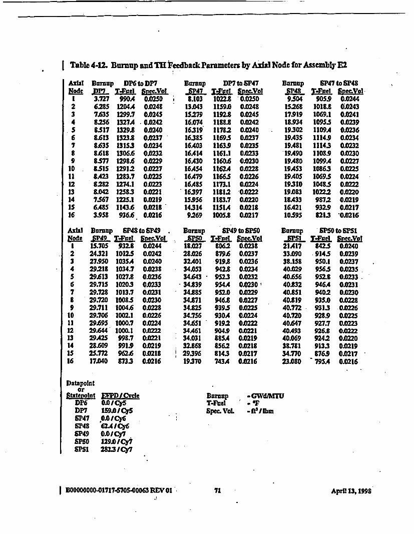
Table 4-12. Burnup and TH Feedback Parameters by Axl Node for Assembly E2
AxIal Burnup DP6 to DP7Node DP7l T4jid Spec-Vol
1 3.27 990A 0.02S02 628S 1204A 0.02483 7.63S 1299.7 0.02454 82S6 1327A 0.Q242S 8.517 1329.8 O.0O406 8.613 1323.8 0.02377 8.63S 131S.3 002348 8.618 1306.6 0.02329 8.5 1298.6 0.0229
10 8M1S 12912 0022711 8.A23 1283.7 0.012 8282 1274.1 0022313 8.042 12583 0.022114 7.567 122S.1 0.0219IS 6.48S 1143.6 0.021816 3.958 936.6C 0.0216
Axil Burnup SP48 to SP49ode jLP49 VWel S LI IS.705 932.8 0.02442 24.321 1012.5 0.02423 27.950 103S.4 0.02404 29.218 1034.7 O2385 29.613 1027.8 0.02366 29.71S 10203 0.02337 29.728 1013.7 0.02318 29.720 1008.5 0.02309 29.711 1004.6 0.0228
10 29.706 1002.1 0.022611 29.695 1000.7 0.02412 29.644 1000.1 0.013 29A2S 998.7 0022114 28.609 91.9 0.021915 2S.M 962 0.021816 17.040 873.3 0.0216
If
Burnup DP7 to SP47SP47 TIel SpneVol8.103 1022.8 0.02SO
13.043 1159.0 0A24815279 1192.8 0.024516.074 1188.8 0.024216319 11782 OQ401638S 11695 0.023716A03 11639 O.23S16A14 1161.1 0.023316A3D 1160.6 0.023016AS4 1162A 0.022816A79 1166.5 0.022616.48S 1173.1 0.022416397 11812 0.022215.956 1183.7 O.2014314 IISIA 0.02189269 1005.8 0.0217
Burcup SP47 to SP48A_48 T-Foel S;mVol9.504 905.9 0.0244
15268 1018.8 0.024317.919 1069.1 OQ24118.934 1095. 0.023919302 1109A 0.023619A35 1114.9 0.023419A81 11143 0.023219A90 1108.9 0.023019A80 1099.4 0.022719AS3 10863 0.022S19AO5 1069.5 0.22419310 1048.5 0.022219.083 10222 O.022018A33 9872 0.021916A21 932.9 OM1710595 8213 0.0216
Burnup SF50 to SP51
21A17 842.5 0.024033.090 914.5 0.023938.158 950.1 0.023740029 956.5 0.03S40QS6 952.8 0.023340.2 946A 0023140.851 9402 0.023040.819 935.0 O.22840.M2 9313 022640.720 928.9 0.D22S40.647 927.7 0.022340A93 926.6 0.022240.069 9242 0.022038.781 9133 0.021934.770 876.9 0J21723.080 ' 795A 0.0216
Burnup SP49 to SF50_|0 VFOe.l Svec.Vol18.Q27 8062 0.023828.026 879.6- 0.023732A01 919.8 0.023634.053 942.8 0.23434.643 952.3 0.023234.839 9S4A 0.0230'34.88S 9520 0.022934.81 946.8 0.022734.825 9395 0.022534.756 930A 0.022434.6SI 9192 0.022234A61 904.9 O.22134.031 885A 0.021932.868 8562 0.21829396 8143 0.21719370 743A 0.0216
Datapointor
Stbtepolnt EFPFDICvdeDP6 0.0ICySDP7 159.0OCySSF47 0.0 ICy6SP48 62A4 I Cy6SF49 0.0ICy7SF50 129.0 /Cy7SCM 2823ICY7
Buarup -GWd/MTUT-Fuel - FSpec. VoL -ft'llbm
BOOOOOOOO-01717-670S-00063REVo1A9n1 April A3 1998
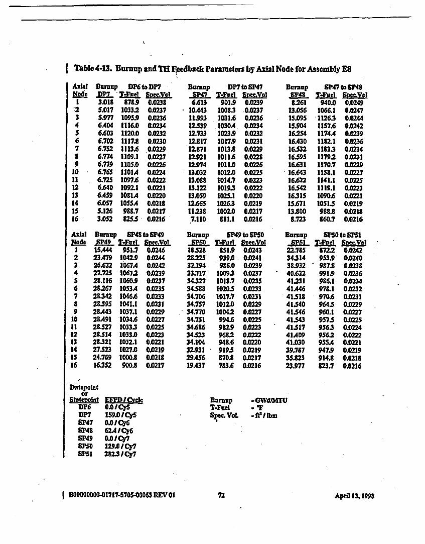
Tabie 4-I3. Bumup and TR Eeedback Parameters by Axil Node for Assembly ES
NodeI'234S6789
10111213141s16
AihAilPJEode
I23456789
1011121314IS16
Sunup DP6 to DP7.DP7 * Wivel SLmel3.018 8789 0.0238£.017 10332 0.0237
S.977 1095.9 0.02366.404 1116.0 0.02346.603 1120.0 0.02326.702 1117.8 0.02306.752 1113.6 002296.774 1109.1 0.276.779 1105.0 0026.765 1101A 0.0246.72S 1097.6 0.02226.640 1092.1 0.02216.459 1081A 0.02206.0S7 IOSSA 0.02185.126 988.7 O.02173.052 825.5 0.0216
Bumup SP48 to SP49SF49 T4Fuel &pe
1SA44 951.7 0.04623.479 1042.9 0.024426.622 1067A 0.024227.725 10672 0O.03928.116 1060.9 0.023728267 1053A 0.023S28:342 1046.6 0.023328.395 1041.1 0.023128A43 1037.1 0.022928A91 1034.6 O022728.527 1033.3 0.02221514 1033.0 0A321321 1032.1 0M2127.523 1027.0 0.021924.769 1000.8 0.021116352 900.8 0.0217
Dumup DP7 to SP47,Smu T--e1 spmVol6.613 901.9 0.0239
IOA43 100.3 .023711.993 1031. 0.03612.539 1030.4 0.023412.733 1023.9 0.02322.817 1017.9 0.0231
12.71 1013 0.022912.921 1011.6 0.022812.974 1011.0 0.022613.032 1012.0 OK22S13.081 1014.7 OA.02313.122 10193 0.013.059 102S.1 0.022012.66S 10263 0.021911.238 1002.0 0.02177.110 881.1 0.0216
Bumup SP49 to SF50_,- ;0 T-Flld smV olIB528 8519 0.024321S22S 939.0 0.024132.194 986.0 0.023933.717 10093 0.023734327 1018.7 0.023534.58 1020.5 0023334.706 1017.7 0M3134.7S7 1012.0 0.022934.770 10042 0.M2734.751 994.6 0.022534.686 982L9 .022334.S23 968.2 0.22234.104 941.6 0.022032.931 919.5 0.021929AS6 870.8 O21719A37 783.6 0.0216
Burmup SP47 to SP48RS_4 Mel Sid Vol
.261 940.0 0.024913.056 1066.1 0.024715.095 1126. 0.024415904 1157.6 0.4216.254 1174A 0.023916.430 1182.1 0.03616.532 1183.3 0.023416595 1179.2 0.023116.631 1170.7 0.0229
*16.643 IIS8.1 0.022716.622 1141.1 0.O02516.542 1119.1 0.022316315 1090.6 0.022115.671 10515 0.021913.100 988.8 0.02188.723 860.7 0.0216
Bunmup SPSO to SF51M -T.FuIel Snec.Vol
22.785 8722 0.04234314 953S9 0.024038.932 - 987.8 0.03840.622 9919 0.023641.231 986.1 0.023441A46 978.1 003241518 - 970.6 .023141.540 964.5 0.22941.546 960.1 0.022741.543 957.5 O.22541517 9563 0.02441A09 956.2 002241.030 955A 0M2139.717 947.9 0.02193523 914.1 0.021823.977 823.7 0.0216
Datapointor
Ststtvofnt Em I lCvdeDP6 0.01CiDP7 159.0/CySSP47 0.0I Cy6SP48 62AICy6SP49 0.0ICy7
PSO ./ Cy7PSF 282.3 /Cy7
Bursup WGWd/MTUT-Fud aorSpec VoL -ft 3 [Ibm
I B0ooooooo01717-57S-00063 REV 017 72 Aprifl 13, I§98
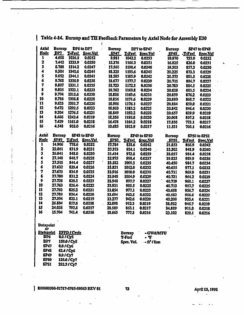
I Table 4-14. Bumup and TH Feedback Parameters by Axial Node for Assembly E10
AxhlNod~e
123456769
10*11121314is16.
AxilNoel
1234S6.789
10111213141516
Burnup DP6 to DP7.pn lVPv Spec-Vol4.608 1036.5 0.02527A42 1233.9 0.02508.788 13142 0.02479.384 1340.6 0.02449.02 1344.1 0.02419.768 1338.9 0.02389.807 1331.1 0.023S9.80S 1323.1 0.02339.774 131S.6 0.02309.716 1308.8 0.02289.623 1301.7 0.02269A72 1292.S O.2239204 1276.5 0.02218.666 1242A4 0.02197A29 1161.0 0.02145S48 953.0 0.0216
Burnup SP48 to SP49SP49 Tnei 60ecMVol
14.906 778.6 0.023222.861 831.9 0.023126.041 848.0 0.023027.148 848.7 O.0282751 8444A 0.022727.632 839A 0.022627.673 834.9 0.022527.700 8312 0.022427.728 828.3 0.022327.763 826A 0.022227.793 8252 0.022127.780 824A 0.022027594 523.1 0.021926.804 817.6 0.021824.036 797.S 0.0217IS.704 741A 0.0216
Buroup DP7 to SP47-SP47- T.Yvel 6poo9.981 1042.2 0.0253
15376 11663 OSI17560 1198A 0.02481832S 119S. 0.02451858 118S.9 0.024218.677 1177.7 0.0239i8.723 1172.3 0.023618.762 1169.8 0.023418.806 116.6 0.023118.856 1171.6 0.022918.906 1176.1 0.022718933 1183.2 0.022518849 11922 O.02221a.356 1195. p22016.478 11642 0.021810.68S 1013.9 0.0217
BDurnup SF49 to SP50-"0 T-Yvef symy.of
17.784 838.6 0.024227.373 924.1 0.024031A14 972.8 0.023932.975 998A 0.023733582 10093 0.023533MI8 1012.0 0.023233.916 1010.0 0.023033.948 1004.9 0.022933.948 997.7 0.022733.921 9885 0.022533.8S4 977.1 0.022333.694 962.S 0.022233277 942.6 0.022032.098 912.3 0.021928S89 863.1 0.021718.66S M.3 0.0216
Burnup SP47 to SP48SP48 .T-FodeI S2eLol10.0 705.0 0.023216.825 826.0 0.023119303 857.3 0.023020.225 873.3 0.022920573 881.5 0.022820.715 884.7 0.022720.785 8845 0.022520.828 881.5 0.022420.859 8762 0.022320.880 868.7 0.022220.884 859.0 0.022120.842 546.4 0.022020.657 829.9 0.021920.008 8073 0.021817.856 773.1 0.021711531 70S.1 0.0216
Burnup SP50 to SF51-gmP5 T-YFad Sameu~l
21.85 866.9 0.024233302 948.9 0.024038.057 984.4 0.023839.82S 989.9 0.023640A50 984.7 0.023440.5SS 977.1 0.023240.711 969.9 0.023140.721 9642 0.022940.719 960.1 0.022740.713 957.7 0.022540.688 956.7 0Q2440582 9566 ' 0.022240200 955A 0.022138.932 946.7 0.021934.889 911.0 O.0I223.102 820.1 0.0216
L-
Datapolntor
Statevohut EMP ICVeleDK6 0.0ICySDP7 119.I CYSSp47 0.01Cy6SP48 62AI C6SP49 0.CY7SN5 1290/Cy7SPS1 2823M /C7
BurnupT-FueISpecf. VoL
0GWdIMT- F-fe/Ibm
I BO000000-01717-5705400063 REV 01 73 Azpril 13, 1998
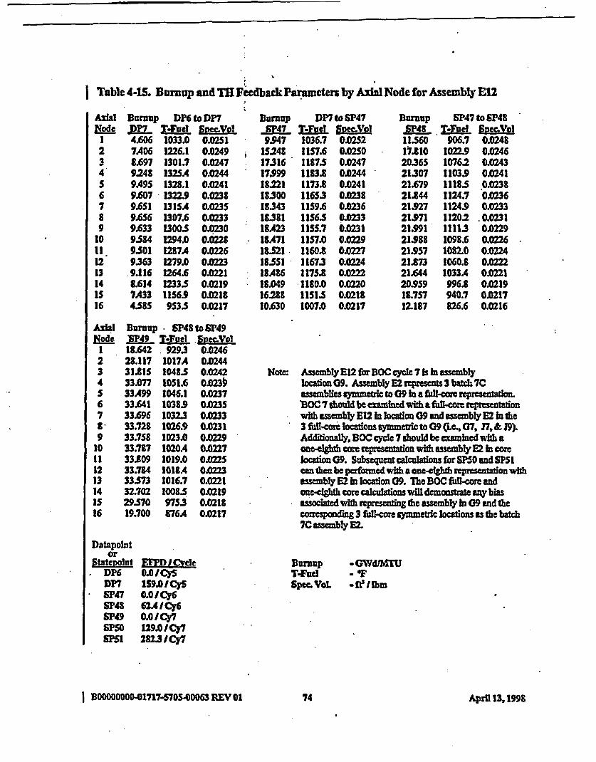
Table 4-15. Burnup and TR Feedback Parameters by Axial Node for Assembly E12
Niode1234S678910
121314IS16
Burnup DK6 to DP7T~e1 svo
4.606 1033.0 0.02517A46 1226.1 0.02498.697 1301.7 0.02479248 1325A 0.02449A95 1328.1 0.02419.607 1322.9 0.02389.651 1315. 0.023S9.6S6 1307.6 0.02339.633 13005 002309.584 1294.0 0.02289.501 1287A 0.02269363 1279. 0.229.116 1264.6 O.2218.614 1233.5 0.02197A33 1156.9 0.02184.58S 953.S 0.0217
Burnup DP7 to SF47_gP47 TWOOe 2=3x%1o9.947 1036.7 O.252
IS248 1S176 0.02S017316 1187.5 0.024717.999 1183.8 0.0244I8.221 1173.8 0.024118300 116S.3 0.023818343 I1S9.6 0.023618381 11S6.5 O.23318.23 11S5.7 0.0231I1A71 1157.0 0.0229183521 1160.8 0.027185SI 1167.3 O.02418A86 1175$ 0.022218.049 1180.0 0.022016288 115.5 0.021810.630 1007A 0.0217
BUruup SP47 to SF4815P48 T.Fbdel S pVo11560 906.7 0.024817.810 102I29 0.024620365 10762 0.024321307 11039 0.0241211679 11185 0.023821.844 1124.7 0.023621.927 1124.9 0.023321.971 11202 O.023121.991 11113 0.022921.988 1098.6 0.022621.957 1082.0 0.022421.873 1060.8 0.022221.644 1033A 0.022120.959 996.8 O0.21918.757 940.7 0.021712.187 926.6 0.0216
II
Axial Burup SP48 to SP49Node E49 -ludj Sgec.Vog
1 18.642 929.3 0.02462 28.117 1017A 0.02443 31.81S 1048.S 0.02424 33.077 1051.6 0.023kS 33A99 1046.1 O.2376 33.641 1038.9 0.02357 33.696 1032.3 0.02338 33.728 1026.9 0.02319 33.758 1023.0 0.0229
10 33.117 1020A 0.022711 33.809 1019.0 00212 33.7U4 1018A 0.0213 33573 1016.7 0.022114 32.702 1008.5 0.0219IS 29.S70 975.3 0.021816 19.700 876A 0.0217
Datapointor
Statewo~nl IM I veleDP6 0.0 ICySDP7 159.0 1C$SF47 0.0 /Cy6SP48 624I CyS
SP49 0.0I Cy7SPF5 129.0 ICy7SF51 282.3J Cy7
Note: Assembly E12 for BOC cycle 7 is hI assemblylocation 09. Assembly E2 represents 3 bach 7Cassemblies symmetric to 09 in a fuil-core representation.BOC 7 should be examined with a Mi.=oe represntaonwith assenbly E12 In location 09 and assebly E2 hin the3 full-corlocaions symmetic to C9 (Le, 07, J7, & Js)Addionally, BOC cycle 7 should be examined with acameighth core reprsuentato with asembly E2 in corelocation C9. Subsequenticalculations forSF50 and SP51can then be performed with a one-eighth representafion withassembly E2 in location C9. The BOC full-cowe andone-eI&hth core calculations will demonsuate ny bisassociated with rqprsenting the assembly in G9 and thecornsponding 3 fuil-core symmetric locatons as the batch7C asembly E2.
Burnap -GWd&hOrUTVF - 'Spec.VaL -felbm
| BOOODOOO-01717-570S-00063 LEV 01 74 April 13, 1g9S
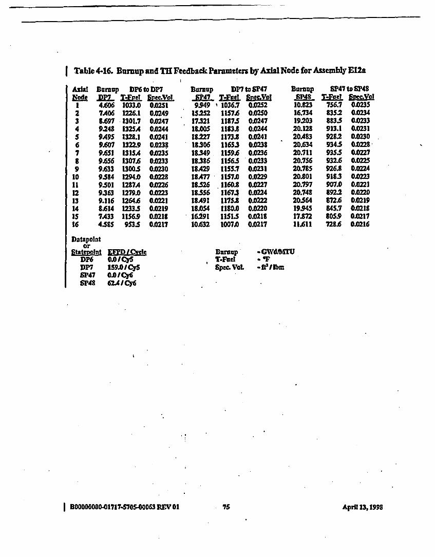
I Table 4-16. Bumup and TH Feedback Parameters by Axial Node for Assembly E12a
AIWtEode
1234S6789
1011121314is16
Burnup DP6toDP7&P_ T-L2el gnSVDl4.606 1033.0 002517A06 1226.1 0.02498.697 3301.7 0.02479.248 132SA C 002449A9S 1328.1 0M419M607 1322.9 0.02389.651 131SA 0.02359.6S6 1307.6 002339.633 13005 0.02309584 1294.0 009.501 1287A 0.02269.363 1279.0 0M239.116 1264.6 0.02218.614 12335 0M02197A33 IIS6.9 0.02184.585 9535 0.0217
Surcup DP7 to SP47SP47- M-el SEgMVol9.949 ' 1036.7 0.0252
t5.252 1157.6 0.02S017321 1187.5 0.024718.00S 1183.8 0.024418227 1173.8 0.024118306 11653 0.023818349. 1159.6 01.23618386 IIS6.S 0.023318.429 IISS.7 0.023118A77 1157.0 0022918.S26 1160.8 0.022718.5S6 11673 0.022418.491 1175.8 0.022218.054 1180.0 On22016.291 IISS 0.021810.632 1007.0 0.0217
10.82316.7341920320.12820A8320.63420.71120.75620.78520.80120.79720.74820.56419.94517.87211.611
SP47 to SP487'-Fve! 60MV0l756.7 0.0235835.2 0.0234883.5 .0233913.1 0M319282 0.0230934.5 0M28935.5 00227932.6 0.0225926.8 0.02249183 0.0223907.0 0.01892.2 0.0220872.6 0.021984S.7 0.0218805.9 0.0217728.6 0.0216
DatapoIntor
Stateucint £EF'.L -xvkDP6 0.0/ICySDP7 159.0/ICySSP'47 0.0 I Cy6SP48 62A ICy6
BumpI T-FcVLSp=c VaL
* GWd/KMU
-ft 3IIbm
I BDOOOOOOO-01717.5705.00063 REV 01 7S AprU 13, 199S

I Table 4-17. Burnup and T'H Feedback Parameters by Axd! Node for Assembly E14
Node123456789
10111213141S16
NodeI234S6789
1011121314Is16
Buruup DP6 to DP7IZD TuefI Snym.Vol4.087 984.9 0.02486.696 1171.7 OA.2467.945 1245.8 O.0448.501 1270.7 0.02413.766 1275.8 O0.039
8.902 1273.0 0.02368.974 1267.8 0.02349.010 12622 0.02319.021 1257.1 0.02299.005 12S2.7 O.2278.956 1248.1 0.02258.849 1241.5 m0238.624 1228A 012218.128 11982 0.02196.948 1121A O.02184212 921.9 0.0216
Burnup * SP48 to SP49.P49 TIFeod Snec.Vo11.93 702.6 O.O22S18.506 742.9 O1X22521.203 7513 0.022422.161 7S1.0 0.02422A97 747.7 OXZ2322.625 743.8 O22222.692 740.3 0.022222.74S 7372 0.022122.799 734.8 O.X22D22.8S8 732.8 0.022022.912 731.3 0.021922.930 729.9 0.021822.799 7282 0.021822.1SS 7243 0.021719.831 714.0 0.021712.840 675.9 0.0216
Burnup DP7 to SP47,47 TVFWe SyVl8.911 1002.0 0.0249
:13.908 11198 0.02471S.933 1150.8 0.024416.640 1149.1 0.24116.902 1140.9 0.023917.023 11335 0.023717.107 1128.6 0.023417.18S 1126.1 0.023217.267 112S.6 0.023017353 1127.1 0.022817A37 1130.9 0.022617A97 11372 0.224
^ 17A446 11452 OA.22216.997 11483 0.022015213 1118.0 0.02189.766 978.3 0.0217
BUnup S49 to PS0"X5 T--Foel SpmVol
14.650 841.8 0.024423277 957S. 0.024326.950 1015.6 0.024128393 1042A 0.023828S89 1054.0 0.023629250 1057. 0 03429374 105S.0 0.023229A34 1049.6 0.023029AS7 1041.7 0Q2729A47 1031.7 0.2629394 1019.1 0.022429248 1003. 0.0228863 9812 0022027.794 948.8 0.021924.663 8942 O0M01715.940 800.1 0.0216
Burnup SP47toSF48-SP48 TFte! Specmol9393 670.1 O.025
14.709 712. 022416922 735.5 022417.741 749.1 OM318.6S 755.9 02318218 7583 OQ22218314 757.8 O.022118391 7553 022A118A61 7513 0.022018525 746.0 0.021918578 7393 021918.593 730.9 0.021818.479 7203 0M1717.938 7063 0.021716.000 685.9 0.0216102SS 64S.8 0.0216
Durnup SP50 to SPS1V1 TJthel Spec-Vol
18.511 8712 0.024429.SI7 978.1 0024234.032 1013.9 0.024035.70S 10202 0.023836330 1015.6 0.23636563 1008.0 OQ3436!6S4 1000.9 0.0336.695 99ss2 0023036.720 9912 O.022B36.737 9889 0.A22636.732 9882 0.022436.64S 9883 0.022336297 987.1 0.02213S.128 977.6 0.021931MAI 9443 0.021820.6S4 848.9 0.0216
Datapolntor
statepoint EFPD /(>elDP6 0.0ICy$DP7 159.0O CySSF47 0.0 ICy6SP48 . CM /ICy6SF49 0.I Cy7S5 129.0/Cy7SPF51 23 /CY
Buruup*T4FUeSpec. VoL
-GWd1U- 'IF- WI Ibm
I BD0000000-01717-570500063 REV 01 76 April 13, 1998.
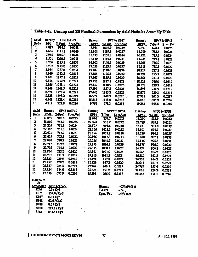
I Table 4-18. Burnup and T} Feedback Parameters by Aial Node for Assembly E14a
AihINoe
1234S6789
1011121314IS16
AiWKode
I23456789
1011121314iS16
Bumup DP6 to DP7-D7 T-Ie1 P.Elyot4.87 984.9 0.02486.696 t171.7 OA02467.94S 124S.8 0.02448.S01 1270.7 0.02418.766 127S.8 0.02398.902 1273.0 0.02368.974 1267.8 02349.010 1262.2 0.02319.021 1257.1 0.02299.OOS 12527 0.02278.956 '1248.1 01022S89.49 1241.S O0238.624 1228.4 0.02218.128 11982 0.02196.948 1121.4 0.02184.212 921.9 .0J216
Burnup SP48 to SP49-S49 T-Tef S3neVol11.895 702.6 0.022518.509 742.9 0.022521205 751.3 0.022422.162 751.0 O.22422.498 747.7 0.022322.625 743.8 O022222.690 740.3 0.22222.742 7372 0.022122.796 734.8 0M2022.8S4 732.8 0.022022.907 7313 .021922;923 7299 0.021822.792 728.2 0.0218225147 7243 0.021719824 714. OD21712.836 675.9 0.0216
Eurnup DP7 to SP47SP47 WN TFueI SecV8911 1002.0 0.0249
13.908 1119.8 0.24715.933 1150.8 024416.640 1149.1 0.024116.902 1140.9 0.023917.023 1133.5 0d23717.107 1128.6 .0J23417.1S 1126.1 0.023217267 1125.6 0.023017.353 1127.1 OK22817.437 1130.9 O.02217.497 11372 0.022417A446 11452 0.02216.997 1148.3 0.0220IS213 1118.0 0.2189.766 97B3 0.0217
Burnup SP49 to SFS5SM5 S--Fnet Smno-Vol
13.644 759.7 0.024322.398 9182 0.024226.597 994.6 OM24028.166 10252 0.023828.796 1038.1 01)23629.076 1042.0 O.03329216 1040.9 0.023129293 1036.7 0.022929335 1030.3 0.022729.347 1021.9 OQ22S29.316 10113 0.022429.194 997.3 0.022228.829 977.3 O0.02027.767 946.1 0.021924.625 8912 0.021715.893 796.4 00216
EUnup SP47 to SP48L48 TMFoe Svec.Vol
9.393 670.1 0.022514.709 7124 0.022416.922 73.5 0.022417.741 749.1 0.022318.06S 755.9 0.022318218 7583 0.022218314 757.8 0.022118391 7553 O02118A61 7513 0.022018.525 746.0 0.021918-578 7393 0.021918.593 730.9 0.021818A79 7203 0.021717.938 7063 0.021716.000 685.9 0.021610.2S5 645.8 0.0216
Burup "so0 to SPS1-Ml T--ftet SOMW
16274 83.9 0.024227.789 9633 0.024133231 993.0 0.023935.091 996.1 0.023735.756 990.S 0.023536.008 982.7 0.023336.116 975.5 0.023136.176 970.0 0.022936.224 9662 0.022736266 9642 0.022636.289 963.7 0.022436.233 9642 0.0235.915 963.7 0.022134.769 95SA 0.021931.068 9243 0.021820368 834.1 0.0216
Datapointor
StateDownt EFP};I CycleDP6 0.01 CySDP7 IS9.0ICySSP47 0.01 Cy6SP48 62 I Cy6SP49 0.0 ICy7
F0 129.01 Cy7S5 1. 282W3/Cy7
Bimrup -GWd/UTUT-Fud -eFSper YoL -fNIJbm
I BOOOOOO10-0171M7-00063 REVO1 77 Apra 13, 1998
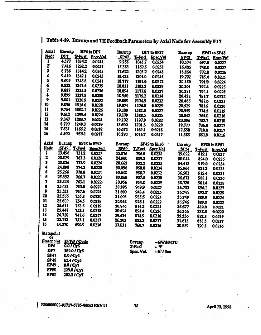
Table 4-19. Burnup and TR Feedback Parameters by Axial Node for Assembly E17
AzUIN~ode
I234S6789
1011121314Is16
AzWNode
1234S6789
10II12u314is16
Bunuap DP6 to DP7
4377 1034.2 002S37.416 1232.2 0.02SI8.788 1314.2 0.1249A10 1342.1 0.024S9.699 1346.8 0.419.832 1342.5 00399.887 13353 0.02369199 1327.8 0.339.881 1320.9 0.02319.336 1314.6 0.02289.754 1308.1 0112269.C12 1299A 0.02249.347 1283.7 0A2218.799 12493 0.02197331 1166.2 0.02184.600 956.1 0.0217
Burcup SP48 to SP49MP_4L T-Feel S mVol
13A96 721.2 0.022720.829 763.3 M022623.t26 773.9 O22624.l98 774.2 0.022525.266 770.8 Ol0242S.392 766.7 002232SA444 763.1 CAM2225A81 760.0 O2225.521 757.6 0.212SS66 75S.8 0.02225.609 754.5 0.02192S.C11 7S3.S 0.02192SA47 752.1 0.021824.710 747.6 021722.113 733.1 0.021714370 690.9 0.0216
lurznup DP7 to SP7*P47 ftEel SipcVol9.9S6 1043.7 0.0254
IS383 11693 .025SI17.622 1203.2 0.024818A28 1201.0 0.024518.717 1191.6 P0.24218.t31 11832 0.023918.894 1177.8 0.0237189S0 117S2 0.03419.009 1174.9 0.023219.074 1176.8 0022919.139 11813 .022719.179 1188.5 OJ2519.102 1197.9 02218.600 1201.8 0.022016.675 1169.1 0.021810.790 . 1016.7 0.0217
Durnup SNP49to PSO-SM M -el SymetVl15.876 796.0 0.023824.900 8893 0.023728.66S 932.2 0.023S30.096 9SO.0 0.023430.648 956.7 0.023230.866 9513 0.023030.956 954.8 O1229303995 949.9 0.022731009 943A O.0531.003 93S53 0022430965 926.1 0.022230.846 . 9142 0.022130A94 898A 0.022029.434 874.9 0.021826202 83S2 0.021717.031 760.7 0.0216
Burnup SP47 to SP48,SP48 T-Fue Sfo;cVoT10S74 697.0 0.022716A40S 748.8 0227
18.864 772.8 0.022619.792 785A OX27520.150 7919 0.022420301 794A 0.022320381 794.1 OX22320.438 791.7 OX22220486 717.6 O0.22120.529 781.9 0.022020359 774.S 0.021920548 765.0 0.021820396 752.7 0.021819.777 736. 0.021717.650 710.8 0.02171138S 661.9 0.0216
Burnup SP50 to SF51.M T-Vel SnMVol
19.092 8t2.1 0.023730.044 894.0 0.023634A13 919.0 Ol23435.966 9213 0.023336302 91SA 0.023136.3 98.1 O236.720 901A O236.733 896.1 0.022736.741 8923 0.0236.749 889.9 002436.746 889.0 0.022236.677 889.0 0.022136366 888.6 0.022035256 882.8 0.021931.615 8583 0.021720.859 7903 0.0216
Datapolutor
Statepoint ETDI CircleDP6 0.0/ICySDP7 159.0I CysSP47 0.0 ICy6SU48 62AICY6Sp49. 0.O1Cy7SF50 129.01 Cy7SSI 2823/Cy7
Suniup -GWdMTlUTFueI VL O
SPMeVGL *flt3 bm
BOOD000001717-S70S.00063 R1EV .01 78 April 13, 1998

Table 4-20. Buumup and TH Feedback Parameters by Axial Node for Assembly E17a
AxINode
1234S6789
1011121314IS16
Nqode1234S6789
1011121314iS16
Durnup DP6 to DP7pP7 TVrod See.Vol4.S77 10342 0.02S37A16 1232.2 0.02SI3.788 13142 00248
9A10 1342.1 0.024S9.699 1346.3 0.02419.3M2 13425 0.02399.887 1335.3 0.02369.899 1327.8 0.02339.881 1320.9 OX2319.36 1314.6 002289.7S4 130L1 0.02269.612 1299A 0M249.347 1283.7 0.02213.799 12493 0.0219
7.S31 1166.2 0.02134.600 956.1 0.0217
Burp SP48 to SP49-SP49 T-Fuel Vol13492 7212 01X22720.822 7633 0.022623.818 773S 0.022624.890 7742 O225258 770.8 0.02242S383 766.7 0.02232SA36 763.1 0.022225A73 760. 0 O02225S.513 757.6 0.022125.SS8 75S.8 0.022025.601 7S4.S O.1925.603 7535 0.2192SA40 7521 O.21824.703 747.6 0021722.106 733.1 0.021714365 '6909 OM16
BDurnp DP7 to SP47_JE47 TF SpeeVol9.956 1043.7 0.0254
15383 1169.5 0.02SI1762 12032 0.024818A28 1201.0 0.024518.717 1191.6- 0.024218.831 11832 0.023918.394 1177.8 0023718950 11752 0.023419.009 1174.9 0.023219.074 1176.8 0022919.139 31813 0.022719.179 1188.5 0.0M19.102 11979 0.022218.600 1201.8 0.022016.67S 1169.1 0.021810.790 1016.7 0.0217
BDrmup S49 to tF5.0 tvel Svmol
16.301 840.7 0.024225328 931.6 0.024129263 986.0 O023930.829 1012.1 0.023731AS4 10233 0.023S31.710 1026.S 0.02333180 1024.6 0.023131.864 10195 0.022931.874 012.1 0.22731.856 1002.6 0.022531.797 99M 0.022331.646 975.6 0.022231243 955.0 0.022030.103 924A 0.021926.742 8739 0.021717362 785.S 0.0216
umVp SF47 to SP48SP48 T-Faelt SymViot1OS74 697.0 01)22716.405 748.8 0.0227188J64 772.8 0.022619.792 785A 002220.150 791.9 OJX22420301 794A OX22320381 794.1 0.022320A38 791.7 O0.22220A86 787.6 O.02120329 781.9 0.022020.5S9 774.5 0.0219203S48 765.0 0.021820396 752.7 0.021819.777 736.0 0.021717.650 710.t 0.02171138S 661.9 0.0216
Burnup SF50 to SPSI_"I T-gel SPVol
20318 87S3 0.024331302 9599 0.024136.030 994.8 0.023937.831 1000.7 0.023738A83 995.5 0.023S38.708 987.8 0.023338.780 980.5 0.02313X803 974.7 0.022938.812 970.6 0.022738.816 968.1 0.022638.600 967.1 .022438.703 967.1 0.2238334 965.3 0.022137.099 956.7 0.021933.186 921.8 0.021821.881 830.1 0.0216
Datapointor
Statepolot KIlM/W>eLDP6 0.0/ICySDP7 1S9.0OCySSP47 0.0/ Cy6SP48 62A4ICy6SP49 0.0 ICySF5 129.0/ Cy7SPSI 2823 ICy7
Bornop -GWd/MT-Fe a OFSpec=VoL - f Ibm
I | 00000000.01717-57500063 REV 01 79 AprD 13,IM99
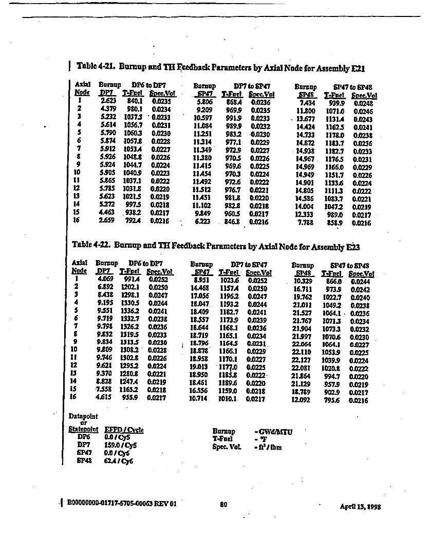
Table 4-21. Burmup and T1 F1eedback Parameters by Axial Node for Assembly E21
Ax1Node
I234S6789
l011121314ts16
Burnup DP6 to DP7
2.623 840.1 0.02354379 980.1 0112345232 10373 0.0233S.C14 1056.7 0.0231S.790 1060.3 0.02305.874 10S7.8 0.02285.912 10S3A 0.0227S.926 1048. 0.02265.924 1044.7 00245.90S 1040.9 OO235.86S 1037.1 0.0s.ns 1031.8 0.02tO5.623 1021.S 0.0219S272 997.S 0.02184A63 -9382 0.02172.6S9 792.4 0.0216
BUrnUP DP7 to SF47SP47 M-Fel SP=VI5.806 868A 0.02369209 969.9 0.023S
IO.S97 991.9 0.023311.084 989.9 0.023211.2SI 983.2 0.03011.314 977.1 0.022911.349 972.9 O0.22711.380 9705 0.0226IIAIS 969.6 O.22S11A54 9703 0.0224IIA92 972.6 0.022211512 976.7 .0o221I IASI 981.8 0.022011.102 982.8 0.02189.849 960.5 0.2176:223 846.8 O216
BRamp SP47 to SP48.PAg_ T--jiel ftec.Vol7A34 939.9 0.0248
11.800 1071.0 0.024613.677 1131.4 0.024314.424 11625 0.024114.733 1178.0 0.023814.872 1183.7 0.023614.938 11827 0.023314.967 11763 0.023114.969 1166.0 0.022914.949 1151.7 0.022614.901 1133.6 0022414.805 1111.3 OX22214.586 1083.7 0.022114.004 1047.2 0.021912333 989.0 0.02177.788 858.9 0.0216
Table 4-22. Burnup and TH Feedback Parameters by Axial Node for Assembly E23
AXWNode
I234S6789
10111213141s16
Burnup DP6 to DP7DP7 VWF frnecyo?4.069 991A 0.02526.892 1202.1 0.02508438 1298.1 0.02479.19S 1330.5 0.02449351 13362 0M419.719 1332.7 0.02389.798 13262 0.02369.832 13193 0.02339.834 1313.3 0.02309.809 1308.2 0.02289.746 1302.8 0.269.621 12952 0.02249370 1280.8 0.0221882 1247A 0.021973SS 1165I 2 0.02184.61S 955.9 0.0217
Burnip DP7 to SP47SP-A T--Fvel - ftmVol8.9SI 1023.6 O.052
14A468 1157A 0.02S017.056 11962 0.024718.047. 11932 0.024418A09 1182.7 0.024118.J7 1173.9 0.023918.644 1168.1 0.023618.719 1165.1 0.02341.796 116435 023118.878 1166.1 0.022918.9S8 1170.1 0.022719.013 1177.0 0.022518SS50 118S.8 O.022218A61 1189.6 O.220-16356 1159.0 0.021810.714 1010.1 0.0217
BDnup SP47to SP48-SP48 T-Fad Bpeyo10329 866.0 0.024416.711 973S 0.024219.762 1022.7 0.024021.011 1049.2 0.023821327 1064.1 0.023621.767 1071.3 0.023421904 10733 0.023221.997 1070.6 0.023022.064 1064.1 0.022722.110 10S3.9 0.022S22.127 1039.9 0.022422.081 1020.8 O.022221.864 994.7 0.022021.129 957.9 0.021918.789 902.9 0.021712.092 795.6 0.0216
Datapointor
Statevoint EM I -CycleDY6 0.OIICySDP7 IS9.0/CySSP47 0.0 ICy6SP48 62A4ICy6
BurnupT-FuelSpec. VoL
aGWdlb= U-F401bm
,I Bo0000000-01717s7s-POo00063REV0o 80 April 13,1998

Table 4-23. Burnup and TH Feedback Parameter by AxIal Node for Assembly E25
AxhlNode
I.234
6789
101I121314IS16
Burznp DP6 t DP7.P7 T-YFel SnmVol-3A637 945.5 0.024S6.0S 1126.8 002447291 1202.1 0.2427.880 1228.6 0.02398.171 1234.0 0.02378321 1231A 0.02358A01 126.5 0.02328A44 1221A 0.02308A62 1216.9 0112288AS6 1213.1 00268A18 1209A 0.02248.32S 1203.9 0.02228.118 1192A 0.02217.650 1164.1 0.02196529 1090.8 0.02133.942 899A .0.M16
Burmup DP7 to SP47,3pP47 M-el Se7.983 69.6 0.0245
12.617 1084SA 0.024314.606 1112.6 0.0241IS359 1110.0 0.023915.650 1101.1 0.023715.784 10933 0.023515.871 1088.2 0.023315.950 1085A 0.023116.031 1084.6 0.022916.116 1035.7 0.022716.199 1038.9 0.022516259 1094.6 0.022316214 1102.0 0.0221IS.790 IIOS.4 0.022014.123 1079.8 002189.056 9493 0.0217
BUrnUp SP47 to SP48.SP4 T.Fuel yecVolel
£852 762.1 0.023414078 841.7 0.023316.420 885.8 0.023217381 911.0 0.023017.791 9242 0.022917.991 929.9 0.022818.110 930.6 0.022618.197 927.7 O.22518267 922.1 0.022418.322 913.8 O.222183S6 902.8 0.022118342 888.6 0.022018.186 869.6 0.021917.588 843.1 010218IS.618 802.0 0.02179.968 722.6 O0X216
AshRodd
I234S6789
to11121314IS16
R1 DuMup SP48 to SP49e ,P49- VFW Svm~oI
13.103 802.3 0.023420359 869.2 0.023323.756 886.4 0.023124.970 886.8 0.02302SA21 881.7 0.022925.600 876.0 0.022725.693 870.9 0.02262S.763 866.7 0.022S25833 863.6 0.242S.04 861A O.02325.968 860.0 0.022125S98S 8S9.1 0.02202S.824 857.6 0.02192S.064 8S2.1 0.021822AOS 8313 0.021714S27 7642 0.0216
Burnup SP49 to SPSO,SO T-ftel SeVOl16216 867.0 0.024425.427 958.1 0.024229512 10089 0.024031.182 10335 0.M3831874 1044.1 00123632.178 1046.7 0.023432324 1044A 0.023232399 1038.9 0.02932A435 1031. 0.2732A438 1020.9 O.O22S32.395 1008S 0.022432:2S1 992.6 0.02231.844 971.3 022030.674 939.7 0.021927.233 887A 0.021717.660 795.2 0.0216
Durnup SPSOto SF1.Ml TFbel SrVel20593 893. 0.024431.783 979.0 0.024236599 1012.8 0.024038A69 .10185 0.023839.178 1013.2 0.023639A448 1005 0.023439557 9982 O.03239.611 992.4 0.023039.647 988A 0.022839167S 986.0 0.022639.678 9852 0.022439394 98s3 0.022339226 9842 O.22137.966 9753 .0J21933.969 940.0 0.021822.404 842.9 0.0217
Dstapointor
Stgsteoint MMF / l(VeleDP6 0.0ICySDP7 1S9.o/CySSP47 .0 /Cy6SP48 62AICY6SP49 0.0 ICy7SIO 1290 I Cy7
PS1 2823 ICg7
Bnrnup -GWdWUlT-FueI - 'FSpwc VoL -ftillbm
*I BOOOOOOOO10717-9605*0063 RVOA1 81 Apri 1, 1998
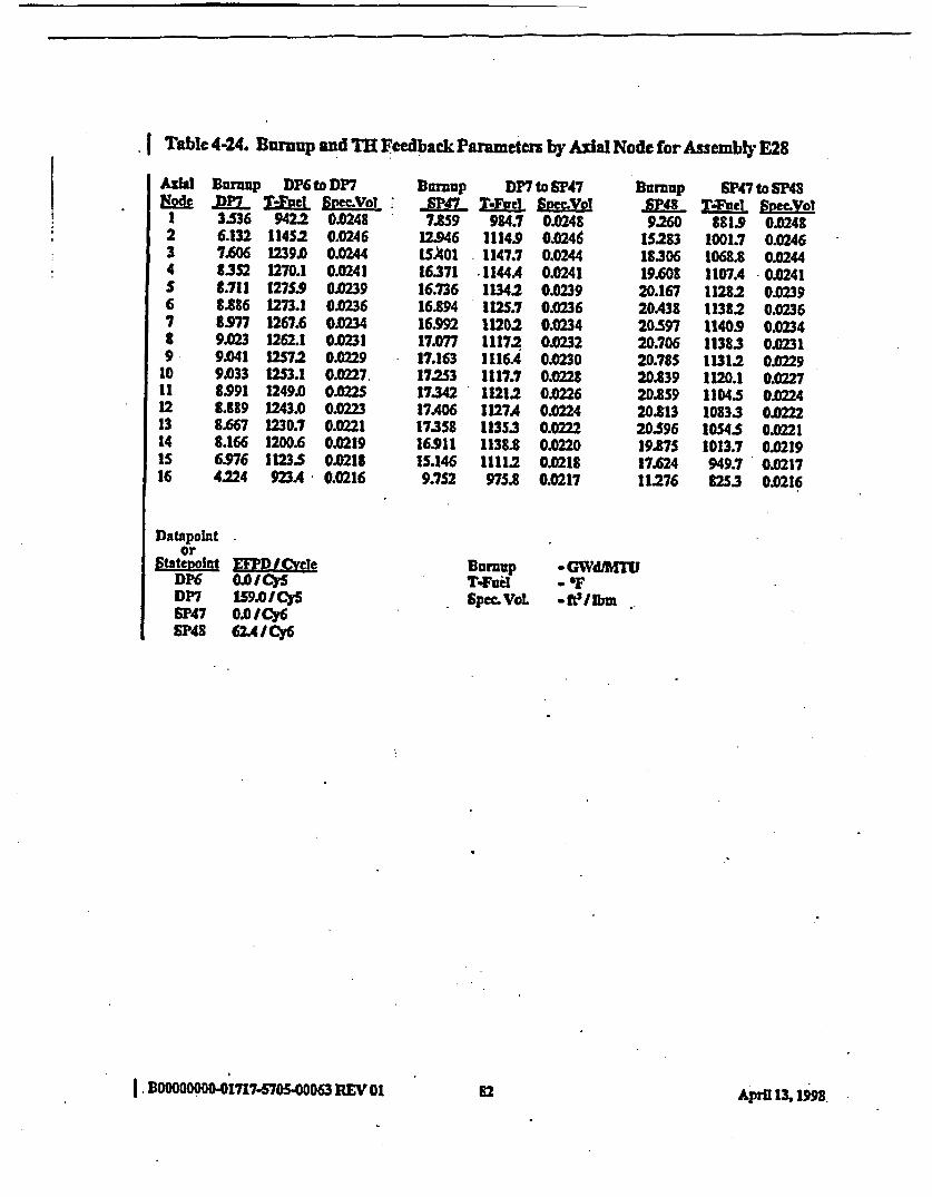
| Table 4-24. Burnup and TH Feedback Parameten by Asa Node for Assembly E28
AIW&ode
1234S67t9
1011121314is16
Burnup DP6 to DP7ZM T-Taue mecvoy3536 9422 0.02486.132 114S2 0.02467.606 1239.0 0M448352 1270.1 0M418.711 1275.9 0.0239B.886 1273.1 0.02368.977 1267.6 002349.023 1262.1 0.02319.041 12572 0.02299.033 1253.1 0.02278.991 1249.0 0.08.389 1243.0 0.02238.667 1230.7 0.02218.166 1200.6 0.02196.976 11235 0.02184.224 923A 0.0216
Brmnup DP7 to SP47-a-47 T-e symy°7.859 984.7 0.0248
12.946 1114.9 0.0246USkol 1147.7 0024416.371 *1144A 0.24116.736 11342 0.03916294 112S.7 0.023616S92 11202 0.023417.077 1117.2 0.023217.163 1116A o.030172S3 1117.7 0.022817342 11212 0.022617A06 1127A OK224173S8 113S3 0.022216.911 1138.8 0.022015.146 11112 0.02189.752 975.8 0.0217
Burnup SP47to SP48RlP48 TMel SvecVol9260 881.9 001248
15283 1001.7 0.024618.306 1068.8 0.024419.608 1107A 0.024120.167 11282 0.023920.438 11382 0.023620n97 1140.9 0.023420.706 11383 0.023120.78S 11312 0.022920839 1120.1 0.022720859 1104.5 0.M2420$13 10833 0.22220.596 1054.5 022119875 1013.7 0.021917.624 949.7 0.021711276 8253 0.0216
DatapointOr
StateDolut EF.L !veleDP6 0OAICySDP7 159.OICySSP47 0.0ICy6SP48 62A4ICY6
Burcup - GWdJMUTfd aOSpec.VoL -fI bm ..
I. BOOOOOOOO-1717-5705.00063 REV 01 82 April M IM.

Table 4-25. Burmup and TR Feedback Prameters by Axial Node for Assemby F2
AxIal Bumvp SP47to SF48Node -b-8 TB-fel BPVQl;I IA420 949.8 0.02492 2A459 1160A 0.02483 3.143 12915 0.02454 3M505 1357.8 0.02435 3.681 1386.3 0.02406 3.768 1397.0 0.02377 3.803 1397.7 0.02348 3.801 1391A 0.02329 3.767 1379.6 0.0229
10 3.705 1362L. O.02711 3.615 13412 0.022512 3A93 1313.7 0.022313 3.323 1277.6 0.022114 3.061 1223.7 0.0219IS 2.566 1123. 0.021716 1M3S 908.9 0.0216
Burnmp SP48 to SP49-P49 LENuL BVILY6!8.163 100S.7 0.02SI
13323 1167A 01X248IS.724 1212.8 0.0246IC571 1214.6 0.024316.838 12082 0.024016.918 1200.3 0.023816937 11935 0.023S16.937 1188.6 0.023316.931 118S5. 0.023016!K23 11842 0.022816.909 1184.6 0.022616.868 11863 O0.22416.726 11875 0.022216221 1180.6 0.2014A460 1136.8 0.02189246 9695 0.0217
Burnup SP49 to SF50-SM T-Yve1 Snee.Vol
IIA'21 9105 0.0249I.589 1032.0 0024722OSS 1086.7 0.024423A66 1113.6 0.024224.042 1126.5 023924290 1131.5 0.023624394 1131.0 0.023424A22 1126.7 .0123124A02 1119.7 0.022924.340 11102 0.022724225 1097.7 0.022524.018 10813 OK22323600 IOS8.4 0.022122.601 1023.7 0.021919.872 964.0 0021812.621 838.6 0.0216
Ntde1234S6789
30111213141S16
Buraup smF to sm1APL Menl SpecVol16.035 943.1 0.02492SA94 10372 0.024629.61 1074.1 0.024431561 10792 0.024132.199 1074.0 0.023932A39 10665 0.023632.S29 1059.8 0.023432.559 10548 0.023232.S66 3051.8 00230D32.557 1050.8 0.022$32.520 1051.7 0.022S32Ao2 1053.6 O0.22332.037 10542 0.0=230.914 1046.1 0.022027A68 1007A 0.021817.79S 8962 0.0217
I
Datapointor
Statfeport EM I (!etSF47 OO.ICy6SP48 62A I Cy6SF49 10./Cy7S0 129.0ICy7
,S 1 2823IC)7
Burnup .GWdiMT4FueI - IFSpe VoL -ftelIbm
BDOODOOO017717S00063REVI01 83 April 13,1998

Table 4-26. BEuup and TB Feedback P rameten by Aal Node for Assembly F4
IAxNge1234S6789t011121314Is16
SUrMuP SP47 to SP48affl. m Li l SyVol1.601 9945 0.02SI2.666 1208A.' 0.02493.242 1316. 0.02463546 1369.1 0.02433.717 1395.8 0.02403.812 1407.7 0.02383.858 1409.7 0.023S3.866 14052 0.02323.U42 1395.3 0.02303.788 13805 0.02273.704 1359.7 .02253.582 1332.1 0.23AO6 1294.6 0.Q2213.128 1237.S 0.02192.609 1132.9 0.0217lSS6 913.7 0.0216
Buarnp SP48 to SPO-U_49- T4ftel EpocVel8.853 1022.3 0.252
13.869 1172.5 0.0249t6.005 12165 0.024716.789 1221 0.024417.076 12173 0.024117.184 12103 0.023817:231 1203.9 0.23517256 11993 0.023317273 11965 003117285 1195.6 0.022817288 11963 0.022617256 1197.8 0J22417.107 1198A O.2216562 11902 0.022014.722 114S.1 0.02189A00 97SA 0.0217
Burnup SP49toSP5OSM T.Fuel socmVowI0.8S1 780.8 0.023517215 867.8 0.023420.122 9082 0.023321316 926.5 0.023221.812 933. 0.023022.02S 9352 0O122922.119 933A 0.022722.157 929.7 O1X22622.161 924.6 O1X22422.139 9183 0.022322.079 910 0.022221.946 900.7 ON=22021.625 886.7 0.021920.767 86S5 0.021818305 828.8 0.021711.641 74S5 0.0216
Axal
234s6789
1t11121314Is16
Buup sP to Psi.M - T-Tge VolV13.765 817.8 O.3S21.702 8833 O.023425231 9022 0.023226598 901.1 0.0231.27.103 894.1 0.023027283 886.8 0022734S 880 OM"22727365 875S 0.022627371 872.7 0.022427370 171.0 A2327351 870.7 O.022227J271 871A OXZ2126B89 871.9 0.021926.070 868.0 0.021823.175 8472 0.021714.956 7813 0.0216
Datapointor
Stateohut EFDnI .XeSP47 0.0I CycSP48 62A/Cy6SP49 0.0 I Cy7SF50 129.01Cy7S 282W3C
Runup -GWd.MTUTSecel - 'IFSp= .Val. -*ft 3/Ibm
I B0000000-01717.5705.00063REV01A 84 April 13, 1998

I Table 4-27. Burnup and TH Peedback Parameters by Axial Node for Assembly FS
N~ode1
234567t9
1011121314IS16
Burnup SP47 to SP48INS48 T-Fuel PS.X9.ol
1.010 8403 0.02371.729 995.6 0W02362.123 10733 0.02342.333 1112.3 0.02332A52 1131.9 0.02312S21 1141.0 O0.Q2925S7 1143.7 0.02282.569 1141.8 0262560 1136.1 0.022527S31 1126S 0.02232A81 1113.6 0.02222A01 1094S 0.02202.279 10673 0.02192.076 1023A 0.02181.704 944A 0.02170.987 71S5 0.0216
Bornup SP48 to SP49.W49 T-Fuel Epm:3Qol5571 864.1 OD2368.898 981.9 0.0235
10289 1016C 0.023310.798 10212 O.023210.978 1016.7 O.2O3011.042 1010.6 0022911.068 10053 0.022711.083 10013S O.22611.095 999.2 G.022511.107 9985 0022311.112 9992 O.22211.092 1000.9 0.022110.81 1001.6 0.022010381 994.6 0.02189321 958.2 0.0217S.847 229.9 0.0216
Burnup SP49 to SM50JSE T-lFueI SvecVoI1S31 938.1 0.0249
14313 10713 0.024716.753 1134.1 0.024517.793 1162L7 0024218258 1174.8 0.023913479 11782 0M3718.586 1176.6 0.023418.631 11719 0.023218.635 165.0 0.022918i602 1156.1 0.022718322 1144S 0.022S18358 1130.4 0.022318J007 1110.1 0.022117.168 1077.7 0.021914.991 1016.1 0.02189.417 880.2 0.0216
AxialRode
123456789
1011121314IS16
Burnup S* 50 to SFt11M T-t~ l Specval
13A47 942.9 0.024621.039 1040.1 0.02442427 1066.6 0.024225514 10663 0.023925.987 1059.0 O.03726.167 1050.1 0.023S26237 1042.3 0.023326266 1036A 0.023126281 1032.6 0.022926287 1030.8 om26275 1031.0 0.022S26.199 1032.8 00225.923 1034.6 0022125031 1031.8 0.021922.280 10064 0.02181444S 904.1 0.0217
Datapointor
Statenolut EF IPCLekeSP47 0.0 ICy6SP48 62I Cy6SP49 0.0 Cy7S050 129.0 W Iy7SP51 2823 iCy7
Barnup
Spec. Val.
ftGWdAMT- 'F
-ft'libm
I ODOOODo0o1717.s670.0OORnEVOI 85aS April 13, 198

Table 4-28 Burnup and T1 Feedback Paameters by Asffl Node for Assembly ?12
AzSNode
I234S6789
1011121314IS16
BUMp SP47 to SP48-SP48 TWudl Sw-eVol1578 9903 O02SI2.641 1204A 0.02493227 1314.3 0.024735S4S 1370.1 OA2443.728 1399.3 0.02413.834 1413.3 0.02383.B90 1417.1 0.023S3.907 1414.2 0.02323.892 1405.8 .0303.846 1392.2 0.02273.766 1372 O03.646 134S.1 0233.467 1306.6 0.02213.176 1247.0 0.02192.637 113.1 0.0718*1363 91S2 0.0216
Burnup SP48 to SP49P4 T-Fe Sgecv
8.822 10232 O.25213.83 1175.9 0.02S016.09 12222 0.024716.933 1229) JX24417260 122S.7 0.024117399 1219.1 Ol.03917A471 1213.2 0.023617519 1208.8 0.0233175S9 1206A 0.023117.592 120S.8 0.022917.614 1206.9 0.022617596 1208.8 0.0224IA46 1208.6 O.22216.67 1199A 0.022014.942 IIS2.6 0.02189A96 9793 0.0217
D3rnup SP49 to SP50 .JEPS T.-Foe Spee>Val105S9 746.0 0.023116.714 814.1 0.023019A62 8413 0.022920.56S 852.2 0.022821.019 855.7 0.022721218 85S3 0.022621312 852.7 0.0224213S7 848.7 0.022321376 843.8 0.022221373 838.1 0.022121338 *831.5 0.022021.234 8233 0.021920.948 8125 0.021820.129 7964 0.021817.722 768A 0.021711.231 703A 0.0216
234S6789
1011121314IS16
Burnup SF50 to SPS1iS5P1 T-deL SpeYal1304 766.8 0.023120A17 819.9 0.023023.606 8332 O224.808 832.8 0.022825252 8275 0.022625.41S 821.6 0.02252SA76 8165 0.022425501 812.4 0.0223251IS 809.6 0.02222S523 807.8 0.022125514 807.1 02225A46 8073 O.022025.185 8073 0.021924311 803.9 0.021821.550 788.0 0.021713.814 734.S 0.0216
Datapointor
Statepoint ElCycleSP47 0.0ICy6SP48 62A41 Cy6SP49 0.OICy7SPSO 129.01CY7SFP1 2823 1Cy7
BMaMUp -GWd/MTUT-Fad -' FSpec.VoL -f/ltbm
I BD0000000.01717-S70500063 REV 08 86 April 13, 1998

Table 4-29. Bumrup and TXI Feedback Parameter by al Node for Assembly F14
Node1234S67I9
1011121314Is16
Burnup SP47 to SP488Mg T-Tel SWVol
1AS3 9593 0.02492462 1166.0 0.02473.023 1271. 0.024S3331 132S.9 0.02423.514 13SS.2 0.02393.62S 1370.5 0.02373.689 1376.6 0.02343.718 1376.0 0.02323.71S 1370.0 002293.683 13S8S 0.02M73.618 1341 0.022S3.511 1317.1 O.233.340 1280.6 0.02213.054 1221S 0.0219221 1114.3 0.0217IA77 895.5 0.0216
Burnup "SO to SPS1£P51 T-lftel IsnecVol11.060 717.1 0.022617AS7 761.6 0.022620.194 769.6 0.022521237 768.0 0.022421.633 763A 0.421.789 758.7 002321.859 754.6 0.022221.899 751.3 0.0221213931 748.9 0.022121.959 747A 0.021.72 746.6 0.021921932 746A 0.021921.715 746.1 0.021820.948 7438 0.02171.sM27 733.2 0.021711.790 688.6 0.0216
Dunrup SP48 to SP49-P49 T-Tued YSmol8.029 984.1 0.0248
12.702 1129.0 0.024614.712 1170.7 0.0243ISA77 1174I 9 0.024115.781 1169.1 0.0238-IS.919 1161.8 0236IS999 115S.7 0.023416.060 IISIA 0.023116.1115 1149.1 0.02916.166 1148.7 0.022716206 1150.2 0.022516207 11S3.0 0.022316.079 1155.0 0.0221IS543 1148.8 0.021913.756 11069 0.02188.715 946.6 0.0216
Burnup SP49 to S0°- T-FueI EpcVol9268 6972 A026
14.727 748.0 0.022617.134 769.8 01122S18.097 779.0 O.02241.500 782.1 0.022418.684 782.0 0022318.780 780.0 0.018.839 777.0 O. I18877 7732 O.22018.900 768.8 0.022018.897 763.7 0.021911.834 757.3 0.02111864 748.9 0.021817.886 * 736.1 0.0217IS.740 713A 0.02179.939 6639 0.0216
AxilNo-de
234S6789
1011121314Is16
Datapoint *or
SP47 0.0I CY6SP48 62A14Cy6SP49 0.0ICY7SPSO 129.0ICy7SF51 282.31 Cy7
BuDup -GWd=MTUT- du -' Fspec VoL -fIElbm
87| BOOOOOODOW417170S-00063 REV O1 April 13,1I998

I
I Table 4-30. Bumup and TR Feedback Parameters by al Node for Assembly F17
I
I
I
1
AXWNode
1234S6789
1011121314IS16
BuMnp SP47 to SP48Rig- T--fel Svee.Vol1.531 978.1 G0.052.7 11899 0112483.109 1301A 0.02463A93 13592 O.0433.678 13892 0.02403.784 1403.5 002373.837 1407.7 0.02353.852 1404.6 0.023.835 139S.7 0.02303.7g7 1381M 0.02273.707 13612 O23587 1333.8 0.02233AO 1295.6 C 0M213.122 1236A OM192.589 1128.8 0.02171533 9085 0.0216
Burnup S48 to SP49-SP49 T-Fuel Snec.Vol1.73 1021. 0.2C 2
13.723 1175A 0.0250S1974 1223.0 0.0247
16.845 1229.7 0.024417.183 1226.6 0.024117325 1220.3 0.023917397 12145 0.023617A46 1210A o.3317A8S 1208.1 0.023117518 1207.6 0.022917.540 1208.8 0M22617520 1210.6 0.022417365 1210.1 0.22216.777 12003 0.022014.838 1152.6 0.02189A09 977.9 0.0217
Burnup SP49 to SPSOMSSO VFWe Spec.Yl9.748 678.9 O122S
15.4I 4 722.8 0.022418.094 741.3 0.022419.1SO 749.0 0.022319579 751.S 0.022319.762 7S13 Ot22219.847 749A 0.022119.891 746.6 O.022119914 743.2 0022019.920 739.3 0.021919.901 734.7 0.021919.823 729.1 0.0218195M7 721.8 0.02181L834 711.2 0.021716iS94 693.1 0.021610.512 651.8 0.0216
NodeI234S6789
1011121314Is16
Burnup SPSO to SFml,fll T-Fsel £ypm.L11352 702.8 0.022S17.925 741.S 0.022520.834 7473 0.022421!963 74S.2 0.22322384 740.7 0.022322.S39 736.2 0.022222.597 7323 0.022122.622 729.2 0.022122.636 726.9 0.022022.644 72SA 0022022.637 724.3 0.021922577 724.3 0.021O22.343 723.9 0.02182160 721.7 0.217.j9.089 713.0 0.021712.198 67S.9 0.0216
I
Datapointor
StatepoInt EPDI CycleSP47 .O0/CyGSP48 62AJCy6SP49 0.0Icr7S0 129.0ICy?SF51 282M3Cy?
BuRmupT-FuelSpec VYoL
-GWd)MTU-fF-WSitbm
|BI0000000.0171M7.7050063 REV GI 88 April 13,1998
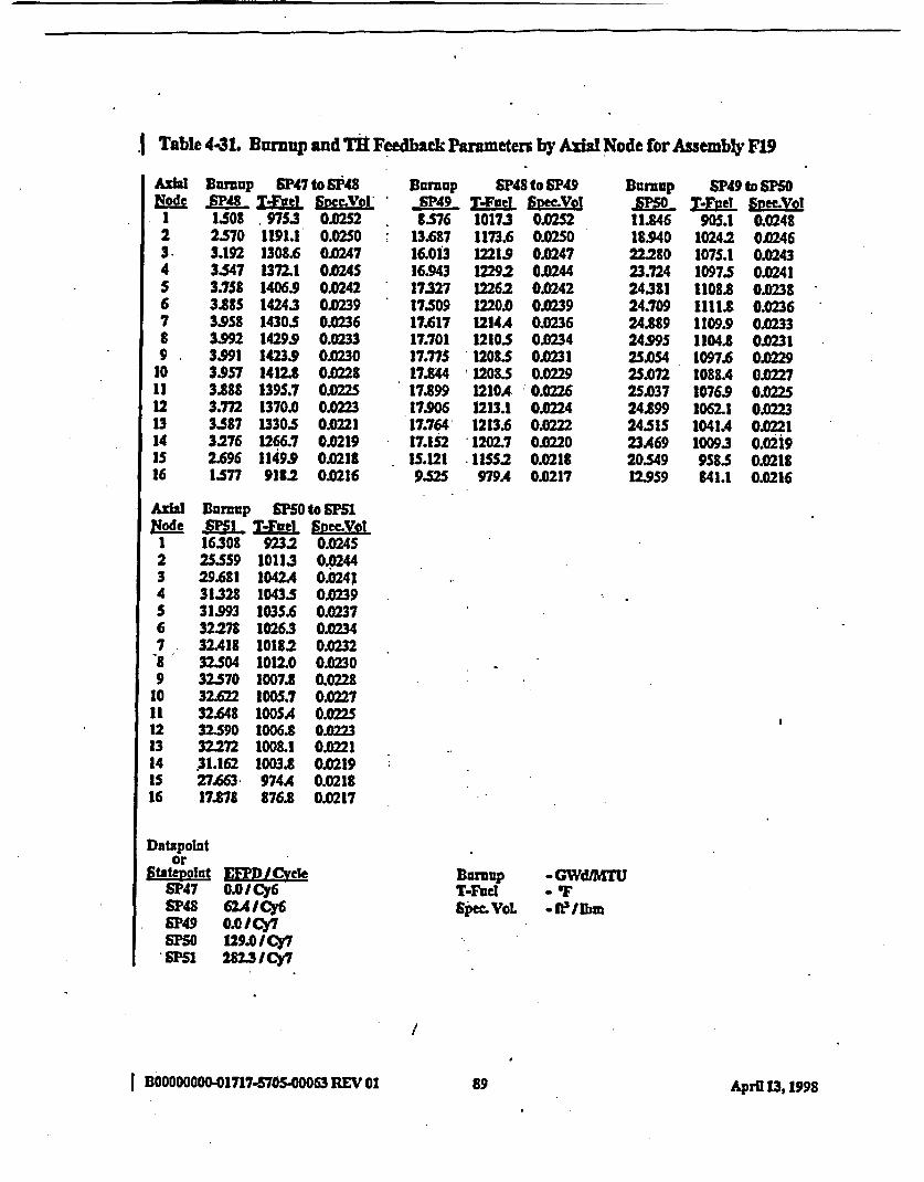
.1 Table 4-31. Burnup and Tft Feedbick Parameters by AxhI Node for Assemby F19
Node.123-4S6789.
10111213141516
Burmup SP47 to SP48RgPU T Fwed S peVal1.508 9753 0.02S22.570 1191.1' 0.02503.192 1308.6 0.02473-547 1372.1 0.024S3.758 1406S 0.02423.88S 14243 0.02393.958 1430.5 0.02363J992 1429.9 0.02333.991 1423.9 0.02303.957 1412. 0.J2283.888 1395.7 0.022S3.M 1370. 0.233J87 1330.5 0.2213276 1266.7 0.02192.696 1149.9 0.0218I1S77 918.2 0.0216
Burnup SP48 to SF49SlP49- Taftel S~Co8.S76 10173 0.0252
13.687 1173.6 0.02SO16.013 1221.9 0.024716.943 1229.2 0.024417327 1226.2 0.024217.509 1220.0 0.023917.617 1214A 0.023617.701 1210.5 0.023417.77S 1208.5 O23117.844 1208.5 0M2917.899 1210A 0.022617.906 1213.1 0.022417.764 1213.6 0.022217.1t2 1202.7 0.02201S.121 IISS2 0.02189S5 979A 0.0217
Burnup SP49 to SFS0
11.846 905.1 0.024818.940 1024.2 0.024622.280 1075.1 0.024323.724 1097.5 0024124381 1108.8 0.023824.709 1111.8 0.023624.889 1109.9 0.023324.995 1104.8 0.023125.054 1097.6 0.022925.072 1088A 0.02272S.037 1076.9 0.022S24.899 10621 0.022324.SIS 1041A .02123A69 10093 0021920.549 958.5 0.021812.959 841.1 0M16
Node1234S67.89
10111213141S16
Durmp SF5O to SF51.P!i Ltel Svec.VoI16308 9232 0.02452S.559 10113 0.024429.681 1042A 0.024131328 1043.S 0.023931.993 103S.6 0.023732.278 10263 0.023432.418 10182 0023232.504 1012.0 0.023032.S70 1007.8 0.022832.622 1005.7 0.022732.648 1005A 0.022532.590 1006.8 022332.272 1008.1 0.022131.162 1003.8 0.021927.663 974A 0.021817.878 876.8 O217
Datapolator
Statepolnt E.D/CvLelSP47 0.0 I Cy6SP48 62.4ICy6SP49 0.0 ICy7SF50 129.0 ICy7
'SF 2823ICy7
Bumnp -GWdIMTUT-Fuel .OSpec- VoL *fe3Iem
I BOOOOOOOO.01717.570500063 REV 8189 Aprfl 13, 1998

I Table 4-32. Bumup and TB Feedback Parameten by Axial Node for Assemby F21
Rode
1234S6789
1011121314lS16
Burnp SP47 to SP48JSP48- T-fel SveeeVol0.961 828.6 0.02361.666 981.6 0.023S2.06S 1061.0 0.02342.287 1102.5 0.02332A14 11242 0.02312489 1134.8 0.02292.9 11385 0.02282.S44 1137A 0.02262.539 1132A 0.02252.514 1123.7 0.02232A66 1110.9 0.02222.389 1092 0.0225 02.266 .1064.8 0.02192.059 1019.9 0.02181.679 9392 0.02170.63 7802 0.0216
sunup SP48 to SP49SFP49 T.Je1 SymVel5.377 856A 0.02368.6S57 974.1 0.0234
10.071 1009.8 0.023310.607 1014.7 0.023210.805 1OIOA 0.023010,881 1004A 0.022910914 999.2 0.022710.936 995.5 0.022610.956 993.3 0.022S10.974 992.7 0.02231OS87 993.5 0.0222tO972 9S.3 OJD22110.860 996.0 0.0219IA47 988.7 0.02189.161 951.7 0.02175.705 823.9 0.0216
sumup 5P49 to SM5JEEP Tfel. Smvol82S8 892.3 0.0245
13AIS 10195 0.0243IS831 1078.6 0.024116.891 1107A 0.023917373 1120. 0.023717.607 11242 0.023417.728 1123.6 0.023217.790 1120.1 0.023017.814 .1114.6 0.022817.806 1107.4 0.022617.7S4 1098.0 0.022417.617 1085.2 0A217.283 10663 0.022016A37 10342 0.021914234 973.6 0.0217
8.801 839.6 0.0216
123.-4S6789
1011321314ls .16
Rumup SF50 to SMIS I M-I et D Sec.Vot12.255 910.1 0.024319A90 100S.3 0.024222.697 1032.S 0.023923.982 1033.9 0.023724A93 1026.8 0.23S24.704 1018.6 0.023324.803 1011.7 0M3124.862 1006.7 0.022924.909 1003.7 0.022824.9S0 10026 0.022624.972 10033 0.022424.27 100S.9 0.022224.66S 10083 0.022123.744 10041 0JD21920.917 97SA 0.021813m 872.1 0.0216
Datapointor
Statepofut £ELLN/ICyceSP47 0.01 Cy6SP48 62A / Cy6SF49 O I/Cy7SF50 1.29.0I CY7SF51 282.3 1Cy7
T-FuecSpec. Vol.
-GWd1MTU-f T*fellbm
I BOOOOOOOO-01717-5705-00063 REV 01 April 13,1998

Table 4-33. Burnup and TR Feedback Parameters by Axial Node for Assembly l23
Node1234
6789
1011121314IS16
Burnup SF47 to SP48SP48 T-Ftel SmeLVol1.338 934.3 0.02SI2.364 1145.5 0.02493.079 1283.9 O.2473A90 1360.5 O443.716 1398.9 0.02413.846 14175 0.02383.918 14242 0.023S3.949 1423.3 0.02333.944 1416.8 0.02303.908 1405. 0M28.3 S35 1386.9 O.223.717 13602 OK0233.S31 13202 01X2213.221 1256A 0.02192.650 11412 0.0217LSS4 913.3 0.0216
Burnup SP48 to 5P49SP49 T4Fel Sme.Vol8.015 1008.0 O0253
13278 117H 5 OX25SIIS.912 1231.3 0.024816.969 1238.9 0.024517391 1236.5 0.024217.582 1230.5 0.023917.69D 122S.0 0.023617.770 12212 0M3417.840 12193 0M3117.903 1219A 0.022917.950 1221.2 0.022717348 1223.7 0.22417.791 12238 O.22217.1S8 1211.7 0AX220IS.111 1162.1 0.02189528 983S 050217
Burnup
9.678IS.94S19M420.34320.88021.12S21.253213292137821A04213982131621.03420.18217.6981l.lS4
SP49 to SlOT-Fuet Sec.Vet
741A 0C0229802.5 0.0229823.9 O.028832.1 0.02278345 0.0226833.8 O02831.0 0.224827.1 0.02238223 0.0222816.9 00221810.5 0M20802.8 0.0219792.8 0.0218778.5 0.217753.8 0.0217694.6 0.0216
AthW1
234S678910111213141516
Bhrnup S5 to s1,M T-el SpVof
12.037 762.0 OM.22919A64 810.9 0.022922344 817.9 0.022824310 81S56 CAM22724.829 809.8 0.02262S.036 803.8 OK2252S.129 798.7 O.0242S.183 794.7 O0.02225225 791.8 0.022252S9 7899 0.02212S.274 789.0 0202is223 7889 0.021924.964 788.9 0.021924.06S 786.1 0.021821.266 772.8 0.021713579 724.1 0.0216
Datapolator
statevotnt MD I CLMIeSP47 0.0 ICy6SP48 62A4ICy6SP49 0.0/Cy7
* SPSO 129.0 ICy7SPS1 282.3 ICy7
Burnup -GWd/MITUT-FueI - 'FSpec. VeL - fellbm
I BOODO000.171M7.50000 REV 01 91 Ap U. 131998

I Table 4-34. Burnup and TH Feedback Parameters by Axial Node for Assembly F25
AzWNode
I234567B9
1011121314IS16
Burnup SP47 to SP48;P_48 T-cel SVol
1.293 920A 0.02472250 1120.9 0.02462.27 1230.8 0J02433.16S 1292.1 0.02413.367 132S9 0.02393A89 1343.3 0.02363.S60 13SO.8 0.023435S95 13SI.S 0.02313599 1346.8 0.02293.574 1337.1 0.02263.S16 1321.8 0.02243AIS 1298.9 0.02223.247 12629 OA2202.9S8 1203A 0.02192.419 10945 0.02171.395 877.6 0.0216
BurUp SP48 to SP49;P-49 T--Fve SVMecOI73SS 959.1 0.0245
11.822 1103.0 0.024413.846 114S.0 0.024214.662 11492 0.023914.996 1143.6 O0.0371S.149 1136.3 0.023SIS239 11302 0.0233IS.308 1126.0 0.02311S.371 11239 0.0Q29ISA32 1123.7 00227ISA81 112S.3 0.022S15.A90 1128.3 o02231S.363 11302 002114.821 1123A O2191.SS 1082.5 0.02188211 926.6 0.0216
Barnup SP49 to SP50SPL. TVFode1 SncVYI9.178 767.5 0.0233
14.857 847.3 0.023217541 8842 0.023118.703 900.5 0.023019216 906.7 0.022B19.459 907.7 0.0227193S89 905.7 0.022619.667 901.9 .0.022419.717 897.0 0.022319.744 890.9 0.022219.737 883.7 0.022119.654 874A 0.022019373 .861.7 0.021918547 841S9 0.021816211 806.1 0.021710.IS3 726.9 0.0216
ARWNode
1234S678.9
1011121314is16
Durnup SF5O to SP51-M T--ea SpvO!v11.814 795.0 0.023318902 860.3 0.0232
22.120 871.7 0.023023A27 870.6 0.022923945 864.5 0.022824.156 8S79 0.022724.2S6 8S22 0.022624317 847.8 0.022424366 844.8 0.022324.411 43.0 0.022224.437 842.4 0.022124399 842.3 0.022024.149 843.0 0.021923261 8392 . 0.021320.514 823.2 0.021713.033 7S8.5 0.0216
Datapointor
Statenoint CMPD /CveSP47 0.0 Cy6SP48 62A./ Cy6SP49 0.0 I Cy7S50 1229.0lCy7SP51 2823 Cy7
BuRoUP -GWdMT-FaeI -"FSpMcA'L -fLI~bm
IDB00O000410717-5705.oo0063REV01 92g2 April 13,1998
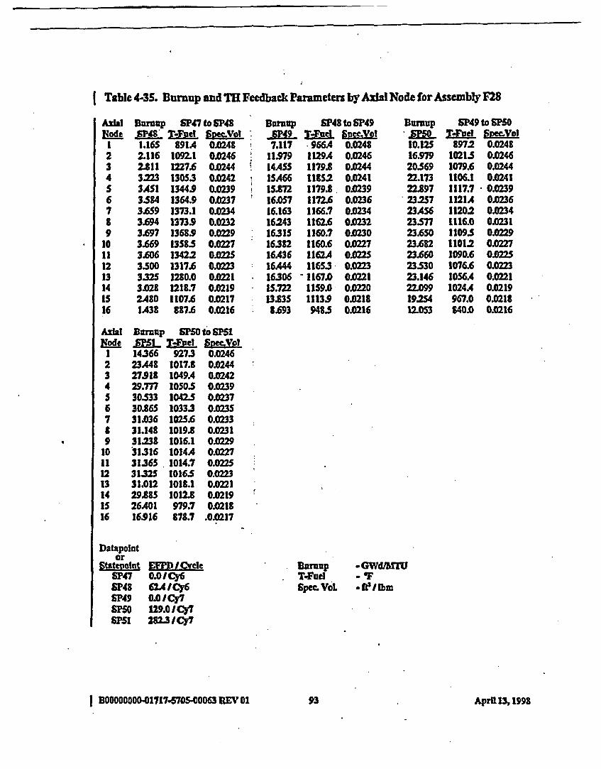
I Table 4-3S. Buniup and TH Feedback Parameters by Axial Node for Assembly F28
123456789
1011121314
16
Burnup SP47 to SF48Rff4" T-guel SRMo>Jol1.16S 891A 01.2482.116 IO2.1 Ol0462.811 1227.6 O2443.223 13053 0.02423A451 1344.9 O02393.584 1364.9 Ol2373.659 1373.1 0.0343.694 1373S 0.02323.697 1368S 0.02293.669 1358.S OK2273.606 13422 0.022S3.500 1317.6 C .02332S 1280.0 0.02213.023 1218.7 01)2192480 1107.6 .0J217IA38 887.6 0.0216
BSrnup SP48 to SP49S49 T-tFud SPEeLEGo7.117 966A 00248
11.979 1129A 0.24614ASS 1179. O.2441SA66 1IS2 0.02411S.72 1179.3 0.023916.057 1172.6 0023616.163 1166.7 0.023416243 1162.6 0.23216315 1160.7 0.023016382 1160.6 0.022716.436 11624 01022516A444 11653 0.022316306 - 1167.0 0.022115.722 IIS9.0 0.013.335 1113.9 0.02181.693 948S O.Q16
Burnup
10.1251697920.56922.17322.89723257234562357723.65023.68223.6602353023.14622.099192S4t2.053
SP49 to SF50T.Fue EpoSYo
8972 0.02481021.S 0.02461079.6 0.02441106.1 0.02411117.7 0.02391121A 0.023611202 0.02341116.0 0.02311109.S 0.022911012 0.02271090.6 O.2251076.6 OM.2231056.4 O.02211024A 0.0219967.0 0.0218840.0 0.0216
N~odeI234S6789
10112
1314is16
Burnup aF50 to Sf51T-ftel f2;eol
14366 9273 0.024623A48 1017.3 0.0244273913 1049. 0.024229.777 1050.5 0.023930.533 1042.5 0.2730.865 10333 0.023S31.036 1025.6 0.023331.148 1019.8 0M3131.238 1016.1 0.022931316 1014A 0022731360 1014.7 0.02253132S 10165 0.0231.12 1018.1 0022129.885 1012.3 0.021926A01 979.7 0M1816.916 378.7 .0.0217
Datapointor
Statevoatt EFPD/EtCI eSP47 O.OICy6SF48 62A ICy6SP49 0.0ICy7IPSO 129.0 ICy7SF51 282U3Cy7
Durnup -GWdV MT1JT-Fue - 'FSpec VoL *PfLI bm
I BOOW00000-017175705400063 REV 01 93 A~pr[113,1998

I Table 4-36. Bumup and T1 Feedback Parameters by Axial Node for Assembly G2
ARIANode
23456789
1011121314IS16
Bumup ISP49 to SF50-SM!; T dFPe SmeVol2.729 9262 002484.805 1134.1 0.02466.082 1242A 0.02446.748 1292.S 0.02417.092 1314.7 0A2397272 1323.0 0.02367.361 1323.6 0.02337390 1319.5 0.02317373 1312.0 OXZ29'7.316 1301A 002277210 1287.1 0.02247.033 1267.1 0.02226.734 1236.8 002216.193 118S2 002195.124 10863 0.02173.012 8802 0.0216
Burnup SM5 to SFS5
6M34 9883 0.02S211.616 1148.7 0.02S014217 12003 OJD24715.359 12133 OIX244IS.843 12105 0.024116.056 1203.8 023816.1S6 1197.6 0.023616207 11933 0.023316236 1191A 0.023116249 1191.8 0.022816234 11943 0.022616.150 1197.8 .0224IS.879 1198I S 0.022215.108 118S.0 O.2013.014 11313 0.02187.973 960.S 0.217
Table 4-37. Brnnup and TR Feedback Parameters by Axial Node for Assembly G4
AXJIsNode
I234S6789
10*lt121314IS16
Burnup SF49 to SF501SO T-Fuel Smeof3230 981A 002SI5448 1189.9 0.02506.686 t294A 0.02477337 1343.8 0.02447.692 13662 0.02417.887 13745 0.02387.989 1374.9 0.02358.030 1370.9 0.0233
8.023 1363.8 O0307.974 1353.8 0.022B7.874 1340.6 O.02257.701 13213 0.02237A03 1291.6 0.02216.848 1240.1 0.02195.711 11372 0.02183383 917.7 0.0216
Buruop ' PSO oSF51
-7.891 1015 0.02S312.827 1164.B 0.02SI15.246 12175 0.024816302 1228.9 0.024516.766 1224.7 0.024216.97.7 1216.9 0.023917.081 1209.8 0.023717.139 1204.9 O023417.176 .1202.S 0A3117.199 1202.8 0.022917.198 1205S 0.J22717.134 1210.0 0.022416895 1212.9 O.022216.159 1202.4 0.022014.041 1147.7 0.0218
.686 979A 0.0217
Datapointor
Statevoint E I .vLelSF49 0.0 iCy7SFO 129.0 I Cy7SF51 2823k Cy7
BurnupT4FueISpEc. VoL
* GWdAMT
-fei~bm
I B0000000001717-570540063 EV 01A 194 April 13,1998
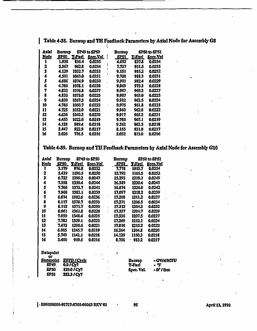
Table 4-38. Bumup and TB Feedback Paameters by Axal Node for Assembly G8
AXWNode
1234S6789
1011121314.1S16
BDunp S49 to 050
1.938 816A 0.023S3367 9623 0.02344.129 1032.7 0.02334.501 1063.0 0.02314.686 1074.9 0.02304.780 107.1 0102284.122 1076. 0.2274.U33 1073.0 0.022S41520 M0675 0.02244.785 1060.7 02234.72S 1OS2.0 0.02214.626 1040.2 0.02204ASS 1022.0 0.02194.128 989A 0.02183A47 922.9 0.02172.026 776.5 0.0216
Buraup SF50 to S 1
4.652 337.1 O.2347.737 9515 0.02339.151 9852 0.02329.700 988.3 0.02319.901 982.4 0.022993069 9753 O.02219.997 9693 O0.2279.987 96S.0 O122S9.982 92.5 0.02249.975 961.1 0.2239.960 92 0.2229.917 9652 0.02219.780 967.1 0.02199.362 962S 0.02188.1SS 931.0 0.02175.032 813.0 0.0216
I
Table 4-39. Bumup and TE Feedback Parameten by AxsIl Node for Assembly GIO
AIWNode
123456789
10111213141s16
Bump SP49 to SPSO
3.179 976. 0.02SA39 1190.5 0.02SO6.722 1299.2 0.02477.398 1350A OM447.766 1373.7 0.02417.68 1382.1 0M398.074 1382.6 0.02368.117 1377 0.02331.t12 1371.7 0.0230.061 1361.8 0.0228
7.9S9 1348A 002.7.782 1329.1 0237475 1298.6 .0216905 t245.7 0.0295.749 1141.1 0.02113A.40 919.5 0.0216
Buniup SF50 to SPS1- MX T-FLet SymVp7.778 1013.7 0.0254
12.792 1165.5 0.02S215.293 1219.1 0.024916389 1230A 0.024516.874 1226.0 0.024217.097 1218.2 O0.23917.203 1211.2 0.023717.271 1206.S 0.023417312 12043 0.023217337 1204.7 0.022917336 1207.5 O0.22717.269 1212.1 0.022417.018 121S2 0.022216.264 1204.8 O.02014.129 11503 0.02188.756 9832 0.0217
III
ii
Datapolntor
Statevolnft ED I CVcleSP49. OOICY7SPSO 129.0 ICy7
PS1 282.3 Cy7
I BOD00000z0017174570S.00063 REV 01
SpecMVOL
-GWd4FU- T-WtI~bm
95 April 1 1998
i
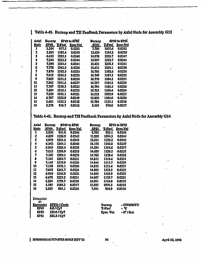
Table 440. Bumup and TR Feedback Parameters by Axial Node for Assembly G12
A112l&ode
234S6789
1011121314IS16
Bunuzp SP49 to 90-SM Vftl Svm1g3204 *977.5 0021S.39S 1183A 0.02496.610 1285.5 0.02467.246 1333.2 0.02447.S90 13S4A 0.02417.77S 1362.2 0.02387.876 1362.S 0.02357.91S US15 0.02327909 13S13 0.02307.862 13415 0.02277.767 13283 0.022S7.604 1310.1 0.02237320 1282.1 0.02216.787 1232.9 0.02195.681 11333 0.2183378 916.7 0.0216
BDUP SF50 to mi5JPSI Mod Spec-Vol7.784 1007. 022
12.629 1154.2 0.02SO1497=8 1203.7 0.024715.987 1213.7 0.024416A21 1208.5 0.024116.611 1200.1 0.023B16.701 1192.6 O.23616.749 11873 0.023316.779 1184.5 0.023116.797 1143 02916.794 11865 0.022616.735 1190A 0.022416513 1192.9 0.022215220 1184.0 0G22013.784 1133.1 0S1885SS 970.0 0.0217
Table 441. Burnup and TH Feedback Parameters by Axial Node for Assembly G14
Axial Boroup SP49 to S0Node -S50 TWod SvmVgI
1 2.830 931.0 0.02462 4.8S9 1126.9 0.024S3 S.97S 12215S 0.2434 6542 1264.1 0.0240S 6.84S 1282A 0.02386 7.012 1288.9 0.023S7 7.102 1289.1 0.02338 7.143 1285.7 0.02319 7.148 1279.9 00228
10 7.118 1272.1 O2611 7.048 1261.7 0.022412 6.918 1246.9 0.013 6.678 12232 0.022114 6.204 1179.7 0.0219IS S.189 1088.2 0.021716 3.063 884.1 0.0216
Datapointor
Statevolnt KM I CyvceSP49 0.0ICy7SF50 129.0ICy7S51 2823 ICy7
RUnup SFO to SF51JS1L TIe lyeeVol6.79S 953.1 0.0246
11209 10943 0.024413311 1135.5 0.024214.175 1140.8 0.02391454 1134.6 0.023714.689 1126.5 0.0235
14.76S 1119A 0.023314.811 1114A 0.023114.846 1111.7 OQ22914.875 1111A 0022714.890 11133 .02514.860 1116.9 0.022314.687 1119.7 0.022114.091 1114.0 0.021912.282 10743 0.02187.591 924.9 0.0216
Burnup . GWdAMTUT-Fue a 'FSpec.VoL -WIP bm
I BDOOOOOOO01717-5705.00063 REV 01 96 April 13, 1998
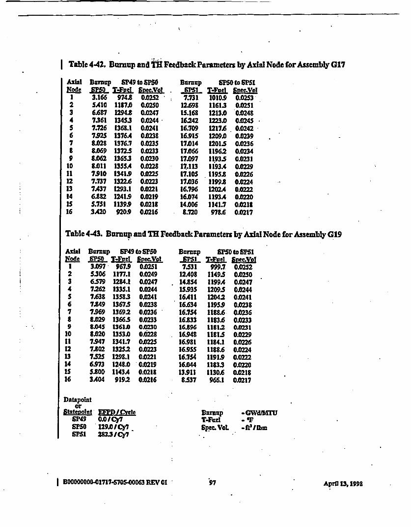
Table 4.42. Buup and TFeedbackParameters by al Node forAssembly G17
AxhiNode
1234S6789
1011121314Is16
Burnup SP49 to SPMOJSEM TiFoef 90Mlot
3.166 974.8 0.0232S.410 1187.0 0.02506.687 1294.8 0.02477361 13453 0.02447.726 1368.1 0.02417.S2 1376A 002388.028 1376.7 0.023S8.069 1372.5 0.02338.062 13653 0.02308.011 1355. 0M287.910 1341.9 O.227.737 1322.6 0.0237U37 1293.1 0.2216.882 1241.9 0.02195.751 1139.9 0.021t3.420 920.9 0M216
BDraup sm5to 6PSIFlSl T/Fed 92Mxxot7.731 1010.9 O.OS3,
12.698 11613 0.02SIIS.168 1213.0 0.024816.242 1223.0 0.024S16.709 1217.6 0.024216.915 1209.0 0.023917014 1201.5 0.023617066 1196.2 0023417.097 1193.5 0.023117.113 3i93A 0.022917.105 119S.8 0122617JD36 1199.8 0.022416.796 1202A4 0.022216.074 1193.4 0022014.006 1141.7 0.02188.720 978.6 0.0217
Table 4.43. Burnup and TH Feedback Parameters by Axial Node for Assembly G19
1Node
234S6789
101121314Is16
Bnrzaup S49 to SF50R.P50 TIEv.el Svec.Vol3.097 967.9 0.02515306 1177.1 0.02496579 1284.1 0.02477.262 133S.1 0.02447.638 1358.3 0.02417.49 1367.5 0.02387.969 1369.2 0.02368.029 1366S 0.02338.045 1361. 0.02308.020 1353. 0.02287M47 1341.7 0027802 132S.2 0.02237.525 1298.1 0.02216.973 1248.0 0.02195.800 1143A 0.02183.404 919.2 0.0216
Buranup S5S0 to SFS1,P51 T-Tuel SmwYVof7.531 999.7 0.0252
12A08 1149.5 0.025014JS4 1199A 0.0247IS93S 1209.5 0.024416A11 12042 0.024116.634 1195S.9 0.023816.754 1188.6 0.023616.833 1183.6 0.023316.896 1181.2 0J23116.948 11815 0.022916.981 1184.1 0.022616.95S 11886 0.022416.7S4 1191.9 0.02216.044 11833 0.022013.911 1130.6 02188S7 966.1 0.0217
Burnup aGWd~MTUTFW . 'IFSpec. VoL -fe/Ibm
Datapointor
Statevolnt £EM. ICyrceSP49 0.0I/Cy7iPSO ' 129.01Cy7SPSI 282.3 ICy7
I BOOOOOOOO-01717-570S.00063 REV 01 797 April 13,1X998
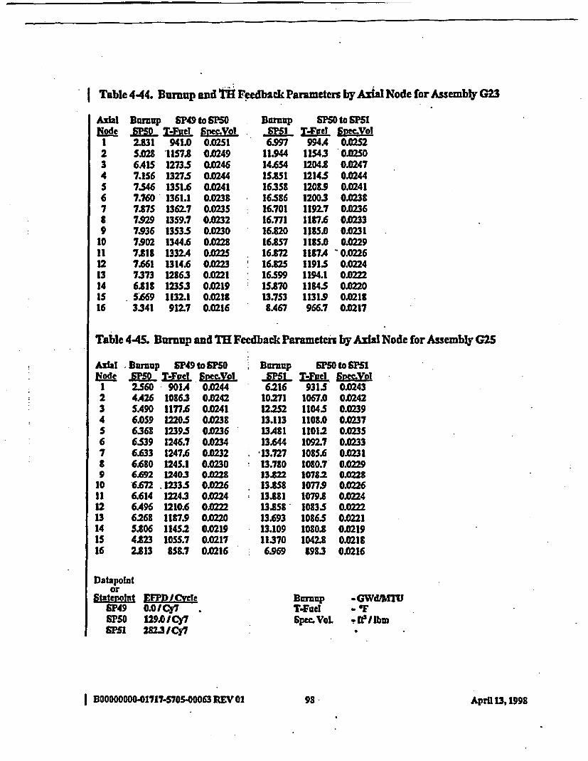
| Table 4-44. Burnup Eand tl Feedback Parameters by Axial Node for Assembly G23
Axial
123456789
1011121314lS16
BDup SP49 to SM5SJMI° T-EHfte SMYo 02.831 941.0 0.02515.08 1157. 0.02496A15 127335 0.02467.156 13275 0.02447.S46 1351.6 0.02417.760 1361.1 0.02387.87S 1362.7 0.02357.929 13S9.7 0.02327.936 13S335 OJ2307.902 1344.6 0.02287.11 1332.4 OX2257.661 1314. 0.02237373 1286.3 0.02216.18 123S.3 0.0219S569 1132.1 0.02183.341 912.7 0.0216
Burnup SF5D0to SP51, PSI MvFel SpeetVol6.997 994A 0.0252
11.944 11543 0.02S014.654 1204.8 0.0247IS3851 12145 0.024416358 1208.9 0.024116586 12003 0.023816.701 11927 0.023616.771 1187.6 0.023316.820 1185.0 0.023116.857 1185.0 0.0229167M 1187A ' 0.022616.82S 11915 0.022416S99 1194.1 002215t70 111435 O02013.7S3 11319 0.02188A67 966.7 0.0217
Table 445. Burnup and TR Feedback Parameters by Axial Node for Assembly G25
Axial Burnup SP49 to S ONode SR5 TLFueL STYVol1 2360 901A 0.02442 4A26 10863 .02423 SA90 1177.6 0.02414 6.059 12205 0.2385 6.368 1239.5 0.02366 6539 1246.7 0.02347 6.633 1247.6 0.0232t 6.680 124S.1 0.0309 6.692 1240.3 0228
10 6.672 .1233.5 0022611 6.614 12243 0.022412 6A96 1210.6 0022213 6268 1187.9 OM2014 S.806 1145.2 0.0219IS 4.23 IOSS.7 0.021716 2.813 858.7 0.0216
Datapointor
Statevolnt EE'JDCyvleSP49 0.1 CY7SP50 129.0/Cy7SF M /2823ICy7
Bumrnp PSO toPS IMSI T-Faeu £SyVol
6216 9315 0.024310271 1067.0 0.024212252 11045 0.023913.113 1108.0 0.023713A81 11012 0.023513.644 1092.7 0.023313.727 1085.6 0.023113.780 1080.7 0.022913.822 10782 0.022813.858 10779 0022613.881 1079.8 0.022413.858 10835 0.022213.693 10865 0.022113.109 1080.8 0.021911370 1042.8 0.02186.969 1983 0.0216
BDurnpT-FueISpec.VoL
-GWdAMT
*IWl3ibm9
I B0000D000-01717-570S-00063 REV 01 98 April 13,1999
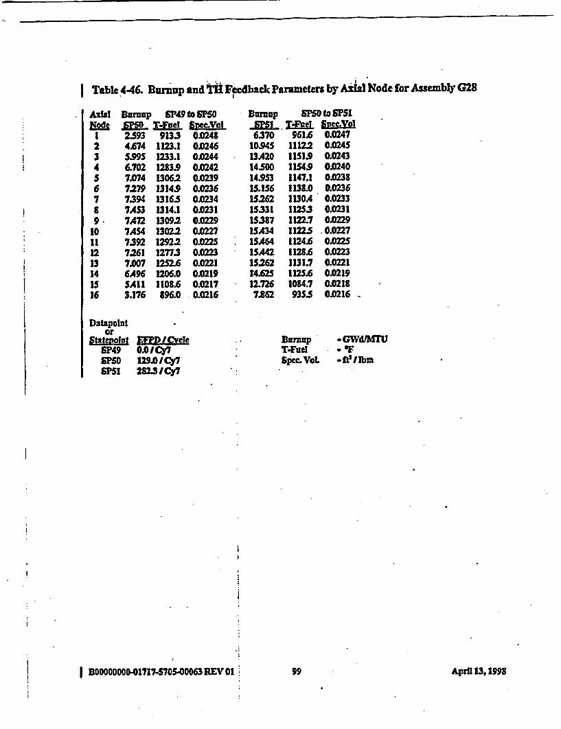
I Table 446. Burnup and Ti1 Feedback Parameters by Ai Node for Assembly G28
Axial Dfrzzup SP49 to E0EcdNe P T-Fuet SneVol
1 2.593 9133 0.02482 4.674 1123.1 0.02463 5.995 1233.1 0.02444 6.702 1283.9 0.0242S 7.074 1306.2 0.02396 7.279 1314.9 0.02367 7.394 1316.5 0.02348 7AS3 1314.1 0.02319. 7A72 1309.2 00229
10 7AS4 13022 0.022711 7.392 1292.2 0Z022512 7261 1277.3 0.2313 7.007 12S2.6 0.022114 6A96 1206.0 0.0219IS SAI 1108.6 0.021716 3.176 196.0 0.0216
Datapolntor
Statepolnt KEM/ CycleSP49 O.OICy7SPSO 9.ICY7SFS5 2823Cy7
| B00000oo 001717-570S-00063REVO:
Burnup 5m0 to SF51- TPM T-Fae ,SpVol6370 961.6 0.0247
10.945 11122 OM.24513A20 1151.9 0.024314.500 1154.9 0.024014.953 1147.1 0.02381t.156 1138.0 0.023615262 1130A 0.0233IS331 11253 0.0231IS387 1122.7 0.0229ISA34 1122.5 .0.0227ISA64 1124.6 0.022S1SA42 1128.6 0.02231S262 1131.7 0.0221r4.62s 112S.6 0.021912.726 1084.7 0.021K
7.862 935.5 0.0216
.. Barnup aGWd4TU
T.Fiu - FSpec.VOL -fI~bm
i
;
99 9April 13, 198
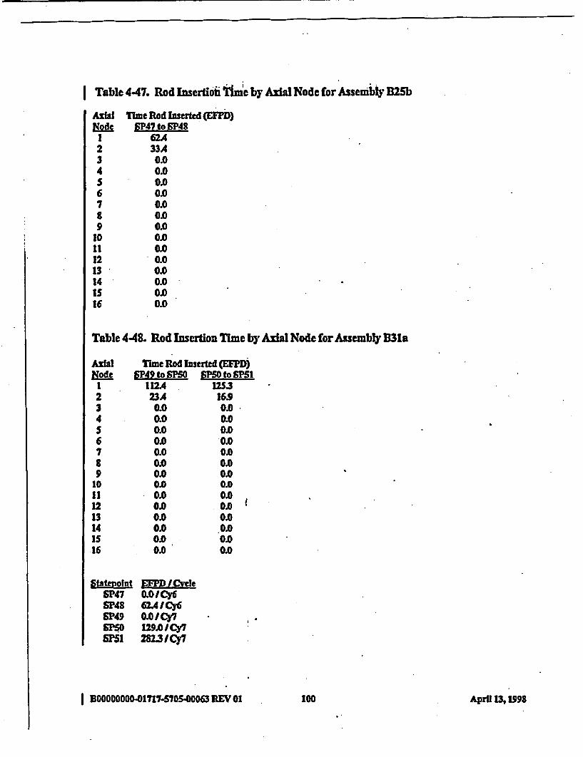
Table 447. Rod Insertiohi iTne by Axial Node for Assembly D25b
Axial TIme Rod Inserted (EOD)Node SP47 to SP48
1 ~62A2 33A3 0.04 0.0S 0.06 0.07 0.08 0.09 0.0
10 0.0it 0.012 0.013 0.014 0.0IS 0.016 0o
Table 448. Rod Insertion Time by Axial Node forAssembly B3la
Axial Time Rod Inserted (PD)de P492t M toSP51
I 112A. 12S32 23.4 16.93 0.0 0.04 0.0 0.0S 0.0 0.6 0.0 0.07 0.0 0.08 0.0 0.09 0.0 0.0
10 0.0 0.011 0.0 0.012 0.0 0.013 0.0 0.014 0.0 0.015 0.0 0.0.16 0.0 0.0
Ststevoint EPY /CycleSP47 O.O0Cy6SP48 624 ICy6SN49 0.0ICY7SP0 129.0 /Cy7SF51 282.3 /CY7
I BOOOOOOO01717.5705063 REV 01 100 Apra 13% 1998
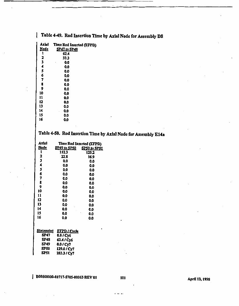
Table 4-49. Rod Insertion Time by Axial Node for Assembly D8
Axial Time Rod Inserted (EFPD)Node SP47 to SP48
1 62A2 33.33 0.04 0.05 0.06 0.07 0.08 0.09 0.0
10 0.011 0.012 0.013 0.014 0.015 0.016 0.0
Table 4-50. Rod Insertion Time by Axial Node for Assembly E14a
Axial Time Rod Inserted (EFPD)&ode SP49 to SPSO S to SP1 112.3 125.22 22.8 16.93 0.0 0.04 0.0 0.05 0.0 0.06 0.0 0.07 0.0 0.08 0.0 0.09 0.0 0.0
10 0.0 0.011 0.0 0.012 0.0 0.013 0.0 0.014 0.0 0.0IS 0.0 0.016 0.0 0.0
Statepolnt EFPD / CvclSP47 0.0 / Cy6SP48 62.4/ Cy6SP49 0.0/Cy7SPSO 129.0/Cy7SPS1 282.3/Cy7
IBOOO0OOOO-01717-570S..00063REVO0I10101 April 13, 1998
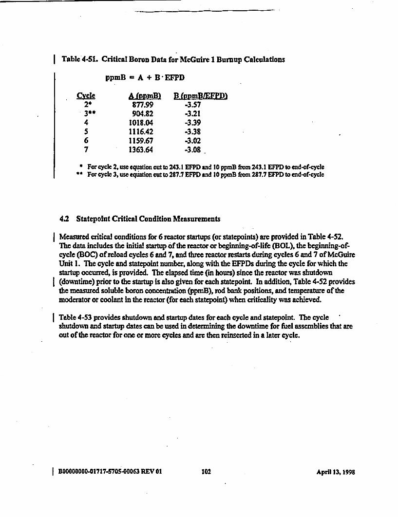
Table'4-51. Critical Boron Data for McGuire 1 Burnup Calculations
ppmB - A + B *EFPD
C~vcle A (IpmB) B (ppmBXEFPD)2* 877.99 -3.573** 904.82 -3.214 1018.04 -3.395 1116.42 -3.386 1159.67 -3.027 1363.64 -3.08
For cycle 2, use equation out to 243.1 EFPD and 10 ppnB from 243.1 EFPD to end-of-cycleFor cycle 3, use equation out to 287.7 EFPD and 10 ppmB from 287.7 EFPD to end-of-cycle
42 Statepolnt Critical Condition Measurements
Measured critical conditions for 6 reactor startups (or statepoints) are provided in Table 4-52.The data includes the initial startup of the reactor or beginning-of-life (BOL), the beginning-of-cycle (BOC) of reload cycles 6 and 7, and three reactor restarts during cycles 6 and 7 of McGuireUnit 1. The cycle and statepoint number, along with the EFPDs during the cycle for which thestartup occurred, is provided. The elapsed time (in hours) since the reactor was shutdown(downtime) prior to the startup is also given for each statepoint. In addition, Table 4-52 providesthe measured soluble boron concentration (ppmB), rod bank positions, and temperature of themoderator or coolant in the reactor (for each statepoint) when criticality was achieved.
Table 4-53 provides shutdown and startup dates for each cycle and statepoint. The cycleshutdown and startup dates can be used in determining the downtime for fuel assemblies that areout of the reactor for one or more cycles and are then reinserted in a later cycle.
I BOOCOODO-01717-5705-00063 REV 01 102 April 13, 1998

. q
I Table 4-52. Statepoint Data for McGuire Unit 1- Measured Critical Conditions
Cycle(SP~
I(SP46)
6(SP47)
6(SP48)
E0.PD
0.0
06.
62A4
Downtimetbouu
0
1872
1505
wDmB
1279
1538
1320
Rod Positions, cm above bottom of fuel' T(coolant)Bk CA k CB Bk CC Bk C]D
WD WD 313 129 558.9
WD WD 358 174
WD WD 315 131
558.1
557.9
7(SP49) 0.0 3120 1689 WD WD 313 129 558.8
7(SP50) 129.0 711 1335 WD WD 278 94 558.2
7(SP51) 282.3 451 931 WD WD WD 283 557
Bk -RodfBankWD - Rod Vithdawn
* Measured from the bottom of active fuel region to bottom of control rod absorber region (See Figure 2-17).
I
I
I Table 4-53. Statepoint Data for McGuire Unit 1 - Shutdown and Startup Dates
Cvdle(SM E D Shutdown -Date
1(SP46) 0.0 -
2(-)* 0.0 24 Feb 1984
3(-)* 0.0 19Apr 1985
4(-)* 0.0 16 May 1986
0.0 04 Sep 1987
6(SP47)4 0.0 12 Oct 1988
6(SP48) 62.4 07 Mar 1989
7(SP49)* 0.0 08 Jan 1990
7(SP50) 129.0 15 Oct 1990
7(SP51) 282.3 25 Apr 1991
408.0 (EOC3 20 Sep 1991
EOC = end-of-cycle
* Shutdown date is for previous cycle.
Startup Date
08 Aug 1981
28 Apr 1984
24 Jun 1985
07 Sep 1986
12 Nov 1987
29 Dec 1988
09 May 1989
18 May 1990
14 Nov 1990
14 May 1991
I BDOOOOOOO-01717-5705-00063 REV 01 103 April 13,1998
I 5.0 CONCLUSIONS
The data reported herein is acceptable for quality affecting activities and for use in analysesaffecting procurement, construction, or fabrication. The classification analysis for the repository(which includes the waste package) carries TBV-228 because of the preliminary status of thebasis for the MOR design. This report conservatively assumes that the resolution of TBV-228will find the waste package to be quality affecting; consequently, use of any of the data reportedherein does not need to carry TBV-228.
BOOOOOOO-01717-S70500063 REV 01 104 April 13,1I998
6.0 REFERENCES
1. QualityAssurance Programfor Framatome Cogema Fuels DocumentNumber. 56-1177617-04, FCF, August 5, 1996.
2. Classification of the Preliminary MGDS Repository Design, Document Identifier Number(DI#) BOOOODOOO-01717-0200-00134 REV 00, Civilian Radioactive Waste ManagementSystem (CRWMS) Management and Operating Contractor (M&O).
3. QAP-2-0 Activity Evaluations, ID No. WP-06, Develop Technical Documents, CRWMSM&O, August 3,1997.
| 4. Quality Assurance Requirements and Description, DOE/RW-0333P, REV 7, DOE OCRWM.
5. McGuire I NEMO Depletion and Statepoints (HL;V), Document Number: 32-1267165-00,FCF.
I BOOOW000O01717-5705-00063 REV 01 105 AprU 13,1998