
Axial Piston Variable Pump RE 92735/10.07 1 A10VNO · Linear Motion and Hydraulics Assembly...
16
Linear Motion and Assembly Technologies Service Pneumatics Hydraulics Electric Drives and Controls Series 52 Series 53 Axial Piston Variable Pump A10VNO Technical Data Sheet Series 52/53 Size 28...85 Nominal pressure 210 bar Peak pressure 250 bar Open circuit RE 92735/10.07 1/16 Replaces: 11.05 Features – Axial piston variable pump in swashplate design for hydrostatic drives in open circuits – Flow is proportional to drive speed and displacement. It can be infinitely varied by adjustment of the swashplate. – High power to weight ratio-small dimensions – Low noise level – Permissible continuous pressure 210 bar – Axial and radial loading of drive shaft possible – Pressure and flow control – Short response times – Well proven A10-technology – Extreme small mounting dimensions – Cost effective alternative to fixed displacement pumps – Costs -optimized design Contents Ordering code - Standard program 2 Available versions 2 Fluids 3 Technical data 4 DRS - Pressure and flow control 6 DRS - Pressure and flow control 7 Unit dimensions, size 28 8 Unit dimensions, size 45 9 Unit dimensions, size 63 10 Unit dimensions, size 85 11 Installation notes 12 General notes 16
Transcript of Axial Piston Variable Pump RE 92735/10.07 1 A10VNO · Linear Motion and Hydraulics Assembly...
Linear Motion andAssembly Technologies ServicePneumaticsHydraulics
Electric Drives and Controls
Series 52 Series 53
Axial Piston Variable Pump A10VNO
Technical Data Sheet
Series 52/53 Size 28...85Nominal pressure 210 barPeak pressure 250 barOpen circuit
RE 92735/10.07 1/16Replaces: 11.05
Features– Axial piston variable pump in swashplate design for
hydrostatic drives in open circuits
– Flow is proportional to drive speed and displacement. It can be infinitely varied by adjustment of the swashplate.
– High power to weight ratio-small dimensions
– Low noise level
– Permissible continuous pressure 210 bar
– Axial and radial loading of drive shaft possible
– Pressure and flow control
– Short response times
– Well proven A10-technology
– Extreme small mounting dimensions
– Cost effective alternative to fixed displacement pumps
– Costs -optimized design
ContentsOrdering code - Standard program 2
Available versions 2
Fluids 3
Technical data 4
DRS - Pressure and flow control 6
DRS - Pressure and flow control 7
Unit dimensions, size 28 8
Unit dimensions, size 45 9
Unit dimensions, size 63 10
Unit dimensions, size 85 11
Installation notes 12
General notes 16
2/16 Bosch Rexroth AG A10VNO | RE 92735/10.07
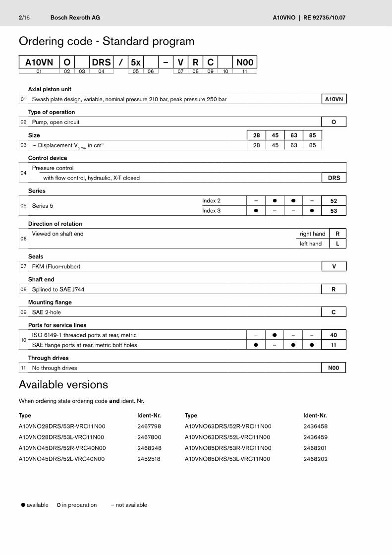
Axial piston unit
01 Swash plate design, variable, nominal pressure 210 bar, peak pressure 250 bar A10VN
Type of operation
02 Pump, open circuit O
Size 28 45 63 85
03 ~ Displacement Vg max in cm3 28 45 63 85
Control device
04Pressure control
with flow control, hydraulic, X-T closed DRS
Series
05 Series 5Index 2 — — 52
Index 3 — — 53
Direction of rotation
06Viewed on shaft end right hand R
left hand L
Seals
07 FKM (Fluor-rubber) V
Shaft end
08 Splined to SAE J744 R
Mounting flange
09 SAE 2-hole C
Ports for service lines
10ISO 6149-1 threaded ports at rear, metric – – – 40
SAE flange ports at rear, metric bolt holes – 11
Through drives
11 No through drives N00
Available versionsWhen ordering state ordering code and ident. Nr.
Type Ident-Nr. Type Ident-Nr.
A10VNO28DRS/53R-VRC11N00 2467798 A10VNO63DRS/52R-VRC11N00 2436458
A10VNO28DRS/53L-VRC11N00 2467800 A10VNO63DRS/52L-VRC11N00 2436459
A10VNO45DRS/52R-VRC40N00 2468248 A10VNO85DRS/53R-VRC11N00 2468201
A10VNO45DRS/52L-VRC40N00 2452518 A10VNO85DRS/53L-VRC11N00 2468202
available in preparation – not available
A10VN O DRS / 5x – V R C N0001 02 03 04 05 06 07 08 09 10 11
Ordering code - Standard program

RE 92735/10.07 | A10VNO Bosch Rexroth AG 3/16
Prior to project design, please see our technical data sheets RE 90220 (mineral oil), RE 90221 (environmentally acceptable fluids) and RE 90223 (HF-fluids) for detailed information on fluids and operating conditions.
When using HF- or environmentally acceptable fluids attention must be paid to possible limitations of the technical data, if necessary contactus. (when ordering, please state in clear text the fluid to be used) Operation on Skydrol fluid is only possible after consultation with us
Operating viscosity rangeFor optimum efficiency and service life we recommend that the operating viscosity (at operating temperature) be selected in the range
nopt = opt. Betriebsviskosität 16 ... 36 mm2/s
referred to tank temperature (open circuit).
Limit of viscosity rangeFor critical operating conditions the following values apply:
nmin = 10 mm2/s for short periods (t ≤1 min) at max. permissible leakage oil temperature of 115 °C.
Please note, that the max fluid temperature of 115 °C is also not exceeded in certain areas (for instance bearing area) The fluid temperature in the bearing area is approx. 5° C higher than the average leakage fluid temperature.
nmax = 1600 mm2/s for short periods (t ≤ 1 min) on cold start (tmin = p ≤ 30 bar, n ≤ 1000 rpm, -25 °C)
At temperatures between -25 °C and -40 °C special measures may be required, depending on installation conditions. Please consult us for further information.
For detailed information on operation with low temperatures see data sheet RE 90300-03-B.
Selection diagram
FluidsNotes on the selection of the hydraulic fluidsIn order to select the correct fluid, it is necessary to know the operating temperature in the tank (open circuit ) in relation to the ambient temperature.
The fluid should be selected so that within the operating temperature range, the viscosity lies within the optimum range (nopt), see shaded section of the selection diagram. We recom-mend to select the higher viscosity grade in each case.
Example: at an ambient temperatue of X °C the operating tem-perature in the tank is 60 °C . In the optimum viscosity range (nopt; shaded area) this corresponds to viscosity grades VG 46 resp. VG 68; VG 68 should be selected
Important: The leakage oil (case drain oil) temperature is influ-enced by pressure and input speed, and is always higher than the tank temperature. However, at no point in the circuit may the temperature exceed 115 °C.
If it is not possible to comply with these conditions because of extreme operating parameters or high ambient temperatures, please consult us.
Filtration of hydraulic fluidThe finer the filtration the better the achieved cleanliness of the hydraulic fluid and the longer the life of the axial piston unit.
To ensure a reliable functioning of the axial piston unit, a mini-mum cleanliness of
20/18/15 to ISO 4406 is necessary.
At very high operating temperatures (90 °C to max. 115 °C) a cleanliness of at least
19/17/14 toISO 4406 is necessary.
If above mentioned grades cannot be maintained please con-sult us.
tmin = -40°C tmax = +115°C
5
10
4060
20
100
200
400600
100016002500 0° 20° 40° 60° 80° 100°-40° -20°
νopt.
16
36
5
1600
-40° -25° -10° 10° 30° 50° 90° 115°70°0°
VG 22
VG 32
VG 46
VG 68
VG 100
Fluid temperature range
Visc
osity
n [
mm
2 /s]
�/16 Bosch Rexroth AG A10VNO | RE 92735/10.07
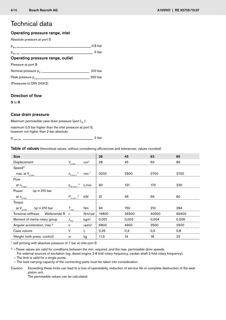
Table of values (theoreticalvalues,withoutconsideringefficienciesandtolerances;valuesrounded)
Size 28 �5 63 85
Displacement Vg max cm3 28 45 63 85
Speed2)
max.atVgmax n0 max 11) min-1 3200 2900 2700 2700
Flow
atn0max qV0 max 11) L/min 90 131 170 230
Power Dp=210bar
atn0max P0 max 11) kW 31 46 59 80
Torque
atVgmaxDp=210bar Tmax Nm 94 150 210 284
Torsionalstiffness WellenendeR c Nm/rad 14800 26500 40500 69400
Momentofinertiarotarygroup JTW kgm2 0,001 0,002 0,004 0,006
Angularacceleration,max.2) a rad/s2 6800 4900 3500 2500
Casevolume V L 0,25 0,3 0,5 0,8
Weight(withpress.control) m kg 11,5 14 18 22
1)selfprimingwithabsolutepressureof1baratinletportS
2)–Thesevaluesarevalidforconditionsbetweenthemin.required.andthemax.permissibledrivespeeds. Forexternalsourcesofexcitation(eg.dieselengine2-8foldrotaryfrequency,cardanshaft2-foldrotaryfrequency). –Thelimitisvalidforasinglepump. –Theloadcarryingcapacityoftheconnectingpartsmustbetakenintoconsideration.
Caution: Exceedingtheselimitscanleadtoalossofoperatabiliy,reductionofservicelifeorcompletedestructionoftheaxial pistonunit. Thepermissiblevaluescanbecalculated
TechnicaldataOperating pressure range, inletAbsolutepressureatportS
pabsmin__________________________________________0,8bar
pabsmax __________________________________________ 5bar
Operating pressure range, outletPressureatportB
NominalpressurepN____________________________ 210bar
Peakpressurepmax______________________________ 250bar
(PressurestoDIN24312)
Direction of flowStoB
Case drain pressureMaximumpermissiblecasedrainpressure(portLX):
maximum0,5barhigherthantheinletpressureatportS,howevernothigherthan2barabsolute.
pLabsmax _________________________________________ 2bar
RE 92735/10.07 | A10VNO Bosch Rexroth AG 5/16
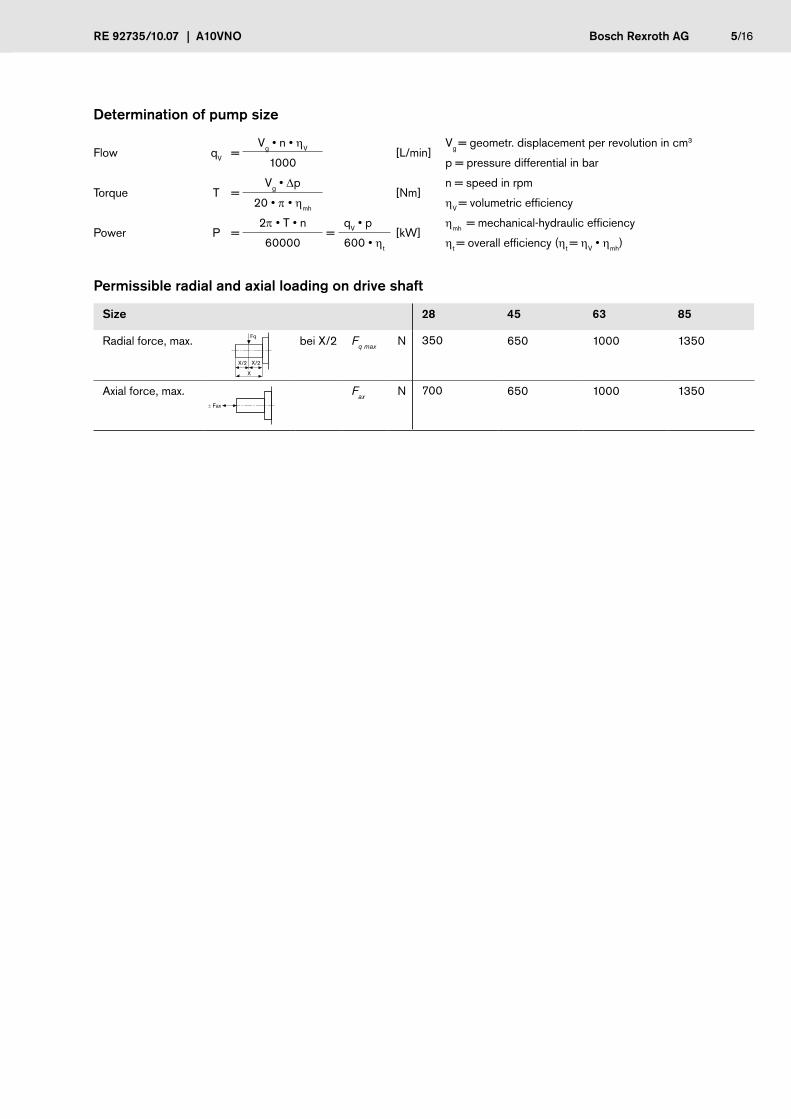
Determination of pump size
Flow qV =Vg • n • hV [L/min]
Vg = geometr. displacement per revolution in cm3
1000 p = pressure differential in bar
Torque T =Vg • Dp
[Nm]n = speed in rpm
20 • p • hmh hV = volumetric efficiency
Power P =2p • T • n
=qV • p [kW]
hmh = mechanical-hydraulic efficiency
60000 600 • ht ht = overall efficiency (ht = hV • hmh)
Permissible radial and axial loading on drive shaft
Size 28 45 63 85
Radial force, max. bei X/2 Fq max N 350 650 1000 1350
Axial force, max. Fax N 700 650 1000 1350
Fq
X
X/2 X/2
± Fax
6/16 Bosch Rexroth AG A10VNO | RE 92735/10.07
300
250210
150
100
50
0
200
20
210
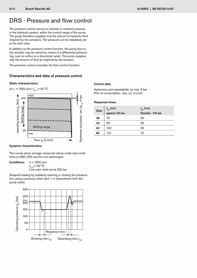
The pressure control serves to maintain a constant pressure in the hydraulic system, within the control range of the pump. The pump therefore supplies only the amount of hydraulic fluid required by the actuators. The pressure can be steplessly set at the pilot valve.
In addition to the pressure control function, the pump flow to the actuator may be varied by means of a differential pressure (eg. over an orifice or a directional valve). The pump supplies only the amount of fluid as required by the actuator..
The pressure control overrides the flow control function.
Characteristics and data of pressure control
Static characteristics
at n1 = 1500 rpm; tfluid = 50 °C
Control data
Hysteresis and repeatability Dp max. 3 bar Pilot oil consumption max. ca. 3 L/min
Response times
Dynamic characteristics
The curves show average measured values under test condi-tions to SAE J745 and the unit submerged.
Conditions: n = 1500 rpm
tfluid = 50 °C Line main relief set at 250 bar
Stepped loading by suddenly opening or closing the pressure line using a pressure relief valve 1 m downstream from the pump outlet.
Stroking time tSA Destroking time tSE
Response time tOpe
ratin
g pr
essu
re p
B [
bar]
Setting range
oper
atin
g pr
essu
re p
B [
bar]
Hys
tere
sis
and
pres
s. ri
se D
p max 4
bar
Flow qV [L/min]
Set
ting
rang
e
min
max
SizetSA
[ms]
against 150 bar
tSE [ms]
Standby - 210 bar
28 75 30
45 90 45
63 100 55
85 110 70
DRS - Pressure and flow control
RE 92735/10.07 | A10VNO Bosch Rexroth AG 7/16
20
210
B
L L1
L21)
S
X
does not belong to supply
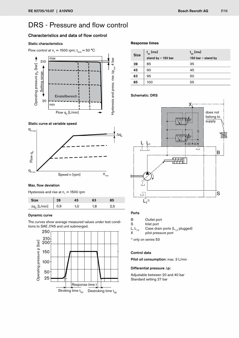
Ports
B Outlet port S Inlet port L, L1,2 Case drain ports (L1,2 plugged) X pilot pressure port
1) only on series 53
Control data
Pilot oil consumption: max. 3 L/min
Differential pressure Dp:
Adjustable between 20 and 40 bar Standard setting 27 bar
Static characteristics
Flow control at n1 = 1500 rpm; tfluid = 50 °C
qV min
qV max
nmax
∆qV
Static curve at variable speed
Flow
qV
Speed n [rpm]
Max. flow deviation
Hysteresis and rise at n1 = 1500 rpm
Size 28 45 63 85
DqV [L/min] 0,9 1,0 1,8 2,5
Dynamic curve
The curves show average measured values under test condi-tions to SAE J745 and unit submerged.
250
200
150
100
5025
210
Ope
ratin
g pr
essu
re p
[ba
r]
Response time t
Stroking time tSA Destroking time tSE
SizetSA
[ms]
stand by – 150 bar
tSE [ms]
150 bar – stand by
28 85 35
45 90 45
63 95 50
85 100 55
Einstellbereich
Ope
ratin
g pr
essu
re p
B [
bar]
Hys
tere
sis
and
pres
s. ri
se D
p max 4
bar
Flow qV [L/min]
Set
ting
rang
e
min
max
Schematic: DRS
Characteristics and data of flow control
Response times
DRS - Pressure and flow control
8/16 Bosch Rexroth AG A10VNO | RE 92735/10.07
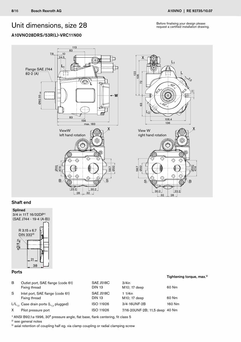
Unit dimensions, size 28A10VNO28DRS/53R(L)-VRC11N00
Before finalising your design please request a certified installation drawing.
Ports Tightening torque, max.2)
B Outlet port, SAE flange (code 61) Fixing thread
SAE J518C DIN 13
3/4in M10; 17 deep
60 Nm
S Inlet port, SAE flange (code 61) Fixing thread
SAE J518C DIN 13
1 1/4in M10; 17 deep
60 Nm
L/L1,2 Case drain ports (L1,2 plugged) ISO 11926 3/4-16UNF-2B 160 Nm
X Pilot pressure port ISO 11926 7/16-20UNF-2B; 11,5 deep 40 Nm
1) ANSI B92.1a-1996, 30° pressure angle, flat base, flank centering, fit class 5 2) see general notes 3) axial retention of coupling half eg. via clamp coupling or radial clamping screw
Splined 3/4 in 11T 16/32DP1) (SAE J744 - 19-4 (A-B))
Shaft end
2832
Ø32
58.7
Ø20
47.6
22.230.2
61.5
61.5
2.5
45°
45°
11
106.4136
6372
122
106
24.57.8 10
83156
max. 183
83113
Ø82
.55
h8
S B
L
X
X
L2
L1
L
L1
W
28 32
Ø32
58.7
Ø20
47.6
22.2 30.2
SB
X
Flange SAE J744 82-2 (A)
ViewW left hand rotation
View W right hand rotation
21
38
ø3/4
in
R 3.15 x 6.7DIN 3323)
RE 92735/10.07 | A10VNO Bosch Rexroth AG 9/16
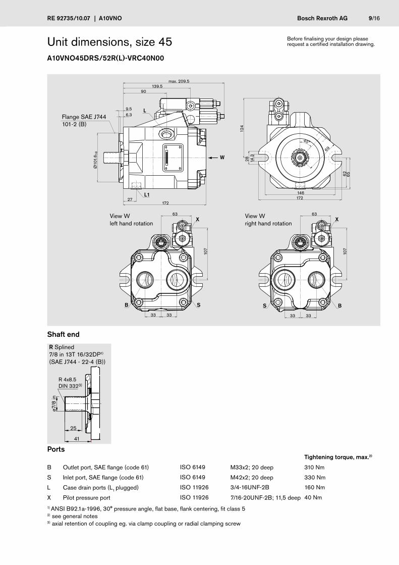
Unit dimensions, size 45A10VNO45DRS/52R(L)-VRC40N00
Ports Tightening torque, max.2)
B Outlet port, SAE flange (code 61) ISO 6149 M33x2; 20 deep 310 Nm
S Inlet port, SAE flange (code 61) ISO 6149 M42x2; 20 deep 330 Nm
L Case drain ports (L1 plugged) ISO 11926 3/4-16UNF-2B 160 Nm
X Pilot pressure port ISO 11926 7/16-20UNF-2B; 11,5 deep 40 Nm
1) ANSI B92.1a-1996, 30° pressure angle, flat base, flank centering, fit class 5 2) see general notes 3) axial retention of coupling eg. via clamp coupling or radial clamping screw
Before finalising your design please request a certified installation drawing.
B S
L
L1
X
BS
X
Ø10
1.6
h8
172
124
90
9.5
max. 209.5
45°
69
27
3333
6.3
14.3
28
62 65
139.5
107
63
3333
107
63
146172
W
Flange SAE J744 101-2 (B)
R Splined 7/8 in 13T 16/32DP1) (SAE J744 - 22-4 (B))
Shaft end
View W right hand rotation
R 4x8.5DIN 3323)
25
41
ø7/8
in
View W left hand rotation
10/16 Bosch Rexroth AG A10VNO | RE 92735/10.07
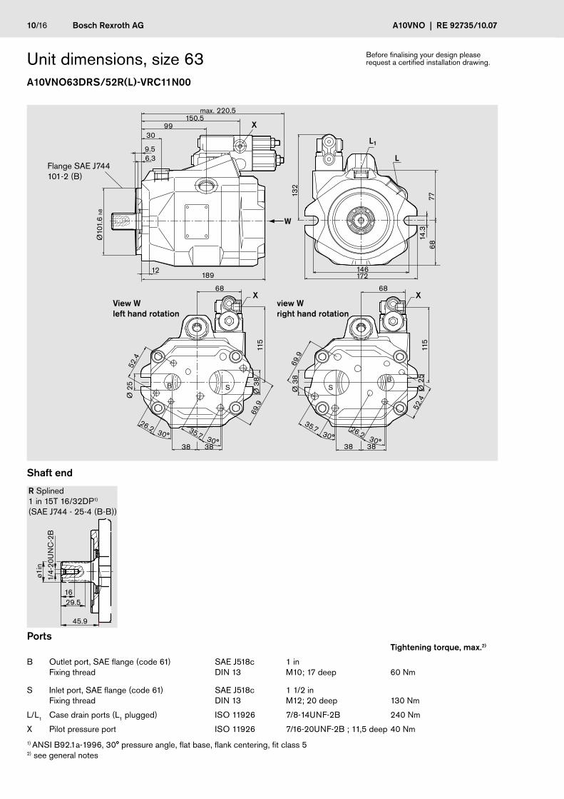
R Splined 1 in 15T 16/32DP1) (SAE J744 - 25-4 (B-B))
Unit dimensions, size 63A10VNO63DRS/52R(L)-VRC11N00
Ports Tightening torque, max.2)
B Outlet port, SAE flange (code 61) Fixing thread
SAE J518c DIN 13
1 in M10; 17 deep
60 Nm
S Inlet port, SAE flange (code 61) Fixing thread
SAE J518c DIN 13
1 1/2 in M12; 20 deep
130 Nm
L/L1 Case drain ports (L1 plugged) ISO 11926 7/8-14UNF-2B 240 Nm
X Pilot pressure port ISO 11926 7/16-20UNF-2B ; 11,5 deep 40 Nm
1) ANSI B92.1a-1996, 30° pressure angle, flat base, flank centering, fit class 5 2) see general notes
Before finalising your design please request a certified installation drawing.
max. 220.5150.5
146172
6868
3838
26.2
26.235.735.7 30°
30°
383830°
30°
115
115
Ø 2
5
Ø 3
8
Ø 3
8
52.4Ø
25
52.4
69.9
69.9
X
L1
L
W
XX
9930
9.56.3
Ø10
1.6
h8
132
7768
14.3
12189
View W left hand rotation
Flange SAE J744 101-2 (B)
Shaft end
view W right hand rotation
1629.5
45.9
ø1in
1/4-
20U
NC
-2B
RE 92735/10.07 | A10VNO Bosch Rexroth AG 11/16
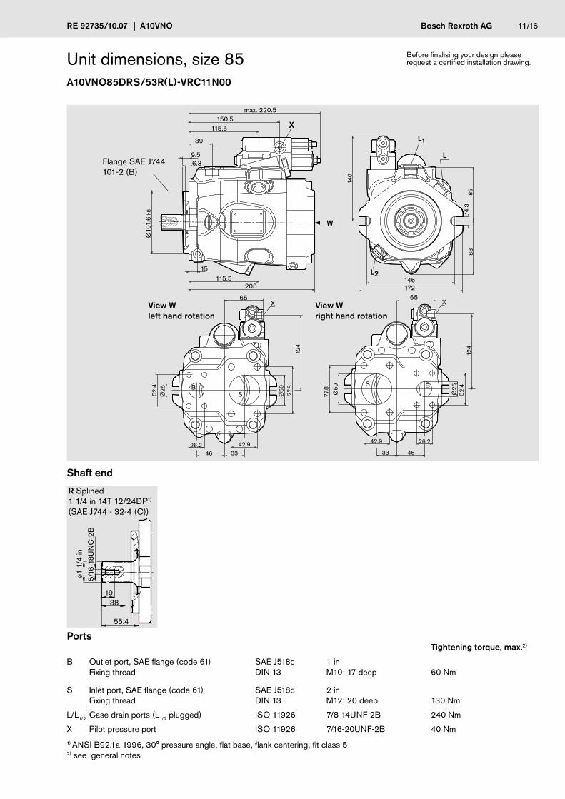
R Splined 1 1/4 in 14T 12/24DP1) (SAE J744 - 32-4 (C))
Shaft end
Unit dimensions, size 85A10VNO85DRS/53R(L)-VRC11N00
Ports Tightening torque, max.2)
B Outlet port, SAE flange (code 61) Fixing thread
SAE J518c DIN 13
1 in M10; 17 deep
60 Nm
S Inlet port, SAE flange (code 61) Fixing thread
SAE J518c DIN 13
2 in M12; 20 deep
130 Nm
L/L1/2 Case drain ports (L1/2 plugged) ISO 11926 7/8-14UNF-2B 240 Nm
X Pilot pressure port ISO 11926 7/16-20UNF-2B 40 Nm
1) ANSI B92.1a-1996, 30° pressure angle, flat base, flank centering, fit class 5 2) see general notes
Before finalising your design please request a certified installation drawing.
max. 220.5
X 150.5
115.5
39
9.5 6.3
115.5
46
26.2
33
42.9
4626.2
3342.9
Ø50
Ø50
77.8
65 6512
477
.8
52.4
Ø25
52.4
Ø25
124
140
Ø10
1.6
h8 14.3
8889
L1
L
L2146172208
W
15
View W left hand rotation
Flange SAE J744 101-2 (B)
View W right hand rotation
1938
55.4
ø1 1
/4 in
5/16
-18U
NC
-2B
12/16 Bosch Rexroth AG A10VNO | RE 92735/10.07
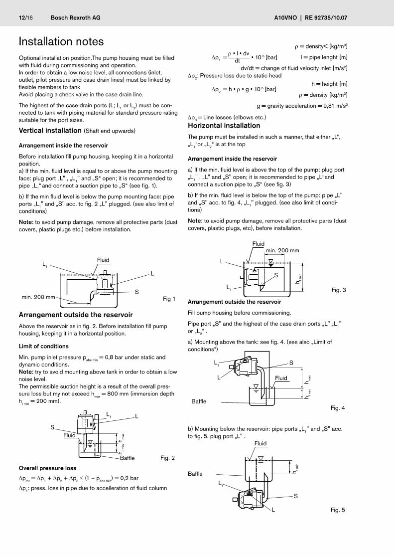
Overall pressure loss
Dptot = Dp1 + Dp2 + Dp3 ≤ (1 – pabs min) = 0,2 bar
Dp1: press. loss in pipe due to accelleration of fluid column
Optional installation position.The pump housing must be filled with fluid during commissioning and operation. In order to obtain a low noise level, all connections (inlet, outlet, pilot pressure and case drain lines) must be linked by flexible members to tank Avoid placing a check valve in the case drain line.
The highest of the case drain ports (L; L1 or L2) must be con-nected to tank with piping material for standard pressure rating suitable for the port sizes.
Vertical installation (Shaft end upwards)
Arrangement inside the reservoir
Before installation fill pump housing, keeping it in a horizontal position. a) If the min. fluid level is equal to or above the pump mounting face: plug port „L" , „L1" and „S“ open; it is recommended to pipe „L1“ and connect a suction pipe to „S“ (see fig. 1).
b) If the min fluid level is below the pump mounting face: pipe ports „L1" and „S" acc. to fig. 2 „L" plugged. (see also limit of conditions)
Note: to avoid pump damage, remove all protective parts (dust covers, plastic plugs etc.) before installation.
Horizontal installationThe pump must be installed in such a manner, that either „L“, „L1“or „L2“ is at the top
Arrangement inside the reservoir
a) If the min. fluid level is above the top of the pump: plug port „L1" , „L" and „S" open; it is recommended to pipe „L“ and connect a suction pipe to „S“ (see fig. 3)
b) If the min. fluid level is below the top of the pump: pipe „L" and „S" acc. to fig. 4, „L1" plugged. (see also limit of condi-tions)
Note: to avoid pump damage, remove all protective parts (dust covers, plastic plugs, etc), before installation.
Arrangement outside the reservoir
Fill pump housing before commissioning.
Pipe port „S" and the highest of the case drain ports „L" „L1" or „L2“ .
a) Mounting above the tank: see fig. 4. (see also „Limit of conditions“)
Arrangement outside the reservoirAbove the reservoir as in fig. 2. Before installation fill pump housing, keeping it in a horizontal position.
Limit of conditions
Min. pump inlet pressure pabs min = 0,8 bar under static and dynamic conditions. Note: try to avoid mounting above tank in order to obtain a low noise level. The permissible suction height is a result of the overall pres-sure loss but my not exceed hmax = 800 mm (immersion depth ht min = 200 mm).
Installation notes
Fig. 3
L
L1
S
Fluid
h t min
Fig. 4
S
L
L1
Baffle
Fluid
h t min
h max
L
S
L1
Baffle
Fluid
h t min
Fig. 5
Fig. 2
S
L1 L
h t min
h max
Baffle
Fluidb) Mounting below the reservoir: pipe ports „L1" and „S" acc. to fig. 5, plug port „L" .
Dp1 = • 10-5 [bar]
Dp2: Pressure loss due to static head
Dp2 = h • r• g • 10-5 [bar]
Dp3 = Line losses (elbows etc.)
Fig 1
L
L1
S
Fluid
r= density< [kg/m3]
l = pipe lenght [m]
dv/dt = change of fluid velocity inlet [m/s2]
r• l • dv dt
h = height [m]
r= density [kg/m3]
g = gravity acceleration = 9,81 m/s2
min. 200 mm
min. 200 mm

Notes
RE 92735/10.07 | A10VNO Bosch Rexroth AG 13/16

Notes
14/16 Bosch Rexroth AG A10VNO | RE 92735/10.07

Notes
RE 92735/10.07 | A10VNO Bosch Rexroth AG 15/16
16/16 Bosch Rexroth AG A10VNO | RE 92735/10.07
Bosch Rexroth AG HydraulicsProduct Segment Axial Piston UnitsPlant Horb An den Kelterwiesen 1472160 Horb a.N., Germany Telephone +49 (0) 74 51 - 92 0 Facsimile +49 (0) 74 51 - 82 [email protected] www.boschrexroth.com
© This document, as well as the data, specifications and other informations set forth in it, are the exclusive property of Bosch Rexroth AG. Without their consent it may not be reproduced or given to third parties.
The data specified above only serve to describe the product. No statements concerning a certain condition or suitability for a certain application can be de-rived from our information. The information given does not release the user from the obligation of own judgment and verification. It must be remembered that our products are subject to a natural process of wear and aging.
Subject to change.
General notes–The pump A10VNO was designed for operation in open loop circuits.
– Systems design, installation and commissioning require trained technicians or tradesmen.
– All hydraulic ports can only be used for the fastening of hydraulic service lines.
– During and shortly after operation of a pump the housing can be extremely hot, avoid being burned. Wear protective clothing. –
– Depending on the operating conditions of the axial piston unit (operating pressure, fluid temperature) deviations from the opera-ting curves can occur.
– Tightening torques: The tightening torques mentioned in this data sheet are maximum values and must not be exceeded (Maxi-mum values for thread in the castings). Manufacturers information concerning the maximum permitted tightening torques of the various fittings is to be observed! For DIN 13 mounting bolts, we recommend that tightening torques be checked on a case by case basis in accordance with VDI 2230 published 2003.
All data, information and instructions mentioned in this data sheet must be adhered to.