
Avoiding Catastrophes in Dynamic Positioning
8
Copyright 2002, IADC/SPE Dril ling Conference This paper was prepared for presentation at the IADC/SPE Drilling Conference held in Dallas, Texas, 26–28 February 2002. This paper was selected for presentation by an IADC/SPE Program Committee following review of information contained in an abstract submitted by the author(s). Contents of the paper, as presented, have not been reviewed by the International Association of Drilling Con- tractors or the Society of Petroleum Engineers and are subject to correction by the author(s). The material, as presented, does not necessarily reflect any position of the IADC or SPE, their officers, or members. Papers presented at the IADC/SPE meetings are subject to publication review by Editorial Committees of the IADC and SPE. Electronic reproduction, distribution, or storage of any part of this paper for commercial purposes without the written consent of the Society of Petroleum Engineers is prohibited. Permission to reproduce in print is restricted to an abstract of not more than 300 words; illustrations may not be copied. The abstract must contain conspicuous acknowledgment of where and by whom the paper was presented. Write Librarian, SPE, P.O. Box 833836, Richardson, TX 75083-3836, U.S.A., fax 01-972-952-9435. Abstract Recent newbuild and major upgrade deep water Dynamically Positioned (DP) rigs have been plagued by station-keeping difficulties. Many of thes e problems ha ve been attributed to the DP system, the power management system, or the DP operators’ capabilities. Maximum efficiency and minimum non-productive (down) time for DP rigs can best be achieved by using an approach that considers all of these factors simul- taneously – a SYSTEMS approach. DP operation successes and failures will be illustrated using case studies from five drilling rigs with which the author has personal experience. Each of these case s will demonstrate the inter-dependence of critical equipment and systems that allow a rig to maintain position. Additionally, the paper will describe latent problems identified, as well as describe why a systems approach would have avoided them. Primary emphasis will be on the symbi- otic relationship between the DP and power plant management control systems, as well as the resident anti-blackout software in both. Cases will illustrate: 1. Who’s right, DP or power management? 2. The DP rabbit and power plant turtle. 3. How lack of DP o perator knowledge can defeat even the smartest software. 4. When does too much redundancy reduce reliability? 5. What happens when one computer doesn’t notice the other one died, or why is it critical that BOTH systems be designed as parts of a whole? Finally, a brief analysis will offer how to best implement the systems approach on future projects, from both the owner and operator viewpoints. The analysis will cover how the systems approach impacts the following: • Making certain that lessons from prior catastrophes are incorporated in the current project • Utilizing the relative strengths of in-house and third party personnel • Understanding effective DP operator training • Enhancing troubleshooting and downtime avoidance Definitions And Clarifications DP – Dynamic Positioning System. A control system that operates propellers, referred to as thrusters in this paper, to maintain a specified location in relation to the well. DPO - DP Operator. An individual who operates the DP system. PMS, VMS or DMS – Power Management System, Vessel Management System or Data Management System. Another name for the Power Management System. A control s ystem that monitors various electrical and other operational parame- ters around the rig, and starts and stops main generator skids. ECR – Engine Control Room. The control room where the VMS controls are located, plus manual controls for diesel engines and generators. For the purpose of this paper, the following simplifications of power terms may aid understanding by the readers. Power. Power is the term used for the horsepower of the die- sel driving a generator, the kW of the generator, or the kW of a motor turning a propeller or rotating the pipe. The effi- ciency of each of these devices normally must be considered when looking at power management. For this paper, however, all devices efficiencies are assumed to be included in power calculations. kW – Kilowatts – 1,000 Watts. A measure of power. IADC/SPE 74504 Avoiding Catastrophes in Dynamic Positioning; Integrating Key Parameters Using a Systems Approach Lew Weingarth/West Hou, Inc
-
Upload
vinicius-garofalo -
Category
Documents
-
view
231 -
download
0
Transcript of Avoiding Catastrophes in Dynamic Positioning

7/27/2019 Avoiding Catastrophes in Dynamic Positioning
http://slidepdf.com/reader/full/avoiding-catastrophes-in-dynamic-positioning 1/8
Copyright 2002, IADC/SPE Drilling Conference
This paper was prepared for presentation at the IADC/SPE Drilling Conference held in Dallas,Texas, 26–28 February 2002.
This paper was selected for presentation by an IADC/SPE Program Committee followingreview of information contained in an abstract submitted by the author(s). Contents of thepaper, as presented, have not been reviewed by the International Association of Drilling Con-tractors or the Society of Petroleum Engineers and are subject to correction by the author(s).The material, as presented, does not necessarily reflect any position of the IADC or SPE, their officers, or members. Papers presented at the IADC/SPE meetings are subject to publicationreview by Editorial Committees of the IADC and SPE. Electronic reproduction, distribution, or
storage of any part of this paper for commercial purposes without the written consent of theSociety of Petroleum Engineers is prohibited. Permission to reproduce in print is restricted toan abstract of not more than 300 words; illustrations may not be copied. The abstract mustcontain conspicuous acknowledgment of where and by whom the paper was presented. WriteLibrarian, SPE, P.O. Box 833836, Richardson, TX 75083-3836, U.S.A., fax 01-972-952-9435.
Abstract
Recent newbuild and major upgrade deep water DynamicallyPositioned (DP) rigs have been plagued by station-keepingdifficulties. Many of these problems have been attributed tothe DP system, the power management system, or the DPoperators’ capabilities. Maximum efficiency and minimumnon-productive (down) time for DP rigs can best be achieved by using an approach that considers all of these factors simul-
taneously – a SYSTEMS approach.
DP operation successes and failures will be illustratedusing case studies from five drilling rigs with which the author has personal experience. Each of these cases will demonstratethe inter-dependence of critical equipment and systems thatallow a rig to maintain position.
Additionally, the paper will describe latent problemsidentified, as well as describe why a systems approach wouldhave avoided them. Primary emphasis will be on the symbi-otic relationship between the DP and power plant managementcontrol systems, as well as the resident anti-blackout software
in both. Cases will illustrate:
1. Who’s right, DP or power management?2. The DP rabbit and power plant turtle.3. How lack of DP operator knowledge can defeat even
the smartest software.4. When does too much redundancy reduce reliability?5. What happens when one computer doesn’t notice the
other one died, or why is it critical that BOTHsystems be designed as parts of a whole?
Finally, a brief analysis will offer how to besimplement the systems approach on future projects, from boththe owner and operator viewpoints. The analysis will covehow the systems approach impacts the following:
• Making certain that lessons from prior catastrophesare incorporated in the current project
•
Utilizing the relative strengths of in-house and third party personnel
• Understanding effective DP operator training
• Enhancing troubleshooting and downtime avoidance
Definitions And Clarifications
DP – Dynamic Positioning System. A control system thaoperates propellers, referred to as thrusters in this paper, tomaintain a specified location in relation to the well.
DPO - DP Operator. An individual who operates the DPsystem.
PMS, VMS or DMS – Power Management System, VesseManagement System or Data Management System. Anothername for the Power Management System. A control systemthat monitors various electrical and other operational parame-ters around the rig, and starts and stops main generator skids.
ECR – Engine Control Room. The control room where theVMS controls are located, plus manual controls for dieseengines and generators.
For the purpose of this paper, the following simplifications of power terms may aid understanding by the readers.
Power. Power is the term used for the horsepower of the diesel driving a generator, the kW of the generator, or the kW oa motor turning a propeller or rotating the pipe. The efficiency of each of these devices normally must be consideredwhen looking at power management. For this paper, howeverall devices efficiencies are assumed to be included in power calculations.
kW – Kilowatts – 1,000 Watts. A measure of power.
IADC/SPE 74504
Avoiding Catastrophes in Dynamic Positioning; Integrating Key Parameters Using aSystems ApproachLew Weingarth/West Hou, Inc
7/27/2019 Avoiding Catastrophes in Dynamic Positioning
http://slidepdf.com/reader/full/avoiding-catastrophes-in-dynamic-positioning 2/8
2 LEW WEINGARTH IADC/SPE 74504
MW – Megawatts – 1,000 kW.
Power Factor (pf) – Power factor measures the phase relation-ship between voltage and current in an electrical device. Putmore simply, power factor measures what percentage of electrical energy is actually performing work. In practice, DCrigs normally see pf in the range 0.4 - 0.8 and AC rigs
normally see pf in the range 0.8 - 0.9.
Overview
Frequently, rigs experience difficulties in holding position, or station. This can occur even after extensive testing of the DPsystem, and, after receiving validations that “all systems areacceptable”. If a systems approach that integrates allshipboard systems and insists on qualified DPOs is not used, problems can be expected to occur. The integrated systemsapproach prioritizes and balances the objectives of eachsystem such that the component systems do not compete. Thenon-integrated case studies in the remaining sections of this paper describe a variety of problems that has occurred. It will be shown how an integrated systems approach may beemployed to eliminate the identified problems.
Consider the three major systems that may beintegrated for a successful systems approach: 1) the DPsystem, 2) the Drilling system, and 3) the power plantresponsible for delivering power to each of them, i.e. the power management system.
1. The DP system objective, simply stated, is tomaintain position in any weather condition encountered. Toaccomplish this objective, the system controls the thrusters sothat they maintain the heading and position of the vessel in
response to set-point heading and position commands. TheseDP system commands dynamically position the vessel relativeto the wellhead. Normally five to eight thrusters can beindividually controlled to supply thrust at any angle bycommanding power to the thruster motors from 0 to 100% atany azimuth. Heading is the primary control variable becauseof its impact on the power required to maintain position.Changes of as little as 5% in heading can require as much as30% more power to operate, depending on the shape of thevessel. Other input parameters include wind speed anddirection, the gyrocompass, and a vertical reference unit.
The vessel position relative to the wellhead is
determined by an acoustic position reference system that has a beacon/transponder array on the sea floor. Another positionreference is supplied by GPS (Global Positioning System). Of course, redundant references as well as control systems areused to improve reliability. With this number of control parameters, it is easy to understand the sophistication of theDP system.
One key feedback parameter related to the drillingoperation is supplied by the BOP MUX system. This is the
angle, or tilt from vertical, of the first joint of riser above theBOP. For proper drilling operations, this angle is normallyminimized in order to reduce wear on the subsea equipmentand insure the ability to disconnect the LMRP (Lower MarineRiser Package) in emergencies. The vessel position setpoint ischanged based on this angle. . This is normally a DPOfunction. This setpoint change is necessary because o
changes in offset (difference between vessel and the wellheadcenterline), current, depth, mud weight, riser tension, etcaffect the non-linearity of the riser
2. The drilling operation, i.e., rotating pipe, liftinglowering, and making up drill pipe and casing strings pumping mud, etc., requires widely varying amounts o power. It is the responsibility of the driller to recognize the power requirements of these operations and to ensure that the power plant can deliver what is needed to execute theoperator’s program as quickly and efficiently as possibleThis is accomplished by their selection of SCR (SiliconControlled Rectifier) assignments of the drilling equipment.
3. Six to twelve diesel powered generators deliver power for the vessel. Each generator has individual controlsto ensure operation within their mechanical envelope. Theseindividual control systems feed specific data to the powermanagement system (PMS). The DP system also feedsspecific data to the PMS. The PMS sends power outpusetpoints to each generator as well as power status data to theDP system.
Some believe that having multiple, and separate power systems, or busses can increase the reliability of the power plant. Both generators and loads are placed tominimize catastrophes when individual equipment fails.
The latest generation of rigs have PMS/VMS/DMShereafter referred to as simply VMS. This system takessignals from each of these three control systems. (DP, BOPand VMS) and manages conflicts. To the extent that this isdone with the understanding of the capabilities, limitationsand requirements of each system, this represents the state-ofthe-art systems approach.
The VMS performs the power management functionmonitoring individual generator loads and preventing blackouts by constantly telling the DP and the drilling systemcomputers how much power is available. It will then allocate
power, including rationing, or “phase back”. Correctlydesigned and operated, this system is effective at preventing blackouts better than each individual system by itself.
Although the control objectives of the three systems provided above are relatively straightforward, it is not difficultto imagine the complications that are introduced whenintegrating them all.
7/27/2019 Avoiding Catastrophes in Dynamic Positioning
http://slidepdf.com/reader/full/avoiding-catastrophes-in-dynamic-positioning 3/8
AVOIDING CATASTROPHES IN DYNAMIC POSITIONING; INTEGRATING KEYIADC/SPE 74504 PARAMETERS USING A SYSTEMS APPROACH 3
Case Studies
Case 1: Who’s Right, DP Or Power Management?
A DP drillship was upgraded in 1997 with a new DP andVMS.
The DP software on this rig is responsive and powerful. The DP software includes many features that allowa talented DPO to adjust for best performance and minimaloperating cost in anything from calm seas to hurricanes.These features, if set correctly, prevent a drive off duringnormal drilling operations. They can also be adjusted toenhance safety and station keeping in a hurricane.
DPOs on this rig are selected from personnel who donot have training in closed loop control system or power planttheory. In this case, the DPOs set the DP power limitincorrectly.
In the first operational state described below, headingchanges caused the DP system to use all the available power and phase back the driller, even though plenty of power wasavailable for both functions. This was demonstrated by theoperation illustrated in the second plot
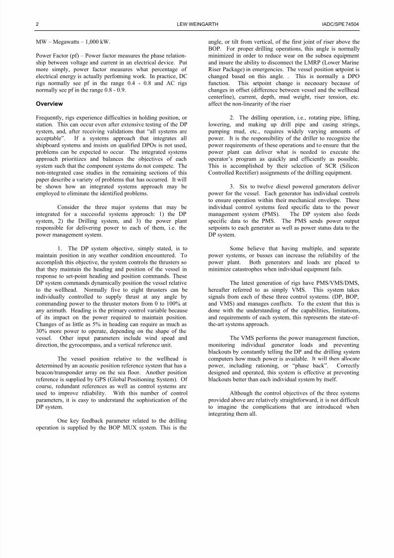
Consider Figure 1 and Figure 2. Both display 20seconds of time. The only difference between them is thesetting of the DP power limit. Figure 1 shows a 5 degreeheading change with the DP power limit set at maximum. TheDP system uses all the available power for a few seconds tostart the ship turning, after which power consumption dropsoff to the level before the turn started. Notice the blue line
describing the drilling load. The topdrive and mud pumpsnearly stopped for a few seconds when the DPO entered theheading change.
Figure 1
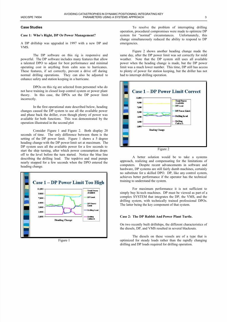
To resolve the problem of interrupting drillingoperation, procedural compromises were made to optimize DPsystem for “normal” circumstances. Unfortunately, thischange simultaneously reduced the ability to respond to DPemergencies.
Figure 2 shows another heading change made thesame day, after the DP power limit was set correctly for mildweather. Note that the DP system still uses all available power when the heading change is made, but the DP powelimit was a much lower number. This time, DP still has accesto plenty of power for station keeping, but the driller has nohad to interrupt drilling operation.
Figure 2
A better solution would be to take a systemsapproach, realizing and compensating for the limitations ofcomputers. Despite recent advancements in software andhardware, DP systems are still fairly dumb machines, certainlyno substitute for a skilled DPO. DP, like any control systemachieves better performance if the operator has the technicaltraining to understand the system.
For maximum performance it is not sufficient tosimply buy hi-tech machines. DP must be viewed as part of acomplex SYSTEM that integrates the DP, the VMS, and thedrilling system, with technically trained professional DPOsThe latter being the key component of that system.
Case 2: The DP Rabbit And Power Plant Turtle.
On two recently built drillships, the different characteristics ofthe diesels, DP, and VMS resulted in several blackouts.
The diesels on these vessels are of a type that isoptimized for steady loads rather than the rapidly changingdrilling and DP loads required for drilling operation.
7/27/2019 Avoiding Catastrophes in Dynamic Positioning
http://slidepdf.com/reader/full/avoiding-catastrophes-in-dynamic-positioning 4/8
4 LEW WEINGARTH IADC/SPE 74504
DP system adjusts thrust twice per second, limited bya “power available” number that it receives from the VMS.VMS runs much slower than DP, updating the “power available” figure every two seconds.
Although the DP system knew the total power available, it would demand power at a faster rate than the
diesels could deliver. For example, even though the DP power demand never exceeded 100% of the generators’ capacity, itmight change from 50% load to 90% load twice as fast as thediesels could ramp up, causing them to slow down andshut down.
On the next update, the VMS would ramp down the“power available” signal to the DP system to protect thediesels. Unfortunately, this was after the rig had already blacked out.
Similar to case study #1, this rig had adjustable DP power limits. Also, like the original operating scenario incase #1, these limits were set too high.
A fairly simple, though somewhat clumsy, solutionwas found. The VMS software was modified to simply shutoff all the thrusters for two seconds when it detected the dieselengines slowing down. During the two-second hiatus, itrecalculated the “power available” signal to send to DP. This prevented blackouts with only a minimal affect on stationkeeping performance, or so it was thought. What doesshutting all power off to thrusters do to power plant load, particularly when following it up with a higher demand?
The problem could have been avoided with a systemsapproach. A systems approach would have specified one or
more of the following:
1. Diesels that can follow rapid changes in demand.2. A DP power ramp that matched the capability of the
diesels.3. A faster VMS system; one that could control the
“power available” signal to DP in real time.4. DPOs with an understanding of power plant theory,
who could adjust the DP power limits to avoid the problem entirely.
Case 3: How Lack Of DP Operator Understanding Can
Defeat Even The Smartest Software.
This case is a follow on to case 2. The VMS software had been modified to drop the thrusters whenever a blackout was pending. This prevented blackouts, but failed to consider allscenarios.
On location one night the weather was very calm.The seas were flat and the wind about 15 knots. The dieselswere running at about 40% load. There was 16 MW of generator capacity online, with a total load of 7 MW, 3 MW of
DP load and 4 MW in use by other shipboard systems. TheDP power limit was set at maximum.
The DPO made a 30-degree heading change. Whenhe entered the heading change, the DP system quickly rampedthe thrusters up to 6 MW. The main engines could not provide power this fast so they slowed down, which resulted in a
decrease of the frequency. VMS noticed the slowdown andshut off all thrusters for two seconds. This reduced the loadon the power plant, but made DP fall behind on thecommanded turn. When power returned two seconds later, DPallocated even more power than the previous time, whichresulted in the diesels again overloading and another thrustershut down by VMS. This cycle repeated four times before therig finally reached the commanded heading, and thrustercommand dropped below a level the diesels could supply.
At no time did the DP operator make any attempt tomitigate the problem, and when questioned afterwardsemphatically stated that “it was a power plant problem andhad nothing to do with DP”.
This problem results when one views the diesels, DPVMS, and DPOs as separate issues. Had all of these systems been integrated by using a systems approach, this event wouldnot have occurred. In this example, a weak coordination odiesels, DP, and VMS was defeated by DPO lack of technicaunderstanding.
Case 4: When Does Too Much Redundancy Reduce Reli-
ability?
DP drilling rigs are all built to either classification DP 2 orDP 3. What do these classifications mean?
DP 2 classification indicates equipment redundancy –loss of any piece of equipment will not cause loss of stationkeeping ability.
DP 3 classification indicates compartmenredundancy – loss of any compartment will not cause loss ofstation keeping ability.
It would seem that DP 3 is superior to DP 2. Beingable to survive the loss of an entire compartment is prettyimpressive. However, DP 3 operation often can provide lessreliability than DP 2.
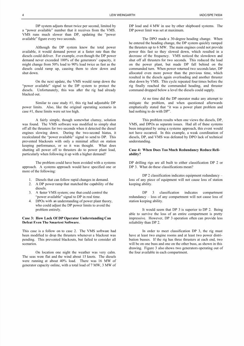
In order to meet classification DP 3, the rig musthave at least two engine rooms and at least two power distri- bution busses. If the rig has three thrusters at each end, twowill be on one buss and one on the other buss, as shown in thisdrawing. Figure 3 also shows two generators operating out othe four available in each compartment.
7/27/2019 Avoiding Catastrophes in Dynamic Positioning
http://slidepdf.com/reader/full/avoiding-catastrophes-in-dynamic-positioning 5/8
AVOIDING CATASTROPHES IN DYNAMIC POSITIONING; INTEGRATING KEYIADC/SPE 74504 PARAMETERS USING A SYSTEMS APPROACH 5
Figure 3
With eight 4.5 MW generators and six 5 MWthrusters this looks like a safe situation. The 7.8 MW thruster load is less than half of the 18 MW capacity of 4 generators,and less than the 9 MW capability now operating in oneengine room. Let’s look closer.
If the starboard engine room fails, the rig will losestation even though plenty of power is available. The problemis that two of the three forward thrusters will stop, requiringthe one remaining 5 MW forward thruster to supply 5.4 MWof thrust, which it cannot do. This is graphically depicted inFigure 4:
Figure 4
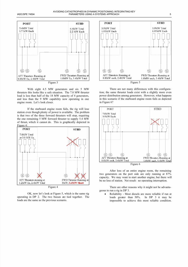
OK, now let’s look at Figure 5, which is the same rigoperating in DP 2. The two busses are tied together. Theloads are the same as the previous scenario.
Figure 5
There are not many differences with this configura-tion; the same thruster loads exist with a slightly more even power distribution among generators. However, what happensin this scenario if the starboard engine room fails as depictedin Figure 6?
Figure 6
After loss of an entire engine room, the remaining
two generators on the port side are only running at 87%capacity. We may want to start another engine, but there wil be no loss of station. Net result: no operating interruption.
There are other reasons why it might not be advanta-geous to run a rig in DP 3.
• Reliability - Most diesels are more reliable if run aloads greater than 50%. In DP 3 it may beimpossible to achieve this most reliable condition
7/27/2019 Avoiding Catastrophes in Dynamic Positioning
http://slidepdf.com/reader/full/avoiding-catastrophes-in-dynamic-positioning 6/8
6 LEW WEINGARTH IADC/SPE 74504
Up to rated capacity, higher generator loads generallymeans less maintenance and downtime.
• Maintenance - Thrusters and diesels require periodicmaintenance. If operating in DP 3, shutting downany engine or thruster removes a greater percentageof backup capability, compared to operating in DP 2.
• Fault clearing - If a generator faults, the remaining
units must be able to provide sufficient current toopen the breaker(s). One generator may not besufficient to open the breaker. If not, this wouldrequire running three generators on each bussregardless of power consumption, which would in-crease downtime.
However, operating in DP 2 mode is not withoutoffsetting risk. The rig must make sure that the protectiverelays are set up correctly and tested regularly. Likewise, power management must be coordinated throughout all therig systems.
Case 5. What Happens When One Computer Doesn’tNotice The Other One Died.
The Sedco/BP 471 has been in continuous operation as a DPDrillship since 1978.
Until a recent upgrade, the computer systems on thisrig used 1970 technology. This case study considers the rigfrom 1978 – 2001, before the recent upgrade.
The DP and VMS computers run independently of each other, with the only shared data being the time and date.The DP system monitors power consumption by the thrustersand drilling systems, and limits thrust according to acalculation of available power, in compliance with parametersset by the DPO. The VMS simply monitored engine load andstarted more engines as needed.
The equipment failure rate on this rig was at leastequal to modern drillships, but the Sedco/BP 471 has movedoff location in excess of 2% of water depth only one timesince 1984. As with almost all losses of location, that eventwas the result of human error, and preventable.
Why does this old DP rig perform so much better than the new DP rigs? The 471 has a major advantage over modern DP rigs. The rig owner took a systems approach
during design, construction, and manning. The view of thevessel as a SYSTEM was carried through into every phaseof operation.
Specialists in engine control room (ECR) operationwere hired to man the engine control console. The ECR wasset up to allow complete and easy manual operation in case of computer failure. Since DP took care of preventing blackouts,
it was relatively easy for the ECR watchstander to keepenough power on line.
The DPOs were degreed Electrical Engineers, highlytrained and skilled in power plant theory, electronics, andclosed loop control system theory. The DP room was isolatedfrom the rest of the rig, and entrance restricted, allowing the
DPOs to concentrate on DP.
During an emergency it is often critical to diagnosetechnical problems in seconds to prevent losing location. Thequiet operating environment and technical expertise of theDPOs prevented many driftoffs over the years.
So back to the original question: what happens whenthe DP system doesn’t notice the VMS computer has died?
The DPO gets an alarm light telling him VMS hasfailed. He makes a mental note to notify the ECR a fewminutes earlier than normal of impending need for more power. The Watchstander in the ECR moves himself and histeapot over to the manual engine control panel.
What happens when the DP system doesn’t notice theVMS computer has died? For all practical purposes nothingworth mentioning happens, because in this case a SYSTEMSAPPROACH was taken from the initial design right through tomanning of the rig. Well-designed backup manual controlsand technically skilled crews provide what the computers lack – understanding of a DP Drilling rig as a SYSTEM.
The track record of this rig speaks well for thesystems approach methodology. This rig, despite operatingabout half the time in areas with storms, surface currents, and
rip tides, has only lost station once in the last 17 years, and noonce in the last decade.
How to Implement the Systems Approach on NewRigs
The best means to assure that a new DP rig will be successfulis to follow a SYSTEMS DESIGN approach from inceptionthrough completion to manning.
In the design stage, all systems that can cause a blackout should be considered simultaneously. The majorcomponents to consider are the main engines, DP, VMS
drilling controls, and DPOs. Each of these sub-systems should be designed to do as much of their own control as possibleThis provides the following benefits:
1. simplifies each system,2. matches performance criteria between all othe
systems, and3. maintains their individual functionality when other
systems fail.
7/27/2019 Avoiding Catastrophes in Dynamic Positioning
http://slidepdf.com/reader/full/avoiding-catastrophes-in-dynamic-positioning 7/8
AVOIDING CATASTROPHES IN DYNAMIC POSITIONING; INTEGRATING KEYIADC/SPE 74504 PARAMETERS USING A SYSTEMS APPROACH 7
Any subsystem that uses enough power to blackoutthe rig should have the ability to monitor the power plant andcontrol its own power usage as needed. This will improvereliability, reduce response time, and simplify troubleshooting.If each subsystem prevents itself from overloading the power plant, blackout will become nearly impossible. The small cost
and size of transducers today, combined with the widespreaduse of PLCs to operate machinery, makes this economicallyand technically feasible.
Additionally, responsive main engines should bechosen. The main selection criteria should be to make sure thediesels and generators can provide the power needed by theDP and drilling systems, at the rate they demand, and at the power factor they create. The engines should only sharethe minimum number of auxiliaries to prevent single point failures.
The DP system should be able to monitor generator load, power factor, frequency, and other important parameters,
not for control of the engines, but to predict problems and prevent blackouts. The DP console should be physicallyseparated from normal operations, in a separate room, so thatthe DPOs can concentrate on operating the DP system.
The VMS should be focussed on starting engines andnot take an active part in DP or Drilling operations. It shouldhave the ability to monitor what DP and the drilling controlsdo in order to predict the need for additional engines.
The drilling controls should also take care of themselves, much as the DP system does. Similar to DP, thedrilling controls should be able to monitor generator load,
power factor, frequency, and other important parameters,again not for control of the engines, but to predict problemsand prevent blackouts.
The DP Operators should be chosen by technicalability. The ideal DPO is one who understands the programming, the computer, all PLCs, networks, and inputsand outputs, plus the thrusters, motors, and generator plants.With this set of skills, coupled with the reliability of modernDP systems, driftoffs should become a thing of the past.Driveoffs, of course, have always been the result of operator error.
The design of all subsystems should be reviewedwith the history of DP vessels in mind. This review shouldinclude internal experts to make sure past problems areavoided. Third party consultants, who can bring in the DPexperience of other companies, should also be included. Aswith most decisions, involving more people will result in a better decision.
Another key to operational success is to make surethat, during the commissioning stage, adequate technical
expertise is applied and that testing is thorough. Thoroughtesting means more than checking each input and output. Imust include blackout recovery and endurance exercises.
A review of project deliverability would suggest thamost drilling construction projects could be better managed
The core business of drilling contractors is drilling, which theydo well. However, construction projects often end up theresponsibility of their operational engineering staff, wheretraining and experience in project management would not beexpected. If the appropriate additional and skilled staff is nohired to cover the added workload, this results in overloadedstaff, increased stress, and reduced performance. Projectswould be more successfully executed if a consulting professional project manager were engaged with the authorityto determine what level of support the existing staff requires.
Given that most drilling contractors don’t havenewbuild or major upgrade projects continuously, the bessolution is probably a mix of outside consultants and internal
expertise. For an additional $7 million, 20 consultingengineers could be hired for a 24-month project. $7 million ia lot of money, until you compare it to the average cosoverrun of new construction DP rig projects.
This methodology is not unknown. All of these ideascome from existing drilling contractors, though no drillingcontractor follows all of them. One drilling contractor followsmost of these ideas. This particular contractor has only onedeepwater rig, but that rig has arguably the best DP and powermanagement performance in the industry. They followed the philosophy of having each subsystem control its own powerand attempting to hire DPOs with the skills to operate a
computerized control system. As a result, that DP rig is practically impossible to black out, and DP performance isexemplary. Unfortunately, this contractor also followed the“industry standard” of understaffing the construction andcommissioning stages, and thus had high initial downtimeThe “lost opportunity” cost most certainly outweighed byorders of magnitude the cost of additional help.
Conclusion
As you can see from this paper, the concept of a systemsapproach to DP design and operation is relatively simple. Theadequate control of individual systems can be complicated
unto themselves, but if each of these dependent systems do notconsider the others, catastrophe is just around the cornerAlthough simple in concept, this systems approach requires amuch higher breadth of knowledge than does the individualis-tic approach. Such individuals are more difficult to findespecially in times of a “building boom” such as recentlyexperienced.

7/27/2019 Avoiding Catastrophes in Dynamic Positioning
http://slidepdf.com/reader/full/avoiding-catastrophes-in-dynamic-positioning 8/8
8 LEW WEINGARTH IADC/SPE 74504
Bonus Observations
For no extra charge, consider the following:
Free hint #1 – If the protective relay coordination, power management design, and commissioning are given proper attention, the rig will probably never have a blackout.
Free hint #2 – If the DPOs are degreed andexperienced electrical engineers from control system backgrounds, the rig will probably never lose location.
Free hint #3 – Find out if the DP and VMS weretested as a unit during sea trials, or separately. I have heardlots of people, even 3rd party surveyors, say “DP was OK but problems in the power management system caused blackouts.”This indicates that acceptance testing didn’t take a systemsview. You cannot separate DP, power management, and DPOskills when surveying or commissioning DP drilling rigs if your desire is to determine fitness for purpose.