AVH517 8516 manual V0.9 - surveillance-download.com · h517(p)_8516_manual_V0.9 H.265 5MP NVR...
80
h517(p)_8516_manual_V0.9 H.265 5MP NVR SERIES User Manual Please read instructions thoroughly before operation and retain it for future reference. Online manual download: www.surveillance-download.com/user/h517.swf
-
Upload
duongduong -
Category
Documents
-
view
242 -
download
1
Transcript of AVH517 8516 manual V0.9 - surveillance-download.com · h517(p)_8516_manual_V0.9 H.265 5MP NVR...

h517(p)_8516_manual_V0.9
H.265 5MP NVR
SERIES
User Manual
Please read instructions thoroughly before operation and retain it for future reference.
Online manual download: www.surveillance-download.com/user/h517.swf
IMPORTANT SAFEGUARD
All lead-free products offered by the company comply with the requirements of the European law on the Restriction of Hazardous Substances (RoHS) directive, which means our manufacture processes and products are strictly “lead-free” and without the hazardous substances cited in the directive.
The crossed-out wheeled bin mark symbolizes that within the European Union the product must be collected separately at the product end-of-life. This applies to your product and any peripherals marked with this symbol. Do not dispose of these products as unsorted municipal waste. Contact your local dealer for procedures for recycling this equipment.
This is a class A product. In a domestic environment this product may cause radio interference in which case the user may be required to take adequate measures.
Federal Communications Commission Interference Statement This equipment has been tested and found to comply with the limits for a Class A digital device, pursuant to Part 15 of the FCC Rules. These limits are designed to provide reasonable protection against harmful interference when the equipment is operated in a commercial environment. This equipment generates, uses, and can radiate radio frequency energy and, if not installed and used in accordance with the instruction manual, may cause harmful interference to radio communications. Operation of this equipment in a residential area is likely to cause harmful interference in which case the user will be required to correct the interference at his own expense.
This device complies with Part 15 of the FCC Rules. Operation is subject to the following two conditions:
(1) This device mat not cause harmful interference, and
(2) This device must accept any interference received, including interference that may cause undesired operation.
Disclaimer iPad and iPhone are trademarks of Apple Inc., registered in the U.S. and other countries. App Store is a service mark of Apple Inc. IOS is a trademark or registered trademark of Cisco in the U.S. and other countries and is used under license.
Google Play and Android are trademarks of Google Inc
We reserve the right to revise or remove any content in this manual at any time. We do not warrant or assume any legal liability or responsibility for the accuracy, completeness, or usefulness of this manual. The content of this manual is subject to change without notice.
This product doesn’t have a standby / off mode.

MPEG4 Licensing THIS PRODUCT IS LICENSED UNDER THE MPEG4 VISUAL PATENT PORTFOLIO LICENSE FOR THE PERSONAL AND NON-COMMERCIAL USE OF A CONSUMER FOR (i) ENCODING VIDEO IN COMPLIANCE WITH THE MPEG4 VISUAL STANDARD (“MPEG-4 VIDEO”) AND/OR (ii) DECODING MPEG4 VIDEO THAT WAS ENCODED BY A CONSUMER ENGAGED IN A PERSONAL AND NON-COMMERCIAL ACTIVITY AND/OR WAS OBTAINED FROM A VIDEO PROVIDER LICENSED BY MPEG LA TO PROVIDE MPEG4 VIDEO. NO LICENSE IS GRANTED OR SHALL BE IMPLIED FOR ANY OTHER USE. ADDITIONAL INFORMATION INCLUDING THAT RELATING TO PROMOTIONAL INTERNAL AND COMMERCIAL USES AND LICENSING MAY BE OBTAINED FROM MPEG LA, LLC. SEE HTTP://WWW.MPEGLA.COM.
GPL Licensing
This product contains codes which are developed by Third-Party-Companies and which are subject to the GNU General Public License (“GPL”) or the GNU Lesser Public License (“LGPL”).
The GPL Code used in this product is released without warranty and is subject to the copyright of the corresponding author.
Further source codes which are subject to the GPL-licenses are available upon request.
We are pleased to provide our modifications to the Linux Kernel, as well as a few new commands, and some tools to get you into the code. The codes are provided on the FTP site, and please download them from the following site or you can refer to your distributor:
http://download.dvrtw.com.tw/GPL/NVR/T-Series/linux.tar.gz

TABLE OF CONTENTS
1. HARDWARE OVERVIEW ................................................................................................................... 1
1.1 Front Panel ................................................................................................................................................ 1
1.2 Rear Panel ................................................................................................................................................ 2
2. CONNECTION .................................................................................................................................... 3
2.1 Hard Disk Installation ................................................................................................................................ 3
2.2 Connection ................................................................................................................................................ 6
2.3 Camera IP Configurations by LAN ............................................................................................................ 7
3. FOR INITIAL USE ............................................................................................................................... 9
3.1 Setup Wizard ............................................................................................................................................. 9
3.2 Mount Hard Disk ...................................................................................................................................... 11
3.3 Change User Name and Password ......................................................................................................... 11
4. USER INTERFACE ........................................................................................................................... 13
4.1 Local Access ........................................................................................................................................... 13
4.2 Interface Overview .................................................................................................................................. 13
4.3 Status & Operation .................................................................................................................................. 14
4.3.1 Device Status ................................................................................................................................................. 14 4.3.2 Channel Status ............................................................................................................................................... 14 4.3.3 Main Menu ...................................................................................................................................................... 15 4.3.4 Playback Panel............................................................................................................................................... 17
5. FREQUENTLY-USED FUNCTIONS ................................................................................................. 18
5.1 IP Device Search ..................................................................................................................................... 18
5.2 User Account Creation ............................................................................................................................ 19
5.3 System Logout ........................................................................................................................................ 20
5.4 PTZ Control ............................................................................................................................................. 20
5.5 Video Backup .......................................................................................................................................... 22
6. MAIN MENU ..................................................................................................................................... 23
6.1 CAMERA ................................................................................................................................................. 23
6.1.1 CONNECTION ............................................................................................................................................... 23 6.1.2 DEVICE .......................................................................................................................................................... 24 5.1.3 IMAGE ............................................................................................................................................................ 25 6.1.4 DETECTION ................................................................................................................................................... 25
6.2 RECORD ................................................................................................................................................. 27
6.3 SCENARIO .............................................................................................................................................. 29
6.3.1 Pre-defined Scenarios .................................................................................................................................... 29 6.3.2 Scenario Customization ................................................................................................................................. 31
6.4 IVS........................................................................................................................................................... 34
6.5 EXPORT .................................................................................................................................................. 37
6.5.1 BACKUP ......................................................................................................................................................... 37 6.5.2 SCHEDULE .................................................................................................................................................... 37 6.5.3 REGULAR REPORT ...................................................................................................................................... 39
6.6 STORAGE ............................................................................................................................................... 40
6.7 ACCOUNT ............................................................................................................................................... 41
6.7.1 USER LIST ..................................................................................................................................................... 41 6.7.2 GROUP .......................................................................................................................................................... 42
6.8 NETWORK .............................................................................................................................................. 43
6.8.1 E-MAIL ........................................................................................................................................................... 43
6.8.2 FTP ................................................................................................................................................................. 44 6.8.3 MULTICASTING ............................................................................................................................................. 44 6.8.4 EaZy ............................................................................................................................................................... 45
6.9 TIME ........................................................................................................................................................ 45
6.10 DISPLAY ............................................................................................................................................... 46
6.11 PERIPHERAL ........................................................................................................................................ 47
6.11.1 LOCAL .......................................................................................................................................................... 48 6.11.2 JOYSTICK .................................................................................................................................................... 49
6.12 MAINTAIN ............................................................................................................................................. 49
6.12.1 SYSTEM ....................................................................................................................................................... 49 6.12.2 UPGRADE .................................................................................................................................................... 50 6.12.3 ALERT .......................................................................................................................................................... 51 6.12.4 EVENT LOG ................................................................................................................................................. 51 6.12.5 ONLINE ........................................................................................................................................................ 52
6.13 POWER CONTROL .............................................................................................................................. 52
6. REMOTE OPERATION ..................................................................................................................... 53
6.2 Web Browser ........................................................................................................................................... 53
6.3 Mobile Devices ........................................................................................................................................ 54
6.3.1 Prerequisites .................................................................................................................................................. 54 6.3.2 Where to download ........................................................................................................................................ 54 6.3.3 Setup .............................................................................................................................................................. 54
APPENDIX 1 PRODUCT SPECIFICATIONS ........................................................................................ 56
APPENDIX 2 PUSH VIDEO CONFIGURATION ................................................................................... 58
A2.1 Alarm Sensor Connection ..................................................................................................................... 58
A2.2 Configuration......................................................................................................................................... 59
A2.2 Enable Push Video ............................................................................................................................... 59
A2.2.1 From iOS Mobile Device (iPhone / iPad) ..................................................................................................... 59 A2.2.2 From Android Mobile Device ........................................................................................................................ 60
APPENDIX 3 COMPATIBLE USB FLASH DRIVE LIST ........................................................................ 61
APPENDIX 4 COMPATIBLE HARD DISK LIST .................................................................................... 62
APPENDIX 5 BATTERY REPLACEMENT ............................................................................................ 63
APPENDIX 6 DISK ARRAY COMPATIBLE LIST ................................................................................... 64
APPENDIX 7 EAZY NETWORKING ..................................................................................................... 65
A8.1 Via EagleEyes on iOS / Android Device ......................................................................................................... 65 A8.2 Via Internet Explorer on PC / Laptop .............................................................................................................. 70 A8.3 Icons ............................................................................................................................................................... 75
HARDWARE OVERVIEW
1
1. HARDWARE OVERVIEW
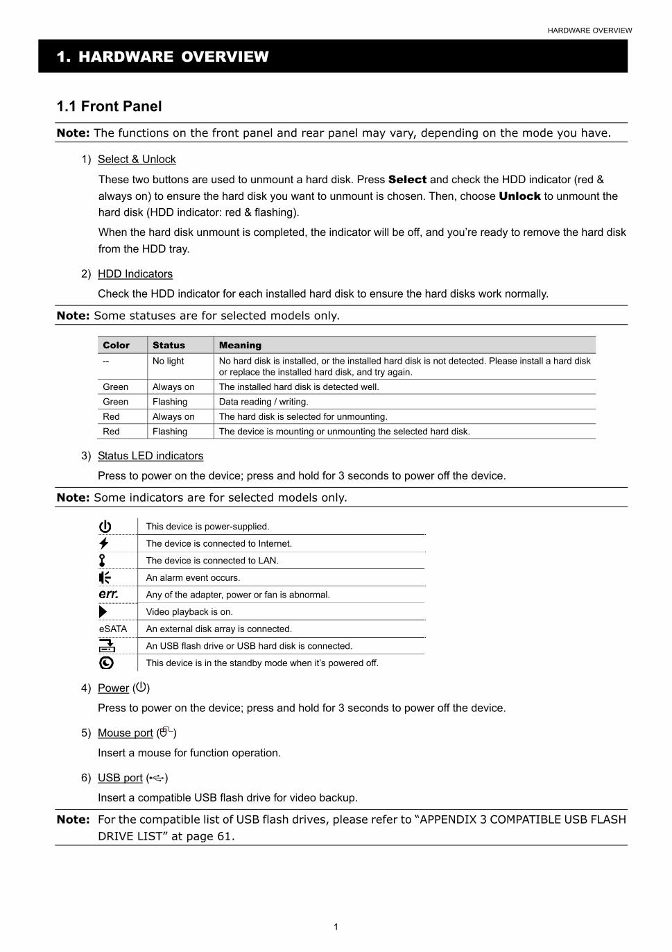
1.1 Front Panel
Note: The functions on the front panel and rear panel may vary, depending on the mode you have.
1) Select & Unlock
These two buttons are used to unmount a hard disk. Press Select and check the HDD indicator (red &
always on) to ensure the hard disk you want to unmount is chosen. Then, choose Unlock to unmount the
hard disk (HDD indicator: red & flashing).
When the hard disk unmount is completed, the indicator will be off, and you’re ready to remove the hard disk
from the HDD tray.
2) HDD Indicators
Check the HDD indicator for each installed hard disk to ensure the hard disks work normally.
Note: Some statuses are for selected models only. Color Status Meaning -- No light No hard disk is installed, or the installed hard disk is not detected. Please install a hard disk
or replace the installed hard disk, and try again.
Green Always on The installed hard disk is detected well.
Green Flashing Data reading / writing.
Red Always on The hard disk is selected for unmounting.
Red Flashing The device is mounting or unmounting the selected hard disk.
3) Status LED indicators
Press to power on the device; press and hold for 3 seconds to power off the device.
Note: Some indicators are for selected models only.
This device is power-supplied.
The device is connected to Internet.
The device is connected to LAN.
An alarm event occurs.
Any of the adapter, power or fan is abnormal.
Video playback is on.
eSATA An external disk array is connected.
An USB flash drive or USB hard disk is connected.
This device is in the standby mode when it’s powered off.
4) Power ( )
Press to power on the device; press and hold for 3 seconds to power off the device.
5) Mouse port ( )
Insert a mouse for function operation.
6) USB port ( )
Insert a compatible USB flash drive for video backup.
Note: For the compatible list of USB flash drives, please refer to “APPENDIX 3 COMPATIBLE USB FLASH DRIVE LIST” at page 61.
HARDWARE OVERVIEW
2
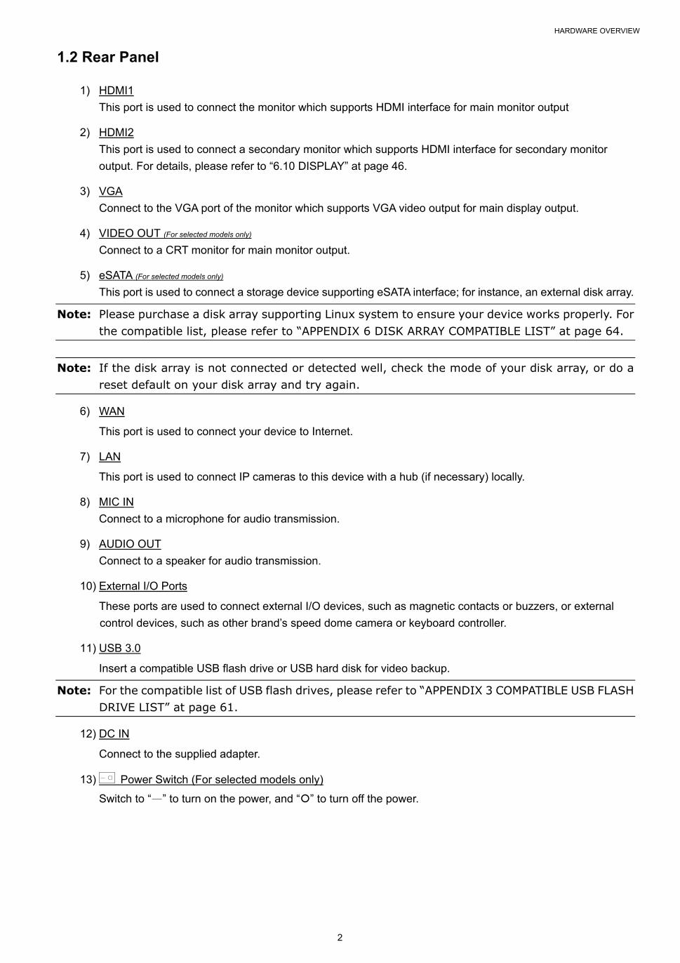
1.2 Rear Panel
1) HDMI1
This port is used to connect the monitor which supports HDMI interface for main monitor output
2) HDMI2
This port is used to connect a secondary monitor which supports HDMI interface for secondary monitor
output. For details, please refer to “6.10 DISPLAY” at page 46.
3) VGA
Connect to the VGA port of the monitor which supports VGA video output for main display output.
4) VIDEO OUT (For selected models only)
Connect to a CRT monitor for main monitor output.
5) eSATA (For selected models only)
This port is used to connect a storage device supporting eSATA interface; for instance, an external disk array.
Note: Please purchase a disk array supporting Linux system to ensure your device works properly. For the compatible list, please refer to “APPENDIX 6 DISK ARRAY COMPATIBLE LIST” at page 64.
Note: If the disk array is not connected or detected well, check the mode of your disk array, or do a reset default on your disk array and try again.
6) WAN
This port is used to connect your device to Internet.
7) LAN
This port is used to connect IP cameras to this device with a hub (if necessary) locally.
8) MIC IN
Connect to a microphone for audio transmission.
9) AUDIO OUT
Connect to a speaker for audio transmission.
10) External I/O Ports
These ports are used to connect external I/O devices, such as magnetic contacts or buzzers, or external
control devices, such as other brand’s speed dome camera or keyboard controller.
11) USB 3.0
Insert a compatible USB flash drive or USB hard disk for video backup.
Note: For the compatible list of USB flash drives, please refer to “APPENDIX 3 COMPATIBLE USB FLASH DRIVE LIST” at page 61.
12) DC IN
Connect to the supplied adapter.
13) Power Switch (For selected models only)
Switch to “—” to turn on the power, and “” to turn off the power.

CONNECTION
3
2. CONNECTION
2.1 Hard Disk Installation
Note: It’s necessary to install a hard disk first before firmware upgrade to ensure the upgrade process works properly.
Type 1
Step1: Remove the top cover, and find the hard disk connector and bracket in the device.
CR2032
Bracket
Hard DiskConnector
BracketScrews
Step2: Get a compatible hard disk. With the PCB side facing down, insert the hard disk to one of the hard disk
connector.
Note: To use a green hard disk, use ONLY the hard disk designed especially for surveillance to ensure the device works properly.
Step3: Fasten the hard disk to the bracket by securing the screws on the bracket.
Note: For the 16CH model which supports five hard disks, please go to “Additional Brackets for Two More Hard Disks” to know how to install the other two hard disks.
CR
2032
Har
d D
isk
CR2032
HardDisk
�ScrewsSecured
Step4: Replace the top cover and fasten the screws you loosened in Step1.
CONNECTION
4
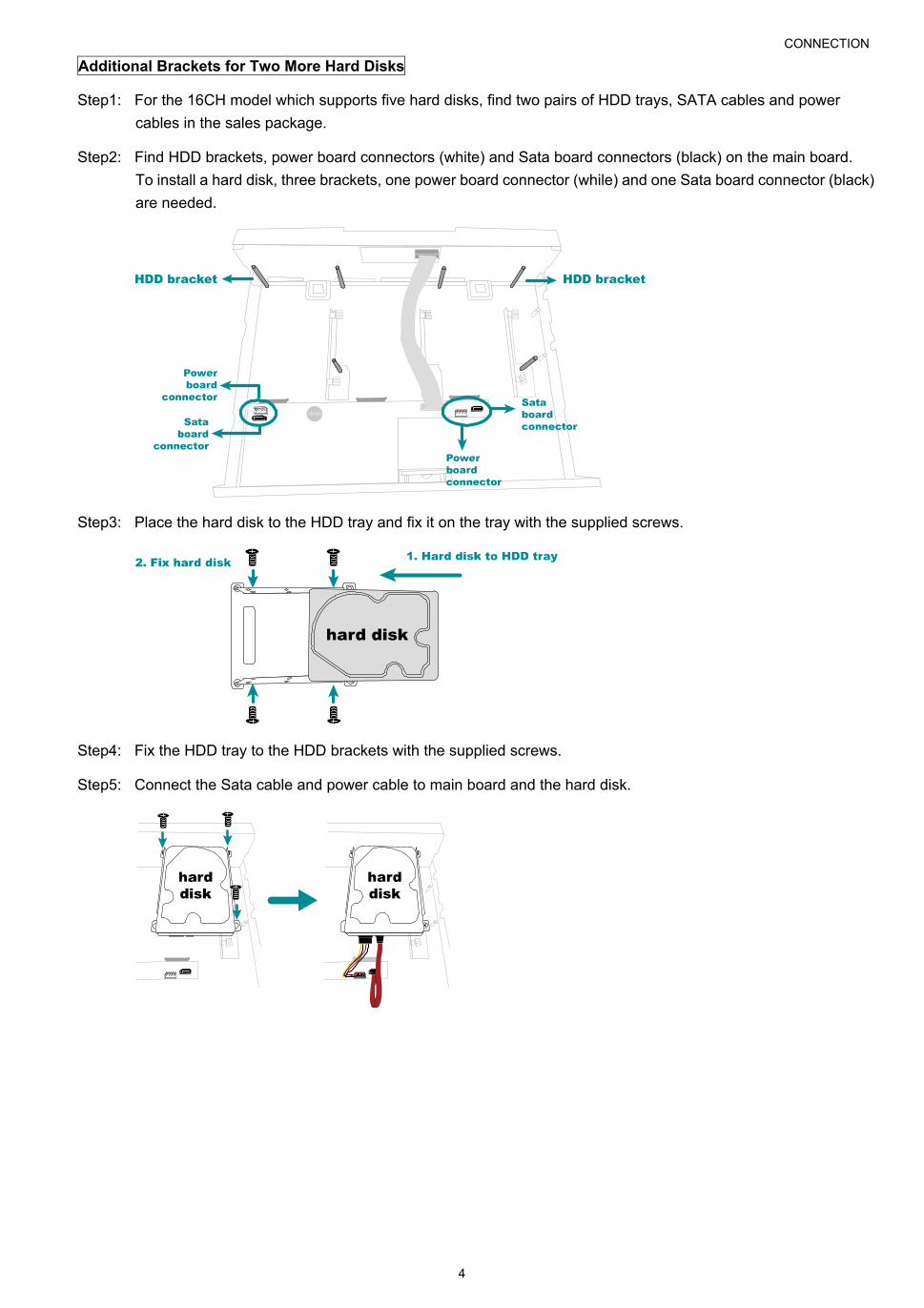
Additional Brackets for Two More Hard Disks
Step1: For the 16CH model which supports five hard disks, find two pairs of HDD trays, SATA cables and power
cables in the sales package.
Step2: Find HDD brackets, power board connectors (white) and Sata board connectors (black) on the main board.
To install a hard disk, three brackets, one power board connector (while) and one Sata board connector (black)
are needed.
Step3: Place the hard disk to the HDD tray and fix it on the tray with the supplied screws.
Step4: Fix the HDD tray to the HDD brackets with the supplied screws.
Step5: Connect the Sata cable and power cable to main board and the hard disk.
CONNECTION
5
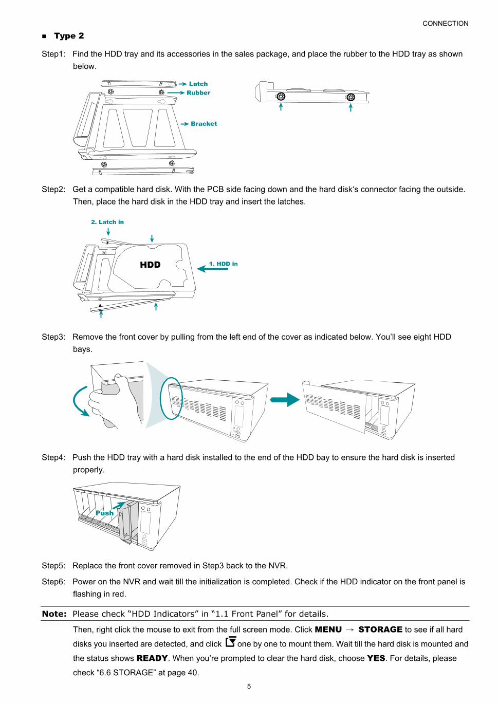
Type 2
Step1: Find the HDD tray and its accessories in the sales package, and place the rubber to the HDD tray as shown
below.
Step2: Get a compatible hard disk. With the PCB side facing down and the hard disk‘s connector facing the outside.
Then, place the hard disk in the HDD tray and insert the latches.
Step3: Remove the front cover by pulling from the left end of the cover as indicated below. You’ll see eight HDD
bays.
Step4: Push the HDD tray with a hard disk installed to the end of the HDD bay to ensure the hard disk is inserted
properly.
Step5: Replace the front cover removed in Step3 back to the NVR.
Step6: Power on the NVR and wait till the initialization is completed. Check if the HDD indicator on the front panel is
flashing in red.
Note: Please check “HDD Indicators” in “1.1 Front Panel” for details.
Then, right click the mouse to exit from the full screen mode. Click MENU → STORAGE to see if all hard
disks you inserted are detected, and click one by one to mount them. Wait till the hard disk is mounted and
the status shows READY. When you’re prompted to clear the hard disk, choose YES. For details, please
check “6.6 STORAGE” at page 40.
CONNECTION
6
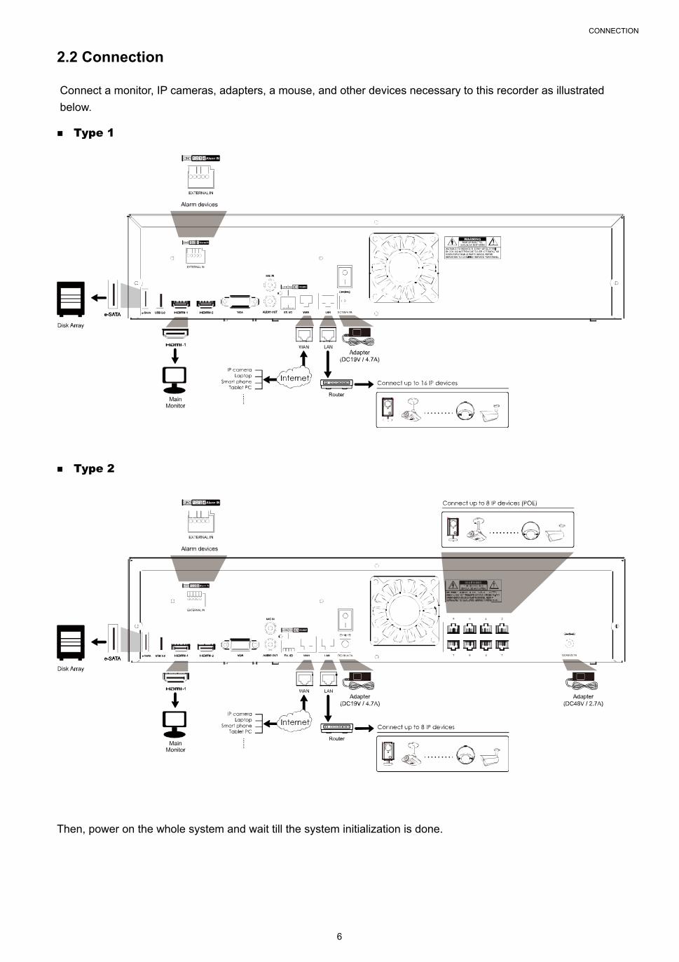
2.2 Connection
Connect a monitor, IP cameras, adapters, a mouse, and other devices necessary to this recorder as illustrated
below.
Type 1
Type 2
Then, power on the whole system and wait till the system initialization is done.
CONNECTION
7
2.3 Camera IP Configurations by LAN
The auto mode is used to simplify the complicated network settings within three minutes. The connection mode
of the LAN port is AUTO by default. This mode is suitable when the LAN port of the device is connected to a
hub / switch.
Note: SETTING Path: MENU NETWORK LAN MODE.
Note: For access this recorder remotely with your mobile device or laptop, you need to connect this recorder to Internet. For details, please get the setup manual from the supplied CD or from www.surveillance-download.com/user/network_setup/network_setup_recorder.pdf.
The device will automatically configure the IP address of a camera connected by LAN if:
The connected IP camera is our brand’s IP camera.
The IP configuration method of the camera is DHCP.
The camera is powered on before the device is powered on.
If the device doesn’t configure the IP address of your camera automatically as described above, your IP
camera might NOT be:
Our brand’s IP camera.
Set to DHCP as its default IP configuration method.
To solve this, reconfigure the IP address of the camera to 10.1.1.xx (xx ranges from 11 ~ 253), which is in the
same network segment as the device.
For other brand’s IP camera, please check its user manual to know how to change the IP address
manually.
For our brand’s IP camera, please check the instructions below:
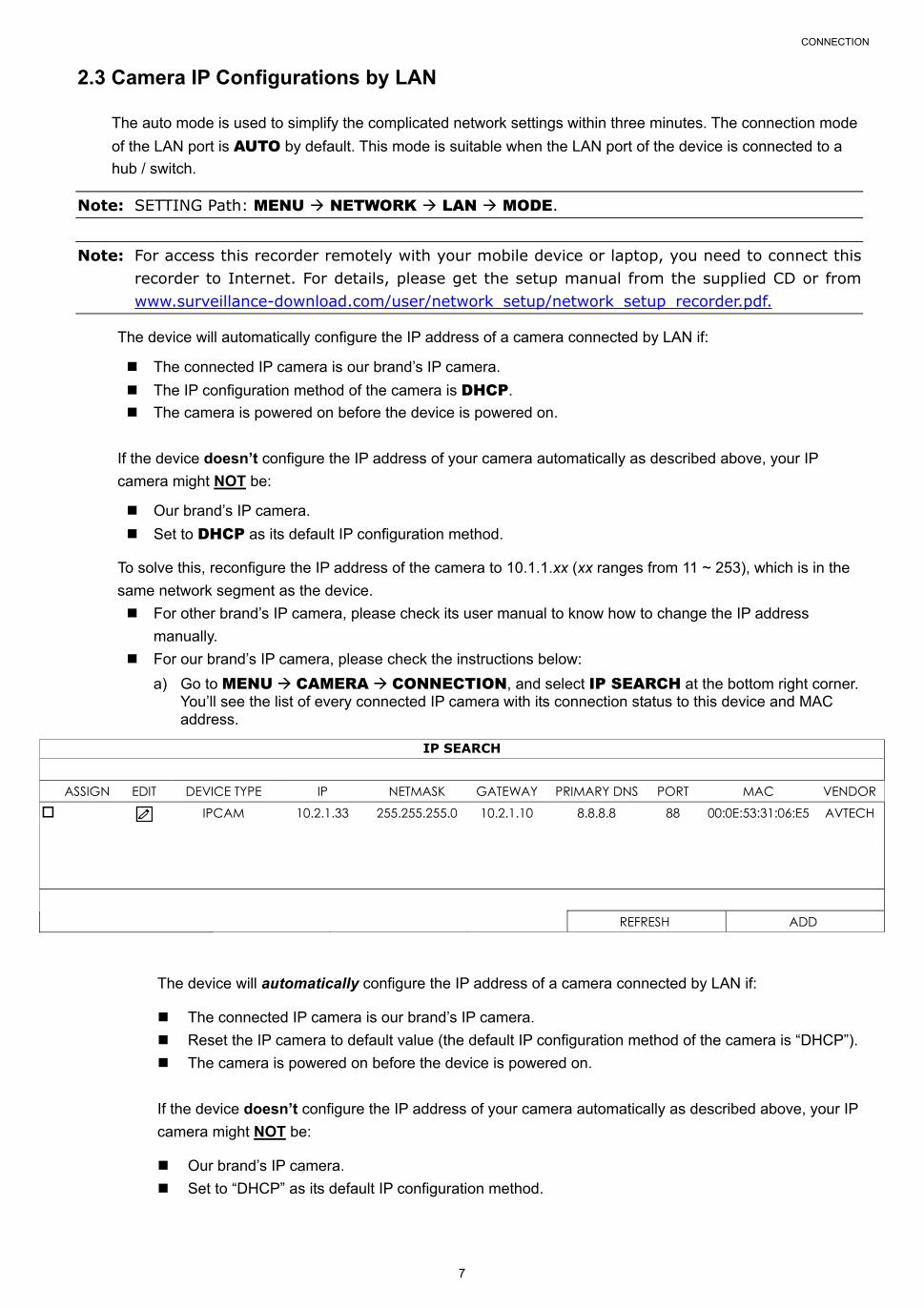
a) Go to MENU CAMERA CONNECTION, and select IP SEARCH at the bottom right corner. You’ll see the list of every connected IP camera with its connection status to this device and MAC address.
IP SEARCH ASSIGN EDIT DEVICE TYPE IP NETMASK GATEWAY PRIMARY DNS PORT MAC VENDOR IPCAM 10.2.1.33 255.255.255.0 10.2.1.10 8.8.8.8 88 00:0E:53:31:06:E5 AVTECH
REFRESH ADD
The device will automatically configure the IP address of a camera connected by LAN if:
The connected IP camera is our brand’s IP camera.
Reset the IP camera to default value (the default IP configuration method of the camera is “DHCP”).
The camera is powered on before the device is powered on.
If the device doesn’t configure the IP address of your camera automatically as described above, your IP
camera might NOT be:
Our brand’s IP camera.
Set to “DHCP” as its default IP configuration method.

CONNECTION
8
b) To solve this, use our brand’s IP camera, and reconfigure its IP address to 10.1.1.xx (xx ranges from 11 ~ 253). Select (EDIT), and change the network type from STATIC to DHCP. Then, Click APPLY to save your changes.
SETUP NETWORK TYPE DHCP IP 10.1.1.14 PORT 88 USER NAME Admin PASSWORD ***** NETMASK 255.255.255.0 GATEWAY 10.1.1.10 PRIMARY DNS 8.8.8.8 CANCEL APPLY
c) Check to assign the camera to a specific channel automatically, and choose ADD.
IP SEARCH ASSIGN EDIT DEVICE TYPE IP NETMASK GATEWAY PRIMARY DNS PORT MAC VENDOR CH1 IPCAM 10.1.1.14 255.255.255.0 10.1.1.10 8.8.8.8 88 00:0E:53:31:06:E5 AVTECH
REFRESH ADD
d) The device will then detect the IP camera and display images soon.
Note: To configure this recorder to access other IP camera connected remotely for live viewing or video backup, you need to connect this recorder to Internet first.

FOR INITIAL USE
9
3. FOR INITIAL USE
For the first time to power on this device, you might be prompted to:
Go through the setup wizard
Clear hard disk
Change default user name and password
3.1 Setup Wizard
The setup wizard is prompted to guide you finishing the most common settings you might need to do.
Note: It’s okay to skip the wizard. You can configure the following settings later in their respective menus.
SETUP WIZARD ENGLISH
WELCOME TO THE SETUP WIZARD.
PLEASE FOLLOW THE WIZARD TO FINISH BASIC CONFIGURATIONS.
SKIP NEXT
Select NEXT to go to the next step.
SETUP WIZARD
PLEASE INPUT THIS MACHINE NAME
SKIP PREV NEXT
Name the device. If you don’t want to name the device, just skip to the next step.
Note: To name the device later, please go to MAINTAIN SYSTEM.
SETUP WIZARD USER NAME office_hd PASSWORD office145 CONFIRM PASSWORD office145
PLEASE INPUT THE ADMINISTRATOR’S USER NAME AND PASSWORD.
SKIP PREV NEXT
Change the default user name and password. If you don’t change the user name and password here, you’re not
able to go to the next step. This step is compulsory.
Note: To change or edit user name and passwords, please go to SYSTEM ACCOUNT USER LIST.
FOR INITIAL USE
10
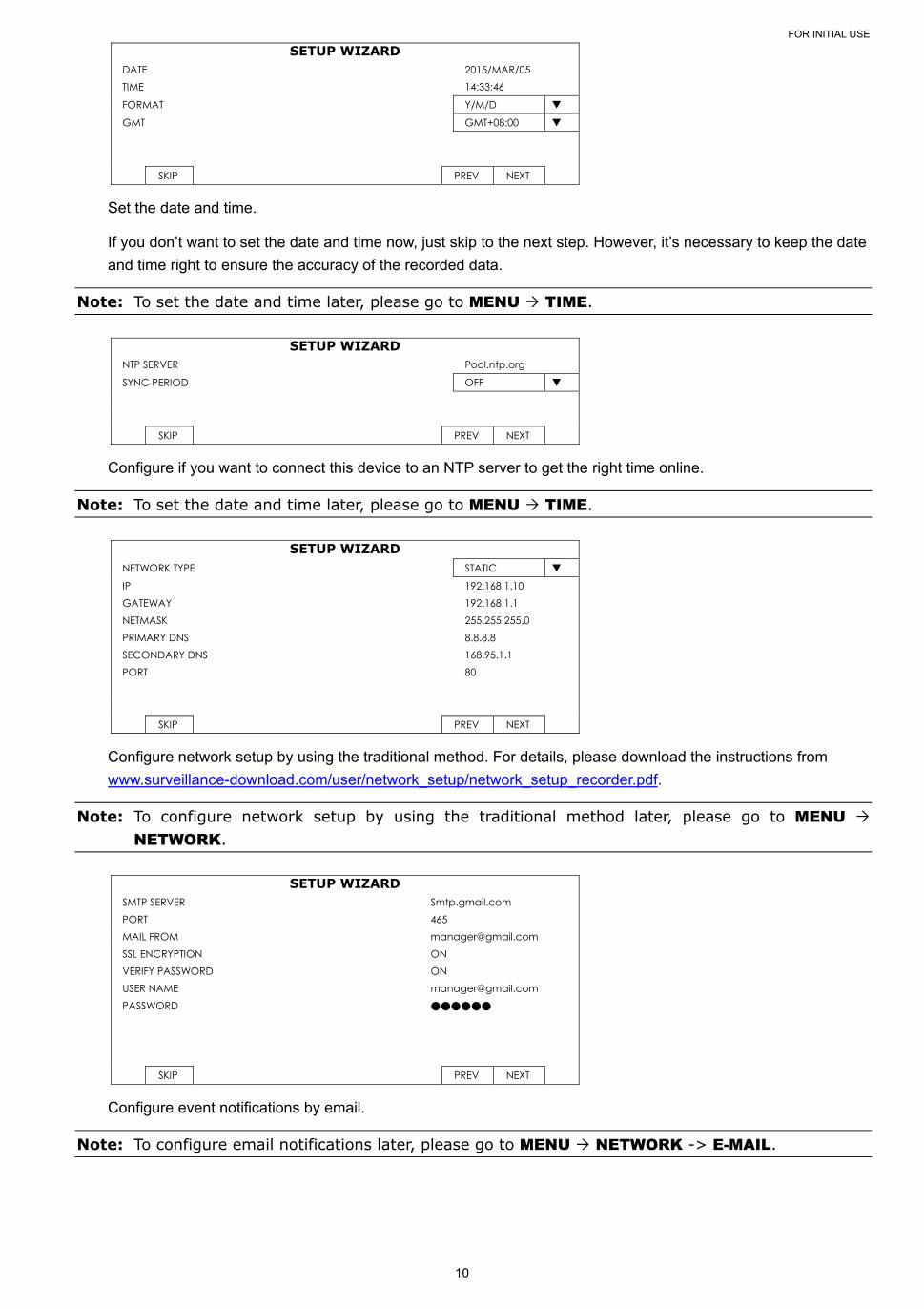
SETUP WIZARD DATE 2015/MAR/05 TIME 14:33:46
FORMAT Y/M/D
GMT GMT+08:00
SKIP PREV NEXT
Set the date and time.
If you don’t want to set the date and time now, just skip to the next step. However, it’s necessary to keep the date
and time right to ensure the accuracy of the recorded data.
Note: To set the date and time later, please go to MENU TIME.
SETUP WIZARD NTP SERVER Pool.ntp.org
SYNC PERIOD OFF
SKIP PREV NEXT
Configure if you want to connect this device to an NTP server to get the right time online.
Note: To set the date and time later, please go to MENU TIME.
SETUP WIZARD NETWORK TYPE STATIC
IP 192.168.1.10 GATEWAY 192.168.1.1 NETMASK 255.255.255.0 PRIMARY DNS 8.8.8.8 SECONDARY DNS 168.95.1.1 PORT 80
SKIP PREV NEXT
Configure network setup by using the traditional method. For details, please download the instructions from
www.surveillance-download.com/user/network_setup/network_setup_recorder.pdf.
Note: To configure network setup by using the traditional method later, please go to MENU NETWORK.
SETUP WIZARD
SMTP SERVER Smtp.gmail.com PORT 465 MAIL FROM [email protected] SSL ENCRYPTION ON VERIFY PASSWORD ON USER NAME [email protected] PASSWORD ●●●●●●
SKIP PREV NEXT
Configure event notifications by email.
Note: To configure email notifications later, please go to MENU NETWORK -> E-MAIL.
FOR INITIAL USE
11
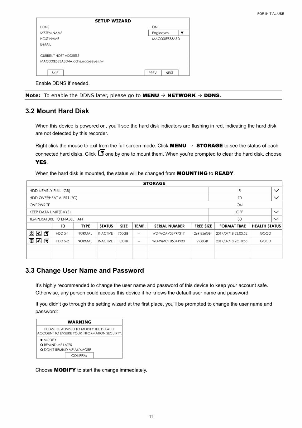
SETUP WIZARD DDNS ON
SYSTEM NAME Eagleeyes
HOST NAME MAC000E533A3D E-MAIL CURRENT HOST ADDRESS MAC000E533A3D4A.ddns.eagleeyes.tw
SKIP PREV NEXT
Enable DDNS if needed.
Note: To enable the DDNS later, please go to MENU NETWORK DDNS.
3.2 Mount Hard Disk
When this device is powered on, you’ll see the hard disk indicators are flashing in red, indicating the hard disk
are not detected by this recorder.
Right click the mouse to exit from the full screen mode. Click MENU → STORAGE to see the status of each
connected hard disks. Click one by one to mount them. When you’re prompted to clear the hard disk, choose
YES.
When the hard disk is mounted, the status will be changed from MOUNTING to READY.
STORAGE HDD NEARLY FULL (GB) 5
HDD OVERHEAT ALERT (°C) 70
OVERWRITE ON
KEEP DATA LIMIT(DAYS) OFF
TEMPERATURE TO ENABLE FAN 30
ID TYPE STATUS SIZE TEMP. SERIAL NUMBER FREE SIZE FORMAT TIME HEALTH STATUS
HDD 5-1 NORMAL INACTIVE 750GB -- WD-WCAV53797317 269.856GB 2017/07/18 23:03:52 GOOD
HDD 5-2 NORMAL INACTIVE 1.00TB -- WD-WMC1U5344933 9.88GB 2017/07/18 23:10:55 GOOD
3.3 Change User Name and Password
It’s highly recommended to change the user name and password of this device to keep your account safe.
Otherwise, any person could access this device if he knows the default user name and password.
If you didn’t go through the setting wizard at the first place, you’ll be prompted to change the user name and
password:
WARNING PLEASE BE ADVISED TO MODIFY THE DEFAULT
ACCOUNT TO ENSURE YOUR INFORMATION SECUIRTY.
MODIFY O REMIND ME LATER O DON’T REMIND ME ANYMORE
CONFIRM
Choose MODIFY to start the change immediately.

FOR INITIAL USE
12
To change later, go to MENU ACCOUNT USER LIST, and choose to change the default user
name and password of SUPERVISOR.
USER LIST USER LIST
GROUP EDIT USER NAME GROUP admin SUPERVISOR
USER INTERFACE
13
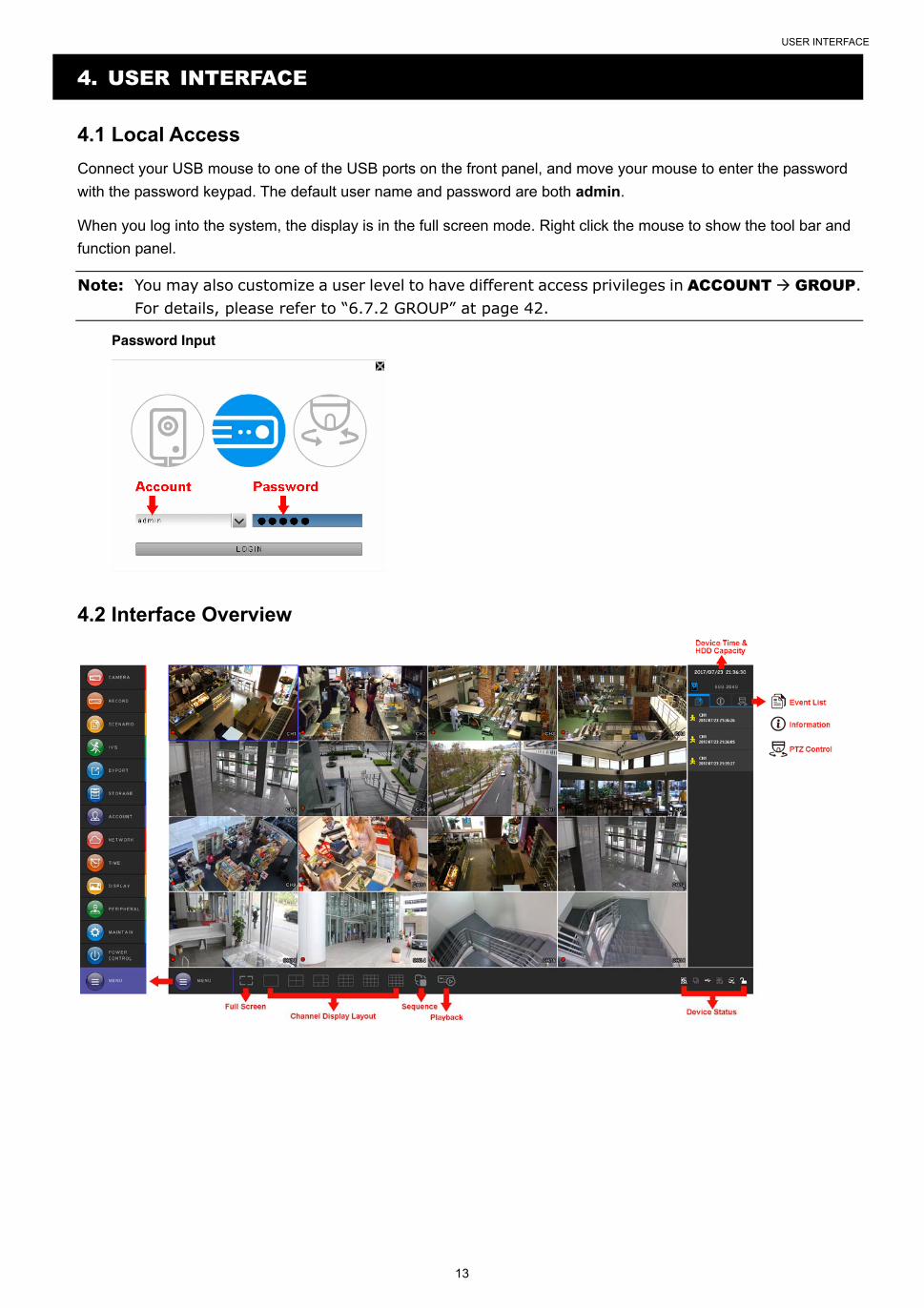
4. USER INTERFACE
4.1 Local Access
Connect your USB mouse to one of the USB ports on the front panel, and move your mouse to enter the password
with the password keypad. The default user name and password are both admin.
When you log into the system, the display is in the full screen mode. Right click the mouse to show the tool bar and
function panel.
Note: You may also customize a user level to have different access privileges in ACCOUNT GROUP. For details, please refer to “6.7.2 GROUP” at page 42.
Password Input
4.2 Interface Overview

USER INTERFACE
14
4.3 Status & Operation
4.3.1 Device Status
Note: The functions shown may vary based on the model or the access user level you use.
Key lock Key unlock
Channel lock Channel unlock
USB flash drive / device connected No USB device connected
Timer record on Timer record off
Overwrite on Overwrite off
Sequence mode on Sequence mode off
PTZ mode on PTZ mode off
USB backup in progress USB flash drive full
USB backup failed CPU loading
Network Status:
(WAN) Internet connected (WAN) Internet disconnected
(WAN) Local connection
(LAN) DHCP / Static IP mode (LAN) Camera disconnected
4.3.2 Channel Status
Note: The functions shown may vary based on the model or the access user level you use.
Camera disconnected Original size Fit to screen Digital zoom
Audio on Audio off Alarm out Alarm out disabled
Recording Alarm event Motion event PIR event
Add a camera by auto search
Add a camera manually IP camera setup
FREQUENTLY-USED FUNCTIONS
15
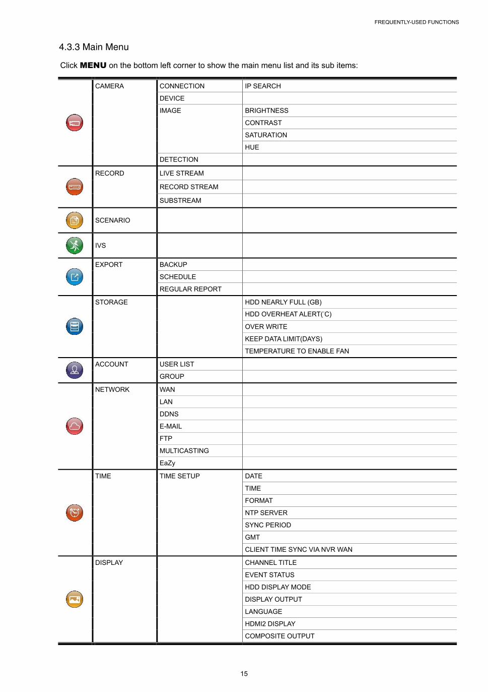
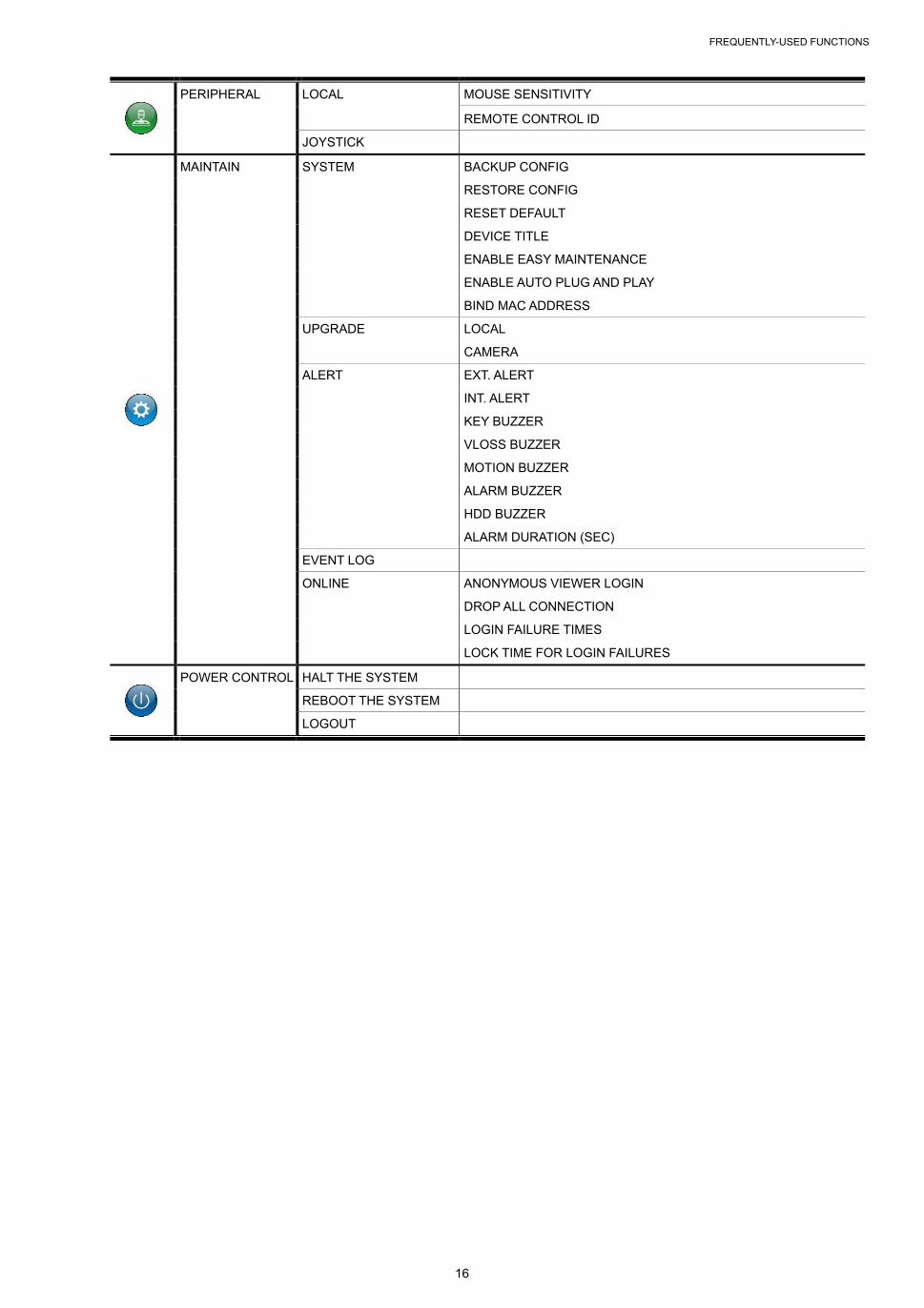
4.3.3 Main Menu
Click MENU on the bottom left corner to show the main menu list and its sub items:
CAMERA CONNECTION IP SEARCH
DEVICE
IMAGE BRIGHTNESS
CONTRAST
SATURATION
HUE
DETECTION
RECORD LIVE STREAM
RECORD STREAM
SUBSTREAM
SCENARIO
IVS
EXPORT BACKUP
SCHEDULE
REGULAR REPORT
STORAGE HDD NEARLY FULL (GB)
HDD OVERHEAT ALERT(°C)
OVER WRITE
KEEP DATA LIMIT(DAYS)
TEMPERATURE TO ENABLE FAN
ACCOUNT USER LIST
GROUP
NETWORK WAN
LAN
DDNS
FTP
MULTICASTING
EaZy
TIME TIME SETUP DATE
TIME
FORMAT
NTP SERVER
SYNC PERIOD
GMT
CLIENT TIME SYNC VIA NVR WAN
DISPLAY CHANNEL TITLE
EVENT STATUS
HDD DISPLAY MODE
DISPLAY OUTPUT
LANGUAGE
HDMI2 DISPLAY
COMPOSITE OUTPUT
FREQUENTLY-USED FUNCTIONS
16
PERIPHERAL LOCAL MOUSE SENSITIVITY
REMOTE CONTROL ID
JOYSTICK
MAINTAIN SYSTEM BACKUP CONFIG
RESTORE CONFIG
RESET DEFAULT
DEVICE TITLE
ENABLE EASY MAINTENANCE
ENABLE AUTO PLUG AND PLAY
BIND MAC ADDRESS
UPGRADE LOCAL
CAMERA
ALERT EXT. ALERT
INT. ALERT
KEY BUZZER
VLOSS BUZZER
MOTION BUZZER
ALARM BUZZER
HDD BUZZER
ALARM DURATION (SEC)
EVENT LOG
ONLINE ANONYMOUS VIEWER LOGIN
DROP ALL CONNECTION
LOGIN FAILURE TIMES
LOCK TIME FOR LOGIN FAILURES
POWER CONTROL HALT THE SYSTEM
REBOOT THE SYSTEM
LOGOUT
FREQUENTLY-USED FUNCTIONS
17
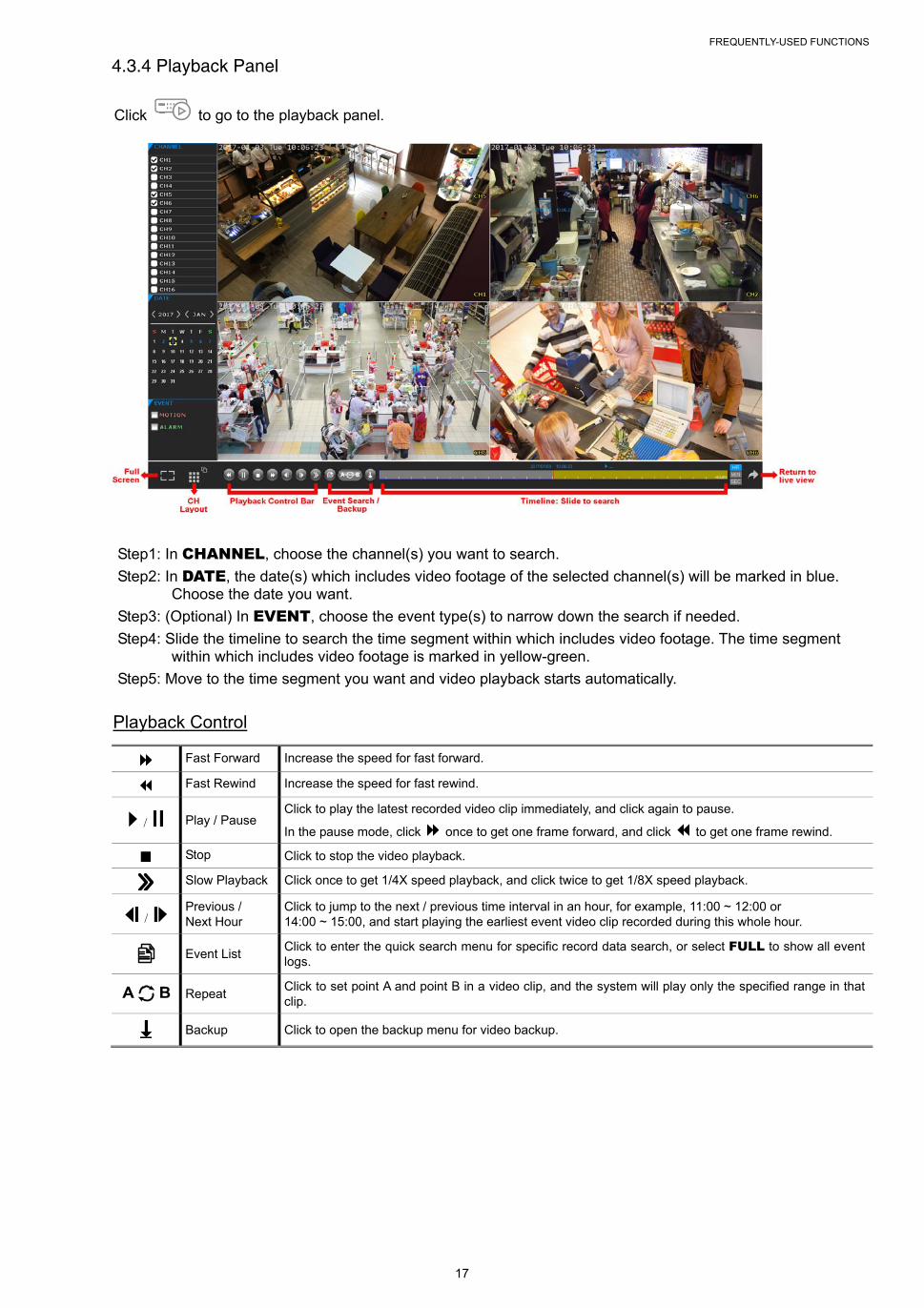
4.3.4 Playback Panel
Click to go to the playback panel.
Step1: In CHANNEL, choose the channel(s) you want to search.
Step2: In DATE, the date(s) which includes video footage of the selected channel(s) will be marked in blue. Choose the date you want.
Step3: (Optional) In EVENT, choose the event type(s) to narrow down the search if needed.
Step4: Slide the timeline to search the time segment within which includes video footage. The time segment within which includes video footage is marked in yellow-green.
Step5: Move to the time segment you want and video playback starts automatically.
Playback Control
Fast Forward Increase the speed for fast forward.
Fast Rewind Increase the speed for fast rewind.
/ Play / Pause Click to play the latest recorded video clip immediately, and click again to pause.
In the pause mode, click once to get one frame forward, and click to get one frame rewind.
Stop Click to stop the video playback.
Slow Playback Click once to get 1/4X speed playback, and click twice to get 1/8X speed playback.
/ Previous / Next Hour
Click to jump to the next / previous time interval in an hour, for example, 11:00 ~ 12:00 or 14:00 ~ 15:00, and start playing the earliest event video clip recorded during this whole hour.
Event List Click to enter the quick search menu for specific record data search, or select FULL to show all event logs.
Repeat Click to set point A and point B in a video clip, and the system will play only the specified range in that clip.
Backup Click to open the backup menu for video backup.
FREQUENTLY-USED FUNCTIONS
18
5. FREQUENTLY-USED FUNCTIONS
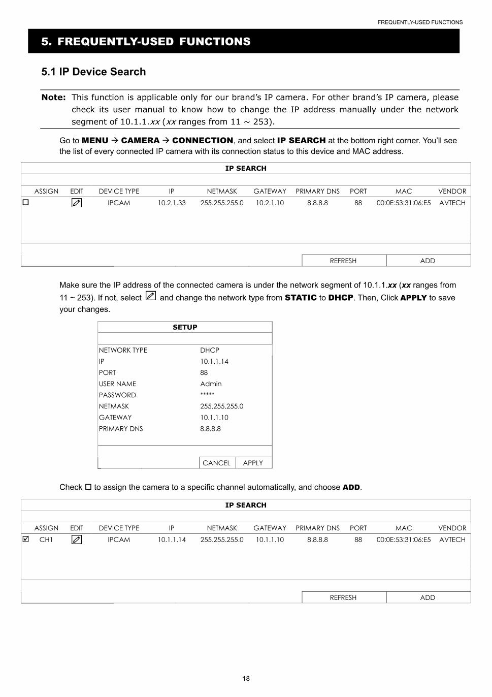
5.1 IP Device Search
Note: This function is applicable only for our brand’s IP camera. For other brand’s IP camera, please check its user manual to know how to change the IP address manually under the network segment of 10.1.1.xx (xx ranges from 11 ~ 253).
Go to MENU CAMERA CONNECTION, and select IP SEARCH at the bottom right corner. You’ll see the list of every connected IP camera with its connection status to this device and MAC address.
IP SEARCH ASSIGN EDIT DEVICE TYPE IP NETMASK GATEWAY PRIMARY DNS PORT MAC VENDOR IPCAM 10.2.1.33 255.255.255.0 10.2.1.10 8.8.8.8 88 00:0E:53:31:06:E5 AVTECH
REFRESH ADD
Make sure the IP address of the connected camera is under the network segment of 10.1.1.xx (xx ranges from
11 ~ 253). If not, select and change the network type from STATIC to DHCP. Then, Click APPLY to save
your changes.
SETUP NETWORK TYPE DHCP IP 10.1.1.14 PORT 88 USER NAME Admin PASSWORD ***** NETMASK 255.255.255.0 GATEWAY 10.1.1.10 PRIMARY DNS 8.8.8.8 CANCEL APPLY
Check to assign the camera to a specific channel automatically, and choose ADD.
IP SEARCH ASSIGN EDIT DEVICE TYPE IP NETMASK GATEWAY PRIMARY DNS PORT MAC VENDOR CH1 IPCAM 10.1.1.14 255.255.255.0 10.1.1.10 8.8.8.8 88 00:0E:53:31:06:E5 AVTECH
REFRESH ADD

FREQUENTLY-USED FUNCTIONS
19
5.2 User Account Creation
To create different user account for different access privilege, go to MENU ACCOUNT USER LIST,
and choose to create a new account.
USER LIST USER LIST
GROUP EDIT USER NAME GROUP admin SUPERVISOR
Four user levels are pre-defined in the system for you to quickly choose: SUPERVISOR, POWER USER, USER
& GUEST.
Note: You can also customize a user level based on your needs by going to MENU ACCOUNT GROUP. For details, please go to “6.7.2 GROUP” at page 42.
Function User Level
SUPERVISOR POWER USER USER GUEST
GENERAL
BACKUP
PTZ CONTROL
POWER CONTROL
REVIEW LOG
CONFIG SETUP
CLEAR LOG
ACCOUNT SETUP
CLEAR HDD
PUSH VIDEO
PUSH STATUS
ALARM OUT
LOCAL
LIVE VIDEO
LIVE AUDIO
PLAYBACK VIDEO
PLAYBACK AUDIO
NETWORK
LIVE VIDEO
LIVE AUDIO
PLAYBACK VIDEO
PLAYBACK AUDIO

FREQUENTLY-USED FUNCTIONS
20
5.3 System Logout
When different user accounts are created for system management, make sure you log out after your access in case other people access the system with your account.
Choose MENU → POWER CONTROL, and choose to log out the system.
Note: The default user name and password are both admin, which is the highest user level.
5.4 PTZ Control
Enter Click to confirm your selection / enter the menu.
/ / / Up / Down / Left / Right Click the arrow keys ( / / / ) to more the camera lens up / down / left /right.
Camera Control
/ Iris + / Iris - This two buttons are designed for the PTZ camera which uses Pelco-D to control. To know the actions after clicking Iris + and Iris -, please refer to the camera’s user manual.
/ Focus near / far Click to adjust the focus of the image.
FREQUENTLY-USED FUNCTIONS
21
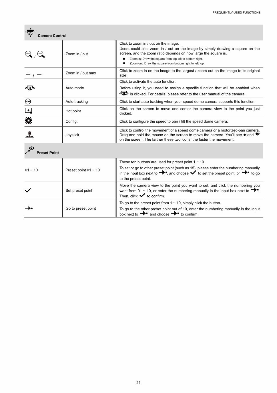
Camera Control
/ Zoom in / out
Click to zoom in / out on the image. Users could also zoom in / out on the image by simply drawing a square on the screen, and the zoom ratio depends on how large the square is. Zoom in: Draw the square from top left to bottom right.
Zoom out: Draw the square from bottom right to left top.
+ / - Zoom in / out max Click to zoom in on the image to the largest / zoom out on the image to its original size.
Auto mode
Click to activate the auto function.
Before using it, you need to assign a specific function that will be enabled when
is clicked. For details, please refer to the user manual of the camera.
Auto tracking Click to start auto tracking when your speed dome camera supports this function.
Hot point Click on the screen to move and center the camera view to the point you just clicked.
Config. Click to configure the speed to pan / tilt the speed dome camera.
Joystick Click to control the movement of a speed dome camera or a motorized-pan camera. Drag and hold the mouse on the screen to move the camera. You’ll see and on the screen. The farther these two icons, the faster the movement.
Preset Point
01 ~ 10 Preset point 01 ~ 10
These ten buttons are used for preset point 1 ~ 10.
To set or go to other preset point (such as 15), please enter the numbering manually
in the input box next to , and choose to set the preset point, or to go
to the preset point.
Set preset point Move the camera view to the point you want to set, and click the numbering you
want from 01 ~ 10, or enter the numbering manually in the input box next to .
Then, click to confirm.
Go to preset point
To go to the preset point from 1 ~ 10, simply click the button.
To go to the other preset point out of 10, enter the numbering manually in the input
box next to , and choose to confirm.
REMOTE OPERATION
22
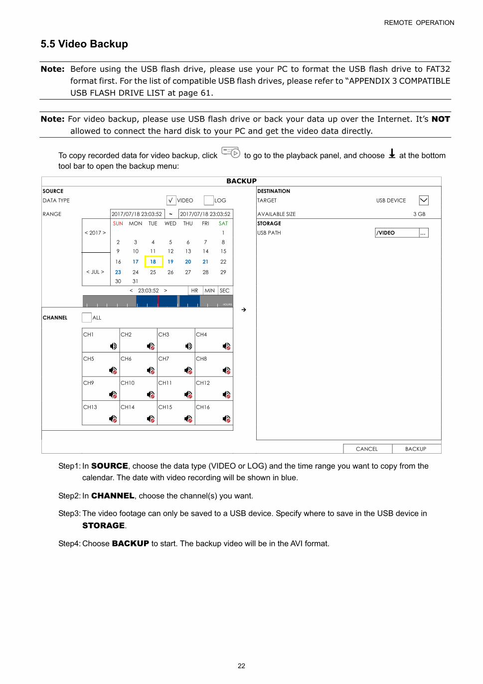
5.5 Video Backup
Note: Before using the USB flash drive, please use your PC to format the USB flash drive to FAT32 format first. For the list of compatible USB flash drives, please refer to “APPENDIX 3 COMPATIBLE USB FLASH DRIVE LIST at page 61.
Note: For video backup, please use USB flash drive or back your data up over the Internet. It’s NOT allowed to connect the hard disk to your PC and get the video data directly.
To copy recorded data for video backup, click to go to the playback panel, and choose at the bottom tool bar to open the backup menu:
BACKUP SOURCE DESTINATION DATA TYPE √ VIDEO LOG TARGET USB DEVICE RANGE 2017/07/18 23:03:52 ~ 2017/07/18 23:03:52 AVAILABLE SIZE 3 GB
< 2017 >
< JUL >
SUN MON TUE WED THU FRI SAT STORAGE
1 USB PATH /VIDEO …
2 3 4 5 6 7 8 9 10 11 12 13 14 15
16 17 18 19 20 21 22
23 24 25 26 27 28 29 30 31
< 23:03:52 > HR MIN SEC
HOURS
CHANNEL ALL CH1
CH2
CH3
CH4
CH5
CH6
CH7
CH8
CH9
CH10
CH11
CH12
CH13
CH14
CH15
CH16
CANCEL BACKUP
Step1: In SOURCE, choose the data type (VIDEO or LOG) and the time range you want to copy from the
calendar. The date with video recording will be shown in blue.
Step2: In CHANNEL, choose the channel(s) you want.
Step3: The video footage can only be saved to a USB device. Specify where to save in the USB device in
STORAGE.
Step4: Choose BACKUP to start. The backup video will be in the AVI format.

MAIN MENU
23
6. MAIN MENU
6.1 CAMERA
6.1.1 CONNECTION
To know how to add our brand’s IP cameras automatically, please refer to “2.3 Camera IP Configurations by
LAN” at 7.
To manually add a camera connected locally or remotely, click to enter the setup page.
Note: Before connecting other brand’s IP camera, make sure its IP address is set to 10.1.1.xx (xx ranges from 11 ~ 253). To know how to change the IP address of the camera, please refer to its user manual.
CONNECTION
EDIT ENABLE CHANNEL TITLE URI PORT DEVICE TYPE VENDOR MODEL STREAM PROTOCOL METHOD PATH1 PATH2
CH1 10.1.1.11 88 IPCAM RTP-Unicast HTTP
IP SEARCH
In the setup page, enter the access information of the camera, and click APPLY to confirm.
VENDOR ONVIF MODEL STREAM PROTOCOL RTP-Unicast METHOD TCP URI 10.1.1.22 PORT 82 PATH1 PATH2 USER NAME test1234 PASSWORD ●●●●●
CANCEL APPLY
MAIN MENU
24
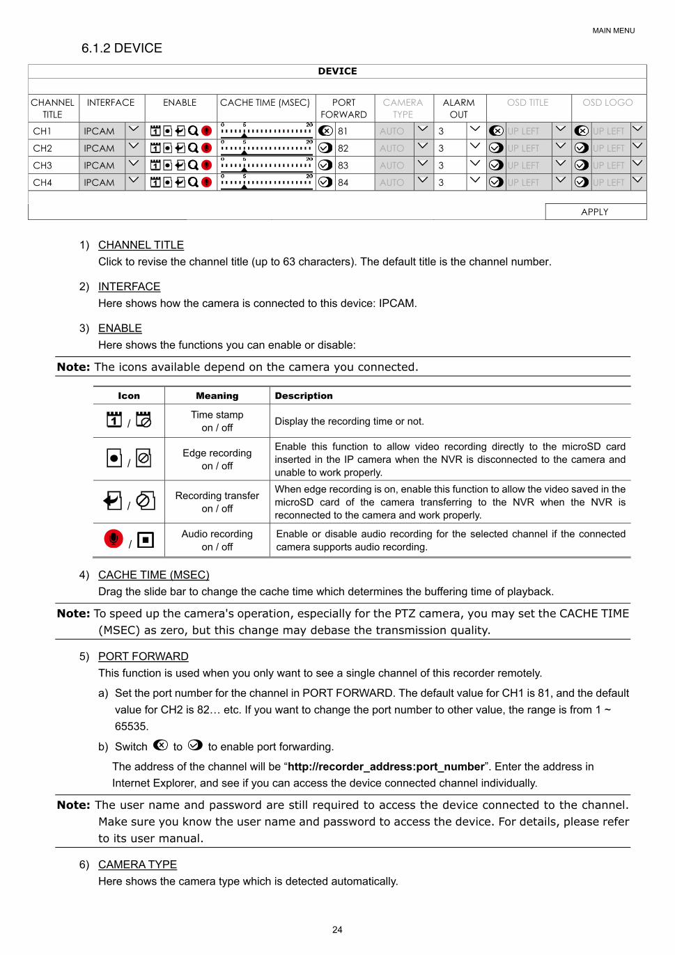
6.1.2 DEVICE
DEVICE CHANNEL
TITLE INTERFACE ENABLE CACHE TIME (MSEC) PORT
FORWARD CAMERA
TYPE ALARM
OUT OSD TITLE OSD LOGO
CH1 IPCAM 81 AUTO 3 UP LEFT UP LEFT
CH2 IPCAM 82 AUTO 3 UP LEFT UP LEFT
CH3 IPCAM 83 AUTO 3 UP LEFT UP LEFT
CH4 IPCAM 84 AUTO 3 UP LEFT UP LEFT
APPLY
1) CHANNEL TITLE
Click to revise the channel title (up to 63 characters). The default title is the channel number.
2) INTERFACE
Here shows how the camera is connected to this device: IPCAM.
3) ENABLE
Here shows the functions you can enable or disable:
Note: The icons available depend on the camera you connected.
Icon Meaning Description
/ Time stamp
on / off Display the recording time or not.
/ Edge recording
on / off
Enable this function to allow video recording directly to the microSD card inserted in the IP camera when the NVR is disconnected to the camera and unable to work properly.
/ Recording transfer
on / off
When edge recording is on, enable this function to allow the video saved in the microSD card of the camera transferring to the NVR when the NVR is reconnected to the camera and work properly.
/ Audio recording
on / off Enable or disable audio recording for the selected channel if the connected camera supports audio recording.
4) CACHE TIME (MSEC)
Drag the slide bar to change the cache time which determines the buffering time of playback.
Note: To speed up the camera's operation, especially for the PTZ camera, you may set the CACHE TIME (MSEC) as zero, but this change may debase the transmission quality.
5) PORT FORWARD
This function is used when you only want to see a single channel of this recorder remotely.
a) Set the port number for the channel in PORT FORWARD. The default value for CH1 is 81, and the default
value for CH2 is 82… etc. If you want to change the port number to other value, the range is from 1 ~
65535.
b) Switch to to enable port forwarding.
The address of the channel will be “http://recorder_address:port_number”. Enter the address in
Internet Explorer, and see if you can access the device connected channel individually.
Note: The user name and password are still required to access the device connected to the channel. Make sure you know the user name and password to access the device. For details, please refer to its user manual.
6) CAMERA TYPE
Here shows the camera type which is detected automatically.
MAIN MENU
25
7) ALARM OUT (Depending on the camera you connected)
This function is used to set how long the device should work in seconds when the is clicked on the camera channel.
Note: An alarm-out device (such as a buzzer) should be connected to the IP camera first for this function to take effects.
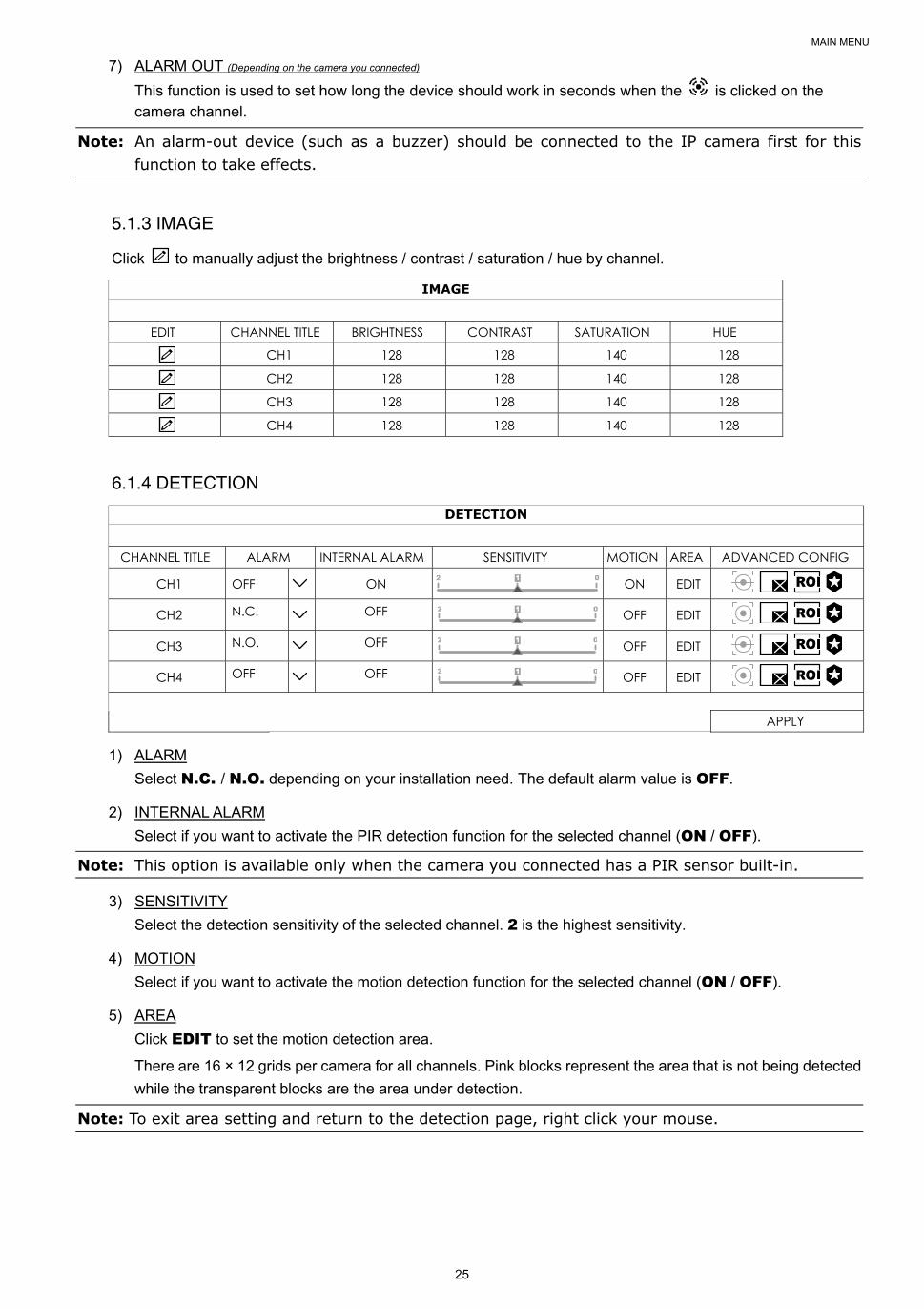
5.1.3 IMAGE
Click to manually adjust the brightness / contrast / saturation / hue by channel.
IMAGE
EDIT CHANNEL TITLE BRIGHTNESS CONTRAST SATURATION HUE
CH1 128 128 140 128
CH2 128 128 140 128
CH3 128 128 140 128
CH4 128 128 140 128
6.1.4 DETECTION
DETECTION
CHANNEL TITLE ALARM INTERNAL ALARM SENSITIVITY MOTION AREA ADVANCED CONFIG
CH1 OFF ON ON EDIT
CH2 N.C. OFF OFF EDIT
CH3 N.O. OFF OFF EDIT
CH4 OFF OFF OFF EDIT
APPLY
1) ALARM
Select N.C. / N.O. depending on your installation need. The default alarm value is OFF.
2) INTERNAL ALARM
Select if you want to activate the PIR detection function for the selected channel (ON / OFF).
Note: This option is available only when the camera you connected has a PIR sensor built-in.
3) SENSITIVITY
Select the detection sensitivity of the selected channel. 2 is the highest sensitivity.
4) MOTION
Select if you want to activate the motion detection function for the selected channel (ON / OFF).
5) AREA
Click EDIT to set the motion detection area.
There are 16 × 12 grids per camera for all channels. Pink blocks represent the area that is not being detected
while the transparent blocks are the area under detection.
Note: To exit area setting and return to the detection page, right click your mouse.
MAIN MENU
26
6) ADVANCED CONFIG
The advanced settings are available only when the connected camera supports.
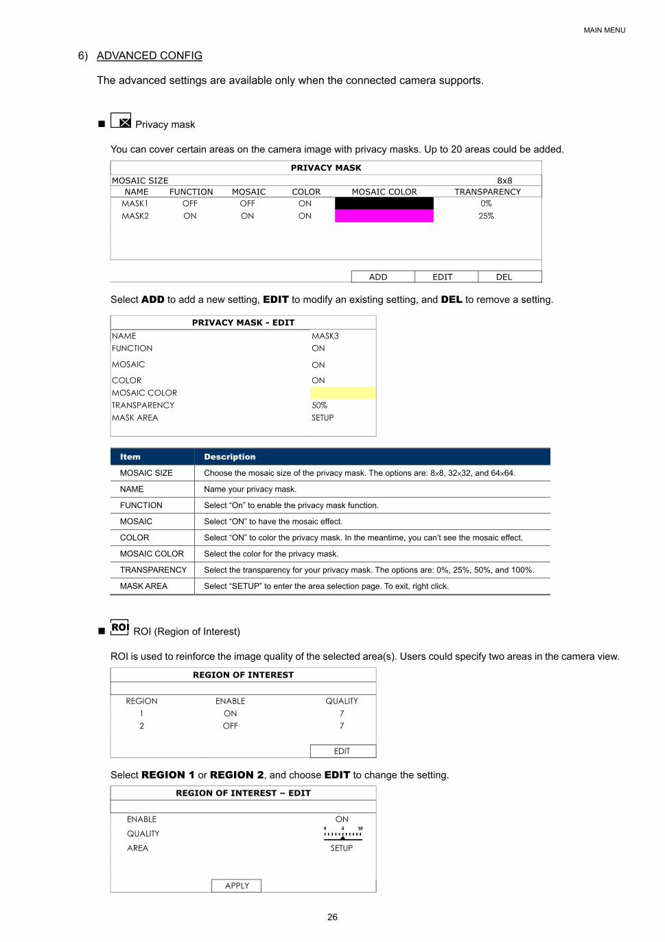
Privacy mask
You can cover certain areas on the camera image with privacy masks. Up to 20 areas could be added.
PRIVACY MASK MOSAIC SIZE 8x8
NAME FUNCTION MOSAIC COLOR MOSAIC COLOR TRANSPARENCY MASK1 OFF OFF ON 0% MASK2 ON ON ON 25%
ADD EDIT DEL
Select ADD to add a new setting, EDIT to modify an existing setting, and DEL to remove a setting.
PRIVACY MASK - EDIT NAME MASK3 FUNCTION ON
MOSAIC ON
COLOR ON MOSAIC COLOR TRANSPARENCY 50% MASK AREA SETUP
Item Description
MOSAIC SIZE Choose the mosaic size of the privacy mask. The options are: 8×8, 32×32, and 64×64.
NAME Name your privacy mask.
FUNCTION Select “On” to enable the privacy mask function.
MOSAIC Select “ON” to have the mosaic effect.
COLOR Select “ON” to color the privacy mask. In the meantime, you can’t see the mosaic effect.
MOSAIC COLOR Select the color for the privacy mask.
TRANSPARENCY Select the transparency for your privacy mask. The options are: 0%, 25%, 50%, and 100%.
MASK AREA Select “SETUP” to enter the area selection page. To exit, right click.
ROI (Region of Interest)
ROI is used to reinforce the image quality of the selected area(s). Users could specify two areas in the camera view.
REGION OF INTEREST
REGION ENABLE QUALITY 1 ON 7 2 OFF 7
EDIT
Select REGION 1 or REGION 2, and choose EDIT to change the setting.
REGION OF INTEREST – EDIT
ENABLE ON
QUALITY
AREA SETUP
APPLY

MAIN MENU
27
Camera Guard
This function is used to lock the camera to a fixed point and no pan action could be made until the lock mode is
disabled. Before using this function, make sure:
1. You’ve configured at least one preset point and one preset group for the connected camera. To know how to configure preset points and preset group, please refer to “” at page .
2. You have an iOS or android mobile device with our free app, EagleEyes, installed.
3. Your recorder is connected to Internet, and registered in the address book of EagleEyes.
CAMERA GUARD – CH1 GUARD LOCK ON TIMEOUT (SECS) 30
PRESET GROUP 1
PRESET NUMBER 1
APPLY
Item Description
GUARD LOCK Enable (ON) or disable (OFF) this function.
TIMEOUT (SECS) Configure the timeout in seconds (30 / 60 / 90 / 120) after which the camera will be fixed to the current point and any attempt to pan the camera to another point will be failed.
PRESET GROUP Choose the group where the point you’d like to use is configured, and go to PRESET NUMBER to choose the preset point number.
PRESET NUMBER Choose the preset point number you’d like to use when GUARD LOCK is enabled.
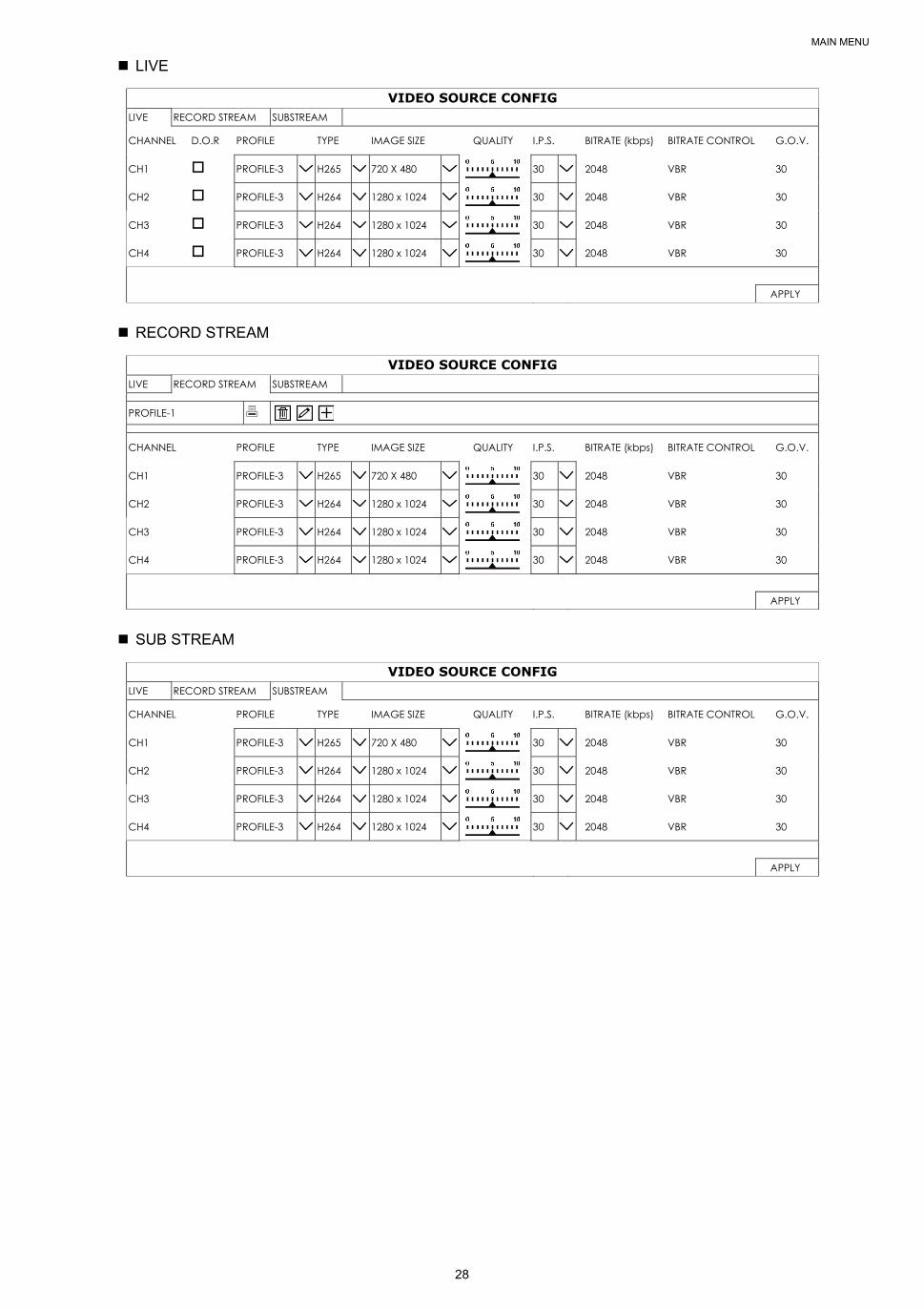
6.2 RECORD
Set the image size, video quality and other related parameters individually for live display, record streaming and
sub streaming.
Note: The settings shown below depend on the setting tab you selected in this setting page.
a) D.O.R (Depend on record): When this option is checked, the video size, quality and other related
parameters will follow the configurations in RECORD STREAM.
b) PROFILE: Select the video profile pre-defined in your IP cameras. You can directly use the profile setting,
or modify the setting on this page.
c) TYPE: Select the compression format for each channel.
Note: The options selectable for TYPE depend on the camera you’re intended to connect.
d) IMAGE SIZE: Select the image size for each channel.
Note: The options selectable for IMAGE SIZE depend on the camera you’re intended to connect.
e) QUALITY: Select the video quality for each channel. The higher the value, the better the image quality.
f) I.P.S.: Image per Second, the higher the value, the more fluent the video.
Note: The options selectable for “I.P.S.” depends on the camera you’re intended to connect.
g) BITRATE (kbps): Select how much data to process per unit of time for each channel. The higher the
value, the better the video quality.
h) BITRATE CONTROL: Configure the upper bit rate limit for the selected channel if necessary.
VBR - When the bit rate of the camera exceeds the value you set, the video fluency may be affected;
CBR - When the bit rate of the camera exceeds the value you set, the image quality may be affected.
i) G.O.V.: “Group of VOPs” is used to configure the length of G.O.V. The greater of the value, the less the
bandwidth for transmission, and the poorer the image quality.
MAIN MENU
28
LIVE
VIDEO SOURCE CONFIG LIVE RECORD STREAM SUBSTREAM
CHANNEL D.O.R PROFILE TYPE IMAGE SIZE QUALITY I.P.S. BITRATE (kbps) BITRATE CONTROL G.O.V.
CH1 PROFILE-3 H265 720 X 480 30 2048 VBR 30
CH2 PROFILE-3 H264 1280 x 1024 30 2048 VBR 30
CH3 PROFILE-3 H264 1280 x 1024 30 2048 VBR 30
CH4 PROFILE-3 H264 1280 x 1024 30 2048 VBR 30
APPLY
RECORD STREAM
VIDEO SOURCE CONFIG LIVE RECORD STREAM SUBSTREAM
PROFILE-1
CHANNEL PROFILE TYPE IMAGE SIZE QUALITY I.P.S. BITRATE (kbps) BITRATE CONTROL G.O.V.
CH1 PROFILE-3 H265 720 X 480 30 2048 VBR 30
CH2 PROFILE-3 H264 1280 x 1024 30 2048 VBR 30
CH3 PROFILE-3 H264 1280 x 1024 30 2048 VBR 30
CH4 PROFILE-3 H264 1280 x 1024 30 2048 VBR 30
APPLY
SUB STREAM
VIDEO SOURCE CONFIG LIVE RECORD STREAM SUBSTREAM
CHANNEL PROFILE TYPE IMAGE SIZE QUALITY I.P.S. BITRATE (kbps) BITRATE CONTROL G.O.V.
CH1 PROFILE-3 H265 720 X 480 30 2048 VBR 30
CH2 PROFILE-3 H264 1280 x 1024 30 2048 VBR 30
CH3 PROFILE-3 H264 1280 x 1024 30 2048 VBR 30
CH4 PROFILE-3 H264 1280 x 1024 30 2048 VBR 30
APPLY
MAIN MENU
29
6.3 SCENARIO
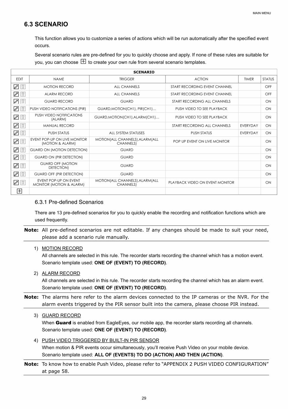
This function allows you to customize a series of actions which will be run automatically after the specified event
occurs.
Several scenario rules are pre-defined for you to quickly choose and apply. If none of these rules are suitable for
you, you can choose to create your own rule from several scenario templates.
SCENARIO
EDIT NAME TRIGGER ACTION TIMER STATUS
MOTION RECORD ALL CHANNELS START RECORDING EVENT CHANNEL OFF
ALARM RECORD ALL CHANNELS START RECORDING EVENT CHANNEL OFF
GUARD RECORD GUARD START RECORDING ALL CHANNELS ON
PUSH VIDEO NOTIFICATIONS (PIR) GUARD,MOTION(CH1), PIR(CH1)… PUSH VIDEO TO SEE PLAYBACK ON
PUSH VIDEO NOTIFICATIONS
(ALARM) GUARD,MOTION(CH1),ALARM(CH1)… PUSH VIDEO TO SEE PLAYBACK ON
MANUAL RECORD START RECORDING ALL CHANNELS EVERYDAY ON
PUSH STATUS ALL SYSTEM STATUSES PUSH STATUS EVERYDAY ON
EVENT POP-UP ON LIVE MONITOR
(MOTION & ALARM) MOTION(ALL CHANNELS),ALARM(ALL
CHANNELS) POP UP EVENT ON LIVE MONITOR ON
GUARD ON (MOTION DETECTION) GUARD ON
GUARD ON (PIR DETECTION) GUARD ON
GUARD OFF (MOTION
DETECTION) GUARD ON
GUARD OFF (PIR DETECTION) GUARD ON
EVENT POP-UP ON EVENT
MONITOR (MOTION & ALARM) MOTION(ALL CHANNELS),ALARM(ALL
CHANNELS) PLAYBACK VIDEO ON EVENT MONITOR ON
6.3.1 Pre-defined Scenarios
There are 13 pre-defined scenarios for you to quickly enable the recording and notification functions which are
used frequently.
Note: All pre-defined scenarios are not editable. If any changes should be made to suit your need, please add a scenario rule manually.
1) MOTION RECORD
All channels are selected in this rule. The recorder starts recording the channel which has a motion event.
Scenario template used: ONE OF (EVENT) TO (RECORD).
2) ALARM RECORD
All channels are selected in this rule. The recorder starts recording the channel which has an alarm event.
Scenario template used: ONE OF (EVENT) TO (RECORD).
Note: The alarms here refer to the alarm devices connected to the IP cameras or the NVR. For the alarm events triggered by the PIR sensor built into the camera, please choose PIR instead.
3) GUARD RECORD
When Guard is enabled from EagleEyes, our mobile app, the recorder starts recording all channels.
Scenario template used: ONE OF (EVENT) TO (RECORD).
4) PUSH VIDEO TRIGGERED BY BUILT-IN PIR SENSOR
When motion & PIR events occur simultaneously, you’ll receive Push Video on your mobile device.
Scenario template used: ALL OF (EVENTS) TO DO (ACTION) AND THEN (ACTION).
Note: To know how to enable Push Video, please refer to “APPENDIX 2 PUSH VIDEO CONFIGURATION” at page 58.
MAIN MENU
30
5) PUSH VIDEO TRIGGERED BY EXTERNAL ALARM
When motion & alarm events occur simultaneously, you’ll receive Push Video on your mobile device.
Scenario template used: ALL OF (EVENTS) TO DO (ACTION) AND THEN (ACTION).
Note: The alarms here refer to the alarm devices connected to the IP cameras or the NVR. For the alarm events triggered by the PIR sensor built into the camera, please choose PIR instead.
Note: To know how to enable Push Video, please refer to “APPENDIX 2 PUSH VIDEO CONFIGURATION” at page 58.
6) MANUAL RECORD
All channels are selected in this rule. The recorder starts recording all channels at the specified time.
Scenario template used: START (RECORD) AT (TIME).
7) SEND PUSH STATUS FOR HEALTH CHECK
All system health events are selected in this rule. When one of the health events occurs at the specified time
range, you’ll receive Push Status on your mobile device.
Scenario template used: ONE OF (HEALTH EVENT) OCCURRED AT (TIME) TO SEND PUSH STATUS.
8) POP-UP ON LIVE MONITOR (MOTION AND EXTERNAL ALARM EVENT)
All channels are selected in this rule. When any motion or alarm event occurs, you’ll see pop-up messages
on the right pane (Event List) of the monitor.
Scenario template used: ONE OF (EVENT) TO DO (ACTION).
Note: The alarms here refer to the alarm devices connected to the IP cameras or the NVR. For the alarm events triggered by the PIR sensor built into the camera, please choose PIR instead.
9) MOTION DETECTION ON WHEN GUARD ON
All channels are selected in this rule. When Guard is enabled from EagleEyes, our mobile app, the motion
detection of all channels is also enabled automatically.
Scenario template used: ONE OF (EVENT) TO DO (ACTION).
Note: Motion detection and alarm / PIR detection are two essential elements to trigger Push Video.
10) INTERNAL ALARM (PIR) DETECTION ON WHEN GUARD ON
All channels are selected in this rule. When Guard is enabled from EagleEyes, our mobile app, the PIR
detection of all channels is also enabled automatically.
Scenario template used: ONE OF (EVENT) TO DO (ACTION).
Note: The alarms here refer to the alarm devices connected to the IP cameras or the NVR. For the alarm events triggered by the PIR sensor built into the camera, please choose PIR instead.
11) MOTION DETECTION OFF WHEN GUARD OFF
All channels are selected in this rule. When Guard is disabled from EagleEyes, our mobile app, the motion
detection of all channels is also disabled automatically.
Scenario template used: ONE OF (EVENT) TO DO (ACTION).
12) INTERNAL ALARM (PIR) DETECTION OFF WHEN GUARD OFF
All channels are selected in this rule. When Guard is disabled from EagleEyes, our mobile app, the motion
detection of all channels is also disabled automatically.
Scenario template used: ONE OF (EVENT) TO DO (ACTION).
13) PLAYBACK ON EVENT MONITOR (MOTION & EXTERNAL ALARM EVENT)
All channels are selected in this rule. When any motion or alarm event occurs, you’ll see video playback on
the monitor you set for HDMI2 DISPLAY.
Scenario template used: ONE OF (EVENT) TO DO (ACTION).
Note: You’ll also need to manually choose EVENT MONITOR and configure related settings in DISPLAY HDMI2 DISPLAY. For details, please refer to “6.10 DISPLAY” at page 46.
MAIN MENU
31
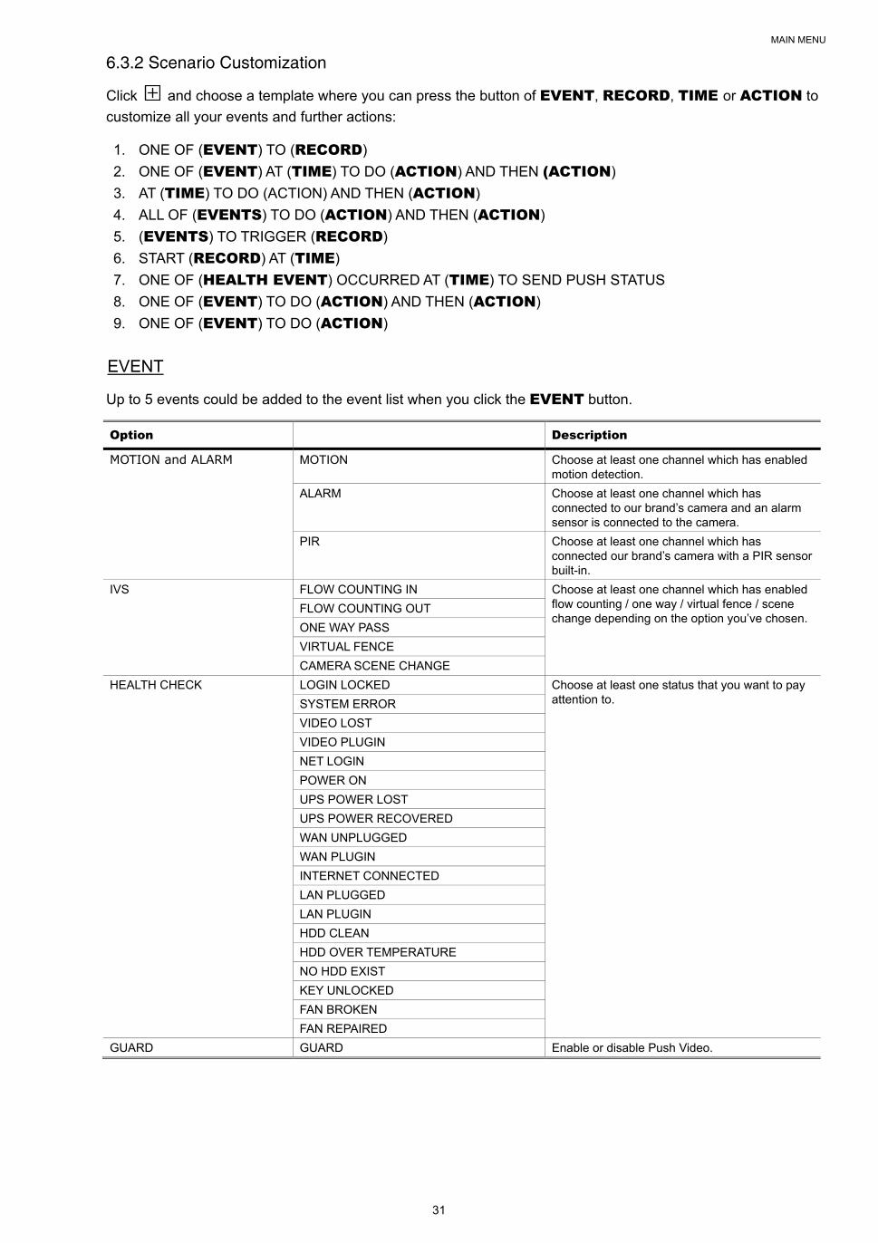
6.3.2 Scenario Customization
Click and choose a template where you can press the button of EVENT, RECORD, TIME or ACTION to
customize all your events and further actions:
1. ONE OF (EVENT) TO (RECORD)
2. ONE OF (EVENT) AT (TIME) TO DO (ACTION) AND THEN (ACTION)
3. AT (TIME) TO DO (ACTION) AND THEN (ACTION)
4. ALL OF (EVENTS) TO DO (ACTION) AND THEN (ACTION)
5. (EVENTS) TO TRIGGER (RECORD)
6. START (RECORD) AT (TIME)
7. ONE OF (HEALTH EVENT) OCCURRED AT (TIME) TO SEND PUSH STATUS
8. ONE OF (EVENT) TO DO (ACTION) AND THEN (ACTION)
9. ONE OF (EVENT) TO DO (ACTION)
EVENT
Up to 5 events could be added to the event list when you click the EVENT button.
Option Description
MOTION and ALARM MOTION Choose at least one channel which has enabled motion detection.
ALARM Choose at least one channel which has connected to our brand’s camera and an alarm sensor is connected to the camera.
PIR Choose at least one channel which has connected our brand’s camera with a PIR sensor built-in.
IVS FLOW COUNTING IN Choose at least one channel which has enabled flow counting / one way / virtual fence / scene change depending on the option you’ve chosen.
FLOW COUNTING OUT
ONE WAY PASS
VIRTUAL FENCE
CAMERA SCENE CHANGE
HEALTH CHECK LOGIN LOCKED Choose at least one status that you want to pay attention to. SYSTEM ERROR
VIDEO LOST
VIDEO PLUGIN
NET LOGIN
POWER ON
UPS POWER LOST
UPS POWER RECOVERED
WAN UNPLUGGED
WAN PLUGIN
INTERNET CONNECTED
LAN PLUGGED
LAN PLUGIN
HDD CLEAN
HDD OVER TEMPERATURE
NO HDD EXIST
KEY UNLOCKED
FAN BROKEN
FAN REPAIRED
GUARD GUARD Enable or disable Push Video.
MAIN MENU
32
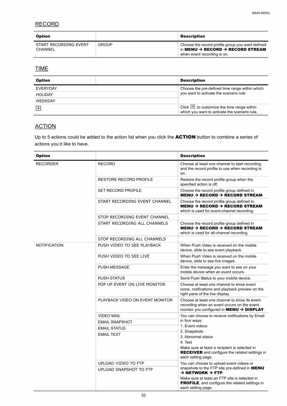
RECORD
Option Description
START RECORDING EVENT CHANNEL
GROUP Choose the record profile group you want defined in MENU RECORD RECORD STREAM when event recording is on.
TIME
Option Description
EVERYDAY Choose the pre-defined time range within which you want to activate the scenario rule. HOLIDAY
WEEKDAY
Click to customize the time range within
which you want to activate the scenario rule.
ACTION
Up to 5 actions could be added to the action list when you click the ACTION button to combine a series of
actions you’d like to have.
Option Description
RECORDER RECORD Choose at least one channel to start recording, and the record profile to use when recording is on.
RESTORE RECORD PROFILE Restore the record profile group when the specified action is off.
SET RECORD PROFILE Choose the record profile group defined in MENU RECORD RECORD STREAM.
START RECORDING EVENT CHANNEL Choose the record profile group defined in MENU RECORD RECORD STREAM which is used for event-channel recording.
STOP RECORDING EVENT CHANNEL
START RECORDING ALL CHANNELS Choose the record profile group defined in MENU RECORD RECORD STREAM which is used for all-channel recording.
STOP RECORDING ALL CHANNELS
NOTIFICATION PUSH VIDEO TO SEE PLAYBACK When Push Video is received on the mobile device, slide to see event playback.
PUSH VIDEO TO SEE LIVE When Push Video is received on the mobile device, slide to see live images.
PUSH MESSAGE Enter the message you want to see on your mobile device when an event occurs.
PUSH STATUS Send Push Status to your mobile device.
POP UP EVENT ON LIVE MONITOR Choose at least one channel to show event icons, notifications and playback preview on the right pane of the live display.
PLAYBACK VIDEO ON EVENT MONITOR Choose at least one channel to show its event recording when an event occurs on the event monitor you configured in MENU DISPLAY.
VIDEO MAIL You can choose to receive notifications by Email in four ways: 1. Event videos 2. Snapshots 3. Abnormal status 4. Text Make sure at least a recipient is selected in RECEIVER and configure the related settings in each setting page.
EMAIL SNAPSHOT
EMAIL STATUS
EMAIL TEXT
UPLOAD VIDEO TO FTP You can choose to upload event videos or snapshots to the FTP site pre-defined in MENU NETWORK FTP. Make sure at least an FTP site is selected in PROFILE, and configure the related settings in each setting page.
UPLOAD SNAPSHOT TO FTP
MAIN MENU
33
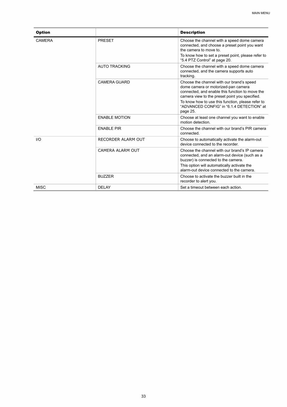
Option Description
CAMERA PRESET Choose the channel with a speed dome camera connected, and choose a preset point you want the camera to move to. To know how to set a preset point, please refer to “5.4 PTZ Control” at page 20.
AUTO TRACKING Choose the channel with a speed dome camera connected, and the camera supports auto tracking.
CAMERA GUARD Choose the channel with our brand’s speed dome camera or motorized-pan camera connected, and enable this function to move the camera view to the preset point you specified. To know how to use this function, please refer to “ADVANCED CONFIG” in “6.1.4 DETECTION” at page 25.
ENABLE MOTION Choose at least one channel you want to enable motion detection.
ENABLE PIR Choose the channel with our brand’s PIR camera connected.
I/O RECORDER ALARM OUT Choose to automatically activate the alarm-out device connected to the recorder.
CAMERA ALARM OUT Choose the channel with our brand’s IP camera connected, and an alarm-out device (such as a buzzer) is connected to the camera. This option will automatically activate the alarm-out device connected to the camera.
BUZZER Choose to activate the buzzer built in the recorder to alert you.
MISC DELAY Set a timeout between each action.

MAIN MENU
34
6.4 IVS
This function is available only when the connected IP camera supports this function.
IVS
IVS MODE DISPLAY LINE SCENE CHANGE SCENE CHANGE LEVEL SENSITIVITY
CH1 FLOW COUNTING OFF OFF MIDDLE CH2
CH3 ONEWAY OFF OFF MIDDLE CH4
1) IVS MODE
Select one of the following three modes depending on your environment:
MODE DESCRIPTION
FLOW COUNTING A virtual detection line is set to detect the moving direction of pedestrians for flow counting.
VIRTUAL FENCE A virtual detection line is set to detect intruders crossing the detection line, and an alarm will be triggered.
ONE WAY A virtual detection line is set to detect intruders from the specified direction, and an alarm will be triggered.
2) DISPLAY LINE
Select to display the detection line for IVS on the screen or not.
3) SCENE CHANGE
Select ON to trigger a motion event when the camera is sensed to be moved and the camera scene is
changed. At the same time, the icon “ ” will be also shown on the screen in addition to the motion icon “ ”.
4) SCENE CHANGE SENSITIVITY
Set the detection sensitivity for SCENE CHANGE to HIGH, MIDDLE or LOW.
5) SENSITIVITY
Set the sensitivity for IVS from 0 ~ 15. The larger the value, the more sensitive the IVS will be.
6) DISPLAY LINE
Select to display the detection line for IVS on the screen or not.
7) (Clear) & (Edit)
Select to clear the flow counting number, and to enter the setting page to set the detection line. For
details, please refer to the next section, “IVS Application”.
MAIN MENU
35
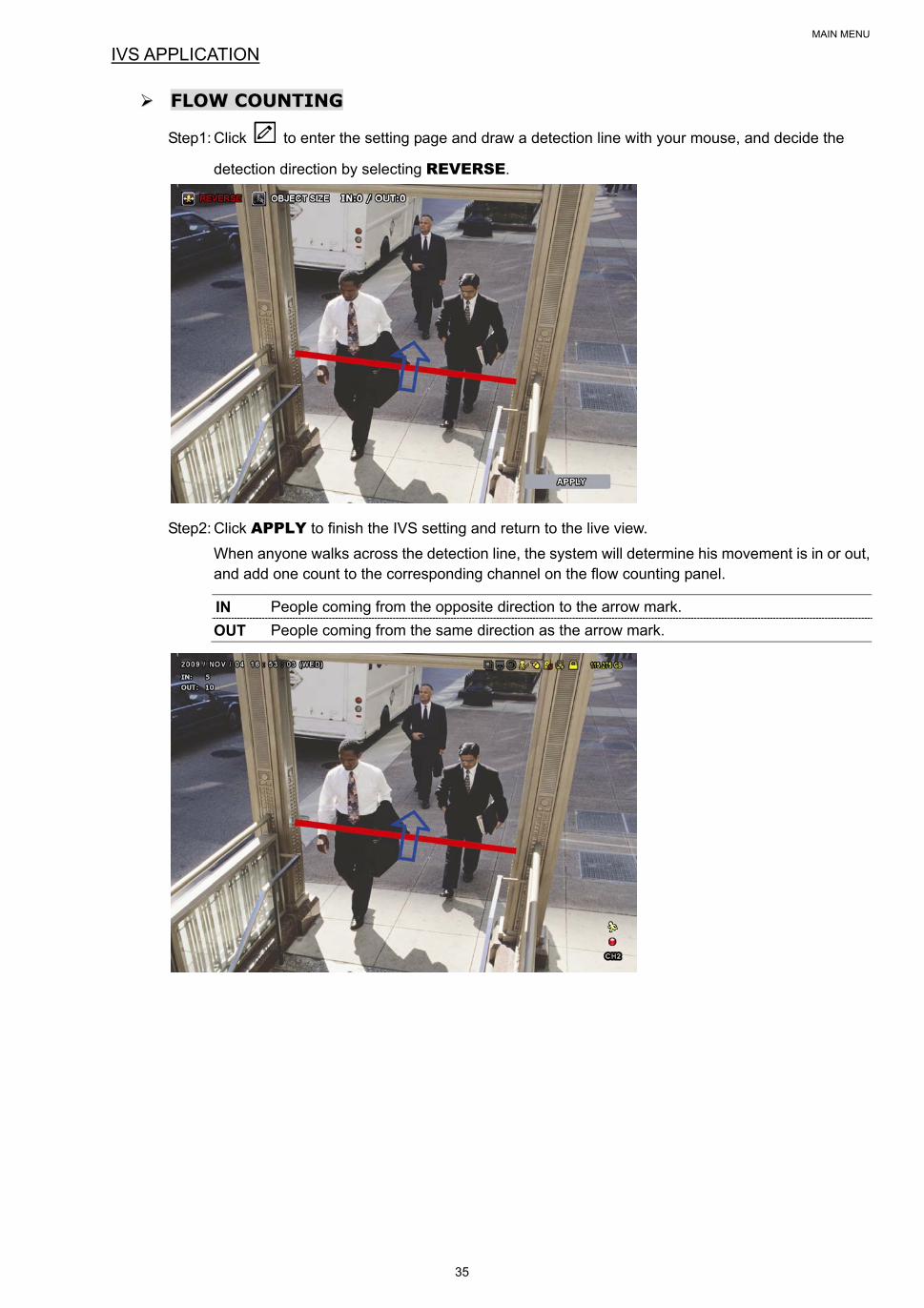
IVS APPLICATION
FFLLOOWW CCOOUUNNTTIINNGG
Step1: Click to enter the setting page and draw a detection line with your mouse, and decide the
detection direction by selecting REVERSE.
Step2: Click APPLY to finish the IVS setting and return to the live view.
When anyone walks across the detection line, the system will determine his movement is in or out, and add one count to the corresponding channel on the flow counting panel.
IN People coming from the opposite direction to the arrow mark.
OUT People coming from the same direction as the arrow mark.
MAIN MENU
36
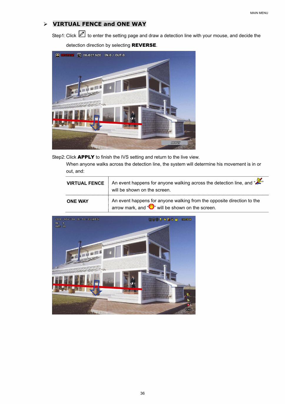
VVIIRRTTUUAALL FFEENNCCEE aanndd OONNEE WWAAYY
Step1: Click to enter the setting page and draw a detection line with your mouse, and decide the
detection direction by selecting REVERSE.
Step2: Click APPLY to finish the IVS setting and return to the live view.
When anyone walks across the detection line, the system will determine his movement is in or
out, and:
VIRTUAL FENCE An event happens for anyone walking across the detection line, and “ ”
will be shown on the screen.
ONE WAY An event happens for anyone walking from the opposite direction to the
arrow mark, and “ ” will be shown on the screen.
MAIN MENU
37
6.5 EXPORT
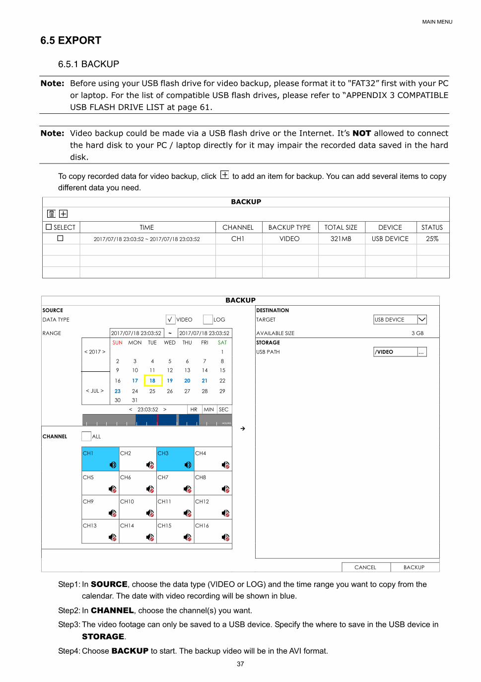
6.5.1 BACKUP
Note: Before using your USB flash drive for video backup, please format it to "FAT32” first with your PC or laptop. For the list of compatible USB flash drives, please refer to “APPENDIX 3 COMPATIBLE USB FLASH DRIVE LIST at page 61.
Note: Video backup could be made via a USB flash drive or the Internet. It’s NOT allowed to connect the hard disk to your PC / laptop directly for it may impair the recorded data saved in the hard disk.
To copy recorded data for video backup, click to add an item for backup. You can add several items to copy
different data you need.
BACKUP
SELECT TIME CHANNEL BACKUP TYPE TOTAL SIZE DEVICE STATUS 2017/07/18 23:03:52 ~ 2017/07/18 23:03:52 CH1 VIDEO 321MB USB DEVICE 25%
BACKUP SOURCE DESTINATION DATA TYPE √ VIDEO LOG TARGET USB DEVICE RANGE 2017/07/18 23:03:52 ~ 2017/07/18 23:03:52 AVAILABLE SIZE 3 GB
< 2017 >
< JUL >
SUN MON TUE WED THU FRI SAT STORAGE
1 USB PATH /VIDEO …
2 3 4 5 6 7 8 9 10 11 12 13 14 15
16 17 18 19 20 21 22
23 24 25 26 27 28 29 30 31
< 23:03:52 > HR MIN SEC
HOURS
CHANNEL ALL CH1
CH2
CH3
CH4
CH5
CH6
CH7
CH8
CH9
CH10
CH11
CH12
CH13
CH14
CH15
CH16
CANCEL BACKUP
Step1: In SOURCE, choose the data type (VIDEO or LOG) and the time range you want to copy from the
calendar. The date with video recording will be shown in blue.
Step2: In CHANNEL, choose the channel(s) you want.
Step3: The video footage can only be saved to a USB device. Specify the where to save in the USB device in
STORAGE.
Step4: Choose BACKUP to start. The backup video will be in the AVI format.
MAIN MENU
38
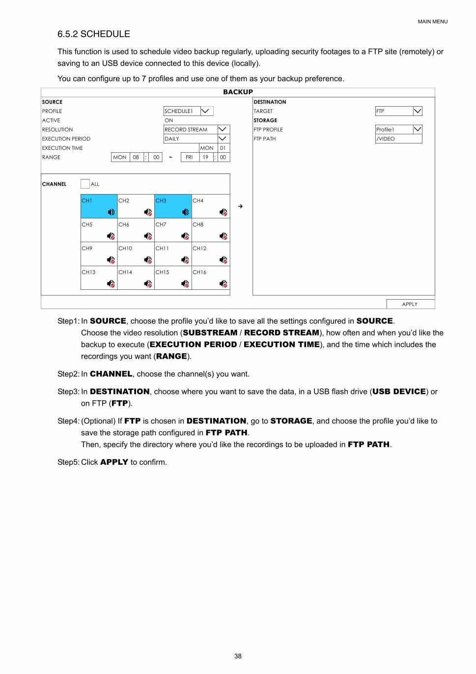
6.5.2 SCHEDULE
This function is used to schedule video backup regularly, uploading security footages to a FTP site (remotely) or
saving to an USB device connected to this device (locally).
You can configure up to 7 profiles and use one of them as your backup preference.
BACKUP SOURCE DESTINATION PROFILE SCHEDULE1 TARGET FTP
ACTIVE ON STORAGE
RESOLUTION RECORD STREAM FTP PROFILE Profile1
EXECUTION PERIOD DAILY FTP PATH /VIDEO
EXECUTION TIME MON 01
RANGE MON 08 : 00 ~ FRI 19 : 00
CHANNEL ALL CH1
CH2
CH3
CH4
CH5
CH6
CH7
CH8
CH9
CH10
CH11
CH12
CH13
CH14
CH15
CH16
APPLY
Step1: In SOURCE, choose the profile you’d like to save all the settings configured in SOURCE.
Choose the video resolution (SUBSTREAM / RECORD STREAM), how often and when you’d like the
backup to execute (EXECUTION PERIOD / EXECUTION TIME), and the time which includes the
recordings you want (RANGE).
Step2: In CHANNEL, choose the channel(s) you want.
Step3: In DESTINATION, choose where you want to save the data, in a USB flash drive (USB DEVICE) or
on FTP (FTP).
Step4: (Optional) If FTP is chosen in DESTINATION, go to STORAGE, and choose the profile you’d like to
save the storage path configured in FTP PATH.
Then, specify the directory where you’d like the recordings to be uploaded in FTP PATH.
Step5: Click APPLY to confirm.
MAIN MENU
39
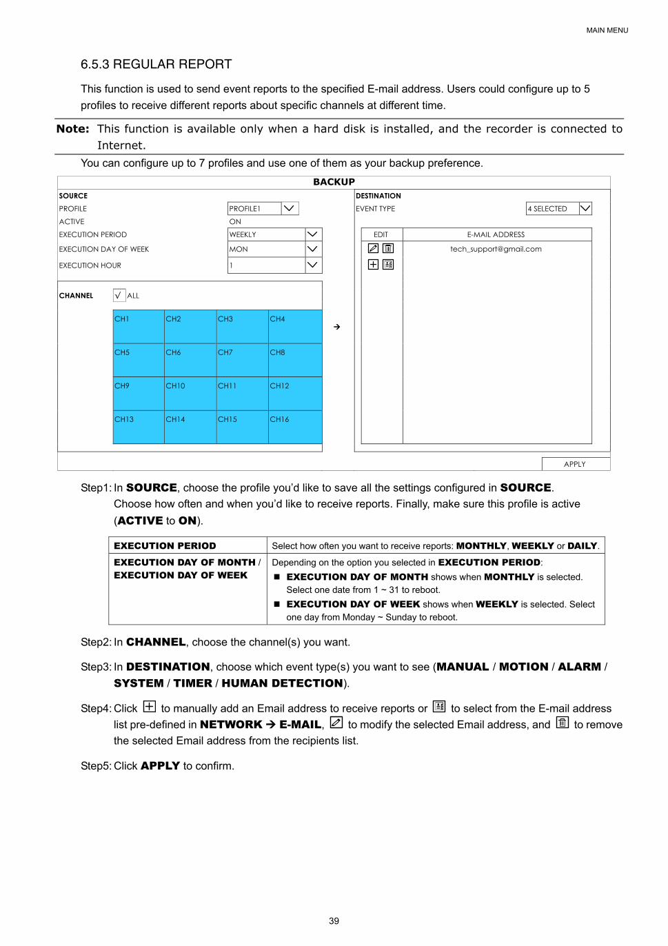
6.5.3 REGULAR REPORT
This function is used to send event reports to the specified E-mail address. Users could configure up to 5
profiles to receive different reports about specific channels at different time.
Note: This function is available only when a hard disk is installed, and the recorder is connected to Internet.
You can configure up to 7 profiles and use one of them as your backup preference.
BACKUP SOURCE DESTINATION PROFILE PROFILE1 EVENT TYPE 4 SELECTED
ACTIVE ON
EXECUTION PERIOD WEEKLY EDIT E-MAIL ADDRESS
EXECUTION DAY OF WEEK MON
EXECUTION HOUR 1
CHANNEL √ ALL CH1
CH2
CH3
CH4
CH5
CH6
CH7
CH8
CH9
CH10
CH11
CH12
CH13
CH14
CH15
CH16
APPLY
Step1: In SOURCE, choose the profile you’d like to save all the settings configured in SOURCE.
Choose how often and when you’d like to receive reports. Finally, make sure this profile is active
(ACTIVE to ON).
EXECUTION PERIOD Select how often you want to receive reports: MONTHLY, WEEKLY or DAILY.
EXECUTION DAY OF MONTH /
EXECUTION DAY OF WEEK
Depending on the option you selected in EXECUTION PERIOD:
EXECUTION DAY OF MONTH shows when MONTHLY is selected.
Select one date from 1 ~ 31 to reboot.
EXECUTION DAY OF WEEK shows when WEEKLY is selected. Select
one day from Monday ~ Sunday to reboot.
Step2: In CHANNEL, choose the channel(s) you want.
Step3: In DESTINATION, choose which event type(s) you want to see (MANUAL / MOTION / ALARM /
SYSTEM / TIMER / HUMAN DETECTION).
Step4: Click to manually add an Email address to receive reports or to select from the E-mail address
list pre-defined in NETWORK E-MAIL, to modify the selected Email address, and to remove
the selected Email address from the recipients list.
Step5: Click APPLY to confirm.

MAIN MENU
40
6.6 STORAGE
To copy recorded data for video backup, click to add an item for backup. You can add several items to copy
different data you need.
STORAGE HDD NEARLY FULL (GB) 5 HDD OVERHEAT ALERT (°C) 70 OVERWRITE ON KEEP DATA LIMIT(DAYS) OFF TEMPERATURE TO ENABLE FAN 30
ID TYPE STATUS SIZE TEMP. SERIAL NUMBER FREE SIZE FORMAT TIME HEALTH STATUS
HDD 5-1 NORMAL READY 750GB 33°C WD-WCAV53797317 269.856GB 2017/07/18 23:03:52 GOOD
1) HDD NEARLY FULL (GB)
If HDD BUZZER is enabled in MAINTAIN, select the duration time for buzzer notifications when the hard
disk available capacity is 5/10/15/20 GB left.
2) HDD OVERHEAT ALERT (°C)
Select the temperature alert for your hard disk to be aware of the possible overheat of your hard disk.
3) OVERWRITE
Be defaults, the HDD overwritten function is set to ON, and will be shown on the screen.
4) KEEP DATA LIMITS (DAYS)
Assign how many days to save the recording data from 1 to 31 days. After the assigned day(s), the recorded
data will be removed. Select OFF to disable this function.
5) TEMPERATURE TO ENABLE FAN
Choose the temperature (25 / 30 / 35 / 40) to enable the built-in fan to work for heat dissipation.
6) HDD information
You can check the remaining capacity of the connected hard disk in this device and its current status.
If the health status goes to:
GOOD - This hard disk works normal.
BELOW AVERAGE - The hard disk might work with some errors. Please pay attention and do video backup if
needed.
REPLACEMENT NEEDED – Please replace this hard disk immediately to ensure continuous video recording.
7) HDD details
You can check the details of the selected hard disk.
8) HDD formation
Click to format the selected hard disk and erase all data. When a hard disk is inserted to the recorder for the
first time, it’s compulsory to format the hard disk for it to work properly.
9) Mount / Unmount HDD
HDD hot-swapping is supported for this device. There’s no need to power off the device first to install or
remove a hard disk.
When a hard disk is installed, you’ll need to click to manually mount the hard disk for it to work properly.
When you need to remove a hard disk, click to unmount the hard disk and you’ll be able to remove it.
Note: It’s not allowed to remove a hard disk without clicking first.
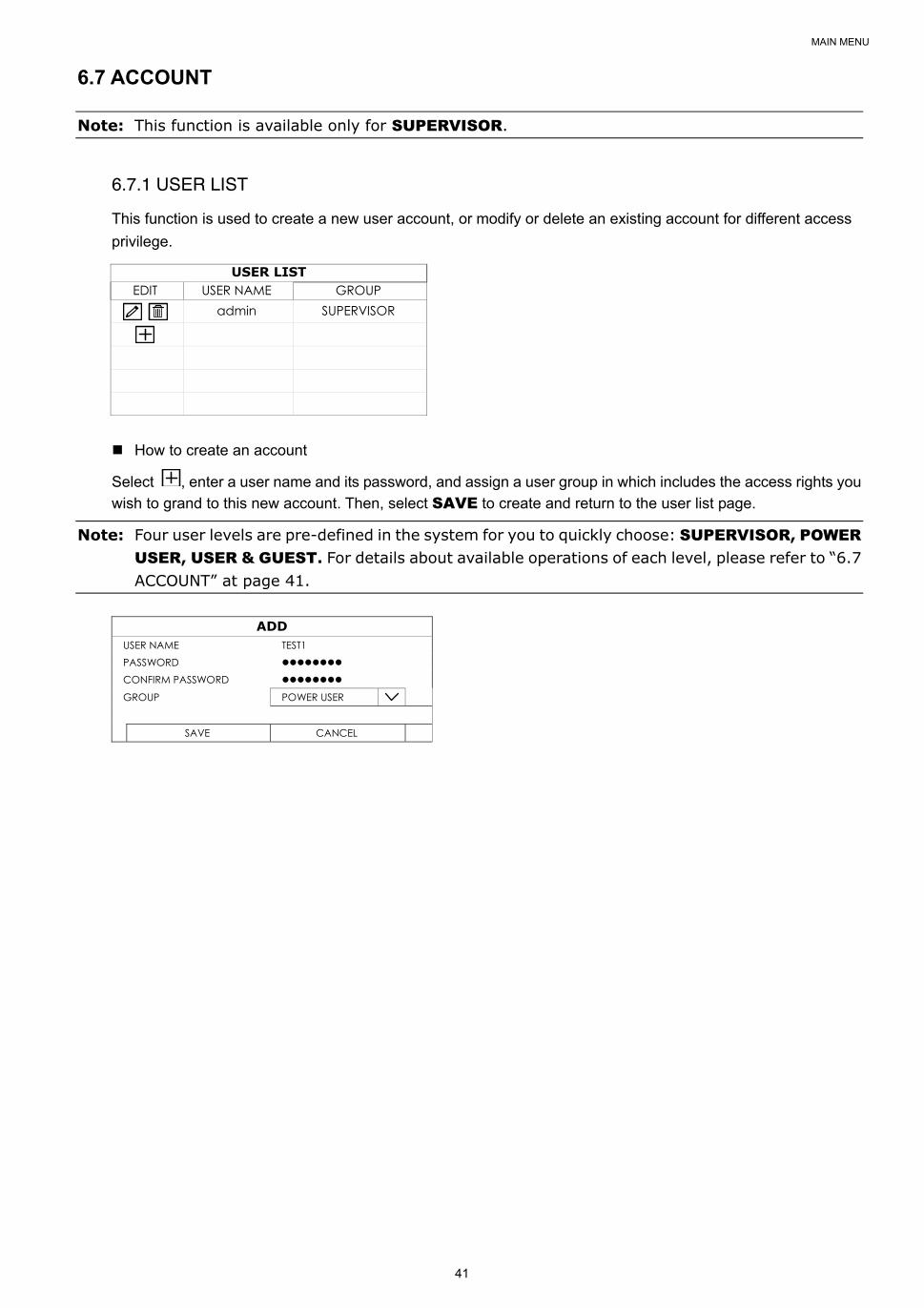
MAIN MENU
41
6.7 ACCOUNT
Note: This function is available only for SUPERVISOR.
6.7.1 USER LIST
This function is used to create a new user account, or modify or delete an existing account for different access
privilege.
USER LIST EDIT USER NAME GROUP
admin SUPERVISOR
How to create an account
Select , enter a user name and its password, and assign a user group in which includes the access rights you
wish to grand to this new account. Then, select SAVE to create and return to the user list page.
Note: Four user levels are pre-defined in the system for you to quickly choose: SUPERVISOR, POWER USER, USER & GUEST. For details about available operations of each level, please refer to “6.7 ACCOUNT” at page 41.
ADD
USER NAME TEST1 PASSWORD CONFIRM PASSWORD
GROUP POWER USER
SAVE CANCEL
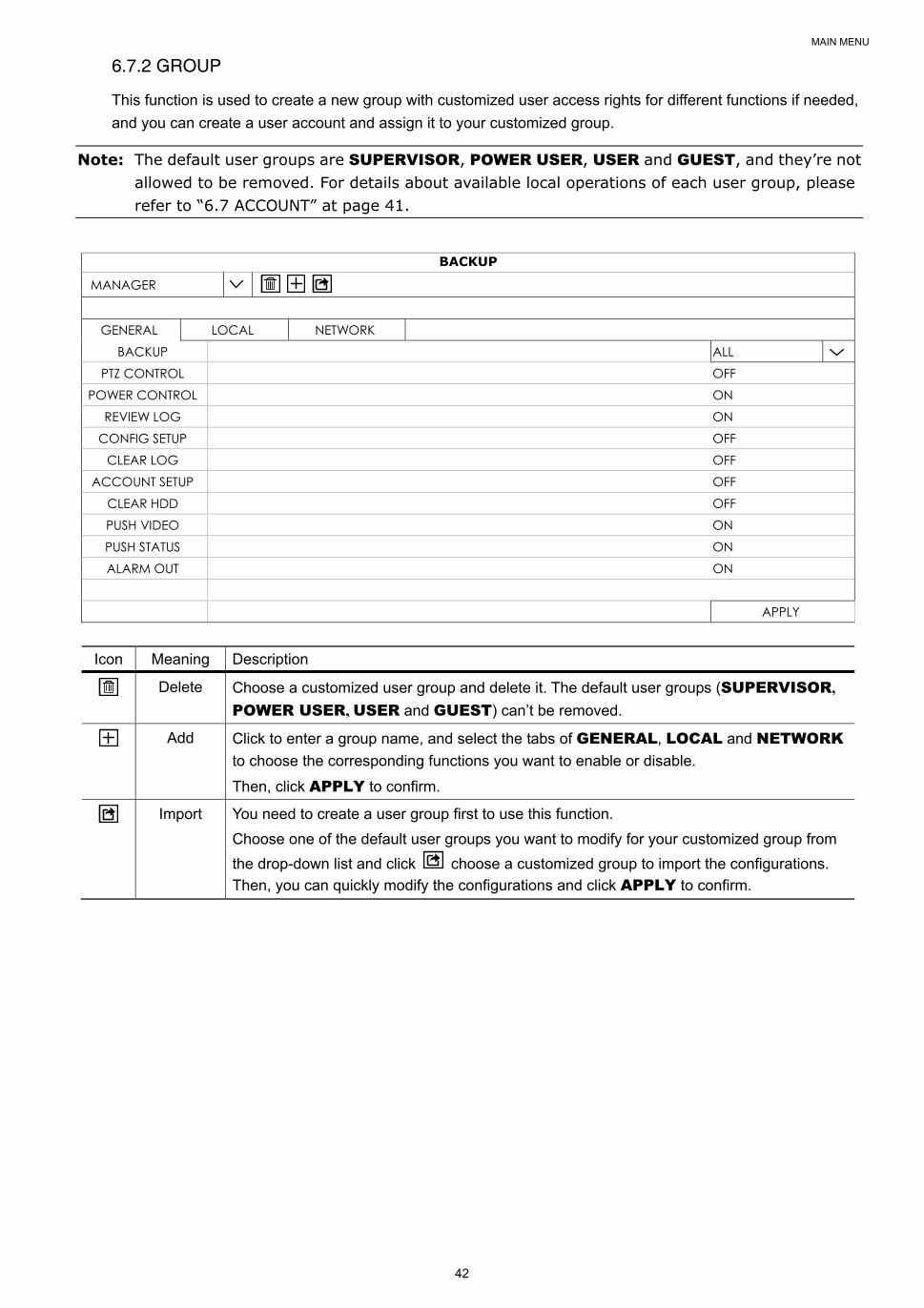
MAIN MENU
42
6.7.2 GROUP
This function is used to create a new group with customized user access rights for different functions if needed,
and you can create a user account and assign it to your customized group.
Note: The default user groups are SUPERVISOR, POWER USER, USER and GUEST, and they’re not allowed to be removed. For details about available local operations of each user group, please refer to “6.7 ACCOUNT” at page 41.
BACKUP
MANAGER
GENERAL LOCAL NETWORK BACKUP ALL
PTZ CONTROL OFF POWER CONTROL ON
REVIEW LOG ON CONFIG SETUP OFF
CLEAR LOG OFF ACCOUNT SETUP OFF
CLEAR HDD OFF PUSH VIDEO ON PUSH STATUS ON ALARM OUT ON
APPLY
Icon Meaning Description
Delete Choose a customized user group and delete it. The default user groups (SUPERVISOR,
POWER USER, USER and GUEST) can’t be removed.
Add Click to enter a group name, and select the tabs of GENERAL, LOCAL and NETWORK
to choose the corresponding functions you want to enable or disable.
Then, click APPLY to confirm.
Import You need to create a user group first to use this function.
Choose one of the default user groups you want to modify for your customized group from
the drop-down list and click choose a customized group to import the configurations.
Then, you can quickly modify the configurations and click APPLY to confirm.
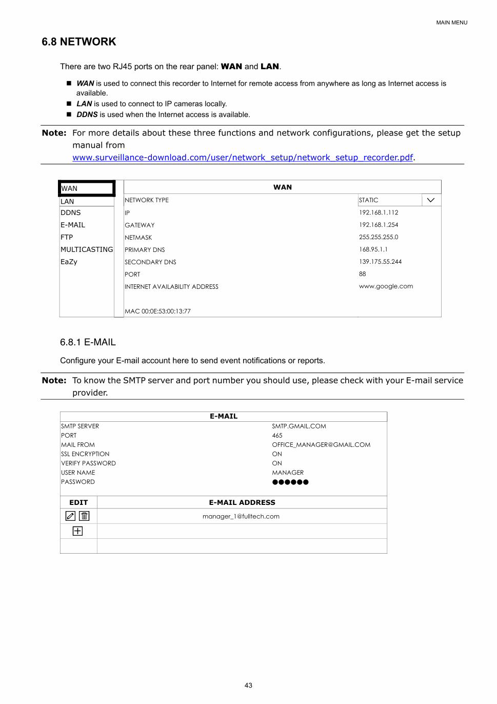
MAIN MENU
43
6.8 NETWORK
There are two RJ45 ports on the rear panel: WAN and LAN.
WAN is used to connect this recorder to Internet for remote access from anywhere as long as Internet access is available.
LAN is used to connect to IP cameras locally.
DDNS is used when the Internet access is available.
Note: For more details about these three functions and network configurations, please get the setup manual from www.surveillance-download.com/user/network_setup/network_setup_recorder.pdf.
WAN WAN
LAN NETWORK TYPE STATIC
DDNS IP 192.168.1.112
E-MAIL GATEWAY 192.168.1.254
FTP NETMASK 255.255.255.0
MULTICASTING PRIMARY DNS 168.95.1.1
EaZy SECONDARY DNS 139.175.55.244
PORT 88
INTERNET AVAILABILITY ADDRESS www.google.com
MAC 00:0E:53:00:13:77
6.8.1 E-MAIL
Configure your E-mail account here to send event notifications or reports.
Note: To know the SMTP server and port number you should use, please check with your E-mail service provider.
SMTP SERVER SMTP.GMAIL.COM PORT 465 MAIL FROM [email protected] SSL ENCRYPTION ON VERIFY PASSWORD ON USER NAME MANAGER PASSWORD ●●●●●●
EDIT E-MAIL ADDRESS

MAIN MENU
44
6.8.2 FTP
Configure up to 7 FTP sites here to upload event notifications or reports.
FTP FTP 1 FTP 2 FTP 3 FTP 4 FTP 5 FTP 6 FTP 7
NAME Profile1 SERVER 211.75.33.2144 PORT 25 USER NAME office PASSWORD
APPLY
6.8.3 MULTICASTING
In this menu, users could configure the multicast address and port used for each channel for data streaming.
Three streams for different usage could be configured per channel. These are used for different video data
requests from different clients.
MULTICASTING TIMEOUT (SECS) 50 LIMIT THE TRANSFERING OF THE RECORDING STREAM 2
MULTICAST STREAM 1 ADDRESS
MULTICAST SREAM 1 PORT
STREAM 1 TIME TO LIVE(TTL)
MULTICAST STREAM 2 ADDRESS
MULTICAST SREAM 2 PORT
STREAM 2 TIME TO LIVE(TTL)
MULTICAST STREAM 3 ADDRESS
MULTICAST SREAM 3 PORT
STREAM 3 TIME TO LIVE(TTL)
CH1 239.0.0.1 9000 15 239.0.0.2 9002 15 239.0.0.3 9004 15 CH2 239.0.0.1 9006 15 239.0.0.2 9008 15 239.0.0.3 9010 15 CH3 239.0.0.1 9012 15 239.0.0.2 9014 15 239.0.0.3 9016 15 CH4 239.0.0.1 9018 15 239.0.0.2 9020 15 239.0.0.3 9022 15
1) TIMEOUT (SECS)
Set the timeout in second for transmission attempt in second for this channel, after which the attempt will be
down. The options are: 10 / 20 / 30 / 50 / 120 / 240 / 300.
2) LIMIT THE TRANSFERING OF THE RECORDING STREAM
Set the number of how many record streaming could be transferred at the same time.
3) MULTICAST STREAM ADDRESS
Configure the addresses used for the three streams per channel.
The address range for multicasting is from 224.0.0.0 to 239.255.255.255.
Note: The address for each stream per channel should be unique and can’t be the same as other stream in the same channel or other channel.
4) MULTICAST STREAM PORT
Set the event recording function on / off.
Configure the ports used for the three streams per channel.
The port range is from 1 to 65535.
Note: The port for each stream per channel should be unique and can’t be the same as other stream in the same channel or other channel.
5) TIME TO LIVE(TTL)
Set the connection time in second for each stream from 1 ~ 999.
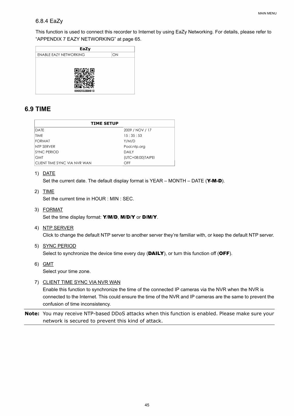
MAIN MENU
45
6.8.4 EaZy
This function is used to connect this recorder to Internet by using EaZy Networking. For details, please refer to
“APPENDIX 7 EAZY NETWORKING” at page 65.
EaZy ENABLE EAZY NETWORKING ON
6.9 TIME
TIME SETUP DATE 2009 / NOV / 17 TIME 15 : 35 : 53 FORMAT Y/M/D NTP SERVER Pool.ntp.org SYNC PERIOD DAILY GMT (UTC+08:00)TAIPEI CLIENT TIME SYNC VIA NVR WAN OFF
1) DATE
Set the current date. The default display format is YEAR – MONTH – DATE (Y-M-D).
2) TIME
Set the current time in HOUR : MIN : SEC.
3) FORMAT
Set the time display format: Y/M/D, M/D/Y or D/M/Y.
4) NTP SERVER
Click to change the default NTP server to another server they’re familiar with, or keep the default NTP server.
5) SYNC PERIOD
Select to synchronize the device time every day (DAILY), or turn this function off (OFF).
6) GMT
Select your time zone.
7) CLIENT TIME SYNC VIA NVR WAN
Enable this function to synchronize the time of the connected IP cameras via the NVR when the NVR is
connected to the Internet. This could ensure the time of the NVR and IP cameras are the same to prevent the
confusion of time inconsistency.
Note: You may receive NTP-based DDoS attacks when this function is enabled. Please make sure your network is secured to prevent this kind of attack.
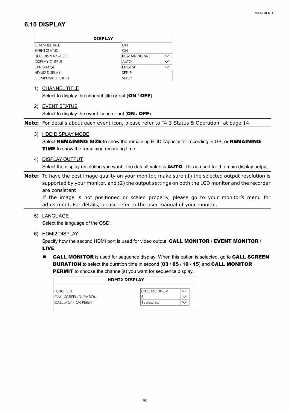
MAIN MENU
46
6.10 DISPLAY
DISPLAY CHANNEL TITLE ON EVENT STATUS ON HDD DISPLAY MODE RE,MAINING SIZE DISPLAY OUTPUT AUTO LANGUAGE ENGLISH HDMI2 DISPLAY SETUP COMPOSITE OUTPUT SETUP
1) CHANNEL TITLE
Select to display the channel title or not (ON / OFF).
2) EVENT STATUS
Select to display the event icons or not (ON / OFF).
Note: For details about each event icon, please refer to “4.3 Status & Operation” at page 14.
3) HDD DISPLAY MODE
Select REMAINING SIZE to show the remaining HDD capacity for recording in GB, or REMAINING TIME to show the remaining recording time.
4) DISPLAY OUTPUT
Select the display resolution you want. The default value is AUTO. This is used for the main display output.
Note: To have the best image quality on your monitor, make sure (1) the selected output resolution is supported by your monitor, and (2) the output settings on both the LCD monitor and the recorder are consistent. If the image is not positioned or scaled properly, please go to your monitor’s menu for adjustment. For details, please refer to the user manual of your monitor.
5) LANGUAGE
Select the language of the OSD.
6) HDMI2 DISPLAY
Specify how the second HDMI port is used for video output: CALL MONITOR / EVENT MONITOR /
LIVE.
CALL MONITOR is used for sequence display. When this option is selected, go to CALL SCREEN DURATION to select the duration time in second (03 / 05 / 10 / 15) and CALL MONITOR PERMIT to choose the channel(s) you want for sequence display.
HDMI2 DISPLAY
FUNCTION CALL MONITOR CALL SCREEN DURATION 5 CALL MONITOR PERMIT 4 selected
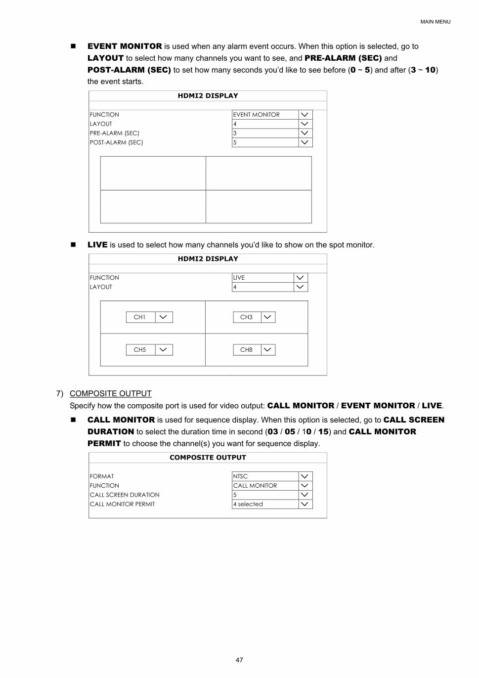
MAIN MENU
47
EVENT MONITOR is used when any alarm event occurs. When this option is selected, go to
LAYOUT to select how many channels you want to see, and PRE-ALARM (SEC) and
POST-ALARM (SEC) to set how many seconds you’d like to see before (0 ~ 5) and after (3 ~ 10)
the event starts.
HDMI2 DISPLAY
FUNCTION EVENT MONITOR LAYOUT 4 PRE-ALARM (SEC) 3 POST-ALARM (SEC) 5
LIVE is used to select how many channels you’d like to show on the spot monitor.
HDMI2 DISPLAY
FUNCTION LIVE LAYOUT 4
CH1 CH3
CH5 CH8
7) COMPOSITE OUTPUT
Specify how the composite port is used for video output: CALL MONITOR / EVENT MONITOR / LIVE.
CALL MONITOR is used for sequence display. When this option is selected, go to CALL SCREEN DURATION to select the duration time in second (03 / 05 / 10 / 15) and CALL MONITOR PERMIT to choose the channel(s) you want for sequence display.
COMPOSITE OUTPUT FORMAT NTSC FUNCTION CALL MONITOR CALL SCREEN DURATION 5 CALL MONITOR PERMIT 4 selected
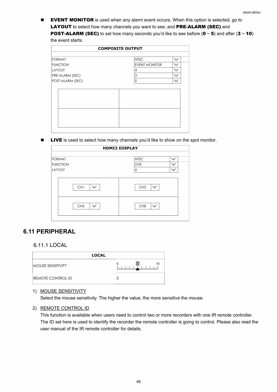
MAIN MENU
48
EVENT MONITOR is used when any alarm event occurs. When this option is selected, go to
LAYOUT to select how many channels you want to see, and PRE-ALARM (SEC) and
POST-ALARM (SEC) to set how many seconds you’d like to see before (0 ~ 5) and after (3 ~ 10)
the event starts.
COMPOSITE OUTPUT
FORMAT NTSC FUNCTION EVENT MONITOR LAYOUT 4 PRE-ALARM (SEC) 3 POST-ALARM (SEC) 5
LIVE is used to select how many channels you’d like to show on the spot monitor.
HDMI2 DISPLAY
FORMAT NTSC FUNCTION LIVE LAYOUT 4
CH1 CH3
CH5 CH8
6.11 PERIPHERAL
6.11.1 LOCAL
LOCAL
MOUSE SENSITIVITY 0 5 10
REMOTE CONTROL ID 0
1) MOUSE SENSITIVITY
Select the mouse sensitivity. The higher the value, the more sensitive the mouse.
2) REMOTE CONTROL ID
This function is available when users need to control two or more recorders with one IR remote controller.
The ID set here is used to identify the recorder the remote controller is going to control. Please also read the
user manual of the IR remote controller for details.
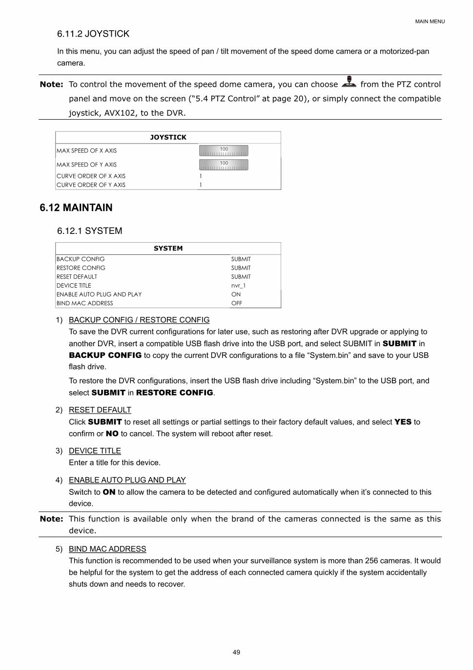
MAIN MENU
49
6.11.2 JOYSTICK
In this menu, you can adjust the speed of pan / tilt movement of the speed dome camera or a motorized-pan
camera.
Note: To control the movement of the speed dome camera, you can choose from the PTZ control
panel and move on the screen (“5.4 PTZ Control” at page 20), or simply connect the compatible
joystick, AVX102, to the DVR.
JOYSTICK
MAX SPEED OF X AXIS 100
MAX SPEED OF Y AXIS 100
CURVE ORDER OF X AXIS 1 CURVE ORDER OF Y AXIS 1
6.12 MAINTAIN
6.12.1 SYSTEM
SYSTEM BACKUP CONFIG SUBMIT RESTORE CONFIG SUBMIT RESET DEFAULT SUBMIT DEVICE TITLE nvr_1 ENABLE AUTO PLUG AND PLAY ON BIND MAC ADDRESS OFF
1) BACKUP CONFIG / RESTORE CONFIG
To save the DVR current configurations for later use, such as restoring after DVR upgrade or applying to
another DVR, insert a compatible USB flash drive into the USB port, and select SUBMIT in SUBMIT in
BACKUP CONFIG to copy the current DVR configurations to a file “System.bin” and save to your USB
flash drive.
To restore the DVR configurations, insert the USB flash drive including “System.bin” to the USB port, and
select SUBMIT in RESTORE CONFIG.
2) RESET DEFAULT
Click SUBMIT to reset all settings or partial settings to their factory default values, and select YES to
confirm or NO to cancel. The system will reboot after reset.
3) DEVICE TITLE
Enter a title for this device.
4) ENABLE AUTO PLUG AND PLAY
Switch to ON to allow the camera to be detected and configured automatically when it’s connected to this
device.
Note: This function is available only when the brand of the cameras connected is the same as this device.
5) BIND MAC ADDRESS
This function is recommended to be used when your surveillance system is more than 256 cameras. It would
be helpful for the system to get the address of each connected camera quickly if the system accidentally
shuts down and needs to recover.
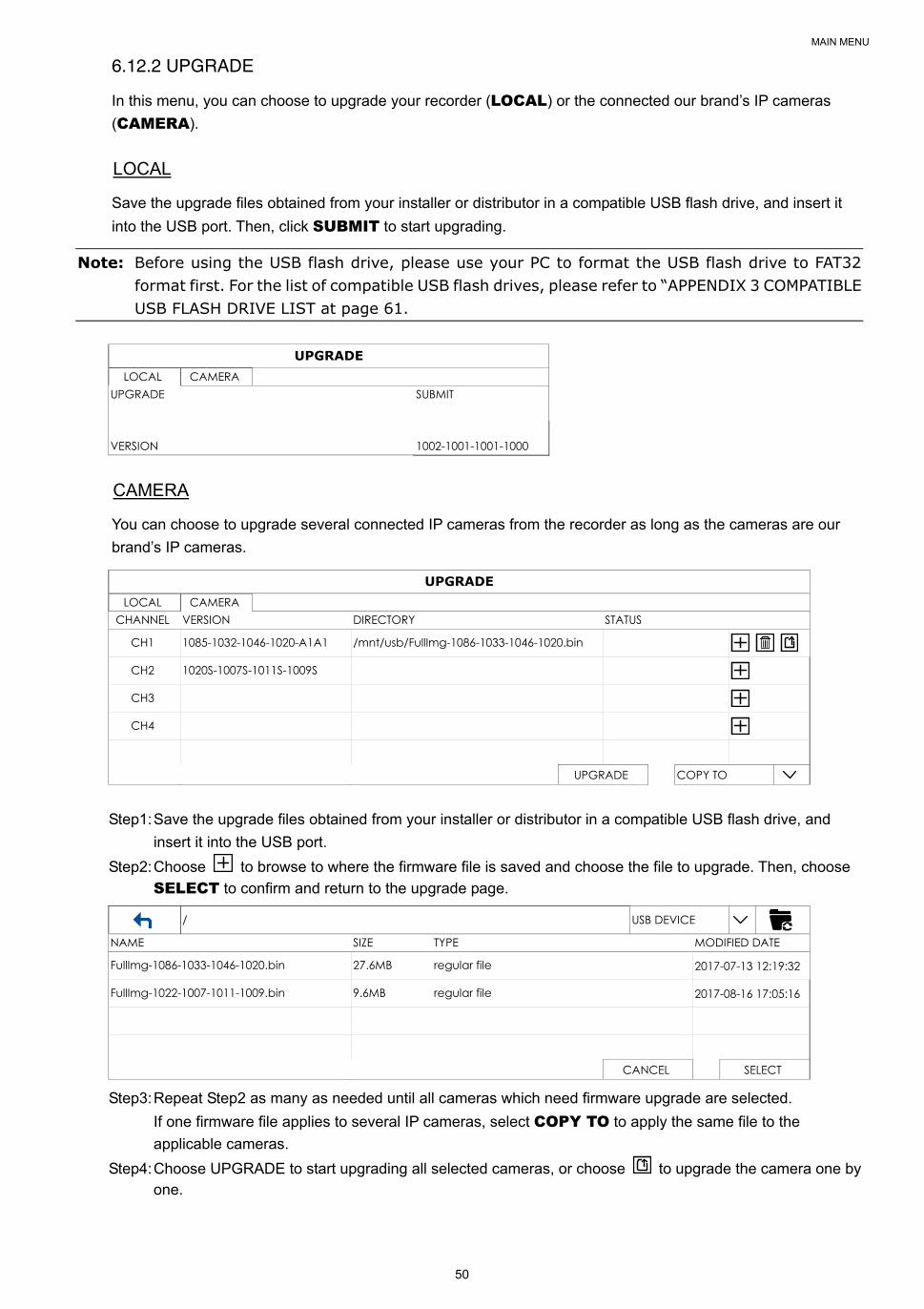
MAIN MENU
50
6.12.2 UPGRADE
In this menu, you can choose to upgrade your recorder (LOCAL) or the connected our brand’s IP cameras
(CAMERA).
LOCAL
Save the upgrade files obtained from your installer or distributor in a compatible USB flash drive, and insert it
into the USB port. Then, click SUBMIT to start upgrading.
Note: Before using the USB flash drive, please use your PC to format the USB flash drive to FAT32 format first. For the list of compatible USB flash drives, please refer to “APPENDIX 3 COMPATIBLE USB FLASH DRIVE LIST at page 61.
UPGRADE LOCAL CAMERA
UPGRADE SUBMIT VERSION 1002-1001-1001-1000
CAMERA
You can choose to upgrade several connected IP cameras from the recorder as long as the cameras are our
brand’s IP cameras.
UPGRADE LOCAL CAMERA
CHANNEL VERSION DIRECTORY STATUS
CH1 1085-1032-1046-1020-A1A1 /mnt/usb/FullImg-1086-1033-1046-1020.bin
CH2 1020S-1007S-1011S-1009S
CH3
CH4
UPGRADE COPY TO
Step1: Save the upgrade files obtained from your installer or distributor in a compatible USB flash drive, and
insert it into the USB port.
Step2: Choose to browse to where the firmware file is saved and choose the file to upgrade. Then, choose
SELECT to confirm and return to the upgrade page.
/ USB DEVICE NAME SIZE TYPE MODIFIED DATE
FullImg-1086-1033-1046-1020.bin 27.6MB regular file 2017-07-13 12:19:32
FullImg-1022-1007-1011-1009.bin 9.6MB regular file 2017-08-16 17:05:16
CANCEL SELECT
Step3: Repeat Step2 as many as needed until all cameras which need firmware upgrade are selected.
If one firmware file applies to several IP cameras, select COPY TO to apply the same file to the
applicable cameras.
Step4: Choose UPGRADE to start upgrading all selected cameras, or choose to upgrade the camera one by one.
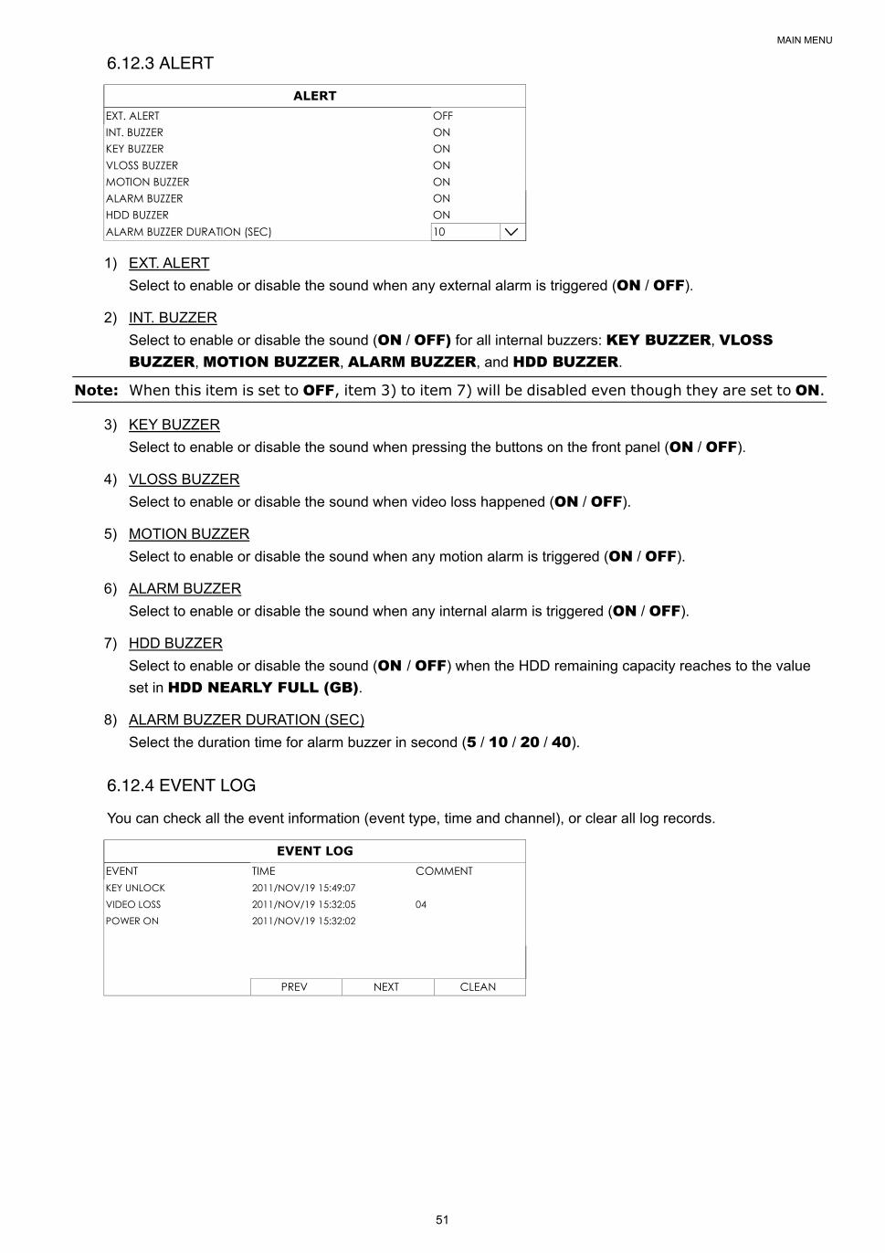
MAIN MENU
51
6.12.3 ALERT
ALERT EXT. ALERT OFF INT. BUZZER ON KEY BUZZER ON VLOSS BUZZER ON MOTION BUZZER ON ALARM BUZZER ON HDD BUZZER ON ALARM BUZZER DURATION (SEC) 10
1) EXT. ALERT
Select to enable or disable the sound when any external alarm is triggered (ON / OFF).
2) INT. BUZZER
Select to enable or disable the sound (ON / OFF) for all internal buzzers: KEY BUZZER, VLOSS BUZZER, MOTION BUZZER, ALARM BUZZER, and HDD BUZZER.
Note: When this item is set to OFF, item 3) to item 7) will be disabled even though they are set to ON.
3) KEY BUZZER
Select to enable or disable the sound when pressing the buttons on the front panel (ON / OFF).
4) VLOSS BUZZER
Select to enable or disable the sound when video loss happened (ON / OFF).
5) MOTION BUZZER
Select to enable or disable the sound when any motion alarm is triggered (ON / OFF).
6) ALARM BUZZER
Select to enable or disable the sound when any internal alarm is triggered (ON / OFF).
7) HDD BUZZER
Select to enable or disable the sound (ON / OFF) when the HDD remaining capacity reaches to the value
set in HDD NEARLY FULL (GB).
8) ALARM BUZZER DURATION (SEC)
Select the duration time for alarm buzzer in second (5 / 10 / 20 / 40).
6.12.4 EVENT LOG
You can check all the event information (event type, time and channel), or clear all log records.
EVENT LOG EVENT TIME COMMENT KEY UNLOCK 2011/NOV/19 15:49:07 VIDEO LOSS 2011/NOV/19 15:32:05 04 POWER ON 2011/NOV/19 15:32:02 PREV NEXT CLEAN
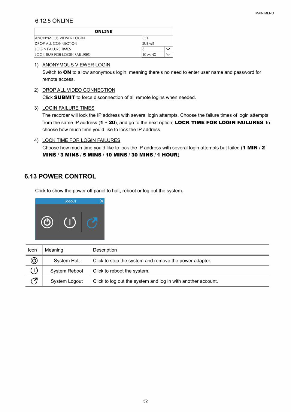
MAIN MENU
52
6.12.5 ONLINE
ONLINE ANONYMOUS VIEWER LOGIN OFF DROP ALL CONNECTION SUBMIT LOGIN FAILURE TIMES 3 LOCK TIME FOR LOGIN FAILURES 10 MINS
1) ANONYMOUS VIEWER LOGIN
Switch to ON to allow anonymous login, meaning there’s no need to enter user name and password for
remote access.
2) DROP ALL VIDEO CONNECTION
Click SUBMIT to force disconnection of all remote logins when needed.
3) LOGIN FAILURE TIMES
The recorder will lock the IP address with several login attempts. Choose the failure times of login attempts
from the same IP address (1 ~ 20), and go to the next option, LOCK TIME FOR LOGIN FAILURES, to
choose how much time you’d like to lock the IP address.
4) LOCK TIME FOR LOGIN FAILURES
Choose how much time you’d like to lock the IP address with several login attempts but failed (1 MIN / 2 MINS / 3 MINS / 5 MINS / 10 MINS / 30 MINS / 1 HOUR).
6.13 POWER CONTROL
Click to show the power off panel to halt, reboot or log out the system.
Icon Meaning Description
System Halt Click to stop the system and remove the power adapter.
System Reboot Click to reboot the system.
System Logout Click to log out the system and log in with another account.
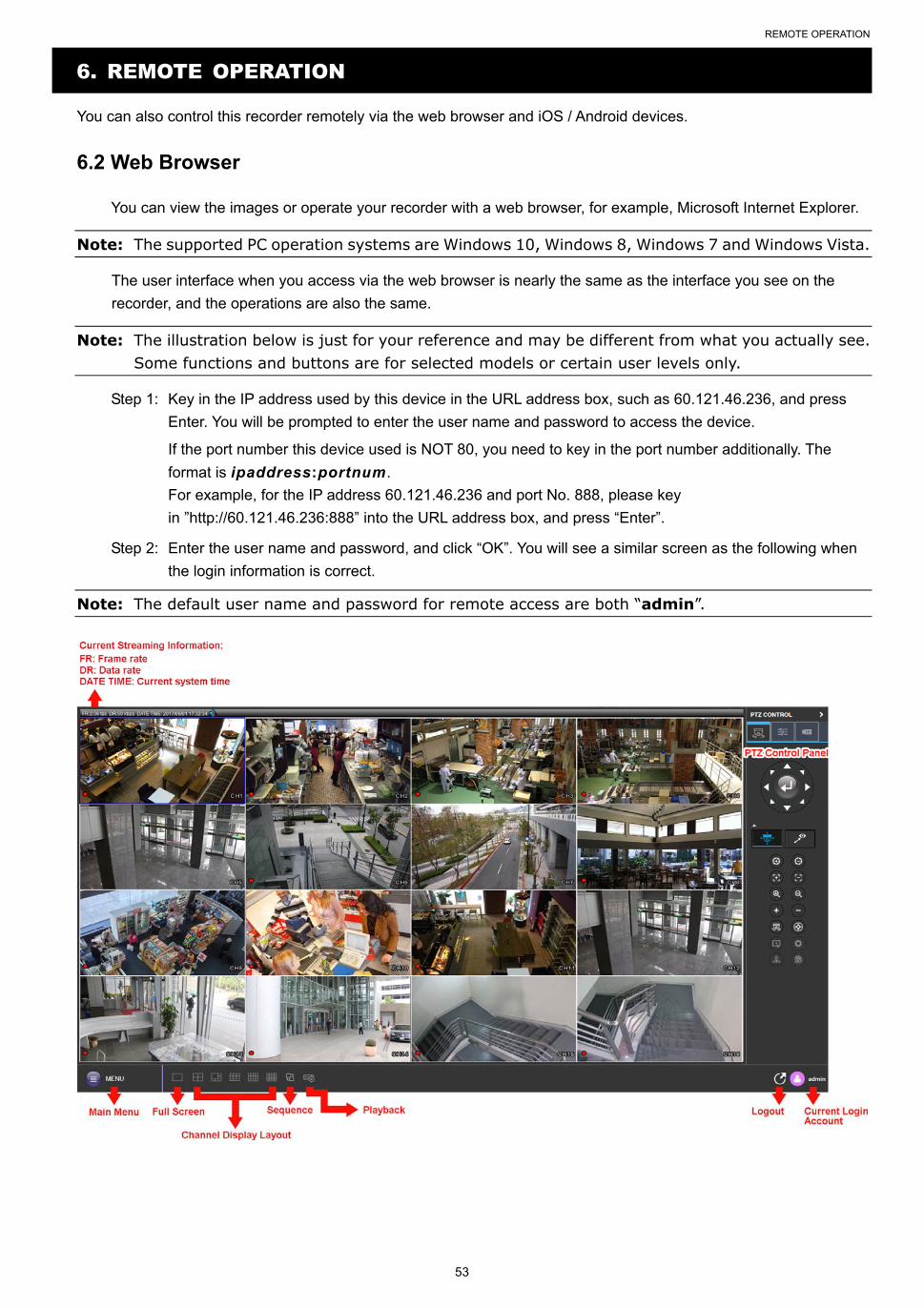
REMOTE OPERATION
53
6. REMOTE OPERATION
You can also control this recorder remotely via the web browser and iOS / Android devices.
6.2 Web Browser
You can view the images or operate your recorder with a web browser, for example, Microsoft Internet Explorer.
Note: The supported PC operation systems are Windows 10, Windows 8, Windows 7 and Windows Vista.
The user interface when you access via the web browser is nearly the same as the interface you see on the
recorder, and the operations are also the same.
Note: The illustration below is just for your reference and may be different from what you actually see. Some functions and buttons are for selected models or certain user levels only.
Step 1: Key in the IP address used by this device in the URL address box, such as 60.121.46.236, and press
Enter. You will be prompted to enter the user name and password to access the device.
If the port number this device used is NOT 80, you need to key in the port number additionally. The
format is ipaddress:portnum.
For example, for the IP address 60.121.46.236 and port No. 888, please key
in ”http://60.121.46.236:888” into the URL address box, and press “Enter”.
Step 2: Enter the user name and password, and click “OK”. You will see a similar screen as the following when
the login information is correct.
Note: The default user name and password for remote access are both “admin”.
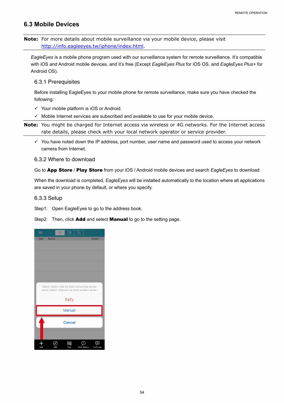
REMOTE OPERATION
54
6.3 Mobile Devices
Note: For more details about mobile surveillance via your mobile device, please visit http://info.eagleeyes.tw/iphone/index.html.
EagleEyes is a mobile phone program used with our surveillance system for remote surveillance. It’s compatible
with iOS and Android mobile devices, and it’s free (Except EagleEyes Plus for iOS OS, and EagleEyes Plus+ for
Android OS).
6.3.1 Prerequisites
Before installing EagleEyes to your mobile phone for remote surveillance, make sure you have checked the
following:
Your mobile platform is iOS or Android.
Mobile Internet services are subscribed and available to use for your mobile device.
Note: You might be charged for Internet access via wireless or 4G networks. For the Internet access rate details, please check with your local network operator or service provider.
You have noted down the IP address, port number, user name and password used to access your network
camera from Internet.
6.3.2 Where to download
Go to App Store / Play Store from your iOS / Android mobile devices and search EagleEyes to download.
When the download is completed, EagleEyes will be installed automatically to the location where all applications
are saved in your phone by default, or where you specify.
6.3.3 Setup
Step1: Open EagleEyes to go to the address book.
Step2: Then, click Add and select Manual to go to the setting page.

REMOTE OPERATION
55
Step3: In the setting page, enter all the information needed to access this device in the REQUIRED column,
and click Get Type to examine if the information you entered is correct. The device type will be
detected properly.
Step4: (Optional) Configure the settings in the OPTIONAL column as needed.
Step5: Click Save to return to the address book. Enable Guard to receive Push Video.
Step6: Click on the item you just added in the address book to access and check the live view.

APPENDIX 1 PRODUCT SPECIFICATIONS
56
APPENDIX 1 PRODUCT SPECIFICATIONS
Model 1 Model 2
Hardware
Video Input One LAN port (up to 16 IP cameras)
Video Output HDMI x 2 / VGA x 1 HDMI x 2 / VGA x 1 / Composite x 1
Video Output Resolution HDMI-1: Up to 3840 x 2160 (4K2K)
HDMI-2 & VGA: Up to 1920 x 1080 (Full HD)
Audio Output YES (Line out / HDMI)
Audio Input YES (Mic in)
Alarm I/O 4 in / 1 out Alarm out only
HDD Storage** Five 6TB hard disks Eight 6TB hard disks
eSATA Port YES NO
RS485 Port YES NO
USB Ports USB 3.0 x 1 / USB 2.0 x 2
IR Remote Control YES
Ethernet LAN port 1000Mbps
Internet (WAN) port 1000Mbps
Software
Video Compression Format H.265
Audio Compression Format G.711
Local / Remote Display Mode 16CH
Local / Remote Playback Mode 16CH
Single Channel Playback YES
Record Stream Dual
Recording Mode Manual / Event / Alarm / Schedule
Recording Throughput Up to 480 IPS @ 2592 x 1944 (5MP), Up to 300Mbps
Pre-alarm Recording YES
Quick Search Time / Event
Event Notification Push Video / Push Status / Video Mail / Message Mail
Security Multiple user access levels with password
Remote Access (1) Internet Explorer on Windows operating system
(2) EagleEyes on iOS & Android mobile devices (3) Our self-developed program, Video Viewer
Max. Online User 20
Multicast YES
Seamless Recording YES
Smart Search YES
Spot Monitor Setup Call Monitor / Event Monitor / Live Monitor (HDMI-2 only)
Alarm Scenario Setup YES
Alarm Pop-up & Preview YES
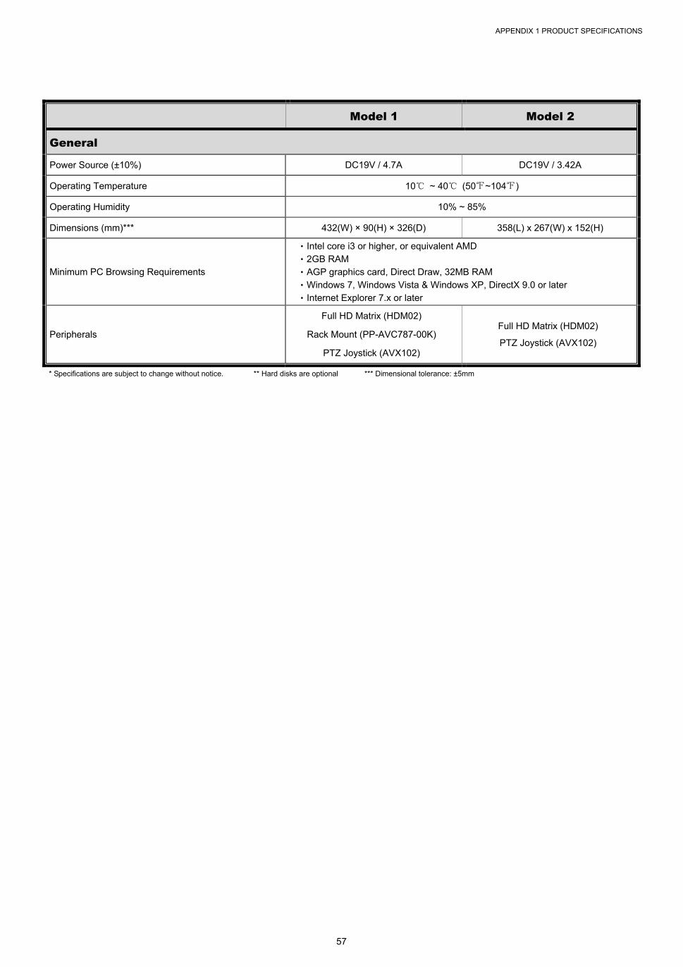
APPENDIX 1 PRODUCT SPECIFICATIONS
57
Model 1 Model 2
General
Power Source (±10%) DC19V / 4.7A DC19V / 3.42A
Operating Temperature 10℃ ~ 40℃ (50℉~104℉)
Operating Humidity 10% ~ 85%
Dimensions (mm)*** 432(W) × 90(H) × 326(D) 358(L) x 267(W) x 152(H)
Minimum PC Browsing Requirements
‧Intel core i3 or higher, or equivalent AMD ‧2GB RAM ‧AGP graphics card, Direct Draw, 32MB RAM ‧Windows 7, Windows Vista & Windows XP, DirectX 9.0 or later ‧Internet Explorer 7.x or later
Peripherals
Full HD Matrix (HDM02)
Rack Mount (PP-AVC787-00K)
PTZ Joystick (AVX102)
Full HD Matrix (HDM02)
PTZ Joystick (AVX102)
* Specifications are subject to change without notice. ** Hard disks are optional *** Dimensional tolerance: ±5mm
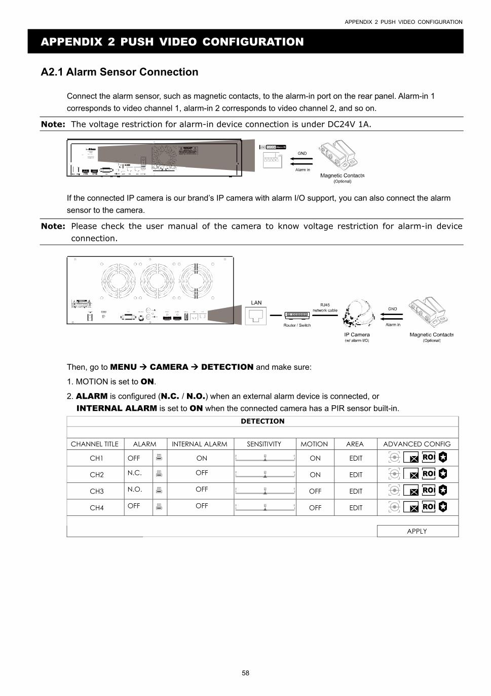
APPENDIX 2 PUSH VIDEO CONFIGURATION
58
APPENDIX 2 PUSH VIDEO CONFIGURATION
A2.1 Alarm Sensor Connection
Connect the alarm sensor, such as magnetic contacts, to the alarm-in port on the rear panel. Alarm-in 1
corresponds to video channel 1, alarm-in 2 corresponds to video channel 2, and so on.
Note: The voltage restriction for alarm-in device connection is under DC24V 1A.
If the connected IP camera is our brand’s IP camera with alarm I/O support, you can also connect the alarm
sensor to the camera.
Note: Please check the user manual of the camera to know voltage restriction for alarm-in device connection.
Then, go to MENU CAMERA DETECTION and make sure:
1. MOTION is set to ON.
2. ALARM is configured (N.C. / N.O.) when an external alarm device is connected, or
INTERNAL ALARM is set to ON when the connected camera has a PIR sensor built-in.
DETECTION CHANNEL TITLE ALARM INTERNAL ALARM SENSITIVITY MOTION AREA ADVANCED CONFIG
CH1 OFF ON ON EDIT
CH2 N.C. OFF ON EDIT
CH3 N.O. OFF OFF EDIT
CH4 OFF OFF OFF EDIT
APPLY
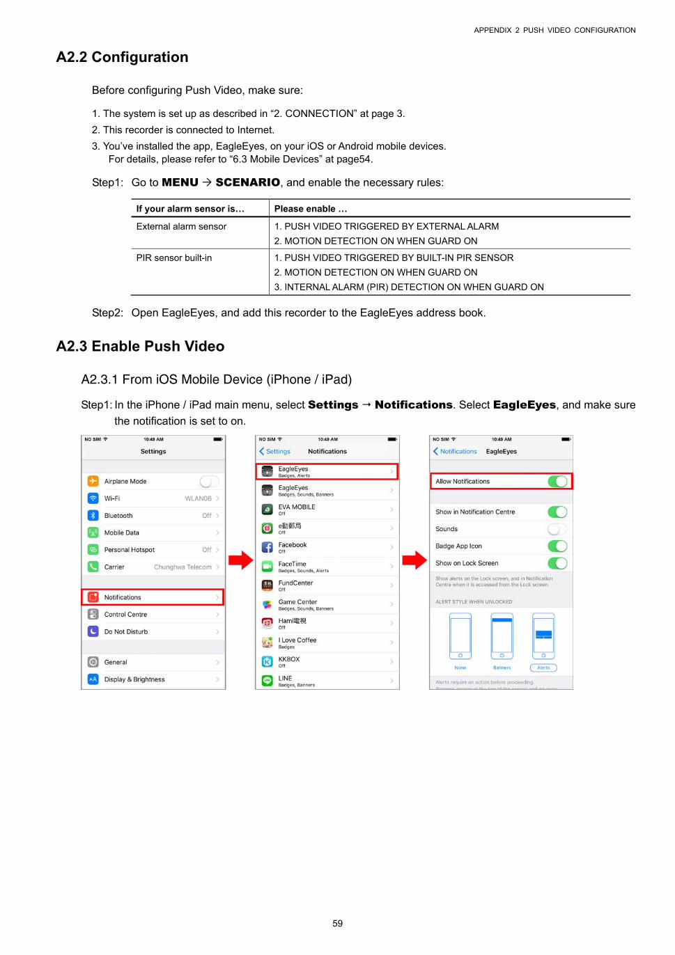
APPENDIX 2 PUSH VIDEO CONFIGURATION
59
A2.2 Configuration
Before configuring Push Video, make sure:
1. The system is set up as described in “2. CONNECTION” at page 3.
2. This recorder is connected to Internet.
3. You’ve installed the app, EagleEyes, on your iOS or Android mobile devices. For details, please refer to “6.3 Mobile Devices” at page54.
Step1: Go to MENU SCENARIO, and enable the necessary rules:
If your alarm sensor is… Please enable …
External alarm sensor 1. PUSH VIDEO TRIGGERED BY EXTERNAL ALARM
2. MOTION DETECTION ON WHEN GUARD ON
PIR sensor built-in 1. PUSH VIDEO TRIGGERED BY BUILT-IN PIR SENSOR
2. MOTION DETECTION ON WHEN GUARD ON
3. INTERNAL ALARM (PIR) DETECTION ON WHEN GUARD ON
Step2: Open EagleEyes, and add this recorder to the EagleEyes address book.
A2.3 Enable Push Video
A2.3.1 From iOS Mobile Device (iPhone / iPad)
Step1: In the iPhone / iPad main menu, select Settings Notifications. Select EagleEyes, and make sure
the notification is set to on.
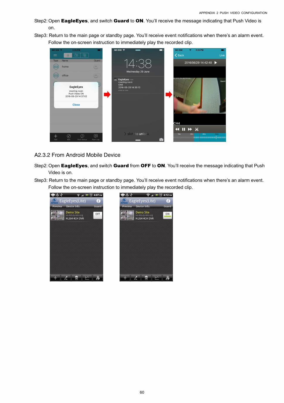
APPENDIX 2 PUSH VIDEO CONFIGURATION
60
Step2: Open EagleEyes, and switch Guard to ON. You’ll receive the message indicating that Push Video is
on.
Step3: Return to the main page or standby page. You’ll receive event notifications when there’s an alarm event.
Follow the on-screen instruction to immediately play the recorded clip.
A2.3.2 From Android Mobile Device
Step2: Open EagleEyes, and switch Guard from OFF to ON. You’ll receive the message indicating that Push
Video is on.
Step3: Return to the main page or standby page. You’ll receive event notifications when there’s an alarm event.
Follow the on-screen instruction to immediately play the recorded clip.

APPENDIX 3 COMPATIBLE USB FLASH DRIVE LIST
61
APPENDIX 3 COMPATIBLE USB FLASH DRIVE LIST
Please upgrade the firmware of the recorder to the latest version to ensure the accuracy of the following table. If the
USB flash drive is not supported by the recorder, you will see on the screen.
Note: Please use your PC to format the USB flash drive as “FAT32”.
Note: You can backup up to 2GB video data for one-time USB backup. To backup more data, please set the time & channel(s) you want, and start USB backup again.
MANUFACTURER MODEL CAPACITY
Transcend JFV35 4GB
JFV30 8GB
Kingston DataTraveler 1GB
PQI U172P 4GB
Apacer AH320 2GB
AH320A 8GB
AH220 1GB
AH320 4GB
A-data RB-18 1GB
Sandisk Cruzer Micro 2GB
Cruzer Micro 4GB
Cruzer4-pk 2GB
Netac U208 1GB
MSI F200 4GB
SONY Micro Vault Tiny 2GB 2GB
Micro Vault Tiny 4GB 4GB
Micro Vault Tiny 1GB

APPENDIX 4 COMPATIBLE HARD DISK LIST
62
APPENDIX 4 COMPATIBLE HARD DISK LIST
Please upgrade the firmware of the device to the latest version to ensure the accuracy of the following table.
Note: It’s necessary to install a hard disk first before firmware upgrade to ensure the upgrade process works properly.
Note: To use a green hard disk, use ONLY the hard disk designed especially for surveillance to ensure the device works properly.
Seagate*
MODEL CAPACITY MODEL CAPACITYPipeline HD
ST3500312CSS 500GB ST3000VX004 3TB
Pipeline HD ST500VT000
500GB ST3000VX005 3TB Pipeline HD
ST1000VM002 1TB ST3000VX006 3TB
Pipeline HD ST1000VM002
1TB ST3000VX000 3TB
ST31000525SV 1TB ST4000VM000 4TB
ST31000340AS 1TB ST4000VX000 4TB
ST1000VX000 1TB ST4000VX002 4TB
ST1000VX002 1TB ST4000VX007 4TB
ST1000VX001 1TB ST6000VX0001 6TB**
ST1000VX005 1TB ST6000VX0011 6TB**
ST2000VX000 2TB ST6000NM0024 6TB**
ST2000DM001 2TB ST8000VX002 8TB**
ST2000VX004 2TB ST8000VX0022 8TB**
ST3000VM002 3TB ST100000VX0004 10TB**
WD
MODEL CAPACITY MODEL CAPACITY
WD10PURX 1TB WD30EFRX 3TB
WD20PURX 2TB WD40PURX 4TB
WD20EURS 2TB WD40EURX 4TB
WD20EURX 2TB WD60EURX 6TB**
WD20EFRX 2TB WD60PURX 6TB**
WD2002FAEX 2TB WD6001FFWX 6TB**
WD30PURX 3TB WD6001FSYZ 6TB**
WD30EURX 3TB
TOSHIBA
MODEL CAPACITY MODEL CAPACITY
DT01ACA050 500GB MD03ACA200V 2TB
DT01ABA050V 500GB DT01ABA300V 3TB
DT01ACA100 1TB DT01ACA300 3TB
DT01ABA100V 1TB MD03ACA300V 3TB
DT01ACA200 2TB MD03ACA400V 4TB
DT01ABA200V 2TB MD04ABA500V 5TB
* To know more details about SRS and its related support and service, please contact your local Seagate representative directly. ** Please be advised to pay attention to the heat dissipation of the hard disk which is over 4TB because it might generate much heat
during operation. It’s recommended that ambient temperature is not over 35°C.

APPENDIX 5 BATTERY REPLACEMENT
63
APPENDIX 5 BATTERY REPLACEMENT
The time reset after power failure, for example, caused by a power outage, will cause the disorder of the recorded
data, and users may have problems in searching the event clip they want. To keep the device time from resetting, a
non-chargeable lithium battery, CR2032, is installed in the device.
However, the device time might still get reset when the battery is low or even running out of power. If so, please
replace the device battery, CR2032, right away as instructed below.
How to replace CR2032
Note: The lithium battery, CR2032, is a non-chargeable battery, and should be purchased separately. Please replace only with the same or equivalent type battery in case of danger.
Step1: Stop all recording immediately to prevent the disorder of the recorded data. Then, back up the recorded data
if necessary.
Step2: Power off the device, and disconnect the power.
Step3: Remove the device upper cover or rear panel to find the battery on the mainboard.
Step4: Push the release as indicated below to remove the battery.
Step5: Get a new battery and install it to its slot on the main board.
For Type 1, install it with the side of “CR2032” facing up as shown above.
For Type 2, install it without the side of “CR2032” facing you as shown above.
Step6: Replace the cover and connect to power.
Step7: Set the date & time, and resume recording.

APPENDIX 6 DISK ARRAY COMPATIBLE LIST
64
APPENDIX 6 DISK ARRAY COMPATIBLE LIST
Here's the compatible list for disk arrays.
Note: For the compatible hard disks used for those disk arrays listed below, please check their respective user manuals or official websites.
Brand Model Number
Proware EP-D501-AA
EP-2123-UA-R
RAIDON GT1650-SB3
GR3630-SB3
STARDOM DR5-WBS3
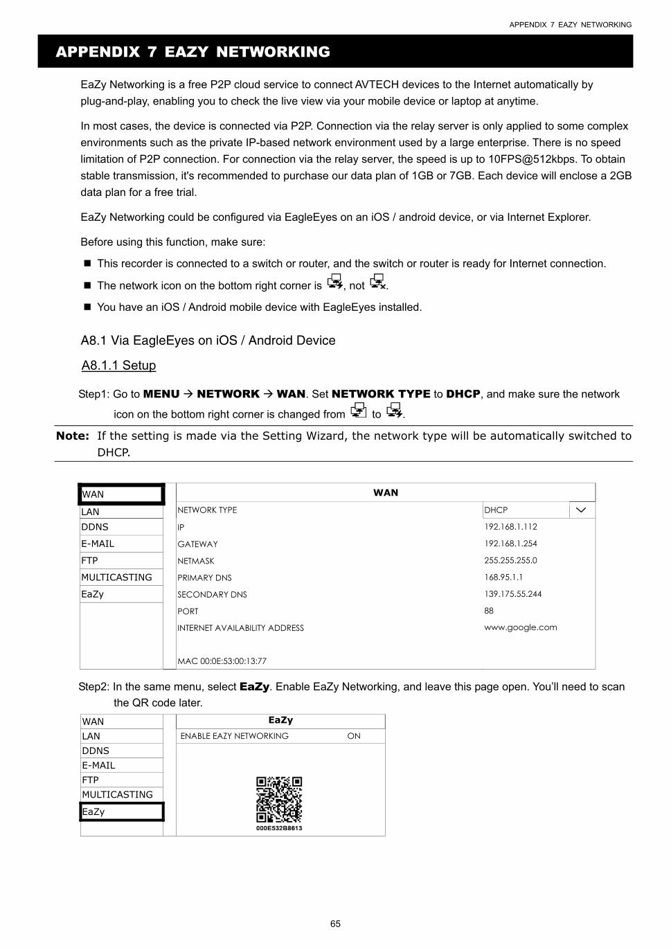
APPENDIX 7 EAZY NETWORKING
65
APPENDIX 7 EAZY NETWORKING
EaZy Networking is a free P2P cloud service to connect AVTECH devices to the Internet automatically by
plug-and-play, enabling you to check the live view via your mobile device or laptop at anytime.
In most cases, the device is connected via P2P. Connection via the relay server is only applied to some complex
environments such as the private IP-based network environment used by a large enterprise. There is no speed
limitation of P2P connection. For connection via the relay server, the speed is up to 10FPS@512kbps. To obtain
stable transmission, it's recommended to purchase our data plan of 1GB or 7GB. Each device will enclose a 2GB
data plan for a free trial.
EaZy Networking could be configured via EagleEyes on an iOS / android device, or via Internet Explorer.
Before using this function, make sure:
This recorder is connected to a switch or router, and the switch or router is ready for Internet connection.
The network icon on the bottom right corner is , not .
You have an iOS / Android mobile device with EagleEyes installed.
A8.1 Via EagleEyes on iOS / Android Device
A8.1.1 Setup
Step1: Go to MENU NETWORK WAN. Set NETWORK TYPE to DHCP, and make sure the network
icon on the bottom right corner is changed from to .
Note: If the setting is made via the Setting Wizard, the network type will be automatically switched to DHCP.
WAN WAN
LAN NETWORK TYPE DHCP
DDNS IP 192.168.1.112
E-MAIL GATEWAY 192.168.1.254
FTP NETMASK 255.255.255.0
MULTICASTING PRIMARY DNS 168.95.1.1
EaZy SECONDARY DNS 139.175.55.244
PORT 88
INTERNET AVAILABILITY ADDRESS www.google.com
MAC 00:0E:53:00:13:77
Step2: In the same menu, select EaZy. Enable EaZy Networking, and leave this page open. You’ll need to scan
the QR code later.
WAN EaZy
LAN ENABLE EAZY NETWORKING ON
DDNS
E-MAIL FTP MULTICASTING
EaZy

APPENDIX 7 EAZY NETWORKING
66
Step3: Open EagleEyes on your mobile device, and select “…” on the top left corner in the address book. Then,
click “EaZy”.
Step4: Click “Login” and register an account for “Cloud Service”. If you’ve got an account, please just log in.
Step5: Go back to the address book and click “+” (Add) to add a new device.
There are two methods to add new devices, “EaZy” and “Manual”.
Select “EaZy”, and choose the recorder icon to continue.
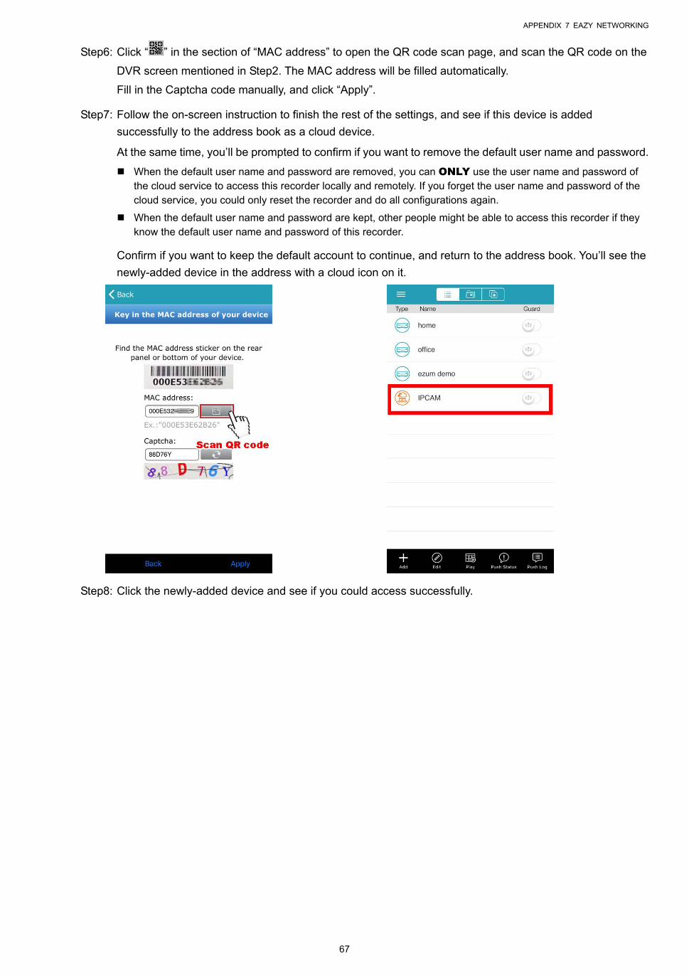
APPENDIX 7 EAZY NETWORKING
67
Step6: Click “ ” in the section of “MAC address” to open the QR code scan page, and scan the QR code on the
DVR screen mentioned in Step2. The MAC address will be filled automatically.
Fill in the Captcha code manually, and click “Apply”.
Step7: Follow the on-screen instruction to finish the rest of the settings, and see if this device is added
successfully to the address book as a cloud device.
At the same time, you’ll be prompted to confirm if you want to remove the default user name and password.
When the default user name and password are removed, you can ONLY use the user name and password of the cloud service to access this recorder locally and remotely. If you forget the user name and password of the cloud service, you could only reset the recorder and do all configurations again.
When the default user name and password are kept, other people might be able to access this recorder if they know the default user name and password of this recorder.
Confirm if you want to keep the default account to continue, and return to the address book. You’ll see the
newly-added device in the address with a cloud icon on it.
Step8: Click the newly-added device and see if you could access successfully.
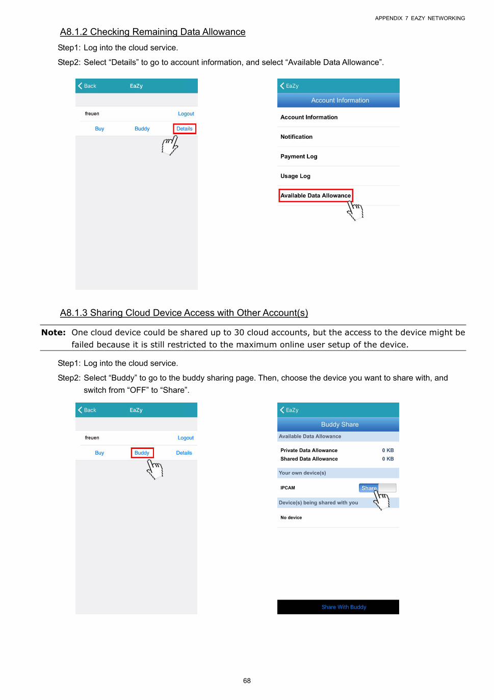
APPENDIX 7 EAZY NETWORKING
68
A8.1.2 Checking Remaining Data Allowance
Step1: Log into the cloud service.
Step2: Select “Details” to go to account information, and select “Available Data Allowance”.
A8.1.3 Sharing Cloud Device Access with Other Account(s)
Note: One cloud device could be shared up to 30 cloud accounts, but the access to the device might be failed because it is still restricted to the maximum online user setup of the device.
Step1: Log into the cloud service.
Step2: Select “Buddy” to go to the buddy sharing page. Then, choose the device you want to share with, and
switch from “OFF” to “Share”.
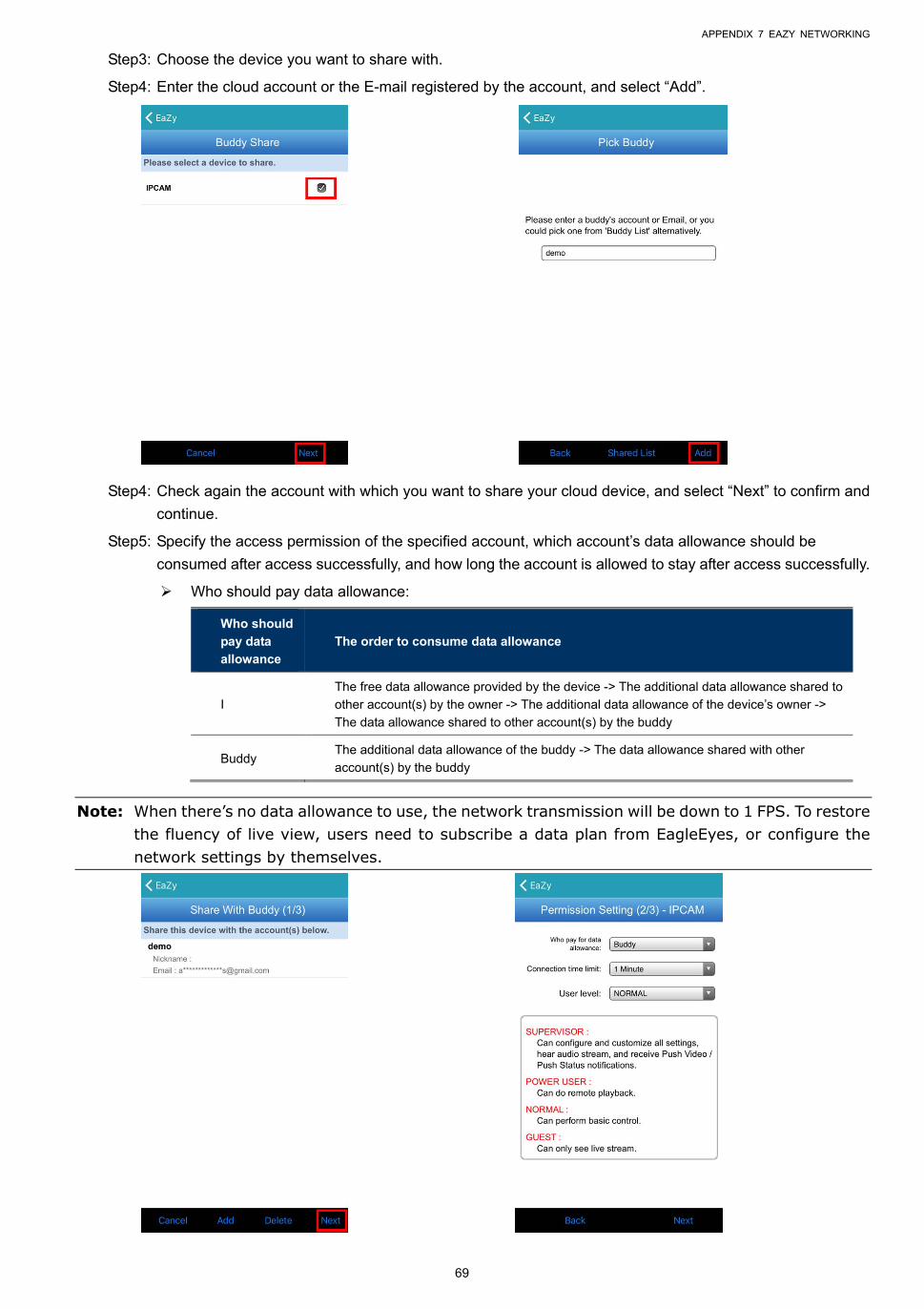
APPENDIX 7 EAZY NETWORKING
69
Step3: Choose the device you want to share with.
Step4: Enter the cloud account or the E-mail registered by the account, and select “Add”.
Step4: Check again the account with which you want to share your cloud device, and select “Next” to confirm and
continue.
Step5: Specify the access permission of the specified account, which account’s data allowance should be
consumed after access successfully, and how long the account is allowed to stay after access successfully.
Who should pay data allowance:
Who should
pay data
allowance
The order to consume data allowance
I
The free data allowance provided by the device -> The additional data allowance shared to
other account(s) by the owner -> The additional data allowance of the device’s owner ->
The data allowance shared to other account(s) by the buddy
Buddy The additional data allowance of the buddy -> The data allowance shared with other
account(s) by the buddy
Note: When there’s no data allowance to use, the network transmission will be down to 1 FPS. To restore
the fluency of live view, users need to subscribe a data plan from EagleEyes, or configure the network settings by themselves.
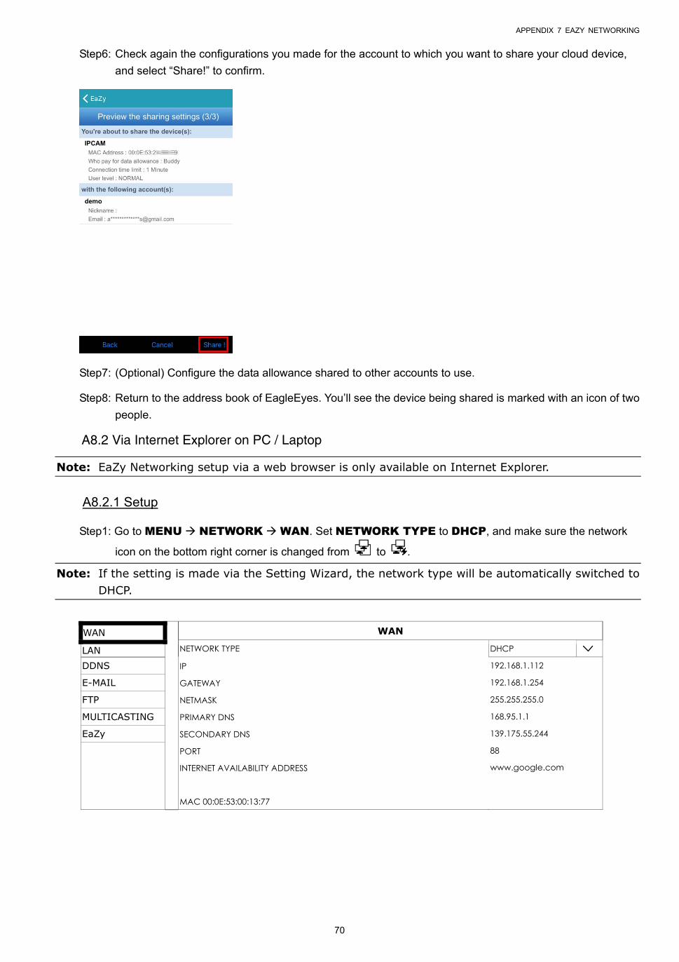
APPENDIX 7 EAZY NETWORKING
70
Step6: Check again the configurations you made for the account to which you want to share your cloud device,
and select “Share!” to confirm.
Step7: (Optional) Configure the data allowance shared to other accounts to use.
Step8: Return to the address book of EagleEyes. You’ll see the device being shared is marked with an icon of two
people.
A8.2 Via Internet Explorer on PC / Laptop
Note: EaZy Networking setup via a web browser is only available on Internet Explorer.
A8.2.1 Setup
Step1: Go to MENU NETWORK WAN. Set NETWORK TYPE to DHCP, and make sure the network
icon on the bottom right corner is changed from to .
Note: If the setting is made via the Setting Wizard, the network type will be automatically switched to DHCP.
WAN WAN
LAN NETWORK TYPE DHCP
DDNS IP 192.168.1.112
E-MAIL GATEWAY 192.168.1.254
FTP NETMASK 255.255.255.0
MULTICASTING PRIMARY DNS 168.95.1.1
EaZy SECONDARY DNS 139.175.55.244
PORT 88
INTERNET AVAILABILITY ADDRESS www.google.com
MAC 00:0E:53:00:13:77
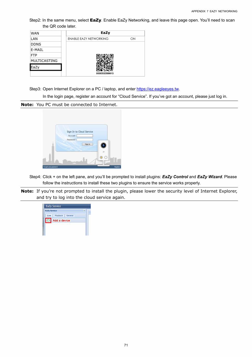
APPENDIX 7 EAZY NETWORKING
71
Step2: In the same menu, select EaZy. Enable EaZy Networking, and leave this page open. You’ll need to scan
the QR code later.
WAN EaZy
LAN ENABLE EAZY NETWORKING ON
DDNS
E-MAIL FTP MULTICASTING
EaZy
Step3: Open Internet Explorer on a PC / laptop, and enter https://ez.eagleeyes.tw.
In the login page, register an account for “Cloud Service”. If you’ve got an account, please just log in.
Note: You PC must be connected to Internet.
Step4: Click + on the left pane, and you’ll be prompted to install plugins: EaZy Control and EaZy Wizard. Please
follow the instructions to install these two plugins to ensure the service works properly.
Note: If you’re not prompted to install the plugin, please lower the security level of Internet Explorer, and try to log into the cloud service again.
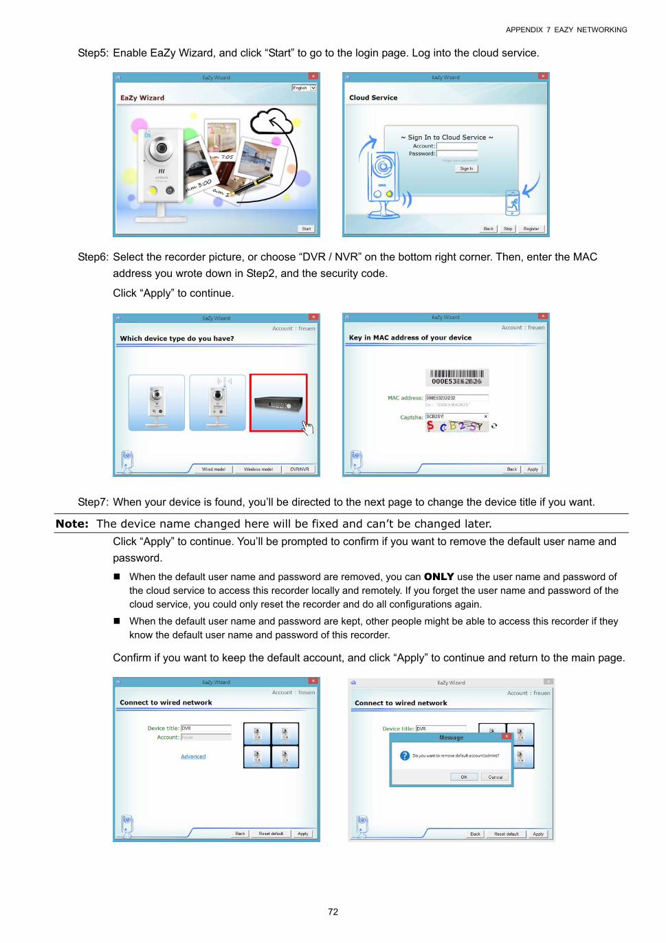
APPENDIX 7 EAZY NETWORKING
72
Step5: Enable EaZy Wizard, and click “Start” to go to the login page. Log into the cloud service.
Step6: Select the recorder picture, or choose “DVR / NVR” on the bottom right corner. Then, enter the MAC
address you wrote down in Step2, and the security code.
Click “Apply” to continue.
Step7: When your device is found, you’ll be directed to the next page to change the device title if you want.
Note: The device name changed here will be fixed and can’t be changed later. Click “Apply” to continue. You’ll be prompted to confirm if you want to remove the default user name and
password.
When the default user name and password are removed, you can ONLY use the user name and password of the cloud service to access this recorder locally and remotely. If you forget the user name and password of the cloud service, you could only reset the recorder and do all configurations again.
When the default user name and password are kept, other people might be able to access this recorder if they know the default user name and password of this recorder.
Confirm if you want to keep the default account, and click “Apply” to continue and return to the main page.
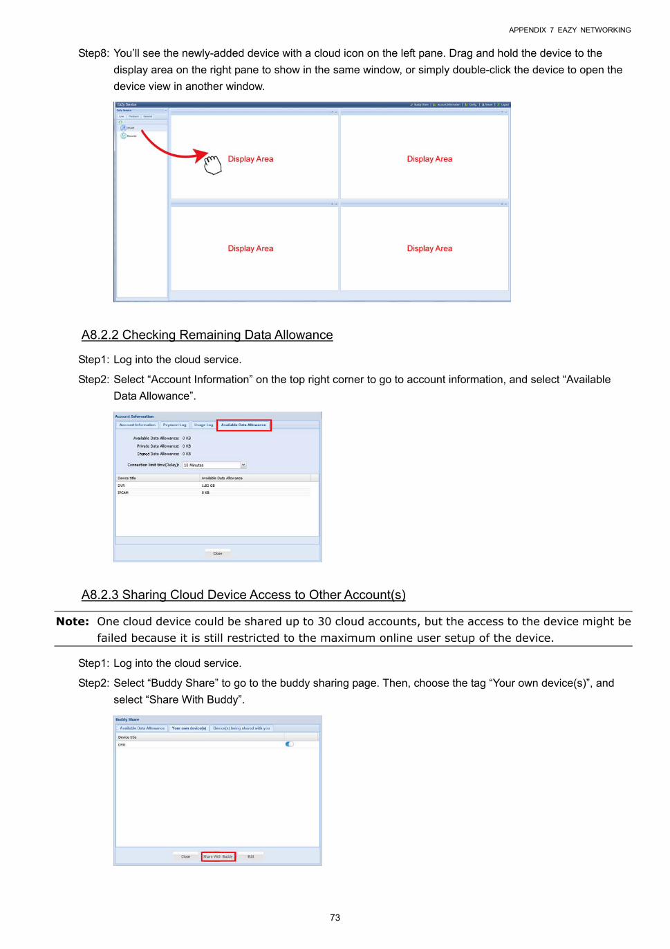
APPENDIX 7 EAZY NETWORKING
73
Step8: You’ll see the newly-added device with a cloud icon on the left pane. Drag and hold the device to the
display area on the right pane to show in the same window, or simply double-click the device to open the
device view in another window.
A8.2.2 Checking Remaining Data Allowance
Step1: Log into the cloud service.
Step2: Select “Account Information” on the top right corner to go to account information, and select “Available
Data Allowance”.
A8.2.3 Sharing Cloud Device Access to Other Account(s)
Note: One cloud device could be shared up to 30 cloud accounts, but the access to the device might be failed because it is still restricted to the maximum online user setup of the device.
Step1: Log into the cloud service.
Step2: Select “Buddy Share” to go to the buddy sharing page. Then, choose the tag “Your own device(s)”, and
select “Share With Buddy”.
APPENDIX 7 EAZY NETWORKING
74
Step3: Choose the cloud device you want to share, and click “Next” to enter the cloud account or the E-mail
registered by the account you want to share with. Then, select “Add”.
Step4: Check again the account to which you want to share your cloud device.
To add more accounts, select “Add”; to remove the existing account, select “Delete”; to continue buddy
setup, select “Next”.
Step5: Specify the access permission of the specified account, which account’s data allowance should be
consumed after access successfully, and how long the account is allowed to stay after access successfully.
Who should pay data allowance:
Who should
pay data
allowance
The order to consume data allowance
I
The free data allowance provided by the device -> The additional data allowance shared to
other account(s) by the owner -> The additional data allowance of the device’s owner ->
The data allowance shared to other account(s) by the buddy
Buddy The additional data allowance of the buddy -> The data allowance shared with other
account(s) by the buddy
Note: When there’s no data allowance to use, the network transmission will be down to 1 FPS. To restore the fluency of live view, users need to subscribe a data plan from EagleEyes, or configure the network settings by themselves.
Step6: Check again the configurations you made for the account to which you want to share your cloud device,
and select “Share!” to continue.
Step7: (Optional) Configure the data allowance shared to other accounts to use.
APPENDIX 7 EAZY NETWORKING
75
Step8: Return to the main page. You’ll see the device being shared is marked with an icon of two people.
A8.3 Icons
Icon Color Indication
Teal This device is a DVR or NVR.
Blue This device is a DVR or NVR.
Orange This device is an IP speed dome camera.
Red This device is disconnected and unidentified.
or
Depending on the device color
This device is configured to the Internet via EaZy Networking (AVTECH Cloud Service).
The cloud icon will be grayed out if the EaZy server can’t be connected.
Depending on the device color
You’ve shared the access right of the device with other cloud account via Buddy (AVTECH Cloud Service).
The icon will be grayed out if you disable the device share.
Depending on the device color
The icon will be grayed out if the device share is disabled by the owner of the device.
For example, if you see as the device type, you’ll know:
- This device is an IP camera.
- This device is connected to the Internet via EaZy Networking.
- You were shared with the access right of the device, but the device share is disabled now.