74HC165-Q100; 74HCT165-Q100 8-bit parallel-in/serial out ...
Upload
duonghuongCategory
view
218download
2
Automotive AEC-Q100 Grade 2 Compliance
Reliability Qualification Report
for
SDR SDRAM with Pb/Halogen Free
(4M×16, 63nm SDRAM AS4C4M16SA-6TAN/6BAN)
Issued Date: Dec 15, 2014
NOTE: THIS DOCUMENT MAY CONTAIN PROPRIETARY INFORMATION AND CANNOT BE DISCLOSED WITHOUT THE WRITTEN CONSENT OF ALLIANCE MEMORY INC.
1
CONTENTS
0. RELIABILITY TEST SUMMARY…………….……………...…..…………….…..1
1. INTRODUCTION ............................................................................................2
2. PRODUCT INFORMATION............................................................................2
3. RELIABILITY ..................................................................................................2
3.1. Sample Preparation Flow......................................................................2
3.2. Life Test ................................................................................................3
3.2.1. Test Flow...................................................................................3
3.2.2. Test Criteria...............................................................................3
3.2.3. Failure Rate Calculation and Test Result ..................................4
3.3. Environmental Test...............................................................................6
3.3.1. Test Flow...................................................................................7
3.3.2. Test Condition and Time ...........................................................7
3.3.3. Test Criteria and Result...........................................................10
3.4. ESD Test.............................................................................................11
3.5. Latch-Up Test......................................................................................11
4. CONCLUSION ..............................................................................................12
NOTE: THIS DOCUMENT MAY CONTAIN PROPRIETARY INFORMATION AND CANNOT BE DISCLOSED WITHOUT THE WRITTEN CONSENT OF ALLIANCE MEMORY INC.
2

Automotive AEC-Q100 Grade 2 Compliance Reliability Qualification Report for
AS4C4M16SA-6TAN/6BAN (4M x 16 SDR SDRAM with Pb/Halogen Free)
0. RELIABILITY TEST SUMMARY
Test Item Test Condition Pass Criteria Test Result
0 - 1 (Year) 0/800 x 3 EFR 1.2*Vint, 125°C, 48Hrs
≦1000 (DPM) 0 DPM (PASS)
1 - 10 (Year) 0/77 x 3
22 FIT (PASS) OLT 1.1*Vint, 125°C, 1000Hrs
≦50 (FIT) MTBF=
45 x 106 Hrs
MSLT Level III 0/1 (A/R) 0/231 x 3 (PASS)
HTST 150,
1000Hrs 0/1 (A/R) 0/45 x 1 (PASS)
TCT -65 ~ +150, @3cph,
500Cycles 0/1 (A/R) 0/77 x 3 (PASS)
PCT
121, 100%R.H., 2.0atm, 168Hrs for TSOP
96Hrs for BGA 0/1 (A/R) 0/77 x 3 (PASS)
HAST 130, 85%R.H.,
2.3atm, 3.6V, 96Hrs 0/1 (A/R) 0/77 x 3 (PASS)
HBM: R=1.5KΩ, C=100pF ≧±2KV 0/3 x 1 (PASS)
MM: R=0KΩ, C=200pF ≧±200V 0/3 x 1 (PASS) ESD CDM: Non-Socket Mode ≧±1KV 0/3 x 1 (PASS)
Latch-Up
Vtr(+)≧1.5 * Vcc Vtr(-)≦-0.5 * Vcc
Itr(+)≧100mA Itr(-)≦-100mA
0/6 x 1 (PASS)
Moisture Sensitivity Level Test Flow & Condition: Electrical Test SAT TC (-65~+150, 5Cycles) Bake (125, 24Hrs) Soak Level III (30, 60%R.H., 192Hrs) Convection Reflow (260 +5/-0, 0~20Secs, 3Cycles) Electrical Test SAT
NOTE: THIS DOCUMENT MAY CONTAIN PROPRIETARY INFORMATION AND CANNOT BE DISCLOSED WITHOUT THE WRITTEN CONSENT OF ALLIANCE MEMORY INC.
3

1. INTRODUCTION
In order to meet the most stringent market demands for high quality and
reli-ability semiconductor components, Alliance Memory maintains a strict
reliability program in all products. The purpose of this report is to give an
overview of the reliability status of AS4C4M16SA-6TAN/6BAN. Accelerated
tests are performed on product, and then the results are extrapolated to
standard operating conditions in order to calculate and estimate the
component’s failure rate.
2. PRODUCT INFORMATION
The AS4C4M16SA-6TAN/6BAN is a 4M*16 bits high-speed CMOS Single
Data Rate Syn-chronous Dynamic Random Access Memory (SDR SDRAM)
operating from a sin-gle 3.0 to 3.6 Volt power supply. By employing some new
CMOS circuit design technologies and the advanced DRAM process
technologies, the AS4C4M16SA-6TAN/6BAN is well suited forapplications requiring high memory bandwidth and particularly well suited to
high performance PC applications.
The AS4C4M16SA-6TAN/6BAN is packaged in a standard 54pin, plastic
400mil TSOPII or a standard 60ball, plastic 6.4x10.1mm BGA or a standard
54ball, plastic 8x8mm BGA.
3. RELIABILITY
Many stress tests have been standardized in such documents as
JESD22 and AEC-Q100. From these standards, Alliance Memory has selected a series of tests to ensure that reliability targets are being met. These tests,
including life test, environmental test, ESD test and latch-up test, are discussed in
the following sections.
3.1. Sample Preparation Flow
CP Assembly 54L TSOP or 54/60B BGA FT Sampling Good Parts
for Reliability Test
NOTE: THIS DOCUMENT MAY CONTAIN PROPRIETARY INFORMATION AND CANNOT BE DISCLOSED WITHOUT THE WRITTEN CONSENT OF ALLIANCE MEMORY INC.
4
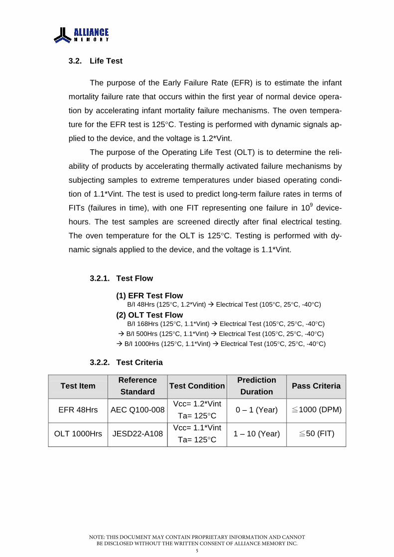
3.2. Life Test
The purpose of the Early Failure Rate (EFR) is to estimate the infant
mortality failure rate that occurs within the first year of normal device opera-
tion by accelerating infant mortality failure mechanisms. The oven tempera-
ture for the EFR test is 125°C. Testing is performed with dynamic signals ap-
plied to the device, and the voltage is 1.2*Vint.
The purpose of the Operating Life Test (OLT) is to determine the reli-
ability of products by accelerating thermally activated failure mechanisms by
subjecting samples to extreme temperatures under biased operating condi-
tion of 1.1*Vint. The test is used to predict long-term failure rates in terms of
FITs (failures in time), with one FIT representing one failure in 109 device-
hours. The test samples are screened directly after final electrical testing.
The oven temperature for the OLT is 125°C. Testing is performed with dy-
namic signals applied to the device, and the voltage is 1.1*Vint.
3.2.1. Test Flow
(1) EFR Test Flow B/I 48Hrs (125°C, 1.2*Vint) Electrical Test (105°C, 25°C, -40°C)
(2) OLT Test Flow B/I 168Hrs (125°C, 1.1*Vint) Electrical Test (105°C, 25°C, -40°C)
B/I 500Hrs (125°C, 1.1*Vint) Electrical Test (105°C, 25°C, -40°C)
B/I 1000Hrs (125°C, 1.1*Vint) Electrical Test (105°C, 25°C, -40°C)
3.2.2. Test Criteria
Test Item Reference Standard
Test Condition Prediction Duration
Pass Criteria
EFR 48Hrs AEC Q100-008 Vcc= 1.2*Vint
Ta= 125°C 0 – 1 (Year) ≦1000 (DPM)
OLT 1000Hrs JESD22-A108 Vcc= 1.1*Vint
Ta= 125°C 1 – 10 (Year) ≦50 (FIT)
NOTE: THIS DOCUMENT MAY CONTAIN PROPRIETARY INFORMATION AND CANNOT BE DISCLOSED WITHOUT THE WRITTEN CONSENT OF ALLIANCE MEMORY INC.
5

3.2.3. Failure Rate Calculation and Test Result
The life test is performed for the purpose of accelerating the
probable electrical and physical weakness of devices subjected to the
specified conditions over an extended time period.
By choosing the appropriate thermal activation energy (Ea), da-
ta taken at an elevated temperature can be translated to a lower stan-
dard operating temperature through the Arrhenius equation:
T(AF)= Exp [(Ea/k)*(1/Tn-1/Ts)]…(1)
where
T(AF)= Temperature Acceleration Factor
Tn= Normal Temperature in Absolute Temperature (K)
Ts= Stress Temperature in Absolute Temperature (K)
k= Boltzmann’s Constant (8.62*10^-5 eV/K)
Ea= Thermal Activation Energy
By choosing the appropriate electrical field acceleration rate con-
stant (Vf), data taken at an elevated voltage can be translated to a
lower standard operating voltage through the Eyring model:
E(AF)= Exp [Vf*(Vs-Vn)]…(2)
where
E(AF)= Electrical Field Acceleration Factor
Vn= Normal Operating Voltage
Vs= Stress Operating Voltage
Vf= Electrical Field Acceleration Rate Constant
By combining the equation (1) & (2), the failure rate (λ) can be
calculated by using the following equation:
λ(FIT)= [(Lamda of 60% CL) / (2*TDH*AF)]*10^9…(3)
where
λ= Failure Rate in FIT
NOTE: THIS DOCUMENT MAY CONTAIN PROPRIETARY INFORMATION AND CANNOT BE DISCLOSED WITHOUT THE WRITTEN CONSENT OF ALLIANCE MEMORY INC.
6

AF= Acceleration Factor
= T(AF) * E(AF)
TDH= Total Device-Hours of the Test
= Device No. * Hour
Lamda of CL= 60% Confidence Level (Refer to the Following Table)
DF Lamda 1 0.702 1.833 2.954 4.045 5.136 6.217 7.288 8.359 9.41
10 10.50DF= 2 * (Failure No. + 1)
Therefore, from equation (3), we can get the FIT number for our
OLT experiment. The MTBF can be also calculated from the reciprocal
of the FIT rate multiplied by 109.
3.2.3.1. EFR Test Result
A summary of Early Failure Rate (EFR) data for the
AS4C4M16SA-6TAN/6BAN is listed in Table 1, where the total
of 2,400 devices at 125°C has been collected with 0 failure.
Test Result (Failure / Sample Size) Test Item Sample
48 Hrs Failure Mode
EFR 2400ea 0/800 x 3 [= 0 DPM] N/A
Table 1. EFR Test Result for 0-1 Year Prediction
NOTE: THIS DOCUMENT MAY CONTAIN PROPRIETARY INFORMATION AND CANNOT BE DISCLOSED WITHOUT THE WRITTEN CONSENT OF ALLIANCE MEMORY INC.
7

3.2.3.2. OLT Test Result
A summary of Operating Life Test (OLT) data for
the AS4C4M16SA-6TAN/6BAN is listed in Table 2, where the
total of 231,000 device hours at 125°C has been collected
with 0 failure. We then use Ea= 0.5eV and Vf= 7.0(1/V) (a
worse case value from Alliance Memory‘s foundry) tocalculate the failure rate with a 60% confi-dence level. Table 3
shows the final result that the failure rate of 22 FIT at Ta = 55°C
and Vcc = 3.3V is predicted.
Test Result (Failure / Sample Size) Test Item Sample
168 Hrs 500 Hrs 1000 Hrs Failure Mode
OLT 231ea 0/77 x 3 0/77 x 3 0/77 x 3 N/A
Table 2. OLT Test Result
Failure Rate Prediction Device Total
(Ea= 0.5eV, Vf= 7.0(1/V)) Sample
-Hours Failure 55°C & 3.3V
(% / 1000hrs)
λ
(FIT)
MTBF (Hr)
231ea 231,000 0ea 0.0022 22 45 x 106
Table 3. OLT for 1-10 Year Failure Rate Prediction
3.3. Environmental Test
The purpose of environmental test is to evaluate the ability of semicon-
ductor device to withstand the temperature stress, humidity stress, electrical
stress or any combination of these. It can reveal not only the package quality
issue but also the possible error in wafer process or chip design interacting
with the assembly process.
NOTE: THIS DOCUMENT MAY CONTAIN PROPRIETARY INFORMATION AND CANNOT BE DISCLOSED WITHOUT THE WRITTEN CONSENT OF ALLIANCE MEMORY INC.
8

3.3.1. Test Flow
3.3.2. Test Condition and Time
3.3.2.1. Moisture Sensitivity Test
The purpose of moisture sensitivity test is to identify
the classification level of nonhermetic solid state Surface Mount
Devices (SMDs) that are sensitive to moisture induced stress
so that they can be properly packaged, stored, and handled to
avoid subsequent thermal and mechanical damage during the
assembly solder reflow attachment and/or repair operation.
*Moisture Sensitivity Test FlowElectrical Test SAT TC (-65~+150, 5Cycles) Bake(125, 24Hrs) Soak Level III (30, 60%R.H., 192Hrs) Convection Reflow (260 +5/-0, 0~20Secs, 3Cycles) Electrical Test SAT
HTST (S.S.= 45ea*1)
Sampling Good IC (S.S.= 738ea)
Moisture Sensitivity (S.S.= 231ea*3)
TCT (S.S.= 77ea*3)
HAST (S.S.= 77ea*3)
PCT (S.S.= 77ea*3)
NOTE: THIS DOCUMENT MAY CONTAIN PROPRIETARY INFORMATION AND CANNOT BE DISCLOSED WITHOUT THE WRITTEN CONSENT OF ALLIANCE MEMORY INC.
9

Test Item Test Condition (Level III) Test Time Temp. Cycle -65 ~ +150 5Cycles
Bake 125 24Hrs Unbiased Temp-Humidity Soak
30, 60%R.H. 192Hrs
Convection Reflow 3Cycles
3.3.2.2. High-Temperature Storage Life Test
The high-temperature storage life test measures de-
vice resistance to a high temperature environment that simu-
lates a storage environment. The stress temperature is set to
150 in order to accelerate the effect of temperature on the
test samples. In the test, no voltage bias is applied to the de-
vices.
Test Item Test Condition Test Time
HTST 150 1000Hrs
NOTE: THIS DOCUMENT MAY CONTAIN PROPRIETARY INFORMATION AND CANNOT BE DISCLOSED WITHOUT THE WRITTEN CONSENT OF ALLIANCE MEMORY INC.
10

3.3.2.3. Temperature Cycling Test
The purpose of temperature cycling test is to study the
effect of thermal expansion mismatch among the different com-
ponents within a specific die and package system. The cycling
test system has a cold dwell at -65 and a hot dwell 150,
and it employs a circulating air environment to ensure rapid
stabilization at a specified temperature. During temperature cy-
cling test, devices are inserted into the cycling test system and
held at cold dwell for 10 minutes, then the devices are heated
to hot dwell for 10 minutes. One cycle includes the duration at
both extreme temperatures and the two transition times. The
transition period is less than one minute at 25. Samples of
surface mount devices must first undergo preconditioning and
pass a final electrical test prior to the temperature cycling test.
Test Item Test Condition Test Time
TCT
150 10mins
500Cycles
10mins -65
Time 1 Cycle
3.3.2.4. Pressure Cooker Test
The pressure cooker test is an environmental test that
measures device resistance to moisture penetration and the ef-
fect of galvanic corrosion. The stress conditions for the pres-
sure cooker are 121, 100% relativity humidity, and 2.0atm
pressure. Samples of surface mount devices are subjected to
preconditioning and a final electrical test prior to the pressure
cooker test.
NOTE: THIS DOCUMENT MAY CONTAIN PROPRIETARY INFORMATION AND CANNOT BE DISCLOSED WITHOUT THE WRITTEN CONSENT OF ALLIANCE MEMORY INC.
11
Test Item Test Condition Test Time
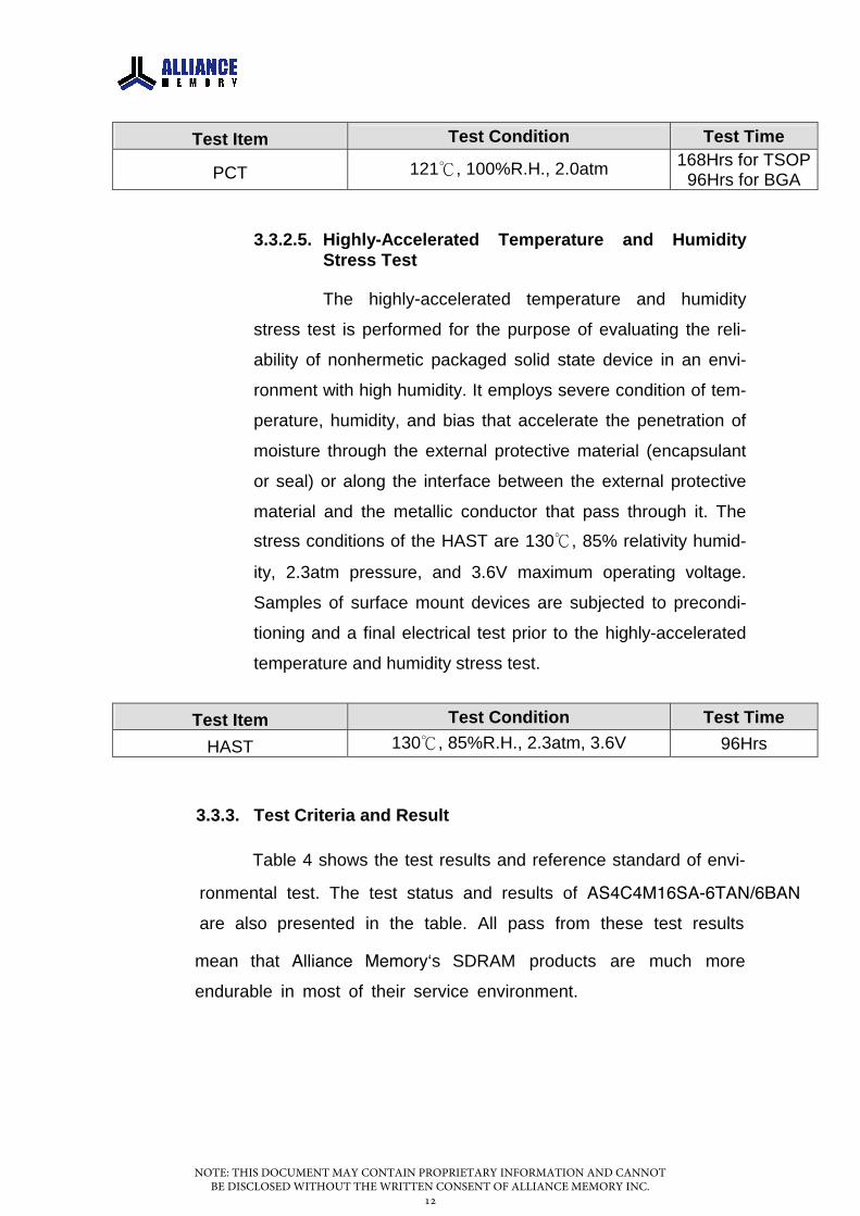
PCT 121, 100%R.H., 2.0atm 168Hrs for TSOP 96Hrs for BGA
3.3.2.5. Highly-Accelerated Temperature and Humidity Stress Test
The highly-accelerated temperature and humidity
stress test is performed for the purpose of evaluating the reli-
ability of nonhermetic packaged solid state device in an envi-
ronment with high humidity. It employs severe condition of tem-
perature, humidity, and bias that accelerate the penetration of
moisture through the external protective material (encapsulant
or seal) or along the interface between the external protective
material and the metallic conductor that pass through it. The
stress conditions of the HAST are 130, 85% relativity humid-
ity, 2.3atm pressure, and 3.6V maximum operating voltage.
Samples of surface mount devices are subjected to precondi-
tioning and a final electrical test prior to the highly-accelerated
temperature and humidity stress test.
Test Item Test Condition Test Time
HAST 130, 85%R.H., 2.3atm, 3.6V 96Hrs
3.3.3. Test Criteria and Result
Table 4 shows the test results and reference standard of envi-
ronmental test. The test status and results of AS4C4M16SA-6TAN/6BAN are also presented in the table. All pass from these test results
mean that Alliance Memory‘s SDRAM products are much more endurable in most of their service environment.
NOTE: THIS DOCUMENT MAY CONTAIN PROPRIETARY INFORMATION AND CANNOT BE DISCLOSED WITHOUT THE WRITTEN CONSENT OF ALLIANCE MEMORY INC.
12

Test Item Reference Standard
A/R Criteria Failure/S.S. Status Failure Mode
Moisture Sensitivity J-STD-020 0/1 0/231 x 3 PASS N/A
HTST JESD22-A103 0/1 0/45 x 1 PASS N/A
TCT* JESD22-A104 0/1 0/77 x 3 PASS N/A
PCT* JESD22-A102 0/1 0/77 x 3 PASS N/A
HAST* JESD22-A110 0/1 0/77 x 3 PASS N/A
* Sampling from Moisture Sensitivity
Table 4. Environmental Test Criteria and Result
3.4. ESD Test
Electrical discharge into semiconductor product is one of the leading
causes of device failure in the customer‘s manufacturing process. Alliance Memory performs the ESD test to ensure that the performance of AS4C4M16SA-6TAN/6BAN will not be degraded to an unacceptable level
by exposure to a succession of electrostatic discharge. The test methods
and test results are shown in Table 5.
Test Method Test Item
Reference Standard Test Condition Criteria Sample
Result (F/S.S)
H.B.M. AEC Q100-002 R=1.5KΩ, C=100pF ≥±2KV 3ea 0/3
M.M. AEC Q100-003 R=0KΩ, C=200pF ≥±200V 3ea 0/3
C.D.M. AEC Q100-011 Non-Socket Mode ≥±1KV 3ea 0/3
Table 5. ESD Test Condition and Result
3.5. Latch-Up Test
CMOS products can be prone to over-voltage exceeding the maximum
device rating if the parasitic p-n-p-n SCRs (Silicon-controlled rectifier) are im-
properly biased. When the SCR turns on, it draws excessive current and
causes products being damaged by thermal runaway. The Table 6 shows the
latch-up test method and the test result of no failure.
NOTE: THIS DOCUMENT MAY CONTAIN PROPRIETARY INFORMATION AND CANNOT BE DISCLOSED WITHOUT THE WRITTEN CONSENT OF ALLIANCE MEMORY INC.
13

Test Method Test Item
Reference Standard Test Condition & Criteria Sample
Result (F/S.S)
Latch-Up AEC Q100-004
Vtr(+)≧1.5 * Vcc Vtr(-)≦-0.5 * Vcc
Itr(+)≧100mA Itr(-)≦-100mA
6ea 0/6
Table 6. Latch-Up test Condition and Result
4. CONCLUSION
Reliability test is to ensure the ability of a product in order to perform a re-
quired function under specific conditions for a certain period of time. Through
those tests, the devices of potential failure can be screened out before shipping to
the customer. At the same time, the test results are fed back to process, design
and other related departments for improving product quality and reliability.
According to the life time test data, the short-term 48Hrs failure rate (=
the normal operation 0-1 year) of AS4C4M16SA-6TAN/6BAN is equal to 0
DPM at Ta=55°C and Vcc=3.3V with 60% confidence level AND the
long-term 1000Hrs failure rate (= the normal operation 1-10 year)
of AS4C4M16SA-6TAN/6BAN is equal to 22 FIT at Ta=55°C and Vcc=3.3V with
60% confidence level. The results of environmental test, ESD test and latch-up
test also ensure that the
AS4C4M16SA-6TAN/6BAN is manufactured under a precise control of quality
work by Alliance Memory and its subcontractors. Thus, this experiment based on the
Alliance Memory reliability test standard for above test items can all
pass.
With the extensive research and development activities and the
cooperation of all departments, Alliance Memory continuously sets and maintains higher standard of quality and reliability to satisfy the future demand of its
customers.
NOTE: THIS DOCUMENT MAY CONTAIN PROPRIETARY INFORMATION AND CANNOT BE DISCLOSED WITHOUT THE WRITTEN CONSENT OF ALLIANCE MEMORY INC.
14